JP7635692B2 - Vehicle suspension control device - Google Patents
Vehicle suspension control device Download PDFInfo
- Publication number
- JP7635692B2 JP7635692B2 JP2021163996A JP2021163996A JP7635692B2 JP 7635692 B2 JP7635692 B2 JP 7635692B2 JP 2021163996 A JP2021163996 A JP 2021163996A JP 2021163996 A JP2021163996 A JP 2021163996A JP 7635692 B2 JP7635692 B2 JP 7635692B2
- Authority
- JP
- Japan
- Prior art keywords
- control
- road surface
- vehicle
- preview
- gain
- Prior art date
- Legal status (The legal status is an assumption and is not a legal conclusion. Google has not performed a legal analysis and makes no representation as to the accuracy of the status listed.)
- Active
Links
Images


Landscapes
- Vehicle Body Suspensions (AREA)
Description
本開示は、サスペンションストロークを制御するアクチュエータを備える車両用サスペンション制御装置に関する。 This disclosure relates to a vehicle suspension control device that includes an actuator that controls the suspension stroke.
特許文献1は、自動運転コントローラから受け取った車輪の走行経路に関する情報に基づき、アクティブサスペンションの制御を行う技術を開示している。
車両のばね上構造体の振動を低減するプレビュー制御では、制御対象輪のサスペンションストロークを制御するアクチュエータを制御するために、路面の上下方向の変位に関連する路面変位関連値を位置と関連付けてマップ化した路面データマップを用いることが考えられる。現在時刻からプレビュー時間後の制御対象輪の予測通過位置における路面変位関連値を当該路面データマップから取得する際、車両の自己位置情報の取得誤差が大きいと、適切なプレビュー制御を行うことが困難となる場合がある。その結果、車両のユーザは、プレビュー制御の実行に起因する乗り心地の違和感を覚える可能性がある。 In preview control that reduces vibrations in the sprung structure of a vehicle, a road surface data map that maps road surface displacement-related values related to vertical displacement of the road surface and positions can be used to control the actuator that controls the suspension stroke of the controlled wheel. When obtaining road surface displacement-related values at the predicted passing position of the controlled wheel from the current time after the preview time from the road surface data map, if there is a large error in obtaining the vehicle's self-position information, it may be difficult to perform appropriate preview control. As a result, the user of the vehicle may feel an uncomfortable ride caused by the execution of the preview control.
本開示は、上述のような課題に鑑みてなされたものであり、車両の自己位置情報の取得誤差が大きい状況下におけるプレビュー制御の実行に起因する乗り心地の違和感を抑制できる車両用サスペンション制御装置を提供することを目的とする。 The present disclosure has been made in consideration of the above-mentioned problems, and aims to provide a vehicle suspension control device that can reduce discomfort in ride comfort caused by the execution of preview control in a situation where there is a large error in obtaining the vehicle's own position information.
本開示の第1の態様に係る車両用サスペンション制御装置は、アクチュエータと、電子制御ユニットと、を備える。アクチュエータは、制御対象輪のサスペンションストロークを制御する。電子制御ユニットは、アクチュエータを制御することにより、車両のばね上構造体の振動を低減するプレビュー制御を実行する。電子制御ユニットは、車両の自己位置情報を取得する位置取得処理と、路面の上下方向の変位に関連する路面変位関連値を位置と関連付けてマップ化した路面データマップから、現在時刻からプレビュー時間後の制御対象輪の予測通過位置における路面変位関連値を取得する路面情報取得処理と、自己位置情報の信頼度を算出する信頼度算出処理と、予測通過位置における路面変位関連値に基づいてプレビュー制御を実行する制御処理と、を実行する。制御処理において、電子制御ユニットは、信頼度が第1閾値以下の場合には、信頼度が第1閾値より高い場合と比べて抑制された態様でプレビュー制御を実行する。 A vehicle suspension control device according to a first aspect of the present disclosure includes an actuator and an electronic control unit. The actuator controls the suspension stroke of a controlled wheel. The electronic control unit controls the actuator to execute preview control for reducing vibration of a sprung structure of the vehicle. The electronic control unit executes a position acquisition process for acquiring self-position information of the vehicle, a road surface information acquisition process for acquiring a road surface displacement-related value at a predicted passing position of the controlled wheel from a road surface data map in which a road surface displacement-related value related to the vertical displacement of the road surface is associated with a position and mapped, a reliability calculation process for calculating a reliability of the self-position information, and a control process for executing preview control based on the road surface displacement-related value at the predicted passing position. In the control process, when the reliability is equal to or less than a first threshold, the electronic control unit executes the preview control in a more suppressed manner than when the reliability is higher than the first threshold.
本開示の第2の態様に係る車両用サスペンション制御装置は、アクチュエータと、電子制御ユニットと、を備える。アクチュエータは、制御対象輪のサスペンションストロークを制御する。電子制御ユニットは、アクチュエータを制御することにより、車両のばね上構造体の振動を低減するプレビュー制御を実行する。電子制御ユニットは、車両の車速を取得する処理と、車両の自己位置情報を取得する位置取得処理と、路面の上下方向の変位に関連する路面変位関連値を位置と関連付けてマップ化した路面データマップから、現在時刻からプレビュー時間後の制御対象輪の予測通過位置における路面変位関連値を取得する路面情報取得処理と、予測通過位置における路面変位関連値に基づいてプレビュー制御を実行する制御処理と、を実行する。制御処理において、電子制御ユニットは、車速が第2閾値以下の場合には、車速が第2閾値より高い場合と比べて抑制された態様でプレビュー制御を実行する。 A vehicle suspension control device according to a second aspect of the present disclosure includes an actuator and an electronic control unit. The actuator controls the suspension stroke of a controlled wheel. The electronic control unit controls the actuator to execute preview control for reducing vibration of a sprung structure of the vehicle. The electronic control unit executes a process for acquiring the vehicle speed, a position acquisition process for acquiring the vehicle's own position information, a road surface information acquisition process for acquiring a road surface displacement-related value at a predicted passing position of the controlled wheel from the current time after the preview time from a road surface data map in which a road surface displacement-related value related to the vertical displacement of the road surface is associated with a position and mapped, and a control process for executing preview control based on the road surface displacement-related value at the predicted passing position. In the control process, when the vehicle speed is equal to or less than a second threshold, the electronic control unit executes the preview control in a more suppressed manner than when the vehicle speed is higher than the second threshold.
本開示の第3の態様に係る車両用サスペンション制御装置は、アクチュエータと、電子制御ユニットと、を備える。アクチュエータは、制御対象輪のサスペンションストロークを制御する。電子制御ユニットは、アクチュエータを制御することにより、車両のばね上構造体の振動を低減するプレビュー制御を実行する。電子制御ユニットは、車両の車速を取得する処理と、車両の自己位置情報を取得する位置取得処理と、路面の上下方向の変位に関連する路面変位関連値を位置と関連付けてマップ化した路面データマップから、現在時刻からプレビュー時間後の制御対象輪の予測通過位置における路面変位関連値を取得する路面情報取得処理と、自己位置情報の信頼度を算出する信頼度算出処理と、予測通過位置における路面変位関連値に基づいてプレビュー制御を実行する制御処理と、を実行する。制御処理において、電子制御ユニットは、信頼度が第1閾値以下であること、及び、車速が第2閾値以下であることのうちの少なくとも一方の条件が満たされる場合には、信頼度が第1閾値より高く且つ車速が第2閾値より高い場合と比べて抑制された態様でプレビュー制御を実行する。 A vehicle suspension control device according to a third aspect of the present disclosure includes an actuator and an electronic control unit. The actuator controls the suspension stroke of the controlled wheel. The electronic control unit controls the actuator to execute preview control to reduce vibration of the sprung structure of the vehicle. The electronic control unit executes a process of acquiring the vehicle speed, a process of acquiring the vehicle's own position information, a process of acquiring road surface displacement-related values at a predicted passing position of the controlled wheel from the current time after the preview time from a road surface data map in which road surface displacement-related values related to vertical displacement of the road surface are associated with positions and mapped, a process of calculating the reliability of the own position information, and a control process of executing preview control based on the road surface displacement-related values at the predicted passing position. In the control process, when at least one of the conditions that the reliability is equal to or less than a first threshold and the vehicle speed is equal to or less than a second threshold is satisfied, the electronic control unit executes the preview control in a more suppressed manner than when the reliability is higher than the first threshold and the vehicle speed is higher than the second threshold.
本開示の第1の態様によれば、自己位置情報の信頼度が低い場合にはプレビュー制御が抑制される。また、車速が低い場合には、自己位置情報の取得誤差が大きくなり易い。このため、第2の態様によれば、車速が低い場合にはプレビュー制御が抑制される。そして、第3の態様によれば、自己位置情報の信頼度が低く且つ車速が低い場合にはプレビュー制御が抑制される。第1~第3の態様のそれぞれによれば、自己位置情報の取得誤差が大きい状況下におけるプレビュー制御の実行に起因する乗り心地の違和感を抑制できる。 According to a first aspect of the present disclosure, preview control is suppressed when the reliability of the self-location information is low. Furthermore, when the vehicle speed is low, the acquisition error of the self-location information is likely to be large. For this reason, according to a second aspect, preview control is suppressed when the vehicle speed is low. And, according to a third aspect, preview control is suppressed when the reliability of the self-location information is low and the vehicle speed is low. According to each of the first to third aspects, it is possible to suppress the discomfort of the ride caused by the execution of preview control in a situation where the acquisition error of the self-location information is large.
以下に示す実施の形態において各要素の個数、数量、量、範囲等の数に言及した場合、特に明示した場合や原理的に明らかにその数に特定される場合を除いて、その言及した数に、本開示に係る技術思想が限定されるものではない。 When the number, quantity, amount, range, etc. of each element is mentioned in the embodiments described below, the technical ideas of this disclosure are not limited to the mentioned numbers, unless otherwise specified or clearly specified in principle.
1.実施の形態1
1-1.サスペンション及び路面変位関連値
図1は、実施の形態1に係る車両1の構成例を示す概略図である。車両1は、車輪2とサスペンション3を備えている。車輪2は、左前輪2FL、右前輪2FR、左後輪2RL、及び右後輪2RRを含んでいる。それら左前輪2FL、右前輪2FR、左後輪2RL、及び右後輪2RRのそれぞれに対してサスペンション3FL、3FR、3RL、及び3RRが設けられている。以下の説明では、特に区別の必要が無い場合、各車輪を車輪2と呼び、各サスペンションをサスペンション3と呼ぶ。
1. First embodiment
1-1. Suspension and road surface displacement related values Fig. 1 is a schematic diagram showing a configuration example of a
図2は、実施の形態1に係るサスペンション3の構成例を示す概念図である。サスペンション3は、車両1のばね下構造体4とばね上構造体5との間を連結するように設けられている。ばね下構造体4は、車輪2を含んでいる。サスペンション3は、スプリング3S、ダンパ(ショックアブソーバ)3D、及びアクチュエータ3Aを含んでいる。スプリング3S、ダンパ3D、及びアクチュエータ3Aは、ばね下構造体4とばね上構造体5との間に並列に設けられている。アクチュエータ3Aはサスペンション3のストロークSTを制御する。スプリング3Sのばね定数はKである。ダンパ3Dの減衰係数はCである。アクチュエータ3Aは、ばね下構造体4とばね上構造体5との間に上下方向の制御力Fcを作用させる。
Figure 2 is a conceptual diagram showing an example of the configuration of the
より詳細には、アクチュエータ3Aは、例えば、電動式又は油圧式のアクティブアクチュエータ(いわゆる、フルアクティブサスペンションを構成するアクチュエータ)である。あるいは、アクチュエータ3Aは、例えば、ダンパ3Dが発生させる減衰力を可変とするアクチュエータ、又は、アクティブスタビライザ装置のアクチュエータであってもよい。更に、本開示に係る「アクチュエータ」は、例えば、サスペンションジオメトリの利用により、車輪に作用する車両前後力(駆動力及び制動力)を制御力Fcに変換可能に構成されたサスペンションを備える車両において当該車両前後力を発生させるアクチュエータ(例えば、電動機)であってもよい。当該電動機は、例えば、車輪に備えらえたインホイールモータ(IWM)であってもよいし、あるいは、車両駆動軸を介して車輪を駆動可能な電動機であってもよい。
More specifically, the
ここで、用語の定義を行う。「路面変位Zr」は、路面RSの上下方向の変位である。「ばね下変位Zu」は、ばね下構造体4の上下方向の変位である。「ばね上変位Zs」は、ばね上構造体5の上下方向の変位である。「ばね下速度Zu'」は、ばね下構造体4の上下方向の速度である。「ばね上速度Zs'」は、ばね上構造体5の上下方向の速度である。「ばね下加速度Zu''」は、ばね下構造体4の上下方向の加速度である。「ばね上加速度Zs''」は、ばね上構造体5の上下方向の加速度である。なお、各パラメータの符号は、上向きの場合に正であり、下向きの場合に負である。
Here, the terms are defined. "Road surface displacement Zr" is the vertical displacement of the road surface RS. "Unsprung displacement Zu" is the vertical displacement of the unsprung structure 4. "Sprung displacement Zs" is the vertical displacement of the
車輪2は、路面RS上を移動する。以下の説明において、路面変位Zrに関連する値を、「路面変位関連値」と呼ぶ。路面変位関連値としては、上記の路面変位Zr、路面変位Zrの時間微分値である路面変位速度Zr’、ばね下変位Zu、ばね下速度Zu'、ばね下加速度Zu''、ばね上変位Zs、ばね上速度Zs'、ばね上加速度Zs''、等が例示される。路面変位関連値は、車輪2の上下運動(vertical motion)に関連するパラメータである「上下運動パラメータ」であると言うこともできる。 The wheel 2 moves on the road surface RS. In the following description, values related to the road surface displacement Zr are referred to as "road surface displacement related values". Examples of road surface displacement related values include the above road surface displacement Zr, the road surface displacement velocity Zr' which is the time derivative value of the road surface displacement Zr, the unsprung displacement Zu, the unsprung velocity Zu', the unsprung acceleration Zu'', the sprung displacement Zs, the sprung velocity Zs', the sprung acceleration Zs'', etc. The road surface displacement related values can also be said to be "vertical motion parameters", which are parameters related to the vertical motion of the wheel 2.
一例として、以下の説明においては、路面変位関連値がばね下変位Zuである場合について考える。一般化する場合は、以下の説明における「ばね下変位」を「路面変位関連値」で読み替えるものとする。 As an example, in the following explanation, we consider a case where the road surface displacement-related value is the unsprung displacement Zu. When generalizing, the "unsprung displacement" in the following explanation should be read as the "road surface displacement-related value."
図3は、ばね下変位算出処理の一例を示すフローチャートである。 Figure 3 is a flowchart showing an example of the unsprung displacement calculation process.
ステップS11において、ばね上構造体5に設置されたばね上加速度センサ22によってばね上加速度Zs''が検出される。ステップS12において、ばね上加速度Zs''を2階積分することによりばね上変位Zsが算出される。
In step S11, the sprung acceleration Zs'' is detected by the sprung
ステップS13において、ばね上構造体5とばね下構造体4との間の相対変位であるストロークST(=Zs-Zu)が取得される。例えば、ストロークSTは、サスペンション3に設置されたストロークセンサにより検出される。他の例として、ストロークSTは、単輪2自由度モデルに基づいて構成されたオブザーバによって、ばね上加速度Zs''に基づいて推定されてもよい。
In step S13, the stroke ST (= Zs - Zu), which is the relative displacement between the sprung
ステップS14において、センサドリフト等の影響を抑えるために、ばね上変位Zsの時系列データに対してフィルタリング処理が行われる。同様に、ステップS15において、ストロークSTの時系列データに対してフィルタリング処理が行われる。例えば、フィルタは、特定周波数帯の信号成分を通過させるバンドパスフィルタである。特定周波数帯は、車両1のばね上共振周波数を含むように設定されてもよい。例えば、特定周波数帯は、0.3~10Hzである。付け加えると、これらのフィルタリング処理は、後述の「制御処理」に含まれる「フィルタリング処理」とは別に実行されるものである。
In step S14, in order to suppress the effects of sensor drift, etc., a filtering process is performed on the time series data of the sprung displacement Zs. Similarly, in step S15, a filtering process is performed on the time series data of the stroke ST. For example, the filter is a band-pass filter that passes signal components in a specific frequency band. The specific frequency band may be set to include the sprung resonance frequency of the
ステップS16において、ばね上変位ZsとストロークSTとの差分がばね下変位Zuとして算出される。 In step S16, the difference between the sprung displacement Zs and the stroke ST is calculated as the unsprung displacement Zu.
ステップS14及びS15の代わりに、ステップS16において算出されるばね下変位Zuの時系列データに対してフィルタリング処理が行われてもよい。 Instead of steps S14 and S15, a filtering process may be performed on the time series data of the unsprung displacement Zu calculated in step S16.
更に他の例として、ばね下加速度センサによってばね下加速度Zu''が検出され、ばね下加速度Zu''からばね下変位Zuが算出されてもよい。 As yet another example, the unsprung acceleration Zu'' may be detected by an unsprung acceleration sensor, and the unsprung displacement Zu may be calculated from the unsprung acceleration Zu''.
1-2.車両制御システム
1-2-1.構成例
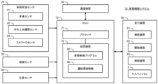
図4は、実施の形態1に係る車両制御システム10の構成例を示すブロック図である。車両制御システム10は、車両1に搭載され、車両1を制御する。車両制御システム10は、車両状態センサ20、認識センサ30、位置センサ40、通信装置50、走行装置60、及び電子制御ユニット(ECU)70を含んでいる。
4 is a block diagram showing a configuration example of the
車両状態センサ20は、車両1の状態を検出する。車両状態センサ20は、車両1の車速Vを検出する車速センサ(車輪速センサ)21、ばね上加速度Zs''を検出するばね上加速度センサ22、等を含んでいる。車両状態センサ20は、ストロークSTを検出するストロークセンサ23を含んでいてもよい。車両状態センサ20は、ばね下加速度センサを含んでいてもよい。その他、車両状態センサ20は、横加速度センサ、ヨーレートセンサ、舵角センサ、等を含んでいる。
The
認識センサ30は、車両1の周囲の状況を認識(検出)する。認識センサとしては、カメラ、LIDAR(Laser Imaging Detection and Ranging)、レーダ、等が例示される。
The
位置センサ40は、車両1の位置及び方位を検出する。例えば、位置センサ40は、GNSS(Global Navigation Satellite System)受信機を含んでいる。
The
通信装置50は、車両1の外部と通信を行う。
The
走行装置60は、操舵装置61、駆動装置62、制動装置63、及びサスペンション3(図2参照)を含んでいる。操舵装置61は、車輪2を転舵する。例えば、操舵装置61は、パワーステアリング(EPS: Electric Power Steering)装置を含んでいる。駆動装置62は、駆動力を発生させる動力源である。駆動装置62としては、エンジン、電動機、インホイールモータ、等が例示される。制動装置63は、制動力を発生させる。
The traveling
ECU70は、車両1を制御するコンピュータである。ECU70は、1又は複数のプロセッサ71(以下、単にプロセッサ71と呼ぶ)と1又は複数の記憶装置72(以下、単に記憶装置72と呼ぶ)を含んでいる。プロセッサ71は、各種処理を実行する。例えば、プロセッサ71は、CPU(Central Processing Unit)を含んでいる。記憶装置72は、プロセッサ71による処理に必要な各種情報を格納する。記憶装置72としては、揮発性メモリ、不揮発性メモリ、HDD(Hard Disk Drive)、SSD(Solid State Drive)、等が例示される。ECU70は複数であってもよい。
The
車両制御プログラム80は、車両1を制御するためのコンピュータプログラムであり、プロセッサ71によって実行される。車両制御プログラム80は、記憶装置72に格納される。あるいは、車両制御プログラム80は、コンピュータ読み取り可能な記録媒体に記録されてもよい。プロセッサ71が車両制御プログラム80を実行することにより、ECU70の機能が実現される。なお、ECU70は、本開示に係る「車両用サスペンション制御装置」が備える「電子制御ユニット」の一例に相当する。
The
1-2-2.運転環境情報
図5は、車両1の運転環境を示す運転環境情報90の一例を示すブロック図である。運転環境情報90は、記憶装置72に格納される。運転環境情報90は、地図情報91、車両状態情報92、周辺状況情報93、及び位置情報94を含んでいる。
5 is a block diagram showing an example of driving
地図情報91は、一般的なナビゲーション地図を含む。地図情報91は、レーン配置、道路形状、等を示していてもよい。地図情報91は、白線、信号機、標識、ランドマーク、等の位置情報を含んでいてもよい。地図情報91は、地図データベースから得られる。なお、地図データベースは、車両1に搭載されていてもよいし、外部の管理サーバに格納されていてもよい。後者の場合、ECU70は、管理サーバと通信を行い、必要な地図情報91を取得する。
The
地図情報91は、更に、「ばね下変位マップ200」を含んでいる。ばね下変位マップ200の詳細については後述される。
The
車両状態情報92は、車両1の状態を示す情報である。ECU70は、車両状態センサ20から車両状態情報92を取得する。例えば、車両状態情報92は、車速V、ばね上加速度Zs''、ストロークST、横加速度、ヨーレート、舵角、等を含む。車速Vは、位置センサ40によって検出される車両位置から算出されてもよい。ECU70は、図3で示された手法によりばね下変位Zuを算出してもよい。その場合、車両状態情報92は、ECU70によって算出されたばね下変位Zuも含む。
The
周辺状況情報93は、車両1の周囲の状況を示す情報である。ECU70は、認識センサ30を用いて車両1の周囲の状況を認識し、周辺状況情報93を取得する。例えば、周辺状況情報93は、カメラによって撮像される画像情報を含む。他の例として、周辺状況情報93は、LIDARによって得られる点群情報を含む。
The surrounding
周辺状況情報93は、更に、車両1の周囲の物体に関する「物体情報」を含んでいる。物体としては、歩行者、自転車、他車両(先行車両、駐車車両、等)、道路構成(白線、縁石、ガードレール、壁、中央分離帯、路側構造物、等)、標識、ポール、障害物、等が例示される。
The surrounding
位置情報94は、車両1の位置及び方位(車両進行方向)を示す情報である。ECU70は、GNSS受信機等の位置センサ40による測定結果から位置情報94を取得する。
The
1-2-3.車両制御
ECU70は、車両1の走行を制御する車両走行制御を実行する。車両走行制御は、操舵制御、駆動制御、及び制動制御を含む。ECU70は、走行装置60(操舵装置61、駆動装置62、及び制動装置63)を制御することによって車両走行制御を実行する。ECU70は、運転環境情報90に基づいて、車両1の運転を支援する運転支援制御を行ってもよい。運転支援制御としては、車線維持制御、衝突回避制御、自動運転制御、等が例示される。
1-2-3. Vehicle
更に、ECU70は、サスペンション3を制御する。具体的には、ECU70は、サスペンション3を制御して車両1の振動を抑制する制振制御を行う。ECU70は、アクチュエータ3Aを制御して、ばね下構造体4とばね上構造体5との間に上下方向の制御力Fcを発生させる(図2参照)。制振制御は、後述される「プレビュー制御」を含んでいる。
Furthermore, the
1-3.マップ管理システム
1-3-1.構成例
図6は、実施の形態1に係るマップ管理システム100の構成例を示すブロック図である。マップ管理システム100は、各種の地図情報を管理するコンピュータである。地図情報の管理は、地図情報の生成、更新、提供、配信、等を含む。典型的には、マップ管理システム100は、クラウド上の管理サーバである。マップ管理システム100は、複数のサーバが分散処理を行う分散システムであってもよい。
1-3. Map management system 1-3-1. Configuration example Fig. 6 is a block diagram showing a configuration example of the
マップ管理システム100は、通信装置110を含んでいる。通信装置110は、通信ネットワークNETに接続されている。例えば、通信装置110は、通信ネットワークNETを介して多数の車両1と通信を行う。
The
マップ管理システム100は、更に、1又は複数のプロセッサ120(以下、単にプロセッサ120と呼ぶ)及び1又は複数の記憶装置130(以下、単に記憶装置130と呼ぶ)を含んでいる。プロセッサ120は、各種情報処理を実行する。例えば、プロセッサ120は、CPUを含んでいる。記憶装置130は、各種の地図情報を格納する。また、記憶装置130は、プロセッサ120による処理に必要な各種情報を格納する。記憶装置130としては、揮発性メモリ、不揮発性メモリ、HDD、SSD、等が例示される。
The
マップ管理プログラム140は、マップ管理のためのコンピュータプログラムであり、プロセッサ120によって実行される。マップ管理プログラム140は、記憶装置130に格納される。あるいは、マップ管理プログラム140は、コンピュータ読み取り可能な記録媒体に記録されてもよい。プロセッサ120がマップ管理プログラム140を実行することにより、マップ管理システム100の機能が実現される。
The
プロセッサ120は、通信装置110を介して車両1の車両制御システム10と通信を行う。プロセッサ120は、車両制御システム10から各種情報を収集し、収集した情報に基づいて地図情報を生成、更新する。また、プロセッサ120は、車両制御システム10に地図情報を配信する。また、プロセッサ120は、車両制御システム10からのリクエストに応答して地図情報を提供する。
The
1-3-2.ばね下変位マップ(路面データマップ)
マップ管理システム100が管理する地図情報の一つが、「ばね下変位マップ200」である。ばね下変位マップ200は、ばね下変位Zu(路面変位関連値)に関する地図である。ばね下変位マップ200は、記憶装置130に格納されている。なお、ばね下変位マップ200は、本開示に係る「路面の上下方向の変位に関連する路面変位関連値を位置と関連付けてマップ化した路面データマップ」の一例に相当する。
1-3-2. Unsprung displacement map (road surface data map)
One of the map information managed by the
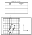
図7は、ばね下変位マップ200を説明するための概念図である。XY面は水平面を表す。例えば、水平面における絶対座標系は緯度方向と経度方向により定義され、位置は緯度と経度により定義される。ばね下変位マップ200は、少なくとも位置(X,Y)とばね下変位Zuとの対応関係を表す。言い換えれば、ばね下変位マップ200は、ばね下変位Zuを少なくとも位置(X,Y)の関数として表す。
Figure 7 is a conceptual diagram for explaining the
道路領域は、水平面上でメッシュ状に区分されてもよい。つまり、道路領域は、水平面上で複数の単位エリア(以下、「路面区画M」と称する)に区分されてもよい。路面区画Mは、例えば正方形である。正方形の1辺の長さは、例えば10cmである。ばね下変位マップ200は、路面区画Mの位置とばね下変位Zuとの対応関係を表す。路面区画Mの位置は、その路面区画Mの代表位置(例:中心位置)で定義されてもよいし、その路面区画Mの範囲(緯度範囲、経度範囲)で定義されてもよい。路面区画Mのばね下変位Zuは、例えば、その路面区画M内で取得されたばね下変位Zuの平均値である。路面区画Mを小さくするほど、ばね下変位マップ200の解像度は増加する。
The road area may be divided into a mesh shape on a horizontal plane. That is, the road area may be divided into a plurality of unit areas (hereinafter referred to as "road surface sections M") on a horizontal plane. The road surface section M is, for example, a square. The length of one side of the square is, for example, 10 cm. The
1-3-3.マップ生成/更新処理
プロセッサ120は、通信装置110を介して、多数の車両1から情報を収集する。そして、プロセッサ120は、多数の車両1から収集した情報に基づいて、ばね下変位マップ200の生成及び更新を行う。以下、マップ生成/更新処理の例について更に詳しく説明する。
1-3-3. Map Generation/Update Processing The
ばね下変位マップ200における位置は、車輪2が通過した位置である。各車輪2の位置は、上記の位置情報94に基づいて算出される。具体的には、車両1における車両位置の基準点と各車輪2との間の相対位置関係は既知情報である。その相対位置関係と位置情報94で示される車両位置に基づいて、各車輪2の位置を算出することができる。
The positions in the
ばね下変位Zuは、図3で示されたような手法により算出される。すなわち、車両1に搭載された車両状態センサ20を用いることによって、ばね上変位Zs及びストロークSTが得られる。これらばね上変位Zs及びストロークSTを、便宜上、「センサベース情報」と呼ぶ。ばね下変位Zuは、このセンサベース情報に基づいて算出される。
The unsprung displacement Zu is calculated using the method shown in FIG. 3. That is, the sprung displacement Zs and stroke ST are obtained by using the
例えば、車両1の走行中、車両制御システム10のECU70は、センサベース情報に基づいてリアルタイムにばね下変位Zuを算出する。また、ECU70は、同じタイミングの車輪位置とばね下変位Zuとを関連付ける。そして、ECU70は、車輪位置の時系列データとばね下変位Zuの時系列データのセットをマップ管理システム100に送信する。マップ管理システム100のプロセッサ120は、車輪位置の時系列データとばね下変位Zuの時系列データに基づいて、ばね下変位マップ200を生成、更新する。
For example, while the
他の例として、車両制御システム10のECU70は、同じタイミングの車輪位置とセンサベース情報とを関連付ける。そして、ECU70は、車輪位置の時系列データとセンサベース情報の時系列データのセットをマップ管理システム100に送信する。マップ管理システム100のプロセッサ120は、受信したセンサベース情報に基づいてばね下変位Zuを算出する。更に、プロセッサ120は、車輪位置の時系列データとばね下変位Zuの時系列データに基づいて、ばね下変位マップ200を生成、更新する。
As another example, the
なお、マップ管理システム100においてばね下変位Zuを算出する場合、処理時間の制約はないため、ゼロ位相フィルタを用いてフィルタリング処理を行うことができる。ゼロ位相フィルタを利用することにより、「位相ずれ」を防止することができる。
When calculating the unsprung displacement Zu in the
図8は、実施の形態1に係るマップ生成/更新処理を要約的に示すフローチャートである。
Figure 8 is a flowchart summarizing the map generation/update process for
ステップS21において、マップ管理システム100のプロセッサ120は、通信装置110を介して、車両1(車両制御システム10)から「マップ更新用情報」を取得する。マップ更新用情報は、車両1の位置(車輪位置)の時系列データを含む。また、マップ更新用情報は、ばね下変位Zuを算出するために必要なセンサベース情報(例えば、ばね上変位Zs及びストロークST)の時系列データを含む。あるいは、マップ更新用情報は、車両制御システム10のECU70によって算出されたばね下変位Zuの時系列データを含んでいてもよい。
In step S21, the
ステップS22において、マップ管理システム100のプロセッサ120は、マップ更新用情報に基づいて、ばね下変位マップ200を生成/更新する。
In step S22, the
1-3-4.変形例
車両1の車両制御システム10が、ばね下変位マップ200のデータベースを保持し、自身のばね下変位マップ200の生成/更新を行ってもよい。つまり、マップ管理システム100は車両制御システム10に含まれていてもよい。
The
1-4.ばね下変位マップを利用したプレビュー制御
車両制御システム10のECU70は、通信装置50を介してマップ管理システム100と通信を行う。ECU70は、車両1の現在位置を含むエリアのばね下変位マップ200をマップ管理システム100から取得する。ばね下変位マップ200は、記憶装置72に格納される。そして、ECU70は、ばね下変位マップ200に基づいて、制振制御の一種である「プレビュー制御」を実行する。
1-4. Preview control using unsprung displacement map The
1-4-1.プレビュー制御の基本構成
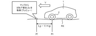
図9は、プレビュー制御を説明するための概念図である。図10は、プレビュー制御に関する処理の基本的な流れを示すフローチャートである。図9及び図10を参照して、プレビュー制御について説明する。プレビュー制御は、ばね上構造体5の振動を低減するために実行される。
1-4-1. Basic configuration of preview control Fig. 9 is a conceptual diagram for explaining the preview control. Fig. 10 is a flowchart showing a basic flow of processing related to the preview control. The preview control will be explained with reference to Figs. 9 and 10. The preview control is executed to reduce vibration of the sprung
ステップS31において、ECU70は、各車輪2の現在位置P0を取得する。車両1における車両位置の基準点と各車輪2との間の相対位置関係は既知情報である。その相対位置関係と位置情報94で示される車両位置に基づいて、各車輪2の位置を算出することができる。
In step S31, the
ステップS32において、ECU70は、プレビュー時間tp後の車輪2の予測通過位置Pfを算出する。プレビュー時間tpは、例えば、ECU70が予測通過位置Pfを特定してからサスペンション3のアクチュエータ3Aが目標制御力Fc_tに対応する制御力Fcを出力するまでに要する時間となるように予め設定されている。プレビュー距離Lpは、プレビュー時間tpと車速Vの積により与えられる。予測通過位置Pfは、車輪2が移動すると予測される移動予測進路に沿って現在位置P0からプレビュー距離Lpだけ車両進行方向の前方の位置である。移動予測進路は、例えば、車両1の進行方向Tdと車輪2の現在位置P0とに基づいて特定できる。進行方向Tdは、例えば次の手法で特定できる。すなわち、ECU70は、前回の時間ステップの現在位置P0及び現在の時間ステップの現在位置P0を地図情報91にマッピングしたうえで、前回の時間ステップの現在位置から現在の時間ステップの現在位置P0に向かう方向を進行方向Tdとして特定する。変形例として、ECU70は、車速Vと車輪2の舵角に基づいて予想走行ルートを算出し、予想走行ルートに基づいて予測通過位置Pfを算出してもよい。
In step S32, the
ステップS33において、ECU70は、予測通過位置Pfにおけるばね下変位Zuをばね下変位マップ200から読み出す。
In step S33, the
ステップS34において、ECU70は、予測通過位置Pfにおけるばね下変位Zuに基づいて、サスペンション3のアクチュエータ3Aの目標制御力Fc_tを算出する。目標制御力Fc_tは、例えば、次のように算出される。この目標制御力Fc_tは、プレビュー制御のために必要とされる制御力Fcの要求値(すなわち、要求制御量Xpv)に相当する。
In step S34, the
ばね上構造体5(図2参照)に関する運動方程式は、次の式(1)により表される。
m・Zs''=C(Zu'-Zs')+K(Zu-Zs)-Fc ・・・(1)
The equation of motion for the sprung structure 5 (see FIG. 2) is expressed by the following equation (1).
m・Zs''=C(Zu'-Zs')+K(Zu-Zs)-Fc...(1)
式(1)において、mはばね上構造体5の質量であり、Cはダンパ3Dの減衰係数であり、Kはスプリング3Sのばね定数であり、Fcはアクチュエータ3Aが発生させる上下方向の制御力である。仮に、制御力Fcによってばね上構造体5の振動が完全に打ち消される場合(Zs''=0,Zs'=0,Zs=0)、その制御力Fcは次の式(2)により表される。
Fc=C・Zu'+K・Zu ・・・(2)
In equation (1), m is the mass of the sprung
Fc=C・Zu'+K・Zu...(2)
少なくとも制振効果をもたらす制御力Fcは、次の式(3)により表される。
Fc=α・C・Zu'+β・K・Zu ・・・(3)
The control force Fc that provides at least the vibration damping effect is expressed by the following equation (3).
Fc=α・C・Zu'+β・K・Zu...(3)
式(3)において、制御ゲインαは、0より大きく且つ1以下であり、制御ゲインβも、0より大きく且つ1以下である。式(3)中の微分項を省略した場合、少なくとも制振効果をもたらす制御力Fcは、次の式(4)により表される。
Fc=β・K・Zu ・・・(4)
In formula (3), the control gain α is greater than 0 and less than or equal to 1, and the control gain β is also greater than 0 and less than or equal to 1. When the differential term in formula (3) is omitted, a control force Fc that provides at least a vibration damping effect is expressed by the following formula (4).
Fc=β・K・Zu...(4)
ECU70は、上記式(3)あるいは式(4)に従って、目標制御力Fc_tを算出する。すなわち、ECU70は、予測通過位置Pfにおけるばね下変位Zuを式(3)あるいは式(4)に代入して、目標制御力Fc_tを算出する。
The
ステップS35において、ECU70は、アクチュエータ3Aが目標制御力Fc_tに対応する制御力Fcを発生させるように、目標制御力Fc_tを含む制御指令をアクチュエータ3Aに送信する。アクチュエータ3Aは、現在時刻からプレビュー時間tpだけ後のタイミング(すなわち、車輪2が予測通過位置Pfを通過するタイミング)で目標制御力Fc_tに対応する制御力Fcを発生させる。
In step S35, the
以上に説明されたばね下変位マップ200を利用したプレビュー制御によれば、車輪2の予測通過位置Pfのばね下変位Zu(路面変位関連値)に起因して生じるばね上構造体5の振動を抑制する制御力Fcを適切なタイミングで発生できる。これにより、ばね上構造体5(車体)の振動を効果的に抑制することが可能となる。
According to the preview control using the
1-4-2.位置信頼度を考慮したプレビュー制御
プレビュー制御において、予測通過位置Pfのばね下変位Zuをばね下変位マップ200から取得する際、GNSS受信機等の位置センサ40を利用して取得される車両1の自己位置情報の誤差(以下、単に「位置誤差」とも称する)が大きいと、ばね下変位Zu(路面変位関連値)の推定精度が低下する可能性がある。より詳細には、位置誤差が大きいと、本来の車輪2の位置(すなわち、本来読み込むべき位置)と異なる位置のばね下変位Zuが取得されてしまう。つまり、取得されたばね下変位Zuは、本来の車輪2の位置での値から乖離したものとなる。その結果、適切なプレビュー制御を行うことが困難となる場合がある。具体的には、例えば、プレビュー制御の実行に起因してばね上構造体5の振動が増加する可能性がある。その結果、車両のユーザは、プレビュー制御の実行に起因する乗り心地の違和感を覚える可能性がある。
1-4-2. Preview control considering position reliability In the preview control, when the unsprung displacement Zu of the predicted passing position Pf is acquired from the
上記の課題に鑑み、実施の形態1においてプレビュー制御のためにECU70によって実行される処理は、「位置取得処理」及び「路面情報取得処理」とともに、「信頼度算出処理」、及び「制御処理」を含んでいる。これらの処理の一例は、図10に示すフローチャートの処理及び次の図11に示すフローチャートの処理を用いて説明される。
In consideration of the above-mentioned problems, in the first embodiment, the processes executed by the
位置取得処理は、車両1の自己位置情報を取得する処理であり、その一例は既に説明されたステップS31(図10参照)の処理である。また、路面情報取得処理は、ばね下変位マップ200から予測通過位置Pfのばね変位Zuを取得する処理であり、その一例は既に説明されたステップS33(図10参照)の処理である。
The position acquisition process is a process for acquiring the
信頼度算出処理は、自己位置情報の信頼度(以下、「位置信頼度」とも称する)Daを算出する処理であり、その一例は下記のステップS41(図11参照)の処理である。 The reliability calculation process is a process for calculating the reliability of the self-location information (hereinafter also referred to as "location reliability") Da, and an example of this is the process of step S41 below (see FIG. 11).
制御処理は、予測通過位置Pfにおけるばね下変位Zu(路面変位関連値)に基づいてプレビュー制御を実行する処理であり、その一例は、既に説明されたステップS34及びS35(図10参照)と下記のステップS42、S43、及びS44(図11参照)との組み合わせである。 The control process is a process that executes preview control based on the unsprung displacement Zu (road surface displacement related value) at the predicted passing position Pf, and an example of this is a combination of the already described steps S34 and S35 (see FIG. 10) and the following steps S42, S43, and S44 (see FIG. 11).
制御処理において、ECU70は、位置信頼度Daが所定の閾値Dath(第1閾値)以下の場合には、位置信頼度Daが閾値Dathより高い場合と比べて抑制された態様でプレビュー制御を実行する。
In the control process, when the position reliability Da is equal to or less than a predetermined threshold Dath (first threshold), the
より具体的には、制御処理は、プレビュー制御の要求制御量Xpv(目標制御力Fc_t)に含まれる制御ゲイン(以下、「プレビューゲイン」とも称する)Gpvを位置信頼度Daに基づいて変更する「ゲイン変更処理」を含む。ゲイン変更処理は、位置信頼度Daが閾値Dath以下の場合には、位置信頼度Daが閾値Dathより高い場合と比べてプレビューゲインGpvを小さくする処理である。例えば、上記式(3)では、制御ゲインα及びβがプレビューゲインGpvに相当している。 More specifically, the control process includes a "gain change process" that changes the control gain (hereinafter also referred to as "preview gain") Gpv included in the required control amount Xpv (target control force Fc_t) of the preview control based on the position reliability Da. The gain change process is a process that reduces the preview gain Gpv when the position reliability Da is equal to or less than the threshold Dath, compared to when the position reliability Da is higher than the threshold Dath. For example, in the above formula (3), the control gains α and β correspond to the preview gain Gpv.
図11は、位置信頼度Daに基づくゲイン変更処理を示すフローチャートである。このフローチャートの処理は、車両1の走行中に、図10に示すフローチャートの処理と並行して所定の時間ステップ毎に繰り返し実行される。
Figure 11 is a flowchart showing the gain change process based on the position reliability Da. The process of this flowchart is repeatedly executed at predetermined time steps in parallel with the process of the flowchart shown in Figure 10 while the
<ステップS41>
ステップS41において、ECU70は、位置信頼度Daを算出する。より詳細には、ECU70は、今回の時間ステップにおけるステップS31にて取得された車両1の現在位置P0(自己位置情報)の信頼度Daを算出する。位置信頼度Daは、位置(X,Y)の精度及び確からしさを示す指標値であり、現在位置P0の信頼度(精度及び確からしさの少なくとも一方)が高いほど大きい値となるように規定されている。このため、位置信頼度Daが低い場合には、GNSS受信機等の位置センサ40により取得された自己位置情報が示す車輪2の位置が本来の車輪2の位置から乖離している可能性が高い。
<Step S41>
In step S41, the
ECU70は、例えば、次の式(5)に従って、位置信頼度Daを算出する。
Da=a1×Dfix+a2×Ddop+a3×Dv+a4×Dma ・・・(5)
The
Da=a1×Dfix+a2×Ddop+a3×Dv+a4×Dma...(5)
式(5)のa1、a2、a3、及びa4は、それぞれ、「0」以上であって且つ「1」以下の所定の値に設定される。Dfix、Ddop、Dv、及びDmaは、それぞれ、「0」以上であって且つ「1」以下の値であり、その値が大きいほど現在位置P0の信頼度が高いことを表す。 In formula (5), a1, a2, a3, and a4 are each set to a predetermined value greater than or equal to "0" and less than or equal to "1." Dfix, Ddop, Dv, and Dma are each values greater than or equal to "0" and less than or equal to "1," and the larger the value, the higher the reliability of the current position P0.
式(5)のDfixは、GNSS受信機が受信した測位信号に基づく現在位置P0の測位結果がFix解であるかFloat解であるかに応じて求められる。上記測位結果がFix解である場合の現在位置P0の精度は、上記測位結果がFloat解である場合の現在位置P0の精度よりも高くなる。ECU70は、上記測位結果がFix解である場合にはDfixの値を「1」に設定し、上記測位結果がFloat解である場合にはDfixの値を「0」に設定する。なお、Fix解及びFloat解は、例えば、特開2020-38498号公報、特開2020-56740号公報、及び特開2019-82400号公報に記載されている。
Dfix in equation (5) is obtained depending on whether the positioning result of the current position P0 based on the positioning signal received by the GNSS receiver is a fixed solution or a float solution. The accuracy of the current position P0 when the positioning result is a fixed solution is higher than the accuracy of the current position P0 when the positioning result is a float solution. The
式(5)のDdopは、GNSS受信機が受信した測位信号を送信した測位衛星の位置に基づいて算出されるDOP(Dilution Of Precise)値に応じて求められる。DOP値は0以上であって且つ1以下の値であり、その値が小さいほど位置の精度が高いことを表す。Ddopは、その値が大きいほど位置の精度が高いことを表すので、「1」からDOP値を減じることにより取得される。なお、DOP値は、例えば特開2014-219204号公報に記載されている。 Ddop in formula (5) is calculated according to the DOP (Dilution Of Precision) value calculated based on the position of the positioning satellite that transmitted the positioning signal received by the GNSS receiver. The DOP value is a value greater than or equal to 0 and less than or equal to 1, and the smaller the value, the higher the position precision. Since the larger the value of Ddop, the higher the position precision, it is obtained by subtracting the DOP value from "1". The DOP value is described in, for example, JP 2014-219204 A.
式(5)のDvは、車速Vが所定の閾値Vth1以上であるか否かに応じて求められる。車速Vが閾値Vth1以上である場合のDvの値は、車速Vが閾値Vth1未満である場合のDvの値よりも大きくなるように、ECU70はDvの値を取得する。一般に、車速Vが低速である場合には、車速Vが高速である場合と比べて、車両1の進行方向Tdが特定し難くなるため、車速Vが低速である場合の現在位置P0の精度が、車速Vが高速である場合の現在位置P0の精度よりも低下する。一例としては、ECU70は、車速Vが閾値Vth1以上である場合、Dvの値を「1」に設定し、車速Vが閾値Vth1未満である場合、Dvの値を「0」に設定する。
Dv in formula (5) is calculated depending on whether the vehicle speed V is equal to or greater than a predetermined threshold value Vth1. The
式(5)のDmaは、LIDAR(認識センサ30)が検出した立体物の車両1に対する位置と、ナビゲーション地図に登録された立体物の位置と、をマッチングした結果に応じて求められる。一例としては、ECU70は、次のように、Dmaの値を計算により求める。すなわち、ECU70は、ナビゲーション地図を用いて、車両1の今回の現在位置P0から所定の距離範囲内に存在する立体物を第1立体物として特定し、その第1立体物の数NNを求める。ECU70は、第1立体物のうちLIDARが検出できている立体物の数NLを求める。そして、ECU70は、数NLを数NNにより除した値をDma(=NL/NN)の値として取得する。
Dma in formula (5) is found based on the result of matching the position of the three-dimensional object relative to the
なお、位置信頼度Daは、上述のDfix、Ddop、Dv1及びDmaの少なくとも1つに基づいて取得されてもよい。 The position reliability Da may be obtained based on at least one of the above-mentioned Dfix, Ddop, Dv1, and Dma.
<ステップS42>
ステップS42において、ECU70は、ステップS41にて算出した位置信頼度Daが所定の閾値Dathより高いか否かを判定する。その結果、この判定結果がYesの場合(すなわち、現在位置P0の信頼度が高い場合)には、処理はステップS43に進む。一方、当該判定結果がNoの場合(すなわち、現在位置P0の信頼度が低い場合)には、処理はステップS44に進む。
<Step S42>
In step S42, the
<ステップS43>
ステップS43において、ECU70は、プレビューゲインGpvとして基本ゲインGpv0を選択する。その結果、上述のステップS34において、ECU70は、基本ゲインGpv0(式(3)では、制御ゲインα及びβのそれぞれの基本値)を用いて目標制御力Fc_t(要求制御量Xpv)を算出する。
<Step S43>
In step S43, the
<ステップS44>
ステップS44において、ECU70は、プレビューゲインGpvとして、基本ゲインGpv0より小さい抑制ゲインGpv1を選択する。抑制ゲインGpv1がプレビューゲインGpvとして用いられる場合、ステップS34にて算出される目標制御力Fc_t(要求制御量Xpv)は、基本ゲインGpv0がプレビューゲインGpvとして用いられる場合と比べて小さくなる。すなわち、位置信頼度Daが閾値Dathより高い場合と比べて、プレビュー制御が抑制される。
<Step S44>
In step S44, the
図12(A)、12(B)、及び図12(C)は、それぞれ、ステップS44における抑制ゲインGpv1の決定手法の例を説明するための図である。 Figures 12(A), 12(B), and 12(C) are diagrams illustrating examples of methods for determining the suppression gain Gpv1 in step S44.
まず、図12(A)に示すように、抑制ゲインGpv1は、基本ゲインGpv0よりも小さい固定値であってもよい。 First, as shown in FIG. 12(A), the suppression gain Gpv1 may be a fixed value smaller than the basic gain Gpv0.
また、図12(B)に示すように、抑制ゲインGpv1は、位置信頼度Daが低いほど小さくなるように決定されてもよい。また、このように位置信頼度Daに応じて抑制ゲインGpv1が変更される場合、抑制ゲインGpv1は、位置信頼度Daが低くなるにつれ、ゼロにまで減らされてもよい。抑制ゲインGpv1がゼロになることは、プレビュー制御が中止されることを意味する。 Also, as shown in FIG. 12(B), the suppression gain Gpv1 may be determined to be smaller as the position reliability Da becomes lower. Furthermore, when the suppression gain Gpv1 is changed in accordance with the position reliability Da in this manner, the suppression gain Gpv1 may be reduced to zero as the position reliability Da becomes lower. When the suppression gain Gpv1 becomes zero, this means that the preview control is stopped.
また、図12(C)に示すように、抑制ゲインGpv1は、車速Vが低いほど小さくなるように決定されてもよい。また、このように車速Vに応じて抑制ゲインGpv1が変更される場合、抑制ゲインGpv1は、車速Vが低くなるにつれ、ゼロにまで減らされてもよい。例えば、車速Vが1又は2kph以下の極低速時に抑制ゲインGpv1がゼロとされてもよい。 Also, as shown in FIG. 12(C), the suppression gain Gpv1 may be determined so as to be smaller as the vehicle speed V is lower. Furthermore, when the suppression gain Gpv1 is changed in accordance with the vehicle speed V in this manner, the suppression gain Gpv1 may be reduced to zero as the vehicle speed V becomes lower. For example, the suppression gain Gpv1 may be set to zero when the vehicle speed V is extremely low, at or below 1 or 2 kph.
付け加えると、抑制ゲインGpv1の決定のために、図12(B)に示す手法と図12(C)に示す手法とが組み合わされてもよい。 In addition, the method shown in FIG. 12(B) and the method shown in FIG. 12(C) may be combined to determine the suppression gain Gpv1.
1-4-3.効果
以上説明したように、実施の形態1によれば、プレビューゲインGpvの変更を利用して、位置信頼度Daが閾値Dath以下の場合には、位置信頼度Daが閾値Dathより高い場合と比べて抑制された態様でプレビュー制御が実行される。これにより、車両1の自己位置情報の取得誤差が大きい状況下においてプレビュー制御が抑制されずに実行される場合と比べて、プレビュー制御の実行に起因するばね上構造体5の振動悪化を抑制できる。このため、プレビュー制御の実行に起因する乗り心地の違和感を抑制できる。
1-4-3. Effects As described above, according to the first embodiment, when the position reliability Da is equal to or less than the threshold Dath, the preview control is executed in a more suppressed manner than when the position reliability Da is higher than the threshold Dath by utilizing the change in the preview gain Gpv. This makes it possible to suppress the deterioration of vibration of the sprung
また、上述のように、位置信頼度Daが所定の閾値Dath以下の場合にプレビューゲインGpvとして用いられる抑制ゲインGpv1は、位置信頼度Daが低いほど小さくなるように決定されてもよい。これにより、位置信頼度Daが低くなるほど、プレビュー制御がより大きく抑制されるようになる。このため、位置信頼度Daに応じた態様でプレビュー制御を適切に抑制できるようになる。 As described above, the suppression gain Gpv1 used as the preview gain Gpv when the position reliability Da is equal to or less than a predetermined threshold Dath may be determined to be smaller as the position reliability Da becomes lower. As a result, the preview control is suppressed to a greater extent as the position reliability Da becomes lower. This makes it possible to appropriately suppress the preview control in a manner according to the position reliability Da.
さらに抑制ゲインGpv1は、車速Vが低いほど小さくなるように決定されてもよい。これにより、車速Vが低くなるほど、プレビュー制御がより大きく抑制されるようになる。ここで、式(5)中のパラメータであるDvのために上述したように、また、実施の形態2において説明されるように、車速Vが低い場合には、車速Vが高い場合と比べて、現在位置P0の取得誤差が低下し易い。この点に関し、車速Vが低いほど抑制ゲインGpv1を小さくすることにより、車速Vに応じた態様でプレビュー制御を適切に抑制できるようになる。 Furthermore, the suppression gain Gpv1 may be determined to be smaller as the vehicle speed V is lower. As a result, the preview control is suppressed to a greater extent as the vehicle speed V is lower. Here, as described above for the parameter Dv in equation (5) and as explained in embodiment 2, when the vehicle speed V is low, the acquisition error of the current position P0 is more likely to decrease compared to when the vehicle speed V is high. In this regard, by making the suppression gain Gpv1 smaller as the vehicle speed V is lower, it becomes possible to appropriately suppress the preview control in a manner according to the vehicle speed V.
1-4-4.フィードバック制御を伴う例
ECU70は、アクチュエータ3Aを制御することにより、上述したプレビュー制御に加えて次のようなフィードバック制御を制振制御として実行してもよい。すなわち、当該フィードバック制御は、ばね上構造体5の振動を低減するために実行されるものである。当該フィードバック制御を伴ってプレビュー制御が行われる例における制御力Fcは、例えば、次の式(6)により表される。この例では、ECU70は、(6)式に従って、目標制御力Fc_tを算出する。
Fc=β・K・Zu+γ・Zs ・・・(6)
1-4-4. Example with Feedback
Fc=β・K・Zu+γ・Zs...(6)
式(6)の右辺第1項は、上記(4)式と同様であり、プレビュー制御に関する項(フィードフォワード項)である。右辺第2項は、上記フィードバック制御に関する項(フィードバック項)である。このフィードバック項は、フィードバックゲイン(FBゲイン)γと、目標制御力Fc_tの演算時のばね上変位Zsとの積である。なお、フィードバック項のばね上変位Zsに代え、目標制御力Fc_tの演算時のばね上速度Zs’、ばね上加速度Zs’’、ばね下変位Zu、ばね下速度Zu’、及びばね下加速度Zu’’の何れかが用いられてもよい。 The first term on the right side of equation (6) is the same as equation (4) above, and is a term related to preview control (feedforward term). The second term on the right side is a term related to the feedback control (feedback term). This feedback term is the product of the feedback gain (FB gain) γ and the sprung displacement Zs at the time of calculating the target control force Fc_t. Note that instead of the sprung displacement Zs in the feedback term, any of the sprung velocity Zs', sprung acceleration Zs", unsprung displacement Zu, unsprung velocity Zu', and unsprung acceleration Zu" at the time of calculating the target control force Fc_t may be used.
図13は、フィードバック制御を伴ってプレビュー制御が行われる例における位置信頼度Daに基づくゲイン変更処理を示すフローチャートである。ここでは、図11に示す処理に対する変更点を中心に図13に示す処理について説明される。 Figure 13 is a flowchart showing a gain change process based on the position reliability Da in an example where preview control is performed with feedback control. Here, the process shown in Figure 13 will be explained, focusing on the changes from the process shown in Figure 11.
図13では、位置信頼度Daが閾値Dathより高い場合(ステップS42;Yes)、処理は、ステップS43の後にステップS51に進む。ステップS51において、ECU70は、FBゲインγとして基本ゲインγ0を選択する。
In FIG. 13, if the position reliability Da is higher than the threshold Dath (step S42; Yes), the process proceeds to step S51 after step S43. In step S51, the
位置信頼度Daが閾値Dath以下の場合(ステップS42;No)、処理は、ステップS44の後にステップS52に進む。ステップS52において、ECU70は、FBゲインγとして、基本ゲインγ0と比べて大きなゲインγ1を選択する。このようなゲインγ1がFBゲインγとして用いられる場合、上記式(6)に従って算出される目標制御力Fc_t(要求制御量Xpv)は、基本ゲインγ0がFBゲインγとして用いられる場合と比べて大きくなる。すなわち、位置信頼度Daが閾値Dathより高い場合と比べて、当該フィードバック制御が積極的に活用される。
If the position reliability Da is equal to or less than the threshold value Dath (step S42; No), the process proceeds to step S52 after step S44. In step S52, the
より詳細には、ゲインγ1は、基本ゲインγ0よりも大きい固定値であってもよい。また、ゲインγ1は、位置信頼度Daに応じたプレビュー制御側の抑制ゲインGpv1の減少と連動して、位置信頼度Daが低いほど大きくなるように決定されてもよい。さらに、図12(C)に示すように、車速Vが低いほど抑制ゲインGpv1が小さくなるように決定される例では、ゲインγ1は、車速Vが低いほど大きくなるように決定されてもよい。付け加えると、ゲインγ1の決定のために、このように位置信頼度Daが用いられる手法と車速Vが用いられる手法とが組み合われてもよい。 More specifically, the gain γ1 may be a fixed value larger than the basic gain γ0. In addition, the gain γ1 may be determined to be larger as the position reliability Da decreases, in conjunction with the reduction of the suppression gain Gpv1 on the preview control side according to the position reliability Da. Furthermore, as shown in FIG. 12(C), in an example in which the suppression gain Gpv1 is determined to be smaller as the vehicle speed V decreases, the gain γ1 may be determined to be larger as the vehicle speed V decreases. In addition, in order to determine the gain γ1, a method in which the position reliability Da is used and a method in which the vehicle speed V is used may be combined.
図13に示すゲイン変更処理によれば、位置信頼度Daが低いためにプレビュー制御による制振効果に懸念がある場合に、フィードバック制御を利用した制振をより積極的に行うことによって、ばね上構造体5の振動悪化を抑制できる。
According to the gain change process shown in FIG. 13, when there is concern about the vibration damping effect of preview control due to low position reliability Da, the deterioration of vibration of the sprung
1-4-5.フィルタリング処理
位置信頼度Daが低い場合に懸念される課題である「プレビュー制御の実行に起因するばね上構造体5の振動悪化」が生じる可能性は、特に、要求制御量Xpvの算出に用いられるばね下変位Zu(路面変位関連値)のデータに含まれる高周波成分が多い時に高くなる。その理由は次の通りである。ここで、路面変位Zrが短い周期で変動する路面(短周期路面)と、その周期が長い路面(長周期路面)とを比較する。位置誤差が路面変位関連値の取得に及ぼす影響は、長周期路面よりも短周期路面の方が、同じ量の位置ずれに対する路面変位関連値の変化量が大きくなるため大きくなる。そして、短周期路面から採集された路面変位関連値のデータは高周波成分を多く含む。したがって、路面変位関連値のデータに含まれる高周波成分が多い時に、振動悪化が生じる可能性が高くなる。
1-4-5. Filtering process The possibility of "vibration deterioration of the sprung
そこで、ここで説明される変形例では、制御処理によるプレビュー制御の抑制は、ゲイン変更処理に代え、次のフィルタリング処理を利用して実行される。このフィルタリング処理は、位置信頼度Daが閾値Dath以下の場合に、前方路面データに対してローパスフィルタ(LPF)を適用する処理である。ここでいう「前方路面データ」とは、予測通過位置Pfを含む車両1の前方路面におけるばね下変位Zu(路面変位関連値)のデータのことである。
Therefore, in the modified example described here, the suppression of preview control by the control process is performed using the following filtering process instead of the gain change process. This filtering process is a process in which a low-pass filter (LPF) is applied to the forward road surface data when the position reliability Da is equal to or less than the threshold Dath. The "forward road surface data" here refers to data on the unsprung displacement Zu (road surface displacement related value) on the road surface ahead of the
また、上記フィルタリング処理は、次のような処理を伴って実行されてもよい。すなわち、ECU70は、適用されるLPFの時定数に応じた前方路面データの位相遅れを相殺するようにプレビュー時間tpを増加させてもよい。
The filtering process may also be performed in conjunction with the following process: That is, the
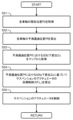
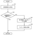
図14は、位置信頼度Daに基づくフィルタリング処理及びそれに関連する処理を示すフローチャートである。このフローチャートの処理は、車両1の走行中に、図10に示すフローチャートの処理と並行して所定の時間ステップ毎に繰り返し実行される。
Figure 14 is a flowchart showing filtering processing based on the position reliability Da and related processing. The processing of this flowchart is repeatedly executed at predetermined time steps in parallel with the processing of the flowchart shown in Figure 10 while the
図14では、位置信頼度Daが閾値Dathより高い場合(ステップS42;Yes)には、処理はリターンに進む。一方、位置信頼度Daが閾値Dath以下の場合(ステップS42;No)には、処理はステップS61に進む。 In FIG. 14, if the position reliability Da is higher than the threshold Dath (step S42; Yes), the process proceeds to return. On the other hand, if the position reliability Da is equal to or lower than the threshold Dath (step S42; No), the process proceeds to step S61.
ステップS61において、ECU70は、前方路面データに対してLPFを適用する処理(フィルタリング処理)を実行する。このLPFは、位置信頼度Daが低いことに起因して含まれる可能性の高い高周波成分を減衰させるために適した強さ及びカットオフ周波数を有するように構成されている。
In step S61, the
なお、前方路面データの取得は次のように行うことができる。すなわち、前方路面データは、例えば、上述のステップS33の処理によって時間ステップ毎にばね下変位マップ200から取得される予測通過位置Pfのばね下変位Zuを所定区間に渡って記憶したばね下変位Zuのデータとして取得されてもよい。あるいは、例えば、車両1の現在位置P0に対して進行方向Tdの前方に位置する所定区間(予測通過位置Pfを含む区間)内のばね下変位Zuのデータと進行方向Tdに沿って移動する車輪2の各位置への到達予想時刻とを関連付けた時系列データが、前方路面データとして取得されてもよい。
The forward road surface data can be acquired as follows. That is, the forward road surface data may be acquired, for example, as data of unsprung displacement Zu, which is obtained by storing the unsprung displacement Zu of the predicted passing position Pf acquired from the
前方路面データに対して上記フィルタリング処理を施すと、前方路面データの位相に遅れが生じる。この位相遅れは、適用されるLPFに応じて定まる時定数が大きいほど大きくなる。そこで、ステップS62において、ECU70は、フィルタリング処理において適用されたLPFの時定数に応じた前方路面データの位相遅れを相殺するようにプレビュー時間tpを増加させる。具体的には、プレビュー時間tpは、適用されるLPFの時定数分だけ長くなるように修正される。このため、プレビュー時間tpは、当該時定数が大きいほど長くなるように修正される。
When the above-mentioned filtering process is performed on the forward road surface data, a delay occurs in the phase of the forward road surface data. This phase delay becomes larger the larger the time constant determined according to the applied LPF. Therefore, in step S62, the
付け加えると、図14に示す処理と組み合わされる例では、ステップS34(図10参照)におけるプレビュー制御の要求制御量Xpv(目標制御力Fc_t)の算出は、上記フィルタリング処理後の前方路面データを用いて行われる。また、用いられるプレビューゲインGpvは基本ゲインGpv0である。さらに、ステップS62の処理によって修正されたプレビュー時間tpが用いられてもよい。 In addition, in an example combined with the processing shown in FIG. 14, the required control amount Xpv (target control force Fc_t) of the preview control in step S34 (see FIG. 10) is calculated using the forward road surface data after the above-mentioned filtering processing. The preview gain Gpv used is the basic gain Gpv0. Furthermore, the preview time tp corrected by the processing of step S62 may be used.
以上説明したフィルタリング処理によれば、要求制御量Xpvの算出の基礎となるばね下変位Zuのデータ(前方路面データ)に対してLPFが適用される。このような手法によっても、位置信頼度Daが低いためにプレビュー制御による制振効果に懸念がある場合に、プレビュー制御を抑制できるようになる。 According to the filtering process described above, the LPF is applied to the data of the unsprung displacement Zu (forward road surface data) that is the basis for calculating the required control amount Xpv. This method also makes it possible to suppress the preview control when there are concerns about the vibration damping effect of the preview control due to low position reliability Da.
より詳細には、位置信頼度Daが低いために前方路面データに対して高周波成分が多く含まれていた場合であっても、そのような高周波成分を適切に減衰又は除去したうえで、要求制御量Xpvを算出できる。このため、そのような高周波成分が多いことに起因してプレビュー制御の実行に伴うばね上構造体5の振動悪化が生じる可能性が高くなることを抑制できる。
More specifically, even if the forward road surface data contains a large number of high-frequency components due to a low position reliability Da, such high-frequency components can be appropriately attenuated or removed before calculating the required control amount Xpv. This makes it possible to suppress the increased possibility of the vibration of the sprung
また、フィルタリング処理に付随して実行されるステップS62の処理によれば、適用されたLPFの時定数に応じた前方路面データの位相遅れを相殺するようにプレビュー時間tpが増やされる。これにより、前方路面データの位相と、当該前方路面データに基づく要求制御量Xpvに対応する制御力Fcをアクチュエータ3Aが発生させるタイミングの位相とのずれがLPFの追加に起因して生じることを抑制できる。これにより、当該位相のずれに起因する乗り心地性能の悪化を抑制できる。
In addition, according to the processing of step S62 executed in conjunction with the filtering process, the preview time tp is increased so as to offset the phase delay of the front road surface data according to the time constant of the applied LPF. This makes it possible to prevent a shift in phase between the phase of the front road surface data and the phase of the timing at which the
また、図14に示すフィルタリング処理の例では、前方路面データに対してLPFが適用されている。ここで、高周波成分の多い前方路面データに基づいて要求制御量Xpvが算出されると、要求制御量Xpvに含まれる高周波成分も多くなる。そこで、フィルタリング処理は、前方路面データに代え、要求制御量Xpvに対してLPFを適用する処理であってもよい。このような例であっても、図14に示す処理と同様の効果が得られる。 In addition, in the example of the filtering process shown in FIG. 14, an LPF is applied to the front road surface data. Here, when the required control amount Xpv is calculated based on the front road surface data that contains a lot of high-frequency components, the high-frequency components contained in the required control amount Xpv also increase. Therefore, the filtering process may be a process in which an LPF is applied to the required control amount Xpv instead of the front road surface data. Even in such an example, the same effect as the process shown in FIG. 14 can be obtained.
1-4-6.制御処理の変形例
位置信頼度Daに基づく制御処理は、上述の「ゲイン変更処理(図11参照)」と「フィルタリング処理(図14参照)」とを組み合わせて実行されてもよい。
1-4-6. Modifications of the Control Process The control process based on the position reliability Da may be executed by combining the above-mentioned "gain change process (see FIG. 11)" and "filtering process (see FIG. 14)."
2.実施の形態2
次に説明される実施の形態2は、位置信頼度Daに代えて車速Vに基づいてプレビュー制御が抑制される点において、上述した実施の形態1と相違している。
2. Second embodiment
A second embodiment described next differs from the first embodiment described above in that the preview control is suppressed based on the vehicle speed V instead of the position reliability Da.
GNSS受信機等の位置センサ40を利用して取得される車両1の自己位置情報の誤差(位置誤差)は、車速Vが低い時に大きくなり易い。これは、車速Vが低いと、方位角、スリップ角、及び速度の誤差が大きくなり易いためである。
The error (position error) in the
付け加えると、車輪2が全く同じ経路を通過したとしても、車速Vが低い場合には車速Vが高い場合と比べて、路面データマップ上の路面変位関連値のデータの細かい凹凸又はノイズ成分を抽出し易くなる。その結果、車速Vが低い場合に取得される路面変位関連値には、路面データマップの生成及び更新の際の路面変位関連値の取得に用いられる周波数帯(例えば、ステップS14及びS15で用いられる0.3~10Hz)よりも高い周波成分が含まれる可能性が高まり、高周波振動の増加を招き得る。 In addition, even if the wheel 2 travels the exact same route, it is easier to extract small irregularities or noise components from the data of the road surface displacement-related values on the road surface data map when the vehicle speed V is low compared to when the vehicle speed V is high. As a result, the road surface displacement-related values acquired when the vehicle speed V is low are more likely to contain frequency components higher than the frequency band (e.g., 0.3 to 10 Hz used in steps S14 and S15) used to acquire the road surface displacement-related values when generating and updating the road surface data map, which may lead to an increase in high-frequency vibrations.
そこで、実施の形態2における「制御処理」では、ECU70は、車速Vが所定の閾値Vth2(第2閾値)以下の場合には、車速Vが閾値Vth2より高い場合と比べて抑制された態様でプレビュー制御を実行する。具体的には、ECU70は、車速Vが閾値Vth2以下の場合には、車速Vが閾値Vth2より高い場合と比べてプレビューゲインGpvを小さくする。
Therefore, in the "control process" in the second embodiment, when the vehicle speed V is equal to or less than a predetermined threshold value Vth2 (second threshold value), the
図15は、車速Vに基づくゲイン変更処理を示すフローチャートである。このフローチャートの処理は、車両1の走行中に、図10に示すフローチャートの処理と並行して、所定の時間ステップ毎に繰り返し実行される。
Figure 15 is a flowchart showing the gain change process based on the vehicle speed V. The process of this flowchart is executed repeatedly at predetermined time steps while the
図15では、ECU70は、まずステップS71において、車速Vを取得する。次いで、ステップS72において、ECU70は、取得した車速Vが閾値Vth2より高いか否かを判定する。その結果、この判定結果がYesの場合(車速V>閾値Vth2)には、処理はステップS43に進む。一方、当該判定結果がNoの場合(車速V≦閾値Vth2)には、処理はステップS73に進む。
In FIG. 15, the
ステップS73において、ECU70は、プレビューゲインGpvとして、基本ゲインGpv0より小さい抑制ゲインGpv1を選択する。図16(A)及び16(B)は、それぞれ、ステップS73における抑制ゲインGpv1の決定手法の例を説明するための図である。
In step S73, the
まず、図16(A)に示すように、抑制ゲインGpv1は、基本ゲインGpv0よりも小さい固定値であってもよい。また、図16(B)に示すように、抑制ゲインGpv1は、車速Vが低いほど小さくなるように決定されてもよい。付け加えると、抑制ゲインGpv1は、車速Vが低くなるにつれ、ゼロにまで減らされてもよい。 First, as shown in FIG. 16(A), the suppression gain Gpv1 may be a fixed value smaller than the basic gain Gpv0. Also, as shown in FIG. 16(B), the suppression gain Gpv1 may be determined to be smaller as the vehicle speed V becomes lower. In addition, the suppression gain Gpv1 may be reduced to zero as the vehicle speed V becomes lower.
以上説明したように、実施の形態2によれば、プレビューゲインGpvの変更を利用して、車速Vが閾値Vth2以下の場合には、車速Vが閾値Vth2より高い場合と比べて抑制された態様でプレビュー制御が実行される。このような手法によっても、車両1の自己位置情報の取得誤差が大きい状況下においてプレビュー制御が修正されずに実行される場合と比べて、プレビュー制御の実行に起因するばね上構造体5の振動悪化を抑制できる。このため、プレビュー制御の実行に起因する乗り心地の違和感を抑制できる。付け加えると、車速Vを利用する実施の形態2によれば、位置信頼度Daを利用する実施の形態1と比べてECU70の演算負荷を低減しつつ、上述のようにプレビュー制御を抑制できる。
As described above, according to the second embodiment, when the vehicle speed V is equal to or less than the threshold value Vth2, the preview control is executed in a more suppressed manner than when the vehicle speed V is higher than the threshold value Vth2, by utilizing the change in the preview gain Gpv. Even with this method, it is possible to suppress the deterioration of vibration of the sprung
実施の形態2における車速Vに基づく制御処理は、上述の「ゲイン変更処理(図15参照)」に代え、あるいはそれとともに、「フィルタリング処理(図14参照)」を組み合わせて実行されてもよい。 The control process based on the vehicle speed V in the second embodiment may be performed in combination with the "filtering process (see FIG. 14)" instead of or in addition to the above-mentioned "gain change process (see FIG. 15)."
また、車速Vに基づくゲイン変更処理は、図13に示す処理のように、FBゲインγの変更を伴って実行されてもよい。更に付け加えると、ステップS52において、FBゲインγをゲインγ1に上げるタイミングは、プレビューゲインGpvを抑制ゲインGpv1に下げるタイミングと必ずしも同じでなくてもよい。具体的には、ゲインγ1へのFBゲインγの増加は、プレビューゲインGpvを抑制ゲインGpv1に下げる際の車速値(すなわち、閾値Vth2)よりも低い車速値にまで車速Vが下がった時に実行されてもよい。 The gain change process based on the vehicle speed V may be performed with a change in the FB gain γ, as in the process shown in FIG. 13. In addition, in step S52, the timing at which the FB gain γ is increased to gain γ1 may not necessarily be the same as the timing at which the preview gain Gpv is reduced to the suppression gain Gpv1. Specifically, the increase in the FB gain γ to gain γ1 may be performed when the vehicle speed V has decreased to a vehicle speed value lower than the vehicle speed value (i.e., the threshold value Vth2) at which the preview gain Gpv is reduced to the suppression gain Gpv1.
3.実施の形態3
次に説明される実施の形態3は、位置信頼度Da及び車速Vに基づいてプレビュー制御が抑制される点において、上述した実施の形態1と相違している。
3. Third embodiment
A third embodiment described next differs from the first embodiment described above in that the preview control is suppressed based on the position reliability Da and the vehicle speed V.
具体的には、実施の形態3における「制御処理」では、ECU70は、位置信頼度Daが閾値Dath以下であること、及び、車速Vが閾値Vth2以下であることのうちの少なくとも一方の条件が満たされる場合には、位置信頼度Daが閾値Dathより高く且つ車速Vが閾値Vth2より高い場合と比べて抑制された態様でプレビュー制御を実行する。具体的には、ECU70は、上記少なくとも一方の条件が満たされる場合には、位置信頼度Daが閾値Dathより高く且つ車速Vが閾値Vth2より高い場合と比べてプレビューゲインGpvを小さくする。
Specifically, in the "control process" in the third embodiment, when at least one of the conditions that the position reliability Da is equal to or less than the threshold Dath and the vehicle speed V is equal to or less than the threshold Vth2 is satisfied, the
図17は、位置信頼度Da及び車速Vに基づくゲイン変更処理を示すフローチャートである。このフローチャートの処理は、車両1の走行中に、図10に示すフローチャートの処理と並行して、所定の時間ステップ毎に繰り返し実行される。
Figure 17 is a flowchart showing the gain change process based on the position reliability Da and the vehicle speed V. The process of this flowchart is repeatedly executed at predetermined time steps while the
図17では、まず、ステップS41及びS71において、位置信頼度Da及び車速Vが順に取得される。そして、位置信頼度判定(ステップS42)及び車速判定(ステップS72)の結果が共にYesの場合には、処理はステップS43に進む。一方、位置信頼度判定及び車速判定の何れか一方の結果がNoの場合には、ステップS81に進む。なお、図17では表されていないが、位置信頼度判定及び車速判定の結果が共にNoである場合に処理がステップS81に進む処理が行われてもよい。 In FIG. 17, first, in steps S41 and S71, the position reliability Da and the vehicle speed V are acquired in order. Then, if the results of both the position reliability determination (step S42) and the vehicle speed determination (step S72) are Yes, the process proceeds to step S43. On the other hand, if the results of either the position reliability determination or the vehicle speed determination are No, the process proceeds to step S81. Although not shown in FIG. 17, the process may proceed to step S81 if the results of both the position reliability determination and the vehicle speed determination are No.
ステップS81において、ECU70は、プレビューゲインGpvとして、基本ゲインGpv0より小さい抑制ゲインGpv1を選択する。具体的には、抑制ゲインGpv1は、基本ゲインGpv0よりも小さい固定値であってもよい。また、抑制ゲインGpv1は、例えば図12(B)及び16(B)に示すような手法で、位置信頼度Da及び車速Vの少なくとも一方が低いほど小さくなるように決定されてもよい。この際、抑制ゲインGpv1は、ゼロにまで減らされてもよい。
In step S81, the
以上説明した実施の形態3によれば、プレビュー制御を抑制すべきか否かの判定のために、位置信頼度Da及び車速Vの双方が利用される。このように位置信頼度Da及び車速Vを利用することにより、車両1の自己位置情報の取得誤差が生じている可能性が高い状況をより正確に判断でき、プレビュー制御の抑制をより適切に行えるようになる。
According to the third embodiment described above, both the position reliability Da and the vehicle speed V are used to determine whether or not preview control should be suppressed. By using the position reliability Da and the vehicle speed V in this manner, it is possible to more accurately determine a situation in which an acquisition error in the
実施の形態3における位置信頼度Da及び車速Vに基づく制御処理は、上述の「ゲイン変更処理(図17参照)」に代え、あるいはそれとともに、「フィルタリング処理(図14参照)」を組み合わせて実行されてもよい。 The control process based on the position reliability Da and the vehicle speed V in the third embodiment may be performed in combination with the "filtering process (see FIG. 14)" instead of or in addition to the above-mentioned "gain change process (see FIG. 17)."
4.他の実施の形態
上述した実施の形態1~3においては、プレビュー制御(及びフィードバック制御)は、車両1の4つの車輪2(すなわち、全輪)を対象として行われた。しかしながら、プレビュー制御(及びフィードバック制御)の対象となる車輪(制御対象輪)は、必ずしも全輪に限られず、例えば、左右前輪のみ、又は左右後輪のみであってもよい。
4. Other Embodiments In the above-described first to third embodiments, the preview control (and feedback control) is performed on the four wheels 2 (i.e., all wheels) of the
1 車両
2 車輪
3 サスペンション
3A アクチュエータ
4 ばね下構造体
5 ばね上構造体
10 車両制御システム
20 車両状態センサ
30 認識センサ
40 位置センサ
50 通信装置
60 走行装置
70 電子制御ユニット(ECU)
100 マップ管理システム
REFERENCE SIGNS
100 Map Management System
Claims (10)
前記アクチュエータを制御することにより、車両のばね上構造体の振動を低減するプレビュー制御を実行する電子制御ユニットと、
を備える車両用サスペンション制御装置であって、
前記電子制御ユニットは、
前記車両の自己位置情報を取得する位置取得処理と、
路面の上下方向の変位に関連する路面変位関連値を位置と関連付けてマップ化した路面データマップから、現在時刻からプレビュー時間後の前記制御対象輪の予測通過位置における路面変位関連値を取得する路面情報取得処理と、
前記自己位置情報の信頼度を算出する信頼度算出処理と、
前記予測通過位置における路面変位関連値に基づいて前記プレビュー制御を実行する制御処理と、
を実行し、
前記制御処理において、前記電子制御ユニットは、前記信頼度が第1閾値以下の場合には、前記信頼度が前記第1閾値より高い場合と比べて抑制された態様で前記プレビュー制御を実行し、
前記制御処理は、フィルタリング処理を含み、
前記フィルタリング処理は、前記信頼度が前記第1閾値以下の場合に、前記予測通過位置を含む前方路面における前記路面変位関連値のデータ若しくは当該データに基づく前記プレビュー制御の要求制御量に対してローパスフィルタを適用する処理である
ことを特徴とする車両用サスペンション制御装置。 An actuator for controlling a suspension stroke of a controlled wheel;
an electronic control unit that controls the actuator to execute a preview control for reducing vibration of a sprung structure of a vehicle;
A vehicle suspension control device comprising:
The electronic control unit includes:
A position acquisition process for acquiring self-position information of the vehicle;
a road surface information acquisition process for acquiring a road surface displacement-related value at a predicted passing position of the control target wheel after a preview time from a current time from a road surface data map in which a road surface displacement-related value related to a vertical displacement of the road surface is associated with a position and mapped;
A reliability calculation process for calculating the reliability of the self-location information;
a control process for executing the preview control based on a road surface displacement related value at the predicted passing position;
Run
In the control process, when the reliability is equal to or less than a first threshold, the electronic control unit executes the preview control in a more suppressed manner than when the reliability is higher than the first threshold.
The control process includes a filtering process,
The filtering process is a process of applying a low-pass filter to data of the road surface displacement-related value on the road surface ahead including the predicted passing position or to a requested control amount of the preview control based on the data, when the reliability is equal to or less than the first threshold value.
A vehicle suspension control device comprising:
ことを特徴とする請求項1に記載の車両用サスペンション制御装置。 2. The vehicle suspension control device according to claim 1, wherein the control process includes a gain change process for reducing a control gain included in the required control amount of the preview control when the reliability is equal to or lower than the first threshold value, compared to when the reliability is higher than the first threshold value.
前記アクチュエータを制御することにより、車両のばね上構造体の振動を低減するプレビュー制御を実行する電子制御ユニットと、
を備える車両用サスペンション制御装置であって、
前記電子制御ユニットは、
前記車両の車速を取得する処理と、
前記車両の自己位置情報を取得する位置取得処理と、
路面の上下方向の変位に関連する路面変位関連値を位置と関連付けてマップ化した路面データマップから、現在時刻からプレビュー時間後の前記制御対象輪の予測通過位置における路面変位関連値を取得する路面情報取得処理と、
前記予測通過位置における路面変位関連値に基づいて前記プレビュー制御を実行する制御処理と、
を実行し、
前記制御処理において、前記電子制御ユニットは、前記車速が第2閾値以下の場合には、前記車速が前記第2閾値より高い場合と比べて抑制された態様で前記プレビュー制御を実行し、
前記制御処理は、フィルタリング処理を含み、
前記フィルタリング処理は、前記車速が前記第2閾値以下の場合に、前記予測通過位置を含む前方路面における前記路面変位関連値のデータ若しくは当該データに基づく前記プレビュー制御の要求制御量に対してローパスフィルタを適用する処理である
ことを特徴とする車両用サスペンション制御装置。 An actuator for controlling a suspension stroke of a controlled wheel;
an electronic control unit that controls the actuator to execute a preview control for reducing vibration of a sprung structure of a vehicle;
A vehicle suspension control device comprising:
The electronic control unit includes:
A process of acquiring a vehicle speed of the vehicle;
A position acquisition process for acquiring self-position information of the vehicle;
a road surface information acquisition process for acquiring a road surface displacement-related value at a predicted passing position of the control target wheel after a preview time from a current time from a road surface data map in which a road surface displacement-related value related to a vertical displacement of the road surface is associated with a position and mapped;
a control process for executing the preview control based on a road surface displacement related value at the predicted passing position;
Run
In the control process, when the vehicle speed is equal to or less than a second threshold, the electronic control unit executes the preview control in a more suppressed manner than when the vehicle speed is higher than the second threshold.
The control process includes a filtering process,
The filtering process is a process of applying a low-pass filter to data of the road surface displacement-related value on the road surface ahead including the predicted passing position or to a requested control amount of the preview control based on the data, when the vehicle speed is equal to or less than the second threshold value.
A vehicle suspension control device comprising:
ことを特徴とする請求項3に記載の車両用サスペンション制御装置。 4. The vehicle suspension control device according to claim 3, characterized in that the control process includes a gain change process for reducing a control gain included in the required control amount of the preview control when the vehicle speed is equal to or lower than the second threshold value compared to when the vehicle speed is higher than the second threshold value.
前記アクチュエータを制御することにより、車両のばね上構造体の振動を低減するプレビュー制御を実行する電子制御ユニットと、
を備える車両用サスペンション制御装置であって、
前記電子制御ユニットは、
前記車両の車速を取得する処理と、
前記車両の自己位置情報を取得する位置取得処理と、
路面の上下方向の変位に関連する路面変位関連値を位置と関連付けてマップ化した路面データマップから、現在時刻からプレビュー時間後の前記制御対象輪の予測通過位置における路面変位関連値を取得する路面情報取得処理と、
前記自己位置情報の信頼度を算出する信頼度算出処理と、
前記予測通過位置における路面変位関連値に基づいて前記プレビュー制御を実行する制御処理と、
を実行し、
前記制御処理において、前記電子制御ユニットは、前記信頼度が第1閾値以下であること、及び、前記車速が第2閾値以下であることのうちの少なくとも一方の条件が満たされる場合には、前記信頼度が前記第1閾値より高く且つ前記車速が前記第2閾値より高い場合と比べて抑制された態様で前記プレビュー制御を実行し、
前記制御処理は、フィルタリング処理を含み、
前記フィルタリング処理は、前記少なくとも一方の条件が満たされる場合に、前記予測通過位置を含む前方路面における前記路面変位関連値のデータ若しくは当該データに基づく前記プレビュー制御の要求制御量に対してローパスフィルタを適用する処理である
ことを特徴とする車両用サスペンション制御装置。 An actuator for controlling a suspension stroke of a controlled wheel;
an electronic control unit that controls the actuator to execute a preview control for reducing vibration of a sprung structure of a vehicle;
A vehicle suspension control device comprising:
The electronic control unit includes:
A process of acquiring a vehicle speed of the vehicle;
A position acquisition process for acquiring self-position information of the vehicle;
a road surface information acquisition process for acquiring a road surface displacement-related value at a predicted passing position of the control target wheel after a preview time from a current time from a road surface data map in which a road surface displacement-related value related to a vertical displacement of the road surface is associated with a position and mapped;
A reliability calculation process for calculating the reliability of the self-location information;
a control process for executing the preview control based on a road surface displacement related value at the predicted passing position;
Run
In the control process, when at least one of the conditions that the reliability is equal to or less than a first threshold and the vehicle speed is equal to or less than a second threshold is satisfied, the electronic control unit executes the preview control in a more suppressed manner than when the reliability is higher than the first threshold and the vehicle speed is higher than the second threshold,
The control process includes a filtering process,
The filtering process is a process of applying a low-pass filter to data of the road surface displacement-related value on the road surface ahead including the predicted passing position or to a requested control amount of the preview control based on the data when at least one of the conditions is satisfied.
A vehicle suspension control device comprising:
ことを特徴とする請求項5に記載の車両用サスペンション制御装置。 6. The vehicle suspension control device according to claim 5, wherein the control process includes a gain change process for reducing a control gain included in the required control amount of the preview control when at least one of the conditions is satisfied, compared to a case in which the reliability is higher than the first threshold value and the vehicle speed is higher than the second threshold value.
ことを特徴とする請求項2又は6に記載の車両用サスペンション制御装置。 7. The vehicle suspension control device according to claim 2, wherein, when the control gain is reduced in the gain change process, the electronic control unit reduces the control gain as the reliability decreases.
ことを特徴とする請求項4又は6に記載の車両用サスペンション制御装置。 7. The vehicle suspension control device according to claim 4 , wherein, when the control gain is reduced in the gain change process, the electronic control unit reduces the control gain as the vehicle speed decreases.
前記ゲイン変更処理において前記制御ゲインを小さくする場合、前記電子制御ユニットは、前記フィードバック制御のフィードバックゲインを大きくする
ことを特徴とする請求項2、4、6、7、又は8に記載の車両用サスペンション制御装置。 the electronic control unit controls the actuator to perform feedback control for reducing vibration of the sprung structure in addition to the preview control;
9. The vehicle suspension control device according to claim 2, 4 , 6 , 7 or 8 , wherein the electronic control unit increases a feedback gain of the feedback control when the control gain is reduced in the gain change process.
ことを特徴とする請求項1、3、又は5に記載の車両用サスペンション制御装置。 The vehicle suspension control device according to claim 1, 3, or 5, characterized in that in the filtering process, the electronic control unit increases the preview time so as to offset a phase delay of the data of the road surface displacement related value according to a time constant of the low - pass filter.
Priority Applications (1)
| Application Number | Priority Date | Filing Date | Title |
|---|---|---|---|
| JP2021163996A JP7635692B2 (en) | 2021-10-05 | 2021-10-05 | Vehicle suspension control device |
Applications Claiming Priority (1)
| Application Number | Priority Date | Filing Date | Title |
|---|---|---|---|
| JP2021163996A JP7635692B2 (en) | 2021-10-05 | 2021-10-05 | Vehicle suspension control device |
Publications (2)
| Publication Number | Publication Date |
|---|---|
| JP2023054955A JP2023054955A (en) | 2023-04-17 |
| JP7635692B2 true JP7635692B2 (en) | 2025-02-26 |
Family
ID=85986303
Family Applications (1)
| Application Number | Title | Priority Date | Filing Date |
|---|---|---|---|
| JP2021163996A Active JP7635692B2 (en) | 2021-10-05 | 2021-10-05 | Vehicle suspension control device |
Country Status (1)
| Country | Link |
|---|---|
| JP (1) | JP7635692B2 (en) |
Families Citing this family (4)
| Publication number | Priority date | Publication date | Assignee | Title |
|---|---|---|---|---|
| JP2025030906A (en) * | 2023-08-24 | 2025-03-07 | トヨタ自動車株式会社 | Suspension Control System |
| JP2025030719A (en) * | 2023-08-24 | 2025-03-07 | トヨタ自動車株式会社 | Suspension Control System |
| JP2025035781A (en) * | 2023-09-04 | 2025-03-14 | トヨタ自動車株式会社 | Suspension Control System |
| JP2026039645A (en) * | 2024-08-23 | 2026-03-09 | トヨタ自動車株式会社 | Vehicle control system, map management system, and parameter map |
Citations (5)
| Publication number | Priority date | Publication date | Assignee | Title |
|---|---|---|---|---|
| JP2007147564A (en) | 2005-11-30 | 2007-06-14 | Aisin Aw Co Ltd | Image recognition device and method thereof, and own vehicle position recognition device and method |
| JP2008049862A (en) | 2006-08-25 | 2008-03-06 | Toyota Motor Corp | Vehicle behavior control device |
| US20180154723A1 (en) | 2013-03-15 | 2018-06-07 | ClearMotion, Inc. | Self-driving vehicle with integrated active suspension |
| JP2019509926A (en) | 2016-03-02 | 2019-04-11 | クリアモーション アクイジション 1 エルエルシー | Active suspension control of vehicle plant based on vehicle position |
| JP2021138241A (en) | 2020-03-04 | 2021-09-16 | トヨタ自動車株式会社 | Vehicular preview vibration damping control device and vehicular preview vibration damping control method |
-
2021
- 2021-10-05 JP JP2021163996A patent/JP7635692B2/en active Active
Patent Citations (5)
| Publication number | Priority date | Publication date | Assignee | Title |
|---|---|---|---|---|
| JP2007147564A (en) | 2005-11-30 | 2007-06-14 | Aisin Aw Co Ltd | Image recognition device and method thereof, and own vehicle position recognition device and method |
| JP2008049862A (en) | 2006-08-25 | 2008-03-06 | Toyota Motor Corp | Vehicle behavior control device |
| US20180154723A1 (en) | 2013-03-15 | 2018-06-07 | ClearMotion, Inc. | Self-driving vehicle with integrated active suspension |
| JP2019509926A (en) | 2016-03-02 | 2019-04-11 | クリアモーション アクイジション 1 エルエルシー | Active suspension control of vehicle plant based on vehicle position |
| JP2021138241A (en) | 2020-03-04 | 2021-09-16 | トヨタ自動車株式会社 | Vehicular preview vibration damping control device and vehicular preview vibration damping control method |
Also Published As
| Publication number | Publication date |
|---|---|
| JP2023054955A (en) | 2023-04-17 |
Similar Documents
| Publication | Publication Date | Title |
|---|---|---|
| JP7635692B2 (en) | Vehicle suspension control device | |
| JP7605072B2 (en) | Map management method and map management system | |
| JP7544010B2 (en) | Map data, map update method, vehicle control method, and vehicle control system | |
| JP2025035781A (en) | Suspension Control System | |
| JP7647463B2 (en) | VEHICLE POSITION ESTIMATION METHOD AND VEHICLE CONTROL SYSTEM | |
| US12485717B2 (en) | Suspension control system | |
| US12565074B2 (en) | Suspension control system | |
| JP7544009B2 (en) | Map data, map update method, vehicle control method, and vehicle control system | |
| JP7666261B2 (en) | Map data, map update method, vehicle control method, and vehicle control system | |
| JP7582144B2 (en) | Vehicle suspension control device, vehicle control system, and vehicle suspension control method | |
| US20260061796A1 (en) | Vehicle damping control method and damping control system | |
| JP7615990B2 (en) | Vehicle control method and vehicle control system | |
| US20260054537A1 (en) | Vehicle control system | |
| JP2026028610A (en) | Vehicle control method and position reliability calculation method | |
| KR20260035066A (en) | Vehicle damping control method and damping control system | |
| WO2026042400A1 (en) | Vehicle control system, map management system, and parameter map | |
| US20260056027A1 (en) | Vehicle management system | |
| JP2026048214A (en) | Control map management method and management system | |
| KR20260035098A (en) | Management method and management system for control map | |
| US20260056021A1 (en) | Control system | |
| KR20260026426A (en) | Vehicle control system and navigation system |
Legal Events
| Date | Code | Title | Description |
|---|---|---|---|
| A621 | Written request for application examination |
Free format text: JAPANESE INTERMEDIATE CODE: A621 Effective date: 20240214 |
|
| A977 | Report on retrieval |
Free format text: JAPANESE INTERMEDIATE CODE: A971007 Effective date: 20241010 |
|
| A131 | Notification of reasons for refusal |
Free format text: JAPANESE INTERMEDIATE CODE: A131 Effective date: 20241022 |
|
| A521 | Request for written amendment filed |
Free format text: JAPANESE INTERMEDIATE CODE: A523 Effective date: 20241024 |
|
| TRDD | Decision of grant or rejection written | ||
| A01 | Written decision to grant a patent or to grant a registration (utility model) |
Free format text: JAPANESE INTERMEDIATE CODE: A01 Effective date: 20250114 |
|
| A61 | First payment of annual fees (during grant procedure) |
Free format text: JAPANESE INTERMEDIATE CODE: A61 Effective date: 20250127 |
|
| R150 | Certificate of patent or registration of utility model |
Ref document number: 7635692 Country of ref document: JP Free format text: JAPANESE INTERMEDIATE CODE: R150 |