JP7635663B2 - Wiring Fixture - Google Patents
Wiring Fixture Download PDFInfo
- Publication number
- JP7635663B2 JP7635663B2 JP2021116880A JP2021116880A JP7635663B2 JP 7635663 B2 JP7635663 B2 JP 7635663B2 JP 2021116880 A JP2021116880 A JP 2021116880A JP 2021116880 A JP2021116880 A JP 2021116880A JP 7635663 B2 JP7635663 B2 JP 7635663B2
- Authority
- JP
- Japan
- Prior art keywords
- wiring
- light
- gripping
- fixture according
- movable
- Prior art date
- Legal status (The legal status is an assumption and is not a legal conclusion. Google has not performed a legal analysis and makes no representation as to the accuracy of the status listed.)
- Active
Links
- 238000010586 diagram Methods 0.000 description 16
- 238000009434 installation Methods 0.000 description 6
- 238000000034 method Methods 0.000 description 5
- 239000013307 optical fiber Substances 0.000 description 4
- 230000004048 modification Effects 0.000 description 2
- 238000012986 modification Methods 0.000 description 2
- 239000012790 adhesive layer Substances 0.000 description 1
- 238000005452 bending Methods 0.000 description 1
- 238000005516 engineering process Methods 0.000 description 1
- 238000000253 optical time-domain reflectometry Methods 0.000 description 1
Images


Landscapes
- Light Guides In General And Applications Therefor (AREA)
- Installation Of Indoor Wiring (AREA)
Description
本発明は、配線固定具に関する。 The present invention relates to a wiring fixture.
近年、配線を固定する配線固定治具が開発されている。例えば、特許文献1では、光ファイバーケーブルを把持する固定治具の一面に接着層を有することで、例えば、屋内の壁や、車内のフロントパネルに接着することが可能な配線固定治具が開示されている。
In recent years, wiring fixing jigs for fixing wiring have been developed. For example,
しかし、特許文献1に記載した技術では、例えば、作業者が配線の直線性を保ちつつ配線固定治具を用いて配線を固定する場合に、予め設置場所を定めておく必要が生じ、また、作業者は、配線固定治具を用いて固定された配線が直線性を保てているか否かを確認することが困難になり得る。
However, with the technology described in
そこで、本発明は、上記問題に鑑みてなされたものであり、本発明の目的とするところは、固定された配線が直線性を保てているか否かを作業者により容易に判断させることが可能な、新規かつ改良された配線固定具を提供することにある。 The present invention was made in consideration of the above problems, and the object of the present invention is to provide a new and improved wiring fixture that allows the worker to easily determine whether the fixed wiring is maintaining its linearity.
上記課題を解決するために、本発明のある観点によれば、配線を固定する配線固定具であって、前記配線を把持する構造を有し、前記配線が把持されている状態の前記配線の把持位置における前記配線の軸方向に対して平行な光を発する発光体を支持し、前記配線固定具より前記発光体が発する光の進行方向の反対側に設置された他の配線固定具が有する発光体が発した光を受ける受光的、を有する配線把持部、を備える、配線固定具が提供される。 In order to solve the above problems, according to one aspect of the present invention, there is provided a wiring fixture for fixing a wiring, the wiring fixture comprising a wiring gripping portion having a structure for gripping the wiring, supporting a light emitter that emits light parallel to the axial direction of the wiring at the gripping position of the wiring when the wiring is gripped, and a light receiving element that receives light emitted by a light emitter of another wiring fixture installed on the opposite side of the wiring fixture in the traveling direction of the light emitted by the light emitter.
任意の設置場所に固定される固定部、を更に備え、前記配線把持部の位置は、前記固定部に対して相対的に可変であってもよい。 The device may further include a fixing part that is fixed to any installation location, and the position of the wiring gripping part may be variable relative to the fixing part.
前記配線把持部と前記固定部の間に設けられ、前記固定部に対して移動可能な可動部、
を更に備えてもよい。
a movable portion provided between the wire gripping portion and the fixed portion and movable relative to the fixed portion;
may further comprise:
前記配線把持部の位置は、前記配線の軸方向に交差する方向に可変であってもよい。 The position of the wiring gripping portion may be variable in a direction intersecting the axial direction of the wiring.
前記可動部は、前記固定部に対してスライドにより移動可能であってもよい。 The movable part may be movable relative to the fixed part by sliding.
前記配線把持部は、前記可動部に対してスライドにより移動可能であってもよい。 The wiring gripping portion may be movable by sliding relative to the movable portion.
前記可動部は、前記配線把持部との連結面または前記固定部との連結面のうち少なくともいずれか一方に長穴を有してもよい。 The movable part may have a long hole on at least one of the connection surface with the wiring gripping part or the connection surface with the fixed part.
前記可動部は、前記配線把持部との連結面において、高さ方向に沿って形成された長穴を有し、前記固定部との連結面において、水平方向に沿って形成された長穴を有してもよい。 The movable part may have a long hole formed along the height direction on the connection surface with the wiring gripping part, and a long hole formed along the horizontal direction on the connection surface with the fixed part.
前記配線把持部は、前記受光的の周囲に沿って形成された凸状構造を有してもよい。 The wiring gripping portion may have a convex structure formed along the periphery of the light receiving element.
前記受光的の中心軸と同一直線上に中心軸を有する穴を有する遮光部、を更に備えてもよい。 The device may further include a light-shielding portion having a hole with a central axis aligned with the central axis of the light-receiving element.
前記発光体が発する光は、レーザー光であってもよい。 The light emitted by the light emitter may be laser light.
前記配線把持部は、前記発光体が取付けられる穴を有してもよい。 The wiring gripping portion may have a hole in which the light emitter is attached.
前記配線把持部は、前記発光体、を更に備えてもよい。 The wiring gripping portion may further include the light emitter.
以上説明したように本発明によれば、固定された配線が直線性を保てているか否かを作業者により容易に判断させることが可能な、新規かつ改良された配線固定具を提供することが可能である。 As described above, the present invention provides a new and improved wiring fixture that allows an operator to easily determine whether the fixed wiring is maintaining its linearity.
以下に添付図面を参照しながら、本発明の好適な実施の形態について詳細に説明する。なお、本明細書及び図面において、実質的に同一の機能構成を有する構成要素については、同一の符号を付することにより重複説明を省略する。 The preferred embodiment of the present invention will be described in detail below with reference to the attached drawings. Note that in this specification and the drawings, components having substantially the same functional configuration are designated by the same reference numerals to avoid redundant description.
また、複数ある配線固定具1をそれぞれ配線固定具1A、1Bおよび1Cのように区別して表現する場合があるが、各配線固定具1を特に区別する必要がない場合は、単に配線固定具1と称する。
In addition, the
<<1.配線固定具の概要>>
本発明の一実施形態は、固定された配線が直線性を保てているか否かを作業者により容易に判断させることを可能とする配線固定具に関する。以下、図1を参照し、本実施形態に係る配線固定具の概要を説明する。
<<1. Overview of wiring fixtures>>
An embodiment of the present invention relates to a wire fastener that enables an operator to easily determine whether or not a fixed wire maintains linearity. Hereinafter, an overview of the wire fastener according to the present embodiment will be described with reference to FIG.
近年、配線の直線性を保ちつつ配線を設置場所に固定することが望ましい状況がある。例えば、構造物(例えば、船舶)の歪や温度分布を測定する方法の一例として、光ファイバーケーブルを当該構造物に敷設し、光ファイバー中の後方散乱を測定するBOTDR(Brillouin Optical Time Domain Reflectometry)がある。BOTDRによる測定に際して、光ファイバーケーブルは、構造物の形状に沿って直線性を保ちつつ固定されることが望ましい場合がある。 In recent years, there are situations where it is desirable to fix wiring to an installation location while maintaining the linearity of the wiring. For example, one method for measuring the distortion and temperature distribution of a structure (e.g., a ship) is Brillouin Optical Time Domain Reflectometry (BOTDR), which lays an optical fiber cable in the structure and measures backscattering in the optical fiber. When measuring with BOTDR, it is sometimes desirable to fix the optical fiber cable in place while maintaining linearity along the shape of the structure.
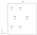
図1は、本実施形態に係る配線固定具1の概要を説明するための説明図である。本実施形態に係る配線固定具1は、配線Wを任意の位置で固定する固定治具である。例えば、図1に示すように、配線固定具1A、配線固定具1Bおよび配線固定具1Cのように複数の箇所で配線Wを固定することで配線Wを撓ませずに固定することができる。なお、図1および図2は、概要を説明する便宜上、配線固定具1を簡略化した図であり、実際の配線固定具1の外観とは異なる。
Figure 1 is an explanatory diagram for explaining the outline of the
また、本実施形態に係る配線固定具1は、それぞれ配線Wの把持位置における配線Wの軸方向に対して平行な光Lを発する発光体101を支持し、ある配線固定具1より、光の進行方向の反対側に設置された他の配線固定具1が有する発光体101が発した光を受ける受光的105を有する。
The
例えば、図1において、配線固定具1Aは、配線Wの把持位置における配線Wの軸方向に対して平行な光Lを発する発光体101Aを支持し、配線固定具1Aにより支持された発光体101Aが発する光Lの進行方向の反対側に設置された配線固定具1Bが有する発光体101Bが発した光Lを受ける受光的105Aを有する。
For example, in FIG. 1, the
作業者は、配線固定具1Bが支持する発光体101Bが発する光Lが、配線固定具1Aが有する受光的105Aに当るように、配線固定具1Aまたは配線固定具1Bの位置を調整する。
The worker adjusts the position of the
また、作業者が配線固定具1を設置したい経路に障害物がある状況も想定される。その場合、従来では、作業者は、障害物が存在しない経路を改めて選定し、改めて選定した経路に配線固定具1を設置して配線を固定する必要があった。このように、作業者は当初に計画した経路に配線を固定できない状況が生じ得た。
It is also possible that there may be an obstacle on the route along which the worker wants to install the
また、作業者は、配線固定具1を設置した経路に障害物が存在した場合、当該障害物の影響を受ける箇所のみ配線固定具1をずらして設置して配線を固定する状況も生じ得た。
In addition, if an obstacle is present in the path where the
図2は、障害物Aが存在する状況の一例を説明するための説明図である。例えば、作業者は、障害物Aが存在することで配線固定具1Bを設置できない状況がある。このような状況では、作業者は、障害物Aを避けた位置に配線固定具1Bを設置して配線Wを固定するが、同時に配線Wの直線性を保つことが困難になり得る。
Figure 2 is an explanatory diagram for explaining an example of a situation in which an obstacle A is present. For example, there may be a situation in which the worker is unable to install the
そこで、本実施形態に係る配線固定具1は、このような障害物Aが配線固定具1を設置したい経路間にあった際においても、配線Wの直線性を保ちつつ配線Wを固定することが可能である。以下、図3を参照して、本実施形態に係る配線固定具1を説明する。
Therefore, the
<2.構成例>
<2.1.配線固定具1の全体構成>
図3は、本実施形態に係る配線固定具1の構成例を説明するための説明図である。本実施形態に係る配線固定具1は、配線把持部10と、固定部20と、可動部30と、を備える。本明細書では、図3に示すように配線Wの軸方向をZ方向とし、配線固定具1の横幅方向をX方向、配線固定具1の高さ方向をY方向として説明する。
2. Configuration example
<2.1. Overall configuration of
Fig. 3 is an explanatory diagram for explaining a configuration example of the
配線把持部10は、把持部本体100、発光体101、プレートPL、ネジS1およびネジS2を含む。把持部本体100、プレートPLおよびネジS1は、配線Wを把持する構造として機能する。発光体101は、把持部本体100に支持されている。発光体101は、直進性を有する光を発することが望ましい。発光体101が発する直進性を有する光は、例えば、レーザー光であってもよい。また、配線把持部10は、把持部本体100とネジS2により可動部30を挟持することにより、可動部30に連結されている。詳細は後述する通り、配線把持部10の位置は、固定部20に対して相対的に可変である。また、配線把持部10の位置は、配線の軸方向に交差する方向に可変である。
The
固定部20は、固定部本体200および固定用ネジS3を含み、任意の設置場所に固定される。例えば、固定部本体200は図3に示したように中空のコの字形状を有する。固定部20は、固定部本体200の中空部分に固定物Fが配置された状態で固定部本体200と固定用ネジS3により固定物Fを挟持することにより、固定物Fに固定される。すなわち、固定部20は、固定物Fが存在する任意の設置場所に固定され得る。
The fixing
可動部30は、配線把持部10と固定部20との間に設けられ、固定部20に対して移動可能である。なお、以下の説明では、配線把持部10に連結される可動部30の面を把持部連結面と表現し、固定部20に連結される可動部30の面を固定部連結面と表現する場合がある。
The
配線把持部10および可動部30は、ネジS2により連結される。また、固定部20および可動部30は、ネジS4により連結される。
The
以下、図4~図6を参照し、配線把持部10、固定部20および可動部30の構成例を順次説明する。なお、以下の説明では、図3に示す配線固定具1の方向を正面図として説明する。
Below, with reference to Figures 4 to 6, examples of the configuration of the
<2.2.配線把持部10の構成例>
図4Aは、本実施形態に係る把持部本体100の正面図である。本実施形態に係る配線把持部10は、配線を把持する構造を有し、配線が把持されている状態の配線の把持位置における配線の軸方向に対して平行な光を発する発光体101を支持する。配線を把持する構造は、例えば、図4Aに示すような直線状に形成された溝Nであってもよい。
2.2. Configuration example of
4A is a front view of the gripper
また、把持部本体100は、発光体101を支持する方法の一例として、発光体101が取り付けられる穴を有していてもよい。この場合、発光体101は、当該穴に嵌め込まれ把持部本体100により支持される。または、把持部本体100は、発光体101を支持する方法の他の例として、発光体101を予め備えていてもよい。
The
また、把持部本体100は、ネジ穴H1およびネジ穴H2Aを有する。作業者は、図3に示したプレートPLを介してネジS1をネジ穴H1に取り付ける。これにより、配線把持部10は、プレートPLにより挟み込むことで配線を把持することが可能である。
The
また、作業者は、図3に示した可動部30を介してネジS2をネジ穴H2Aに取り付ける。なお、図4Aに示すネジ穴H1およびネジ穴H2Aは、それぞれ任意の数であってもよい。
The worker also attaches the screw S2 to the screw hole H2A via the
図4Bは、本実施形態に係る把持部本体100の背面図である。配線把持部10は、配線固定具1より光の進行方向の反対側に設置された他の配線固定具が有する発光体が発した光を受ける受光的105を有する。例えば、配線把持部10は、発光体101が発する光の中心軸と同一の中心軸を有する受光的105を有する。これにより、作業者は、発光体101が発する光が前方にある配線把持部10の受光的105に当っていることを確認することで、配線の直線性を保てていることをより容易に判断することが可能である。
Figure 4B is a rear view of the gripping unit
なお、本実施形態に係る受光的105の形状、大きさまたは位置は図4Bに示す例に限定されない。受光的105の形状、大きさまたは位置は、発光体101の性能や求める精度に応じて適宜変更されてもよい。
Note that the shape, size, or position of the
以上、本実施形態に係る配線把持部10の構成例を説明した。続いて、図5を参照し、本実施形態に係る固定部20の構成例を説明する。
The above describes an example of the configuration of the
<2.3.固定部20の構成例>
図5は、本実施形態に係る固定部本体200の平面図である。固定部本体200は、図5に示すように、ネジ穴H3Bおよびネジ穴H4Bを有する。作業者は、図3に示した固定用ネジS3をネジ穴H3Bに取り付ける。固定部20は、図3に示した固定用ネジS3により固定物Fを挟み込むことで配線固定具1を任意の設置場所に固定する。
2.3. Configuration example of fixed
Fig. 5 is a plan view of the fixing part
作業者は、図3に示した可動部30を介して、ネジS4をネジ穴H4Bに取り付ける。
The worker installs the screw S4 into the screw hole H4B via the
<2.4.可動部30の構成例>
図6Aは、本実施形態に係る可動部30の平面図である。可動部30は、固定部連結面において、水平方向(X方向)に沿って形成された長穴H4Cを有する。長穴H4Cの形状は、図6Aでは長方形である例を示しているが、本実施形態に係る長穴H4Cは係る例に限定されない。長穴H4Cの形状は、長方形の四隅に丸みがあってもよく、可動部30が可動できる範囲で任意の形状であってもよい。また、長穴H4Cの大きさは、連結に用いるネジのネジ部径に併せて適宜変更されてもよい。
2.4. Configuration example of the
6A is a plan view of the
図6Bは、固定部20と可動部30とが連結された状態を示す説明図である。図6Bに示すように、可動部30は、固定部20に対して水平方向(X方向)のスライドにより移動可能である。これにより、作業者は、障害物を水平方向に避けて配線把持部10の位置を調整できる。
Figure 6B is an explanatory diagram showing the state in which the fixed
図7Aは、本実施形態に係る可動部30の側面図である。可動部30は、把持部連結面において、高さ方向(Y方向)に沿って形成された長穴H2Cを有する。なお、可動部30は、把持部連結面または上述した固定部連結面のうち少なくともいずれか一方に長穴を有していてもよい。
Figure 7A is a side view of the
図7Bは、配線把持部10と可動部30とが連結された状態を示す説明図である。図7Bに示すように配線把持部10は、可動部30に対して高さ方向(Y方向)のスライドにより移動可能である。これにより、作業者は、障害物を高さ方向に避けて配線把持部10の位置を調整できる。
Figure 7B is an explanatory diagram showing the state in which the
以上、本実施形態に係る配線固定具1の構成例を説明した。以上説明したように、本実施形態に係る配線固定具1によれば、作業者は、障害物の有無や障害物の位置に応じて、配線固定具1の位置を調整することが可能である。そして、作業者は、配線把持部10が支持する発光体101の発する光が前方の配線固定具1が備える配線把持部10の受光的105に当たるように配線把持部10又は可動部30の位置を調整する。これにより、作業者は、配線の直線性を保ちつつ配線を固定することが可能である。
The above describes an example of the configuration of the
なお、より高い精度で配線の直線性を保ちつつ配線を固定するためには、作業者は、受光的105に当たる光が受光的105の中心軸の方向から光が入射されたか否かを判別することが望ましい。このような受光的105の中心軸の方向から光が入射されたことを判別する一手法として、受光的に入射された光の真円の度合いを確認する方法がある。例えば、受光的105の中心軸とのなす角が大きい方向から光が入射された場合、受光的105に入射された光は楕円形として作業者に視認され得る。したがって、作業者は、受光的に入射された光の形状から光の入射された方向を判別可能になり得る。
In order to fix the wiring while maintaining the linearity of the wiring with higher accuracy, it is desirable for the worker to determine whether the light hitting the
また、受光的に当たる光が受光的の中心軸の方向から光が入射されたか否かを判別する方法の他の例として配線把持部10の構成に創意工夫がなされてもよい。以下、配線把持部10の構成の創意工夫に関し、図8~図10を参照して、配線把持部10の変形例を説明する。
As another example of a method for determining whether light striking the light-receiving element is incident from the direction of the center axis of the light-receiving element, the configuration of the
<<3.変形例>>
<3.1.第1の変形例>
図8は、配線把持部10の第1の変形例を説明するための説明図である。第1の変形例に係る配線把持部10は受光的105の中心軸と同一直線上に中心軸を有する穴を有する遮光部110を備えてもよい。これにより、遮光部110は、受光的105に向かう光Lのうち、受光的105の中心軸と光のなす角が所定値以上である光Lを遮光する。この結果、作業者は、発光体101が発する光が前方にある配線把持部10の受光的105に当っているか否かを確認することで、配線の直線性を保てているか否かを判断し得る。なお、図8では、3つの配線把持部10が配線Wを一定間隔ごとに設置する一例を示しているが、配線把持部10が配線Wを把持する間隔は必ずしも一定でなくてもよい。
<<3. Modified Examples>>
<3.1. First Modification>
FIG. 8 is an explanatory diagram for explaining a first modified example of the
<3.2.第2の変形例>
図9は、配線把持部10の第2の変形例を説明するための説明図である。第2の変形例に係る配線把持部10は、受光的105の周囲に沿って形成された凸状構造Cを有していてもよい。凸状構造Cは、受光的105に向かう光Lのうち、受光的105の中心軸とのなす角が所定値以上である光Lを遮光する。
3.2. Second Modification
9 is an explanatory diagram for explaining a second modified example of the
また、配線把持部10は、受光的105を配線把持部10の溝部として有していてもよい。これにより、配線把持部10の溝部としてある受光的105は、受光的105の中心軸とのなす角が所定値未満である光Lのみが当たる。この結果、作業者は、発光体101が発する光が前方にある配線把持部10の受光的105に当っているか否かを確認することで、配線の直線性を保てているか否かを判断し得る。
The
<3.3.第3の変形例>
図10は、配線把持部10の第3の変形例を説明するための説明図である。配線把持部10は、配線Wの軸方向と直交する2面でそれぞれ発光体101を支持し、受光的105を有していてもよい。
3.3. Third modified example
10 is an explanatory diagram for explaining a third modified example of the
この場合、配線把持部10が備える2つの発光体101は双方向に光Lを発する。そして、作業者は、双方向から入射される光Lが各々に対応する2つの受光的105に当るように配線把持部10の位置を調整する。これにより、配線固定具1は、より高い精度で配線Wの直線性を保ちつつ配線Wを固定し得る。
In this case, the two
<<4.補足>>
以上、添付図面を参照しながら本発明の好適な実施形態について詳細に説明したが、本発明はかかる例に限定されない。本発明の属する技術の分野における通常の知識を有する者であれば、特許請求の範囲に記載された技術的思想の範疇内において、各種の変更例または修正例に想到し得ることは明らかであり、これらについても、当然に本発明の技術的範囲に属するものと了解される。
<<4. Supplementary Information>>
Although the preferred embodiment of the present invention has been described in detail above with reference to the accompanying drawings, the present invention is not limited to such an example. It is clear that a person having ordinary knowledge in the technical field to which the present invention pertains can conceive of various modified or altered examples within the scope of the technical ideas described in the claims, and it is understood that these also naturally belong to the technical scope of the present invention.
例えば、本明細書では、本実施形態に係る配線把持部10が受光的105を備える例を説明したが、本実施形態に係る配線固定具1は、作業者に一定間隔で配置され、当該間隔の所定の位置にある配線を受光的として利用してもよい。この場合、発光体101は、配線Wが直線性を保つことが可能な方向に向けて光を発するように配線把持部10により支持されてもよい。
For example, in the present specification, an example has been described in which the
また、本実施形態に係る配線固定具1は、可動部30のような可動機構を必ずしも有していなくてもよい。
In addition, the
また、本明細書では、配線把持部10の位置が固定部20に対して並進方向に可変である一例を説明したが、配線把持部10の位置は、固定部20に対して回転方向に可変であってもよい。これにより、作業者は、配線把持部10の位置をより高い自由度で調整し得る。
In addition, although an example has been described in this specification in which the position of the
1 配線固定具
10 配線把持部
100 把持部本体
101 発光体
105 受光的
20 固定部
200 固定部本体
30 可動部
1
Claims (13)
前記配線を把持する構造を有し、前記配線が把持されている状態の前記配線の把持位置における前記配線の軸方向に対して平行な光を発する発光体を支持し、
前記配線固定具より前記発光体が発する光の進行方向の反対側に設置された他の配線固定具が有する発光体が発した光を受ける受光的、を有する配線把持部、
を備える、配線固定具。 A wiring fixture for fixing wiring,
a light-emitting body that has a structure for gripping the wiring and that emits light parallel to an axial direction of the wiring at a gripping position of the wiring in a state in which the wiring is gripped;
a wiring gripping portion having a light receiving portion for receiving light emitted by a light emitter of another wiring fastener disposed on the opposite side of the wiring fastener in the traveling direction of the light emitted by the light emitter;
A wiring fixture comprising:
を更に備え、
前記配線把持部の位置は、前記固定部に対して相対的に可変である、
請求項1に記載の配線固定具。 A fixed part that can be fixed to any desired location;
Further comprising:
The position of the wire gripping portion is variable relative to the fixed portion.
The wiring fixture according to claim 1 .
を更に備える、
請求項2に記載の配線固定具。 a movable portion provided between the wire gripping portion and the fixed portion and movable relative to the fixed portion;
Further comprising:
The wiring fixture according to claim 2 .
請求項3に記載の配線固定具。 The position of the wire gripping portion is variable in a direction intersecting the axial direction of the wire.
The wiring fixture according to claim 3.
請求項4に記載の配線固定具。 The movable part is movable by sliding relative to the fixed part.
The wiring fixture according to claim 4.
請求項4または請求項5に記載の配線固定具。 The wiring gripping portion is movable by sliding relative to the movable portion.
The wiring fixture according to claim 4 or 5.
前記配線把持部との連結面または前記固定部との連結面のうち少なくともいずれか一方に長穴を有する、
請求項5または請求項6に記載の配線固定具。 The movable part is
A long hole is provided on at least one of a surface for connecting to the wire gripping portion and a surface for connecting to the fixing portion.
The wiring fixture according to claim 5 or 6.
前記配線把持部との連結面において、高さ方向に沿って形成された長穴を有し、
前記固定部との連結面において、水平方向に沿って形成された長穴を有する、
請求項7に記載の配線固定具。 The movable part is
A long hole is formed along a height direction on a connection surface with the wire gripping portion,
A long hole is formed in the horizontal direction on the connection surface with the fixed portion.
The wiring fixture according to claim 7.
前記受光的の周囲に沿って形成された凸状構造を有する、
請求項1から請求項8までのうちいずれか一項に記載の配線固定具。 The wiring gripping portion is
A convex structure is formed along the periphery of the light receiving portion.
The wiring fixture according to any one of claims 1 to 8.
を更に備える、
請求項1から請求項9までのうちいずれか一項に記載の配線固定具。 a light-shielding portion having a hole with a central axis aligned with the central axis of the light-receiving portion;
Further comprising:
The wiring fixture according to any one of claims 1 to 9.
請求項1から請求項10までのうちいずれか一項に記載の配線固定具。 The light emitted by the light emitter is a laser light.
The wiring fixture according to any one of claims 1 to 10.
前記発光体が取付けられる穴を有する、
請求項1から請求項11までのうちいずれか一項に記載の配線固定具。 The wiring gripping portion is
The light emitter has a hole in which it is mounted.
The wiring fixture according to any one of claims 1 to 11.
前記発光体、
を更に備える、
請求項1から請求項11までのうちいずれか一項に記載の配線固定具。 The wiring gripping portion is
The light emitter,
Further comprising:
The wiring fixture according to any one of claims 1 to 11.
Priority Applications (1)
| Application Number | Priority Date | Filing Date | Title |
|---|---|---|---|
| JP2021116880A JP7635663B2 (en) | 2021-07-15 | 2021-07-15 | Wiring Fixture |
Applications Claiming Priority (1)
| Application Number | Priority Date | Filing Date | Title |
|---|---|---|---|
| JP2021116880A JP7635663B2 (en) | 2021-07-15 | 2021-07-15 | Wiring Fixture |
Publications (2)
| Publication Number | Publication Date |
|---|---|
| JP2023013013A JP2023013013A (en) | 2023-01-26 |
| JP7635663B2 true JP7635663B2 (en) | 2025-02-26 |
Family
ID=85129396
Family Applications (1)
| Application Number | Title | Priority Date | Filing Date |
|---|---|---|---|
| JP2021116880A Active JP7635663B2 (en) | 2021-07-15 | 2021-07-15 | Wiring Fixture |
Country Status (1)
| Country | Link |
|---|---|
| JP (1) | JP7635663B2 (en) |
Citations (5)
| Publication number | Priority date | Publication date | Assignee | Title |
|---|---|---|---|---|
| JP2000056143A (en) | 1998-08-10 | 2000-02-25 | Mitsubishi Heavy Ind Ltd | Jig for optical fiber fixation, and fixation structure and tunnel for optical fiber |
| JP2001296112A (en) | 2000-04-13 | 2001-10-26 | Dai Ichi High Frequency Co Ltd | Strain observation device |
| JP2002048675A (en) | 2000-08-01 | 2002-02-15 | Fujikura Ltd | Optical fiber sensor |
| JP2014172350A (en) | 2013-03-12 | 2014-09-22 | Dainippon Screen Mfg Co Ltd | Printing device and method for adjusting arrangement position thereof |
| CN107407305A (en) | 2015-03-27 | 2017-11-28 | 康普技术有限责任公司 | Hanger for installing cables |
-
2021
- 2021-07-15 JP JP2021116880A patent/JP7635663B2/en active Active
Patent Citations (6)
| Publication number | Priority date | Publication date | Assignee | Title |
|---|---|---|---|---|
| JP2000056143A (en) | 1998-08-10 | 2000-02-25 | Mitsubishi Heavy Ind Ltd | Jig for optical fiber fixation, and fixation structure and tunnel for optical fiber |
| JP2001296112A (en) | 2000-04-13 | 2001-10-26 | Dai Ichi High Frequency Co Ltd | Strain observation device |
| JP2002048675A (en) | 2000-08-01 | 2002-02-15 | Fujikura Ltd | Optical fiber sensor |
| JP2014172350A (en) | 2013-03-12 | 2014-09-22 | Dainippon Screen Mfg Co Ltd | Printing device and method for adjusting arrangement position thereof |
| CN107407305A (en) | 2015-03-27 | 2017-11-28 | 康普技术有限责任公司 | Hanger for installing cables |
| US20190221143A1 (en) | 2015-03-27 | 2019-07-18 | Commscope Technologies Llc | Hanger for mounting cables |
Also Published As
| Publication number | Publication date |
|---|---|
| JP2023013013A (en) | 2023-01-26 |
Similar Documents
| Publication | Publication Date | Title |
|---|---|---|
| EP2813804B1 (en) | Inside-diameter measurement device | |
| ATE519092T1 (en) | LASER-ASSISTED COORDINATE MEASURING APPARATUS AND LASER-ASSISTED COORDINATE MEASURING METHOD | |
| US20150108376A1 (en) | Distance Measuring Photoelectric Sensor And Method For Controlling Light Projection Spot Thereof | |
| US7885500B2 (en) | Apparatus and method for adjusting an optical rotating data transmission device | |
| JP7635663B2 (en) | Wiring Fixture | |
| KR20200093615A (en) | Car headlamp and method | |
| JP2011198537A (en) | Lamp tool for vehicle | |
| JP2019149778A5 (en) | Image reader and image forming device | |
| US7277811B1 (en) | Calibration apparatus and process | |
| US20070258694A1 (en) | Test apparatus and cable guide unit | |
| US20200344392A1 (en) | Image detection system | |
| JP2014196954A (en) | Photoelectric encoder | |
| BR0005375A (en) | Optoelectronic layout | |
| JP2019063750A (en) | Air purge unit | |
| JP2008107130A (en) | Laser head for laser marking machine | |
| DE69406365D1 (en) | Fiber optic light source device with adjustable light beam | |
| JP6253255B2 (en) | Light source unit | |
| JP2008091171A (en) | Mounting for multiple-optical-axis photoelectric sensor and attaching structure for the multiple-optical-axis photoelectric sensor | |
| US20120188773A1 (en) | Encoding Device and a Method of Encoding | |
| US11934012B2 (en) | Optical adjustment apparatus, optical adjustment method, and optical device | |
| JPH1074433A (en) | Fixture | |
| CN219352007U (en) | Novel laser alignment detecting system | |
| WO2017221890A1 (en) | Optical fiber arrangement method, optical fiber arrangement apparatus, and system for measuring transmission characteristics of optical fiber | |
| JP3597927B2 (en) | Laser beam and optical fiber alignment device | |
| JP3046408B2 (en) | Light sensor |
Legal Events
| Date | Code | Title | Description |
|---|---|---|---|
| A621 | Written request for application examination |
Free format text: JAPANESE INTERMEDIATE CODE: A621 Effective date: 20240508 |
|
| A977 | Report on retrieval |
Free format text: JAPANESE INTERMEDIATE CODE: A971007 Effective date: 20241028 |
|
| A131 | Notification of reasons for refusal |
Free format text: JAPANESE INTERMEDIATE CODE: A131 Effective date: 20241112 |
|
| TRDD | Decision of grant or rejection written | ||
| A01 | Written decision to grant a patent or to grant a registration (utility model) |
Free format text: JAPANESE INTERMEDIATE CODE: A01 Effective date: 20250114 |
|
| A61 | First payment of annual fees (during grant procedure) |
Free format text: JAPANESE INTERMEDIATE CODE: A61 Effective date: 20250127 |
|
| R150 | Certificate of patent or registration of utility model |
Ref document number: 7635663 Country of ref document: JP Free format text: JAPANESE INTERMEDIATE CODE: R150 |