JP7635561B2 - Occupant monitoring device - Google Patents
Occupant monitoring device Download PDFInfo
- Publication number
- JP7635561B2 JP7635561B2 JP2021011622A JP2021011622A JP7635561B2 JP 7635561 B2 JP7635561 B2 JP 7635561B2 JP 2021011622 A JP2021011622 A JP 2021011622A JP 2021011622 A JP2021011622 A JP 2021011622A JP 7635561 B2 JP7635561 B2 JP 7635561B2
- Authority
- JP
- Japan
- Prior art keywords
- infrared light
- occupant
- vehicle
- driver
- housing
- Prior art date
- Legal status (The legal status is an assumption and is not a legal conclusion. Google has not performed a legal analysis and makes no representation as to the accuracy of the status listed.)
- Active
Links
- 238000012806 monitoring device Methods 0.000 title claims description 13
- 238000003384 imaging method Methods 0.000 claims description 12
- 230000001678 irradiating effect Effects 0.000 claims description 12
- 238000005286 illumination Methods 0.000 claims description 9
- 239000006059 cover glass Substances 0.000 description 6
- 230000002093 peripheral effect Effects 0.000 description 5
- 239000000463 material Substances 0.000 description 4
- 229920000515 polycarbonate Polymers 0.000 description 3
- 239000004417 polycarbonate Substances 0.000 description 3
- 229910052782 aluminium Inorganic materials 0.000 description 2
- XAGFODPZIPBFFR-UHFFFAOYSA-N aluminium Chemical compound [Al] XAGFODPZIPBFFR-UHFFFAOYSA-N 0.000 description 2
- 238000010586 diagram Methods 0.000 description 2
- 229910052751 metal Inorganic materials 0.000 description 2
- 239000002184 metal Substances 0.000 description 2
- 238000012544 monitoring process Methods 0.000 description 2
- 229920000122 acrylonitrile butadiene styrene Polymers 0.000 description 1
- 230000000903 blocking effect Effects 0.000 description 1
- 230000000694 effects Effects 0.000 description 1
- 230000004424 eye movement Effects 0.000 description 1
- 239000011521 glass Substances 0.000 description 1
- 239000004973 liquid crystal related substance Substances 0.000 description 1
- 230000003287 optical effect Effects 0.000 description 1
- 239000011347 resin Substances 0.000 description 1
- 229920005989 resin Polymers 0.000 description 1
Images


Landscapes
- Fittings On The Vehicle Exterior For Carrying Loads, And Devices For Holding Or Mounting Articles (AREA)
- Instrument Panels (AREA)
Description
本発明は、車両の乗員に赤外光を照射して乗員の挙動を撮像する乗員監視装置に関する。 The present invention relates to an occupant monitoring device that irradiates infrared light onto vehicle occupants to capture images of their behavior.
車両のフロントウインドシールドやコンバイナ等の反射透光部材を透過する実景(車両前方の風景)に重ねて、その反射透光部材に反射された表示光により虚像を生成して表示するヘッドアップディスプレイ装置は、車両の乗員(運転者)の視線移動を極力抑えつつ、乗員が所望する情報を虚像により提供することによって、安全で快適な車両運行に寄与する。 A head-up display device generates and displays a virtual image using display light reflected by a reflective translucent material, such as the vehicle's front windshield or combiner, which is superimposed on the actual scene (the scenery in front of the vehicle) that passes through the reflective translucent material. This contributes to safe and comfortable vehicle operation by providing the vehicle occupant (driver) with the information they desire through a virtual image while minimizing eye movement.
また、ヘッドアップディスプレイ装置には、反射透光部材に反射された赤外光を乗員に照射して撮像を行い、その撮像画像に基づいて乗員のよそ見、居眠り等の挙動の把握に供するモニタリングシステム(乗員監視装置)を搭載するものがある。 Some head-up display devices are also equipped with a monitoring system (occupant monitoring device) that captures images of occupants by shining infrared light reflected by a reflective, translucent member onto them, and uses the captured images to determine the occupant's behavior, such as looking away or falling asleep.
例えば特許文献1に記載のヘッドアップディスプレイ装置は、表示手段から発せられる可視光をコンバイナ部材にて運転者(利用者)に向けて反射して表示像を結像するものであるが、さらに、運転者に向けて赤外線を照射する赤外線照射手段と、表示手段から発せられる可視光をコンバイナ部材に向けて反射し、運転者及びコンバイナ部材にて反射される赤外線を透過するミラー部材と、ミラー部材を透過する赤外線を感受して運転者をそれぞれ異なる方向から撮像する複数の撮像手段と、撮像手段によって撮像された画像に基づいて運転者の目の位置を算出する画像処理手段とを備え、運転者の目の位置を精度良く算出することが可能となっている。
For example, the head-up display device described in
ところで、乗員監視装置が赤外光により乗員を撮像する場合、夜間等の車外が暗い環境下において反射透光部材に赤外光の光源が写り、赤い玉(点光源)として乗員に視認されることがある。このいわゆる玉見えによって、乗員は違和感を覚え、とりわけ運転者は運転中に煩わしさを感じるという問題があった。 However, when an occupant monitoring device captures an image of an occupant using infrared light, the infrared light source may be reflected by the reflective translucent material in a dark environment outside the vehicle, such as at night, and may be seen by the occupant as a red ball (point light source). This so-called "ball appearance" can cause the occupant to feel uncomfortable, and the driver in particular may find it annoying while driving.
本発明は、上記の事情に鑑みてなされたもので、反射透光部材で反射する赤外光が乗員に視認される事態の発生を抑制することができる乗員監視装置を提供することを課題としている。 The present invention was made in consideration of the above circumstances, and aims to provide an occupant monitoring device that can prevent infrared light reflected by a reflective translucent member from being visually recognized by an occupant.
上記課題を解決するために、本発明は、車両に設けられて可視光を透過させ赤外光を反射する反射透光部材に対し、赤外光を照射する赤外光照射手段と、前記反射透光部材に反射された赤外光により前記車両の乗員を撮像する撮像手段と、前記赤外光照射手段及び前記撮像手段を収容する筐体とを備え、前記赤外光照射手段は、前記乗員又は前記車両の他の乗員の視点位置から見て、前記反射透光部材における前記赤外光の反射位置が前記車両のヘッドライトの照射領域と重畳するように、前記筐体に設けられていることを特徴とする乗員監視装置を特徴とする。 In order to solve the above problems, the present invention provides an occupant monitoring device that includes an infrared light irradiating means for irradiating infrared light onto a reflective translucent member that is provided in a vehicle and transmits visible light and reflects infrared light, an imaging means for imaging an occupant of the vehicle using the infrared light reflected by the reflective translucent member, and a housing that houses the infrared light irradiating means and the imaging means, and the infrared light irradiating means is provided in the housing such that, when viewed from the viewpoint of the occupant or another occupant of the vehicle, the reflection position of the infrared light on the reflective translucent member overlaps with the illumination area of the headlights of the vehicle.
ここで、乗員の視点位置とは、車両のいずれかの乗員の視点(目の位置)として想定される位置で、乗員のシートポジションや体格を想定して定まる一定の空間領域に含まれる位置とすることができる。 Here, the occupant's viewpoint position is the position assumed to be the viewpoint (eye position) of any occupant in the vehicle, and can be a position included in a certain spatial area determined based on the occupant's seat position and physique.
前記赤外光照射手段は、前記乗員又は前記他の乗員の視点位置から見て、前記反射透光部材における前記赤外光の反射位置が前記ヘッドライトのロービームの照射領域と重畳するように、前記筐体に設けられてもよい。 The infrared light irradiation means may be provided on the housing such that, as viewed from the viewpoint of the occupant or the other occupant, the reflection position of the infrared light in the reflective translucent member overlaps with the illumination area of the low beam of the headlight.
また、前記赤外光照射手段は、前記乗員又は前記他の乗員の視点位置から見て、前記反射透光部材における前記赤外光の反射位置が、その反射輝度よりも高い照射輝度を有する前記照射領域の高輝度領域と重畳するように、前記筐体に設けられてもよい。 The infrared light irradiation means may be provided on the housing so that, when viewed from the viewpoint of the occupant or the other occupant, the reflection position of the infrared light in the reflective translucent member overlaps with a high-luminance area of the irradiation area having an irradiation luminance higher than the reflection luminance.
さらに、前記乗員は、前記車両の運転席に着座する運転者であってもよい。 Furthermore, the occupant may be a driver seated in the driver's seat of the vehicle.
本発明によれば、反射透光部材で反射する赤外光が乗員に視認される事態の発生を抑制することができるという効果を奏する。 The present invention has the effect of preventing the occurrence of a situation in which infrared light reflected by a reflective/translucent member is visible to an occupant.
本発明を実施するための形態について、図面に基づいて説明する。 The embodiment of the present invention will be described with reference to the drawings.
図1及び図2に示すように、本実施の形態に係る乗員監視装置を内蔵するヘッドアップディスプレイ装置(HUD)1は、車両2のフロントウインドシールド3の下方にあるインストルメントパネル4の内部に設けられ、フロントウインドシールド3の一部に可視光である表示光L1を投影する。表示光L1は、フロントウインドシールド3に反射されて虚像Vを生成し、ステアリングホイール5の後方の図示を略す運転席に着座する運転者Dにフロントウインドシールド3を透過する実景に重ねて虚像Vを視認させる。
1 and 2, a head-up display device (HUD) 1 incorporating an occupant monitoring device according to this embodiment is provided inside an
また、HUD1は、運転者Dの状態をモニターする機能を持ち、運転者Dに赤外光L2を照射して運転者Dを撮像する。
The
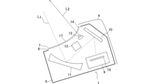
詳細には、HUD1は、黒色のABS樹脂等により成形されて外光の侵入が防止されたハウジング6に覆われて外部と区画され、ハウジング6にはポリカーボネート等からなる透明なカバーガラス7が取り付けられた開口部8が形成されている。ハウジング6の内部には、表示器ユニット9と、平面鏡10と、凹面鏡11と、赤外光照射ユニット12と、カメラ13とが保持・収容されている。
In detail, the
カバーガラス7は、図2に示すように、下方に凸に湾曲した四辺形板状を呈し、その周縁部(四辺の周辺部)には全周にわたって可視光を遮光する遮光部14が設けられている。遮光部14は、ポリカーボネート等の透明な基材に対し、黒色の印刷層が形成されてなる。
As shown in FIG. 2, the
表示器ユニット9は、光源及び液晶パネル等からなる表示器15が設けられ、表示器15から可視光である映像光(表示光L1)を投影表示する。平面鏡10は、平面部分を有するように成形されたガラスにアルミニウム等の金属や誘電体多層膜を蒸着してなり、可視光を単純に反射する。凹面鏡11は、凹面部分を有するように成形されたポリカーボネート等の樹脂にアルミニウム等の金属を蒸着してなり、可視光を拡大して反射する。
The
赤外光照射ユニット12は、図3に示すように、ハウジング6においてカバーガラス7の下方で遮光部14に対向するように、車両2の車幅方向中央側に設けられている。遮光部14の赤外光照射ユニット12が対向する部分には、赤外光を透過させる赤外光透過部16が設けられ(遮光部14のうち、赤外光透過部16の部分は、可視光を遮蔽して赤外光を透過させる黒色の印刷層からなり、それ以外の部分は、可視光及び赤外光を遮蔽する黒色の印刷層からなる。)、赤外光照射ユニット12は、発光ダイオード(LED)からなる光源(点光源)が発する赤外光(近赤外線)L2を赤外光透過部16を通してフロントウインドシールド3に向けて照射する。
3, the infrared
その際、運転者Dの視点位置(ここでは、設計上のアイボックス17内の任意の位置で、図1にはアイボックス17内の高さが異なる3つの視点位置を記載している。)から見て、フロントウインドシールド3における赤外光L2の反射位置(赤外光照射ユニット12の光源の光軸がフロントウインドシールド3と交わる位置)Rは、車両2のヘッドライト18の照射領域(ヘッドライト18の照射光が届く全ての領域)19の少なくとも一部(例えば、照射領域19における最高照度に対して80%の等照度曲線で囲まれた高照度領域)と重畳する(図1においては、車両2のヘッドライト18から路面上の照射領域19までの距離が車両2の寸法に比して長いことから、車両2の前方空間及び路面の一部について、破断線により図示を省略している。)。
At that time, as viewed from the viewpoint position of the driver D (here, any position within the designed
一方、カメラ13は、ハウジング6においてカバーガラス7の下方で赤外光透過部16に対向するように、車両2の車幅方向中央側、かつ、赤外光照射ユニット12の前方に設けられ、赤外照射ユニット12から照射される波長帯の赤外光L2に感度を有する撮像素子、及び、赤外光L2を透過してその撮像素子に結像させ得るレンズを備えて近赤外線画像を撮影する。
On the other hand, the
また、本実施形態の場合、ここでの詳細図示は省略するが、ハウジング6は、車幅方向と略直交(交差)する一対の周壁部を有しており、これら一対の周壁部のうち車両を左右に2等分する仮想中心ラインに近い側に位置する一周壁部(一方の周壁部)のやや内側となるハウジング6の空所に赤外光照射ユニット12及びカメラ13を設けた構成としている。なお、ここでのハウジング6は、4つの周壁部を備え、図2で図示された概ね車幅方向に沿う2つの周壁部は、前記一対の周壁部の各々の端部同士を繋ぐ立壁として構成される。
In the present embodiment, although detailed illustration is omitted here, the
HUD1において、表示器ユニット9からの表示光L1は、平面鏡10で反射され、次いで、凹面鏡11で拡大して反射され、カバーガラス7の遮光部14に囲まれた透明な中央部17を通過してフロントウインドシールド3に投影される。フロントウインドシールド3に投影された表示光L1は、運転者Dの側に拡大して反射され、虚像Vを生成してフロントウインドシールド3を透過する実景に重ねて運転者Dに表示する。
In the
一方、赤外光照射ユニット12からの赤外光L2は、カバーガラス7の遮光部14の赤外光透過部16を通過してフロントウインドシールド3に投影され、フロントウインドシールド3で運転者Dの側に反射されて運転者Dを照射する。そして、運転者Dに反射されると赤外光L2の一部は逆の経路を辿り、赤外光透過部16を通過してカメラ13に入射した赤外光L2により運転者Dが撮像される。この撮像は、虚像Vの表示中、定期的又は不定期的に行われ、その撮像画像に基づいて運転者Dのモニタリングが行われる。
On the other hand, the infrared light L2 from the infrared
本実施の形態に係るHUD1の乗員監視装置は、車両2に設けられて可視光を透過させ赤外光を反射するフロントウインドシールド3に対し、赤外光L2を照射する赤外光照射ユニット12と、フロントウインドシールド3に反射された赤外光L2により車両2の運転者Dを撮像するカメラ13と、赤外光照射ユニット12及びカメラ13を収容するハウジング6とを備え、赤外光照射ユニット12は、運転者Dの視点位置から見て、フロントウインドシールド3における赤外光L2の反射位置Rが車両2のヘッドライト18の照射領域19と重畳するように、ハウジング6に設けられている(収容されている)ので、車外が暗い環境下においてフロントウインドシールド3に赤外光照射ユニット12の光源が写り、背景が暗ければ赤い玉として運転者Dに視認されるような場合でも、ヘッドライト18を点灯していればその照射領域19が赤い玉に重畳し、赤い玉の背景が明るくなることにより、フロントウインドシールド3で反射する赤外光L2が乗員に視認される事態(玉見え)の発生を抑制することができる。
The occupant monitoring device of the
なお、赤外光照射ユニット12は、運転者Dの視点位置から見て、フロントウインドシールド3における赤外光L2の反射位置Rが車両2のヘッドライト18のロービームの照射領域と重畳するようにハウジング6に設けられていることが望ましく、これにより、玉見えの発生をヘッドライト18の点灯状態であれば常に(ハイビームの場合のみならずロービームの場合にも)抑制することができる。
It is preferable that the infrared
また、赤外光照射ユニット12は、運転者Dの視点位置から見て、フロントウインドシールド3における赤外光L2の反射位置Rが、その反射位置Rにおける赤外光L2の反射輝度よりも高い照射輝度を有する照射領域19の高輝度領域と重畳するようにハウジング6に設けられていることが望ましい。
In addition, it is desirable that the infrared
なお、ここでの反射輝度とは、前記光源から発せられる赤外光L2がフロントウインドシールド3で反射して運転者Dに照射される際のフロントウインドシールド3で反射する赤外光L2の輝度を意味する。照射領域19の照射輝度とは、ヘッドライト18の照射対象である路面等による反射光の輝度(背景輝度)であり、より具体的に言うと、ヘッドライト18が路面等を照らした際の路面等から反射して運転者Dから視認可能な路面等の輝度を意味する。そして、照射領域19の高輝度領域は、その照射輝度が赤外光L2の反射輝度よりも高いので、反射位置Rが当該高輝度領域と重畳することによって、玉見えの発生をより確実に抑制することができる。
The reflected luminance here means the luminance of the infrared light L2 reflected by the
以上、本発明を実施するための形態について例示したが、本発明の実施形態は上述したものに限られず、発明の趣旨を逸脱しない範囲で適宜変更等してもよい。 The above describes examples of embodiments of the present invention, but the embodiments of the present invention are not limited to those described above and may be modified as appropriate without departing from the spirit of the invention.
例えば、上記実施の形態では、車両のフロントウインドシールドを反射透光部材としたが、反射透光部材としてフロントウインドシールドに代えてコンバイナ等を用いてもよい。 For example, in the above embodiment, the vehicle's front windshield is used as a reflective translucent member, but a combiner or the like may be used as the reflective translucent member instead of the front windshield.
また、赤外光照射ユニット12は、車両2の運転席に着座する運転者Dではなく助手席や後部座席等に着座する運転者D以外の他の乗員の視点位置から見て、フロントウインドシールド3における赤外光L2の反射位置Rが車両2のヘッドライト18の照射領域19と重畳するようにハウジング6に設けられてもよい。
In addition, the infrared
2 車両
3 フロントウインドシールド(反射透光部材)
6 筐体(ハウジング)
12 赤外光照射ユニット(赤外光照射手段)
13 カメラ(撮像手段)
18 ヘッドライト
19 照射領域
D 運転者(乗員)
L2 赤外光
R 反射位置
2
6. Housing
12 Infrared light irradiation unit (infrared light irradiation means)
13 Camera (imaging means)
18
L 2 Infrared light R reflection position
Claims (4)
前記反射透光部材に反射された赤外光により前記車両の乗員を撮像する撮像手段と、
前記赤外光照射手段及び前記撮像手段を収容する筐体とを備え、
前記赤外光照射手段は、前記乗員又は前記車両の他の乗員の視点位置から見て、前記反射透光部材における前記赤外光の反射位置が前記車両のヘッドライトの照射領域と重畳するように、前記筐体に設けられていることを特徴とする乗員監視装置。 an infrared light irradiating means for irradiating infrared light onto a reflective transmissive member that is provided in the vehicle and transmits visible light and reflects infrared light;
an imaging means for imaging an occupant of the vehicle using infrared light reflected by the reflective light-transmitting member;
a housing that houses the infrared light irradiating means and the imaging means,
An occupant monitoring device characterized in that the infrared light irradiation means is provided in the housing so that, when viewed from the viewpoint of the occupant or another occupant of the vehicle, the reflection position of the infrared light in the reflective translucent member overlaps with the illumination area of the headlights of the vehicle.
Priority Applications (1)
| Application Number | Priority Date | Filing Date | Title |
|---|---|---|---|
| JP2021011622A JP7635561B2 (en) | 2021-01-28 | 2021-01-28 | Occupant monitoring device |
Applications Claiming Priority (1)
| Application Number | Priority Date | Filing Date | Title |
|---|---|---|---|
| JP2021011622A JP7635561B2 (en) | 2021-01-28 | 2021-01-28 | Occupant monitoring device |
Publications (2)
| Publication Number | Publication Date |
|---|---|
| JP2022115145A JP2022115145A (en) | 2022-08-09 |
| JP7635561B2 true JP7635561B2 (en) | 2025-02-26 |
Family
ID=82747974
Family Applications (1)
| Application Number | Title | Priority Date | Filing Date |
|---|---|---|---|
| JP2021011622A Active JP7635561B2 (en) | 2021-01-28 | 2021-01-28 | Occupant monitoring device |
Country Status (1)
| Country | Link |
|---|---|
| JP (1) | JP7635561B2 (en) |
Citations (3)
| Publication number | Priority date | Publication date | Assignee | Title |
|---|---|---|---|---|
| JP2004273180A (en) | 2003-03-06 | 2004-09-30 | Koito Mfg Co Ltd | Vehicle headlights |
| US20200183161A1 (en) | 2016-12-02 | 2020-06-11 | Lg Electronics Inc. | Head-up display for vehicle |
| JP2020170159A (en) | 2019-04-02 | 2020-10-15 | 東レ株式会社 | Multilayer laminate film for infrared detection system and infrared detection system using the same |
-
2021
- 2021-01-28 JP JP2021011622A patent/JP7635561B2/en active Active
Patent Citations (3)
| Publication number | Priority date | Publication date | Assignee | Title |
|---|---|---|---|---|
| JP2004273180A (en) | 2003-03-06 | 2004-09-30 | Koito Mfg Co Ltd | Vehicle headlights |
| US20200183161A1 (en) | 2016-12-02 | 2020-06-11 | Lg Electronics Inc. | Head-up display for vehicle |
| JP2020170159A (en) | 2019-04-02 | 2020-10-15 | 東レ株式会社 | Multilayer laminate film for infrared detection system and infrared detection system using the same |
Also Published As
| Publication number | Publication date |
|---|---|
| JP2022115145A (en) | 2022-08-09 |
Similar Documents
| Publication | Publication Date | Title |
|---|---|---|
| CN111301166B (en) | Projection equipment | |
| KR102252759B1 (en) | Display device for superimposing a virtual image on the user's field of view | |
| JP4895324B2 (en) | Head-up display device | |
| CN113022448B (en) | display system | |
| JP6706802B2 (en) | Display system, electronic mirror system, and moving body including the same | |
| JP6945150B2 (en) | Display system | |
| CN110914113B (en) | Imaging device and display device for vehicle | |
| JP6697751B2 (en) | Vehicle display system, electronic mirror system and moving body | |
| JP7619356B2 (en) | Vehicle display device | |
| US20240210691A1 (en) | Holographic projection device | |
| JP7492670B2 (en) | Vehicle display device | |
| JP7491075B2 (en) | Vehicle display device | |
| JP6697747B2 (en) | Display system, electronic mirror system and moving body | |
| JP6927178B2 (en) | Vehicle display device | |
| JP7635561B2 (en) | Occupant monitoring device | |
| JP2024007661A (en) | heads up display device | |
| JP7230750B2 (en) | Display device | |
| JP7631876B2 (en) | Passenger monitoring device and vehicle display device | |
| JP7476747B2 (en) | Vehicle display device | |
| JP7504387B2 (en) | Imaging and display system | |
| JP2021119065A (en) | Head-up display device | |
| WO2023112908A1 (en) | Display device | |
| WO2019017157A1 (en) | Imaging device and vehicular display device | |
| JP2020154027A (en) | Display device | |
| JP2004228887A (en) | Display device for vehicle |
Legal Events
| Date | Code | Title | Description |
|---|---|---|---|
| A621 | Written request for application examination |
Free format text: JAPANESE INTERMEDIATE CODE: A621 Effective date: 20231117 |
|
| A977 | Report on retrieval |
Free format text: JAPANESE INTERMEDIATE CODE: A971007 Effective date: 20240821 |
|
| A131 | Notification of reasons for refusal |
Free format text: JAPANESE INTERMEDIATE CODE: A131 Effective date: 20240905 |
|
| TRDD | Decision of grant or rejection written | ||
| A01 | Written decision to grant a patent or to grant a registration (utility model) |
Free format text: JAPANESE INTERMEDIATE CODE: A01 Effective date: 20250114 |
|
| A61 | First payment of annual fees (during grant procedure) |
Free format text: JAPANESE INTERMEDIATE CODE: A61 Effective date: 20250127 |
|
| R150 | Certificate of patent or registration of utility model |
Ref document number: 7635561 Country of ref document: JP Free format text: JAPANESE INTERMEDIATE CODE: R150 |