JP7635554B2 - Container, culture kit, nucleic acid analysis system, and cell culture method - Google Patents

Container, culture kit, nucleic acid analysis system, and cell culture method Download PDF

Info

Publication number
JP7635554B2
JP7635554B2 JP2021001678A JP2021001678A JP7635554B2 JP 7635554 B2 JP7635554 B2 JP 7635554B2 JP 2021001678 A JP2021001678 A JP 2021001678A JP 2021001678 A JP2021001678 A JP 2021001678A JP 7635554 B2 JP7635554 B2 JP 7635554B2
Authority
JP
Japan
Prior art keywords
filter
container
shaft body
nucleic acid
culture
Prior art date
Legal status (The legal status is an assumption and is not a legal conclusion. Google has not performed a legal analysis and makes no representation as to the accuracy of the status listed.)
Active
Application number
JP2021001678A
Other languages
Japanese (ja)
Other versions
JP2022106580A (en
Inventor
裕示 三森
正弘 桑田
朋之 田口
Current Assignee (The listed assignees may be inaccurate. Google has not performed a legal analysis and makes no representation or warranty as to the accuracy of the list.)
Yokogawa Electric Corp
Original Assignee
Yokogawa Electric Corp
Priority date (The priority date is an assumption and is not a legal conclusion. Google has not performed a legal analysis and makes no representation as to the accuracy of the date listed.)
Filing date
Publication date
Application filed by Yokogawa Electric Corp filed Critical Yokogawa Electric Corp
Priority to JP2021001678A priority Critical patent/JP7635554B2/en
Publication of JP2022106580A publication Critical patent/JP2022106580A/en
Application granted granted Critical
Publication of JP7635554B2 publication Critical patent/JP7635554B2/en
Active legal-status Critical Current
Anticipated expiration legal-status Critical

Links

Images

Landscapes

  • Apparatus Associated With Microorganisms And Enzymes (AREA)

Description

本発明は、容器、培養キット、核酸分析システム、及び細胞培養方法に関するものである。 The present invention relates to a container, a culture kit, a nucleic acid analysis system , and a cell culture method .

下記特許文献1には、メンブレンフィルターを用いて核酸を有する試料を捕集し、捕集した試料から核酸を抽出する核酸抽出方法が開示されている。メンブレンフィルターは、ファンネル及び濾過瓶を含む捕集部にセットされ、捕集部に注がれた試料を含む液体を濾過することで、試料を捕集する。 The following Patent Document 1 discloses a nucleic acid extraction method in which a membrane filter is used to collect a sample containing nucleic acid and extract the nucleic acid from the collected sample. The membrane filter is set in a collection section that includes a funnel and a filtration bottle, and collects the sample by filtering the liquid containing the sample poured into the collection section.

国際公開第2019/043779号International Publication No. 2019/043779

メンブレンフィルターは、試料を捕集した後、ピンセットなどで回収され、細胞培養用のペトリディッシュに移される。しかしながら、メンブレンフィルターをピンセットで摘まむ際、作業者のスキルによっては、メンブレンフィルターを誤って床などに落下させてしまう可能性がある。また、ピンセットを複数回使用すると、ピンセットに付着した試料が、他のメンブレンフィルターに付着し、コンタミネーションを発生させる虞がある。 After collecting the sample on the membrane filter, it is retrieved using tweezers and transferred to a Petri dish for cell culture. However, when picking up the membrane filter with the tweezers, depending on the operator's skill, there is a risk that the membrane filter may be accidentally dropped onto the floor or other surfaces. In addition, if the tweezers are used multiple times, the sample attached to the tweezers may adhere to other membrane filters, resulting in contamination.

本発明は、上記事情に鑑みてなされたものであり、作業者のスキルに左右されず、コンタミネーションのリスクや操作ミスを抑制できる容器、培養キット、核酸分析システム、及び細胞培養方法の提供を目的とする。 The present invention has been made in consideration of the above-mentioned circumstances, and aims to provide a container, a culture kit, a nucleic acid analysis system , and a cell culture method that are not dependent on the skill of the operator and that can reduce the risk of contamination and operational errors.

(1)本発明の一態様に係る容器は、開口部を有する容器本体と、前記容器本体に着脱可能に取り付けられ、前記開口部を封止する蓋体と、前記蓋体に設けられ、前記容器本体の内部に向かって延びる軸体と、前記軸体に設けられ、フィルターを引っ掛けて前記軸体に固定するフィルター固定部と、を備える。 (1) A container according to one aspect of the present invention includes a container body having an opening, a lid body that is removably attached to the container body and seals the opening, a shaft body that is attached to the lid body and extends toward the inside of the container body, and a filter fixing part that is attached to the shaft body and hooks a filter and fixes it to the shaft body.

(2)上記(1)に記載された容器であって、前記フィルター固定部は、前記軸体が延びる軸方向以外の方向に延びる尖部を有してもよい。 (2) In the container described in (1) above, the filter fixing portion may have a tip that extends in a direction other than the axial direction along which the shaft body extends.

(3)上記(1)に記載された容器であって、前記フィルター固定部は、スリットが形成されたスリット片を有してもよい。 (3) In the container described in (1) above, the filter fixing portion may have a slit piece having a slit formed therein.

(4)上記(1)~(3)のいずれかに記載された容器であって、前記軸体の周方向において前記フィルター固定部と異なる位置に設けられた第2のフィルター固定部を備えてもよい。 (4) The container described in any one of (1) to (3) above may include a second filter fixing part provided at a different position from the filter fixing part in the circumferential direction of the shaft.

(5)上記(4)に記載された容器であって、前記第2のフィルター固定部は、前記軸体が延びる軸方向以外の方向に延びる尖部を有してもよい。 (5) In the container described in (4) above, the second filter fixing portion may have a tip that extends in a direction other than the axial direction along which the shaft body extends.

(6)上記(1)に記載された容器であって、前記尖部は、前記尖部が延びる方向以外の方向に延びる凸部を有してもよい。 (6) In the container described in (1) above, the tip may have a protrusion extending in a direction other than the direction in which the tip extends.

(7)本発明の一態様に係る培養キットは、細胞を捕集するフィルターと、前記フィルター及び培養液が封入される上記(1)~(6)のいずれかに記載された容器と、を備える。 (7) A culture kit according to one aspect of the present invention includes a filter for collecting cells and a container as described in any one of (1) to (6) above in which the filter and culture medium are enclosed.

(8)本発明の一態様に係る核酸分析システムは、上記(1)~(6)のいずれかに記載された容器を用いて細胞を捕集し、該容器に培養液を封入して培養した細胞から核酸を抽出し、該抽出した核酸を分析する。 (8) A nucleic acid analysis system according to one embodiment of the present invention collects cells using a container described in any one of (1) to (6) above, encloses a culture medium in the container, extracts nucleic acid from the cultured cells, and analyzes the extracted nucleic acid.

(9)本発明の一態様に係る核酸分析システムは、上記(7)に記載された培養キットを用いて捕集及び培養した細胞から核酸を抽出し、該抽出した核酸を分析する。 (9) A nucleic acid analysis system according to one embodiment of the present invention extracts nucleic acids from cells collected and cultured using the culture kit described in (7) above, and analyzes the extracted nucleic acids.

上記本発明の一態様によれば、作業者のスキルに左右されず、コンタミネーションのリスクや操作ミスを抑制できる容器、培養キット、核酸分析システムが得られる。 According to one aspect of the present invention, a container, a culture kit, and a nucleic acid analysis system can be obtained that are not dependent on the skill of the operator and that can reduce the risk of contamination and operational errors.

第1実施形態に係る核酸分析システムの概略図である。1 is a schematic diagram of a nucleic acid analysis system according to a first embodiment. 第1実施形態に係る菌回収システムで使用する容器の縦断面図である。FIG. 2 is a vertical cross-sectional view of a container used in the bacteria collection system according to the first embodiment. 図2に示す矢視III-III断面図である。3 is a cross-sectional view taken along the line III-III of FIG. 2. 第1実施形態に係るサンプルの捕集から培養までの工程図である。FIG. 2 is a process diagram from sample collection to culture according to the first embodiment. 第1実施形態に係る菌回収システムの縦断面図である。FIG. 1 is a vertical cross-sectional view of a bacteria collection system according to a first embodiment. 第1実施形態に係る菌回収システムから捕集フィルターを回収する様子を示す説明図である。FIG. 4 is an explanatory diagram showing a state in which a collection filter is collected from the bacteria collection system according to the first embodiment. 第1実施形態に係る捕集フィルターを回収した容器の縦断面図である。FIG. 2 is a vertical cross-sectional view of a container in which the collection filter according to the first embodiment is collected. 図7に示す矢視VIII-VIII断面図である。8 is a cross-sectional view taken along the line VIII-VIII of FIG. 7. 第2実施形態に係る容器の縦断面図である。FIG. 11 is a vertical cross-sectional view of a container according to a second embodiment. 第2実施形態に係る軸体の縦断面図である。FIG. 11 is a longitudinal sectional view of a shaft body according to a second embodiment. 第2実施形態に係る菌回収システムから捕集フィルターを回収する様子を示す説明図である。FIG. 11 is an explanatory diagram showing a state in which a collection filter is collected from a bacteria collection system according to a second embodiment. 図11(a)に示す矢視A図である。FIG. 11B is a view taken along the arrow A in FIG. 第3実施形態に係る容器の縦断面図である。FIG. 11 is a vertical cross-sectional view of a container according to a third embodiment. 図13に示す矢視XIV-XIV断面図である。14 is a cross-sectional view taken along the line XIV-XIV of FIG. 13. 第1実施形態の一変形例に係る容器の横断面図である。FIG. 4 is a cross-sectional view of a container according to a modified example of the first embodiment. 第1実施形態の一変形例に係る容器の横断面図である。FIG. 4 is a cross-sectional view of a container according to a modified example of the first embodiment.

以下、図面を参照して本発明の実施形態に係る容器、培養キット、核酸分析システムについて詳細に説明する。以下では、まず本発明の実施形態の概要について説明し、続いて本発明の実施形態の詳細について説明する。 Below, the container, culture kit, and nucleic acid analysis system according to the embodiments of the present invention will be described in detail with reference to the drawings. Below, first, an overview of the embodiments of the present invention will be described, and then the details of the embodiments of the present invention will be described.

〔概要〕
上述した特許文献1に記載されている核酸抽出方法は、メンブレンフィルター法により核酸を有する試料を捕集する。このメンブレンフィルター法では、フィルターファンネルと吸引システムとを使用し、フィルターファンネルにセットしたメンブレンフィルターに液体を通過させ、液体に含まれる微生物などの試料をメンブレンフィルターの表面に捕集する。
〔overview〕
The nucleic acid extraction method described in the above-mentioned Patent Document 1 collects a sample containing nucleic acid by a membrane filter method, which uses a filter funnel and a suction system to pass a liquid through a membrane filter set in the filter funnel and collect a sample such as microorganisms contained in the liquid on the surface of the membrane filter.

次に、ピンセットを使用して試料が捕集されたメンブレンフィルターをペトリディッシュに移し、ペトリディッシュの中で液体培地に浸した吸収パッドの上に載置する。そして、メンブレンフィルターを通して吸収パッドから吸い上げられた栄養分によって、メンブレンフィルターの表面の試料を増殖させる。 Next, the membrane filter with the sample collected on it is transferred to a Petri dish using tweezers, and placed on top of an absorbent pad soaked in liquid medium inside the Petri dish. The sample on the surface of the membrane filter is then grown using nutrients absorbed from the absorbent pad through the membrane filter.

しかしながら、ピンセットでメンブレンフィルターを回収する際には、以下の課題がある。例えば、メンブレンフィルターをピンセットでつまむ際に、メンブレンフィルターを誤って落としてしまう可能性がある。また、ピンセットを複数回使用すると、ピンセットに付着した試料が、他のメンブレンフィルターに付着し、コンタミネーションを発生させる虞がある。また、メンブレンフィルターをピンセットでつまむ作業自体が煩雑である。 However, when using tweezers to retrieve membrane filters, the following problems arise. For example, there is a risk of accidentally dropping the membrane filter when picking it up with the tweezers. In addition, if the tweezers are used multiple times, the sample attached to the tweezers may adhere to other membrane filters, causing contamination. In addition, the task of picking up a membrane filter with tweezers is itself cumbersome.

さらに、ペトリディッシュで試料を培養する際には、以下の課題がある。例えば、ペトリディッシュにおいて液体培養をする場合、培地の漏れを防ぐため、吸収パッドが必要になる。また、吸収パッドでの培養は、メンブレンフィルターが液体培地を吸い上げることから、試料に少しずつしか栄養分が供給されず、試料の増殖に時間がかかる。
また、後述するように、液体を分析するシステムを用いて、液体のサンプルに菌(細菌や真菌)が含まれているかを分析する場合には、メンブレンフィルターにより捕集した試料、あるいはその試料を培養により増殖させた培養物が含まれた液体をサンプルとして分析することが望ましい。しかしながら、前述のように培地の漏れを防ぐために吸収パッドなどを用いた場合には、メンブレンフィルター表面、あるいは吸収パッドに吸収された培地に含まれる試料、あるいはその培養物を液体に含まれる状態で回収することが困難であった。そこで、培地の漏れが生じることなく、捕集した試料の培養物が液中で培養されるように培地中にメンブレンフィルターを保持する容器、あるいはそれを用いた培養キットが望まれていた。
Furthermore, culturing samples in Petri dishes poses the following problems. For example, when culturing liquid in a Petri dish, an absorbent pad is required to prevent leakage of the culture medium. Also, when culturing on an absorbent pad, the membrane filter absorbs the liquid culture medium, so nutrients are only supplied to the sample little by little, and it takes time for the sample to grow.
In addition, as described below, when using a liquid analysis system to analyze whether a liquid sample contains bacteria (bacteria or fungi), it is desirable to analyze a sample collected by a membrane filter or a liquid containing a culture obtained by culturing and growing the sample as a sample. However, when an absorbent pad or the like is used to prevent leakage of the culture medium as described above, it is difficult to recover the sample contained in the culture medium absorbed on the membrane filter surface or the absorbent pad, or the culture in a liquid state. Therefore, a container that holds a membrane filter in a culture medium so that the culture of the collected sample can be cultured in the liquid without leakage of the culture medium, or a culture kit using the same, has been desired.

本発明の実施形態は、容器、培養キット、核酸分析システムにおいて、軸体にフィルター固定部を設け、細胞が付着した捕集フィルターを当該軸体に引っ掛け、軸体に巻き付けて回収する。そして、捕集フィルターが巻き付いた軸体を、培養液が封入された容器に収めて培養する。これにより、作業者のスキルに左右されず、コンタミネーションのリスクや操作ミスを抑制することができる。また、捕集フィルターを用いた液体培地において、効率的な培養が可能となる。さらに、捕集フィルターを含む液体培地を振盪することにより、効率的な培養が可能となる。 In an embodiment of the present invention, in a container, a culture kit, and a nucleic acid analysis system, a filter fixing part is provided on a shaft body, and a collection filter with cells attached thereto is hooked onto the shaft body and wound around the shaft body for recovery. The shaft body with the collection filter wound around it is then placed in a container containing a culture medium for culture. This makes it possible to reduce the risk of contamination and operational errors without being dependent on the skill of the operator. Furthermore, efficient culture is possible in a liquid culture medium using a collection filter. Furthermore, efficient culture is possible by shaking the liquid culture medium containing the collection filter.

〔第1実施形態〕
図1は、第1実施形態に係る核酸分析システム1の概略図である。
図1に示すように、核酸分析システム1は、菌回収システム2と、核酸抽出システム3と、ハイブリダイズ反応システム4と、検出システム5と、を備えている。
First Embodiment
FIG. 1 is a schematic diagram of a nucleic acid analysis system 1 according to a first embodiment.
As shown in FIG. 1, a nucleic acid analysis system 1 includes a bacteria recovery system 2, a nucleic acid extraction system 3, a hybridization reaction system 4, and a detection system 5.

菌回収システム2は、サンプル100から、サンプル100に含まれている菌(細菌や真菌など)を回収するシステムである。サンプル100は、例えば、飲料を対象とした検査であれば、製造した飲料や、当該飲料を製造するための水、または、当該飲料を製造する過程の液体などである。あるいは、サンプル100は、製造環境の菌の汚染の有無、汚染度合いを検査するために、検査環境をふき取った綿棒などから菌を回収した液体である場合もある。 The microorganism collection system 2 is a system that collects microorganisms (bacteria, fungi, etc.) contained in the sample 100 from the sample 100. For example, in the case of testing a beverage, the sample 100 may be the produced beverage, the water used to produce the beverage, or a liquid in the process of producing the beverage. Alternatively, the sample 100 may be a liquid in which microorganisms have been collected from a swab or the like used to wipe the testing environment in order to test for the presence or absence of bacterial contamination in the production environment and the level of contamination.

菌は、例えば、回収した液体に加圧あるいは減圧を加えることで、後述する捕集フィルターで濾過して回収することができる。捕集フィルターは、例えば、細菌や真菌を回収する場合には、孔径が0.22μm~0.45μmのメンブレンフィルターであるとよい。捕集フィルターで菌を回収した後は、捕集フィルターを菌が培養される培養液に浸し、菌が培養された培養液を、次工程(核酸抽出システム3)のサンプル100としてもよい。あるいは菌を遠心分離などで集めた液体、あるいは遠心分離などで集めた凝集体を溶解した液体を、次工程のサンプル100としてもよい。あるいは捕集フィルターを入れた液体を振動させ、菌が懸濁した液を次工程のサンプル100としてもよい。 The bacteria can be collected, for example, by applying pressure or vacuum to the collected liquid and filtering through a collection filter, which will be described later. When collecting bacteria or fungi, the collection filter may be a membrane filter with a pore size of 0.22 μm to 0.45 μm. After collecting the bacteria with the collection filter, the collection filter may be immersed in a culture solution in which the bacteria are cultured, and the culture solution in which the bacteria are cultured may be used as the sample 100 for the next step (nucleic acid extraction system 3). Alternatively, the liquid in which the bacteria are collected by centrifugation or the like, or the liquid in which aggregates collected by centrifugation or the like are dissolved, may be used as the sample 100 for the next step. Alternatively, the liquid containing the collection filter may be vibrated, and the liquid in which the bacteria are suspended may be used as the sample 100 for the next step.

核酸抽出システム3は、サンプル100中の細胞の膜構造を破壊(溶解)し、細胞の核酸を抽出するシステムである。なお、核酸を抽出したサンプル100に、抽出した核酸と反応する他の核酸が含まれた液体を混ぜてもよい。また、当該他の核酸は、後述する検出工程(検出システム5)にて検出するために、特定の条件で蛍光や発光や消光作用を有する部位が付与された核酸であってもよい。これらは核酸抽出システム3にて処理をする前のサンプル100に混ぜても良いし、核酸抽出システム3にて処理をした後のサンプル100に対して混ぜても良い。 The nucleic acid extraction system 3 is a system that destroys (dissolves) the membrane structure of cells in the sample 100 and extracts the nucleic acid of the cells. The sample 100 from which the nucleic acid has been extracted may be mixed with a liquid containing other nucleic acids that react with the extracted nucleic acid. The other nucleic acids may also be nucleic acids to which a site that exhibits fluorescence, luminescence, or quenching effects under specific conditions has been added in order to detect them in the detection process (detection system 5) described below. These may be mixed with the sample 100 before processing with the nucleic acid extraction system 3, or may be mixed with the sample 100 after processing with the nucleic acid extraction system 3.

ハイブリダイズ反応システム4は、サンプル100中の核酸にハイブリダイズ反応をさせるシステムである。なお、この工程にて、サンプル100は、例えば60℃に加熱されると共に撹拌されることにより、上述の他の核酸と合致するハイブリダイズ反応を行う。この反応にて、例えば、上述の他の核酸に付与した特定の条件で蛍光や発光や消光作用を有する部位が、サンプル100中の核酸と反応することで、蛍光や発光や消光作用が発現する。 The hybridization reaction system 4 is a system that causes a hybridization reaction of the nucleic acid in the sample 100. In this process, the sample 100 is heated, for example, to 60°C and stirred to cause a hybridization reaction that matches the other nucleic acid described above. In this reaction, for example, a site that has a fluorescent, luminescent, or quenching effect under specific conditions that is given to the other nucleic acid described above reacts with the nucleic acid in the sample 100, thereby causing the fluorescence, luminescence, or quenching effect to be expressed.

なお、上述の他の核酸の構造を、特定の核酸と反応するように設計することにより、例えば、サンプル100中の特定の細菌や真菌などが持つ核酸とのみ反応させることができる。つまり、ハイブリダイズ反応システム4の処理では、当該特定の核酸と反応する他の核酸を用いることにより、サンプル100の中に特定の細菌や真菌などが含まれている時のみ、他の核酸に付与した蛍光や発光や消光作用を発現するようにすることができる。 The structure of the other nucleic acid described above can be designed to react with a specific nucleic acid, so that it can react only with the nucleic acid contained in, for example, a specific bacterium or fungus in the sample 100. In other words, in the processing of the hybridization reaction system 4, by using another nucleic acid that reacts with the specific nucleic acid, it is possible to make the fluorescence, luminescence, or quenching effect imparted to the other nucleic acid manifest only when the sample 100 contains a specific bacterium or fungus.

検出システム5は、ハイブリダイズ反応システム4で処理したサンプル100において発現した蛍光や発光や消光作用の有無、その程度などを検出する。検出システム5は、例えば、サンプル100の核酸で発現した蛍光作用を、励起レーザー光にて励起し、励起後の蛍光を高感度カメラにて検出する。 The detection system 5 detects the presence or absence, and the degree of, fluorescence, luminescence, or quenching action expressed in the sample 100 treated by the hybridization reaction system 4. The detection system 5, for example, excites the fluorescence action expressed in the nucleic acid of the sample 100 with an excitation laser light, and detects the fluorescence after excitation with a high-sensitivity camera.

あるいは、検出システム5は、サンプル100の核酸で発現した発光作用を、高感度カメラにて検出する。あるいは、検出システム5は、サンプル100の核酸で発現した消光作用を、消光作用を付与した部位の近傍に付与した蛍光や発光が消光される程度を高感度カメラにて検出する。この検出方法に関しては、例えば、特開2020-74726号公報に記載されているような方法を採用してもよい。 Alternatively, the detection system 5 detects the luminescence action expressed in the nucleic acid of the sample 100 with a high-sensitivity camera. Alternatively, the detection system 5 detects the quenching action expressed in the nucleic acid of the sample 100 by detecting the degree to which the fluorescence or luminescence imparted near the site to which the quenching action is imparted is quenched with a high-sensitivity camera. Regarding this detection method, for example, a method such as that described in JP 2020-74726 A may be adopted.

核酸分析システム1は、上述のような一連のシステムを用いることにより、サンプル100の中に特定の菌(細菌や真菌など)が含まれているか、またはその濃度を分析する。 By using a series of systems as described above, the nucleic acid analysis system 1 analyzes whether a particular microorganism (such as bacteria or fungi) is present in the sample 100 or its concentration.

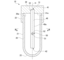
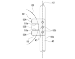
図2は、第1実施形態に係る菌回収システム2で使用する容器10の縦断面図である。図3は、図2に示す矢視III-III断面図である。
これらの図に示すように、容器10は、容器本体20と、蓋体30と、軸体40と、フィルター固定部50と、を備えている。
Fig. 2 is a vertical cross-sectional view of the container 10 used in the bacteria collection system 2 according to the first embodiment. Fig. 3 is a cross-sectional view taken along the line III-III shown in Fig. 2.
As shown in these figures, the container 10 comprises a container body 20, a lid body 30, a shaft body 40, and a filter fixing part 50.

図2に示すように、容器本体20は、有底筒状に形成されている。また、蓋体30は、有頂筒状に形成されている。容器本体20と蓋体30の中心軸Oは、互いに一致している。また、軸体40は、中心軸Oに沿って延びている。以下の説明において、中心軸Oが延びる方向は、軸方向という。また、軸方向から見た平面視において、中心軸Oに交差する方向は、径方向という。また、中心軸O回りに周回する方向は、周方向という。 As shown in FIG. 2, the container body 20 is formed into a cylindrical shape with a bottom. The lid body 30 is formed into a cylindrical shape with a top. The central axes O of the container body 20 and the lid body 30 coincide with each other. The shaft body 40 extends along the central axis O. In the following description, the direction in which the central axis O extends is referred to as the axial direction. In a plan view seen from the axial direction, the direction that intersects with the central axis O is referred to as the radial direction. The direction that rotates around the central axis O is referred to as the circumferential direction.

容器本体20は、上端に開口部20aを有する。容器本体20は、胴部21と、底部22と、を備えている。胴部21は、一定の内径及び外径で軸方向に延びている。底部22は、半球状に形成され、胴部21の下端に連設されている。なお、底部22は、例えば、逆さ円錐状に形成されていても構わない。また、底部22は、当該逆さ円錐状の先端が半球状などの曲面となっていても構わない。また、胴部21は、一定の外径ではなく、下端に向かうに従って内径及び外径が僅かに小さくなる傾斜形状を有しても構わない。 The container body 20 has an opening 20a at the upper end. The container body 20 includes a body 21 and a bottom 22. The body 21 extends in the axial direction with a constant inner and outer diameter. The bottom 22 is formed in a hemispherical shape and is connected to the lower end of the body 21. The bottom 22 may be formed in an inverted cone shape, for example. The tip of the inverted cone may be curved, such as a hemispherical shape. The body 21 may have an inclined shape in which the inner and outer diameters become slightly smaller toward the lower end, rather than a constant outer diameter.

蓋体30は、容器本体20に着脱可能に取り付けられ、開口部20aを封止する。蓋体30は、頂壁31と、周壁32と、を備えている。周壁32は、円筒状に形成され、容器本体20の上端部の外周面に着脱可能に係合している。なお、周壁32の内壁面には、例えば、容器本体20の上端部の外周面に図示しない雄ねじが形成されていた場合、当該雄ねじに螺合する図示しない雌ねじが形成されていてもよい。あるいは、図示とは逆に、蓋体30の周壁32が、容器本体20の開口部20aの内側に入るような構成であっても構わない。また、その場合、容器本体20の上端部の内周面に、図示しない雌ねじが形成され、当該雌ねじに螺合する図示しない雄ねじが、周壁32の外壁面に形成されていても良い。 The lid 30 is detachably attached to the container body 20 and seals the opening 20a. The lid 30 includes a top wall 31 and a peripheral wall 32. The peripheral wall 32 is formed in a cylindrical shape and detachably engages with the outer peripheral surface of the upper end of the container body 20. In addition, when a male screw (not shown) is formed on the outer peripheral surface of the upper end of the container body 20, for example, a female screw (not shown) that screws into the male screw may be formed on the inner wall surface of the peripheral wall 32. Alternatively, the peripheral wall 32 of the lid 30 may be configured to enter the inside of the opening 20a of the container body 20, as opposed to the illustrated configuration. In this case, a female screw (not shown) may be formed on the inner peripheral surface of the upper end of the container body 20, and a male screw (not shown) that screws into the female screw may be formed on the outer wall surface of the peripheral wall 32.

頂壁31は、円板状に形成されると共に周壁32の上端に連設され、周壁32の上端開口を閉塞する。頂壁31の下面31a(蓋体30の内面)には、軸体40が嵌合する嵌合孔33が形成されている。嵌合孔33は、頂壁31の径方向における中心位置に形成されている。なお、蓋体30と軸体40は、別部品が嵌合により組み合わされるものではなく、一体であっても構わない。 The top wall 31 is formed in a disk shape and is connected to the upper end of the peripheral wall 32, closing the upper end opening of the peripheral wall 32. A fitting hole 33 into which the shaft body 40 fits is formed in the lower surface 31a of the top wall 31 (the inner surface of the lid body 30). The fitting hole 33 is formed at the center position in the radial direction of the top wall 31. Note that the lid body 30 and the shaft body 40 do not have to be separate parts that are combined by fitting them together, and may be one piece.

軸体40は、蓋体30に設けられ、容器本体20の内部に向かって直線状に延びている。軸体40の上端部41は、蓋体30の嵌合孔33に嵌合している。一方、軸体40の下端部42は、容器本体20の底部22に接触しないが、底部22の近傍まで延びている。軸体40は、例えば、中実のシャフトである。軸体40は、一定の外径の円柱状に形成されている。あるいは、軸体40は、円柱以外の棒状に形成されていても構わない。 The shaft body 40 is provided on the lid body 30 and extends linearly toward the inside of the container body 20. The upper end 41 of the shaft body 40 fits into the fitting hole 33 of the lid body 30. Meanwhile, the lower end 42 of the shaft body 40 does not contact the bottom 22 of the container body 20, but extends close to the bottom 22. The shaft body 40 is, for example, a solid shaft. The shaft body 40 is formed in a cylindrical shape with a constant outer diameter. Alternatively, the shaft body 40 may be formed in a rod shape other than a cylindrical shape.

フィルター固定部50は、軸体40に設けられている。フィルター固定部50は、軸体40の周囲に後述する捕集フィルター101(図6及び図7参照)を引っ掛けて固定する尖部51を有する。尖部51は、図3に示すように、軸体40の周面40aから突出して設けられている。 The filter fixing part 50 is provided on the shaft body 40. The filter fixing part 50 has a tip 51 that hooks and fixes the collection filter 101 (see Figures 6 and 7) described below around the periphery of the shaft body 40. The tip 51 is provided to protrude from the peripheral surface 40a of the shaft body 40, as shown in Figure 3.

尖部51は、中心軸Oに対し直角に交わる径方向に延びている。尖部51は、径方向外側に向かうに従って先細りになる円錐状に形成されている。なお、尖部51は、先端部だけが尖った針状に形成されていても構わない。また、尖部51は、軸体40が延びる軸方向以外の方向であれば、例えば、中心軸Oに対し鋭角や鈍角で交わる、斜め方向に延びていても構わない。 The tip 51 extends in a radial direction that intersects the central axis O at a right angle. The tip 51 is formed in a cone shape that tapers toward the outside in the radial direction. The tip 51 may be formed in a needle shape that is sharp only at the tip. The tip 51 may also extend in a direction other than the axial direction in which the shaft body 40 extends, for example, in an oblique direction that intersects the central axis O at an acute or obtuse angle.

尖部51は、さらに、尖部51が延びる方向以外の方向に延びる凸部52を有している。凸部52は、円錐状の尖部51の斜面の略中腹部から、尖部51が延びる方向と直交する方向に延びる板状に形成されている。なお、凸部52は、尖部51が延びる方向(径方向)以外の方向であれば、尖部51に対しL字状に屈曲したエルボ形状であってもよいし、釣り針のようなフック形状であっても構わない。図3に示す凸部52は、径方向において一定の厚みを有する板形状である。凸部52は、図2に示すように、尖部51が延びる方向から視て円板状に形成されている。 The tip 51 further has a protrusion 52 extending in a direction other than the direction in which the tip 51 extends. The protrusion 52 is formed in a plate shape extending from approximately the middle of the slope of the conical tip 51 in a direction perpendicular to the direction in which the tip 51 extends. The protrusion 52 may be an elbow shape bent in an L-shape with respect to the tip 51, or a hook shape like a fish hook, as long as it is in a direction other than the direction in which the tip 51 extends (radial direction). The protrusion 52 shown in FIG. 3 is a plate shape having a constant thickness in the radial direction. As shown in FIG. 2, the protrusion 52 is formed in a disk shape when viewed from the direction in which the tip 51 extends.

第1実施形態において、軸体40、尖部51、及び凸部52は、一体成形品であるが、別部品が嵌合などにより組み合わされるものであっても構わない。例えば、凸部52は、尖部51に対し串刺し状に嵌合するリング部材であってもよい。また、尖部51は、軸体40の周面40aに植設された円錐部材、あるいは三角板などの板部材であってもよく、若しくは、三角錐、四面体などの角錐部材であってもよい。 In the first embodiment, the shaft body 40, the tip 51, and the protrusion 52 are integrally molded, but they may be assembled by fitting or other means of separate parts. For example, the protrusion 52 may be a ring member that fits skewer-like into the tip 51. The tip 51 may be a cone member implanted on the peripheral surface 40a of the shaft body 40, or a plate member such as a triangular plate, or a pyramidal member such as a triangular pyramid or tetrahedron.

図3に示すように、軸体40の周面40aには、周方向においてフィルター固定部50と異なる位置に、第2のフィルター固定部60が設けられている。第2のフィルター固定部60は、尖部61及び凸部62を有し、上述したフィルター固定部50と同様の構成となっている。第2のフィルター固定部60は、軸方向から見た平面視において、中心軸Oを中心に、フィルター固定部50と点対称の位置関係を有している。なお、第2のフィルター固定部60は、周方向においてフィルター固定部50と異なる配置であれば、この位置関係に限定されない。 As shown in FIG. 3, a second filter fixing part 60 is provided on the peripheral surface 40a of the shaft body 40 at a different position in the circumferential direction from the filter fixing part 50. The second filter fixing part 60 has a peak 61 and a protrusion 62, and has a similar configuration to the filter fixing part 50 described above. In a plan view seen from the axial direction, the second filter fixing part 60 has a positional relationship that is point-symmetrical with the filter fixing part 50 about the central axis O. Note that the second filter fixing part 60 is not limited to this positional relationship as long as it is disposed in a different position from the filter fixing part 50 in the circumferential direction.

次に、上述した容器10を使用した捕集フィルター101の回収方法及び細胞培養方法について説明する。
図4は、第1実施形態に係るサンプル100の捕集から培養までの工程図である。図5は、第1実施形態に係る菌回収システム2の縦断面図である。図6は、第1実施形態に係る菌回収システム2から捕集フィルター101を回収する様子を示す説明図である。
Next, a method for recovering the collection filter 101 and a method for culturing cells using the above-mentioned container 10 will be described.
Fig. 4 is a process diagram from collection to culture of the sample 100 according to the first embodiment. Fig. 5 is a vertical cross-sectional view of the bacteria collection system 2 according to the first embodiment. Fig. 6 is an explanatory diagram showing the state in which the collection filter 101 is collected from the bacteria collection system 2 according to the first embodiment.

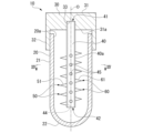
先ず、図5を参照して、菌回収システム2の構成について説明する。図5に示すように、菌回収システム2は、捕集フィルター101を上下で挟み込むフィルター下部70及びフィルター上部80を備えている。捕集フィルター101は、平面視で円形に形成されている。フィルター下部70及びフィルター上部80は、捕集フィルター101の中心を通る中心軸O1を共通軸として、当該中心軸O1が延びる軸方向に、連結部90を介して連結されている。 First, the configuration of the bacteria collection system 2 will be described with reference to FIG. 5. As shown in FIG. 5, the bacteria collection system 2 includes a lower filter portion 70 and an upper filter portion 80 that sandwich the collection filter 101 from above and below. The collection filter 101 is formed in a circular shape in a plan view. The lower filter portion 70 and the upper filter portion 80 are connected via a connecting portion 90 in the axial direction along a central axis O1 that passes through the center of the collection filter 101 as a common axis.

フィルター下部70は、有底筒状の濾過液回収容器71と、濾過液回収容器71の上端開口に装着されたベースプレート72と、を備えている。なお、濾過液回収容器71とベースプレート72は、一体となっていても構わない。濾過液回収容器71の側壁には、吸引ポート71aが設けられている。吸引ポート71aには、減圧吸引チューブ73が接続されている。減圧吸引チューブ73には、図示しない真空ポンプなどの吸引装置本体が接続されている。 The filter lower part 70 includes a cylindrical filtrate collection container 71 with a bottom, and a base plate 72 attached to the upper opening of the filtrate collection container 71. The filtrate collection container 71 and the base plate 72 may be integrated. A suction port 71a is provided on the side wall of the filtrate collection container 71. A reduced pressure suction tube 73 is connected to the suction port 71a. A suction device body such as a vacuum pump (not shown) is connected to the reduced pressure suction tube 73.

ベースプレート72には、濾過液回収容器71の内部に連通する複数の貫通孔72aが形成されている。複数の貫通孔72aの一部には、拡径部72bが形成されている。拡径部72bは、貫通孔72aよりも口径が広くなった溝である。拡径部72bは、上述したフィルター固定部50及び第2のフィルター固定部60の尖部51,61及び凸部52,62が挿入可能な口径及び深さを有している。なお、拡径部72bは、貫通孔72aとは連通しない独立した溝として、ベースプレート72の上面に形成されていても構わない。 The base plate 72 is formed with a plurality of through holes 72a that communicate with the inside of the filtrate collection container 71. Some of the through holes 72a are formed with enlarged diameter sections 72b. The enlarged diameter sections 72b are grooves with a larger diameter than the through holes 72a. The enlarged diameter sections 72b have a diameter and depth that allow the tips 51, 61 and protrusions 52, 62 of the filter fixing part 50 and the second filter fixing part 60 described above to be inserted. The enlarged diameter sections 72b may be formed on the upper surface of the base plate 72 as independent grooves that do not communicate with the through holes 72a.

ベースプレート72の上面には、複数の貫通孔72a及び拡径部72bの周囲を取り囲むフィルター位置決め部72cが形成されている。図5に示すフィルター位置決め部72cは、中心軸O1を中心とする環状に設けられている。また、フィルター位置決め部72cは、捕集フィルター101の外径よりも僅かに大きい内径を有する。 A filter positioning portion 72c is formed on the upper surface of the base plate 72, surrounding the multiple through holes 72a and the enlarged diameter portion 72b. The filter positioning portion 72c shown in FIG. 5 is provided in an annular shape centered on the central axis O1. The filter positioning portion 72c has an inner diameter that is slightly larger than the outer diameter of the collection filter 101.

フィルター位置決め部72cは、ベースプレート72の上面に対し、捕集フィルター101の厚み以上の高さで設けられた環状突起である。なお、フィルター位置決め部72cは、中心軸O1を中心とする周方向に円環として形成されていても良いし、円環として形成されておらず、周方向に間隔をあけて複数設けられた突起群であってもよい。また、フィルター位置決め部72cは、ベースプレート72の上面に対し、相対的に凹んだ溝であっても構わない。 The filter positioning portion 72c is an annular protrusion provided on the upper surface of the base plate 72 at a height equal to or greater than the thickness of the collection filter 101. The filter positioning portion 72c may be formed as a ring in the circumferential direction about the central axis O1, or may not be formed as a ring but may be a group of multiple protrusions provided at intervals in the circumferential direction. The filter positioning portion 72c may also be a groove that is recessed relatively to the upper surface of the base plate 72.

フィルター上部80は、中心軸O1が延びる軸方向に貫通する貫通孔81aが形成されたサポートプレート81と、サポートプレート81に取り付けられ、内部が貫通孔81aに連通する筒状のサンプル注入部82と、を備えている。サポートプレート81の貫通孔81aは、ベースプレート72の複数の貫通孔72aのそれぞれと捕集フィルター101を挟んで対向して配置されている。 The filter upper portion 80 includes a support plate 81 having a through hole 81a formed therein that penetrates in the axial direction along which the central axis O1 extends, and a cylindrical sample injection portion 82 that is attached to the support plate 81 and whose inside communicates with the through hole 81a. The through holes 81a of the support plate 81 are disposed opposite each of the multiple through holes 72a of the base plate 72 with the collection filter 101 in between.

サポートプレート81の下面には、捕集フィルター101の外周縁をベースプレート72の上面に押え付ける封止部が配置されている。封止部は、例えば、サポートプレート81上に設けられた環状の凸部であっても良いし、サポートプレート81より弾性率の低い管状の凸部であっても良い。あるいは、封止部は、本実施形態のように、サポートプレート81の下面の溝部に配設されたOリング83であっても良い。Oリング83は、ベースプレート72のフィルター位置決め部72cの径方向内側に配置されている。Oリング83は、ベースプレート72とサポートプレート81との間に挟まれ、フィルター下部70とフィルター上部80との連結部分からのサンプル100の漏れが無いように隙間をシールする。なお、Oリング83は、サポートプレート81側ではなく、ベースプレート72側に設けられていても構わない。 A sealing portion is disposed on the lower surface of the support plate 81, which presses the outer periphery of the collection filter 101 against the upper surface of the base plate 72. The sealing portion may be, for example, an annular convex portion provided on the support plate 81, or a tubular convex portion having a lower elastic modulus than the support plate 81. Alternatively, the sealing portion may be an O-ring 83 disposed in a groove on the lower surface of the support plate 81, as in this embodiment. The O-ring 83 is disposed radially inside the filter positioning portion 72c of the base plate 72. The O-ring 83 is sandwiched between the base plate 72 and the support plate 81, and seals the gap so that the sample 100 does not leak from the connecting portion between the filter lower portion 70 and the filter upper portion 80. The O-ring 83 may be disposed on the base plate 72 side, not on the support plate 81 side.

サンプル注入部82は、円筒状に形成されている。なお、サンプル注入部82は、ファンネル状(漏斗状)に形成されていても構わない。サンプル注入部82の内部は、サポートプレート81の貫通孔81aに連通している。また、サンプル注入部82は、サポートプレート81と一体となっていてもかなわない。 The sample injection section 82 is formed in a cylindrical shape. The sample injection section 82 may also be formed in a funnel shape. The inside of the sample injection section 82 is connected to the through-hole 81a of the support plate 81. The sample injection section 82 may also be integrated with the support plate 81.

連結部90は、例えば、ベースプレート72及びサポートプレート81のいずれか一方に設けられた図示しない雄ねじ部と、ベースプレート72及びサポートプレート81の他方に設けられた図示しない雌ねじ部と、を含む。この連結部90によれば、ベースプレート72とサポートプレート81とを相対的に回転させることで、フィルター下部70とフィルター上部80とを連結できる。なお、連結部90は、マグネットを有し、ベースプレート72とサポートプレート81とを磁力により連結してもよい。 The connecting portion 90 includes, for example, a male thread portion (not shown) provided on one of the base plate 72 and the support plate 81, and a female thread portion (not shown) provided on the other of the base plate 72 and the support plate 81. With this connecting portion 90, the filter lower portion 70 and the filter upper portion 80 can be connected by rotating the base plate 72 and the support plate 81 relative to each other. The connecting portion 90 may have a magnet and connect the base plate 72 and the support plate 81 by magnetic force.

上記構成の菌回収システム2によるサンプル100のフィルタリング(図4に示すステップS1)は、次のように行う。先ず、サンプル注入部82にサンプル100を入れる。次に、減圧吸引チューブ73によって濾過液回収容器71の内部を減圧する。そうすると、サンプル注入部82に入れられたサンプル100が、濾過液回収容器71の減圧によって、捕集フィルター101を通過し、その液体分が濾過液回収容器71に濾過液102として回収される。その際に、サンプル100中の混濁物(固体分)は、捕集フィルター101の濾過径に応じて捕集フィルター101にトラップ(捕集)される。 Filtering of the sample 100 by the bacteria collection system 2 configured as above (step S1 shown in FIG. 4) is performed as follows. First, the sample 100 is placed in the sample injection section 82. Next, the inside of the filtrate collection container 71 is depressurized by the vacuum suction tube 73. Then, the sample 100 placed in the sample injection section 82 passes through the collection filter 101 due to the depressurization of the filtrate collection container 71, and the liquid content is collected in the filtrate collection container 71 as filtrate 102. At that time, the turbid matter (solid content) in the sample 100 is trapped (collected) by the collection filter 101 according to the filtration diameter of the collection filter 101.

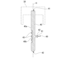
次に、フィルタリング後の捕集フィルター101の回収方法について説明する。先ず、図6(a)に示すように、菌回収システム2のフィルター上部80を取り外した状態とする。なお、この際に、必要に応じて連結部90も取り外すとよい。 Next, a method for recovering the collection filter 101 after filtering will be described. First, as shown in FIG. 6(a), the filter upper part 80 of the bacteria recovery system 2 is removed. At this time, it is advisable to also remove the connecting part 90, if necessary.

次に、上述した図2に示す容器10から蓋体30を取り外すと共に当該蓋体30を把持し、図6(a)に示すように、軸体40に設けられたフィルター固定部50を、捕集フィルター101に押し付け、捕集フィルター101に引っ掛ける(ステップS2)。具体的には、軸体40の尖部51を捕集フィルター101に突き刺すことにより、捕集フィルター101の一端部を軸体40に固定(ホック)する。 Next, the lid 30 is removed from the container 10 shown in FIG. 2 and the lid 30 is grasped, and as shown in FIG. 6(a), the filter fixing portion 50 provided on the shaft 40 is pressed against the collection filter 101 and hooked onto the collection filter 101 (step S2). Specifically, the tip 51 of the shaft 40 is pierced into the collection filter 101, thereby fixing (hooking) one end of the collection filter 101 to the shaft 40.

次に、図6(b)及び図6(c)に示すように、軸体40を回転させ、軸体40に捕集フィルター101を巻き付ける(ステップS3)。具体的には、軸体40をベースプレート72に近接させた状態で回転させながら捕集フィルター101を丸めていく。その後、捕集フィルター101の他端部(尖部51を突き刺した端部と反対側の端部)まで丸めたら、上述した尖部51あるいは、別途設けた尖部61によって捕集フィルター101を突き刺すことにより、捕集フィルター101の他端部を軸体40に固定する。なお、捕集フィルター101のサイズによって、軸体40に対する巻き数は異なるため、適時好適な巻き数にて巻けばよい。 6(b) and 6(c), the shaft body 40 is rotated to wind the collection filter 101 around the shaft body 40 (step S3). Specifically, the collection filter 101 is rolled up while rotating the shaft body 40 in a state where it is close to the base plate 72. After that, when the collection filter 101 is rolled up to the other end (the end opposite the end pierced by the tip 51), the collection filter 101 is pierced by the tip 51 described above or a separately provided tip 61, thereby fixing the other end of the collection filter 101 to the shaft body 40. Note that the number of turns around the shaft body 40 varies depending on the size of the collection filter 101, so it is sufficient to wind it with an appropriate number of turns at the appropriate time.

ここで、尖部51,61には、凸部52,62が設けられているため、突き刺した捕集フィルター101の落下や巻き戻しを抑制できる。また、ベースプレート72には、拡径部72bが設けられているため、尖部51,61及び凸部52,62を含むフィルター固定部50あるいは第2のフィルター固定部60が、捕集フィルター101を貫通し易くなる。また、図6では、尖部61に捕集フィルター101を刺した例を示したが、尖部61に捕集フィルター101を刺す際に拡径部72bが無い場合、尖部61には必ずしも捕集フィルター101を刺さなくても構わない。 Here, the peaks 51, 61 are provided with the convex portions 52, 62, so that the pierced collection filter 101 can be prevented from falling or rewinding. In addition, the base plate 72 is provided with the enlarged diameter portion 72b, so that the filter fixing portion 50 or the second filter fixing portion 60 including the peaks 51, 61 and the convex portions 52, 62 can easily penetrate the collection filter 101. In addition, while FIG. 6 shows an example in which the collection filter 101 is pierced into the peak 61, if there is no enlarged diameter portion 72b when the collection filter 101 is pierced into the peak 61, it is not necessary to pierce the collection filter 101 into the peak 61.

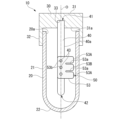
図7は、第1実施形態に係る捕集フィルター101を回収した容器10の縦断面図である。図8は、図7に示す矢視VIII-VIII断面図である。
図7に示す容器10には、培養液103が入れられている。培養液103は、液体培地であって捕集フィルター101が捕集した細菌や真菌を培養するための栄養源となる。なお、培養液103は、捕集フィルター101と容器10とを含む培養キット11に含まれていても良いし、培養キット11と別に用意する構成であっても構わない。
Fig. 7 is a vertical cross-sectional view of the container 10 in which the collection filter 101 according to the first embodiment has been collected. Fig. 8 is a cross-sectional view taken along line VIII-VIII shown in Fig. 7.
7 contains a culture solution 103. The culture solution 103 is a liquid medium and serves as a nutrient source for culturing the bacteria or fungi captured by the collection filter 101. The culture solution 103 may be included in a culture kit 11 including the collection filter 101 and the container 10, or may be prepared separately from the culture kit 11.

上述したように捕集フィルター101を回収したら、容器本体20に培養液103(液体培地)を添加する(ステップS4)。次に、培養液103を入れた状態の容器本体20に、捕集フィルター101が巻き付いた軸体40を挿入し、蓋体30で開口部20aを封止する(ステップS5)。そして、捕集フィルター101を収容した図7に示す容器10を振盪培養器にかけ、捕集した細菌や真菌を振盪培養する(ステップS6)。あるいは一定温度に保たれた培養器に入れ、静置培養を行っても良い。以上により、菌回収システム2におけるサンプル100のフィルタリング、及び捕集フィルター101の回収から細胞培養までが終了する。 After the collection filter 101 is collected as described above, the culture solution 103 (liquid medium) is added to the container body 20 (step S4). Next, the shaft body 40 with the collection filter 101 wound around it is inserted into the container body 20 containing the culture solution 103, and the opening 20a is sealed with the lid body 30 (step S5). Then, the container 10 shown in FIG. 7 containing the collection filter 101 is placed in a shaking incubator, and the collected bacteria and fungi are shake-cultured (step S6). Alternatively, they may be placed in an incubator kept at a constant temperature and subjected to static culture. This completes the process from filtering the sample 100 and collecting the collection filter 101 to cell culture in the bacteria collection system 2.

上述したように、第1実施形態の容器10によれば、軸体40にフィルター固定部50を設けられているため、細胞が付着した捕集フィルター101を軸体40に引っ掛け、軸体40に巻き付けて回収することができる。このように、作業者は、簡単な操作で捕集フィルター101を回収することができる。そこで、捕集フィルター101を培養のための容器10に入れる際に、誤って捕集フィルター101を培養のための容器10以外の作業者が意図しない部位に触れさせてしまい、捕集フィルター101に、意図しない部位に付着した菌などを付着させてしまうコンタミネーションの発生を抑制することができる。また、フィルター固定部50があることで、作業者のスキルに左右されずに、捕集フィルター101の落下を抑制できる。また、軸体40を容器本体20に挿入したままで、振盪培養することが可能となり、振盪培養中に培養液が容器本体20からこぼれるリスクや、外部から意図しない菌などが混入するコンタミネーションのリスクが低くなる。 As described above, according to the container 10 of the first embodiment, since the filter fixing part 50 is provided on the shaft body 40, the collection filter 101 to which the cells are attached can be hooked on the shaft body 40 and wound around the shaft body 40 for collection. In this way, the operator can collect the collection filter 101 with a simple operation. Therefore, when placing the collection filter 101 in the container 10 for culture, the operator other than the container 10 for culture may accidentally touch the collection filter 101 to an unintended part, and the collection filter 101 may be contaminated with bacteria attached to the unintended part. In addition, the presence of the filter fixing part 50 makes it possible to prevent the collection filter 101 from falling off regardless of the skill of the operator. In addition, it is possible to perform shaking culture with the shaft body 40 inserted in the container body 20, which reduces the risk of the culture medium spilling from the container body 20 during shaking culture and the risk of contamination due to the introduction of unintended bacteria from the outside.

このように、上述した第1実施形態の容器10は、開口部20aを有する容器本体20と、容器本体20に着脱可能に取り付けられ、開口部20aを封止する蓋体30と、蓋体30に設けられ、容器本体20の内部に向かって延びる軸体40と、軸体40に設けられ、捕集フィルター101を引っ掛けて軸体40に固定するフィルター固定部50と、を備える。この構成によれば、作業者のスキルに左右されず、コンタミネーションのリスクや操作ミスを抑制することができる。 As described above, the container 10 of the first embodiment includes a container body 20 having an opening 20a, a lid body 30 that is detachably attached to the container body 20 and seals the opening 20a, a shaft body 40 that is provided on the lid body 30 and extends toward the inside of the container body 20, and a filter fixing part 50 that is provided on the shaft body 40 and hooks the collection filter 101 to fix it to the shaft body 40. This configuration makes it possible to reduce the risk of contamination and operational errors regardless of the skill of the operator.

また、本実施形態では、フィルター固定部50は、軸体40が延びる軸方向以外の方向に延びる尖部51を有する。この構成によれば、軸体40の尖部51を捕集フィルター101に突き刺すことにより、捕集フィルター101を容易に固定(ホック)できる。 In addition, in this embodiment, the filter fixing portion 50 has a tip 51 that extends in a direction other than the axial direction along which the shaft body 40 extends. With this configuration, the collection filter 101 can be easily fixed (hooked) by piercing the tip 51 of the shaft body 40 into the collection filter 101.

また、本実施形態では、軸体40の周方向においてフィルター固定部50と異なる位置に設けられた第2のフィルター固定部60を備える。この構成によれば、捕集フィルター101の巻き始めと巻き終えの位置に、フィルター固定部50が位置していなくても、第2のフィルター固定部60によって捕集フィルター101を突き刺し、捕集フィルター101の巻き戻しを抑制できる。 In addition, in this embodiment, a second filter fixing part 60 is provided at a different position from the filter fixing part 50 in the circumferential direction of the shaft body 40. With this configuration, even if the filter fixing part 50 is not located at the start and end positions of the collection filter 101, the second filter fixing part 60 can pierce the collection filter 101 and prevent the collection filter 101 from rewinding.

また、本実施形態では、第2のフィルター固定部60は、軸体40が延びる軸方向以外の方向に延びる尖部61を有する。この構成によれば、軸体40の尖部61を捕集フィルター101に突き刺すことにより、捕集フィルター101の巻き戻しをより確実に抑制できる。 In addition, in this embodiment, the second filter fixing portion 60 has a tip 61 that extends in a direction other than the axial direction in which the shaft body 40 extends. With this configuration, by piercing the tip 61 of the shaft body 40 into the collection filter 101, it is possible to more reliably suppress the rewinding of the collection filter 101.

また、本実施形態では、尖部51,61は、尖部51,61が延びる方向以外の方向に延びる凸部52,62を有する。この構成によれば、尖部51,61に突き刺された捕集フィルター101が凸部52,62に引っ掛かるため、捕集フィルター101の落下のリスクが低くなる。また、図8に示すように、例えば凸部62が、捕集フィルター101の巻きによる重なる部分に隙間を形成するスペーサ的な役割を果たすことで、巻き取られた捕集フィルター101の隙間にも培養液103の流れを形成できるようになり、細胞培養を効果的に行えるようになる。
このような目的に鑑み、前述の例では凸部52,62は、それぞれ尖部51,61に1つ形成された例を示したが、凸部52,62はそれぞれに1つである必要は無く、尖部51,61に複数の凸部52,62を形成する構成としても良い。
Furthermore, in this embodiment, the apex 51, 61 has a protrusion 52, 62 that extends in a direction other than the direction in which the apex 51, 61 extends. With this configuration, the collection filter 101 pierced by the apex 51, 61 is caught by the protrusion 52, 62, reducing the risk of the collection filter 101 falling. Also, as shown in Fig. 8, for example, the protrusion 62 acts as a spacer that forms a gap in the overlapping portion caused by the rolled up collection filter 101, so that a flow of the culture solution 103 can be formed in the gap in the rolled up collection filter 101, making it possible to effectively carry out cell culture.
In consideration of this purpose, in the above example, one convex portion 52, 62 is formed on each of the peaks 51, 61, but it is not necessary that there is only one convex portion 52, 62 on each of the peaks 51, 61, and it is also possible to form multiple convex portions 52, 62 on each of the peaks 51, 61.

また、本実施形態の培養キット11は、細胞を捕集する捕集フィルター101と、捕集フィルター101及び培養液103が封入される容器10と、を備える。この構成によれば、容器10に捕集フィルター101を収容し、細胞培養が可能となる。 The culture kit 11 of this embodiment also includes a collection filter 101 for collecting cells, and a container 10 in which the collection filter 101 and culture solution 103 are sealed. With this configuration, the collection filter 101 is housed in the container 10, making it possible to culture cells.

また、本実施形態の核酸分析システム1は、上記容器10を用いて細胞を捕集し、該容器10に培養液を封入し培養した細胞、若しくは、上記培養キット11を用いて捕集及び培養した細胞から核酸を抽出し、該抽出した核酸を分析する。この構成によれば、コンタミネーションのリスクが低くなっているため、核酸の分析精度が向上する。 The nucleic acid analysis system 1 of this embodiment collects cells using the container 10, encloses a culture medium in the container 10 and cultures the cells, or extracts nucleic acids from cells collected and cultured using the culture kit 11, and analyzes the extracted nucleic acids. This configuration reduces the risk of contamination, improving the accuracy of nucleic acid analysis.

また、本実施形態の捕集フィルター回収方法は、細胞が付着した捕集フィルター101を、軸体40に引っ掛け、軸体40に巻き付けて回収する。この構成によれば、作業者のスキルに左右されず、コンタミネーションのリスクや操作ミスを抑制することができる。 In addition, the collection filter recovery method of this embodiment involves hooking the collection filter 101 with cells attached to the shaft body 40 and winding it around the shaft body 40 to recover it. This configuration makes it possible to reduce the risk of contamination and operational errors without being dependent on the skill of the operator.

また、本実施形態の細胞培養方法は、細胞が付着した捕集フィルター101を、軸体40に引っ掛け、軸体40に巻き付けて回収し、捕集フィルター101が巻き付いた軸体40を培養液103に漬け、細胞を振盪培養する。作業者のスキルに左右されず、コンタミネーションのリスクや操作ミスを抑制することができる。また、捕集フィルター101に付着した細胞の効率的な振盪培養が可能となる。 In addition, in the cell culture method of this embodiment, the collection filter 101 with cells attached thereto is hooked onto the shaft body 40, wound around the shaft body 40 and collected, and the shaft body 40 with the collection filter 101 wound around it is immersed in the culture solution 103 and the cells are cultured by shaking. This is not dependent on the skill of the operator, and it is possible to reduce the risk of contamination and operational errors. In addition, it is possible to efficiently culture the cells attached to the collection filter 101 by shaking.

〔第2実施形態〕
次に、本発明の第2実施形態について説明する。以下の説明において、上述の実施形態と同一又は同等の構成については同一の符号を付し、その説明を簡略若しくは省略する。
Second Embodiment
Next, a second embodiment of the present invention will be described. In the following description, the same or equivalent components as those in the above-described embodiment are denoted by the same reference numerals, and the description thereof will be simplified or omitted.

図9は、第2実施形態に係る容器10の縦断面図である。図10は、第2実施形態に係る軸体40の縦断面図である。
図9に示すように、第2実施形態のフィルター固定部50は、スリット53aが形成されたスリット片53を有している。
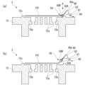
Fig. 9 is a vertical cross-sectional view of the container 10 according to the second embodiment. Fig. 10 is a vertical cross-sectional view of the shaft body 40 according to the second embodiment.
As shown in FIG. 9, a filter fixing portion 50 of the second embodiment has a slit piece 53 in which a slit 53a is formed.

スリット片53は、例えば、弾性変形可能なフィルム部材であって、軸体40の周面40aに取り付けられている。軸体40の周面40aには、図10に示すように、スリット片53の径方向の厚みに応じた深さを有する取付溝40bが形成されている。取付溝40bには、底面から径方向に立ち上がった複数の圧入ピン43が、軸方向に間隔をあけて複数形成されている。圧入ピン43は、図9に示すように、スリット片53に設けられた取付孔53bに圧入され、スリット片53を軸体40に固定する。 The slit piece 53 is, for example, an elastically deformable film member, and is attached to the peripheral surface 40a of the shaft body 40. As shown in FIG. 10, a mounting groove 40b is formed on the peripheral surface 40a of the shaft body 40, with a depth corresponding to the radial thickness of the slit piece 53. The mounting groove 40b has a plurality of press-fit pins 43 that rise radially from the bottom surface and are formed at intervals in the axial direction. As shown in FIG. 9, the press-fit pins 43 are press-fitted into mounting holes 53b provided in the slit piece 53, and fix the slit piece 53 to the shaft body 40.

スリット片53は、軸体40から周面40aの接線方向に沿って延びている。スリット片53の接線方向に延びた先端部には、軸方向に間隔をあけて複数のスリット53aが形成されている。複数のスリット53aは、スリット片53の先端部からスリット片53の固定位置に向かって平行に延びている。第2実施形態のスリット53aは、2本平行に形成され、スリット片53の先端部を弾性変形可能な3つの舌部に分離している。以下、2本のスリット53aの軸方向外側に配置された一対の舌部を、第1の舌部53Aという。また、2本のスリット53aに挟まれた舌部を、第2の舌部53Bという。 The slit piece 53 extends from the shaft 40 along the tangential direction of the circumferential surface 40a. A plurality of slits 53a are formed at the tip of the slit piece 53 extending in the tangential direction, spaced apart in the axial direction. The plurality of slits 53a extend in parallel from the tip of the slit piece 53 toward the fixed position of the slit piece 53. In the second embodiment, two slits 53a are formed in parallel, and the tip of the slit piece 53 is separated into three elastically deformable tongue portions. Hereinafter, the pair of tongue portions arranged axially outside the two slits 53a will be referred to as the first tongue portion 53A. The tongue portion sandwiched between the two slits 53a will be referred to as the second tongue portion 53B.

図11は、第2実施形態に係る菌回収システム2から捕集フィルター101を回収する様子を示す説明図である。図12は、図11(a)に示す矢視A図である。
図11(a)及び図12に示すように、第2実施形態では、スリット片53のスリット53aに、捕集フィルター101の端部を引っ掛けて、捕集フィルター101を回収する。
Fig. 11 is an explanatory diagram showing how the collection filter 101 is collected from the bacteria collection system 2 according to the second embodiment. Fig. 12 is a view taken along the arrow A in Fig. 11(a).
As shown in FIGS. 11A and 12, in the second embodiment, the collection filter 101 is collected by hooking an end of the collection filter 101 onto a slit 53 a of a slit piece 53 .

具体的には、図12に示すように、スリット片53の2本のスリット53aに捕集フィルター101の端部を差し込む。そして、2本のスリット53aで分離した第1の舌部53Aと第2の舌部53Bとで、捕集フィルター101の端部を挟み込む。なお、第2の舌部53Bを捕集フィルター101の下に差し込み易くするために、第2の舌部53Bの長さを第1の舌部53Aよりも長くしてもよい。また、第2の舌部53Bを捕集フィルター101の下に差し込み易くするために、第1の舌部53Aは予め上向きに曲がって(例えばカールして)いてもよい。 Specifically, as shown in FIG. 12, the end of the collection filter 101 is inserted into the two slits 53a of the slit piece 53. Then, the end of the collection filter 101 is sandwiched between the first tongue portion 53A and the second tongue portion 53B separated by the two slits 53a. Note that the length of the second tongue portion 53B may be longer than the first tongue portion 53A to make it easier to insert the second tongue portion 53B under the collection filter 101. Also, the first tongue portion 53A may be bent upward (e.g., curled) in advance to make it easier to insert the second tongue portion 53B under the collection filter 101.

次に、図11(b)に示すように、軸体40に固定(ホック)した捕集フィルター101を持ち上げて、上述した第1実施形態と同様に、軸体40を回転させ、軸体40に捕集フィルター101を巻き付ける。その後、捕集フィルター101の他端部(スリット53aに差し込んだ端部と反対側の端部)まで丸めたら、上述した尖部61によって捕集フィルター101を突き刺すことにより、捕集フィルター101の他端部を軸体40に固定する。 11(b), the collection filter 101 fixed (hooked) to the shaft body 40 is lifted, and the shaft body 40 is rotated as in the first embodiment described above, and the collection filter 101 is wound around the shaft body 40. After that, the collection filter 101 is rolled up to the other end (the end opposite the end inserted into the slit 53a), and the collection filter 101 is pierced with the pointed portion 61 described above, thereby fixing the other end of the collection filter 101 to the shaft body 40.

このように第2実施形態のフィルター固定部50は、スリット53aが形成されたスリット片53を有する。この構成によれば、スリット53aに捕集フィルター101の端部を挟んで固定することにより、上述した第1実施形態と同様に捕集フィルター101を丸めながら回収することが可能となる。よって、上述した第1実施形態に記載した同様の効果を得ることができる。 In this way, the filter fixing part 50 of the second embodiment has a slit piece 53 in which a slit 53a is formed. With this configuration, by clamping and fixing the end of the collection filter 101 in the slit 53a, it becomes possible to collect the collection filter 101 while rolling it up, as in the first embodiment described above. Therefore, it is possible to obtain the same effects as those described in the first embodiment described above.

〔第3実施形態〕
次に、本発明の第3実施形態について説明する。以下の説明において、上述の実施形態と同一又は同等の構成については同一の符号を付し、その説明を簡略若しくは省略する。
Third Embodiment
Next, a third embodiment of the present invention will be described. In the following description, the same or equivalent components as those in the above-described embodiment are denoted by the same reference numerals, and the description thereof will be simplified or omitted.

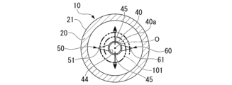
図13は、第3実施形態に係る容器10の縦断面図である。図14は、図13に示す矢視XIV-XIV断面図である。
図13に示すように、第3実施形態では、フィルター固定部50及び第2のフィルター固定部60が、軸体40の周面40aに軸方向に間隔をあけて複数形成されている。なお、図13,14に図示した第3実施形態の尖部51,61は、上述した凸部52,62を有していないが、上述した凸部52,62を有していても構わない。
Fig. 13 is a vertical cross-sectional view of the container 10 according to the third embodiment. Fig. 14 is a cross-sectional view taken along line XIV-XIV shown in Fig. 13.
As shown in Fig. 13, in the third embodiment, a plurality of filter fixing portions 50 and second filter fixing portions 60 are formed at intervals in the axial direction on the peripheral surface 40a of the shaft body 40. Note that the pointed portions 51, 61 of the third embodiment shown in Figs. 13 and 14 do not have the above-mentioned convex portions 52, 62, but may have the above-mentioned convex portions 52, 62.

また、第3実施形態の軸体40は、中空軸である。軸体40には、上端部41から下端部42まで貫通する中空空間44が形成されている。また、軸体40の周面40aには、複数の貫通孔45が形成されている。貫通孔45は、軸体40の中空空間44と連通している。貫通孔45は、軸体40の軸方向に間隔をあけて複数形成されている。また、貫通孔45は、図14に示すように、軸体40の周方向において異なる二カ所に形成されている。 The shaft body 40 of the third embodiment is a hollow shaft. A hollow space 44 is formed in the shaft body 40, penetrating from the upper end 41 to the lower end 42. A plurality of through holes 45 are formed in the peripheral surface 40a of the shaft body 40. The through holes 45 are connected to the hollow space 44 of the shaft body 40. The through holes 45 are formed at intervals in the axial direction of the shaft body 40. The through holes 45 are formed at two different locations in the circumferential direction of the shaft body 40, as shown in FIG. 14.

上記構成の第3実施形態によれば、軸体40の下端部42から中空空間44に入った培養液103を、軸体40の貫通孔45から流出させることができる。これにより、軸体40に巻き付けた捕集フィルター101に対して径方向内側からも培養液103を供給でき、捕集フィルター101に付着した細胞の効率的な振盪培養が可能となる。 According to the third embodiment having the above configuration, the culture fluid 103 that has entered the hollow space 44 from the lower end 42 of the shaft body 40 can be made to flow out from the through-hole 45 of the shaft body 40. This allows the culture fluid 103 to be supplied from the radial inside to the collection filter 101 wrapped around the shaft body 40, enabling efficient shaking culture of the cells attached to the collection filter 101.

以上、図面を参照しながら本発明の好適な実施形態について説明したが、本発明は上記実施形態に限定されるものではない。上述した実施形態において示した各構成部材の諸形状や組み合わせ等は一例であって、本発明の主旨から逸脱しない範囲において設計要求等に基づき種々変更可能である。 Although the preferred embodiment of the present invention has been described above with reference to the drawings, the present invention is not limited to the above embodiment. The shapes and combinations of the components shown in the above embodiment are merely examples, and various modifications can be made based on design requirements, etc., without departing from the spirit of the present invention.

例えば、図15及び図16に示すような変形例を採用してもよい。 For example, modified examples such as those shown in Figures 15 and 16 may be adopted.

図15は、第1実施形態の一変形例に係る容器10の横断面図である。
図15に示すように、尖部51,61は、軸体40の中心軸Oに対し直角に交わる径方向ではない斜め方向(例えば、軸体40の接線方向)に伸びていても構わない。
FIG. 15 is a cross-sectional view of the container 10 according to a modified example of the first embodiment.
As shown in FIG. 15, the tips 51, 61 may extend in an oblique direction (for example, a tangential direction of the shaft body 40) other than a radial direction perpendicular to the central axis O of the shaft body 40.

図16は、第1実施形態の一変形例に係る容器10の横断面図である。
図16に示すように、尖部51,61は、軸体40の中心軸Oに対し直角に交わる径方向に直線状に延びておらず、軸体40の周方向に湾曲して伸びていても構わない。
FIG. 16 is a cross-sectional view of the container 10 according to a modified example of the first embodiment.
As shown in FIG. 16 , the tips 51 , 61 do not necessarily extend linearly in the radial direction perpendicular to the central axis O of the shaft body 40 , but may extend curvedly in the circumferential direction of the shaft body 40 .

1 核酸分析システム
10 容器
11 培養キット
20 容器本体
20a 開口部
30 蓋体
40 軸体
50 フィルター固定部
51 尖部
52 凸部
61 尖部
62 凸部
100 サンプル
101 捕集フィルター(フィルター)
103 培養液
1 Nucleic acid analysis system 10 Container 11 Culture kit 20 Container body 20a Opening 30 Lid 40 Shaft 50 Filter fixing part 51 Tip 52 Convex part 61 Tip 62 Convex part 100 Sample 101 Collection filter (filter)
103 Culture medium

Claims (10)

開口部を有する容器本体と、
前記容器本体に着脱可能に取り付けられ、前記開口部を封止する蓋体と、
前記蓋体に設けられ、前記容器本体の内部に向かって延びる軸体と、
前記軸体の周面に設けられ、前記軸体に巻き付け固定されるフィルターを引っ掛ける引っ掛け部を有するフィルター固定部と、を備える、容器。
A container body having an opening;
a cover body that is detachably attached to the container body and seals the opening;
A shaft body provided on the lid body and extending toward the inside of the container body;
a filter fixing portion provided on the peripheral surface of the shaft body and having a hook portion for hooking a filter that is wound around and fixed to the shaft body .
前記引っ掛け部は、前記軸体が延びる軸方向以外の方向に延びる尖部である、請求項1に記載の容器。 The container according to claim 1 , wherein the hook portion is a pointed portion extending in a direction other than the axial direction along which the shaft body extends. 前記引っ掛け部は、スリットが形成されたスリット片である、請求項1に記載の容器。 The container according to claim 1 , wherein the hook portion is a slit piece having a slit formed therein. 前記軸体の周方向において前記フィルター固定部と異なる位置に設けられた第2のフィルター固定部を備える、請求項1~3のいずれか一項に記載の容器。 The container according to any one of claims 1 to 3, comprising a second filter fixing part provided at a different position from the filter fixing part in the circumferential direction of the shaft. 前記第2のフィルター固定部は、前記軸体が延びる軸方向以外の方向に延びる尖部を有する、請求項4に記載の容器。 The container according to claim 4, wherein the second filter fixing portion has a tip that extends in a direction other than the axial direction along which the shaft body extends. 前記尖部は、前記尖部が延びる方向以外の方向に延びる凸部を有する、請求項2または5に記載の容器。 The container according to claim 2 or 5, wherein the pointed portion has a protrusion extending in a direction other than the direction in which the pointed portion extends. 細胞を捕集するフィルターと、
前記フィルター及び培養液が封入される請求項1~6のいずれか一項に記載の容器と、
を備える、培養キット。
A filter for collecting cells;
A container according to any one of claims 1 to 6 in which the filter and the culture solution are enclosed;
A culture kit comprising:
請求項1~6のいずれか一項に記載の容器を用いて細胞を捕集し、該容器に培養液を封入して培養した細胞から核酸を抽出し、該抽出した核酸を分析する、核酸分析システム。 A nucleic acid analysis system that collects cells using a container according to any one of claims 1 to 6, encloses a culture medium in the container, extracts nucleic acid from the cultured cells, and analyzes the extracted nucleic acid. 請求項7に記載の培養キットを用いて捕集及び培養した細胞から核酸を抽出し、該抽出した核酸を分析する、核酸分析システム。 A nucleic acid analysis system that extracts nucleic acid from cells collected and cultured using the culture kit according to claim 7, and analyzes the extracted nucleic acid. 請求項1~6のいずれか一項に記載の容器から取り外された前記蓋体に設けられた前記軸体の前記引っ掛け部に前記フィルターを引っ掛け、前記軸体を回転させて前記フィルターを前記軸体に巻き付け固定し、The filter is hooked to the hook portion of the shaft provided on the lid body removed from the container according to any one of claims 1 to 6, and the shaft body is rotated to wind and fix the filter around the shaft body;
培養液が添加された前記容器本体に、前記フィルターが巻き付け固定された前記軸体を挿入して前記蓋体で前記容器本体の前記開口部を封止して前記フィルターに捕集された細胞を培養する、the shaft body around which the filter is wound and fixed is inserted into the container body to which a culture medium has been added, and the opening of the container body is sealed with the lid body to culture the cells captured on the filter.
細胞培養方法。Cell culture methods.
JP2021001678A 2021-01-07 2021-01-07 Container, culture kit, nucleic acid analysis system, and cell culture method Active JP7635554B2 (en)

Priority Applications (1)

Application Number Priority Date Filing Date Title
JP2021001678A JP7635554B2 (en) 2021-01-07 2021-01-07 Container, culture kit, nucleic acid analysis system, and cell culture method

Applications Claiming Priority (1)

Application Number Priority Date Filing Date Title
JP2021001678A JP7635554B2 (en) 2021-01-07 2021-01-07 Container, culture kit, nucleic acid analysis system, and cell culture method

Publications (2)

Publication Number Publication Date
JP2022106580A JP2022106580A (en) 2022-07-20
JP7635554B2 true JP7635554B2 (en) 2025-02-26

Family

ID=82457107

Family Applications (1)

Application Number Title Priority Date Filing Date
JP2021001678A Active JP7635554B2 (en) 2021-01-07 2021-01-07 Container, culture kit, nucleic acid analysis system, and cell culture method

Country Status (1)

Country Link
JP (1) JP7635554B2 (en)

Families Citing this family (2)

* Cited by examiner, † Cited by third party
Publication number Priority date Publication date Assignee Title
JP2024067730A (en) * 2022-11-07 2024-05-17 横河電機株式会社 Culture vessel, microbial culture system, and nucleic acid analysis system
JP2025100032A (en) * 2023-12-22 2025-07-03 横河電機株式会社 Filter suction holder, nucleic acid extraction system, and nucleic acid extraction method

Citations (4)

* Cited by examiner, † Cited by third party
Publication number Priority date Publication date Assignee Title
US20100028933A1 (en) 2007-03-21 2010-02-04 Sartorius Stedim Biotech Gmbh Nutrient medium unit and method for holding a filter from a filtration device
JP2013198442A (en) 2012-03-26 2013-10-03 Terumo Corp Transfer device
WO2019043779A1 (en) 2017-08-29 2019-03-07 横河電機株式会社 Nucleic acid extraction method and nucleic acid extraction device
WO2020009099A1 (en) 2018-07-03 2020-01-09 株式会社村田製作所 Filtration recovery device and filtration recovery method

Family Cites Families (3)

* Cited by examiner, † Cited by third party
Publication number Priority date Publication date Assignee Title
CA2226857C (en) * 1995-07-12 2008-03-18 Charm Sciences, Inc. Test apparatus, system and method for the detection of test samples
JPH10257887A (en) * 1996-09-30 1998-09-29 Dainippon Printing Co Ltd Gene analysis apparatus and method
JP3431812B2 (en) * 1996-11-07 2003-07-28 株式会社エスアールエル Bacteria detection instrument

Patent Citations (4)

* Cited by examiner, † Cited by third party
Publication number Priority date Publication date Assignee Title
US20100028933A1 (en) 2007-03-21 2010-02-04 Sartorius Stedim Biotech Gmbh Nutrient medium unit and method for holding a filter from a filtration device
JP2013198442A (en) 2012-03-26 2013-10-03 Terumo Corp Transfer device
WO2019043779A1 (en) 2017-08-29 2019-03-07 横河電機株式会社 Nucleic acid extraction method and nucleic acid extraction device
WO2020009099A1 (en) 2018-07-03 2020-01-09 株式会社村田製作所 Filtration recovery device and filtration recovery method

Also Published As

Publication number Publication date
JP2022106580A (en) 2022-07-20

Similar Documents

Publication Publication Date Title
US12091703B2 (en) Cell culturing device
US20230416663A1 (en) Cassette for sterility testing
JP7635554B2 (en) Container, culture kit, nucleic acid analysis system, and cell culture method
US4829005A (en) Sedimentation filtration microorganism growth culture system
US2879207A (en) Filtration and incubation unit
JP3130132B2 (en) Method and apparatus for microbiological testing of pressurized liquids
JP6572219B2 (en) Sample preparation unit and sample preparation device
CN111286449B (en) Biological sample pretreatment reagent integrated adding method and device
CN111065446B (en) Filter assembly and method for microbiological testing
CN103298546A (en) Method and system for cell filtration
EP3678760B1 (en) Filtration assembly and method for microbiological testing
KR20120090785A (en) Peristaltic pumps and filtration assembly systems for use therewith
US20160017274A1 (en) Device and method for treating a filtration medium
CN102816683B (en) Biochemical culture and detection device as well as detection method thereof
CN104662144A (en) Disposable container for bioburden sample collection and detection
JP2009118780A (en) Microorganism detection method and filtration apparatus
TWI802111B (en) Cell activation reactor and cell activation method
CN211227137U (en) Sample treatment and filtration device for detecting microorganisms in clinical samples
WO1990013624A1 (en) Microorganism growth culture system, method and filtration unit utilized therewith
JP2004236547A (en) Cell culture disk and cell culture apparatus using the same
CN113181772A (en) Bacteria collection device and method
CN113677434B (en) Device for determining the presence of bacterial contamination in a fluid
US20250205709A1 (en) Filter suction holder, nucleic acid extraction system, and nucleic acid extraction method
US20250082806A1 (en) Sterility testing drain actuator base
EP4633806A1 (en) Device and method for sample concentration

Legal Events

Date Code Title Description
A621 Written request for application examination

Free format text: JAPANESE INTERMEDIATE CODE: A621

Effective date: 20231116

A977 Report on retrieval

Free format text: JAPANESE INTERMEDIATE CODE: A971007

Effective date: 20240830

A131 Notification of reasons for refusal

Free format text: JAPANESE INTERMEDIATE CODE: A131

Effective date: 20240903

A521 Request for written amendment filed

Free format text: JAPANESE INTERMEDIATE CODE: A523

Effective date: 20241031

TRDD Decision of grant or rejection written
A01 Written decision to grant a patent or to grant a registration (utility model)

Free format text: JAPANESE INTERMEDIATE CODE: A01

Effective date: 20250114

A61 First payment of annual fees (during grant procedure)

Free format text: JAPANESE INTERMEDIATE CODE: A61

Effective date: 20250127

R150 Certificate of patent or registration of utility model

Ref document number: 7635554

Country of ref document: JP

Free format text: JAPANESE INTERMEDIATE CODE: R150