JP7635472B1 - Sealed structure - Google Patents
Sealed structure Download PDFInfo
- Publication number
- JP7635472B1 JP7635472B1 JP2024573754A JP2024573754A JP7635472B1 JP 7635472 B1 JP7635472 B1 JP 7635472B1 JP 2024573754 A JP2024573754 A JP 2024573754A JP 2024573754 A JP2024573754 A JP 2024573754A JP 7635472 B1 JP7635472 B1 JP 7635472B1
- Authority
- JP
- Japan
- Prior art keywords
- gasket
- mounting groove
- side wall
- protrusions
- sealing structure
- Prior art date
- Legal status (The legal status is an assumption and is not a legal conclusion. Google has not performed a legal analysis and makes no representation as to the accuracy of the status listed.)
- Active
Links
Images


Classifications
-
- F—MECHANICAL ENGINEERING; LIGHTING; HEATING; WEAPONS; BLASTING
- F16—ENGINEERING ELEMENTS AND UNITS; GENERAL MEASURES FOR PRODUCING AND MAINTAINING EFFECTIVE FUNCTIONING OF MACHINES OR INSTALLATIONS; THERMAL INSULATION IN GENERAL
- F16J—PISTONS; CYLINDERS; SEALINGS
- F16J15/00—Sealings
- F16J15/02—Sealings between relatively-stationary surfaces
- F16J15/06—Sealings between relatively-stationary surfaces with solid packing compressed between sealing surfaces
- F16J15/061—Sealings between relatively-stationary surfaces with solid packing compressed between sealing surfaces with positioning means
-
- F—MECHANICAL ENGINEERING; LIGHTING; HEATING; WEAPONS; BLASTING
- F16—ENGINEERING ELEMENTS AND UNITS; GENERAL MEASURES FOR PRODUCING AND MAINTAINING EFFECTIVE FUNCTIONING OF MACHINES OR INSTALLATIONS; THERMAL INSULATION IN GENERAL
- F16J—PISTONS; CYLINDERS; SEALINGS
- F16J15/00—Sealings
- F16J15/02—Sealings between relatively-stationary surfaces
- F16J15/021—Sealings between relatively-stationary surfaces with elastic packing
- F16J15/022—Sealings between relatively-stationary surfaces with elastic packing characterised by structure or material
- F16J15/024—Sealings between relatively-stationary surfaces with elastic packing characterised by structure or material the packing being locally weakened in order to increase elasticity
- F16J15/027—Sealings between relatively-stationary surfaces with elastic packing characterised by structure or material the packing being locally weakened in order to increase elasticity and with a hollow profile
-
- F—MECHANICAL ENGINEERING; LIGHTING; HEATING; WEAPONS; BLASTING
- F16—ENGINEERING ELEMENTS AND UNITS; GENERAL MEASURES FOR PRODUCING AND MAINTAINING EFFECTIVE FUNCTIONING OF MACHINES OR INSTALLATIONS; THERMAL INSULATION IN GENERAL
- F16J—PISTONS; CYLINDERS; SEALINGS
- F16J15/00—Sealings
- F16J15/02—Sealings between relatively-stationary surfaces
- F16J15/06—Sealings between relatively-stationary surfaces with solid packing compressed between sealing surfaces
- F16J15/10—Sealings between relatively-stationary surfaces with solid packing compressed between sealing surfaces with non-metallic packing
- F16J15/104—Sealings between relatively-stationary surfaces with solid packing compressed between sealing surfaces with non-metallic packing characterised by structure
- F16J15/106—Sealings between relatively-stationary surfaces with solid packing compressed between sealing surfaces with non-metallic packing characterised by structure homogeneous
Landscapes
- Engineering & Computer Science (AREA)
- General Engineering & Computer Science (AREA)
- Mechanical Engineering (AREA)
- Gasket Seals (AREA)
Abstract
装着溝にガスケットを装着した際に、ガスケットの一部が装着溝から浮き上がってしまうことを抑制可能な密封構造を提供する。
ガスケット300は、装着溝210に装着される環状のガスケット本体部310と、ガスケット本体部310の内周面に、周方向に間隔を空けて複数設けられる突起320と、を備えると共に、ガスケット300が装着溝210に装着され、かつ、第1部材と第2部材が固定される前の状態において、突起320は装着溝210の片側の側壁面に接触すると共に、ガスケット本体部310には、装着溝210の両側の側壁面に接触しない蛇行部分312を有することを特徴とする。
To provide a sealing structure capable of suppressing a part of a gasket from floating up from a mounting groove when the gasket is mounted in the mounting groove.
The gasket 300 comprises an annular gasket main body 310 that is mounted in the mounting groove 210, and a plurality of protrusions 320 that are provided at intervals in the circumferential direction on the inner surface of the gasket main body 310, and is characterized in that when the gasket 300 is mounted in the mounting groove 210 and before the first member and the second member are fixed, the protrusions 320 contact one side wall surface of the mounting groove 210, and the gasket main body 310 has a serpentine portion 312 that does not contact the side wall surfaces on both sides of the mounting groove 210.
Description
本発明は、密封構造に関する。 The present invention relates to a sealing structure.
エンジンやトランスミッションのケースにおいては、オイルなどがケースの外部に漏れ出ないようにガスケットを有する密封構造が設けられている。図7を参照して、従来技術に係るケースの密封構造について説明する。図7(a)は従来技術に係るガスケットの平面図であり、同図(b)はケースを構成する部材にガスケットが装着された状態を示す底面図である。In engine and transmission cases, a sealing structure with a gasket is provided to prevent oil and the like from leaking out of the case. With reference to Figure 7, the sealing structure of a case according to the conventional technology will be explained. Figure 7(a) is a plan view of a gasket according to the conventional technology, and Figure 7(b) is a bottom view showing the state in which the gasket is attached to the members that make up the case.
一般的に、ケースは、開口部を有するケース本体と、ケース本体の開口部を塞ぐための蓋部材とから構成される。そして、密封構造を設ける場合には、ケース本体と蓋部材の端面間の隙間を封止するガスケットが設けられる。Generally, a case is composed of a case body with an opening and a lid member for closing the opening of the case body. When a sealed structure is provided, a gasket is provided to seal the gap between the end faces of the case body and the lid member.
図7に示す例においては、蓋部材200に設けられた環状の装着溝210にガスケット500が装着され、不図示のケース本体に蓋部材200が固定されることで、密封構造が形成される。すなわち、ケース本体と蓋部材200が固定されると、装着溝210に装着されたガスケット500はケース本体と蓋部材200によって圧縮され、ケース本体と蓋部材200の端面間の隙間が封止される。In the example shown in Figure 7, a
ガスケット500が蓋部材200に装着された状態で輸送等が行われ、ケース本体に各種部材や装置が組み込まれた後に、蓋部材200がケース本体に固定されることがある。このような場合には、輸送中にガスケット500が装着溝210から脱落しないようにする必要がある。そこで、ガスケット500には、装着溝210に装着される環状のガスケット本体部510の内周面に、周方向に間隔を空けて複数の脱落防止用の突起520が設けられている。以上のように構成されるガスケット500を装着溝210に装着すると、ガスケット500の外周面が装着溝210の外周側の側壁面に接し、複数の突起520が装着溝210の内周側の側壁面に接する。これにより、ガスケット500は、幅方向に圧縮された状態となり、装着溝210から脱落してしまうことが抑制される。The
上記のように構成されるガスケット500においては、装着溝210に装着する際に、その一部が溝から浮き上がってしまい作業性が低下してしまうことがある。特に、各種制約により装着溝210の溝深さが浅い場合に、ガスケット本体部510のうち隣り合う突起520間の直線状の部分において浮き上がりが生じ易いことが分かっている。その原因としては、以下の点が考えられる。すなわち、装着溝210にガスケット500を装着すると、突起520の部分において、ガスケット500は幅方向に圧縮される。これにより、ガスケット本体部510のうち隣り合う突起520間の直線状の部分を直線方向に圧縮する力が作用する。そのため、直線状の部分に装着溝210から浮き上がるように変形する力が作用するため、この力が直線状の部分と装着溝210の側壁面との摩擦力を上回ると、当該部分が浮き上がってしまう。特に、装着溝210の溝深さが浅いほど、直線状の部分と装着溝210の側壁面との接触面積が狭くなり、摩擦力も小さくなるため、浮き上がりが生じ易くなると考えられる。In the
本発明は、装着溝にガスケットを装着した際に、ガスケットの一部が装着溝から浮き上がってしまうことを抑制可能な密封構造を提供する。 The present invention provides a sealing structure that can prevent a portion of a gasket from floating up from an installation groove when the gasket is installed in the installation groove.
本発明は、上記課題を解決するために以下の手段を採用した。The present invention adopts the following means to solve the above problems.
すなわち、本発明の密封構造は、
第1部材と、
第1部材に固定される第2部材と、
第1部材及び第2部材のうちの少なくともいずれか一方に設けられた環状の装着溝に装着されて、第1部材と第2部材の端面間の隙間を封止するガスケットと、
を備える密封構造であって、
前記ガスケットは、
前記装着溝に装着される環状のガスケット本体部と、
前記ガスケット本体部の内周面又は外周面に、周方向に間隔を空けて複数設けられる突起と、
を備えると共に、
前記ガスケットが前記装着溝に装着され、かつ、第1部材と第2部材が固定される前の状態において、前記突起は前記装着溝の片側の側壁面に接触すると共に、前記ガスケット本体部は、前記装着溝の両側の側壁面に接触しない蛇行部分を有することを特徴とする。
That is, the sealing structure of the present invention is as follows:
A first member;
A second member fixed to the first member;
a gasket that is attached to an annular attachment groove provided in at least one of the first member and the second member and seals a gap between end faces of the first member and the second member;
A sealing structure comprising:
The gasket is
an annular gasket body portion that is fitted into the fitting groove;
A plurality of protrusions are provided at intervals in the circumferential direction on an inner circumferential surface or an outer circumferential surface of the gasket body;
With
When the gasket is mounted in the mounting groove and before the first and second members are fixed, the protrusion contacts one side wall surface of the mounting groove, and the gasket main body has a serpentine portion that does not contact both side wall surfaces of the mounting groove.
本発明によれば、ガスケット本体部には、装着溝の両側の側壁面に接触しない蛇行部分を有する構成が採用される。これにより、装着溝にガスケットを装着することで、ガスケット本体部のうち隣り合う突起間の部分に対して、圧縮するような力が作用しても、蛇行部分により力が吸収されて、装着溝から浮き上がるように変形する力は抑制される。According to the present invention, the gasket body has a serpentine portion that does not contact the sidewalls on either side of the mounting groove. As a result, even if a compressive force acts on the portion of the gasket body between adjacent protrusions by mounting the gasket in the mounting groove, the force is absorbed by the serpentine portion, and the force that causes the gasket to deform and rise up from the mounting groove is suppressed.
前記ガスケットが前記装着溝に装着され、かつ、第1部材と第2部材が固定される前の状態において、前記ガスケット本体部のうち前記蛇行部分を除く部分は、前記装着溝の両側の側壁面のうち前記突起が接触する側壁面とは反対側の側壁面に接触するとよい。When the gasket is mounted in the mounting groove and before the first and second members are fixed, the gasket body except for the serpentine portion may contact one of the side wall surfaces on both sides of the mounting groove that is opposite to the side wall surface with which the protrusion contacts.
これにより、ガスケットの装着溝からの脱落をより確実に抑制することができる。This more reliably prevents the gasket from falling out of the mounting groove.
前記突起には空洞が設けられているとよい。The protrusion may have a cavity.
これにより、突起が圧縮される際の反発力が抑制されるため、ガスケットの浮き上がりをより一層抑制することができる。This reduces the repulsive force when the protrusion is compressed, further preventing the gasket from floating up.
以上説明したように、本発明によれば、装着溝にガスケットを装着した際に、ガスケットの一部が装着溝から浮き上がってしまうことを抑制することができる。As described above, the present invention makes it possible to prevent a portion of the gasket from floating up from the mounting groove when the gasket is mounted in the mounting groove.
以下に図面を参照して、この発明を実施するための形態を、実施例に基づいて例示的に詳しく説明する。ただし、この実施例に記載されている構成部品の寸法、材質、形状、その相対配置などは、特に特定的な記載がない限りは、この発明の範囲をそれらのみに限定する趣旨のものではない。 The following describes in detail the embodiments of the present invention with reference to the drawings. However, unless otherwise specified, the dimensions, materials, shapes, and relative positions of the components described in the embodiments are not intended to limit the scope of the present invention to those.
(実施例1)
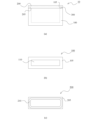
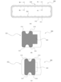
図1~図3を参照して、本発明の実施例1に係る密封構造について説明する。図1は本発明の実施例1に係る密封構造を有するケースの説明図であり、図1(a)はケースの外観図であり、同図(b)はケース本体の平面図であり、同図(c)は蓋部材の底面図である。なお、図1(a)においては、一部透視した部分を点線で示している。図2は本発明の実施例1に係るガスケットの概略図であり、図2(a)はガスケットの平面図であり、同図(b)は同図(a)中のA1-A1断面図であり、同図(c)は同図(a)中のB1-B1断面図である。図3は本発明の実施例1に係る密封構造の説明図であり、図3(a)は蓋部材にガスケットを装着した状態を示す底面図であり、同図(b)は同図(a)中のA2-A2断面図であり、同図(c)は同図(a)中のB2-B2断面図である。
Example 1
A sealing structure according to a first embodiment of the present invention will be described with reference to Figs. 1 to 3. Fig. 1 is an explanatory diagram of a case having a sealing structure according to a first embodiment of the present invention, in which Fig. 1(a) is an external view of the case, Fig. 1(b) is a plan view of the case body, and Fig. 1(c) is a bottom view of the lid member. In Fig. 1(a), a partly see-through portion is indicated by a dotted line. Fig. 2 is a schematic diagram of a gasket according to a first embodiment of the present invention, in which Fig. 2(a) is a plan view of the gasket, Fig. 2(b) is a cross-sectional view taken along A1-A1 in Fig. 2(a), and Fig. 2(c) is a cross-sectional view taken along B1-B1 in Fig. 2(a). Fig. 3 is an explanatory diagram of a sealing structure according to a first embodiment of the present invention, in which Fig. 3(a) is a bottom view showing a state in which the gasket is attached to the lid member, Fig. 3(b) is a cross-sectional view taken along A2-A2 in Fig. 2(a), and Fig. 3(c) is a cross-sectional view taken along B2-B2 in Fig. 2(a).
<密封構造>
図1を参照して、密封構造の概要を説明する。図1に示すケース10は、第1部材としてのケース本体100と、第2部材としての蓋部材200とから構成される。なお、本実施例に係るケース10は、エンジンやトランスミッションのケースとして好適に用いられる。ただし、以下に説明するケースは、このような用途に限らず、各種用途のケースとして適用可能である。なお、本発明の密封構造は、ケースに備えられる密封構造に限らず、2部材の端面間を封止する必要のある各種密封構造に適用可能である。
<Sealing structure>
An outline of the sealing structure will be described with reference to Fig. 1. The
ケース本体100には開口部110が設けられており、開口部110から各種部材や装置が収容される。このケース本体100に蓋部材200が固定されることで、開口部110が塞がれる。ケース本体100と蓋部材200との固定構造については、ボルトなどの固定具を用いる構造の他、各種公知技術を採用し得る。An
そして、ケース本体100と蓋部材200の端面間の隙間を封止するガスケット300が設けられることにより、これらの部材により密封構造が形成される。ガスケット300は、ゴムなどのエラストマー材料により構成される。本実施例においては、蓋部材200に設けられた環状の装着溝210にガスケット300が装着されて、ケース本体100と蓋部材200の端面間の隙間が封止される。すなわち、ガスケット300が、ケース本体100の端面105と、蓋部材200の端面に設けられた環状の装着溝210の溝底面とにより圧縮された状態となることで、これらケース本体100と蓋部材200の端面間の隙間が封止される。なお、ガスケットを装着するための装着溝は、ケース本体に設けてもよいし、ケース本体と蓋部材の両者に設ける構成を採用することもできる。
Then, a
<ガスケット>
特に、図2を参照して、ガスケット300の構成について説明する。ガスケット300は、装着溝210に装着される環状のガスケット本体部310と、ガスケット本体部310の内周面に、周方向に間隔を空けて複数設けられる突起320とを備えている。ガスケット本体部310は、装着溝210に沿うように、平面形状が装着溝210と相似形状の部分(便宜上、以下、「相似形状部分311」と称する)と、蛇行部分312とから構成される。蛇行部分312は、突起320の突出方向と同じ方向(本実施例では外周面から内周面に向かう方向)に向かって突出するように蛇行する形状である。
<Gasket>
The configuration of the
また、本実施例においては、ガスケット本体部310の表裏面のうちの一方の面側に、一対の環状のシール突起313,314が設けられ、他方の面側にも一対の環状のシール突起315,316が設けられている。本実施例においては、ガスケット300の表裏面方向の中心面に対して、ガスケット300は対称形状となっているため、ガスケット300を装着溝210に装着する際に、その方向を気にする必要はない。なお、本発明においては、ガスケット本体部の表裏面にシール突起を備えていない構成、表裏面にそれぞれ単一の環状のシール突起を備える構成、及び、表裏面にそれぞれ3つ以上の環状のシール突起を備える構成も採用し得る。また、本発明においては、ガスケットの表裏面方向の中心面に対して、非対称形状となる構成も採用し得る。この場合、ガスケット本体部の表裏面のうちの一方の面側に単一の環状のシール突起を設け、他方の面側に一対の環状のシール突起を設ける構成など、両面の環状のシール突起の数が異なる構成も採用し得る。勿論、一方の面側には環状のシール突起を設けずに、他方の面側に単一又は複数の環状のシール突起を設ける構成も採用し得る。In this embodiment, a pair of
<装着溝に装着されるガスケット>
特に図3を参照して、ガスケット300が装着溝210に装着され、かつ、ケース本体100と蓋部材200とが固定される前の状態におけるガスケット300と装着溝210との関係について説明する。この状態においては、複数の突起320は装着溝210の片側の側壁面(本実施例においては、内周側の側壁面)に接触するように構成されている。これにより、ガスケット300が装着溝210から脱落してしまうことを抑制することができる。つまり、複数の突起320は、脱落防止用の突起としての役割を担っている。また、上記の状態において、ガスケット本体部310のうち蛇行部分312を除く部分(つまり、相似形状部分311)は、装着溝210の両側の側壁面のうち突起320が接触する側壁面とは反対側の側壁面(本実施例においては、外周側の側壁面)に接触するように構成されている。これにより、ガスケット300が装着溝210から脱落してしまうことをより確実に抑制することができる。
<Gasket installed in the installation groove>
With particular reference to FIG. 3, the relationship between the
そして、本実施例においては、上記の状態において、蛇行部分312は、装着溝210の両側の側壁面に接触しないように構成されている(図3(a)(c)参照)。なお、ケース本体100と蓋部材200とを固定した状態においては、ガスケット300は、これらにより圧縮されて変形する。この状態においては、蛇行部分312の両側面の一部又は全部が装着溝210の両側の側壁面に接触するように構成しても構わない。In this embodiment, in the above state, the
<本実施例に係る密封構造の優れた点>
本実施例に係る密封構造によれば、ガスケット本体部310は、装着溝210の両側の側壁面に接触しない蛇行部分312を有する構成が採用されている。これにより、装着溝210にガスケット300を装着することで、ガスケット本体部310のうち隣り合う突起320間の部分を圧縮する力が作用しても、蛇行部分312により吸収される。つまり、蛇行部分312と装着溝210の側壁面との間には隙間があるため、上記のような力が作用しても、蛇行部分312は、外周面から内周面に向かう方向に向かってより一層突出するように変形することが可能である。これにより、上記の力を逃がすことができる。従って、ガスケット本体部310の一部が、装着溝210から浮き上がるように変形する力は抑制され、浮き上がりを抑制することができる。以上より、ガスケット300の装着溝210への装着作業性を高めることができる。
<Advantages of the sealing structure according to this embodiment>
According to the sealing structure of this embodiment, the
(実施例2)
図4には、本発明の実施例2が示されている。上記実施例1では、突起がガスケット本体部の内周面に設けられる構成を示したが、本実施例においては、突起がガスケット本体部の外周面に設けられる構成を示す。その他の基本的な構成および作用については実施例1と同一なので、同一の構成部分については同一の符号を付して、その説明は省略する。
Example 2
4 shows a second embodiment of the present invention. In the first embodiment, the protrusions are provided on the inner peripheral surface of the gasket body, but in this embodiment, the protrusions are provided on the outer peripheral surface of the gasket body. Since the other basic configurations and functions are the same as those in the first embodiment, the same components are denoted by the same reference numerals and their description is omitted.
図4は本発明の実施例2に係る密封構造の説明図であり、図4(a)はガスケットの平面図であり、同図(b)は蓋部材にガスケットを装着した状態を示す底面図である。本実施例に係るガスケット300Aは、装着溝210に装着される環状のガスケット本体部310Aと、ガスケット本体部310Aの外周面に、周方向に間隔を空けて複数設けられる突起320Aとを備えている。ガスケット本体部310Aは、装着溝210に沿うように、平面形状が装着溝210と相似形状の相似形状部分311Aと、蛇行部分312Aとから構成される。蛇行部分312Aは、突起320Aの突出方向と同じ方向(本実施例では内周面から外周面に向かう方向)に向かって突出するように蛇行する形状である。4 is an explanatory diagram of a sealing structure according to a second embodiment of the present invention, in which FIG. 4(a) is a plan view of the gasket, and FIG. 4(b) is a bottom view showing the state in which the gasket is attached to the lid member. The
また、本実施例においても、実施例1と同様に、ガスケット本体部310Aの表裏面には環状のシール突起が設けられる。環状のシール突起については、実施例1で説明した通りであるので、その説明は省略する。In this embodiment, as in embodiment 1, annular sealing protrusions are provided on the front and back surfaces of the
ガスケット300Aが装着溝210に装着され、かつ、ケース本体100と蓋部材200とが固定される前の状態におけるガスケット300Aと装着溝210との関係について説明する。この状態においては、複数の突起320Aは装着溝210の片側の側壁面(本実施例においては、外周側の側壁面)に接触するように構成されている。これにより、ガスケット300Aが装着溝210から脱落してしまうことを抑制することができる。つまり、複数の突起320Aは、脱落防止用の突起としての役割を担っている。また、上記の状態において、ガスケット本体部310Aのうち蛇行部分312Aを除く部分(つまり、相似形状部分311A)は、装着溝210の両側の側壁面のうち突起320Aが接触する側壁面とは反対側の側壁面(本実施例においては、内周側の側壁面)に接触するように構成されている。これにより、ガスケット300Aが装着溝210から脱落してしまうことをより確実に抑制することができる。The relationship between the
そして、本実施例においては、上記の状態において、蛇行部分312Aは、装着溝210の両側の側壁面に接触しないように構成されている(図4(b)参照)。なお、ケース本体100と蓋部材200とを固定した状態においては、ガスケット300Aは、これらにより圧縮されて変形する。この状態においては、蛇行部分312Aの両側面の一部又は全部が装着溝210の両側の側壁面に接触するように構成しても構わない。In this embodiment, in the above state, the
以上のように構成される本実施例に係る密封構造においても、上記実施例1と同様の効果を得ることができる。The sealing structure of this embodiment configured as described above can also achieve the same effects as in Example 1 above.
(変形例)
図5及び図6を参照して、ガスケットの変形例について説明する。上記実施例1のガスケット300においては、蛇行部分312が、突起320の突出方向と同じ方向(外周面から内周面に向かう方向)に向かって突出するように蛇行する形状により構成される場合を示した。しかしながら、蛇行部分は突起の突出方向と反対方向に向かって突出するように蛇行する形状により構成しても構わない。図5(a)には、蛇行部分312Bが突起320の突出方向と反対方向(内周面から外周面に向かう方向)に向かって突出するように蛇行する形状により構成されるガスケット300Bが示されている。なお、図5(a)はガスケット300Bの平面図であり、実施例1と同一の構成部分には同一の符号が付されている。このガスケット300Bにおいても、実施例1の場合と同様に、装着溝210に装着され、かつ、ケース本体と蓋部材とが固定される前の状態においては、突起320だけでなく、突起320の反対側(真裏)の部位も、装着溝210の側壁面に接触するようにするのが望ましい。これにより、ガスケット300Bが装着溝210から脱落してしまうことをより確実に抑制することができる。なお、上記の状態において、蛇行部分312Bが、装着溝210の両側の側壁面に接触しないように構成される点は、実施例1と同様である。図5(b)には、装着溝210に装着されたガスケット300Bの様子が示されている。
(Modification)
A modified example of the gasket will be described with reference to Figs. 5 and 6. In the
また、実施例2のガスケット300Aについても同様に、蛇行部分が突起の突出方向と反対方向に向かって突出するように蛇行する形状により構成することもできる。すなわち、図5(c)に示すように、蛇行部分312Cが突起320の突出方向と反対方向(外周面から内周面に向かう方向)に向かって突出するように蛇行する形状により構成されるガスケット300Cを採用することもできる。ガスケット300Cが装着溝に装着され、かつケース本体と蓋部材とが固定される前の状態に関しては、上記実施例及び変形例と同様であるので、その説明は省略する。Similarly, the
また、突起の個数や配置については、特に限定されるものではない。例えば、実施例1においては、ガスケット300の長手方向における隣り合う蛇行部分312間の相似形状部分311に対し、それぞれ1か所に突起320が設けられる構成を示した。しかしながら、例えば、図6(a)に示すガスケット300Dのように、突起320を設ける相似形状部分311と突起320が設けられない相似形状部分311を適宜の位置に配置する構成を採用することもできる。また、特に図示はしないが、一か所の相似形状部分311に対して複数の突起320を設ける構成を採用することもできる。
The number and arrangement of the protrusions are not particularly limited. For example, in Example 1, a configuration was shown in which a
また、上記各実施例においては、蛇行部分は、平面形状において、内周面側か外周面側のいずれか一方にのみ湾曲するように構成される場合を示した。しかしながら、例えば、図6(b)(c)に示すように、内周面側と外周面側にそれぞれ湾曲する蛇行部分312X,312Yを採用することもできる。内周面側や外周面側に湾曲する部分の個数が限定されないことは言うまでもない。In addition, in each of the above embodiments, the meandering portion is configured to be curved only toward either the inner circumferential surface side or the outer circumferential surface side in the planar shape. However, for example, as shown in Figures 6(b) and (c), meandering
また、図6(d)に示すガスケット300Eのように、突起320Eに空洞321を設ける構成を採用することもできる。なお、図6(d)は、図2(b)と同様に、図2(a)中のA1-A1断面図に相当する図である。このように、突起320Eに空洞321を設ける構成を採用することで、突起320Eが圧縮される際の反発力が抑制される。これにより、装着溝にガスケット300Eを装着する際に、ガスケット300Eの浮き上がりをより一層抑制することができる。
It is also possible to adopt a configuration in which a
なお、上記各実施例及び変形例においては、蛇行部分が複数か所に設けられる構成を示したが、ガスケット及び装着溝の寸法などの関係で、ガスケットの浮き上がりが抑制できれば、蛇行部分は少なくとも一か所に設ければよい。In addition, in each of the above embodiments and modified examples, a configuration in which the serpentine portion is provided in multiple locations is shown, but if the floating of the gasket can be suppressed due to factors such as the dimensions of the gasket and the mounting groove, the serpentine portion may be provided in at least one location.
10:ケース
100:ケース本体
105:端面
110:開口部
200:蓋部材
210:装着溝
300,300A,300B,300C,300D,300E:ガスケット
310,310A:ガスケット本体部
311,311A:相似形状部分
312,312A,312B,312C,312X,312Y:蛇行部分
313,314,315,316:シール突起
320,320A,320E:突起
321:空洞
10: Case 100: Case body 105: End face 110: Opening 200: Lid member 210: Mounting
Claims (3)
第1部材に固定される第2部材と、
第1部材及び第2部材のうちの少なくともいずれか一方に設けられた環状の装着溝に装着されて、第1部材と第2部材の端面間の隙間を封止するガスケットと、
を備える密封構造であって、
前記ガスケットは、
前記装着溝に装着される環状のガスケット本体部と、
前記ガスケット本体部の内周面又は外周面に、周方向に間隔を空けて複数設けられる突起と、
を備えると共に、
前記ガスケットが前記装着溝に装着され、かつ、第1部材と第2部材が固定される前の状態において、前記突起は前記装着溝の片側の側壁面に接触すると共に、前記ガスケット本体部は、前記装着溝の両側の側壁面に接触しない蛇行部分を有することを特徴とする密封構造。 A first member;
A second member fixed to the first member;
a gasket that is attached to an annular attachment groove provided in at least one of the first member and the second member and seals a gap between end faces of the first member and the second member;
A sealing structure comprising:
The gasket is
an annular gasket body portion that is fitted into the fitting groove;
A plurality of protrusions are provided at intervals in the circumferential direction on an inner circumferential surface or an outer circumferential surface of the gasket body;
With
A sealing structure characterized in that, when the gasket is installed in the installation groove and before the first and second members are fixed, the protrusion contacts one side wall surface of the installation groove, and the gasket main body has a serpentine portion that does not contact both side wall surfaces of the installation groove.
Applications Claiming Priority (3)
| Application Number | Priority Date | Filing Date | Title |
|---|---|---|---|
| JP2023083137 | 2023-05-19 | ||
| JP2023083137 | 2023-05-19 | ||
| PCT/JP2024/016407 WO2024241833A1 (en) | 2023-05-19 | 2024-04-26 | Sealing structure |
Publications (2)
| Publication Number | Publication Date |
|---|---|
| JPWO2024241833A1 JPWO2024241833A1 (en) | 2024-11-28 |
| JP7635472B1 true JP7635472B1 (en) | 2025-02-25 |
Family
ID=93589336
Family Applications (1)
| Application Number | Title | Priority Date | Filing Date |
|---|---|---|---|
| JP2024573754A Active JP7635472B1 (en) | 2023-05-19 | 2024-04-26 | Sealed structure |
Country Status (4)
| Country | Link |
|---|---|
| EP (1) | EP4715240A1 (en) |
| JP (1) | JP7635472B1 (en) |
| CN (1) | CN120917253A (en) |
| WO (1) | WO2024241833A1 (en) |
Citations (5)
| Publication number | Priority date | Publication date | Assignee | Title |
|---|---|---|---|---|
| JP2002340190A (en) * | 2001-05-15 | 2002-11-27 | Uchiyama Mfg Corp | Gasket |
| JP2005016621A (en) * | 2003-06-26 | 2005-01-20 | Nok Corp | Gasket |
| WO2007007611A1 (en) * | 2005-07-07 | 2007-01-18 | Nok Corporation | Gasket |
| JP2009210049A (en) * | 2008-03-05 | 2009-09-17 | Nok Corp | Gasket |
| JP2021173331A (en) * | 2020-04-24 | 2021-11-01 | Nok株式会社 | Gasket and sealing structure |
-
2024
- 2024-04-26 WO PCT/JP2024/016407 patent/WO2024241833A1/en not_active Ceased
- 2024-04-26 EP EP24810841.7A patent/EP4715240A1/en active Pending
- 2024-04-26 JP JP2024573754A patent/JP7635472B1/en active Active
- 2024-04-26 CN CN202480019086.4A patent/CN120917253A/en active Pending
Patent Citations (5)
| Publication number | Priority date | Publication date | Assignee | Title |
|---|---|---|---|---|
| JP2002340190A (en) * | 2001-05-15 | 2002-11-27 | Uchiyama Mfg Corp | Gasket |
| JP2005016621A (en) * | 2003-06-26 | 2005-01-20 | Nok Corp | Gasket |
| WO2007007611A1 (en) * | 2005-07-07 | 2007-01-18 | Nok Corporation | Gasket |
| JP2009210049A (en) * | 2008-03-05 | 2009-09-17 | Nok Corp | Gasket |
| JP2021173331A (en) * | 2020-04-24 | 2021-11-01 | Nok株式会社 | Gasket and sealing structure |
Also Published As
| Publication number | Publication date |
|---|---|
| CN120917253A (en) | 2025-11-07 |
| JPWO2024241833A1 (en) | 2024-11-28 |
| WO2024241833A1 (en) | 2024-11-28 |
| EP4715240A1 (en) | 2026-03-25 |
Similar Documents
| Publication | Publication Date | Title |
|---|---|---|
| JP3349132B2 (en) | Low load seal | |
| WO2012161258A1 (en) | Sealing structure | |
| WO2010143488A1 (en) | Gasket for small size electronic appliance | |
| WO2007007612A1 (en) | Gasket | |
| JP2011094667A (en) | Gasket and sealing structure | |
| JP7635472B1 (en) | Sealed structure | |
| JP7599569B2 (en) | gasket | |
| JP2004204941A (en) | Gasket | |
| JP7391675B2 (en) | sealing device | |
| JP4128802B2 (en) | Plasma resistant seal | |
| JP2011047508A (en) | Gasket | |
| JP2009210049A (en) | Gasket | |
| JP2003329140A (en) | Gasket | |
| JP5250469B2 (en) | Sealing structure and gasket | |
| JP7695362B2 (en) | sealing device | |
| CN213711868U (en) | Sealing device and sealing structure | |
| JP7459249B2 (en) | sealing device | |
| CN222963335U (en) | Gasket ring | |
| JP7808289B2 (en) | Seal Structure | |
| JP4805568B2 (en) | Seal structure | |
| JP7177195B2 (en) | Gaskets and sealing devices | |
| JP7411221B2 (en) | Seal member | |
| JPS6121357Y2 (en) | ||
| JP4324782B2 (en) | Sealing device | |
| JPWO2018123214A1 (en) | Metal gasket |
Legal Events
| Date | Code | Title | Description |
|---|---|---|---|
| A621 | Written request for application examination |
Free format text: JAPANESE INTERMEDIATE CODE: A621 Effective date: 20241216 |
|
| A871 | Explanation of circumstances concerning accelerated examination |
Free format text: JAPANESE INTERMEDIATE CODE: A871 Effective date: 20241216 |
|
| TRDD | Decision of grant or rejection written | ||
| A01 | Written decision to grant a patent or to grant a registration (utility model) |
Free format text: JAPANESE INTERMEDIATE CODE: A01 Effective date: 20250128 |
|
| A61 | First payment of annual fees (during grant procedure) |
Free format text: JAPANESE INTERMEDIATE CODE: A61 Effective date: 20250212 |
|
| R150 | Certificate of patent or registration of utility model |
Ref document number: 7635472 Country of ref document: JP Free format text: JAPANESE INTERMEDIATE CODE: R150 |