JP7635455B2 - Clamp - Google Patents
Clamp Download PDFInfo
- Publication number
- JP7635455B2 JP7635455B2 JP2024139376A JP2024139376A JP7635455B2 JP 7635455 B2 JP7635455 B2 JP 7635455B2 JP 2024139376 A JP2024139376 A JP 2024139376A JP 2024139376 A JP2024139376 A JP 2024139376A JP 7635455 B2 JP7635455 B2 JP 7635455B2
- Authority
- JP
- Japan
- Prior art keywords
- clamp
- sidewall
- pressing
- pressing portion
- tube
- Prior art date
- Legal status (The legal status is an assumption and is not a legal conclusion. Google has not performed a legal analysis and makes no representation as to the accuracy of the status listed.)
- Active
Links
- 230000000903 blocking effect Effects 0.000 claims description 12
- 238000003780 insertion Methods 0.000 description 12
- 230000037431 insertion Effects 0.000 description 12
- 230000007246 mechanism Effects 0.000 description 12
- 239000008280 blood Substances 0.000 description 5
- 210000004369 blood Anatomy 0.000 description 5
- 210000000078 claw Anatomy 0.000 description 5
- 230000000052 comparative effect Effects 0.000 description 4
- 238000013459 approach Methods 0.000 description 3
- 230000005489 elastic deformation Effects 0.000 description 3
- 239000000463 material Substances 0.000 description 3
- 230000007423 decrease Effects 0.000 description 2
- 238000006073 displacement reaction Methods 0.000 description 2
- 238000001802 infusion Methods 0.000 description 2
- 238000000034 method Methods 0.000 description 2
- 230000000149 penetrating effect Effects 0.000 description 2
- 239000011347 resin Substances 0.000 description 2
- 229920005989 resin Polymers 0.000 description 2
- 230000000694 effects Effects 0.000 description 1
- 238000012986 modification Methods 0.000 description 1
- 230000004048 modification Effects 0.000 description 1
- 230000008569 process Effects 0.000 description 1
- 230000000284 resting effect Effects 0.000 description 1
- 238000000926 separation method Methods 0.000 description 1
Images


Classifications
-
- F—MECHANICAL ENGINEERING; LIGHTING; HEATING; WEAPONS; BLASTING
- F16—ENGINEERING ELEMENTS AND UNITS; GENERAL MEASURES FOR PRODUCING AND MAINTAINING EFFECTIVE FUNCTIONING OF MACHINES OR INSTALLATIONS; THERMAL INSULATION IN GENERAL
- F16K—VALVES; TAPS; COCKS; ACTUATING-FLOATS; DEVICES FOR VENTING OR AERATING
- F16K7/00—Diaphragm valves or cut-off apparatus, e.g. with a member deformed, but not moved bodily, to close the passage ; Pinch valves
- F16K7/02—Diaphragm valves or cut-off apparatus, e.g. with a member deformed, but not moved bodily, to close the passage ; Pinch valves with tubular diaphragm
- F16K7/04—Diaphragm valves or cut-off apparatus, e.g. with a member deformed, but not moved bodily, to close the passage ; Pinch valves with tubular diaphragm constrictable by external radial force
- F16K7/06—Diaphragm valves or cut-off apparatus, e.g. with a member deformed, but not moved bodily, to close the passage ; Pinch valves with tubular diaphragm constrictable by external radial force by means of a screw-spindle, cam, or other mechanical means
- F16K7/063—Lever clamps
-
- A—HUMAN NECESSITIES
- A61—MEDICAL OR VETERINARY SCIENCE; HYGIENE
- A61M—DEVICES FOR INTRODUCING MEDIA INTO, OR ONTO, THE BODY; DEVICES FOR TRANSDUCING BODY MEDIA OR FOR TAKING MEDIA FROM THE BODY; DEVICES FOR PRODUCING OR ENDING SLEEP OR STUPOR
- A61M39/00—Tubes, tube connectors, tube couplings, valves, access sites or the like, specially adapted for medical use
- A61M39/22—Valves or arrangement of valves
- A61M39/28—Clamping means for squeezing flexible tubes, e.g. roller clamps
- A61M39/284—Lever clamps
-
- F—MECHANICAL ENGINEERING; LIGHTING; HEATING; WEAPONS; BLASTING
- F16—ENGINEERING ELEMENTS AND UNITS; GENERAL MEASURES FOR PRODUCING AND MAINTAINING EFFECTIVE FUNCTIONING OF MACHINES OR INSTALLATIONS; THERMAL INSULATION IN GENERAL
- F16B—DEVICES FOR FASTENING OR SECURING CONSTRUCTIONAL ELEMENTS OR MACHINE PARTS TOGETHER, e.g. NAILS, BOLTS, CIRCLIPS, CLAMPS, CLIPS OR WEDGES; JOINTS OR JOINTING
- F16B2/00—Friction-grip releasable fastenings
- F16B2/02—Clamps, i.e. with gripping action effected by positive means other than the inherent resistance to deformation of the material of the fastening
- F16B2/06—Clamps, i.e. with gripping action effected by positive means other than the inherent resistance to deformation of the material of the fastening external, i.e. with contracting action
- F16B2/10—Clamps, i.e. with gripping action effected by positive means other than the inherent resistance to deformation of the material of the fastening external, i.e. with contracting action using pivoting jaws
-
- A—HUMAN NECESSITIES
- A61—MEDICAL OR VETERINARY SCIENCE; HYGIENE
- A61M—DEVICES FOR INTRODUCING MEDIA INTO, OR ONTO, THE BODY; DEVICES FOR TRANSDUCING BODY MEDIA OR FOR TAKING MEDIA FROM THE BODY; DEVICES FOR PRODUCING OR ENDING SLEEP OR STUPOR
- A61M5/00—Devices for bringing media into the body in a subcutaneous, intra-vascular or intramuscular way; Accessories therefor, e.g. filling or cleaning devices, arm-rests
- A61M5/14—Infusion devices, e.g. infusing by gravity; Blood infusion; Accessories therefor
- A61M5/168—Means for controlling media flow to the body or for metering media to the body, e.g. drip meters, counters ; Monitoring media flow to the body
- A61M5/16804—Flow controllers
- A61M5/16813—Flow controllers by controlling the degree of opening of the flow line
Landscapes
- Health & Medical Sciences (AREA)
- Engineering & Computer Science (AREA)
- Heart & Thoracic Surgery (AREA)
- General Engineering & Computer Science (AREA)
- Animal Behavior & Ethology (AREA)
- Biomedical Technology (AREA)
- Hematology (AREA)
- Life Sciences & Earth Sciences (AREA)
- Anesthesiology (AREA)
- General Health & Medical Sciences (AREA)
- Public Health (AREA)
- Veterinary Medicine (AREA)
- Pulmonology (AREA)
- Mechanical Engineering (AREA)
- Vascular Medicine (AREA)
- Infusion, Injection, And Reservoir Apparatuses (AREA)
- Clamps And Clips (AREA)
Description
本発明は、柔軟性を有するチューブを閉塞するためのクランプに関する。 The present invention relates to a clamp for occluding a flexible tube.
採血セットの血液バッグ等を繋ぐ流路や、輸液セットのバッグ等を接続する流路として、柔軟性を有する医療用チューブが用いられており、これらの医療用チューブには、流路を閉塞するためのクランプが取り付けられている。 Flexible medical tubes are used as flow paths connecting blood bags in blood collection sets and bags in infusion sets, and clamps are attached to these medical tubes to block the flow paths.
クランプは、医療用チューブが挿通される孔部と、挿通された医療用チューブを圧迫して閉塞させる押圧部と、押圧部に操作力を入力するための可動部と、可動部を押圧状態に保つロック機構とを備えている。クランプは、初期状態において、可動部の弾発力により押圧部が開いている。使用者が、可動部を押圧すると、押圧部がチューブを圧迫して閉塞させ、可動部がロック機構にロックされることで押圧部がチューブを閉塞した状態に維持される。 The clamp has a hole through which the medical tube is inserted, a pressing part that compresses and closes the inserted medical tube, a movable part for inputting an operating force to the pressing part, and a locking mechanism that keeps the movable part in a pressed state. In the initial state of the clamp, the pressing part is open due to the elastic force of the movable part. When a user presses the movable part, the pressing part compresses and closes the tube, and the movable part is locked by the locking mechanism, so that the pressing part maintains the state in which it closes the tube.
ところで、多数の血液バッグを処理する血液センター等では、使用者が多数のクランプを閉塞させる操作を連続的に行う場合がある。また、多忙な医療現場において、使用者が迅速にクランプを閉塞する操作が発生する場合がある。このような場合には、使用者は手元を目視で確認せずに片手でクランプの操作を行なうことがある。まれに、クランプにおいて、医療用チューブが押圧部から横ずれした状態のまま圧迫されてしまい、流路の閉塞が不完全となるおそれがある。 In blood centers and other facilities that process a large number of blood bags, users may need to continuously close a large number of clamps. Also, in busy medical settings, users may need to quickly close a clamp. In such cases, users may operate the clamp with one hand without visually checking what is in front of them. In rare cases, the clamp may compress the medical tube while it is shifted sideways from the pressing part, which may result in incomplete closure of the flow path.
このような医療用チューブの流路の不完全な閉塞を防ぐために、特開2018-000836号公報には、押圧部の両側部に一対のサイドウォールを設けて、医療用チューブの横ずれを防ぐ技術が記載されている。 To prevent such incomplete blockage of the flow path of the medical tube, JP 2018-000836 A describes a technique for preventing lateral displacement of the medical tube by providing a pair of side walls on both sides of the pressing part.
しかしながら、上記のクランプでは、押圧部がサイドウォールに乗り上げたまま可動部がロック機構でロックされてしまい、押圧部が完全に医療用チューブを閉塞しない場合が生じるといった、新たな問題が発生することが判明した。 However, it was discovered that the above clamp creates a new problem: the pressing part may ride up on the sidewall and the movable part may become locked by the locking mechanism, causing the pressing part to not completely block the medical tube.
そこで、本発明は、医療用チューブを確実に閉塞できるクランプを提供することを目的とする。 Therefore, the present invention aims to provide a clamp that can reliably close medical tubing.
以下の開示の一観点は、上部にチューブが載置される固定部と、前記固定部の上方で前記固定部と対向する可動部と、前記可動部を前記固定部に向けて押圧した際に前記チューブを圧迫して閉塞させる閉塞部と、を備え、前記閉塞部は、前記可動部から前記固定部に向けて突出し前記チューブを押圧する押圧部と、前記固定部の両側部から壁状に延び出て前記チューブの横ずれを阻止する一対のサイドウォールと、前記押圧部に設けられ、前記押圧部を前記サイドウォールの間に呼び込む案内構造と、を有し、前記案内構造は、前記押圧部の側部に形成された球面よりなり、前記固定部と前記サイドウォールとの境界部分に前記球面の曲率と同じ曲率で湾曲する隆起部が形成されている、クランプにある。 One aspect of the disclosure below is a clamp comprising a fixed part on which a tube is placed, a movable part above the fixed part and facing the fixed part, and a blocking part that compresses and blocks the tube when the movable part is pressed toward the fixed part, the blocking part having a pressing part that protrudes from the movable part toward the fixed part and presses the tube, a pair of sidewalls that extend like walls from both sides of the fixed part and prevent lateral displacement of the tube, and a guide structure that is provided on the pressing part and guides the pressing part between the sidewalls, the guide structure being made of a spherical surface formed on the side of the pressing part, and a raised part that curves with the same curvature as the curvature of the spherical surface is formed at the boundary between the fixed part and the sidewall.
上記観点のクランプによれば、押圧部がサイドウォールに乗り上げた場合であっても、案内構造により押圧部がサイドウォールの内側に呼び込まれるため、医療用チューブを確実に閉塞できる。 With the clamp described above, even if the pressing portion rides up onto the sidewall, the guide structure guides the pressing portion to the inside of the sidewall, ensuring that the medical tube is closed.
以下、本発明のクランプについて好適な実施形態を挙げ、添付の図面を参照して詳細に説明する。 Below, we present a preferred embodiment of the clamp of the present invention and explain it in detail with reference to the attached drawings.
(第1実施形態)
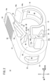
図1に示す本実施形態に係るクランプ10は、樹脂素材によって一体的に形成されており、血液チューブや輸液チューブ等の医療用チューブ80に装着されて、医療用チューブ80の閉塞及び開放といった操作に用いられる。図1に示すように、クランプ10は、医療用チューブ80が載置される固定部12と、固定部12の上方に対向して配置された可動部14と、固定部12と可動部14とを繋ぐ湾曲部16と、湾曲部16に対向する起立部18と、医療用チューブ80を閉塞するための閉塞部20とを有する。
First Embodiment
1 is integrally formed from a resin material and is attached to a
固定部12は、前後方向に長く延びた板状の部分であり、上部に医療用チューブ80が載置される。固定部12の後端部からは湾曲部16が固定部12の上方に向けて延び出ている。また、固定部12の前端部からは、起立部18が固定部12の上方に向けて延び出ている。固定部12の前後方向の中央部には、閉塞部20の一部を構成する台座部22と、固定部12の幅方向の両側部から上方に延び出た一対のサイドウォール24とが形成されている。
The
湾曲部16は、固定部12から上方に向けて延び出た部材であり、側面視して半円形に湾曲している。湾曲部16は、曲率半径を縮小又は増加させる方向に弾性変形が可能となっている。湾曲部16の中央部には、厚さ方向(前後方向)に貫通形成された第1挿通孔28が形成されている。第1挿通孔28は、医療用チューブ80を固定部12と可動部14との間のチューブ配置空間30に導入するための孔であり、医療用チューブ80が挿通可能な幅方向の寸法及び上下方向の寸法に形成されている。第1挿通孔28の両側部には、一対の柱部32が形成されている。この柱部32により、湾曲部16の弾性変形の際の硬さ(バネ定数)が決まる。
The
湾曲部16の上端は可動部14の後端に一体的に繋がっている。湾曲部16が弾性変形することにより、可動部14が湾曲部16の後端を中心に回動し、可動部14が固定部12の上下方向に変位可能となっている。
The upper end of the
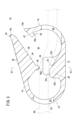
可動部14は、板状の部材でありその先端部14aは固定部12の前端の上方に配置されている。可動部14の先端部14aの上側には、後述するロック機構部44に係合するための爪部34が形成されている。爪部34は、幅方向に線状に延びて形成されている。図2に示すように、可動部14の上面には、幅方向に延びる線状の突起よりなる棟部36が複数本設けられている。これらの棟部36は使用者が可動部14に操作力を入力する際の滑り止めとして機能する。
The
可動部14の下側には、閉塞部20の一部を構成する突起部38と押圧部40とが形成されている。突起部38と押圧部40の詳細は、閉塞部20の説明で後述する。
A
一方、固定部12の前端からは、起立部18が固定部12の上方に向けて延び出ている。起立部18は、側面視して円弧状に湾曲しながら上方に向けて延びており、その上端部18aには、可動部14の先端部14aの下部と当接する傾斜面42と、爪部34と係合するロック機構部44とが形成されている。傾斜面42は、後方に向かうにつれて下側に下るように傾斜した面として形成されている。傾斜面42は、可動部14を押圧すると、可動部14の先端部14aと当接して摺動させ、可動部14の先端部14aをロック機構部44に導く。可動部14からの押圧力が傾斜面42に作用すると、起立部18が前方に押し広げられるように湾曲する。
On the other hand, the standing
ロック機構部44は、幅方向に延びる上に凹の溝44aを備えたフック状の部分である。ロック機構部44は、可動部14を押し下げた際に先端部14aの爪部34と係合して、可動部14の上方への復帰を阻止し、可動部14を下方に押し下げた状態(押圧状態)にロックする。
The
起立部18のロック機構部44の下側には、第2挿通孔46が形成されている。第2挿通孔46は、起立部18を厚さ方向(前後方向)に貫通して形成されている。第2挿通孔46は、前方から見て矩形状に形成されている。第2挿通孔46の幅方向の寸法及び上下方向の寸法は、医療用チューブ80の直径よりも大きく形成されており、医療用チューブ80を挿通させることができる。
A
図1に示すように、医療用チューブ80は、湾曲部16の第1挿通孔28と、起立部18の第2挿通孔46を通じて、固定部12と可動部14との間のチューブ配置空間30に導入される。そして、閉塞部20により、医療用チューブ80の閉塞が行われる。
As shown in FIG. 1, the
以下、閉塞部20について説明する。図1に示すように、閉塞部20は、固定部12側に形成された、台座部22及びサイドウォール24と、可動部14側に形成された突起部38及び押圧部40とを備える。
The blocking
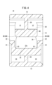
このうち、台座部22は、緩やかに傾斜した前面22aと、図2に示すように、固定部12に略垂直に切り立った後面22bと、前面22aと後面22bとの上端間に形成され、固定部12に平行な上端面22cとを備える。上端面22cは、可動部14を押圧した際に、後述する押圧部40と当接可能な位置に形成されており、医療用チューブ80を下方から支持する部分となる。台座部22は、両側部が肉抜部25によって肉抜きされている。台座部22は、図4に示すように、幅方向の中央に設けられたリブ26によって下方から支持されている。
The
サイドウォール24は、台座部22の両側部に一対設けられている。サイドウォール24は、固定部12の側部に沿って、固定部12の上方に壁状に延び出て形成されている。サイドウォール24は、上端面22cよりも上方に突出することにより、医療用チューブ80の横ずれを阻止する。
A pair of
一方、突起部38は、可動部14の下面側から、固定部12に向けて突出して形成されている。突起部38は、側面視して、下端側に頂部を有する三角形に形成されている。突起部38の幅方向の寸法は、一対のサイドウォール24の距離よりも小さく形成されており、サイドウォール24の内側に挿入可能となっている。突起部38は、両側部が肉抜部37によって肉抜きされている。また、突起部38は、図4に示すように、幅方向の中央に設けられたリブ39によって上方の可動部14側から支持されている。突起部38の下端には、押圧部40が形成されている。
On the other hand, the
押圧部40は、台座部22の上端面22cの近傍の上方に配置されており、突起部38の下端に突出して設けられている。押圧部40は、幅方向に中心軸を有する円柱状に形成されており、幅方向に延びる線状の当接部分40aを通じて医療用チューブ80を圧迫して閉塞させる。押圧部40は、一対のサイドウォール24の間に挿入可能とするべく、一対のサイドウォール24の間隙(幅方向の離間距離)よりも、幅方向の寸法が短く形成されている。また、押圧部40の幅方向の両側部には、下端に向かうにつれて押圧部40の幅方向の寸法が小さくなるように傾斜した第1傾斜構造48が形成されている。本実施形態において、第1傾斜構造48は、図1、図2、及び図4に示すように、球面50として構成されている。
The
また、図4に示すように、台座部22の上端面22cとサイドウォール24との境界部分には、押圧部40を上端面22cに当接させたときに生じる間隙を埋めるべく、球面50の曲率と同じ曲率で湾曲する隆起部52が形成されている。隆起部52は、台座部22とサイドウォール24の付け根に沿って前後方向に延びて形成されている。隆起部52はサイドウォール24の前後方向の全域に亘って形成されている。このような隆起部52を設けることにより、サイドウォール24が補強される。また、隆起部52により、サイドウォール24に外力が作用した際にサイドウォール24の付け根に応力が集中するのを防ぐことができ、サイドウォール24の破損を防止できる。
As shown in FIG. 4, a raised
本実施形態のクランプ10は以上のように構成され、以下その作用について説明する。
The
図1及び図3に示すように、クランプ10は、第1挿通孔28及び第2挿通孔46に医療用チューブ80を挿通させて使用される。医療用チューブ80は、固定部12と可動部14との間であって、一対のサイドウォール24の間に配置されて、チューブ配置空間30内に保持される。
As shown in Figures 1 and 3, the
使用者が可動部14の先端部14aが固定部12側に接近するように押圧すると、湾曲部16は、その曲率半径が小さくなるように弾性変形する。そして、可動部14が固定部12に接近するように変位する。図6Aに示すように、医療用チューブ80は、押圧部40と台座部22の上端面22cとの間に挟まれつつ圧迫される。更に可動部14を押圧すると、図1に示す可動部14の先端部14aが起立部18の傾斜面42に当接しつつ摺動する。可動部14が押し下げられるにしたがって、傾斜面42を介して起立部18を前方に倒す方向の荷重が作用し、起立部18の上端が前方に傾くように変形する。そして、可動部14の爪部34が、起立部18のロック機構部44に引っ掛かることで、可動部14がロック機構部44に固定される。
When the user presses the
クランプ10においては、湾曲部16に医療用チューブ80を挿通するための第1挿通孔28が形成されているため、湾曲部16の剛性が低くなっている。そのため、使用者が可動部14を押圧する操作を行った際に、その先端部14aが幅方向にずれる場合があり、可動部14の押圧部40がサイドウォール24の上に乗り上げてしまう場合がある。
In the
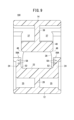
図5に示す比較例のクランプ100は、押圧部40の両側部に第1傾斜構造48を設けない例を示している。比較例のクランプ100では、押圧部40がサイドウォール24の上に乗り上げると、その状態に維持されてしまう。このような場合であっても、可動部14は弾性変形が容易な樹脂素材で形成されているため、比較例のクランプ100では、押圧部40がサイドウォール24の上に乗り上げた状態のまま、可動部14の先端部14aがロック機構部44に固定されてしまう。そして、医療用チューブ80の閉塞が完全には行われない事象が発生する。
The
これに対し、本実施形態のクランプ10では、押圧部40の両側部に球面50よりなる第1傾斜構造48が形成されている。第1傾斜構造48は、下端に向かうにつれて押圧部40の幅方向の寸法が小さくなるように傾斜した曲面で形成されている。そのため、図6Aのように、押圧部40がサイドウォール24の上に乗り上げた場合であっても、矢印に示すように、第1傾斜構造48によって、押圧部40が一対のサイドウォール24の間に呼び込まれる。これにより、本実施形態のクランプ10によれば、図6Bに示すように、押圧部40が一対のサイドウォール24の間に確実に挿入されて、医療用チューブ80の閉塞動作を確実に行うことができる。
In contrast, in the
本実施形態のクランプ10は、以下の効果を奏する。
The
本実施形態のクランプ10は、上部に医療用チューブ80(チューブ)が載置される固定部12と、固定部12の上方で固定部12と対向する可動部14と、可動部14を固定部12に向けて押圧した際に医療用チューブ80を圧迫して閉塞させる閉塞部20と、を備え、閉塞部20は、可動部14から固定部12に向けて突出し、幅方向に延びる線状の当接部分40aで医療用チューブ80を押圧する押圧部40と、固定部12の両側部から壁状に延び出て医療用チューブ80の横ずれを阻止する一対のサイドウォール24と、押圧部40とサイドウォール24の少なくとも一方に設けられ、押圧部40をサイドウォール24の間に呼び込む案内構造としての第1傾斜構造48と、を有する。
The
上記のクランプ10によれば、押圧部40がサイドウォール24に乗り上げた場合であっても、案内構造により押圧部40がサイドウォール24の内側に呼び込まれるため、医療用チューブ80を確実に閉塞できる。
According to the
上記のクランプ10において、第1傾斜構造48は球面50で構成してもよい。この構成によれば、押圧部40をよりスムーズに一対のサイドウォール24の間に呼び込むことができる。
In the
上記のクランプ10において、固定部12とサイドウォール24との境界部分に第1傾斜構造48の形状に対応した隆起部52が形成されていてもよい。この構成によれば、隆起部52が第1傾斜構造48によるクリアランスを埋めることができるため、医療用チューブ80を確実に閉塞することができる。
In the
上記のクランプ10において、隆起部52はサイドウォール24の医療用チューブ80の延在方向の全域に亘って形成されていてもよい。この構成によれば、サイドウォール24の剛性が向上し、サイドウォール24の変形や破損を防ぐことができる。
In the
以上の本実施形態においては、第1傾斜構造48を球面50で構成する例で説明したが、本実施形態はこれに限定されるものではなく、第1傾斜構造48を平坦な傾斜面で構成してもよい。また、第1傾斜構造48を傾斜角度が異なる複数の傾斜面を繋いで構成してもよい。
In the above embodiment, an example has been described in which the first
(第2実施形態)
図7Aに示す本実施形態に係るクランプ10Aは、押圧部40の第1傾斜構造48Aの構成において、図1~図4、図6A、図6Bに示す第1実施形態に係るクランプ10と異なっている。なお、クランプ10Aにおいて、第1傾斜構造48A以外の構成は、第1実施形態に係るクランプ10と同様である。クランプ10Aにおいて、クランプ10と同様の構成については同一符号を付してその詳細な説明は省略する。
Second Embodiment
The
図7Aに示すように、本実施形態のクランプ10Aは、押圧部40の両側部に第1傾斜構造48Aが形成されている。第1傾斜構造48Aは、押圧部40の両側部に形成された切欠部54を備えている。図示の例では、切欠部54は、楔状に形成されているが、これに限定されるものではなく、矩形状又は半円状等の各種の形状を採用することができる。第1傾斜構造48Aは、押圧部40がサイドウォール24に乗り上げていない状態では、傾斜していない。
As shown in FIG. 7A, the
本実施形態のクランプ10Aは以上のように構成され、以下その作用について説明する。
The
図7Bに示すように、クランプ10Aは、押圧部40がサイドウォール24に乗り上げた状態で押圧されると、第1傾斜構造48Aの切欠部54が押しつぶされる。そして、押圧部40には、切欠部54が押しつぶされることで、側部に傾斜面54aが形成される。この傾斜面54aは、下端に向かうにつれて押圧部40の幅方向の寸法が小さくなる向きに傾斜しており、可動部14を固定部12に向けて押圧すると、押圧部40が傾斜面54aによって一対のサイドウォール24の間に導かれる。このように、第1傾斜構造48Aも、押圧部40を一対のサイドウォール24の間に呼び込む構造として機能する。
As shown in FIG. 7B, when the
本実施形態のクランプ10Aは、以下の効果を奏する。
The
クランプ10Aは、案内構造として、押圧部40に形成され、サイドウォール24の上端に当接すると、押圧部40にサイドウォール24の内側に向けて傾斜した傾斜面を形成する第1傾斜構造48Aを有する。
The
上記のクランプ10Aによっても、第1実施形態のクランプ10と同様の効果が得られる。
The
なお、本実施形態のクランプ10Aにおいて、第1傾斜構造48Aは、切欠部54に限定されるものではなく、押圧部40をサイドウォール24に押し付ける荷重の入力によって、他の部分よりも弾性圧縮が進むことで、傾斜面を形成する部材で構成することもできる。例えば、弾性圧縮しやすい材料を押圧部40の両側部に配置することで、第1傾斜構造48Aを構成してもよい。
In the
(第3実施形態)
図8に示す本実施形態のクランプ10Bは、サイドウォール24Aの間に呼び込む案内構造として、サイドウォール24Aの上端に第2傾斜構造56を設けている。なお、本実施形態のクランプ10Bにおいて、第1実施形態に係るクランプ10と同様の構成については、同一符号を付してその詳細な説明は省略する。
Third Embodiment
8, a
クランプ10Bは、押圧部40の両側部に傾斜構造を設ける代わりに、サイドウォール24Aの上端に第2傾斜構造56を設けている。第2傾斜構造56は、一対のサイドウォール24Aの内側に向けて傾斜している。すなわち、図8の左側のサイドウォール24Aの第2傾斜構造56は、左端の側端部から内側(右側)に向かうにつれて下方に下るように傾斜しており、押圧部40の側部をサイドウォール24Aの内側に呼び込む傾斜面となっている。また、右側のサイドウォール24Aの第2傾斜構造56は、右端の側端部から内側(左側)に向かうにつれて下方に下るように傾斜しており、右側のサイドウォール24Aに当接した押圧部40をサイドウォール24Aの内側に呼び込む傾斜面となっている。
Instead of providing an inclined structure on both sides of the
本実施形態のクランプ10Bは、以下の効果を奏する。
The
本実施形態のクランプ10Bは、案内構造として、サイドウォール24Aの上端に形成され、サイドウォール24Aの内側に向けて傾斜した第2傾斜構造56を有する。
In this embodiment, the
上記のクランプ10Bによれば、押圧部40がサイドウォール24Aに乗り上げた場合であっても、第2傾斜構造56により押圧部40がサイドウォール24Aの内側に呼び込まれるため、医療用チューブ80を確実に閉塞できる。
According to the
なお、本実施形態のクランプ10Bにおいて、第2傾斜構造56は、平坦面に限定されるものではなく、球面や放物面等の曲面で構成されてもよい。また、押圧部40側に第1傾斜構造48が形成されていても構わない。
In the
(第4実施形態)
図9に示す本実施形態のクランプ10Cは、サイドウォール24の間に呼び込む案内構造として、サイドウォール24の上端に第2傾斜構造56Aを備えている。なお、本実施形態のクランプ10Cにおいて、第1実施形態に係るクランプ10と同様の構成については、同一符号を付してその詳細な説明は省略する。
Fourth Embodiment
9 includes a second
本実施形態の第2傾斜構造56Aは、サイドウォール24の内側部に形成された切欠部58を有している。ただし、サイドウォール24の上端は、押圧部40と当接しない間は、固定部12の底面と略平行な平坦面で構成されている。図示の例では、押圧部40の両側部に第1傾斜構造48が形成されているが、本実施形態はこれに限定されるものではなく、第1傾斜構造48が形成されていなくてもよい。
The second
本実施形態のクランプ10Cは以上のように構成され、以下その作用について説明する。 The clamp 10C of this embodiment is configured as described above, and its operation will be explained below.
クランプ10Cの可動部14を押圧した際に、押圧部40がサイドウォール24の上端に当接すると、サイドウォール24の上端からの荷重により、第2傾斜構造56Aの切欠部58が押しつぶされる。その結果、サイドウォール24の上端が、内側に傾斜した傾斜面となる。この傾斜面によって、押圧部40がサイドウォール24の間に呼び込まれる。このように、第2傾斜構造56Aは、押圧部40が当接すると傾斜面が現われる構造となっている。
When the
本実施形態のクランプ10Cは、以下の効果を奏する。 The clamp 10C of this embodiment has the following advantages:
クランプ10Cは、案内構造として、サイドウォール24に形成され、押圧部40が当接するとサイドウォール24の上端に内側に傾斜した傾斜面を形成する第2傾斜構造56Aを有する。
The clamp 10C has a second
上記のクランプ10Cによれば、押圧部40がサイドウォール24に乗り上げた場合であっても、第2傾斜構造56Aにより押圧部40をサイドウォール24の内側に呼び込むことができ、医療用チューブ80を確実に閉塞できる。
According to the clamp 10C described above, even if the
(第5実施形態)
図10Aに示すクランプ10Dは、サイドウォール24Aの間に呼び込む案内構造として、サイドウォール24Aに第2傾斜構造56Bが設けられている。なお、本実施形態のクランプ10Dにおいて、第1実施形態に係るクランプ10と同様の構成については、同一符号を付してその詳細な説明は省略する。
Fifth Embodiment
10A, a second
本実施形態のサイドウォール24Aは、枠状に形成されている。サイドウォール24Aの上端は板部材60で構成されている。板部材60は、前端及び後端が支持部60a、60bによって支持されている。板部材60の下側は孔62となっている。
In this embodiment, the
第2傾斜構造56Bは、板部材60の内側に形成された複数の切込溝64を備えている。切込溝64は板部材60の上側から下方向に向けて所定の深さにまで形成されている。なお、切込溝64は、板部材60を上下方向に貫通して形成されていてもよい。また、切込溝64は、板部材60の下側から上方向に向けて切り込むように形成されてもよい。
The second
本実施形態のクランプ10Dは以上のように構成され、以下その作用について説明する。
The
図10Bに示すように、押圧部40がサイドウォール24Aの上端に乗り上げると、押圧部40からの荷重により、板部材60が切込溝64を中心に変形する。切込溝64は内側に形成されているため、図示のように、板部材60は内側に傾くように変形する。そして、板部材60の上面に内側に傾斜した傾斜面が形成される。このように、第2傾斜構造56Bは、押圧部40がサイドウォール24Aに乗り上げた際に、押圧部40を内側に呼び込む傾斜面を形成する。これにより、クランプ10Dは、押圧部40をサイドウォール24Aの間に導いて、医療用チューブ80を確実に閉塞できる。
As shown in FIG. 10B, when the
上記において、本発明について好適な実施形態を挙げて説明したが、本発明は上記実施形態に限定されるものではなく、本発明の趣旨を逸脱しない範囲において、種々の改変が可能なことは言うまでもない。 The present invention has been described above with reference to preferred embodiments, but it goes without saying that the present invention is not limited to the above embodiments, and various modifications are possible without departing from the spirit of the present invention.
10、10A~10D…クランプ 12…固定部
14…可動部 16…湾曲部
20…閉塞部 24、24A…サイドウォール
40…押圧部 48、48A…第1傾斜構造
56、56A、56B…第2傾斜構造
10, 10A to 10D... clamp 12... fixed
Claims (2)
前記固定部の上方で前記固定部と対向する可動部と、
前記可動部を前記固定部に向けて押圧した際に前記チューブを圧迫して閉塞させる閉塞部と、を備え、
前記閉塞部は、
前記可動部から前記固定部に向けて突出し前記チューブを押圧する押圧部と、
前記固定部の両側部から壁状に延び出て前記チューブの横ずれを阻止する一対のサイドウォールと、
前記押圧部に設けられ、前記押圧部を前記サイドウォールの間に呼び込む案内構造と、を有し、
前記案内構造は、前記押圧部の側部に形成された球面よりなり、
前記固定部と前記サイドウォールとの境界部分に前記球面の曲率と同じ曲率で湾曲する隆起部が形成されている、クランプ。 a fixing portion on which the tube is placed;
a movable portion facing the fixed portion above the fixed portion;
a blocking portion that compresses and blocks the tube when the movable portion is pressed toward the fixed portion,
The blocking portion is
a pressing portion that protrudes from the movable portion toward the fixed portion and presses the tube;
a pair of side walls extending from both sides of the fixing portion to prevent the tube from shifting laterally;
a guide structure provided on the pressing portion for guiding the pressing portion between the sidewalls,
The guide structure is a spherical surface formed on a side of the pressing portion,
A clamp, wherein a raised portion curved with the same curvature as the curvature of the spherical surface is formed at the boundary between the fixing portion and the sidewall.
Applications Claiming Priority (4)
| Application Number | Priority Date | Filing Date | Title |
|---|---|---|---|
| JP2020083048 | 2020-05-11 | ||
| JP2020083048 | 2020-05-11 | ||
| JP2022521841A JP7620625B2 (en) | 2020-05-11 | 2021-04-30 | Clamp |
| PCT/JP2021/017190 WO2021230105A1 (en) | 2020-05-11 | 2021-04-30 | Clamp |
Related Parent Applications (1)
| Application Number | Title | Priority Date | Filing Date |
|---|---|---|---|
| JP2022521841A Division JP7620625B2 (en) | 2020-05-11 | 2021-04-30 | Clamp |
Publications (2)
| Publication Number | Publication Date |
|---|---|
| JP2024152886A JP2024152886A (en) | 2024-10-25 |
| JP7635455B2 true JP7635455B2 (en) | 2025-02-25 |
Family
ID=78525756
Family Applications (2)
| Application Number | Title | Priority Date | Filing Date |
|---|---|---|---|
| JP2022521841A Active JP7620625B2 (en) | 2020-05-11 | 2021-04-30 | Clamp |
| JP2024139376A Active JP7635455B2 (en) | 2020-05-11 | 2024-08-21 | Clamp |
Family Applications Before (1)
| Application Number | Title | Priority Date | Filing Date |
|---|---|---|---|
| JP2022521841A Active JP7620625B2 (en) | 2020-05-11 | 2021-04-30 | Clamp |
Country Status (5)
| Country | Link |
|---|---|
| US (1) | US12013056B2 (en) |
| EP (1) | EP4129394A4 (en) |
| JP (2) | JP7620625B2 (en) |
| CN (1) | CN115485012A (en) |
| WO (1) | WO2021230105A1 (en) |
Families Citing this family (1)
| Publication number | Priority date | Publication date | Assignee | Title |
|---|---|---|---|---|
| CN119565011A (en) * | 2024-12-31 | 2025-03-07 | 振德医疗用品股份有限公司 | Applicator, smearing device and smearing set |
Citations (4)
| Publication number | Priority date | Publication date | Assignee | Title |
|---|---|---|---|---|
| EP0637456A1 (en) | 1993-07-09 | 1995-02-08 | SPANG & BRANDS GmbH | Tubing clamp |
| WO2012111310A1 (en) | 2011-02-17 | 2012-08-23 | 二プロ株式会社 | Medical tube clamp |
| WO2016002487A1 (en) | 2014-06-30 | 2016-01-07 | 日機装株式会社 | Clamp device for flexible tube |
| US20190030315A1 (en) | 2017-07-26 | 2019-01-31 | B. Braun Melsungen Ag | Hose Clamp for Clamping Shut a Medical Hose |
Family Cites Families (10)
| Publication number | Priority date | Publication date | Assignee | Title |
|---|---|---|---|---|
| DE3039591A1 (en) * | 1980-10-21 | 1982-05-19 | Günter van Dr.med. 4000 Düsseldorf Endert | ADAPTER |
| US4346869A (en) * | 1981-03-12 | 1982-08-31 | Macneill Robert L | Tube clamp |
| IL127029A (en) * | 1998-11-12 | 2002-03-10 | Medivice Systems Ltd | Pinch clamp |
| EP2411086B1 (en) * | 2009-03-23 | 2013-11-06 | Gambro Lundia AB | Clamp for closing flexible tubing belonging to medical equipment |
| JP6082433B2 (en) * | 2015-06-22 | 2017-02-15 | 日機装株式会社 | Clamping device |
| US11040186B2 (en) * | 2015-10-28 | 2021-06-22 | Becton, Dickinson And Company | Pinch clamp device |
| US10907739B2 (en) * | 2016-03-03 | 2021-02-02 | Christine L. Jeep Trustee of the Louis & Patricia Mueller Family Trust, Dated April 2nd, 2020 | Pinch valve |
| JP2018000836A (en) * | 2016-07-08 | 2018-01-11 | 川澄化学工業株式会社 | Clamp and medical instrument |
| US10932789B2 (en) * | 2018-04-11 | 2021-03-02 | Covidien Lp | Ligation clip with latching and retention features |
| FR3093928B1 (en) * | 2019-03-19 | 2021-02-19 | Maco Pharma Sa | Clamp for reshaping a flexible tube forming part of a medical device |
-
2021
- 2021-04-30 JP JP2022521841A patent/JP7620625B2/en active Active
- 2021-04-30 WO PCT/JP2021/017190 patent/WO2021230105A1/en not_active Ceased
- 2021-04-30 CN CN202180032571.1A patent/CN115485012A/en active Pending
- 2021-04-30 EP EP21803956.8A patent/EP4129394A4/en active Pending
-
2022
- 2022-10-20 US US17/970,324 patent/US12013056B2/en active Active
-
2024
- 2024-08-21 JP JP2024139376A patent/JP7635455B2/en active Active
Patent Citations (4)
| Publication number | Priority date | Publication date | Assignee | Title |
|---|---|---|---|---|
| EP0637456A1 (en) | 1993-07-09 | 1995-02-08 | SPANG & BRANDS GmbH | Tubing clamp |
| WO2012111310A1 (en) | 2011-02-17 | 2012-08-23 | 二プロ株式会社 | Medical tube clamp |
| WO2016002487A1 (en) | 2014-06-30 | 2016-01-07 | 日機装株式会社 | Clamp device for flexible tube |
| US20190030315A1 (en) | 2017-07-26 | 2019-01-31 | B. Braun Melsungen Ag | Hose Clamp for Clamping Shut a Medical Hose |
Also Published As
| Publication number | Publication date |
|---|---|
| EP4129394A4 (en) | 2023-09-06 |
| EP4129394A1 (en) | 2023-02-08 |
| US20230037423A1 (en) | 2023-02-09 |
| JP2024152886A (en) | 2024-10-25 |
| JP7620625B2 (en) | 2025-01-23 |
| US12013056B2 (en) | 2024-06-18 |
| JPWO2021230105A1 (en) | 2021-11-18 |
| WO2021230105A1 (en) | 2021-11-18 |
| CN115485012A (en) | 2022-12-16 |
Similar Documents
| Publication | Publication Date | Title |
|---|---|---|
| JP7635455B2 (en) | Clamp | |
| EP1089393B1 (en) | A connector | |
| KR100995618B1 (en) | Connector, connector assembly and connection method | |
| JP5751196B2 (en) | connector | |
| CN105229864B (en) | Connector | |
| US8845362B2 (en) | Connector having a housing with a locking lance with reinforcement ribs | |
| JP5989231B2 (en) | Clamp | |
| CN101171488A (en) | Support structure and refrigerator with the support structure | |
| US6544080B1 (en) | Terminal | |
| JP5885372B1 (en) | connector | |
| JP4436816B2 (en) | Electrical connector | |
| JP7569851B2 (en) | Clamp | |
| EP1373773A1 (en) | Vibration-proof clamp | |
| JP7499065B2 (en) | Clamp | |
| EP4068523B1 (en) | Connector | |
| KR102018097B1 (en) | Multi-directional switch | |
| KR20200031520A (en) | Connector | |
| JP4307419B2 (en) | Card connector | |
| KR101987912B1 (en) | Dummy gender | |
| KR102766348B1 (en) | wall switch | |
| KR102885710B1 (en) | fastener bracket | |
| KR102777153B1 (en) | wall outlet | |
| JPH08148055A (en) | Keyboard switch | |
| KR100712725B1 (en) | Partition assembly | |
| JP5212256B2 (en) | connector |
Legal Events
| Date | Code | Title | Description |
|---|---|---|---|
| A621 | Written request for application examination |
Free format text: JAPANESE INTERMEDIATE CODE: A621 Effective date: 20240821 |
|
| TRDD | Decision of grant or rejection written | ||
| A01 | Written decision to grant a patent or to grant a registration (utility model) |
Free format text: JAPANESE INTERMEDIATE CODE: A01 Effective date: 20250204 |
|
| A61 | First payment of annual fees (during grant procedure) |
Free format text: JAPANESE INTERMEDIATE CODE: A61 Effective date: 20250212 |
|
| R150 | Certificate of patent or registration of utility model |
Ref document number: 7635455 Country of ref document: JP Free format text: JAPANESE INTERMEDIATE CODE: R150 |