JP7635263B2 - Apparatus for identifying aerosol-generating articles and smoking articles - Google Patents
Apparatus for identifying aerosol-generating articles and smoking articles Download PDFInfo
- Publication number
- JP7635263B2 JP7635263B2 JP2022572795A JP2022572795A JP7635263B2 JP 7635263 B2 JP7635263 B2 JP 7635263B2 JP 2022572795 A JP2022572795 A JP 2022572795A JP 2022572795 A JP2022572795 A JP 2022572795A JP 7635263 B2 JP7635263 B2 JP 7635263B2
- Authority
- JP
- Japan
- Prior art keywords
- aerosol
- light
- inner tube
- apertures
- generating article
- Prior art date
- Legal status (The legal status is an assumption and is not a legal conclusion. Google has not performed a legal analysis and makes no representation as to the accuracy of the status listed.)
- Active
Links
Images


Classifications
-
- A—HUMAN NECESSITIES
- A24—TOBACCO; CIGARS; CIGARETTES; SIMULATED SMOKING DEVICES; SMOKERS' REQUISITES
- A24D—CIGARS; CIGARETTES; TOBACCO SMOKE FILTERS; MOUTHPIECES OF CIGARS OR CIGARETTES; MANUFACTURE OF TOBACCO SMOKE FILTERS OR MOUTHPIECES
- A24D1/00—Cigars; Cigarettes
- A24D1/02—Cigars; Cigarettes with special covers
-
- A—HUMAN NECESSITIES
- A24—TOBACCO; CIGARS; CIGARETTES; SIMULATED SMOKING DEVICES; SMOKERS' REQUISITES
- A24D—CIGARS; CIGARETTES; TOBACCO SMOKE FILTERS; MOUTHPIECES OF CIGARS OR CIGARETTES; MANUFACTURE OF TOBACCO SMOKE FILTERS OR MOUTHPIECES
- A24D1/00—Cigars; Cigarettes
- A24D1/04—Cigars; Cigarettes with mouthpieces or filter-tips
-
- A—HUMAN NECESSITIES
- A24—TOBACCO; CIGARS; CIGARETTES; SIMULATED SMOKING DEVICES; SMOKERS' REQUISITES
- A24D—CIGARS; CIGARETTES; TOBACCO SMOKE FILTERS; MOUTHPIECES OF CIGARS OR CIGARETTES; MANUFACTURE OF TOBACCO SMOKE FILTERS OR MOUTHPIECES
- A24D1/00—Cigars; Cigarettes
- A24D1/20—Cigarettes specially adapted for simulated smoking devices
-
- A—HUMAN NECESSITIES
- A24—TOBACCO; CIGARS; CIGARETTES; SIMULATED SMOKING DEVICES; SMOKERS' REQUISITES
- A24F—SMOKERS' REQUISITES; MATCH BOXES; SIMULATED SMOKING DEVICES
- A24F40/00—Electrically operated smoking devices; Component parts thereof; Manufacture thereof; Maintenance or testing thereof; Charging means specially adapted therefor
- A24F40/20—Devices using solid inhalable precursors
-
- A—HUMAN NECESSITIES
- A24—TOBACCO; CIGARS; CIGARETTES; SIMULATED SMOKING DEVICES; SMOKERS' REQUISITES
- A24F—SMOKERS' REQUISITES; MATCH BOXES; SIMULATED SMOKING DEVICES
- A24F40/00—Electrically operated smoking devices; Component parts thereof; Manufacture thereof; Maintenance or testing thereof; Charging means specially adapted therefor
- A24F40/40—Constructional details, e.g. connection of cartridges and battery parts
-
- A—HUMAN NECESSITIES
- A24—TOBACCO; CIGARS; CIGARETTES; SIMULATED SMOKING DEVICES; SMOKERS' REQUISITES
- A24F—SMOKERS' REQUISITES; MATCH BOXES; SIMULATED SMOKING DEVICES
- A24F40/00—Electrically operated smoking devices; Component parts thereof; Manufacture thereof; Maintenance or testing thereof; Charging means specially adapted therefor
- A24F40/50—Control or monitoring
- A24F40/51—Arrangement of sensors
-
- A—HUMAN NECESSITIES
- A24—TOBACCO; CIGARS; CIGARETTES; SIMULATED SMOKING DEVICES; SMOKERS' REQUISITES
- A24F—SMOKERS' REQUISITES; MATCH BOXES; SIMULATED SMOKING DEVICES
- A24F40/00—Electrically operated smoking devices; Component parts thereof; Manufacture thereof; Maintenance or testing thereof; Charging means specially adapted therefor
- A24F40/50—Control or monitoring
- A24F40/53—Monitoring, e.g. fault detection
-
- A—HUMAN NECESSITIES
- A24—TOBACCO; CIGARS; CIGARETTES; SIMULATED SMOKING DEVICES; SMOKERS' REQUISITES
- A24F—SMOKERS' REQUISITES; MATCH BOXES; SIMULATED SMOKING DEVICES
- A24F40/00—Electrically operated smoking devices; Component parts thereof; Manufacture thereof; Maintenance or testing thereof; Charging means specially adapted therefor
- A24F40/60—Devices with integrated user interfaces
-
- G—PHYSICS
- G01—MEASURING; TESTING
- G01D—MEASURING NOT SPECIALLY ADAPTED FOR A SPECIFIC VARIABLE; ARRANGEMENTS FOR MEASURING TWO OR MORE VARIABLES NOT COVERED IN A SINGLE OTHER SUBCLASS; TARIFF METERING APPARATUS; MEASURING OR TESTING NOT OTHERWISE PROVIDED FOR
- G01D5/00—Mechanical means for transferring the output of a sensing member; Means for converting the output of a sensing member to another variable where the form or nature of the sensing member does not constrain the means for converting; Transducers not specially adapted for a specific variable
- G01D5/26—Mechanical means for transferring the output of a sensing member; Means for converting the output of a sensing member to another variable where the form or nature of the sensing member does not constrain the means for converting; Transducers not specially adapted for a specific variable characterised by optical transfer means, i.e. using infrared, visible, or ultraviolet light
- G01D5/32—Mechanical means for transferring the output of a sensing member; Means for converting the output of a sensing member to another variable where the form or nature of the sensing member does not constrain the means for converting; Transducers not specially adapted for a specific variable characterised by optical transfer means, i.e. using infrared, visible, or ultraviolet light with attenuation or whole or partial obturation of beams of light
- G01D5/34—Mechanical means for transferring the output of a sensing member; Means for converting the output of a sensing member to another variable where the form or nature of the sensing member does not constrain the means for converting; Transducers not specially adapted for a specific variable characterised by optical transfer means, i.e. using infrared, visible, or ultraviolet light with attenuation or whole or partial obturation of beams of light the beams of light being detected by photocells
Landscapes
- Physics & Mathematics (AREA)
- General Physics & Mathematics (AREA)
- Engineering & Computer Science (AREA)
- Human Computer Interaction (AREA)
- Investigating Or Analysing Materials By Optical Means (AREA)
- Cigarettes, Filters, And Manufacturing Of Filters (AREA)
- Photometry And Measurement Of Optical Pulse Characteristics (AREA)
- Manufacturing Of Cigar And Cigarette Tobacco (AREA)
Description
本発明は、タバコの分野に関し、特に再構成タバコ及びエアロゾル発生物品に関する。本発明は、喫煙装置、特に電気加熱式eリキッドシステム又は電気加熱式エアロゾル発生システムにさらに関する。 The present invention relates to the field of tobacco, in particular to reconstituted tobacco and aerosol generating articles. The present invention further relates to a smoking device, in particular an electrically heated e-liquid system or an electrically heated aerosol generating system.
近年、エアロゾル発生消耗品をベースにした電子シガレットの人気が高まっている。主に、以下の2つのタイプ:リキッド気化器、及び加熱式タバコ吸入装置が存在する。加熱式タバコ吸入装置は、「加熱非燃焼式」システム(HNB:heat-not-burn)と称する。それらは、エアロゾル形成体、風味材料及び多くの場合にニコチンを含むリキッド装填物の加熱から吸入可能なエアロゾルを送達する電子シガレットと比較して、より本物のタバコフレーバーを提供する。HNBシステムの作動原理は、エアロゾル形成基材であって、加熱中に蒸発すると共に、タバコ材料からニコチン及びフレーバー成分を抽出する蒸気を作り出すエアロゾル形成基材(グリセリン及び/又はプロピレングリコール等)を含むタバコ材料を加熱することである。タバコ基材は、従来のシガレットの通常の燃焼温度よりも低い200~350℃に加熱される。吸入装置は、典型的には、ロッド形状の消耗品を受けるように構成される手持ち式の加熱器である。 In recent years, electronic cigarettes based on aerosol-generating consumables have become increasingly popular. There are mainly two types: liquid vaporizers and heated tobacco inhalation devices. Heated tobacco inhalation devices are referred to as "heat-not-burn" systems (HNB). They provide a more authentic tobacco flavor compared to electronic cigarettes, which deliver an inhalable aerosol from the heating of a liquid charge that contains an aerosol former, flavoring materials, and often nicotine. The working principle of HNB systems is to heat tobacco material that contains an aerosol-forming substrate (such as glycerin and/or propylene glycol) that evaporates during heating and creates a vapor that extracts nicotine and flavor components from the tobacco material. The tobacco substrate is heated to 200-350°C, which is lower than the normal combustion temperature of conventional cigarettes. The inhalation device is typically a handheld heater configured to receive a rod-shaped consumable.
製品に関する情報の認識は、医薬品の分野など、多くの分野で重要になっている。医療用送達装置に挿入された薬物リザーバの符号化特徴(coding feature)を識別するためのコード認識システムの例が、文献米国特許出願公開第2013/0221097A1号明細書に開示されている。この文献は、光学的手段、又は電気的若しくは磁気的手段、又は静電容量の測定によって検出され得る、薬物リザーバに配設されるコードの検出の一般的な原理を説明している。米国特許出願公開第2013/0221097A1号明細書に記載の医療用送達システム及び方法は、コードを配置しなければならないカートリッジを要するため、本明細書に記載の喫煙物品の分野に適合されない。さらに、米国特許出願公開第2013/0221097A1号明細書は、包装を含む喫煙物品に対して使用され又は適合され得るコード認識システム又は方法の詳細を提供していない。 The recognition of information about a product has become important in many fields, such as the pharmaceutical field. An example of a code recognition system for identifying the coding feature of a drug reservoir inserted in a medical delivery device is disclosed in the document US 2013/0221097 A1. This document describes the general principle of detection of a code disposed on a drug reservoir, which can be detected by optical means, or by electrical or magnetic means, or by measuring capacitance. The medical delivery system and method described in US 2013/0221097 A1 are not adapted to the field of smoking articles described herein, since they require a cartridge in which the code must be placed. Furthermore, US 2013/0221097 A1 does not provide details of a code recognition system or method that can be used or adapted for smoking articles, including packaging.
eリキッド又はHNB物品であるエアロゾル発生物品の不正取引は問題であり、なぜなら、とりわけ偽造物品は、劣悪な品質を有するかもしれず、制御された量のエアロゾルを送達することを保証できないか、又は特に専用のエアロゾル発生システムに適さない可能性があるからである。エアロゾル発生消耗品が真正のものであるかどうかを識別するために、物品に関する情報を含むコード又は等価なマーキングが、特定の装置での使用中又は使用前に検出されるように物品の外面上に配置され得る。これにより、消耗品の真正性を確認し、否定的な判定の場合、消耗品が使用される加熱システムの電源を切るか又は正しく調整するなど、適切な制御を提供することが可能になる。 The fraudulent trafficking of aerosol-generating articles, be they e-liquid or HNB articles, is problematic because, among other things, counterfeit articles may be of poor quality and may not be guaranteed to deliver a controlled amount of aerosol or may not be suitable for a particular aerosol generating system. To identify whether an aerosol-generating consumable is genuine, a code or equivalent marking containing information about the article may be placed on the outer surface of the article to be detected during or before use in a particular device. This makes it possible to check the authenticity of the consumable and, in case of a negative determination, to provide appropriate controls, such as switching off or properly adjusting the heating system in which the consumable is used.
さらに、エアロゾル発生条件を適合させる目的のために、消耗品を他の物品と区別する必要性もあり得る。例えば、物品の範囲内の特定の消耗品は、異なる成分(例えば、異なるタバコブレンド、形成剤、ニコチンレベルなど)を含む場合があるため、消費者の経験を最適化するために装置に対する異なるパラメータ設定を必要とする。 Furthermore, there may be a need to distinguish consumables from other articles for purposes of adapting aerosol generating conditions. For example, certain consumables within a range of articles may contain different ingredients (e.g., different tobacco blends, formers, nicotine levels, etc.), and therefore require different parameter settings for the device to optimize the consumer experience.
HNB物品などの消耗品上のコードの正確な認証を行うために、認識確率は、好適な物品が拒否されないように非常に高くなければならない。しかしながら、既存の指標は、物品の外面に配置された古典的な1次元又は2次元バーコードなどのコードに依存し、特定の光学機器を使用することなく、例えば人間の目によりコードを単純に視覚化することにより、容易にコピーすることができる。さらに、バーコードは、それらに含まれ得る情報の密度が低いことにより制約される。 To perform accurate authentication of codes on consumables such as HNB articles, the probability of recognition must be very high so that suitable articles are not rejected. However, existing indices rely on codes such as classical one- or two-dimensional barcodes placed on the outer surface of the article and can be easily copied without the use of specific optical instruments, for example by simply visualizing the code with the human eye. Furthermore, barcodes are limited by the low density of information they can contain.
認証可能なエアロゾル発生物品を提供するための様々な試みが先行技術において既に提案されている。 Various attempts to provide certifiable aerosol-generating articles have already been proposed in the prior art.
国際公開第2019185747号パンフレットは、物品の表面上に配置され、物品に関連するエンコードされたパラメータを示す指標(indicium)を含む物品を含む電子シガレットを開示している。電子シガレットは、物品を識別し又は認識するために指標を感知するセンサ配置も含む。物品上に指標を適用することが追加のステップを構成するという事実は製造プロセスを複雑にし、また、エアロゾル発生装置に必要とされる加熱器の近くなどの厳しい環境におけるインクの安定性に関する問題が存在する。 WO2019185747 discloses an electronic cigarette that includes an article including an indicium disposed on a surface of the article and indicative of an encoded parameter associated with the article. The electronic cigarette also includes a sensor arrangement that senses the indicium to identify or recognize the article. The fact that applying the indicium onto the article constitutes an additional step complicates the manufacturing process and there are also issues regarding the stability of the ink in harsh environments such as near heaters required for aerosol generating devices.
米国特許出願公開第20160302488A1号明細書では、喫煙物品の外面に指標を含む喫煙物品が説明されている。指標は、1次元/2次元バーコードの形態であり得る。このコードは、識別可能な分光シグネチャを含むが、スプレーによる層の塗布が必要であり、分光器を必要とする。また、スペクトルによって生成されるシグネチャは、1ppm~1000ppmであり得る濃度に依存し、その精度を制御することは、困難である。分光シグネチャに基づくタガント(taggant)は、分光測定及び解釈並びに校正の問題にも関連するため、タガントをあまり信頼できなくする場合があり、そのようなタガントの安定性に関連する問題が存在し得る。製造中にスプレー層を加えることは、化学物質を制御されたやり方で取り扱い塗布することを要するため、プロセスをかなりの程度で複雑にする。 US20160302488A1 describes a smoking article that includes an indicia on the outer surface of the smoking article. The indicia can be in the form of a one-dimensional/two-dimensional barcode. This code includes a distinguishable spectroscopic signature, but requires the application of a layer by spraying, which requires a spectrometer. Also, the signature generated by the spectrum is concentration-dependent, which can be from 1 ppm to 1000 ppm, and the accuracy is difficult to control. Taggants based on spectroscopic signatures are also associated with spectroscopic measurement and interpretation as well as calibration issues, which can make the taggants less reliable, and there can be issues related to the stability of such taggants. Adding a spray layer during manufacturing significantly complicates the process, as it requires chemicals to be handled and applied in a controlled manner.
米国特許出願公開第2015128969号明細書は、エアロゾル発生装置の喫煙物品のカートリッジとして具現化されたマウスピースが2層チップラップを使用して包装されることを論じている。2層チップラップの外層は、マウスピース及び喫煙物品の特性を識別するための指標を含む。外層は、接着剤ラベルの形態であってよい。2層チップラップの外層は、マウスピース及び喫煙物品の特性を識別するための指標を含む。指標は、フレーバー及び製品の出所の識別などの情報を提供する。指標が物品の層上に適用される必要があるという事実は、追加のステップを構成し、且つ製造プロセスを複雑でより高価なものにする。適用された指標は、容易に観察できるため、容易に識別され及び複製されることもあり得る。 US Patent Publication No. 2015128969 discusses a mouthpiece embodied as a cartridge for a smoking article of an aerosol generating device being packaged using a two-ply tip wrap. The outer layer of the two-ply tip wrap includes indicia for identifying the characteristics of the mouthpiece and the smoking article. The outer layer may be in the form of an adhesive label. The outer layer of the two-ply tip wrap includes indicia for identifying the characteristics of the mouthpiece and the smoking article. The indicia provide information such as the identity of the flavor and the origin of the product. The fact that the indicia needs to be applied onto a layer of the article constitutes an additional step and makes the manufacturing process complex and more expensive. The applied indicia can be easily observed and therefore easily identified and even replicated.
したがって、HNB、吸入物品及び喫煙物品などのエアロゾル発生物品の認証を可能にするための改良された技術が必要とされている。先行技術の全ての指標のマーキングよりもはるかにシンプルであり、さらに直接可視であるべきではない識別方法が必要とされている。より堅牢であり、熱などによる変質又は損傷を受けにくい識別の解決策も必要とされている。 Therefore, there is a need for improved technology to enable authentication of aerosol generating articles such as HNB, inhalation articles and smoking articles. There is a need for an identification method that is much simpler than all of the prior art indicative markings and which should not be directly visible. There is also a need for an identification solution that is more robust and less susceptible to alteration or damage by heat etc.
本発明の発明者らは、消耗品上又は消耗品内に付加された又は組み込まれた指標を使用する必要がなく、さらに光源及び検出装置などの光学的手段を使用しなければ直接視認することができない認証方法及び識別システムを提供することにより、上述の課題に対する解決策を見出した。 The inventors of the present invention have found a solution to the above problems by providing an authentication method and identification system that does not require the use of indicia affixed to or incorporated into the consumable, and which is not directly visible except through the use of optical means such as a light source and detection device.
提案される解決策は、物品の内管に実現される開口に基づく。開口は、読取り可能な識別コードを構成するようにさらに配置される。これにより、その消費時に消耗品を認識することができる、識別コードとして定義された固有の利用可能な基準(reference)を提供することを可能にする。さらに、この方法により、エアロゾル発生消耗品の安価で極めて安全な個別認識を提供することを可能にする。 The proposed solution is based on an opening realized in the inner tube of the article, which is further arranged to constitute a readable identification code. This makes it possible to provide a unique and available reference defined as an identification code by which the consumable can be recognized at the time of its consumption. Furthermore, this method makes it possible to provide an inexpensive and extremely safe individual recognition of the aerosol-generating consumable.
より詳細には、本発明は、マウスピース部分に取り付けられる消耗品部分を含むエアロゾル発生物品によって達成される。マウスピース部分は、符号化されたデータを表す機械可読パターンを含む。マウスピース部分は、少なくとも1つの内管を含み、且つ内管表面及び外管表面を有する。内管は、包装の内側に配置される。機械可読パターンは、少なくとも当該内管の壁における長さにわたって延在し、且つ好ましくは当該内管の周に沿って配置された複数の光透過開口を含む。代替的に又は追加的に、複数の開口は、内管の長手方向に沿って延在する。さらに、上記包装が光散乱性材料で作成されてもよい。 More specifically, the present invention is accomplished by an aerosol generating article including a consumable portion attached to a mouthpiece portion. The mouthpiece portion includes a machine-readable pattern representing encoded data. The mouthpiece portion includes at least one inner tube and has an inner tube surface and an outer tube surface. The inner tube is disposed inside a package. The machine-readable pattern includes a plurality of light-transmitting apertures extending at least the length of the wall of the inner tube and preferably disposed around the circumference of the inner tube. Alternatively or additionally, the plurality of apertures extend along the length of the inner tube. Furthermore, the package may be made of a light-scattering material.
有利な実施形態では、開口は、その上で入射光を回折する小さい開口、例えば2mm~50μm、好ましくは1mm~65μm、最も好ましくは500μm~100μmの最大断面寸法又は直径を有する開口であってもよい。開口は、レーザによって製造され得る。マイクロレーザによって実現される最小穴直径は、典型的には、0.070mmである。マクロレーザによれば、最小直径は、典型的には、0.160mmである。変形例において、開口の配列が記号、画像又は文字などのシンボルを表してもよい。 In an advantageous embodiment, the apertures may be small apertures on which the incident light is diffracted, for example apertures having a maximum cross-sectional dimension or diameter of 2 mm to 50 μm, preferably 1 mm to 65 μm, most preferably 500 μm to 100 μm. The apertures may be produced by a laser. The minimum hole diameter achieved by a microlaser is typically 0.070 mm. With a macrolaser the minimum diameter is typically 0.160 mm. In a variant, the array of apertures may represent a symbol such as a sign, an image or a letter.
内管は、紙、ポリマー又はそれらの組み合わせで作成され得る。内管は、好ましくは、包装の厚さよりも大きい厚さを有する。内管は、消耗品のエアロゾル発生部分とフィルタ部分との間に配置され得る。内管は、エアロゾル発生部分とフィルタ部分又はマウス端部との間でスペーサを形成し、そのサイズは、蒸気がそれを通して循環するときに蒸気の温度が低下することを可能にするように決定される。内管は、中空であってもよく、又は軽いメッシュ材料、不織布材料、ハニカム材料若しくはオープンセル材料などの多孔質充填材で充填されてもよい。充填材を挿入することにより、管状部材内の蒸気との接触面を増大させて、管の長さをより短くすることが可能になる。エアロゾル発生材料は、ギャザーシート、ストランド、ストリップ、粉末、スポンジ又は発泡体など、任意の適切な形態の再構成タバコなどのタバコベース材料であってよい。 The inner tube may be made of paper, polymer or a combination thereof. The inner tube preferably has a thickness greater than the thickness of the packaging. The inner tube may be disposed between the aerosol-generating portion and the filter portion of the consumable. The inner tube forms a spacer between the aerosol-generating portion and the filter portion or the mouth end, and its size is determined to allow the temperature of the vapor to decrease as it circulates through it. The inner tube may be hollow or filled with a porous filler material such as a light mesh material, a nonwoven material, a honeycomb material or an open cell material. The insertion of the filler material increases the contact surface with the vapor within the tubular member, allowing the tube to have a shorter length. The aerosol-generating material may be a tobacco-based material such as reconstituted tobacco in any suitable form, such as gathered sheets, strands, strips, powder, sponge or foam.
内管は、光散乱性材料で作成される包装の内側に配置される。好ましくは、包装は、紙で作成されることが望ましい。紙は、エアロゾル発生装置における検出器システムに対する光源の位置決めにおける大きい柔軟性を提供することを可能にする高散乱性材料である。 The inner tube is placed inside a package made of a light scattering material. Preferably, the package is made of paper. Paper is a highly scattering material that allows for great flexibility in positioning the light source relative to the detector system in the aerosol generating device.
一実施形態では、上記内管は、光散乱性材料で作成される。変形例では、その管は、光学的不透明材料又は部分的な光透過を有する材料で作成されてもよい。内管に配置される不透明層を使用することにより、半透明又は透明な材料と比較して、識別コードの検出信号のコントラストが増大する。 In one embodiment, the inner tube is made of a light scattering material. In a variation, the tube may be made of an optically opaque material or a material having partial light transmission. The use of an opaque layer disposed on the inner tube increases the contrast of the detection signal of the identification code compared to a translucent or transparent material.
一実施形態では、上記管及び包装は、異なる材料で作成され、且つ異なる光散乱特性を有する。異なる材料を使用することにより、より大きい設計自由度を提供し、識別コードの検出信頼性を向上させることが可能になる。 In one embodiment, the tube and packaging are made of different materials and have different light scattering properties. The use of different materials provides greater design freedom and allows for improved reliability of detection of the identification code.
一実施形態では、上記管及び/又は上記包装は、少なくとも部分的に紙で作成され、且つ好ましくは異なる厚さを有する。 In one embodiment, the tube and/or the packaging are at least partially made of paper and preferably have different thicknesses.
一実施形態では、貫通開口を有する少なくとも1つの光吸収層が内管に配置される。吸収層の開口は、上記光透過開口と位置合わせされる。光透過開口は、任意の断面形状、好ましくは円筒形状の断面を有し得る。消耗品の内管の全周上に複数の光透過開口が配置されることが好ましく、これにより、装置における消耗品の角度配向に依存せずに、関連する識別コードを検出することが可能になる。 In one embodiment, at least one light absorbing layer having a through opening is arranged on the inner tube. The opening of the absorbing layer is aligned with said light transmitting opening. The light transmitting opening may have any cross-sectional shape, preferably a cylindrical cross-section. Preferably, multiple light transmitting openings are arranged on the entire circumference of the inner tube of the consumable, which allows the detection of the associated identification code independent of the angular orientation of the consumable in the device.
一実施形態では、上記包装及び/又は上記管は、少なくとも2つの層で作成される。包装の少なくとも1つの層は、光拡散層である。変形例において、散乱層が上記内管と上記包装との間に配置されてもよく、又は包装の内層であってもよい。内管と包装との間の散乱層により、より高い散乱効果を提供することが可能になる。散乱層は、青色光などの特定の波長における散乱効果を高めるように設計されてもよい。有利な実施形態では、上記内管及び/又は上記包装上に光学フィルタ層が配置されてもよい。光吸収フィルタなどの光学フィルタ層を配置することにより、開口内を通過し及び開口同士の間を通過する光のコントラストを向上させることが可能になる。 In one embodiment, the packaging and/or the tube is made of at least two layers. At least one layer of the packaging is a light diffusing layer. In a variant, a scattering layer may be arranged between the inner tube and the packaging or may be an inner layer of the packaging. A scattering layer between the inner tube and the packaging makes it possible to provide a higher scattering effect. The scattering layer may be designed to enhance the scattering effect at certain wavelengths, such as blue light. In an advantageous embodiment, an optical filter layer may be arranged on the inner tube and/or the packaging. The arrangement of an optical filter layer, such as a light absorbing filter, makes it possible to improve the contrast of the light passing through the openings and between the openings.
一実施形態では、上記包装及び/又は内管層の少なくとも1つの少なくとも一部は、ポリ乳酸(PLA)、セルロース紙、デンプン及びそれらの組み合わせで作成される。 In one embodiment, at least a portion of at least one of the wrappers and/or inner tube layers is made from polylactic acid (PLA), cellulose paper, starch, and combinations thereof.
有利な配置では、内管は、例えば、UV光の照射時に発光する蛍光基材を含む。そのような場合、開口によって提供される光ビームは、可視性がはるかに低いため、包装によって散乱された実質的に均一な光ビーム上に与えられた暗い領域としてそれらの存在を検出することを可能にし得る。そのような実施形態では、強度分布における暗い領域によって穴(holes)が検出される。 In an advantageous arrangement, the inner tube contains a fluorescent material that emits light upon irradiation with, for example, UV light. In such a case, the light beam provided by the aperture may be much less visible, making it possible to detect their presence as dark areas imparted on the substantially uniform light beam scattered by the packaging. In such an embodiment, holes are detected by dark areas in the intensity distribution.
一実施形態では、上記開口は、上記内管の周及び/又は軸方向長さ上に配置される少なくともN個の平行なアレイに従って配置され、Nは2以上である。 In one embodiment, the openings are arranged according to at least N parallel arrays disposed around the circumference and/or axial length of the inner tube, where N is 2 or greater.
一実施形態では、上記N個のアレイの少なくとも2つは、アレイの開口間にM個の異なる分離距離を有し、Mは2以上である。 In one embodiment, at least two of the N arrays have M different separation distances between the apertures of the arrays, where M is 2 or greater.
一実施形態では、N個のアレイは、可変的な距離の間隔で分布される。 In one embodiment, the N arrays are spaced at variable distances.
一実施形態では、N個のアレイの少なくとも第1のアレイは、N個のアレイの第2のアレイと比較して異なる形状及び/又はサイズの開口を有する。 In one embodiment, at least a first of the N arrays has openings of a different shape and/or size compared to a second of the N arrays.
一実施形態では、上記N個のアレイの少なくとも2つは、上記少なくとも2つのアレイによって形成される平面に対して直交する同じ仮想線上に位置合わせされない開口を含む。実施形態では、開口は、湾曲した形状を有してもよく、又は円錐形の形状を有してもよい。上記開口の形状は、内管の厚みに沿って変化してもよい。 In one embodiment, at least two of the N arrays include apertures that are not aligned on the same imaginary line perpendicular to the plane formed by the at least two arrays. In an embodiment, the apertures may have a curved or conical shape. The shape of the apertures may vary along the thickness of the inner tube.
第2の態様では、本発明は、説明される通りのエアロゾル発生物品と、エアロゾル発生装置とを含むエアロゾル発生システムによって達成される。エアロゾル発生装置は、電源部分、及び外側本体部に配置される空洞を含み、当該空洞は、空洞軸を画定し、外側本体部においてアクセス可能な開口を有し、及びエアロゾル発生物品を受けるように構成される。 In a second aspect, the present invention is achieved by an aerosol generating system comprising an aerosol generating article as described and an aerosol generating device. The aerosol generating device comprises a power source portion and a cavity disposed in the outer body portion, the cavity defining a cavity axis, having an accessible opening in the outer body portion, and configured to receive the aerosol generating article.
エアロゾル発生装置は、上記空洞の側方に配置された少なくとも1つの光学的光源を含む少なくとも1つの照明システムをさらに含む。 The aerosol generating device further includes at least one illumination system including at least one optical light source disposed laterally of the cavity.
エアロゾル発生装置は、上記開口のアレイによる透過光によって提供される情報を読み取るための、少なくとも2つの検出器を含む光学読取りシステムをさらに含む。 The aerosol generating device further includes an optical reading system including at least two detectors for reading information provided by light transmitted through the array of apertures.
一実施形態では、上記検出器の少なくとも1つは、上記検出器に入射する投影光ビームの最大直径よりも狭い横方向寸法を有する。検出器に衝突する光ビームの直径よりも小さい寸法を有する複数の検出器を使用することにより、開口によって提供される隠されたコードの重要な解像度及び高い検出確率を有する検出方式を提供することを可能にする。 In one embodiment, at least one of the detectors has a lateral dimension narrower than the maximum diameter of the projection light beam incident on the detector. The use of multiple detectors having dimensions smaller than the diameter of the light beam impinging on the detector makes it possible to provide a detection scheme with significant resolution and high probability of detection of the hidden code provided by the aperture.
一実施形態では、2つよりも多く、好ましくは5つよりも多く、より好ましくは10個よりも多く、さらにより好ましくは20個よりも多くの開口から、及び/又は開口の2つよりも多くのアレイからの光が上記光学読取りシステムによって検出可能であるように、検出器の角度開口が選択される。 In one embodiment, the angular apertures of the detectors are selected such that light from more than two, preferably more than five, more preferably more than ten, even more preferably more than twenty apertures and/or from more than two arrays of apertures is detectable by the optical readout system.
一実施形態では、上記検出器システムは、透過光ビームの空間周波数及び/又は少なくとも1つの光学位相を検出するように構成される。強度信号を検出してそれらを周波数に関連する信号へ変換することにより、シンプルで非常に信頼性の高い検出方式を提供することが可能になる。 In one embodiment, the detector system is configured to detect the spatial frequency and/or at least one optical phase of the transmitted light beam. By detecting intensity signals and converting them into frequency related signals, it is possible to provide a simple and highly reliable detection scheme.
一実施形態では、上記検出器のアレイは、上記空洞軸に対して画定される異なる角度分離量(angular separations)を有する少なくとも3つの検出器を含む。 In one embodiment, the detector array includes at least three detectors having different angular separations defined relative to the cavity axis.
本発明は、添付の特許請求の範囲に記載されるようにさらに定義される。 The invention is further defined as set forth in the appended claims.
本発明を、特定の実施形態に関して、添付図面を参照して説明するが、本発明は、それに限定されない。説明する図面は、概略的なものにすぎず、非限定的である。図面において、いくつかの要素のサイズは、例示目的のために誇張され、縮尺通りに描かれない場合がある。寸法及び相対的な寸法は、本発明の実施に合わせた実際の縮小に対応しない。 The present invention will now be described with respect to certain embodiments and with reference to the accompanying drawings, in which the invention is not limited thereto. The drawings described are only schematic and are non-limiting. In the drawings, the size of some of the elements may be exaggerated and not drawn to scale for illustrative purposes. The dimensions and relative dimensions do not correspond to actual reductions to practice of the invention.
本発明について、タバコベースの消耗品に関連して以下の例で説明するが、本発明の範囲は、タバコベースの消耗品に限定されると解釈されるものではなく、加熱時に吸入可能なエアロゾルを生成することが可能なエアロゾル発生基材を含む、喫煙物品、加熱非燃焼式タバコ、eリキッドカートリッジ及びカトマイザなど、任意のエアロゾル発生消耗品を包含するものとする。本発明の1つ又は複数のエアロゾル発生物品1は、本明細書において、消耗品1又は消耗物品としても定義される。
Although the present invention is described in the following examples in relation to tobacco-based consumables, the scope of the present invention is not to be construed as being limited to tobacco-based consumables, but is intended to encompass any aerosol-generating consumable, such as smoking articles, heat-not-burn tobacco, e-liquid cartridges and cartomizers, that include an aerosol-generating substrate capable of generating an inhalable aerosol upon heating. The aerosol-generating article or
本明細書で使用される場合、用語「エアロゾル発生材料」とは、加熱時にエアロゾルを形成することができる揮発性化合物を放出することができる材料をいう。本明細書で説明されるエアロゾル発生物品のエアロゾル発生材料から発生するエアロゾルは、可視的であっても不可視的であってもよく、蒸気(例えば、室温で通常液体又は固体である気体状態の物質の微粒子)並びに気体及び凝縮した蒸気の液滴を含み得る。エアロゾル発生材料は、ギャザーシート、細断物、スポンジ、発泡体など、任意の適切な形態の再構成タバコなどのタバコベース材料であり得る。エアロゾル発生材料は、例えば、タバコ、エアロゾル形成剤、結合剤、香味剤、ニコチン及びそれらの組み合わせなどのエアロゾル発生基材の使用に基づくことが好ましい。エアロゾル形成基材は、安定した支持体内に提供され得る。そのような支持体は、粉末、顆粒、小片、シート又は発泡体の形態であり得る。 As used herein, the term "aerosol-generating material" refers to a material capable of releasing volatile compounds that can form an aerosol upon heating. The aerosol generated from the aerosol-generating material of the aerosol-generating article described herein may be visible or invisible and may include vapor (e.g., fine particles of a substance in a gaseous state that is normally liquid or solid at room temperature) as well as droplets of gas and condensed vapor. The aerosol-generating material may be a tobacco-based material such as reconstituted tobacco in any suitable form, such as gathered sheets, shreds, sponges, foams, etc. The aerosol-generating material is preferably based on the use of an aerosol-generating substrate, such as, for example, tobacco, aerosol-forming agents, binders, flavoring agents, nicotine, and combinations thereof. The aerosol-forming substrate may be provided in a stable support. Such a support may be in the form of a powder, granules, flakes, sheets, or foams.
製造されたエアロゾル発生消耗品1は、仮想挿入軸Zを画定し、任意の規則的又は不規則な形状の断面を有することができ、例えば長手方向軸に直交する平面において画定される楕円形又は円形の断面を有することができる。物品は、上記仮想挿入軸Zに直交する横方向断面の平面X-Yを画定する(図1)。長手方向断面は、X-Z平面又はY-Z平面において画定される。
The manufactured aerosol-generating
本明細書における「包装(wrapper)」という用語は、光散乱又は拡散管であって、内管及び場合により1回分のエアロゾル発生材料を含む物品の部分も保護する1つ若しくは複数の任意の層又は管として広く定義され、且つそれらを取り扱うことが可能な巻かれたシート又は層である。包装は、エアロゾル発生材料と接触し得る内面を有し、エアロゾル発生材料から離れた外面を有する。包装は、好ましくは、セルロース紙(厚紙を含む)及び/又はセルロースアセテートなどのセルロースベース材料を含み得る。包装は、生分解性ポリマーで作成されてもよく、又はガラス若しくはセラミックで作成されてもよい。包装は、多孔質材料であってもよく、平滑な又は粗い外面を有してもよく、可撓性材料又は硬質材料であってもよい。本明細書で定義される包装は、内管の少なくとも一部を覆い、またエアロゾル発生消耗品1の他の部材を覆い得る。包装は、内管と接触し得るが、必ずしもそうである必要はない。
The term "wrapper" as used herein is broadly defined as any layer or layers of a light scattering or diffusing tube that protects the inner tube and possibly also the portion of the article that contains the dose of aerosol-generating material, and is a rolled sheet or layer that allows handling of the inner tube and the portion of the article that contains the dose of aerosol-generating material. The wrapper has an inner surface that may contact the aerosol-generating material and an outer surface that is remote from the aerosol-generating material. The wrapper may preferably include a cellulose-based material such as cellulose paper (including cardboard) and/or cellulose acetate. The wrapper may be made of a biodegradable polymer or may be made of glass or ceramic. The wrapper may be a porous material, may have a smooth or rough outer surface, and may be a flexible or rigid material. The wrapper as defined herein covers at least a portion of the inner tube and may also cover other components of the aerosol-generating
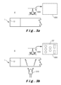
本明細書における「光の拡散(light diffusing)」という用語は、層が透明な光学プレートのように透明ではなくなるように、光拡散層に衝突する光ビームが層の組成によって散乱されるという意味で光の拡散(diffusion)又は散乱(scattering)を意味する。より正確には、本明細書で使用される光拡散層は、人間の目によって又はカメラを使用する直視によってシースルーとなることを許さず、観察者又はカメラの側方に配設される光源による照明のみに依拠する。別の言い方をすれば、本明細書における「光拡散又は散乱層」は、一片の紙の効果と同様に、反射光のみを使用して、図3aに示されるように層が直視では不透明であることを意味する。さらにより正確には、光拡散包装は、包装を通して見ることができないか、又は包装の内側に配置された内管の開口の観察若しくは検出を図示した図3bに示されるように、包装の逆光若しくは側光を使用しなければ、要素若しくは層の存在を直接観察することを可能にしない。本発明では、内管の壁における開口は、外壁によって覆われるため、通常の照明では可視ではなく、したがって「隠し(covert)」機能であると認定されてよく、隠蔽された識別コードを構成する。 The term "light diffusing" in this specification means diffusion or scattering of light in the sense that a light beam impinging on the light diffusing layer is scattered by the composition of the layer so that the layer is no longer transparent like a transparent optical plate. More precisely, a light diffusing layer as used herein does not allow for a see-through appearance by the human eye or by direct viewing using a camera, but relies only on illumination by a light source disposed to the side of the observer or camera. In other words, a "light diffusing or scattering layer" in this specification means that the layer is opaque to direct viewing, as shown in FIG. 3a, using only reflected light, similar to the effect of a piece of paper. Even more precisely, a light diffusing package does not allow for a direct observation of the presence of an element or layer, unless one can see through the package or use backlighting or sidelighting of the package, as shown in FIG. 3b, which illustrates the observation or detection of the opening of an inner tube disposed inside the package. In the present invention, the opening in the wall of the inner tube is not visible in normal lighting because it is covered by the outer wall, and therefore may be qualified as a "covert" feature, constituting a concealed identification code.
ここで、「可視的」又は「検出可能」という用語は、観察され又は検出される部材が特定の波長範囲、例えば可視波長範囲において観察され得ることを意味する。紫外線、可視光又は赤外線波長範囲であり得るいかなる波長領域の制限も存在せず、但し、その波長範囲において内管及び内管上に配置された包装に照明光を提供する光源を使用しなければ本発明の対象物である管の開口を観察し及び検出することができないという限りにおいて、である。本発明の効果は、散乱光による、開口を含む内管の照明に依拠するため、光源の位置は重要ではなく、さらに詳細に説明するように、それは消耗品の周及び/又は軸方向長さの周りの空間4内のいずれの箇所にも配置することができる。
Here, the term "visible" or "detectable" means that the observed or detected member can be observed in a particular wavelength range, for example the visible wavelength range. There is no limitation of any wavelength range, which may be ultraviolet, visible or infrared wavelength range, insofar as the opening of the tube, which is the subject of the present invention, cannot be observed and detected without the use of a light source that provides illumination to the inner tube and the packaging disposed thereon in that wavelength range. Since the effectiveness of the present invention relies on the illumination of the inner tube, including the opening, by scattered light, the location of the light source is not important and can be located anywhere within the
本発明の消耗品の内管における開口群は、以下の2つの効果により視認又は検出が可能になる。
- 外壁の厚さが十分に薄いため、散乱光が内管及び内管を取り囲む包装を通過することができ、
- 包装層が入射光のための拡散器として機能するため、さらに詳細に説明するように、照明光源の角度配向が重要でなくなる。内管は、さらに詳細に説明するように、部分的な透明層又は拡散層であり得る。
The openings in the inner tube of the consumable of the present invention are made visible or detectable by two effects.
the thickness of the outer wall is thin enough to allow scattered light to pass through the inner tube and the packaging surrounding it;
- The angular orientation of the illumination source becomes unimportant as the wrapping layer acts as a diffuser for the incoming light, as will be explained in more detail. The inner tube can be a partially transparent or diffusing layer, as will be explained in more detail.
「内管(inner tube)」という用語は、エアロゾル発生消耗品における管状部材である。内管は、光拡散部材、好ましくは、前述のような包装によって覆われる。内側管状部材は、包装の厚さよりも大きい厚さの紙又はポリマー管であり得る。管状部材は、長手方向において、消耗品のエアロゾル発生部分とフィルタ部分との間に配置され得る。管状部材は、その中を循環する蒸気の温度を冷却する機能を有し得る。管状部材は、中空であってもよく、又は軽いメッシュ材料、不織布材料、ハニカム材料若しくはオープンセル材料などの多孔質充填材で充填されてもよい。管は、長手方向のシームにおいて接着されたロール状の材料シートから形成されてもよく、又は押出成形などの他の技術によって形成されてもよい。充填材を挿入することにより、管状部材内の接触面を増大させて冷却効果を高めることができる。エアロゾル発生材料は、ギャザーシート、ストランド、ストリップ、粉末、スポンジ、発泡体など、任意の適切な形態の再構成タバコなどのタバコベース材料であり得る。内側管状部材は、任意の断面形状又はその管壁の厚さと管の直径との間に任意の比率を有し得る。内管は、不均一な直径を有してもよく、例えば円錐形状を有してもよい。内管は、異なる直径又は異なる外形若しくは内形を有する2つの異なる管状部材などの不連続な部分で作成されてもよい。 The term "inner tube" refers to a tubular member in an aerosol-generating consumable. The inner tube is covered by a light diffusing member, preferably a wrapping as described above. The inner tubular member may be a paper or polymer tube of a thickness greater than the thickness of the wrapping. The tubular member may be located longitudinally between the aerosol-generating portion and the filter portion of the consumable. The tubular member may function to cool the temperature of the vapor circulating therein. The tubular member may be hollow or filled with a porous filler, such as a light mesh material, a nonwoven material, a honeycomb material or an open cell material. The tube may be formed from rolled sheets of material bonded at longitudinal seams or by other techniques such as extrusion. The insertion of a filler material can increase the contact surface within the tubular member to enhance the cooling effect. The aerosol-generating material may be a tobacco-based material, such as reconstituted tobacco in any suitable form, such as gathered sheets, strands, strips, powder, sponge, foam, etc. The inner tubular member may have any cross-sectional shape or any ratio between its wall thickness and the diameter of the tube. The inner tube may have a non-uniform diameter, for example a conical shape. The inner tube may be made of discontinuous sections, such as two different tubular members with different diameters or different external or internal shapes.
管状部材は、包装のように光拡散管であることが好ましいが、必ずしもそうでなくてもよい。さらに詳細に説明するように、開口が回折効果を生み出して、消耗品の部分を横切る照明によって開口を検出することが可能になるため、内管は、光吸収材料で作成されてもよく、又はさらに透明であってもよい。 The tubular member is preferably, but not necessarily, a light diffusing tube, like the packaging. As will be described in more detail below, the inner tube may be made of a light absorbing material or even transparent, since the apertures create a diffraction effect that allows the apertures to be detected by illumination that traverses the portion of the consumable.
本明細書において、「光」という用語は、電磁スペクトルの遠赤外部分の限界である、好ましくは20μmより小さい波長を有する光ビームを含む。 As used herein, the term "light" includes light beams having wavelengths at the far infrared end of the electromagnetic spectrum, preferably less than 20 μm.
本明細書で使用される「穴(hole)」及び「開口(apertures)」という用語は、貫通穴であってもよく、又は管部材料の壁に配置された部分的な穴若しくは段差であってもよい。開口は、ミリメートルサイズの開口であってもよく、又はマイクロメートルサイズの開口であってもよい。 As used herein, the terms "hole" and "apertures" may refer to through holes or partial holes or steps disposed in the wall of the tubing material. The apertures may be millimeter-sized apertures or micrometer-sized apertures.
より詳細には、本発明は、マウスピース部分に取り付けられる消耗品部分を含むエアロゾル発生物品によって達成される。マウスピース部分は、少なくとも1つの内管2を含み、内管表面2b及び外管表面2aを有する。図1及び図2に示されるように、内管2は、少なくとも当該内管の壁における長さにわたって延在し、図2に示されるように、好ましくは当該内管の周に沿って配置される光透過開口201~216の集合体20を含む。
More specifically, the present invention is accomplished by an aerosol generating article that includes a consumable portion attached to a mouthpiece portion. The mouthpiece portion includes at least one
内管2を覆う包装40は、単一の層であってもよく、又は図3に示されるように少なくとも2つの層40a、40bから構成されてもよい。これらの層41、42の1つは、当該内管2だけでなく、エアロゾル発生物品の他の部材を覆い得る。例えば、図1では、包装は、マウスピース1''及び消耗品部分1'の一部を覆う。
The
実施形態では、複数の開口20は、様々な形状及び/又は配向を有し得る。図5は、長手方向の投影が物品1の中心軸Zと交差しない貫通開口221~228を含む内管40の実施形態を示している。
In embodiments, the
実施形態では、外側包装40は、内管2の外側表面2aと接触する内側表面40bを有する。変形例において、少なくとも1つの追加の層が内管2と包装40との間に配置されてもよい。そのような追加の層は、接着剤層、シーム層、接合層又はスペーサ層であり得る。図示されていないそのような追加の層は、入射光に対して少なくとも部分的に透明であり、光拡散層であってもよく、光吸収特性を有する層であってもよい。
In an embodiment, the outer wrapping 40 has an
有利な実施形態では、開口は、その上で入射光を回折する非常に小さい開口であってもよく、例えば2mm~50μm、好ましくは1mm~65μm、最も好ましくは500μm~100μmに含まれる最大断面寸法又は直径を有する開口であってもよい。開口は、レーザによって製造されてもよい。開口の深さは、全厚さを通して行われない場合、典型的には100~800μmであり得るが、100μmより小さくてもよい。 In an advantageous embodiment, the aperture may be a very small aperture over which the incident light is diffracted, for example an aperture having a maximum cross-sectional dimension or diameter comprised between 2 mm and 50 μm, preferably between 1 mm and 65 μm, most preferably between 500 μm and 100 μm. The aperture may be manufactured by means of a laser. The depth of the aperture, if not carried out through the entire thickness, may typically be between 100 and 800 μm, but may also be less than 100 μm.
内側管状部材2は、包装の厚さよりも大きい厚さの紙又はポリマー管であり得る。管状部材は、消耗品のエアロゾル発生部分とフィルタ部分との間に配置され得る。管状部材は、その中を循環する蒸気の温度を冷却する機能を有し得る。管状部材は、中空であってもよく、又は軽いメッシュ材料、不織布材料、ハニカム材料若しくはオープンセル材料などの多孔質充填材で充填されてもよい。充填材を挿入することにより、管状部材内の接触面を増大させて冷却効果を高めることができる。エアロゾル発生材料は、ギャザーシート、ストランド、ストリップ、粉末、スポンジ又は発泡体など、任意の適切な形態の再構成タバコなどのタバコベース材料であり得る。
The inner
内管2は、光散乱性材料で作成される包装40の内側に配置される。好ましくは、包装は、紙又は厚紙で作成される。
The
一実施形態では、上記内管2は、光散乱性材料で作成される。変形例では、内管2は、光学的不透明材料又は部分的な光透過を有する材料で作成されてもよい。
In one embodiment, the
一実施形態では、内管2及び包装40は、異なる材料で作成され、且つ異なる光散乱特性を有する。
In one embodiment, the
一実施形態では、管2及び/又は包装40は、少なくとも部分的に紙で作成され、且つ好ましくは異なる厚さを有する。
In one embodiment, the
包装40及び内管2は、以下の典型的な寸法を有し得る。物品の外周は、16mm~25mm、好ましくは17mm~22mmに含まれ得る。内管の内周は、10mm~20mmであり得る。内管の厚さは、0.2~1.5mm、好ましくは0.3~1mmであってよく、包装の厚さは、50~250ミクロン、好ましくは60~120ミクロンであってよい。それらは、紙で作成され得る。包装のための紙のグラム数は、約15~80g/m2であってよい。内管のための紙のグラム数は、約50~180g/m2であってよい。
The
開口は、円形状の開口であってもよく、矩形状の開口などの他の形状を有してもよい。開口アレイ20、20'、20''の開口は、少なくとも部分的に円錐形の開口であってもよい。
The apertures may be circular apertures or may have other shapes, such as rectangular apertures. The apertures of the
図6に示される実施形態では、内管2は、貫通開口201'~211'を有する少なくとも1つの光吸収層30を含む。そのような吸収層30の開口は、光透過開口201~216、220~216の集合体20と位置合わせされる。吸収層30の開口201'~211'は、好ましくは、貫通開口である。吸収層30の開口201'~211'は、内管2の開口201~216、220~216よりも広くても又は小さくてもよい。
In the embodiment shown in FIG. 6, the
吸収層30は、内管に配置される別個の層であってもよく、或いはインク層などの堆積層又は完全に不透明であるか、又は上記開口の存在、及び/若しくは形状、及び/若しくは配置を検出するために使用される光の波長に対して部分的な透過を有する任意の層のいずれかであってもよい。
The absorbing
一実施形態では、内管2は、少なくとも2つの層(図示せず)で作成される。内管2の少なくとも1つの層は、光拡散層であり得る。
In one embodiment, the
一実施形態では、上記包装及び/又は内管層の少なくとも1つの少なくとも一部は、ポリ乳酸(PLA)又は厚紙で作成される。 In one embodiment, at least a portion of at least one of the packaging and/or inner tube layers is made of polylactic acid (PLA) or cardboard.
有利な配置では、内管2は、例えば、UV光の照射時に発光する蛍光基材を含んでもよい。これにより、そのような実施例における開口201~216、220~216が蛍光基材を含まないことで、検出器に向けられる透過光ビームにおける大規模な差を実現することが可能になる。そのような場合、開口201~216、220~216によって提供される光ビームは、可視性がはるかに低くなるかもしれず、その周囲がはるかに多くの光強度を提供するため、その存在を検出することを可能にする。例えば、紫外線光源で、物品1を通して内管2を照射することができ、可視領域において2次光ビームを提供することができる。開口は、201~216、220~216である。そのような実施形態(図示せず)では、包装40によって提供される散乱光の強度分布における暗い領域により検出され得る。
In an advantageous arrangement, the
図16a、図16b及び図17a~図17cに示される実施形態では、開口201~216、220~216の集合体20、20'、20''は、上記内管の周上に配置される少なくともN個の平行なアレイに従って配置され、Nは2以上である。
In the embodiment shown in Figures 16a, 16b and 17a-17c, the
一実施形態では、上記N個のアレイの少なくとも2つは、開口201~216、220~216間にM個の異なる離隔量(separation)を有し、Mは2以上である。例えば、図16bは、4列の開口が、2つの異なる分離距離d1、d2に従って配置され得る複数の開口を含む配置を示しており、ここで、Nは4に等しく、Mは2に等しい。 In one embodiment, at least two of the N arrays have M different separations between the apertures 201-216, 220-216, where M is greater than or equal to 2. For example, FIG. 16b shows an arrangement in which four rows of apertures include a plurality of apertures that may be arranged according to two different separation distances d1, d2, where N is equal to 4 and M is equal to 2.
図17a~図17cに示される有利な実施形態では、上記N個のアレイの少なくとも2つは、当該少なくとも2つのアレイによって形成される平面に直交する同じ仮想線上に位置合わせされない開口201~216、220~216を含む。不整列(unalignment)のレベルは、所定の分離距離の割合fとして識別され得る開口のアレイ間の位相を定義する。例えば、図17b及び図17cでは、位相は、開口の第1の列の開口201~216、220~216の分離距離d1の1/3に等しい。 In an advantageous embodiment shown in Figures 17a-c, at least two of the N arrays include apertures 201-216, 220-216 that are not aligned on the same imaginary line perpendicular to the plane formed by the at least two arrays. The level of misalignment defines a phase between the arrays of apertures that can be identified as a percentage f of a predetermined separation distance. For example, in Figures 17b and 17c, the phase is equal to 1/3 of the separation distance d1 of the apertures 201-216, 220-216 of the first row of apertures.
図示されていない実施形態において、開口201~216、220~216は、例えば、正弦曲線又はヘリコイド曲線など、内管の周上に画定される曲線に沿って配置されてもよい。 In an embodiment not shown, the openings 201-216, 220-216 may be arranged along a curve defined on the circumference of the inner tube, such as, for example, a sinusoidal or helicoidal curve.
有利な実施形態では、図7に示されるように、開口20、20'、20''のアレイは、異なるタイプの開口を含み得る。例えば、第1及び第2の複数の開口20、20'は、円形断面を有する開口であってもよく、第3の複数の開口20''は、矩形断面又は他の多角形断面を有する開口であってもよい。
In an advantageous embodiment, as shown in FIG. 7, the array of
第2の態様では、本発明は、エアロゾル発生装置100と、説明される通りのエアロゾル発生物品1及び上記エアロゾル発生装置100を含むエアロゾル発生システムとによって達成される。エアロゾル発生装置100は、外側本体部に配置された、電源部分(図示せず)と、外側本体部においてアクセス可能である開口を有し、且つ説明されるようなエアロゾル発生物品1を受けるように構成された空洞102とを含む。図18は、上記エアロゾル発生装置100と、上記エアロゾル発生装置100内へのその挿入位置にある上記エアロゾル発生物品とを含む、本発明の典型的なエアロゾル発生システムに関する部分図を示している。
In a second aspect, the present invention is achieved by an
エアロゾル発生装置100は、少なくとも1つの光ビーム320を提供する少なくとも1つの光学的光源310を含む少なくとも1つの照明システム300と、空洞102の好ましくは対向し合う側に配置される検出システム400とを含む。
The
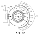
図10及び図12は、照明システム300と、開口201~216、220~216の集合体20、20'、20''による透過光によって提供される情報を読み取るための光検出器401~414のアレイ400とを含むエアロゾル発生装置100の構成を示す。照明システム300及び検出器システム400は、装置100内の様々な場所に配置されてよい。例えば、図10及び図12は、少なくとも1つの発光システム300が検出器システム400の反対側に配置される好ましい構成を示す。
10 and 12 show a configuration of an
図12は、光340が包装40内に進んでいることを示している。その光の一部は、開口201~216、220~216によって透過し、別の一部は、内管2の、当該開口間にある他の壁部によって透過する。
Figure 12 shows that light 340 travels into the
有利な実施形態では、検出システム400の上記検出器402~414の少なくとも1つは、検出器401~414のアレイ上の投影光ビーム351~353、351'~354'の最大直径より小さい横方向寸法を有する。
In an advantageous embodiment, at least one of the detectors 402-414 of the
照明システム300は、発光体などの直接光源であり得る少なくとも1つの照明源310を含む。光源310は、光導波路の先端部又は発光要素から離れて配置されたエネルギー源若しくは光源によって照明される蛍光材料を含む光学要素の先端など、光学要素の先端部(ここでは図示せず)であってもよい。発光システム300は、好ましくは、任意の紫外線、可視光若しくは赤外線光源又はそのような光源の組み合わせであり得る光源310を含む。エアロゾル発生装置100において利用可能なスペースは、非常に限られるため、光源310は、好ましくは、LED、SLED又は半導体光源などの半導体光源である。
The
変形例では、本発明における光源310は、赤外線光源であってもよい。光源は、エアロゾル発生装置100の加熱器によって生成されてもよく、又は別個の光源であってもよい。
In a variant, the
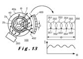
図11は、内管2の貫通開口201~216、220~228の照明及び光透過並びに内管及び内管に配置された包装を通過する複数の光ビームの詳細図を示している。図11は、包装2から検出器アレイに送達される複数の光ビーム350の光コーンC1~C3の断面をさらに示している。出射光コーンC1~C3は、発散光コーンであるため、検出器システム400における透過光ビーム350の断面351~353、351'~353'は、包装の外面40aに対する検出器システム400の距離に依存する。図11は、検出器アレイの前に画定された仮想画像平面402における強度変化I(θ)を示している。仮想画像平面は、平面又は曲面であってよく、後者が図13の実施形態において示されている。好ましい実施形態では、上記強度変化I(θ)の最大強度は、開口201~216、220~228を透過した光ビームによって提供され、最小強度は、内管2及び包装の壁を通過した散乱光によって提供される。仮想画像平面402は、検出器アレイの感光面において画定され得るが、検出器アレイ401~414の前に距離を置いて配置されてもよい。
11 shows a detailed view of the illumination and light transmission of the through openings 201-216, 220-228 of the
実施形態では、遮断された光強度I(θ)のコントラストを改善し、また異なる透過光ビーム間のクロストークを低減するために、不透明材料で作成されたピンホール又は視野角制限開口のアレイが検出器アレイの前に配置されてもよい。そのような実施形態では、図示されていないが、仮想画像平面402は、ピンホール又は視野角制限開口のアレイの平面である。
In an embodiment, an array of pinholes or field-angle limiting apertures made of an opaque material may be placed in front of the detector array to improve the contrast of the blocked light intensity I(θ) and to reduce crosstalk between different transmitted light beams. In such an embodiment, although not shown, the
有利な実施形態では、図11に示されるものに対して相補的な光強度分布(図示せず)が可能である。例えば、内管2は、例えば、UV光の照射時に発光する蛍光基材を含み得る。そのような場合、開口201~216、220~228によって提供される光ビームは、可視性がはるかに低いため、包装によって散乱された実質的に均一な光ビーム上に与えられた暗い領域としてそれらの存在を検出することを可能にし得る。そのような実施形態の開口は、次いで、強度分布における暗い領域によって検出される。この効果は、検出器システム400の前に配置された光学フィルタを使用することによって大幅に強化され得る。例えば、UVバンドパスフィルタが使用されてもよく、この場合、開口によって提供される光のみが検出されて、大きいコントラストを有する強度信号が提供される。検出器401~414の前に可視光吸収フィルタが使用されてもよい。そのような場合、開口201~216、220~228は、検出器401~414に光を透過しないが、包装により検出器システム400に向かって散乱された可視光によって提供される、検出された強度信号における落ち込み(dips)によって検出可能である。
In advantageous embodiments, a light intensity distribution (not shown) complementary to that shown in FIG. 11 is possible. For example, the
検出器アレイ400に衝突する光ビームの形状及びコントラスト並びに強度の分解能は、所望の光学効果の機能において適合され得る。
The shape and contrast as well as the intensity resolution of the light beam impinging on the
測定される光強度I(θ)が、以下のパラメータの1つ又はいくつかを適合させることによって最適化されてもよい。
-包装40と検出器アレイとの間の最小の距離を使用すること、
-角度位置θに応じた光の変動を正確に特性化する目的で、小さい距離だけ離隔される多数のセンサを使用すること(例えば、湾曲したCCD又は湾曲した検出器アレイであり得る、リニアCCDを使用すること)、
-検出器アレイ401~402の平面内の正確な位置において光を測定する目的で、非常に小さい検出領域Dを伴うセンサ要素群を使用すること(図13)、
-例えば蛍光若しくは燐光材料又は検出器アレイに配置された色若しくは干渉フィルタによって組み合わされ得る特定の光吸収特性を有する材料を使用することにより、光信号のコントラストを高める専用の材料を使用すること。
The measured light intensity I(θ) may be optimized by adapting one or several of the following parameters:
- using a minimum distance between the
- using multiple sensors spaced a small distance apart in order to accurately characterize the variation of light as a function of angular position θ (for example using a linear CCD, which may be a curved CCD or a curved detector array);
- using a group of sensor elements with a very small detection area D in order to measure light at a precise position in the plane of the detector array 401-402 (Figure 13);
- The use of dedicated materials to enhance the contrast of the optical signal, for example by using fluorescent or phosphorescent materials or materials with specific light absorption properties that can be combined by color or interference filters arranged on the detector array.
有利な構成において、検出器アレイ401~415によって遮断される光ビーム351~353、351'~354'の幅が、包装40上でのそれらの射出場所に応じて適合されてもよい。例えば、穴又は開口201~216、220~216のサイズ、検出器アレイに対する間隔の距離を調整するか、又は内管の部分吸収材料を用いるか、又は特定の光散乱特性を有する紙を使用することによって、開口201~216により提供される投影される光ビーム351~353の断面が、開口201~216、220~216を透過しない散乱される光ビーム351'~354'の断面とは異なってもよい。断面サイズにおける差は、少なくとも2倍以上、さらに5倍以上であってもよい。さらに説明する図13は、検出器アレイシステム400によって遮断される光ビーム351~355、351'~355'の断面が重なり合う別の例を示している。
In an advantageous configuration, the width of the light beams 351-353, 351'-354' blocked by the detector arrays 401-415 may be adapted depending on their emission location on the
センサ401~414の数が少ない(例えば4つの個別のセンサ401~415を使用する)場合、開口によって提供される光ビーム351~356の測定される光強度と、内管2の残りの表面によって提供される光351'~355'との間の差を最大化するために、光検出面に沿ってそれらセンサが最適な位置に実装されてもよい。
When the number of sensors 401-414 is small (e.g., using four individual sensors 401-415), they may be mounted in optimal positions along the light detection surface to maximize the difference between the measured light intensity of the light beams 351-356 provided by the apertures and the light 351'-355' provided by the remaining surface of the
ここで、検出器401~414のいくつかの例示的な配置について説明する。 We now describe some example arrangements of detectors 401-414.
例えば、図14が示している状況において、dは、検出器アレイの光感知面と交差している光の2つの連続する最大値間の距離である。2つの光センサのみが使用される場合、検出器平面におけるそれぞれの位置D1、D2は、D2-D1=d/2となるようにする必要がある。しかしながら、偶然にもセンサの位置が明るい領域と暗い領域との境界にある場合、両方のセンサ間の強度差は、小さくなる。これを回避するために、追加のセンサが使用され得る。 For example, in the situation shown in Figure 14, d is the distance between two successive maxima of light intersecting the light-sensitive surface of the detector array. If only two light sensors are used, their respective positions D1, D2 in the detector plane should be such that D2-D1=d/2. However, if by chance the position of a sensor is on the border between a light and a dark area, the intensity difference between both sensors will be small. To avoid this, an additional sensor can be used.
4つのセンサが使用される場合、第3及び第4のセンサの位置であるD3及びD4の位置は、D3-D2=d/4及びD4-D3=d/2となるようにする必要がある。 If four sensors are used, the positions of the third and fourth sensors, D3 and D4, should be such that D3-D2=d/4 and D4-D3=d/2.
6つ以上のセンサを最適に配置する場合にも同じ論理が適用される。 The same logic applies when optimally placing six or more sensors.
しかしながら、センサの数を3つに減らすことが可能である。最適に配置されると、1周期にわたる強度変化を検出し、穴開け又は構造化パターンの存在を確認することが可能になる。この場合、3つのセンサは、D2-D1=d/2及びD3-D2=d/4となるように配置される。I(x)を位置xの関数における光強度とし、あるいはI(θ)が角度の関数における光強度を表すとすると(図13)、Max(I(D2)-I(D1)、I(D3)-I(D2))>Tであるときに肯定的な検出がなされ、ここでTは、検出装置(即ちエアロゾル発生装置)にハードコーディングされるか、又は他のローカルな若しくはリモートの入力に基づいて検出装置によって生成される閾値である。 However, it is possible to reduce the number of sensors to three. When optimally positioned, it is possible to detect the intensity change over one period and confirm the presence of a perforation or structured pattern. In this case, the three sensors are positioned such that D2-D1=d/2 and D3-D2=d/4. If I(x) is the light intensity as a function of position x, or I(θ) is the light intensity as a function of angle (FIG. 13), then a positive detection occurs when Max(I(D2)-I(D1), I(D3)-I(D2))>T, where T is a threshold value that is hard-coded into the detection device (i.e., the aerosol generating device) or is generated by the detection device based on other local or remote inputs.
また、3つのセンサのグループを2つ使用することも可能であり、各グループは、距離d及びd'において変調を検出するようにそれぞれ最適化され得る。この場合、第1のグループは、D2-D1=d/2及びD3-D2=d/4となるように、第2のグループは、D2'-D1'=d'/2及びD3'-D2'=d'/4となるように距離が設定される。 It is also possible to use two groups of three sensors, each optimized to detect modulation at distances d and d'. In this case, the first group would be set to distances D2-D1=d/2 and D3-D2=d/4, and the second group would be set to distances D2'-D1'=d'/2 and D3'-D2'=d'/4.
また、多数のセンサ401~414、例えば10個よりも多く、20個よりも多くのセンサが使用されてもよい。明るい領域及び暗い領域の数の少なくとも2倍という多数のセンサを使用することにより、信号処理アプローチを使用して信頼性の高い検出を行うことができる。I(Xn)が、検出器平面で画定された均一にサンプリングされる位置Xnにおいて測定される光強度である場合、識別コード又は信号の検出のために周波数変換Fを使用することができる。Fは、任意の変換されたドメイン、特にフーリエ又はDCT(離散コサイン変換)のような周波数変換であり得る。周波数変換信号Fの最大値は、明るい領域の間隔に対応する周波数1/dに位置する。したがって、有利な検出方法は、残余の周波数変換値に対するF(1/d)の信号対雑音比を測定して、予め定義される閾値と比較することを含む。
Also, a large number of sensors 401-414 may be used, for example more than 10, more than 20. By using a large number of sensors, at least twice the number of bright and dark areas, a signal processing approach can be used for reliable detection. If I(Xn) is the light intensity measured at a uniformly sampled position Xn defined in the detector plane, a frequency transformation F can be used for the detection of the identification code or signal. F can be any transformed domain, in particular a frequency transformation such as Fourier or DCT (Discrete Cosine Transform). The maximum of the frequency transformed signal F is located at a
変形例において、相補的な光学構成に対して同じ原理が適用されてもよく、その場合、開口によって提供される光ビームは周囲の散乱光よりも低い光強度を有する。 In a variant, the same principle may be applied to a complementary optical configuration, in which the light beam provided by the aperture has a lower light intensity than the surrounding scattered light.
有利な実施形態において、検出器アレイが異なる形状を有する複数の検出器を含んでもよく、検出器アレイが湾曲した基材上に配置されてもよい。 In advantageous embodiments, the detector array may include multiple detectors having different shapes, and the detector array may be disposed on a curved substrate.
本発明の作用は、散乱光による内管2の照明に依拠することから、光源310の位置は重要ではなく、さらに詳細に述べるように、消耗品の周上のいずれの箇所にも配置することができる。
Because the operation of the present invention relies on illumination of the
変形例では、図13に示されるように、光源は、検出器システム400に対してある角度をもって配置されてもよい。
In a variant, the light source may be positioned at an angle relative to the
一実施形態では、これらの検出器の空間光受容角として画定される検出器402~415の角度開口は、2つよりも多く、好ましくは5つよりも多く、より好ましくは10個よりも多く、さらにより好ましくは20個よりも多くの開口201~216、220~228から、及び/又は開口201~216、220~228の2つよりも多くのアレイ20、20'、20''からの光が上記光学読取りシステム400によって検出可能であるように選択される。
In one embodiment, the angular apertures of the detectors 402-415, defined as the spatial light acceptance angles of these detectors, are selected such that light from more than two, preferably more than five, more preferably more than ten, and even more preferably more than twenty apertures 201-216, 220-228 and/or from more than two
上記アプローチのさらなる複雑な態様では、透過した強度パターンが消耗品のシリアル化又は識別のためにさらに使用され得る消耗品のエンコードを表すことになるように、穿孔(perforations)が不均一な間隔を有する。この複雑な態様では、このエンコードを正しくサンプリングするために、より多くのセンサが必要とされる。 In a more complex version of the above approach, the perforations are non-uniformly spaced such that the transmitted intensity pattern represents an encoding of the consumable that can be further used for serialization or identification of the consumable. In this more complex version, more sensors are required to properly sample this encoding.
開口201~216、220~228によって提供される符号化された情報のいくつかの例をここで説明する。 Some examples of the encoded information provided by apertures 201-216, 220-228 are now described.
図16aは、4ラインのコードを使用して16個の異なる値を符号化することを可能にする2値符号化の例を示す。図16bは、距離d又は2×dだけ離れた穴のラインを使用する(例えば、上述のように3つのセンサの2つのグループを使用する)3値符号化を示す。これにより、34=81個の異なる値を符号化することが可能になる。より一般的には、穴のラインがn1個あり、各ラインがn2個の異なる間隔を有する場合、コードの個数は、(n2+1)n1に等しくなる。 Figure 16a shows an example of a binary coding that makes it possible to code 16 different values using a four-line code. Figure 16b shows a ternary coding that uses lines of holes spaced a distance d or 2xd apart (e.g. using two groups of three sensors as described above). This makes it possible to code 3 4 = 81 different values. More generally, if there are n1 lines of holes, each with n2 different spacings, the number of codes is equal to (n2 + 1) n1 .
一実施形態では、検出器システム400は、上記光ビームの空間周波数及び/又は少なくとも1つの光学位相(η)を検出するように構成される。
In one embodiment, the
一実施形態では、上記検出器のアレイは、上記空洞軸に対して画定される異なる角度分離量を有する少なくとも3つの検出器を含む。 In one embodiment, the detector array includes at least three detectors having different angular separations defined relative to the cavity axis.
例えば、2Dセンサアレイを使用することにより、各ラインにセンサのいくつかのグループを追加することによって開口201~216、220~228の2つのライン間の位相を検出することも可能であり得る。例えば、ケース(a)において2つのラインの位相は0に等しく、ケース(b)においてはd/3であり、ケース(c)においては2d/3である。これにより、3つの異なる値を符号化することが可能になる。十分な数のセンサを使用すれば、任意の数の位相に一般化することができる。 For example, by using a 2D sensor array, it may also be possible to detect the phase between two lines of apertures 201-216, 220-228 by adding several groups of sensors to each line. For example, in case (a) the phase of the two lines is equal to 0, in case (b) it is d/3 and in case (c) it is 2d/3. This makes it possible to encode three different values. It can be generalized to any number of phases if a sufficient number of sensors is used.
図17a~図17cに示されるように、異なる間隔値dと、異なる位相値との両方の変化を組み合わせることにより、組み合わせの数をさらに増大させることが可能である。 As shown in Figures 17a to 17c, it is possible to further increase the number of combinations by combining both different spacing values d and different phase values.
上記で説明した開口201~216、220~228によって引き起こされるものと同様の強度変化は、以下のような代替プロセスによっても生成され得ることをここで強調しておく。
-穴を伴ってベタ塗りされる複数色の印刷、色の中に開口あり。
-電子透かしのような技術、即ち紙の厚さを変動させるアプローチ。
It is emphasized here that intensity variations similar to those caused by the apertures 201-216, 220-228 described above can also be produced by alternative processes as follows.
- Multi-colour printing with solid colours and holes, with openings in the colours.
- Techniques such as digital watermarking, ie approaches that vary the thickness of the paper.
さらに、軸方向にシフトされ得る較正センサ400'が図18に示されている。較正センサ400'の読取りは、較正信号として機能し、したがって印刷及び電子透かしによって生成されるものなどの代替的な符号化を検出することを可能にする。 Furthermore, a calibration sensor 400' that can be shifted axially is shown in FIG. 18. The reading of the calibration sensor 400' serves as a calibration signal, thus making it possible to detect alternative encodings such as those produced by printing and digital watermarks.
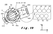
図19に示される有利な実施形態では、内管2の開口20、20'、20''が包装40の一部を撮像することで検出されてもよい。包装40の外面40aに伝達される光ビームは、異なる照明領域41~44、41'~43'を提供する。撮像システムの所望の開口Ωに応じて、撮像レンズ450を選択することができる。レンズ450の焦点距離及び画像検出器のサイズは、画像平面600上で撮像されなければならない包装の外面40a上の領域を左右する。レンズ450の焦点距離の選択は、画像平面600における所望の解像度にも依存する。焦点距離は、3mm未満であり得る。図19に示される撮像装置400は、4×4×4mm未満の体積を有する非常に小さい撮像装置であってもよい。実施形態では、そのような非常に小さい撮像装置のアレイが装置100の空洞102に配置され得る。変形例では、凹面鏡が撮像レンズ450の代替として使用されてもよい。これにより、より大きい焦点距離を提供することを可能にするため、視野Ωがより小さくなるが、一方で解像度がより高くなる。光ビームの強度の測定ではなく、撮像システムを使用することは、内管2の表面のうちの少なくとも1つに標識(sign)などがプレスされる構造の場合に、特に有利であり得る。
In an advantageous embodiment shown in FIG. 19, the
Claims (15)
前記マウスピース部分(1'')は、少なくとも1つの内管(2)と包装(40)とを含み、前記内管は、前記包装(40)の内側に配置され、
前記マウスピース部分(1'')は、前記内管(2)の周及び/又は長手方向に沿って配置される、少なくとも前記内管(2)の壁における長さにわたって延在する複数(20、20'、20'')の光透過開口(201~216、220~228)を含む、符号化されたデータを表す機械可読パターンを含む、
エアロゾル発生物品(1)。 An aerosol-generating article (1) comprising a consumable part (1′) attached to a mouthpiece part (1″),
said mouthpiece portion (1'') comprises at least one inner tube (2) and a packaging (40), said inner tube being arranged inside said packaging (40);
the mouthpiece portion (1'') includes a machine-readable pattern representing encoded data, the machine-readable pattern including a plurality (20, 20', 20'') of light-transmitting apertures (201-216, 220-228) disposed circumferentially and/or longitudinally of the inner tube (2) and extending at least the length of the wall of the inner tube (2);
An aerosol-generating article (1).
前記エアロゾル発生装置(100)は、前記空洞(102)の側方に配置された少なくとも1つの光学的光源(310)を含む少なくとも1つの照明システム(300)をさらに含み、
前記エアロゾル発生装置(100)は、前記光透過開口(201~216、220~228)のアレイ(20)を透過した透過光(350)によって提供される情報を読み取るための、少なくとも2つの検出器(401~415)を含む光学読取りシステム(400)をさらに含む、
エアロゾル発生システム。 An aerosol generation system comprising an aerosol-generating article (1) according to any one of claims 1 to 10, and an aerosol generating device (100) comprising a power source portion and a cavity (102) arranged in an outer body portion (110), said cavity (102) defining a cavity axis, having an accessible opening in said outer body portion and configured to receive said aerosol-generating article (1),
The aerosol generating device (100) further comprises at least one illumination system (300) including at least one optical light source (310) arranged laterally of the cavity (102),
The aerosol generating device (100) further comprises an optical reading system (400) including at least two detectors (401-415) for reading information provided by the transmitted light (350) transmitted through the array (20) of light-transmitting apertures (201-216, 220-228),
Aerosol generation systems.
Applications Claiming Priority (3)
| Application Number | Priority Date | Filing Date | Title |
|---|---|---|---|
| EP20179616.6 | 2020-06-12 | ||
| EP20179616 | 2020-06-12 | ||
| PCT/EP2021/064721 WO2021249835A1 (en) | 2020-06-12 | 2021-06-01 | Aerosol-generating article and device for identifying a smoking article |
Publications (3)
| Publication Number | Publication Date |
|---|---|
| JP2023528796A JP2023528796A (en) | 2023-07-06 |
| JPWO2021249835A5 JPWO2021249835A5 (en) | 2024-04-17 |
| JP7635263B2 true JP7635263B2 (en) | 2025-02-25 |
Family
ID=71094115
Family Applications (1)
| Application Number | Title | Priority Date | Filing Date |
|---|---|---|---|
| JP2022572795A Active JP7635263B2 (en) | 2020-06-12 | 2021-06-01 | Apparatus for identifying aerosol-generating articles and smoking articles |
Country Status (7)
| Country | Link |
|---|---|
| US (1) | US12465090B2 (en) |
| EP (1) | EP4164423B1 (en) |
| JP (1) | JP7635263B2 (en) |
| KR (1) | KR20230022999A (en) |
| CN (1) | CN115666282B (en) |
| PL (1) | PL4164423T3 (en) |
| WO (1) | WO2021249835A1 (en) |
Families Citing this family (2)
| Publication number | Priority date | Publication date | Assignee | Title |
|---|---|---|---|---|
| US20240122258A1 (en) * | 2021-02-23 | 2024-04-18 | Jt International Sa | An Electrically Powered Smoking Device Including an Optical Sensing System for Identifying Indicium of Smoking Articles |
| JP7792435B2 (en) * | 2021-12-28 | 2025-12-25 | 日本たばこ産業株式会社 | Non-burning flavor inhaler |
Citations (8)
| Publication number | Priority date | Publication date | Assignee | Title |
|---|---|---|---|---|
| JP2012513750A (en) | 2008-12-24 | 2012-06-21 | フィリップ・モーリス・プロダクツ・ソシエテ・アノニム | Articles having identification information for use in an electrically heated smoking system |
| JP2013534163A (en) | 2010-08-19 | 2013-09-02 | サノフィ−アベンティス・ドイチュラント・ゲゼルシャフト・ミット・ベシュレンクテル・ハフツング | Method and system for determining information relating to a drug reservoir using an electronic sensor |
| JP2014530736A (en) | 2011-10-28 | 2014-11-20 | コーニンクレッカ フィリップス エヌ ヴェ | Analysis and control of aerosol flow |
| US20160325055A1 (en) | 2015-05-08 | 2016-11-10 | Lunatech, Llc | Device To Deliver Cannabidiol And Associated Compounds To Promote Health |
| JP2017501682A (en) | 2013-12-03 | 2017-01-19 | フィリップ・モーリス・プロダクツ・ソシエテ・アノニム | An aerosol generating article incorporating a taggant and an electrically operated system |
| JP2019506894A (en) | 2015-12-28 | 2019-03-14 | アール・エイ・アイ・ストラテジック・ホールディングス・インコーポレイテッド | Aerosol delivery device including housing and coupler |
| WO2019185747A1 (en) | 2018-03-29 | 2019-10-03 | Nicoventures Trading Limited | Apparatus for generating aerosol from an aerosolisable medium, an article of aerosolisable medium and a method of operating an aerosol generating apparatus |
| WO2020109404A1 (en) | 2018-11-27 | 2020-06-04 | Philip Morris Products S.A. | Sensor for device aerosol-generating system |
Family Cites Families (8)
| Publication number | Priority date | Publication date | Assignee | Title |
|---|---|---|---|---|
| US4766911A (en) * | 1986-06-23 | 1988-08-30 | R. J. Reynolds Tobacco Company | Method for tracing smoking articles |
| GB2481014A (en) | 2010-06-07 | 2011-12-14 | British American Tobacco Co | Wrapper for a smoking article |
| US20150128968A1 (en) * | 2013-11-11 | 2015-05-14 | R.J. Reynolds Tobacco Company | Mouthpiece for smoking article |
| US20150128969A1 (en) | 2013-11-11 | 2015-05-14 | R.J. Reynolds Tobacco Company | Mouthpiece for smoking article |
| EP3270718B1 (en) * | 2015-03-17 | 2019-12-18 | Philip Morris Products S.a.s. | Smoking article assembly with a fitted tube |
| EP3120717A1 (en) * | 2015-07-24 | 2017-01-25 | JT International SA | Smoking article |
| GB201607474D0 (en) * | 2016-04-29 | 2016-06-15 | British American Tobacco Co | Article, apparatus and method of heating a smokable material |
| KR102330299B1 (en) * | 2018-11-23 | 2021-11-24 | 주식회사 케이티앤지 | A cigarette including an outer wrapper |
-
2021
- 2021-06-01 JP JP2022572795A patent/JP7635263B2/en active Active
- 2021-06-01 WO PCT/EP2021/064721 patent/WO2021249835A1/en not_active Ceased
- 2021-06-01 EP EP21730190.2A patent/EP4164423B1/en active Active
- 2021-06-01 CN CN202180040941.6A patent/CN115666282B/en active Active
- 2021-06-01 US US18/009,535 patent/US12465090B2/en active Active
- 2021-06-01 KR KR1020237001002A patent/KR20230022999A/en active Pending
- 2021-06-01 PL PL21730190.2T patent/PL4164423T3/en unknown
Patent Citations (8)
| Publication number | Priority date | Publication date | Assignee | Title |
|---|---|---|---|---|
| JP2012513750A (en) | 2008-12-24 | 2012-06-21 | フィリップ・モーリス・プロダクツ・ソシエテ・アノニム | Articles having identification information for use in an electrically heated smoking system |
| JP2013534163A (en) | 2010-08-19 | 2013-09-02 | サノフィ−アベンティス・ドイチュラント・ゲゼルシャフト・ミット・ベシュレンクテル・ハフツング | Method and system for determining information relating to a drug reservoir using an electronic sensor |
| JP2014530736A (en) | 2011-10-28 | 2014-11-20 | コーニンクレッカ フィリップス エヌ ヴェ | Analysis and control of aerosol flow |
| JP2017501682A (en) | 2013-12-03 | 2017-01-19 | フィリップ・モーリス・プロダクツ・ソシエテ・アノニム | An aerosol generating article incorporating a taggant and an electrically operated system |
| US20160325055A1 (en) | 2015-05-08 | 2016-11-10 | Lunatech, Llc | Device To Deliver Cannabidiol And Associated Compounds To Promote Health |
| JP2019506894A (en) | 2015-12-28 | 2019-03-14 | アール・エイ・アイ・ストラテジック・ホールディングス・インコーポレイテッド | Aerosol delivery device including housing and coupler |
| WO2019185747A1 (en) | 2018-03-29 | 2019-10-03 | Nicoventures Trading Limited | Apparatus for generating aerosol from an aerosolisable medium, an article of aerosolisable medium and a method of operating an aerosol generating apparatus |
| WO2020109404A1 (en) | 2018-11-27 | 2020-06-04 | Philip Morris Products S.A. | Sensor for device aerosol-generating system |
Also Published As
| Publication number | Publication date |
|---|---|
| CN115666282A (en) | 2023-01-31 |
| JP2023528796A (en) | 2023-07-06 |
| EP4164423B1 (en) | 2024-10-16 |
| CN115666282B (en) | 2025-12-30 |
| US20230346038A1 (en) | 2023-11-02 |
| KR20230022999A (en) | 2023-02-16 |
| US12465090B2 (en) | 2025-11-11 |
| EP4164423C0 (en) | 2024-10-16 |
| PL4164423T3 (en) | 2025-02-10 |
| WO2021249835A1 (en) | 2021-12-16 |
| EP4164423A1 (en) | 2023-04-19 |
Similar Documents
| Publication | Publication Date | Title |
|---|---|---|
| JP7695930B2 (en) | Electrically Operated Smoking System Including an Optical Projection System for Identifying Smoking Articles Carrying Indicia - Patent application | |
| JP7635263B2 (en) | Apparatus for identifying aerosol-generating articles and smoking articles | |
| JP7734702B2 (en) | Method and system for identifying aerosol-generating articles | |
| JP7693665B2 (en) | A non-combustion heated aerosol generating device including means for authenticating an aerosol-generating article by internal irradiation thereof | |
| US20230255259A1 (en) | Smoking Article for Aerosol Generation Device Comprising Information Code | |
| CN115666281B (en) | Method and system for identifying smoking articles | |
| EP4076032A1 (en) | Aerosol generation article with optical code and system comprising the article | |
| US20230240353A1 (en) | Consumable for Aerosol Generation Device Comprising Information Code and Aerosol Generation Device Detecting it | |
| JP2023529871A (en) | Method and system for identifying smoking articles | |
| JP2024506698A (en) | Electric smoking device including an optical detection system for identifying indicia on smoking articles | |
| US12543776B2 (en) | Article for an aerosol generation device comprising an information code | |
| JP2019500607A (en) | Apparatus and method for obtaining data related to dimensions of an elongated object | |
| EP4216739A1 (en) | Aerosol-generating device and aerosol-generating article | |
| JP7775281B2 (en) | Electrically operated smoking device with a system for identifying smoking articles including indicia - Patent Application 20070122997 | |
| EA044825B1 (en) | ELECTRICALLY CONTROLLED SMOKING DEVICE CONTAINING AN OPTICAL PROJECTION SYSTEM FOR IDENTIFYING SMOKING PRODUCTS CONTAINING A SIGN | |
| CN111492637B (en) | Taggant system | |
| EA044350B1 (en) | NON-COMBUSTION HEATING DEVICE GENERATING AEROSOL, CONTAINING MEANS FOR AUTHENTICATION OF THE AEROSOL-GENERATING PRODUCT THROUGH ITS INTERNAL LIGHTING |
Legal Events
| Date | Code | Title | Description |
|---|---|---|---|
| A521 | Request for written amendment filed |
Free format text: JAPANESE INTERMEDIATE CODE: A523 Effective date: 20240405 |
|
| A621 | Written request for application examination |
Free format text: JAPANESE INTERMEDIATE CODE: A621 Effective date: 20240405 |
|
| TRDD | Decision of grant or rejection written | ||
| A01 | Written decision to grant a patent or to grant a registration (utility model) |
Free format text: JAPANESE INTERMEDIATE CODE: A01 Effective date: 20250117 |
|
| A61 | First payment of annual fees (during grant procedure) |
Free format text: JAPANESE INTERMEDIATE CODE: A61 Effective date: 20250212 |
|
| R150 | Certificate of patent or registration of utility model |
Ref document number: 7635263 Country of ref document: JP Free format text: JAPANESE INTERMEDIATE CODE: R150 |