JP7635262B2 - Light irradiation system and lighting unit - Google Patents
Light irradiation system and lighting unit Download PDFInfo
- Publication number
- JP7635262B2 JP7635262B2 JP2022572017A JP2022572017A JP7635262B2 JP 7635262 B2 JP7635262 B2 JP 7635262B2 JP 2022572017 A JP2022572017 A JP 2022572017A JP 2022572017 A JP2022572017 A JP 2022572017A JP 7635262 B2 JP7635262 B2 JP 7635262B2
- Authority
- JP
- Japan
- Prior art keywords
- irradiation pattern
- irradiation
- pattern
- road surface
- vehicle
- Prior art date
- Legal status (The legal status is an assumption and is not a legal conclusion. Google has not performed a legal analysis and makes no representation as to the accuracy of the status listed.)
- Active
Links
Images


Classifications
-
- B—PERFORMING OPERATIONS; TRANSPORTING
- B60—VEHICLES IN GENERAL
- B60Q—ARRANGEMENT OF SIGNALLING OR LIGHTING DEVICES, THE MOUNTING OR SUPPORTING THEREOF OR CIRCUITS THEREFOR, FOR VEHICLES IN GENERAL
- B60Q1/00—Arrangement of optical signalling or lighting devices, the mounting or supporting thereof or circuits therefor
- B60Q1/26—Arrangement of optical signalling or lighting devices, the mounting or supporting thereof or circuits therefor the devices being primarily intended to indicate the vehicle, or parts thereof, or to give signals, to other traffic
- B60Q1/34—Arrangement of optical signalling or lighting devices, the mounting or supporting thereof or circuits therefor the devices being primarily intended to indicate the vehicle, or parts thereof, or to give signals, to other traffic for indicating change of drive direction
Landscapes
- Engineering & Computer Science (AREA)
- Mechanical Engineering (AREA)
- Lighting Device Outwards From Vehicle And Optical Signal (AREA)
Description
本開示は、光照射システム及び照明ユニットに関する。 The present disclosure relates to a light irradiation system and a lighting unit.
車両の周辺に存在する歩行者等に対して車両の動作を示す情報(例えば、車両の左折、右折又は後進等を示す情報)を提示するために、車両の周囲の路面上に照射パターンを照射するように構成された光照射システムを車両に搭載することが世界各国において現在検討されている(例えば、特許文献1を参照)。 Currently, countries around the world are considering equipping vehicles with light illumination systems that are configured to project illumination patterns onto the road surface around the vehicle in order to provide pedestrians and others around the vehicle with information indicating the vehicle's operation (for example, information indicating whether the vehicle is turning left, right, or reversing) (see, for example, Patent Document 1).
ところで、路面上に照射された複数の照射パターンの視認性が低い場合には、車両の死角に存在する歩行者等は、照射パターンの存在に気付きにくくなる。この結果、歩行者等が車両の存在や動作を明確に把握できないといった状況が想定される。このように、路面に照射される照射パターンの視認性を向上させる点で車両に搭載される光照射システムをさらに改善する余地がある。However, when the visibility of the multiple irradiation patterns projected onto the road surface is low, pedestrians and others in the blind spot of the vehicle are unlikely to notice the presence of the irradiation patterns. As a result, it is possible that pedestrians and others may not be able to clearly grasp the presence or movement of the vehicle. Thus, there is room for further improvement of the light irradiation system mounted on the vehicle in terms of improving the visibility of the irradiation patterns projected onto the road surface.
本開示は、歩行者等の対象物に対するシーケンシャル照射パターンの視認性を向上させることを目的とする。 The present disclosure aims to improve the visibility of sequential illumination patterns on objects such as pedestrians.
本開示の一態様に係る光照射システムは、
路面にシーケンシャル照射パターンを照射するように構成された照明ユニットと、
前記シーケンシャル照射パターンが前記路面に照射されるように前記照明ユニットを制御するように構成された制御部と、を備える。
前記シーケンシャル照射パターンは、第1の照射パターンと、前記第1の照射パターンよりも前記照明ユニットから離れた位置に照射される第2の照射パターンとを有する。
前記第2の照射パターンは、前記第1の照射パターンが前記路面に照射された後に前記路面に照射される。
前記制御部は、前記照明ユニットの周辺に存在する対象物に対する前記第2の照射パターンの視認性が向上するように前記照明ユニットを制御するように構成されている。
A light irradiation system according to one aspect of the present disclosure includes:
a lighting unit configured to project a sequential lighting pattern onto a road surface;
and a control unit configured to control the lighting units so that the sequential illumination pattern is illuminated onto the road surface.
The sequential irradiation pattern includes a first irradiation pattern and a second irradiation pattern that is irradiated at a position farther from the lighting unit than the first irradiation pattern.
The second irradiation pattern is irradiated onto the road surface after the first irradiation pattern is irradiated onto the road surface.
The control unit is configured to control the lighting unit so as to improve visibility of the second irradiation pattern with respect to an object present around the lighting unit.
上記構成によれば、歩行者等の対象物に対する第2の照射パターンの視認性が向上するように照明ユニットが制御されている。この結果として、照明ユニットの周辺に存在する歩行者等に対するシーケンシャル照射パターンの視認性が向上する。このため、歩行者等は、シーケンシャル照射パターンを視認することで車両の存在や動作を明確に把握することができる。According to the above configuration, the lighting unit is controlled so as to improve the visibility of the second irradiation pattern for objects such as pedestrians. As a result, the visibility of the sequential irradiation pattern for pedestrians and the like present around the lighting unit is improved. Therefore, pedestrians and the like can clearly grasp the presence and movement of the vehicle by visually recognizing the sequential irradiation pattern.
本開示の一態様に係る照明ユニットは、路面にシーケンシャル照射パターンを照射するように構成されている。
前記シーケンシャル照射パターンは、第1の照射パターンと、前記第1の照射パターンよりも前記照明ユニットから離れた位置に照射される第2の照射パターンとを有する。
前記第2の照射パターンは、前記第1の照射パターンが前記路面に照射された後に前記路面に照射される。
前記照明ユニットは、前記照明ユニットの周辺に存在する対象物に対する前記第2の照射パターンの視認性が向上するように前記シーケンシャル照射パターンを照射するように構成されている。
A lighting unit according to one aspect of the disclosure is configured to project a sequential illumination pattern onto a road surface.
The sequential irradiation pattern includes a first irradiation pattern and a second irradiation pattern that is irradiated at a position farther from the lighting unit than the first irradiation pattern.
The second irradiation pattern is irradiated onto the road surface after the first irradiation pattern is irradiated onto the road surface.
The lighting unit is configured to irradiate the sequential irradiation pattern such that visibility of the second irradiation pattern on an object present around the lighting unit is improved.
上記構成によれば、照明ユニットの周辺に存在する歩行者等の対象物に対する第2の照射パターンの視認性が向上するので、歩行者等に対するシーケンシャル照射パターンの視認性が向上する。このため、歩行者等は、シーケンシャル照射パターンを視認することで車両の存在や動作を明確に把握することができる。According to the above configuration, the visibility of the second irradiation pattern for objects such as pedestrians present around the lighting unit is improved, and the visibility of the sequential irradiation pattern for pedestrians is improved. Therefore, pedestrians can clearly grasp the presence and movement of the vehicle by visually recognizing the sequential irradiation pattern.
本開示の別の一態様に係る光照射システムは、
路面に照射パターンを照射するように構成された照明ユニットと、
前記照射パターンが前記路面に照射されるように前記照明ユニットを制御するように構成された制御部と、を備える。
前記制御部は、前記照射パターンの照射が開始された開始時間から所定時間の間における前記照射パターンの視認性が前記所定時間から前記照射パターンの照射が停止される停止時間までの間における前記照射パターンの視認性よりも高くなるように、前記照明ユニットを制御するように構成される。
A light irradiation system according to another aspect of the present disclosure includes:
a lighting unit configured to project a lighting pattern onto a road surface;
and a control unit configured to control the lighting unit so that the illumination pattern is illuminated onto the road surface.
The control unit is configured to control the lighting unit so that visibility of the irradiation pattern from a start time when irradiation of the irradiation pattern starts to a predetermined time is higher than visibility of the irradiation pattern from the predetermined time to a stop time when irradiation of the irradiation pattern is stopped.
上記構成によれば、照射パターンの照射が開始された開始時間から所定時間の間における照射パターンの視認性が所定時間から照射パターンの照射が停止される停止時間までの間における前記照射パターンの視認性よりも高くなる。このため、歩行者等は路面上に照射された照射パターンの存在に気付きやすくなるため、歩行者等に対する照射パターンの視認性が向上する。According to the above configuration, the visibility of the irradiation pattern from the start time when the irradiation of the irradiation pattern starts to the predetermined time is higher than the visibility of the irradiation pattern from the predetermined time to the stop time when the irradiation of the irradiation pattern is stopped. Therefore, pedestrians and the like can easily notice the presence of the irradiation pattern projected onto the road surface, and the visibility of the irradiation pattern for pedestrians and the like is improved.
本開示の別の一態様に係る照明ユニットは、路面に照射パターンを照射するように構成されている。
前記照明ユニットは、前記照射パターンの照射が開始された開始時間から所定時間の間における前記照射パターンの視認性が前記所定時間から前記照射パターンの照射が停止される停止時間までの間における前記照射パターンの視認性よりも高くなるように、前記照射パターンを前記路面に照射するように構成されている。
According to another aspect of the present disclosure, a lighting unit is configured to project a light pattern onto a road surface.
The lighting unit is configured to project the irradiation pattern onto the road surface so that visibility of the irradiation pattern from a start time when projection of the irradiation pattern begins to a predetermined time is higher than visibility of the irradiation pattern from the predetermined time to a stop time when projection of the irradiation pattern is stopped.
本開示によれば、歩行者等の対象物に対するシーケンシャル照射パターンの視認性を向上させることができる。 The present disclosure can improve the visibility of sequential illumination patterns on objects such as pedestrians.
以下、本発明の実施形態(以下、本実施形態という。)について図面を参照しながら説明する。本図面に示された各部材の寸法は、説明の便宜上、実際の各部材の寸法とは異なる場合がある。Hereinafter, an embodiment of the present invention (hereinafter referred to as the present embodiment) will be described with reference to the drawings. For the sake of convenience, the dimensions of each component shown in the drawings may differ from the actual dimensions of each component.
また、本実施形態の説明では、説明の便宜上、「左右方向」、「上下方向」、「前後方向」について適宜言及する場合がある。これらの方向は、図1に示す車両1について設定された相対的な方向である。ここで、「左右方向」は、「左方向」及び「右方向」を含む方向であると共に、車両1の車幅方向でもある。「上下方向」は、「上方向」及び「下方向」を含む方向である。「前後方向」は、「前方向」及び「後方向」を含む方向である。前後方向は、図1では示されていないが、左右方向及び上下方向に直交する方向である。In addition, in the description of this embodiment, for convenience of explanation, the "left-right direction," "up-down direction," and "front-rear direction" may be referred to as appropriate. These directions are relative directions set for the
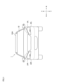
最初に、図1及び図2を参照して、本実施形態に係る車両システム2について以下に説明する。図1は、車両システム2が搭載された車両1の正面図である。図2は、車両システム2のブロック図である。車両1は、例えば、手動運転モード又は自動運転モードで走行可能な車両(自動車)である。First, the vehicle system 2 according to this embodiment will be described below with reference to Figures 1 and 2. Figure 1 is a front view of a
図2に示すように、車両システム2は、車両制御部3と、左側光照射システム4L(以下、単に光照射システム4Lという。)と、右側光照射システム4R(以下、単に光照射システム4Rという。)と、センサ5と、カメラ6と、レーダ7とを備える。さらに、車両システム2は、HMI(Human Machine Interface)8と、GPS(Global Positioning System)9と、無線通信部10と、記憶装置11と、ステアリングアクチュエータ12と、ステアリング装置13と、ブレーキアクチュエータ14と、ブレーキ装置15と、アクセルアクチュエータ16と、アクセル装置17とを備える。2, the vehicle system 2 includes a
車両制御部3は、車両1の走行を制御するように構成されている。車両制御部3は、例えば、少なくとも一つの電子制御ユニット(ECU:Electronic Control Unit)により構成されている。電子制御ユニットは、1以上のプロセッサと1以上のメモリを含むコンピュータシステム(例えば、SoC(System on a Chip)等)と、トランジスタ等のアクティブ素子及びパッシブ素子から構成される電子回路を含む。プロセッサは、例えば、CPU(Central Processing Unit)、MPU(Micro Processing Unit)、GPU(Graphics Processing Unit)及びTPU(Tensor Processing Unit)のうちの少なくとも一つを含む。CPUは、複数のCPUコアによって構成されてもよい。GPUは、複数のGPUコアによって構成されてもよい。メモリは、ROM(Read Only Memory)と、RAM(Random Access Memory)を含む。ROMには、車両制御プログラムが記憶されてもよい。例えば、車両制御プログラムは、自動運転用の人工知能(AI)プログラムを含んでもよい。RAMには、車両制御プログラム、車両制御データ及び/又は車両の周辺環境を示す周辺環境情報が一時的に記憶されてもよい。プロセッサは、ROMに記憶された各種車両制御プログラムから指定されたプログラムをRAM上に展開し、RAMとの協働で各種処理を実行するように構成されてもよい。また、コンピュータシステムは、ASIC(Application Specific Integrated Circuit)やFPGA(Field-Programmable Gate Array)等の非ノイマン型コンピュータによって構成されてもよい。さらに、コンピュータシステムは、ノイマン型コンピュータと非ノイマン型コンピュータの組み合わせによって構成されてもよい。The
光照射システム4Lは、照明ユニット45Lと、制御部46Lとを有する。照明ユニット45Lは、車両1の動作を示す情報を車両1の外部に向けて提示するように、車両1の周囲の路面にシーケンシャル照射パターンP(図3C参照)を照射するように構成されている。車両1の動作を示す情報としては、例えば、車両1の左折を示す情報である。例えば、車両1の左折が決定された場合に、照明ユニット45Lは、車両1の左折を外部に向けて提示するためにシーケンシャル照射パターンPを路面に照射する。シーケンシャル照射パターンPでは、時間経過に応じて路面に照射される照射パターンが連続的に変化する。シーケンシャル照射パターンPについての具体例については後述する。The
照明ユニット45Lの配置場所、描画方式、構成は特に限定されるものではない。例えば、図1に示すように、照明ユニット45Lは左側ヘッドランプ20Lの灯室内に配置されてもよい。また、照明ユニット45Lはルーフ100A上に配置されてもよい。また、照明ユニット45Lの描画方式としてプロジェクション方式やスキャン方式が採用されてもよい。照明ユニット45Lは、光を出射するように構成された光源部と、光源部から出射された光に基づいてシーケンシャル照射パターンPを形成した上で、シーケンシャル照射パターンPを路面に向けて照射するように構成された光学系とによって構成されてもよい。光源部は、例えば、複数のLED(Light Emitting Diode)素子又はLD(Laser Diode)素子によって構成されてもよい。光学系は、例えば、光源部から出射された光の偏向を制御するように構成された投影レンズ及び/又はリフレクタによって構成されてもよい。The location, drawing method, and configuration of the
また、照明ユニット45Lは、光を出射する光源部と、駆動ミラーと、レンズやミラー等の光学系によって構成されてもよい。駆動ミラーは、光源部から出射された光に基づいて路面に照射されるシーケンシャル照射パターンPを形成するように構成されている。駆動ミラーは、例えば、MEMS(Micro Electro Mechanical Systems)ミラー、DMD(Digital Mirror Device)又はブレードミラーによって構成されてもよい。例えば、光源部から出射された光がMEMSミラーによって路面上に走査されてもよい。このように、MEMSミラーによる光の走査によって照射パターンが路面上に投影されてもよい。
The
制御部46Lは、シーケンシャル照射パターンPが車両1の周囲の路面上に照射されるように照明ユニット45Lを制御するように構成されている。制御部46Lの配置場所は特に限定されるものではない。制御部46Lは、マイクロコントローラと、アナログ駆動制御回路とを備える。マイクロコントローラは、CPU等のプロセッサと、ROM等のメモリとを有する。アナログ駆動制御回路は、光源部に供給される電流を制御するように構成された電流制御回路及び/又は駆動ミラーを制御するように構成されたミラー駆動回路を有する。この点において、照明ユニット45Lが駆動ミラーを備えていない場合には、アナログ駆動制御回路は電流制御回路によって構成される。The
例えば、車両制御部3が車両1の左折を決定する場合又は運転者によるウインカーレバーの操作に応じて車両の左折が決定される場合に、車両制御部3は、シーケンシャル照射パターンPの照射を指示するための指示信号を制御部46Lに送信する。その後、制御部46Lは、車両制御部3から送信された指示信号に基づいて、路面上にシーケンシャル照射パターンPが照射されるように照明ユニット45Lの駆動を制御する。尚、本実施形態では、制御部46Lは、車両制御部3から分離されてもよいし、車両制御部3と一体的に構成されてもよい。For example, when the
光照射システム4Rは、上記した光照射システム4Lと同様の構成を有する。光照射システム4Rは、照明ユニット45Rと、制御部46Rとを有する。照明ユニット45Rは、車両1の動作を示す情報を車両1の外部に向けて提示するように、車両1の周囲の路面にシーケンシャル照射パターンを照射するように構成されている。車両1の動作を示す情報としては、例えば、車両1の右折を示す情報である。例えば、車両1の右折が決定された場合に、照明ユニット45Rは、車両1の右折を外部に向けて提示するためにシーケンシャル照射パターンを路面に照射する。照明ユニット45Rから出射されるシーケンシャル照射パターンの特徴は、照明ユニット45Lから出射されるシーケンシャル照射パターンPの特徴と基本的には同じものである。The
照明ユニット45Rの配置場所、描画方式、構成は特に限定されるものではない。例えば、図1に示すように、照明ユニット45Rは右側ヘッドランプ20Rの灯室内に配置されてもよい。また、照明ユニット45Rはルーフ100A上に配置されてもよい。The location, drawing method, and configuration of the
本実施形態では、説明の便宜上、車両1の前方側に配置された光照射システム4L,4Rについて説明されているが、光照射システムは車両1の後方側にも配置されてもよい。この場合、図3Aに示すように、左後側光照射システムの照明ユニット30Lが車両1の左側リアコンビネーションランプ60Lの灯室内に配置されてもよい。右後側光照射システムの照明ユニット30Rが車両1の右側リアコンビネーションランプ60Rの灯室内に配置されてもよい。照明ユニット30L,30Rは、車両1の後進を示す情報を車両1の外部に向けて提示するためにシーケンシャル照射パターンを路面上に照射するように構成されている。In this embodiment, for convenience of explanation, the
図2に戻ると、センサ5は、加速度センサ、速度センサ及びジャイロセンサのうち少なくとも一つを含む。センサ5は、車両1の走行状態を検出して、走行状態情報を車両制御部3に出力するように構成されている。センサ5は、運転者が運転席に座っているかどうかを検出する着座センサ、運転者の顔の方向を検出する顔向きセンサ、外部天候状態を検出する外部天候センサ及び車内に人がいるかどうかを検出する人感センサ等をさらに備えてもよい。Returning to FIG. 2, the
カメラ6は、例えば、CCD(Charge-Coupled Device)やCMOS(相補型MOS)等の撮像素子を含むカメラである。カメラ6は、車両1の周辺環境を示す画像データを取得した上で、当該画像データを車両制御部3に送信するように構成されている。車両制御部3は、送信された画像データに基づいて、周辺環境情報を取得する。ここで、周辺環境情報は、車両1の外部に存在する対象物(歩行者、他車両、標識等)に関する情報を含んでもよい。例えば、周辺環境情報は、車両1の外部に存在する対象物の属性に関する情報と、車両1に対する対象物の距離や位置に関する情報とを含んでもよい。The
レーダ7は、ミリ波レーダ、マイクロ波レーダ及びLiDARユニットのうちの少なくとも一つを含む。例えば、LiDARユニットは、車両1の周辺環境を検出するように構成されている。特に、LiDARユニットは、車両1の周辺環境を示す点群データを取得した上で、当該点群データを車両制御部3に送信するように構成されている。車両制御部3は、送信された点群データに基づいて、周辺環境情報を特定する。The
HMI8は、運転者からの入力操作を受付ける入力部と、車両1の走行情報等を運転者に向けて出力する出力部とから構成される。入力部は、ステアリングホイール、アクセルペダル、ブレーキペダル、車両1の運転モードを切替える運転モード切替スイッチ等を含む。出力部は、各種走行情報を表示する表示装置(例えば、HUD等)である。HUDは、車両1の走行情報をフロントウィンドウ60上に表示するように構成されている。GPS9は、車両1の現在位置情報を取得し、当該取得された現在位置情報を車両制御部3に出力するように構成されている。The HMI 8 is composed of an input unit that accepts input operations from the driver, and an output unit that outputs driving information of the
無線通信部10は、車両1の周囲にいる他車に関する情報(例えば、走行情報等)を他車から受信すると共に、車両1に関する情報(例えば、走行情報等)を他車に送信するように構成されている(車車間通信)。また、無線通信部10は、信号機や標識灯等のインフラ設備からインフラ情報を受信すると共に、車両1の走行情報をインフラ設備に送信するように構成されている(路車間通信)。また、無線通信部10は、歩行者が携帯する携帯型電子機器(スマートフォン、タブレット、ウェアラブルデバイス等)から歩行者に関する情報を受信すると共に、車両1の自車走行情報を携帯型電子機器に送信するように構成されている(歩車間通信)。車両1は、他車両、インフラ設備又は携帯型電子機器とアドホックモードにより直接通信してもよいし、アクセスポイントを介して通信してもよい。さらに、車両1は、インターネット等の通信ネットワークを介して他車両、インフラ設備又は携帯型電子機器と通信してもよい。The
記憶装置11は、ハードディスクドライブ(HDD)やSSD(Solid State Drive)等の外部記憶装置である。記憶装置11には、2次元又は3次元の地図情報及び/又は車両制御プログラムが記憶されてもよい。例えば、3次元の地図情報は、点群データによって構成されてもよい。記憶装置11は、車両制御部3からの要求に応じて、地図情報や車両制御プログラムを車両制御部3に出力するように構成されている。地図情報や車両制御プログラムは、無線通信部10と通信ネットワークを介して更新されてもよい。The
車両1が自動運転モードで走行する場合、車両制御部3は、走行状態情報、周辺環境情報、現在位置情報、地図情報等に基づいて、ステアリング制御信号、アクセル制御信号及びブレーキ制御信号のうち少なくとも一つを自動的に生成する。ステアリングアクチュエータ12は、ステアリング制御信号を車両制御部3から受信して、受信したステアリング制御信号に基づいてステアリング装置13を制御するように構成されている。ブレーキアクチュエータ14は、ブレーキ制御信号を車両制御部3から受信して、受信したブレーキ制御信号に基づいてブレーキ装置15を制御するように構成されている。アクセルアクチュエータ16は、アクセル制御信号を車両制御部3から受信して、受信したアクセル制御信号に基づいてアクセル装置17を制御するように構成されている。When the
一方、車両1が手動運転モードで走行する場合、車両制御部3は、アクセルペダル、ブレーキペダル及びステアリングホイールに対する運転者の手動操作に従って、ステアリング制御信号、アクセル制御信号及びブレーキ制御信号を生成する。このように、手動運転モードでは、ステアリング制御信号、アクセル制御信号及びブレーキ制御信号が運転者の手動操作によって生成されるので、車両1の走行は運転者により制御される。On the other hand, when the
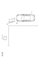
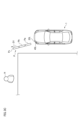
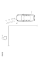
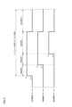
次に、図3Aから図4を参照することで、照明ユニット45Lから出射されるシーケンシャル照射パターンPについて以下に詳しく説明する。図3Aは、シーケンシャル照射パターンPのうち近位側照射パターンPa(第1の照射パターンの一例)が路面に照射された様子を示す図である。図3Bは、シーケンシャル照射パターンPのうち近位側照射パターンPa及び中間側照射パターンPb(第3の照射パターンの一例)が路面に照射された様子を示す図である。図3Cは、シーケンシャル照射パターンPのうち近位側照射パターンPa、中間側照射パターンPb及び遠位側照射パターンPc(第2の照射パターンの一例)が路面に照射された様子を示す図である。図3Dは、近位側照射パターンPa、中間側照射パターンPb及び遠位側照射パターンPcの照射が停止された様子を示す図である。図4は、近位側照射パターンPa、中間側照射パターンPb及び遠位側照射パターンPcの照射タイミングを説明するためのタイミングチャートを示す図である。尚、以降では、説明の便宜上、近位側照射パターンPa、中間側照射パターンPb、遠位側照射パターンPcをそれぞれ照射パターンPa,Pb,Pcという場合がある。
Next, the sequential irradiation pattern P emitted from the
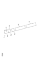
また、図8に示すように、以降の説明では、照明ユニット45Lの描画方式としてプロジェクション方式が採用されているものとする。図8に示すように、照明ユニット45Lは、光源部120と、光源部120から出射された光に基づいてシーケンシャル照射パターンPを路面に向けて照射するように構成された投影レンズ125とを有する。光源部120は、発光素子121~123と、発光素子121~123が搭載されるサブマウント基板124とを有する。発光素子121~123は、例えば、LEDにより構成されている。
As shown in Fig. 8, in the following description, it is assumed that the projection method is adopted as the drawing method of the
投影レンズ125は、発光素子121から出射された光に基づいて照射パターンPaを路面S上に形成するように構成されている。また、投影レンズ125は、発光素子122から出射された光に基づいて照射パターンPbを路面S上に形成するように構成されている。さらに、投影レンズ125は、発光素子123から出射された光に基づいて照射パターンPcを路面S上に形成するように構成されている。路面S上に投影された照射パターンPa~Pcの明るさ(照度)は、Pa>Pb>Pcの順番で大きくなる。つまり、照射パターンが車両1から離れる程、照射パターンの明るさは低くなる。The
制御部46Lは、マイクロコントローラ43Lと、電流制御回路42Lとを有する。マイクロコントローラ43Lは、車両制御部3からの指示信号の受信に応じて、所定の制御信号を電流制御回路42Lに送信するように構成されている。電流制御回路42Lは、光源部120の各発光素子121~123に供給される電流を制御するように構成されている。電流制御回路42Lは、各発光素子121~123に直流電流を供給すると共に、各発光素子に供給される直流電流の値を調整してもよい。また、電流制御回路42Lは、各発光素子121~123にパルス電流を供給すると共に、各発光素子に供給されるパルス電流の値及びDUTY比を調整してもよい。ここで、パルス電流では、ON時間(High状態)のパルスとOFF時間(Low状態)のパルスが所定の周期で連続する。DUTY比は、パルス電流の周期に対するパルスのON時間の比率%である。The
本実施形態では、電流制御回路42Lが各発光素子121~123に直流電流を供給する場合には、電流制御回路42Lは、DC/DCコンバータ等の電源回路と、図9Bに示すピーキング回路を備えてもよい(これについては後述する)。また、電流制御回路42Lが各発光素子121~123にパルス電流を供給する場合には、電流制御回路42Lは、DC/DCコンバータ等の電源回路と、PWM制御回路を備えてもよい。In this embodiment, when the
車両1の左折が決定された場合に、制御部46Lは、車両制御部3から送信された指示信号に基づいて、路面上にシーケンシャル照射パターンPが照射されるように照明ユニット45Lの駆動を制御する。図3Cに示すように、シーケンシャル照射パターンPは、近位側照射パターンPaと、中間側照射パターンPbと、遠位側照射パターンPcとを有する。When it is determined that the
シーケンシャル照射パターンPが路面上に照射される場合、最初に、照明ユニット45Lは、近位側照射パターンPaを車両1の前方の路面上に照射する(図3A参照)。次に、図3Bに示すように、照明ユニット45Lは、近位側照射パターンPaの照射を維持しながら、近位側照射パターンPaよりも車両1(照明ユニット45L)から離れた位置において中間側照射パターンPbを照射する。図3Bに示す状態では、路面上に照射された近位側照射パターンPaと中間側照射パターンPbは、D1方向において整列している。D1方向は、シーケンシャル照射パターンPの延出方向である。When the sequential irradiation pattern P is irradiated onto the road surface, first, the
次に、図3Cに示すように、照明ユニット45Lは、近位側照射パターンPaと中間側照射パターンPbの照射を維持しながら、中間側照射パターンPbよりも車両1(照明ユニット45L)から離れた位置において遠位側照射パターンPcを照射する。図3Cに示す状態では、路面上に照射された近位側照射パターンPaと、中間側照射パターンPbと、遠位側照射パターンPcは、D1方向において整列している。3C, the
照射パターンPa~Pcの形状は、矩形状となっているが、照射パターンPa~Pcの形状は特に限定されるものではない。また、図3Cの例では、照射パターンPa~Pcは互いに分離しているが、照射パターンPa~Pcは互いに接していてもよい。The shapes of the irradiation patterns Pa to Pc are rectangular, but the shapes of the irradiation patterns Pa to Pc are not particularly limited. In addition, in the example of FIG. 3C, the irradiation patterns Pa to Pc are separated from each other, but the irradiation patterns Pa to Pc may be in contact with each other.
次に、図3Dに示すように、照明ユニット45Lは、照射パターンPa~Pcの照射を停止する。時間経過に伴い照射パターンが連続的に変化するシーケンシャル照射パターンPでは、シーケンシャル照射パターンPの一周期Tsにおいて、照射パターンPa~Pcが順番に路面上に照射された後に照射パターンPa~Pcの全ての照射が停止される。シーケンシャル照射パターンPの周期Tsは、例えば、100msから500msの範囲内である。即ち、1分間におけるシーケンシャル照射パターンPの照射回数は、例えば、60回から600回の範囲内となる。特に、シーケンシャル照射パターンPの周期Tsは、シーケンシャルターンランプの順次点灯周期と同一であってもよい。
Next, as shown in FIG. 3D, the
図4に示すように、照射パターンPaのみが路面に照射される照射時間をTa、照射パターンPa,Pbの2つが路面に照射される照射時間をTb、照射パターンPa~Pcの全てが路面に照射される照射時間をTc、照射パターンPa~Pcの全ての照射が停止される停止時間をToffとした場合に、シーケンシャル照射パターンPの一周期Tsは、Ts=Ta+Tb+Tc+Toffとなる。As shown in Figure 4, if the irradiation time when only irradiation pattern Pa is irradiated onto the road surface is Ta, the irradiation time when both irradiation patterns Pa and Pb are irradiated onto the road surface is Tb, the irradiation time when all irradiation patterns Pa to Pc are irradiated onto the road surface is Tc, and the stop time when irradiation of all irradiation patterns Pa to Pc is stopped is Toff, then one period Ts of the sequential irradiation pattern P is Ts = Ta + Tb + Tc + Toff.
また、照明ユニット45Lから最も離れた位置に照射される照射パターンPcの明るさ(照度)は、照明ユニット45Lから最も近い位置に照射される照射パターンPaの明るさ(照度)よりも低くなる。このため、車両1の周辺に存在する歩行者H(図3C等参照)に対する照射パターンPcの視認性は、照射パターンPaの視認性と比較すると、相対的に低くなりがちとなる。このため、車両1の死角に存在する歩行者Hは、シーケンシャル照射パターンPの存在に気付きにくくなり、車両1の存在に気付きにくくなる。
In addition, the brightness (illuminance) of the irradiation pattern Pc irradiated at the position farthest from the
一方、本実施形態では、制御部46Lは、照射パターンPcの視認性が向上するように照明ユニット45Lを制御するように構成されている。具体的には、制御部46Lは、照射パターンPcが照射される照射時間Tcが照射時間Ta,Tbよりも長くなるように、照明ユニット45Lを制御している。このように、照射時間Tcが照射時間Ta,Tbよりも長くなるように設定されているため、車両1の周辺に存在する歩行者Hに対する照射パターンPcの視認性が向上し、歩行者Hに対するシーケンシャル照射パターンPの視認性が向上する。この結果として、歩行者Hは、シーケンシャル照射パターンPを通じて車両1の存在や動作を明確に把握することができる。On the other hand, in this embodiment, the
また、図4に示すタイミングチャートでは、Tc>Toff>Ta=Tbとなる。特に、Ta+Tb+Tc=3Ts/4となると共に、Toff=Ts/4となるように、各照射時間と停止時間が設定されている。この点において、通常想定されるシーケンシャル照射パターンでは、Ta=Tb=Tc=Toff=Ts/4となるところ、本実施形態では、照射時間Ta,Tbの各々がTs/4よりも小さくなるように設定されると共に、照射時間TcがTs/4よりも大きくなるように設定されている。このように、照射パターンPa,Pbの視認性に対して照射パターンPcの視認性を向上させることが可能となる。 In addition, in the timing chart shown in FIG. 4, Tc>Toff>Ta=Tb. In particular, each irradiation time and stop time are set so that Ta+Tb+Tc=3Ts/4 and Toff=Ts/4. In this respect, in a normally assumed sequential irradiation pattern, Ta=Tb=Tc=Toff=Ts/4, but in this embodiment, each of the irradiation times Ta and Tb is set to be smaller than Ts/4, and the irradiation time Tc is set to be larger than Ts/4. In this way, it is possible to improve the visibility of the irradiation pattern Pc relative to the visibility of the irradiation patterns Pa and Pb.
(シーケンシャル照射パターンPcの視認性を向上させるための第2の手法)
次に、図5を参照して照射パターンPcの視認性を向上させるための第2の手法について以下に説明する。図5は、路面に照射された遠位側照射パターンPcが振動している様子を示す図である。図5に示すように、制御部46Lは、照射パターンPcがD1方向に直交するD2方向において振動するように照明ユニット45Lを制御してもよい。
(Second Method for Improving Visibility of Sequential Irradiation Pattern Pc)
Next, a second method for improving the visibility of the irradiation pattern Pc will be described below with reference to Fig. 5. Fig. 5 is a diagram showing a state in which the distal side irradiation pattern Pc projected onto the road surface is vibrating. As shown in Fig. 5, the
例えば、制御部46Lは、照明ユニット45Lを構成するハウジングを物理的に振動させることで、照射パターンPcをD2方向に振動させてもよい。また、照明ユニット45Lの描画方式としてスキャン方式が採用される場合に、制御部46Lは、照射パターンPcがD2方向において振動するように照明ユニット45Lに設けられた駆動ミラーの駆動を制御してもよい。照射パターンPcの振動周波数は、例えば、5Hzから10Hzの範囲内であってもよい。この点において、振動周波数が5Hzから10Hzの範囲内に設定される場合、振動する照射パターンPcが人の注意を引きやすくなり、照射パターンPcの視認性をより向上させることが可能となる。また、照射時間Tcを照射時間Ta,Tcよりも大きくすると共に、照射パターンPcを振動させることで、歩行者Hに対する照射パターンPcの視認性をさらに向上させることができる。このように、照射パターンPcの視認性の向上によってシーケンシャル照射パターンPの視認性を向上させることができる。この結果、歩行者Hは、シーケンシャル照射パターンPを通じて車両1の存在や動作を明確に把握することができる。For example, the
尚、本例では、照射パターンPcはD2方向に振動しているが、照射パターンPcはD1方向に振動してもよい。このように、照射パターンPcが振動する方向は特に限定されるものではない。また、照射パターンPcが振動する場合には、照射時間Tcは照射時間Ta,Tbよりも長く設定されなくてもよい。In this example, the irradiation pattern Pc vibrates in the D2 direction, but the irradiation pattern Pc may vibrate in the D1 direction. In this way, the direction in which the irradiation pattern Pc vibrates is not particularly limited. In addition, when the irradiation pattern Pc vibrates, the irradiation time Tc does not have to be set longer than the irradiation times Ta and Tb.
(シーケンシャル照射パターンPcの視認性を向上させるための第3の手法)
次に、図6を参照して照射パターンPcの視認性を向上させるための第3の手法について以下に説明する。図6は、互いに分離した複数の矩形状の照射パターンPc1~Pc3により構成された遠位側照射パターンPcを示す図である。図6に示すように、照射パターンPcの形状は、照射パターンPa,Pbの形状とは相違している。特に、照射パターンPa,Pbの各々は、単一の矩形状の照射パターンによって構成されている一方で、照射パターンPcは、3つの矩形状の照射パターンPc1~Pc3により構成されている。照射パターンPc1~Pc3は、D1方向に整列すると共に、互いに分離している。
(Third method for improving visibility of sequential irradiation pattern Pc)
Next, a third method for improving the visibility of the irradiation pattern Pc will be described below with reference to FIG. 6. FIG. 6 is a diagram showing a distal side irradiation pattern Pc composed of a plurality of mutually separated rectangular irradiation patterns Pc1 to Pc3. As shown in FIG. 6, the shape of the irradiation pattern Pc is different from the shapes of the irradiation patterns Pa and Pb. In particular, each of the irradiation patterns Pa and Pb is composed of a single rectangular irradiation pattern, while the irradiation pattern Pc is composed of three rectangular irradiation patterns Pc1 to Pc3. The irradiation patterns Pc1 to Pc3 are aligned in the D1 direction and are separated from each other.
制御部46Lは、照射パターンPa,Pbが単一の矩形状の照射パターンによって構成されると共に、照射パターンPcが複数の照射パターンPc1~Pc3によって構成されるように、照明ユニット45Lの駆動を制御してもよい。照射パターンPcが複数の照射パターンPc1~Pc3によって構成されるため、照射パターンPcに対する歩行者Hの視認性が向上する。この結果として、シーケンシャル照射パターンPの視認性が向上するので、歩行者Hは、シーケンシャル照射パターンPを通じて車両1の存在や動作を明確に把握することができる。The
本例では、照射パターンPc1~Pc3は、同一タイミングで路面上に照射されてもよいし、異なるタイミングで路面上に照射されてもよい。例えば、照射パターンPc1~Pc3は、シーケンシャル照射パターンとして路面上に順次照射されてもよい。照射パターンPc1~Pc3がシーケンシャル照射パターンとして路面上に順番に照射される場合には、照射パターンPcの視認性をさらに向上させることが可能となる。さらに、照射パターンPcが複数の照射パターンPc1~Pc3によって構成される場合に、照射時間Tcを調整しつつ、照射パターンPcを振動させてもよい。この場合も同様に、照射パターンPcの視認性をさらに向上させることが可能となる。一方で、照射パターンPcが複数の照射パターンPc1~Pc3によって構成される場合に、照射時間Tcは照射時間Ta,Tbよりも長くなくてもよいと共に、照射パターンPcは振動しなくてもよい。In this example, the irradiation patterns Pc1 to Pc3 may be irradiated onto the road surface at the same timing, or may be irradiated onto the road surface at different timings. For example, the irradiation patterns Pc1 to Pc3 may be irradiated onto the road surface in sequence as a sequential irradiation pattern. When the irradiation patterns Pc1 to Pc3 are irradiated onto the road surface in sequence as a sequential irradiation pattern, it is possible to further improve the visibility of the irradiation pattern Pc. Furthermore, when the irradiation pattern Pc is composed of multiple irradiation patterns Pc1 to Pc3, the irradiation pattern Pc may be vibrated while adjusting the irradiation time Tc. In this case as well, it is possible to further improve the visibility of the irradiation pattern Pc. On the other hand, when the irradiation pattern Pc is composed of multiple irradiation patterns Pc1 to Pc3, the irradiation time Tc may not be longer than the irradiation times Ta and Tb, and the irradiation pattern Pc may not vibrate.
(シーケンシャル照射パターンPcの視認性を向上させるための第4の手法)
次に、図7から図10Bを参照して、シーケンシャル照射パターンPcの視認性を向上させるための第4の手法について以下に説明する。本例でも同様に、車両1に搭載された照明ユニット45Lは、図3A~図3Dに示すシーケンシャル照射パターンPを路面に照射するものとする。図7は、シーケンシャル照射パターンPのうち近位側照射パターンPa、中間側照射パターンPb及び遠位側照射パターンPcの照射タイミングを説明するためのタイミングチャートを示す図である。
(Fourth Method for Improving Visibility of Sequential Irradiation Pattern Pc)
Next, a fourth method for improving the visibility of the sequential irradiation pattern Pc will be described below with reference to Fig. 7 to Fig. 10B. Similarly in this example, the
図7に示すように、照射パターンPaのみが路面に照射される照射時間をTa、照射パターンPa,Pbの2つが路面に照射される照射時間をTb、照射パターンPa~Pcの全てが路面に照射される照射時間をTc、照射パターンPa~Pcの全ての照射が停止される停止時間をToffとした場合に、シーケンシャル照射パターンPの一周期Tsは、Ts=Ta+Tb+Tc+Toffとなる。As shown in Figure 7, if the irradiation time when only irradiation pattern Pa is irradiated onto the road surface is Ta, the irradiation time when both irradiation patterns Pa and Pb are irradiated onto the road surface is Tb, the irradiation time when all irradiation patterns Pa to Pc are irradiated onto the road surface is Tc, and the stop time when irradiation of all irradiation patterns Pa to Pc is stopped is Toff, then one period Ts of the sequential irradiation pattern P is Ts = Ta + Tb + Tc + Toff.
照射時間Taは、照射パターンPaの照射が開始される開始時間t1および照射パターンPbの照射が開始される開始時間t2によって規定される。照射時間Tbは、開始時間t2および照射パターンPcの照射が開始される開始時間t3によって規定される。照射時間Tcは、開始時間t3および照射パターンPa,Pb,Pcの照射が停止される停止時間t4によって規定される。 The irradiation time Ta is determined by the start time t1 when irradiation of the irradiation pattern Pa starts and the start time t2 when irradiation of the irradiation pattern Pb starts. The irradiation time Tb is determined by the start time t2 and the start time t3 when irradiation of the irradiation pattern Pc starts. The irradiation time Tc is determined by the start time t3 and the stop time t4 when irradiation of the irradiation patterns Pa, Pb, and Pc stops.
照射パターンPaでは、開始時間t1から所定時間tnまでの間における照射パターンPaの視認性が所定時間tnから停止時間t4までの間における照射パターンPaの視認性よりも高くなる。照射パターンPbでも同様に、開始時間t2から所定時間tnまでの間における照射パターンPbの視認性が所定時間tnから停止時間t4までの間における照射パターンPbの視認性よりも高くなる。照射パターンPcにおいても、開始時間t3から所定時間tnまでの間における照射パターンPcの視認性が所定時間tnから停止時間t4までの間における照射パターンPcの視認性よりも高くなる。開始時間t1,t2,t3と所定時間tnとの間の時間帯ΔTは、例えば、1msから200msの範囲内となる。In the irradiation pattern Pa, the visibility of the irradiation pattern Pa from the start time t1 to the specified time tn is higher than the visibility of the irradiation pattern Pa from the specified time tn to the stop time t4. Similarly, in the irradiation pattern Pb, the visibility of the irradiation pattern Pb from the start time t2 to the specified time tn is higher than the visibility of the irradiation pattern Pb from the specified time tn to the stop time t4. In the irradiation pattern Pc, the visibility of the irradiation pattern Pc from the start time t3 to the specified time tn is higher than the visibility of the irradiation pattern Pc from the specified time tn to the stop time t4. The time period ΔT between the start times t1, t2, t3 and the specified time tn is, for example, within the range of 1 ms to 200 ms.
この点において、時間帯ΔTが長くなる程、照射パターンの視認性が高くなる一方で、照明ユニット45Lの光源部120によって消費される消費電力が大きくなる。その一方で、時間帯ΔTが短くなる程、照射パターンの視認性が低くなる一方で、光源部120によって消費される消費電力は小さくなる。本実施形態では、照射パターンの視認性と光源部120の消費電力の2つの事項に着目することで、所定の時間帯ΔTが設定されている。In this regard, the longer the time period ΔT, the higher the visibility of the irradiation pattern, but the greater the power consumption consumed by the
次に、図9Aから図10Bを参照して、照射パターンの照射が開始される開始時間から所定時間tnとの間の時間帯ΔTにおいて照射パターンの視認性を向上させるための手法について以下に説明する。本例では、開始時間t3から所定時間tnとの間の時間帯ΔTにおいて照射パターンPcの視認性を向上させるための手法について説明する。時間帯ΔTにおける照射パターンPa,Pbの視認性を向上させるための手法は、時間帯ΔTにおける照射パターンPcの視認性を向上させるための手法と同一であるため、その説明については本明細書では割愛する。 Next, referring to Figures 9A to 10B, a method for improving the visibility of the irradiation pattern in a time period ΔT between the start time at which irradiation of the irradiation pattern begins and a predetermined time tn will be described below. In this example, a method for improving the visibility of the irradiation pattern Pc in a time period ΔT between the start time t3 and a predetermined time tn will be described. The method for improving the visibility of the irradiation patterns Pa, Pb in the time period ΔT is the same as the method for improving the visibility of the irradiation pattern Pc in the time period ΔT, so the description thereof will be omitted in this specification.
(各発光素子に供給される電流が直流電流である場合)
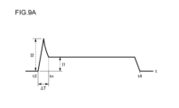
最初に、図9A及び図9Bを参照して、光源部120の発光素子123に供給される電流が直流電流である場合に、開始時間t3から所定時間tnとの間の時間帯ΔTにおいて照射パターンPcの視認性を向上させるための手法について説明する。図9Aは、照射パターンPcの照射が開始された開始時間t3から照射パターンPcの照射が停止される停止時間t4までの時間帯において、発光素子123に供給される直流電流の時間的変化を説明するための概念図である。図9Bは、直流電流を発光素子123に供給する電流制御回路42Lの構成の一部を説明するための図である。
(When the current supplied to each light-emitting element is a direct current)
First, a method for improving the visibility of the irradiation pattern Pc in a time period ΔT between a start time t3 and a predetermined time tn when the current supplied to the
図9Aに示すように、制御部46Lは、開始時間t3から所定時間tnまでの間における照射パターンPcの視認性が所定時間tnから停止時間t4までの間における照射パターンPcの視認性よりも高くなるように発光素子123に供給される電流を調整する。具体的には、制御部46Lは、開始時間t3から所定時間tnまでの間における照射パターンPcの明るさ(照度)が所定時間tnから停止時間t4までの間における照射パターンPcの明るさ(照度)よりも大きくなるように発光素子123に供給される電流を調整する。より具体的には、制御部46Lは、開始時間t3から所定時間tnの間における発光素子123に供給される直流電流の値が所定時間tnから停止時間t4の間における発光素子123に供給される直流電流の値よりも大きくなるように、発光素子123に供給される直流電流を調整する。9A, the
即ち、制御部46Lは、時間帯ΔTにおける照射パターンPcの視認性を向上させるために、時間帯ΔTにおける発光素子123に供給される直流電流の値を大きくするように構成されている。図9Aに示すように、電流制御回路42Lは、時間帯ΔTにおいて瞬間的に大きな直流電流を発光素子123に供給することで、時間帯ΔTにおける照射パターンPcの明るさを大きくする。このように、時間帯ΔTにおける照射パターンPcの視認性を高くすることが可能となる。時間帯ΔTにおけるピーク電流値I2は、定常状態における電流値I1のN倍(1<N<5)大きくなってもよい。That is, the
時間帯ΔTにおいてピーク電流値I2を発生させるために、電流制御回路42Lは、抵抗とコンデンサとによって構成されるピーキング回路を含んでもよい(図9B参照)。図9Bに示すように、抵抗R1によって発光素子123に供給される電流値I1が決定される。一方、抵抗R2によってピーク電流値I2が決定されると共に、コンデンサC1の静電容量によってピーク電流値I2に関連するピーク波形の幅(減衰時間)が決定される。抵抗R2が小さくなるとピーク電流値I2が大きくなる一方で、抵抗R2が大きくなるとピーク電流値I2が小さくなる。また、コンデンサC1の静電容量が小さくなるとピーク波形の幅が小さくなる一方で、静電容量が大きくなるとピーク波形の幅が大きくなる。このように、各素子の値を調整することで、時間帯ΔTにおいて最適な電流波形を設定することができる。In order to generate the peak current value I2 in the time period ΔT, the
本例によれば、時間帯ΔTにおいて瞬間的に大きな直流電流が発光素子123に供給されるため、時間帯ΔTにおける照射パターンPcの明るさが大きくなる。このように、車両1の周辺に存在する歩行者Hは路面上に照射された照射パターンPcの存在に気付きやすくなるため、歩行者Hに対する照射パターンPcの視認性が向上する。この結果、歩行者Hは、シーケンシャル照射パターンPを通じて車両1の存在や動作を明確に把握することができる。According to this example, a large DC current is instantaneously supplied to the light-emitting
(各発光素子に供給される電流がパルス電流である場合)
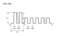
次に、図10A及び図10Bを参照して、光源部120の発光素子123に供給される電流がパルス電流である場合に、開始時間t3から所定時間tnとの間の時間帯ΔTにおいて照射パターンPcの視認性を向上させるための手法について説明する。図10Aは、開始時間t3から停止時間t4までの時間帯における、発光素子123に供給されるパルス電流の一例を説明するための概念図である。図10Bは、開始時間t3から停止時間t4までの時間帯における、発光素子123に供給されるパルス電流の他の一例を説明するための概念図である。
(When the current supplied to each light-emitting element is a pulse current)
Next, a method for improving the visibility of the irradiation pattern Pc in a time period ΔT between a start time t3 and a predetermined time tn when the current supplied to the
上記したように、発光素子123にパルス電流が供給される場合には、制御部46Lの電流制御回路42Lは、DC/DCコンバータ(例えば、スイッチングレギュレータ等)と、PWM制御回路を備えてもよい。As described above, when a pulsed current is supplied to the light-emitting
最初に、図10Aに示すようなパルス電流が発光素子123に供給される例について以下に説明する。図10Aに示すように、制御部46Lは、開始時間t3から所定時間tnまでの時間帯ΔTにおける照射パターンPcの視認性を向上させるために、時間帯ΔTにおける発光素子123に供給されるパルス電流の値I4を大きくするように構成されている。具体的には、電流制御回路42Lは、時間帯ΔTにおける発光素子123に供給されるパルス電流の値I4が所定時間tnから停止時間t4までの間における発光素子123に供給されるパルス電流の値I3よりも大きくなるようにパルス電流を調整するように構成されている。ここで、時間帯ΔTにおけるパルス電流の値I4は、所定時間tnから停止時間t4の間におけるパルス電流の値I3のN倍(1<N<5)となってもよい。一方で、時間帯ΔTにおけるパルス電流のDUTY比は、所定時間tnから停止時間t4の間におけるパルス電流のDUTY比と同じとなる。この場合、DUTY比は、例えば50%となる。First, an example in which a pulse current as shown in FIG. 10A is supplied to the light-emitting
このように、時間帯ΔTにおける照射パターンPcの明るさ(照度)が所定時間tnから停止時間t4までの間における照射パターンPcの明るさ(照度)よりも大きくなるため、時間帯ΔTにおける照射パターンPcの視認性が所定時間tnから停止時間t4までの間における照射パターンPcの視認性よりも高くなる。 In this way, since the brightness (illuminance) of the irradiation pattern Pc during the time period ΔT is greater than the brightness (illuminance) of the irradiation pattern Pc from the specified time tn to the stop time t4, the visibility of the irradiation pattern Pc during the time period ΔT is higher than the visibility of the irradiation pattern Pc from the specified time tn to the stop time t4.
図10Aに示す例によれば、時間帯ΔTにおいて発光素子123に供給されるパルス電流の値が大きくなるため、時間帯ΔTにおける照射パターンPcの明るさが大きくなる。このように、車両1の周辺に存在する歩行者Hは路面上に照射された照射パターンPcの存在に気付きやすくなるため、歩行者Hに対する照射パターンPcの視認性が向上する。この結果、歩行者Hは、シーケンシャル照射パターンPを通じて車両1の存在や動作を明確に把握することができる。10A, the value of the pulse current supplied to the light-emitting
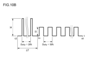
次に、図10Bに示すようなパルス電流が発光素子123に供給される例について以下に説明する。図10Bに示すように、制御部46Lは、開始時間t3から所定時間tnまでの時間帯ΔTにおける照射パターンPcの視認性を向上させるために、時間帯ΔTにおける発光素子123に供給されるパルス電流の値I4を大きくする一方で、当該パルス電流のDUTY比を小さくするように構成されている。具体的には、電流制御回路42Lは、時間帯ΔTにおける発光素子123に供給されるパルス電流の値I4が所定時間tnから停止時間t4までの間における発光素子123に供給されるパルス電流の値I3よりも大きくなるようにパルス電流を調整するように構成されている。さらに、電流制御回路42Lは、時間帯ΔTにおける発光素子123に供給されるパルス電流のDUTY比が所定時間tnから停止時間t4までの間における発光素子123に供給されるパルス電流のDUTY比よりも小さくなるようにパルス電流を調整するように構成されている。Next, an example in which a pulse current as shown in FIG. 10B is supplied to the light-emitting
時間帯ΔTにおけるパルス電流の値I4は、所定時間tnから停止時間t4の間におけるパルス電流の値I3のN倍(1<N<5)となってもよい。一方で、時間帯ΔTにおけるパルス電流のDUTY比は、所定時間tnから停止時間t4の間におけるパルス電流のDUTY比の1/N倍となってもよい。この場合、時間帯ΔTにおける(パルス電流の値)×(DUTY比)によって算出される値は、所定時間tnから停止時間t4の間における(パルス電流の値)×(DUTY比)によって算出される値と同一となる。このため、時間帯ΔTにおける照射パターンPcの実効的な明るさは、所定時間tnから停止時間t4の間における照射パターンPの実効的な明るさと同一となる。The pulse current value I4 in the time period ΔT may be N times (1<N<5) the pulse current value I3 between the specified time tn and the stop time t4. On the other hand, the duty ratio of the pulse current in the time period ΔT may be 1/N times the duty ratio of the pulse current between the specified time tn and the stop time t4. In this case, the value calculated by (pulse current value) x (duty ratio) in the time period ΔT is the same as the value calculated by (pulse current value) x (duty ratio) between the specified time tn and the stop time t4. Therefore, the effective brightness of the irradiation pattern Pc in the time period ΔT is the same as the effective brightness of the irradiation pattern P between the specified time tn and the stop time t4.
例えば、パルス電流の値I4がパルス電流の値I3の2.5倍である場合に、時間帯ΔTにおけるパルス電流のDUTY比が20%となる一方で、所定時間tnから停止時間t4の間におけるパルス電流のDUTY比は50%となってもよい。For example, if the pulse current value I4 is 2.5 times the pulse current value I3, the duty ratio of the pulse current during time period ΔT may be 20%, while the duty ratio of the pulse current between the specified time tn and the stop time t4 may be 50%.
また、照射パターンの瞬間的な光強度が高くなる程、人間の目に対する照射パターンの視認性が高くなるとともに、照射パターンの点滅周期が長くなる程、人間の目に対する照射パターンの視認性が高くなることが実験的に知られている。このため、本例では、時間帯ΔTにおいて、パルス電流の値を大きくしつつ、パルス電流のDUTY比を低くしている。It is also known experimentally that the higher the instantaneous light intensity of the irradiation pattern, the higher the visibility of the irradiation pattern to the human eye, and the longer the blinking period of the irradiation pattern, the higher the visibility of the irradiation pattern to the human eye. For this reason, in this example, the value of the pulse current is increased while the duty ratio of the pulse current is decreased during the time period ΔT.
このように、開始時間t3から停止時間t4までの間における照射パターンPcの実効的な明るさを略一定に維持しつつ、開始時間t3から所定時間tnの間の時間帯ΔTにおける照射パターンPcの視認性を所定時間tnから停止時間t4までの間における照射パターンPcの視認性よりも高くすることができる。したがって、車両1の周辺に存在する歩行者Hは路面上に照射された照射パターンPcの存在に気付きやすくなるため、歩行者Hに対する照射パターンPcの視認性が向上する。この結果、歩行者Hは、シーケンシャル照射パターンPを通じて車両1の存在や動作を明確に把握することができる。In this way, while maintaining the effective brightness of the irradiation pattern Pc between the start time t3 and the stop time t4 substantially constant, the visibility of the irradiation pattern Pc in the time period ΔT between the start time t3 and the predetermined time tn can be made higher than the visibility of the irradiation pattern Pc between the predetermined time tn and the stop time t4. Therefore, pedestrians H present around the
以上、本発明の実施形態について説明をしたが、本発明の技術的範囲が本実施形態の説明によって限定的に解釈されるべきではないのは言うまでもない。本実施形態は単なる一例であって、請求の範囲に記載された発明の範囲内において、様々な実施形態の変更が可能であることが当業者によって理解されるところである。本発明の技術的範囲は請求の範囲に記載された発明の範囲及びその均等の範囲に基づいて定められるべきである。 Although an embodiment of the present invention has been described above, it goes without saying that the technical scope of the present invention should not be interpreted as being limited by the description of this embodiment. This embodiment is merely an example, and it will be understood by those skilled in the art that various modifications of the embodiment are possible within the scope of the invention described in the claims. The technical scope of the present invention should be determined based on the scope of the invention described in the claims and its equivalents.
例えば、本実施形態では、車両1の動作の一例として、車両1の左折動作の際に路面に照射されるシーケンシャル照射パターンPについて主に説明している。一方で、車両1の他の動作(右折、前進、後進等)の際に路面上に照射されるシーケンシャル照射パターンについても上記シーケンシャル照射パターンPと同様の特徴を有する点に留意されたい。即ち、車両1の他の動作の際においても、遠位側照射パターンの視認性が向上したシーケンシャル照射パターンが路面上に照射される。さらに、車両1の他の動作の際においても、照射開始時間から所定時間tnまでの間の時間帯ΔTにおいて各照射パターンの視認性が向上する。For example, in this embodiment, as an example of the operation of the
また、本実施形態では、光照射システムが車両1に設けられているが、光照射システムは車両1以外の機器(例えば、信号機や街路灯等の交通インフラ設備)に設けられてもよい。
In addition, in this embodiment, the light irradiation system is provided in the
本出願は、2020年12月25日に出願された日本国特許出願(特願2020-217242号)に開示された内容及び2020年12月25日に出願された日本国特許出願(特願2020-217243号)に開示された内容を適宜援用する。This application incorporates as appropriate the contents disclosed in a Japanese patent application filed on December 25, 2020 (Patent Application No. 2020-217242) and the contents disclosed in a Japanese patent application filed on December 25, 2020 (Patent Application No. 2020-217243).
Claims (7)
路面にシーケンシャル照射パターンを照射するように構成された照明ユニットと、
前記シーケンシャル照射パターンが前記路面に照射されるように前記照明ユニットを制御するように構成された制御部と、を備え、
前記シーケンシャル照射パターンは、第1の照射パターンと、前記第1の照射パターンよりも前記照明ユニットから離れた位置に照射される第2の照射パターンとを有し、
前記第2の照射パターンは、前記第1の照射パターンが前記路面に照射された後に前記路面に照射され、
前記制御部は、前記照明ユニットの周辺に存在する対象物に対する前記第2の照射パターンの視認性が向上するように前記照明ユニットを制御するように構成されていて、
前記制御部は、前記第2の照射パターンの形状が前記第1の照射パターンの形状とは異なるように前記照明ユニットを制御するように構成されていて、
前記第2の照射パターンは、互いに分離した複数の矩形状の照射パターンによって構成され、
前記第1の照射パターンは、単一の矩形状の照射パターンにより構成されていて、
前記制御部は、前記第1の照射パターン及び前記第2の照射パターンを延出方向において整列し、前記延出方向において、前記第2の照射パターンの前記複数の矩形状の照射パターンの各々の幅が、前記第1の照射パターンの前記単一の矩形状の照射パターンの幅よりも小さくなるように前記照明ユニットを制御するように構成されている、光照射システム。 1. A light irradiation system comprising:
a lighting unit configured to project a sequential lighting pattern onto a road surface;
A control unit configured to control the lighting units so that the sequential illumination pattern is illuminated onto the road surface,
the sequential irradiation pattern includes a first irradiation pattern and a second irradiation pattern that is irradiated at a position farther from the lighting unit than the first irradiation pattern,
The second irradiation pattern is irradiated onto the road surface after the first irradiation pattern is irradiated onto the road surface,
The control unit is configured to control the lighting unit so as to improve visibility of the second irradiation pattern with respect to an object present around the lighting unit,
the control unit is configured to control the lighting unit such that a shape of the second irradiation pattern is different from a shape of the first irradiation pattern,
The second irradiation pattern is composed of a plurality of rectangular irradiation patterns separated from each other,
The first irradiation pattern is composed of a single rectangular irradiation pattern,
the control unit is configured to align the first irradiation pattern and the second irradiation pattern in an extension direction, and to control the lighting unit so that, in the extension direction, a width of each of the plurality of rectangular irradiation patterns of the second irradiation pattern is smaller than a width of the single rectangular irradiation pattern of the first irradiation pattern .
前記シーケンシャル照射パターンの一周期において、前記第1の照射パターン及び前記第2の照射パターンの両方が前記路面に照射される照射時間T2は、前記第1の照射パターンが前記路面に照射される照射時間T1よりも長い、請求項1に記載の光照射システム。 The lighting unit is configured to irradiate the road surface with the first irradiation pattern and then irradiate the road surface with both the first irradiation pattern and the second irradiation pattern,
2. The light irradiation system according to claim 1, wherein in one period of the sequential irradiation pattern, an irradiation time T2 during which both the first irradiation pattern and the second irradiation pattern are irradiated onto the road surface is longer than an irradiation time T1 during which the first irradiation pattern is irradiated onto the road surface.
前記シーケンシャル照射パターンの一周期において、前記第1の照射パターン及び前記第2の照射パターンの両方の照射が停止される停止時間Toffと、前記照射時間T1,T2は、T2>Toff>T1の関係を満たす、請求項2に記載の光照射システム。 The lighting unit is configured to irradiate the road surface with the first irradiation pattern, and then irradiate the road surface with both the first irradiation pattern and the second irradiation pattern, and then stop irradiating both the first irradiation pattern and the second irradiation pattern, in one cycle of the sequential irradiation pattern;
3. The light irradiation system according to claim 2, wherein in one period of the sequential irradiation pattern, a stop time Toff during which irradiation of both the first irradiation pattern and the second irradiation pattern is stopped and the irradiation times T1 and T2 satisfy a relationship of T2>Toff>T1.
前記照明ユニットは、前記車両の右折、左折若しくは後進を示す情報を前記車両の外部に向けて提示するように、前記車両の周囲の路面に前記シーケンシャル照射パターンを照射するように構成されている、請求項1から3のうちいずれか一項に記載の光照射システム。 The light irradiation system is provided in a vehicle,
4. The light illumination system according to claim 1, wherein the lighting unit is configured to illuminate a road surface around the vehicle with the sequential illumination pattern so as to present information indicating a right turn, a left turn, or a reverse movement of the vehicle toward an outside of the vehicle.
前記シーケンシャル照射パターンは、第1の照射パターンと、前記第1の照射パターンよりも前記照明ユニットから離れた位置に照射される第2の照射パターンとを有し、
前記第2の照射パターンは、前記第1の照射パターンが前記路面に照射された後に前記路面に照射され、
前記照明ユニットは、前記照明ユニットの周辺に存在する対象物に対する前記第2の照射パターンの視認性が向上するように前記シーケンシャル照射パターンを照射するように構成されていて、
前記第2の照射パターンの形状は、前記第1の照射パターンの形状とは異なり、
前記第2の照射パターンは、互いに分離した複数の矩形状の照射パターンによって構成され、
前記第1の照射パターンは、単一の矩形状の照射パターンにより構成されていて、
前記第1の照射パターン及び前記第2の照射パターンは延出方向において整列し、前記延出方向において、前記第2の照射パターンの前記複数の矩形状の照射パターンの各々の幅が、前記第1の照射パターンの前記単一の矩形状の照射パターンの幅よりも小さくなる、照明ユニット。 1. A lighting unit configured to project a sequential illumination pattern onto a road surface, comprising:
the sequential irradiation pattern includes a first irradiation pattern and a second irradiation pattern that is irradiated at a position farther from the lighting unit than the first irradiation pattern,
The second irradiation pattern is irradiated onto the road surface after the first irradiation pattern is irradiated onto the road surface,
The lighting unit is configured to irradiate the sequential irradiation pattern so as to improve visibility of the second irradiation pattern on an object present around the lighting unit,
The shape of the second irradiation pattern is different from the shape of the first irradiation pattern,
The second irradiation pattern is composed of a plurality of rectangular irradiation patterns separated from each other,
The first irradiation pattern is composed of a single rectangular irradiation pattern,
The first irradiation pattern and the second irradiation pattern are aligned in an extension direction, and in the extension direction, a width of each of the plurality of rectangular irradiation patterns of the second irradiation pattern is smaller than a width of the single rectangular irradiation pattern of the first irradiation pattern .
Priority Applications (1)
| Application Number | Priority Date | Filing Date | Title |
|---|---|---|---|
| JP2025020625A JP2025072602A (en) | 2020-12-25 | 2025-02-12 | Light irradiation system and lighting unit |
Applications Claiming Priority (5)
| Application Number | Priority Date | Filing Date | Title |
|---|---|---|---|
| JP2020217242 | 2020-12-25 | ||
| JP2020217242 | 2020-12-25 | ||
| JP2020217243 | 2020-12-25 | ||
| JP2020217243 | 2020-12-25 | ||
| PCT/JP2021/043630 WO2022137995A1 (en) | 2020-12-25 | 2021-11-29 | Light irradiation system and lighting unit |
Related Child Applications (1)
| Application Number | Title | Priority Date | Filing Date |
|---|---|---|---|
| JP2025020625A Division JP2025072602A (en) | 2020-12-25 | 2025-02-12 | Light irradiation system and lighting unit |
Publications (2)
| Publication Number | Publication Date |
|---|---|
| JPWO2022137995A1 JPWO2022137995A1 (en) | 2022-06-30 |
| JP7635262B2 true JP7635262B2 (en) | 2025-02-25 |
Family
ID=82157695
Family Applications (2)
| Application Number | Title | Priority Date | Filing Date |
|---|---|---|---|
| JP2022572017A Active JP7635262B2 (en) | 2020-12-25 | 2021-11-29 | Light irradiation system and lighting unit |
| JP2025020625A Pending JP2025072602A (en) | 2020-12-25 | 2025-02-12 | Light irradiation system and lighting unit |
Family Applications After (1)
| Application Number | Title | Priority Date | Filing Date |
|---|---|---|---|
| JP2025020625A Pending JP2025072602A (en) | 2020-12-25 | 2025-02-12 | Light irradiation system and lighting unit |
Country Status (2)
| Country | Link |
|---|---|
| JP (2) | JP7635262B2 (en) |
| WO (1) | WO2022137995A1 (en) |
Citations (4)
| Publication number | Priority date | Publication date | Assignee | Title |
|---|---|---|---|---|
| JP2009149152A (en) | 2007-12-19 | 2009-07-09 | Toyota Central R&D Labs Inc | Information display device |
| EP3178698A1 (en) | 2015-12-07 | 2017-06-14 | SL Corporation | Automotive lamp and method of controlling the same |
| WO2018138842A1 (en) | 2017-01-26 | 2018-08-02 | 三菱電機株式会社 | Irradiation control device and irradiation method |
| WO2019053890A1 (en) | 2017-09-15 | 2019-03-21 | 三菱電機株式会社 | Illumination apparatus and illumination method |
Family Cites Families (3)
| Publication number | Priority date | Publication date | Assignee | Title |
|---|---|---|---|---|
| JP2009248598A (en) * | 2008-04-01 | 2009-10-29 | Toyota Motor Corp | Road surface depiction device |
| JP6803687B2 (en) * | 2016-06-15 | 2020-12-23 | スタンレー電気株式会社 | Lighting control device for vehicle lamps, vehicle lamp system |
| JP7274263B2 (en) * | 2018-04-12 | 2023-05-16 | マクセル株式会社 | Direction display device |
-
2021
- 2021-11-29 JP JP2022572017A patent/JP7635262B2/en active Active
- 2021-11-29 WO PCT/JP2021/043630 patent/WO2022137995A1/en not_active Ceased
-
2025
- 2025-02-12 JP JP2025020625A patent/JP2025072602A/en active Pending
Patent Citations (4)
| Publication number | Priority date | Publication date | Assignee | Title |
|---|---|---|---|---|
| JP2009149152A (en) | 2007-12-19 | 2009-07-09 | Toyota Central R&D Labs Inc | Information display device |
| EP3178698A1 (en) | 2015-12-07 | 2017-06-14 | SL Corporation | Automotive lamp and method of controlling the same |
| WO2018138842A1 (en) | 2017-01-26 | 2018-08-02 | 三菱電機株式会社 | Irradiation control device and irradiation method |
| WO2019053890A1 (en) | 2017-09-15 | 2019-03-21 | 三菱電機株式会社 | Illumination apparatus and illumination method |
Also Published As
| Publication number | Publication date |
|---|---|
| JPWO2022137995A1 (en) | 2022-06-30 |
| WO2022137995A1 (en) | 2022-06-30 |
| JP2025072602A (en) | 2025-05-09 |
Similar Documents
| Publication | Publication Date | Title |
|---|---|---|
| JP7235659B2 (en) | Vehicle lighting system and vehicle | |
| JP7152413B2 (en) | Sensing system and vehicle | |
| US11351912B2 (en) | Vehicle headlamp system and vehicle lamp system | |
| US10602331B2 (en) | Inter-vehicle communication system, vehicle system, vehicle illumination system and vehicle | |
| JP6970612B2 (en) | Vehicle lighting system and vehicle | |
| CN110154881B (en) | Lighting system for vehicle and vehicle | |
| US11454539B2 (en) | Vehicle lamp | |
| JP7043256B2 (en) | Vehicle lighting system and vehicle | |
| US10933802B2 (en) | Vehicle illumination system and vehicle | |
| US12117620B2 (en) | Vehicle display system and vehicle | |
| JP7273839B2 (en) | lighting system | |
| JP2018058542A (en) | Vehicular illumination apparatus | |
| JPWO2018123429A1 (en) | Lighting device | |
| JP7635262B2 (en) | Light irradiation system and lighting unit | |
| JP7229931B2 (en) | vehicle lamp system | |
| US20250020304A1 (en) | Road surface drawing lamp and road surface drawing lamp system | |
| JP7474133B2 (en) | Vehicle lighting fixtures | |
| JP2020144777A (en) | Vehicle system | |
| JP2019217951A (en) | Control device of vehicle lighting fixture, control method of vehicle lighting fixture, vehicle lighting system, and vehicle | |
| JP2019159772A (en) | Vehicle system | |
| JP2022052142A (en) | Vehicular head lamp system, and control method of vehicular head lamp system |
Legal Events
| Date | Code | Title | Description |
|---|---|---|---|
| A621 | Written request for application examination |
Free format text: JAPANESE INTERMEDIATE CODE: A621 Effective date: 20240821 |
|
| A131 | Notification of reasons for refusal |
Free format text: JAPANESE INTERMEDIATE CODE: A131 Effective date: 20241015 |
|
| A521 | Request for written amendment filed |
Free format text: JAPANESE INTERMEDIATE CODE: A523 Effective date: 20241127 |
|
| TRDD | Decision of grant or rejection written | ||
| A01 | Written decision to grant a patent or to grant a registration (utility model) |
Free format text: JAPANESE INTERMEDIATE CODE: A01 Effective date: 20250121 |
|
| A61 | First payment of annual fees (during grant procedure) |
Free format text: JAPANESE INTERMEDIATE CODE: A61 Effective date: 20250212 |
|
| R150 | Certificate of patent or registration of utility model |
Ref document number: 7635262 Country of ref document: JP Free format text: JAPANESE INTERMEDIATE CODE: R150 |