JP7635207B2 - Dental flosser having means for adjusting floss tension - Patents.com - Google Patents
Dental flosser having means for adjusting floss tension - Patents.com Download PDFInfo
- Publication number
- JP7635207B2 JP7635207B2 JP2022511263A JP2022511263A JP7635207B2 JP 7635207 B2 JP7635207 B2 JP 7635207B2 JP 2022511263 A JP2022511263 A JP 2022511263A JP 2022511263 A JP2022511263 A JP 2022511263A JP 7635207 B2 JP7635207 B2 JP 7635207B2
- Authority
- JP
- Japan
- Prior art keywords
- floss
- bundle
- floss bundle
- dental flosser
- attachment member
- Prior art date
- Legal status (The legal status is an assumption and is not a legal conclusion. Google has not performed a legal analysis and makes no representation as to the accuracy of the status listed.)
- Active
Links
Images


Classifications
-
- A—HUMAN NECESSITIES
- A61—MEDICAL OR VETERINARY SCIENCE; HYGIENE
- A61C—DENTISTRY; APPARATUS OR METHODS FOR ORAL OR DENTAL HYGIENE
- A61C15/00—Devices for cleaning between the teeth
- A61C15/04—Dental floss; Floss holders
- A61C15/046—Flossing tools
-
- A—HUMAN NECESSITIES
- A61—MEDICAL OR VETERINARY SCIENCE; HYGIENE
- A61C—DENTISTRY; APPARATUS OR METHODS FOR ORAL OR DENTAL HYGIENE
- A61C15/00—Devices for cleaning between the teeth
- A61C15/04—Dental floss; Floss holders
- A61C15/041—Dental floss
-
- A—HUMAN NECESSITIES
- A61—MEDICAL OR VETERINARY SCIENCE; HYGIENE
- A61C—DENTISTRY; APPARATUS OR METHODS FOR ORAL OR DENTAL HYGIENE
- A61C15/00—Devices for cleaning between the teeth
- A61C15/04—Dental floss; Floss holders
- A61C15/046—Flossing tools
- A61C15/047—Flossing tools power-driven
Landscapes
- Health & Medical Sciences (AREA)
- Dentistry (AREA)
- Epidemiology (AREA)
- Life Sciences & Earth Sciences (AREA)
- Animal Behavior & Ethology (AREA)
- General Health & Medical Sciences (AREA)
- Public Health (AREA)
- Veterinary Medicine (AREA)
- Brushes (AREA)
Description
本発明は、一般的には歯および口腔の清浄装置に関し、特には、フロス張力を調整するための手段を有する手持ち式のデンタルフロッサ(hand-held dental flosser)(例えば、デンタルフロスピック(dental floss pick)またはデンタルフロスホルダ(dental floss holder))に関し、このようなデンタルフロッサの製造方法および使用方法にも関する。 The present invention relates generally to dental and oral cleaning devices, and more particularly to hand-held dental flossers (e.g., dental floss picks or dental floss holders) having means for adjusting floss tension, as well as methods of making and using such dental flossers.
一般的には、歯の間の隙間および歯の表面は、磨き、機械駆動式の水噴射、ようじなどの様々な方法によって清浄可能であり、デンタルフロスまたはデンタルテープまたは類似の糸によっても清浄可能である。デンタルフロスとは、細い繊維からなるひもであって、一般的には歯から食べ物および歯垢を歯から除去するように使用される。 In general, the gaps between teeth and the surfaces of teeth can be cleaned by a variety of methods, including brushing, mechanically driven water jets, toothpicks, and also with dental floss or dental tape or similar floss. Dental floss is a string of fine fibers that is typically used to remove food and plaque from the teeth.
齲蝕(虫歯)の主な原因の1つ、そして歯周病(歯茎および歯根)の重要な原因の1つは、歯の表面に発生する歯垢の形成にある。除去すると、新たな歯垢は24時間内に再度に形成可能である。よって、最適な歯の衛生および健康を維持するために、毎日には少なくとも1回のフロスの使用が必要とされる。 One of the main causes of dental caries (tooth decay) and one of the important causes of periodontal disease (gum and root) is the formation of plaque on the tooth surface. Once removed, new plaque can form again within 24 hours. Therefore, flossing at least once each day is required to maintain optimal dental hygiene and health.
典型的なデンタルフロスを使用する手順が難しく冗長であるため、多くの人は日常的に歯にフロスを使用していない。手持ち式のデンタルフロッサ(フロスホルダまたはフロスピックとも知られている)の使用によれば、フロスの使用がより便利かつより容易になる。一般的には、デンタルフロッサは、薄いプラスチック本体(またはハンドル)から延びた2つの先端部を含む。フロス束(floss strand)が当該2つの先端部の間において張られる。一例として、「Dental floss pick」と題する米国意匠出願第D618396号には典型的なデンタルフロッサが開示されている。典型的なデンタルフロッサは、多くの場合では硬くて柔軟性のないプラスチック材料から製造され、2つの先端部の間のフロス束は固定されている。 Many people do not floss their teeth on a regular basis because the process of using a typical dental floss is difficult and lengthy. The use of a handheld dental flosser (also known as a floss holder or floss pick) makes flossing more convenient and easier. Typically, a dental flosser includes two tips extending from a thin plastic body (or handle). A floss strand is stretched between the two tips. As an example, U.S. Design Application No. D618396, entitled "Dental floss pick," discloses a typical dental flosser. A typical dental flosser is often fabricated from a hard, inflexible plastic material, and the floss strand is fixed between the two tips.
典型的なデンタルフロッサの主な欠点は、以下通りである。すなわち、フロス束の張力が固定されたものなので、デンタルフロスを歯の間に適切に挿入するという、デンタルフロス束が張力を維持すべき動作に必要とされる比較的高い張力によって、デンタルフロス束は歯間空間から離れた歯の輪郭の周りで湾曲することができない。その結果、歯間表面以外の歯の表面からの歯垢および細菌を適切に清浄することは容易に実行できない。 The main drawback of a typical dental flosser is that the tension of the floss bundle is fixed, and the relatively high tension required to properly insert the floss between the teeth, which the floss bundle must maintain, does not allow the floss bundle to curve around the contours of the teeth away from the interdental spaces. As a result, proper cleaning of plaque and bacteria from tooth surfaces other than the interdental surfaces cannot be easily accomplished.
よって、改良され、フロス張力を調整するための手段を有し、歯の輪郭の周りでより効率的に歯の表面(歯の前面、後面、および歯間表面を含む)を清浄する手持ち式のデンタルフロッサの提供が望ましい Thus, it would be desirable to provide an improved handheld dental flosser that has a means for adjusting floss tension and cleans tooth surfaces (including the front, back, and interdental surfaces) more efficiently around the tooth contours.
図面には本発明の非限定的な実施例が示されている。 The drawings show non-limiting examples of the present invention.
以下の説明を通して、具体的な詳細は、本発明についてより完全に理解してもらうために記載されている。しかしながら、本発明はこれらの委細をなくても実行され得る。他の例示において、発明のポイントが無益に逸らされることを回避するために、周知の要素については詳細に示されていないまたは説明されていない。よって、明細書および図面は、制限的なシーンに関するものよりも、例示に関するものである。 Throughout the following description, specific details are set forth to provide a more complete understanding of the present invention. However, the present invention may be practiced without these details. In other instances, well-known elements have not been shown or described in detail to avoid unnecessarily obscuring the point of the invention. Thus, the specification and drawings are to be regarded as illustrative rather than restrictive.
本発明の1つの概念は手持ち式のデンタルフロッサに関する。デンタルフロッサは、互いに離間された2つのアーム(第1アームおよび第2アーム)を有するU形部と、U形部と接続された手持ち部とを備える。デンタルフロッサはフロス束をさらに備える。フロス束は第1末端および第2末端を有する。フロス束の第1末端はU形部の第1アームに固定的に取り付けられ、よって、フロス束の第1末端の位置はU形部の第1アームに対して移動しない。当該取り付けの位置は、U形部の第1アームの末端であってもよく。U形部の第1アームの末端の近傍であってもよい。フロス束の第2末端はフロス束取り付けピースに取り付けられる。ユーザは、フロス束の張力を増加する、減少するまたは維持するように、手動的に(または機械的にまたは電気的に)フロス束取り付けピースを操作し、フロス束の第2末端を移動させることができる。フロス束の中間部がU形部の第2アームにスライド可能に装着され、よって、フロス束の中間部はU形部の第2アームに対してスライド可能である。フロス束の中間部をU形部の第2アームにスライド可能に装着させるために、装着可能な機構の部材、例えば、固定滑車、枢軸、輪、ロータ、チャネル、通路、穴、または他の適した手段は適用され得る。装着機構の位置は、U形部の第2アームの末端であってもよく。U形部の第2アームの末端の近傍であってもよい。装着機構によれば、フロス束がU形部の第2アームから完全に分離することを防ぎながら、フロス束がスライド可能にすることができる。 One aspect of the present invention relates to a handheld dental flosser. The dental flosser includes a U-shaped portion having two arms (a first arm and a second arm) spaced apart from one another, and a hand-held portion connected to the U-shaped portion. The dental flosser further includes a floss bundle. The floss bundle has a first end and a second end. The first end of the floss bundle is fixedly attached to the first arm of the U-shaped portion, such that the position of the first end of the floss bundle does not move relative to the first arm of the U-shaped portion. The attachment position may be at the end of the first arm of the U-shaped portion, or near the end of the first arm of the U-shaped portion. The second end of the floss bundle is attached to a floss bundle attachment piece. A user may manually (or mechanically or electrically) manipulate the floss bundle attachment piece to move the second end of the floss bundle to increase, decrease or maintain tension on the floss bundle. The middle portion of the floss bundle is slidably attached to the second arm of the U-shaped portion, such that the middle portion of the floss bundle is slidable relative to the second arm of the U-shaped portion. To slidably attach the middle portion of the floss bundle to the second arm of the U-shaped portion, an attachable mechanism member, such as a fixed pulley, a pivot, a wheel, a rotor, a channel, a passage, a hole, or other suitable means, may be applied. The location of the attachment mechanism may be at the end of the second arm of the U-shaped portion. It may be near the end of the second arm of the U-shaped portion. The attachment mechanism allows the floss bundle to slide while preventing the floss bundle from being completely separated from the second arm of the U-shaped portion.
本発明の1つの概念は手持ち式のデンタルフロッサに関する。デンタルフロッサは、互いに離間された2つのアームを有するU形部と、U形部と接続された手持ち部と、手持ち部(もしくはU形部)から分離された、または手持ち部(もしくはU形部)と取り外し可能に接続されたスライド部材部とを備える。いくつかの実施例において、U形部、手持ち部、およびスライド部材部の全部は、同じ適した材料(例えば、プラスチック)で製造され、射出成形プロセスを用いて製造される。いくつかの実施例において、デンタルフロッサは、互いに接続されたU形部と手持ち部とスライド部材部とを有する一体成形の製品として製造される。スライド部材部は、狭い接続点において手持ち部またはU形部に接続され得て、ユーザは、力を接続点に加えてスライド部材部を手持ち部またはU形部から分離させることができ、よって、スライド部材が分離された要素となる。 One aspect of the present invention relates to a handheld dental flosser. The dental flosser comprises a U-shaped portion having two arms spaced apart from each other, a hand-held portion connected to the U-shaped portion, and a slide member portion separate from or removably connected to the hand-held portion (or U-shaped portion). In some embodiments, the U-shaped portion, the hand-held portion, and the slide member portion are all made of the same suitable material (e.g., plastic) and manufactured using an injection molding process. In some embodiments, the dental flosser is manufactured as a one-piece product with the U-shaped portion, the hand-held portion, and the slide member portion connected to each other. The slide member portion may be connected to the hand-held portion or the U-shaped portion at a narrow connection point, and a user may apply force to the connection point to separate the slide member portion from the hand-held portion or the U-shaped portion, such that the slide member becomes a separate element.
デンタルフロッサはフロス束をさらに備える。いくつかの実施例において、フロス束はデンタルフロッサとともにその場で射出成形される。フロス束は両端を有する。フロス束の第1端はU形部の第1アーム(すなわち、手持ち部に対して遠位側のアーム)に固定されて埋め込まれる。フロス束の第2端はスライド部材に固定されて埋め込まれる。フロス束の端部を固く固定する方法はいくつかがある。方法の一例は、射出成形プロセスにおいてフロス束の端部をプラスチック材から延ばして、フロス束の端部を加熱してまたは燃やして、フロスより大きい直径を有するビーズ(beads)に合体させる方法であり、当該フロスによれば、フロス束はプラスチック材から引き抜かれることが回避される。 The dental flosser further comprises a floss bundle. In some embodiments, the floss bundle is injection molded in situ with the dental flosser. The floss bundle has two ends. A first end of the floss bundle is fixedly embedded in a first arm of the U-shaped portion (i.e., the arm distal to the handle). A second end of the floss bundle is fixedly embedded in the slide member. There are several ways to rigidly secure the ends of the floss bundle. One method is to extend the ends of the floss bundle from the plastic material during the injection molding process and heat or burn the ends of the floss bundle to coalesce into beads having a larger diameter than the floss, which prevents the floss bundle from being pulled out of the plastic material.
フロス束の中間部分は、U形部の第2アーム内のチャネルを通っている。当該チャネルは、フロス束がンタルフロッサとともにその場で射出成形されるときに生成されるものである。フロス束の中間部分はU形部の第2アーム内のチャネルにおいてスライド可能である。 The middle portion of the floss bundle passes through a channel in the second arm of the U-shaped section. The channel is created when the floss bundle is injection molded in situ with the axial flosser. The middle portion of the floss bundle is slidable in the channel in the second arm of the U-shaped section.
フロス束はデンタルフロッサに対して3つの接触点(または接触区域)を有する。フロス束は、U形部の第1アームに固定された第1端を有する。これが第1接触点である。フロス束は、スライド部材に固定された第2端を有する。これが第2接触点である。その第1端とその第2端との間、フロス束は、U形部の第2アーム内のチャネルまたは何かの他の装着機構を通ることによって、U形部の第2アームにも接触する。これが第3接触点である。この概念では、フロス束に関してU形部の第2アームの機能は固定滑車と同様であり、当該第2アームによって、フロス束が第2アームに装着されて第2アームの周りでスライドすることができる。フロス束はその両端間の長さが固定である。しかしながら、U形部の第1アームと第2アームとの間のフロス束の部分はユーザによって調整可能である。 The floss bundle has three contact points (or contact areas) with the dental flosser. The floss bundle has a first end that is fixed to the first arm of the U-shaped section. This is the first contact point. The floss bundle has a second end that is fixed to the sliding member. This is the second contact point. Between its first and second ends, the floss bundle also contacts the second arm of the U-shaped section by passing through a channel or some other attachment mechanism in the second arm of the U-shaped section. This is the third contact point. In this concept, the function of the second arm of the U-shaped section with respect to the floss bundle is similar to a fixed pulley, allowing the floss bundle to be attached to and slide around the second arm. The floss bundle has a fixed length between its ends. However, the portion of the floss bundle between the first and second arms of the U-shaped section is adjustable by the user.
本発明の1つの概念は、ここで開示される手持ち式のデンタルフロッサを使用する方法に関する。フロス束取り付けピース(例えば、スライド部材部)がデンタルフロッサの手持ち部に接続された場合、ユーザはまずデンタルフロッサからスライド部材部を分離させてもよい。次に、ユーザは、U形部の第1アームと第2アームとの間のフロス束の張力を増加するまたは維持するように、フロス束を引っ張ってまたは保持してもよい。代替的に、ユーザは、フロス束の張力を増加するまたは維持するように、フロス束取り付けピースを機械的または電気的な機構に装着してもよい。フロス束が張力のかかっている状態にあるとき、ユーザはデンタルフロッサを操作してフロス束を隣接する2つの歯の間に挿入してもよい。フロス束が歯間空間内に挿入されると、ユーザは、手動的に、または、機械的または電気的な機構を介して、フロス束の張力を減少させてもよい(すなわち、フロス束を緩ませてもよい)。このようにすれば、フロス束は歯の輪郭の周りで曲がって当該歯の複数の表面を清浄することができ、当該複数の表面は、歯間表面だけではなく、歯の前面と後面とも含む。ユーザが歯を清浄した後、ユーザは、フロス束の張力を再び増加してまたは維持して、歯の間からフロス束を引き出してもよい。ユーザは、フロス束の張力を調整してユーザの口腔内の他の歯を清浄するように、このプロセスを繰り返してもよい。 One aspect of the present invention relates to a method of using the handheld dental flosser disclosed herein. When the floss bundle attachment piece (e.g., slide member portion) is connected to the handheld portion of the dental flosser, the user may first separate the slide member portion from the dental flosser. The user may then pull or hold the floss bundle to increase or maintain tension on the floss bundle between the first and second arms of the U-shaped portion. Alternatively, the user may attach the floss bundle attachment piece to a mechanical or electrical mechanism to increase or maintain tension on the floss bundle. When the floss bundle is in tension, the user may manipulate the dental flosser to insert the floss bundle between two adjacent teeth. Once the floss bundle is inserted into the interdental space, the user may decrease tension on the floss bundle (i.e., release the floss bundle) either manually or via a mechanical or electrical mechanism. In this manner, the floss bundle can bend around the contours of the tooth to clean multiple surfaces of the tooth, including the front and back surfaces of the tooth as well as the interdental surfaces. After the user has cleaned the tooth, the user may again increase or maintain tension on the floss bundle to pull the floss bundle from between the teeth. The user may repeat this process by adjusting the tension on the floss bundle to clean other teeth in the user's mouth.
いくつかの実施例において、デンタルフロッサは、手持ち部において長手方向のガイド溝またはチャネルを備える。当該溝またはチャネルは、スライド部材が当該溝またはチャネルに嵌合できて当該溝またはチャネルに沿ってスライド可能なように、寸法が決められる。ユーザは、スライド部材を溝またはチャネルに嵌合させてから、その親指または他の指を用いてスライド部材を溝またはチャネルに沿ってスライドさせてもよい。スライド部材は、1つの方向に移動されるときに、フロス束の張力を増加させる。スライド部材は、もう1つの方向に移動されるときに、フロス束の張力を減少させる。したがって、ユーザは、スライド部材をガイド溝に沿ってスライドさせることによって、フロス束の張力を任意に調整することができる。 In some embodiments, the dental flosser includes a longitudinal guide groove or channel in the hand-held portion. The groove or channel is dimensioned such that a sliding member can be fitted into and slid along the groove or channel. A user may fit the sliding member into the groove or channel and then use their thumb or finger to slide the sliding member along the groove or channel. When the sliding member is moved in one direction, it increases the tension in the floss bundle. When the sliding member is moved in another direction, it decreases the tension in the floss bundle. Thus, a user can adjust the tension in the floss bundle by sliding the sliding member along the guide groove.
理解されるべきことに、フロス束の張力の調整はフロス束取り付けピース(例えば、スライド部材)を介して達成され、フロス束取り付けピースはフロス束の一端のみに接続され、フロス束の他端はU形部のアームの1つに固く固定される。したがって、フロス束の一端は固定され、フロス束の他端は、ユーザがフロス束取り付けピースを移動するまたは操作するときに移動可能である。このようにすれば、フロス束の一端の位置が固定されるため、ユーザはフロス束の張力を容易に調整することができる。 It should be appreciated that adjustment of the tension of the floss bundle is accomplished via a floss bundle attachment piece (e.g., a sliding member) that is connected to only one end of the floss bundle, with the other end of the floss bundle being rigidly fixed to one of the arms of the U-shaped section. Thus, one end of the floss bundle is fixed and the other end of the floss bundle is movable as the user moves or manipulates the floss bundle attachment piece. In this manner, the user can easily adjust the tension of the floss bundle because the position of one end of the floss bundle is fixed.
理解されるべきことに、フロス束の張力の調整はU形部の変形を介して達成されるものではない。U形部は容易に変形しないほぼ剛性構造である。デンタルフロッサは、十分な剛性または靱性を有する熱可塑性材料で製造され得る。U形部の第1アームと第2アームとの間の距離はほぼ変化しない。 It should be understood that adjustment of the tension of the floss bundle is not accomplished through deformation of the U-shaped portion. The U-shaped portion is a generally rigid structure that does not easily deform. The dental flosser may be manufactured from a thermoplastic material having sufficient rigidity or toughness. The distance between the first and second arms of the U-shaped portion does not generally change.
図1および図2は、本発明の例示的な実施例に係るデンタルフロッサ10を示す。デンタルフロッサ10は、U形部12と、手持ち部14と、取り外し可能なスライド部材部16とを備える。図1において、スライド部材部16は狭い接続点18で手持ち部14に接続される。デンタルフロッサ10は射出成形プロセスを介して一体成形の製品として製造される。デンタルフロッサ10の製造のための材料は熱可塑性材料であってもよい。
1 and 2 show a
図2において、スライド部材部16は手持ち部から分離されて、分離されたスライド部材要素を形成する。この分離は一般的にはユーザによって行われる。U形部12は、ベース20と、ベース20から延びて離間された一対のアーム22およびアーム24とを備える。図1において、アーム22およびアーム24は、互いに実質的に平行して配向されるように示されているが、別のように配向されて、分離された端部を提供してもよいことが理解され得る。
In FIG. 2, the
デンタルフロスの束26は、アーム22からアーム24に延びており、さらにスライド部材部16までに延びている。フロス束26の第1端はアーム22に固く固定される。フロス束26の第2端はスライド部材部16に固く固定される。フロス束26の端部の部分はアーム22およびスライド部材16に埋め込まれる。製造プロセスにおいて、デンタルフロッサ10がフロス束26とともにその場で射出成形されるため、フロス束26はアーム22、アーム24、およびスライド部材部16を通る。フロス束26はアーム24内のチャネルをスライドする。フロス束26の端部は、アーム22またはスライド部材部16に固定される。方法の一例は、射出成形プロセスにおいてフロス束26の端部をプラスチック材から延ばして、フロス束の端部を加熱してまたは燃やして、フロスより大きい直径を有するビーズに合体させる方法であり、当該フロスによれば、フロス束はアーム22またはスライド部材部16から引き抜かれることが回避される。
A bundle of
U形部12および手持ち部14はほぼ平坦な部材である。U形部12の平面は、手持ち部14と実質的に同じ平面である。したがって、フロス束26は、張力がかかった状態では、手持ち部14の平面と同じ平面にある。この特徴によれば、ユーザは、手持ち部14を持ってフロス束26を歯の間の歯間空間内に置くことによってデンタルフロッサ10を使用するときに、フロス束26の配向をより容易に知ることができる。
The
デンタルフロッサ10は、手持ち部14において溝28をさらに備える。溝28は細長い溝である。溝28の横方向の寸法および深さは、スライド部材16が溝28に受けられて溝28に沿って溝28の長手方向に移動可能なように設定される。溝28の長手方向の長さによって、スライド部材16が溝28に沿って移動可能な最大限は制御される。
The
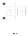
図3はデンタルフロッサの残りの部分から分離されたスライド部材16の断面図である。簡略化のため、フロス束は図3に示されていない。スライド部材16の一端が雌部材を備え、当該スライド部材の他端が対応する寸法を有する雄部材を備え、スライド部材が折り畳まれたときに雄部材が雌部材に嵌合することができる。
Figure 3 is a cross-sectional view of
図4は、図3のスライド部材の断面図であって、雄部材を雌部材に接続させるように、当該スライド部材が折り畳まれている。折り畳まれたスライド部材16は、ユーザの親指または他の指によってより持ちやすくて操作しやすい。
Figure 4 is a cross-sectional view of the slide member of Figure 3, with the slide member folded to connect the male member to the female member. The folded
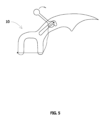
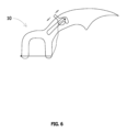
図5は、折り畳まれたスライド部材16がデンタルフロッサ10の溝28に嵌合されたデンタルフロッサ10を示す。図6は折り畳まれたスライド部材16を示し、よって、ユーザはスライド部材16をより持ちやすくて操作しやすい。
Figure 5 shows the
図7は、フロス束26の張力を増加するように、スライド部材16が溝28に沿って第1方向に移動することを示す。図7において、アーム22とアーム24との間のフロス束26は、張力がかかった状態では直線状である。フロス束26の張力がかかった状態で、ユーザは、デンタルフロッサ10を下方へ押して、隣接する2つの歯の間の歯間空間内にフロス束26を挿入することができる。
FIG. 7 shows the sliding
図8は、フロス束26の張力を減少するように、スライド部材16が溝28に沿って第2方向に移動することを示す。図8において、アーム22とアーム24との間のフロス束26は、緩んで、増加された長さを有する。ユーザは、デンタルフロッサ10を横向きに操作し、フロス束26を歯の輪郭の周りで曲げる。
FIG. 8 shows the sliding
理解されるべきことに、デンタルフロッサ10に提供されたフロス束26の全長は固定的なものである。フロス束26は製造プロセスにおいてデンタルフロッサ10にすでに固定される。ユーザはフロス束26をデンタルフロッサ10に装着するまたは張る必要がない。しかしながら、ユーザは、スライド部材16を操作して、フロス束26においてアーム22とアーム24との間の部分の長さ(および張力)を調整することができる。
It should be understood that the overall length of the
図9は、隣接する2つの歯、および、これらの歯の間の歯間空間内において張力がかかったデンタル束の位置を示す概略上面図である。図10は、隣接する2つの歯、ならびに、歯の歯間空間、前面、および後面を囲む、緩んだデンタル束の位置を示す概略上面図である。 Figure 9 is a schematic top view showing two adjacent teeth and the position of a tensioned dental bundle in the interdental space between the teeth. Figure 10 is a schematic top view showing two adjacent teeth and the position of a relaxed dental bundle surrounding the interdental space, anterior and posterior surfaces of the teeth.
典型的なデンタルフロッサと比べて、デンタルフロッサ10は複数の方面で有利である。1つ目は、デンタルフロッサ10は1つ歯の3つの表面(歯間表面、前面、および後面)を同時に清浄するように使用可能なことである。2つ目は、ユーザはフロス束の張力を任意に調整することができることである。フロス束の一端がアーム22に固定されて動かないため、ユーザは、スライド部材16に取り付けられたフロス束の他端のみを移動させる必要があるのみである。3つ目は、ユーザは、異なるサイズおよび寸法を有する歯に適合するように、アーム22とアーム24との間のフロス束の長さを調整できることである。4つ目は、デンタルフロッサ10が、フロス束と、取り外したまたは取り外し可能なスライド部材部と含む一体成形の製品として、射出成形プロセスにおいて便利に製造されることである。5つ目は、デンタルフロッサ10の製造のための材料の量は、典型的なデンタルフロッサの製造のための材料の量よりはあまり多くないことである。スライド部材が小さい要素であるため、デンタルフロッサ10の製造のための材料の量をあまり増やさない。射出成形設備はデンタルフロッサ10の製造に利用可能または適用可能である。デンタルフロッサ10の製造には、専用の設備または機械または組み立てを必要としない。6つ目は、デンタルフロッサ10は、使い捨て製品として販売可能であり、特定の顧客に対してより便利性を提供できることである。7つ目は、フロス束26がデンタルフロッサ10に常に固く固定されるため、ユーザは、フロス束26が間違えてデンタルフロッサ10から分離すると心配する必要がないことである。
Compared to a typical dental flosser, the
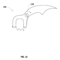
図11から図13は、本発明の別の例示的な実施例に係るデンタルフロッサ100を示す。デンタルフロッサ100は、U形部112と、手持ち部114と、フロス束取り付け構造116とを備える。U形部112は、ベース120と、ベース120から延びて離間された一対のアーム(第1アーム122および第2アーム124)とを備える。デンタルフロッサ100はフロス束126を備える。フロス束100は、U形部112の第1アーム122に固定的に取り付けられた第1末端を有する。フロス束126の第1末端の位置は、U形部112の第1アーム122に対して移動しない。図11から図13に示されているように、フロス束126の第1末端は第1アーム122の端部に固定的に取り付けられる。フロス束100は、フロス束取り付け構造116に固定的に取り付けられた第2末端を有する。図11から図13に示されているように、フロス束取り付け構造116は、手持ち部114から分離可能でありながら、手持ち部114における回転機構128に接続可能である。ユーザは、フロス束の張力を増加する、減少する、または維持するように、手動的に(または機械的にまたは電気的に)フロス束取り付け構造116を操作し、フロス束126の第2末端を移動させてもよい。
11-13 show a
フロス束126の中間部はU形部112の第2アーム124にスライド可能に装着され、よって、フロス束の中間部はU形部112の第2アーム124に対してスライド可能である。フロス束の中間部をU形部の第2アームにスライド可能に装着させるために、いくつかの装着機構は適用され得て、例えば、固定滑車、枢軸、輪、ロータ、チャネル、通路、穴、または他の適した手段は適用され得る。図11に示された例示において、装着機構は、U形部112の第2アーム124の端部にあるチャネル、またはU形部112の第2アーム124の端部の近傍にあるチャネルである。フロス束126の中間部は第2アーム124におけるチャネルをスライドすることができる。
The middle portion of the
デンタルフロッサ100は回転機構128を備える。回転機構は、手動的、機械的または電気的な回転機構であってもよい。図12および図13に示されているように、ユーザはフロス束取り付け構造116を回転機構128に取り付けてもよい。取り付けると、ユーザは、フロス束126の張力を増加するように、回転機構128を1つの方向(例えば、反時計回り)に回転させてもよい。また、ユーザは、フロス束126の張力を減少するように、回転機構128をもう1つの方向(例えば、時計回り)に回転させてもよい。必要がある場合、ユーザは、回転機構128からフロス束取り付け構造116を外してもよい。図14は使用可能な例示的な回転機構128の拡大断面図を示す。回転機構128は、フロス束取り付け構造116を受けるための凹み130と、フロス束126を巻くための環状溝132とを備える。
The
前述した説明に照らして本分野の当業者にとって明らかであるように、本発明の実施において多くの代替例および変化例が可能である。特許請求の範囲は、例示に記載された好ましい実施形態によって限定されるべきではなく、全体としての説明と一致する、最も広い解釈をとるべきである。 As will be apparent to those skilled in the art in light of the foregoing description, many alterations and variations are possible in the practice of this invention. The scope of the claims should not be limited by the preferred embodiments set forth in the examples, but should be accorded the broadest interpretation consistent with the description as a whole.
Claims (18)
前記手持ち部は溝を含み、
前記フロス束取り付け部材は、前記フロス束の張力を増加するまたは減少するように、前記溝に受けられて前記溝に沿ってスライド可能であり、前記フロス束取り付け部材は両端を有し、前記フロス束取り付け部材の一端は雌部材を含み、前記フロス束取り付け部材の他端は雄部材を含み、前記フロス束取り付け部材は、前記雄部材を前記雌部材に接続させるように、折り畳み可能である、デンタルフロッサ。 A dental flosser comprising: a U-shaped portion having first and second arms spaced apart from one another; a handle extending from the U-shaped portion; a floss bundle having a length and a first and second end; and a floss bundle attachment member, the first end of the floss bundle being secured to and embedded in the first arm of the U-shaped portion, the second end of the floss bundle being secured to the floss bundle attachment member, and an intermediate portion of the floss bundle being slidably mounted to the second arm of the U-shaped portion, the floss bundle attachment member being operable by a user to increase, decrease or maintain tension in the floss bundle;
the handle portion includes a groove ;
A dental flosser, wherein the floss bundle attachment member is received in and slidable along the groove to increase or decrease tension on the floss bundle, the floss bundle attachment member has opposite ends, one end of the floss bundle attachment member includes a female member and the other end of the floss bundle attachment member includes a male member, and the floss bundle attachment member is foldable to connect the male member to the female member .
Applications Claiming Priority (3)
| Application Number | Priority Date | Filing Date | Title |
|---|---|---|---|
| US16/545,739 | 2019-08-20 | ||
| US16/545,739 US11963834B2 (en) | 2019-08-20 | 2019-08-20 | Dental flosser with means for adjusting floss tension |
| PCT/CA2020/051105 WO2021030901A1 (en) | 2019-08-20 | 2020-08-12 | Dental flosser with means for adjusting floss tension |
Publications (2)
| Publication Number | Publication Date |
|---|---|
| JP2022545885A JP2022545885A (en) | 2022-11-01 |
| JP7635207B2 true JP7635207B2 (en) | 2025-02-25 |
Family
ID=74647491
Family Applications (1)
| Application Number | Title | Priority Date | Filing Date |
|---|---|---|---|
| JP2022511263A Active JP7635207B2 (en) | 2019-08-20 | 2020-08-12 | Dental flosser having means for adjusting floss tension - Patents.com |
Country Status (6)
| Country | Link |
|---|---|
| US (1) | US11963834B2 (en) |
| EP (1) | EP4017403A4 (en) |
| JP (1) | JP7635207B2 (en) |
| CN (1) | CN114302694A (en) |
| AU (1) | AU2020334394B2 (en) |
| WO (1) | WO2021030901A1 (en) |
Families Citing this family (4)
| Publication number | Priority date | Publication date | Assignee | Title |
|---|---|---|---|---|
| US20220241057A1 (en) * | 2021-02-03 | 2022-08-04 | Terry Joldersma | Dental apparatus and method of using the same |
| US11284977B1 (en) * | 2021-06-22 | 2022-03-29 | Vincent Paul Jalbert | Adjustable dental-floss apparatus |
| US12220290B2 (en) * | 2022-03-24 | 2025-02-11 | Vincent Paul Jalbert | Flossing apparatus with quick release |
| US12257111B1 (en) * | 2024-04-17 | 2025-03-25 | Meng Xu | Dental flosser with collar member for adjusting floss tension |
Citations (6)
| Publication number | Priority date | Publication date | Assignee | Title |
|---|---|---|---|---|
| JP2002143189A (en) | 2000-11-07 | 2002-05-21 | Takeshi Kamiezu | Simple interdental cleaner |
| JP2002535072A (en) | 1999-01-26 | 2002-10-22 | ジオヴァンニ サントロ | Motor-driven device that mechanically cleans the interdental space with dental floss |
| JP2014138855A (en) | 2013-01-17 | 2014-07-31 | Geefloss Corp | Interdental cleaning tool |
| US20160067021A1 (en) | 2013-04-16 | 2016-03-10 | Trisa Holding Ag | Flosser |
| JP2018064752A (en) | 2016-10-19 | 2018-04-26 | 昭安 宮澤 | Electric interdental cleaning holder |
| WO2018110738A1 (en) | 2016-12-14 | 2018-06-21 | 오봉균 | Dental floss member and dental floss holder |
Family Cites Families (33)
| Publication number | Priority date | Publication date | Assignee | Title |
|---|---|---|---|---|
| DE321203C (en) * | 1919-05-09 | 1920-05-26 | Franz Stark | Clothes fastener with a button that can be moved in a guide slot provided with notches |
| US1512633A (en) | 1923-11-15 | 1924-10-21 | John A Peckham | Dental floss holder |
| US1507216A (en) * | 1923-11-21 | 1924-09-02 | George C Thomas | Fastener |
| GB778564A (en) * | 1955-03-17 | 1957-07-10 | Borgtor Gjerde | Tooth cleaning device |
| US3236247A (en) | 1963-12-11 | 1966-02-22 | Brockman Leonard | Dental string or floss holder with means for adjusting string or floss tension |
| US3993085A (en) | 1975-06-23 | 1975-11-23 | Skinner Edward T | Dental floss applicator |
| US4151851A (en) * | 1976-05-27 | 1979-05-01 | Bragg Kenneth R | Dental flossing tool |
| AU508117B3 (en) * | 1979-11-06 | 1980-03-06 | A. Radici | Composite tooth brush and dental tool |
| US4655233A (en) * | 1985-11-04 | 1987-04-07 | Laughlin Patrick E | Dental flossing tool |
| US4807651A (en) * | 1985-12-23 | 1989-02-28 | Abram Naydich | Dental debris remover |
| US4832062A (en) * | 1988-01-19 | 1989-05-23 | Grollimund Everett C | Dual flosser |
| EP0339935B1 (en) * | 1988-04-26 | 1994-01-05 | Mitsui Petrochemical Industries, Ltd. | Dental floss and interdental cleaning tool |
| US5183064A (en) * | 1988-12-19 | 1993-02-02 | Frederic Barth | Dental cleansing device and interdental floss for such a device |
| ES2159515T3 (en) * | 1988-12-19 | 2001-10-16 | Frederic Barth | INTERDENTAL CLEANING DEVICE WITH CORRESPONDING THREAD. |
| US5139038A (en) | 1991-03-28 | 1992-08-18 | El Gazayerli Mohamed M | Dental flossing instrument |
| JPH0513414U (en) * | 1991-08-07 | 1993-02-23 | ライオン株式会社 | Tooth cleaning tool |
| US5305768A (en) * | 1992-08-24 | 1994-04-26 | Product Development (Zgs) Ltd. | Dental flosser units and method of making same |
| GB2272161A (en) * | 1992-11-04 | 1994-05-11 | Danny Thomas Homewood | Dental floss applicator |
| US5280797A (en) * | 1993-01-25 | 1994-01-25 | Stephen Fry | Dental floss tool |
| CN1101819A (en) * | 1993-10-20 | 1995-04-26 | B·A·L国际(财产)有限公司 | Adjustable fasteners for waist bnads |
| JPH10295414A (en) * | 1997-05-02 | 1998-11-10 | Ykk Corp | Male and female buttons |
| US6155274A (en) * | 1998-08-20 | 2000-12-05 | Stein; Peter | Floss stretcher arm |
| JP2002165615A (en) * | 2000-11-30 | 2002-06-11 | Ykk Corp | Snap fastener |
| DE10125482B4 (en) * | 2001-05-25 | 2004-09-30 | Hubert Dr. Staerk | Dental floss holder |
| JP4971989B2 (en) | 2004-11-24 | 2012-07-11 | ベリフレッシュ リミテッド | Ergonomic dental floss tool |
| US10806551B2 (en) * | 2010-09-20 | 2020-10-20 | Roman Kozak | Dental tape and floss holder with installation cassette |
| US20120180809A1 (en) * | 2011-01-17 | 2012-07-19 | Mingwu Bai | Easy dental flossing device and flossing method |
| US8424544B2 (en) * | 2011-05-04 | 2013-04-23 | Abdulrahman Alas | Toothpick with floss |
| US20150059791A1 (en) * | 2013-09-05 | 2015-03-05 | Russell M. Sheppel | Floss type cleaning device |
| CN204814248U (en) * | 2015-07-24 | 2015-12-02 | 谢莹莹 | Dental floss elasticity adjustable dental floss frame |
| TWI599518B (en) * | 2016-09-09 | 2017-09-21 | Chen-Cheng Huang | Chain belt |
| KR101706973B1 (en) * | 2016-10-12 | 2017-02-15 | 김상한 | Dental Floss Holder which can control the tention |
| CN109091258A (en) * | 2018-10-15 | 2018-12-28 | 浦江县益芽优日用品有限公司 | A kind of toothbrush for tooth proximal surface |
-
2019
- 2019-08-20 US US16/545,739 patent/US11963834B2/en active Active
-
2020
- 2020-08-12 EP EP20855564.9A patent/EP4017403A4/en active Pending
- 2020-08-12 JP JP2022511263A patent/JP7635207B2/en active Active
- 2020-08-12 CN CN202080058762.0A patent/CN114302694A/en active Pending
- 2020-08-12 AU AU2020334394A patent/AU2020334394B2/en active Active
- 2020-08-12 WO PCT/CA2020/051105 patent/WO2021030901A1/en not_active Ceased
Patent Citations (6)
| Publication number | Priority date | Publication date | Assignee | Title |
|---|---|---|---|---|
| JP2002535072A (en) | 1999-01-26 | 2002-10-22 | ジオヴァンニ サントロ | Motor-driven device that mechanically cleans the interdental space with dental floss |
| JP2002143189A (en) | 2000-11-07 | 2002-05-21 | Takeshi Kamiezu | Simple interdental cleaner |
| JP2014138855A (en) | 2013-01-17 | 2014-07-31 | Geefloss Corp | Interdental cleaning tool |
| US20160067021A1 (en) | 2013-04-16 | 2016-03-10 | Trisa Holding Ag | Flosser |
| JP2018064752A (en) | 2016-10-19 | 2018-04-26 | 昭安 宮澤 | Electric interdental cleaning holder |
| WO2018110738A1 (en) | 2016-12-14 | 2018-06-21 | 오봉균 | Dental floss member and dental floss holder |
Also Published As
| Publication number | Publication date |
|---|---|
| EP4017403A4 (en) | 2023-08-16 |
| CA3144554A1 (en) | 2021-02-25 |
| US11963834B2 (en) | 2024-04-23 |
| AU2020334394A1 (en) | 2022-03-31 |
| WO2021030901A1 (en) | 2021-02-25 |
| AU2020334394B2 (en) | 2026-01-22 |
| JP2022545885A (en) | 2022-11-01 |
| CN114302694A (en) | 2022-04-08 |
| US20210052357A1 (en) | 2021-02-25 |
| KR20220049510A (en) | 2022-04-21 |
| EP4017403A1 (en) | 2022-06-29 |
Similar Documents
| Publication | Publication Date | Title |
|---|---|---|
| JP7635207B2 (en) | Dental flosser having means for adjusting floss tension - Patents.com | |
| US4014354A (en) | Dental flossing tool | |
| US8631807B2 (en) | Method and apparatus for orthodontic floss aid | |
| JP4971989B2 (en) | Ergonomic dental floss tool | |
| EP2324796A1 (en) | Dental interproximal cleaning device | |
| JP7731298B2 (en) | Interdental cleaning tools | |
| US6973933B2 (en) | Flosser apparatus with detachable and positionable floss element | |
| KR102938022B1 (en) | Dental flosser with floss tension control | |
| US20240415620A1 (en) | Dental flosser assembly with disposable portion and means for adjusting floss tension and method of use | |
| US11504215B2 (en) | Disposable flosser head attachment for a water floss pick | |
| CA3144554C (en) | Dental flosser with means for adjusting floss tension | |
| JP2026047160A (en) | Dental flosser assembly having a disposable part and means for adjusting floss tension | |
| KR102436488B1 (en) | Holder for dental floss | |
| US20120285478A1 (en) | Disposable Flosser | |
| US20090151746A1 (en) | Cleaning apparatus for dental flossing | |
| US12257111B1 (en) | Dental flosser with collar member for adjusting floss tension | |
| US20240293208A1 (en) | Dental flosser with opposing prong members for securing floss | |
| EP4706591A1 (en) | Dental flosser assembly with disposable portion and means for adjusting floss tension | |
| KR102583463B1 (en) | Apparatus for cleaning teeth | |
| US20240293207A1 (en) | Flossing Device and Methodology | |
| US20240261072A1 (en) | Dental flosser with rotation mechanism for adjusting floss tension | |
| US20090007930A1 (en) | Dental flossing device and its fabrication and use | |
| JP2533445B2 (en) | Toothbrush and electric toothbrush | |
| CN119033486A (en) | Dental floss device with tension adjusting device | |
| CN114502097A (en) | Interdental cleaning device |
Legal Events
| Date | Code | Title | Description |
|---|---|---|---|
| A621 | Written request for application examination |
Free format text: JAPANESE INTERMEDIATE CODE: A621 Effective date: 20230712 |
|
| A131 | Notification of reasons for refusal |
Free format text: JAPANESE INTERMEDIATE CODE: A131 Effective date: 20240305 |
|
| A521 | Request for written amendment filed |
Free format text: JAPANESE INTERMEDIATE CODE: A523 Effective date: 20240530 |
|
| A02 | Decision of refusal |
Free format text: JAPANESE INTERMEDIATE CODE: A02 Effective date: 20240903 |
|
| A521 | Request for written amendment filed |
Free format text: JAPANESE INTERMEDIATE CODE: A523 Effective date: 20241202 |
|
| A521 | Request for written amendment filed |
Free format text: JAPANESE INTERMEDIATE CODE: A821 Effective date: 20241202 |
|
| A911 | Transfer to examiner for re-examination before appeal (zenchi) |
Free format text: JAPANESE INTERMEDIATE CODE: A911 Effective date: 20241219 |
|
| TRDD | Decision of grant or rejection written | ||
| A01 | Written decision to grant a patent or to grant a registration (utility model) |
Free format text: JAPANESE INTERMEDIATE CODE: A01 Effective date: 20250204 |
|
| A61 | First payment of annual fees (during grant procedure) |
Free format text: JAPANESE INTERMEDIATE CODE: A61 Effective date: 20250212 |
|
| R150 | Certificate of patent or registration of utility model |
Ref document number: 7635207 Country of ref document: JP Free format text: JAPANESE INTERMEDIATE CODE: R150 |