JP7635200B2 - Control device, inverter, assembly with inverter and electric machine, method for operating inverter and computer program - Patents.com - Google Patents
Control device, inverter, assembly with inverter and electric machine, method for operating inverter and computer program - Patents.com Download PDFInfo
- Publication number
- JP7635200B2 JP7635200B2 JP2022506203A JP2022506203A JP7635200B2 JP 7635200 B2 JP7635200 B2 JP 7635200B2 JP 2022506203 A JP2022506203 A JP 2022506203A JP 2022506203 A JP2022506203 A JP 2022506203A JP 7635200 B2 JP7635200 B2 JP 7635200B2
- Authority
- JP
- Japan
- Prior art keywords
- rotational speed
- torque
- operating
- operating region
- carrier frequency
- Prior art date
- Legal status (The legal status is an assumption and is not a legal conclusion. Google has not performed a legal analysis and makes no representation as to the accuracy of the status listed.)
- Active
Links
Images


Classifications
-
- H—ELECTRICITY
- H02—GENERATION; CONVERSION OR DISTRIBUTION OF ELECTRIC POWER
- H02P—CONTROL OR REGULATION OF ELECTRIC MOTORS, ELECTRIC GENERATORS OR DYNAMO-ELECTRIC CONVERTERS; CONTROLLING TRANSFORMERS, REACTORS OR CHOKE COILS
- H02P23/00—Arrangements or methods for the control of AC motors characterised by a control method other than vector control
- H02P23/04—Arrangements or methods for the control of AC motors characterised by a control method other than vector control specially adapted for damping motor oscillations, e.g. for reducing hunting
-
- H—ELECTRICITY
- H02—GENERATION; CONVERSION OR DISTRIBUTION OF ELECTRIC POWER
- H02M—APPARATUS FOR CONVERSION BETWEEN AC AND AC, BETWEEN AC AND DC, OR BETWEEN DC AND DC, AND FOR USE WITH MAINS OR SIMILAR POWER SUPPLY SYSTEMS; CONVERSION OF DC OR AC INPUT POWER INTO SURGE OUTPUT POWER; CONTROL OR REGULATION THEREOF
- H02M7/00—Conversion of AC power input into DC power output; Conversion of DC power input into AC power output
- H02M7/42—Conversion of DC power input into AC power output without possibility of reversal
- H02M7/44—Conversion of DC power input into AC power output without possibility of reversal by static converters
- H02M7/48—Conversion of DC power input into AC power output without possibility of reversal by static converters using discharge tubes with control electrode or semiconductor devices with control electrode
- H02M7/53—Conversion of DC power input into AC power output without possibility of reversal by static converters using discharge tubes with control electrode or semiconductor devices with control electrode using devices of a triode or transistor type requiring continuous application of a control signal
- H02M7/537—Conversion of DC power input into AC power output without possibility of reversal by static converters using discharge tubes with control electrode or semiconductor devices with control electrode using devices of a triode or transistor type requiring continuous application of a control signal using semiconductor devices only, e.g. single switched pulse inverters
- H02M7/5387—Conversion of DC power input into AC power output without possibility of reversal by static converters using discharge tubes with control electrode or semiconductor devices with control electrode using devices of a triode or transistor type requiring continuous application of a control signal using semiconductor devices only, e.g. single switched pulse inverters in a bridge configuration
-
- H—ELECTRICITY
- H02—GENERATION; CONVERSION OR DISTRIBUTION OF ELECTRIC POWER
- H02M—APPARATUS FOR CONVERSION BETWEEN AC AND AC, BETWEEN AC AND DC, OR BETWEEN DC AND DC, AND FOR USE WITH MAINS OR SIMILAR POWER SUPPLY SYSTEMS; CONVERSION OF DC OR AC INPUT POWER INTO SURGE OUTPUT POWER; CONTROL OR REGULATION THEREOF
- H02M7/00—Conversion of AC power input into DC power output; Conversion of DC power input into AC power output
- H02M7/42—Conversion of DC power input into AC power output without possibility of reversal
- H02M7/44—Conversion of DC power input into AC power output without possibility of reversal by static converters
- H02M7/48—Conversion of DC power input into AC power output without possibility of reversal by static converters using discharge tubes with control electrode or semiconductor devices with control electrode
- H02M7/53—Conversion of DC power input into AC power output without possibility of reversal by static converters using discharge tubes with control electrode or semiconductor devices with control electrode using devices of a triode or transistor type requiring continuous application of a control signal
- H02M7/537—Conversion of DC power input into AC power output without possibility of reversal by static converters using discharge tubes with control electrode or semiconductor devices with control electrode using devices of a triode or transistor type requiring continuous application of a control signal using semiconductor devices only, e.g. single switched pulse inverters
- H02M7/539—Conversion of DC power input into AC power output without possibility of reversal by static converters using discharge tubes with control electrode or semiconductor devices with control electrode using devices of a triode or transistor type requiring continuous application of a control signal using semiconductor devices only, e.g. single switched pulse inverters with automatic control of output wave form or frequency
- H02M7/5395—Conversion of DC power input into AC power output without possibility of reversal by static converters using discharge tubes with control electrode or semiconductor devices with control electrode using devices of a triode or transistor type requiring continuous application of a control signal using semiconductor devices only, e.g. single switched pulse inverters with automatic control of output wave form or frequency by pulse-width modulation
-
- H—ELECTRICITY
- H02—GENERATION; CONVERSION OR DISTRIBUTION OF ELECTRIC POWER
- H02P—CONTROL OR REGULATION OF ELECTRIC MOTORS, ELECTRIC GENERATORS OR DYNAMO-ELECTRIC CONVERTERS; CONTROLLING TRANSFORMERS, REACTORS OR CHOKE COILS
- H02P21/00—Arrangements or methods for the control of electric machines by vector control, e.g. by control of field orientation
- H02P21/0085—Arrangements or methods for the control of electric machines by vector control, e.g. by control of field orientation specially adapted for high speeds, e.g. above nominal speed
- H02P21/0089—Arrangements or methods for the control of electric machines by vector control, e.g. by control of field orientation specially adapted for high speeds, e.g. above nominal speed using field weakening
-
- H—ELECTRICITY
- H02—GENERATION; CONVERSION OR DISTRIBUTION OF ELECTRIC POWER
- H02P—CONTROL OR REGULATION OF ELECTRIC MOTORS, ELECTRIC GENERATORS OR DYNAMO-ELECTRIC CONVERTERS; CONTROLLING TRANSFORMERS, REACTORS OR CHOKE COILS
- H02P27/00—Arrangements or methods for the control of AC motors characterised by the kind of supply voltage
- H02P27/04—Arrangements or methods for the control of AC motors characterised by the kind of supply voltage using variable-frequency supply voltage, e.g. inverter or converter supply voltage
- H02P27/06—Arrangements or methods for the control of AC motors characterised by the kind of supply voltage using variable-frequency supply voltage, e.g. inverter or converter supply voltage using DC to AC converters or inverters
- H02P27/08—Arrangements or methods for the control of AC motors characterised by the kind of supply voltage using variable-frequency supply voltage, e.g. inverter or converter supply voltage using DC to AC converters or inverters with pulse width modulation
- H02P27/085—Arrangements or methods for the control of AC motors characterised by the kind of supply voltage using variable-frequency supply voltage, e.g. inverter or converter supply voltage using DC to AC converters or inverters with pulse width modulation wherein the PWM mode is adapted on the running conditions of the motor, e.g. the switching frequency
-
- H—ELECTRICITY
- H02—GENERATION; CONVERSION OR DISTRIBUTION OF ELECTRIC POWER
- H02P—CONTROL OR REGULATION OF ELECTRIC MOTORS, ELECTRIC GENERATORS OR DYNAMO-ELECTRIC CONVERTERS; CONTROLLING TRANSFORMERS, REACTORS OR CHOKE COILS
- H02P29/00—Arrangements for regulating or controlling electric motors, appropriate for both AC and DC motors
- H02P29/50—Reduction of harmonics
Landscapes
- Engineering & Computer Science (AREA)
- Power Engineering (AREA)
- Control Of Ac Motors In General (AREA)
- Inverter Devices (AREA)
Description
本発明は、電気機械に給電するインバータのための制御装置であって、インバータのスイッチング素子を駆動するための搬送周波数を有するパルス幅変調スイッチング信号を提供するように構成された制御装置に関する。 The present invention relates to a control device for an inverter that powers an electric machine, the control device being configured to provide a pulse-width modulated switching signal having a carrier frequency for driving switching elements of the inverter.
本発明はさらに、インバータ、インバータおよび電気機械を有するアセンブリ、インバータおよびコンピュータプログラムを動作させるための方法に関する。 The invention further relates to an inverter, an assembly having an inverter and an electric machine, an inverter and a method for operating a computer program.
電動ビークルの重要性の高まりにより、そのような応用分野のためのインバータおよびインバータ関連の制御装置が、産業開発努力の焦点になっている。インバータのスイッチング素子を駆動するための一定の搬送周波数を有するパルス幅変調スイッチング信号を提供するタイプの制御装置は公知である。 Due to the growing importance of electric vehicles, inverters and inverter-related controllers for such applications have become the focus of industry development efforts. Controllers of the type that provide pulse-width modulated switching signals having a constant carrier frequency for driving the switching elements of the inverter are known.
パルス出力電圧は、そのようなスイッチング動作の状況で発生し、特に低トルクの特定の領域では、電気機械の相電流の高い全高調波歪み(THD)をもたらす可能性がある。しかしながら、結果として、電気機械に望ましくない機械的振動が発生することになる。 Pulse output voltages occur in such switching situations and can result in high total harmonic distortion (THD) of the phase currents of the electric machine, especially in certain regions of low torque. However, the result is undesirable mechanical vibrations in the electric machine.
したがって、本発明は、インバータの動作における高調波歪みを低減させるという目的に基づくものである。 The present invention is therefore based on the objective of reducing harmonic distortion in the operation of an inverter.
この目的は、本発明によれば、電気機械の回転速度およびトルクによって定義される動作点を記述する動作点情報に依存して搬送周波数を決定し、回転速度が増加し、トルクの大きさが減少するに従い、下限回転速度がゼロとは異なり、上限回転速度が電力制限動作領域または弱め界磁動作領域にある回転速度間隔内に広がる動作領域内で搬送周波数を増加させるように構成された、最初に述べたタイプの制御装置によって達成される。 This object is achieved according to the invention by a control device of the first mentioned type, configured to determine the carrier frequency depending on operating point information describing an operating point defined by the rotational speed and torque of the electric machine, and to increase the carrier frequency as the rotational speed increases and the magnitude of the torque decreases within an operating region whose lower limit rotational speed is different to zero and whose upper limit rotational speed extends within a rotational speed interval that is in the power-limited operating region or in the field-weakening operating region.
本発明は、インバータの出力電圧の全高調波歪みが、一方では、増加すると全高調波歪みを減少させる搬送周波数に依存し、他方では、電気機械の動作点に依存する、という認識に基づくものである。(第1の)動作領域では、搬送周波数が一定のままであると仮定される場合には、トルクの大きさに応じて、低いスイッチング損失のみがそれでもなお生じるが、しかしながら、回転速度が上昇し、トルクの大きさが減少するに従い、全高調波歪みの増加が進む。したがって、全高調波歪みを低減または制限するために、一定の搬送周波数で動作する場合と比較して、より高いスイッチング損失を許容することができるため、搬送周波数の増加の余地がある。よって有利には、全高調波歪み、ひいては望ましくない機械的振動が低減される。 The invention is based on the recognition that the total harmonic distortion of the inverter output voltage depends on the carrier frequency, which, when increased, reduces the total harmonic distortion, on the one hand, and on the operating point of the electric machine, on the other hand. In the (first) operating region, if the carrier frequency is assumed to remain constant, only low switching losses still occur depending on the magnitude of the torque, but as the rotation speed increases and the magnitude of the torque decreases, the total harmonic distortion increases. Therefore, in order to reduce or limit the total harmonic distortion, there is room for an increase in the carrier frequency, since higher switching losses can be tolerated compared to operating with a constant carrier frequency. Thus, advantageously, the total harmonic distortion and therefore the undesirable mechanical vibrations are reduced.
出力電圧の全高調波歪みは、典型的には、本発明の目的では、インバータの出力電圧の周波数成分の重み付き組み合わせである歪み尺度によって記述される。一般的には、そのような歪み尺度mTHDは、以下の式で表すことができる。
式中、NACは、電気機械の電気周波数fACとインバータの出力電圧uxの基本周波数ffとの比を表し、anは、重み係数である。時間tの関数としての出力電圧は、以下の式によって記述される。
3つの出力位相を有するインバータの特に実際的に関連する事例では、x∈{RS,ST,TR}が、通常の位相識別子R、SおよびTに関連して設定されることになる。 In the particularly practically relevant case of an inverter with three output phases, x∈{RS,ST,TR} would be set in relation to the usual phase identifiers R, S and T.
本発明がそれに限定されない歪み尺度mTHDの可能な特殊事例として、重み付き全高調波歪み(WTHD)は、周波数成分がそれらの順序に従って重み付けされるものとみなされるべきである。その場合、
本発明による制御装置の場合には、下限回転速度が基本回転速度動作領域にあることが好ましい。 In the case of a control device according to the present invention, it is preferable that the lower limit rotational speed is in the basic rotational speed operating range.
有利には、本発明による制御装置に関して、動作領域の第1の境界は、その回転速度が下限回転速度に対応する第1の動作点から、その回転速度が下限回転速度よりも大きく、そのトルクの大きさが第1の動作点のトルクの大きさよりも大きい第2の動作点まで延びるものとすることができる。代替的または追加的に、動作領域の第2の境界は、その回転速度が上限回転速度に対応する第1の動作点から、その回転速度が上限回転速度よりも低く、そのトルクの大きさが第1の動作点のトルクの大きさよりも大きい第2の動作点まで延びるものとすることもできる。 Advantageously, for a control device according to the invention, the first boundary of the operating range can extend from a first operating point, the rotational speed of which corresponds to a lower limit rotational speed, to a second operating point, the rotational speed of which is greater than the lower limit rotational speed and the magnitude of the torque of which is greater than the magnitude of the torque of the first operating point. Alternatively or additionally, the second boundary of the operating range can extend from a first operating point, the rotational speed of which corresponds to an upper limit rotational speed, to a second operating point, the rotational speed of which is lower than the upper limit rotational speed and the magnitude of the torque of which is greater than the magnitude of the torque of the first operating point.
特に、制御装置が、連続パルス幅変調、特に空間ベクトル変調によってパルス幅変調スイッチング信号を生成するように構成されるものとすることができる、本発明の第1の好ましい実施形態を以下で説明する。 In particular, a first preferred embodiment of the invention is described below in which the control device may be configured to generate a pulse width modulated switching signal by continuous pulse width modulation, in particular space vector modulation.
第1の好ましい実施形態では、第1の境界と第2の境界との第2の動作点は、同一であり、かつ/または電力制限動作領域もしくは弱め界磁動作領域にあり、かつ/またはそれぞれの動作点の回転速度におけるトルクの最大の大きさから離れているものとすることができる。 In a first preferred embodiment, the second operating points of the first and second boundaries may be the same and/or may be in a power-limited or field-weakening operating region and/or may be away from the maximum magnitude of the torque at the rotational speed of the respective operating point.
さらに、第1の好ましい実施形態では、制御装置は、それぞれの回転速度におけるそのトルクの大きさが、この回転速度における第1の動作領域でのトルクの最大の大きさよりも大きい動作点を含む、第1の動作領域と重ならずに定義された第2の動作領域内で、特にトルクとは無関係に、回転速度の上昇に伴って搬送周波数を増加させるように構成されるものとすることができる。搬送周波数値が都合よく、第1の動作領域の搬送周波数値に途切れずに隣接している第2の動作領域におけるトルクの全高調波歪みに対する影響は、あるとしても非常に小さいことが確認されている。この点において、第2の動作領域の定義は、全高調波歪みの低減を、電気機械のより高い負荷の動作点、特に全負荷動作まで拡張することを可能にする。この場合の全負荷動作は、本発明の文脈では一般に、それぞれの回転速度に対するトルクの最大の大きさを有する動作点を含む動作モードとして理解することができる。 Furthermore, in the first preferred embodiment, the control device may be configured to increase the carrier frequency with increasing rotational speed, in particular independently of the torque, within a second operating range defined without overlapping with the first operating range, which includes an operating point whose torque magnitude at the respective rotational speed is greater than the maximum torque magnitude in the first operating range at this rotational speed. It has been determined that the effect on the total harmonic distortion of the torque in the second operating range, whose carrier frequency value is advantageously adjacent to the carrier frequency value of the first operating range without interruption, is very small, if at all. In this respect, the definition of the second operating range allows the reduction of the total harmonic distortion to be extended up to operating points of higher loads of the electric machine, in particular full load operation. Full load operation in this case can be generally understood in the context of the present invention as an operating mode including an operating point with a maximum torque magnitude for the respective rotational speed.
したがって、第2の動作領域は、完全に電力制限動作領域もしくは弱め界磁動作領域内に位置し、かつ/または最大全負荷動作まで及ぶものとすることができる。 Thus, the second operating region may be entirely within the power-limited or field-weakening operating region and/or extend up to maximum full-load operation.
特に、制御装置が、不連続パルス幅変調、特に一般化された不連続パルス幅変調(GDPWM)によってパルス幅変調スイッチング信号を生成するように構成されるものとすることができる、本発明の第2の好ましい実施形態を以下で説明する。 In particular, a second preferred embodiment of the present invention is described below in which the control device may be configured to generate a pulse width modulated switching signal by discontinuous pulse width modulation, in particular generalized discontinuous pulse width modulation (GDPWM).
第2の好ましい実施形態では、制御装置が、それぞれの回転速度におけるそのトルクの大きさが、この回転速度における第1の動作領域でのトルクの最大の大きさよりも大きい動作点を含む、第1の動作領域と重ならずに定義された第2の動作領域内で、回転速度の減少およびトルクの減少に伴って搬送周波数を増加させるように構成されれば有利である。 In a second preferred embodiment, it is advantageous if the control device is configured to increase the carrier frequency with decreasing rotational speed and decreasing torque within a second operating region defined without overlapping with the first operating region, the second operating region including an operating point whose torque magnitude at the respective rotational speed is greater than the maximum torque magnitude in the first operating region at this rotational speed.
代替的または追加的に、第2の好ましい実施形態における本発明による制御装置は、それぞれの回転速度におけるそのトルクの大きさが、この回転速度における第1の動作領域でのトルクの最大の大きさよりも大きい動作点を含む、第1の動作領域と重ならずに定義された第3の動作領域内で、回転速度の上昇およびトルクの減少に伴って、またはトルクとは無関係に回転速度の上昇に伴って搬送周波数を増加させるように構成される。 Alternatively or additionally, the control device according to the invention in a second preferred embodiment is configured to increase the carrier frequency with increasing rotational speed and decreasing torque, or with increasing rotational speed independently of torque, within a third operating region defined without overlapping with the first operating region and including operating points whose torque magnitude at each rotational speed is greater than the maximum torque magnitude in the first operating region at this rotational speed.
第3の動作領域は、典型的には、それぞれの回転速度におけるそのトルクの大きさが、第2の動作領域にあるこの回転速度におけるトルクの最大の大きさよりも大きい動作点を含む。 The third operating region typically includes operating points whose torque magnitude at each rotational speed is greater than the maximum torque magnitude at that rotational speed in the second operating region.
第2の好ましい実施形態では、第1の動作領域および/または第2の動作領域および/または第3の動作領域は、最大全負荷動作まで及ぶことができ、かつ/または基本回転速度動作領域から電力制限動作領域または弱め界磁動作領域内まで及ぶことができる。 In a second preferred embodiment, the first operating region and/or the second operating region and/or the third operating region can extend up to maximum full load operation and/or can extend from the base rotational speed operating region into the power limited operating region or field weakening operating region.
本発明による制御装置の有利な発展形態では、さらに、事前定義された、または事前定義可能な最小値を下回る搬送周波数を決定するようには構成されないものとすることができる。低い値の回転速度およびトルクでの搬送周波数が非常に低くなるために、それらと電気機械のそれぞれの相電流の周波数との比が事前定義された最小比を下回る可能性は、このようにして回避される。最小値が指定される動作点も、その程度まで、さらなる動作領域とみなすことができる。 In an advantageous development of the control device according to the invention, it can furthermore be configured not to determine a carrier frequency below a predefined or predefinable minimum value. The possibility that the carrier frequency at low values of rotational speed and torque becomes so low that their ratio to the frequency of the respective phase current of the electric machine falls below a predefined minimum ratio is thus avoided. To that extent, the operating point at which the minimum value is specified can also be regarded as a further operating region.
特に少ない労力で本発明による制御装置の実装形態を可能にするために、制御装置が、搬送周波数値を回転速度値とトルク値の対に割り当てる特性マップから搬送周波数を選択するように構成されることが好ましい。特性マップは、例えば、ルックアップテーブルによって実現することができる。制御装置は、典型的には、特性マップが格納されたメモリユニットを備える。 To allow a particularly effortless implementation of the control device according to the invention, it is preferred that the control device is configured to select the carrier frequency from a characteristic map, which assigns carrier frequency values to pairs of rotational speed values and torque values. The characteristic map can be realized, for example, by means of a look-up table. The control device typically comprises a memory unit in which the characteristic map is stored.
さらに、特性マップは、それらの対および搬送周波数値の少なくとも区分的線形割り当てを記述するものとすることができる。あるいは、特性マップが個別の対によって定義されること、および制御装置が、個別の対に割り当てられた搬送周波数値の特に線形補間によって搬送周波数を決定するように構成されることも可能である。 Furthermore, the characteristic map may describe at least a piecewise linear assignment of the pairs and the carrier frequency values. Alternatively, it is also possible that the characteristic map is defined by individual pairs and that the control device is configured to determine the carrier frequency by, in particular, linear interpolation of the carrier frequency values assigned to the individual pairs.
特性マップの使用の代替形態として、本発明による制御装置を、動作点に依存して搬送周波数を決定することができる解析的計算仕様によって搬送周波数を決定するように構成することもできる。 As an alternative to the use of characteristic maps, the control device according to the invention can also be configured to determine the carrier frequency by analytical calculation specifications, which can determine the carrier frequency depending on the operating point.
特性マップまたは計算仕様は、例えば、インバータと電気機械との特定の構成についての測定またはシミュレーションによって決定することができる。 The characteristic map or calculation specifications can be determined, for example, by measurements or simulations for a particular configuration of inverter and electric machine.
本発明による制御装置は、更新された動作点情報の受け取り時、および/または事前定義された、もしくは事前定義可能な期間が経過した後、および/または電気機械の電気周期の完結後、および/またはそれぞれのスイッチング信号の期間の完了後に更新された搬送周波数を決定するようにさらに構成することができる。よって、搬送周波数を、好都合な時点における瞬時動作点に適合させることができる。 The control device according to the invention may be further configured to determine an updated carrier frequency upon receipt of updated operating point information and/or after a predefined or predefinable period has elapsed and/or after completion of an electrical period of the electric machine and/or after completion of a period of the respective switching signal. Thus, the carrier frequency can be adapted to the instantaneous operating point at an advantageous time.
さらに、本発明による制御装置は、入力で受け取られたトルク情報および/もしくは入力で受け取られた回転速度情報から、かつ/または入力で受け取られた電気機械に供給する相電流を記述する電流情報に依存して動作点情報を決定し、かつ/またはスイッチング信号を決定するための制御の状況において動作点情報を推定するように構成されることが可能である。トルクは、特に、電流情報から決定することができる。 Furthermore, the control device according to the invention can be configured to determine operating point information from torque information received at the input and/or rotational speed information received at the input and/or in dependence on current information received at the input describing the phase currents supplying the electric machine and/or to estimate the operating point information in the context of a control for determining switching signals. The torque can in particular be determined from the current information.
本発明が基づく目的は、スイッチング素子を制御するスイッチング信号に応じて入力側に存在する電圧を電気機械を動作させるための交流電流に変換するように相互接続されたスイッチング素子を備えるインバータと、本発明による制御装置とによってさらに達成される。 The object on which the invention is based is further achieved by an inverter comprising switching elements interconnected to convert a voltage present on the input side into an alternating current for operating an electric machine in response to a switching signal controlling the switching elements, and a control device according to the invention.
インバータは、単一のコンデンサ素子として、または並列および/もしくは直列に接続された複数のコンデンサ素子として特に設計されたDCリンクコンデンサをさらに備えることができる。 The inverter may further comprise a DC link capacitor specially designed as a single capacitor element or as multiple capacitor elements connected in parallel and/or series.
インバータは、アナログ測定信号を電流情報および/または回転速度情報および/またはトルク情報に変換するように設計されたアナログ・デジタル変換器をさらに備えることができる。 The inverter may further comprise an analog-to-digital converter designed to convert the analog measurement signal into current information and/or rotational speed information and/or torque information.
本発明が基づく目的は、本発明によるインバータと、インバータによって動作することができる電気機械とを備えたアセンブリによってさらに達成される。 The object on which the invention is based is further achieved by an assembly comprising an inverter according to the invention and an electric machine that can be operated by the inverter.
ここでは、搬送周波数の決定が以下の関係を表す場合が好ましい。
式中、
fPWM(M,frot)は、トルクMおよび回転速度frotに依存して決定されるべき搬送周波数を記述し、
mTHDは、インバータの出力電圧の全高調波歪みの歪み尺度を記述し、
fPWM,minは、事前定義された、または事前定義可能な最小搬送周波数を記述し、
fPWM,losses(M,frot)は、最小搬送周波数
f PWM (M, f rot ) describes the carrier frequency to be determined depending on the torque M and the rotation speed f rot ,
m THD describes the distortion measure of the total harmonic distortion of the inverter output voltage;
f PWM,min describes the predefined or predefinable minimum carrier frequency;
f PWM,losses (M,f rot ) is the minimum carrier frequency
WTHDが歪み尺度として使用される場合、以下を適用することができる。
本発明が基づく目的は、制御装置によって実行される、インバータの動作のためのパルス幅変調スイッチング信号の搬送周波数を、回転速度が増加し、トルクの大きさが減少するに従い、下限回転速度がゼロとは異なり、上限回転速度が電力制限動作領域または弱め界磁動作領域にある回転速度間隔内に広がる動作領域内で搬送周波数が増加するように、電気機械の回転速度およびトルクによって定義される動作点を記述する動作点情報に依存して決定するステップと、インバータのスイッチング素子にスイッチング信号を供給するステップと、を含む、電気機械に給電するためのインバータを動作させるための方法によってさらに達成することができる。 The object on which the invention is based can further be achieved by a method for operating an inverter for powering an electric machine, comprising the steps of: determining, executed by a control device, a carrier frequency of a pulse-width modulated switching signal for operation of the inverter in dependence on operating point information describing an operating point defined by the rotational speed and torque of the electric machine, such that as the rotational speed increases and the magnitude of the torque decreases, the carrier frequency increases within an operating region whose lower limit rotational speed is different to zero and whose upper limit rotational speed is in a power-limited operating region or a field-weakening operating region; and supplying switching signals to switching elements of the inverter.
本発明が基づく目的は、プログラムがコンピュータによって実行されると、コンピュータに、制御装置によって実行される本発明による方法のステップを実行させるコマンドを含むコンピュータプログラムによって最終的に達成される。 The object on which the invention is based is finally achieved by a computer program comprising commands which, when the program is executed by a computer, cause the computer to carry out the steps of the method according to the invention which are executed by a control device.
本発明による制御装置、本発明によるインバータ、および本発明によるアセンブリに関するすべての説明は、本発明による方法および本発明によるコンピュータプログラムにも同様に適用することができ、よって、上述の利点もまたこれらにより達成することができる。 All the descriptions relating to the control device according to the invention, the inverter according to the invention and the assembly according to the invention are equally applicable to the method according to the invention and the computer program according to the invention, so that the above-mentioned advantages can also be achieved by them.
本発明のさらなる利点および詳細は、以下で説明される例示的な実施形態から、図面に基づいて明らかになる。これらの図面は、以下の概略図である。 Further advantages and details of the invention will become apparent from the exemplary embodiments described below on the basis of the drawings, which are schematic diagrams of the following:
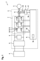
図1は、インバータ2の例示的な実施形態と、部分的または完全に電動式であり得るビークルを駆動するように構成された電気機械3とを備えた、アセンブリ1の例示的な実施形態のブロック図である。アセンブリ1は、本例では高電圧バッテリとして設計されるDC電圧源4をさらに備える。
Figure 1 is a block diagram of an exemplary embodiment of an
インバータ2は、本例ではEMCフィルタとして設計されるフィルタ装置5と、DCリンクコンデンサ6と、パワーユニット7と、制御装置8の例示的な実施形態と、第1の測定装置9と、第2の測定装置10と、アナログ・デジタル変換装置11とを備える。
The
パワーユニット7は、半導体スイッチング素子、例えば、IGBTやパワーMOSFETとして設計された複数のスイッチング素子12を備える。スイッチング素子12は、対で接続されてハーフブリッジを形成する。駆動回路14は、それぞれのスイッチング素子12の制御入力13の前に接続される。明確にするために、ここでは1つのスイッチング素子12および1つの駆動回路14のみに符号が付されている。駆動回路14は、電気機械3に給電するための電圧がハーフブリッジのそれぞれのタップで供与されるように提供される、制御装置8からのパルス幅変調スイッチング信号15を受け取る。したがって、パワーユニット7は、スイッチング信号15に応じて、DCリンクコンデンサ6によって平滑化されたDCリンク電圧を、この場合は3相を有する電圧に変換する。
The power unit 7 comprises a number of switching
第1の測定装置9は、相電流を取得し、第1の測定装置9のアナログ測定信号をデジタル電流情報16に変換するアナログ・デジタル変換装置11に測定信号を提供するように構成される。したがって、第2の測定装置10は、電気機械3の回転速度を取得し、第2の測定装置10のアナログ測定信号をデジタル回転速度情報17に変換するアナログ・デジタル変換装置11に測定信号を提供するように構成される。制御装置8は、その入力で電流情報16および回転速度情報17を受け取る。
The first measuring device 9 is configured to acquire the phase currents and provide a measurement signal to an analog-to-
制御装置8は、電流情報16および回転速度情報17に基づいて、電気機械3の回転速度およびトルクによって定義される動作点を記述する動作点情報を決定する。制御装置8は、パルス幅変調スイッチング信号15の搬送周波数を決定するように構成される。このために、制御装置8は、回転速度値とトルク値の対に搬送周波数値を割り当てる特性マップが格納されるメモリユニット18を備える。制御装置8は、動作点情報に基づいて、特性マップから対応する搬送周波数値を選択する。
Based on the
図2は、図1に示されるアセンブリを動作させるときの動作領域が描かれたトルク回転速度図であり、トルクはMで示され、回転速度はfrotで示されている。この例示的な実施形態では、スイッチング信号15は、連続空間ベクトル変調(SVM)によって決定されている。
Figure 2 is a torque rotational speed diagram illustrating the operating region when operating the assembly shown in Figure 1, where the torque is indicated by M and the rotational speed is indicated by frot . In this exemplary embodiment, the switching
この図は、各対と搬送周波数値との間の関連付けを記述する特性マップを示している。図2には、基本回転速度動作領域20から電力制限動作領域21内または弱め界磁動作領域内に移行するときの最大トルクの大きさを記述する、コーナ動作点19が最初に示されている。搬送周波数値の選択された等値線は、一点鎖線で示されている。
The figure shows a characteristic map describing the association between each pair and the carrier frequency value. In FIG. 2, a
第1の動作領域22は、下限回転速度23がゼロとは異なり、上限回転速度24が電力制限動作領域21または弱め界磁動作領域にある回転速度間隔内に広がる。第1の動作領域22の第1の境界25は、その回転速度が下限回転速度23に対応する基本回転速度動作領域にある第1の動作点26から、その回転速度が下限回転速度23よりも大きく、そのトルクの大きさが第1の動作点26のトルクの大きさよりも大きい第2の動作点27まで延びる。第2の動作点27は、電力制限動作領域21または弱め界磁動作領域にあり、第2の動作点27の回転速度におけるトルクの最大振幅から離間している。
The
第1の動作領域22の第2の境界28は、その回転速度が上限回転速度に対応する第1の動作点29から、第1の境界25の第2の動作点27と同一の第2の動作点まで延びる。
The
制御装置8は、回転速度の上昇およびトルクの大きさの減少に伴って、第1の動作領域22内の搬送周波数を増加させるように構成される。これは、この図以降では、矢印によって表されている。
The controller 8 is configured to increase the carrier frequency in the
第1の動作領域22と重ならないように定義された第2の動作領域30は、それぞれの回転速度におけるそのトルクの大きさが、第1の動作領域にあるこの回転速度におけるトルクの最大の大きさよりも大きい動作点を含む。第2の動作領域30は、完全に電力制限動作領域21または弱め界磁動作領域内に位置し、それぞれの回転速度に対してトルクの可能な最大の大きさが存在する特性マップに線で記述された全負荷動作30aまで及ぶ。制御装置8は、トルクとは無関係に、回転速度の上昇に伴って第2の動作領域30内で搬送周波数を増加させるように構成される。
The
制御装置8は、最終的に、事前定義された最小値を下回る搬送周波数を決定しないように構成される。この点に関して、最小値が指定されたさらなる動作領域31が描かれている。さらなる動作領域31は、第1の境界25の低回転速度側の動作点、および第2の動作領域30の境界28aを含む。
The control device 8 is ultimately configured not to determine a carrier frequency below a predefined minimum value. In this respect, a
要約すると、動作領域22、30、31の特性マップは、以下の関係を形成する。
式中、
fPWM(M,frot)は、トルクMおよび回転速度frotに依存して決定されるべき搬送周波数を記述し、
WTHDは、インバータ2の出力電圧の全高調波歪みの例示的な歪み尺度としての重み付き全高調波歪みを記述し、
fPWM,minは、最小搬送周波数を記述し、
fPWM,losses(M,frot)は、最小搬送周波数
fPWM,WTHD(M,frot)は、最小搬送周波数
f PWM (M, f rot ) describes the carrier frequency to be determined depending on the torque M and the rotation speed f rot ,
WTHD describes weighted total harmonic distortion as an exemplary distortion measure of the total harmonic distortion of the output voltage of
f PWM,min describes the minimum carrier frequency;
f PWM,losses (M,f rot ) is the minimum carrier frequency
f PWM,WTHD (M,f rot ) is the minimum carrier frequency
制御装置8は、搬送周波数を定期的に更新するように構成される。これは、例えば、更新された動作点情報の受け取り時、事前定義された、もしくは事前定義可能な期間が経過した後、電気機械3の電気周期の完結後、またはそれぞれのスイッチング信号15の期間の完了後に行われる。上記の更新イベントの組み合わせも可能である。
The control device 8 is configured to periodically update the carrier frequency. This occurs, for example, upon receipt of updated operating point information, after a predefined or predefinable period has elapsed, after completion of an electrical cycle of the electric machine 3 or after completion of the period of the
図3および図4は、SVMが使用される先行技術による図1に対応するアセンブリに関する。しかしながら、このアセンブリでは、搬送周波数がトルク回転速度図のすべての動作点に対して一定の10kHzに指定されるものとする。 Figures 3 and 4 relate to an assembly corresponding to Figure 1 according to the prior art, in which an SVM is used. However, in this assembly, the carrier frequency is specified as a constant 10 kHz for all operating points of the torque-speed diagram.
図3は、先行技術によるアセンブリのWTHDが描かれたトルク回転速度図である。WTHDは、図3に、WTHDの値がパーセント単位で与えられる等値線で示されている。WTHDは、基本的に回転速度の増加と共に上昇し、大きさが低いトルクで特に顕著であることが分かる。ここで、高い値のWTHDは、電気機械3に不必要な振動を引き起こす可能性がある。 Figure 3 is a torque-speed diagram plotting the WTHD of an assembly according to the prior art. The WTHD is shown in Figure 3 as a contour line where the value of the WTHD is given in percentage. It can be seen that the WTHD essentially rises with increasing rotational speed and the magnitude is particularly noticeable at low torques. Here, high values of WTHD can cause unwanted vibrations in the electric machine 3.
図4は、先行技術によるアセンブリのインバータの全損失が描かれたトルク回転速度図である。全損失は、図4に、全損失の値がkW単位で与えられる等値線で示されている。大雑把には、10kHzの一定の搬送周波数での全損失は、トルクの大きさが増加するに従って増加し、回転速度とはほとんど無関係である。 Figure 4 is a torque-speed diagram plotting the total losses of the inverter of a prior art assembly. The total losses are shown in Figure 4 as contour lines giving the value of the total losses in kW. Roughly speaking, at a constant carrier frequency of 10 kHz, the total losses increase with increasing torque magnitude and are almost independent of the rotational speed.
図5、図6および図7は、上述の図1および図2の例示的な実施形態に対応するアセンブリ1のさらなる例示的な実施形態に関する。アセンブリ1の具体的な設計は、ここでは、最大12000min-1の回転速度まで及び、約-250~250Nmのトルクをカバーする特性マップで示されている。搬送周波数の決定は動作点に依存する。スイッチング信号15は、SVMによって決定される。
Figures 5, 6 and 7 relate to further exemplary embodiments of the
図5は、さらなる例示的な実施形態の動作中の搬送周波数値が描かれたトルク回転速度図である。特性マップは、ここでは実験的に基づいて、またはシミュレーションによって決定されている。動作領域22、30、31、およびコーナ動作点19が示されている。
Figure 5 shows a torque-speed diagram with carrier frequency values during operation of a further exemplary embodiment. The characteristic map has been determined here on an experimental basis or by simulation. The operating
図6は、WTHDが描かれたトルク回転速度図であり、図は図3に対応する。図6と図3との比較より、動作点に依存して搬送周波数を決定することによって、1.3%の最大WTHD値が達成され、これは、先行技術による一定の搬送周波数仕様での3.0%を超える最大WTHD値よりも著しく低いことが分かる。 Figure 6 is a torque-speed diagram with WTHD plotted, which corresponds to Figure 3. Comparing Figure 6 with Figure 3, it can be seen that by determining the carrier frequency depending on the operating point, a maximum WTHD value of 1.3% is achieved, which is significantly lower than the maximum WTHD value of over 3.0% with a constant carrier frequency specification according to the prior art.
図7は、インバータ2の全損失が描かれたトルク回転速度図であり、図は図4に対応する。図7と図4との比較より、一定の搬送周波数仕様で高いWTHD値が発生する領域における全損失は、先行技術の前損失をわずかに上回って増加することが分かる。しかしながら、最大全損失は、スイッチング素子12の熱耐久性が特にこれに向けられなければならないため、特に注目に値する。これらは実質的に不変であることが有利である。よって、動作点に依存した搬送周波数仕様は、電気機械3の広い動作領域にわたって全高調波歪みを大幅に低減させることを可能にし、それによって最大全損失を増加させることはない。
Figure 7 is a torque-speed diagram in which the total losses of the
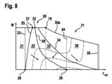
図8は、図1に示されたアセンブリ1のさらなる例示的な実施形態の動作に関する動作領域が描かれたトルク回転速度図である。この例示的な実施形態では、スイッチング信号15は、一般化された不連続パルス幅変調(GDPWM)によって、すなわち不連続変調方式を使用して決定される。
Figure 8 is a torque-speed diagram depicting the operating region for the operation of a further exemplary embodiment of the
図8には、回転速度の上昇およびトルクの大きさの減少に伴って搬送周波数がその範囲内で増加し、下限回転速度23と、電力制限動作領域21または弱め界磁動作領域にある上限回転速度24との間に広がる第1の動作領域22が再度示されている。第1の動作領域22の第1の境界25は、その回転速度が下限回転速度23に対応する基本回転速度動作領域20にある第1の動作点26から、その回転速度が下限回転速度23よりも大きく、そのトルクの大きさが第1の動作点26のトルクの大きさよりも大きい第2の動作点27まで延びる。しかしながら、第2の動作点27もまた基本回転速度動作領域20にあり、第1の境界27は全負荷動作領域30a内まで延びる。
8 again shows a
第1の動作領域22の第2の境界28は、その回転速度が上限回転速度24に対応する第1の動作点29から、ただし、基本回転速度動作領域20および全負荷動作領域30a内にあり、第1の境界25の第2の動作点27よりも高い回転速度を有する第2の動作点32まで延びる。
The
図8は、それぞれの回転速度におけるそのトルクの大きさが、第1の動作領域22にあるこの回転速度におけるトルクの最大の大きさよりも大きい動作点を含む、第1の動作領域22と重ならないように定義された特性マップの第2の動作領域33をさらに示している。第2の動作領域33は、第1の動作領域22に直接隣接している。第2の動作領域33の一方の境界34は、電力制限動作領域21または弱め界磁動作領域にある上限回転速度35から、最大、基本回転速度動作領域20内の全負荷動作領域30aまで延びる。制御装置8は、回転速度の低下およびトルクの減少に伴って第2の動作領域33内で搬送周波数を増加させるように構成される。
8 further shows a
特性マップでは第3の動作領域36も定義され、それぞれの回転速度におけるそのトルクの大きさが、動作領域22、33にあるこの回転速度におけるトルクの最大の大きさよりも大きい動作点を含む。第3の動作領域36は、第2の動作領域33の境界34を越えて、基本回転速度動作領域20と、電力制限動作領域21または弱め界磁動作領域とにある。制御装置8は、回転速度の上昇およびトルクの減少に伴って、または代替として、トルクとは無関係に、回転速度の上昇に伴って第3の動作領域36内で搬送周波数を増加させるように構成される。
A
他の点では、この例示的な実施形態は、図1および図2を参照して説明されたように、第1の例示的な実施形態に対応する。 In other respects, this exemplary embodiment corresponds to the first exemplary embodiment as described with reference to Figures 1 and 2.
図9および図10は、先行技術による図1に対応するアセンブリに関する。しかしながら、このアセンブリでは、搬送周波数がトルク回転速度図のすべての動作点に対して一定の15.9kHzに指定され、GDPWMが使用されるものとする。 Figures 9 and 10 relate to an assembly corresponding to Figure 1 according to the prior art. However, in this assembly, the carrier frequency is specified as a constant 15.9 kHz for all operating points of the torque-speed diagram, and GDPWM is used.
図9は、先行技術によるアセンブリのWTHDが描かれたトルク回転速度図である。WTHDは、図9に、WTHDの値がパーセント単位で与えられる等値線で示されている。異なるタイプの変調に起因して、WTHDは、図3によるSVMが使用される場合とは異なって分布することが分かる。近似として、ここでは、WTHDは小さな値のトルクに対してより高い値を用いると規定することができる。しかしながら、WTHDの全域的最大値は、電力制限動作領域または弱め界磁動作領域において0Nmのトルクで存在する。 Figure 9 is a torque-speed diagram plotted with the WTHD of an assembly according to the prior art. The WTHD is shown in Figure 9 as a contour line where the value of the WTHD is given in percentage. It can be seen that due to the different type of modulation, the WTHD is distributed differently than when the SVM according to Figure 3 is used. As an approximation, it can be defined here that the WTHD takes on higher values for small values of torque. However, the global maximum of the WTHD is present at a torque of 0 Nm in the power-limited or field-weakening operating region.
図10は、先行技術によるアセンブリのインバータの全損失が描かれたトルク回転速度図である。全損失は、図10に、全損失の値がkW単位で与えられる等値線で示されている。全損失の分布は、図4によるSVMによる分布にほぼ対応する。 Figure 10 shows a torque-speed diagram plotting the total losses of the inverter of an assembly according to the prior art. The total losses are shown in Figure 10 as contour lines giving the value of the total losses in kW. The distribution of the total losses corresponds approximately to the distribution according to the SVM according to Figure 4.
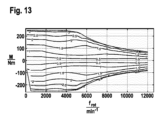
図11、図12および図13は、上述の図1および図8の例示的な実施形態に対応するアセンブリ1のさらなる例示的な実施形態に関する。アセンブリ1の具体的な設計は、ここでもやはり、最大12000min-1の回転速度まで及び、約-250~250Nmのトルクをカバーする特性マップで示されている。搬送周波数の決定は動作点に依存する。スイッチング信号15は、GDPWMによって決定される。
Figures 11, 12 and 13 relate to further exemplary embodiments of the
図11は、さらなる例示的な実施形態の動作中の搬送周波数値が描かれたトルク回転速度図である。特性マップは、ここでは実験的に基づいて、またはシミュレーションによって決定されている。動作領域22、31、33、36、およびコーナ動作点19が示されている。
Figure 11 is a torque-rotational speed diagram in which the carrier frequency values during operation of a further exemplary embodiment are plotted. The characteristic maps are determined here on an experimental basis or by simulation. The operating
図12は、WTHDが描かれたトルク回転速度図であり、図は図9に対応する。図12と図9との比較より、動作点に依存して搬送周波数を決定することによって、0.9%の最大WTHD値が達成され、これは、先行技術による一定の搬送周波数仕様での2.5%を超える最大WTHD値よりも著しく低いことが分かる。 Figure 12 is a torque-speed diagram with WTHD plotted, which corresponds to Figure 9. Comparing Figure 12 with Figure 9, it can be seen that by determining the carrier frequency depending on the operating point, a maximum WTHD value of 0.9% is achieved, which is significantly lower than the maximum WTHD value of over 2.5% with a constant carrier frequency specification according to the prior art.
図13は、インバータ2の全損失が描かれたトルク回転速度図であり、図は図10に対応する。図13と図10との比較より、図4および図7を参照して説明された利点は、GDPWMの使用によっても達成されることが分かる。
Figure 13 is a torque-speed diagram with the total losses of
以下のさらなる例示的な実施形態は、前述の例示的な実施形態のいずれかに基づくものとすることができ、制御装置8のさらなる例示的な実施形態によれば、特性マップは個別の対によって定義され、制御装置8は、個別の対に割り当てられた搬送周波数値の補間、特に線形補間によって搬送周波数を決定するように構成される。さらなる例示的な実施形態によれば、制御装置8は、特性マップに基づく代わりに動作点に依存して搬送周波数を決定することができる解析的計算仕様によって搬送周波数を決定するように構成される。さらなる例示的な実施形態によれば、トルク情報は、電流情報16を参照して得られるのではなく、スイッチング信号15を決定するための制御の状況において制御装置8によって推定または測定される。
The following further exemplary embodiments may be based on any of the preceding exemplary embodiments, according to further exemplary embodiments of the control device 8, the characteristic map is defined by individual pairs and the control device 8 is configured to determine the carrier frequency by interpolation, in particular linear interpolation, of the carrier frequency values assigned to the individual pairs. According to further exemplary embodiments, the control device 8 is configured to determine the carrier frequency by analytical calculation specifications, which allow the carrier frequency to be determined in dependence on the operating point instead of based on the characteristic map. According to further exemplary embodiments, the torque information is not obtained with reference to the
Claims (16)
前記電気機械(3)の回転速度およびトルクによって定義される動作点を記述する動作点情報に依存して前記搬送周波数を決定し、
前記回転速度が増加し、かつ、前記トルクの大きさが減少するに従い、下限回転速度(23)がゼロとは異なり、上限回転速度(24)が電力制限動作領域(21)または弱め界磁動作領域にある回転速度間隔内に広がる第1の動作領域(22)内で前記搬送周波数を増加させるように構成され、
それぞれの回転速度における前記トルクの前記大きさが、この回転速度における前記第1の動作領域(22)での前記トルクの最大の大きさよりも大きい動作点を含む、前記第1の動作領域(22)と重ならずに定義された第2の動作領域(30)内で、特に前記トルクとは無関係に、回転速度の上昇に伴って前記搬送周波数を増加させるように構成された、
ことを特徴とする、制御装置。 A control device (8) for an inverter (2) supplying an electric machine (3), configured to provide a pulse width modulated switching signal (15) having a carrier frequency for driving switching elements (12) of the inverter (2), comprising:
determining said carrier frequency in dependence on operating point information describing an operating point defined by a rotational speed and a torque of said electric machine (3);
as the rotational speed increases and the magnitude of the torque decreases, the carrier frequency is increased within a first operating region (22) having a lower limit rotational speed (23) different from zero and an upper limit rotational speed (24) extending within a rotational speed interval that is in a power limited operating region (21) or a field weakening operating region ;
configured to increase the carrier frequency with increasing rotational speed, in particular independently of the torque, within a second operating region (30) defined without overlapping with the first operating region (22) and including operating points where the magnitude of the torque at each rotational speed is greater than the maximum magnitude of the torque in the first operating region (22) at this rotational speed.
A control device comprising:
前記第1の動作領域の第2の境界(28)が、前記回転速度が前記上限回転速度(24)に対応する第1の動作点(29)から、前記回転速度が前記上限回転速度(29)よりも低く、前記トルクの前記大きさが前記第1の動作点(29)の前記トルクの前記大きさよりも大きい第2の動作点(27)まで延びる、
請求項1に記載の制御装置。 a first boundary (25) of the first operating range (22) extends from a first operating point (26) at which the rotational speed corresponds to the lower limit rotational speed (23) to a second operating point (27) at which the rotational speed is greater than the lower limit rotational speed (23) and at which the magnitude of the torque is greater than the magnitude of the torque of the first operating point (26); and/or
a second boundary (28) of the first operating region extends from a first operating point (29) where the rotational speed corresponds to the upper rotational speed (24) to a second operating point (27) where the rotational speed is lower than the upper rotational speed (29) and where the magnitude of the torque is greater than the magnitude of the torque of the first operating point (29);
The control device according to claim 1 .
同一であり、かつ/または、
前記電力制限動作領域(21)もしくは前記弱め界磁動作領域にあり、かつ/または、
それぞれの前記第2の動作点(27)の前記回転速度における前記トルクの最大の大きさから離間している、
請求項2に記載の制御装置。 The second operating point (27) of the first boundary (25) and the second boundary (28) is
are identical and/or
in the power-limited operating region (21) or the field-weakening operating region; and/or
each said second operating point (27) being spaced apart from a maximum magnitude of said torque at said rotational speed;
The control device according to claim 2.
請求項1から3のいずれか一項に記載の制御装置。 the second operating region (30) extends entirely within the power limited operating region (21) or the field weakening operating region and/or up to maximum full load operation (30a);
A control device according to any one of claims 1 to 3 .
請求項1から4のいずれか一項に記載の制御装置。 configured to generate said pulse width modulated switching signal (15) by continuous pulse width modulation, in particular by space vector modulation,
A control device according to any one of claims 1 to 4 .
請求項1または2に記載の制御装置。 and configured to increase the carrier frequency with decreasing rotation speed and decreasing torque within a second operating region (33) defined without overlapping with the first operating region (22) and including an operating point in which the magnitude of the torque at each rotation speed is greater than a maximum magnitude of the torque in the first operating region (22) at the rotation speed.
The control device according to claim 1 or 2.
請求項1、2または6のいずれか一項に記載の制御装置。 configured to increase the carrier frequency with increasing rotational speed with increasing rotational speed and decreasing torque or independently of torque within a third operating region (36) defined without overlapping with the first operating region (22) and including an operating point where the magnitude of the torque at each rotational speed is greater than a maximum magnitude of the torque in the first operating region (22) at that rotational speed.
7. A control device according to claim 1, 2 or 6 .
請求項7に記載の制御装置。 the third operating region (36) includes operating points at which the magnitude of the torque at each rotational speed is greater than a maximum magnitude of the torque at this rotational speed in the second operating region (33),
The control device according to claim 7 .
全負荷動作領域(30a)内まで及び、かつ/または、
基本回転速度動作領域(20)から前記電力制限動作領域(21)もしくは前記弱め界磁動作領域内まで及ぶ、
請求項1または2に記載の制御装置。 The first operating area (22) and/or the second operating area ( 30)
and/or within the full load operating region (30a);
ranging from a base rotation speed operating region (20) to within the power limited operating region (21) or the field weakening operating region;
The control device according to claim 1 or 2 .
全負荷動作領域(30a)内まで及び、かつ/または、
基本回転速度動作領域(20)から前記電力制限動作領域(21)もしくは前記弱め界磁動作領域内まで及ぶ、
請求項7または8のいずれか一項に記載の制御装置。 The first motion area (22) and/or the second motion area (33) and/or the third motion area (36)
and/or within the full load operating region (30a);
ranging from a base rotation speed operating region (20) to within the power limited operating region (21) or the field weakening operating region;
A control device according to any one of claims 7 and 8 .
請求項1もしくは2に記載の、または請求項7から10のいずれか一項に記載の制御装置。 configured to generate said pulse width modulated switching signal (15) by discontinuous pulse width modulation, in particular by generalized discontinuous pulse width modulation,
A control device according to claim 1 or 2 or according to any one of claims 7 to 10.
請求項1から11のいずれか一項に記載の制御装置(8)と、
を備えた、インバータ(2)。 a switching element (12) configured to convert a voltage present on the input side into an alternating current for operating an electric machine (3) in response to a switching signal controlling said switching element (12);
A control device (8) according to any one of claims 1 to 11,
An inverter (2).


fPWM(M,frot)が、トルクMおよび回転速度frotに依存して決定されるべき前記搬送周波数を記述し、
mTHDが、前記インバータ(2)の出力電圧の全高調波歪みの歪み尺度を記述し、
fPWM,minが、事前定義された、または事前定義可能な最小搬送周波数を記述し、
fPWM,losses(M,frot)が、最小搬送周波数
請求項13に記載のアセンブリ。 wherein the determination of the carrier frequency represents the following relationship:
f PWM (M, f rot ) describes the carrier frequency to be determined in dependence on the torque M and the rotation speed f rot ,
m THD describes a distortion measure of the total harmonic distortion of the output voltage of the inverter (2);
f PWM,min describes a predefined or predefinable minimum carrier frequency;
f PWM,losses (M,f rot ) is the minimum carrier frequency
14. The assembly of claim 13.
前記インバータ(2)の動作のためのパルス幅変調スイッチング信号(15)の搬送周波数を、回転速度が増加し、トルクの大きさが減少するに従い、下限回転速度(23)がゼロとは異なり、上限回転速度(24)が電力制限動作領域(21)または弱め界磁動作領域にある回転速度間隔内に広がる第1の動作領域(22)内で前記搬送周波数が増加するように、前記電気機械(3)の前記回転速度および前記トルクによって定義される動作点を記述する動作点情報に依存して決定するステップであって、それぞれの回転速度における前記トルクの前記大きさが、この回転速度における前記第1の動作領域(22)での前記トルクの最大の大きさよりも大きい動作点を含む、前記第1の動作領域(22)と重ならずに定義された第2の動作領域(30)内で、特に前記トルクとは無関係に、回転速度の上昇に伴って前記搬送周波数を増加させるステップと、
前記インバータ(2)のスイッチング素子(12)に前記パルス幅変調スイッチング信号(15)を供給するステップと、
を含む、方法。 A method for operating an inverter (2) for powering an electric machine (3), carried out by a controller (8), comprising the steps of:
determining a carrier frequency of a pulse width modulated switching signal (15) for the operation of the inverter (2) in dependence on operating point information describing operating points defined by the rotational speed and the torque of the electric machine (3) such that the carrier frequency increases as the rotational speed increases and the magnitude of the torque decreases in a first operating region (22) extending within a rotational speed interval whose lower limit rotational speed (23) is different from zero and whose upper limit rotational speed (24) is in a power limited operating region (21) or in a field weakening operating region, wherein the carrier frequency increases with increasing rotational speed, in particular independently of the torque, in a second operating region (30) defined without overlapping with the first operating region (22) including operating points whose magnitude of the torque at the respective rotational speed is greater than the maximum magnitude of the torque in the first operating region (22) at this rotational speed;
supplying said pulse width modulated switching signal (15) to a switching element (12) of said inverter (2);
A method comprising:
Applications Claiming Priority (3)
| Application Number | Priority Date | Filing Date | Title |
|---|---|---|---|
| DE102019120439.9A DE102019120439A1 (en) | 2019-07-29 | 2019-07-29 | Control device, inverter, arrangement with an inverter and an electrical machine, method for operating an inverter and computer program |
| DE102019120439.9 | 2019-07-29 | ||
| PCT/EP2020/071117 WO2021018829A1 (en) | 2019-07-29 | 2020-07-27 | Control device, inverter, assembly having an inverter and an electric machine, method for operating an inverter and computer program |
Publications (2)
| Publication Number | Publication Date |
|---|---|
| JP2022542983A JP2022542983A (en) | 2022-10-07 |
| JP7635200B2 true JP7635200B2 (en) | 2025-02-25 |
Family
ID=71786978
Family Applications (1)
| Application Number | Title | Priority Date | Filing Date |
|---|---|---|---|
| JP2022506203A Active JP7635200B2 (en) | 2019-07-29 | 2020-07-27 | Control device, inverter, assembly with inverter and electric machine, method for operating inverter and computer program - Patents.com |
Country Status (8)
| Country | Link |
|---|---|
| US (1) | US12027998B2 (en) |
| EP (1) | EP4005086B1 (en) |
| JP (1) | JP7635200B2 (en) |
| KR (1) | KR102911567B1 (en) |
| CN (1) | CN113939995A (en) |
| DE (1) | DE102019120439A1 (en) |
| HU (1) | HUE070056T2 (en) |
| WO (1) | WO2021018829A1 (en) |
Families Citing this family (2)
| Publication number | Priority date | Publication date | Assignee | Title |
|---|---|---|---|---|
| CN113071330B (en) * | 2021-04-16 | 2022-12-02 | 中国第一汽车股份有限公司 | Motor torque control method, system, vehicle and storage medium |
| CN114444335B (en) * | 2022-04-08 | 2022-06-21 | 北京精雕科技集团有限公司 | Motor flux weakening multiple optimization method and system, electronic equipment and storage medium |
Citations (5)
| Publication number | Priority date | Publication date | Assignee | Title |
|---|---|---|---|---|
| JP2002010668A (en) | 2000-06-28 | 2002-01-11 | Nissan Motor Co Ltd | Motor control device for electric vehicles |
| JP2007267527A (en) | 2006-03-29 | 2007-10-11 | Toyota Motor Corp | Control device for electric vehicle |
| JP2008022671A (en) | 2006-07-14 | 2008-01-31 | Toyota Motor Corp | Inverter control device, inverter control method, and vehicle |
| JP2017184535A (en) | 2016-03-31 | 2017-10-05 | アイシン・エィ・ダブリュ株式会社 | Inverter controller |
| JP2018019515A (en) | 2016-07-28 | 2018-02-01 | 三菱自動車工業株式会社 | Inverter control device |
Family Cites Families (16)
| Publication number | Priority date | Publication date | Assignee | Title |
|---|---|---|---|---|
| JP4839780B2 (en) * | 2004-12-28 | 2011-12-21 | トヨタ自動車株式会社 | Motor control device and vehicle |
| US8165737B2 (en) | 2007-10-24 | 2012-04-24 | GM Global Technology Operations LLC | Method and system for controlling a power inverter in electric drives of vehicles with two-mode transmissions |
| JP4978429B2 (en) * | 2007-11-01 | 2012-07-18 | アイシン・エィ・ダブリュ株式会社 | Electric motor control device, electric vehicle and hybrid electric vehicle |
| JP4605274B2 (en) | 2008-08-27 | 2011-01-05 | トヨタ自動車株式会社 | vehicle |
| JP4730420B2 (en) * | 2008-10-09 | 2011-07-20 | トヨタ自動車株式会社 | Motor drive device and control method of motor drive device |
| JP2010221856A (en) * | 2009-03-24 | 2010-10-07 | Hitachi Automotive Systems Ltd | Steering control device |
| JP5035641B2 (en) * | 2009-11-30 | 2012-09-26 | アイシン・エィ・ダブリュ株式会社 | Control device for motor drive device |
| WO2014157629A1 (en) * | 2013-03-29 | 2014-10-02 | アイシン・エィ・ダブリュ株式会社 | Drive device for rotary electric machine |
| JP6184753B2 (en) * | 2013-05-30 | 2017-08-23 | コベルコ建機株式会社 | Inverter device for motor drive |
| US9595907B2 (en) | 2014-03-28 | 2017-03-14 | Deere & Company | System and method for controlling modulation of an inverter |
| JP5994812B2 (en) | 2014-04-28 | 2016-09-21 | トヨタ自動車株式会社 | vehicle |
| DE102014225099A1 (en) * | 2014-12-08 | 2016-06-09 | Zf Friedrichshafen Ag | Circuit and method for driving an inverter in a three-phase machine |
| US10027262B2 (en) * | 2016-09-13 | 2018-07-17 | Ford Global Technologies, Llc | Pseudorandom PWM variation based on motor operating point |
| DE102017203668A1 (en) | 2017-03-07 | 2018-09-13 | Robert Bosch Gmbh | Method and device for operating an inverter for a drive system |
| US10320323B1 (en) * | 2018-03-28 | 2019-06-11 | Infineon Technologies Austria Ag | Pulse width modulation (PWM) scheme for single shunt motor control |
| US20200186077A1 (en) * | 2018-12-11 | 2020-06-11 | Hamilton Sundstrand Corporation | Electrical system for vehicles having overvoltage protection |
-
2019
- 2019-07-29 DE DE102019120439.9A patent/DE102019120439A1/en active Pending
-
2020
- 2020-07-27 KR KR1020227003386A patent/KR102911567B1/en active Active
- 2020-07-27 CN CN202080042277.4A patent/CN113939995A/en active Pending
- 2020-07-27 HU HUE20746210A patent/HUE070056T2/en unknown
- 2020-07-27 JP JP2022506203A patent/JP7635200B2/en active Active
- 2020-07-27 WO PCT/EP2020/071117 patent/WO2021018829A1/en not_active Ceased
- 2020-07-27 US US17/630,279 patent/US12027998B2/en active Active
- 2020-07-27 EP EP20746210.2A patent/EP4005086B1/en active Active
Patent Citations (5)
| Publication number | Priority date | Publication date | Assignee | Title |
|---|---|---|---|---|
| JP2002010668A (en) | 2000-06-28 | 2002-01-11 | Nissan Motor Co Ltd | Motor control device for electric vehicles |
| JP2007267527A (en) | 2006-03-29 | 2007-10-11 | Toyota Motor Corp | Control device for electric vehicle |
| JP2008022671A (en) | 2006-07-14 | 2008-01-31 | Toyota Motor Corp | Inverter control device, inverter control method, and vehicle |
| JP2017184535A (en) | 2016-03-31 | 2017-10-05 | アイシン・エィ・ダブリュ株式会社 | Inverter controller |
| JP2018019515A (en) | 2016-07-28 | 2018-02-01 | 三菱自動車工業株式会社 | Inverter control device |
Also Published As
| Publication number | Publication date |
|---|---|
| EP4005086B1 (en) | 2024-11-20 |
| DE102019120439A1 (en) | 2021-02-04 |
| CN113939995A (en) | 2022-01-14 |
| US20220337175A1 (en) | 2022-10-20 |
| JP2022542983A (en) | 2022-10-07 |
| HUE070056T2 (en) | 2025-05-28 |
| KR20220041098A (en) | 2022-03-31 |
| WO2021018829A1 (en) | 2021-02-04 |
| US12027998B2 (en) | 2024-07-02 |
| KR102911567B1 (en) | 2026-01-12 |
| EP4005086A1 (en) | 2022-06-01 |
Similar Documents
| Publication | Publication Date | Title |
|---|---|---|
| RU2391767C2 (en) | Device and method for control of drive system from electric motor | |
| CN101826811B (en) | Voltage source inverter with a voltage offset | |
| CN101953065B (en) | Motor drive control device | |
| CN101647192B (en) | Motor drive control device and drive control method | |
| CN104885358B (en) | Inverter unit | |
| CN101174794A (en) | Power supply circuit and control circuit used therein | |
| JP2014176253A (en) | Power converter | |
| JP7635200B2 (en) | Control device, inverter, assembly with inverter and electric machine, method for operating inverter and computer program - Patents.com | |
| KR102848444B1 (en) | Control device, inverter, assembly comprising inverter and electric machine, method for operating inverter and computer program | |
| JP3848903B2 (en) | Power converter | |
| EP2618480A2 (en) | Motor control device and air conditioner | |
| JP2002204596A (en) | Inverter controlled generator | |
| JP7657029B2 (en) | Control device, inverter, apparatus with inverter and electric machine, method for operating an inverter, and computer program | |
| JP2005295776A (en) | PWM inverter control method | |
| JP2020014326A (en) | Electric power conversion device | |
| CN117713578A (en) | Inverter drive device and control method thereof | |
| JP5838554B2 (en) | Power converter | |
| JP2010220306A (en) | Motor control equipment | |
| US12074550B2 (en) | Control device, inverter, assembly having an inverter and an electrical machine, method for operating an inverter, and computer program | |
| CN106458045A (en) | Electric vehicle control device | |
| JP4248560B2 (en) | Power converter | |
| JP3152295B2 (en) | Inverter control method and device | |
| JP2004166460A (en) | Motor drive | |
| JP3333852B2 (en) | Inverter for air conditioner | |
| JPH1132496A (en) | Motor control device |
Legal Events
| Date | Code | Title | Description |
|---|---|---|---|
| A621 | Written request for application examination |
Free format text: JAPANESE INTERMEDIATE CODE: A621 Effective date: 20230724 |
|
| A131 | Notification of reasons for refusal |
Free format text: JAPANESE INTERMEDIATE CODE: A131 Effective date: 20240723 |
|
| A521 | Request for written amendment filed |
Free format text: JAPANESE INTERMEDIATE CODE: A523 Effective date: 20241023 |
|
| TRDD | Decision of grant or rejection written | ||
| A01 | Written decision to grant a patent or to grant a registration (utility model) |
Free format text: JAPANESE INTERMEDIATE CODE: A01 Effective date: 20250121 |
|
| A61 | First payment of annual fees (during grant procedure) |
Free format text: JAPANESE INTERMEDIATE CODE: A61 Effective date: 20250212 |
|
| R150 | Certificate of patent or registration of utility model |
Ref document number: 7635200 Country of ref document: JP Free format text: JAPANESE INTERMEDIATE CODE: R150 |