JP7635166B2 - Control system and control device for press molding machine, and slide stop control method - Google Patents
Control system and control device for press molding machine, and slide stop control method Download PDFInfo
- Publication number
- JP7635166B2 JP7635166B2 JP2022001706A JP2022001706A JP7635166B2 JP 7635166 B2 JP7635166 B2 JP 7635166B2 JP 2022001706 A JP2022001706 A JP 2022001706A JP 2022001706 A JP2022001706 A JP 2022001706A JP 7635166 B2 JP7635166 B2 JP 7635166B2
- Authority
- JP
- Japan
- Prior art keywords
- timing
- slide
- workpiece
- flywheel
- press
- Prior art date
- Legal status (The legal status is an assumption and is not a legal conclusion. Google has not performed a legal analysis and makes no representation as to the accuracy of the status listed.)
- Active
Links
- 238000000465 moulding Methods 0.000 title claims description 73
- 238000000034 method Methods 0.000 title claims description 44
- 238000012545 processing Methods 0.000 claims description 37
- 230000009467 reduction Effects 0.000 claims description 16
- 230000007246 mechanism Effects 0.000 claims description 14
- 238000006243 chemical reaction Methods 0.000 claims description 13
- 238000001514 detection method Methods 0.000 claims description 8
- 230000004913 activation Effects 0.000 claims description 2
- 230000008569 process Effects 0.000 description 33
- 239000000047 product Substances 0.000 description 16
- 238000005242 forging Methods 0.000 description 11
- 230000008859 change Effects 0.000 description 6
- 238000004364 calculation method Methods 0.000 description 4
- 238000012937 correction Methods 0.000 description 4
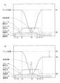
- 238000010586 diagram Methods 0.000 description 4
- 230000007423 decrease Effects 0.000 description 3
- 238000006073 displacement reaction Methods 0.000 description 3
- 238000005259 measurement Methods 0.000 description 3
- 230000001174 ascending effect Effects 0.000 description 2
- 230000006870 function Effects 0.000 description 2
- 239000000463 material Substances 0.000 description 2
- 230000004048 modification Effects 0.000 description 2
- 238000012986 modification Methods 0.000 description 2
- 230000004044 response Effects 0.000 description 2
- 238000012360 testing method Methods 0.000 description 2
- 230000032258 transport Effects 0.000 description 2
- 238000011144 upstream manufacturing Methods 0.000 description 2
- 229910000831 Steel Inorganic materials 0.000 description 1
- 230000009471 action Effects 0.000 description 1
- 230000000694 effects Effects 0.000 description 1
- 239000012467 final product Substances 0.000 description 1
- 230000010365 information processing Effects 0.000 description 1
- 238000010801 machine learning Methods 0.000 description 1
- 238000003754 machining Methods 0.000 description 1
- 230000004043 responsiveness Effects 0.000 description 1
- 230000000630 rising effect Effects 0.000 description 1
- 238000009751 slip forming Methods 0.000 description 1
- 239000010959 steel Substances 0.000 description 1
- 230000007704 transition Effects 0.000 description 1
Images


Landscapes
- Control Of Presses (AREA)
Description
本発明は、プレス成形機の制御システムおよび制御装置、ならびにスライド停止制御方法に関する。 The present invention relates to a control system and control device for a press molding machine, and a slide stop control method.
従来より、クランク軸を回転駆動し、上型を取り付けたスライドを昇降させる機械式の鍛造プレス成形機が知られている。このようなプレス成形機では、クランク軸の一端が、クラッチを介してフライホイールに連結されており、クラッチの入り/切り(ON/OFF)、および、ブレーキ装置の入り/切り(ON/OFF)を繰り返すことにより、クランク軸の下方に連結されたスライドが上下運動する。このようなスライドの上下運動に伴って、下降工程、加圧工程、および上昇工程を1サイクルとしたプレスサイクルが繰り返し実行されるので、上流側から順次搬送されてくるワークを連続的に成形する(量産する)ことができる。 Mechanical forging press machines have been known in the past that rotate a crankshaft to raise and lower a slide with an upper die attached. In such press machines, one end of the crankshaft is connected to a flywheel via a clutch, and the slide connected below the crankshaft moves up and down by repeatedly turning the clutch on and off (ON/OFF) and the brake device on and off (ON/OFF). As the slide moves up and down, a press cycle consisting of a lowering process, a pressurizing process, and a rising process is repeatedly executed, so that workpieces transported in sequence from the upstream side can be continuously formed (mass-produced).
ワークを連続的に成形するプレス成形機においてワークの加工精度を高めるためには、プレスサイクルごとに(上昇工程の終了時に)スライドを上死点で停止させる必要がある。ワークをスライドにより押圧加工する際、ワークに与える成形力の大きさに応じてフライホイールの速度が減少するため、たとえば特公昭47-28262号公報(特許文献1)では、フライホイール駆動側回転部の速度変化に対応させてブレーキ操作時期を選択させるための機構を設けた上死点停止位置制御装置が提案されている。 In order to improve the machining accuracy of a workpiece in a press molding machine that continuously molds the workpiece, it is necessary to stop the slide at the top dead center for each press cycle (at the end of the ascending process). When the workpiece is pressed by the slide, the speed of the flywheel decreases depending on the magnitude of the molding force applied to the workpiece. For example, Japanese Patent Publication No. 47-28262 (Patent Document 1) proposes a top dead center stop position control device that has a mechanism for selecting the timing of brake operation in response to the speed change of the rotating part on the flywheel drive side.
特許文献1に示されるように、従来は、プレスサイクル中に、加圧工程によるフライホイールやスライドの速度変化を検知することにより、ブレーキ入りタイミングの補正が行われていた。
As shown in
しかしながら、このように加圧工程による実際の速度変化を検知して補正後のブレーキ入りタイミングを算出する場合、タイミングが間に合わず、上死点でスライドを停止させることができないケースがあった。 However, when detecting the actual speed change due to the pressurizing process and calculating the corrected brake application timing in this way, there were cases where the timing was not enough to stop the slide at the top dead center.
本発明は、上記のような課題を解決するためになされたものであって、その目的は、精度良く、スライドを上死点で停止させることのできるプレス成形機の制御システムおよび制御装置、ならびにスライド停止制御方法を提供することである。 The present invention has been made to solve the above problems, and its purpose is to provide a control system and control device for a press molding machine, as well as a slide stopping control method, that can stop the slide at the top dead center with high accuracy.
この発明のある局面に従うプレス成形機の制御システムは、フライホイールと、フライホイールの回転運動を上下運動に変換する変換機構と、変換機構に連結されたスライドと、変換機構に作用してスライドの上下運動を停止させるブレーキ装置とを備えたプレス成形機において、前記スライドを上死点で停止させるための制御システムであって、決定処理手段と、記憶手段と、停止制御手段とを備える。決定処理手段は、品番ごとに、加圧成形後のフライホイールの速度減少を事前に測定することにより、スライドを上死点で停止させるためのブレーキ入りタイミングを決定する。記憶手段は、決定処理手段により品番ごとに決定されたブレーキ入りタイミングに関するタイミング情報を記憶する。停止制御手段は、プレスサイクル期間中に、記憶手段に記憶されたタイミング情報に基づいて、プレス対象の品番に対応するブレーキ入りタイミングでブレーキ装置を作動することにより、スライドを停止させる。 A control system for a press molding machine according to one aspect of the present invention is a control system for stopping the slide at the top dead center in a press molding machine having a flywheel, a conversion mechanism that converts the rotational motion of the flywheel into vertical motion, a slide connected to the conversion mechanism, and a brake device that acts on the conversion mechanism to stop the vertical motion of the slide, and includes a determination processing means, a storage means, and a stop control means. The determination processing means determines the brake application timing for stopping the slide at the top dead center by measuring in advance the speed reduction of the flywheel after pressure molding for each part number. The storage means stores timing information related to the brake application timing determined for each part number by the determination processing means. The stop control means stops the slide during the press cycle by operating the brake device at the brake application timing corresponding to the part number of the object to be pressed, based on the timing information stored in the storage means.
好ましくは、決定処理手段は、任意のタイミングでブレーキ装置の作動を行った場合のスライドの停止高さのずれ量をさらに測定して、品番ごとのブレーキ入りタイミングを決定する。 Preferably, the determination processing means further measures the deviation in the stopping height of the slide when the brake device is activated at any timing, and determines the brake activation timing for each part number.
好ましくは、決定処理手段は、ブレーキ入りタイミングとともにクラッチ切りタイミングを決定する。 Preferably, the determination processing means determines the clutch disengagement timing as well as the brake engagement timing.
プレス成形機は、1つまたは複数の金型でワークを成形する成形機であり、当該制御システムは、金型へのワークの配置パターンを検出する検出手段をさらに備えている。この場合、決定処理手段は、品番とワークの配置パターンとの組み合わせごとに、ブレーキ入りタイミングを決定し、停止制御手段は、検出手段により検出されたワークの配置パターンに応じたブレーキ入りタイミングで、ブレーキ装置を作動することが望ましい。 The press molding machine is a molding machine that molds a workpiece using one or more dies, and the control system further includes a detection means for detecting the arrangement pattern of the workpiece on the dies. In this case, it is preferable that the determination processing means determines the brake application timing for each combination of the product number and the workpiece arrangement pattern, and the stop control means activates the brake device at the brake application timing according to the workpiece arrangement pattern detected by the detection means.
好ましくは、記憶手段のタイミング情報は、品番およびワークの配置パターンを識別する識別情報とフライホイールの速度とを対応付けた速度対応情報と、フライホイールの速度とブレーキ入りタイミングとの相関関係を示す相関情報とを含む。 Preferably, the timing information in the storage means includes speed correspondence information that associates identification information that identifies the part number and the workpiece arrangement pattern with the flywheel speed, and correlation information that indicates the correlation between the flywheel speed and the brake application timing.
この発明の他の局面に従うプレス成形機の制御装置は、上記構成のプレス成形機において、前記スライドを上死点で停止させるための制御装置あって、記憶手段と、停止制御手段とを備える。記憶手段は、品番ごとに、加圧成形後のフライホイールの速度減少を事前に測定することにより算出された、スライドを上死点で停止させるためのブレーキ入りタイミングに関するタイミング情報を記憶する。停止制御手段は、プレスサイクル期間中に、記憶手段に記憶されたタイミング情報に基づいて、プレス対象の品番に対応するブレーキ入りタイミングでブレーキ装置を作動することにより、スライドを停止させる。 A control device for a press molding machine according to another aspect of the present invention is a control device for stopping the slide at the top dead center in a press molding machine having the above configuration, and includes a storage means and a stop control means. The storage means stores timing information regarding the timing of braking to stop the slide at the top dead center, which is calculated for each part number by measuring in advance the speed reduction of the flywheel after pressure molding. The stop control means stops the slide during the press cycle by operating the brake device at the braking timing corresponding to the part number of the object to be pressed, based on the timing information stored in the storage means.
この発明の他の局面に従うスライド停止制御方法は、上記構成のプレス成形機において、スライドを上死点で停止させるための方法であって、品番ごとに、加圧成形後のフライホイールの速度減少を事前に測定することにより、スライドを上死点で停止させるためのブレーキ入りタイミングを決定するステップと、品番ごとに決定されたブレーキ入りタイミングに関するタイミング情報を記憶手段に記憶するステップと、プレスサイクル期間中に、記憶手段に記憶されたタイミング情報に基づいて、プレス対象の品番に対応するブレーキ入りタイミングでブレーキ装置を作動することにより、スライドを停止させるステップとを備える。 A slide stop control method according to another aspect of the present invention is a method for stopping a slide at the top dead center in a press molding machine having the above configuration, and includes the steps of: determining the brake application timing for stopping the slide at the top dead center by measuring in advance the speed reduction of the flywheel after pressure molding for each part number; storing timing information regarding the brake application timing determined for each part number in a storage means; and stopping the slide during the press cycle by operating the brake device at the brake application timing corresponding to the part number of the object to be pressed based on the timing information stored in the storage means.
本発明によれば、精度良く、スライドを上死点で停止させることができる。 According to the present invention, the slide can be stopped at the top dead center with high precision.
本発明の実施の形態について図面を参照しながら詳細に説明する。なお、図中同一または相当部分には同一符号を付してその説明は繰返さない。 The embodiment of the present invention will be described in detail with reference to the drawings. Note that the same or corresponding parts in the drawings are given the same reference numerals and their description will not be repeated.
<鍛造プレス装置の概略構成>
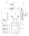
はじめに、図1を参照して、鍛造プレス装置10の概略構成について説明する。鍛造プレス装置10は、ワークをプレス加工するプレス成形機11と、プレス成形機11を制御する制御装置40とを備えている。制御装置40は、典型的にはPLC(プログラマブル・ロジック・コントローラ)により実現される。
<Outline of the forging press device>
First, a schematic configuration of a forging
プレス成形機11は、フレーム3内の上下に対向するように設けられたスライド1およびボルスタ2を備えている。プレス成形機11は、クランク軸4を回転駆動させることにより、コンロッド5に連結されたスライド1が昇降動作するように構成されている。クランク軸4およびコンロッド5は、フライホイール8の回転運動を上下運動に変換する変換機構の一例である。
The
クランク軸4の一端側には、モータ6でベルト7によって回転駆動されるフライホイール8が、クラッチ9を介して接続されている。モータ6はたとえばサーボモータである。クランク軸4の他端側には、ブレーキ装置12が取り付けられている。ブレーキ装置12は、クランク軸4の回転を止めることにより、スライド1の上下運動を停止させる。
A
プレス成形機11は、モータ6でフライホイール8を一定速度で回転駆動し、クラッチ9を入りとして、フライホイール8の回転をクランク軸4に伝達することによってスライド1を昇降させて、ボルスタ2上に載置されたワークを鍛造する。ワークは、ボルスタ2上に設置された下型(図示せず)とスライド1の下端に設置された上型(図示せず)とを含む金型に応じた大きさおよび形状に加工され、最終製品となる。「金型」とは、鍛造に使用される型を意味する。金型は、典型的には特殊鋼により形成される。
In the
鍛造プレス装置10は、図示しない搬送装置(たとえばベルトコンベア)によって前工程から搬送されたワークをプレス成形機11(ボルスタ2の位置)まで搬送し、プレス成形機11で連続的にワークの加圧成形を行う。つまり、制御装置40が、クラッチ9の入り/切りおよびブレーキ装置12の入り/切りを繰り返してスライド1を昇降制御することにより、プレス成形機11が、上流側から順次搬送されてくるワークを連続的に成形する(量産する)。
The forging
鍛造プレス装置10は、荷重センサ20、角度センサ21,24、ダイハイト変位センサ22、およびワークセンサ23を含む複数のセンサ類を備えている。荷重センサ20は、たとえば、フレーム3の歪みを検出する歪みゲージで構成され、ワークに加わる荷重を検知する。角度センサ21は、クランク軸4の回転角度(プレス角度)を検出する。これにより、スライド1の位置、および、スライド1の速度(ストローク)を計測することができる。角度センサ24は、フライホイール8の回転角度を検出する。これにより、フライホイール8の速度を計測することができる。ダイハイト変位センサ22は、プレス成形機11のダイハイト(ボルスタ2とスライド1の下死点位置との間隔)を検出する。ワークセンサ23は、搬送装置上のワークの有無、すなわちプレス成形機11へのワークの搬送有無を検知する(図2参照)。これにより、後述するように、金型へのワークの配置パターンを検出することができる。
The forging
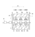
本実施の形態におけるプレス成形機11は、複数の金型で段階的にワークを成形する多段式のプレス成形機であってもよい。この場合の金型の配置例を図2に示す。図2の例では、プレス成形機11が、ワークWの搬送方向A1に沿って配置された3個の金型51~53を備えている。この場合、ワークWは、金型51による第1工程(工程I)、金型52による第2工程(工程II)、金型53による第3工程(工程III)を順に経て、段階的に成形される。
The
金型51~53それぞれの上型51a,52a,53aは、フレーム3内のスライド1の下端部に固定されており、同時に昇降移動する。金型51~53それぞれの下型51b,52b,53bは、フレーム3内のボルスタ2の上端部に固定されている。この場合、金型51~53にワークがあるパターン、金型51~53のいずれか1つまたは2つにワークがあるパターンなど、複数種類のワークの配置パターンでプレス成形可能である。なお、以下の説明において、上下三対の型51a,51b,52a,52b,53a,53bを区別する必要がない場合には、これらを「金型50」と表現する。金型50は、ワークの品番によって変更されることがある。
The
「品番」とは、“生産される品物”に対するプレスのプログラム番号を表わす。典型的には、金型50の形状(種類)および材料の種類ごとに、品番が定められている。なお、一つの品番に複数種類の材料が割り当てられていてもよい。 "Product number" refers to the press program number for the "product to be produced." Typically, a product number is determined for each shape (type) of die 50 and type of material. Note that multiple types of materials may be assigned to one product number.
図6(A)は、スライド1の1サイクル(プレスサイクル)におけるクラッチ9の入り/切りタイミングおよびブレーキ装置12の入り/切りタイミングを例示したタイミングチャートである。図6(A)では、スライド1の変位量を示すスライド波形に重畳させて、クラッチ9の制御に伴うクラッチ圧力、ブレーキ装置12の制御に伴うブレーキ緩圧力、ならびに成形荷重の波形を示している。成形荷重は、荷重センサ20により検出可能である。
Figure 6 (A) is a timing chart illustrating the on/off timing of the
1サイクルの開始時点において、スライド1は上死点高さHaに待機している。このとき、クラッチ9の状態は切り状態(OFF)であり、ブレーキ装置12の状態は入り状態(OFF)である。
At the start of one cycle, the
制御装置40は、はじめに、ブレーキ装置12にブレーキ緩信号を送信することによりブレーキ装置12の作動を解除し(時間t1)、引き続き、クラッチ9にクラッチON信号を送信することによりクラッチ9をONにする(時間t2)。これにより、クランク軸4がフライホイール8と供回りするので、待機状態から下降工程に移行する。すなわち、フライホイール8の回転に伴ってスライド1が下降し始める(時間t3)。スライド1が下死点高さHbまで下降することにより(時間t4)、加圧工程が実行される。加圧工程では、スライド1に固定された上型とボルスタ2に固定された下型とでワークの加圧成形が行われる。
The
制御装置40は、スライド1が下死点高さHbを通過した後の上昇工程において、クラッチ9をOFFにし(時間t5)、引き続き、ブレーキ装置12を作動させる(時間t6)。これにより、スライド1が、理想的には、元の上死点高さHaで停止する(時間t7)。
During the ascent process after the
フライホイール8を用いたプレス成形機11では、加工工程における成形エネルギー(成形荷重)の違いによりフライホイール8の速度減少度合が異なるため、ブレーキ開始時間、すなわちブレーキ入りタイミング(時間t6)を一定にすると、スライド1の停止位置にばらつきが生じる可能性がある。具体的には、図6(B)に示されるように、加圧工程において、図6(A)に示す成形荷重よりも高い成形荷重が生じた場合、フライホイール8の速度減少が比較的大きくなり、スライド1の速度が低下するため、スライド1は、上昇工程の終了時に上死点(待機位置)の手前で停止する。成形エネルギーは、ワークの品番によって異なることが多く、また、同じ品番でも、ワークの配置パターンによって異なることが多い。
In a
このような不具合を防止するために、下死点通過後のスライド1の速度を検知して、その検知結果に応じてブレーキ入りタイミング(時間t6)を補正することが考えられるが、応答性等の問題により、所望の結果が得られない可能性がある。つまり、プレスサイクル中に、加圧工程によるスライド1の実際の速度変化を検知して補正後のブレーキ入りタイミングを算出する場合、タイミングが間に合わず、上死点高さHaでスライド1を停止させることができないおそれがある。
To prevent such a problem, it is conceivable to detect the speed of
そこで、本実施の形態では、学習フェイズ(ブレーキ入りタイミングの決定フェイズ)において、品番ごとに、より望ましくは、品番とワークの配置パターンとの組み合わせ(以下「成形パターン」という)ごとに、加圧成形後のフライホイール8の速度減少を測定することにより、スライド1を上死点で停止させるためのブレーキ入りタイミングを決定する。これにより、プレス実行フェイズにおいては、ブレーキ入りタイミングの補正値の演算を行う必要がなくなるので、プレスサイクルごとに、最適なブレーキ入りタイミングでブレーキ装置12を作動し、スライド1を上死点で停止させることが可能となる。
In this embodiment, therefore, in the learning phase (phase for determining the brake application timing), the brake application timing for stopping the
図1に示されるように制御装置40とは別の学習装置70において、最適なブレーキ入りタイミングの決定処理(予測処理)を実行してもよいし、制御装置40が、最適なブレーキ入りタイミングの決定処理も行うようにしてもよい。つまり、プレス成形機11においてスライド1を上死点で停止させるための制御システム100は、制御装置40単体で構成されてもよいし、制御装置40と学習装置70とで構成されてもよい。学習装置70は、パーソナルコンピュータなどの情報処理装置により実現可能である。
As shown in FIG. 1, a
以下の説明では、制御装置40が、ブレーキ入りタイミングの決定処理(予測処理)も行うものと仮定する。
In the following explanation, it is assumed that the
<制御装置の機能構成>
図3(A)は、本発明の実施の形態における制御装置40の機能構成を示す機能ブロック図である。
<Functional configuration of the control device>
FIG. 3A is a functional block diagram showing the functional configuration of the
制御装置40は、CPU(Central Processing Unit)などにより実現されるプロセッサ41と、各種データおよびプログラムを記憶する記憶部42と、計時動作を行う計時部43と、ユーザからの指示を受け付ける操作部44と、上述のセンサ類からの信号を入力する入力部45と、プレス成形機11の各部に信号を出力する出力部46とを備えている。制御装置40は鍛造プレス装置10全体の制御を行うため、プロセッサ41は、基本の機能構成として、プレス実行フェイズにおいて作動するプレス制御部47を含んでいる。
The
本実施の形態に係るプレス成形機の制御システム100を構成する制御装置40は、決定処理部61、停止制御部62、およびタイミング情報記憶部63を有している。
The
決定処理部61は、品番ごと(より望ましくは成形パターンごと)に、加圧成形後のフライホイール8の速度減少を事前に測定することにより、スライド1を上死点で停止させるためのブレーキ入りタイミングを決定する処理を実行する。より具体的には、任意のタイミングでブレーキ装置12の作動を行った場合のスライド1の停止高さのずれ量をさらに測定して、その測定結果を用いて、品番ごと(より望ましくは成形パターンごと)の最適なブレーキ入りタイミングを算出により予測し、適宜調整を行って決定する。
The
プレス成形機11が多段式ではない場合のワークの配置パターンは、基本的には1種類となるが、ワークが適切に搬送されない場合などを考慮すると、金型にワークがあるパターンと金型にワークがない「ワークなしパターン」との2種類が考えられるため、プレス成形機11の金型が1つのみであっても、品番とワークの配置パターンとの組み合わせごと(つまり成形パターンごと)に、ブレーキ入りタイミングを決定することが望ましい。
When the
決定処理に用いる「任意のタイミング」は、デフォルトのタイミング、デフォルトのタイミングから所定時間分、前または後にずらしたタイミング、などを含み得る。本実施の形態では、デフォルトのタイミングが用いられるものとして説明する。 The "arbitrary timing" used in the determination process may include the default timing, a timing shifted a predetermined time from the default timing, either before or after the default timing, etc. In this embodiment, the description will be given assuming that the default timing is used.
決定処理部61はまた、ブレーキ入りタイミングとともに、クラッチ切りタイミングを決定することが望ましい。これにより、プレス実行フェイズにおけるスライド1の停止位置のばらつきを効果的に抑えることが可能となる。
The
タイミング情報記憶部63は、決定処理部61により決定されたブレーキ入りタイミングに関するタイミング情報を記憶する。具体的には、タイミング情報記憶部63に記憶されるタイミング情報は、成形パターンを識別する識別情報とフライホイール8の速度(減少後の速度)とを対応付けた速度対応情報と、フライホイール8の速度とブレーキ入りタイミングとの相関関係を示す相関情報とを含む。
The timing information storage unit 63 stores timing information regarding the brake application timing determined by the
速度対応情報63aの構造例を図3(B)に示す。図3(B)に示されるように、速度対応情報63aは、品番(No.1、2、・・・)、ワークの配置パターン(P1,P2,・・・)、および速度(Sa,Sb,・・・)の項目を含むデータテーブルの形式で、タイミング情報記憶部63に記録されている。これにより、品番およびワークの配置パターンとの組み合わせ、すなわち成形パターンと、測定されたフライホイール8の(速度減少後の)速度とが、1対1で対応付けられる。
An example of the structure of the
相関情報63bは、たとえば図3(C)のような折れ線グラフ等により表わすことができる。図3(C)では、横軸を速度とし、縦軸を所定の基準時間からの経過時間としたグラフ上に、測定されたフライホイール8の(速度減少後の)速度と、後述の決定処理により実際に算出(調整)したブレーキ入りタイミングとの交点同士を直線でつないでいる。ブレーキ入りタイミングの基準時間は、たとえば、ブレーキ切りタイミング(時間t1)であってもよいし、下死点に到達した時間(時間t4)であってもよいし、所定のプレス角度(たとえばスライド下降中の90°など)に達した時間であってもよい。
The
図3(C)のグラフには、ブレーキ入りタイミングの折れ線グラフとともにクラッチ切りタイミングの折れ線グラフが示されている。このように、相関情報63bは、フライホイール8の速度とクラッチ切りタイミングとの相関関係をさらに含んでもよい。なお、クラッチ切りタイミングは、(時間ベースではなく)プレス角度により制御されてもよい。また、ブレーキ入りタイミングの基準時間を、クラッチ切りタイミング(時間t5)としてもよく、その場合、ブレーキ入りタイミングのグラフは、略一定(横ばい)となることに留意されたい。
The graph in FIG. 3(C) shows a line graph of clutch disengagement timing along with a line graph of braking engagement timing. In this way, the
このように、タイミング情報が、速度対応情報63aと相関情報63bとに分けられることにより、各成形パターンについてのフライホイール8の速度さえ測定すれば、全ての成形パターンについてブレーキ入りタイミングを実際に算出(調整)しなくても、各成形パターンのブレーキ入りタイミングを相関情報63bにより特定することができる。
In this way, by dividing the timing information into
停止制御部62は、プレスサイクル期間中に、タイミング情報記憶部63に記憶されたタイミング情報に基づいて、プレス対象の品番に対応する(より望ましくは成形パターンに対応する)ブレーキ入りタイミングでブレーキ装置12を作動することにより、スライド1を停止させる制御を行う。これにより、停止制御部62は、スライド1の速度変化の大小に関わらず、スライド1を上死点で停止させることができる。
The
決定処理部61および停止制御部62の機能はそれぞれ、プロセッサ41がたとえば記憶部42に記憶されたプログラムを実行することにより実行される。停止制御部62は、プレス実行フェイズにおいて作動するため、プレス制御部47に含まれている。
The functions of the
タイミング情報記憶部63は、たとえば不揮発性の記憶装置により実現される。あるいは、クラウド上の記憶装置や、着脱可能な記憶媒体などによって実現されてもよい。 The timing information storage unit 63 is realized, for example, by a non-volatile storage device. Alternatively, it may be realized by a storage device on the cloud or a removable storage medium.
<ブレーキ入りタイミング決定フェイズ>
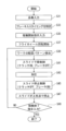
図4は、本実施の形態におけるブレーキ入りタイミングの決定方法を示すフローチャートである。図4に示す処理は、プロセッサ41の決定処理部61によって実行される。
<Brake application timing decision phase>
4 is a flowchart showing a method for determining the braking timing in this embodiment. The process shown in FIG.
図4を参照して、決定処理部61は、たとえば操作部44を介して、学習対象の品番の入力(指定)を受け付ける(ステップS1)。また、ワークの配置パターンの入力(指定)を受け付ける。あるいは、ワークセンサ23を利用して、ワークの配置パターンを検出してもよい。
Referring to FIG. 4, the
続いて、決定処理部61は、品番およびワークの配置パターンの組み合わせ、すなわち成形パターンに応じたプレス条件を特定する(ステップS3)。具体的には、フライホイール8の(初期の)回転速度と、たとえばデフォルトのクラッチ切りタイミングおよびブレーキ入りタイミングとを特定する。
Next, the
決定処理部61はモータ6を駆動し、特定した回転速度となるようにフライホイール8を回転させる。これにより、モータ6の回転エネルギーが、フライホイール8に蓄積される。フライホイール8は、一定の回転数で回転する。
The
続いて、決定処理部61は、ステップS1で指定した品番のワークを、同じくステップS1で指定した配置パターンで金型50に配置した状態で、スライド1の下降制御を行う(ステップS5)。具体的には、クラッチ9をONにするとともに、所定のブレーキ切りタイミングでブレーキ装置12をOFFにする。これにより、スライド1が下降し始める。決定処理部61は、たとえばこのタイミングでフライホイール8の回転速度の計測を開始する(ステップS7)。
Then, the
スライド1が下死点まで下降することにより、ワークの加圧が行われる(ステップS9)。これにより、成形エネルギーが発生し、フライホイール8の速度が減少する。
The
スライド1が下死点を通過してワークの加圧成形が終了すると、決定処理部61は、フライホイール8の速度計測を終了し、フライホイール8の(速度減少後の)速度を取得する(ステップS11)。
When the
決定処理部61は、続いて、スライド1の停止制御を行う(ステップS13)。具体的には、ステップS3で特定したクラッチ切りタイミングおよびブレーキ入りタイミングで、クラッチ9をOFFにするとともにブレーキ装置12をONにする。
The
このようなスライド1の停止制御により、スライド1が停止すると、スライド1の停止高さを計測する(ステップS15)。これにより、スライド1の停止高さと上死点高さとのずれの有無、および、ずれている場合のずれ量を判定(算出)することができる。このようなずれ量は、角度センサ21が検知したクランク軸4の回転角度から算出可能である。
When the
このようなフライホイール8の速度およびスライド1の停止高さの計測は、複数回行われることが望ましい。そのため、上記ステップS5~S15の処理をたとえば所定回実行する(ステップS17にてNO)。
It is desirable to measure the speed of the
ステップS3~S15の処理がたとえば複数回実行されると(ステップS17にてYES)、決定処理部61は、学習対象の成形パターンでのスライド停止タイミングを決定する(ステップS19)。具体的には、ステップS11で計測された、加圧成形後のフライホイール8の速度の統計値(たとえば平均値)を、その成形パターンの速度として算出する。そして、ステップS15で計測した複数回分のスライド1の停止高さの統計値(たとえば平均値)と上死点高さとのずれ量と、算出したフライホイール8の速度(平均速度)とに応じて、スライド1を上死点で停止させるためのブレーキ入りタイミングを算出する。決定処理部61は、今回の学習に用いた(ステップS3で特定した)ブレーキ入りタイミングからの補正値を算出することによって、スライド1を上死点で停止させるためのブレーキ入りタイミングを算出してもよい。
When the processes of steps S3 to S15 are executed multiple times (YES in step S17), the
このような計算は、たとえば、フライホイール8の元の速度、減少後の速度、およびスライド1の停止高さと上死点高さとのずれ量(クランク軸4の回転角度に相当)を変数とした所定の計算式によって実施することができる。なお、複数回分のスライド1の停止高さの統計値(たとえば平均値)と上死点高さとのずれ量が許容範囲内であれば、スライド1の停止高さのずれは無いと判断し、元のブレーキ入りタイミングを維持してもよい。
This calculation can be performed, for example, by a predetermined formula with the original speed of the
決定処理部61はまた、決定したブレーキ入りタイミングと今回の学習に用いた(ステップS3で特定した)クラッチ切りタイミングとの時間間隔が所定範囲に収まるように、適宜、クラッチ切りタイミングの補正値も算出することが望ましい。これにより、ブレーキ入りタイミングとクラッチ切りタイミングとの時間差の大小によるスライド1の停止位置の誤差を低減することができる。
It is also desirable for the
なお、ブレーキ入りタイミング(およびクラッチ切りタイミング)を実際に決定する際には、計算式を用いて得られたブレーキ入りタイミングを用いた場合にスライド1が上死点で停止するかどうかをテストし、テスト結果に応じてブレーキ入りタイミングを微調整することが望ましい。
When actually determining the braking timing (and clutch disengagement timing), it is advisable to test whether
決定処理部61は、ブレーキ入りタイミングおよびクラッチ切りタイミングを決定すると、今回の学習で決定したタイミング情報をタイミング情報記憶部63に記憶する(ステップS21)。具体的には、速度対応情報63aを構成するデータテーブルにおける対象の成形パターンの欄に、フライホイール8の速度を記憶するとともに、相関情報63bを構成するグラフ上に、決定したブレーキ入りタイミングおよびクラッチ切りタイミングをプロットする。
When the
決定処理部61は上述のようなタイミング決定処理を、全ての成形パターンについて実行してもよい。あるいは、加圧成形後のフライホイール8の速度だけを全ての成形パターンについて実行し、ブレーキ入りタイミングの算出(調整)は一部の成形パターンについてのみ実行してもよい。この場合、フライホイール8の速度が、たとえば5psmきざみなど略一定間隔となるように、調整対象の成形パターンを選択してもよい。これにより、決定処理を簡素化することができる。
The
なお、タイミング決定処理においては、インバータによりフライホイール8の速度を調整することにより、フライホイール8の速度減少を再現してもよい。
In addition, in the timing determination process, the speed reduction of the
<プレス実行フェイズ>
図5は、本実施の形態におけるプレス制御方法を示すフローチャートである。図5に示す処理は、プロセッサ41のプレス制御部47によって実行される。
<Press execution phase>
5 is a flowchart showing a press control method according to the present embodiment. The process shown in FIG.
図5を参照して、プレス制御部47は、はじめに、たとえば操作部44を介して、プレス対象の品番の入力(指定)を受け付ける(ステップS31)。これにより、タイミング情報記憶部63に記憶されたタイミング情報に基づいて、入力された品番に対応するワークの配置パターンごとのブレーキ入りタイミングおよびクラッチ切りタイミングを特定する(ステップS33)。
Referring to FIG. 5, the
具体的には、図3(B)および(C)に示した例を用いると、たとえば入力された品番が「1」であれば、まず、速度対応情報63aから品番「1」についてのワークの配置パターン(P1,P2・・・)ごとの速度(Sa,Sb,・・・)を抽出し、相関情報63bで規定される計算式により、抽出した各速度に対応するブレーキ入りタイミングおよびクラッチ切りタイミングを算出する。これにより、品番「1」のワークの配置パターン(P1,P2・・・)ごとのブレーキ入りタイミングおよびクラッチ切りタイミングが特定される。これらの情報は、たとえばプロセッサ41の内部メモリに一時記録される。
Specifically, using the example shown in Figures 3(B) and (C), if the input product number is "1", first, the speeds (Sa, Sb, ...) for each workpiece arrangement pattern (P1, P2, ...) for product number "1" are extracted from the
その後、プレス成形機11の稼働開始指示が入力されると(ステップS35)、プレス制御部47は、モータ6を駆動してフライホイール8の回転を開始する(ステップS37)。フライホイール8の回転速度は、入力された品番に対応する回転速度であり、事前学習での回転速度と同じである。
After that, when an instruction to start the operation of the
プレス制御部47は、入力部45を介して得られるワークセンサ23からの検知信号に基づいて、今回のプレスサイクルにおけるワークの配置パターンを検出する(ステップS39)。これにより、今回の成形パターン(品番とワークの配置パターンとの組み合わせ)が特定される。
The
続いて、プレス制御部47は、スライド1の下降制御を行う(ステップS41)。具体的には、クラッチ9をONにするとともに、所定のブレーキ切りタイミングでブレーキ装置12をOFFにする。これにより、スライド1が下降し始める。
The
スライド1が下死点まで下降することにより、ワークの加圧が行われる(ステップS43)。これにより、成形エネルギーが発生し、フライホイール8の速度が減少する。なお、品番やワークの配置パターンによっては、フライホイール8の速度が殆ど変わらない(減少しない)場合もある。
The
スライド1が下死点を通過してワークの加圧成形が終了すると、プレス制御部47の停止制御部62は、ステップS39で特定した今回の成形パターンに対応するブレーキ入りタイミングおよびクラッチ切りタイミングで、スライド1の停止制御を行う(ステップS45)。すなわち、ブレーキ装置12は、指定された品番に対応し、かつ、ワークセンサ23により検出されたワークの配置パターンに応じたブレーキ入りタイミングで作動する。クラッチ9も同様に、指定された品番に対応し、かつ、ワークセンサ23により検出されたワークの配置パターンに応じたクラッチ切りタイミングで、クランク軸4とフライホイール8との接続を遮断する。
When the
ブレーキ入りタイミングおよびクラッチ切りタイミングはプレス稼働開始時に(遅くともステップS43の加圧工程よりも前に)特定されているため、停止制御部62は、事前に決定した最適なタイミングで、クラッチ9をOFFにするとともにブレーキ装置12をONにすることができる。すなわち、図6(B)に示したようにフライホイール8の速度減少が比較的大きい場合であっても、最適なタイミングでクラッチ9をOFFにし(時間t5’)、適切なタイミングでブレーキ装置12を作動させる(時間t6’)ことができる。
The brake application timing and clutch release timing are specified when the press operation starts (at the latest before the pressurization step in step S43), so the
したがって、停止制御部62は、スライド1を上死点高さHaで停止させることができる(ステップS47)。つまり、次のプレスサイクルへの移行期に、スライド1を上死点高さHaで待機させることができるので、以降のプレスサイクルにおけるスライド位置のばらつきを低減できる。
The
このようにして今回のプレスサイクルが終わると、たとえば稼働終了指示が入力されるまで(ステップS49)、ステップS39~S47の処理が、プレスサイクルごとに繰り返し実行される。 When the current press cycle ends in this manner, the processes of steps S39 to S47 are repeatedly executed for each press cycle, for example, until an instruction to end operation is input (step S49).
<作用効果>
本実施の形態の制御システム100によると、プレスサイクル期間中(プレス実行フェイズ)にはフライホイール8の速度減少を考慮したタイミングの補正を行う必要がないので、応答性能等に関わらず、確実にスライド1を上死点で停止させることができる。
<Action and effect>
According to the
また、本実施の形態の制御システム100では、ワークの配置パターンに「ワークなしパターン」を含めているため、どのような状況であってもスライド1を確実性高く上死点で停止させることができる。
In addition, in the
その結果、プレス成形機11によって良品を量産することが可能となる。
As a result, it becomes possible to mass-produce quality products using the
<変形例>
本実施の形態では、ブレーキ入りタイミングの決定フェイズにおいて、決定処理部61が、デフォルトのブレーキ入りタイミングで複数回計測したスライド停止高さのずれ量を用いて、プレス実行フェイズで用いるブレーキ入りタイミングを算出することとしたが、このような例に限定されない。
<Modification>
In this embodiment, in the brake application timing determination phase, the
たとえば、1回目のサイクルにおいてスライド1の停止高さが上死点高さからずれていた場合(図4のステップS15)、次のサイクルでは、ブレーキ入りタイミングを所定時間前または後にずらして、スライド停止高さのずれ量を算出してもよい。また、このような処理が、スライド停止高さのずれ量が許容範囲となるまで繰り返し実行されてもよい。その際、ブレーキ入りタイミングとクラッチ切りタイミングとの時間間隔が所定範囲外となった場合に(時間間隔が短すぎるか長すぎる場合)、クラッチ切りタイミングを調整する処理が行われることが望ましい。
For example, if the stopping height of
あるいは、スライド入りタイミングの決定フェイズにおけるスライド制御制御では、従来のように加圧成形後のスライド1の速度変化からデフォルトのタイミングを演算により補正してもよい。この場合、図3(C)に示した相関情報63bを例示したグラフの縦軸は、デフォルトのブレーキ入りタイミングからの補正量を表わしていてもよい。
Alternatively, in the slide control in the slide engagement timing determination phase, the default timing may be corrected by calculation based on the speed change of the
また、決定処理部61による決定処理は、プレス実行フェイズから独立した学習フェイズにて行われることが望ましいものの、加圧成形後のフライホイール8の速度減少の測定および次以降のプレスサイクルでのブレーキ入りタイミングの決定(算出)を、プレス実行フェイズと並行して行ってもよい。この場合、決定処理部61および停止制御部62の両方がプレス制御部47に含まれてもよい。
Although it is preferable that the decision processing by the
また、本実施の形態では、タイミング情報記憶部63に記憶されるタイミング情報は、速度対応情報63aと相関情報63bとを含むこととしたが、このような例に限定されない。たとえば、成形パターンごとに、フライホイール8の速度、ブレーキ入りタイミング、およびクラッチ切りタイミングを対応付けて記録した一つの対応テーブルにより実現されてもよい。
In addition, in this embodiment, the timing information stored in the timing information storage unit 63 includes the
あるいは、タイミング情報記憶部63に記憶されるタイミング情報は、品番およびワークの配置パターン(成形パターン)を入力とし、ブレーキ入りタイミング(およびクラッチ切りタイミング)を出力とする学習済モデルにより実現されてもよい。この場合、決定処理部61は、成形パターンごとに、複数の教師データを用いた機械学習を実行すればよく、学習済モデルを生成することによって最適なブレーキ入りタイミングを決定できるようにしてもよい。
Alternatively, the timing information stored in the timing information storage unit 63 may be realized by a trained model that takes the part number and the workpiece arrangement pattern (molding pattern) as input and the brake application timing (and clutch disengagement timing) as output. In this case, the
今回開示された実施の形態はすべての点で例示であって制限的なものではないと考えられるべきである。本発明の範囲は上記した説明ではなくて特許請求の範囲によって示され、特許請求の範囲と均等の意味および範囲内でのすべての変更が含まれることが意図される。 The embodiments disclosed herein should be considered to be illustrative and not restrictive in all respects. The scope of the present invention is indicated by the claims, not by the above description, and is intended to include all modifications within the meaning and scope of the claims.
1 スライド、8 フライホイール、9, クラッチ、10 鍛造プレス装置、11 プレス成形機、12 ブレーキ装置、40 制御装置、50,51,52,53 金型、61 決定処理部、62 停止制御部、63 タイミング情報記憶部、63a 速度対応情報、63b 相関情報、70 学習装置、100 プレス成形機の制御システム。 1 slide, 8 flywheel, 9 clutch, 10 forging press device, 11 press molding machine, 12 brake device, 40 control device, 50, 51, 52, 53 die, 61 decision processing unit, 62 stop control unit, 63 timing information storage unit, 63a speed correspondence information, 63b correlation information, 70 learning device, 100 press molding machine control system.
Claims (6)
品番ごとに、加圧成形後の前記フライホイールの速度減少を事前に測定することにより、前記スライドを上死点で停止させるためのブレーキ入りタイミングを決定する決定処理手段と、
前記決定処理手段により品番ごとに決定された前記ブレーキ入りタイミングに関するタイミング情報を記憶する記憶手段と、
プレスサイクル期間中に、前記記憶手段に記憶された前記タイミング情報に基づいて、プレス対象の品番に対応する前記ブレーキ入りタイミングで前記ブレーキ装置を作動することにより、前記スライドを停止させる停止制御手段とを備え、
前記プレス成形機は、1つまたは複数の金型でワークを成形する成形機であり、
前記金型へのワークの配置パターンを検出する検出手段をさらに備え、
前記決定処理手段は、品番とワークの配置パターンとの組み合わせごとに、ブレーキ入りタイミングを決定し、
前記停止制御手段は、前記検出手段により検出されたワークの配置パターンに応じたブレーキ入りタイミングで、前記ブレーキ装置を作動する、プレス成形機の制御システム。 1. A control system for stopping the slide at a top dead center in a press molding machine including a flywheel, a conversion mechanism for converting a rotational motion of the flywheel into a vertical motion, a slide connected to the conversion mechanism, and a brake device acting on the conversion mechanism to stop the vertical motion of the slide, comprising:
a determination processing means for determining a brake application timing for stopping the slide at the top dead center by measuring in advance a speed reduction of the flywheel after pressure molding for each product number;
a storage means for storing timing information regarding the brake application timing determined for each product number by the determination processing means;
a stop control means for stopping the slide by operating the brake device at the brake application timing corresponding to the part number of the press object based on the timing information stored in the storage means during a press cycle period ,
The press molding machine is a molding machine that molds a workpiece using one or more dies,
Further, a detection means for detecting an arrangement pattern of the workpiece on the die is provided,
The determination processing means determines the brake application timing for each combination of the part number and the workpiece arrangement pattern,
A control system for a press molding machine , wherein the stop control means activates the brake device at a braking timing according to the workpiece arrangement pattern detected by the detection means .
品番とワークの配置パターンとの組み合わせごとに、加圧成形後の前記フライホイールの速度減少を事前に測定することにより算出された、前記スライドを上死点で停止させるためのブレーキ入りタイミングに関するタイミング情報を記憶する記憶手段と、
プレスサイクル期間中に、前記金型へのワークの配置パターンを検出する検出手段と、
プレスサイクル期間中に、前記記憶手段に記憶された前記タイミング情報に基づいて、プレス対象の品番および前記検出手段により検出されたワークの配置パターンに対応する前記ブレーキ入りタイミングで前記ブレーキ装置を作動することにより、前記スライドを停止させる停止制御手段とを備える、プレス成形機の制御装置。 A control device for stopping the slide at a top dead center in a press molding machine that includes a flywheel, a conversion mechanism that converts rotational motion of the flywheel into vertical motion, a slide connected to the conversion mechanism , and a brake device that acts on the conversion mechanism to stop the vertical motion of the slide, and that molds a workpiece with one or a plurality of dies , comprising:
a storage means for storing timing information regarding the timing of braking for stopping the slide at the top dead center, the timing information being calculated by measuring in advance the speed reduction of the flywheel after pressure molding for each combination of a part number and a workpiece arrangement pattern;
A detection means for detecting a layout pattern of a workpiece on the die during a press cycle;
and a stop control means for stopping the slide by operating the brake device at the brake application timing corresponding to the part number of the workpiece to be pressed and the arrangement pattern of the workpiece detected by the detection means , based on the timing information stored in the memory means, during a press cycle period.
品番とワークの配置パターンとの組み合わせごとに、加圧成形後の前記フライホイールの速度減少を事前に測定することにより、前記スライドを上死点で停止させるためのブレーキ入りタイミングを決定するステップと、
品番とワークの配置パターンとの組み合わせごとに決定された前記ブレーキ入りタイミングに関するタイミング情報を記憶手段に記憶するステップと、
プレスサイクル期間中に、前記金型へのワークの配置パターンを検出するステップと、
プレスサイクル期間中に、前記記憶手段に記憶された前記タイミング情報に基づいて、プレス対象の品番および検出されたワークの配置パターンに対応する前記ブレーキ入りタイミングで前記ブレーキ装置を作動することにより、前記スライドを停止させるステップとを備える、スライド停止制御方法。 A slide stop control method for stopping the slide at a top dead center in a press molding machine that includes a flywheel, a conversion mechanism that converts a rotational motion of the flywheel into vertical motion, a slide connected to the conversion mechanism , and a brake device that acts on the conversion mechanism to stop the vertical motion of the slide, and that molds a workpiece with one or a plurality of dies , comprising:
determining a brake application timing for stopping the slide at the top dead center by measuring in advance a speed reduction of the flywheel after pressure molding for each combination of part number and arrangement pattern of the workpiece ;
storing in a storage means timing information regarding the brake application timing determined for each combination of the part number and the arrangement pattern of the workpiece ;
Detecting a layout pattern of a workpiece on the die during a press cycle;
and stopping the slide by operating the brake device at the brake application timing corresponding to the part number of the press object and the detected arrangement pattern of the workpieces based on the timing information stored in the storage means during a press cycle period .
Priority Applications (1)
| Application Number | Priority Date | Filing Date | Title |
|---|---|---|---|
| JP2022001706A JP7635166B2 (en) | 2022-01-07 | 2022-01-07 | Control system and control device for press molding machine, and slide stop control method |
Applications Claiming Priority (1)
| Application Number | Priority Date | Filing Date | Title |
|---|---|---|---|
| JP2022001706A JP7635166B2 (en) | 2022-01-07 | 2022-01-07 | Control system and control device for press molding machine, and slide stop control method |
Publications (2)
| Publication Number | Publication Date |
|---|---|
| JP2023101219A JP2023101219A (en) | 2023-07-20 |
| JP7635166B2 true JP7635166B2 (en) | 2025-02-25 |
Family
ID=87201749
Family Applications (1)
| Application Number | Title | Priority Date | Filing Date |
|---|---|---|---|
| JP2022001706A Active JP7635166B2 (en) | 2022-01-07 | 2022-01-07 | Control system and control device for press molding machine, and slide stop control method |
Country Status (1)
| Country | Link |
|---|---|
| JP (1) | JP7635166B2 (en) |
Families Citing this family (1)
| Publication number | Priority date | Publication date | Assignee | Title |
|---|---|---|---|---|
| WO2026028335A1 (en) * | 2024-07-31 | 2026-02-05 | 三菱電機株式会社 | Motor control device and motor control method |
Citations (6)
| Publication number | Priority date | Publication date | Assignee | Title |
|---|---|---|---|---|
| JP2000263184A (en) | 1999-03-19 | 2000-09-26 | Sumitomo Heavy Ind Ltd | Controller for automatic apparatus in forging press line |
| US20020170444A1 (en) | 2000-02-29 | 2002-11-21 | David Schmitz | Method and apparatus for automatically positioning a press machine slide |
| JP2005144494A (en) | 2003-11-14 | 2005-06-09 | Fanuc Ltd | Numerical control mechanism and punch press machine |
| JP2006272462A (en) | 2003-05-01 | 2006-10-12 | Komatsu Ltd | Tandem press line, operation control method for tandem press line, and work transfer device for tandem press line |
| JP2008155228A (en) | 2006-12-21 | 2008-07-10 | Sumitomo Heavy Industries Techno-Fort Co Ltd | Method for controlling brake of press, and mechanical press |
| JP2009006385A (en) | 2007-06-29 | 2009-01-15 | Aida Eng Ltd | Method and device for controlling a plurality of press machines |
Family Cites Families (3)
| Publication number | Priority date | Publication date | Assignee | Title |
|---|---|---|---|---|
| JPS59120400A (en) * | 1982-12-28 | 1984-07-11 | Omron Tateisi Electronics Co | Progressive press |
| JPS62113838U (en) * | 1986-01-13 | 1987-07-20 | ||
| JPH0444320Y2 (en) * | 1987-03-25 | 1992-10-19 |
-
2022
- 2022-01-07 JP JP2022001706A patent/JP7635166B2/en active Active
Patent Citations (6)
| Publication number | Priority date | Publication date | Assignee | Title |
|---|---|---|---|---|
| JP2000263184A (en) | 1999-03-19 | 2000-09-26 | Sumitomo Heavy Ind Ltd | Controller for automatic apparatus in forging press line |
| US20020170444A1 (en) | 2000-02-29 | 2002-11-21 | David Schmitz | Method and apparatus for automatically positioning a press machine slide |
| JP2006272462A (en) | 2003-05-01 | 2006-10-12 | Komatsu Ltd | Tandem press line, operation control method for tandem press line, and work transfer device for tandem press line |
| JP2005144494A (en) | 2003-11-14 | 2005-06-09 | Fanuc Ltd | Numerical control mechanism and punch press machine |
| JP2008155228A (en) | 2006-12-21 | 2008-07-10 | Sumitomo Heavy Industries Techno-Fort Co Ltd | Method for controlling brake of press, and mechanical press |
| JP2009006385A (en) | 2007-06-29 | 2009-01-15 | Aida Eng Ltd | Method and device for controlling a plurality of press machines |
Also Published As
| Publication number | Publication date |
|---|---|
| JP2023101219A (en) | 2023-07-20 |
Similar Documents
| Publication | Publication Date | Title |
|---|---|---|
| EP0773075B1 (en) | Method and device for controlling, checking or optimizing pressure of cushion pin cylinders of press by discharging fluid or initial pressure | |
| US7757526B2 (en) | Method for changing force control gain and die cushion control apparatus | |
| JP7635166B2 (en) | Control system and control device for press molding machine, and slide stop control method | |
| CN104741431B (en) | Die buffer force control method and die cushion | |
| SE426372B (en) | SET AND DEVICE FOR MONITORING A PRESS | |
| JP2004520939A5 (en) | ||
| US5457980A (en) | Method and device for controlling, checking or optimizing pressure of cushion pin cylinders of press by discharging fluid or initial pressure | |
| JP2023062709A5 (en) | Processing system and method for manufacturing workpiece | |
| JP3537059B2 (en) | Press die height correction device | |
| JP7704548B2 (en) | Anomaly prediction device and program | |
| US7619384B2 (en) | Controller for die cushion mechanism | |
| WO2004091899A1 (en) | Press-forming machine | |
| JPS60191700A (en) | Liquid pressure press | |
| JP5649133B2 (en) | Press machine | |
| CN109482701A (en) | Fold generates detection device, die cushion, mold protecting device and its method | |
| WO2018173458A1 (en) | Motion generation device, press device, motion generation method, and motion generation program | |
| JP4799074B2 (en) | Powder compression molding machine and control method thereof | |
| JP3791995B2 (en) | Apparatus and method for controlling drawing process of direct acting press | |
| JP2000198000A (en) | Press molding apparatus and molding method | |
| JP6871132B2 (en) | Press equipment | |
| KR20160134901A (en) | A Servo die cushion apparatus have the control accuracy improvement function | |
| JP2021053691A (en) | Learning device and program, abnormality factor estimating system as well as forging press device | |
| JP2001162400A (en) | Screw press | |
| JP2722936B2 (en) | Automatic change device for wrinkle holding load of press machine | |
| JP6719781B2 (en) | Misfeed detection device |
Legal Events
| Date | Code | Title | Description |
|---|---|---|---|
| A621 | Written request for application examination |
Free format text: JAPANESE INTERMEDIATE CODE: A621 Effective date: 20231222 |
|
| A977 | Report on retrieval |
Free format text: JAPANESE INTERMEDIATE CODE: A971007 Effective date: 20240913 |
|
| A131 | Notification of reasons for refusal |
Free format text: JAPANESE INTERMEDIATE CODE: A131 Effective date: 20240917 |
|
| A521 | Request for written amendment filed |
Free format text: JAPANESE INTERMEDIATE CODE: A523 Effective date: 20241111 |
|
| A131 | Notification of reasons for refusal |
Free format text: JAPANESE INTERMEDIATE CODE: A131 Effective date: 20241203 |
|
| A521 | Request for written amendment filed |
Free format text: JAPANESE INTERMEDIATE CODE: A523 Effective date: 20250121 |
|
| TRDD | Decision of grant or rejection written | ||
| A01 | Written decision to grant a patent or to grant a registration (utility model) |
Free format text: JAPANESE INTERMEDIATE CODE: A01 Effective date: 20250204 |
|
| A61 | First payment of annual fees (during grant procedure) |
Free format text: JAPANESE INTERMEDIATE CODE: A61 Effective date: 20250212 |
|
| R150 | Certificate of patent or registration of utility model |
Ref document number: 7635166 Country of ref document: JP Free format text: JAPANESE INTERMEDIATE CODE: R150 |