JP7635162B2 - Ship-steering support device and ship-steering support method - Google Patents
Ship-steering support device and ship-steering support method Download PDFInfo
- Publication number
- JP7635162B2 JP7635162B2 JP2021573027A JP2021573027A JP7635162B2 JP 7635162 B2 JP7635162 B2 JP 7635162B2 JP 2021573027 A JP2021573027 A JP 2021573027A JP 2021573027 A JP2021573027 A JP 2021573027A JP 7635162 B2 JP7635162 B2 JP 7635162B2
- Authority
- JP
- Japan
- Prior art keywords
- ship
- zone
- collision
- speed
- future
- Prior art date
- Legal status (The legal status is an assumption and is not a legal conclusion. Google has not performed a legal analysis and makes no representation as to the accuracy of the status listed.)
- Active
Links
- 238000000034 method Methods 0.000 title claims description 10
- 238000000926 separation method Methods 0.000 claims description 56
- 230000006870 function Effects 0.000 description 18
- 238000010586 diagram Methods 0.000 description 11
- 230000007423 decrease Effects 0.000 description 4
- 239000003086 colorant Substances 0.000 description 3
- 230000000694 effects Effects 0.000 description 2
- 238000007796 conventional method Methods 0.000 description 1
- 238000005516 engineering process Methods 0.000 description 1
- 239000004973 liquid crystal related substance Substances 0.000 description 1
- 238000004904 shortening Methods 0.000 description 1
- 239000007787 solid Substances 0.000 description 1
- XLYOFNOQVPJJNP-UHFFFAOYSA-N water Substances O XLYOFNOQVPJJNP-UHFFFAOYSA-N 0.000 description 1
Images


Classifications
-
- G—PHYSICS
- G05—CONTROLLING; REGULATING
- G05D—SYSTEMS FOR CONTROLLING OR REGULATING NON-ELECTRIC VARIABLES
- G05D1/00—Control of position, course, altitude or attitude of land, water, air or space vehicles, e.g. using automatic pilots
- G05D1/02—Control of position or course in two dimensions
- G05D1/0206—Control of position or course in two dimensions specially adapted to water vehicles
-
- B—PERFORMING OPERATIONS; TRANSPORTING
- B63—SHIPS OR OTHER WATERBORNE VESSELS; RELATED EQUIPMENT
- B63B—SHIPS OR OTHER WATERBORNE VESSELS; EQUIPMENT FOR SHIPPING
- B63B43/00—Improving safety of vessels, e.g. damage control, not otherwise provided for
- B63B43/18—Improving safety of vessels, e.g. damage control, not otherwise provided for preventing collision or grounding; reducing collision damage
-
- B—PERFORMING OPERATIONS; TRANSPORTING
- B63—SHIPS OR OTHER WATERBORNE VESSELS; RELATED EQUIPMENT
- B63B—SHIPS OR OTHER WATERBORNE VESSELS; EQUIPMENT FOR SHIPPING
- B63B49/00—Arrangements of nautical instruments or navigational aids
-
- B—PERFORMING OPERATIONS; TRANSPORTING
- B63—SHIPS OR OTHER WATERBORNE VESSELS; RELATED EQUIPMENT
- B63B—SHIPS OR OTHER WATERBORNE VESSELS; EQUIPMENT FOR SHIPPING
- B63B79/00—Monitoring properties or operating parameters of vessels in operation
- B63B79/30—Monitoring properties or operating parameters of vessels in operation for diagnosing, testing or predicting the integrity or performance of vessels
-
- B—PERFORMING OPERATIONS; TRANSPORTING
- B63—SHIPS OR OTHER WATERBORNE VESSELS; RELATED EQUIPMENT
- B63B—SHIPS OR OTHER WATERBORNE VESSELS; EQUIPMENT FOR SHIPPING
- B63B79/00—Monitoring properties or operating parameters of vessels in operation
- B63B79/40—Monitoring properties or operating parameters of vessels in operation for controlling the operation of vessels, e.g. monitoring their speed, routing or maintenance schedules
-
- G—PHYSICS
- G01—MEASURING; TESTING
- G01C—MEASURING DISTANCES, LEVELS OR BEARINGS; SURVEYING; NAVIGATION; GYROSCOPIC INSTRUMENTS; PHOTOGRAMMETRY OR VIDEOGRAMMETRY
- G01C21/00—Navigation; Navigational instruments not provided for in groups G01C1/00 - G01C19/00
- G01C21/20—Instruments for performing navigational calculations
- G01C21/203—Instruments for performing navigational calculations specially adapted for water-borne vessels
-
- G—PHYSICS
- G01—MEASURING; TESTING
- G01S—RADIO DIRECTION-FINDING; RADIO NAVIGATION; DETERMINING DISTANCE OR VELOCITY BY USE OF RADIO WAVES; LOCATING OR PRESENCE-DETECTING BY USE OF THE REFLECTION OR RERADIATION OF RADIO WAVES; ANALOGOUS ARRANGEMENTS USING OTHER WAVES
- G01S13/00—Systems using the reflection or reradiation of radio waves, e.g. radar systems; Analogous systems using reflection or reradiation of waves whose nature or wavelength is irrelevant or unspecified
- G01S13/88—Radar or analogous systems specially adapted for specific applications
- G01S13/93—Radar or analogous systems specially adapted for specific applications for anti-collision purposes
- G01S13/937—Radar or analogous systems specially adapted for specific applications for anti-collision purposes of marine craft
-
- G—PHYSICS
- G08—SIGNALLING
- G08G—TRAFFIC CONTROL SYSTEMS
- G08G3/00—Traffic control systems for marine craft
- G08G3/02—Anti-collision systems
-
- G—PHYSICS
- G01—MEASURING; TESTING
- G01S—RADIO DIRECTION-FINDING; RADIO NAVIGATION; DETERMINING DISTANCE OR VELOCITY BY USE OF RADIO WAVES; LOCATING OR PRESENCE-DETECTING BY USE OF THE REFLECTION OR RERADIATION OF RADIO WAVES; ANALOGOUS ARRANGEMENTS USING OTHER WAVES
- G01S13/00—Systems using the reflection or reradiation of radio waves, e.g. radar systems; Analogous systems using reflection or reradiation of waves whose nature or wavelength is irrelevant or unspecified
- G01S13/66—Radar-tracking systems; Analogous systems
-
- G—PHYSICS
- G01—MEASURING; TESTING
- G01S—RADIO DIRECTION-FINDING; RADIO NAVIGATION; DETERMINING DISTANCE OR VELOCITY BY USE OF RADIO WAVES; LOCATING OR PRESENCE-DETECTING BY USE OF THE REFLECTION OR RERADIATION OF RADIO WAVES; ANALOGOUS ARRANGEMENTS USING OTHER WAVES
- G01S7/00—Details of systems according to groups G01S13/00, G01S15/00, G01S17/00
- G01S7/02—Details of systems according to groups G01S13/00, G01S15/00, G01S17/00 of systems according to group G01S13/00
- G01S7/04—Display arrangements
- G01S7/06—Cathode-ray tube displays or other two dimensional or three-dimensional displays
- G01S7/10—Providing two-dimensional and co-ordinated display of distance and direction
- G01S7/12—Plan-position indicators, i.e. P.P.I.
Landscapes
- Engineering & Computer Science (AREA)
- Radar, Positioning & Navigation (AREA)
- Remote Sensing (AREA)
- Ocean & Marine Engineering (AREA)
- Physics & Mathematics (AREA)
- Combustion & Propulsion (AREA)
- Mechanical Engineering (AREA)
- Chemical & Material Sciences (AREA)
- General Physics & Mathematics (AREA)
- Automation & Control Theory (AREA)
- Computer Networks & Wireless Communication (AREA)
- Public Health (AREA)
- Health & Medical Sciences (AREA)
- Electromagnetism (AREA)
- Aviation & Aerospace Engineering (AREA)
- Traffic Control Systems (AREA)
- Paper (AREA)
- Electrical Discharge Machining, Electrochemical Machining, And Combined Machining (AREA)
Description
本発明は、操船支援装置に関する。 The present invention relates to a ship steering assistance device.
従来から、自船及び他船の航行情報を利用して、自他船の衝突が将来的に発生するゾーンを計算することができる操船支援装置が知られている。非特許文献1は、この種の操船支援装置による当該ゾーンの計算手法を開示する。
Ship-steering support devices are known that can use navigation information of the ship and other ships to calculate a zone in which a collision between the ship and other ships will occur in the future. Non-Patent
非特許文献1は、自船行動空間の中で相手船の存在とその運動により妨げられる空間であるOZT(Obstacle Zоne by Target)を計算 する手法を開示する。非特許文献1によるOZTの計算手法は、以下のとおりである。即ち、自他船に発生する速力誤差を考慮して、任意のポイントに自他船が 到達する時間を確率的に示した到達時間確率分布を定義することにより、任意のポイントにおける自他船の同時存在確率を求める。この同時存在確率が所定の確 率値よりも高い場所を、衝突の可能性があるOZTとする。Non-Patent
しかし、上記非特許文献1の手法では、自船及び他船を点とみなしてOZTを計算しており、自船及び他船の実際の大きさを考慮していない。これにより、表示 上ではOZTを回避するように操船者が操船しても、自船及び他船が物理的な大きさを現実に有していることにより、船舶同士の異常接近又は衝突が生じるおそ れがある。However, in the method described in
また、非特許文献1のように自他船の同時存在確率を求めることによりOZTを得る手法は、計算量が極めて大き くなる。従って、非特許文献1の手法では、OZT計算点を増加させることが計算負荷の観点から難しく、OZTの表示の空間的分解能を向上させることが困難 になっていた。
In addition, the method of obtaining OZT by calculating the probability of simultaneous presence of one's own ship and another ship, as in Non-Patent
本発明は以上の事情に鑑みてされたものであり、その目的は、衝突の危険性を精度良く示す表示データを生成することができ、且つ、表示データ生成の計算負荷の軽減が図られた操船支援装置を提供することにある。The present invention has been made in consideration of the above circumstances, and its purpose is to provide a ship steering assistance device that is capable of generating display data that accurately indicates the risk of collision and that reduces the computational load of generating the display data.
本発明の解決しようとする課題は以上の如くであり、次にこの課題を解決するための手段とその効果を説明する。The problem that this invention aims to solve is as described above. Next, we will explain the means for solving this problem and its effects.
本発明の観点によれば、以下の構成の操船支援装置が提供される。即ち、この操船支援装置は、他船データ取得部と、他船将来位置予測部と、自船データ取得部 と、自船将来位置予測部と、リスク計算部と、表示データ生成部と、を備える。前記他船データ取得部は、他船の位置及び速度に関する情報を取得する。前記他 船将来位置予測部は、前記他船データ取得部が取得した他船の位置及び速度に基づいて、当該他船が同じ針路で、かつ同じ船速で航行を継続した場合に、将来の 複数の時刻における他船の位置を予測する。前記自船データ取得部は、自船の位置及び速度に関する情報を取得する。前記自船将来位置予測部は、前記自船デー タ取得部が取得した自船の位置及び速度に基づいて、自船が当該位置で任意に定めた針路で、かつ同じ船速で航行を継続した場合に、前記他船将来位置予測部に よって予測された前記他船の位置と対応する自船の位置を予測する。前記リスク計算部は、それぞれの前記時刻で予測された前記他船の位置と、対応して予測さ れた自船の位置と、の間の離隔距離に基づいて、自船と前記他船との衝突が将来的に発生する可能性が高いゾーンである衝突危険ゾーンを表示するか否かを判断 するための衝突リスク値を計算する。前記表示データ生成部は、前記衝突リスク値を用いた判断に基づいて、予測された前記他船の位置に前記衝突危険ゾーンを 表示するための表示データを生成する。 According to an aspect of the present invention, a ship steering assistance device having the following configuration is provided. That is, the ship steering assistance device comprises an other ship data acquisition unit, an other ship future position prediction unit, an own ship data acquisition unit, an own ship future position prediction unit, a risk calculation unit, and a display data generation unit. The other ship data acquisition unit acquires information regarding the position and speed of the other ship. The other ship future position prediction unit predicts the position of the other ship at multiple future times if the other ship continues to navigate on the same course and at the same speed based on the position and speed of the other ship acquired by the other ship data acquisition unit. The own ship data acquisition unit acquires information regarding the position and speed of the own ship. The own ship future position prediction unit predicts the position of the own ship corresponding to the position of the other ship predicted by the other ship future position prediction unit based on the position and speed of the own ship acquired by the own ship data acquisition unit, if the own ship continues to navigate on a course arbitrarily determined at that position and at the same speed. The risk calculation unit calculates a collision risk value for determining whether or not to display a collision danger zone, which is a zone where a collision between the ship and the other ship is likely to occur in the future, based on a separation distance between the other ship's position predicted at each of the times and the corresponding predicted position of the ship itself. The display data generation unit generates display data for displaying the collision danger zone at the predicted position of the other ship based on a determination using the collision risk value.
これにより、自船と他船の離隔距離を利用して、自船と他船の衝突が将来的に発生す るゾーンを表示する表示データを生成することができる。従って、妥当性が高く、操船者の実際の操船感覚にマッチしたゾーンを表示させることができる。ま た、速力誤差の発生を考慮した自他船の同時存在確率を計算するのではなく、自船と他船の離隔距離を基準として、衝突リスク値を計算することができる。従っ て、計算負荷を低減することができる。 This makes it possible to generate display data that uses the separation distance between one's ship and other ships to show zones where a collision between one's ship and other ships will occur in the future. This makes it possible to display zones that are highly valid and match the actual maneuvering sense of the ship operator. Also, rather than calculating the probability of the simultaneous presence of one's ship and other ships taking into account the occurrence of speed errors, it is possible to calculate the collision risk value based on the separation distance between one's ship and other ships. This makes it possible to reduce the calculation load.
前記の操船支援装置においては、前記離隔距離は、それぞれの前記時刻で予測された前記他船の位置と、対応して予測された自船の位置と、の間の距離として計算されることが好ましい。 In the above-mentioned ship steering assistance device, it is preferable that the separation distance is calculated as the distance between the predicted position of the other ship at each of the above times and the corresponding predicted position of the own ship.
これにより、衝突の危険を合理的に評価することができる。 This allows for a rational assessment of the risk of collision.
前記の操船支援装置においては、前記リスク計算部は、前記衝突リスク値を、自船及び前記他船のうち少なくとも一方の物理的な大きさを考慮して計算することが好ましい。 In the above-mentioned ship steering assistance device, it is preferable that the risk calculation unit calculates the collision risk value taking into account the physical size of at least one of the own ship and the other ship.
これにより、ゾーンの表示の妥当性を更に高めることができる。 This can further improve the relevance of the zone display.
前記の操船支援装置においては、以下の構成とすることが好ましい。即ち、前記リスク計算部は、自船の物理的な大きさと、自船の前側及び/又は後側に設定す ることができる警戒領域の大きさと、を考慮して、前記離隔距離に基づいて、前記警戒領域に他船が将来的に侵入する可能性が高いゾーンである警戒ゾーンを表 示するか否かを判断するための警戒リスク値を計算可能である。前記表示データ生成部は、前記警戒リスク値を用いた判断に基づいて、前記警戒ゾーンを、予測 された前記他船の位置に前記衝突危険ゾーンと区別可能に表示するための表示データを生成可能である。 The ship maneuvering assistance device is preferably configured as follows. That is, the risk calculation unit is capable of calculating an alert risk value for determining whether or not to display an alert zone, which is a zone where there is a high possibility that another ship will invade the alert zone in the future, based on the separation distance, taking into account the physical size of the ship and the size of the alert zone that can be set in front of and/or behind the ship. The display data generation unit is capable of generating display data for displaying the alert zone at the predicted position of the other ship in a manner distinguishable from the collision danger zone, based on a determination using the alert risk value.
これにより、他船の 侵入が好ましくない領域として操船者等が自船の前側及び/又は後側に警戒領域を設定した場合に、当該警戒領域に他船が将来的に侵入する可能性が高い警戒 ゾーンを、衝突危険ゾーンと併せて表示させることができる。これにより、操船者をより良好に支援することができる。また、警戒ゾーンと衝突危険ゾーンとが 区別して表示されるので、操船者の理解が容易である。 As a result, when a ship operator or the like sets a warning area in front of and/or behind his or her ship as an area where it is undesirable for other ships to enter, the warning zone where there is a high possibility that other ships will enter the warning area in the future can be displayed together with the collision danger zone. This provides better support to the ship operator. In addition, because the warning zone and collision danger zone are displayed separately, it is easy for the ship operator to understand.
前記の操船支援装置においては、前記表示データ生成部は、前記警戒リスク値が所定の閾値以上である場合に、前記警戒ゾーンを表示するための表示データを生成することが好ましい。 In the above-mentioned ship steering assistance device, it is preferable that the display data generation unit generates display data for displaying the warning zone when the warning risk value is equal to or greater than a predetermined threshold value.
これにより、警戒領域に他船が将来的に侵入する可能性が所定程度以上ある部分について、警戒ゾーンを表示させることができる。This makes it possible to display a warning zone in areas where there is a certain level or higher of possibility that other ships will invade the warning area in the future.
前記の操船支援装置においては、前記表示データに基づいて表示される前記衝突危険ゾーンと前記警戒ゾーンは、少なくとも色彩が互いに異なることが好ましい。In the above-mentioned ship steering assistance device, it is preferable that the collision danger zone and the warning zone displayed based on the display data are at least different in color from each other.
これにより、操船者は、色分け表示される警戒ゾーン及び衝突危険ゾーンを容易に区別して把握することができる。This allows the ship operator to easily distinguish and understand the warning zones and collision danger zones, which are displayed in different colors.
前記の操船支援装置においては、前記警戒領域の大きさは、自船の船速によって変化することが好ましい。 In the above-mentioned ship steering assistance device, it is preferable that the size of the warning area changes depending on the ship's speed.
これにより、船速に応じて変化する操船者の感覚に柔軟にマッチした警戒ゾーンを表示させることができる。This allows warning zones to be displayed that flexibly match the operator's sense of speed, which changes depending on the boat's speed.
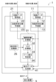
次に、図面を参照して本発明の実施の形態を説明する。図1は、操船支援装置1の電気的構成を示すブロック図である。Next, an embodiment of the present invention will be described with reference to the drawings. Figure 1 is a block diagram showing the electrical configuration of the ship
まず、第1実施形態について説明する。図1に示す第1実施形態の操船支援装置1は、水上を移動する船舶に設けられる。First, the first embodiment will be described. The ship
操船支援装置1には、表示装置5が接続される。表示装置5は、例えば液晶ディスプレイとして構成され、操船を支援する情報を表示する。操船支援装置1は、衝突危険ゾーンと、警戒ゾーンと、を表示装置5に表示するための表示データを生成し、当該表示装置5に出力する。A
衝突危険ゾーンとは、自船と他船との衝突が将来的に発生する可能性が高いゾーンである。警戒ゾーンとは、衝突の可能性は低いが、自船との関係で設定したプ ライベート領域に他船が将来的に侵入する可能性が高いゾーンである。これらのゾーンは、自船の変針に対して、他船に妨害される領域を当該他船の予定針路上 に示したもの(OZT)であり、上記の非特許文献1とは異なる方法で計算される。なお、衝突危険ゾーン及び警戒ゾーンの詳細については後述する。
A collision danger zone is a zone where there is a high possibility of a collision occurring between your ship and another ship in the future. A warning zone is a zone where there is a low possibility of a collision, but there is a high possibility that another ship will intrude into a private area set in relation to your ship in the future. These zones are areas on the other ship's planned course where the ship may be obstructed by another ship when changing course (OZT), and are calculated using a different method than that described in
この操船支援装置1は、他船データ処理部11と、自船データ処理部21と、設定長さ記憶部26と、計算処理部31と、表示データ生成部41と、を備える。
This ship
具体的に説明すると、操船支援装置1は公知のコンピュータとして構成されており、CPU、ROM、RAM等を備える。ROMには、上記の衝突危険ゾーン及 び警戒ゾーンの表示データを生成するためのプログラムが記憶される。上記のハードウェアとソフトウェアの協働により、操船支援装置1を、他船データ処理部 11、自船データ処理部21、設定長さ記憶部26、計算処理部31、及び表示データ生成部41等として動作させることができる。
To be more specific, the ship
他船データ処理部11は、自船の周りに存在する他船に関し、衝突危険ゾーン及び警戒ゾーンの表示のために必要なデータを取得する。他船データ処理部11は、他船データ取得部12と、他船将来位置予測部13と、を備える。The other ship
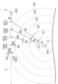
他船データ取得部12は、図2の自船2と他船3との関係で示すように、現在の他船3の位置である他船位置Pr0と、他船3の船速ベクトルである他船船速ベクトルVtと、を取得する。The other ship
具体的に説明すると、図1の操船支援装置1は、自船2の周囲を探知してレーダ映像を生成する図略のレーダ装置と接続されている。このレーダ装置は、探知し た物標(他船3)の動きを検出して追尾する技術であるTT(ターゲットトラッキング)機能を有している。TT機能は公知であるため簡単に説明すると、TT 機能は、過去のレーダ映像の推移に基づいて、自船の周囲に存在する物標(他船3)の位置及び速度ベクトルを計算により取得するものである。
To be more specific, the ship
レーダ装置は、他船3の位置及び速度として、その代表点の位置及び速度を出力する。代表点の位置としては、例えば、レーダ映像に現れる当該他船3のエコー像の図心の位置が用いられる。The radar device outputs the position and speed of the representative point as the position and speed of the
レーダ装置は自船2を基準とした相対的な他船3の位置及び速度を取得するものであるが、他船データ取得部12に入力される他船3の位置及び速度ベクトル は、適宜の手段(例えば、公知のGNSS測位装置及び方位センサ)により得られた自船2の位置及び船首方位に基づいて、対地基準となるように予め変換され ている。他船データ取得部12は、得られた他船位置Pr0及び他船船速ベクトルVtを、探知された物標ごとに他船将来位置予測部13に出力する。The radar device acquires the position and speed of
他船将来位置予測部13は、他船3の将来位置を予測する。得られた他船3の予測位置は、衝突危険ゾーン及び警戒ゾーンをその位置に表示すべきか否かを判定する位置的基準となる。以下の説明では、この位置を判定点と呼ぶことがある。The other ship future
以下、詳細に説明する。他船将来位置予測部13は、図2に示すように、他船3の位置及び速度が得られた時刻である基準時刻T0(具体的には、現在時刻)を 起点として、適宜の時間間隔ΔTをあけて、複数の将来の時刻T1,T2,・・・を定める。そして、他船将来位置予測部13は、基準時刻T0における他船3 の位置及び船速(他船位置Pr0及び他船船速ベクトルVt)に基づいて、上記の将来の時刻T1,T2,・・・での他船位置Pr1,Pr2,・・・を予測す る。予測により求められた他船位置Pr1,Pr2,・・・が、判定点D1,D2,・・・となる。
A detailed explanation is given below. As shown in Figure 2, the other ship future
他船位置 Pr1,Pr2,・・・(判定点D1,D2,・・・)を求めるとき、他船将来位置予測部13は、基準時刻T0で取得した他船船速ベクトルVtの大きさ及び 向きを何れも一定に保ったまま、他船3が他船位置Pr0から移動すると仮定する。即ち、他船3は、基準時刻T0と同じ針路及び同じ船速で航行を継続すると みなされる。従って、他船位置Pr1,Pr2,・・・を簡単に求めることができる。
When determining the other ship positions Pr1, Pr2, ... (judgment points D1, D2, ...), the other ship future
他船位置Pr1,Pr2,・・・は、 図2に示すように、他船位置Pr0から他船船速ベクトルVtを延長した直線である針路C上に、適宜の間隔で並ぶように定められる。図2の例では他船位置 Pr1,Pr2,・・・が等間隔で並んでいるが、これは一例であり、詳細は後述する。他船将来位置予測部13は、取得した他船位置Pr1,Pr2,・・・ (判定点D1,D2,・・・)の位置を示すデータを、計算処理部31及び表示データ生成部41に出力する。
As shown in Figure 2, the other ship positions Pr1, Pr2, ... are determined to be lined up at appropriate intervals on course C, which is a straight line extending the other ship speed vector Vt from the other ship position Pr0. In the example of Figure 2, the other ship positions Pr1, Pr2, ... are lined up at equal intervals, but this is just one example and details will be described later. The other ship future
自船データ処理部21は、自船2に関し、衝突危険ゾーン及び警戒ゾーンの表示のために必要なデータを取得する。自船データ処理部21は、自船データ取得部22と、自船将来位置予測部23と、を備える。The own ship
自船データ取得部22には、自船の位置である自船位置P0と、自船船速ベクトルVと、に関するデータが入力される。
Data regarding the ship's own position P0, which is the ship's position, and the ship's own speed vector V are input to the ship's own
自船位置P0は、現在の自船2の位置である。操船支援装置1には図略のGNSS測位装置が接続されており、自船データ取得部22は、GNSS測位装置から入力される測位結果に基づいて、自船2の位置である自船位置P0を取得することができる。The own ship position P0 is the current position of the
自船船速ベクトルVは、現在の自船2の船速である。自船データ取得部22は、GNSS測位装置から得られる位置の変化を計算することにより、自船2の船速である自船船速ベクトルVを取得することができる。The own ship speed vector V is the current ship speed of the
自船位置P0及び自船船速ベクトルVは、自船2の代表点、具体的には、図略のGNSSアンテナが取り付けられる場所の位置及び速度を意味する。自船データ取得部22は、得られた自船位置P0及び自船船速ベクトルVを、自船将来位置予測部23に出力する。The ship's own position P0 and ship's own speed vector V refer to the position and speed of the representative point of the
自船将来位置予測部23は、前述の他船将来位置予測部13で説明した複数の時刻T1,T2,・・・における自船の将来位置を予測する。予測されたそれぞれ の自船位置P1,P2,・・・は、各時刻T1,T2,・・・で他船将来位置予測部13が予測した他船位置Pr1,Pr2,・・・に対応する。The own ship future
自船位置P1,P2,・・・を求めるとき、自船将来位置予測部23は、基準時刻T0で取得した自船船速ベクトルVの大きさは一定である一方、自船船速ベク トルVの向きは基準時刻T0で任意の向きに変化し、それ以後は一定の向きで、自船2が自船位置P0から航行を継続すると仮定する。即ち、自船2は、自船位 置P0において針路を任意に定めるが、その後は当該針路で、かつ同じ船速で航行を継続するとみなされる。従って、推定される自船位置P1,P2,・・・は 何れも、基準時刻T0における自船位置P0を中心とする同心円上に位置する。When determining own ship's positions P1, P2, ..., the own ship future
図2には、自船位置P1,P2,・・・につ いて、多数推定される位置の一部を小さな丸印で示している。予測された自船位置P1,P2,・・・が並ぶ円(以下、自船位置候補円E1,E2,・・・と呼 ぶことがある。)の半径は、基準時刻T0から各時刻T1,T2,・・・までの時間と、自船船速ベクトルVの大きさと、の積に等しい。In Figure 2, some of the many estimated positions of the ship's own position P1, P2, ... are indicated by small circles. The radius of the circle in which the predicted ship's own position P1, P2, ... are arranged (hereinafter referred to as the ship's own position candidate circle E1, E2, ...) is equal to the product of the time from the reference time T0 to each time T1, T2, ... and the magnitude of the ship's own speed vector V.
このようにして、図1の自船将来位置予測部23は、各時刻T1,T2,・・・における自船位置候補円E1,E2,・・・を求める。自船将来位置予測部23 は、自船位置候補円E1,E2,・・・に関するデータを、予測した自船位置P1,P2,・・・として計算処理部31に出力する。In this way, the ship's future
設定長さ記憶部26は、自船長さLと、プライベート長さPLと、を記憶する。
The set
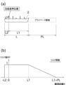
自船長さLは、図3(a)に示すように、自船2の前後方向の全長である。自船長さLは、自船2の前後方向での物理的な大きさを示す。本実施形態では、この 自船長さLの範囲に他船3が存在すると、自船2と他船3とで衝突が生じると考える。なお、自船データ取得部22が取得する自船位置P0、及び自船将来位置 予測部23が予測する自船位置P1,P2,・・・は、上述のGNSSアンテナの船体への取付位置を意味するが、この位置(上述の代表点。以下、自船基準位 置という。)は、通常、自船長さLの中途部にある。従って、自船長さLのパラメータは、上記の自船基準位置から船首までの長さL1と、当該自船基準位置か ら船尾までの長さL2と、の組合せとなっている。2つの長さL1,L2は、事前に操船支援装置1に適宜設定される。
As shown in FIG. 3(a), the ship's length L is the total length of the ship's 2 in the fore-aft direction. The ship's length L indicates the physical size of the ship's 2 in the fore-aft direction. In this embodiment, it is considered that if another
プラ イベート長さPLは、上記の自船長さLには含まれていないために自船2と他船3の物理的な接触は生じないものの、他船3の侵入が心理的に好ましくないと操 船者が感じるプライベート領域(警戒領域)の、前後方向での長さを意味する。プライベート領域は、人と人との間の距離を考えるときに、自分の正面又は背後 に他人がこれ以上近づくと警戒心を生じるパーソナルエリアに例えることができる。プライベート長さPLは、自船長さLの前側及び後側の少なくとも何れか に、操船者によって任意の長さで設定される。例えば、操船者は、自船長さLの前側に、長さが0.5海里のプライベート長さPLを設定することができる。
The private length PL means the length in the fore-aft direction of the private area (warning area) where the ship operator feels that the intrusion of the
図1に示す設定長さ記憶部26は、記憶する自船長さL、プライベート長さPLを、計算処理部31に出力する。The set
次に計算処理部31について説明する。計算処理部31は、他船データ処理部11及び自船データ処理部21から出力されるデータを利用して、前述の判定点D1,D2,・・・のそれぞれにおいて衝突危険ゾーン又は警戒ゾーンを表示するか否かを、計算により判定する。Next, we will explain the
計算処理部31は、離隔距離計算部32と、リスク計算部33と、ゾーン表示判定部34と、を備える。
The
離隔距離計算部32は、将来の各時刻T1,T2,・・・で、到達することが予測される他船位置Pr1,Pr2,・・・と、対応する自船位置P1,P2,・・・と、の間の距離である離隔距離R1,R2,・・・を計算する。The separation
離隔距離R1,R2,・・・は衝突の危険性を評価するためのものであるので、予測される様々なケースのうち、自船2と他船3が最も接近するケースを考える ことが合理的である。そこで、例えば時刻T1の離隔距離R1を計算するにあたっては、離隔距離計算部32は、当該時刻T1において多数予測される自船位置 P1のうち、当該時刻T1における他船位置Pr1に最も近くなる位置を選択する。Since the separation distances R1, R2, ... are used to evaluate the risk of collision, it is reasonable to consider the case in which the
図2には、予測された多数の自船位置P1の中から、離隔距離R1の計算のために選択される自船位置P1を、黒塗りの丸印で示している。離隔距離R1は、自船位置P1のうち黒塗りの丸印となっている位置と、他船位置Pr1と、の間の距離として計算される。In Figure 2, the ship's own position P1 selected from the many predicted ship's own positions P1 for calculating the separation distance R1 is shown with a black circle. The separation distance R1 is calculated as the distance between the ship's own position P1 indicated by a black circle and the other ship's position Pr1.
時刻T1を例に考えると、離隔距離R1は、自船位置候補円E1上の点と、他船位置Pr1と、の距離の最小値を意味する。時刻T1の離隔距離R1は、当該時 刻T1における他船位置Pr1と、基準時刻T0における自船位置P0(自船位置候補円E1の中心)と、の間の距離を求め、この距離から自船位置候補円E1 の半径を減算することで、容易に求めることができる。他の時刻T2,・・・における離隔距離R2,・・・も同様である。Taking time T1 as an example, separation distance R1 means the minimum distance between a point on the own ship's position candidate circle E1 and the other ship's position Pr1. Separation distance R1 at time T1 can be easily calculated by determining the distance between the other ship's position Pr1 at that time T1 and the own ship's position P0 (the center of the own ship's position candidate circle E1) at reference time T0, and subtracting the radius of the own ship's position candidate circle E1 from this distance. The same applies to separation distances R2, ... at other times T2, ...
このように、離隔距離計算部32は、自船2及び他船3の船速を一定とみなして、予測された自船2の将来位置と他船3の将来位置との間の距離である離隔距離Rnを計算する。従って、単純な幾何学的な計算で離隔距離Rnを取得することができる。In this way, the separation
離隔距離Rnは上記の計算方法によって求められるので、値が正だけでなく負にもなり得る。離隔距離Rnが正の場合は、自船位置Pnが、他船位置Prnより も、基準時刻T0における自船位置P0に近いことを意味する。離隔距離Rnが負の場合は、自船位置Pnが、他船位置Prnよりも、基準時刻T0における自 船位置P0から遠いことを意味する。図2の例では、離隔距離R1,R2,R3,R4は正となり、離隔距離R5は負となる。 Because the separation distance Rn is calculated using the above method, the value can be positive as well as negative. When the separation distance Rn is positive, it means that the ship's position Pn is closer to the ship's position P0 at the reference time T0 than the other ship's position Prn. When the separation distance Rn is negative, it means that the ship's position Pn is farther from the ship's position P0 at the reference time T0 than the other ship's position Prn. In the example of Figure 2, separation distances R1, R2, R3, and R4 are positive, and separation distance R5 is negative.
離隔距離Rnが正の場合は、自船2と他船3が最も接近するケースにおいて、他船3が自船2の船首側にあることを示す。離隔距離Rnが負の場合は、自船2と他船3が最も接近するケースにおいて、他船3が自船2の船尾側にあることを表す。
When the separation distance Rn is positive, it indicates that in the case where the
本実施形態においては、離隔距離計算部32が離隔距離Rnを計算する段階では、自船2及び他船3は何れも点として扱われ、物理的な大きさが考慮されていない。離隔距離Rnは、自船2の代表点である自船基準位置と、他船3の代表点と、の距離として表される。In this embodiment, at the stage when the separation
図1のリスク計算部33は、衝突危険ゾーン及び警戒ゾーンを表示するか否かを判断するためのパラメータであるリスク値(衝突リスク値、警戒リスク 値)RPnを計算する。詳細には、リスク計算部33は、予め定められたリスク関数FRを利用して、離隔距離計算部32により計算されたそれぞれの離隔距離 Rnを、リスク値RPnに換算する。リスク値RPnは0以上1以下の値であり、0は自船2と他船3とで衝突の可能性がないことを示し、1は自船2と他船3 とが衝突することを示す。The
リスク計算部33が計算に用いるリスク関数FRは、設定長さ記憶部26の記憶内容を参照して定 められる。図3(b)には、本実施形態で用いるリスク関数FRが、図3(a)の自船基準位置を原点とし、横軸に離隔距離Rをとり、縦軸にリスク値RPを とったグラフにより示されている。The risk function FR used by the
図3(b)に示すように、離隔距離Rが自船長さLに対応する範囲(-L2≦R≦L1の 範囲)にあるとき、リスク関数FRの値は1となる。また、離隔距離Rがプライベート長さPLに対応する範囲(L1<R<L1+PL)にあるとき、リスク関 数FRの値は0よりも大きく1よりも小さい値をとり、かつ、その値は、離隔距離Rが増加するに従って単調に減少する。離隔距離Rが自船長さLにもプライ ベート長さPLにも対応しない範囲(R<-L2、又は、R≧L1+PL)にあるとき、リスク関数FRの値は0となる。As shown in Figure 3 (b), when the separation distance R is in the range corresponding to own ship's length L (-L2≦R≦L1), the value of the risk function FR is 1. Also, when the separation distance R is in the range corresponding to the private length PL (L1<R<L1+PL), the value of the risk function FR is greater than 0 and less than 1, and the value monotonically decreases as the separation distance R increases. When the separation distance R is in the range that does not correspond to either own ship's length L or private length PL (R<-L2, or R≧L1+PL), the value of the risk function FR is 0.
このように、本実施形態では、離隔距離Rが自船長さLに相当する範囲で値が1になるリスク関数FRを用いて、リスク計算部33がリスク値RPを計算する。従って、自船の物理的な長さを考慮して、衝突の可能性を評価することができる。In this way, in this embodiment, the
リスク計算部33は、上記のリスク関数FRに離隔距離R1,R2,・・・を代入して取得したリスク値RP1,RP2,・・・を、ゾーン表示判定部34に出力する。
The
ゾーン表示判定部34は、それぞれの判定点D1,D2,・・・において、衝突危険ゾーンを表示すべきか、警戒ゾーンを表示すべきか、何れも表示しないかを、リスク計算部33から出力されるリスク値RP1,RP2,・・・に従って判定する。The zone
具体的には、ゾーン表示判定部34は、リスク計算部33から出力されるリスク値RPnが1である場合は、衝突危険ゾーンを表示する必要があると判定する。 ゾーン表示判定部34は、リスク値RPから出力されるリスク値RPが1より小さいが0より大きい場合は、警戒ゾーンを表示する必要があると判定する。ゾー ン表示判定部34は、リスク値RPが0である場合は、衝突危険ゾーン及び警戒ゾーンの何れも表示する必要がないと判定する。Specifically, when the risk value RPn output from the
このように、本実施形態の計算処理部31では、従来のOZTで用いられているように速度の誤差を考慮して確率分布を計算しない。即ち、計算処理部31は、 自船船速ベクトルV及び他船船速ベクトルVtに誤差がないものと考えた上で、単純に、離隔距離Rnで示される自船2の基準位置と他船3の代表点との位置関 係が自船長さLの範囲に含まれるか否か、又は、プライベート長さPLの範囲に含まれるか否かに基づいて、衝突危険ゾーン及び警戒ゾーンの表示の要否を判断 している。従って、判断に必要な計算量を著しく減らすことができる。
In this way, the
次に、表示データ生成部41について説明する。図4は、図2の状況における衝突危険ゾーン91及び警戒ゾーン92の表示例を示す図である。図5は、本実施形態による衝突危険ゾーン91及び警戒ゾーン92の表示を、従来のOZTの表示と比較して示す図である。Next, the display
表示データ生成部41は、操船者を支援するための情報を表示装置5に表示させるための表示データを生成し、適宜のインタフェースを介して表示装置5に出力する。The display
図4には、表示装置5における表示画面の例が示されている。表示データ生成部41は、図4に示すように、自船2の位置及び速度、他船3の位置及び速度等を 図形で示す表示データを生成する。表示データ生成部41は、更に、ゾーン表示判定部34の判定結果に応じて、それぞれの判定点D1,D2,・・・に、衝突 危険ゾーン91又は警戒ゾーン92を表示させる。
Figure 4 shows an example of a display screen on the
図4には、図2の状況において、離隔距離R4に対応するリスク値RP4が1であり、離隔距離R3に対応するリスク値が0.3であり、他の離隔距離R1,R2,R5に対応するリスク値は何れも0だった場合の、表示装置5の表示例を示している。
Figure 4 shows an example of the display on the
図4に示すように、判定点D4には、衝突危険ゾーン91を示す図形が表示され、判定点D3には、警戒ゾーン92を示す図形が表示される。他の判定点 D1,D2,D5には、図形は表示されていない。なお、判定点D1,D2,・・・は計算の基準として用いられる点であるため、説明のために図4には描かれ ているが、実際には画面に表示されない。As shown in Figure 4, a graphic representing a
衝突危険ゾーン91及び警戒ゾーン92は、判定点Dnを中心とする円の図形として表示される。円の大きさは、小さくなり過ぎないように適宜定められる。例えば、円の大きさは、その直径が自船長さLと等しくなるように定めることができる。
The
互いに隣り合う2つの判定点Dnのそれぞれに例えば衝突危険ゾーン91の円の図形を表示したときに、円と円の間に隙間が生じるのは好ましくない。このた め、上述の他船将来位置予測部13が判定点Dnを求めるときの時間間隔ΔTは、図形の円の大きさと、他船船速ベクトルVtの大きさと、を考慮して、隣り合 う判定点Dn同士の距離を十分に短くできるように定められる。これにより、衝突危険ゾーン91又は警戒ゾーン92の表示の領域的な連続性を確保することが できる。
When, for example, a circular diagram of the
操船支援装置1に入力される自船位置P0、自船船速ベクトルV、他船位置Pr0、及び他船船速ベクトルVtは、 何れも刻々と変化し、それに応じて衝突危険ゾーン91及び警戒ゾーン92の表示をリアルタイムで更新する必要がある。また、自船2の周囲に他船3が1つだ けでなく複数存在する場合も考えられ、この場合は、それぞれの他船3について衝突危険ゾーン91及び警戒ゾーン92の表示処理を行わなければならない。 従って、処理に必要な計算負荷を軽減することが重要である。The own ship's position P0, own ship's speed vector V, other ship's position Pr0, and other ship's speed vector Vt input to the ship
他船将来位置予測部13は、判定点Dnを理論上無限に生成す ることができるが、判定点Dnが多数になると計算負荷が重くなる。そこで、本実施形態では、所定の判定限界距離を定め、他船将来位置予測部13が出力する 判定点Dnの位置を、他船位置Pr0から判定限界距離以内に限定している。これにより、計算負荷が過大にならないようにすることができる。The other ship future
ただし、本実施形態では、各判定点Dnにおいて衝突危険ゾーン91及び警戒ゾーン92を表示すべきか否かを判定するのに必要な計算量が、上述したように従 来と比べて軽減されている。従って、隣り合う判定点Dnの間の距離を短くしたり、前記判定限界距離を長くしたりして、多数の判定点Dnが生成された場合で も、リアルタイムで問題なく処理を行うことができる。これにより、衝突危険ゾーン91及び警戒ゾーン92が表示される分解能を高めることができ、又は、よ り先の将来予測に基づく衝突危険ゾーン91及び警戒ゾーン92の表示を行うことができる。However, in this embodiment, the amount of calculation required to determine whether or not the
表示データ生成部41が生成す る表示データでは、衝突危険ゾーン91と警戒ゾーン92とで、表示装置5で表示される色彩を異ならせるようにすることができる。図4では、図面での表現の 都合上、衝突危険ゾーン91と警戒ゾーン92とで表示色が異なることを実線と破線とで示している。これにより、操船者は、他船3との衝突が発生する可能性 が高い領域と、衝突はしないが前述のプライベート長さPLに他船3が入ってしまう可能性が高い領域と、を明確に区別して把握することができるので、状況を 容易に理解することができる。In the display data generated by the display
なお、表示装置において衝突危険ゾーン91と警戒ゾーン92とでどのように表示を変えるか については、色を変えることに限定されない。例えば、衝突危険ゾーン91と警戒ゾーン92とで、内部の塗り潰しの有無、塗り潰し部分の透明度や模様を変え るように表示させることができる。図4に描かれているとおり、ゾーンの図形の輪郭線を実線と破線等とで異ならせても良い。また、ゾーンの図形に文字、記 号、又は小さなマーク等を付加することによって、操船者が衝突危険ゾーン91と警戒ゾーン92とを区別できるように構成してもよい。It should be noted that the manner in which the
警戒ゾーン92はリスク値RPが0よりも大きく1よりも小さい場合に対応するが、表示データ生成部41は、警戒ゾーン92に関して、リスク値RPの大きさ に応じて表示の態様を異ならせる表示データを生成してもよい。例えば、リスク値RPが小さくなるにつれて、表示される警戒ゾーン92の輪郭線又は内部の塗 り潰しの透明度を徐々に増加させることが考えられる。また、衝突危険ゾーン91を赤色で表示するとともに、警戒ゾーン92を、リスク値RPが小さくなるに つれて、赤色から黄色へ徐々に変化するように色を変化させて表示しても良い。The
警戒ゾーンの表示は、リスク値RPが0より大きく1より小さい場合に一律に表示することに代えて、操船者によって設定された所定の閾値よりもリスク値RPが大きい場合にのみ行われても良い。これにより、操船者の好みに応じた表示を実現することができる。 Instead of displaying the warning zone uniformly when the risk value RP is greater than 0 and less than 1, the warning zone may be displayed only when the risk value RP is greater than a predetermined threshold value set by the operator. This allows the display to be tailored to the operator's preferences.
なお、衝突危険ゾーン91と警戒ゾーン92とを、全く同じ態様で表示することもできる。
In addition, the
上述したように、本実施形態では、リスク関数FRにおいて、自船長さLを考慮した衝突危険性の評価が行われる。即ち、自船2を、点として扱うのではなく、 前後方向に自船長さLだけ細長い直線として扱っている。従って、例えば自船長さLが相当に長い大型船舶である場合でも、衝突の危険が高い領域を、実際の船 舶の大きさを考慮して妥当な位置に表示することができる。As described above, in this embodiment, the risk function FR evaluates the risk of collision taking into account the ship's length L. That is, the
図5には、同じ状況下で、本実施形態の衝突危険ゾーン91と、 従来のOZTと、の表示の比較が示されている。図5(a)で示すように、本実施形態の衝突危険ゾーン91は、自船長さLを考慮することで、図5(b)で示 す従来のOZTよりも、他船3に近い側にゾーンの領域が拡がっている(拡張部分91e)。この表示は、実際の自船長さLを考慮すると、他船3との衝突を避 けるには、従来のOZTと重複する部分だけでなく、それから拡がっている拡張部分91eにも自船2を操船すべきでないことを示している。
Figure 5 shows a comparison of the display of the
図5(a)に示す本実施形態の表示例では、プライベート長さPLを自船2の前方に設定したことに伴う警戒ゾーン92が、衝突危険ゾーン91よりも他船3に 近い側に表示される。この表示は、警戒ゾーン92に操船すると、自船2の前方のプライベート長さPLに相当する領域に他船3が入ってしまう可能性が高いこ とを示している。In the display example of this embodiment shown in Figure 5 (a), a
なお、図5(a)に示す本実施形態の表示例では、図5(b)に示す従来のOZTの左端の円に相当する場 所N1には、衝突危険ゾーン91が表示されていない。これは、本実施形態では、自船長さLのうち自船基準位置よりも船尾側の部分の長さL2が相当に短く、 これをリスク計算部33が適切に考慮した結果である。図5(a)の例は自船2の後方にプライベート長さPLが設定されていない場合を示しているが、後方の プライベート長さPLを適宜設定すれば、上記の場所N1に警戒ゾーン92が表示されることになる。
In the display example of this embodiment shown in Figure 5(a), the
上記の説明では、レー ダ装置が備えるレーダアンテナの位置が、GNSS測位装置のGNSSアンテナの位置(言い換えれば、自船基準位置)と同一であるとみなして、衝突危険性の 評価を行っている。しかしながら、レーダアンテナの取付位置とGNSSアンテナの取付位置との距離が無視できない場合は、他船データ取得部12が取得する 他船位置を、GNSSアンテナの位置が基準となるように再計算すると、より正確な衝突計算が可能になる点で好ましい。一方で、自船基準位置を、GNSSア ンテナの位置ではなく、レーダアンテナの位置と一致するように定めても良い。この場合は、他船データ処理部11が取得する自船位置等を、レーダアンテナの 位置が基準となるように再計算することになる。In the above explanation, the collision risk is evaluated assuming that the position of the radar antenna equipped in the radar device is the same as the position of the GNSS antenna of the GNSS positioning device (in other words, the ship's own reference position). However, if the distance between the mounting position of the radar antenna and the mounting position of the GNSS antenna cannot be ignored, it is preferable to recalculate the other ship's position acquired by the other ship
以上に説明したように、本実施形態の操船支援装置1は、他船データ取得部 12と、他船将来位置予測部13と、自船データ取得部22と、自船将来位置予測部23と、リスク計算部33と、表示データ生成部41と、を備える。他船 データ取得部12は、他船3の位置及び速度に関する情報(他船位置Pr0及び他船船速ベクトルVt)を取得する。他船将来位置予測部13は、他船データ取 得部12が取得した他船位置Pr0及び他船船速ベクトルVtに基づいて、当該他船3が同じ針路で、かつ同じ船速で航行を継続した場合に、将来の複数の時刻 T1,T2,・・・における他船位置Pr1,Pr2,・・・を予測する。自船データ取得部22は、自船2の位置及び速度に関する情報(自船位置P0及び自 船船速ベクトルV)を取得する。自船将来位置予測部23は、自船データ取得部22が取得した自船位置P0及び自船船速ベクトルVに基づいて、自船2が当該 自船位置P0で任意に定めた針路で、かつ同じ船速で航行を継続した場合に、他船将来位置予測部13によって予測された他船位置Pr1,Pr2,・・・と対 応する自船位置P1,P2,・・・を予測する。リスク計算部33は、それぞれの時刻T1,T2,・・・で予測された他船位置Pr1,Pr2,・・・と、対 応して予測された自船位置P1,P2,・・・と、の間の離隔距離R1,R2,・・・に基づいて、自船2と他船3との衝突が将来的に発生する可能性が高い ゾーンである衝突危険ゾーン91を表示するか否かを判断ためのリスク値RPを計算する。表示データ生成部41は、リスク値RPを用いた判断に基づいて、予 測された他船位置Pr1,Pr2,・・・に衝突危険ゾーン91を表示するための表示データを生成する。As described above, the ship
これにより、自船 2の大きさ、及び、自船2と他船3の離隔距離R1,R2,・・・を利用して、自船2と他船3の衝突が将来的に発生するゾーンである衝突危険ゾーン91を表 示装置5に表示させることができる。即ち、自船2の大きさが考慮されているので、より妥当性が高い、操船者の実際の操船感覚にマッチした衝突危険ゾーン 91を表示することができる。また、従来のように速力誤差の発生を考慮して自船と他船の同時存在確率を計算するのではなく、自船2と他船3との離隔距離 R1,R2,・・・を基準として衝突危険ゾーン91の表示判定が行われるので、計算負荷を著しく軽減することができる。This allows the
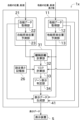
次に、第2実施形態を説明する。図6は、第2実施形態の操船支援装置1xの電気的構成を示すブロック図である。なお、第2実施形態の説明においては、前述の第1実施形態と同一又は類似の部材には図面に同一の符号を付し、説明を省略する場合がある。Next, the second embodiment will be described. Figure 6 is a block diagram showing the electrical configuration of the ship
図6に示す第2実施形態の操船支援装置1xでは、他船データ取得部12が、他船3の位置及び速度の情報を、レーダ装置ではなくAIS装置から取得する。 AIS装置は、複数の船舶の航行情報を交換するための船舶自動識別装置であって、他船3の位置、対地速度、船名、船の長さと幅、測位アンテナの位置等の データを取得することができる。In the second embodiment of the ship
他船データ取得部12は、他船3の位置及び速度だけでなく、他船3の長さ及び測位アンテ ナの前後方向での位置の情報も取得する。他船データ取得部12は、他船3の長さ及び測位アンテナの位置の情報に基づき、他船3の測位アンテナの位置から船 首までの長さと、測位アンテナの位置から船尾までの長さと、をリスク計算部33に出力する。The other ship
リスク計算部33は、設定長 さ記憶部26から取得した自船長さL及びプライベート長さPLと、他船データ取得部12から取得した他船の長さと、を利用して、リスク値RPを計算する。 本実施形態で用いられるリスク関数FRとしては、図3(b)のグラフに対して、リスク値RPが1になる離隔距離Rの領域を、他船3の長さを考慮して自船2 の前後方向に適宜拡張するように変更したものを用いれば良い。The
本実施形態では、自船2だけでなく他船3についても、点でなく、その長さだけ前後方向に細長い直線として扱って、衝突の可能性を評価している。従って、衝突危険ゾーン91及び警戒ゾーン92の表示を、操船者の実際の操船感覚に一層整合させたものとすることができる。In this embodiment, the possibility of collision is evaluated by treating not only the
AISにより得られる他船3の情報には、他船3の大きさに関する情報が含まれない場合もある。この場合、リスク計算部33は、他船3の長さを、操船者が事前に適宜設定した長さと等しいものと一律にみなして、リスク値RPを計算することができる。The information about the
以上に本発明の好適な実施の形態を説明したが、上記の構成は例えば以下のように変更することができる。 Although a preferred embodiment of the present invention has been described above, the above configuration can be modified, for example, as follows:
他船位置Pr0の針路C上に他船将来位置予測部13が定める他船位置Pr1,Pr2,・・・(判定点D1,D2,・・・)は、図2のように等間隔で並ぶこ とに限定されず、不等間隔とすることもできる。例えば、自船2の位置から等角度間隔で放射状に広がる複数の仮想直線を考え、それぞれの仮想直線と上記の針 路Cとが交わる位置に、他船位置Pr1,Pr2,・・・が定められても良い。このとき、自船2の現在の針路に近い仮想直線(例えば、自船2の針路から左右 10°以内の仮想直線)の角度間隔が、そうでない仮想直線の角度間隔よりも小さくなるように、複数の仮想直線を配置することができる。この場合、自船2の 現在の針路に干渉し易い領域で判定点D1,D2,・・・を密に定めることができるので、自船2の予定針路近傍において衝突危険ゾーン及び警戒ゾーンを表示 する空間分解能を高めることができる。The other ship positions Pr1, Pr2, ... (judgment points D1, D2, ...) determined by the other ship future
上述のとおり、他船位置Pr1,Pr2,・・・は、複数の将来の時刻T1,T2,・・・に対応している。従って、他船位置Pr1,Pr2,・・・をどのように定めるかに応じて、対応するそれぞれの自船位置候補円E1,E2,・・・の大きさも変化することになる。As described above, the other ship positions Pr1, Pr2, ... correspond to multiple future times T1, T2, .... Therefore, depending on how the other ship positions Pr1, Pr2, ... are determined, the size of each corresponding own ship position candidate circle E1, E2, ... will also change.
自船基準位置は、上記の実施形態で説明した位置に限定されず、自船2における任意の点に定めることができる。例えば、自船基準位置を、自船2が回頭しているときの軸となる位置(船体運動における転心の位置)とすることができる。The ship's own reference position is not limited to the position described in the above embodiment, but can be set to any point on the ship's own 2. For example, the ship's own reference position can be the position that serves as the axis when the ship's own 2 is turning (the position of the pivot point in the ship's motion).
実際の操船では、高速航行時は低速航行時と比較して、前方のより遠くの他船3にも注意を払うべきである。これを考慮して、自船2の特に前側に設定されるプライベート長さPLが、自船船速ベクトルVの大きさに応じて自動的に変化するように構成されていても良い。In actual ship maneuvering, when sailing at high speed, attention should be paid to
第2実施形態において、他船データ処理部11は、AISでなく、第1実施形態で説明したレーダ装置において、TT機能で追尾されるエコー像の形状から取得された他船3の長さを取得するように構成することもできる。In the second embodiment, the other ship
自船2の長さだけでなく幅を考慮して、衝突危険ゾーン91の表示を判定することもできる。プライベート領域の長さだけでなく幅を考慮して、警戒ゾーン92の表示を判定することもできる。同様に、他船3の長さだけでなく幅を考慮することもできる。
It is also possible to determine whether to display the
衝突危険ゾーン91を表示するか否かを判定するためのリスク値(衝突リスク値)と、警戒ゾーン92を表示するか否かを判定するためのリスク値(警戒リスク値)は、共通のリスク関数FRでなく、別々の関数で求めても良い。The risk value (collision risk value) for determining whether or not to display the
衝突危険ゾーン91及び警戒ゾーン92は、それぞれ任意の態様で表示することができる。例えば、判定点Dnを中心とする円に代えて、判定点Dn同士を結ぶ線で表示されてもよい。そして、当該線の太さは、適宜に設定することができる。The
リスク関数FRにおいて、プライベート長さPLにおけるリスク値RPは、図3(b)に示すように直線的に減少するのに代えて、例えば曲線的に減少しても良い。In the risk function FR, the risk value RP at the private length PL may decrease, for example, curvedly instead of linearly as shown in Figure 3(b).
第1実施形態において計算処理部31は、リスク計算部33が、自船2の物理的な大きさを考慮してリスク値RPを計算している。これに代えて、離隔距離計算 部32が離隔距離Rnを計算する段階で、自船2の物理的な大きさが考慮されても良い。例えば、離隔距離計算部32が、自船基準位置から船首までの長さL1 を考慮して、予測される他船3の代表点の位置と、予測される将来の自船2の船首の先端位置と、の間の距離の最小値を離隔距離Rnとして計算することが考え られる。In the first embodiment, the
操船支援装置1が、表示装置5を一体的に備えていても良い。The ship
1 操船支援装置
11 他船データ処理部
32 離隔距離計算部
33 リスク計算部
41 表示データ生成部
REFERENCE SIGNS
Claims (7)
前記他船データ取得部が取得した他船の位置及び速度に基づいて、当該他船が同じ針路で、かつ同じ船速で航行を継続した場合に、将来の複数の時刻における他船の位置を予測する他船将来位置予測部と、
自船の位置及び速度に関する情報を取得する自船データ取得部と、
前記自船データ取得部が取得した自船の位置及び速度に基づいて、自船が当該位置で任意に定めた針路で、かつ同じ船速で航行を継続した場合に、前記他船将来位置予測部によって予測された前記他船の位置と対応する自船の位置を予測する自船将来位置予測部と、
それぞれの前記時刻で予測された前記他船の位置と、当該時刻において複数予測される前記自船の位置のうち、当該時刻における前記他船の位置に最も近くなる自船の位置と、の間の離隔距離に基づいて、自船と前記他船との衝突が将来的に発生する可能性が高いゾーンである衝突危険ゾーンを表示するか否かを判断するための衝突リスク値を計算するリスク計算部と、
前記衝突リスク値を用いた判断に基づいて、予測された前記他船の位置に前記衝突危険ゾーンを表示するための表示データを生成する表示データ生成部と、
を備え、
前記リスク計算部は、自船の物理的な大きさと、自船の前側及び/又は後側に設定することができる警戒領域の大きさと、を考慮して、前記離隔距離に基づいて、前記警戒領域に他船が将来的に侵入する可能性が高いゾーンである警戒ゾーンを表示するか否かを判断するための警戒リスク値を計算可能であり、
前記表示データ生成部は、前記警戒リスク値を用いた判断に基づいて、前記警戒ゾーンを、予測された前記他船の位置に前記衝突危険ゾーンと区別可能に表示するための表示データを生成可能であることを特徴とする操船支援装置。 An other ship data acquisition unit that acquires information regarding the position and speed of other ships;
a future ship position prediction unit that predicts the position of the other ship at a plurality of future times if the other ship continues to navigate on the same course and at the same ship speed based on the position and speed of the other ship acquired by the other ship data acquisition unit;
an own ship data acquisition unit for acquiring information regarding the position and speed of the own ship;
a ship's future position prediction unit that predicts the ship's position corresponding to the position of the other ship predicted by the other ship future position prediction unit, based on the ship's position and speed acquired by the ship's data acquisition unit, if the ship continues to navigate at the same speed and on a course arbitrarily determined at the ship's position;
a risk calculation unit that calculates a collision risk value to determine whether or not to display a collision danger zone, which is a zone where a collision between the ship and the other ship is likely to occur in the future, based on the distance between the position of the other ship predicted at each of the times and the position of the ship that is closest to the position of the other ship at that time among the multiple predicted positions of the ship at that time; and
a display data generating unit that generates display data for displaying the collision danger zone at the predicted position of the other ship based on a judgment using the collision risk value; and
Equipped with
the risk calculation unit is capable of calculating an alert risk value for determining whether or not to display an alert zone , which is a zone where there is a high possibility that another ship will invade the alert zone in the future, based on the separation distance, taking into account the physical size of the ship and the size of the alert zone that can be set in front of and/or behind the ship;
The ship steering assistance device is characterized in that the display data generation unit is capable of generating display data for displaying the warning zone at the predicted position of the other ship in a manner distinguishable from the collision danger zone based on a judgment using the warning risk value.
前記離隔距離は、それぞれの前記時刻で予測された前記他船の位置と、対応して予測された自船の位置と、の間の距離として計算されることを特徴とする操船支援装置。 The ship steering assist device according to claim 1,
A ship steering support device characterized in that the separation distance is calculated as the distance between the predicted position of the other ship at each of the times and the corresponding predicted position of the ship itself.
前記リスク計算部は、前記衝突リスク値を、前記他船の物理的な大きさも考慮して計算することを特徴とする操船支援装置。 The ship steering assist device according to claim 1 or 2,
A ship steering assistance device characterized in that the risk calculation unit calculates the collision risk value taking into account the physical size of the other ship .
前記表示データ生成部は、前記警戒リスク値が所定の閾値以上である場合に、前記警戒ゾーンを表示するための表示データを生成することを特徴とする操船支援装置。 A ship steering assist device according to any one of claims 1 to 3,
The ship steering assistance device is characterized in that the display data generation unit generates display data for displaying the warning zone when the warning risk value is equal to or greater than a predetermined threshold.
前記表示データに基づいて表示される前記衝突危険ゾーンと前記警戒ゾーンは、少なくとも色彩が互いに異なることを特徴とする操船支援装置。 A ship steering assist device according to any one of claims 1 to 4,
The collision danger zone and the warning zone displayed based on the display data are at least different in color from each other.
前記警戒領域の大きさは、自船の船速によって変化することを特徴とする操船支援装置。 A ship steering assist device according to any one of claims 1 to 5,
A ship steering support device, characterized in that the size of the warning area changes depending on the ship's speed.
取得した他船の位置及び速度に基づいて、当該他船が同じ針路で、かつ同じ船速で航行を継続した場合に、将来の複数の時刻における他船の位置を予測し、
自船の位置及び速度に関する情報を取得し、
取得した自船の位置及び速度に基づいて、自船が当該位置で任意に定めた針路で、かつ同じ船速で航行を継続した場合に、予測された前記他船の位置と対応する自船の位置を予測し、
それぞれの前記時刻で予測された前記他船の位置と、当該時刻において複数予測される前記自船の位置のうち、当該時刻における前記他船の位置に最も近くなる自船の位置と、の間の離隔距離に基づいて、自船と前記他船との衝突が将来的に発生する可能性が高いゾーンである衝突危険ゾーンを表示するか否かを判断するための衝突リスク値を計算し、
前記衝突リスク値を用いた判断に基づいて、予測された前記他船の位置に前記衝突危険ゾーンを表示するための表示データを生成する、
操船支援方法において、
を備え、
前記衝突リスク値の計算は、自船の物理的な大きさと、自船の前側及び/又は後側に設定することができる警戒領域の大きさと、を考慮して、前記離隔距離に基づいて、前記警戒領域に他船が将来的に侵入する可能性が高いゾーンである警戒ゾーンを表示するか否かを判断するための警戒リスク値を計算可能であり、
前記表示データの生成は、前記警戒リスク値を用いた判断に基づいて、前記警戒ゾーンを、予測された前記他船の位置に前記衝突危険ゾーンと区別可能に表示するための表示データを生成可能である、
操船支援方法。 Obtain information about the position and speed of other ships,
Based on the acquired positions and speeds of the other ships, predicting the positions of the other ships at multiple future times if the other ships continue to navigate on the same course and at the same speed;
Obtain information about the ship's position and speed,
predicting a position of the ship corresponding to the predicted positions of the other ships if the ship continues to navigate at the same speed and on a course arbitrarily determined at the position based on the acquired position and speed of the ship;
calculating a collision risk value for determining whether or not to display a collision danger zone, which is a zone in which a collision between the ship and the other ship is highly likely to occur in the future, based on a distance between the position of the other ship predicted at each of the times and the position of the ship that is closest to the position of the other ship at that time among the multiple predicted positions of the ship at that time;
generating display data for displaying the collision danger zone at the predicted position of the other ship based on a judgment using the collision risk value;
In the ship-steering assistance method,
Equipped with
The calculation of the collision risk value can take into account the physical size of the ship and the size of the warning area that can be set in front of and/or behind the ship, and based on the separation distance, calculate a warning risk value for determining whether or not to display a warning zone, which is a zone where there is a high possibility that another ship will enter the warning area in the future;
The generation of the display data can generate display data for displaying the alert zone at the predicted position of the other ship in a manner distinguishable from the collision danger zone based on a judgment using the alert risk value.
Navigation aids.
Priority Applications (1)
| Application Number | Priority Date | Filing Date | Title |
|---|---|---|---|
| JP2025020620A JP2025067946A (en) | 2020-01-20 | 2025-02-12 | Maneuvering support device and maneuvering support method |
Applications Claiming Priority (3)
| Application Number | Priority Date | Filing Date | Title |
|---|---|---|---|
| JP2020007183 | 2020-01-20 | ||
| JP2020007183 | 2020-01-20 | ||
| PCT/JP2020/048156 WO2021149447A1 (en) | 2020-01-20 | 2020-12-23 | Maneuvering assistance device |
Related Child Applications (1)
| Application Number | Title | Priority Date | Filing Date |
|---|---|---|---|
| JP2025020620A Division JP2025067946A (en) | 2020-01-20 | 2025-02-12 | Maneuvering support device and maneuvering support method |
Publications (2)
| Publication Number | Publication Date |
|---|---|
| JPWO2021149447A1 JPWO2021149447A1 (en) | 2021-07-29 |
| JP7635162B2 true JP7635162B2 (en) | 2025-02-25 |
Family
ID=76992291
Family Applications (2)
| Application Number | Title | Priority Date | Filing Date |
|---|---|---|---|
| JP2021573027A Active JP7635162B2 (en) | 2020-01-20 | 2020-12-23 | Ship-steering support device and ship-steering support method |
| JP2025020620A Pending JP2025067946A (en) | 2020-01-20 | 2025-02-12 | Maneuvering support device and maneuvering support method |
Family Applications After (1)
| Application Number | Title | Priority Date | Filing Date |
|---|---|---|---|
| JP2025020620A Pending JP2025067946A (en) | 2020-01-20 | 2025-02-12 | Maneuvering support device and maneuvering support method |
Country Status (6)
| Country | Link |
|---|---|
| US (1) | US12473059B2 (en) |
| EP (1) | EP4095030B1 (en) |
| JP (2) | JP7635162B2 (en) |
| KR (1) | KR20220128424A (en) |
| CN (1) | CN114930427B (en) |
| WO (1) | WO2021149447A1 (en) |
Families Citing this family (6)
| Publication number | Priority date | Publication date | Assignee | Title |
|---|---|---|---|---|
| JP2021142788A (en) * | 2020-03-10 | 2021-09-24 | トヨタ自動車株式会社 | Operation support system |
| WO2022085355A1 (en) * | 2020-10-23 | 2022-04-28 | 古野電気株式会社 | Ship monitoring system, ship monitoring method, information processing device, and program |
| WO2022249632A1 (en) * | 2021-05-26 | 2022-12-01 | 古野電気株式会社 | Ship monitoring device, ship monitoring method, and program |
| CN113744569B (en) * | 2021-11-03 | 2022-02-18 | 武汉理工大学 | Autonomous collision avoidance method, system, equipment and storage medium for ships in open water |
| EP4290495A1 (en) | 2022-06-09 | 2023-12-13 | Furuno Electric Co., Ltd. | Obstruction zone generation device and method |
| CN116161198B (en) * | 2023-02-16 | 2025-12-02 | 武汉理工大学 | A multi-sensor wireless acquisition and transmission system and method for ship collision data |
Citations (4)
| Publication number | Priority date | Publication date | Assignee | Title |
|---|---|---|---|---|
| JP2005061893A (en) | 2003-08-08 | 2005-03-10 | Toshima Imazu | Ship navigation support device |
| JP2005289264A (en) | 2004-04-01 | 2005-10-20 | Furuno Electric Co Ltd | Vessel navigation supporting system |
| JP2013028296A (en) | 2011-07-29 | 2013-02-07 | Ship & Ocean Foundation | Ship navigation support device |
| JP2019204396A (en) | 2018-05-25 | 2019-11-28 | 株式会社本間組 | Construction ship operation management system |
Family Cites Families (21)
| Publication number | Priority date | Publication date | Assignee | Title |
|---|---|---|---|---|
| JPS62117100A (en) * | 1985-11-18 | 1987-05-28 | 日本鋼管株式会社 | Refuge navigation judgement aid |
| JPH08235500A (en) * | 1995-02-23 | 1996-09-13 | Oki Electric Ind Co Ltd | Collision prevention support device |
| US5860605A (en) * | 1996-10-11 | 1999-01-19 | Johannes Petrus Andreas Josephus Van Der Zanden | Method and device for synchronously making material collide |
| JP4055915B2 (en) * | 1997-10-23 | 2008-03-05 | 日本無線株式会社 | Automatic collision prevention assist device |
| US20060290562A1 (en) * | 2005-05-05 | 2006-12-28 | Ehresoft Technologies | Maritime contact management and collison avoidance systems and methods |
| JP4375308B2 (en) * | 2005-08-30 | 2009-12-02 | 日本電気株式会社 | Ridge direction extraction device, ridge direction extraction method, ridge direction extraction program |
| JP5443951B2 (en) * | 2008-11-19 | 2014-03-19 | 古野電気株式会社 | Navigation support device |
| JP5415145B2 (en) * | 2009-05-13 | 2014-02-12 | 古野電気株式会社 | Radar equipment |
| JP2011060179A (en) * | 2009-09-14 | 2011-03-24 | National Institute Of Advanced Industrial Science & Technology | Steering control method |
| US10431099B2 (en) * | 2014-02-21 | 2019-10-01 | FLIR Belgium BVBA | Collision avoidance systems and methods |
| KR101647743B1 (en) * | 2015-07-07 | 2016-08-11 | 한국해양과학기술원 | Navigation system of ships for avoiding collision using time series graphic interface |
| JP2017041071A (en) * | 2015-08-19 | 2017-02-23 | 古野電気株式会社 | Display device for ship |
| CN105184480A (en) * | 2015-09-01 | 2015-12-23 | 中国南方电网有限责任公司超高压输电公司广州局 | Assessment method for latent anchor damage caused by ships to submarine cables, and control system |
| JP6953108B2 (en) * | 2015-09-08 | 2021-10-27 | 古野電気株式会社 | Information display device and information display method |
| US11262449B2 (en) * | 2016-05-26 | 2022-03-01 | Furuno Electric Co., Ltd. | Signal processing device and radar device |
| JP6806242B2 (en) * | 2017-04-20 | 2021-01-06 | 富士通株式会社 | Collision risk calculation program, collision risk calculation method and collision risk calculation device |
| KR101902730B1 (en) * | 2018-02-12 | 2018-09-28 | 목포해양대학교 산학협력단 | Ship collision avoidance method using psychological character of ship officer |
| JP6618562B2 (en) * | 2018-03-22 | 2019-12-11 | 東京計器株式会社 | Ship navigation support device |
| CN108711312B (en) * | 2018-05-24 | 2020-09-01 | 大连海事大学 | Prediction method of collision risk between ships and static objects based on BP neural network |
| WO2020008776A1 (en) * | 2018-07-06 | 2020-01-09 | 古野電気株式会社 | Display data generation device |
| JP2025117100A (en) | 2024-01-30 | 2025-08-12 | 株式会社Magnolia White | Stretchable Device |
-
2020
- 2020-12-23 JP JP2021573027A patent/JP7635162B2/en active Active
- 2020-12-23 EP EP20915571.2A patent/EP4095030B1/en active Active
- 2020-12-23 KR KR1020227028359A patent/KR20220128424A/en active Pending
- 2020-12-23 WO PCT/JP2020/048156 patent/WO2021149447A1/en not_active Ceased
- 2020-12-23 CN CN202080090828.4A patent/CN114930427B/en active Active
-
2022
- 2022-07-20 US US17/868,860 patent/US12473059B2/en active Active
-
2025
- 2025-02-12 JP JP2025020620A patent/JP2025067946A/en active Pending
Patent Citations (4)
| Publication number | Priority date | Publication date | Assignee | Title |
|---|---|---|---|---|
| JP2005061893A (en) | 2003-08-08 | 2005-03-10 | Toshima Imazu | Ship navigation support device |
| JP2005289264A (en) | 2004-04-01 | 2005-10-20 | Furuno Electric Co Ltd | Vessel navigation supporting system |
| JP2013028296A (en) | 2011-07-29 | 2013-02-07 | Ship & Ocean Foundation | Ship navigation support device |
| JP2019204396A (en) | 2018-05-25 | 2019-11-28 | 株式会社本間組 | Construction ship operation management system |
Also Published As
| Publication number | Publication date |
|---|---|
| US12473059B2 (en) | 2025-11-18 |
| WO2021149447A1 (en) | 2021-07-29 |
| JPWO2021149447A1 (en) | 2021-07-29 |
| EP4095030A4 (en) | 2024-01-24 |
| CN114930427B (en) | 2025-10-28 |
| EP4095030A1 (en) | 2022-11-30 |
| US20220348297A1 (en) | 2022-11-03 |
| EP4095030B1 (en) | 2025-07-09 |
| JP2025067946A (en) | 2025-04-24 |
| CN114930427A (en) | 2022-08-19 |
| KR20220128424A (en) | 2022-09-20 |
Similar Documents
| Publication | Publication Date | Title |
|---|---|---|
| JP7635162B2 (en) | Ship-steering support device and ship-steering support method | |
| AU2022203742B2 (en) | An Automatic Location Placement System | |
| JP6661745B2 (en) | Ship collision avoidance guidance system using time-series graphic display | |
| US9031771B2 (en) | Method and system for determining a position and/or orientation of a displaceable load | |
| US11443637B2 (en) | Proximity sensing system and method for a marine vessel | |
| US12448095B2 (en) | Navigation route planning apparatus and navigation route planning method | |
| JP7431194B2 (en) | Tidal flow display device based on augmented reality | |
| JP7621982B2 (en) | Ship Monitoring Device | |
| JP7754843B2 (en) | Ship monitoring system, ship monitoring method, information processing device, and program | |
| CN119296380A (en) | Route planning system and route planning method | |
| JP7636957B2 (en) | Ship-steering support system, ship-steering support method, information processing device, and program | |
| CN120431766A (en) | Route planning system and route planning method | |
| JP7372370B2 (en) | Information display device and information display method | |
| KR20240142775A (en) | Autonomous ship system using mobile device | |
| JP2023084024A (en) | Ship navigation support device, ship navigation support method, and program | |
| WO2024057826A1 (en) | Navigation supporting device, navigation supporting system, navigation supporting method, and navigation supporting program | |
| US12391346B2 (en) | Obstruction zone generation device and method | |
| US12377942B1 (en) | Systems and methods for detecting waves and controlling a marine vessel based on the detected waves | |
| JP7489289B2 (en) | Route calculation device | |
| EP4560264A1 (en) | Navigation planning system and navigation planning method | |
| JP2022163993A (en) | Navigation support device and navigation support program | |
| CN119053514A (en) | Information processing device, control method, program, and storage medium | |
| JP2024095591A (en) | Evaluation device, evaluation method and ship | |
| HK40062760A (en) | An automatic location placement system | |
| JP2023057354A (en) | Information processing device, determination method, program, and storage medium |
Legal Events
| Date | Code | Title | Description |
|---|---|---|---|
| A621 | Written request for application examination |
Free format text: JAPANESE INTERMEDIATE CODE: A621 Effective date: 20231214 |
|
| A131 | Notification of reasons for refusal |
Free format text: JAPANESE INTERMEDIATE CODE: A131 Effective date: 20240724 |
|
| RD03 | Notification of appointment of power of attorney |
Free format text: JAPANESE INTERMEDIATE CODE: A7423 Effective date: 20240905 |
|
| A521 | Request for written amendment filed |
Free format text: JAPANESE INTERMEDIATE CODE: A523 Effective date: 20240918 |
|
| A131 | Notification of reasons for refusal |
Free format text: JAPANESE INTERMEDIATE CODE: A131 Effective date: 20241008 |
|
| A521 | Request for written amendment filed |
Free format text: JAPANESE INTERMEDIATE CODE: A523 Effective date: 20241203 |
|
| TRDD | Decision of grant or rejection written | ||
| A01 | Written decision to grant a patent or to grant a registration (utility model) |
Free format text: JAPANESE INTERMEDIATE CODE: A01 Effective date: 20250114 |
|
| A61 | First payment of annual fees (during grant procedure) |
Free format text: JAPANESE INTERMEDIATE CODE: A61 Effective date: 20250212 |
|
| R150 | Certificate of patent or registration of utility model |
Ref document number: 7635162 Country of ref document: JP Free format text: JAPANESE INTERMEDIATE CODE: R150 |