JP7635147B2 - Linear guideway assembly for non-contact linear displacement of a rigid body relative to another rigid body along a linear displacement path - Patents.com - Google Patents
Linear guideway assembly for non-contact linear displacement of a rigid body relative to another rigid body along a linear displacement path - Patents.com Download PDFInfo
- Publication number
- JP7635147B2 JP7635147B2 JP2021562172A JP2021562172A JP7635147B2 JP 7635147 B2 JP7635147 B2 JP 7635147B2 JP 2021562172 A JP2021562172 A JP 2021562172A JP 2021562172 A JP2021562172 A JP 2021562172A JP 7635147 B2 JP7635147 B2 JP 7635147B2
- Authority
- JP
- Japan
- Prior art keywords
- linear guideway
- linear
- magnetic bearing
- product carrier
- assembly
- Prior art date
- Legal status (The legal status is an assumption and is not a legal conclusion. Google has not performed a legal analysis and makes no representation as to the accuracy of the status listed.)
- Active
Links
Images


Classifications
-
- F—MECHANICAL ENGINEERING; LIGHTING; HEATING; WEAPONS; BLASTING
- F16—ENGINEERING ELEMENTS AND UNITS; GENERAL MEASURES FOR PRODUCING AND MAINTAINING EFFECTIVE FUNCTIONING OF MACHINES OR INSTALLATIONS; THERMAL INSULATION IN GENERAL
- F16C—SHAFTS; FLEXIBLE SHAFTS; ELEMENTS OR CRANKSHAFT MECHANISMS; ROTARY BODIES OTHER THAN GEARING ELEMENTS; BEARINGS
- F16C29/00—Bearings for parts moving only linearly
-
- F—MECHANICAL ENGINEERING; LIGHTING; HEATING; WEAPONS; BLASTING
- F16—ENGINEERING ELEMENTS AND UNITS; GENERAL MEASURES FOR PRODUCING AND MAINTAINING EFFECTIVE FUNCTIONING OF MACHINES OR INSTALLATIONS; THERMAL INSULATION IN GENERAL
- F16C—SHAFTS; FLEXIBLE SHAFTS; ELEMENTS OR CRANKSHAFT MECHANISMS; ROTARY BODIES OTHER THAN GEARING ELEMENTS; BEARINGS
- F16C32/00—Bearings not otherwise provided for
- F16C32/04—Bearings not otherwise provided for using magnetic or electric supporting means
- F16C32/0406—Magnetic bearings
- F16C32/044—Active magnetic bearings
- F16C32/0459—Details of the magnetic circuit
- F16C32/0461—Details of the magnetic circuit of stationary parts of the magnetic circuit
- F16C32/0465—Details of the magnetic circuit of stationary parts of the magnetic circuit with permanent magnets provided in the magnetic circuit of the electromagnets
-
- F—MECHANICAL ENGINEERING; LIGHTING; HEATING; WEAPONS; BLASTING
- F16—ENGINEERING ELEMENTS AND UNITS; GENERAL MEASURES FOR PRODUCING AND MAINTAINING EFFECTIVE FUNCTIONING OF MACHINES OR INSTALLATIONS; THERMAL INSULATION IN GENERAL
- F16C—SHAFTS; FLEXIBLE SHAFTS; ELEMENTS OR CRANKSHAFT MECHANISMS; ROTARY BODIES OTHER THAN GEARING ELEMENTS; BEARINGS
- F16C32/00—Bearings not otherwise provided for
- F16C32/04—Bearings not otherwise provided for using magnetic or electric supporting means
- F16C32/0406—Magnetic bearings
- F16C32/044—Active magnetic bearings
- F16C32/047—Details of housings; Mounting of active magnetic bearings
-
- F—MECHANICAL ENGINEERING; LIGHTING; HEATING; WEAPONS; BLASTING
- F16—ENGINEERING ELEMENTS AND UNITS; GENERAL MEASURES FOR PRODUCING AND MAINTAINING EFFECTIVE FUNCTIONING OF MACHINES OR INSTALLATIONS; THERMAL INSULATION IN GENERAL
- F16C—SHAFTS; FLEXIBLE SHAFTS; ELEMENTS OR CRANKSHAFT MECHANISMS; ROTARY BODIES OTHER THAN GEARING ELEMENTS; BEARINGS
- F16C32/00—Bearings not otherwise provided for
- F16C32/04—Bearings not otherwise provided for using magnetic or electric supporting means
- F16C32/0406—Magnetic bearings
- F16C32/044—Active magnetic bearings
- F16C32/0472—Active magnetic bearings for linear movement
Landscapes
- Engineering & Computer Science (AREA)
- General Engineering & Computer Science (AREA)
- Mechanical Engineering (AREA)
- Physics & Mathematics (AREA)
- Electromagnetism (AREA)
- Magnetic Bearings And Hydrostatic Bearings (AREA)
- Bearings For Parts Moving Linearly (AREA)
Description
本発明は、線形変位経路(x)に沿う剛体の他の剛体に対する非接触線形変位のための線形ガイドウェイアセンブリに関する。 The present invention relates to a linear guideway assembly for non-contact linear displacement of a rigid body relative to another rigid body along a linear displacement path (x).
また、本発明は、1つ以上の磁気軸受アセンブリを実装する線形ガイドウェイアセンブリに関する。 The present invention also relates to a linear guideway assembly that implements one or more magnetic bearing assemblies.
磁気軸受アセンブリ又は短い磁気軸受は、転動体又は流体軸受を実装する従来の転がり軸受に代わる有利な代替手段を与え得る。磁気軸受が非接触であることを考えると、機械的な摩擦がなく、したがって、粒子の生成が殆どない。更に、潤滑の必要がないため、分子汚染物質の著しい放出を伴うことなく真空動作が可能である。これらの側面により、汚染シールを省くことができる。ハイテク真空内システムで磁気軸受を適用する主な課題は、コイルの熱放散を最小限に抑え、渦電流の影響を最小限に抑え、安定した制御システムを実装し、一般に非線形特性を線形化することにある。 Magnetic bearing assemblies or short magnetic bearings may offer an advantageous alternative to conventional rolling bearings that implement rolling element or hydrodynamic bearings. Given that magnetic bearings are contactless, there is no mechanical friction and therefore little particle generation. Furthermore, the absence of the need for lubrication allows vacuum operation without significant emission of molecular contaminants. These aspects allow the omission of contaminant seals. The main challenges of applying magnetic bearings in high-tech in-vacuum systems are to minimize the heat dissipation of the coils, minimize the effects of eddy currents, implement a stable control system and generally linearize the nonlinear characteristics.
磁気軸受技術は既に工業用途で利用される。回転式磁気軸受は市販されており、例えば、医療システム、ターボ分子真空ポンプ、極低温システム、及び、工作機械において適用される。他のカテゴリは、ロータが磁気的に吊り下げられるベアリングレスモータである。磁気浮上は、一般にローレンツ力に基づき、平面ステージの作動において広く使用される。他のタイプの磁気軸受は磁気抵抗力に基づいており、この場合、同様の概念をアクチュエータとして使用することもできる。 Magnetic bearing technology is already used in industrial applications. Rotary magnetic bearings are commercially available and have applications in, for example, medical systems, turbomolecular vacuum pumps, cryogenic systems, and machine tools. Another category is bearingless motors, where the rotor is magnetically suspended. Magnetic levitation is generally based on the Lorentz force and is widely used in the actuation of planar stages. Other types of magnetic bearings are based on magnetic reluctance forces, in which case a similar concept can also be used as an actuator.
他の分野で利用されるが、例えば高清浄度基板処理ロボット工学における商業規模での磁気軸受の応用の更なる開発は、技術的及び構造的な制約を受ける。一般的に知られている磁気軸受の応用は、それらの限られた設計寸法を特徴とするが、複数の自由度を伴う既知の磁気軸受の応用は、設計が複雑であり、価格が高い。更に、磁気軸受の応用のスケールアップした実装には、かなりの重量、サイズ、及び、コストの磁気軸受の開発が必要であるが、従来の転がり軸受を依然として同様の目的で利用できる。 Although used in other fields, further development of magnetic bearing applications on a commercial scale, e.g. in high-clean substrate processing robotics, is subject to technical and structural constraints. Generally known magnetic bearing applications are characterized by their limited design dimensions, while known magnetic bearing applications involving multiple degrees of freedom are complex to design and expensive. Furthermore, scaled-up implementation of magnetic bearing applications requires the development of magnetic bearings of significant weight, size and cost, whereas conventional rolling bearings can still be utilized for similar purposes.
既知の線形転がり軸受に予荷重を加えると、それらの変位に関して精度が向上するが、予荷重により粒子汚染が増えるリスクも高まる。また、セラミック又はハイブリッド転がり軸受は潤滑を何ら必要としないため、分子汚染を殆どもたらさないが、そのような軸受は、予荷重能力を制限する可能性があり、したがって、真空システム及び真空条件下の場合のように高負荷/高精度用途にはあまり適していない。 Preloading known linear rolling bearings improves their accuracy in terms of displacement, but the preload also increases the risk of increased particulate contamination. Also, ceramic or hybrid rolling bearings do not require any lubrication and therefore introduce little molecular contamination, but such bearings may have limited preload capabilities and are therefore less suitable for high load/high precision applications such as those in vacuum systems and under vacuum conditions.
同様に、流体軸受は、大気システムにおいて乱流(汚染)のリスクを呈し、真空システムに望ましくないガス負荷を課す。 Similarly, fluid bearings present a risk of turbulence (contamination) in atmospheric systems and impose undesirable gas loads in vacuum systems.
前述の軸受概念は全て、何らかの汚染、すなわち、粒子汚染又は分子汚染或いはその両方をもたらす。このような用途では、汚染物質が清浄な環境へ移動するのを防ぐためにシールが使用される。 All of the above bearing concepts introduce some degree of contamination, either particulate or molecular or both. In such applications, seals are used to prevent migration of contaminants into the clean environment.
特開昭62-165019号公報、米国特許公開第5,196,745号明細書、国際公開第2012/165872号パンフレット、中国特許第103277409号明細書などの既知の従来技術の出願は、剛体の非接触線形変位のための線形ガイドウェイアセンブリを実装し、この場合、剛体は、線形ガイドウェイの構造によって完全に囲繞され又はロックされる。そのような出願は、剛体の輸送に関する柔軟性などの幾つかの制限を有するが、特にそのような出願がロボット処理システム又は真空システムにおいて実施される場合には、剛体のアクセスのし易さを制限する。 Known prior art applications such as JP 62-165019, US Patent Publication No. 5,196,745, WO 2012/165872, and CN 103277409 implement linear guideway assemblies for non-contact linear displacement of rigid bodies, where the rigid bodies are completely enclosed or locked by the structure of the linear guideway. Such applications have some limitations such as flexibility regarding transportation of the rigid bodies, but also limit the accessibility of the rigid bodies, especially when such applications are implemented in a robotic handling system or a vacuum system.
本発明は、ある剛体の線形変位経路に沿う他の剛体に対する線形変位を可能にし、特に、ある剛体の他の剛体に対する並進自由度の非接触で摩擦のない制御を可能にするとともに、変位されるべき剛体に作用する任意の予荷重が環境の更なる汚染を引き起こさない、上記で特定された課題の解決策を提供することを目的とする。 The present invention aims to provide a solution to the above identified problem, which allows linear displacement of one rigid body relative to another rigid body along a linear displacement path, in particular allowing non-contact and frictionless control of the translational degree of freedom of one rigid body relative to another rigid body, while any preload acting on the rigid body to be displaced does not cause further contamination of the environment.
したがって、線形ガイドウェイアセンブリが提案され、前記アセンブリは、前記線形変位経路を規定する線形ガイドウェイとして形成される1つの単一の剛体、並びに、前記単一の線形ガイドウェイに沿って変位可能な製品キャリアとして形成される少なくとも1つの剛体を備え、線形ガイドウェイアセンブリは、単一の線形ガイドウェイに対する少なくとも1つの製品キャリアの非接触線形変位を可能にするための複数の磁気軸受アセンブリを更に備え、全ての磁気軸受アセンブリは、磁気軸受アセンブリが単一の線形ガイドウェイに対する製品キャリアの5つの自由度(y、z、θ、Ф、ψ)を制約して配置される一方で単一の線形ガイドウェイに沿う製品キャリアの1つの並進自由度(x)を許容するように製品キャリアに取り付けられ、全ての磁気軸受アセンブリは、線形変位経路の並進方向(x)で見て、単一の線形ガイドウェイに最も近い製品キャリアの側に取り付けられる。 Therefore, a linear guideway assembly is proposed, comprising one single rigid body formed as a linear guideway defining the linear displacement path, and at least one rigid body formed as a product carrier displaceable along the single linear guideway, the linear guideway assembly further comprising a plurality of magnetic bearing assemblies for enabling non-contact linear displacement of at least one product carrier relative to the single linear guideway, all magnetic bearing assemblies are mounted on the product carrier such that the magnetic bearing assemblies are positioned constraining five degrees of freedom (y, z, θ, Φ, ψ) of the product carrier relative to the single linear guideway while allowing one translational degree of freedom (x) of the product carrier along the single linear guideway, and all magnetic bearing assemblies are mounted on the side of the product carrier closest to the single linear guideway in the translational direction (x) of the linear displacement path.
線形変位経路ガイドウェイとして1つの単一の線形ガイドウェイを実装するとともに、線形変位経路の並進方向(x)で見て、単一の線形ガイドウェイに最も近い製品キャリアの側、すなわち、1つの長手方向側に全ての磁気軸受アセンブリを取り付けることにより、1つの並進自由度(x)で製品キャリアを変位させることができる一方で、単一の線形ガイドウェイに対する製品キャリアの5つの自由度(y、z、θ、Ф、ψ)が制約される。そのようなシンプルでありながら安価な構造は、従来の転がり軸受又は流体軸受に対する良好な代替物を与える。 By implementing one single linear guideway as the linear displacement path guideway and mounting all magnetic bearing assemblies on the side of the product carrier closest to the single linear guideway in the translational direction (x) of the linear displacement path, i.e., on one longitudinal side, the product carrier can be displaced in one translational degree of freedom (x), while the five degrees of freedom (y, z, θ, Φ, ψ) of the product carrier relative to the single linear guideway are constrained. Such a simple yet inexpensive structure provides a good alternative to conventional rolling bearings or hydrodynamic bearings.
更に、そのような線形ガイドウェイアセンブリの非接触性は、任意の汚染を防止するとともに、真空シールを省く。磁気軸受は、真空システムにガス負荷を課さないとともに、大気システムに乱流を引き起こさない。 Furthermore, the non-contact nature of such linear guideway assemblies prevents any contamination and eliminates vacuum seals. Magnetic bearings impose no gas load on vacuum systems and do not cause turbulence in atmospheric systems.
一例において、単一の線形ガイドウェイには、線形変位経路の並進方向(x)で見て、製品キャリアから離れる方向を向く線形経路の側に存在する第1の案内凹部と、製品キャリアの方に面する線形経路の他方側にある第2の案内凹部とが設けられ、各磁気軸受アセンブリが前記案内凹部のうちの一方に少なくとも部分的に受け入れられる。 In one example, the single linear guideway is provided with a first guide recess on a side of the linear path facing away from the product carrier in the translation direction (x) of the linear displacement path, and a second guide recess on the other side of the linear path facing towards the product carrier, and each magnetic bearing assembly is at least partially received in one of the guide recesses.
特に、2つの第1の磁気軸受アセンブリ(y、θ)のそれぞれは、線形変位経路の並進方向(x)で見て製品キャリアの前方側及び後方側に取り付けられるとともに、第1の案内凹部に受け入れられる。 In particular, two first magnetic bearing assemblies (y, θ) are mounted on the front and rear sides of the product carrier in the translation direction (x) of the linear displacement path and are received in the first guide recesses.
製品キャリアに及ぼされる重力の適切な釣り合いを可能にするために、単一の線形ガイドウェイに対して一方側で支持されている間、2つの第2の磁気軸受アセンブリ(z、ψ)がそれぞれ、線形変位経路の並進方向(x)で見て製品キャリアの前方側及び後方側に取り付けられるとともに、第2の案内凹部に受け入れられる。 To allow for proper balancing of gravity forces acting on the product carrier, while it is supported on one side against the single linear guideway, two second magnetic bearing assemblies (z, ψ) are mounted on the front and rear sides of the product carrier, respectively, in the translation direction (x) of the linear displacement path and received in second guide recesses.
線形ガイドウェイアセンブリ内での製品キャリアの回転を制約するために、1つの第3の磁気軸受アセンブリ(Ф)が、線形変位経路の並進方向(x)で見て製品キャリアの前方側と後方側との間に取り付けられるとともに、第1の案内凹部に受け入れられる。 To constrain rotation of the product carrier within the linear guideway assembly, a third magnetic bearing assembly (Φ) is mounted between the front and rear sides of the product carrier in the translation direction (x) of the linear displacement path and is received in the first guide recess.
前記各磁気軸受アセンブリは、製品キャリアに取り付けられるとともに、
*強磁性コアと、
*前記強磁性コアの第1の側に位置されて単一の線形ガイドウェイに向けて方向付けられる第1の磁気要素と、
*前記強磁性コアの周囲に巻回されるコイルと、
から少なくとも成る、少なくとも1つの磁気軸受モジュールを少なくとも備え、
前記1つの軸受モジュールが、使用中に、単一の線形ガイドウェイとの隙間距離を維持して配置される。
Each of the magnetic bearing assemblies is mounted to a product carrier and
*A ferromagnetic core;
a first magnetic element located on a first side of the ferromagnetic core and oriented toward a single linear guideway;
A coil wound around the ferromagnetic core;
At least one magnetic bearing module,
The one bearing module is positioned to maintain a clearance distance with a single linear guideway during use.
このようにして、摩擦を伴うことなく、ある剛体の他の剛体に対する非接触線形変位を可能にする磁気軸受アセンブリが得られ、その結果、粒子の生成又は潤滑剤のガス放出が生じない。特に、剛体の互いに対する線形変位は、これにより、構造全体の剛性の方向に対して垂直に可能である。 In this way, a magnetic bearing assembly is obtained that allows a non-contact linear displacement of one rigid body relative to another without friction, resulting in no particle generation or out-gassing of lubricant. In particular, linear displacement of the rigid bodies relative to one another is thereby possible perpendicular to the direction of stiffness of the entire structure.
特に有利な実施形態において、磁気軸受モジュールは、第1の側とは反対の強磁性コアの他方側に位置されるとともに単一の線形ガイドウェイの第1又は第2の案内凹部のいずれかに受け入れられる設定モジュールを更に備える。前記設定モジュールは、磁気軸受モジュール(製品キャリア)と単一の線形ガイドウェイとの間の隙間距離を設定して配置される。 In a particularly advantageous embodiment, the magnetic bearing module further comprises a setting module located on the other side of the ferromagnetic core opposite the first side and received in either the first or second guide recess of the single linear guideway. The setting module is arranged to set the gap distance between the magnetic bearing module (product carrier) and the single linear guideway.
特に、前記設定モジュールは、磁気軸受モジュールに及ぼされる正味の力のより一層の制御を可能にする制御可能な設定モジュールであり、それにより、製品キャリアに取り付けられる磁気軸受モジュールの単一の線形ガイドウェイに対する位置(隙間距離)も制御することができる。 In particular, the setting module is a controllable setting module that allows greater control of the net force exerted on the magnetic bearing module, and thereby also the position (gap distance) of the magnetic bearing module mounted on the product carrier relative to a single linear guideway.
他の実施形態において、前記設定モジュールは、第2の永久磁気要素として構成される第2の磁気要素を備える。第2の磁気要素は、能動軸受モジュールの反対方向で作用する磁力を生み出して予荷重と静的な力のバランスをもたらすのに役立つ。例えば、第2の磁気要素は、一定の反力を生み出す又は製品キャリアの重量とその負荷とによって生み出される重力を相殺するために必要な静的で一定の力を与え、したがって、電力損失を最小限に抑える。 In another embodiment, the setting module includes a second magnetic element configured as a second permanent magnetic element. The second magnetic element creates a magnetic force acting in the opposite direction to the active bearing module to help provide a preload and static force balance. For example, the second magnetic element provides a static, constant force required to create a constant reaction force or to counteract the gravitational force created by the weight of the product carrier and its load, thus minimizing power losses.
定常状態での力のバランスを調整して許容誤差(例えば永久磁石の許容誤差)を補償するために両方の要素の一方が他方に対して機械的に調整可能である。この構成の更なる利点は、定常状態での電力損失がないことである。これにより、強磁性コアと第1の磁気要素とによって生成される第1の静的バックアイアンに向かう引力の方向と反対の方向に一定の予荷重を加え、その結果、両方の剛体間の距離隙間、したがって、ゼロの熱放散を伴う互いに対する前記剛体の非接触線形変位を制御することによって、磁気軸受モジュールの更なる設定可能性が可能になる。 Both elements are mechanically adjustable relative to the other to adjust the force balance in the steady state to compensate for tolerances (e.g. the tolerances of the permanent magnets). A further advantage of this configuration is that there is no power loss in the steady state. This allows further configurability of the magnetic bearing module by applying a constant preload in the direction opposite to the direction of the attractive force towards the first static back iron generated by the ferromagnetic core and the first magnetic element, thus controlling the distance gap between both rigid bodies and therefore the non-contact linear displacement of said rigid bodies relative to each other with zero heat dissipation.
特に、強磁性コアは、ベース、中央脚、及び、2つの外側脚を有するEコアであり、この場合、第1の磁気要素が中央脚に位置され、コイルが中央脚の周囲に巻回される。他の例では、Eコアが積層Eコアである。 In particular, the ferromagnetic core is an E-core having a base, a central leg, and two outer legs, where the first magnetic element is located in the central leg and the coil is wound around the central leg. In another example, the E-core is a laminated E-core.
更に、第1の磁気要素は永久磁石となり得る。 Furthermore, the first magnetic element can be a permanent magnet.
ここで、添付図面を参照して本発明を更に詳しく説明する。 The present invention will now be described in more detail with reference to the accompanying drawings.
本発明をより良く理解するために、図面中の同様の部分は、同様の参照数字で示される。添付図面に示される磁気軸受アセンブリの提案された概念は、ある剛体の他の剛体に対する単一の並進自由度を制約する小さい軸受要素から成る。例えば、図3a及び図3bの実施形態に示されるように、複数の軸受要素を組み合わせて複数の自由度を制約又は制御できることに留意すべきである。 For a better understanding of the invention, like parts in the drawings are designated with like reference numerals. The proposed concept of a magnetic bearing assembly shown in the accompanying drawings consists of a small bearing element that constrains a single translational degree of freedom of one rigid body relative to another. It should be noted that multiple bearing elements can be combined to constrain or control multiple degrees of freedom, for example as shown in the embodiment of Figures 3a and 3b.
可変リラクタンス磁気軸受アセンブリの第1の概略的な例が図1に示される。図1の例の磁気軸受アセンブリは、参照数字10(図2a-図2bの参照数字10’)で示され、線形変位経路に沿うある剛体の他の剛体に対する非接触線形変位(又は単一の並進自由度)を可能にする。図1では、前記剛体のうちの一方が参照数字30(並びに図2a-図2bにおいても同様、また、図3では参照数字300として)で示され、他方の剛体が参照数字20(図2a-図2bでは参照数字20a-20b、及び、図3では参照数字110)で示される。
A first schematic example of a variable reluctance magnetic bearing assembly is shown in FIG. 1. The example magnetic bearing assembly of FIG. 1 is designated by reference numeral 10 (reference numeral 10' in FIGS. 2a-b) and allows for non-contact linear displacement (or a single translational degree of freedom) of one rigid body relative to another rigid body along a linear displacement path. In FIG. 1, one of the rigid bodies is designated by reference numeral 30 (as well as in FIGS. 2a-b and as
磁気軸受アセンブリ10は、前記剛体のうちの一方30に取り付けられて少なくとも強磁性コア31から成る少なくとも1つの軸受モジュール31-34を備える。理解するために、任意の強磁性コア形態を実装できることに留意すべきである。しかしながら、この好ましい例では、強磁性コア31が、ベース31a、中央脚33、及び、2つの外側脚32a-32bを有するEコアである。強磁性コア31の第1の側には第1の磁気要素34が位置され、この例では、強磁性コア31の第1の端部が、中央脚33の自由端面33aに位置されて画定される。また、この例では、コイル35がEコアの中央脚33の周囲に巻回される。
The
しかしながら、そのコア要素の周囲にコイルが巻回されて成る任意の強磁性コア形態と強磁性コアの第1の側に位置される磁気要素とを磁気軸受アセンブリ10に実装できることに留意されたい。
However, it should be noted that any ferromagnetic core configuration having a coil wound around the core element and a magnetic element located on a first side of the ferromagnetic core may be implemented in the
更に、磁気軸受アセンブリ10は、前記剛体の他方20に取り付けられて(又はその一部であり)使用中に前記1つの軸受モジュール31-34から図1にg1で示される何らかの隙間距離40を隔てて位置される第1の静的バックアイアン又はバック軸受20と相互作用する。
Furthermore, the
好ましくは、しかし必ずしもそうではないが、Eコア31として設計されている強磁性コアは、積層されたEコアから成り、また、第1の磁気要素34は永久磁石34として解釈される。
Preferably, but not necessarily, the ferromagnetic core designated as E-core 31 consists of a laminated E-core, and the first
使用中又は動作中に、第1の静的バック軸受又はバックアイアン20は、Eコアアセンブリ31-34-35から隙間距離40(g1)を隔てて配置される。この構成が低リラクタンス経路を画定し、この場合、隙間距離40によって画定される空隙g1内における結果として生じる磁束密度は、第1の静的バック軸受(バックアイアン)20として概略的に示される他方の剛体に対してEコアアセンブル31-34-35(したがって、一方の剛体30)間で隙間依存引力をもたらす。
During use or operation, the first static back bearing or back
Eコア31の中央脚又は歯35の周囲に巻回されているコイル35は、コイル35を通じて流れる電流の方向及び大きさに基づき、空隙g1(40)内の磁束密度を高める又は低減するために使用される。磁気軸受アセンブリ10(実際には、少なくとも1つの軸受モジュール31-34-51)は、Eコア31と第1の静的バック軸受(バックアイアン)20との間に引力を生成できるにすぎず、反発力を生成できないことに留意されたい。
The
図2a-図2bには、磁気軸受アセンブリの他の例(10’で示されている)が示される。この実施形態において、磁気軸受アセンブリ10’には更なる設定モジュール50が設けられ、この設定モジュール50は、Eコア33の第1の磁気要素側33a~34の反対側に位置される。好ましくは、しかし必ずしもそうではないが、設定モジュール50は第2の磁気要素51を備える。
2a-b show another example of a magnetic bearing assembly (designated 10'). In this embodiment, the magnetic bearing assembly 10' is provided with a
設定モジュール50は、Eコア31及び第1の磁石34によって生成される引力の方向とは反対の方向で磁気軸受アセンブリ10’に対して一定の予荷重を与える又は加える。磁気軸受モジュール31-34-50自体に作用する結果として生じる正味の力を制御することができ、それにより、前記剛体20の他方の静的バックアイアン20aの一部である更なる静的バックアイアン20bに対して磁気軸受モジュール31-34-50が取り付けられる剛体30の位置(実際には距離g1)も制御することができる。
The
図2a-図2bでは、両方の参照数字20a-20bが、係属中の請求項において単一の線形ガイドウェイとして規定された1つの同じ剛体の一部である構造要素を表わすと見なされ、一方、参照数字30が係属中の請求項において製品キャリアとして規定される剛体の他方を構成することに、及び、本明細書中に記載される磁気軸受アセンブリが、線形変位経路(x)に沿う線形ガイドウェイアセンブリの単一の線形ガイドウェイ(20a-20b)に対する基板/製品キャリア(30)の非接触線形変位を可能にすることに留意されたい。
It should be noted that in Figures 2a-b, both
基板/製品キャリア(30)に取り付けられている軸受モジュール31-34-50の向きに応じて、(磁気軸受モジュール31-34-50の重量に基づく)重力の平衡は、この予荷重の少なくとも一部をもたらし得る。 Depending on the orientation of the bearing module 31-34-50 mounted on the substrate/product carrier (30), gravity balance (based on the weight of the magnetic bearing module 31-34-50) may provide at least a portion of this preload.
したがって、参照数字20aは第1の静的バック軸受又はバックアイアンを規定し、一方、参照数字20bは更なる静的バック軸受又はバックアイアンを規定する。
Thus,
図2aに示されるように、Eコア/スポイル/第1の磁石形態33-35-34の反対側に位置されている第2の磁石51として前記設定モジュール50を構成することによって、予荷重を増強することができる。特に、永久磁石51となり得る第2の磁石51は、Eコア31の他方側に、特にベース31aの他方側に対して取り付けられ得る。
As shown in FIG. 2a, the preload can be increased by configuring the
この第2の(永久)磁石51は、剛体30の一方に取り付けられる磁気軸受モジュール31-34-35-50と剛体の他方20bとの間の空隙g2(41)に予荷重力をもたらす。剛体の他方20b。軸受モジュールのエネルギー散逸は、全ての静的な力が釣り合うように、設定モジュール51によって及ぼされる磁気予荷重力を調整することによって最小化され得る。この場合、一方の剛体30の他方の剛体20a-20bに対する線形変位中の動的擾乱を打ち消すためには電磁石(Eコア31及びスポイル35)だけで済む。製造公差と永久磁石の寸法及び磁気モーメントの比較的大きな変動とが、この静的な力のバランスからの逸脱をもたらす場合がある。
This second (permanent)
本発明に係る磁気軸受アセンブリの更なる例10’’(図2bを参照)において、設定モジュール50は、第2の永久磁石51の隣に、Eコア31のベース31aと第2の(永久)磁石51との間に位置されている制御可能な調整機構52を備える。これにより、剛体30の一方に取り付けられる磁気軸受モジュール31-34-35-50と剛体の他方20bとの間の距離又は空隙g2(41)の事前設定が可能であり、それにより、第1及び第2の磁石34-51の両方によって及ぼされる静的な力が釣り合わされて任意のエネルギー散逸が最小化されるように、予荷重力を調整できるようになる。
In a further example 10'' of a magnetic bearing assembly according to the invention (see FIG. 2b), the
この例を、電流制御ループと位置制御ループとから成る位置センサ(又は磁束センサ)及び移動制御ソフトウェア(図示せず)と組み合わせると、電磁石33-35を通じた電流を調整することによって剛体(30;20a-20b)の一方の剛体の他方に対する線形変位中に生じる動的擾乱を補償するべく磁気軸受モジュール31-34-35と前記剛体の他方に取り付けられている第1の静的バックアイアン20との間の空隙40(g1)を能動的に制御することができる。
When this example is combined with a position sensor (or flux sensor) consisting of a current control loop and a position control loop and motion control software (not shown), the air gap 40 (g1) between the magnetic bearing module 31-34-35 and the first
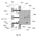
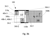
図3a、図3b、及び、図3cには、線形案内アセンブリ100における複数の磁気軸受アセンブリの実装又は適用の一例(それぞれ上面図、正面図、及び、詳細図)が示される。この非限定的な例では、剛体110,300と相互作用している全部で5つの磁気軸受アセンブリ30-1;30-2;30-3;30-4+50-4;30-5+50-5が示される。剛体300は基板/製品キャリアとして規定され、一方、剛体110は、単一の線形ガイドウェイとして規定され、それに沿って基板/製品キャリア300が移動するための固定世界として機能する。
Figures 3a, 3b, and 3c show an example of the implementation or application of multiple magnetic bearing assemblies in a linear guide assembly 100 (top view, front view, and detailed view, respectively). In this non-limiting example, a total of five magnetic bearing assemblies 30-1; 30-2; 30-3; 30-4+50-4; 30-5+50-5 are shown interacting with
本明細書中に記載される磁気軸受アセンブリ30-1;30-2;30-3;30-4+50-4;30-5+50-5は、線形変位経路(x)に沿う単一の線形ガイドウェイ110に対する製品キャリア300)の非接触線形変位を可能にする。キャリア300は、好ましくは、線形変位経路(x)に沿うその輸送中に半導体製品を支持するための平坦、正方形、又は、長方形の支持要素として構成される。キャリア300は、第1の長手方向側300a、第1の長手方向側300aとは反対の第2の長手方向側300b、いずれも単一の線形ガイドウェイ110に沿う輸送方向又は線形変位経路(x)で見て前方側300c及び後方側300d(前方側300cの反対側)を有する。
The magnetic bearing assemblies 30-1; 30-2; 30-3; 30-4+50-4; 30-5+50-5 described herein allow for non-contact linear displacement of a
線形ガイドウェイアセンブリ100は、1つの単一の線形ガイドウェイ又はガイドレール110を備える。このことは、キャリア300が、単一の線形ガイドウェイ又はガイドレール110によって線形変位経路(x)に沿ってその第1の長手方向側300aで支持され、案内され、輸送されるのに対し、他方の第2の反対側の長手方向側300bが支持されずに線形変位経路(x)に沿って自由に移動することを意味する。
The
この非限定的な例では、単一の線形ガイドレール110に第1の案内凹部110aが設けられ、この第1の案内凹部110aは、製品キャリア300から離れる方向を向くガイドレール110の側でガイドレール110の長手方向(x)に延びる。更に、単一の線形ガイドレール110には第2の案内凹部110bが設けられ、この第2の案内凹部110bは、製品キャリア300の方に面するガイドレール110の側でガイドレール110の長手方向(x)に延びる。両方の案内凹部110a-110bは、1つ以上の磁気軸受アセンブリ30-1;30-2;30-3;30-4+50-4;30-5+50-5を部分的に受け入れるのに役立つ。磁気軸受アセンブリ30-1;30-2;30-3;30-4+50-4;30-5+50-5は、幾つかのキャリアサポート300-1;300-2;300-3;300-4;300-5によってキャリア300に取り付けられる。製品キャリア300は、単一の線形ガイドレール110によって形成される線形ガイドウェイ100に取り付けられて線形ガイドウェイ100に沿って案内される。
In this non-limiting example, the single
係属中の特許請求の範囲で規定されるように並びに図2a-図2b及び図3a-図3cの例に関連して明らかにされるように、製品キャリア300が剛体の一方を構成し、ガイドレール110が剛体の他方を構成することに留意されたい。
It should be noted that the
特に、線形ガイドウェイアセンブリ100のこの例において、幾つかの磁気軸受アセンブリ30-1;30-2;30-3;30-4+50-4;30-5+50-5は、高清浄度基板処理環境における基板キャリア処理ロボットの一部として、変位ストロークが例えば600mmの直線ガイドウェイに実装される。単一の直線又は線形ガイドウェイ110は、作動のために利用可能な1つの並進自由度(x)を可能にし、これにより、単一の線形ガイドウェイ110によって規定される線形変位経路に沿ってx方向にキャリア300を変位させることができる。
In particular, in this example of a
図3a-3b-3cに概略的に示されるように、残りの5つの自由度y、z、θ、Ф、ψが制約される。磁気軸受アセンブリ30-1;30-2;30-3;30-4+50-4;30-5+50-5は、製品キャリア300に接続され又は取り付けられるとともに、ロボットの進行リンク又はアームの一部である変位ビーム(図示せず)に対して5つの自由度y、z、θ、Ф、ψを制約する。この例では、5つの磁気軸受アセンブリ30-1;30-2;30-3;30-4+50-4;30-5+50-5が適用される。
The remaining five degrees of freedom y, z, θ, Φ, ψ are constrained as shown diagrammatically in Figures 3a-3b-3c. Magnetic bearing assemblies 30-1; 30-2; 30-3; 30-4+50-4; 30-5+50-5 are connected or attached to the
この例で実装される磁気軸受モジュールは、可変リラクタンス原理に基づくとともに、電磁アクチュエータ、位置測定、及び、随意的に予荷重のための永久磁石から成り、後者は、一定の反力を生み出すべく又は製品キャリアの重量とその負荷によって生み出される重力を相殺することによって電力損失を最小限に抑えるべく静的で一定の力を与えるために使用されることを特徴とする。これらの軸受モジュールのそれぞれは、引力のみ(したがって、一方向の力のみ)を生成できる。両方向の作動を可能にするには、引力に対して反対方向の予荷重が必要とされる。 The magnetic bearing modules implemented in this example are characterized by being based on the variable reluctance principle and consisting of an electromagnetic actuator, a permanent magnet for position measurement and, optionally, a preload, the latter being used to provide a static, constant force to generate a constant reaction force or to minimize power losses by counteracting the gravitational force generated by the weight of the product carrier and its load. Each of these bearing modules can generate only an attractive force (and therefore only a force in one direction). To allow operation in both directions, a preload in the opposite direction to the attractive force is required.
3つの磁気軸受アセンブリ30-1;30-2;30-3は、単一の線形ガイドウェイ又はガイドレール110に対するキャリア300の面外自由度、すなわち、z方向、Ф方向、ψ方向を制約する。2つの更なる磁気軸受アセンブリ30-4+50-4;30-5+50-5は、残りの面内自由度y、θを課す。
The three magnetic bearing assemblies 30-1; 30-2; 30-3 constrain the out-of-plane degrees of freedom of the
3つの面外磁気アセンブリ30-1;30-2;30-3に関して前述した任意の予荷重印加は、重力によって実行(バイアス)され、したがって、図2a-図2bに示されるような更なる設定モジュール50を実装せず、この設定モジュールはプレストレス軸受として機能する。これは、この実施形態の明らかな利点である。
The optional preload application described above for the three out-of-plane magnetic assemblies 30-1; 30-2; 30-3 is performed (biased) by gravity, and therefore does not implement an
3つの面外磁気軸受アセンブリ30-1、30-2、30-3の調整又は予荷重印加は、それぞれの磁気軸受アセンブリごとに空隙40b-1;40b-2;40b-3を調整し、それにより、アセンブリの静的な力を重力と一致させて、定常状態散逸を最小限に抑えることによって各磁気軸受アセンブリ30-1;30-2;30-3のEコア31及びコイル35により形成される電磁石によって実行される(図2a-図2b参照)。
Tuning or preloading the three out-of-plane magnetic bearing assemblies 30-1, 30-2, 30-3 is performed by the electromagnets formed by the E-cores 31 and coils 35 of each magnetic bearing assembly 30-1; 30-2; 30-3 by tuning the
同様に、各磁気アセンブリ30-1;30-2;30-3のEコア31及びコイル35によって形成される電磁石は、それらのそれぞれの第1の永久磁石34-1;34-2;34-3と共に、製品キャリア300と単一の線形ガイドレール110との間の空隙距離g1(40b-1;40b-2;40b-3)を事前設定して制御する。
Similarly, the electromagnets formed by the E-cores 31 and coils 35 of each magnetic assembly 30-1; 30-2; 30-3, together with their respective first permanent magnets 34-1; 34-2; 34-3, preset and control the gap distance g1 (40b-1; 40b-2; 40b-3) between the
磁気アセンブリ30-1;30-2;30-3の予荷重印加は、制御ループによって補償される必要がある更なる負の剛性を犠牲にして、メカニズムの重量によってではなく、永久磁石34-1;34-2;34-3を使用して行なわれ得る。 The preloading of the magnetic assemblies 30-1; 30-2; 30-3 can be done using permanent magnets 34-1; 34-2; 34-3 rather than by the weight of the mechanism, at the expense of additional negative stiffness that needs to be compensated for by the control loop.
磁気軸受モジュール30-1,30-2は、面外自由度z,ψを制約し、単一の線形案内レール110の第2の案内凹部110bに受け入れられる。これらの磁気軸受モジュールには、キャリッジの重力とペイロード質量とによって予荷重が付与される。したがって、これらの2つの磁気軸受モジュール30-1,30-2は、基板/製品キャリア300及びそれに取り付けられるそのペイロード(例えば、半導体基板)の重量を補償する静的な力を生成するべく永久磁石34(図2a-図2b参照)を含む。これらの軸受の空隙は、静的永久磁石34の力と重量を運ぶのに必要な一定の力とのバランスを取り、それにより、電力損失を最小限に抑えるべく、機械的に調整され得る。磁気軸受モジュール30-1,30-2は、永久磁石の公差及び機械的公差を補償し得る。制御ループを閉じるために、変位センサが、それぞれの個々の軸受モジュールごとに1つずつ使用される。
The magnetic bearing modules 30-1, 30-2 constrain the out-of-plane degrees of freedom z, ψ and are received in the
磁気軸受モジュール30-3は、回転自由度Фを制約し、それにより、キャリアによって規定されるその平面内での基板/製品キャリア300の望ましくない回転を防止する。磁気軸受モジュール30-3は、単一の線形案内レール110の第1の案内凹部110aに受け入れられ、散逸を最小化するために静的な力のバランスを取るべく重力によって予荷重が付与される永久磁石34を含む。変位センサが制御ループを閉じるために使用される。
The magnetic bearing module 30-3 constrains the rotational degree of freedom Φ, thereby preventing undesired rotation of the substrate/
面内自由度y,θは、2つの磁気アセンブリ30-4+50-4及び30-5+50-5によって予荷重が付与される。位置制御ループは変位センサ(容量性、光学式、その他)を使用して閉じられる。個々の設定モジュール50-4、50-5はそれぞれ、1つの変位センサを必要とするが、これらの軸受に作用する静的な力が何もないため、第2の永久磁石51を実装しない。或いは、設定モジュール50-4、50-5の予荷重印加は、永久磁石51を使用して行なわれ得るが、これは、制御ループによって補償される必要がある更なる負の剛性をもたらす。
The in-plane degrees of freedom y and θ are preloaded by two magnetic assemblies 30-4+50-4 and 30-5+50-5. The position control loop is closed using a displacement sensor (capacitive, optical, etc.). Each individual setting module 50-4, 50-5 requires one displacement sensor but does not implement a second
設定モジュール50-4、50-5は、単一の線形ガイドウェイ/ガイドレール110の第1の案内凹部110aに受け入れられ、y及びθ軸受モジュール30-4、30-5に予荷重力を与える。静的な状態では、軸受モジュール30-4+30-5及び設定モジュール50-4+50-5の両方が、磁気ヒステリシスを回避するために数ニュートンの小さな(反対の)引力を生成する。予荷重軸受は位置センサを何ら必要としない。他の予荷重機構が、一定の力を生成するべく永久磁石51のみから成ることができるが、この場合、互いに対して作用する2つの永久磁石に固有の負の剛性が回避される。予荷重軸受の空隙は、機械的公差を補償するために機械的に調整され得る。
The setting modules 50-4, 50-5 are received in the
ここで、設定モジュール50-4、50-5並びに磁気軸受モジュール30-4、30-5(それぞれは、Eコア31、コイル35、及び、第1の永久磁石34-4、34-5のそれぞれから構成される)は、基板/製品キャリア300と単一の線形ガイドレール110との間の所望の空隙20a-4、20a-5を制御又は維持する製品キャリア300の同じ側に取り付けられる。
Here, the setting modules 50-4, 50-5 and the magnetic bearing modules 30-4, 30-5 (each consisting of an E-core 31, a
5つの自由度が制約される従来の転がり線形軸受とは対照的に、5つの制約された自由度は、能動的な制御可能な磁気軸受アセンブリ30-1;30-2;30-3;30-4+50-4;30-5+50-5を使用して能動的に制御することができ、それにより、線形ガイドウェイアセンブリ100のガイドレール110に沿って基板/製品キャリア300を変位させているロボットの望ましくない動的挙動を補正することができる。
In contrast to conventional rolling linear bearings where five degrees of freedom are constrained, the five constrained degrees of freedom can be actively controlled using active controllable magnetic bearing assemblies 30-1; 30-2; 30-3; 30-4+50-4; 30-5+50-5, thereby compensating for undesirable dynamic behavior of the robot displacing the substrate/
係属中の請求項で規定される磁気軸受アセンブリの先の例は、高清浄度基板処理ロボット用途における商業規模での実施に非常に適している。特に、製品キャリアがその一方の単一の長手方向側で1つの単一の線形ガイドウェイによって支持され、案内され、及び、輸送されるとともに、製品キャリアの他方の反対の長手方向側並びにその前方側及び後方側が支持されずに1つの単一の線形ガイドウェイによって規定される線形変位経路(x)に沿って自由に移動していることにより、製品キャリア周辺の作業場所のアクセス可能性及び可視性が大幅に向上する。 The above example of a magnetic bearing assembly as defined in the pending claims is highly suitable for commercial scale implementation in high cleanliness substrate processing robotic applications. In particular, the product carrier is supported, guided and transported on one single longitudinal side thereof by one single linear guideway, while the other opposite longitudinal side of the product carrier as well as its front and rear sides are unsupported and free to move along a linear displacement path (x) defined by one single linear guideway, thereby significantly improving the accessibility and visibility of the work area around the product carrier.
特に、一方の長手方向側が支持され、案内され、輸送されるとともに、反対側が支持されずに自由に移動する側であるそのような製品キャリアは、ロボットピックアンドプレースアームなどのロボット用途のためのアクセス性の向上を示す。 In particular, such product carriers, in which one longitudinal side is supported, guided and transported and the opposite side is unsupported and free to move, offer improved accessibility for robotic applications, such as robotic pick-and-place arms.
本発明の磁気軸受アセンブリは、限られた寸法により低コストで構築できるとともに、1つの剛体(基板キャリア300)の他の剛体(ガイドウェイアセンブリ100-110)に対する安定したうまく制御される線形変位が品質保証目的のために不可欠である基板ウェーハ処理用途などの熱的に重要なシステム及び真空環境で容易に実装できる。 The magnetic bearing assembly of the present invention can be constructed at low cost due to its limited dimensions and can be easily implemented in thermally critical systems and vacuum environments such as substrate wafer processing applications where stable and well-controlled linear displacement of one rigid body (the substrate carrier 300) relative to another rigid body (the guideway assemblies 100-110) is essential for quality assurance purposes.
特に、提案された磁気軸受アセンブリは、一般に知られている転がり軸受では不可能なそのような熱的に重要なシステム及び真空環境において変位安定性、剛性、及び、エネルギー散逸を可能にする。 In particular, the proposed magnetic bearing assembly enables displacement stability, stiffness, and energy dissipation in such thermally critical systems and vacuum environments that are not possible with commonly known rolling bearings.
Claims (16)
前記線形変位経路を規定する前記他の剛体である単一の線形ガイドウェイとして形成される1つの単一の剛体、並びに、
前記単一の線形ガイドウェイに沿って変位可能な製品キャリアとして形成される少なくとも1つの可動剛体、
を備え、
前記線形ガイドウェイアセンブリは、前記単一の線形ガイドウェイに対する前記少なくとも1つの製品キャリアの非接触線形変位を可能にするための複数の磁気軸受アセンブリのグループを更に備え、
前記磁気軸受アセンブリのグループは、前記磁気軸受アセンブリのグループが単一の線形ガイドウェイに対する前記製品キャリアの5つの自由度(y、z、θ、Ф、ψ)を制約して配置される一方で単一の線形ガイドウェイに沿う前記製品キャリアの1つの並進自由度(x)を許容するように前記製品キャリアに取り付けられ、
前記製品キャリアは、少なくとも、前記線形変位経路(x)の方向を向く、前記単一の線形ガイドウェイに最も近い唯一の第1の長手方向側と、前記第1の長手方向側とは反対の第2の長手方向側を含み、
前記製品キャリアは、単一の線形ガイドウェイによって前記線形変位経路(x)に沿ってその第1の長手方向側で支持され、案内され、輸送され、一方、他方の反対の第2の長手方向側は、支持されずに、前記線形変位経路(x)に沿って自由に移動し、前記磁気軸受アセンブリのグループは、前記製品キャリアの前記第1の長手方向側のみに取り付けられる、
線形ガイドウェイアセンブリ。 1. A linear guideway assembly for non-contact linear displacement of a moveable rigid body relative to another rigid body along a linear displacement path (x), comprising:
a single rigid body formed as a single linear guideway, the other rigid body defining the linear displacement path; and
at least one movable rigid body formed as a product carrier displaceable along said single linear guideway;
Equipped with
the linear guideway assembly further comprising a group of a plurality of magnetic bearing assemblies for enabling non-contact linear displacement of the at least one product carrier relative to the single linear guideway;
the group of magnetic bearing assemblies is attached to the product carrier such that the group of magnetic bearing assemblies is positioned constraining five degrees of freedom (y, z, θ, Φ, ψ) of the product carrier relative to a single linear guideway while allowing one translational degree of freedom (x) of the product carrier along the single linear guideway;
the product carrier includes at least a unique first longitudinal side that faces in a direction of the linear displacement path (x) and is closest to the single linear guideway, and a second longitudinal side that is opposite the first longitudinal side ;
the product carrier is supported, guided and transported at a first longitudinal side thereof along the linear displacement path (x) by a single linear guideway, while an opposite second longitudinal side is unsupported and free to move along the linear displacement path (x), and the group of magnetic bearing assemblies is attached only to the first longitudinal side of the product carrier;
Linear guideway assembly.
-前記製品キャリアに取り付けられるとともに、
強磁性コアと、
前記強磁性コアの第1の側に位置されて前記単一の線形ガイドウェイに向けて方向付けられる第1の磁気要素と、
前記強磁性コアの周囲に巻回されるコイルと、
から少なくとも成る、少なくとも1つの磁気軸受モジュール、
を少なくとも備え、
前記1つの軸受モジュールが、使用中に、前記単一の線形ガイドウェイとの隙間距離を維持して配置される、
請求項2から5のいずれか一項に記載の線形ガイドウェイアセンブリ。 Each of the magnetic bearing assemblies comprises:
- attached to said product carrier;
A ferromagnetic core;
a first magnetic element located on a first side of the ferromagnetic core and oriented toward the single linear guideway;
A coil wound around the ferromagnetic core;
At least one magnetic bearing module,
At least
the one bearing module is positioned to maintain a clearance distance with the single linear guideway during use;
A linear guideway assembly according to any one of claims 2 to 5.
Applications Claiming Priority (3)
| Application Number | Priority Date | Filing Date | Title |
|---|---|---|---|
| NL2022986A NL2022986B1 (en) | 2019-04-19 | 2019-04-19 | A linear guideway assembly for contactless linear displacement of a rigid body relative to another rigid body along a linear displacement path. |
| NL2022986 | 2019-04-19 | ||
| PCT/NL2020/050123 WO2020214025A1 (en) | 2019-04-19 | 2020-02-26 | A linear guideway assembly for contactless linear displacement of a rigid body relative to another rigid body along a linear displacement path |
Publications (2)
| Publication Number | Publication Date |
|---|---|
| JP2022529790A JP2022529790A (en) | 2022-06-24 |
| JP7635147B2 true JP7635147B2 (en) | 2025-02-25 |
Family
ID=66776839
Family Applications (1)
| Application Number | Title | Priority Date | Filing Date |
|---|---|---|---|
| JP2021562172A Active JP7635147B2 (en) | 2019-04-19 | 2020-02-26 | Linear guideway assembly for non-contact linear displacement of a rigid body relative to another rigid body along a linear displacement path - Patents.com |
Country Status (7)
| Country | Link |
|---|---|
| US (1) | US11867229B2 (en) |
| EP (1) | EP3956576B1 (en) |
| JP (1) | JP7635147B2 (en) |
| KR (1) | KR102807430B1 (en) |
| NL (1) | NL2022986B1 (en) |
| TW (1) | TWI856087B (en) |
| WO (1) | WO2020214025A1 (en) |
Families Citing this family (2)
| Publication number | Priority date | Publication date | Assignee | Title |
|---|---|---|---|---|
| NL2027543B1 (en) * | 2021-02-11 | 2022-09-12 | Vdl Enabling Tech Group B V | A capacitive sensor device and a magnetic bearing assembly with such capacitive sensor device. |
| KR102749176B1 (en) | 2022-04-08 | 2024-12-31 | 하이윈 테크놀로지스 코포레이션 | Method for inspecting deviation in dynamic characteristics of a feeding system |
Citations (2)
| Publication number | Priority date | Publication date | Assignee | Title |
|---|---|---|---|---|
| JP2002120120A (en) | 2000-10-17 | 2002-04-23 | Matsushita Electric Ind Co Ltd | Method for correcting table moving state of magnetic bearing linear stage, magnetic bearing linear stage and processing machine using the same |
| US20150211575A1 (en) | 2014-01-28 | 2015-07-30 | Samsung Electronics Co., Ltd. | Driving device and bearing including the same |
Family Cites Families (8)
| Publication number | Priority date | Publication date | Assignee | Title |
|---|---|---|---|---|
| JPS602068A (en) * | 1983-06-17 | 1985-01-08 | Nippon Telegr & Teleph Corp <Ntt> | Magnetically levitating straight line travel guide |
| JPH0788850B2 (en) * | 1986-01-14 | 1995-09-27 | 光洋精工株式会社 | Magnetic levitation slide |
| US5196745A (en) * | 1991-08-16 | 1993-03-23 | Massachusetts Institute Of Technology | Magnetic positioning device |
| US5814774A (en) * | 1996-03-29 | 1998-09-29 | Otis Elevator Company | Elevator system having a force-estimation or position-scheduled current command controller |
| KR101318211B1 (en) * | 2011-05-31 | 2013-10-15 | 한국기계연구원 | Active compensated stage having 5-dof motion error compensation and motion error compensating method thereof |
| CN103277409B (en) * | 2013-01-14 | 2017-02-01 | 哈尔滨工业大学 | Five-freedom degree magnetic levitation guide rail with electromagnet distribution |
| NL2019812B1 (en) * | 2017-10-26 | 2019-05-06 | Vdl Enabling Tech Group B V | A magnetic bearing assembly as well as a linear guideway assembly implementing one or more such magnetic bearing assemblies. |
| JP7147913B1 (en) * | 2021-04-19 | 2022-10-05 | 井関農機株式会社 | root crop harvester |
-
2019
- 2019-04-19 NL NL2022986A patent/NL2022986B1/en active
-
2020
- 2020-02-26 KR KR1020217037764A patent/KR102807430B1/en active Active
- 2020-02-26 EP EP20707855.1A patent/EP3956576B1/en active Active
- 2020-02-26 JP JP2021562172A patent/JP7635147B2/en active Active
- 2020-02-26 US US17/604,704 patent/US11867229B2/en active Active
- 2020-02-26 WO PCT/NL2020/050123 patent/WO2020214025A1/en not_active Ceased
- 2020-04-08 TW TW109111791A patent/TWI856087B/en active
Patent Citations (2)
| Publication number | Priority date | Publication date | Assignee | Title |
|---|---|---|---|---|
| JP2002120120A (en) | 2000-10-17 | 2002-04-23 | Matsushita Electric Ind Co Ltd | Method for correcting table moving state of magnetic bearing linear stage, magnetic bearing linear stage and processing machine using the same |
| US20150211575A1 (en) | 2014-01-28 | 2015-07-30 | Samsung Electronics Co., Ltd. | Driving device and bearing including the same |
Also Published As
| Publication number | Publication date |
|---|---|
| KR102807430B1 (en) | 2025-05-13 |
| NL2022986B1 (en) | 2020-10-27 |
| KR20220029550A (en) | 2022-03-08 |
| WO2020214025A1 (en) | 2020-10-22 |
| JP2022529790A (en) | 2022-06-24 |
| US11867229B2 (en) | 2024-01-09 |
| TWI856087B (en) | 2024-09-21 |
| EP3956576B1 (en) | 2023-08-09 |
| EP3956576A1 (en) | 2022-02-23 |
| TW202106992A (en) | 2021-02-16 |
| US20220205483A1 (en) | 2022-06-30 |
Similar Documents
| Publication | Publication Date | Title |
|---|---|---|
| JP7387615B2 (en) | a magnetic bearing assembly and a linear guideway assembly implementing one or more such magnetic bearing assemblies | |
| KR100445848B1 (en) | A stage and a method of operating the stage | |
| JP5575802B2 (en) | Integrated stage positioning system and method | |
| JP7635147B2 (en) | Linear guideway assembly for non-contact linear displacement of a rigid body relative to another rigid body along a linear displacement path - Patents.com | |
| KR20220002515A (en) | Magnetic levitation system, base and carrier of magnetic levitation system, and method of levitating carrier | |
| KR20020009616A (en) | Hybrid magnetically supported carriage transporter | |
| US11393706B2 (en) | Magnetically-levitated transporter | |
| US20240258063A1 (en) | Stage Device, Charged Particle Beam Device, and Vacuum Device | |
| US20230400057A1 (en) | Levitating transport system | |
| US6515381B1 (en) | Cantilever stage | |
| JP2005310808A (en) | Electron beam exposure equipment | |
| US12021432B2 (en) | Actuator device for use in a positioning system as well as such positioning system | |
| JP2025176268A (en) | Stage device, charged particle beam device and vacuum device | |
| WO2025134501A1 (en) | Driving apparatus, positioning apparatus, processing apparatus, and device manufacturing method | |
| Puci | Magnetically levitated and guided systems | |
| WO2025134500A1 (en) | Driving device, positioning device, processing device, and device manufacturing method | |
| JP2023035181A (en) | Transportation device, processing system, control method, and method for producing article | |
| JP2025186849A (en) | Substrate transport device, substrate transport system, and substrate transport method | |
| JPH10281110A (en) | Non-contact rodless cylinder and stage device using the same | |
| Yusuke et al. | 2 DOF Maglev System with Permanent Magnet Motion Control |
Legal Events
| Date | Code | Title | Description |
|---|---|---|---|
| A621 | Written request for application examination |
Free format text: JAPANESE INTERMEDIATE CODE: A621 Effective date: 20221115 |
|
| A977 | Report on retrieval |
Free format text: JAPANESE INTERMEDIATE CODE: A971007 Effective date: 20231130 |
|
| A131 | Notification of reasons for refusal |
Free format text: JAPANESE INTERMEDIATE CODE: A131 Effective date: 20231205 |
|
| A521 | Request for written amendment filed |
Free format text: JAPANESE INTERMEDIATE CODE: A523 Effective date: 20240228 |
|
| A131 | Notification of reasons for refusal |
Free format text: JAPANESE INTERMEDIATE CODE: A131 Effective date: 20240319 |
|
| A521 | Request for written amendment filed |
Free format text: JAPANESE INTERMEDIATE CODE: A523 Effective date: 20240418 |
|
| A131 | Notification of reasons for refusal |
Free format text: JAPANESE INTERMEDIATE CODE: A131 Effective date: 20240709 |
|
| A521 | Request for written amendment filed |
Free format text: JAPANESE INTERMEDIATE CODE: A523 Effective date: 20241009 |
|
| TRDD | Decision of grant or rejection written | ||
| A01 | Written decision to grant a patent or to grant a registration (utility model) |
Free format text: JAPANESE INTERMEDIATE CODE: A01 Effective date: 20250114 |
|
| A61 | First payment of annual fees (during grant procedure) |
Free format text: JAPANESE INTERMEDIATE CODE: A61 Effective date: 20250212 |
|
| R150 | Certificate of patent or registration of utility model |
Ref document number: 7635147 Country of ref document: JP Free format text: JAPANESE INTERMEDIATE CODE: R150 |