JP7630833B2 - Ferrite powder, ferrite resin composite material, electromagnetic shielding material, electronic material or electronic parts - Google Patents
Ferrite powder, ferrite resin composite material, electromagnetic shielding material, electronic material or electronic parts Download PDFInfo
- Publication number
- JP7630833B2 JP7630833B2 JP2021551690A JP2021551690A JP7630833B2 JP 7630833 B2 JP7630833 B2 JP 7630833B2 JP 2021551690 A JP2021551690 A JP 2021551690A JP 2021551690 A JP2021551690 A JP 2021551690A JP 7630833 B2 JP7630833 B2 JP 7630833B2
- Authority
- JP
- Japan
- Prior art keywords
- ferrite
- particles
- ferrite powder
- powder
- step structure
- Prior art date
- Legal status (The legal status is an assumption and is not a legal conclusion. Google has not performed a legal analysis and makes no representation as to the accuracy of the status listed.)
- Active
Links
Images
Classifications
-
- C—CHEMISTRY; METALLURGY
- C01—INORGANIC CHEMISTRY
- C01G—COMPOUNDS CONTAINING METALS NOT COVERED BY SUBCLASSES C01D OR C01F
- C01G49/00—Compounds of iron
- C01G49/02—Oxides; Hydroxides
- C01G49/06—Ferric oxide [Fe2O3]
-
- H—ELECTRICITY
- H01—ELECTRIC ELEMENTS
- H01F—MAGNETS; INDUCTANCES; TRANSFORMERS; SELECTION OF MATERIALS FOR THEIR MAGNETIC PROPERTIES
- H01F1/00—Magnets or magnetic bodies characterised by the magnetic materials therefor; Selection of materials for their magnetic properties
- H01F1/01—Magnets or magnetic bodies characterised by the magnetic materials therefor; Selection of materials for their magnetic properties of inorganic materials
- H01F1/03—Magnets or magnetic bodies characterised by the magnetic materials therefor; Selection of materials for their magnetic properties of inorganic materials characterised by their coercivity
- H01F1/12—Magnets or magnetic bodies characterised by the magnetic materials therefor; Selection of materials for their magnetic properties of inorganic materials characterised by their coercivity of soft-magnetic materials
- H01F1/34—Magnets or magnetic bodies characterised by the magnetic materials therefor; Selection of materials for their magnetic properties of inorganic materials characterised by their coercivity of soft-magnetic materials non-metallic substances, e.g. ferrites
- H01F1/36—Magnets or magnetic bodies characterised by the magnetic materials therefor; Selection of materials for their magnetic properties of inorganic materials characterised by their coercivity of soft-magnetic materials non-metallic substances, e.g. ferrites in the form of particles
- H01F1/37—Magnets or magnetic bodies characterised by the magnetic materials therefor; Selection of materials for their magnetic properties of inorganic materials characterised by their coercivity of soft-magnetic materials non-metallic substances, e.g. ferrites in the form of particles in a bonding agent
-
- C—CHEMISTRY; METALLURGY
- C01—INORGANIC CHEMISTRY
- C01G—COMPOUNDS CONTAINING METALS NOT COVERED BY SUBCLASSES C01D OR C01F
- C01G49/00—Compounds of iron
- C01G49/0018—Mixed oxides or hydroxides
- C01G49/0072—Mixed oxides or hydroxides containing manganese
-
- C—CHEMISTRY; METALLURGY
- C08—ORGANIC MACROMOLECULAR COMPOUNDS; THEIR PREPARATION OR CHEMICAL WORKING-UP; COMPOSITIONS BASED THEREON
- C08K—Use of inorganic or non-macromolecular organic substances as compounding ingredients
- C08K3/00—Use of inorganic substances as compounding ingredients
- C08K3/18—Oxygen-containing compounds, e.g. metal carbonyls
- C08K3/20—Oxides; Hydroxides
- C08K3/22—Oxides; Hydroxides of metals
-
- C—CHEMISTRY; METALLURGY
- C08—ORGANIC MACROMOLECULAR COMPOUNDS; THEIR PREPARATION OR CHEMICAL WORKING-UP; COMPOSITIONS BASED THEREON
- C08L—COMPOSITIONS OF MACROMOLECULAR COMPOUNDS
- C08L101/00—Compositions of unspecified macromolecular compounds
-
- C—CHEMISTRY; METALLURGY
- C08—ORGANIC MACROMOLECULAR COMPOUNDS; THEIR PREPARATION OR CHEMICAL WORKING-UP; COMPOSITIONS BASED THEREON
- C08L—COMPOSITIONS OF MACROMOLECULAR COMPOUNDS
- C08L63/00—Compositions of epoxy resins; Compositions of derivatives of epoxy resins
-
- H—ELECTRICITY
- H01—ELECTRIC ELEMENTS
- H01F—MAGNETS; INDUCTANCES; TRANSFORMERS; SELECTION OF MATERIALS FOR THEIR MAGNETIC PROPERTIES
- H01F1/00—Magnets or magnetic bodies characterised by the magnetic materials therefor; Selection of materials for their magnetic properties
- H01F1/01—Magnets or magnetic bodies characterised by the magnetic materials therefor; Selection of materials for their magnetic properties of inorganic materials
- H01F1/03—Magnets or magnetic bodies characterised by the magnetic materials therefor; Selection of materials for their magnetic properties of inorganic materials characterised by their coercivity
- H01F1/12—Magnets or magnetic bodies characterised by the magnetic materials therefor; Selection of materials for their magnetic properties of inorganic materials characterised by their coercivity of soft-magnetic materials
- H01F1/34—Magnets or magnetic bodies characterised by the magnetic materials therefor; Selection of materials for their magnetic properties of inorganic materials characterised by their coercivity of soft-magnetic materials non-metallic substances, e.g. ferrites
-
- H—ELECTRICITY
- H05—ELECTRIC TECHNIQUES NOT OTHERWISE PROVIDED FOR
- H05K—PRINTED CIRCUITS; CASINGS OR CONSTRUCTIONAL DETAILS OF ELECTRIC APPARATUS; MANUFACTURE OF ASSEMBLAGES OF ELECTRICAL COMPONENTS
- H05K9/00—Screening of apparatus or components against electric or magnetic fields
- H05K9/0073—Shielding materials
- H05K9/0075—Magnetic shielding materials
-
- H—ELECTRICITY
- H05—ELECTRIC TECHNIQUES NOT OTHERWISE PROVIDED FOR
- H05K—PRINTED CIRCUITS; CASINGS OR CONSTRUCTIONAL DETAILS OF ELECTRIC APPARATUS; MANUFACTURE OF ASSEMBLAGES OF ELECTRICAL COMPONENTS
- H05K9/00—Screening of apparatus or components against electric or magnetic fields
- H05K9/0073—Shielding materials
- H05K9/0081—Electromagnetic shielding materials, e.g. EMI, RFI shielding
- H05K9/0083—Electromagnetic shielding materials, e.g. EMI, RFI shielding comprising electro-conductive non-fibrous particles embedded in an electrically insulating supporting structure, e.g. powder, flakes, whiskers
-
- C—CHEMISTRY; METALLURGY
- C01—INORGANIC CHEMISTRY
- C01P—INDEXING SCHEME RELATING TO STRUCTURAL AND PHYSICAL ASPECTS OF SOLID INORGANIC COMPOUNDS
- C01P2004/00—Particle morphology
- C01P2004/01—Particle morphology depicted by an image
- C01P2004/03—Particle morphology depicted by an image obtained by SEM
-
- C—CHEMISTRY; METALLURGY
- C01—INORGANIC CHEMISTRY
- C01P—INDEXING SCHEME RELATING TO STRUCTURAL AND PHYSICAL ASPECTS OF SOLID INORGANIC COMPOUNDS
- C01P2004/00—Particle morphology
- C01P2004/30—Particle morphology extending in three dimensions
-
- C—CHEMISTRY; METALLURGY
- C01—INORGANIC CHEMISTRY
- C01P—INDEXING SCHEME RELATING TO STRUCTURAL AND PHYSICAL ASPECTS OF SOLID INORGANIC COMPOUNDS
- C01P2004/00—Particle morphology
- C01P2004/30—Particle morphology extending in three dimensions
- C01P2004/32—Spheres
-
- C—CHEMISTRY; METALLURGY
- C01—INORGANIC CHEMISTRY
- C01P—INDEXING SCHEME RELATING TO STRUCTURAL AND PHYSICAL ASPECTS OF SOLID INORGANIC COMPOUNDS
- C01P2004/00—Particle morphology
- C01P2004/51—Particles with a specific particle size distribution
-
- C—CHEMISTRY; METALLURGY
- C01—INORGANIC CHEMISTRY
- C01P—INDEXING SCHEME RELATING TO STRUCTURAL AND PHYSICAL ASPECTS OF SOLID INORGANIC COMPOUNDS
- C01P2004/00—Particle morphology
- C01P2004/60—Particles characterised by their size
- C01P2004/61—Micrometer sized, i.e. from 1-100 micrometer
-
- C—CHEMISTRY; METALLURGY
- C01—INORGANIC CHEMISTRY
- C01P—INDEXING SCHEME RELATING TO STRUCTURAL AND PHYSICAL ASPECTS OF SOLID INORGANIC COMPOUNDS
- C01P2004/00—Particle morphology
- C01P2004/60—Particles characterised by their size
- C01P2004/62—Submicrometer sized, i.e. from 0.1-1 micrometer
-
- C—CHEMISTRY; METALLURGY
- C01—INORGANIC CHEMISTRY
- C01P—INDEXING SCHEME RELATING TO STRUCTURAL AND PHYSICAL ASPECTS OF SOLID INORGANIC COMPOUNDS
- C01P2006/00—Physical properties of inorganic compounds
- C01P2006/10—Solid density
-
- C—CHEMISTRY; METALLURGY
- C01—INORGANIC CHEMISTRY
- C01P—INDEXING SCHEME RELATING TO STRUCTURAL AND PHYSICAL ASPECTS OF SOLID INORGANIC COMPOUNDS
- C01P2006/00—Physical properties of inorganic compounds
- C01P2006/12—Surface area
-
- C—CHEMISTRY; METALLURGY
- C01—INORGANIC CHEMISTRY
- C01P—INDEXING SCHEME RELATING TO STRUCTURAL AND PHYSICAL ASPECTS OF SOLID INORGANIC COMPOUNDS
- C01P2006/00—Physical properties of inorganic compounds
- C01P2006/42—Magnetic properties
-
- C—CHEMISTRY; METALLURGY
- C08—ORGANIC MACROMOLECULAR COMPOUNDS; THEIR PREPARATION OR CHEMICAL WORKING-UP; COMPOSITIONS BASED THEREON
- C08K—Use of inorganic or non-macromolecular organic substances as compounding ingredients
- C08K3/00—Use of inorganic substances as compounding ingredients
- C08K3/18—Oxygen-containing compounds, e.g. metal carbonyls
- C08K3/20—Oxides; Hydroxides
- C08K3/22—Oxides; Hydroxides of metals
- C08K2003/2262—Oxides; Hydroxides of metals of manganese
-
- C—CHEMISTRY; METALLURGY
- C08—ORGANIC MACROMOLECULAR COMPOUNDS; THEIR PREPARATION OR CHEMICAL WORKING-UP; COMPOSITIONS BASED THEREON
- C08K—Use of inorganic or non-macromolecular organic substances as compounding ingredients
- C08K3/00—Use of inorganic substances as compounding ingredients
- C08K3/18—Oxygen-containing compounds, e.g. metal carbonyls
- C08K3/20—Oxides; Hydroxides
- C08K3/22—Oxides; Hydroxides of metals
- C08K2003/2265—Oxides; Hydroxides of metals of iron
- C08K2003/2272—Ferric oxide (Fe2O3)
-
- C—CHEMISTRY; METALLURGY
- C08—ORGANIC MACROMOLECULAR COMPOUNDS; THEIR PREPARATION OR CHEMICAL WORKING-UP; COMPOSITIONS BASED THEREON
- C08K—Use of inorganic or non-macromolecular organic substances as compounding ingredients
- C08K2201/00—Specific properties of additives
- C08K2201/002—Physical properties
- C08K2201/003—Additives being defined by their diameter
Landscapes
- Chemical & Material Sciences (AREA)
- Organic Chemistry (AREA)
- Medicinal Chemistry (AREA)
- Inorganic Chemistry (AREA)
- Polymers & Plastics (AREA)
- Health & Medical Sciences (AREA)
- Chemical Kinetics & Catalysis (AREA)
- Engineering & Computer Science (AREA)
- Microelectronics & Electronic Packaging (AREA)
- Dispersion Chemistry (AREA)
- Power Engineering (AREA)
- Physics & Mathematics (AREA)
- Electromagnetism (AREA)
- Soft Magnetic Materials (AREA)
- Compounds Of Iron (AREA)
Description
本発明は、フェライト粉末、フェライト樹脂複合材料並びに電磁波シールド材、電子材料又は電子部品に関する。 The present invention relates to ferrite powder, ferrite resin composite materials, and electromagnetic shielding materials, electronic materials, or electronic components.
フェライト粉末と樹脂とからなる複合材料は、電磁波シールド材を始め、様々の用途で多用されている。このような複合材料は、フェライト粉末と樹脂とを混練することで作製される。複合材料はシートなどの形状に成形されて複合体(成形体)となる。このときフェライト粉末を構成する粒子の形状が球形に近いと、成形時の流動性が高くなり、複合体中のフェライト粉末の充填率が高くなる。そのため成形性が良好になるとともに、電磁波遮蔽性能等の特性が良好になる。このような観点から球状又は多面体状の粒子で構成されるフェライト粉末(粒子)が提案されている。Composite materials made of ferrite powder and resin are widely used in a variety of applications, including as electromagnetic shielding materials. Such composite materials are produced by kneading ferrite powder with resin. The composite material is formed into a shape such as a sheet to form a composite body (molded body). In this case, if the shape of the particles that make up the ferrite powder is close to spherical, the fluidity during molding is high and the filling rate of the ferrite powder in the composite body is high. This results in good moldability and good properties such as electromagnetic shielding performance. From this perspective, ferrite powder (particles) made up of spherical or polyhedral particles have been proposed.
例えば、特許文献1(国際公開第2017/212997号)には、平均粒径が1~2000nmの単結晶であり且つ真球状の粒子形状を備えるフェライト粒子であって、当該フェライト粒子は、Znを実質的に含有せず、Mnを3~25重量%、Feを43~65重量%を含有し、当該フェライト粒子とバインダー樹脂とからなる成形体によって測定した複素透磁率の実部が100MHz~1GHzの周波数帯域において極大値を有することを特徴とするフェライト粒子が開示され、該フェライト粒子を電子機器の電磁波シールド材料に用いると、幅広い周波数帯域の電磁波を周波数に関係なく安定して遮蔽できる旨が記載されている(特許文献1の請求項1及び[0078])。For example, Patent Document 1 (WO 2017/212997) discloses ferrite particles that are single crystals having an average particle size of 1 to 2000 nm and a spherical particle shape, the ferrite particles being substantially free of Zn and containing 3 to 25% by weight of Mn and 43 to 65% by weight of Fe, and characterized in that the real part of the complex permeability measured using a molded body made of the ferrite particles and a binder resin has a maximum value in the frequency band of 100 MHz to 1 GHz. It is described that when the ferrite particles are used as an electromagnetic wave shielding material for electronic devices, they can stably shield electromagnetic waves in a wide frequency band regardless of frequency (claim 1 and [0078] of Patent Document 1).
特許文献2(特開2016-60682号公報)には、粒径11μm未満のフェライト粒子を15~30重量%含有し、かつ体積平均粒径が10~50μmであることを特徴とする真球状フェライト粉が開示され、フィラーとして用いられたときの充填性及び成型性が良好で、優れたハンドリング性を有し、かつ高抵抗であることから、この球状フェライト粉を樹脂と共に樹脂組成物とし、さらに成型した成型体は、電磁波吸収用のIC封止剤を始めとする種々の用途に使用可能である旨が記載されている(特許文献2の請求項1及び[0093])。Patent Document 2 (JP 2016-60682 A) discloses a spherical ferrite powder that contains 15 to 30% by weight of ferrite particles with a particle size of less than 11 μm and has a volume average particle size of 10 to 50 μm. It describes that the powder has good filling and moldability when used as a filler, has excellent handleability, and has high resistance, and therefore a molded body obtained by combining this spherical ferrite powder with a resin to form a resin composition can be used for various applications, including an IC sealant for absorbing electromagnetic waves (claims 1 and [0093] of Patent Document 2).
特許文献3(国際公開第2018/061327号)には、平均粒径が1~2000nmの単結晶体であり、且つ、多面体状の粒子形状を備え、Niを5~10重量%含有し、Znを15~30重量%含有し、Cuを1~5重量%含有し、Feを25~50重量%含有することを特徴とするNi-Zn-Cu系フェライト粒子が開示され、該フェライト粒子は、高い飽和磁化と高い電気抵抗を両立して備えることから、磁気フィラーや成形体原料として好適である旨が記載されている(特許文献3の請求項1及び[0089])。Patent Document 3 (WO 2018/061327) discloses Ni-Zn-Cu ferrite particles that are single crystals having an average particle size of 1 to 2000 nm, have a polyhedral particle shape, and contain 5 to 10 wt% Ni, 15 to 30 wt% Zn, 1 to 5 wt% Cu, and 25 to 50 wt% Fe. It is described that the ferrite particles have both high saturation magnetization and high electrical resistance, and are therefore suitable as a magnetic filler or a raw material for compacts (claims 1 and [0089] of Patent Document 3).
特許文献4(特開2006-160560号公報)には、(a)可溶性イオンの含有量が5ppm以下、(b)平均粒子径が10~50μmの範囲であり、(c)X線回折による結晶構造がスピネル構造を示す球状焼結フェライト粒子が開示され、該球状焼結フェライト粒子とシリカ粒子からなる充填材を含有する半導体封止用樹脂組成物は、低粘度で良好な流動特性を有し、しかも電磁波遮蔽機能を有するようになり、この樹脂組成物を封止材料として用いることにより、得られる半導体装置はEMCに優れたものとなる旨が記載されている(特許文献4の請求項1及び[0023])。Patent document 4 (JP Patent Publication No. 2006-160560) discloses spherical sintered ferrite particles having (a) a soluble ion content of 5 ppm or less, (b) an average particle size in the range of 10 to 50 μm, and (c) a crystal structure exhibiting a spinel structure as determined by X-ray diffraction. It describes that a resin composition for semiconductor encapsulation containing a filler consisting of the spherical sintered ferrite particles and silica particles has low viscosity and good flow characteristics, and also has electromagnetic wave shielding properties, and that by using this resin composition as an encapsulating material, the resulting semiconductor device has excellent EMC properties (claims 1 and [0023] of Patent Document 4).
特許文献5(特開平04-304700号公報)には、平均粒径が50~150μmの球状粒子であることを特徴とするMn-Zn系フェライト粒子粉末からなる電波吸収体材料用粉末が開示され、平均粒径を150μm以下の球状とすることにより、従来、材料の大粒径化の支障となっていた射出成形時のゲートの詰まりを流動性の向上により改善できる旨が記載されている(特許文献5の請求項1及び[0008])。Patent document 5 (JP Patent Publication No. 04-304700) discloses a powder for radio wave absorber material consisting of Mn-Zn ferrite particle powder characterized by spherical particles having an average particle size of 50 to 150 μm, and describes that by making the average particle size spherical to 150 μm or less, it is possible to improve the flowability and thereby improve gate clogging during injection molding, which has traditionally been an obstacle to increasing the particle size of the material (claim 1 and [0008] of Patent Document 5).
また電磁波シールド材等の複合材とは異なる用途に用いられるものではあるが、特許文献6(特許第5921801号公報)には、原料としてのFe2O3粉末と、このFe2O3粉末10kg当たり10~50gの副原料としての炭酸塩と、還元剤としての混合物を顆粒化した後、1000℃以下の温度で焼成して、粒子の表面に同心円状に広がった隆起部分の集合であるステップ状の凹凸を有するキャリア芯材を製造することを特徴とする、電子写真現像剤用キャリア芯材の製造方法が開示され、該キャリア芯材は球形度が0.8以上である旨が記載されている(特許文献6の請求項1及び[0024])。 Although it is used for purposes other than composite materials such as electromagnetic wave shielding materials, Patent Document 6 (Japanese Patent No. 5,921,801) discloses a method for producing a carrier core material for electrophotographic developers, which is characterized in that a mixture of Fe2O3 powder as a raw material, 10 to 50 g of carbonate as an auxiliary raw material per 10 kg of the Fe2O3 powder, and a reducing agent is granulated and then fired at a temperature of 1,000°C or less to produce a carrier core material having step-like irregularities, which are a collection of concentrically spreading raised portions on the surface of the particles, and it is described that the carrier core material has a sphericity of 0.8 or more (Claim 1 and [0024] of Patent Document 6).
このように、球状又は多面体状のフェライト粉末を用いることで、複合材料や複合体としたときの成形性及び充填性の改善を図ることが提案されている。しかしながら、本発明者らが調べたところ、このようなフェライト粉末と樹脂とを用いて複合体を作製すると、複合体からフェライト粒子が脱落し易いとの問題のあることが分かった。特に複合体を加工する際にフェライト粒子の脱落(脱離粒子)が数多く見つかった。このようなフェライト粒子の脱落は、複合体表面の平滑性劣化をもたらすため、好ましくない。In this way, it has been proposed to use spherical or polyhedral ferrite powder to improve the moldability and filling properties of composite materials and composites. However, the inventors have found that when such ferrite powder and resin are used to produce a composite, there is a problem in that the ferrite particles tend to fall off from the composite. In particular, many ferrite particles were found to fall off when the composite was processed (detached particles). Such falling off of ferrite particles is undesirable because it leads to a deterioration in the smoothness of the composite surface.
粒子脱落の原因を究明するにあたり、球状や多面体状のフェライト粒子は、その表面が滑らか過ぎるため、樹脂との密着力に劣ると本発明者らは考えた。さらに検討を進めた結果、球状や多面体状のフェライト粒子あっても、その表面に多角形状のステップ構造を設けることで樹脂との密着力が改善すること、及びこのような粒子を備えたフェライト粉末は、これを複合材料や複合体に適用したときに、成形性及び充填性を損なうことなく、粒子脱落を抑制できるとの知見を得て、本発明を完成させた。In investigating the cause of particle shedding, the inventors concluded that spherical and polyhedral ferrite particles have poor adhesion to resin because their surfaces are too smooth. As a result of further investigation, they discovered that even with spherical or polyhedral ferrite particles, the adhesion to resin can be improved by providing a polygonal step structure on the surface, and that ferrite powder containing such particles can suppress particle shedding without impairing moldability and filling properties when used in composite materials or composites, and thus completed the present invention.
したがって本発明は、複合材料や複合体に適用したときに成形性及び充填性を損なうことなく粒子脱落を抑制できるフェライト粉末、フェライト樹脂複合材料並びに電磁波シールド材料、電子材料又は電子部品の提供を課題とする。Therefore, the objective of the present invention is to provide a ferrite powder, a ferrite resin composite material, an electromagnetic shielding material, an electronic material, or an electronic component that can suppress particle shedding without impairing moldability and filling ability when applied to composite materials or composites.
本発明は、下記(1)~(7)の態様を包含する。なお、本明細書において「~」なる表現は、その両端の数値を含む。すなわち「X~Y」は「X以上Y以下」と同義である。The present invention encompasses the following aspects (1) to (7). In this specification, the expression "to" includes both ends of the expression. In other words, "X to Y" is synonymous with "X or more and Y or less."
(1)ステップ構造を表面に備える球状又は多面体状のフェライト粒子を少なくとも含み、
前記ステップ構造は、前記フェライト粒子の表面において多角形状の輪郭を有する、フェライト粉末。
(1) At least spherical or polyhedral ferrite particles having a step structure on the surface,
The step structure has a polygonal contour on the surface of the ferrite particle.
(2)前記ステップ構造が2段以上のステップを有する、上記(1)のフェライト粉末。 (2) Ferrite powder of (1) above, wherein the step structure has two or more steps.
(3)前記フェライト粉末は、その形状係数SF-1が100~110である、上記(1)又は(2)のフェライト粉末。 (3) The ferrite powder is a ferrite powder of (1) or (2) above, whose shape factor SF-1 is 100 to 110.
(4)前記フェライト粉末は、その体積粒度分布における50%径(D50)が0.10~20.00μmである、上記(1)~(3)のいずれかのフェライト粉末。 (4) The ferrite powder is any of the ferrite powders (1) to (3) above, wherein the 50% diameter (D50) in the volume particle size distribution is 0.10 to 20.00 μm.
(5)前記フェライト粉末は、マンガン(Mn)含有量が4.0~17.0質量%、鉄(Fe)含有量が50.0~70.0質量%のマンガン(Mn)フェライトの組成を有する、上記(1)~(4)のいずれかのフェライト粉末。 (5) The ferrite powder is any of the ferrite powders (1) to (4) above, having a manganese (Mn) ferrite composition having a manganese (Mn) content of 4.0 to 17.0 mass% and an iron (Fe) content of 50.0 to 70.0 mass%.
(6)上記(1)~(5)のいずれかのフェライト粉末と、樹脂と、を含む、フェライト樹脂複合材料。 (6) A ferrite resin composite material comprising any of the ferrite powders (1) to (5) above and a resin.
(7)上記(6)のフェライト樹脂複合材料を含む、電磁波シールド材、電子材料又は電子部品。 (7) An electromagnetic wave shielding material, electronic material, or electronic component comprising the ferrite resin composite material of (6) above.
本発明によれば、複合材料や複合体に適用したときに、成形性及び充填性を損なうことなくフェライト粒子の脱落を抑制できるフェライト粉末、フェライト樹脂複合材料並びに電磁波シールド材料、電子材料又は電子部品が提供される。 According to the present invention, there is provided a ferrite powder, a ferrite resin composite material, and an electromagnetic shielding material, electronic material, or electronic component that can suppress the shedding of ferrite particles without impairing moldability and filling ability when applied to a composite material or composite.
本発明の具体的な実施形態(以下、「本実施形態」という)について説明する。なお、本発明は以下の実施形態に限定されるものではなく、本発明の要旨を変更しない範囲において種々の変更が可能である。A specific embodiment of the present invention (hereinafter referred to as the "present embodiment") will be described. Note that the present invention is not limited to the following embodiment, and various modifications are possible within the scope of the present invention.
1.フェライト粉末
本実施形態のフェライト粉末は、ステップ構造を表面に備える球状又は多面体状のフェライト粒子を少なくとも含む。このステップ構造は、フェライト粒子の表面において多角形状の輪郭を有する。
1. Ferrite Powder The ferrite powder of the present embodiment contains at least spherical or polyhedral ferrite particles having a step structure on the surface of the ferrite particle. The step structure has a polygonal outline on the surface of the ferrite particle.
本実施形態のフェライト粉末は、複数のフェライト粒子から構成される。すなわちフェライト粉末は複数のフェライト粒子の集合体である。またフェライト粉末は、ステップ構造を表面に備える球状又は多面体状のフェライト粒子(球状様ステップ粒子)を少なくとも含む。すなわちフェライト粉末を構成するフェライト粒子は、その一部が球状様ステップ粒子であってもよく、あるいは全部が球状様ステップ粒子であってもよい。The ferrite powder of this embodiment is composed of a plurality of ferrite particles. In other words, the ferrite powder is an aggregate of a plurality of ferrite particles. The ferrite powder also contains at least spherical or polyhedral ferrite particles (spherical-like step particles) having a step structure on the surface. In other words, the ferrite particles constituting the ferrite powder may be partly or entirely spherical-like step particles.
フェライト粉末に含まれる粒子の形状を球状又は多面体状とすることで、この粉末の成形性及び充填性をより優れたものとすることができる。これは、球状又は多面体状の粒子は、成形時に他の粒子と接触したときに滑らかに回避できるからである。そのため成形時の流動性を良好にするとともに密に充填する。これに対して板状又は針状といった異方形状あるいは不定形状を有する粒子は、成形性及び充填性に劣る。By making the particles contained in ferrite powder spherical or polyhedral in shape, the moldability and packing properties of the powder can be improved. This is because spherical or polyhedral particles can smoothly avoid contact with other particles during molding. This improves fluidity during molding and packs densely. In contrast, particles with anisotropic or irregular shapes such as plate-like or needle-like shapes are inferior in moldability and packing properties.
フェライト粉末が亜鉛(Zn)やストロンチウム(Sr)等の飽和蒸気圧の高い成分を含むときには、粒子が多面体状になり易い。これは、フェライト粉末製造時の高温加熱(溶射)工程で、飽和蒸気圧の高い成分が粒子内部から外部に移動してフラックスとして機能し、それにより粒子が結晶構造を反映した多面体状に成長しやすくなるためと考えられている。一方で、フェライト粉末が飽和蒸気圧の高い成分を含まないとき、例えばマンガン(Mn)フェライトなどの組成を有するときには、粒子が球状になりやすい。When ferrite powder contains components with high saturated vapor pressure, such as zinc (Zn) or strontium (Sr), the particles tend to become polyhedral. This is thought to be because during the high-temperature heating (spraying) process in the production of ferrite powder, the components with high saturated vapor pressure move from the inside of the particles to the outside and act as a flux, which makes it easier for the particles to grow into polyhedrons that reflect the crystal structure. On the other hand, when ferrite powder does not contain components with high saturated vapor pressure, for example when it has a composition such as manganese (Mn) ferrite, the particles tend to become spherical.
多面体状の粒子は、基本的に複数の多角形が立体的に組み合わさった形状を有している。多面体を構成する多角形は、典型的には、三角形、四角形、六角形、八角形、十角形又はこれらの組み合わせからなる。このような多面体として、例えば四角形と六角形と八角形との組み合わせからなる斜方切頂立方八面体が挙げられる。また多面体は面の数が多いほど球に近くなる。したがって多面体状粒子は、好ましくは10面体以上、より好ましくは12面体以上、さらに好ましくは14面体以上の形状を有する。また多面体状粒子は、典型的には100面体以下、より典型的には72面体以下、さらに典型的には24面体以下の形状を有する。Polyhedral particles basically have a shape in which multiple polygons are combined three-dimensionally. The polygons that make up the polyhedron are typically triangles, squares, hexagons, octagons, decagons, or combinations of these. An example of such a polyhedron is a rhombic truncated cuboctahedron that is a combination of a square, a hexagon, and an octagon. The more faces a polyhedron has, the closer it is to a sphere. Therefore, polyhedral particles preferably have a shape of 10 or more, more preferably 12 or more, and even more preferably 14 or more. Polyhedral particles typically have a shape of 100 or less, more typically 72 or less, and even more typically 24 or less.
なお多角形を構成する直線の一か所または複数箇所が切れている粒子や、直線の一部が曲線となっている粒子も、粒子全体を見たときに多面体状と認識できる程度であれば、多面体状粒子に含まれるものとする。また多角形を構成する直線に細かくギザギザが入っている粒子も、多面体状粒子に含まれるものとする。さらに球状様ステップ粒子はその表面にステップ構造を有しており、厳密に言うと、完全な球状又は多面体状とはならないことがある。しかしながら、このステップ構造は粒子の寸法に比べて格段に小さい。したがって、このような微視的なステップ構造を有していても、巨視的に見て球又は多面体の形状を有する粒子を、球状又は多面体状の粒子とする。 Particles in which one or more of the straight lines that make up a polygon are broken, or particles in which some of the straight lines are curved, are also included in the category of polyhedral particles, so long as they can be recognized as polyhedral when viewed as a whole particle. Particles in which the straight lines that make up a polygon are finely jagged are also included in the category of polyhedral particles. Furthermore, spherical-like step particles have a step structure on their surface, and strictly speaking, they may not be perfectly spherical or polyhedral. However, this step structure is much smaller than the dimensions of the particle. Therefore, particles that have such a microscopic step structure but have a spherical or polyhedral shape when viewed macroscopically are considered to be spherical or polyhedral particles.
本実施形態のフェライト粉末は、これに含まれるフェライト粒子(球状様ステップ粒子)がステップ構造を備える。このステップ構造を図1及び図2を用いて説明する。図1及び図2は、本実施形態の一態様における球状様ステップ粒子の表面SEM像である。図1及び図2を見て分かるように、粒子表面は平滑ではなく、ステップ構造が形成されている。このようなステップ構造を有する粒子が含まれることで、フェライト粉末を複合材料や複合体に適用したときに、樹脂との密着力が向上して粒子脱落が抑制される。その詳細なメカニズムは不明であるが、粒子表面にステップ構造が存在することで、粒子の表面積、すなわち樹脂との接触面積が増大し、その結果、粒子と樹脂との間の化学的結合力が高くなると推測している。またステップ構造の段差で粒子と樹脂とが嵌合することで、樹脂のアンカー効果が働き、粒子と樹脂との間の物理的結合力が高くなるとも推測している。In the ferrite powder of this embodiment, the ferrite particles (spherical step particles) contained therein have a step structure. This step structure will be explained using Figures 1 and 2. Figures 1 and 2 are surface SEM images of spherical step particles in one aspect of this embodiment. As can be seen from Figures 1 and 2, the particle surface is not smooth, and a step structure is formed. By including particles having such a step structure, when the ferrite powder is applied to a composite material or composite, the adhesion with the resin is improved and particle dropout is suppressed. Although the detailed mechanism is unknown, it is speculated that the presence of the step structure on the particle surface increases the surface area of the particle, i.e., the contact area with the resin, and as a result, the chemical bonding force between the particle and the resin is increased. It is also speculated that the particle and the resin are interlocked at the steps of the step structure, which causes the anchor effect of the resin to work and increases the physical bonding force between the particle and the resin.
ステップ構造はフェライト粒子表面において多角形状の輪郭を有する。すなわち粒子を表面視したときに、ステップ構造はその外形(輪郭)が多角形状である。換言するに、直線の組み合わせでもって粒子表面の一領域を取り囲むようにステップ構造が設けられているということもできる。このようなステップ構造を設けることで、粒子の脱落をより効果的に防ぐことが可能となる。ステップ構造の輪郭は、多角形状である限り限定されない。しかしながらフェライトの結晶構造を反映して、輪郭は、典型的には三角形、四角形、六角形、八角形、十角形である。またフェライト粒子は、その表面に複数のステップ構造を備えていてもよい。これにより、粒子の脱落をより効果的に防ぐことができる。各フェライト粒子が備えるステップ構造は、好ましくは4~50個、より好ましくは4~30個である。The step structure has a polygonal outline on the ferrite particle surface. That is, when the particle is viewed from the surface, the step structure has a polygonal outline. In other words, the step structure is provided so as to surround a region of the particle surface with a combination of straight lines. By providing such a step structure, it is possible to more effectively prevent the particles from falling off. The outline of the step structure is not limited as long as it is polygonal. However, reflecting the crystal structure of ferrite, the outline is typically a triangle, a square, a hexagon, an octagon, or a decagon. The ferrite particle may also have multiple step structures on its surface. This makes it possible to more effectively prevent the particles from falling off. The number of step structures provided on each ferrite particle is preferably 4 to 50, more preferably 4 to 30.
なおステップ構造の輪郭は、無端であること、すなわち閉じた直線形状で構成されていることが好ましい。しかしながら輪郭を構成する直線の一か所または複数箇所が切れている場合、直線の一部が曲線となっている場合、あるいは直線に細かくギザギザが入っている場合であっても、全体視したときに多角形状の認識できる程度であれば、多角形状の輪郭とする。It is preferable that the outline of the step structure be endless, i.e., that it is configured as a closed straight line shape. However, even if one or more of the straight lines that make up the outline are broken, if part of the straight line is curved, or if the straight line has fine jagged edges, it is still considered to be a polygonal outline as long as it can be recognized as a polygonal shape when viewed as a whole.
ステップ構造を構成するステップは1段であってもよく、あるいは多段であってもよい。しかしながらステップ段数が多いほど、粒子の脱落をより効果的に防ぐことができる。したがってステップ段数は、2段以上が好ましく、4段以上がより好ましい。一方で、ステップ段数が過度に多いと、フェライト粉末の流動性が劣化する恐れがある。したがってステップの段数は、100段以下が好ましく、80段以下がより好ましい。なおステップ構造が多段ステップで構成される場合、上段にあるステップが取り囲む領域は、その下段にあるステップが取り囲む領域より一回り小さい。すなわちステップ構造は上段ほど面積が小さい多角形板の積層体からなるということもできる。 The step structure may be made up of one or more steps. However, the more steps there are, the more effectively the particles can be prevented from falling off. Therefore, the number of steps is preferably two or more, and more preferably four or more. On the other hand, if the number of steps is too large, the fluidity of the ferrite powder may deteriorate. Therefore, the number of steps is preferably 100 or less, and more preferably 80 or less. When the step structure is made up of multiple steps, the area surrounded by the steps in the upper stages is slightly smaller than the area surrounded by the steps in the lower stages. In other words, the step structure can be said to be made up of a stack of polygonal plates with smaller areas in the upper stages.
ステップ構造が多段ステップから構成される場合、ステップの平均間隔(Hs)は、0.001~0.2μm(1~200nm)が好ましい。ここで平均間隔(Hs)は、ステップ構造の隣接する断差(ステップ)間の距離の平均値である。これを図3を用いて説明する。図3は多段ステップ構造の断面模式図を示す。図3に示されるように多段ステップ構造では複数の段差が存在し、隣接する段差はある距離を隔てて離れている。この隣接する断差間の距離の平均値をステップの平均間隔(Hs)とする。平均間隔(Hs)は、走査電子顕微鏡(SEM)などを用いてフェライト粒子表面を観察することで求めることができる。Hsは、3nm以上がより好ましく、10nm以上がさらに好ましい。またHsは、100nm以下がより好ましく、50nm以下がさらに好ましく、25nm以下が特に好ましい。When the step structure is composed of multiple steps, the average spacing (Hs) of the steps is preferably 0.001 to 0.2 μm (1 to 200 nm). Here, the average spacing (Hs) is the average value of the distance between adjacent steps in the step structure. This is explained using FIG. 3. FIG. 3 shows a schematic cross-sectional view of a multiple step structure. As shown in FIG. 3, in the multiple step structure, there are multiple steps, and adjacent steps are separated by a certain distance. The average value of the distance between these adjacent steps is the average spacing (Hs) of the steps. The average spacing (Hs) can be obtained by observing the surface of the ferrite particles using a scanning electron microscope (SEM) or the like. Hs is more preferably 3 nm or more, and even more preferably 10 nm or more. Hs is more preferably 100 nm or less, even more preferably 50 nm or less, and particularly preferably 25 nm or less.
体積平均粒径(D50)が2.00μm以上の場合、フェライト粉末中の球状様ステップ粒子の含有割合(Ps)は、個数基準で、3%以上が好ましく、20%以上がより好ましく、60%以上がさらに好ましい。Psが高ければ高いほど、樹脂との密着力が向上して粒子脱落が抑制される。そのためPsは高いほど好ましい。しかしながら、典型的には90%以下、より典型的には80%以下、さらに典型的には70%以下である。なおPsはフェライト粉末を走査電子顕微鏡(SEM)などで観察することで求めることができる。またPsはフェライト粉末製造時の条件を制御することで調整が可能である。When the volume average particle size (D50) is 2.00 μm or more, the content ratio (Ps) of spherical step particles in the ferrite powder is preferably 3% or more, more preferably 20% or more, and even more preferably 60% or more, based on the number of particles. The higher Ps, the better the adhesion with the resin and the more the particles are prevented from falling off. Therefore, the higher Ps is, the better. However, it is typically 90% or less, more typically 80% or less, and even more typically 70% or less. Ps can be determined by observing the ferrite powder with a scanning electron microscope (SEM) or the like. Ps can also be adjusted by controlling the conditions during the production of the ferrite powder.
一方で体積平均粒径(D50)が0.10μm以上2.00μm未満の場合、フェライト粉末中の球状様ステップ粒子の含有割合(Ps)は、個数基準で、0.5%以上が好ましく、1%以上がより好ましく、2%以上がさらに好ましい。Psが高ければ高いほど、樹脂との密着力が向上して粒子脱落が抑制される。しかしながら樹脂からの脱離で問題となるのは0.3μm以上の粒子である。体積平均粒径が0.10μm以上2.00μm未満の範囲内であれば粒径が比較的小さくBET比表面積が大きい。そのためPsが0.5%以上の範囲を満たしていればよい。Psは、典型的には60%以下、より典型的には45%以下、さらに典型的には30%以下である。なおPsはフェライト粉末を走査電子顕微鏡(SEM)などで観察することで求めることができる。またPsはフェライト粉末製造時の条件を制御することで調整が可能である。On the other hand, when the volume average particle diameter (D50) is 0.10 μm or more and less than 2.00 μm, the content ratio (Ps) of spherical step particles in the ferrite powder is preferably 0.5% or more, more preferably 1% or more, and even more preferably 2% or more, based on the number of particles. The higher the Ps, the better the adhesion with the resin and the more the particles are prevented from falling off. However, particles of 0.3 μm or more are problematic when detached from the resin. If the volume average particle diameter is within the range of 0.10 μm or more and less than 2.00 μm, the particle size is relatively small and the BET specific surface area is large. Therefore, it is sufficient that Ps is in the range of 0.5% or more. Ps is typically 60% or less, more typically 45% or less, and even more typically 30% or less. Ps can be determined by observing the ferrite powder with a scanning electron microscope (SEM) or the like. Ps can also be adjusted by controlling the conditions during the production of the ferrite powder.
フェライト粉末は、その形状係数SF-1が100~110であるのが好ましい。SF-1は、粉末を構成する粒子の球形度の指標となるものであり、完全な球形では100となり、球形から離れるほど大きくなる。SF-1を110以下とすることで、粒子が球状又は多面体状のいずれであっても、粉末の流動性が高まり、成形性及び充填性がより優れたものになる。SF-1は、105以下がより好ましく、103以下がさらに好ましい。The shape factor SF-1 of the ferrite powder is preferably 100 to 110. SF-1 is an index of the sphericity of the particles that make up the powder, with a perfect sphere being 100 and increasing the further away from a sphere the particle is. By making SF-1 110 or less, the fluidity of the powder is increased and the moldability and filling properties are improved, regardless of whether the particles are spherical or polyhedral. SF-1 is more preferably 105 or less, and even more preferably 103 or less.
フェライト粉末は、その形状係数SF-2が100~110であるのが好ましい。SF-2は、粉末を構成する粒子表面の凹凸度合いを示す指標となるものである。SF-2は、表面凹凸が無ければ100となり、凹凸が深くなるほど大きくなる。本実施形態のフェライト粉末は、粒子表面に微視的なステップ構造を有し、これにより複合材料や複合体にしたときに、樹脂との密着性が向上して粒子の脱落が抑制される。そのため適度に高いSF-2が好ましい。SF-2は101%以上がより好ましい。一方で、SF-2が過度に高いと、粉末の流動度が劣るものとなり、成形性及び充填性が劣化する恐れがある。SF-2は105以下がより好ましい。The shape factor SF-2 of the ferrite powder is preferably 100 to 110. SF-2 is an index showing the degree of unevenness of the particle surface constituting the powder. If there is no surface unevenness, SF-2 is 100, and the deeper the unevenness, the higher it becomes. The ferrite powder of this embodiment has a microscopic step structure on the particle surface, which improves adhesion with resin when made into a composite material or composite, and suppresses particle falling off. Therefore, a moderately high SF-2 is preferable. SF-2 is more preferably 101% or more. On the other hand, if SF-2 is excessively high, the powder will have poor flowability, and there is a risk of deterioration in moldability and filling ability. SF-2 is more preferably 105 or less.
フェライト粉末は、その体積粒度分布における50%径(体積平均粒径;D50)が0.10~20.00μmであるのが好ましい。D50を0.10μm以上とすることで、フェライト粉末の凝集を抑制することができ、成形性及び充填性がより優れたものとなる。一方で、D50を20.00μm以下とすることで、粒子間空隙の発生を抑制することができ、充填性がより優れたものとなる。D50は、0.50μm以上がより好ましく、0.60μm以上がさらに好ましく、0.80μm以上が特に好ましく、1.00μm以上が最も好ましい。またD50は、10.00μm以下がより好ましく、8.00μm以下がさらに好ましく、6.00μm以下が特に好ましく、4.00μm以下が最も好ましい。The ferrite powder preferably has a 50% diameter (volume average particle diameter; D50) in its volume particle size distribution of 0.10 to 20.00 μm. By setting D50 to 0.10 μm or more, the aggregation of the ferrite powder can be suppressed, and the moldability and filling properties are improved. On the other hand, by setting D50 to 20.00 μm or less, the occurrence of interparticle voids can be suppressed, and the filling properties are improved. D50 is more preferably 0.50 μm or more, even more preferably 0.60 μm or more, particularly preferably 0.80 μm or more, and most preferably 1.00 μm or more. Furthermore, D50 is more preferably 10.00 μm or less, even more preferably 8.00 μm or less, particularly preferably 6.00 μm or less, and most preferably 4.00 μm or less.
フェライト粉末は、後述する粒度分布測定において0.3μm以上の粒子の含有割合が、好ましくは0.1個数%以上、より好ましくは5.0個数%以上、さらに好ましくは10.0個数%以上、最も好ましくは20.0個数%以上である。なお個数分布は体積粒度分布測定結果を個数分布に換算したデータを用いる。In the particle size distribution measurement described below, the content of particles of 0.3 μm or more in the ferrite powder is preferably 0.1% by number or more, more preferably 5.0% by number or more, even more preferably 10.0% by number or more, and most preferably 20.0% by number or more. The number distribution is calculated by converting the volumetric particle size distribution measurement results into number distribution data.
フェライト粉末は、そのタップ密度が0.50~3.50g/cm3であるのが好ましく、1.00~3.00g/cm3であるのがより好ましい。小粒径の大粒径の粒子を混在させることでタップ密度を高めることができ、その結果、フェライト粉末の充填性が全体としてより優れたものとなる。 The tap density of the ferrite powder is preferably 0.50 to 3.50 g/cm 3 , and more preferably 1.00 to 3.00 g/cm 3. By mixing small and large particles, the tap density can be increased, and as a result, the packing property of the ferrite powder is improved overall.
フェライト粉末は、そのBET比表面積が、0.35~10.00m2/gであるのが好ましい。BET比表面積を10.00m2/g以下とすることで、フェライト粉末の凝集を抑制することができ、成形性及び充填性がより優れたものとなる。一方でBET比表面積を0.35m2/g以上とすることで、粒子間空隙の発生を抑制することができ、充填性がより優れたものとなる。またBET比表面積を上記範囲内とすることで、フェライト粉末を複合材料や複合体に適用したときに樹脂との密着性がより良好なものとなる。BET比表面積は、0.50m2/g以上がより好ましい。またBET比表面積は、7.50m2/g以下がより好ましく、5.00m2/g以下がさらに好ましく、2.50m2/g以下が特に好ましい。 The ferrite powder preferably has a BET specific surface area of 0.35 to 10.00 m 2 /g. By making the BET specific surface area 10.00 m 2 /g or less, the aggregation of the ferrite powder can be suppressed, and the moldability and packing properties are more excellent. On the other hand, by making the BET specific surface area 0.35 m 2 /g or more, the generation of interparticle voids can be suppressed, and the packing properties are more excellent. In addition, by making the BET specific surface area within the above range, the adhesion with the resin when the ferrite powder is applied to a composite material or a composite material is more excellent. The BET specific surface area is more preferably 0.50 m 2 /g or more. In addition, the BET specific surface area is more preferably 7.50 m 2 /g or less, even more preferably 5.00 m 2 /g or less, and particularly preferably 2.50 m 2 /g or less.
フェライト粉末の組成は特に限定されるものではない。しかしながらフェライト粉末が、マンガン(Mn)フェライトの組成を有することが好ましい。マンガン(Mn)フェライトは、マンガン(Mn)、鉄(Fe)、酸素(O)を主に含むフェライトであり、マグネシウム(Mg)、亜鉛(Zn)及び/又はストロンチウム(Sr)などの他の成分を含み得る。マンガン(Mn)フェライトが、他の成分を含まず、マンガン(Mn)、鉄(Fe)、酸素(O)を含み、残部不可避不純物からなる組成を有するものであってもよい。またフェライト粉末のマンガン(Mn)含有量は、好ましくは4.0~17.0質量%、鉄(Fe)含有量は、好ましくは50.0~70.0質量%である。このような組成とすることで、フェライト粉末及びそれを用いて作製された複合材料や複合体の磁気特性を良好なものとすることができる。マンガン(Mn)含有量は、より好ましくは4.0~11.0質量、さらに好ましくは5.0~10.0質量%である。また鉄(Fe)含有量は、より好ましくは60.0~65.0質量%、さらに好ましくは61.0~65.0質量%である。The composition of the ferrite powder is not particularly limited. However, it is preferable that the ferrite powder has a composition of manganese (Mn) ferrite. Manganese (Mn) ferrite is a ferrite that mainly contains manganese (Mn), iron (Fe), and oxygen (O), and may contain other components such as magnesium (Mg), zinc (Zn), and/or strontium (Sr). Manganese (Mn) ferrite may have a composition that does not contain other components, contains manganese (Mn), iron (Fe), and oxygen (O), and the remainder is unavoidable impurities. The manganese (Mn) content of the ferrite powder is preferably 4.0 to 17.0 mass%, and the iron (Fe) content is preferably 50.0 to 70.0 mass%. By using such a composition, the magnetic properties of the ferrite powder and the composite material or composite material produced using it can be improved. The manganese (Mn) content is more preferably 4.0 to 11.0 mass%, and even more preferably 5.0 to 10.0 mass%. The iron (Fe) content is more preferably 60.0 to 65.0 mass %, and further preferably 61.0 to 65.0 mass %.
2.フェライト粉末の製造方法
本実施形態のフェライト粉末は、その製造方法が限定されない。しかしながら以下に説明するように、フェライト原料の混合物を所定の条件で溶射し、次いで急冷することにより製造することができる。
2. Method for Producing Ferrite Powder The method for producing the ferrite powder of the present embodiment is not limited to a specific one, but can be produced by spraying a mixture of ferrite raw materials under predetermined conditions and then quenching the mixture, as described below.
<原料混合>
まずフェライト原料を混合して原料混合物とする。フェライト原料として、酸化物、炭酸塩、水酸化物及び/又は塩化物などの公知のフェライト原料を使用できる。また原料の混合は、ヘンシェルミキサー等の公知の混合機を用い、乾式及び湿式のいずれか一方又は両方で行えばよい。
<Raw material mixing>
First, the ferrite raw materials are mixed to prepare a raw material mixture. As the ferrite raw materials, known ferrite raw materials such as oxides, carbonates, hydroxides and/or chlorides can be used. The raw materials can be mixed using a known mixer such as a Henschel mixer in either a dry or wet manner or both.
<仮焼成及び粉砕>
次に得られた原料混合物を仮焼成して仮焼成物とする。仮焼成は公知の手法で行えばよい。例えば、ロータリーキルン、連続炉又はバッチ炉などの炉を用いて行えばよい。仮焼成の条件も公知の条件でよい。例えば、大気等の雰囲気下で700~1300℃で2~12時間保持する条件が挙げられる。
<Pre-firing and grinding>
Next, the resulting raw material mixture is pre-calcined to obtain a pre-calcined product. The pre-calcination may be performed by a known method. For example, it may be performed using a furnace such as a rotary kiln, a continuous furnace, or a batch furnace. The pre-calcination conditions may also be known. For example, the pre-calcination may be performed under an atmosphere such as air at 700 to 1300° C. for 2 to 12 hours.
<造粒>
その後、得られた仮焼成物を粉砕及び造粒して造粒物とする。粉砕方法は特に限定されない。例えば、振動ミル、ボールミル又はビーズミルなどの公知の粉砕機を用い、乾式及び湿式のいずれか一方又は両方で行えばよい。造粒方法も公知の手法でよい。例えば粉砕後の仮焼成物に、水と、必要に応じて、ポリビニルアルコール(PVA)等のバインダー、分散剤及び/又は消泡剤などの添加剤と、を加えて粘度を調整し、その後、スプレードライヤー等の造粒機を用いて造粒する。
<Granulation>
The resulting calcined product is then pulverized and granulated to obtain a granulated product. The pulverization method is not particularly limited. For example, a known pulverizer such as a vibration mill, a ball mill, or a bead mill may be used, and either or both of a dry method and a wet method may be used. The granulation method may also be a known method. For example, water and, if necessary, a binder such as polyvinyl alcohol (PVA), a dispersant, and/or an additive such as an antifoaming agent may be added to the calcined product after pulverization to adjust the viscosity, and then the product is granulated using a granulator such as a spray dryer.
通常のフェライト粒子の製造においては、バインダー成分を本焼成前に除去する。これに対して、本実施形態では脱バインダー処理を行わないことが好ましい。バインダー成分を含有した状態で溶射を行うことで、ステップ形状を安定的に生成させることが可能になる。In the normal manufacture of ferrite particles, the binder components are removed before the sintering process. In contrast, in this embodiment, it is preferable not to perform the binder removal process. By performing thermal spraying while the binder components are still present, it becomes possible to stably generate a step shape.
先述したように、製造後のフェライト粉末が亜鉛(Zn)やストロンチウム(Sr)等の飽和蒸気圧の高い成分を含むときには、粒子が多面体状になり易い。一方で、飽和蒸気圧の高い元素を含む場合であっても、後述する高温加熱(溶射)工程で温度を適切に制御すれば、真球状の粒子形状を維持しながら、粒子表面に多面体形状の微細ステップ構造を形成することができる。フェライト主成分である鉄(Fe)と鉄(Fe)以外の元素では飽和蒸気圧が異なるためである。また、温度を適切に制御する上で、高温加熱(溶射)工程に供される原料粒子(造粒物)に含まれるバインダー成分の吸熱反応を用いることが有効である。As mentioned above, when the manufactured ferrite powder contains components with high saturated vapor pressure such as zinc (Zn) or strontium (Sr), the particles tend to become polyhedral. On the other hand, even if the powder contains elements with high saturated vapor pressure, if the temperature is appropriately controlled in the high-temperature heating (spraying) process described below, a polyhedral fine step structure can be formed on the particle surface while maintaining a spherical particle shape. This is because the saturated vapor pressure is different between iron (Fe), the main component of ferrite, and elements other than iron (Fe). In addition, in order to appropriately control the temperature, it is effective to use the endothermic reaction of the binder component contained in the raw material particles (granulated material) subjected to the high-temperature heating (spraying) process.
具体的には、原料粒子組成(MFe、Mm)及びバインダー樹脂量(B)で表される相対バインダー樹脂量(B×(MFe+Mm)/Mm、単位:質量%)が、下記(1)式を満足するように調整することが好ましい。なお下記(1)式において、MFeは鉄(Fe)のmol数、Mmは鉄(Fe)以外の金属元素の総mol数、Bはバインダー樹脂の量(単位:質量%)である。 Specifically, it is preferable to adjust the raw material particle composition ( MFe , Mm ) and the relative binder resin amount (B) (B×( MFe + Mm )/ Mm , unit: mass%), so as to satisfy the following formula (1): In the following formula (1), MFe is the number of moles of iron (Fe), Mm is the total number of moles of metal elements other than iron (Fe), and B is the amount of binder resin (unit: mass%).
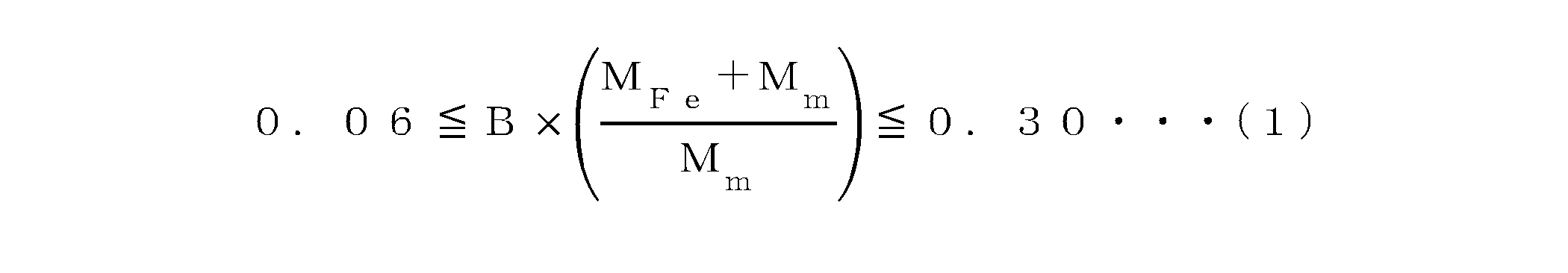
相対バインダー樹脂量が0.06を下回ると、バインダー成分添加量が少なくなりすぎる。溶射火炎の温度が過度に高くなるため、真球状の粒子であってもステップ構造が生成しにくくなる。一方で相対バインダー樹脂量が0.30を上回ると、バインダー成分添加量が多すぎる。そのため溶射火炎の温度が下がりすぎてしまい、真球状の粒子のみならず不定形の粒子が大量に生成してしまう。相対バインダー樹脂量は0.07以上0.20以下であることがより好ましい。If the relative binder resin amount falls below 0.06, the amount of binder component added will be too small. This will cause the temperature of the thermal spray flame to become excessively high, making it difficult to produce a step structure even in spherical particles. On the other hand, if the relative binder resin amount exceeds 0.30, the amount of binder component added will be too large. This will cause the temperature of the thermal spray flame to drop too much, resulting in the production of large amounts of not only spherical particles but also amorphous particles. It is more preferable that the relative binder resin amount is between 0.07 and 0.20.
<溶射>
次に得られた造粒物を溶射して溶射物とする。溶射では、燃焼ガスと酸素との混合気体を可燃性ガス燃焼炎として用いることができる。燃焼ガスと酸素との容量比は、1:3.5~1:6.0が好ましく、1:4.9~1:6.0がより好ましく、1:4.9~1:5.3が特に好ましい。これにより揮発した材料が凝縮し、粒径が小さい粒子の形成を好適に進行させることができる。例えば燃焼ガス7Nm3/時に対して酸素35Nm3/時の割合(燃焼ガスと酸素との容量比が1:5)とする条件が挙げられる。
<Thermal spraying>
Next, the obtained granules are thermally sprayed to obtain a thermal spray material. In thermal spraying, a mixture of combustion gas and oxygen can be used as the combustible gas combustion flame. The volume ratio of the combustion gas to oxygen is preferably 1:3.5 to 1:6.0, more preferably 1:4.9 to 1:6.0, and particularly preferably 1:4.9 to 1:5.3. This allows the volatilized material to condense, and the formation of particles with small diameters can be favorably promoted. For example, a ratio of 7 Nm 3 /hour of combustion gas to 35 Nm 3 /hour of oxygen (volume ratio of combustion gas to oxygen is 1:5) can be mentioned.
燃焼ガスや酸素が過度に多い条件では、燃焼に使われなかったガスや酸素が燃焼により発生した熱を奪い、火炎の温度が下がる恐れがある。したがってそのような条件で溶射を行うことは好ましくない。燃焼に使われなかった余剰燃焼ガス量は、供給された燃焼ガス量の20体積%以下であることが好ましい。また燃焼に使われなかった余剰酸素量は、供給された酸素量の20体積%以下であることが好ましい。 Under conditions where there is an excessive amount of combustion gas or oxygen, the gas and oxygen not used in the combustion may take away the heat generated by the combustion, causing the flame temperature to drop. Therefore, it is not preferable to perform thermal spraying under such conditions. It is preferable that the amount of excess combustion gas not used in the combustion is 20 volume % or less of the amount of combustion gas supplied. It is also preferable that the amount of excess oxygen not used in the combustion is 20 volume % or less of the amount of oxygen supplied.
溶射に用いる燃焼ガスとして、プロパンガス、プロピレンガス、アセチレンガス等の可燃性ガスが挙げられ、中でもプロパンガスが好適である。造粒物を可燃性ガス中に搬送するために、窒素、酸素、空気等の搬送ガスを用いることができる。搬送される造粒物の流速は、20~60m/秒が好ましい。溶射温度は、1000~3500℃が好ましく、2000~3500℃がより好ましい。このような条件を満足することで、揮発した材料が凝縮し、粒径が比較的小さい粒子の形成をさらに好適に進行させることができる。また得られるフェライト粒子の形状をさらに好適に調整することができる。 Combustion gases used in thermal spraying include flammable gases such as propane gas, propylene gas, and acetylene gas, with propane gas being preferred. A carrier gas such as nitrogen, oxygen, or air can be used to transport the granulated material into the flammable gas. The flow rate of the transported granulated material is preferably 20 to 60 m/sec. The thermal spraying temperature is preferably 1000 to 3500°C, and more preferably 2000 to 3500°C. By satisfying these conditions, the volatilized material condenses, and the formation of particles with a relatively small particle size can be more suitably advanced. The shape of the resulting ferrite particles can also be more suitably adjusted.
次に溶射によりフェライト化した粒子に、冷却用ガスを導入して急冷及び凝固し、凝固した粒子をサイクロン又はフィルターで回収する。そして回収したフェライト粒子を、必要に応じて分級すればよい。冷却用ガスとして室温の大気を用いることができる。あるいは急冷と酸化を防止するため、室温よりも温度が低い空気や不活性ガス(窒素ガス、ヘリウムガス、アルゴンガス等)も用いることもできる。分級では、既存の風力分級(気流分級)、メッシュ濾過、ふるい(篩)分級、沈降などの手法を用いて、所望の粒径に粒度調整する。なおサイクロン等の気流分級で粒径の大きい粒子を1つの工程の中で分離して回収することも可能である。Next, a cooling gas is introduced into the particles ferrite-formed by thermal spraying to rapidly cool and solidify them, and the solidified particles are collected in a cyclone or filter. The collected ferrite particles can then be classified as necessary. Air at room temperature can be used as the cooling gas. Alternatively, air or inert gases (nitrogen gas, helium gas, argon gas, etc.) at temperatures lower than room temperature can be used to prevent rapid cooling and oxidation. For classification, the particle size is adjusted to the desired particle size using existing techniques such as air classification (airflow classification), mesh filtration, sieve classification, and sedimentation. It is also possible to separate and collect large particles in a single process by airflow classification using a cyclone or other method.
ステップ構造を備えるフェライト粒子(球状様ステップ粒子)を得るためには、造粒物を所定の条件で溶射することが重要である。溶射時に造粒物の全体が溶融した後に急冷される。その詳細なメカニズムは不明であるが、高温溶融時にフェライトの結晶構造を反映した多角形状のステップ構造が粒子表面に形成され、急冷することでこの構造が保持されたまま冷却されるのではないかと推察している。すなわちバインダーを含有する造粒物が溶射されることで、バインダーが分解されながら原料一次粒子がフェライト粒子(球状様ステップ粒子)に変化してゆく。バインダー分解は吸熱反応であり、ステップ構造を形成しても必要以上に熱が加わりにくい。そのため、明確なステップ構造が生成及び維持されやすいと推察される。一方で、造粒物がバインダーを含有しない場合や非常に少ない場合には、火炎からの過剰な熱を受け取る。そのため、たとえステップ構造が形成されたとしても、時間の経過とともにステップ構造が粒子全体で維持されなくなり、局所的に消滅してしまう。造粒物のバインダー含有量は、造粒物の質量に対して0.007質量%以上が好ましい。一方で造粒物のバインダー含有量が過剰な場合には、吸熱反応が大きくなりすぎるため真球状にならない粒子が生成しやすくなる。造粒物のバインダー含有量は、造粒物の質量に対して0.100質量%以下が好ましく、0.050質量%以下がより好ましい。In order to obtain ferrite particles with a step structure (spherical step particles), it is important to spray the granulated material under specified conditions. The entire granulated material is melted during spraying and then rapidly cooled. Although the detailed mechanism is unknown, it is speculated that a polygonal step structure reflecting the crystal structure of ferrite is formed on the particle surface during high-temperature melting, and this structure is maintained when the granulated material is rapidly cooled. In other words, when the granulated material containing a binder is sprayed, the binder is decomposed and the raw material primary particles are changed into ferrite particles (spherical step particles). Binder decomposition is an endothermic reaction, and it is difficult to apply more heat than necessary even if a step structure is formed. Therefore, it is speculated that a clear step structure is easily generated and maintained. On the other hand, if the granulated material does not contain a binder or contains very little binder, it receives excessive heat from the flame. Therefore, even if a step structure is formed, the step structure will not be maintained throughout the particle as time passes and will disappear locally. The binder content of the granulated material is preferably 0.007% by mass or more relative to the mass of the granulated material. On the other hand, if the binder content of the granulated material is excessive, the endothermic reaction becomes too large, and particles that are not perfectly spherical tend to be generated. The binder content of the granulated material is preferably 0.100% by mass or less, more preferably 0.050% by mass or less, based on the mass of the granulated material.
また造粒物を溶融温度以下の温度で焼成してフェライト粒子とした場合には、多角形状のステップ構造が形成されにくく、仮に形成されたとしても、徐冷することでステップ構造が消失してしまうと考えている。例えば、特許文献6では原料混合物を顆粒化した後に1000℃以下の温度で焼成して粒子表面にステップ状の凹凸を有するキャリア芯材を製造している(特許文献6の請求項1)。しかしながら、このステップ状の凹凸は同心円状であり、本実施形態が対象とするステップ構造とは形状が異なる。 In addition, when the granulated material is sintered at a temperature below the melting temperature to produce ferrite particles, it is believed that a polygonal step structure is difficult to form, and even if it is formed, the step structure disappears when cooled slowly. For example, in Patent Document 6, a raw material mixture is granulated and then sintered at a temperature below 1000°C to produce a carrier core material having step-like irregularities on the particle surface (Claim 1 of Patent Document 6). However, this step-like irregularity is concentric and has a different shape from the step structure targeted by this embodiment.
また溶射時の条件も重要である。すなわち溶射火炎中を通過する際の温度(原料粒子に対する与える熱量)から室温まで冷却される間の時間によって、ステップ構造発現のメカニズムが変化する。特に高い温度の火炎を通過した原料一次粒子が急冷されることでステップ構造が発現する。同じ温度の火炎であっても原料一次粒子の単位時間当たりの通過数(時間当たりの処理量)が多くなるとステップ構造は発現しにくくなる。そのためステップ構造を発現させる観点から、溶射原料の供給量は少ない方が好ましい。例えば、供給量は、20kg/時間以下が好ましく、10kg/時間以下がより好ましく、5kg/時間未満が最も好ましい。The conditions during thermal spraying are also important. That is, the mechanism of the appearance of the step structure changes depending on the time it takes for the raw material particles to cool down from the temperature when passing through the thermal spray flame (the amount of heat given to the raw material particles) to room temperature. In particular, the step structure appears when the primary raw material particles that have passed through a flame of high temperature are rapidly cooled. Even with the same temperature flame, the step structure becomes less likely to appear if the number of passes per unit time of the primary raw material particles (the amount of processing per hour) increases. Therefore, from the viewpoint of appearing the step structure, it is preferable to supply a small amount of raw material for thermal spraying. For example, the supply amount is preferably 20 kg/hour or less, more preferably 10 kg/hour or less, and most preferably less than 5 kg/hour.
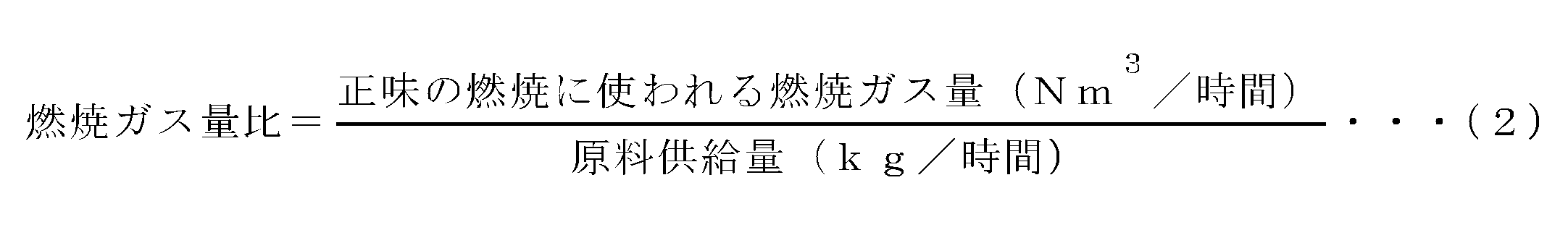
また燃焼ガス量比は1.05以上2.00以下であることが好ましい。ここで、燃焼ガス量比は、原料供給量(kg/時間)に対する正味の燃焼に使われる燃焼ガス量(Nm3/時間)の比であり、下記(2)式にしたがって求められる。 The combustion gas amount ratio is preferably 1.05 or more and 2.00 or less. Here, the combustion gas amount ratio is the ratio of the amount of combustion gas ( Nm3 /hour) used for net combustion to the amount of raw material supplied (kg/hour), and is calculated according to the following formula (2).
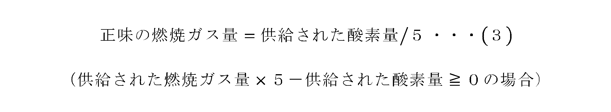
また正味の燃焼に使われる燃焼ガス量(Nm3/時間)は、下記(3)式又は下記(4)式にしたがって求められる。 The amount of combustion gas used for net combustion (Nm 3 /hour) is calculated according to the following formula (3) or (4).

3.フェライト樹脂複合材料
本実施形態のフェライト樹脂複合材料は、上記フェライト粉末と樹脂とを含む。この複合材料によれば、成形性及び充填性を損なうことなく、フェライト粒子の脱落が抑制される。
3. Ferrite Resin Composite Material The ferrite resin composite material of the present embodiment includes the above-mentioned ferrite powder and a resin. This composite material prevents the ferrite particles from falling off without impairing moldability and packing ability.
複合材料を構成する樹脂として、例えば、エポキシ樹脂、ウレタン樹脂、アクリル樹脂、シリコーン樹脂、ポリアミド樹脂、ポリイミド樹脂、ポリアミドイミド樹脂、フッ素樹脂又はこれらの組み合わせなどが挙げられる。ここでシリコーン樹脂は、アクリル、ウレタン、エポキシ及び/又はフッ素等で変性した変性シリコーン樹脂であってもよい。 Examples of resins constituting the composite material include epoxy resins, urethane resins, acrylic resins, silicone resins, polyamide resins, polyimide resins, polyamideimide resins, fluororesins, and combinations of these. Here, the silicone resin may be a modified silicone resin modified with acrylic, urethane, epoxy, and/or fluorine.
複合材料は、フェライト粉末と樹脂以外の他の成分を含んでもよい。このような成分として、例えば、溶媒、充填剤(有機充填剤、無機充填剤)、可塑剤、酸化防止剤、分散剤、顔料等の着色剤及び/又は熱伝導性粒子などが挙げられる。The composite material may contain components other than the ferrite powder and the resin. Such components include, for example, solvents, fillers (organic fillers, inorganic fillers), plasticizers, antioxidants, dispersants, colorants such as pigments, and/or thermally conductive particles.
複合材料中の全固形分に対するフェライト粉末の割合は、50~95質量%が好ましく、80~95質量%がより好ましい。また複合材料中の全固形分に対する樹脂の割合は、5~50質量%が好ましく、5~20質量%がより好ましい。フェライト粉末や樹脂の割合を上記範囲内とすることで、複合材料中のフェライト粉末の分散安定性、並びに複合材料の保存安定性及び成形性が優れたものになるとともに、複合材料を成形して得られる複合体(成形体)の機械的強度や電磁波遮蔽性能等の特性がより優れたものになる。The ratio of ferrite powder to the total solid content in the composite material is preferably 50 to 95 mass%, more preferably 80 to 95 mass%. The ratio of resin to the total solid content in the composite material is preferably 5 to 50 mass%, more preferably 5 to 20 mass%. By setting the ratios of ferrite powder and resin within the above ranges, the dispersion stability of the ferrite powder in the composite material, as well as the storage stability and moldability of the composite material, are excellent, and the mechanical strength, electromagnetic wave shielding performance, and other properties of the composite (molded body) obtained by molding the composite material are improved.
4.電磁波シールド材、電子材料、電子部品
本実施形態の電磁波シールド材、電子材料又は電子部品は、上記フェライト樹脂複合材料を含む。電磁波シールド材、電子材料又は電子部品は、複合材料を公知の手法で成形して作製すればよい。成形手法は、特に限定されるものではなく、例えば圧縮成形、押出成形、射出成形、ブロー成形又はカレンダー成形が挙げられる。また複合材料の塗膜を基体上に形成する手法であってもよい。
4. Electromagnetic shielding material, electronic material, and electronic component The electromagnetic shielding material, electronic material, or electronic component of the present embodiment includes the above-mentioned ferrite resin composite material. The electromagnetic shielding material, electronic material, or electronic component may be produced by molding the composite material by a known method. The molding method is not particularly limited, and examples thereof include compression molding, extrusion molding, injection molding, blow molding, and calendar molding. Alternatively, a coating film of the composite material may be formed on a substrate.
このように、本実施形態のフェライト粉末は、特定の形状を有し且つ特定のステップ構造をその表面に備えるフェライト粒子を含むことを特徴としている。このフェライト粉末は、電磁波シールド材料、電子材料及び/又は電子部品の用途に好適である。また本実施形態のフェライト粉末、フェライト樹脂複合材料並びに電磁波シールド材料、電子材料又は電子部品は、成形性及び充填性を損なうことなく、フェライト粒子の脱落を抑制することが可能となる。これに対して、特許文献1~5にはフェライト粒子の表面構造に関する記載はなく、粒子脱落を課題とするものではない。また特許文献6に開示されるキャリア芯材は、その表面ステップ状凹凸が同心円状であり、本実施形態が対象とするステップ構造とは形状が異なる。またその課題はキャリア芯材の帯電付与能力の向上であり(特許文献6の[0026])、粒子脱落とは無関係である。 Thus, the ferrite powder of this embodiment is characterized by including ferrite particles having a specific shape and a specific step structure on its surface. This ferrite powder is suitable for use as an electromagnetic shielding material, electronic material, and/or electronic component. In addition, the ferrite powder, ferrite resin composite material, and electromagnetic shielding material, electronic material, or electronic component of this embodiment can suppress the ferrite particle from falling off without impairing moldability and filling properties. In contrast, Patent Documents 1 to 5 do not describe the surface structure of ferrite particles, and do not address particle falling off as an issue. In addition, the carrier core material disclosed in Patent Document 6 has a concentric step-like surface irregularity, which is different in shape from the step structure targeted by this embodiment. In addition, the issue is to improve the charging ability of the carrier core material ([0026] of Patent Document 6), and is unrelated to particle falling off.
本実施形態を、以下の例によって、さらに具体的に説明する。This embodiment will be explained in more detail with reference to the following example.
(1)フェライト粉末の作製
例1
<原料混合>
原料として、酸化鉄(Fe2O3)と四酸化三マンガン(Mn3O4)とを用い、鉄(Fe)とマンガン(Mn)のモル比が、Fe:Mn=7.8:1となるように秤量し、ヘンシェルミキサーを用いて混合した。
(1) Preparation of Ferrite Powder Example 1
<Raw material mixing>
As raw materials, iron oxide (Fe 2 O 3 ) and trimanganese tetroxide (Mn 3 O 4 ) were used, and were weighed out so that the molar ratio of iron (Fe) to manganese (Mn) was Fe:Mn=7.8:1, and mixed using a Henschel mixer.
<仮焼成及び粉砕>
得られた混合物を、ロータリーキルンを用いて仮焼成した。仮焼成は、混合物を大気中900℃で4時間保持することにより行った。得られた仮焼成物を、乾式ビーズミル(3/16インチの鋼球ビーズ)を用いて粗粉砕し、その後、水を加えて、湿式ビーズミル(0.65mmのジルコニアビーズ)を用いて微粉砕した。粉砕粉の粒径は、2.26μmであった。
<Pre-firing and grinding>
The resulting mixture was pre-fired using a rotary kiln. The pre-fired mixture was held in air at 900°C for 4 hours. The pre-fired product was coarsely pulverized using a dry bead mill (3/16 inch steel ball beads), and then water was added and the product was finely pulverized using a wet bead mill (0.65 mm zirconia beads). The particle size of the pulverized powder was 2.26 μm.
<造粒>
得られたスラリーに、バインダーとしてポリビニルアルコール(PVA、10%水溶液)を固形分換算で0.017質量%加えた。その後、バインダーを加えたスラリーを、スプレードライヤーを用いて造粒した。
<Granulation>
To the obtained slurry, polyvinyl alcohol (PVA, 10% aqueous solution) was added as a binder in an amount of 0.017% by mass in terms of solid content. Then, the slurry to which the binder was added was granulated using a spray dryer.
<溶射>
得られた造粒物を可燃性ガス燃焼炎中で溶射及び急冷した。溶射は、プロパンガス流量7.0m3/時間、酸素流量35m3/時間、原料供給速度4.5kg/時間の条件で行った。また溶射直後の燃焼ガスに冷却用の大気を導入して溶射物を急冷し、急冷した溶射物を気流の下流側に設けたサイクロンで回収した。得られた溶射物から篩を用いて粗粉を取り除き、さらに分級装置により微粉を除去して、複数個のマンガン(Mn)系フェライト粒子からなるフェライト粉末を得た。
<Thermal spraying>
The obtained granules were sprayed and quenched in a combustible gas combustion flame. The spraying was performed under the conditions of a propane gas flow rate of 7.0 m3 /h, an oxygen flow rate of 35 m3 /h, and a raw material supply rate of 4.5 kg/h. The sprayed material was quenched by introducing air for cooling into the combustion gas immediately after spraying, and the quenched sprayed material was collected in a cyclone installed downstream of the air flow. Coarse powder was removed from the obtained sprayed material using a sieve, and fine powder was further removed using a classification device to obtain a ferrite powder consisting of a plurality of manganese (Mn)-based ferrite particles.
例2
溶射直後の燃焼ガスに冷却用の大気を導入して溶射物を急冷し、急冷した溶射物を気流の下流側に設けたバグフィルターで回収した。得られた溶射物から気流分級により粗粉を取り除くものの、微粉除去は行わなかった。それ以外は例1と同様にしてフェライト粉末の作製を行った。
Example 2
Immediately after spraying, air for cooling was introduced into the combustion gas to rapidly cool the sprayed material, and the rapidly cooled sprayed material was collected in a bag filter installed downstream of the air flow. Coarse powder was removed from the resulting sprayed material by air flow classification, but fine powder was not removed. Ferrite powder was produced in the same manner as in Example 1.
例3
原料混合時に、鉄(Fe)とマンガン(Mn)のモル比が、Fe:Mn=3.0:1となるように秤量した。また造粒時に、スラリーに、バインダーとしてポリビニルアルコール(PVA、10%水溶液)を固形分換算で0.044質量%加えた。それ以外は例1と同様にしてフェライト粉末の作製を行った。例3では仮焼成及び粉砕後の粉砕粉の粒径は、2.52μmであった。
Example 3
When the raw materials were mixed, iron (Fe) and manganese (Mn) were weighed so that the molar ratio of Fe:Mn was 3.0:1. During granulation, 0.044 mass% of polyvinyl alcohol (PVA, 10% aqueous solution) was added as a binder to the slurry in terms of solid content. Otherwise, ferrite powder was produced in the same manner as in Example 1. In Example 3, the particle size of the pulverized powder after calcination and pulverization was 2.52 μm.
例4
溶射直後の燃焼ガスに冷却用の大気を導入して溶射物を急冷し、急冷した溶射物を気流の下流側に設けたバグフィルターで回収した。得られた溶射物から気流分級による粗粉を取り除くものの、微粉除去は行わなかった。それ以外は例3と同様にしてフェライト粉末の作製を行った。
Example 4
Immediately after spraying, air for cooling was introduced into the combustion gas to rapidly cool the sprayed material, and the rapidly cooled sprayed material was collected in a bag filter installed downstream of the air flow. Although coarse powder was removed from the obtained sprayed material by air flow classification, fine powder removal was not performed. Ferrite powder was produced in the same manner as in Example 3.
例5
原料混合時に、鉄(Fe)とマンガン(Mn)のモル比が、Fe:Mn=14.0:1となるように秤量した。また造粒時に、スラリーに、バインダーとしてポリビニルアルコール(PVA、10%水溶液)を固形分換算で0.010質量%加えた。それ以外は例1と同様にしてフェライト粉末の作製を行った。例5では仮焼成及び粉砕後の粉砕粉の粒径は、2.01μmであった。
Example 5
When the raw materials were mixed, iron (Fe) and manganese (Mn) were weighed so that the molar ratio of Fe:Mn was 14.0:1. During granulation, 0.010 mass% of polyvinyl alcohol (PVA, 10% aqueous solution) was added as a binder to the slurry in terms of solid content. Otherwise, ferrite powder was produced in the same manner as in Example 1. In Example 5, the particle size of the pulverized powder after calcination and pulverization was 2.01 μm.
例6
溶射を、プロパンガス流量7.5m3/時間、酸素流量35m3/時間、原料供給速度4.5kg/時間の条件で行った。溶射直後の燃焼ガスに冷却用の大気を導入して溶射物を急冷し、急冷した溶射物を気流の下流側に設けたバグフィルターで回収した。得られた溶射物から気流分級により粗粉を取り除くものの、微粉除去は行わなかった。それ以外は例5と同様にしてフェライト粉末の作製を行った。
Example 6
Thermal spraying was carried out under the conditions of a propane gas flow rate of 7.5 m3 /hour, an oxygen flow rate of 35 m3 /hour, and a raw material supply rate of 4.5 kg/hour. Air for cooling was introduced into the combustion gas immediately after thermal spraying to quench the thermal sprayed material, and the quenched thermal sprayed material was collected in a bag filter installed downstream of the air flow. Coarse powder was removed from the obtained thermal sprayed material by air flow classification, but fine powder was not removed. Ferrite powder was produced in the same manner as in Example 5 except for the above.
例7
溶射を、プロパンガス流量7.5m3/時間、酸素流量37.5m3/時間、原料供給速度6kg/時間の条件で行った。また溶射直後の燃焼ガスに冷却用の大気を導入して溶射物を急冷し、急冷した溶射物を気流の下流側に設けたサイクロンで回収した。それ以外は例1と同様にしてフェライト粉末の作製を行った。
Example 7
The thermal spraying was carried out under the conditions of a propane gas flow rate of 7.5 m3 /hour, an oxygen flow rate of 37.5 m3 /hour, and a raw material supply rate of 6 kg/hour. In addition, air for cooling was introduced into the combustion gas immediately after thermal spraying to quench the thermal sprayed material, and the quenched thermal sprayed material was collected in a cyclone installed downstream of the air flow. Ferrite powder was produced in the same manner as in Example 1 except for the above.
例8
溶射直後の燃焼ガスに冷却用の大気を導入して溶射物を急冷し、急冷した溶射物を気流の下流側に設けたバグフィルターで回収した。得られた溶射物から気流分級により粗粉を取り除くものの、微粉除去は行わなかった。それ以外は例7と同様にしてフェライト粉末の作製を行った。
Example 8
Immediately after spraying, air for cooling was introduced into the combustion gas to rapidly cool the sprayed material, and the rapidly cooled sprayed material was collected in a bag filter installed downstream of the air flow. Although coarse powder was removed from the obtained sprayed material by air flow classification, fine powder was not removed. Ferrite powder was produced in the same manner as in Example 7.
例9(比較)
溶射の代わりに、造粒物の脱バインダー、本焼成を行い、その後、得られた焼成物を解砕して、解砕物から気流分級により粗粉及び微粉を除去した。脱バインダー及び本焼成は、造粒物を大気中650℃で4時間保持し、その後、酸素0体積%の雰囲気下1250℃で4時間保持することにより行った。また解砕はハンマークラッシャーを用いて行った。それ以外は例1と同様にしてフェライト粉末の作製を行った。
Example 9 (Comparative)
Instead of thermal spraying, the granulated material was debindered and sintered, and then the sintered material was crushed and coarse powder and fine powder were removed from the crushed material by air classification. The debindering and sintering were performed by holding the granulated material in air at 650°C for 4 hours, and then holding it in an atmosphere of 0% oxygen by volume at 1250°C for 4 hours. Crushing was performed using a hammer crusher. Ferrite powder was produced in the same manner as in Example 1 except for the above.
例1~例9について、フェライト粉末の製造条件を表1に示す。The manufacturing conditions for ferrite powder for Examples 1 to 9 are shown in Table 1.
(2)複合材料の作製
例1~例9で得られたフェライト粉末を用いて、フェライト樹脂複合材料を作製した。複合材料の作製は、次のようにして行った。得られたフェライト粉末と市販のエポキシ樹脂とを、フェライト粉末の体積が60体積%となるように秤量し、自転公転式ミキサーにてペースト化した。また粘度計を用いてペースト粘度を測定した。得られたペーストをシリコーン樹脂の型に流し込んだ後に熱硬化し、脱離粒子評価用サンプル(複合材料)を作製した。
(2) Preparation of Composite Material Ferrite resin composite materials were prepared using the ferrite powders obtained in Examples 1 to 9. The composite materials were prepared as follows. The obtained ferrite powders and commercially available epoxy resin were weighed out so that the volume of the ferrite powder was 60 volume %, and the mixture was made into a paste using a planetary centrifugal mixer. The viscosity of the paste was measured using a viscometer. The obtained paste was poured into a silicone resin mold and then thermally cured to prepare a sample (composite material) for evaluating detached particles.
(3)評価
例1~例9で得られたフェライト粉末及び複合材料について、各種特性の評価を以下の通り行った。
(3) Evaluation The ferrite powders and composite materials obtained in Examples 1 to 9 were evaluated for various properties as follows.
<元素分析‐金属成分含有量>
フェライト粉末の金属成分含有量を、次のようにして測定した。まず試料(フェライト粉末)0.2gを秤量し、これに純水60mlと1Nの塩酸20ml及び1Nの硝酸20mlを加えた後に加熱して、試料を完全溶解させた水溶液を調整した。得られた水溶液をICP分析装置(株式会社島津製作所、ICPS-10001V)にセットし、金属成分含有量を測定した。
<Elemental analysis - metal component content>
The metal content of the ferrite powder was measured as follows. First, 0.2 g of the sample (ferrite powder) was weighed, and 60 ml of pure water, 20 ml of 1N hydrochloric acid, and 20 ml of 1N nitric acid were added to the sample, followed by heating to prepare an aqueous solution in which the sample was completely dissolved. The resulting aqueous solution was placed in an ICP analyzer (Shimadzu Corporation, ICPS-10001V) to measure the metal content.
<粒子の表面構造‐Ps>
フェライト粉末中の粒子の表面構造を、次のようにして評価した。まず走査電子顕微鏡(SEM;日立ハイテクノロジーズ社、SU-8020)を用いてフェライト粉末を観察した。観察の際に、平均粒径2μm以上の粒子は倍率を50000倍に設定し、平均粒径2μm未満の粒子は200000倍に設定した。そしていずれの場合も水平フェレ径0.3μm以上の粒子が、視野中に1~30個、好ましくは1~10個入る状態で撮影した。
<Particle surface structure - Ps>
The surface structure of particles in the ferrite powder was evaluated as follows. First, the ferrite powder was observed using a scanning electron microscope (SEM; Hitachi High-Technologies Corporation, SU-8020). During observation, the magnification was set to 50,000 times for particles with an average particle size of 2 μm or more, and 200,000 times for particles with an average particle size of less than 2 μm. In either case, the image was taken with 1 to 30 particles, preferably 1 to 10 particles, having a horizontal Feret diameter of 0.3 μm or more in the field of view.
撮影はランダムに10視野分を撮影し、水平フェレ径0.3μm以上の粒子について多角形状ステップの有無を確認した。そして球状様ステップ粒子の割合(Ps)を、下記(5)式にしたがって算出した。なお水平フェレ径0.3μm未満の粒子は、撮影時に電子線が粒子を透過してしまいステップの有無を判定できない恐れがある。そのため評価対象から外した。 Photographs were taken randomly from 10 fields of view, and the presence or absence of polygonal steps was confirmed for particles with a horizontal Feret diameter of 0.3 μm or more. The proportion of spherical-like step particles (Ps) was then calculated according to the following formula (5). Note that for particles with a horizontal Feret diameter of less than 0.3 μm, the electron beam may pass through the particle during photography, making it impossible to determine whether or not there are steps. For this reason, they were excluded from the evaluation.

ここでNiはi番目の視野で撮影された水平フェレ径0.3μm以上の粒子の数であり、niはi番目の視野に撮影された粒子のうち、球状様ステップを有する粒子の数である。また部分的に撮影視野の外側に出ている粒子も1粒子としてカウントした。 Here, Ni is the number of particles with a horizontal Feret diameter of 0.3 μm or more photographed in the i-th field of view, and Ni is the number of particles with spherical-like steps among the particles photographed in the i-th field of view. Also, particles that are partially outside the photographed field of view were counted as one particle.
<粒子の表面構造‐Hs>
走査電子顕微鏡(SEM)での観察の際に、倍率を200000倍に設定し、1~30個、好ましくは1~10個の球状様ステップ粒子を、これらが視野中央に入るように撮影した。そしてSEM写真のスケールからステップの平均間隔(Hs)を下記(6)式にしたがって求めた。
<Particle surface structure - Hs>
In the observation with a scanning electron microscope (SEM), the magnification was set to 200,000 times, and 1 to 30, preferably 1 to 10, spherical-like step particles were photographed so that they were in the center of the field of view. The average interval (Hs) of the steps was calculated from the scale of the SEM photograph according to the following formula (6).

図1に球状様ステップ粒子のSEM写真の一例を示す。図中の矢印(→)は、平行に並んでいるステップに対する垂直方向を表す。また図の数字(1、2、3・・・)は各ステップを表す。なお撮影はステップが判別できるように行えばよく、粒子全体が1視野に入る必要はない。またHsの算出に際してステップは1粒子の任意の1か所を選べばよい。方向の異なるステップが複数存在する場合はおおむねその粒子を代表するステップから算出してもよい。ステップの数は4以上であればよい。 Figure 1 shows an example of an SEM photograph of a spherical-like stepped particle. The arrow (→) in the photograph indicates the perpendicular direction to the steps arranged in parallel. The numbers in the photograph (1, 2, 3, etc.) represent each step. The photograph should be taken so that the steps can be distinguished; it is not necessary for the entire particle to fit within one field of view. When calculating Hs, any one step on a particle can be selected. If there are multiple steps with different directions, calculations can be made from the step that is roughly representative of the particle. The number of steps should be four or more.
<形状係数‐平均粒径2μm以上の場合>
平均粒径2μm以上の粒子については、フェライト粉末の形状係数(SF-1及びSF-2)を、粒子画像分析装置(Malvern Panalytical社、モフォロギG3)を用いて求めた。まず粒子画像分析装置を用いてフェライト粉末を解析した。解析の際には粉末中30000粒子について1粒子ごとに画像解析を行い、円形度(Circularity)、周囲長(Perimeter)、円相当径(CE Diameter)を自動測定した。この際、倍率10倍の対物レンズを使用した。また装置付属の分散用治具を用いてスライドガラス上に粒子を分散させた。この際、サンプル量:3mm3、分散圧:5barの条件で粒子を分散させた。
<Shape factor - average particle size 2 μm or more>
For particles with an average particle size of 2 μm or more, the shape factors (SF-1 and SF-2) of the ferrite powder were determined using a particle image analyzer (Malvern Panalytical, Morphologi G3). First, the ferrite powder was analyzed using a particle image analyzer. During the analysis, image analysis was performed on each of 30,000 particles in the powder, and the circularity, perimeter, and circle equivalent diameter (CE diameter) were automatically measured. At this time, an objective lens with a magnification of 10 times was used. In addition, the particles were dispersed on a slide glass using a dispersion jig attached to the device. At this time, the particles were dispersed under the conditions of sample amount: 3 mm 3 and dispersion pressure: 5 bar.
得られたデータのうち、体積平均粒径±5%以内の粒子のデータの平均を平均円形度、平均周囲長(Perimeter)、平均円相当径(CE Diameter)とし、下記(7)式及び下記(8)式にしたがって、SF-1及びSF-2を算出した。Of the obtained data, the averages of the data for particles within ±5% of the volume average particle size were used as the average circularity, average perimeter, and average circular equivalent diameter (CE diameter), and SF-1 and SF-2 were calculated according to the following formulas (7) and (8).

<形状係数‐平均粒径2μm未満の場合>
平均粒径2μm未満の粒子については、フェライト粉末の形状係数(SF-1及びSF-2)を、FE-SEM(電界放出型走査電子顕微鏡)を用いて求めた。まずFE-SEMを用いてフェライト粉末の撮影を複数視野で行った。撮影は倍率100000倍の条件で行った。その後、画像解析ソフト(Image-Pro Plus)を用いて画像解析を行った。解析の際には体積平均粒径±5%の円相当径の100粒子を選択し、粒子ごとに解析した。そして最大長(水平フェレ径)R(単位:μm)、投影周囲長L(単位:μm)及び投影面積S(単位:μm2)、円相当径r(単位:μm)を測定した。
<Shape factor - average particle size less than 2 μm>
For particles with an average particle size of less than 2 μm, the shape factors (SF-1 and SF-2) of the ferrite powder were determined using a FE-SEM (field emission scanning electron microscope). First, images of the ferrite powder were taken in multiple fields of view using the FE-SEM. The images were taken at a magnification of 100,000 times. Then, image analysis was performed using image analysis software (Image-Pro Plus). During the analysis, 100 particles with a circle-equivalent diameter of ±5% of the volume average particle size were selected and analyzed for each particle. Then, the maximum length (horizontal Feret diameter) R (unit: μm), projected perimeter L (unit: μm), projected area S (unit: μm 2 ), and circle-equivalent diameter r (unit: μm) were measured.
次いで下記(9)式及び下記(10)式にしたがって各粒子のSF-1及びSF-2を算出し、それぞれの平均値をフェライト粉末のSF-1及びSF-2とした。Next, SF-1 and SF-2 of each particle were calculated according to the following formulas (9) and (10), and the respective average values were designated as SF-1 and SF-2 of the ferrite powder.


<異形粒子割合>
フェライト粉末中の異形粒子割合を次のようにして求めた。粒子画像分析装置を用いた解析の際に、円形度0.965以上1.000以下の粒子の個数Nと円形度0.950以上0.965未満の粒子の個数nをカウントし、異形粒子割合を、下記(11)式にしたがって算出した。なお円形度0.950未満の粒子は凝集した粒子である恐れがある。そのため、このような粒子を評価対象から外した。
<Ratio of irregular particles>
The ratio of irregularly shaped particles in the ferrite powder was determined as follows. During analysis using a particle image analyzer, the number N of particles with a circularity of 0.965 to 1.000 and the number n of particles with a circularity of 0.950 to less than 0.965 were counted, and the ratio of irregularly shaped particles was calculated according to the following formula (11). Note that particles with a circularity of less than 0.950 may be aggregated particles. Therefore, such particles were excluded from the evaluation.
<タップ密度>
フェライト粉末のタップ密度を、USPタップ密度測定装置(ホソカワミクロン株式会社、パウダテスタPT-X)を用いて、JIS Z 2512-2012に準拠して測定した。
<Tap density>
The tap density of the ferrite powder was measured using a USP tap density measuring device (Powder Tester PT-X, manufactured by Hosokawa Micron Corporation) in accordance with JIS Z 2512-2012.
<真比重>
フェライト粉末の真比重を、ガス置換法を用いて、JIS Z8807:2012に準拠して測定した。具体的には全自動真密度測定装置(株式会社マウンテック、Macpycno)を用いて測定を行った。
<True specific gravity>
The true specific gravity of the ferrite powder was measured by a gas replacement method in accordance with JIS Z8807: 2012. Specifically, the measurement was performed using a fully automatic true density measuring device (Macpycno, Mountec Co., Ltd.).
<粒度分布>
フェライト粉末の粒度分布を、次のようにして測定した。まず試料(フェライト粉末)10g及び水80mlを100mlのビーカーに入れ、分散剤としてヘキサメタリン酸ナトリウムを2滴添加した。次いで超音波ホモジナイザー(株式会社エスエムテー、UH-150型)を用いて分散した。このとき超音波ホモジナイザーの出力レベルを4に設定して20秒間の分散を行った。その後、ピーカー表面にできた泡を取り除き、得られた分散液をレーザー回折式粒度分布測定装置(島津製作所株式会社、SALD-7500nano)に導入して測定した。測定条件は、ポンプスピード7、内蔵超音波照射時間30、屈折率1.70-050iとした。この測定により体積粒度分布における10%径(D10)、50%径(体積平均粒径、D50)及び90%径(D90)を求めた。
<Particle size distribution>
The particle size distribution of the ferrite powder was measured as follows. First, 10 g of the sample (ferrite powder) and 80 ml of water were placed in a 100 ml beaker, and two drops of sodium hexametaphosphate were added as a dispersant. Then, the mixture was dispersed using an ultrasonic homogenizer (SMT Corporation, UH-150 type). At this time, the output level of the ultrasonic homogenizer was set to 4, and dispersion was performed for 20 seconds. After that, bubbles formed on the peaker surface were removed, and the obtained dispersion was introduced into a laser diffraction type particle size distribution measuring device (Shimadzu Corporation, SALD-7500nano) and measured. The measurement conditions were pump speed 7, built-in ultrasonic irradiation time 30, and refractive index 1.70-050i. From this measurement, the 10% diameter (D10), 50% diameter (volume average particle size, D50), and 90% diameter (D90) in the volume particle size distribution were obtained.
<BET比表面積>
フェライト粉末のBET比表面積を、比表面積測定装置(株式会社マウンテック、Macsorb HM model-1208)を用いて測定した。まずフェライト粉末約10gを薬包紙に載せ、真空乾燥機で脱気した。真空度が-0.1MPa以下であることを確認した後に、200℃で2時間加熱して、粒子表面に付着している水分を除去した。その後、水分が除去されたフェライト粉末(約0.5~4g)を測定装置専用の標準サンプルセルに入れ、精密天秤で正確に秤量した。続いて秤量したフェライト粒子を測定装置の測定ポートにセットして測定した。測定は1点法で行った。測定雰囲気は、温度10~30℃、相対湿度20~80%(結露なし)とした。
<BET specific surface area>
The BET specific surface area of the ferrite powder was measured using a specific surface area measuring device (Mountec Co., Ltd., Macsorb HM model-1208). First, about 10 g of the ferrite powder was placed on a medicine packing paper and degassed with a vacuum dryer. After confirming that the degree of vacuum was -0.1 MPa or less, the powder was heated at 200°C for 2 hours to remove moisture adhering to the particle surface. Then, the ferrite powder from which moisture had been removed (about 0.5 to 4 g) was placed in a standard sample cell dedicated to the measuring device and accurately weighed with a precision balance. The weighed ferrite particles were then set in the measuring port of the measuring device and measured. The measurement was performed using a one-point method. The measurement atmosphere was set at a temperature of 10 to 30°C and a relative humidity of 20 to 80% (no condensation).
<磁気特性‐飽和磁化、残留磁化及び保磁力>
フェライト粉末の磁気特性(飽和磁化、残留磁化及び保磁力)を、次のようにして測定した。まず内径5mm、高さ2mmのセルに試料(フェライト粉末)を詰めて、振動試料型磁気測定装置(東英工業株式会社、VSM-C7-10A)にセットした。印加磁場を加えて5kOeまで掃引し、次いで印加磁場を減少させて、ヒステリシスカーブを描かせた。このカーブのデータより、試料の飽和磁化σs、残留磁化σr及び保磁力Hcを求めた。
<Magnetic properties - saturation magnetization, residual magnetization and coercive force>
The magnetic properties (saturation magnetization, residual magnetization, and coercivity) of the ferrite powder were measured as follows. First, a sample (ferrite powder) was packed into a cell with an inner diameter of 5 mm and a height of 2 mm, and the cell was set in a vibrating sample magnetic measurement device (Toei Industry Co., Ltd., VSM-C7-10A). A magnetic field was applied and swept up to 5 kOe, and then the applied magnetic field was reduced to draw a hysteresis curve. From the data of this curve, the saturation magnetization σs, residual magnetization σr, and coercivity Hc of the sample were obtained.
<透磁率>
フェライト粉末の透磁率を、RFインピーダンス/マテリアル・アナライザ(アジレントテクノロジー株式会社、E4991A)と磁性材料測定電極(16454A)を用いて測定した。まず試料(フェライト粉末)9gとバインダー樹脂(Kynar301F:ポリフッ化ビニルデン)1gをポリエチレン製容器(内容量100ml)に入れ、ボールミルを用いて、回転数100rpmの条件で撹拌及び混合を行った。次に、得られた混合物(0.6g程度)をダイス(内径4.5mm、外径13mm)に充填し、プレス機を用いて40MPaの圧力で1分間の加圧を行って成形体とした。得られた成形体を、熱風乾燥機を用いて140℃で2時間の加熱硬化を行って測定用サンプルとした。得られた測定用サンプルをRFインピーダンス/マテリアル・アナライザにセットし、事前に測定しておいた測定用サンプルの外径、内径及び高さを入力した。測定の際、振幅を100mVとし、測定周波数1MHz~3GHzの範囲を対数スケールで掃引した。周波数100MHzでの複素透磁率の実部(μ’)及び虚部(μ’’)を求め、損失係数(tanδ)を、下記(12)式にしたがって算出した。
<Magnetic permeability>
The magnetic permeability of the ferrite powder was measured using an RF impedance/material analyzer (Agilent Technologies, Inc., E4991A) and a magnetic material measurement electrode (16454A). First, 9 g of the sample (ferrite powder) and 1 g of binder resin (Kynar301F: polyvinylidene fluoride) were placed in a polyethylene container (contents 100 ml), and a ball mill was used to stir and mix at a rotation speed of 100 rpm. Next, the resulting mixture (about 0.6 g) was filled into a die (inner diameter 4.5 mm, outer diameter 13 mm), and a press was used to pressurize the sample at a pressure of 40 MPa for 1 minute to obtain a molded body. The obtained molded body was heated and cured at 140 ° C. for 2 hours using a hot air dryer to obtain a measurement sample. The obtained measurement sample was set in an RF impedance/material analyzer, and the outer diameter, inner diameter, and height of the measurement sample that had been measured in advance were input. During the measurement, the amplitude was set to 100 mV, and the measurement frequency range was swept from 1 MHz to 3 GHz on a logarithmic scale. The real part (μ′) and imaginary part (μ″) of the complex permeability at a frequency of 100 MHz were obtained, and the loss factor (tan δ) was calculated according to the following formula (12).

<脱離粒子の割合>
複合材料(複合体)の脱離粒子の割合を次のようにして求めた。まず研磨機を用いて複合材料を研磨して粒子断面を露出させた。電界放出形走査電子顕微鏡(FE-SEM)を用いて複数の視野で研磨断面の観察を行い、最表面に露出しているフェライト粒子及び脱離粒子の個数をカウントした。ここで粒子脱離部は研磨断面でくぼみとなるため、くぼみの個数を脱離粒子の個数とした。そして脱離粒子の割合を下記(13)式にしたがって算出した。
<Ratio of detached particles>
The proportion of detached particles from a composite material (composite) was determined as follows. First, the composite material was polished using a polisher to expose the particle cross-section. The polished cross-section was observed in multiple fields of view using a field emission scanning electron microscope (FE-SEM), and the number of ferrite particles and detached particles exposed at the outermost surface was counted. Here, the part where the particles were detached was a depression on the polished cross-section, so the number of depressions was taken as the number of detached particles. The proportion of detached particles was then calculated according to the following formula (13).
(4)結果
例1~例9について、得られた評価結果を表2及び表3に示す。また例1、例4及び例9について、フェライト粒子の表面SEM像を、それぞれ図1、図2及び図4に示す。
(4) Results The evaluation results obtained for Examples 1 to 9 are shown in Tables 2 and 3. Furthermore, surface SEM images of the ferrite particles for Examples 1, 4 and 9 are shown in Figs. 1, 2 and 4, respectively.
表2に示されるように、溶射により作製した例1~例8のフェライト粉末は、これに含まれる粒子が真球状又は多面体状であった。このうち粗粉を篩分級により微粉を気流分級により除去した例1、例3、例5及び例7は、体積平均粒径D50が比較的大きく(3.48~3.94μm)、真球状の粒子形状を有していた。これに対して、粗粉を気流分級により除去し微粉除去を行わなかった例2、例4、例6及び例8はD50が比較的小さく(0.23~0.83μm)、多面体状であった。しかしながら例1~例8のいずれも形状係数SF-1が小さく(101~102)、球形度に優れることが分かった。As shown in Table 2, the particles contained in the ferrite powders of Examples 1 to 8 produced by thermal spraying were spherical or polyhedral. Of these, Examples 1, 3, 5, and 7, in which the coarse powder was removed by sieve classification and the fine powder was removed by air classification, had a relatively large volume average particle size D50 (3.48 to 3.94 μm) and a spherical particle shape. In contrast, Examples 2, 4, 6, and 8, in which the coarse powder was removed by air classification and the fine powder was not removed, had a relatively small D50 (0.23 to 0.83 μm) and were polyhedral. However, all of Examples 1 to 8 had a small shape factor SF-1 (101 to 102), indicating excellent sphericity.
例1~例8は、粒子表面に多角形状のステップ構造を備えていた。そのため複合材料としたときの脱離粒子割合が6個数%以下と小さかった。特に球状様ステップ粒子の割合(Ps)が64~67%と高い例1、例3及び例5では、脱離粒子が殆ど見られなかった。Examples 1 to 8 had a polygonal step structure on the particle surface. Therefore, when the composite material was formed, the proportion of detached particles was small, at 6% or less by number. In particular, in Examples 1, 3, and 5, where the proportion of spherical-like step particles (Ps) was high at 64-67%, almost no detached particles were observed.
これに対して、焼成により作製した例9のフェライト粉末は、含まれる粒子が粒状であり、真球状又は多面体状ではなかった。また例9は、粒子表面にステップ構造を備えていなかった。そのため複合材料としたときの脱離粒子の割合が15個数%と高かった。In contrast, the ferrite powder of Example 9 produced by sintering contained granular particles, not spherical or polyhedral. Also, Example 9 did not have a step structure on the particle surface. Therefore, when the composite material was made, the proportion of detached particles was high, at 15% by number.


Claims (7)
前記ステップ構造は、前記フェライト粒子の表面において多角形状の輪郭を有し、
前記ステップ構造の輪郭は閉じた直線形状で構成されている、フェライト粉末。 The present invention includes at least spherical or polyhedral ferrite particles having a step structure on the surface thereof,
the step structure has a polygonal contour on the surface of the ferrite particle,
The step structure has a contour that is a closed linear shape .
Applications Claiming Priority (3)
| Application Number | Priority Date | Filing Date | Title |
|---|---|---|---|
| JP2019184770 | 2019-10-07 | ||
| JP2019184770 | 2019-10-07 | ||
| PCT/JP2020/038020 WO2021070871A1 (en) | 2019-10-07 | 2020-10-07 | Ferrite powder, ferrite resin composite material, and electromagnetic shielding material, electronic material, or electronic component |
Publications (2)
| Publication Number | Publication Date |
|---|---|
| JPWO2021070871A1 JPWO2021070871A1 (en) | 2021-04-15 |
| JP7630833B2 true JP7630833B2 (en) | 2025-02-18 |
Family
ID=75437240
Family Applications (1)
| Application Number | Title | Priority Date | Filing Date |
|---|---|---|---|
| JP2021551690A Active JP7630833B2 (en) | 2019-10-07 | 2020-10-07 | Ferrite powder, ferrite resin composite material, electromagnetic shielding material, electronic material or electronic parts |
Country Status (7)
| Country | Link |
|---|---|
| US (1) | US20220340444A1 (en) |
| EP (1) | EP4043402A4 (en) |
| JP (1) | JP7630833B2 (en) |
| KR (1) | KR20220098126A (en) |
| CN (1) | CN114341079B (en) |
| TW (1) | TWI875831B (en) |
| WO (1) | WO2021070871A1 (en) |
Families Citing this family (2)
| Publication number | Priority date | Publication date | Assignee | Title |
|---|---|---|---|---|
| EP4317076A4 (en) * | 2021-03-31 | 2025-10-29 | Powdertech Co Ltd | Ferrite powder, ferrite resin composite and electromagnetic shielding material, electronic material or electronic component |
| DE102022115371A1 (en) | 2022-06-21 | 2023-12-21 | Tdk Electronics Ag | Balls comprising a ferrite material and use of balls comprising a ferrite material |
Family Cites Families (21)
| Publication number | Priority date | Publication date | Assignee | Title |
|---|---|---|---|---|
| GB1566784A (en) | 1976-04-15 | 1980-05-08 | Goodyear Tire & Rubber | Tyre safety support |
| JP2876088B2 (en) * | 1990-10-18 | 1999-03-31 | 戸田工業株式会社 | Ferrite / resin composite composition |
| JPH04304700A (en) | 1991-04-02 | 1992-10-28 | Kawasaki Steel Corp | Powder for radio wave absorber material and its manufacturing method |
| JPH07230182A (en) * | 1994-02-17 | 1995-08-29 | Fuji Xerox Co Ltd | Magnetic toner |
| JP3542319B2 (en) * | 2000-07-07 | 2004-07-14 | 昭栄化学工業株式会社 | Single crystal ferrite fine powder |
| JP4651004B2 (en) | 2004-12-07 | 2011-03-16 | 戸田工業株式会社 | Spherical sintered ferrite particles, resin composition for semiconductor encapsulation using the same, and semiconductor device obtained using the same |
| JP5086681B2 (en) * | 2007-03-30 | 2012-11-28 | Dowaエレクトロニクス株式会社 | Carrier core material for electrophotographic developer and method for producing the same, carrier for electrophotographic developer, and electrophotographic developer |
| DE102008036837A1 (en) * | 2008-08-07 | 2010-02-18 | Epcos Ag | Sensor device and method of manufacture |
| JP5921801B2 (en) * | 2010-02-22 | 2016-05-24 | Dowaエレクトロニクス株式会社 | Carrier core material for electrophotographic developer and method for producing the same |
| TWI518713B (en) * | 2012-12-06 | 2016-01-21 | China Steel Corp | Soft magnetic powder and its making method and composite material sheet body which can suppress electromagnetic interference |
| CN103131384B (en) * | 2013-02-28 | 2014-06-04 | 湖南大学 | Nanometer composite wave absorbing powder having low density and porous structure, and its preparation method |
| JP5735999B2 (en) * | 2013-03-28 | 2015-06-17 | Dowaエレクトロニクス株式会社 | Ferrite particles, electrophotographic developer carrier, electrophotographic developer using the same, and method for producing ferrite particles |
| JP5818380B2 (en) * | 2013-11-25 | 2015-11-18 | Dowaエレクトロニクス株式会社 | Ferrite particles, electrophotographic developer carrier and electrophotographic developer using the same |
| JP2015190995A (en) * | 2014-03-27 | 2015-11-02 | パウダーテック株式会社 | Ferrite carrier core material for electrophotographic developer, ferrite carrier, and electrophotographic developer using the ferrite carrier |
| JP6493727B2 (en) | 2014-09-19 | 2019-04-03 | パウダーテック株式会社 | Spherical ferrite powder, resin composition containing the spherical ferrite powder, and molded body using the resin composition |
| JP5904684B1 (en) * | 2015-10-09 | 2016-04-20 | Dowaエレクトロニクス株式会社 | Carrier core material, electrophotographic developing carrier and electrophotographic developer using the same |
| KR102457223B1 (en) | 2016-06-07 | 2022-10-19 | 파우더테크 컴퍼니 리미티드 | Ferrite particles, resin composition and electromagnetic shielding material |
| JP6393944B2 (en) | 2016-09-30 | 2018-09-26 | パウダーテック株式会社 | Ni-Zn-Cu ferrite particles, resin composition and resin molded body |
| JP6814056B2 (en) * | 2017-01-24 | 2021-01-13 | パウダーテック株式会社 | Ferrite powder and resin composition |
| WO2019159797A1 (en) * | 2018-02-13 | 2019-08-22 | パウダーテック株式会社 | Mn ferrite powder, resin composition, electromagnetic wave shielding material, electronic material, and electronic component |
| WO2019159799A1 (en) * | 2018-02-13 | 2019-08-22 | パウダーテック株式会社 | Composite particle, powder, resin composition, and molded article |
-
2020
- 2020-10-07 WO PCT/JP2020/038020 patent/WO2021070871A1/en not_active Ceased
- 2020-10-07 JP JP2021551690A patent/JP7630833B2/en active Active
- 2020-10-07 CN CN202080062278.5A patent/CN114341079B/en active Active
- 2020-10-07 TW TW109134814A patent/TWI875831B/en active
- 2020-10-07 US US17/641,009 patent/US20220340444A1/en active Pending
- 2020-10-07 EP EP20873828.6A patent/EP4043402A4/en active Pending
- 2020-10-07 KR KR1020227007095A patent/KR20220098126A/en active Pending
Also Published As
| Publication number | Publication date |
|---|---|
| EP4043402A4 (en) | 2023-10-18 |
| CN114341079B (en) | 2023-03-24 |
| EP4043402A1 (en) | 2022-08-17 |
| WO2021070871A1 (en) | 2021-04-15 |
| CN114341079A (en) | 2022-04-12 |
| TWI875831B (en) | 2025-03-11 |
| US20220340444A1 (en) | 2022-10-27 |
| JPWO2021070871A1 (en) | 2021-04-15 |
| TW202124285A (en) | 2021-07-01 |
| KR20220098126A (en) | 2022-07-11 |
Similar Documents
| Publication | Publication Date | Title |
|---|---|---|
| JP7068703B2 (en) | Ferrite particles, resin compositions and electromagnetic wave shielding materials | |
| JP6712655B2 (en) | Soft magnetic powder, soft magnetic material, and method for manufacturing dust core | |
| JP7335670B2 (en) | Ferrite powders, ferrite resin composite materials, electromagnetic shielding materials, electronic materials or electronic parts | |
| US10593454B2 (en) | Spherical ferrite particles in nano-size and method of manufacturing same | |
| JP7630833B2 (en) | Ferrite powder, ferrite resin composite material, electromagnetic shielding material, electronic material or electronic parts | |
| JP7486774B2 (en) | Ferrite powder and its manufacturing method | |
| JPWO2019027023A1 (en) | Composite particles, powder, resin composition and molded body | |
| JP7269660B2 (en) | Mn--Mg ferrite powder, resin composition, electromagnetic shielding material, electronic material and electronic component | |
| US12119151B2 (en) | Ferrite powder and method of producing the same | |
| TWI913434B (en) | Ferrite magnet powder, ferrite magnet resin composite materials, electromagnetic wave shielding materials, electronic materials or electronic components. | |
| JP7686282B2 (en) | Ferrite powder and its manufacturing method | |
| EP4691993A1 (en) | Ferrite powder | |
| TW202037579A (en) | Ferrite composite powder, method for producing ferrite molded body, method for producing ferrite sintered body, molded body, and sintered body | |
| WO2021200746A1 (en) | Ferrite powder, ferrite resin composition, resin molded body, electronic component, electronic equipment, or electronic equipment housing | |
| WO2024225347A1 (en) | Ferrite powder, ferrite resin composite material, ferrite resin composite body, and electromagnetic wave absorber |
Legal Events
| Date | Code | Title | Description |
|---|---|---|---|
| A621 | Written request for application examination |
Free format text: JAPANESE INTERMEDIATE CODE: A621 Effective date: 20230907 |
|
| A131 | Notification of reasons for refusal |
Free format text: JAPANESE INTERMEDIATE CODE: A131 Effective date: 20240820 |
|
| A601 | Written request for extension of time |
Free format text: JAPANESE INTERMEDIATE CODE: A601 Effective date: 20241016 |
|
| A521 | Request for written amendment filed |
Free format text: JAPANESE INTERMEDIATE CODE: A523 Effective date: 20241126 |
|
| TRDD | Decision of grant or rejection written | ||
| A01 | Written decision to grant a patent or to grant a registration (utility model) |
Free format text: JAPANESE INTERMEDIATE CODE: A01 Effective date: 20250107 |
|
| A61 | First payment of annual fees (during grant procedure) |
Free format text: JAPANESE INTERMEDIATE CODE: A61 Effective date: 20250129 |
|
| R150 | Certificate of patent or registration of utility model |
Ref document number: 7630833 Country of ref document: JP Free format text: JAPANESE INTERMEDIATE CODE: R150 |