JP7628552B2 - Terminal, base station, wireless communication system, and wireless communication method - Google Patents
Terminal, base station, wireless communication system, and wireless communication method Download PDFInfo
- Publication number
- JP7628552B2 JP7628552B2 JP2022555246A JP2022555246A JP7628552B2 JP 7628552 B2 JP7628552 B2 JP 7628552B2 JP 2022555246 A JP2022555246 A JP 2022555246A JP 2022555246 A JP2022555246 A JP 2022555246A JP 7628552 B2 JP7628552 B2 JP 7628552B2
- Authority
- JP
- Japan
- Prior art keywords
- multiplexing
- control
- satisfied
- prioritization
- uplink channels
- Prior art date
- Legal status (The legal status is an assumption and is not a legal conclusion. Google has not performed a legal analysis and makes no representation as to the accuracy of the status listed.)
- Active
Links
Images


Classifications
-
- H—ELECTRICITY
- H04—ELECTRIC COMMUNICATION TECHNIQUE
- H04W—WIRELESS COMMUNICATION NETWORKS
- H04W72/00—Local resource management
- H04W72/50—Allocation or scheduling criteria for wireless resources
- H04W72/56—Allocation or scheduling criteria for wireless resources based on priority criteria
-
- H—ELECTRICITY
- H04—ELECTRIC COMMUNICATION TECHNIQUE
- H04W—WIRELESS COMMUNICATION NETWORKS
- H04W72/00—Local resource management
- H04W72/12—Wireless traffic scheduling
- H04W72/1263—Mapping of traffic onto schedule, e.g. scheduled allocation or multiplexing of flows
- H04W72/1268—Mapping of traffic onto schedule, e.g. scheduled allocation or multiplexing of flows of uplink data flows
-
- H—ELECTRICITY
- H04—ELECTRIC COMMUNICATION TECHNIQUE
- H04W—WIRELESS COMMUNICATION NETWORKS
- H04W72/00—Local resource management
- H04W72/50—Allocation or scheduling criteria for wireless resources
- H04W72/56—Allocation or scheduling criteria for wireless resources based on priority criteria
- H04W72/566—Allocation or scheduling criteria for wireless resources based on priority criteria of the information or information source or recipient
Landscapes
- Engineering & Computer Science (AREA)
- Computer Networks & Wireless Communication (AREA)
- Signal Processing (AREA)
- Mobile Radio Communication Systems (AREA)
Description
本開示は、無線通信を実行する端末、特に、異なる優先度を有する2以上の上りリンクチャネルを用いて無線通信を実行する端末に関する。The present disclosure relates to a terminal that performs wireless communication, in particular, a terminal that performs wireless communication using two or more uplink channels having different priorities.
3rd Generation Partnership Project(3GPP)は、5th generation mobile communication system(5G、New Radio(NR)またはNext Generation(NG)とも呼ばれる)を仕様化し、さらに、Beyond 5G、5G Evolution或いは6Gと呼ばれる次世代の仕様化も進めている。The 3rd Generation Partnership Project (3GPP) is developing specifications for the 5th generation mobile communication system (5G, also known as New Radio (NR) or Next Generation (NG)) and is also developing specifications for the next generation, known as Beyond 5G, 5G Evolution or 6G.
3GPPのRelease 15では、同一スロット送信される2以上の上りリンクチャネル(PUCCH(Physical Uplink Control Channel)及びPUSCH(Physical Uplink Shared Channel))の多重がサポートされる。上りリンクチャネルの多重において、DCIの受信と上りリンクチャネルの送信との間の時間が満たすべき多重タイムライン条件が定められている。 3GPP Release 15 supports multiplexing of two or more uplink channels (PUCCH (Physical Uplink Control Channel) and PUSCH (Physical Uplink Shared Channel)) transmitted in the same slot. When multiplexing uplink channels, multiplexing timeline conditions are specified that must be satisfied by the time between receiving DCI and transmitting the uplink channel.
3GPPのRelease 16(NR)では、同一スロットで送信される2以上の上りリンクチャネルの優先付けがサポートされている。上りリンクチャネルの優先付けにおいて、DCIの受信と上りリンクチャネルの送信との間の時間が満たすべき優先付けタイムライン条件が定められている。 3GPP Release 16 (NR) supports prioritization of two or more uplink channels transmitted in the same slot. For uplink channel prioritization, a prioritization timeline condition that must be satisfied by the time between receiving DCI and transmitting the uplink channel is specified.
さらに、3GPPのRelease 17では、異なる優先度を有する上りリンクチャネルの多重をサポートすることが合意された(例えば、非特許文献1)。Furthermore, in 3GPP Release 17, it was agreed to support multiplexing of uplink channels with different priorities (e.g., Non-Patent Document 1).
このような背景下において、発明者等は、鋭意検討の結果、優先付けタイムライン条件が満たされるが、多重タイムライン条件が満たされないケースが想定し得ることを見出した。言い換えると、発明者等は、異なる優先度を有する上りリンクチャネルの多重を想定した場合に、多重及び優先付けに関する適切な制御を実行することができないことを見出した。 In this context, the inventors, after careful consideration, have found that a case may be conceivable in which the prioritization timeline condition is satisfied but the multiplexing timeline condition is not satisfied. In other words, the inventors have found that when multiplexing of uplink channels having different priorities is assumed, it is not possible to perform appropriate control regarding multiplexing and prioritization.
そこで、以下の開示は、このような状況に鑑みてなされたものであり、異なる優先度を有する上りリンクチャネルの多重及び優先付けを適切に制御し得る端末の提供を目的とする。 Therefore, the following disclosure has been made in consideration of this situation, and aims to provide a terminal that can appropriately control the multiplexing and prioritization of uplink channels having different priorities.
本開示の一態様は、端末であって、異なる優先度を有する2以上の上りリンクチャネルを用いた上りリンク信号の送信を実行する通信部と、前記2以上の上りリンクチャネルの多重に関する多重タイムライン条件が満たされる場合に、前記2以上の上りリンクチャネルの多重に関する多重制御を実行し、前記2以上の上りリンクチャネルの優先付けに関する優先付けタイムライン条件が満たされる場合に、前記2以上の上りリンクチャネルの優先付けに関する優先制御を実行する制御部と、を備え、前記制御部は、前記多重タイムライン条件が満たされるか否かを判定した後に、前記優先付けタイムライン条件が満たされるかを判定する、ことを要旨とする。One aspect of the present disclosure is a terminal comprising: a communication unit that executes transmission of an uplink signal using two or more uplink channels having different priorities; and a control unit that executes multiplexing control for multiplexing the two or more uplink channels when a multiplexing timeline condition for multiplexing the two or more uplink channels is satisfied, and executes priority control for prioritizing the two or more uplink channels when a priority timeline condition for prioritizing the two or more uplink channels is satisfied, and the control unit determines whether the multiplexing timeline condition is satisfied and then determines whether the priority timeline condition is satisfied.
以下、実施形態を図面に基づいて説明する。なお、同一の機能や構成には、同一または類似の符号を付して、その説明を適宜省略する。Hereinafter, the embodiments will be described with reference to the drawings. Note that the same or similar symbols are used for the same functions and configurations, and the description thereof will be omitted as appropriate.
[実施形態]
(1)無線通信システムの全体概略構成
図1は、実施形態に係る無線通信システム10の全体概略構成図である。無線通信システム10は、5G New Radio(NR)に従った無線通信システムであり、Next Generation-Radio Access Network 20(以下、NG-RAN20)、及び端末200(以下、UE200)を含む。
[Embodiment]
(1) Overall Schematic Configuration of Wireless Communication System Fig. 1 is an overall schematic configuration diagram of a
なお、無線通信システム10は、Beyond 5G、5G Evolution或いは6Gと呼ばれる方式に従った無線通信システムでもよい。
In addition, the
NG-RAN20は、無線基地局100A(以下、gNB100A)及び無線基地局100B(以下、gNB100B)を含む。なお、gNB及びUEの数を含む無線通信システム10の具体的な構成は、図1に示した例に限定されない。NG-RAN 20 includes
NG-RAN20は、実際には複数のNG-RAN Node、具体的には、gNB(またはng-eNB)を含み、5Gに従ったコアネットワーク(5GC、不図示)と接続される。なお、NG-RAN20及び5GCは、単に「ネットワーク」と表現されてもよい。NG-RAN 20 actually includes multiple NG-RAN Nodes, specifically, gNBs (or ng-eNBs), and is connected to a 5G-compliant core network (5GC, not shown). Note that NG-RAN 20 and 5GC may simply be referred to as a "network."
gNB100A及びgNB100Bは、5Gに従った無線基地局であり、UE200と5Gに従った無線通信を実行する。gNB100A、gNB100B及びUE200は、複数のアンテナ素子から送信される無線信号を制御することによって、より指向性の高いビームBMを生成するMassive MIMO(Multiple-Input Multiple-Output)、複数のコンポーネントキャリア(CC)を束ねて用いるキャリアアグリゲーション(CA)、及びUEと2つのNG-RAN Nodeそれぞれとの間において同時に通信を行うデュアルコネクティビティ(DC)などに対応することができる。DCは、MCG(Master Cell Group)及びSCG(Secondary Cell Group)を用いたMR-DC(Multi-RAT Dual Connectivity)を含んでもよい。MR-DCとしては、EN-DC(E-UTRA-NR Dual Connectivity)、NE-DC(NR-EUTRA Dual Connectivity)及びNR-DC(NR-NR Dual Connectivity)などが挙げられる。ここで、CAで用いるCC(セル)は、同一セルグループを構成すると考えてもよい。MCG及びSCGは、同一のセルグループを構成すると考えてもよい。gNB100A and gNB100B are radio base stations conforming to 5G, and perform radio communication with UE200 conforming to 5G. gNB100A, gNB100B, and UE200 can support Massive MIMO (Multiple-Input Multiple-Output), which generates a more directional beam BM by controlling radio signals transmitted from multiple antenna elements, Carrier Aggregation (CA), which uses multiple component carriers (CCs) by bundling them, and Dual Connectivity (DC), which simultaneously communicates between UE and two NG-RAN Nodes. DC may include MR-DC (Multi-RAT Dual Connectivity) using MCG (Master Cell Group) and SCG (Secondary Cell Group). Examples of MR-DC include EN-DC (E-UTRA-NR Dual Connectivity), NE-DC (NR-EUTRA Dual Connectivity), and NR-DC (NR-NR Dual Connectivity). Here, CCs (cells) used in CA may be considered to constitute the same cell group. The MCG and the SCG may be considered to constitute the same cell group.
また、無線通信システム10は、複数の周波数レンジ(FR)に対応する。図2は、無線通信システム10において用いられる周波数レンジを示す。Furthermore, the
図2に示すように、無線通信システム10は、FR1及びFR2に対応する。各FRの周波数帯は、次のとおりである。As shown in Figure 2, the
・FR1:410 MHz~7.125 GHz
・FR2:24.25 GHz~52.6 GHz
FR1では、15, 30または60kHzのSub-Carrier Spacing(SCS)が用いられ、5~100MHzの帯域幅(BW)が用いられてもよい。FR2は、FR1よりも高周波数であり、60,または120kHz(240kHzが含まれてもよい)のSCSが用いられ、50~400MHzの帯域幅(BW)が用いられてもよい。
・FR1: 410 MHz to 7.125 GHz
・FR2: 24.25 GHz to 52.6 GHz
FR1 may use a Sub-Carrier Spacing (SCS) of 15, 30 or 60 kHz and a bandwidth (BW) of 5 to 100 MHz. FR2 is a higher frequency than FR1, and may use a SCS of 60 or 120 kHz (including 240 kHz) and a bandwidth (BW) of 50 to 400 MHz.
なお、SCSは、numerologyと解釈されてもよい。numerologyは、3GPP TS38.300において定義されており、周波数ドメインにおける一つのサブキャリア間隔と対応する。 Note that SCS may also be interpreted as numerology, which is defined in 3GPP TS38.300 and corresponds to one subcarrier spacing in the frequency domain.
さらに、無線通信システム10は、FR2の周波数帯よりも高周波数帯にも対応する。具体的には、無線通信システム10は、52.6GHzを超え、114.25GHzまでの周波数帯に対応する。このような高周波数帯は、便宜上「FR2x」と呼ばれてもよい。
Furthermore, the
このような問題を解決するため、52.6GHzを超える帯域を用いる場合、より大きなSub-Carrier Spacing(SCS)を有するCyclic Prefix-Orthogonal Frequency Division Multiplexing(CP-OFDM)/Discrete Fourier Transform - Spread(DFT-S-OFDM)を適用してもよい。To solve these problems, when using bands above 52.6 GHz, Cyclic Prefix-Orthogonal Frequency Division Multiplexing (CP-OFDM)/Discrete Fourier Transform - Spread (DFT-S-OFDM) with larger Sub-Carrier Spacing (SCS) may be applied.
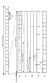
図3は、無線通信システム10において用いられる無線フレーム、サブフレーム及びスロットの構成例を示す。
Figure 3 shows an example configuration of radio frames, subframes, and slots used in the
図3に示すように、1スロットは、14シンボルで構成され、SCSが大きく(広く)なる程、シンボル期間(及びスロット期間)は短くなる。SCSは、図3に示す間隔(周波数)に限定されない。例えば、480kHz、960kHzなどが用いられてもよい。As shown in Figure 3, one slot consists of 14 symbols, and the larger (wider) the SCS, the shorter the symbol period (and slot period). The SCS is not limited to the interval (frequency) shown in Figure 3. For example, 480 kHz, 960 kHz, etc. may be used.
また、1スロットを構成するシンボル数は、必ずしも14シンボルでなくてもよい(例えば、28、56シンボル)。さらに、サブフレーム当たりのスロット数は、SCSによって異なっていてよい。 In addition, the number of symbols constituting one slot does not necessarily have to be 14 symbols (e.g., 28 or 56 symbols). Furthermore, the number of slots per subframe may differ depending on the SCS.
なお、図3に示す時間方向(t)は、時間領域、シンボル期間またはシンボル時間などと呼ばれてもよい。また、周波数方向は、周波数領域、リソースブロック、サブキャリア、BWP (Bandwidth Part)などと呼ばれてもよい。 The time direction (t) shown in FIG. 3 may be called the time domain, symbol period, or symbol time. The frequency direction may be called the frequency domain, resource block, subcarrier, BWP (Bandwidth Part), etc.
(2)無線通信システムの機能ブロック構成
次に、無線通信システム10の機能ブロック構成について説明する。具体的には、UE200の機能ブロック構成について説明する。
(2) Functional Block Configuration of Wireless Communication System Next, a functional block configuration of the
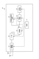
図4は、UE200の機能ブロック構成図である。図4に示すように、UE200は、無線信号送受信部210、アンプ部220、変復調部230、制御信号・参照信号処理部240、符号化/復号部250、データ送受信部260及び制御部270を備える。
Figure 4 is a functional block diagram of
無線信号送受信部210は、NRに従った無線信号を送受信する。無線信号送受信部210は、Massive MIMO、複数のCCを束ねて用いるCA、及びUEと2つのNG-RAN Nodeそれぞれとの間において同時に通信を行うDCなどに対応する。The radio signal transmission/
アンプ部220は、PA (Power Amplifier)/LNA (Low Noise Amplifier)などによって構成される。アンプ部220は、変復調部230から出力された信号を所定の電力レベルに増幅する。また、アンプ部220は、無線信号送受信部210から出力されたRF信号を増幅する。The
変復調部230は、所定の通信先(gNB100または他のgNB)毎に、データ変調/復調、送信電力設定及びリソースブロック割当などを実行する。変復調部230では、Cyclic Prefix-Orthogonal Frequency Division Multiplexing(CP-OFDM)/Discrete Fourier Transform - Spread(DFT-S-OFDM)が適用されてもよい。また、DFT-S-OFDMは、上りリンク(UL)だけでなく、下りリンク(DL)にも用いられてもよい。The
制御信号・参照信号処理部240は、UE200が送受信する各種の制御信号に関する処理、及びUE200が送受信する各種の参照信号に関する処理を実行する。 The control signal/reference
具体的には、制御信号・参照信号処理部240は、gNB100から所定の制御チャネルを介して送信される各種の制御信号、例えば、無線リソース制御レイヤ(RRC)の制御信号を受信する。また、制御信号・参照信号処理部240は、gNB100に向けて、所定の制御チャネルを介して各種の制御信号を送信する。 Specifically, the control signal/
制御信号・参照信号処理部240は、Demodulation Reference Signal(DMRS)、及びPhase Tracking Reference Signal (PTRS)などの参照信号(RS)を用いた処理を実行する。The control signal/reference
DMRSは、データ復調に用いるフェージングチャネルを推定するための端末個別の基地局~端末間において既知の参照信号(パイロット信号)である。PTRSは、高い周波数帯で課題となる位相雑音の推定を目的した端末個別の参照信号である。 DMRS is a known reference signal (pilot signal) between the base station and the terminal for each terminal, used to estimate the fading channel used for data demodulation. PTRS is a terminal-specific reference signal intended to estimate phase noise, which is an issue in high frequency bands.
なお、参照信号には、DMRS及びPTRS以外に、Channel State Information-Reference Signal(CSI-RS)、Sounding Reference Signal(SRS)、及び位置情報用のPositioning Reference Signal(PRS)が含まれてもよい。In addition to DMRS and PTRS, reference signals may also include Channel State Information-Reference Signal (CSI-RS), Sounding Reference Signal (SRS), and Positioning Reference Signal (PRS) for location information.
また、チャネルには、制御チャネルとデータチャネルとが含まれる。制御チャネルには、PDCCH(Physical Downlink Control Channel)、PUCCH(Physical Uplink Control Channel)、RACH(Random Access Channel)、Random Access Radio Network Temporary Identifier(RA-RNTI)を含むDownlink Control Information (DCI))、及びPhysical Broadcast Channel(PBCH)などが含まれる。 Channels include control channels and data channels. Control channels include PDCCH (Physical Downlink Control Channel), PUCCH (Physical Uplink Control Channel), RACH (Random Access Channel), Downlink Control Information (DCI) including Random Access Radio Network Temporary Identifier (RA-RNTI), and Physical Broadcast Channel (PBCH).
また、データチャネルには、PDSCH(Physical Downlink Shared Channel)、及びPUSCH(Physical Uplink Shared Channel)などが含まれる。データとは、データチャネルを介して送信されるデータを意味する。データチャネルは、共有チャネルと読み替えられてもよい。 Data channels include PDSCH (Physical Downlink Shared Channel) and PUSCH (Physical Uplink Shared Channel). Data refers to data transmitted via the data channel. The data channel may be read as a shared channel.
実施形態では、制御信号・参照信号処理部240は、異なる優先度を有する2以上の上りリンクチャネルを用いた上りリンク信号の送信を実行する。異なる優先度を有する2以上の上りリンクチャネルは、2以上のDCIに対応する上りリンクチャネルであってもよい。上りリンクチャネルは、物理上りリンク制御チャネル(PUCCH: Physical Uplink Control Channel)及び物理上りリンク共有チャネル(PUSCH: Physical Uplink Shared Channel)を含む。上りリンク信号は、上りリンク制御情報(UCI: Uplink Control Information)を含んでもよい。UCIは、1以上のTBに対する確認応答(HARQ-ACK)を含んでもよい。UCIは、リソースのスケジューリングを要求するSR(Scheduling Request)を含んでもよく、チャネルの状態を表すCSI(Channel State Information)を含んでもよい。UCIは、PUCCHを介して送信されてもよく、PUSCHを介して送信されてもよい。In an embodiment, the control signal/reference
符号化/復号部250は、所定の通信先(gNB100または他のgNB)毎に、データの分割/連結及びチャネルコーディング/復号などを実行する。The encoding/
具体的には、符号化/復号部250は、データ送受信部260から出力されたデータを所定のサイズに分割し、分割されたデータに対してチャネルコーディングを実行する。また、符号化/復号部250は、変復調部230から出力されたデータを復号し、復号したデータを連結する。Specifically, the encoding/
データ送受信部260は、Protocol Data Unit (PDU)ならびにService Data Unit (SDU)の送受信を実行する。具体的には、データ送受信部260は、複数のレイヤ(媒体アクセス制御レイヤ(MAC)、無線リンク制御レイヤ(RLC)、及びパケット・データ・コンバージェンス・プロトコル・レイヤ(PDCP)など)におけるPDU/SDUの組み立て/分解などを実行する。また、データ送受信部260は、ハイブリッドARQ(Hybrid automatic repeat request)に基づいて、データの誤り訂正及び再送制御を実行する。The data transmission/
制御部270は、UE200を構成する各機能ブロックを制御する。特に、実施形態では、制御部270は、2以上の上りリンクチャネルの多重に関する多重タイムライン条件が満たされる場合に、2以上の上りリンクチャネルの多重に関する多重制御を実行する。制御部270は、2以上の上りリンクチャネルの優先付けに関する優先付けタイムライン条件が満たされる場合に、2以上の上りリンクチャネルの優先付けに関する優先制御を実行する。制御部270は、多重タイムライン条件が満たされるか否かを判定した後に、優先付けタイムライン条件が満たされるかを判定する。以下においては、上りリンク信号の一例としてUCIを例示する。The
(3)タイムライン
以下において、タイムラインについて説明する。具体的には、UE200の処理時間に関する処理タイムライン、多重制御に関するタイムライン、優先制御に関するタイムラインについて説明する。
(3) Timelines The following describes timelines. Specifically, the following describes a processing timeline related to the processing time of the
(3.1)処理時間に関するタイムライン
第1に、PUCCHを介してUCIを送信するケースについて図5の上段を参照しながら説明する。図5の上段に示すように、UE200は、DCIを含むPDSCHの最後のシンボルとPUCCHの最初のシンボルとの間の時間がN1+d1,1シンボルを超えないケースを想定してはならない。言い換えると、PUCCHに関するUE200の処理時間に関する処理タイムライン条件は、PDSCHの最後のシンボルとPUCCHの最初のシンボルとの間の時間がN1+d1,1シンボル以上であることである。N1は、UE200のUE Capability及びSCSに応じて定められるパラメータであり、d1,1は、UE200のUE Capability及びPDSCHのMapping typeなどに応じて定められるパラメータである(3GPP TS38.214 V16.3.0 §5.3 ”UE PDSCH processing procedure time”)。
(3.1) Timeline for Processing Time First, a case of transmitting UCI via PUCCH will be described with reference to the upper part of Fig. 5. As shown in the upper part of Fig. 5,
第2に、PUSCHを介してUCIを送信するケースについて図5の下段を参照しながら説明する。図5の下段に示すように、UE200は、DCIを含むPDCCHの最後のシンボルとPUSCHの最初のシンボルとの間の時間がN2+d2,1シンボルを超えないケースを想定してはならない。言い換えると、PUSCHに関するUE200の処理時間に関する処理タイムライン条件は、PDCCHの最後のシンボルとPUSCHの最初のシンボルとの間の時間がN2+d2,1シンボル以上であることである。N2は、UE200のUE Capability及びSCSに応じて定められるパラメータであり、d2,1は、PUSCHの最初のシンボルがDMRSのみを含むか否かなどに応じて定められるパラメータである(3GPP TS38.214 V16.3.0 §6.4 ” UE PUSCH preparation procedure time”)。
Secondly, a case where UCI is transmitted via PUSCH will be described with reference to the lower part of FIG. 5. As shown in the lower part of FIG. 5,
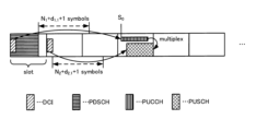
(3.2)多重制御に関するタイムライン
以下において、同一スロットにおいてPUCCH及びPUSCHの多重制御について図6を参照しながら説明する。図6に示すように、UE200は、DCIを含むPDSCHの最後のシンボルと最先の上りリンクチャネル(PUCCH)の最初のシンボルとの間の時間がN1+d1,1+1シンボルを超えない場合に、2以上の上りリンクチャネルの多重を想定してはならない。最先の上りリンクチャネルは、同一スロットで多重される2以上の上りリンクチャネルうち、最先の上りリンクチャネルを意味する。最先の上りリンクチャネルの最初のシンボルは、最先の上りリンクチャネルの開始位置(第1開始位置)と呼称されてもよい。最先の上りリンクチャネルの最初のシンボルは、S0と呼称されてもよい。言い換えると、2以上の上りリンクチャネルの多重に関する多重タイムライン条件は、PDSCHの最後のシンボルと最先の上りリンクチャネルの開始位置(S0)との間の時間がN1+d1,1+1シンボル以上であることである。N1+d1,1+1は、多重タイムライン条件を定義する時間閾値(第1時間閾値)の一例である。
(3.2) Timeline for Multiplexing Control In the following, multiplexing control of PUCCH and PUSCH in the same slot will be described with reference to FIG. 6. As shown in FIG. 6,
また、UE200は、DCIを含むPDCCHの最後のシンボルと最先の上りリンクチャネルの開始位置(S0)との間の時間がN2+d2,1+1シンボルを超えない場合に、2以上の上りリンクチャネルの多重を想定してはならない。言い換えると、2以上の上りリンクチャネルの多重タイムライン条件は、PDCCHの最後のシンボルと最先の上りリンクチャネルの開始位置(S0)との間の時間がN2+d2,1+1シンボル以上であることである。N2+d2,1+1は、多重タイムライン条件を定義する時間閾値(第1時間閾値)の一例である。
Furthermore, the
UE200は、多重タイムライン条件が満たされる場合に、PUCCHをPUSCHに多重する。UE200は、多重タイムライン条件が満たされないケースを想定していないが、多重タイムライン条件が満たされない場合に、PUCCH及びPUSCHの双方の送信を実行しなくてもよい。 UE200 multiplexes PUCCH onto PUSCH when the multiplexing timeline condition is satisfied. UE200 does not assume a case where the multiplexing timeline condition is not satisfied, but does not need to transmit both PUCCH and PUSCH when the multiplexing timeline condition is not satisfied.
(3.3)優先制御に関するタイムライン
以下において、同一スロットにおいてPUCCH及びPUSCHの優先制御について図7を参照しながら説明する。
(3.3) Timeline for Priority Control Priority control of PUCCH and PUSCH in the same slot will be described below with reference to FIG.
図7の上段に示すように、UE200は、DCIを含むPDCCHの最後のシンボルと最先の上りリンクチャネル(PUCCH)の最初のシンボル(上述したS0)との間の時間がN2+d2,1+d1シンボルを超えない場合に、2以上の上りリンクチャネルの優先付けを想定してはならない。言い換えると、2以上の上りリンクチャネルの優先付けに関する優先付けタイミング条件は、PDCCHの最後のシンボルと最先の上りリンクチャネルの開始位置(S0)との間の時間がN2+d2,1+d1シンボル以上であることである。
As shown in the upper part of Fig. 7, the
例えば、UE200は、優先付けタイムライン条件が満たされる場合に、PUCCH(LP; Low Priority)を介してUCIを送信せずに、PUSCH(HP; High Priority)を介してUCIを送信する。UE200は、優先付けタイムライン条件が満たされないケースを想定していないが、優先付けタイムライン条件が満たされない場合に、PUCCH及びPUSCHの双方の送信を実行しなくてもよい。For example, when the prioritization timeline condition is satisfied, UE200 transmits UCI via PUSCH (HP; High Priority) without transmitting UCI via PUCCH (LP; Low Priority). UE200 does not assume a case where the prioritization timeline condition is not satisfied, but may not transmit both PUCCH and PUSCH when the prioritization timeline condition is not satisfied.
同様に、図7の下段に示すように、UE200は、DCIを含むPDCCHの最後のシンボルと最先の上りリンクチャネル(PUSCH)の最初のシンボル(上述したS0)との間の時間がN2+d2,1+d1シンボルを超えない場合に、2以上の上りリンクチャネルの優先付けを想定してはならない。言い換えると、2以上の上りリンクチャネルの優先付けに関する優先付けタイミング条件は、PDCCHの最後のシンボルと最先の上りリンクチャネルの開始位置(S0)との間の時間がN2+d2,1+d1シンボル以上であることである。
Similarly, as shown in the lower part of Fig. 7,
例えば、UE200は、優先付けタイムライン条件が満たされる場合に、PUSCH(LP; Low Priority)を介してUCIを送信せずに、PUCCH(HP; High Priority)を介してUCIを送信する。UE200は、優先付けタイムライン条件が満たされないケースを想定していないが、優先付けタイムライン条件が満たされない場合に、PUCCH及びPUSCHの双方の送信を実行しなくてもよい。For example, when the prioritization timeline condition is satisfied, UE200 transmits UCI via PUCCH (HP; High Priority) without transmitting UCI via PUSCH (LP; Low Priority). UE200 does not assume a case where the prioritization timeline condition is not satisfied, but may not transmit both PUCCH and PUSCH when the prioritization timeline condition is not satisfied.
(4)課題
発明者等は、鋭意検討の結果、異なる優先度を有する上りリンクチャネルに関する多重制御及び優先制御を実行する場合に、上述したタイムラインを想定すると、以下に示す課題が生じる可能性を見出した。
(4) Problems As a result of careful consideration, the inventors have found that when multiplex control and priority control are performed for uplink channels having different priorities, assuming the above-mentioned timeline, the following problems may arise.
第1に、Case 1について説明する。図8の上段に示すように、1つ目のPUCCH(LP)に着目した場合に、処理タイムライン条件は、DCIを含むPDSCHの最後のシンボルと最先の上りリンクチャネル(ここでは、PUCCH(LP))の開始位置(S0)との間の時間がN1+d1,1シンボル(#1)以上であることであり、優先付けタイムライン条件は、DCIを含むPDCCHの最後のシンボルと最先の上りリンクチャネル(ここでは、PUCCH(LP))の開始位置(S0)との間の時間がN2+d2,1+d1シンボル以上であることである。しかしながら、処理タイムライン条件が満たされているか否かを判定するための時間の起点がPDSCHの最後のシンボルであるのに対して、優先付けタイムライン条件が満たされているか否かを判定するための時間の起点がPDCCHの最後のシンボルである。従って、優先付けタイムライン条件(N2+d2,1+d1シンボル)が満たされているにもかかわらず、1つ目のPUCCH(LP)の処理タイムライン条件(N1+d1,1シンボル(#1))が満たされないことが考えられる。上述したように、処理タイムライン条件が満たされないケースが想定されていないため、Case 1においてUE200の動作が不明瞭である。
First,
第2に、Case 2について説明する。図8の下段に示すように、1つ目のPUCCH(LP)に着目した場合に、処理タイムライン条件は、DCIを含むPDSCHの最後のシンボルと最先の上りリンクチャネル(ここでは、PUCCH(LP))の開始位置(S0)との間の時間がN1+d1,1シンボル(#1)以上であることであり、優先付けタイムライン条件は、DCIを含むPDCCHの最後のシンボルと最先の上りリンクチャネル(ここでは、PUCCH(LP))の開始位置(S0)との間の時間がN2+d2,1+d1シンボル以上であることである。一方で、2つ目のPUCCH(HP)に着目した場合に、処理タイムライン条件は、DCIを含むPDSCHの最後のシンボルと最先の上りリンクチャネル(ここでは、PUCCH(LP))の開始位置(S0)との間の時間がN1+d1,1シンボル(#2)以上であることである。このようなケースにおいては、優先付けタイムライン条件(N2+d2,1+d1シンボル)及び1つ目のPUCCH(LP)の処理タイムライン条件(N1+d1,1シンボル(#1))が満たされているにもかかわらず、2つ目のPUCCH(HP)の処理タイムライン条件(N1+d1,1シンボル(#2))が満たされないことが考えられる。上述したように、処理タイムライン条件が満たされないケースが想定されていないため、Case 2においてUE200の動作が不明瞭である。
Secondly,
第3に、Case 3について説明する。図9の上段に示すように、優先付けタイムライン条件(N2+d2,1+d1シンボル)が満たされているにもかかわらず、1つ目のPUCCH(LP)の多重タイムライン条件(N1+d1,1+1シンボル(#1))が満たされないことが考えられる。同様に、優先付けタイムライン条件(N2+d2,1+d1シンボル)が満たされているにもかかわらず、2つ目のPUSCH(HP)の多重タイムライン条件(N2+d2,1+1シンボル(#2))が満たされないことも考えられる。上述したように、多重タイムライン条件が満たされないケースが想定されていないため、Case 3においてUE200の動作が不明瞭である。
Thirdly,
第4に、Case 4について説明する。図9の上段に示すように、優先付けタイムライン条件(N2+d2,1+d1シンボル)及び1つ目のPUSCH(LP)の多重タイムライン条件(N2+d2,1+1シンボル(#1))が満たされているにもかかわらず、2つ目のPUCCH(HP)の多重タイムライン条件(N1+d1,1+1シンボル(#2))が満たされないことが考えられる。上述したように、多重タイムライン条件が満たされないケースが想定されていないため、Case 4においてUE200の動作が不明瞭である。
Fourthly,
(5)制御例
上述したCase 1~Case 4で説明したように、優先付けタイムライン条件が満たされても、処理タイムライン条件及び多重タイムライン条件が満たされないケースが考えられる。このような着眼点から、実施形態では、UE200(制御部270)は以下の動作を実行する。
(5) Control Example As described above in
具体的には、制御部270は、多重タイムライン条件が満たされるか否かを判定した後に、優先付けタイムライン条件が満たされるかを判定する。すなわち、制御部270は、多重タイムラインが満たされた場合に、2以上の上りリンクチャネルの多重制御を実行する。制御部270は、多重タイムラインが満たされずに、優先付けタイムライン条件が満たされる場合に、2以上の上りリンクチャネルの優先制御を実行する。このような前提下において、以下のような仕組みが導入されてもよい。
Specifically, the
(5.1)制御例1
制御例1では、多重タイムライン条件を定義する時間閾値として新たなパラメータが導入される。具体的には、多重タイムライン条件は、2以上の上りリンクチャネルの優先度に基づかない多重制御で用いる第1多重タイムライン条件と、2以上の上りリンクチャネルの優先度に基づいた多重制御で用いる第2多重タイムライン条件と、を含む。第2多重タイムライン条件を定義する第2時間閾値は、第1多重タイムライン条件を定義する第1時間閾値よりも短い。ここで、第1時間閾値は、既存のパラメータであり、第2時間閾値は、新たなパラメータの一例である。
(5.1) Control example 1
In control example 1, a new parameter is introduced as a time threshold that defines a multiplex timeline condition. Specifically, the multiplex timeline condition includes a first multiplex timeline condition used in multiplex control not based on the priority of two or more uplink channels, and a second multiplex timeline condition used in multiplex control based on the priority of two or more uplink channels. The second time threshold that defines the second multiplex timeline condition is shorter than the first time threshold that defines the first multiplex timeline condition. Here, the first time threshold is an existing parameter, and the second time threshold is an example of a new parameter.
例えば、図10の制御例1-1に示すように、2つ目のPUCCH(HP)に関する多重タイムライン条件として第2タイムライン条件が導入されてもよい。例えば、第2多重タイムライン条件を定義する時間閾値としてPnewが導入される。Pnewは、第1時間閾値(N1+d1,1+1)よりも短い時間である。PnewはN1+d1,1であってもよい。Pnewは、処理タイムライン条件を定義する時間閾値以上であってもよい。特に限定されるものではないが、1つ目のPUCCH(LP)については、第1時間閾値(N1+d1,1+1)が適用されてもよい。或いは、1つ目のPUCCH(LP)についても、第2時間閾値(Pnew)が適用されてもよい。 For example, as shown in control example 1-1 of FIG. 10, a second timeline condition may be introduced as a multiplex timeline condition for the second PUCCH (HP). For example, P new is introduced as a time threshold that defines the second multiplex timeline condition. P new is a time shorter than the first time threshold (N 1 +d 1,1 +1). P new may be N 1 +d 1,1 . P new may be equal to or greater than the time threshold that defines the processing timeline condition. Although not particularly limited, the first time threshold (N 1 +d 1,1 +1) may be applied to the first PUCCH (LP). Alternatively, the second time threshold (P new ) may also be applied to the first PUCCH (LP).
同様に、図10の制御例1-2に示すように、2つ目のPUSCHに関する多重タイムライン条件として第2タイムライン条件が導入されてもよい。例えば、第2多重タイムライン条件を定義する時間閾値としてQnewが導入される。Qnewは、第1時間閾値(N2+d2,1+1)よりも短い時間である。QnewはN2+d2,1であってもよい。Qnewは、処理タイムライン条件を定義する時間閾値以上であってもよい。特に限定されるものではないが、1つ目のPUCCH(LP)については、第1時間閾値(N1+d1,1+1)が適用されてもよい。 Similarly, as shown in control example 1-2 of FIG. 10, a second timeline condition may be introduced as a multiplex timeline condition for the second PUSCH. For example, Q new is introduced as a time threshold that defines the second multiplex timeline condition. Q new is a time shorter than the first time threshold (N 2 +d 2,1 +1). Q new may be N 2 +d 2,1 . Q new may be equal to or greater than the time threshold that defines the processing timeline condition. Although not particularly limited, the first time threshold (N 1 +d 1,1 +1) may be applied to the first PUCCH (LP).
(5.2)制御例2
制御例2では、多重タイムライン条件で用いる上りリンクチャネルの開始位置について、新たな解釈又は新たなパラメータが導入される。具体的には、多重タイムライン条件は、上りリンク信号の優先度に基づかない多重制御で用いる第1多重タイムライン条件と、上りリンク信号の優先度に基づいた多重制御で用いる第2多重タイムライン条件と、を含む。第1多重タイムライン条件で用いる上りリンクチャネルの第1開始位置は、多重制御で多重される2以上の上りリンクチャネルのうち、最先の上りリンクチャネルの開始位置(上述したS0)である。一方で、第2多重タイムライン条件で用いる上りリンクチャネルの第2開始位置は、多重制御で多重される2以上の上りリンクチャネルのうち、多重制御で用いるリソースを有する上りリンクチャネルの開始位置(Snew)である。第2開始位置は、新たな解釈の一例であると考えてよく、新たなパラメータの一例であると考えてもよい。ここで、第2多重タイムライン条件は、PDCCHの最終シンボルからSnewまでの時間閾値(第3時間閾値と呼称してもよい)がN1+d1,1+xまたはN2+d2,1+yより長い時間であると定義されてもよい。
(5.2) Control Example 2
In the control example 2, a new interpretation or a new parameter is introduced for the start position of the uplink channel used in the multiplex timeline condition. Specifically, the multiplex timeline condition includes a first multiplex timeline condition used in the multiplex control not based on the priority of the uplink signal, and a second multiplex timeline condition used in the multiplex control based on the priority of the uplink signal. The first start position of the uplink channel used in the first multiplex timeline condition is the start position (S 0 described above) of the earliest uplink channel among two or more uplink channels multiplexed in the multiplex control. On the other hand, the second start position of the uplink channel used in the second multiplex timeline condition is the start position (S new ) of the uplink channel having the resource used in the multiplex control among two or more uplink channels multiplexed in the multiplex control. The second start position may be considered as an example of a new interpretation or an example of a new parameter. Here, the second multiplexing timeline condition may be defined as a time threshold (which may be referred to as a third time threshold) from the last symbol of the PDCCH to Snew being longer than N1 + d1,1 +x or N2 + d2,1 +y.
多重制御で用いるリソースを有する上りリンクチャネルは、第1上りリンクチャネルを第2上りリンクチャネルに多重するケースにおいて、第2上りリンクチャネルを意味する。第2上りリンクチャネルの優先度は、第1上りリンクチャネルの優先度よりも高くてもよい。The uplink channel having resources used in the multiplexing control means the second uplink channel in the case where the first uplink channel is multiplexed into the second uplink channel. The priority of the second uplink channel may be higher than the priority of the first uplink channel.
例えば、図11の制御例2-1に示すように、2つ目のPUCCH(HP)に関する多重タイムライン条件として第2タイムライン条件が導入されてもよい。第2多重タイムライン条件で用いる上りリンクチャネルの開始位置は、多重制御で用いるリソースを有するPUCCH(HP)の開始位置(Snew)である。ここでは、PUCCH(LP)がPUCCH(HP)に多重されるケースが例示されている。 For example, as shown in control example 2-1 of Fig. 11, a second timeline condition may be introduced as a multiplexing timeline condition for a second PUCCH (HP). The start position of the uplink channel used in the second multiplexing timeline condition is the start position (S new ) of the PUCCH (HP) having the resource used in the multiplexing control. Here, a case in which the PUCCH (LP) is multiplexed into the PUCCH (HP) is illustrated.
同様に、図11の制御例2-2に示すように、2つ目のPUSCH(HP)に関する多重タイムライン条件として第2タイムライン条件が導入されてもよい。第2多重タイムライン条件で用いる上りリンクチャネルの開始位置は、多重制御で用いるリソースを有するPUSCH(HP)の開始位置(Snew)である。ここでは、PUCCH(LP)がPUSCH(HP)に多重されるケースが例示されている。 Similarly, as shown in control example 2-2 of FIG. 11, a second timeline condition may be introduced as a multiplexing timeline condition for a second PUSCH (HP). The start position of the uplink channel used in the second multiplexing timeline condition is the start position (S new ) of the PUSCH (HP) having the resource used in the multiplexing control. Here, a case in which the PUCCH (LP) is multiplexed into the PUSCH (HP) is illustrated.
同様に、図11の制御例2-3に示すように、2つ目のPUCCH(HP)に関する多重タイムライン条件として第2タイムライン条件が導入されてもよい。第2多重タイムライン条件で用いる上りリンクチャネルの開始位置は、多重制御で用いるリソースを有するPUCCH(HP)の開始位置(Snew)である。ここでは、PUSCH(LP)がPUCCH(HP)に多重されるケースが例示されている。 Similarly, as shown in control example 2-3 of Fig. 11, a second timeline condition may be introduced as a multiplexing timeline condition for a second PUCCH (HP). The start position of the uplink channel used in the second multiplexing timeline condition is the start position (S new ) of the PUCCH (HP) having the resource used in the multiplexing control. Here, a case in which the PUSCH (LP) is multiplexed into the PUCCH (HP) is illustrated.
なお、優先付けタイムライン条件については、既存のパラメータ(図7を参照)が用いられてもよい。また、制御例2及び制御例3は組み合わされてもよい。 Note that existing parameters (see FIG. 7) may be used for the prioritization timeline conditions. Control example 2 and control example 3 may also be combined.
(5.3)制御例3
制御例3では、異なる優先度を有する2以上の上りリンクチャネルの多重について制約が設けられる。具体的には、制御部270は、2以上の上りリンクチャネルの開始位置が揃っている場合に、多重制御を実行してもよい。制御部270は、2以上の上りリンクチャネルの開始位置が揃っていない場合に、多重制御を実行せずに優先制御を実行してもよい。
(5.3) Control Example 3
In control example 3, a restriction is imposed on multiplexing of two or more uplink channels having different priorities. Specifically, the
以下においては、図12に示すように、PUCCH(LP)がスロット単位で送信され、PUCCH(HP)がサブスロット単位で送信されるケースについて考える。In the following, we consider the case where PUCCH (LP) is transmitted in slot units and PUCCH (HP) is transmitted in subslot units, as shown in Figure 12.
例えば、図12の制御例3-1に示すように、制御部270は、PUCCH(HP)#1の開始位置を含むサブスロットの開始位置がPUCCH(LP)#1の開始位置を含むスロットの開始位置と一致する場合に、PUCCH(LP)#1をPUCCH(HP)#1に多重してもよい。言い換えると、PUCCH(LP)#1及びPUCCH(HP)#1が同一境界において衝突する場合に、PUCCH(LP)#1及びPUCCH(HP)#1の多重制御が実行されてもよい。なお、2以上の上りリンクチャネルの開始位置を含むスロット又はサブスロットの開始位置が一致する(すなわち、2以上の上りリンクチャネルが同一境界で衝突する)ケースは、2以上の上りリンクチャネルの開始位置が揃っていると表現されてもよい。For example, as shown in control example 3-1 of FIG. 12, the
一方で、図12の制御例3-2に示すように、制御部270は、PUCCH(HP)#2の開始位置を含むサブスロットの開始位置がPUCCH(LP)#1の開始位置を含むスロットの開始位置と一致しない場合に、PUCCH(LP)#1をPUCCH(HP)#2に多重せずに、PUCCH(LP)#1及びPUCCH(HP)#2の優先制御を実行してもよい。言い換えると、PUCCH(LP)#1及びPUCCH(HP)#2が同一境界において衝突しない場合に、PUCCH(LP)#1及びPUCCH(HP)#2の優先制御が実行されてもよい。例えば、制御部270は、PUCCH(LP)#1を送信せずに、PUCCH(HP)#2を送信してもよい。なお、2以上の上りリンクチャネルの開始位置を含むスロット又はサブスロットの開始位置が一致しない(すなわち、2以上の上りリンクチャネルが同一境界で衝突しない)ケースは、2以上の上りリンクチャネルの開始位置が揃っていないと表現されてもよい。On the other hand, as shown in control example 3-2 of FIG. 12, when the start position of a subslot including the start position of PUCCH (HP) #2 does not match the start position of a slot including the start position of PUCCH (LP) #1, the
(6)動作例
以下において、実施形態の動作例について説明する。以下においては、異なる優先度を有する2以上の上りリンクチャネルの多重制御及び優先制御がUE200に設定されるケースについて例示する。
(6) Operation Example An operation example of the embodiment will be described below. In the following, a case where multiplexing control and priority control of two or more uplink channels having different priorities are set in the
図13に示すように、ステップS10において、UE200は、UE Capabilityを含むメッセージをNG-RAN20に送信する。UE Capabilityは、異なる優先度を有する2以上の上りリンクチャネルの多重制御をサポートしているか否かを示す情報要素を含んでもよい。UE Capabilityは、異なる優先度を有する2以上の上りリンクチャネルの優先制御をサポートしているか否かを示す情報要素を含んでもよい。13, in step S10,
ステップS11において、UE100は、複数のCCに関連するPUCCH-Config.を含むRRCメッセージをNG-RAN20から受信する。PUCCH-Config.は、異なる優先度を有する2以上の上りリンクチャネルの多重制御を設定するか否かを示す情報要素を含んでもよい。PUCCH-Config.は、異なる優先度を有する2以上の上りリンクチャネルの優先制御を設定するか否かを示す情報要素を含んでもよい。In step S11,
ステップS12において、UE200は、PDCCHを介して1以上のDCIをNG-RAN20から受信する。NG-RAN20は、ステップS10で受信するUE Capabilityに基づいてDCIを送信してもよい。言い換えると、DCIは、UE Capabilityを考慮した上りリンクリソースを指定する情報要素(例えば、Frequency domain resource assignment、Time domain resource assignment)を含んでもよい。In step S12,
ステップS13において、UE200は、多重タイムライン条件が満たされるか否かを判定した後に、優先付けタイムライン条件が満たされるかを判定する。UE200は、多重タイムライン条件が満たされる場合に、異なる優先度を有する2以上の上りリンクチャネルを同一スロットにおいて多重する。UE200は、優先付けタイムライン条件が満たされる場合に、異なる優先度を有する2以上の上りリンクチャネルを同一スロットにおいて優先付けする。In step S13, UE200 determines whether the multiplexing timeline condition is satisfied, and then determines whether the prioritization timeline condition is satisfied. If the multiplexing timeline condition is satisfied, UE200 multiplexes two or more uplink channels having different priorities in the same slot. If the prioritization timeline condition is satisfied, UE200 prioritizes two or more uplink channels having different priorities in the same slot.
(7)作用・効果
実施形態では、UE200は、多重タイムライン条件が満たされるか否かを判定した後に、優先付けタイムライン条件が満たされるかを判定する。このような構成によれば、優先付けタイムライン条件が満たされているが、多重タイムライン条件が満たされないケース(図9に示すCase 3及びCase 4)において、UE200の動作が不明瞭になる事態を回避することができ、多重及び優先付けに関する適切な制御を実行することができる。
(7) Function and Effect In the embodiment, the
実施形態では、多重タイムライン条件を定義する時間閾値として新たなパラメータ(第2時間閾値)が導入され、第2時間閾値は第1時間閾値よりも短い。このような構成によれば、異なる優先度を有する2以上の上りリンクチャネルの多重に要求される遅延が減少する。In the embodiment, a new parameter (second time threshold) is introduced as a time threshold that defines the multiplexing timeline condition, and the second time threshold is shorter than the first time threshold. With such a configuration, the delay required for multiplexing two or more uplink channels with different priorities is reduced.
実施形態では、多重タイムライン条件で用いる上りリンクチャネルの開始位置について、新たな解釈又は新たなパラメータ(第2開始位置)が導入される。第2開始位置は、多重制御で用いるリソースを有する上りリンクチャネルの開始位置である。このような構成によれば、多重に伴う処理に影響を与えることなく、多重制御を適切に実行することができる。 In an embodiment, a new interpretation or a new parameter (second start position) is introduced for the start position of the uplink channel used in the multiplexing timeline condition. The second start position is the start position of the uplink channel having resources used in the multiplexing control. With such a configuration, the multiplexing control can be appropriately executed without affecting the processing associated with the multiplexing.
[その他の実施形態]
以上、実施形態に沿って本発明の内容を説明したが、本発明はこれらの記載に限定されるものではなく、種々の変形及び改良が可能であることは、当業者には自明である。
[Other embodiments]
The present invention has been described above in accordance with the embodiments, but the present invention is not limited to these descriptions, and it will be obvious to those skilled in the art that various modifications and improvements are possible.
上述した開示では、上りリンク信号の一例としてUCIを例示した。しかしながら、上述した開示はこれに限定されるものではない。上りリンク信号は、データ信号を含んでもよい。すなわち、上述した開示は、異なる優先度を有する2以上の上りリンクチャネルの多重及び優先付けに提供されればよい。In the above disclosure, UCI is given as an example of an uplink signal. However, the above disclosure is not limited thereto. The uplink signal may include a data signal. That is, the above disclosure may be provided for multiplexing and prioritizing two or more uplink channels having different priorities.
上述した開示では、課題としてCase 1~Case 4について例示したが、上述した開示はこれに限定されるものではない。上述した開示は、優先タイムライン条件が満たされるにもかかわらずに、多重タイムライン条件が満たされないケースに適用可能である。
In the above disclosure,
上述した開示では、多重タイムライン条件について説明したが、上述した開示はこれに限定されるものではない。上述した開示は、優先タイムライン条件が満たされるにもかかわらずに、処理タイムライン条件が満たされないケースに適用可能である。このようなケースにおいて、多重タイムラインに関する記載を処理タイムラインに関する記載に置き換えればよい。例えば、UE200は、処理タイムライン条件が満たされるか否かを判定した後に、優先付けタイムライン条件が満たされるかを判定してもよい。 In the above disclosure, multiple timeline conditions have been described, but the above disclosure is not limited thereto. The above disclosure is applicable to cases where the processing timeline conditions are not satisfied even though the priority timeline conditions are satisfied. In such cases, the description regarding the multiple timelines may be replaced with a description regarding the processing timeline. For example, UE200 may determine whether the priority timeline conditions are satisfied after determining whether the processing timeline conditions are satisfied.
上述した開示では特に触れていないが、多重制御及び優先制御は以下のように実行されてもよい。例えば、HARQ-ACKに関するPUCCHの優先度は、SRに関するPUCCHの優先度よりも高くてもよい。このようなケースにおいて、SRに関するPUCCHはHARQ-ACKに関するPUCCHに多重されてもよい。このような多重ができない場合には、SRに関するPUCCHが送信されずに、HARQ-ACKに関するPUCCHが送信されてもよい。URLLC(Ultra Reliable and Low Latency Communications)に関するPUCCHの優先度は、eMBB(enhanced Mobile BroadBand)に関するPUSCHの優先度よりも高くてもよい。このようなケースにおいて、eMBBに関するPUSCHを送信せずに、URLLCに関するPUCCHを送信してもよい。Although not specifically mentioned in the above disclosure, multiplexing control and priority control may be performed as follows. For example, the priority of the PUCCH for HARQ-ACK may be higher than the priority of the PUCCH for SR. In such a case, the PUCCH for SR may be multiplexed with the PUCCH for HARQ-ACK. If such multiplexing is not possible, the PUCCH for SR may not be transmitted and the PUCCH for HARQ-ACK may be transmitted. The priority of the PUCCH for URLLC (Ultra Reliable and Low Latency Communications) may be higher than the priority of the PUSCH for eMBB (enhanced Mobile BroadBand). In such a case, the PUCCH for URLLC may be transmitted without transmitting the PUSCH for eMBB.
上述した開示では、UCIについて主として説明したが、上述した開示はこれに限定されるものではない。UCIは、HARQ-ACKと読み替えられてもよく、SRと読み替えられてもよく、CSIと読み替えられてもよい。複数のCCを用いて送信可能なUCIは、HARQ-ACK、SR及びCSIの中から選択されたいずれかのパラメータであってもよい。 In the above disclosure, UCI has been mainly described, but the above disclosure is not limited thereto. UCI may be read as HARQ-ACK, SR, or CSI. UCI that can be transmitted using multiple CCs may be any parameter selected from HARQ-ACK, SR, and CSI.
上述した実施形態の説明に用いたブロック構成図(図4)は、機能単位のブロックを示している。これらの機能ブロック(構成部)は、ハードウェア及びソフトウェアの少なくとも一方の任意の組み合わせによって実現される。また、各機能ブロックの実現方法は特に限定されない。すなわち、各機能ブロックは、物理的又は論理的に結合した1つの装置を用いて実現されてもよいし、物理的又は論理的に分離した2つ以上の装置を直接的又は間接的に(例えば、有線、無線などを用いて)接続し、これら複数の装置を用いて実現されてもよい。機能ブロックは、上記1つの装置又は上記複数の装置にソフトウェアを組み合わせて実現されてもよい。The block diagram (Figure 4) used to explain the above-mentioned embodiment shows functional blocks. These functional blocks (components) are realized by any combination of at least one of hardware and software. Furthermore, the method of realizing each functional block is not particularly limited. That is, each functional block may be realized using one device that is physically or logically coupled, or may be realized using two or more devices that are physically or logically separated and directly or indirectly connected (e.g., using wires, wirelessly, etc.). The functional block may be realized by combining software with the one device or the multiple devices.
機能には、判断、決定、判定、計算、算出、処理、導出、調査、探索、確認、受信、送信、出力、アクセス、解決、選択、選定、確立、比較、想定、期待、見做し、報知(broadcasting)、通知(notifying)、通信(communicating)、転送(forwarding)、構成(configuring)、再構成(reconfiguring)、割り当て(allocating、mapping)、割り振り(assigning)などがあるが、これらに限られない。例えば、送信を機能させる機能ブロック(構成部)は、送信部(transmitting unit)や送信機(transmitter)と呼ばれる。何れも、上述したとおり、実現方法は特に限定されない。 Functions include, but are not limited to, judgement, determination, judgment, calculation, computation, processing, derivation, investigation, search, confirmation, reception, transmission, output, access, resolution, selection, election, establishment, comparison, assumption, expectation, regard, broadcasting, notifying, communicating, forwarding, configuring, reconfiguring, allocating, mapping, and assignment. For example, a functional block (component) that performs the transmission function is called a transmitting unit or transmitter. As mentioned above, there are no particular limitations on the method of realization for each.
さらに、上述したUE200(当該装置)は、本開示の無線通信方法の処理を行うコンピュータとして機能してもよい。図14は、当該装置のハードウェア構成の一例を示す図である。図14に示すように、当該装置は、プロセッサ1001、メモリ1002、ストレージ1003、通信装置1004、入力装置1005、出力装置1006及びバス1007などを含むコンピュータ装置として構成されてもよい。Furthermore, the above-mentioned UE200 (the device) may function as a computer that performs processing of the wireless communication method of the present disclosure. FIG. 14 is a diagram showing an example of the hardware configuration of the device. As shown in FIG. 14, the device may be configured as a computer device including a
なお、以下の説明では、「装置」という文言は、回路、デバイス、ユニットなどに読み替えることができる。当該装置のハードウェア構成は、図に示した各装置を1つ又は複数含むように構成されてもよいし、一部の装置を含まずに構成されてもよい。In the following description, the term "apparatus" may be interpreted as a circuit, device, unit, etc. The hardware configuration of the apparatus may be configured to include one or more of the apparatuses shown in the figure, or may be configured to exclude some of the apparatuses.
当該装置の各機能ブロック(図4参照)は、当該コンピュータ装置の何れかのハードウェア要素、又は当該ハードウェア要素の組み合わせによって実現される。Each functional block of the device (see Figure 4) is realized by any hardware element of the computer device, or a combination of such hardware elements.
また、当該装置における各機能は、プロセッサ1001、メモリ1002などのハードウェア上に所定のソフトウェア(プログラム)を読み込ませることによって、プロセッサ1001が演算を行い、通信装置1004による通信を制御したり、メモリ1002及びストレージ1003におけるデータの読み出し及び書き込みの少なくとも一方を制御したりすることによって実現される。
In addition, each function of the device is realized by loading a specified software (program) onto hardware such as the
プロセッサ1001は、例えば、オペレーティングシステムを動作させてコンピュータ全体を制御する。プロセッサ1001は、周辺装置とのインタフェース、制御装置、演算装置、レジスタなどを含む中央処理装置(CPU)によって構成されてもよい。The
また、プロセッサ1001は、プログラム(プログラムコード)、ソフトウェアモジュール、データなどを、ストレージ1003及び通信装置1004の少なくとも一方からメモリ1002に読み出し、これらに従って各種の処理を実行する。プログラムとしては、上述の実施の形態において説明した動作の少なくとも一部をコンピュータに実行させるプログラムが用いられる。さらに、上述の各種処理は、1つのプロセッサ1001によって実行されてもよいし、2つ以上のプロセッサ1001により同時又は逐次に実行されてもよい。プロセッサ1001は、1以上のチップによって実装されてもよい。なお、プログラムは、電気通信回線を介してネットワークから送信されてもよい。
Furthermore, the
メモリ1002は、コンピュータ読み取り可能な記録媒体であり、例えば、Read Only Memory(ROM)、Erasable Programmable ROM(EPROM)、Electrically Erasable Programmable ROM(EEPROM)、Random Access Memory(RAM)などの少なくとも1つによって構成されてもよい。メモリ1002は、レジスタ、キャッシュ、メインメモリ(主記憶装置)などと呼ばれてもよい。メモリ1002は、本開示の一実施形態に係る方法を実行可能なプログラム(プログラムコード)、ソフトウェアモジュールなどを保存することができる。The
ストレージ1003は、コンピュータ読み取り可能な記録媒体であり、例えば、Compact Disc ROM(CD-ROM)などの光ディスク、ハードディスクドライブ、フレキシブルディスク、光磁気ディスク(例えば、コンパクトディスク、デジタル多用途ディスク、Blu-ray(登録商標)ディスク)、スマートカード、フラッシュメモリ(例えば、カード、スティック、キードライブ)、フロッピー(登録商標)ディスク、磁気ストリップなどの少なくとも1つによって構成されてもよい。ストレージ1003は、補助記憶装置と呼ばれてもよい。上述の記録媒体は、例えば、メモリ1002及びストレージ1003の少なくとも一方を含むデータベース、サーバその他の適切な媒体であってもよい。
通信装置1004は、有線ネットワーク及び無線ネットワークの少なくとも一方を介してコンピュータ間の通信を行うためのハードウェア(送受信デバイス)であり、例えばネットワークデバイス、ネットワークコントローラ、ネットワークカード、通信モジュールなどともいう。
The
通信装置1004は、例えば周波数分割複信(Frequency Division Duplex:FDD)及び時分割複信(Time Division Duplex:TDD)の少なくとも一方を実現するために、高周波スイッチ、デュプレクサ、フィルタ、周波数シンセサイザなどを含んで構成されてもよい。The
入力装置1005は、外部からの入力を受け付ける入力デバイス(例えば、キーボード、マウス、マイクロフォン、スイッチ、ボタン、センサなど)である。出力装置1006は、外部への出力を実施する出力デバイス(例えば、ディスプレイ、スピーカー、LEDランプなど)である。なお、入力装置1005及び出力装置1006は、一体となった構成(例えば、タッチパネル)であってもよい。The
また、プロセッサ1001及びメモリ1002などの各装置は、情報を通信するためのバス1007で接続される。バス1007は、単一のバスを用いて構成されてもよいし、装置間ごとに異なるバスを用いて構成されてもよい。In addition, each device such as the
さらに、当該装置は、マイクロプロセッサ、デジタル信号プロセッサ(Digital Signal Processor: DSP)、Application Specific Integrated Circuit(ASIC)、Programmable Logic Device(PLD)、Field Programmable Gate Array(FPGA)などのハードウェアを含んで構成されてもよく、当該ハードウェアにより、各機能ブロックの一部又は全てが実現されてもよい。例えば、プロセッサ1001は、これらのハードウェアの少なくとも1つを用いて実装されてもよい。Furthermore, the device may be configured to include hardware such as a microprocessor, a digital signal processor (DSP), an application specific integrated circuit (ASIC), a programmable logic device (PLD), or a field programmable gate array (FPGA), and some or all of the functional blocks may be realized by the hardware. For example, the
また、情報の通知は、本開示において説明した態様/実施形態に限られず、他の方法を用いて行われてもよい。例えば、情報の通知は、物理レイヤシグナリング(例えば、Downlink Control Information(DCI)、Uplink Control Information(UCI)、上位レイヤシグナリング(例えば、RRCシグナリング、Medium Access Control(MAC)シグナリング、報知情報(Master Information Block(MIB)、System Information Block(SIB))、その他の信号又はこれらの組み合わせによって実施されてもよい。また、RRCシグナリングは、RRCメッセージと呼ばれてもよく、例えば、RRC接続セットアップ(RRC Connection Setup)メッセージ、RRC接続再構成(RRC Connection Reconfiguration)メッセージなどであってもよい。In addition, the notification of information is not limited to the aspects/embodiments described in the present disclosure, and may be performed using other methods. For example, the notification of information may be performed by physical layer signaling (e.g., Downlink Control Information (DCI), Uplink Control Information (UCI), higher layer signaling (e.g., RRC signaling, Medium Access Control (MAC) signaling, broadcast information (Master Information Block (MIB), System Information Block (SIB))), other signals, or a combination of these. In addition, the RRC signaling may be referred to as an RRC message, and may be, for example, an RRC Connection Setup message, an RRC Connection Reconfiguration message, etc.
本開示において説明した各態様/実施形態は、Long Term Evolution(LTE)、LTE-Advanced(LTE-A)、SUPER 3G、IMT-Advanced、4th generation mobile communication system(4G)、5th generation mobile communication system(5G)、Future Radio Access(FRA)、New Radio(NR)、W-CDMA(登録商標)、GSM(登録商標)、CDMA2000、Ultra Mobile Broadband(UMB)、IEEE 802.11(Wi-Fi(登録商標))、IEEE 802.16(WiMAX(登録商標))、IEEE 802.20、Ultra-WideBand(UWB)、Bluetooth(登録商標)、その他の適切なシステムを利用するシステム及びこれらに基づいて拡張された次世代システムの少なくとも一つに適用されてもよい。また、複数のシステムが組み合わされて(例えば、LTE及びLTE-Aの少なくとも一方と5Gとの組み合わせなど)適用されてもよい。Each aspect/embodiment described in the present disclosure may be applied to at least one of Long Term Evolution (LTE), LTE-Advanced (LTE-A), SUPER 3G, IMT-Advanced, 4th generation mobile communication system (4G), 5th generation mobile communication system (5G), Future Radio Access (FRA), New Radio (NR), W-CDMA (registered trademark), GSM (registered trademark), CDMA2000, Ultra Mobile Broadband (UMB), IEEE 802.11 (Wi-Fi (registered trademark)), IEEE 802.16 (WiMAX (registered trademark)), IEEE 802.20, Ultra-WideBand (UWB), Bluetooth (registered trademark), and other suitable systems, and next-generation systems that are extended based on these. In addition, multiple systems may be combined (for example, a combination of at least one of LTE and LTE-A and 5G, etc.).
本開示において説明した各態様/実施形態の処理手順、シーケンス、フローチャートなどは、矛盾の無い限り、順序を入れ替えてもよい。例えば、本開示において説明した方法については、例示的な順序を用いて様々なステップの要素を提示しており、提示した特定の順序に限定されない。The processing steps, sequences, flow charts, etc. of each aspect/embodiment described in this disclosure may be reordered unless inconsistent. For example, the methods described in this disclosure present elements of various steps using an example order and are not limited to the particular order presented.
本開示において基地局によって行われるとした特定動作は、場合によってはその上位ノード(upper node)によって行われることもある。基地局を有する1つ又は複数のネットワークノード(network nodes)からなるネットワークにおいて、端末との通信のために行われる様々な動作は、基地局及び基地局以外の他のネットワークノード(例えば、MME又はS-GWなどが考えられるが、これらに限られない)の少なくとも1つによって行われ得ることは明らかである。上記において基地局以外の他のネットワークノードが1つである場合を例示したが、複数の他のネットワークノードの組み合わせ(例えば、MME及びS-GW)であってもよい。In the present disclosure, a specific operation performed by a base station may be performed by its upper node in some cases. In a network consisting of one or more network nodes having a base station, it is clear that various operations performed for communication with a terminal may be performed by at least one of the base station and other network nodes other than the base station (e.g., MME or S-GW, etc., but are not limited to these). Although the above example shows a case where there is one other network node other than the base station, it may also be a combination of multiple other network nodes (e.g., MME and S-GW).
情報、信号(情報等)は、上位レイヤ(又は下位レイヤ)から下位レイヤ(又は上位レイヤ)へ出力され得る。複数のネットワークノードを介して入出力されてもよい。 Information, signals (information, etc.) may be output from a higher layer (or a lower layer) to a lower layer (or a higher layer). They may be input and output via multiple network nodes.
入出力された情報は、特定の場所(例えば、メモリ)に保存されてもよいし、管理テーブルを用いて管理してもよい。入出力される情報は、上書き、更新、又は追記され得る。出力された情報は削除されてもよい。入力された情報は他の装置へ送信されてもよい。 The input and output information may be stored in a specific location (e.g., memory) or may be managed using a management table. The input and output information may be overwritten, updated, or appended. Output information may be deleted. Input information may be transmitted to another device.
判定は、1ビットで表される値(0か1か)によって行われてもよいし、真偽値(Boolean:true又はfalse)によって行われてもよいし、数値の比較(例えば、所定の値との比較)によって行われてもよい。The determination may be based on a value represented by a single bit (0 or 1), a Boolean (true or false) value, or a numerical comparison (e.g., with a predetermined value).
本開示において説明した各態様/実施形態は単独で用いてもよいし、組み合わせて用いてもよいし、実行に伴って切り替えて用いてもよい。また、所定の情報の通知(例えば、「Xであること」の通知)は、明示的に行うものに限られず、暗黙的(例えば、当該所定の情報の通知を行わない)ことによって行われてもよい。Each aspect/embodiment described in this disclosure may be used alone, in combination, or switched depending on the execution. In addition, notification of specific information (e.g., notification that "X is the case") is not limited to being done explicitly, but may be done implicitly (e.g., not notifying the specific information).
ソフトウェアは、ソフトウェア、ファームウェア、ミドルウェア、マイクロコード、ハードウェア記述言語と呼ばれるか、他の名称で呼ばれるかを問わず、命令、命令セット、コード、コードセグメント、プログラムコード、プログラム、サブプログラム、ソフトウェアモジュール、アプリケーション、ソフトウェアアプリケーション、ソフトウェアパッケージ、ルーチン、サブルーチン、オブジェクト、実行可能ファイル、実行スレッド、手順、機能などを意味するよう広く解釈されるべきである。 Software shall be construed broadly to mean instructions, instruction sets, code, code segments, program code, programs, subprograms, software modules, applications, software applications, software packages, routines, subroutines, objects, executable files, threads of execution, procedures, functions, etc., whether referred to as software, firmware, middleware, microcode, hardware description language, or otherwise.
また、ソフトウェア、命令、情報などは、伝送媒体を介して送受信されてもよい。例えば、ソフトウェアが、有線技術(同軸ケーブル、光ファイバケーブル、ツイストペア、デジタル加入者回線(Digital Subscriber Line:DSL)など)及び無線技術(赤外線、マイクロ波など)の少なくとも一方を使用してウェブサイト、サーバ、又は他のリモートソースから送信される場合、これらの有線技術及び無線技術の少なくとも一方は、伝送媒体の定義内に含まれる。Additionally, software, instructions, information, etc. may be transmitted or received over a transmission medium. For example, if the software is transmitted from a website, server, or other remote source using wired technologies (such as coaxial cable, fiber optic cable, twisted pair, Digital Subscriber Line (DSL)), and/or wireless technologies (such as infrared, microwave, etc.), then these wired and/or wireless technologies are included within the definition of a transmission medium.
本開示において説明した情報、信号などは、様々な異なる技術の何れかを使用して表されてもよい。例えば、上記の説明全体に渡って言及され得るデータ、命令、コマンド、情報、信号、ビット、シンボル、チップなどは、電圧、電流、電磁波、磁界若しくは磁性粒子、光場若しくは光子、又はこれらの任意の組み合わせによって表されてもよい。The information, signals, etc. described in this disclosure may be represented using any of a variety of different technologies. For example, data, instructions, commands, information, signals, bits, symbols, chips, etc. that may be referred to throughout the above description may be represented by voltages, currents, electromagnetic waves, magnetic fields or magnetic particles, optical fields or photons, or any combination thereof.
なお、本開示において説明した用語及び本開示の理解に必要な用語については、同一の又は類似する意味を有する用語と置き換えてもよい。例えば、チャネル及びシンボルの少なくとも一方は信号(シグナリング)であってもよい。また、信号はメッセージであってもよい。また、コンポーネントキャリア(Component Carrier:CC)は、キャリア周波数、セル、周波数キャリアなどと呼ばれてもよい。 Note that the terms described in this disclosure and the terms necessary for understanding this disclosure may be replaced with terms having the same or similar meanings. For example, at least one of the channel and the symbol may be a signal (signaling). Also, the signal may be a message. Also, a component carrier (CC) may be called a carrier frequency, a cell, a frequency carrier, etc.
本開示において使用する「システム」及び「ネットワーク」という用語は、互換的に使用される。 As used in this disclosure, the terms "system" and "network" are used interchangeably.
また、本開示において説明した情報、パラメータなどは、絶対値を用いて表されてもよいし、所定の値からの相対値を用いて表されてもよいし、対応する別の情報を用いて表されてもよい。例えば、無線リソースはインデックスによって指示されるものであってもよい。 In addition, the information, parameters, etc. described in this disclosure may be represented using absolute values, may be represented using relative values from a predetermined value, or may be represented using other corresponding information. For example, radio resources may be indicated by an index.
上述したパラメータに使用する名称はいかなる点においても限定的な名称ではない。さらに、これらのパラメータを使用する数式等は、本開示で明示的に開示したものと異なる場合もある。様々なチャネル(例えば、PUCCH、PDCCHなど)及び情報要素は、あらゆる好適な名称によって識別できるため、これらの様々なチャネル及び情報要素に割り当てている様々な名称は、いかなる点においても限定的な名称ではない。The names used for the above-mentioned parameters are not limiting in any respect. Moreover, the formulas etc. using these parameters may differ from those explicitly disclosed in this disclosure. The various channels (e.g., PUCCH, PDCCH, etc.) and information elements may be identified by any suitable names, and therefore the various names assigned to these various channels and information elements are not limiting in any respect.
本開示においては、「基地局(Base Station:BS)」、「無線基地局」、「固定局(fixed station)」、「NodeB」、「eNodeB(eNB)」、「gNodeB(gNB)」、「アクセスポイント(access point)」、「送信ポイント(transmission point)」、「受信ポイント(reception point)、「送受信ポイント(transmission/reception point)」、「セル」、「セクタ」、「セルグループ」、「キャリア」、「コンポーネントキャリア」などの用語は、互換的に使用され得る。基地局は、マクロセル、スモールセル、フェムトセル、ピコセルなどの用語で呼ばれる場合もある。In this disclosure, terms such as "base station (BS)", "wireless base station", "fixed station", "NodeB", "eNodeB (eNB)", "gNodeB (gNB)", "access point", "transmission point", "reception point", "transmission/reception point", "cell", "sector", "cell group", "carrier", and "component carrier" may be used interchangeably. A base station may also be referred to by terms such as a macrocell, small cell, femtocell, and picocell.
基地局は、1つ又は複数(例えば、3つ)のセル(セクタとも呼ばれる)を収容することができる。基地局が複数のセルを収容する場合、基地局のカバレッジエリア全体は複数のより小さいエリアに区分でき、各々のより小さいエリアは、基地局サブシステム(例えば、屋内用の小型基地局(Remote Radio Head:RRH)によって通信サービスを提供することもできる。A base station can accommodate one or more (e.g., three) cells (also called sectors). When a base station accommodates multiple cells, the entire coverage area of the base station can be divided into multiple smaller areas, and each smaller area can also provide communication services by a base station subsystem (e.g., a small indoor base station (Remote Radio Head: RRH).
「セル」又は「セクタ」という用語は、このカバレッジにおいて通信サービスを行う基地局、及び基地局サブシステムの少なくとも一方のカバレッジエリアの一部又は全体を指す。The term "cell" or "sector" refers to part or all of the coverage area of a base station and/or a base station subsystem that provides communication services within that coverage.
本開示においては、「移動局(Mobile Station:MS)」、「ユーザ端末(user terminal)」、「ユーザ装置(User Equipment:UE)」、「端末」などの用語は、互換的に使用され得る。In this disclosure, terms such as "Mobile Station (MS)", "user terminal", "User Equipment (UE)", "terminal", etc. may be used interchangeably.
移動局は、当業者によって、加入者局、モバイルユニット、加入者ユニット、ワイヤレスユニット、リモートユニット、モバイルデバイス、ワイヤレスデバイス、ワイヤレス通信デバイス、リモートデバイス、モバイル加入者局、アクセス端末、モバイル端末、ワイヤレス端末、リモート端末、ハンドセット、ユーザエージェント、モバイルクライアント、クライアント、又はいくつかの他の適切な用語で呼ばれる場合もある。A mobile station may also be referred to by those skilled in the art as a subscriber station, mobile unit, subscriber unit, wireless unit, remote unit, mobile device, wireless device, wireless communication device, remote device, mobile subscriber station, access terminal, mobile terminal, wireless terminal, remote terminal, handset, user agent, mobile client, client, or some other suitable terminology.
基地局及び移動局の少なくとも一方は、送信装置、受信装置、通信装置などと呼ばれてもよい。なお、基地局及び移動局の少なくとも一方は、移動体に搭載されたデバイス、移動体自体などであってもよい。当該移動体は、乗り物(例えば、車、飛行機など)であってもよいし、無人で動く移動体(例えば、ドローン、自動運転車など)であってもよいし、ロボット(有人型又は無人型)であってもよい。なお、基地局及び移動局の少なくとも一方は、必ずしも通信動作時に移動しない装置も含む。例えば、基地局及び移動局の少なくとも一方は、センサなどのInternet of Things(IoT)機器であってもよい。At least one of the base station and the mobile station may be called a transmitting device, a receiving device, a communication device, etc. At least one of the base station and the mobile station may be a device mounted on a moving body, the moving body itself, etc. The moving body may be a vehicle (e.g., a car, an airplane, etc.), an unmanned moving body (e.g., a drone, an autonomous vehicle, etc.), or a robot (manned or unmanned). At least one of the base station and the mobile station may be a device that does not necessarily move during communication operation. For example, at least one of the base station and the mobile station may be an Internet of Things (IoT) device such as a sensor.
また、本開示における基地局は、移動局(ユーザ端末、以下同)として読み替えてもよい。例えば、基地局及び移動局間の通信を、複数の移動局間の通信(例えば、Device-to-Device(D2D)、Vehicle-to-Everything(V2X)などと呼ばれてもよい)に置き換えた構成について、本開示の各態様/実施形態を適用してもよい。この場合、基地局が有する機能を移動局が有する構成としてもよい。また、「上り」及び「下り」などの文言は、端末間通信に対応する文言(例えば、「サイド(side)」)で読み替えられてもよい。例えば、上りチャネル、下りチャネルなどは、サイドチャネルで読み替えられてもよい。 In addition, the base station in the present disclosure may be read as a mobile station (user terminal, the same applies below). For example, each aspect/embodiment of the present disclosure may be applied to a configuration in which communication between a base station and a mobile station is replaced with communication between multiple mobile stations (which may be called, for example, Device-to-Device (D2D), Vehicle-to-Everything (V2X), etc.). In this case, the mobile station may be configured to have the functions that a base station has. Furthermore, terms such as "uplink" and "downlink" may be read as terms corresponding to communication between terminals (for example, "side"). For example, the uplink channel, downlink channel, etc. may be read as a side channel.
同様に、本開示における移動局は、基地局として読み替えてもよい。この場合、移動局が有する機能を基地局が有する構成としてもよい。Similarly, a mobile station in this disclosure may be interpreted as a base station. In this case, the base station may be configured to have the functions of a mobile station.
無線フレームは時間領域において1つ又は複数のフレームによって構成されてもよい。時間領域において1つ又は複数の各フレームはサブフレームと呼ばれてもよい。A radio frame may be composed of one or more frames in the time domain. Each of the one or more frames in the time domain may be referred to as a subframe.
サブフレームはさらに時間領域において1つ又は複数のスロットによって構成されてもよい。サブフレームは、ニューメロロジー(numerology)に依存しない固定の時間長(例えば、1ms)であってもよい。A subframe may further be composed of one or more slots in the time domain. A subframe may have a fixed time length (e.g., 1 ms) that is independent of numerology.
ニューメロロジーは、ある信号又はチャネルの送信及び受信の少なくとも一方に適用される通信パラメータであってもよい。ニューメロロジーは、例えば、サブキャリア間隔(SubCarrier Spacing:SCS)、帯域幅、シンボル長、サイクリックプレフィックス長、送信時間間隔(Transmission Time Interval:TTI)、TTIあたりのシンボル数、無線フレーム構成、送受信機が周波数領域において行う特定のフィルタリング処理、送受信機が時間領域において行う特定のウィンドウイング処理などの少なくとも1つを示してもよい。Numerology may be a communication parameter that applies to at least one of the transmission and reception of a signal or channel. Numerology may indicate at least one of, for example, Subcarrier Spacing (SCS), bandwidth, symbol length, cyclic prefix length, Transmission Time Interval (TTI), number of symbols per TTI, radio frame structure, a particular filtering operation performed by the transceiver in the frequency domain, a particular windowing operation performed by the transceiver in the time domain, etc.
スロットは、時間領域において1つ又は複数のシンボル(Orthogonal Frequency Division Multiplexing(OFDM))シンボル、Single Carrier Frequency Division Multiple Access(SC-FDMA)シンボルなど)で構成されてもよい。スロットは、ニューメロロジーに基づく時間単位であってもよい。A slot may consist of one or more symbols in the time domain (such as Orthogonal Frequency Division Multiplexing (OFDM) symbols, Single Carrier Frequency Division Multiple Access (SC-FDMA) symbols, etc.). A slot may be a time unit based on numerology.
スロットは、複数のミニスロットを含んでもよい。各ミニスロットは、時間領域において1つ又は複数のシンボルによって構成されてもよい。また、ミニスロットは、サブスロットと呼ばれてもよい。ミニスロットは、スロットよりも少ない数のシンボルによって構成されてもよい。ミニスロットより大きい時間単位で送信されるPDSCH(又はPUSCH)は、PDSCH(又はPUSCH)マッピングタイプAと呼ばれてもよい。ミニスロットを用いて送信されるPDSCH(又はPUSCH)は、PDSCH(又はPUSCH)マッピングタイプBと呼ばれてもよい。A slot may include multiple minislots. Each minislot may consist of one or multiple symbols in the time domain. A minislot may also be called a subslot. A minislot may consist of fewer symbols than a slot. A PDSCH (or PUSCH) transmitted in a time unit larger than a minislot may be called PDSCH (or PUSCH) mapping type A. A PDSCH (or PUSCH) transmitted using a minislot may be called PDSCH (or PUSCH) mapping type B.
無線フレーム、サブフレーム、スロット、ミニスロット及びシンボルは、何れも信号を伝送する際の時間単位を表す。無線フレーム、サブフレーム、スロット、ミニスロット及びシンボルは、それぞれに対応する別の呼称が用いられてもよい。 Radio frame, subframe, slot, minislot, and symbol all represent time units for transmitting signals. Radio frame, subframe, slot, minislot, and symbol may each be referred to by a different name.
例えば、1サブフレームは送信時間間隔(TTI)と呼ばれてもよいし、複数の連続したサブフレームがTTIと呼ばれてよいし、1スロット又は1ミニスロットがTTIと呼ばれてもよい。つまり、サブフレーム及びTTIの少なくとも一方は、既存のLTEにおけるサブフレーム(1ms)であってもよいし、1msより短い期間(例えば、1-13シンボル)であってもよいし、1msより長い期間であってもよい。なお、TTIを表す単位は、サブフレームではなくスロット、ミニスロットなどと呼ばれてもよい。For example, one subframe may be called a transmission time interval (TTI), multiple consecutive subframes may be called a TTI, or one slot or one minislot may be called a TTI. In other words, at least one of the subframe and the TTI may be a subframe (1 ms) in existing LTE, a period shorter than 1 ms (e.g., 1-13 symbols), or a period longer than 1 ms. Note that the unit expressing the TTI may be called a slot, minislot, etc., instead of a subframe.
ここで、TTIは、例えば、無線通信におけるスケジューリングの最小時間単位のことをいう。例えば、LTEシステムでは、基地局が各ユーザ端末に対して、無線リソース(各ユーザ端末において使用することが可能な周波数帯域幅、送信電力など)を、TTI単位で割り当てるスケジューリングを行う。なお、TTIの定義はこれに限られない。 Here, TTI refers to, for example, the smallest time unit for scheduling in wireless communication. For example, in an LTE system, a base station schedules each user terminal by allocating radio resources (such as frequency bandwidth and transmission power that can be used by each user terminal) in TTI units. Note that the definition of TTI is not limited to this.
TTIは、チャネル符号化されたデータパケット(トランスポートブロック)、コードブロック、コードワードなどの送信時間単位であってもよいし、スケジューリング、リンクアダプテーションなどの処理単位となってもよい。なお、TTIが与えられたとき、実際にトランスポートブロック、コードブロック、コードワードなどがマッピングされる時間区間(例えば、シンボル数)は、当該TTIよりも短くてもよい。 The TTI may be a transmission time unit for a channel-coded data packet (transport block), a code block, a code word, etc., or may be a processing unit for scheduling, link adaptation, etc. When a TTI is given, the time interval (e.g., the number of symbols) in which a transport block, a code block, a code word, etc. is actually mapped may be shorter than the TTI.
なお、1スロット又は1ミニスロットがTTIと呼ばれる場合、1以上のTTI(すなわち、1以上のスロット又は1以上のミニスロット)が、スケジューリングの最小時間単位となってもよい。また、当該スケジューリングの最小時間単位を構成するスロット数(ミニスロット数)は制御されてもよい。 In addition, when one slot or one minislot is called a TTI, one or more TTIs (i.e., one or more slots or one or more minislots) may be the minimum time unit of scheduling. In addition, the number of slots (minislots) constituting the minimum time unit of scheduling may be controlled.
1msの時間長を有するTTIは、通常TTI(LTE Rel.8-12におけるTTI)、ノーマルTTI、ロングTTI、通常サブフレーム、ノーマルサブフレーム、ロングサブフレーム、スロットなどと呼ばれてもよい。通常TTIより短いTTIは、短縮TTI、ショートTTI、部分TTI(partial又はfractional TTI)、短縮サブフレーム、ショートサブフレーム、ミニスロット、サブスロット、スロットなどと呼ばれてもよい。A TTI having a time length of 1 ms may be called a normal TTI (TTI in LTE Rel. 8-12), normal TTI, long TTI, normal subframe, normal subframe, long subframe, slot, etc. A TTI shorter than a normal TTI may be called a shortened TTI, short TTI, partial or fractional TTI, shortened subframe, short subframe, minislot, subslot, slot, etc.
なお、ロングTTI(例えば、通常TTI、サブフレームなど)は、1msを超える時間長を有するTTIで読み替えてもよいし、ショートTTI(例えば、短縮TTIなど)は、ロングTTIのTTI長未満かつ1ms以上のTTI長を有するTTIで読み替えてもよい。 Note that a long TTI (e.g., a normal TTI, a subframe, etc.) may be interpreted as a TTI having a time length exceeding 1 ms, and a short TTI (e.g., a shortened TTI, etc.) may be interpreted as a TTI having a TTI length less than the TTI length of a long TTI and equal to or greater than 1 ms.
リソースブロック(RB)は、時間領域及び周波数領域のリソース割当単位であり、周波数領域において、1つ又は複数個の連続した副搬送波(subcarrier)を含んでもよい。RBに含まれるサブキャリアの数は、ニューメロロジーに関わらず同じであってもよく、例えば12であってもよい。RBに含まれるサブキャリアの数は、ニューメロロジーに基づいて決定されてもよい。 A resource block (RB) is a resource allocation unit in the time domain and frequency domain, and may include one or more consecutive subcarriers in the frequency domain. The number of subcarriers included in an RB may be the same regardless of the numerology, for example, 12. The number of subcarriers included in an RB may be determined based on the numerology.
また、RBの時間領域は、1つ又は複数個のシンボルを含んでもよく、1スロット、1ミニスロット、1サブフレーム、又は1TTIの長さであってもよい。1TTI、1サブフレームなどは、それぞれ1つ又は複数のリソースブロックで構成されてもよい。 In addition, the time domain of an RB may include one or more symbols and may be one slot, one minislot, one subframe, or one TTI in length. One TTI, one subframe, etc. may each be composed of one or more resource blocks.
なお、1つ又は複数のRBは、物理リソースブロック(Physical RB:PRB)、サブキャリアグループ(Sub-Carrier Group:SCG)、リソースエレメントグループ(Resource Element Group:REG)、PRBペア、RBペアなどと呼ばれてもよい。In addition, one or more RBs may be referred to as a physical resource block (PRB), a sub-carrier group (SCG), a resource element group (REG), a PRB pair, an RB pair, etc.
また、リソースブロックは、1つ又は複数のリソースエレメント(Resource Element:RE)によって構成されてもよい。例えば、1REは、1サブキャリア及び1シンボルの無線リソース領域であってもよい。A resource block may also be composed of one or more resource elements (REs). For example, one RE may be a radio resource region of one subcarrier and one symbol.
帯域幅部分(Bandwidth Part:BWP)(部分帯域幅などと呼ばれてもよい)は、あるキャリアにおいて、あるニューメロロジー用の連続する共通RB(common resource blocks)のサブセットのことを表してもよい。ここで、共通RBは、当該キャリアの共通参照ポイントを基準としたRBのインデックスによって特定されてもよい。PRBは、あるBWPで定義され、当該BWP内で番号付けされてもよい。A Bandwidth Part (BWP), which may also be referred to as a partial bandwidth, may represent a subset of contiguous common resource blocks (RBs) for a given numerology on a given carrier, where the common RBs may be identified by the index of the RBs relative to a common reference point of the carrier. PRBs may be defined in a given BWP and numbered within the BWP.
BWPには、UL用のBWP(UL BWP)と、DL用のBWP(DL BWP)とが含まれてもよい。UEに対して、1キャリア内に1つ又は複数のBWPが設定されてもよい。 The BWP may include a BWP for UL (UL BWP) and a BWP for DL (DL BWP). One or more BWPs may be configured for a UE within one carrier.
設定されたBWPの少なくとも1つがアクティブであってもよく、UEは、アクティブなBWPの外で所定の信号/チャネルを送受信することを想定しなくてもよい。なお、本開示における「セル」、「キャリア」などは、「BWP」で読み替えられてもよい。At least one of the configured BWPs may be active, and the UE may not expect to transmit or receive a given signal/channel outside the active BWP. Note that the terms "cell", "carrier", etc. in this disclosure may be read as "BWP".
上述した無線フレーム、サブフレーム、スロット、ミニスロット及びシンボルなどの構造は例示に過ぎない。例えば、無線フレームに含まれるサブフレームの数、サブフレーム又は無線フレームあたりのスロットの数、スロット内に含まれるミニスロットの数、スロット又はミニスロットに含まれるシンボル及びRBの数、RBに含まれるサブキャリアの数、並びにTTI内のシンボル数、シンボル長、サイクリックプレフィックス(Cyclic Prefix:CP)長などの構成は、様々に変更することができる。The above-mentioned structures of radio frames, subframes, slots, minislots, and symbols are merely examples. For example, the number of subframes included in a radio frame, the number of slots per subframe or radio frame, the number of minislots included in a slot, the number of symbols and RBs included in a slot or minislot, the number of subcarriers included in an RB, as well as the number of symbols in a TTI, the symbol length, and the cyclic prefix (CP) length can be changed in various ways.
「接続された(connected)」、「結合された(coupled)」という用語、又はこれらのあらゆる変形は、2又はそれ以上の要素間の直接的又は間接的なあらゆる接続又は結合を意味し、互いに「接続」又は「結合」された2つの要素間に1又はそれ以上の中間要素が存在することを含むことができる。要素間の結合又は接続は、物理的なものであっても、論理的なものであっても、或いはこれらの組み合わせであってもよい。例えば、「接続」は「アクセス」で読み替えられてもよい。本開示で使用する場合、2つの要素は、1又はそれ以上の電線、ケーブル及びプリント電気接続の少なくとも一つを用いて、並びにいくつかの非限定的かつ非包括的な例として、無線周波数領域、マイクロ波領域及び光(可視及び不可視の両方)領域の波長を有する電磁エネルギーなどを用いて、互いに「接続」又は「結合」されると考えることができる。The terms "connected" and "coupled", or any variation thereof, refer to any direct or indirect connection or coupling between two or more elements, and may include the presence of one or more intermediate elements between two elements that are "connected" or "coupled" to each other. The coupling or connection between elements may be physical, logical, or a combination thereof. For example, "connected" may be read as "access". As used in this disclosure, two elements may be considered to be "connected" or "coupled" to each other using at least one of one or more wires, cables, and printed electrical connections, as well as electromagnetic energy having wavelengths in the radio frequency range, microwave range, and light (both visible and invisible) range, as some non-limiting and non-exhaustive examples.
参照信号は、Reference Signal(RS)と略称することもでき、適用される標準によってパイロット(Pilot)と呼ばれてもよい。 The reference signal may also be abbreviated as Reference Signal (RS) or may be called a pilot depending on the applicable standard.
本開示において使用する「に基づいて」という記載は、別段に明記されていない限り、「のみに基づいて」を意味しない。言い換えれば、「に基づいて」という記載は、「のみに基づいて」と「に少なくとも基づいて」の両方を意味する。As used in this disclosure, the phrase "based on" does not mean "based only on," unless expressly stated otherwise. In other words, the phrase "based on" means both "based only on" and "based at least on."
上記の各装置の構成における「手段」を、「部」、「回路」、「デバイス」等に置き換えてもよい。 The "means" in the configuration of each of the above devices may be replaced with "part," "circuit," "device," etc.
本開示において使用する「第1」、「第2」などの呼称を使用した要素へのいかなる参照も、それらの要素の量又は順序を全般的に限定しない。これらの呼称は、2つ以上の要素間を区別する便利な方法として本開示において使用され得る。したがって、第1及び第2の要素への参照は、2つの要素のみがそこで採用され得ること、又は何らかの形で第1の要素が第2の要素に先行しなければならないことを意味しない。Any reference to elements using designations such as "first," "second," etc., used in this disclosure does not generally limit the quantity or order of those elements. These designations may be used in this disclosure as a convenient way to distinguish between two or more elements. Thus, a reference to a first and a second element does not imply that only two elements may be employed therein or that the first element must precede the second element in some way.
本開示において、「含む(include)」、「含んでいる(including)」及びそれらの変形が使用されている場合、これらの用語は、用語「備える(comprising)」と同様に、包括的であることが意図される。さらに、本開示において使用されている用語「又は(or)」は、排他的論理和ではないことが意図される。When used in this disclosure, the terms "include," "including," and variations thereof are intended to be inclusive, similar to the term "comprising." Additionally, the term "or," as used in this disclosure, is not intended to be an exclusive or.
本開示において、例えば、英語でのa, an及びtheのように、翻訳により冠詞が追加された場合、本開示は、これらの冠詞の後に続く名詞が複数形であることを含んでもよい。In this disclosure, where articles have been added by translation, such as a, an, and the in English, this disclosure may include that the nouns following these articles are in the plural form.
本開示で使用する「判断(determining)」、「決定(determining)」という用語は、多種多様な動作を包含する場合がある。「判断」、「決定」は、例えば、判定(judging)、計算(calculating)、算出(computing)、処理(processing)、導出(deriving)、調査(investigating)、探索(looking up、search、inquiry)(例えば、テーブル、データベース又は別のデータ構造での探索)、確認(ascertaining)した事を「判断」「決定」したとみなす事などを含み得る。また、「判断」、「決定」は、受信(receiving)(例えば、情報を受信すること)、送信(transmitting)(例えば、情報を送信すること)、入力(input)、出力(output)、アクセス(accessing)(例えば、メモリ中のデータにアクセスすること)した事を「判断」「決定」したとみなす事などを含み得る。また、「判断」、「決定」は、解決(resolving)、選択(selecting)、選定(choosing)、確立(establishing)、比較(comparing)などした事を「判断」「決定」したとみなす事を含み得る。つまり、「判断」「決定」は、何らかの動作を「判断」「決定」したとみなす事を含み得る。また、「判断(決定)」は、「想定する(assuming)」、「期待する(expecting)」、「みなす(considering)」などで読み替えられてもよい。As used in this disclosure, the terms "determining" and "determining" may encompass a wide variety of actions. "Determining" and "determining" may include, for example, judging, calculating, computing, processing, deriving, investigating, looking up, searching, inquiring (e.g., searching in a table, database, or other data structure), ascertaining, and the like. "Determining" and "determining" may also include receiving (e.g., receiving information), transmitting (e.g., sending information), input, output, accessing (e.g., accessing data in memory), and the like. In addition, "judgment" and "decision" can include considering resolving, selecting, choosing, establishing, comparing, etc., to be a "judgment" or "decision." In other words, "judgment" and "decision" can include considering some action to be a "judgment" or "decision." Furthermore, "judgment (decision)" can be interpreted as "assuming," "expecting," "considering," etc.
本開示において、「AとBが異なる」という用語は、「AとBが互いに異なる」ことを意味してもよい。なお、当該用語は、「AとBがそれぞれCと異なる」ことを意味してもよい。「離れる」、「結合される」などの用語も、「異なる」と同様に解釈されてもよい。In this disclosure, the term "A and B are different" may mean "A and B are different from each other." In addition, the term may mean "A and B are each different from C." Terms such as "separate" and "combined" may also be interpreted in the same way as "different."
以上、本開示について詳細に説明したが、当業者にとっては、本開示が本開示中に説明した実施形態に限定されるものではないということは明らかである。本開示は、請求の範囲の記載により定まる本開示の趣旨及び範囲を逸脱することなく修正及び変更態様として実施することができる。したがって、本開示の記載は、例示説明を目的とするものであり、本開示に対して何ら制限的な意味を有するものではない。Although the present disclosure has been described in detail above, it is clear to those skilled in the art that the present disclosure is not limited to the embodiments described herein. The present disclosure can be implemented in modified and altered forms without departing from the spirit and scope of the present disclosure as defined by the claims. Therefore, the description of the present disclosure is intended to be illustrative and does not have any limiting meaning on the present disclosure.
10 無線通信システム
20 NG-RAN
100 gNB
200 UE
210 無線信号送受信部
220 アンプ部
230 変復調部
240 制御信号・参照信号処理部
250 符号化/復号部
260 データ送受信部
270 制御部
1001 プロセッサ
1002 メモリ
1003 ストレージ
1004 通信装置
1005 入力装置
1006 出力装置
1007 バス
10. Wireless communication systems
20 NG-RAN
100 gNB
200UE
210 Radio signal transmitter/receiver
220 Amplifier section
230 Modulation and demodulation section
240 Control signal/reference signal processing unit
250 Encoding/Decoding Unit
260 Data transmission and reception unit
270 Control Unit
1001 Processor
1002 Memory
1003 Storage
1004 Communication equipment
1005 Input Device
1006 Output device
1007 Bus
Claims (4)
異なる優先度を有する2以上の上りリンクチャネルの多重に関する多重タイムライン条件が満たされる場合に、前記2以上の上りリンクチャネルの多重に関する多重制御を実行する制御部と、を備え、
前記制御部は、前記多重制御を実行せず、かつ、前記2以上の上りリンクチャネルの優先付けに関する優先付けタイムライン条件が満たされる場合に、前記2以上の上りリンクチャネルの優先付けに関する優先制御を実行し、
前記制御部は、前記多重制御を設定する情報要素を含む無線リソース制御メッセージを受信しない場合に、前記多重制御を実行せず、前記優先付けタイムライン条件が満たされるか否かを判定する、端末。 A transmitter that transmits an uplink signal using an uplink channel;
a control unit that performs multiplexing control regarding multiplexing of two or more uplink channels having different priorities when a multiplexing timeline condition regarding the multiplexing of the two or more uplink channels is satisfied,
The control unit performs priority control regarding the prioritization of the two or more uplink channels when the control unit does not perform the multiplexing control and a prioritization timeline condition regarding the prioritization of the two or more uplink channels is satisfied;
The terminal, when the control unit does not receive a radio resource control message including an information element for setting the multiplexing control, does not perform the multiplexing control and determines whether the prioritization timeline condition is satisfied .
異なる優先度を有する2以上の上りリンクチャネルの多重に関する多重制御を設定する情報要素を含む無線リソース制御メッセージを送信することによって、前記2以上の上りリンクチャネルの多重に関する多重タイムライン条件が満たされる場合に、前記多重制御の実行を指示する制御部と、を備え、a control unit that transmits a radio resource control message including an information element for setting multiplexing control regarding multiplexing of two or more uplink channels having different priorities, and when a multiplexing timeline condition regarding multiplexing of the two or more uplink channels is satisfied, instructs execution of the multiplexing control,
前記制御部は、前記無線リソース制御メッセージを送信しないことによって、前記多重制御を実行せず、前記2以上の上りリンクチャネルの優先付けに関する優先付けタイムライン条件が満たされる場合に、前記2以上の上りリンクチャネルの優先付けに関する優先制御の実行を指示する、基地局。The control unit does not perform the multiplexing control by not transmitting the radio resource control message, and when a priority timeline condition for the prioritization of the two or more uplink channels is satisfied, instructs the execution of priority control for the prioritization of the two or more uplink channels.
前記端末は、The terminal includes:
上りリンクチャネルを用いた上りリンク信号の送信を実行する送信部と、A transmitter that transmits an uplink signal using an uplink channel;
異なる優先度を有する2以上の上りリンクチャネルの多重に関する多重タイムライン条件が満たされる場合に、前記2以上の上りリンクチャネルの多重に関する多重制御を実行する端末側制御部と、を備え、a terminal-side control unit that performs multiplexing control regarding multiplexing of two or more uplink channels having different priorities when a multiplexing timeline condition regarding the multiplexing of the two or more uplink channels is satisfied,
前記端末側制御部は、前記多重制御の実行を指示せず、かつ、前記2以上の上りリンクチャネルの優先付けに関する優先付けタイムライン条件が満たされる場合に、前記2以上の上りリンクチャネルの優先付けに関する優先制御を実行し、the terminal-side control unit performs priority control regarding the prioritization of the two or more uplink channels when the terminal-side control unit does not instruct the execution of the multiplexing control and a prioritization timeline condition regarding the prioritization of the two or more uplink channels is satisfied;
前記端末側制御部は、前記多重制御を設定する情報要素を含む無線リソース制御メッセージを受信しない場合に、前記多重制御を実行せず、前記優先付けタイムライン条件が満たされるか否かを判定し、When the terminal-side control unit does not receive a radio resource control message including an information element for setting the multiplexing control, the terminal-side control unit does not execute the multiplexing control and determines whether or not the prioritization timeline condition is satisfied;
前記基地局は、The base station,
前記無線リソース制御メッセージを送信することによって、前記2以上の上りリンクチャネルの多重に関する多重タイムライン条件が満たされる場合に、前記多重制御の実行を指示する基地局側制御部を備え、a base station side control unit that instructs execution of the multiplexing control when a multiplexing timeline condition regarding multiplexing of the two or more uplink channels is satisfied by transmitting the radio resource control message;
前記基地局側制御部は、前記無線リソース制御メッセージを送信しないことによって、前記多重制御の実行を指示せず、前記2以上の上りリンクチャネルの優先付けに関する優先付けタイムライン条件が満たされる場合に、前記2以上の上りリンクチャネルの優先付けに関する優先制御の実行を指示する、無線通信システム。a base station side control unit that does not instruct the execution of the multiplexing control by not transmitting the radio resource control message, and instructs the execution of priority control for the prioritization of the two or more uplink channels when a priority timeline condition for the prioritization of the two or more uplink channels is satisfied.
異なる優先度を有する2以上の上りリンクチャネルの多重に関する多重タイムライン条件が満たされる場合に、前記2以上の上りリンクチャネルの多重に関する多重制御を実行するステップBと、B performing multiplexing control for multiplexing two or more uplink channels having different priorities when a multiplexing timeline condition for the multiplexing of the two or more uplink channels is satisfied;
前記多重制御を実行せず、かつ、前記2以上の上りリンクチャネルの優先付けに関する優先付けタイムライン条件が満たされる場合に、前記2以上の上りリンクチャネルの優先付けに関する優先制御を実行するステップCと、を備え、and C. performing priority control regarding the prioritization of the two or more uplink channels when the multiplexing control is not performed and a prioritization timeline condition regarding the prioritization of the two or more uplink channels is satisfied;
前記ステップCは、前記多重制御を設定する情報要素を含む無線リソース制御メッセージを受信しない場合に、前記多重制御を実行せず、前記優先付けタイムライン条件が満たされるか否かを判定するステップを含む、無線通信方法。The wireless communication method includes a step of not performing the multiplexing control and determining whether the prioritization timeline condition is satisfied when a radio resource control message including an information element for setting the multiplexing control is not received.
Applications Claiming Priority (1)
| Application Number | Priority Date | Filing Date | Title |
|---|---|---|---|
| PCT/JP2020/038379 WO2022074843A1 (en) | 2020-10-09 | 2020-10-09 | Terminal |
Publications (2)
| Publication Number | Publication Date |
|---|---|
| JPWO2022074843A1 JPWO2022074843A1 (en) | 2022-04-14 |
| JP7628552B2 true JP7628552B2 (en) | 2025-02-10 |
Family
ID=81126390
Family Applications (1)
| Application Number | Title | Priority Date | Filing Date |
|---|---|---|---|
| JP2022555246A Active JP7628552B2 (en) | 2020-10-09 | 2020-10-09 | Terminal, base station, wireless communication system, and wireless communication method |
Country Status (4)
| Country | Link |
|---|---|
| US (1) | US20230397243A1 (en) |
| JP (1) | JP7628552B2 (en) |
| CN (1) | CN116235584B (en) |
| WO (1) | WO2022074843A1 (en) |
Citations (1)
| Publication number | Priority date | Publication date | Assignee | Title |
|---|---|---|---|---|
| WO2020032753A1 (en) | 2018-08-09 | 2020-02-13 | 엘지전자 주식회사 | Method and device for transmitting and receiving wireless signal in wireless communication system |
Family Cites Families (5)
| Publication number | Priority date | Publication date | Assignee | Title |
|---|---|---|---|---|
| JP2014093628A (en) * | 2012-11-02 | 2014-05-19 | Ntt Docomo Inc | User terminal, radio communication system, and radio communication method |
| JP2018050086A (en) * | 2015-01-28 | 2018-03-29 | シャープ株式会社 | Terminal, integrated circuit, and communication method |
| EP3499828B1 (en) * | 2016-08-10 | 2023-02-15 | NTT DoCoMo, Inc. | User terminal and wireless communication method |
| WO2019069465A1 (en) * | 2017-10-06 | 2019-04-11 | 株式会社Nttドコモ | User terminal and wireless communication method |
| US20200280992A1 (en) * | 2017-10-10 | 2020-09-03 | Ntt Docomo, Inc. | User terminal and radio communication method |
-
2020
- 2020-10-09 JP JP2022555246A patent/JP7628552B2/en active Active
- 2020-10-09 WO PCT/JP2020/038379 patent/WO2022074843A1/en not_active Ceased
- 2020-10-09 CN CN202080105295.2A patent/CN116235584B/en active Active
- 2020-10-09 US US18/247,358 patent/US20230397243A1/en active Pending
Patent Citations (2)
| Publication number | Priority date | Publication date | Assignee | Title |
|---|---|---|---|---|
| WO2020032753A1 (en) | 2018-08-09 | 2020-02-13 | 엘지전자 주식회사 | Method and device for transmitting and receiving wireless signal in wireless communication system |
| JP2021506195A (en) | 2018-08-09 | 2021-02-18 | エルジー エレクトロニクス インコーポレイティド | Radio signal transmission / reception methods and devices in wireless communication systems |
Non-Patent Citations (3)
| Title |
|---|
| Moderator (OPPO),Summary#1 of email thread [103-e-NR-IIOT_URLLC_enh-04] [online],3GPP TSG RAN WG1 #102-e R1-2009546, [2021年4月26日],イン ターネット <URL: https://www.3gpp.org/ftp/TSG_RAN/WG1_RL1/TSGR1_103-e/Docs/ R1-2009546.zip>,2020年11月17日,pp.1-96 |
| Nokia, Nokia Shanghai Bell,On Rel-17 UL intra-UE prioritization and multiplexing enhancements of traffic with different priorit,3GPP TSG RAN WG1 Meeting #102-e R1-2006340, [2021年4月26日検索],インター ネット <URL: https://www.3gpp.org/ftp/TSG_RAN/WG1_RL1/TSGR1_102-e/Docs/ R1-2006340.zip>,2020年08月07日,pp.1-12 |
| Sharp,Enhancements on intra-UE multiplexing and prioritization [online],3GPP TSG RAN WG1 #102-e R1-2006575, [2021年4月26日検索],インターネッ ト <URL: https://www.3gpp.org/ftp/TSG_RAN/WG1_RL1/TSGR1_102-e/Docs/ R1-2006575.zip>,2020年08月08日,pp.1-3 |
Also Published As
| Publication number | Publication date |
|---|---|
| US20230397243A1 (en) | 2023-12-07 |
| CN116235584A (en) | 2023-06-06 |
| WO2022074843A1 (en) | 2022-04-14 |
| JPWO2022074843A1 (en) | 2022-04-14 |
| CN116235584B (en) | 2025-04-22 |
Similar Documents
| Publication | Publication Date | Title |
|---|---|---|
| US20240214135A1 (en) | Terminal | |
| JP7743443B2 (en) | Terminals and wireless base stations | |
| JP7783829B2 (en) | Terminal, base station, wireless communication system, and wireless communication method | |
| JP7693717B2 (en) | Terminal and wireless communication method | |
| JP7699199B2 (en) | Terminal, base station, wireless communication system, and wireless communication method | |
| US12615624B2 (en) | Terminal for performing repetition transmission of an uplink signal using an uplink shared channel for a repetition transmission type a of the uplink shared channel | |
| JP7628552B2 (en) | Terminal, base station, wireless communication system, and wireless communication method | |
| WO2022074842A1 (en) | Terminal | |
| JP7787095B2 (en) | Terminal | |
| JP7723073B2 (en) | Terminal, wireless communication system, and wireless communication method | |
| JP7723072B2 (en) | Terminal, wireless communication system, and wireless communication method | |
| JP7723075B2 (en) | Terminal, wireless communication system, and wireless communication method | |
| JP7682992B2 (en) | Terminal, base station, wireless communication system, and wireless communication method | |
| JP7596362B2 (en) | Terminal | |
| JP7681026B2 (en) | Terminal | |
| US20240224283A1 (en) | Terminal, radio communication system and radio communication method | |
| US20240236999A1 (en) | Terminal, radio communication system and radio communication method | |
| JP2025083345A (en) | Terminal | |
| EP4132144A1 (en) | Terminal | |
| US20230397057A1 (en) | Terminal | |
| JP2025081600A (en) | Terminal | |
| WO2022249721A1 (en) | Terminal, wireless communication system, and wireless communication method | |
| JP2025020419A (en) | Terminal | |
| WO2022153509A1 (en) | Terminal, base station, and radio communication method | |
| WO2022102718A1 (en) | Terminal |
Legal Events
| Date | Code | Title | Description |
|---|---|---|---|
| A621 | Written request for application examination |
Free format text: JAPANESE INTERMEDIATE CODE: A621 Effective date: 20231003 |
|
| A131 | Notification of reasons for refusal |
Free format text: JAPANESE INTERMEDIATE CODE: A131 Effective date: 20240806 |
|
| A521 | Request for written amendment filed |
Free format text: JAPANESE INTERMEDIATE CODE: A523 Effective date: 20241007 |
|
| TRDD | Decision of grant or rejection written | ||
| A01 | Written decision to grant a patent or to grant a registration (utility model) |
Free format text: JAPANESE INTERMEDIATE CODE: A01 Effective date: 20250121 |
|
| A61 | First payment of annual fees (during grant procedure) |
Free format text: JAPANESE INTERMEDIATE CODE: A61 Effective date: 20250129 |
|
| R150 | Certificate of patent or registration of utility model |
Ref document number: 7628552 Country of ref document: JP Free format text: JAPANESE INTERMEDIATE CODE: R150 |