JP2014093628A - User terminal, radio communication system, and radio communication method - Google Patents
User terminal, radio communication system, and radio communication method Download PDFInfo
- Publication number
- JP2014093628A JP2014093628A JP2012242406A JP2012242406A JP2014093628A JP 2014093628 A JP2014093628 A JP 2014093628A JP 2012242406 A JP2012242406 A JP 2012242406A JP 2012242406 A JP2012242406 A JP 2012242406A JP 2014093628 A JP2014093628 A JP 2014093628A
- Authority
- JP
- Japan
- Prior art keywords
- power
- transmission
- uplink
- user terminal
- component carriers
- Prior art date
- Legal status (The legal status is an assumption and is not a legal conclusion. Google has not performed a legal analysis and makes no representation as to the accuracy of the status listed.)
- Pending
Links
Images


Classifications
-
- H—ELECTRICITY
- H04—ELECTRIC COMMUNICATION TECHNIQUE
- H04W—WIRELESS COMMUNICATION NETWORKS
- H04W52/00—Power management, e.g. TPC [Transmission Power Control], power saving or power classes
- H04W52/04—TPC
- H04W52/06—TPC algorithms
- H04W52/14—Separate analysis of uplink or downlink
- H04W52/146—Uplink power control
-
- H—ELECTRICITY
- H04—ELECTRIC COMMUNICATION TECHNIQUE
- H04W—WIRELESS COMMUNICATION NETWORKS
- H04W52/00—Power management, e.g. TPC [Transmission Power Control], power saving or power classes
- H04W52/04—TPC
- H04W52/18—TPC being performed according to specific parameters
- H04W52/24—TPC being performed according to specific parameters using SIR [Signal to Interference Ratio] or other wireless path parameters
- H04W52/243—TPC being performed according to specific parameters using SIR [Signal to Interference Ratio] or other wireless path parameters taking into account interferences
- H04W52/244—Interferences in heterogeneous networks, e.g. among macro and femto or pico cells or other sector / system interference [OSI]
-
- H—ELECTRICITY
- H04—ELECTRIC COMMUNICATION TECHNIQUE
- H04W—WIRELESS COMMUNICATION NETWORKS
- H04W52/00—Power management, e.g. TPC [Transmission Power Control], power saving or power classes
- H04W52/04—TPC
- H04W52/18—TPC being performed according to specific parameters
- H04W52/26—TPC being performed according to specific parameters using transmission rate or quality of service QoS [Quality of Service]
- H04W52/265—TPC being performed according to specific parameters using transmission rate or quality of service QoS [Quality of Service] taking into account the quality of service QoS
-
- H—ELECTRICITY
- H04—ELECTRIC COMMUNICATION TECHNIQUE
- H04W—WIRELESS COMMUNICATION NETWORKS
- H04W52/00—Power management, e.g. TPC [Transmission Power Control], power saving or power classes
- H04W52/04—TPC
- H04W52/18—TPC being performed according to specific parameters
- H04W52/28—TPC being performed according to specific parameters using user profile, e.g. mobile speed, priority or network state, e.g. standby, idle or non transmission
- H04W52/281—TPC being performed according to specific parameters using user profile, e.g. mobile speed, priority or network state, e.g. standby, idle or non transmission taking into account user or data type priority
-
- H—ELECTRICITY
- H04—ELECTRIC COMMUNICATION TECHNIQUE
- H04W—WIRELESS COMMUNICATION NETWORKS
- H04W52/00—Power management, e.g. TPC [Transmission Power Control], power saving or power classes
- H04W52/04—TPC
- H04W52/30—TPC using constraints in the total amount of available transmission power
- H04W52/34—TPC management, i.e. sharing limited amount of power among users or channels or data types, e.g. cell loading
-
- H—ELECTRICITY
- H04—ELECTRIC COMMUNICATION TECHNIQUE
- H04W—WIRELESS COMMUNICATION NETWORKS
- H04W52/00—Power management, e.g. TPC [Transmission Power Control], power saving or power classes
- H04W52/04—TPC
- H04W52/30—TPC using constraints in the total amount of available transmission power
- H04W52/36—TPC using constraints in the total amount of available transmission power with a discrete range or set of values, e.g. step size, ramping or offsets
- H04W52/367—Power values between minimum and maximum limits, e.g. dynamic range
-
- H—ELECTRICITY
- H04—ELECTRIC COMMUNICATION TECHNIQUE
- H04W—WIRELESS COMMUNICATION NETWORKS
- H04W52/00—Power management, e.g. TPC [Transmission Power Control], power saving or power classes
- H04W52/04—TPC
- H04W52/38—TPC being performed in particular situations
- H04W52/40—TPC being performed in particular situations during macro-diversity or soft handoff
-
- H—ELECTRICITY
- H04—ELECTRIC COMMUNICATION TECHNIQUE
- H04W—WIRELESS COMMUNICATION NETWORKS
- H04W52/00—Power management, e.g. TPC [Transmission Power Control], power saving or power classes
- H04W52/04—TPC
- H04W52/18—TPC being performed according to specific parameters
- H04W52/26—TPC being performed according to specific parameters using transmission rate or quality of service QoS [Quality of Service]
Abstract
Description
本発明は、上りリンクにおいて複数の接続セルに対して異なる送信タイミングでマルチキャリア送信するユーザ端末、無線通信システム及び無線通信方法に関する。 The present invention relates to a user terminal, a radio communication system, and a radio communication method that perform multicarrier transmission at different transmission timings for a plurality of connected cells in an uplink.
UMTS(Universal Mobile Telecommunications System)における、更なる周波数利用効率及びピークデータレートの向上、遅延の低減などを目的として、LTE(Long Term Evolution)が検討されて来た(例えば、非特許文献1参照)。その結果、Release−8 LTE(以下、Rel.8−LTEという)では無線アクセス方式として、下りリンクについては直交周波数分割多重接続(OFDMA:Orthogonal Frequency Division Multiplexing Access)をベースとした方式が採用され、上りリンクについてはシングルキャリア周波数分割多重接続(SC−FDMA:Single−Carrier Frequency Division Multiple Access)をベースとした方式が採用された。Rel.8−LTEにおいては、1.4MHz〜20MHzの可変帯域を用いて、下りリンクで最大300Mbps及び上りリンクで75Mbps程度の伝送レートを実現できる。現在、3GPPにおいて、UMTSネットワークの更なる広帯域化及び高速化を目的として、LTEの後継システム(LTEアドバンスト(LTE−A)という)が検討されている。
LTE (Long Term Evolution) has been studied for the purpose of further improving frequency utilization efficiency and peak data rate, reducing delay, etc., in UMTS (Universal Mobile Telecommunication Systems) (see Non-Patent
最近は、マクロセルのエリア内に送信電力の小さい小電力ノード(LPN)をオーバレイするヘテロジーニアスネットワーク(HetNet)を構築し、HetNetにキャリアアグリゲーション(CA: Carrier Aggregation)を適用することで、ネットワークの容量を大容量化することが検討されている。キャリアアグリゲーションは、LTEがサポートする周波数帯(1.4MHz〜20MHz)を1つのコンポーネントキャリア(CC:Component Carrier)として扱い、複数CCを同時に利用することで広帯域化する技術である。HetNetにおいて、ユーザ端末が接続する接続セルをCC毎に変えることにより、効率的なユーザ端末制御やトラフィックオフローディング等を実現できる。 Recently, a heterogeneous network (HetNet) that overlays a low power node (LPN) with low transmission power in a macro cell area is constructed, and carrier aggregation (CA) is applied to HetNet, thereby increasing the network capacity. It is being considered to increase the capacity. The carrier aggregation is a technology that treats a frequency band (1.4 MHz to 20 MHz) supported by LTE as one component carrier (CC: Component Carrier) and uses a plurality of CCs at the same time to increase the bandwidth. In HetNet, efficient user terminal control, traffic offloading, and the like can be realized by changing the connection cell to which the user terminal is connected for each CC.
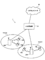
図1に、HetNetにおいて、ユーザ端末UEが基地局装置eNB(マクロセル)と小電力ノードLPN(ローパワーセル)の2つのセルに接続した状態を例示する。ユーザ端末UEは、キャリアアグリゲーションによってコンポーネントキャリアCC#1及びCC#2が割り当てられており、コンポーネントキャリア#CC1を介してマクロセルと接続し、コンポーネントキャリアCC#2を介してローパワーセルと接続している。小電力ノードLPNはセルが小さいので、ユーザ端末UEは基地局装置eNBよりも小電力ノードLPNに近い位置に存在する。
FIG. 1 illustrates a state in which a user terminal UE is connected to two cells of a base station apparatus eNB (macro cell) and a low power node LPN (low power cell) in HetNet. Component
LTE−Aの最新規格であるRel.11−LTEにおいては、それぞれのノード(基地局装置、小電力ノード)における受信タイミングを合わせることを目的として、上りリンクにおいて複数のCCに対して複数の送信タイミングを実現するMTA(Multiple Timing Advance)機能が導入される(例えば、非特許文献2参照)。なお、Rel.10−LTEまではユーザ端末UEは、単一の送信タイミング制御が行われている(TAまたはSingle TAと呼ばれる)。図1に示す例では、マクロセルは送信タイミングT1で上りリンク送信が行われ、ローパワーセルでは送信タイミングT1から所定時間遅延した送信タイミングT2で上りリンク送信が行われている。 Rel., The latest standard of LTE-A. In 11-LTE, MTA (Multiple Timing Advance) that realizes a plurality of transmission timings for a plurality of CCs in the uplink for the purpose of matching the reception timing in each node (base station apparatus, low power node). Functions are introduced (see, for example, Non-Patent Document 2). Note that Rel. Up to 10-LTE, the user terminal UE is subjected to single transmission timing control (referred to as TA or Single TA). In the example shown in FIG. 1, the macro cell performs uplink transmission at transmission timing T1, and the low power cell performs uplink transmission at transmission timing T2 delayed by a predetermined time from transmission timing T1.
また、LTE−Aにおいては、最大5つのCCを用いたキャリアアグリゲーションが実現される。一方、Rel.11−LTEに導入されるMTAにおいては、最大5つのCCを最大4つのTAG(TA Group)に分類し、TAG毎に送信タイミングを制御することができる。 In LTE-A, carrier aggregation using a maximum of five CCs is realized. On the other hand, Rel. In MTA introduced in 11-LTE, a maximum of five CCs can be classified into a maximum of four TAGs (TA Group), and transmission timing can be controlled for each TAG.
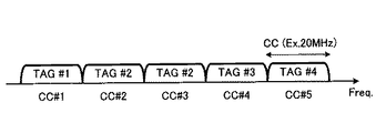
図2に、5つのCCが4つのTAGに分類された状態を例示する。図2においては、5つのCC#1〜CC#5を4つのTAG#1〜TAG#4に分類している。具体的には、CC#1に対してTAG#1、2つのCC#2及びCC#3に対して1つのTAG#2、CC#4に対してTAG#3、CC#5に対してTAG#4がそれぞれ割り当てられている。
FIG. 2 illustrates a state where five CCs are classified into four TAGs. In FIG. 2, five
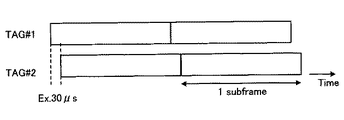
MTAが適用されたユーザ端末UEにおいて、TAG毎に上りリンクの送信タイミングを制御する場合、図3に示すように、TAG間の送信タイミング差は最大で30μs程度まで生じる。図3においては、例えば、TAG#1とTAG#2とで送信タイミングが30μsずれた状態を示している。なお、図3においては、縦軸に周波数(CC)を示し、横軸に時間を示している。
In the user terminal UE to which MTA is applied, when the uplink transmission timing is controlled for each TAG, the transmission timing difference between the TAGs is up to about 30 μs as shown in FIG. FIG. 3 shows a state in which the transmission timing is shifted by 30 μs between
ところで、LTE−Aシステムにおける上りリンクでは、CC単位且つサブフレーム単位で送信電力が制御されており、各サブフレームでのトータル送信電力が上限値を超えないように制御される。一方、Rel.11−LTEで導入されるMTAがユーザ端末UEに適用される場合、TAG間で上りリンクの物理チャネルの信号が重複する区間(以下、適宜「信号重複区間」という)が発生する可能性があり、この信号重複区間において所定の送信電力の上限値を超える可能性がある。 By the way, in the uplink in the LTE-A system, the transmission power is controlled in units of CC and in units of subframes, and the total transmission power in each subframe is controlled so as not to exceed the upper limit value. On the other hand, Rel. When MTA introduced in 11-LTE is applied to the user terminal UE, there is a possibility that a section in which uplink physical channel signals overlap between TAGs (hereinafter referred to as “signal overlapping section” as appropriate) occurs. In this signal overlap section, there is a possibility that the predetermined upper limit value of transmission power is exceeded.
MTAがユーザ端末UEに適用される場合に発生する信号重複区間としては、コンポーネントキャリア(CC)を跨いで同一サブフレーム番号の物理チャネル(信号)が重複する区間(フルオーバーラップ区間(Full Overlap:FO区間)と、コンポーネントキャリア(CC)を跨いで異なるサブフレーム番号の物理チャネル(信号)が局所的に重複する区間(局所オーバーラップ区間(Partial Overlap:PO区間)と、同一のTAG内で物理チャネル(信号)が重複する区間(同一TAGオーバーラップ区間(Same TAG Overlap:SO区間)とが想定される。 As a signal overlap section that occurs when MTA is applied to the user terminal UE, a section in which physical channels (signals) of the same subframe number overlap across component carriers (CC) (full overlap section (Full Overlap: FO section), a section in which physical channels (signals) with different subframe numbers across the component carrier (CC) overlap locally (local overlap section (PO section)), and physical in the same TAG A section in which channels (signals) overlap (same TAG overlap section (SO section)) is assumed.
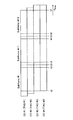
図4に、MTAがユーザ端末に適用される場合に想定される信号重複区間の一例を示す。図4においては、4つのCC#1〜CC#4が3つのTAG#1〜TAG#3に分類された状態を示している。具体的には、CC#1に対してTAG#1、CC#2に対してTAG#2、2つのCC#3及びCC#4に対して1つのTAG#3がそれぞれ割り当てられている。なお、図4においては、縦軸に周波数(CC)を示し、横軸に時間を示している。
FIG. 4 shows an example of a signal overlap section assumed when MTA is applied to a user terminal. FIG. 4 shows a state where four
図4に示す具体例では、時点t0と時点t1との間、時点t3と時点t4との間及び時点t6と時点t7との間において、TAG#1〜TAG#4間でFOが発生する。また、時点t1と時点t2との間及び時点t4と時点t5との間において、TAG#1及びTAG#2間でPOが発生し、TAG#2〜TAG#4間でFOが発生し、TAG#3及びTAG#4間でSOが発生する。さらに、時点t2と時点t3との間及び時点t5と時点t6との間において、TAG#1及びTAG#2間でFOが発生し、TAG#2〜TAG#4間でPOが発生し、TAG#3及びTAG#4間でSOが発生する。
In the specific example shown in FIG. 4, FO occurs between
このように発生する信号重複区間(FO区間、PO区間及びSO区間)において、ユーザ端末UEは、CC毎に規定される送信電力の上限値及び全てのCCのトータル送信電力の上限値を超えないように、電力補正(より具体的には、パワースケーリング)を行う必要がある。なお、本明細書において、パワースケーリングというときは、送信電力を低減するだけでなく、送信電力を0にする場合も含む。 In the signal overlap section (FO section, PO section, and SO section) generated in this way, the user terminal UE does not exceed the upper limit value of the transmission power defined for each CC and the upper limit value of the total transmission power of all CCs. Thus, it is necessary to perform power correction (more specifically, power scaling). In this specification, the term “power scaling” includes not only reducing the transmission power but also setting the transmission power to zero.
しかしながら、これらの信号重複区間(FO区間、PO区間及びSO区間)に対してパワースケーリングを適用すると、その信号重複区間に送信される物理チャネルの信号電力が低減するため、上りリンク伝送品質が劣化し得るという問題が発生する。 However, when power scaling is applied to these signal overlap sections (FO section, PO section, and SO section), the signal power of the physical channel transmitted in the signal overlap section is reduced, so that uplink transmission quality is degraded. The problem that can occur.
本発明は、かかる点に鑑みてなされたものであり、上りリンク伝送品質の劣化を抑制しつつ、上りリンクの送信電力が上限値を超える信号重複区間における電力補正を適用することができるユーザ端末、無線通信システム及び無線通信方法を提供することを目的とする。 The present invention has been made in view of such a point, and can suppress power degradation in uplink transmission and can apply power correction in a signal overlap section in which uplink transmission power exceeds an upper limit value. An object of the present invention is to provide a wireless communication system and a wireless communication method.
本発明に係るユーザ端末は、システム帯域を複数のコンポーネントキャリアで構成可能な無線通信システム上で、複数のコンポーネントキャリアを介して複数の無線基地局と通信可能なユーザ端末において、複数のコンポーネントキャリアが複数のタイミンググループに分類されていて、タイミンググループ毎に制御された送信タイミングにて上りリンクの物理チャネルを送信する送信部と、上りリンクの送信タイミングがタイミンググループ単位で制御されている場合、コンポーネントキャリアを跨いで同一サブフレーム番号の物理チャネルが重複するフルオーバーラップ区間の物理チャネルを優先して電力補正する電力制御部とを具備することを特徴とする。 A user terminal according to the present invention is a user terminal capable of communicating with a plurality of radio base stations via a plurality of component carriers on a radio communication system capable of configuring a system band with a plurality of component carriers. A component that is classified into a plurality of timing groups and transmits an uplink physical channel at a transmission timing controlled for each timing group, and a component in which uplink transmission timing is controlled in units of timing groups. A power control unit that preferentially corrects the power of a physical channel in a full overlap section in which physical channels with the same subframe number overlap across carriers;
本発明に係る無線通信システムは、システム帯域を複数のコンポーネントキャリアで構成可能な無線通信システムにおいて、それぞれセルを形成する複数の基地局装置と、複数のコンポーネントキャリアを介して1つ又は複数の前記基地局装置と通信可能なユーザ端末とを備え、前記基地局装置は、1つ又は複数のコンポーネントキャリアが分類されたタイミンググループ毎に上りリンクの送信タイミングを制御する制御部と、上りリンクを介して前記ユーザ端末から物理チャネルを受信する受信部と、を具備し、前記ユーザ端末は、タイミンググループ毎に制御された送信タイミングにて上りリンクの物理チャネルを送信する送信部と、上りリンクの送信タイミングがタイミンググループ単位で制御されている場合、コンポーネントキャリアを跨いで同一サブフレーム番号の物理チャネルが重複するフルオーバーラップ区間の物理チャネルを優先して電力補正する電力制御部とを具備することを特徴とする。 The radio communication system according to the present invention is a radio communication system in which a system band can be configured by a plurality of component carriers, and a plurality of base station apparatuses each forming a cell and one or a plurality of the above-described ones via a plurality of component carriers A user terminal capable of communicating with the base station apparatus, wherein the base station apparatus controls the uplink transmission timing for each timing group into which one or a plurality of component carriers are classified, and the uplink Receiving a physical channel from the user terminal, wherein the user terminal transmits an uplink physical channel at a transmission timing controlled for each timing group, and uplink transmission. If the timing is controlled in units of timing groups, component carry The across in the physical channel in the same sub-frame number in favor of the physical channel of the full-overlap interval overlapping characterized by comprising a power control unit for power correction.
本発明に係る無線通信方法は、複数セルが形成される無線通信システムにおける無線通信方法において、前記無線通信システムは、それぞれセルを形成する複数の基地局装置と、複数のコンポーネントキャリアを介して1つ又は複数の前記基地局装置と通信可能なユーザ端末とを備え、前記ユーザ端末において、タイミンググループ毎に制御された送信タイミングにて上りリンクの物理チャネルを送信するステップと、前記ユーザ端末において、上りリンクの送信タイミングがタイミンググループ単位で制御されている場合、コンポーネントキャリアを跨いで同一サブフレーム番号の物理チャネルが重複するフルオーバーラップ区間の物理チャネルを優先して電力補正するステップとを具備することを特徴とする。 A radio communication method according to the present invention is a radio communication method in a radio communication system in which a plurality of cells are formed. The radio communication system includes a plurality of base station apparatuses each forming a cell and a plurality of component carriers. A user terminal communicable with one or a plurality of the base station apparatus, in the user terminal, transmitting an uplink physical channel at a transmission timing controlled for each timing group; When uplink transmission timing is controlled in units of timing groups, the power correction is performed with priority given to physical channels in the full overlap section where physical channels with the same subframe number overlap across component carriers. It is characterized by that.
本発明によれば、上りリンク伝送品質の劣化を抑制しつつ、上りリンクの送信電力が上限値を超える信号重複区間における電力補正を適用することが可能となる。 According to the present invention, it is possible to apply power correction in a signal overlap section in which uplink transmission power exceeds an upper limit value while suppressing deterioration in uplink transmission quality.
上述したように、Rel.11−LTEで導入されるMTAがユーザ端末UEに適用される場合には、TAG間で信号重複区間が発生する可能性があり、この信号重複区間において所定の送信電力の上限値を超える可能性がある。このため、ユーザ端末UEにおいては、各信号重複区間において、CC毎に規定される送信電力の上限値及び全てのCCのトータル送信電力の上限値を超えないように、電力補正(パワースケーリング)を行う必要がある。しかしながら、これらの信号重複区間にランダムにパワースケーリングを適用すると、その信号重複区間における信号電力が低減して上りリンク伝送品質が劣化し得る。一方で、上りリンク伝送品質の劣化は、各信号重複区間に対するパワースケーリングの適用順序に依存する。本発明者は、このように信号重複区間に対するパワースケーリングの適用の優先順位を予め定めておくことで上りリンク伝送品質の劣化を抑制できることに着目し、本発明に想到した。 As described above, Rel. When the MTA introduced in 11-LTE is applied to the user terminal UE, there is a possibility that a signal overlap section may occur between TAGs, and there is a possibility that the upper limit value of a predetermined transmission power is exceeded in this signal overlap section. There is. For this reason, in the user terminal UE, in each signal overlap section, power correction (power scaling) is performed so as not to exceed the upper limit value of transmission power defined for each CC and the upper limit value of total transmission power of all CCs. There is a need to do. However, if power scaling is randomly applied to these signal overlap sections, the signal power in the signal overlap section may be reduced and the uplink transmission quality may be degraded. On the other hand, the degradation of uplink transmission quality depends on the application order of power scaling for each signal overlap section. The inventor of the present invention has arrived at the present invention by paying attention to the fact that the degradation of the uplink transmission quality can be suppressed by predetermining the priority of application of power scaling to the signal overlapping section in this way.
すなわち、本発明の骨子は、セルを形成する複数の基地局装置eNBと、複数のコンポーネントキャリアを介して1つ又は複数の基地局装置eNBと通信可能なユーザ端末UEとを備えた無線通信システムにおいて、ユーザ端末UEがTAG毎に制御された送信タイミングにて上りリンクの物理チャネルを送信する場合に、コンポーネントキャリアを跨いで同一サブフレーム番号の物理チャネルが重複するFO区間の物理チャネルを優先して電力補正(パワースケーリング)することにある。これにより、PO区間やSO区間の物理チャネルに優先してFO区間の物理チャネルを電力補正できるので、PO区間等の物理チャネルを優先して電力補正を行う場合に発生する上りリンク伝送品質の劣化を最小化できる。この結果、上りリンク伝送品質の劣化を抑制しつつ、上りリンクの送信電力が上限値を超える信号重複区間におけるパワースケーリングを適用することが可能となる。 That is, the gist of the present invention is a wireless communication system including a plurality of base station apparatuses eNB forming a cell and a user terminal UE capable of communicating with one or a plurality of base station apparatuses eNB via a plurality of component carriers. In this case, when the user terminal UE transmits an uplink physical channel at a transmission timing controlled for each TAG, priority is given to the physical channel in the FO section where the physical channels having the same subframe number overlap across the component carriers. Power correction (power scaling). As a result, the power of the physical channel of the FO section can be corrected with priority over the physical channel of the PO section or SO section, and therefore the uplink transmission quality degradation that occurs when the power correction is performed with priority on the physical channel of the PO section or the like. Can be minimized. As a result, it is possible to apply power scaling in a signal overlap section in which uplink transmission power exceeds an upper limit value while suppressing degradation of uplink transmission quality.
以下、図1に示すネットワーク構成を参照して具体的に説明する。図1において、ユーザ端末UEは、マクロセル(基地局装置eNB)に接続すると共に、ローパワーセル(小電力ノードLPN)に接続している。なお、本発明において、ユーザ端末UEが同時接続可能なセル数は2セルに限定されない。基地局装置eNBと小電力ノードLPNとはバックホールリンクを介して接続されており、基地局装置eNBから小電力ノードLPNを制御している。小電力ノードLPNは、基地局装置eNBからバックホールリンクを介してユーザ端末UEとの通信に必要な情報(例えば、TAG情報)を受け取る。 A specific description will be given below with reference to the network configuration shown in FIG. In FIG. 1, a user terminal UE is connected to a macro cell (base station apparatus eNB) and is connected to a low power cell (low power node LPN). In the present invention, the number of cells to which the user terminal UE can be connected simultaneously is not limited to two cells. The base station apparatus eNB and the low power node LPN are connected via a backhaul link, and the low power node LPN is controlled from the base station apparatus eNB. The small power node LPN receives information (for example, TAG information) necessary for communication with the user terminal UE from the base station apparatus eNB via the backhaul link.
基地局装置eNBは、キャリアアグリゲーションによってユーザ端末UEに対して複数のコンポーネントキャリアCC#1、CC#2を割り当てると共に、一方のコンポーネントキャリアCC#1をマクロセルに割り当て、もう一方のコンポーネントキャリアCC#2をローパワーセルに割り当てるように、セル構成をユーザ端末UEに指示する。また、基地局装置eNBは、ユーザ端末UEに複数のコンポーネントキャリアを割り当て、複数のセルに同時接続するようにセル構成した場合は、ユーザ端末UEに割り当てた複数のコンポーネントキャリアをTAGに分類し、TAG毎の送信タイミングの制御を行う。図1に示される例では、マクロセルに割り当てられたCC#1はTAG#1に分類され、ローパワーセルに割り当てられたCC#2はTAG#2に分類されている。
The base station apparatus eNB assigns a plurality of component
ユーザ端末UEは、複数のコンポーネントキャリアCC#1、CC#2を介して、上りリンク物理制御チャネル、上りリンク物理データチャネルを送信できる。具体的には、ユーザ端末UEは、マクロセル(TAG#1、CC#1)の通信では上りリンクのサブフレームの送信タイミングを送信タイミングT1に制御し、ローパワーセル(TAG#2、CC#2)の通信では上りリンクのサブフレームの送信タイミングを送信タイミングT2に制御する。このとき、TAG#1とTAG#2とで上りリンクの送信タイミング(T1、T2)が異なるので、PO区間を含む信号重複区間が発生する(図4参照)。
The user terminal UE can transmit an uplink physical control channel and an uplink physical data channel via a plurality of component
基地局装置eNBによりTAG毎の上りリンク信号の送信タイミングが制御される場合、ユーザ端末UEは、コンポーネントキャリア(CC)を跨いで同一サブフレーム番号の物理チャネルが重複するFO区間の物理チャネルを優先して電力補正(パワースケーリング)を行う。この場合、ユーザ端末UEは、例えば、CCを跨いで異なるサブフレーム番号の物理チャネルが局所的に重複するPO区間の物理チャネルや、同一のTAG内で物理チャネルが重複するSO区間の物理チャネルに優先して電力補正(パワースケーリング)を行うことができる。 When the transmission timing of the uplink signal for each TAG is controlled by the base station apparatus eNB, the user terminal UE gives priority to the physical channel in the FO section where the physical channels having the same subframe number overlap across the component carriers (CC). Power correction (power scaling). In this case, for example, the user terminal UE may be connected to a physical channel in a PO section where physical channels with different subframe numbers locally overlap across CCs, or a physical channel in an SO section where physical channels overlap in the same TAG. Power correction (power scaling) can be performed with priority.
詳細について後述するように、FO区間の物理チャネルを優先することなくパワースケーリングを行うと、FO区間の物理チャネルを優先してパワースケーリングを行う場合と比べて、PO区間の物理チャネルの信号電力が低減され、上りリンク伝送品質が劣化する事態が発生し得る。上述のように、FO区間の物理チャネルを優先してパワースケーリングを行うことにより、PO区間の物理チャネルの信号電力が低減される事態を回避できるので、PO区間の物理チャネルを優先して電力補正を行う場合に発生する上りリンク伝送品質の劣化を最小化でき、上りリンク伝送品質の劣化を抑制することが可能となる。 As will be described in detail later, when power scaling is performed without giving priority to the physical channel in the FO section, the signal power of the physical channel in the PO section is higher than when power scaling is performed with priority on the physical channel in the FO section. As a result, the uplink transmission quality may be degraded. As described above, by performing power scaling with priority on the physical channel in the FO section, it is possible to avoid a situation in which the signal power of the physical channel in the PO section is reduced, so power correction is performed with priority on the physical channel in the PO section. It is possible to minimize the degradation of the uplink transmission quality that occurs when performing the transmission, and to suppress the degradation of the uplink transmission quality.
また、FO区間の物理チャネルを優先することなくパワースケーリングを行う場合には、PO区間の物理チャネルにパワースケーリングを行った後に、該当するPO区間を含むサブフレームに対応するFO区間に再びパワースケーリングを行う事態(すなわち、同一信号重複区間に対して複数回パワースケーリングが行われる事態)が発生し得る。上述のように、FO区間の物理チャネルを優先してパワースケーリングを行うことにより、ユーザ端末UEにおけるパワースケーリングの処理回数を低減できるので、ユーザ端末UEにおける制御を簡素化できると共に、パワースケーリングに伴う電力消費を低減することが可能となる。 When power scaling is performed without giving priority to the physical channel in the FO section, power scaling is performed on the physical channel in the PO section, and then power scaling is performed again on the FO section corresponding to the subframe including the corresponding PO section. (That is, a situation where power scaling is performed a plurality of times for the same signal overlap section) may occur. As described above, by performing power scaling by giving priority to the physical channel in the FO section, the number of power scaling processes in the user terminal UE can be reduced, so that control in the user terminal UE can be simplified and accompanied by power scaling. It becomes possible to reduce power consumption.
また、FO区間の物理チャネルを優先してパワースケーリングを行う場合、ユーザ端末UEは、CC毎に規定される送信電力の上限値と、全てのCCのトータル送信電力の上限値とをそれぞれ満たすように(すなわち、双方の上限値を超えないように)、パワースケーリングを行う。このようにCC毎に規定される送信電力の上限値及び全てのCCのトータル送信電力の上限値を超えないように電力補正が行われるので、予め定められた送信電力の許容範囲内で送信電力を有効に補正してFO区間の上りリンクの物理チャネルを送信することが可能となる。 In addition, when performing power scaling by giving priority to the physical channel in the FO section, the user terminal UE satisfies the upper limit value of transmission power defined for each CC and the upper limit value of total transmission power of all CCs. (Ie, do not exceed the upper limit of both), power scaling is performed. In this way, power correction is performed so as not to exceed the upper limit value of the transmission power defined for each CC and the upper limit value of the total transmission power of all CCs, so the transmission power is within the predetermined allowable range of transmission power. Is effectively corrected, and the uplink physical channel in the FO section can be transmitted.
ここで、FO区間の物理チャネルを優先してパワースケーリングを行う場合の送信電力の推移について説明する。図5は、FO区間の物理チャネルを優先してパワースケーリングを行う場合の送信電力の推移の説明図である。以下においては、例えば、図1に示すHetNetにおいて、CC#1(TAG#1)を用いて物理上り共有チャネル(PUSCH)をマクロセルに送信し、CC#2(TAG#2)を用いてPUSCHをローパワーセルに送信する場合について説明する。なお、ここでは、CC毎に規定される送信電力の上限値が100mWであり、全てのCC(CC#1、CC#2)のトータル送信電力の上限値が200mWであるものとする。
Here, transition of transmission power when power scaling is performed with priority on the physical channel in the FO section will be described. FIG. 5 is an explanatory diagram of transition of transmission power when power scaling is performed with priority on the physical channel in the FO section. In the following, for example, in HetNet shown in FIG. 1, a physical uplink shared channel (PUSCH) is transmitted to a macro cell using CC # 1 (TAG # 1), and PUSCH is transmitted using CC # 2 (TAG # 2). A case of transmitting to a low power cell will be described. Here, the upper limit value of the transmission power defined for each CC is 100 mW, and the upper limit value of the total transmission power of all CCs (
なお、図5に示す例では、時点t0と時点t1との間及び時点t2と時点t3との間において、TAG#1及びTAG#2間でFO区間が発生しており、時点t1と時点t2との間において、TAG#1及びTAG#2間でPO区間が発生した場合について示している。また、図5においては、説明の便宜上、パワースケーリング実行前において、ユーザ端末UEは、マクロセル及びローパワーセルの双方に対してPUSCHを200mWの送信電力にて送信するものとする。
In the example shown in FIG. 5, an FO section occurs between
また、ユーザ端末UEは、均等に信号電力を低減させる均等パワースケーリング(Equal power scaring)を行うものとする。ここで、FO区間の物理チャネルに対するパワースケーリングを行う際、ユーザ端末UEは、サブフレーム単位で均等パワースケーリングを行うことができる。一方、PO区間の物理チャネルに対するパワースケーリングを行う際、ユーザ端末UEは、該当するPO区間にのみ均等パワースケーリングを行うことができる。 Moreover, the user terminal UE shall perform equal power scaling which reduces signal power equally. Here, when performing power scaling on the physical channel in the FO section, the user terminal UE can perform equal power scaling on a subframe basis. On the other hand, when performing power scaling on the physical channel in the PO section, the user terminal UE can perform equal power scaling only in the corresponding PO section.
FO区間の物理チャネルを優先してパワースケーリングを行う場合、ユーザ端末UEは、まず、サブフレーム#iにおけるFO区間の送信電力に着目し、均等パワースケーリングを行う。これにより、サブフレーム#iにおけるTAG#1及びTAG#2の双方のPUSCHの送信電力が200mWから100mWに補正される(図5における第2段目)。次に、ユーザ端末UEは、サブフレーム#i+1におけるFO区間の送信電力に着目し、均等パワースケーリングを行う。これにより、サブフレーム#i+1におけるTAG#1及びTAG#2の双方のPUSCHの送信電力が200mWから100mWに補正される(図5における第3段目)。
When performing power scaling by giving priority to the physical channel in the FO section, the user terminal UE first performs equal power scaling by paying attention to the transmission power in the FO section in subframe #i. Thereby, the transmission power of PUSCH of both
このようにサブフレーム#i+1におけるFO区間にパワースケーリングが行われると、時点t1と時点t2との間のPO区間における送信電力が、全てのCCのトータル送信電力の上限値を超過した事態が解消されていることが分かる。したがって、ユーザ端末UEは、このPO区間に対してパワースケーリングを行う必要はない(図5における第4段目)。このため、図5に示す例において、FO区間の物理チャネルを優先してパワースケーリングを行う場合、ユーザ端末UEは、2回のパワースケーリングを行うのみで、予め定められた送信電力の許容範囲内で送信電力を有効に補正してFO区間の上りリンクの物理チャネルを送信することが可能となる。 As described above, when power scaling is performed in the FO section in subframe # i + 1, the situation in which the transmission power in the PO section between time t1 and time t2 exceeds the upper limit of the total transmission power of all CCs is resolved. You can see that. Therefore, the user terminal UE does not need to perform power scaling for this PO section (fourth stage in FIG. 5). Therefore, in the example illustrated in FIG. 5, when performing power scaling with priority given to the physical channel in the FO section, the user terminal UE only performs power scaling twice and is within a predetermined transmission power allowable range. Thus, it is possible to transmit the uplink physical channel in the FO section by effectively correcting the transmission power.
図6は、FO区間の物理チャネルを優先しないでパワースケーリングを行う場合の送信電力の推移の説明図である。なお、図6においては、時系列的に信号重複区間のパワースケーリングを行う場合について説明するものとする。なお、CCとTAGとの割り当て及びTAG間で発生する信号重複区間、並びに、各CCから送信される物理チャネル及びその送信電力については、図5に示す条件と同一であるものとする。 FIG. 6 is an explanatory diagram of transition of transmission power when power scaling is performed without giving priority to the physical channel in the FO section. In addition, in FIG. 6, the case where the power scaling of a signal overlap area is performed in time series shall be demonstrated. It is assumed that CC and TAG allocation, signal overlap sections generated between TAGs, physical channels transmitted from each CC, and transmission power thereof are the same as the conditions shown in FIG.
時系列的に信号重複区間のパワースケーリングを行う場合においても、ユーザ端末UEは、まず、サブフレーム#iにおけるFO区間の送信電力に着目し、均等パワースケーリングを行う。これにより、サブフレーム#iにおけるTAG#1及びTAG#2の双方のPUSCHの送信電力が200mWから100mWに補正される(図6における第2段目)。
Even when performing power scaling of signal overlapping sections in time series, the user terminal UE first performs equal power scaling by paying attention to the transmission power of the FO section in subframe #i. Thereby, the transmission power of PUSCH of both
次に、ユーザ端末UEは、時点t1と時点t2との間のPO区間の送信電力に着目する。時点t1と時点t2との間のPO区間においては、TAG#2のPUSCHの送信電力が100mWであるのに対し、TAG#1のPUSCHの送信電力が200mWであり、全てのCCのトータル送信電力の上限値を超えている。このため、ユーザ端末UEは、このPO区間における信号電力に対して均等パワースケーリングを行う。これにより、TAG#1におけるPO区間の送信電力が200mWから133mWに補正されると共に、TAG#2におけるPO区間の送信電力が100mWから67mWに補正される(図6における第3段目)。
Next, the user terminal UE pays attention to the transmission power in the PO section between the time point t1 and the time point t2. In the PO section between time t1 and time t2, the transmission power of PUSCH of
続いて、ユーザ端末UEは、サブフレーム#i+1におけるFO区間の送信電力に着目し、均等パワースケーリングを行う。これにより、サブフレーム#i+1におけるTAG#1及びTAG#2の双方のPUSCHの送信電力が200mWから100mWに補正される(図6における第4段目)。このように時系列的に信号重複区間のパワースケーリングを行う場合、ユーザ端末UEは、3回のパワースケーリングを行う必要がある。そして、TAG#2における時点t1と時点t2との間のPO区間の送信電力は67mWに設定される。このため、このPO区間における物理チャネルに関し、FO区間の物理チャネルを優先してパワースケーリングを行う場合と比べて上りリンク伝送品質が劣化し得る。
Subsequently, the user terminal UE pays attention to the transmission power in the FO section in the subframe # i + 1 and performs equal power scaling. Thereby, the transmission power of PUSCH of both
なお、FO区間の物理チャネルを優先してパワースケーリングを行う場合において、3つ以上のCCに同時接続するように構成されている場合、ユーザ端末UEは、パワースケーリングを適用する複数(2つ以上)のCCをランダムに選択することができる。これにより、特定のCCにおけるFO区間の物理チャネルが集中してパワースケーリングが行われる事態が防止されることから、特定のCCにおけるFO区間の物理チャネルに対応する上りリンク伝送品質が劣化する事態を抑制することが可能となる。 In addition, when performing power scaling by giving priority to the physical channel in the FO section, when configured to connect to three or more CCs simultaneously, the user terminal UE applies a plurality of (two or more) power scalings. ) CC can be selected at random. This prevents a situation in which physical channels in the FO section in a specific CC are concentrated and power scaling is performed, so that the uplink transmission quality corresponding to the physical channel in the FO section in the specific CC deteriorates. It becomes possible to suppress.
また、FO区間の物理チャネルを優先してパワースケーリングを行う場合において、3つ以上のCCに同時接続するように構成されている場合、ユーザ端末UEは、パワースケーリングを適用するCCを巡回的に選択するようにしてもよい。これにより、パワースケーリングが適用されるCCが分散されることから、特定のCCにおけるFO区間の物理チャネルが集中してパワースケーリングが行われる事態を防止することが可能となる。この結果、特定のCCにおけるFO区間の物理チャネルに対応する上りリンク伝送品質が劣化する事態を抑制することが可能となる。 Further, in the case where power scaling is performed with priority given to the physical channel in the FO section, when configured to be simultaneously connected to three or more CCs, the user terminal UE cyclically selects CCs to which power scaling is applied. You may make it select. As a result, since CCs to which power scaling is applied are distributed, it is possible to prevent a situation where power scaling is performed due to concentration of physical channels in an FO section in a specific CC. As a result, it is possible to suppress a situation in which the uplink transmission quality corresponding to the physical channel in the FO section in a specific CC deteriorates.
さらに、FO区間の物理チャネルを優先してパワースケーリングを行う場合において、ユーザ端末UEは、予め定められた物理チャネル毎の優先度に基づいてパワースケーリングを適用する。例えば、ユーザ端末UEは、パワースケーリングが適用される物理チャネルのセットが種別の異なる2つの物理チャネルで構成される場合に、予め定められた物理チャネル毎の優先度に基づいてパワースケーリングを適用することができる。 Furthermore, when performing power scaling by giving priority to the physical channel in the FO section, the user terminal UE applies power scaling based on a predetermined priority for each physical channel. For example, when the set of physical channels to which power scaling is applied is composed of two different physical channels, the user terminal UE applies power scaling based on a predetermined priority for each physical channel be able to.
物理チャネル毎の優先度については、例えば、スループット特性等への影響を考慮した信号の重要度に基づいて、チャネル品質測定用の参照信号(SRS:Sounding Reference Signal)、物理上り共有チャネル(PUSCH:Physical Uplink Shared Channel)、物理上り制御チャネル(PUCCH:Physical Uplink Control Channel)及び物理ランダムアクセスチャネル(PRACH:Physical Random Access Channel)の順序に定めることができる。すなわち、パワースケーリングの適用に関し、SRSにおける優先度を最も高くする一方、PRACHにおける優先度を最も低くするように定めることができる。なお、これらの優先度は、対象となる物理チャネルが制御信号を含んでいるか否かに応じて定める場合に相当する。 With regard to the priority for each physical channel, for example, based on the importance of the signal considering the influence on the throughput characteristics and the like, a reference signal for measuring channel quality (SRS: Sounding Reference Signal), a physical uplink shared channel (PUSCH: It can be determined in the order of Physical Uplink Shared Channel (PHY), Physical Uplink Control Channel (PUCCH), and Physical Random Access Channel (PRACH: Physical Random Access Channel). That is, regarding the application of power scaling, the priority in SRS can be made highest while the priority in PRACH can be made lowest. Note that these priorities correspond to cases in which the priority is determined according to whether or not the target physical channel includes a control signal.
なお、Rel.10−LTEでは、CC単位で制御される上りリンク物理チャネルとして、これらのPRACH、PUCCH、PUSCH及びSRSを規定している。PRACHは、ユーザ端末UEからネットワークへの初期アクセス時に使用される。ユーザ端末UEは、セルサーチで検出した下りのCCから必要な報知情報として、PRACHのパラメータ(周波数位置、サブフレーム位置、Zadoff−Chu系列番号等)、上りのCCの情報(中心周波数、帯域幅等)等を受信し、下りに対応する上りのCCでPRACHを送信する。PUCCHは、帯域の両端に多重(サブフレーム内周波数ホッピングを適用)され、下りリンクの送信信号に対する応答信号(response)であるACK/NACK、CQI(Channel Quality indicator)レポート、スケジューリングリクエストを運ぶ。CQIとは受信したデータの品質、若しくは通信路品質を示す品質情報である。PUSCHには、UL−SCH(トランスポートチャネルの1つである上り共有チャネル)がマッピングされる。 Note that Rel. In 10-LTE, these PRACH, PUCCH, PUSCH, and SRS are prescribed | regulated as an uplink physical channel controlled per CC. PRACH is used at the time of initial access from the user terminal UE to the network. The user terminal UE provides PRACH parameters (frequency position, subframe position, Zadoff-Chu sequence number, etc.) and uplink CC information (center frequency, bandwidth) as necessary broadcast information from the downlink CC detected by the cell search. Etc.) and the PRACH is transmitted on the uplink CC corresponding to the downlink. The PUCCH is multiplexed at both ends of the band (intra-subframe frequency hopping is applied), and carries ACK / NACK that is a response signal (response) to a downlink transmission signal, a CQI (Channel Quality Indicator) report, and a scheduling request. CQI is quality information indicating the quality of received data or channel quality. UL-SCH (uplink shared channel which is one of the transport channels) is mapped to PUSCH.
ここで、予め定められた物理チャネル毎の優先度に基づいてパワースケーリングを適用する場合の具体例について説明する。図7は、複数のTAG間における電力補正対象テーブルの一例を示す図である。図7に示す電力補正対象テーブルにおいては、複数のTAGに割り当てられた物理チャネルのセットと、電力補正対象となる物理チャネルとが定められている。なお、図7に示す電力補正対象テーブルにおいては、説明の便宜上、2つのTAG#X及びTAG#Yに割り当てられた物理チャネルを示している。しかしながら、電力補正対象テーブルに定められるTAGの数量については、これに限定されず、適宜変更が可能である。 Here, a specific example in the case of applying power scaling based on a predetermined priority for each physical channel will be described. FIG. 7 is a diagram illustrating an example of a power correction target table between a plurality of TAGs. In the power correction target table shown in FIG. 7, a set of physical channels assigned to a plurality of TAGs and physical channels that are power correction targets are defined. In the power correction target table shown in FIG. 7, for convenience of explanation, physical channels assigned to two TAG # X and TAG # Y are shown. However, the number of TAGs defined in the power correction target table is not limited to this, and can be changed as appropriate.
図7に示す電力補正対象テーブルにおいては、TAG#X及びTAG#Yにおいて、同一の物理チャネルが割り当てられる場合、基地局装置eNBから予め通知され、或いは、ユーザ端末UEの運用で予め定められたTAGの物理チャネルが電力補正対象として登録されている。また、TAG#X及びTAG#Yにおいて、異なる種別の物理チャネルが割り当てられる場合、上述した優先度に応じて、パワースケーリングの適用の優先度が高い物理チャネルが電力補正対象として登録されている。 In the power correction target table illustrated in FIG. 7, when the same physical channel is allocated in TAG # X and TAG # Y, the base station apparatus eNB notifies the base station apparatus eNB in advance, or the user terminal UE operates in advance. A TAG physical channel is registered as a power correction target. In addition, when different types of physical channels are allocated in TAG # X and TAG # Y, physical channels with higher priority for application of power scaling are registered as power correction targets according to the above-described priorities.
例えば、TAG#XにSRSが割り当てられ、TAG#YにPUSCHが割り当てられる場合には、SRSが電力補正対象として登録されている(図7の番号2)。また、TAG#XにPUSCHが割り当てられ、TAG#YにPUCCHが割り当てられる場合には、PUSCHが電力補正対象として登録されている(図7の番号6)。さらに、TAG#XにPUCCHが割り当てられ、TAG#YにPRACHが割り当てられる場合には、PUCCHが電力補正対象として登録されている(図7の番号9)。
For example, when SRS is assigned to TAG # X and PUSCH is assigned to TAG # Y, SRS is registered as a power correction target (
したがって、FO区間の物理チャネルを優先してパワースケーリングを行う場合において、TAG#XにSRSが割り当てられ、TAG#YにPUSCHが割り当てられる場合には、ユーザ端末UEは、TAG#Xに割り当てられたSRSの送信電力を減少させる。同様に、TAG#XにPUSCHが割り当てられ、TAG#YにPUCCHが割り当てられる場合には、ユーザ端末UEは、TAG#Xに割り当てられたPUSCHの送信電力を減少させる。 Therefore, when power scaling is performed with priority given to the physical channel in the FO section, when SRS is assigned to TAG # X and PUSCH is assigned to TAG # Y, the user terminal UE is assigned to TAG # X. Reduce the transmission power of the SRS. Similarly, when the PUSCH is assigned to TAG # X and the PUCCH is assigned to TAG # Y, the user terminal UE decreases the transmission power of the PUSCH assigned to TAG # X.
図7に示す電力補正対象テーブルにおいては、2つのTAG#X及びTAG#Yに割り当てられた物理チャネルのセット(以下、適宜「物理チャネルセット」という)の電力補正対象を特定することができる。なお、複数のCCに3つ以上のTAGが割り当てられる場合には、この物理チャネルセットが複数存在することとなる。例えば、図8に示すように、CC#1にTAG#1が割り当てられ、CC#2にTAG#2が割り当てられ、CC#3にTAG#3が割り当てられる場合を想定する。この場合には、電力補正が適用される物理チャネルセットとして、TAG#1で送信されるPUCCH及びTAG#2で送信されるPRACHの第1の物理チャネルセットと、TAG#2で送信されるPRACH及びTAG#3で送信されるPUSCHの第2の物理チャネルセットとが存在する。
In the power correction target table shown in FIG. 7, it is possible to specify the power correction target of a set of physical channels (hereinafter referred to as “physical channel set” as appropriate) assigned to two TAG # X and TAG # Y. When three or more TAGs are assigned to a plurality of CCs, a plurality of physical channel sets exist. For example, as shown in FIG. 8, it is assumed that
このように電力補正が適用される複数の物理チャネルセットが存在する場合、例えば、ユーザ端末UEは、制御信号を含まない物理チャネルが含まれる物理チャネルセットを優先してパワースケーリングの適用対象に選択することができる。その上で、ユーザ端末UEは、図7に示すような電力補正対象テーブルの登録内容に従って電力補正対象となる物理チャネルを決定する。なお、PUCCH及びPRACHは、制御信号を含む物理チャネルを構成し、PUSCH及びSRSは、制御信号を含まない物理チャネルを構成する。 When there are a plurality of physical channel sets to which power correction is applied in this way, for example, the user terminal UE preferentially selects a physical channel set that includes a physical channel that does not include a control signal as a power scaling application target. can do. Then, the user terminal UE determines a physical channel that is a power correction target in accordance with the registered content of the power correction target table as shown in FIG. Note that PUCCH and PRACH constitute a physical channel including a control signal, and PUSCH and SRS constitute a physical channel not including a control signal.
以下、図8に示す具体例を用いて説明する。例えば、図8に示す第1の物理チャネルセットを構成するPUCCH及びPRACHには、いずれも制御信号が含まれる。一方、第2の物理チャネルセットを構成するPRACH及びPUSCHには、前者には制御信号が含まれるものの、後者には制御信号が含まれない。このため、ユーザ端末UEは、第2の物理チャネルセットを電力補正の適用対象として選択することができる。その上で、ユーザ端末UEは、図7に示す電力補正対象テーブルの登録内容(図7の番号7)に従って電力補正対象となる物理チャネルとして、PUSCH(TAG#3)を決定する。
Hereinafter, description will be made using a specific example shown in FIG. For example, the PUCCH and the PRACH constituting the first physical channel set shown in FIG. On the other hand, the PRACH and PUSCH constituting the second physical channel set include a control signal in the former, but do not include a control signal in the latter. For this reason, the user terminal UE can select the second physical channel set as a power correction application target. Then, the user terminal UE determines PUSCH (TAG # 3) as a physical channel that is a power correction target in accordance with the registered content (
電力補正の適用対象となる物理チャネルセットの選択方法については、上述した物理チャネルの優先度と同様に、スループット特性等への影響を考慮した信号の重要度に基づいて定めることが好ましい。例えば、SRS、PUSCH、PUCCH及びPRACHの順序に基づいて、電力補正の適用対象となる物理チャネルセットを選択できる。この場合、電力補正の適用対象となる物理チャネルセットは、図7に示す順序で選択される。すなわち、電力補正の適用に関し、図7の番号1に示すSRS及びSRSを含む物理チャネルセットの優先度が最も高く、図7の番号10に示すPRACH及びPRACHを含む物理チャネルセットの優先度が最も低く設定される。
The method for selecting the physical channel set to which power correction is applied is preferably determined based on the importance of the signal in consideration of the influence on the throughput characteristics and the like, similar to the priority of the physical channel described above. For example, based on the order of SRS, PUSCH, PUCCH, and PRACH, a physical channel set to be applied with power correction can be selected. In this case, the physical channel set to which power correction is applied is selected in the order shown in FIG. That is, regarding the application of power correction, the priority of the physical channel set including SRS and SRS indicated by
なお、以上の説明においては、信号重複区間が発生する場合にFO区間の物理チャネルを優先してパワースケーリングを適用することを前提として説明している。しかしながら、信号重複区間に対してパワースケーリングを適用する方法については、これに限定されるものではなく適宜変更が可能である。例えば、FO区間の物理チャネルを優先してパワースケーリングを適用することなく、予め定められた物理チャネル毎の優先度に基づいてパワースケーリングを適用することができる(変形例1)。例えば、ユーザ端末UEは、SRS、PUSCH、PUCCH及びPRACHの順序に応じてパワースケーリングを適用することができる。この場合、例えば、図7に示すような電力補正対象テーブルを利用することが好ましい。 In the above description, it is assumed that power scaling is applied with priority given to the physical channel in the FO section when a signal overlap section occurs. However, the method of applying power scaling to the signal overlap section is not limited to this and can be changed as appropriate. For example, power scaling can be applied based on a predetermined priority for each physical channel without applying power scaling in preference to the physical channel in the FO section (Modification 1). For example, the user terminal UE can apply power scaling according to the order of SRS, PUSCH, PUCCH, and PRACH. In this case, for example, it is preferable to use a power correction target table as shown in FIG.
特に、電力補正が適用される複数の物理チャネルセットが存在する場合には(図8参照)、制御信号を含まない物理チャネルが含まれる物理チャネルのセットを優先してパワースケーリングの適用対象に選択する。その上で、ユーザ端末UEは、図7に示すような電力補正対象テーブルの登録内容に従って電力補正対象となる物理チャネルを決定することができる。 In particular, when there are multiple physical channel sets to which power correction is applied (see Fig. 8), priority is given to the set of physical channels that include physical channels that do not include control signals, and are selected as power scaling application targets. To do. In addition, the user terminal UE can determine a physical channel that is a power correction target according to the registered contents of the power correction target table as shown in FIG.
また、セカンダリセル(Scell)に割り当てられるTAGに対応する物理チャネルを、プライマリセル(Pcell)に割り当てられるTAGに対応する物理チャネルよりも優先してパワースケーリングを行うこともできる(変形例2)。Pcellにおいては、制御信号など上りリンクの伝送品質を保つために必要な信号が多く通信される。上述のように、Scellに対応する物理チャネルを、Pcellに対応する物理チャネルよりも優先的にパワースケーリングすることにより、Pcellに対応する物理チャネルの送信電力の低下を回避して上りリンク伝送品質の劣化を抑制することが可能となる。 Moreover, power scaling can also be performed with priority given to a physical channel corresponding to a TAG assigned to a secondary cell (Scell) over a physical channel corresponding to a TAG assigned to a primary cell (Pcell) (Modification 2). In Pcell, many signals such as control signals necessary for maintaining uplink transmission quality are communicated. As described above, the physical channel corresponding to Scell is power-scaled preferentially over the physical channel corresponding to Pcell, thereby avoiding a decrease in transmission power of the physical channel corresponding to Pcell and improving the uplink transmission quality. Deterioration can be suppressed.
なお、これらの変形例1及び変形例2を組み合わせても良い。変形例1及び変形例2を組み合わせる場合には、図7に示す電力補正対象テーブルに登録される内容に、TAG#X(又はTAG#Y)がPcell又はScellであるかを示す識別情報を追加することが好ましい。この場合には、電力補正対象テーブルの内容に応じて電力補正対象となる物理チャネルを効率的に特定することが可能となる。
In addition, you may combine these
さらに、各種の信号重複区間で送信される物理チャネルのうち、特定の信号重複区間で送信される特定の物理チャネルのみにパワースケーリングを行うこともできる(変形例3)。この場合、例えば、特定の信号重複区間としてPO区間を指定すると共に、特定の物理チャネルとしてPUSCHを指定することが考えられる。このようにPO区間で送信されるPUSCHに限ってパワースケーリングを行う場合には、電力補正対象を一部の物理チャネルに限定できるので、既存の仕様に大きな変更を必要とすることなく上りリンク伝送品質の劣化を抑制することが可能となる。 Furthermore, it is also possible to perform power scaling only on a specific physical channel transmitted in a specific signal overlap section among the physical channels transmitted in various signal overlap sections (Modification 3). In this case, for example, it is conceivable to specify the PO section as a specific signal overlap section and specify the PUSCH as a specific physical channel. In this way, when power scaling is performed only for the PUSCH transmitted in the PO section, the power correction target can be limited to a part of physical channels, so uplink transmission is not required to make significant changes to existing specifications. It becomes possible to suppress degradation of quality.
さらに、図6に示したように、ユーザ端末UEは、時系列的に信号重複区間のパワースケーリングを行うこともできる(変形例4)。この場合には、時系列的に信号重複区間のパワースケーリングが行われるので、信号重複区間の種別に関わらず、連続的にパワースケーリングを行うことができる。 Furthermore, as illustrated in FIG. 6, the user terminal UE can also perform power scaling in the signal overlap section in time series (Modification 4). In this case, since power scaling is performed in a signal overlapping section in time series, power scaling can be performed continuously regardless of the type of signal overlapping section.
次に、上述した無線通信方法が適用される基地局装置及びユーザ端末の実施例について説明する。以下、LTE及びLTE−Aを対象とした無線アクセスシステムを例に説明するが、それ以外のシステムへの適用を制限するものではない。 Next, embodiments of a base station apparatus and a user terminal to which the above-described wireless communication method is applied will be described. Hereinafter, a radio access system targeting LTE and LTE-A will be described as an example, but application to other systems is not limited.
図9は、本発明の一実施の形態に係る無線通信方法が適用される無線通信システムのネットワーク構成図である。無線通信システム1は、基地局装置20A,20Bと、この基地局装置20A,20Bと通信する複数の第1、第2の移動局装置10A,10Bとを含んで構成されている。基地局装置20A,20Bは、上位局装置30と接続され、この上位局装置30は、コアネットワーク40と接続される。また、基地局装置20A,20Bは、有線接続又は無線接続により相互に接続されている。第1、第2の移動局装置10A,10Bは、セルC1,C2において基地局装置20A,20Bと通信を行うことができる。なお、上位局装置30には、例えば、アクセスゲートウェイ装置、無線ネットワークコントローラ(RNC)、モビリティマネジメントエンティティ(MME)などが含まれるが、これに限定されない。
FIG. 9 is a network configuration diagram of a wireless communication system to which a wireless communication method according to an embodiment of the present invention is applied. The
第1、第2の移動局装置10A,10Bは、LTE端末及びLTE−A端末を含むが、以下においては、特段の断りがない限り移動局装置10として説明を進める。また、説明の便宜上、基地局装置20A,20Bと無線通信するのは第1、第2の移動局装置10A,10Bであるものとして説明するが、より一般的には移動端末装置も固定端末装置も含むユーザ装置(UE)でよい。
The first and second
無線通信システム1においては、無線アクセス方式として、下りリンクについてはOFDMA(直交周波数分割多元接続)が、上りリンクについてはSC−FDMA(シングルキャリア−周波数分割多元接続)が適用されるが、上りリンクの無線アクセス方式はこれに限定されない。OFDMAは、周波数帯域を複数の狭い周波数帯域(サブキャリア)に分割し、各サブキャリアにデータをマッピングして通信を行うマルチキャリア伝送方式である。SC−FDMAは、システム帯域を端末毎に1つ又は連続したリソースブロックからなる帯域に分割し、複数の端末が互いに異なる帯域を用いることで、端末間の干渉を低減するシングルキャリア伝送方式である。
In the
ここで、Evolved UTRA and UTRANにおける通信チャネルについて説明する。下りリンクについては、各移動局装置10で共有される物理下りリンク共有チャネル(PDSCH:Physical Downlink Shared Channel)と、下りリンクの制御チャネルである物理下りリンク制御チャネル(PDCCH:Physical Downlink Control Channel、下りL1/L2制御チャネルともいう)とが用いられる。上記物理下りリンク共有チャネルにより、ユーザデータ、すなわち、通常のデータ信号が伝送される。また、物理下りリンク制御チャネルにより、上りリンクMIMO伝送のためのプリコーディング情報、物理下りリンク共有チャネルを用いて通信を行うユーザIDや、そのユーザデータのトランスポートフォーマットの情報(すなわち、Downlink Scheduling Information)、並びに、物理上りリンク共有チャネルを用いて通信を行うユーザIDや、そのユーザデータのトランスポートフォーマットの情報(すなわち、Uplink Scheduling Grant)などがフィードバックされる。
Here, communication channels in Evolved UTRA and UTRAN will be described. For the downlink, a physical downlink shared channel (PDSCH) shared by each
また、下りリンクにおいては、P−BCH(Physical−Broadcast Channel)やD−BCH(Dynamic Broadcast Channel)等の報知チャネルが送信される。P−BCHにより伝送される情報は、MIB(Master Information Block)であり、D−BCHにより伝送される情報は、SIB(System Information Block)である。D−BCHは、PDSCHにマッピングされて、基地局装置20より移動局装置10に伝送される。
In the downlink, broadcast channels such as P-BCH (Physical-Broadcast Channel) and D-BCH (Dynamic Broadcast Channel) are transmitted. Information transmitted by the P-BCH is a MIB (Master Information Block), and information transmitted by the D-BCH is a SIB (System Information Block). The D-BCH is mapped to the PDSCH and transmitted from the
上りリンクについては、各移動局装置10で共有して使用される物理上りリンク共有チャネル(PUSCH)と、上りリンクの制御チャネルである物理上りリンク制御チャネル(PUCCH)とが用いられる。物理上りリンク共有チャネル(PUSCH)により、ユーザデータ、すなわち、通常のデータ信号が伝送される。また、物理上りリンク制御チャネル(PUCCH)により、下りリンクMIMO伝送のためのプリコーディング情報、下りリンクの共有チャネルに対する送達確認情報や、下りリンクの無線品質情報(CQI)等が伝送される。
For the uplink, a physical uplink shared channel (PUSCH) shared by the
また、上りリンクにおいては、初期接続等のための物理ランダムアクセスチャネル(PRACH)が定義されている。移動局装置10は、PRACHにおいて、ランダムアクセスプリアンブルを基地局装置20に送信するものとなっている。
In the uplink, a physical random access channel (PRACH) for initial connection or the like is defined. The
図10を参照しながら、本実施の形態に係る基地局装置20の全体構成について説明する。なお、基地局装置20A,20Bは、基本的には同様な構成であるため、基地局装置20として説明する。また、第1、第2の移動局装置10A,10Bも、同様な構成であるため、移動局装置10として説明する。
The overall configuration of
基地局装置20は、MIMO伝送のための複数の送受信アンテナ202a、202b…と、アンプ部204a、204b…と、送受信部206a、206b…と、ベースバンド信号処理部208と、呼処理部210と、伝送路インターフェース212とを備えている。なお、送受信アンテナ202a、202b…は、例えば8本であり、アンプ部204a、204b…及び送受信部206a、206b…は、アンテナ数に対応した数だけ設けられる。
The
下りリンクにより基地局装置20から移動局装置10に送信されるユーザデータは、基地局装置20の上位に位置する上位局、例えば、アクセスゲートウェイ装置30から伝送路インターフェース212を介してベースバンド信号処理部208に入力される。
User data transmitted from the
ベースバンド信号処理部208では、PDCPレイヤの処理、ユーザデータの分割・結合、RLC(Radio Link Control)再送制御の送信処理などのRLCレイヤの送信処理、MAC(Medium Access Control)再送制御、例えば、ハイブリッドARQ(Hybrid Automatic Repeat reQuest)の送信処理、スケジューリング、伝送フォーマット選択、チャネル符号化、逆高速フーリエ変換(IFFT:Inverse Fast Fourier Transform)処理、プリコーディング処理が行われて、送受信部206a、206bに転送される。また、物理下りリンク制御チャネルの信号に関しても、チャネル符号化や逆高速フーリエ変換等の送信処理が行われて、送受信部206a、206bに転送される。
The baseband
また、ベースバンド信号処理部208は、上述した報知チャネルにより、移動局装置10に対して、当該セルにおける通信のための制御情報をフィードバックする。当該セルにおける通信のための制御情報には、例えば、上りリンクまたは下りリンクにおけるシステム帯域幅、移動局装置10に割り当てたリソースブロック情報、PRACHにおけるランダムアクセスプリアンブルの信号を生成するためのルート系列の識別情報(Root Sequence Index)等が含まれる。
Also, the baseband
送受信部206a,206bでは、ベースバンド信号処理部208からアンテナ毎にプリコーディングして出力されたベースバンド信号を無線周波数帯に変換する周波数変換処理が施され、その後、アンプ部204a、204bで増幅されて送受信アンテナ202a,202bより送信される。
In the transmission /
一方、上りリンクにより移動局装置10から基地局装置20に送信されるデータについては、送受信アンテナ202a、202bで受信された無線周波数信号がアンプ部204a,204bで増幅され、送受信部206a、206bで周波数変換されてベースバンド信号に変換され、ベースバンド信号処理部208に入力される。送受信部206は、移動局装置10からの上りリンクの物理チャネル信号を受信する受信部を構成する。
On the other hand, for data transmitted from the
ベースバンド信号処理部208では、入力されたベースバンド信号に含まれるユーザデータに対して、FFT処理、IDFT処理、誤り訂正復号、MAC再送制御の受信処理、RLCレイヤ、PDCPレイヤの受信処理がなされ、伝送路インターフェース212を介してアクセスゲートウェイ装置30に転送される。
The baseband
呼処理部210は、通信チャネルの設定や解放等の呼処理や、基地局装置20の状態管理や、無線リソースの管理を行う。
The
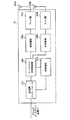
ここで、図11を参照し、本実施の形態に係る基地局装置20のベースバンド信号処理部208の構成について説明する。図11は、本実施の形態に係る基地局装置20のベースバンド信号処理部208の機能ブロック図である。なお、図11においては、説明の便宜上、スケジューラ234等の構成を含めている。
Here, the configuration of baseband
受信信号に含まれる参照信号(品質測定用参照信号)は、チャネル品質測定部221に入力される。チャネル品質測定部221は、移動局装置10から受信した参照信号の受信状態に基づいて上りリンクのチャネル品質情報(CQI)を測定する。一方、ベースバンド信号処理部208に入力した受信信号は、受信信号に付加されたサイクリックプレフィックスがCP(Cyclic Prefix)除去部222a、222bで除去された後、高速フーリエ変換部224a、224bでフーリエ変換されて周波数領域の情報に変換される。なお、シンボル同期部223a、223bは、受信信号に含まれる参照信号から同期タイミングを推定し、その推定結果をCP除去部222a、222bに通知する。
The reference signal (quality measurement reference signal) included in the received signal is input to the channel
周波数領域の情報に変換された受信信号は、サブキャリアデマッピング部225a、225bにて周波数領域でデマッピングされる。サブキャリアデマッピング部225a、225bは、移動局装置10でのマッピングに対応してデマッピングする。ここでは、上りリンクで受信した受信信号のうち、サブキャリアデマッピング部225bに入力される受信信号は、2つの上りデータコードワード#2、#3がコンバインされているものとする。周波数領域等化部226は、チャネル推定部227から与えられるチャネル推定値に基づいて受信信号を等化する。チャネル推定部227は、受信信号に含まれる参照信号からコンポーネントキャリア毎にチャネル状態を推定し、周波数領域等化部226は、コンポーネントキャリア毎に受信信号(コードワード)を等化する。
The received signal converted into frequency domain information is demapped in the frequency domain by
逆離散フーリエ変換部(IDFT)228a、228b、228cは、受信信号を逆離散フーリエ変換して、周波数領域の信号を時間領域の信号に戻す。データ復調部229a、229b、229c及びデータ復号部230a、230b、230cは、コンポーネントキャリア毎の伝送フォーマット(符号化率、変調方式)に基づいて上りユーザデータを再生する。これにより、第1のトランスポートブロックに対応するコードワード#1の送信データ、第2のトランスポートブロックに対応するコードワード#2の送信データ、第3のトランスポートブロックに対応するコードワード#3の送信データが再生される。
The inverse discrete Fourier transform units (IDFT) 228a, 228b, 228c perform inverse discrete Fourier transform on the received signal to return the frequency domain signal to the time domain signal. The data demodulation
再生されたコードワード#1、#2、#3の送信データは、再送情報チャネル選択部233に出力される。再送情報チャネル選択部233は、コードワード#1、#2、#3の送信データにおける再送の要否(ACK/NACK)を判定する。そして、コードワード#1、#2、#3の送信データにおける再送の要否に基づいて、NDI情報やRV情報などの再送関連情報を生成する。また、再送情報チャネル選択部233は、再送情報を送信するチャネル(PHICH又はPDCCH(UL grant))を選択する。
The reproduced transmission data of
スケジューラ234は、チャネル品質測定部221から与えられるチャネル品質情報(CQI)と、後述するプリコーディングウェイト・ランク数選択部235から与えられるPMI情報及びRI情報とに基づいて、上下リンクのリソース割り当て情報を決定する。また、スケジューラ234は、制御部を構成するものであり、移動局装置10に複数のコンポーネントキャリアを割り当て、複数のセルに同時接続するようにセル構成した場合は、移動局装置10に割り当てた複数のコンポーネントキャリアをTAGに分類し、TAG毎の送信タイミングの制御を行う。
Based on channel quality information (CQI) given from the channel
プリコーディングウェイト・ランク数選択部235は、チャネル品質測定部221から与えられるチャネル品質情報(CQI)に基づいて、移動局装置10に割り当てたリソースブロックでの上りリンクの受信品質から当該移動局装置10においてアンテナ毎に送信信号の位相及び又は振幅を制御するためのプリコーディングウェイト(PMI)を決定する。また、プリコーディングウェイト・ランク数選択部235は、チャネル品質測定部221から与えられるチャネル品質情報(CQI)に基づいて、上りリンクにおける空間多重のレイヤ数を示すランク数(RI)を決定する。
Based on the channel quality information (CQI) given from the channel
MCS選択部236は、チャネル品質測定部221から与えられるチャネル品質情報(CQI)に基づいて、変調方式・チャネル符号化率(MCS)を選択する。
The
個別ユーザデータ生成部237は、アクセスゲートウェイ装置等の上位局装置30より入力されるユーザデータから、スケジューラ234から与えられるリソース割り当て情報に従って移動局装置10毎の個別の下り送信データ(個別ユーザデータ)を生成する。
The individual user
UL grant情報生成部238は、再送情報チャネル選択部233から与えられるACK/NACK情報及び再送関連情報(NDI情報、RV情報)、スケジューラ234から与えられるリソース割り当て情報、プリコーディングウェイト・ランク数選択部233から与えられるPMI及びRI情報、並びに、MCS選択部236から与えられるMCS情報に基づいて、上述したUL grantを含むDCIフォーマットを生成する。
The UL grant
PHICH信号生成部239は、再送情報チャネル選択部233から与えられるACK/NACK情報及び再送関連情報(NDI情報、RV情報)に基づいて、移動局装置10に対してトランスポートブロックを再送すべきか否かを示すためのハイブリッドARQの確認応答を含むPHICH信号を生成する。
Whether or not the PHICH
PDSCH信号生成部240は、個別ユーザデータ生成部237で生成された下り送信データ(個別ユーザデータ)に基づいて、物理下り共有チャネル(PDSCH)で実際に送信する下り送信データを生成する。PDCCH信号生成部241は、UL grant情報生成部238で生成されたてUL grantを含むDCIフォーマットに基づいて、物理下り制御チャネルに多重するPDCCH信号を生成する。
The PDSCH
これらのPHICH信号生成部239、PDSCH信号生成部240及びPDCCH信号生成部241で生成されたPHICH信号、PDSCH信号及びPDCCH信号がOFDM変調部242に入力される。OFDM変調部242は、これらのPHICH信号、PDSCH信号及びPDCCH信号を含んだ2系列の信号にOFDM変調処理を施し、送受信部206a、206bへ送出する。
The PHICH signal, the PDSCH signal, and the PDCCH signal generated by the PHICH
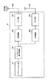
次に、図12を参照しながら、本実施の形態に係る移動局装置10の構成について説明する。本実施の形態に係る移動局装置10は、図12に示すように、MIMO伝送のための2つの送受信アンテナ102a、102bと、アンプ部104a、104bと、送受信部106a、106bと、ベースバンド信号処理部108と、アプリケーション部110とを備えている。なお、送受信部106は、上りリンクの物理チャネル信号を送信する送信部を構成する。
Next, the configuration of
下りリンクのデータについては、2つの送受信アンテナ102a、102bで受信された無線周波数信号がアンプ部104a、104bで増幅され、送受信部106a、106bで周波数変換されてベースバンド信号に変換される。このベースバンド信号は、ベースバンド信号処理部108でFFT処理や、誤り訂正復号、再送制御の受信処理等がなされる。このような下りリンクのデータのうち、下りリンクのユーザデータは、アプリケーション部110に転送される。アプリケーション部110は、物理レイヤやMACレイヤより上位のレイヤに関する処理等を行う。また、下りリンクのデータのうち、報知情報も、アプリケーション部110に転送される。
For downlink data, radio frequency signals received by the two transmission /
一方、上りリンクのユーザデータについては、アプリケーション部110からベースバンド信号処理部108に入力される。ベースバンド信号処理部108では、再送制御(ハイブリッドARQ:Hybrid ARQ)の送信処理や、チャネル符号化、プリコーディング、DFT処理、IFFT処理等が行われて送受信部106a、106bに転送される。送受信部106a、106bでは、ベースバンド信号処理部108から出力されたベースバンド信号を無線周波数帯に変換する周波数変換処理が施され、その後、アンプ部104a、104bで増幅されて送受信アンテナ102a、102bより送信される。
On the other hand, uplink user data is input from the
図13は、移動局装置10が有するベースバンド信号処理部108の構成を示すブロック図である。ベースバンド信号処理部108は、レイヤ1処理部1081と、MAC処理部1082と、RLC処理部1083と、送信電力制御部1084とから主に構成されている。
FIG. 13 is a block diagram illustrating a configuration of the baseband
レイヤ1処理部1081は、主に物理レイヤに関する処理を行う。レイヤ1処理部1081は、例えば、下りリンクで受信した信号に対して、チャネル復号化、離散フーリエ変換、周波数デマッピング、逆フーリエ変換、データ復調などの処理を行う。また、レイヤ1処理部1081は、上りリンクで送信する信号に対して、チャネル符号化、データ変調、周波数マッピング、逆フーリエ変換(IFFT)などの処理を行う。
The
MAC処理部1082は、下りリンクで受信した信号に対するMACレイヤでの再送制御(ハイブリッドARQ)、下りスケジューリング情報の解析(PDSCHの伝送フォーマットの特定、PDSCHのリソースブロックの特定)などを行う。また、MAC処理部1082は、上りリンクで送信する信号に対するMAC再送制御、上りスケジューリング情報の解析(PUSCHの伝送フォーマットの特定、PUSCHのリソースブロックの特定)などの処理を行う。
The
RLC処理部1083は、下りリンクで受信したパケット/上りリンクで送信するパケットに対して、パケットの分割、パケットの結合、RLCレイヤでの再送制御などを行う。
The
送信電力制御部1084は、電力制御部を構成するものであり、MTAが適用された状態において、CC毎の送信電力が上限値を超える場合、全てのCCのトータル送信電力が上限値を超える場合には、上述したいずれかの方法によりTAG(セル、CC、上り物理チャネル又はパケット)に対してパワースケーリングを適用して送信電力を減少させる。
The transmission
上述したように、送信電力制御部1084は、FO区間の物理チャネルを優先してパワースケーリングを行う。例えば、送信電力制御部1084は、PO区間の物理チャネルより優先してパワースケーリングを行うことができる。FO区間の物理チャネルを優先してパワースケーリングを行う際、3つ以上のCCに同時接続するように構成されている場合、送信電力制御部1084は、パワースケーリングを適用する複数(2つ以上)のCCをランダムに選択でき、或いは、パワースケーリングを適用するCCを巡回的に選択できる。
As described above, the transmission
また、FO区間の物理チャネルを優先してパワースケーリングを行う際、送信電力制御部1084は、予め定められた物理チャネル毎の優先度に基づいてパワースケーリングを適用することができる。物理チャネル毎の優先度は、パワースケーリングを適用する優先度を示す。例えば、SRS、PUSCH、PUCCH及びPRACHの順序に定めることができ、SRSにおける優先度を最も高くする一方、PRACHにおける優先度を最も低くすることができる。例えば、送信電力制御部1084は、図7に示す電力補正対象テーブルを利用し、物理チャネル毎の優先度に基づいてパワースケーリングを行うことができる。さらに、電力補正が適用される複数の物理チャネルセットが存在する場合、送信電力制御部1084は、制御信号を含まない物理チャネルが含まれる物理チャネルセットを優先して電力補正の適用対象に選択できる。
In addition, when performing power scaling by giving priority to the physical channel in the FO section, the transmission
一方、変形例1が適用される場合、送信電力制御部1084は、予め定められた物理チャネル毎の優先度に基づいてパワースケーリングを適用する。例えば、送信電力制御部1084は、図7に示す電力補正対象テーブルを利用し、物理チャネル毎の優先度に基づいてパワースケーリングを行うことができる。さらに、電力補正が適用される複数の物理チャネルセットが存在する場合、送信電力制御部1084は、制御信号を含まない物理チャネルが含まれる物理チャネルセットを優先してパワースケーリングの適用対象に選択できる。
On the other hand, when the first modification is applied, the transmission
また、変形例2が適応される場合、送信電力制御部1084は、Scellに対応する物理チャネルを、Pcellに対応する物理チャネルよりも優先してパワースケーリングを行う。なお、変形例1と変形例2とを組み合わせる場合、送信電力制御部1084は、予め定められた物理チャネル毎の優先度だけでなく、TAGが割り当てられるCC(セル)の種別(Pcell又はScell)も判定してパワースケーリングの適用対象を選択する。
Further, when the second modification is applied, the transmission
さらに、変形例3が適用される場合、送信電力制御部1084は、各種の信号重複区間で送信される物理チャネルのうち、特定の信号重複区間で送信される特定の物理チャネルのみにパワースケーリングを行う。例えば、送信電力制御部1084は、PO区間で送信されるPUSCHなどに限ってパワースケーリングを行うことができる。さらに、変形例4が適用される場合、送信電力制御部1084は、信号重複区間の種別に関わらず、時系列的に信号重複区間のパワースケーリングを行う。この場合、例えば、予め定められた物理チャネル毎の優先度に基づいてパワースケーリングを適用することができる。
Further, when the third modification is applied, the transmission
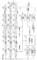
図14を参照し、移動局装置10のベースバンド信号処理部108におけるレイヤ1処理部1081の構成について説明する。同図に示すように、送受信部106a、106bから出力される受信信号がOFDM復調部111で復調される。OFDM復調部111で復調された下りリンクの受信信号のうち、PDSCH信号は下りPDSCH復号部112に入力され、PHICH信号は下りPHICH復号部113に入力される、PDCCH信号は下りPDCCH復号部114に入力される。下りPDSCH復号部112は、PDSCH信号を復号し、PDSCH送信データを再生する。下りPHICH復号部113は、下りリンクのPHICH信号を復号する。下りPDCCH復号部114は、PDCCH信号を復号する。PDCCH信号には、UL grantを含むDCIフォーマットが含まれる。
The configuration of the
データ新規送信/再送判定部115は、下りPHICH復号部113により復号されたPHICH信号にハイブリッドARQの確認応答(ACK/NACK)が含まれる場合、そのハイブリッドARQの確認応答(ACK/NACK)に基づいて、新規のデータ送信又は再送を判定する。また、PDCCH信号のUL grantにハイブリッドARQの確認応答(ACK/NACK)が含まれる場合、そのハイブリッドARQの確認応答(ACK/NACK)に基づいて、新規のデータ送信又は再送を判定する。これらの判定結果を新規送信データバッファ部116及び再送データバッファ部117に通知する。
When the PHICH signal decoded by downlink
新規送信データバッファ部116は、アプリケーション部110から入力された上りリンクの送信データをバッファリングしている。再送データバッファ部117は、新規送信データバッファ部116から出力された送信データをバッファリングする。データ新規送信/再送判定部115から新規のデータ送信である旨の判定結果が通知されると、新規送信データバッファ部116内の送信データから上り送信データが生成される。一方、データ新規送信/再送判定部115からデータ再送である旨の判定結果が通知されると、再送データバッファ部117内の送信データから上り送信データが生成される。
The new transmission
生成された上り送信データは、図示しない直並列変換部に入力される。この直並列変換部においては、上り送信データが、上りリンクのランク数に応じてコードワード数分に直並列変換される。なお、コードワード(符号語)とは、チャネル符号化の符号化単位を示しており、その数(コードワード数)は、ランク数及び又は送信アンテナ数により一意に決定される。ここでは、コードワード数が3つに決定された場合について示している。なお、コードワード数とレイヤ数(ランク数)とは必ずしも等しくはならない。上りコードワード#1送信データ、上りコードワード#2送信データ、上りコードワード#3送信データは、データ符号化部118a、118b、118cに入力される。
The generated uplink transmission data is input to a serial / parallel converter (not shown). In this serial-parallel conversion unit, uplink transmission data is serial-parallel converted into the number of codewords according to the number of uplink ranks. The code word (code word) indicates a coding unit of channel coding, and the number (code word number) is uniquely determined by the number of ranks and / or the number of transmission antennas. Here, a case where the number of code words is determined to be three is shown. Note that the number of codewords and the number of layers (number of ranks) are not necessarily equal.
データ符号化部118aでは、上りコードワード#1送信データが符号化される。データ符号化部118aで符号化された上りコードワード#1送信データは、データ変調部119aで変調され、多重部120aで多重された後、逆フーリエ変換部(DFT)121aで逆フーリエ変換されて時系列の情報が周波数領域の情報に変換される。なお、データ符号化部118a、データ変調部119aは、下りPDCCH復号部114からのMCS情報に基づいて、上りコードワード#1送信データの符号化及び変調処理を行う。サブキャリアマッピング部122aでは、下りPDCCH復号部114からのスケジューリング情報(リソース割り当て情報)に基づいて周波数領域でのマッピングを行う。なお、データ符号化部118b、118cからサブキャリアマッピング部122b、122cにおいても、上りコードワード#2、#3に対して上りコードワード#1と同様の処理が行われる。そして、マッピング後の上りコードワード#1送信データが逆高速フーリエ変換部(IFFT)123a、123b、123cにて送信信号を逆高速フーリエ変換して周波数領域の信号を時間領域の信号に変換する。そして、サイクリックプレフィックス(CP)付与部124a、124b、124cにて送信信号にサイクリックプレフィックスを付与する。ここで、サイクリックプレフィックスは、マルチパス伝搬遅延及び基地局装置20における複数ユーザ間の受信タイミングの差を吸収するためのガードインターバルとして機能する。
In the data encoding unit 118a, the
今、セルC1にCC#1が割り当てられ、セルC2に2つのCC#2及びCC#3が割り当てられていて、CC#1がTAG#1に分類され、CC#2及びCC#3がTAG#2に分類されているものとする。そして、セルC1とセルC2に接続している移動局装置10に対してMTAが適用されて、TAG#1が送信タイミングT1に設定され、TAG#2が送信タイミングT2に設定されているとする。本実施の形態では、上りデータ(コードワード#1)がセルC1の上りリンクで送信され、上りデータ(コードワード#2、#3)がセルC2の上りリンクで送信されるものとする。
Now,
以上の状況下において、セルC1の上りリンクデータである送信信号(コードワード#1)は、MTA処理部125aにて送信タイミングがタイミングT1に制御される。また、セルC2の上りリンクデータである送信信号(コードワード#2)は、MTA処理部125bにて送信タイミングがタイミングT2に制御され、送信信号(コードワード#3)は、MTA処理部125cにて送信タイミングがタイミングT2に制御される。セルC2の上りリンクデータである送信信号(コードワード#2)及び送信信号(コードワード#3)は共にタイミングT2に制御され、さらにCombiner126でコンバインされる。
Under the above circumstances, the transmission timing of the transmission signal (codeword # 1), which is the uplink data of the cell C1, is controlled by the
このように本実施の形態に係る移動局装置10においては、TAG毎に制御された送信タイミングにて上りリンクの物理チャネルを送信する場合に、コンポーネントキャリア(CC)を跨いで同一サブフレーム番号の物理チャネルが重複するFO区間の物理チャネルを優先してパワースケーリングを行う。これにより、PO区間やSO区間の物理チャネルに優先してFO区間の物理チャネルを電力補正できるので、PO区間等の物理チャネルを優先して電力補正を行う場合に発生する上りリンク伝送品質の劣化を最小化できる。この結果、上りリンク伝送品質の劣化を抑制しつつ、上りリンクの送信電力が上限値を超える信号重複区間におけるパワースケーリングを適用することが可能となる。
As described above, in the
以上、上述の実施形態を用いて本発明について詳細に説明したが、当業者にとっては、本発明が本明細書中に説明した実施形態に限定されるものではないということは明らかである。本発明は、特許請求の範囲の記載により定まる本発明の趣旨及び範囲を逸脱することなく修正及び変更態様として実施することができる。従って、本明細書の記載は、例示説明を目的とするものであり、本発明に対して何ら制限的な意味を有するものではない。 Although the present invention has been described in detail using the above-described embodiments, it is obvious to those skilled in the art that the present invention is not limited to the embodiments described in this specification. The present invention can be implemented as modified and changed modes without departing from the spirit and scope of the present invention defined by the description of the scope of claims. Therefore, the description of the present specification is for illustrative purposes and does not have any limiting meaning to the present invention.
1 移動通信システム
10、10A,10B 移動局装置
102a、102b 送受信アンテナ
104a、104b アンプ部
106a、106b 送受信部
108 ベースバンド処理部
1081 レイヤ1処理部
1084 送信電力制御部
110 アプリケーション部
111 OFDM復調部
112 下りPDSCH復号部
113 下りPHICH復号部
114 下りPDCCH復号部
115 データ新規送信/再送判定部
116 新規送信データバッファ部
117 再送データバッファ部
125a、125b、125c MTA処理部
20、20A,20B 基地局装置
202a、202b 送受信アンテナ
204a、204b アンプ部
206a、206b 送受信部
208 ベースバンド信号処理部
210 呼処理部
212 伝送路インターフェース
221 チャネル品質測定部
233 再送情報チャネル選択部
234 スケジューラ
235 プリコーディングウェイト・ランク数選択部
236 MCS選択部
237 個別ユーザデータ生成部
238 UL grant情報生成部
239 PHICH信号生成部
240 PDSCH信号生成部
241 PDCCH信号生成部
242 OFDM変調部
30 上位局装置
DESCRIPTION OF
Claims (9)
複数のコンポーネントキャリアが複数のタイミンググループに分類されていて、タイミンググループ毎に制御された送信タイミングにて上りリンクの物理チャネルを送信する送信部と、上りリンクの送信タイミングがタイミンググループ単位で制御されている場合、コンポーネントキャリアを跨いで同一サブフレーム番号の物理チャネルが重複するフルオーバーラップ区間の物理チャネルを優先して電力補正する電力制御部と、
を具備したことを特徴とするユーザ端末。 In a user terminal capable of communicating with a plurality of radio base stations via a plurality of component carriers on a radio communication system capable of configuring a system band with a plurality of component carriers,
A plurality of component carriers are classified into a plurality of timing groups, and a transmission unit that transmits an uplink physical channel at a transmission timing controlled for each timing group, and uplink transmission timing is controlled in units of timing groups. A power control unit that preferentially power corrects the physical channel of the full overlap section where physical channels of the same subframe number overlap across component carriers, and
A user terminal comprising:
それぞれセルを形成する複数の基地局装置と、複数のコンポーネントキャリアを介して1つ又は複数の前記基地局装置と通信可能なユーザ端末とを備え、
前記基地局装置は、1つ又は複数のコンポーネントキャリアが分類されたタイミンググループ毎に上りリンクの送信タイミングを制御する制御部と、上りリンクを介して前記ユーザ端末から物理チャネルを受信する受信部とを具備し、
前記ユーザ端末は、タイミンググループ毎に制御された送信タイミングにて上りリンクの物理チャネルを送信する送信部と、上りリンクの送信タイミングがタイミンググループ単位で制御されている場合、コンポーネントキャリアを跨いで同一サブフレーム番号の物理チャネルが重複するフルオーバーラップ区間の物理チャネルを優先して電力補正する電力制御部とを具備することを特徴とする無線通信システム。 In a wireless communication system in which a system band can be configured with a plurality of component carriers,
A plurality of base station devices each forming a cell, and a user terminal capable of communicating with one or a plurality of the base station devices via a plurality of component carriers,
The base station apparatus includes a control unit that controls uplink transmission timing for each timing group into which one or more component carriers are classified, and a receiving unit that receives a physical channel from the user terminal via the uplink. Comprising
The user terminal transmits the uplink physical channel at the transmission timing controlled for each timing group, and when the uplink transmission timing is controlled in units of timing groups, it is the same across the component carriers A wireless communication system, comprising: a power control unit that preferentially corrects a power of a physical channel in a full overlap section in which physical channels of subframe numbers overlap.
前記無線通信システムは、それぞれセルを形成する複数の基地局装置と、複数のコンポーネントキャリアを介して1つ又は複数の前記基地局装置と通信可能なユーザ端末と、を備え、
前記ユーザ端末において、タイミンググループ毎に制御された送信タイミングにて上りリンクの物理チャネルを送信するステップと、前記ユーザ端末において、上りリンクの送信タイミングがタイミンググループ単位で制御されている場合、コンポーネントキャリアを跨いで同一サブフレーム番号の物理チャネルが重複するフルオーバーラップ区間の物理チャネルを優先して電力補正するステップとを具備することを特徴とする無線通信方法。 In a wireless communication method in a wireless communication system in which a plurality of cells are formed,
The wireless communication system includes a plurality of base station apparatuses each forming a cell, and user terminals capable of communicating with one or a plurality of the base station apparatuses via a plurality of component carriers,
In the user terminal, a step of transmitting an uplink physical channel at transmission timing controlled for each timing group; and in the user terminal, when uplink transmission timing is controlled in units of timing groups, a component carrier And preferentially correcting the power of a physical channel in a full overlap section in which physical channels with the same subframe number overlap across the same.
Priority Applications (6)
| Application Number | Priority Date | Filing Date | Title |
|---|---|---|---|
| JP2012242406A JP2014093628A (en) | 2012-11-02 | 2012-11-02 | User terminal, radio communication system, and radio communication method |
| EP13852037.4A EP2916598A4 (en) | 2012-11-02 | 2013-08-29 | User terminal, wireless communication system, and wireless communication method |
| CN201380056746.8A CN104756561A (en) | 2012-11-02 | 2013-08-29 | User terminal, wireless communication system, and wireless communication method |
| PCT/JP2013/073161 WO2014069085A1 (en) | 2012-11-02 | 2013-08-29 | User terminal, wireless communication system, and wireless communication method |
| MX2015005468A MX2015005468A (en) | 2012-11-02 | 2013-08-29 | User terminal, wireless communication system, and wireless communication method. |
| US14/439,381 US20150312866A1 (en) | 2012-11-02 | 2013-08-29 | User terminal, radio communication system and radio communication method |
Applications Claiming Priority (1)
| Application Number | Priority Date | Filing Date | Title |
|---|---|---|---|
| JP2012242406A JP2014093628A (en) | 2012-11-02 | 2012-11-02 | User terminal, radio communication system, and radio communication method |
Publications (2)
| Publication Number | Publication Date |
|---|---|
| JP2014093628A true JP2014093628A (en) | 2014-05-19 |
| JP2014093628A5 JP2014093628A5 (en) | 2015-11-05 |
Family
ID=50627006
Family Applications (1)
| Application Number | Title | Priority Date | Filing Date |
|---|---|---|---|
| JP2012242406A Pending JP2014093628A (en) | 2012-11-02 | 2012-11-02 | User terminal, radio communication system, and radio communication method |
Country Status (6)
| Country | Link |
|---|---|
| US (1) | US20150312866A1 (en) |
| EP (1) | EP2916598A4 (en) |
| JP (1) | JP2014093628A (en) |
| CN (1) | CN104756561A (en) |
| MX (1) | MX2015005468A (en) |
| WO (1) | WO2014069085A1 (en) |
Cited By (4)
| Publication number | Priority date | Publication date | Assignee | Title |
|---|---|---|---|---|
| WO2015194634A1 (en) * | 2014-06-20 | 2015-12-23 | シャープ株式会社 | Terminal device, base-station device, and communication method |
| JP2017188874A (en) * | 2016-04-01 | 2017-10-12 | エヌエックスピー ビー ヴィNxp B.V. | Signal processing circuits |
| JP2017530648A (en) * | 2014-10-02 | 2017-10-12 | クゥアルコム・インコーポレイテッドQualcomm Incorporated | Techniques for managing power on uplink component carriers transmitted over a shared radio frequency spectrum band |
| WO2018083863A1 (en) * | 2016-11-02 | 2018-05-11 | 株式会社Nttドコモ | User device |
Families Citing this family (9)
| Publication number | Priority date | Publication date | Assignee | Title |
|---|---|---|---|---|
| WO2015126289A1 (en) * | 2014-02-19 | 2015-08-27 | Telefonaktiebolaget L M Ericsson (Publ) | Data transmission over a reduced number of physical antennas |
| US10959193B2 (en) * | 2014-08-04 | 2021-03-23 | Sharp Kabushiki Kaisha | Terminal device, base station device, and method |
| US20160192390A1 (en) * | 2014-12-30 | 2016-06-30 | Electronics And Telecommunications Research Institute | Method for transmitting data based on limited contention |
| WO2017047445A1 (en) * | 2015-09-18 | 2017-03-23 | シャープ株式会社 | Terminal device, base station device, communication method, and integrated circuit |
| WO2017176183A1 (en) * | 2016-04-07 | 2017-10-12 | Telefonaktiebolaget Lm Ericsson (Publ) | Radio-network node, wireless device and methods performed therein |
| JP7297663B2 (en) * | 2017-05-01 | 2023-06-26 | パナソニック インテレクチュアル プロパティ コーポレーション オブ アメリカ | Terminal and communication method |
| WO2019123837A1 (en) * | 2017-12-21 | 2019-06-27 | ソニー株式会社 | Transmission control device, transmission control method, reception control device, reception control method, and signal transmission system |
| WO2020037457A1 (en) | 2018-08-20 | 2020-02-27 | Qualcomm Incorporated | Synchronized scheduling for carrier aggregation |
| US20230232393A1 (en) * | 2020-08-07 | 2023-07-20 | Qualcomm Incorporated | Uplink transmit switch scheduling of carrier aggregation |
Family Cites Families (6)
| Publication number | Priority date | Publication date | Assignee | Title |
|---|---|---|---|---|
| CN1189939A (en) * | 1996-04-26 | 1998-08-05 | 摩托罗拉公司 | Multiple user communication system, device and method with overlapping uplink carrier spectra |
| CN101578790B (en) * | 2007-03-20 | 2012-10-31 | Lg电子株式会社 | Method of controlling transmit power in wireless communication system |
| KR101790593B1 (en) * | 2010-04-01 | 2017-10-26 | 선 페이턴트 트러스트 | Transmit power control for physical random access channels |
| KR101306377B1 (en) * | 2011-09-29 | 2013-09-09 | 엘지전자 주식회사 | Method and apparatus for uplink transmission |
| CN102572967B (en) * | 2012-01-13 | 2014-07-30 | 电信科学技术研究院 | Method, system and equipment for transmitting and receiving uplink information |
| US8958342B2 (en) * | 2012-04-17 | 2015-02-17 | Ofinno Technologies, Llc | Uplink transmission power in a multicarrier wireless device |
-
2012
- 2012-11-02 JP JP2012242406A patent/JP2014093628A/en active Pending
-
2013
- 2013-08-29 WO PCT/JP2013/073161 patent/WO2014069085A1/en active Application Filing
- 2013-08-29 US US14/439,381 patent/US20150312866A1/en not_active Abandoned
- 2013-08-29 CN CN201380056746.8A patent/CN104756561A/en active Pending
- 2013-08-29 EP EP13852037.4A patent/EP2916598A4/en not_active Withdrawn
- 2013-08-29 MX MX2015005468A patent/MX2015005468A/en unknown
Non-Patent Citations (3)
| Title |
|---|
| JPN6015040972; Panasonic: 'UE behavior for power limitation in multiple TA' 3GPP TSG-RAN WG1 Meeting #69 R1-122177, 20120525, 3GPP * |
| JPN6016000174; ZTE: 'Consideration on remaining issues related to multiple TA' 3GPP TSG-RAN WG1#69 R1-122119, 20120525, 3GPP * |
| JPN6016000175; LG Electronics: 'Power limitation in multiple TA' 3GPP TSG-RAN WG1#68bis R1-121426, 20120330, 3GPP * |
Cited By (11)
| Publication number | Priority date | Publication date | Assignee | Title |
|---|---|---|---|---|
| WO2015194634A1 (en) * | 2014-06-20 | 2015-12-23 | シャープ株式会社 | Terminal device, base-station device, and communication method |
| JPWO2015194634A1 (en) * | 2014-06-20 | 2017-04-20 | シャープ株式会社 | Terminal apparatus, base station apparatus, and communication method |
| JP2017530648A (en) * | 2014-10-02 | 2017-10-12 | クゥアルコム・インコーポレイテッドQualcomm Incorporated | Techniques for managing power on uplink component carriers transmitted over a shared radio frequency spectrum band |
| US10980045B2 (en) | 2014-10-02 | 2021-04-13 | Qualcomm Incorporated | Techniques for managing power on an uplink component carrier transmitted over a shared radio frequency spectrum band |
| US11889499B2 (en) | 2014-10-02 | 2024-01-30 | Qualcomm Incorporated | Techniques for managing power on an uplink component carrier transmitted over a shared radio frequency spectrum band |
| JP2017188874A (en) * | 2016-04-01 | 2017-10-12 | エヌエックスピー ビー ヴィNxp B.V. | Signal processing circuits |
| JP7079566B2 (en) | 2016-04-01 | 2022-06-02 | エヌエックスピー ビー ヴィ | Signal processing circuit |
| WO2018083863A1 (en) * | 2016-11-02 | 2018-05-11 | 株式会社Nttドコモ | User device |
| CN109845319A (en) * | 2016-11-02 | 2019-06-04 | 株式会社Ntt都科摩 | User apparatus |
| US10856179B2 (en) | 2016-11-02 | 2020-12-01 | Ntt Docomo, Inc. | User equipment |
| CN109845319B (en) * | 2016-11-02 | 2022-08-12 | 株式会社Ntt都科摩 | User device |
Also Published As
| Publication number | Publication date |
|---|---|
| CN104756561A (en) | 2015-07-01 |
| EP2916598A4 (en) | 2016-06-08 |
| WO2014069085A1 (en) | 2014-05-08 |
| MX2015005468A (en) | 2015-07-23 |
| US20150312866A1 (en) | 2015-10-29 |
| EP2916598A1 (en) | 2015-09-09 |
Similar Documents
| Publication | Publication Date | Title |
|---|---|---|
| WO2014069085A1 (en) | User terminal, wireless communication system, and wireless communication method | |
| WO2014050351A1 (en) | Wireless communication system, base station, user equipment, and wireless communication method | |
| JP6725497B2 (en) | User terminal, wireless base station and wireless communication method | |
| JP5606836B2 (en) | Wireless communication system and mobile terminal device | |
| US8982817B2 (en) | Radio communication system, base station apparatus and user terminal | |
| US20160044656A1 (en) | Systems and methods for uplink signaling using time-frequency resources | |
| US9137803B2 (en) | Radio communication control method, base station apparatus and mobile terminal apparatus | |
| JP5189144B2 (en) | COMMUNICATION CONTROL METHOD, BASE STATION DEVICE, AND MOBILE STATION DEVICE | |
| JP4672063B2 (en) | Mobile station, communication control method, and mobile communication system | |
| US9439182B2 (en) | Radio communication system, radio base station apparatus, user terminal and radio communication method | |
| WO2013069733A1 (en) | Wireless communication system, radio base station apparatus, user terminal, and wireless communication method | |
| JP2011238980A (en) | Base station apparatus, mobile terminal device, and communication control method | |
| JP5298086B2 (en) | Base station apparatus, mobile terminal apparatus and communication control method | |
| JP5820246B2 (en) | Radio communication system, radio communication method, radio base station apparatus, and user terminal | |
| WO2014021009A1 (en) | Wireless communication system, wireless base stations and retransmission control method | |
| WO2011125997A1 (en) | User terminal and base station device | |
| WO2011052777A1 (en) | Mobile terminal device, wireless base station device, and wireless communication method | |
| JP6360142B2 (en) | User terminal and wireless communication method | |
| WO2016163501A1 (en) | User terminal, wireless base station, and wireless communication method |
Legal Events
| Date | Code | Title | Description |
|---|---|---|---|
| A521 | Request for written amendment filed |
Free format text: JAPANESE INTERMEDIATE CODE: A523 Effective date: 20150911 |
|
| A621 | Written request for application examination |
Free format text: JAPANESE INTERMEDIATE CODE: A621 Effective date: 20150911 |
|
| A871 | Explanation of circumstances concerning accelerated examination |
Free format text: JAPANESE INTERMEDIATE CODE: A871 Effective date: 20150911 |
|
| A975 | Report on accelerated examination |
Free format text: JAPANESE INTERMEDIATE CODE: A971005 Effective date: 20151007 |
|
| A131 | Notification of reasons for refusal |
Free format text: JAPANESE INTERMEDIATE CODE: A131 Effective date: 20151013 |
|
| A521 | Request for written amendment filed |
Free format text: JAPANESE INTERMEDIATE CODE: A523 Effective date: 20151211 |
|
| A02 | Decision of refusal |
Free format text: JAPANESE INTERMEDIATE CODE: A02 Effective date: 20160112 |