JP7621679B2 - Gaming Machines - Google Patents
Gaming Machines Download PDFInfo
- Publication number
- JP7621679B2 JP7621679B2 JP2023174097A JP2023174097A JP7621679B2 JP 7621679 B2 JP7621679 B2 JP 7621679B2 JP 2023174097 A JP2023174097 A JP 2023174097A JP 2023174097 A JP2023174097 A JP 2023174097A JP 7621679 B2 JP7621679 B2 JP 7621679B2
- Authority
- JP
- Japan
- Prior art keywords
- time
- special symbol
- saving
- game state
- showing
- Prior art date
- Legal status (The legal status is an assumption and is not a legal conclusion. Google has not performed a legal analysis and makes no representation as to the accuracy of the status listed.)
- Active
Links
Images


Classifications
-
- Y—GENERAL TAGGING OF NEW TECHNOLOGICAL DEVELOPMENTS; GENERAL TAGGING OF CROSS-SECTIONAL TECHNOLOGIES SPANNING OVER SEVERAL SECTIONS OF THE IPC; TECHNICAL SUBJECTS COVERED BY FORMER USPC CROSS-REFERENCE ART COLLECTIONS [XRACs] AND DIGESTS
- Y02—TECHNOLOGIES OR APPLICATIONS FOR MITIGATION OR ADAPTATION AGAINST CLIMATE CHANGE
- Y02E—REDUCTION OF GREENHOUSE GAS [GHG] EMISSIONS, RELATED TO ENERGY GENERATION, TRANSMISSION OR DISTRIBUTION
- Y02E60/00—Enabling technologies; Technologies with a potential or indirect contribution to GHG emissions mitigation
- Y02E60/10—Energy storage using batteries
Landscapes
- Pinball Game Machines (AREA)
Description
本発明は、例えばパチンコ機などの遊技機に関する。 The present invention relates to gaming machines, such as pachinko machines.
従来、例えばパチンコ機などの遊技機は公知となっている。例えば、特許文献1に記載
の如くである。
2. Description of the Related Art Gaming machines such as pachinko machines have been publicly known in the art, for example as described in Japanese Patent Application Laid-Open No. 2003-233666.
特許文献1には、回転動作を行うことで所定の可動演出を行う可動演出役物を備えた遊
技機が開示されている。
このような遊技機において、遊技の興趣をさらに向上させることが望まれている。 It is desirable to further increase the entertainment value of such gaming machines.
本発明は、上述した課題に鑑みてなされたものであり、遊技の興趣を向上させることが
できる遊技機を提供することを目的とする。
The present invention has been made in consideration of the above-mentioned problems, and has an object to provide a gaming machine that can increase the enjoyment of the game.
本発明の解決しようとする課題は以上の如くであり、次にこの課題を解決するための手
段を説明する。
The problem to be solved by the present invention has been described above, and the means for solving this problem will now be described.
本発明に係る遊技機は、
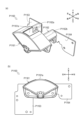
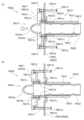
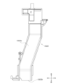
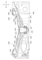
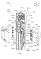
第1の部分(例えば、塔役物P7400等)と、第2の部分(例えば、振分部P7360等)と、第3の部分(例えば、特定領域ユニットP7900等)と、を備えた構造部を有する遊技機であって、
前記第1の部分は、当該第1の部分に供給された遊技球の流路(例えば、通路部P7612等)を備え、
前記第2の部分は、遊技球を前記第1の部分へ誘導する流路(例えば、通路部P7361b等)を備え、
前記第3の部分は、前記第1の部分の流路を通過した遊技球の入賞を検出可能な検出手段(例えば、センサ部P7911a等)を備え、
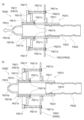
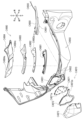
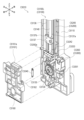
前記第1の部分は、
第1の流路(例えば、特定領域側ガイド部P7424a等)と、
前記第1の流路とは異なる第2の流路(例えば、非特定領域側ガイド部P7424b等)と、
遊技球が転動可能な傾斜する転動面を有し、当該第1の部分に供給された遊技球を前記第1の流路又は前記第2の流路へ振り分け可能な振分部(例えば、第3のステージ部P7700等)と、
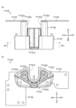
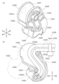
前記振分部を転動する遊技球の転動方向を変更可能な転動障害部と、を備え、
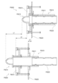
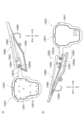
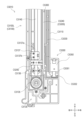
前記転動障害部は、
前記振分部を転動する遊技球と接触可能なように第1の面(例えば、垂直部P7733aの内面等)から突出する複数の第1の突出部(例えば、突出部P7733b等)と、
前記振分部を転動する遊技球と接触可能なように前記第1の面とは異なる第2の面(例えば、第3のステージ本体P7720の転動面等)から突出する複数の第2の突出部(例えば、突起部P7721等)と、を含み、
前記第1の面は、前記振分部を転動する遊技球と接触可能なように前記転動面に対して略垂直方向に形成される面であり、
前記第1の突出部は、前記転動面を転動する遊技球と接触可能なように前記第1の面から前記振分部における遊技球の転動経路上にせり出すように形成され、
前記第1の突出部と前記転動面とは離れて形成され、
前記第1の突出部及び前記第2の突出部は、遊技球が前記第1の突出部の間または前記第2の突出部の間もしくは前記第1の突出部と前記第2の突出部の間を通り前記転動面より下流側に移動可能なように配置され、
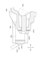
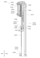
前記振分部が変位することにより、遊技球が前記転動面より下流側に移動可能となり、前記振分部の変位する位置に応じて、
遊技球が前記転動面より下流側に移動せずに前記転動面での転動を継続する場合と、
遊技球が前記転動面より下流側の前記第1の流路に移動する場合と、
遊技球が前記転動面より下流側の前記第2の流路に移動する場合と、がある、
ことを特徴とする。
The gaming machine according to the present invention comprises:
A gaming machine having a structural part including a first part (e.g., a tower role P7400, etc.), a second part (e.g., a distribution part P7360, etc.), and a third part (e.g., a specific area unit P7900, etc.),
The first portion includes a flow path (e.g., a passage portion P7612, etc.) for the game ball supplied to the first portion,
The second portion is provided with a flow path (e.g., a passage portion P7361b, etc.) that guides the game ball to the first portion,
The third section includes a detection means (e.g., a sensor unit P7911a, etc.) capable of detecting the winning of a game ball that has passed through the flow path of the first section,
The first portion is
A first flow path (for example, a specific area side guide portion P7424a, etc.),
A second flow path (for example, a non-specific region side guide portion P7424b, etc.) different from the first flow path;
A distribution section (e.g., a third stage section P7700, etc.) having an inclined rolling surface on which the game balls can roll and capable of distributing the game balls supplied to the first section to the first flow path or the second flow path;
A rolling obstacle portion capable of changing the rolling direction of the game ball rolling in the distribution portion,
The rolling obstacle portion is
A plurality of first protrusions (e.g., protrusions P7733b, etc.) protruding from a first surface (e.g., an inner surface of the vertical portion P7733a, etc.) so as to be able to come into contact with the game balls rolling on the distribution portion;
A plurality of second protrusions (e.g., protrusions P7721, etc.) protruding from a second surface (e.g., a rolling surface of the third stage body P7720, etc.) different from the first surface so as to be able to come into contact with the game balls rolling on the distribution section,
The first surface is a surface formed in a direction substantially perpendicular to the rolling surface so as to be capable of contacting the game ball rolling on the distribution section ,
The first protrusion is formed to protrude from the first surface onto a rolling path of the game ball in the distribution section so as to be able to contact the game ball rolling on the rolling surface,
The first protrusion and the rolling surface are formed apart from each other ,
The first protrusion and the second protrusion are arranged so that a game ball can move downstream from the rolling surface through the first protrusion, the second protrusion, or the first protrusion and the second protrusion;
By displacing the distribution part, the game ball can move downstream from the rolling surface, and depending on the position to which the distribution part is displaced,
A case where the game ball continues to roll on the rolling surface without moving downstream from the rolling surface,
When the game ball moves to the first flow path downstream of the rolling surface,
The game ball may move to the second flow path downstream of the rolling surface.
It is characterized by:
本発明によれば、遊技の興趣を向上させることができる。 The present invention can increase the enjoyment of games.
本発明の実施形態にかかる遊技機の一例として、第1のパチンコ遊技機、第2のパチン
コ遊技機、および第3のパチンコ遊技機を例に挙げて説明する。
As examples of gaming machines according to the embodiments of the present invention, a first pachinko gaming machine, a second pachinko gaming machine, and a third pachinko gaming machine will be described.
なお、この明細書において、特に断りがない限り、パチンコ遊技機の正面側を前方向、
パチンコ遊技機の背面側を後方向、パチンコ遊技機を前方から見たときの左側を左方向、
パチンコ遊技機を前方から見たときの右側を右方向、パチンコ遊技機の上側を上方向、パ
チンコ遊技機の下側を下方向、パチンコ遊技機を前方から見たときの時計回りの方向を右
回り方向、その逆に反時計回りの方向を左回り方向として定義する。
In this specification, unless otherwise specified, the front side of the pachinko machine is referred to as the forward direction.
The rear side of the pachinko machine is called the rear direction, and the left side when looking at the pachinko machine from the front is called the left direction.
The right side when the pachinko game machine is viewed from the front is defined as the right direction, the upper side of the pachinko game machine as the upper direction, the lower side of the pachinko game machine as the lower direction, the clockwise direction when the pachinko game machine is viewed from the front as the rightward direction, and conversely, the counterclockwise direction as the leftward direction.
第1のパチンコ遊技機および第2のパチンコ遊技機は、いずれも、デジパチと称される
所謂1種タイプのパチンコ遊技機である。このうち、第1のパチンコ遊技機は、第1特別
図柄と第2特別図柄とが並行して可変表示されることがなくいずれか一方のみが可変表示
されるパチンコ遊技機である。これに対し、第2のパチンコ遊技機は、第1特別図柄と第
2特別図柄とが並行して可変表示可能なパチンコ遊技機である。
Both the first and second pachinko gaming machines are so-called type one pachinko gaming machines called digital pachinko. Of these, the first pachinko gaming machine is a pachinko gaming machine in which the first special symbol and the second special symbol are not displayed in parallel, but only one of them is displayed in a variable manner. In contrast, the second pachinko gaming machine is a pachinko gaming machine in which the first special symbol and the second special symbol are displayed in parallel.
また、第3のパチンコ遊技機は、デジパチと称される所謂1種タイプの遊技機と羽根モ
ノと称される2種タイプの遊技機とを混合した1種2種混合機と称されるパチンコ遊技機
である。この明細書で説明する第3のパチンコ遊技機も、第1特別図柄および第2特別図
柄を有するが、この明細書では、第1特別図柄と第2特別図柄とが並行して可変表示され
ることがなくいずれか一方のみが可変表示されるものを例に挙げて説明する。ただし、第
1特別図柄と第2特別図柄とが並行して可変表示可能な1種2種混合機のパチンコ遊技機
を排除する趣旨ではない。
The third pachinko machine is a pachinko machine called a 1-type 2-type mixed machine, which is a combination of a so-called 1-type game machine called a digital pachinko machine and a 2-type game machine called a feather game machine. The third pachinko machine described in this specification also has a first special symbol and a second special symbol, but in this specification, the first special symbol and the second special symbol are not displayed in parallel, and only one of them is displayed in a variable manner. However, this is not intended to exclude a 1-type 2-type mixed pachinko machine in which the first special symbol and the second special symbol can be displayed in parallel.
なお、この明細書において、単に「特別図柄」と称するときは、とくに言及しない限り
、第1特別図柄および第2特別図柄の両方を意味するものとする。
In this specification, when the term "special design" is used, it means both the first special design and the second special design, unless otherwise specified.
また、本明細書でいう「可変表示」とは、例えば、図柄が変動して表示される「変動表
示」、および、図柄が停止して表示される「停止表示」等の両方を含む概念であり、変動
表示の開始から停止表示されるまでの動作を1回の「可変表示」と称する。変動表示して
いる図柄が停止表示(以下、「導出」とも称する)されると、後述する特別図柄の当り判
定処理(以下、「特別図柄抽選」もと称する)の結果や普通図柄の当り判定処理(以下、
「普通図柄抽選」とも称する)の結果が確定する。なお、図柄が見掛け上は停止している
ように見えるものの、特別図柄の当り判定処理や普通図柄の当り判定処理の結果が確定し
ない態様(例えば仮停止した態様)で図柄が表示される場合もあるが、このような態様は
上記の変動表示に含まれる。なお、図柄が例えば仮停止した場合であっても、この時点で
は特別図柄の当り判定処理や普通図柄の当り判定処理の結果が確定していないため、再び
図柄を変動表示させることができる。
In addition, the term "variable display" in this specification is a concept that includes both "variable display" where the pattern is displayed by changing, and "static display" where the pattern is displayed by stopping, and the operation from the start of the variable display to the stop display is called one "variable display". When the variable display pattern is stopped (hereinafter also called "deriving"), the result of the special pattern hit determination process (hereinafter also called "special pattern lottery") described later or the normal pattern hit determination process (hereinafter also called "selection of special patterns") is displayed.
The result of the "regular symbol lottery" is determined. Note that although the symbols appear to be stopped, there are cases where the symbols are displayed in a manner in which the results of the special symbol hit determination process and the regular symbol hit determination process are not yet determined (for example, a provisionally stopped state), and such a manner is included in the variable display described above. Note that even if the symbols are temporarily stopped, for example, the results of the special symbol hit determination process and the regular symbol hit determination process are not yet determined at this point, so the symbols can be displayed again in a variable manner.
また、この明細書において、第1のパチンコ遊技機、第2のパチンコ遊技機および第3
のパチンコ遊技機を説明するにあたり、いずれも特別図柄の数が2つ(第1特別図柄、第
2特別図柄)の場合を例に挙げて説明する。ただし、第1のパチンコ遊技機および第3の
パチンコ遊技機については、特別図柄の数は1つであっても良い。
In addition, in this specification, a first pachinko gaming machine, a second pachinko gaming machine and a third pachinko gaming machine
In explaining the pachinko gaming machines, the case where the number of special symbols is two (first special symbol and second special symbol) will be taken as an example. However, the number of special symbols may be one for the first pachinko gaming machine and the third pachinko gaming machine.
[1.第1のパチンコ遊技機]
先ず、第1のパチンコ遊技機について説明する。
[1. The first pachinko game machine]
First, the first pachinko gaming machine will be described.
第1特別図柄と第2特別図柄とが並行して可変表示されることがなくいずれか一方のみ
が可変表示されるパチンコ遊技機としては、第1特別図柄の可変表示および第2特別図柄
の可変表示が保留されている場合に、例えば第1特別図柄の始動条件よりも第2特別図柄
の始動条件が優先して成立するパチンコ遊技機(以下、「優先変動機」と称する)と、第
1始動口および第2始動口を含めて入賞順に始動条件が成立するパチンコ遊技機(以下、
「順次変動機」と称する)とがある。
Pachinko gaming machines in which the first special symbol and the second special symbol are not displayed in parallel and only one of them is displayed can be categorized into two types: a pachinko gaming machine in which, when the variable display of the first special symbol and the variable display of the second special symbol are reserved, the start condition of the second special symbol is established with priority over the start condition of the first special symbol (hereinafter referred to as a "priority variable machine"), and a pachinko gaming machine in which the start conditions are established in the order of winning, including the first start port and the second start port (hereinafter referred to as a "priority variable machine").
There are two types of machines:
優先変動機では、第1特別図柄の始動条件は、第1特別図柄および第2特別図柄のいず
れもが可変表示中でないこと、大当り遊技状態等でないこと、第2特別図柄の可変表示が
保留されていないこと、並びに、第1特別図柄の可変表示が保留されていること等、一定
の要件を全て満たす場合に成立する。また、優先変動機において、第2特別図柄の始動条
件は、第1特別図柄および第2特別図柄のいずれもが可変表示中でないこと、大当り遊技
状態等でないこと、並びに、第2特別図柄の可変表示が保留されていること等、一定の要
件を全て満たす場合に成立する。
In a priority variable machine, the start condition of the first special symbol is established when certain requirements are all met, such as neither the first special symbol nor the second special symbol being variable displayed, the game is not in a jackpot game state, the variable display of the second special symbol is not reserved, and the variable display of the first special symbol is reserved. In a priority variable machine, the start condition of the second special symbol is established when certain requirements are all met, such as neither the first special symbol nor the second special symbol being variable displayed, the game is not in a jackpot game state, and the variable display of the second special symbol is reserved.
また、順次変動機では、第1特別図柄の始動条件は、第1特別図柄および第2特別図柄
のいずれもが可変表示中でないこと、大当り遊技状態等でないこと、第1特別図柄の可変
表示が保留されていること、並びに、最先の保留が第1特別図柄の可変表示の保留である
こと、を少なくとも全て満たす場合に成立する。また、順次変動機において、第2特別図
柄の始動条件は、第1特別図柄および第2特別図柄のいずれもが可変表示中でないこと、
大当り遊技状態等でないこと、第2特別図柄の可変表示が保留されていること、並びに、
最先の保留が第2特別図柄の可変表示の保留であること、を少なくとも全て満たす場合に
成立する。
In addition, in a sequential variable machine, the start condition of the first special symbol is established when at least all of the following are satisfied: neither the first special symbol nor the second special symbol is being displayed in a variable manner, the game is not in a jackpot game state, the variable display of the first special symbol is reserved, and the first reserved symbol is the reserved variable display of the first special symbol. In addition, in a sequential variable machine, the start condition of the second special symbol is established when at least all of the following are satisfied: neither the first special symbol nor the second special symbol is being displayed in a variable manner,
The game is not in a jackpot state, the variable display of the second special symbol is on hold, and
This is established when at least all of the following conditions are met: the first reservation is a reservation of a variable display of the second special pattern.
以下では、優先変動機を例に挙げて説明する。 The following explains using a priority variable machine as an example.
[1-1.外観構成]
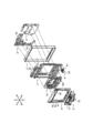
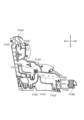
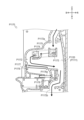
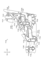
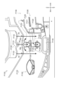
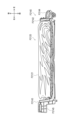
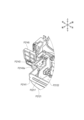
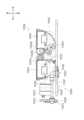
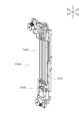
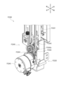
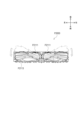
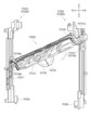
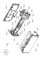
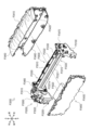
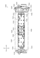
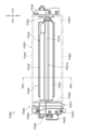
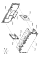
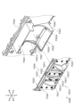
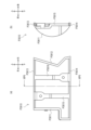
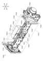
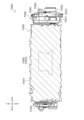
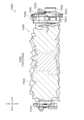
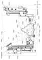
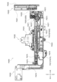
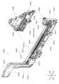
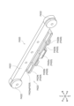
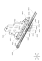
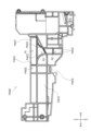
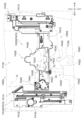
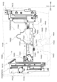
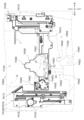
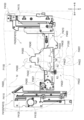
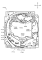
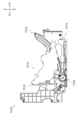
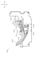
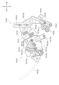
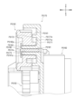
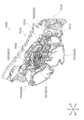
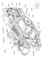
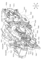
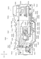
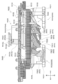
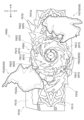
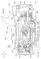
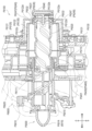
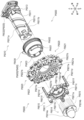
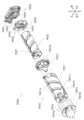
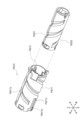
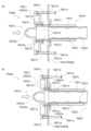
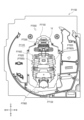
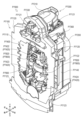
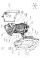
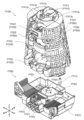
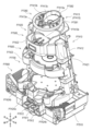
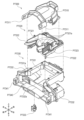
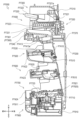
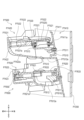
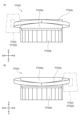
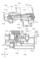
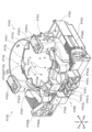
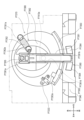
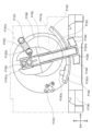
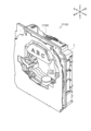
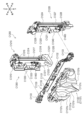
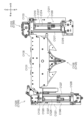
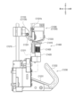
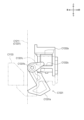
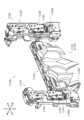
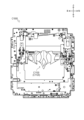
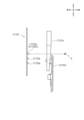
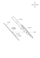
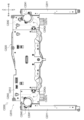
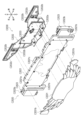
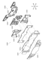
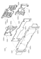
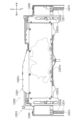
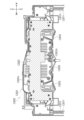
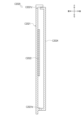
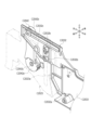
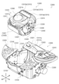
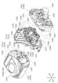
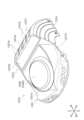
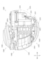
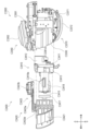
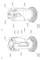
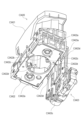
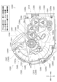
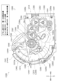
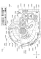
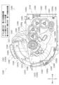
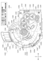
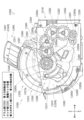
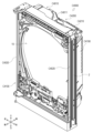
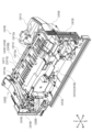
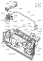
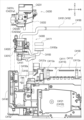
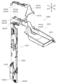
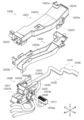
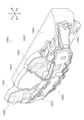
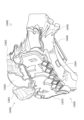
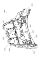
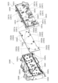
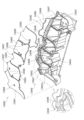
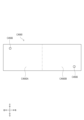
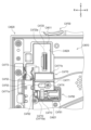
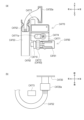
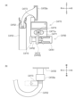
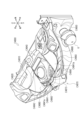
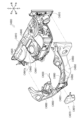
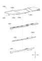
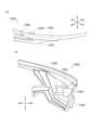
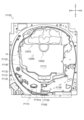
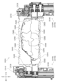
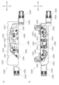
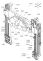
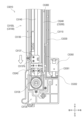
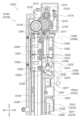
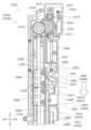
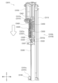
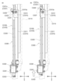
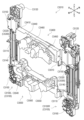
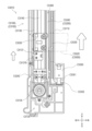
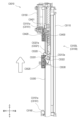
図1は、第1のパチンコ遊技機を前方向右斜め上から見たときの外観を示す斜視図の一
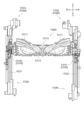
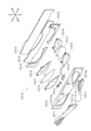
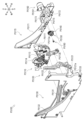
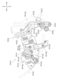
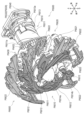
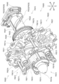
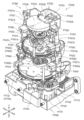
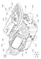
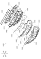
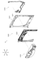
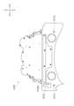
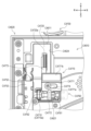
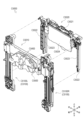
例である。図2は、第1のパチンコ遊技機を前方向右斜め上から見たときの分解斜視図の
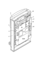
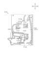
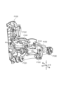
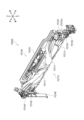
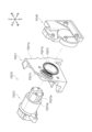
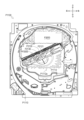
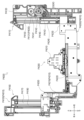
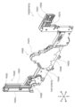
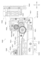
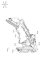
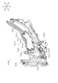
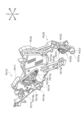
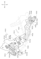
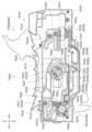
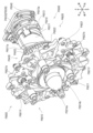
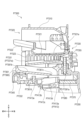
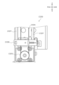
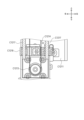
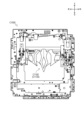
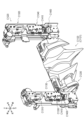
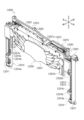
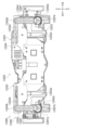
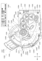
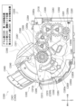
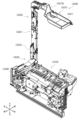
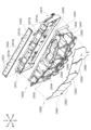
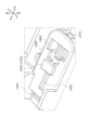
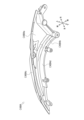
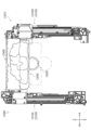
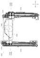
一例である。図3は、第1のパチンコ遊技機を後方向右斜め上から見たときの外観を示す
斜視図の一例である。
[1-1. Appearance]
Fig. 1 is an example of a perspective view showing the appearance of the first pachinko gaming machine when viewed from diagonally above the front right. Fig. 2 is an example of an exploded perspective view of the first pachinko gaming machine when viewed from diagonally above the front right. Fig. 3 is an example of a perspective view showing the appearance of the first pachinko gaming machine when viewed from diagonally above the rear right.
[1-1-1.基本構成]
図1~図3に示されるように、第1のパチンコ遊技機は、外枠2、ベースドア3、ガラ
スドア4、皿ユニット5、発射装置6、表示装置7(図2参照)、払出ユニット8(図2
、図3参照)、基板ユニット9(図2、図3参照)、および、遊技盤ユニット10(図2
参照)等を備える。さらに、遊技盤ユニット10の右下部にはLEDユニット160(図
2参照)が設けられている。ここでは、外枠2、ベースドア3、ガラスドア4、皿ユニッ
ト5、発射装置6、表示装置7、払出ユニット8および基板ユニット9について簡単に説
明し、遊技盤ユニット10およびLEDユニット160についての詳細を後述する。なお
、上記の括弧書きは、図1に図示がない構成についての参照図面を示している。
[1-1-1. Basic configuration]
As shown in FIGS. 1 to 3, the first pachinko gaming machine includes an
3), a board unit 9 (see FIGS. 2 and 3), and a game board unit 10 (see FIG. 2
In addition, an LED unit 160 (see FIG. 2) is provided at the lower right of the
(外枠)
外枠2は、正面視略矩形状の枠体であり、前後方向に貫通する開口21を有する。この
外枠2は、遊技場の島設備に固定して取り付けられる。外枠2の例えば左端部の前側には
蝶番(参照符号なし)が設けられており、この蝶番には、ベースドア3が軸支されている
。このようにすることで、蝶番を軸として外枠2に対してベースドア3を前方に回動させ
ることが可能となっている。
(Outer frame)
The
なお、外枠2は、ベースドア3を介して、後述する払出ユニット8、基板ユニット9、
表示装置7、遊技盤ユニット10、ガラスドア4および皿ユニット5等の多数の部材を支
持するため、高い強度が必要とされる。その一方で、演出効果を高めることを目的として
例えば表示装置7(図2参照)や遊技盤ユニット10の大型化が要求されている。そのた
め、外枠2を例えば薄板の金属で構成することにより、表示装置7や遊技盤ユニット10
の大型化を図りつつ、高い強度を保つことができる。とくに外枠2をアルミ製にすれば、
軽量化を図ることも可能となる。
The
High strength is required to support many components such as the
It is possible to increase the size while maintaining high strength. In particular, if the
It is also possible to reduce weight.
(ベースドア)
ベースドア3は、裏面側に例えば払出ユニット8および基板ユニット9等が取り付けら
れており、これらを支持している。
(Base door)
The
ベースドア3の表面側には遊技盤ユニット10がはめ込まれる。また、ベースドア3の
例えば左端部の前側には、上端部、上下方向略中央部よりも下方側の中途部、および、下
端部のそれぞれに蝶番(参照符号なし)が設けられており、上端部および中途部の蝶番に
ガラスドア4が軸支され、中途部および下端部の蝶番に皿ユニット5がそれぞれ軸支され
ている。このようにすることで、蝶番を軸としてベースドア3に対してガラスドア4およ
び皿ユニット5を一体でまたは個別に前方に回動させることが可能となっている。
A
また、ベースドア3の表面側の例えば右側下方には発射装置6が固定して取り付けられ
ており、例えば上方側の左右のそれぞれには、スピーカ32(図2参照)が固定して取り
付けられている。このスピーカ32からは、例えば、表示装置7に表示されるキャラクタ
等の音声演出、楽曲、効果音、音声による告知、エラー報知等の演出音等が出力される。
The
さらに、ベースドア3の蝶番と反対側(すなわち右端部)には、施錠装置(不図示)が
設けられている。この施錠装置は、外枠2に対してベースドア3を施錠したり、ベースド
ア3に対してガラスドア4を施錠したりする機能を備えている。
Furthermore, a locking device (not shown) is provided on the opposite side (i.e., the right end) of the
(ガラスドア)
ガラスドア4は、開口41が形成された枠状の部材である。この開口41には、透過性
を有する保護ガラス43(図2参照)が後面側から取り付けられている。ガラスドア4が
ベースドア3に対して閉じられると、遊技盤ユニット10に形成される遊技領域105(
後述の図4参照)と保護ガラス43とが対向する。このようにして、ガラスドア4がベー
スドア3に対して閉じられた状態で遊技領域105を前方から視認することができるとと
もに、遊技領域105を流下する遊技球が前方に飛び出さないようにすることができる。
(Glass door)
The
4 described later) faces the
なお、保護ガラス43は、複数枚(例えば2枚)のガラスを互いに間隙を有して取り付
けるものであってもよいし、互いに間隙を有するように複数枚のガラスがユニット化され
たものであってもよい。さらには、ユニット化されたものである場合、ガラスとガラスと
の間に例えば導光板が備えられたものであってもよい。上記の保護ガラス43は、ガラス
製に限られず、例えば透明樹脂製であってもよい。
The
また、ガラスドア4の下部には、遊技情報提供サービス(例えば、「ユニメモ(登録商
標)」)の提供を受けるために例えば遊技者が操作することが可能な操作部66が設けら
れる。この操作部66は、遊技場の管理者等がホールメニュー画面上で操作することが可
能な操作部として機能させることもできる。
In addition, an
また、ガラスドア4の上部には、上述したスピーカ32の前方に配置されるスピーカカ
バー45が設けられている。さらに、ガラスドア4の開口41の周縁部には、発光演出等
に用いられる多数のLED群46が配置されており、これらのLED群46の前方にはL
EDカバーが設けられている。図1および図2において図示される符号46は、厳密にい
えばLEDカバーであるが、便宜上、LED群46として説明する。LED群46は、例
えば、光での告知や、さまざまなバリエーションで発光演出等を行う演出用の発光手段で
あるが、このような発光演出等を実行できればLEDに限られず、例えば液晶やランプ等
であってもよい。
A
1 and 2 is an LED cover, strictly speaking, but for convenience, it will be described as an
(皿ユニット)
皿ユニット5は、上皿51と下皿52とをユニット化したものである。皿ユニット5は
、ベースドア3の前下部であって、ガラスドア4の下方に配置される。この皿ユニット5
は、例えば球詰まり等の発生時に遊技場の店員等が球詰まりを解消できるように、上述し
たとおり、ベースドア3に対して回動させて開閉できるように構成されている。なお、皿
ユニット5は、必ずしも上皿51と下皿52とをそれぞれ設ける必要はなく、一体皿とし
て構成してもよい。
(Dish unit)
The
As described above, the
上皿51は、遊技球を貯留可能に設けられており、上皿51に貯留された遊技球は、発
射装置6から遊技領域105(後述の図4参照)に向けて発射される。上皿51には、払
出口53および演出ボタン54等が設けられる。貸し出される遊技球や賞球として払い出
される遊技球は、払出口53から上皿51に払い出される。演出ボタン54は、所謂「C
HANCEボタン」や、「プッシュボタン」等と呼ばれるものである。演出ボタン54は
、遊技者によって操作される操作機能の他、所定の演出機能を有してもよい。所定の演出
機能としては、例えば特別図柄の当り判定処理の結果に基づいて振動したり上方に突出す
るような機能が相当する。また、上記操作部66の機能を兼用するようにしてもよい。
The
This is called a "HANCE button" or a "push button". The
下皿52は、主として上皿51から溢れた遊技球を貯留するためのものである。下皿5
2には上皿51と連通する払出口55が設けられており、上皿51から溢れた遊技球は払
出口55から下皿52に払い出される。
The
2 is provided with a
下皿52の底面には、遊技者の操作によって開閉させることが可能な開口部(参照符号
なし)が形成されている。下皿52の底面に形成された開口部を開状態にすると、下皿5
2に貯留されている遊技球を、下皿52の下方に載置された球箱に移すことができる。な
お、所謂各台計数システムが各台に設けられている場合、球箱を必要としないだけでなく
、各台計数システムで計数された遊技球を貯球し、貯球された遊技球を再び遊技に供する
こともできる。
An opening (without a reference symbol) that can be opened and closed by the player is formed on the bottom surface of the
The game balls stored in the
(発射装置)
発射装置6は、上皿51に貯留された遊技球を、遊技領域105(後述の図4参照)に
向けて発射するためのものである。発射装置6は、ベースドア3の前右下部であって、皿
ユニット5の右下方に配置される。発射装置6は、パネル体61、駆動装置(不図示)お
よび発射ハンドル62を備える。
(Launch device)
The
パネル体61は、ベースドア3に対し皿ユニット5が閉じられた状態において、皿ユニ
ット5と、ベースドア3に固定して取り付けられた発射装置6とが外観上一体となるよう
に設けられる。
The
発射ハンドル62は、右回りまたは左回りに回動可能に構成されており、パネル体61
の表面側に配置される。上記の駆動装置は、パネル体61の裏面側に配置され、例えば発
射ソレノイド(図示せず)により構成される。遊技者によって発射ハンドル62が操作さ
れると、駆動装置の動作により遊技球が発射される。なお、発射ハンドル62を操作する
際に、右回りへの回動量(操作量)が大きいほど遊技球の発射強度が強くなる。
The firing handle 62 is configured to be rotatable clockwise or counterclockwise.
The drive device is disposed on the front side of the
皿ユニット5の右下方に配置された発射装置6から発射された遊技球は、発射レール(
不図示)を経てガイドレール110(後述の図4参照)に沿って円弧状に転動して遊技領
域105(後述の図4参照)に打ち出される。なお、発射装置6の配置位置は、皿ユニッ
ト5の右下方に限られず、皿ユニット5の左下方であってもよい。この場合、上記の発射
レールが不要となり、ガラスドア4の下方の領域を有効に利用することができ、汎用性を
高めることが可能となる。
The game balls launched from the
The balls pass through a guide rail 110 (not shown) and roll in an arc along the guide rail 110 (see FIG. 4 described later) to be launched into the play area 105 (see FIG. 4 described later). The location of the
(表示装置)
表示装置7(図2参照)は、遊技に関する各種の演出画像を表示する表示領域を有する
ものであって、遊技パネル100の開口に上記の表示領域が臨むように取り付けられる。
表示装置7は、例えば、液晶表示装置、7セグ表示装置、ドットマトリクス表示装置、エ
レクトロルミネッセンスで構成される表示装置等であってもよいし、プロジェクタ等の投
影装置を用いて映像を投影するものであってもよい。表示装置7の表示領域には、例えば
、演出用識別図柄(例えば、装飾図柄)を可変表示させて特別図柄の当り判定処理の結果
を表示したり、特別図柄の当り判定処理の結果に応じた演出画像、大当り遊技状態中の演
出画像、デモ演出画像、特別図柄の可変表示の保留状況を示す演出画像等が表示される。
本実施例では、表示装置7が遊技盤ユニット10に取り付けられているが、表示装置7の
表示領域が遊技パネル100の開口に臨むように配置されていれば、表示装置7はベース
ドア3に取り付けられるようにしてもよい。
(Display Device)
The display device 7 (see FIG. 2) has a display area for displaying various presentation images relating to the game, and is attached to the opening of the
The
In this embodiment, the
なお、本実施例では、上記各種の演出画像を表示するものとして一つの表示装置7を備
えているが、複数(例えば二つ)の表示装置を設けて、これら複数の表示装置を用いて演
出画像を表示するようにしても良い。
In this embodiment, one
(払出ユニット)
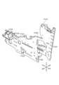
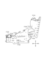
払出ユニット8(図2、図3参照)は、ベースドア3の背面側に配置されており、球通
路81、払出装置82等で構成される。球通路81には、貯留タンク80(図2、図3参
照)から遊技球が供給される。なお、貯留タンク80には、島設備(不図示)から遊技球
が供給される。払出装置82は、払出条件が成立すると、貯留タンク80から球通路81
に供給された遊技球のうち所定個数の遊技球を例えば上皿51に払い出す。また、払出ユ
ニット8の背面側には、図3に示されるように電源スイッチ95が設けられる。
(Payout unit)
The payout unit 8 (see Figures 2 and 3) is disposed on the rear side of the
Of the game balls supplied to the
(基板ユニット)
基板ユニット9(図2、図3参照)は、ベースドア3の背面側に配置される。基板ユニ
ット9には、各種制御基板等が設けられる。
(Board unit)
The board unit 9 (see Figs. 2 and 3) is disposed on the rear side of the
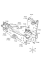
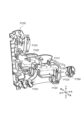
具体的には、図3に示されるように、主制御回路200(後述の図6参照)が実装され
た主制御基板91、サブ制御回路300(後述の図6参照)が実装されたサブ制御基板9
2、遊技球の払出・発射を制御する払出・発射制御回路400(後述の図6参照)が実装
された払出・発射制御基板93、および、電源を供給する電源供給回路450(後述の図
6参照)が実装された電源供給基板等が基板ユニット9に設けられている。
Specifically, as shown in FIG. 3, a
2. The
なお、図3では、便宜上、主制御基板91、サブ制御基板92、払出・発射制御基板9
3および電源供給基板94を参照符号として示しているが、これらの基板は、全て、基板
ケースに収容されている。
In FIG. 3, for convenience, a
3 and a
また、本実施例では、サブ制御基板92を、ワンボード基板(1つの基板に1つの制御
LSIまたは複数のLSIが設けられた基板)として構成する。ただし、これに限られず
、例えば、後述する表示制御回路304、音声制御回路305、LED制御回路306お
よび役物制御回路307(いずれも後述の図6参照)等の全部または一部を別個の基板と
することで、サブ制御基板92を複数の基板で構成してもよい。
In this embodiment, the
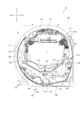
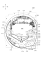
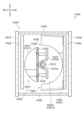
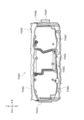
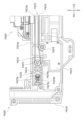
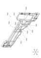
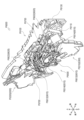
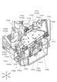
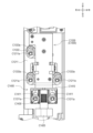
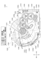
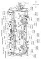
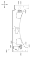
[1-1-2.遊技盤ユニット]
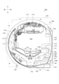
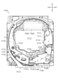
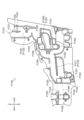
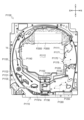
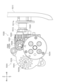
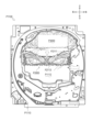
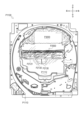
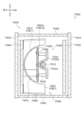
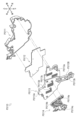
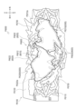
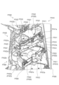
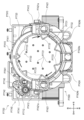
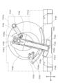
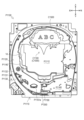
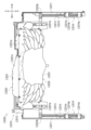
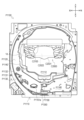
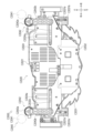
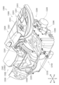
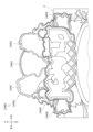
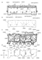
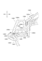
図4は、第1のパチンコ遊技機が備える遊技盤ユニット10の外観を示す正面図の一例
である。遊技盤ユニット10の前側面には、発射された遊技球が転動流下可能な遊技領域
105が形成される。
[1-1-2. Game board unit]
4 is an example of a front view showing the appearance of the
図4に示されるように、遊技盤ユニット10は、主として、発射された遊技球が転動流
下可能な遊技領域105が形成される遊技パネル100と、ガイドレール110と、遊技
領域105の略中央部に配置されるセンター役物115と、第1始動口120と、一般入
賞口122と、通過ゲートユニット125と、特別電動役物ユニット130と、第2始動
口140と、普通電動役物ユニット145と、LEDユニット160と、アウト口178
と、遊技盤ユニット10の後方に配置される裏ユニット(図示せず)とを備える。なお、
上述したとおり、LEDユニット160については後述する。
As shown in FIG. 4, the
and a back unit (not shown) disposed behind the
As mentioned above, the
(遊技パネル)
遊技パネル100には、表示装置7の表示領域が臨む位置に開口(参照符号なし)が形
成されている。また、遊技パネル100の前面には、ガイドレール110が設けられると
ともに遊技釘(参照符号なし)等が植設されている。発射装置6(図1、図2参照)から
発射された遊技球は、ガイドレール110から遊技領域105に向けて飛び出し、遊技釘
等と衝突して進行方向を変えながら遊技領域105の下方に向けて流下する。
(Game panel)
An opening (no reference number) is formed in the
また、遊技パネル100の後方には、演出効果を高めるために装飾体が設けられた裏ユ
ニット(図示せず)が配置されている。遊技パネル100は、裏ユニットに設けられた装
飾体を正面視で視認できるように透明樹脂で構成されている。この場合、遊技パネル10
0の全部が透明部材で構成されていてもよいし、例えば、裏ユニットに設けられた装飾体
を正面視で視認できる部位のみが透明部材で構成されていてもよい。また、遊技パネル1
00を、透明部分を有さない部材(例えば木製)で構成し、一部に透明部材を設けて演出
効果を高めるようにしてもよい。
In addition, a back unit (not shown) on which a decorative body is provided to enhance the presentation effect is disposed behind the
The entirety of the
00 may be constructed from materials that do not have transparent parts (e.g., wood), with transparent materials provided in some areas to enhance the presentation effect.
なお、本実施例では、裏ユニットを正面視で視認できるように遊技パネル100が透明
樹脂で構成されているが、遊技パネル100の全部を透明としてもよいし、一部のみを透
明としてもよい。
In this embodiment, the
(ガイドレール)
ガイドレール110は、円弧状の外レールおよび内レール(いずれも参照符号なし)に
より構成される。遊技領域105は、ガイドレール110によって区画(画定)される。
外レールおよび内レールは、発射装置6(後述の図6参照)から発射された遊技球を遊技
領域105の上部に案内する機能を有する。
(Guide rail)
The
The outer rail and the inner rail have the function of guiding the game balls launched from the launching device 6 (see Figure 6 described below) to the upper part of the
(センター役物)
センター役物115は、遊技パネル100の開口(参照符号なし)にはめ込まれるよう
に構成されており、上方には円弧状のセンターレール116を備えている。遊技領域10
5に向けて発射された遊技球は、センターレール116によって左右に振り分けられる。
(Center role)
The
The game ball shot toward 5 is distributed to the left and right by the
この第1のパチンコ遊技機において、遊技領域105のうち、センター役物115より
も左側の領域を左側領域106と称し、センター役物115よりも右側の領域を右側領域
107と称する。左側領域および右側領域の定義は、後述する第2のパチンコ遊技機およ
び第3のパチンコ遊技機についても同様である。
In this first pachinko game machine, the area of the
発射装置6によって遊技領域105に向けて発射された遊技球は、左側領域106また
は右側領域107を流下する。左側領域106または右側領域107を流下する遊技球は
、遊技パネル100に植設された遊技釘等との衝突により、進行方向を変えながら下方へ
向けて流下する。発射ハンドル62(図1、図2参照)の操作量が小さい場合、発射され
た遊技球は左側領域106を流下する。一方、発射ハンドル62(図1参照)の操作量が
大きい場合、発射された遊技球は右側領域107を流下する。
A game ball launched by the
なお、この明細書において、発射ハンドル62の操作態様(打ち方)として、左側領域
106を流下するように遊技球を発射させる打ち方を「左打ち」と称し、右側領域107
を流下するように遊技球を発射させる打ち方を「右打ち」と称する。このように、遊技者
によって左側領域106または右側領域107に向けて遊技球を打ち分け可能とされてい
る。
In this specification, as an operation mode (hitting method) of the
The hitting style in which the game ball is shot so as to flow down the
また、センター役物115には、左側の外周縁部に、左側領域106を流下する遊技球
が進入可能とされたワープ入口117が形成されている。ワープ入口117に進入した遊
技球は、センター役物115に形成されたステージ118に誘導可能に構成されている。
ステージ118は、表示装置7の表示領域の下辺前方において遊技球が左右方向に転動可
能に形成されている。なお、ステージ118は、例えば、上段側のステージおよび下段側
のステージといったように、複数段で形成されていてもよい。
In addition, a
The
ステージ118の左右方向略中央の後側には、遊技球が進入可能なチャンス入口119
が形成されており、チャンス入口119に進入した遊技球は、第1始動口120の直上に
放出されるように構成されている。そのため、チャンス入口119に進入した遊技球は、
ワープ入口117に進入しなかった遊技球や、ワープ入口117に進入したもののチャン
ス入口119に進入しなかった遊技球と比べて高い確率で第1始動口120に入賞(通過
)するようになっている。
At the rear of the
is formed, and the game ball that enters the
The probability of the game ball entering (passing) the
(第1始動口)
第1始動口120は、表示装置7の表示領域の下方に配置されており、左打ちされた遊
技球が入賞可能(右打ちされた遊技球が入賞困難または不可能)となるように配置されて
いる。第1始動口120に遊技球が入賞すると、第1始動口スイッチ121(後述の図6
参照)により検出される。なお、右打ちされた遊技球が第1始動口120に入賞可能であ
ってもよい。また、上記の第1始動口120に代えてまたは加えて、右打ちされた遊技球
が入賞可能(左打ちされた遊技球が入賞困難または不可能)な第1始動口を備えるように
してもよい。
(First starting point)
The
Refer to FIG. 13.) It should be noted that a game ball hit from the right may be able to win in the
第1始動口スイッチ121(後述の図6参照)により第1始動口120への遊技球の入
賞(通過)が検出されると、第1特別図柄にかかる各種データ(例えば、第1特別図柄の
大当り判定用乱数値、第1特別図柄の図柄乱数値、第1特別図柄のリーチ判定用乱数値、
および、第1特別図柄の演出選択用乱数値等の各種乱数値等)が抽出され、抽出された各
種データは所定数(例えば最大4個)まで記憶される。記憶された各種データは、第1特
別図柄の始動条件(この明細書において「第1特別図柄の変動開始条件」とも称する)が
成立すると、第1特別図柄の当り判定処理に供される。第1始動口120に遊技球が入賞
すると例えば3個の賞球が払い出される。ただし、第1始動口120への遊技球の入賞に
基づいて払い出される賞球数はこれに限られない。
When the first start hole switch 121 (see FIG. 6 described later) detects the entry (passage) of a game ball into the
and various random numbers such as a random number for selecting the effect of the first special symbol) are extracted, and the various extracted data are stored up to a predetermined number (for example, up to four). When the start condition of the first special symbol (also referred to in this specification as the "variation start condition of the first special symbol") is established, the various stored data are used in the winning determination process of the first special symbol. When a gaming ball enters the
この明細書において、第1始動口120への遊技球の入賞を第1特別図柄の始動入賞と
称し、第1特別図柄にかかる各種データ(例えば、第1特別図柄の大当り判定用乱数値、
第1特別図柄の図柄乱数値、第1特別図柄のリーチ判定用乱数値、および、第1特別図柄
の演出選択用乱数値等の各種乱数値等)を第1特別図柄の始動情報と称する。また、始動
条件が成立するまで第1特別図柄の始動情報を記憶することを保留と称する。第2特別図
柄についても同様である。
In this specification, the entry of a gaming ball into the
The random number value of the first special symbol, the random number value for reach judgment of the first special symbol, and the random number value for performance selection of the first special symbol, etc. are called the start information of the first special symbol. In addition, storing the start information of the first special symbol until the start condition is established is called reservation. The same applies to the second special symbol.
(一般入賞口)
一般入賞口122は、表示装置7の表示領域の左下方に複数配置されており、左打ちさ
れた遊技球が入賞可能(右打ちされた遊技球が入賞困難または不可能)となるように配置
されている。複数の一般入賞口122のうちいずれかに遊技球が入賞すると、一般入賞口
スイッチ123(後述の図6参照)により検出される。
(General prize entry)
A plurality of general winning
一般入賞口スイッチ123(後述の図6参照)により一般入賞口122への遊技球の入
賞(通過)が検出されると、例えば4個の賞球が払い出されるが、一般入賞口122への
遊技球の入賞に基づいて払い出される賞球数は4個に限られない。
When the general prize opening switch 123 (see Figure 6 described below) detects the entry (passage) of a game ball into the
また、本実施例において、一般入賞口122は、右打ちされた遊技球が入賞困難または
不可能となるように配置されているが、必ずしもこれに限られず、上記の一般入賞口12
2に代えてまたは加えて、右打ちされた遊技球が入賞可能な一般入賞口を備えてもよい。
In this embodiment, the general winning
In place of or in addition to 2, a general winning hole may be provided through which a game ball hit to the right can win a prize.
(通過ゲートユニット)
通過ゲートユニット125は、右側領域107に配置されており、右打ちされた遊技球
がほぼ通過できるように構成された通過ゲート126と、通過ゲート126への遊技球の
通過を検出する通過ゲートスイッチ127(後述の図6参照)とを一体化したユニット体
である。
(Passing gate unit)
The
通過ゲートスイッチ127により通過ゲート126への遊技球の通過が検出されると、
普通図柄にかかる各種データ(例えば、普通図柄の当り判定用乱数値等)が抽出され、抽
出された各種データは所定数(例えば最大4個)まで記憶される。記憶された各種データ
は、普通図柄の当り判定処理に供される。なお、通過ゲートスイッチ127により通過ゲ
ート126への遊技球の通過が検出されたとしても、賞球は払い出されない。また、通過
ゲートユニット125は、右側領域107に代えてまたは加えて左側領域106に配置さ
れていてもよい。
When the passing
Various data related to the normal symbols (e.g., random numbers for determining whether the normal symbols are winning, etc.) are extracted, and the extracted various data are stored up to a predetermined number (e.g., up to four). The stored various data are used for the process of determining whether the normal symbols are winning. Note that even if the passing
この明細書において、通過ゲート126への遊技球の通過を始動通過と称し、通過ゲー
ト126への遊技球の通過によって抽出された普通図柄にかかる各種データ(例えば、普
通図柄の当り判定用乱数値等)を普通図柄の始動情報と称する。また、始動条件が成立す
るまで普通図柄の始動情報を記憶することを保留と称する。
In this specification, the passage of the game ball through the
(特別電動役物ユニット)
特別電動役物ユニット130は、大入賞口131と、大入賞口131への遊技球の入賞
(通過)を検出するカウントスイッチ132(後述の図6参照)と、特別電動役物133
とを一体化したユニット体である。特別電動役物ユニット130は、右側領域107にお
いて、通過ゲートユニット125よりも下方に配置されている。
(Special electric feature unit)
The special
The special
大入賞口131は、右打ちされた遊技球が入賞可能(左打ちされた遊技球が入賞困難ま
たは不可能)となるように配置されている。ただし、これに限定されるものではなく、上
記の大入賞口131に代えてまたは加えて、左打ちされた遊技球が入賞可能な大入賞口を
配置したり、センター役物115の上部において遊技球が入賞可能な大入賞口を配置する
ようにしてもよい。
The
また、大入賞口131は、遊技者に有利な遊技状態である大当り遊技状態に制御されて
いるときに所定個数(例えば10個)の遊技球が入賞(通過)可能となるように開放され
る入賞口である。カウントスイッチ132(後述の図6参照)により大入賞口131への
遊技球の入賞が検出されると、例えば10個の賞球が払い出される。ただし、大入賞口1
31への遊技球の入賞に基づいて払い出される賞球数は10個に限られない。
The
The number of winning balls paid out based on the winning of a gaming ball on 31 is not limited to 10.
特別電動役物133は、前後方向に進退可能な特電用シャッタ134と、この特電用シ
ャッタ134を作動させる特電用ソレノイド135(後述の図6参照)とを備える。特別
電動役物133すなわち特電用シャッタ134は、大入賞口131への遊技球の入賞(通
過)が可能または容易な開放状態と、大入賞口131への遊技球の入賞(通過)が不可能
または困難な閉鎖状態と、に状態移行可能に構成される。なお、大当り遊技状態では、上
記の閉鎖状態から開放状態への状態移行が所定のラウンド数にわたって行われる。すなわ
ち、大当り遊技状態は、大入賞口131が閉鎖状態から所定期間にわたって開放状態に移
行するラウンド遊技を複数ラウンドにわたって行うことにより、多量の遊技球を賞球とし
て払い出すことを可能にした遊技状態である。
The special
(第2始動口)
第2始動口140は、左側領域106(より詳しくは第1始動口120の左側下方)に
配置されている。ただし、第2始動口140は、左打ちされた遊技球の入賞が例えば遊技
釘等によって困難または不可能となっており、右打された遊技球が入賞可能となるように
第2始動口140の近傍まで誘導されるように構成されている。ただし、第2始動口14
0をこのような構成とすることは必須ではなく、例えば右側領域107に設けてもよい。
また、第2始動口140は、左打ちされた遊技球が入賞可能となるように構成されていて
もよい。
(Second starting hole)
The
It is not essential that the
In addition, the
第2始動口スイッチ141(後述の図6参照)により第2始動口140への遊技球の入
賞(通過)が検出されると、第2特別図柄にかかる各種データ(例えば、第2特別図柄の
大当り判定用乱数値、第2特別図柄の図柄乱数値、第2特別図柄のリーチ判定用乱数値、
および、第2特別図柄の演出選択用乱数値等の各種乱数値等)が抽出され、抽出された各
種データは所定数(例えば最大4個)まで記憶される。記憶された各種データは、第2特
別図柄の始動条件(この明細書において「第2特別図柄の変動開始条件」とも称する)が
成立すると、第2特別図柄の当り判定処理に供される。第2始動口140に遊技球が入賞
すると例えば3個の賞球が払い出される。ただし、第2始動口140への遊技球の入賞に
基づいて払い出される賞球数はこれに限られない。
When the entry (passage) of the game ball into the
and various random numbers such as a random number for selecting the effect of the second special symbol) are extracted, and the extracted various data are stored up to a predetermined number (for example, up to four). When the start condition of the second special symbol (also referred to in this specification as the "variation start condition of the second special symbol") is established, the stored various data is used for the winning determination process of the second special symbol. When a gaming ball enters the
(普通電動役物ユニット)
普通電動役物ユニット145は、左側領域106(より詳しくは第1始動口120の左
側下方)に配置されており、遊技球が入賞(通過)することによって所定数の遊技球が賞
球として払い出される入賞口と、この入賞口への遊技球の入賞を検出するスイッチと、普
通電動役物146とを一体化したユニット体である。本実施例では、上記の入賞口を第2
始動口140とし、上記のスイッチを第2始動口スイッチ141としている。
(Normal electric role unit)
The normal
This is called a
普通電動役物146は、所謂電チューと呼ばれる例えば羽根部材からなる普電用可動部
材147と、この普電用可動部材147を作動させる普電用ソレノイド148(後述の図
6参照)とを備える。普通電動役物146すなわち普電用可動部材147は、第2始動口
140への遊技球の入賞(通過)が可能または容易な開放状態と、第2始動口140への
遊技球の入賞が不可能または困難な閉鎖状態と、に状態移行可能に構成される。なお、普
電用可動部材147は、羽根型、扉型、突出板型等を含む。
The normal
(アウト口)
アウト口178は、遊技領域105に向けて発射されたものの各種入賞口(例えば、第
1始動口120、第2始動口140、大入賞口131、一般入賞口122等)のいずれに
も入賞しなかった遊技球を、機外に排出するためのものである。このアウト口178は、
左打ちされた遊技球および右打ちされた遊技球のいずれについても機外に排出できるよう
に、遊技領域105の最下流側に設けられている。ただし、上記のアウト口178に加え
て、最下流側でない位置、例えば複数の一般入賞口122の間等にアウト口を設けて、遊
技領域105を流下中の遊技球を機外に排出するようにしてもよい。
(Outlet)
The outlet 178 is for discharging game balls that have been shot toward the
It is provided on the most downstream side of the
(裏ユニット)
裏ユニット(不図示)は、遊技盤ユニット10を装飾するものであって、透過性のある
遊技パネル100の後方側に設けられる。この裏ユニットは、サブ制御回路300によっ
て制御される可動役物等の演出用役物群58(後述の図6参照)を備える。演出用役物群
58は、例えば表示装置7の表示領域の周囲に配置される。これらの演出用役物群58の
うち少なくとも一以上の役物または役物を構成する演出用役物構成部材は、特別図柄の当
り判定処理の結果にもとづいて動作可能な演出用役物として機能する。
(Back unit)
The back unit (not shown) is for decorating the
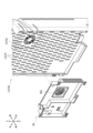
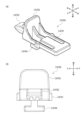
[1-1-3.LEDユニット]
LEDユニット160は、遊技盤ユニット10の右下部であって、遊技領域105の外
側に配置される(例えば図4参照)。LEDユニット160は、各種の表示部を一体化し
たユニット体である。
[1-1-3. LED unit]
The
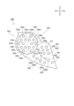
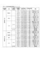
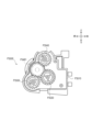
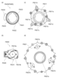
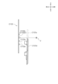
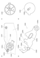
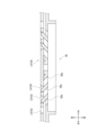
図5は、第1のパチンコ遊技機が備えるLEDユニット160を示す正面図の一例であ
る。
FIG. 5 is an example of a front view showing the
図5に示されるように、LEDユニット160は、普通図柄表示部161、普通図柄用
保留表示部162、第1特別図柄表示部163、第2特別図柄表示部164、第1特別図
柄用保留表示部165、第2特別図柄用保留表示部166、確変報知用表示部167、お
よび時短報知用表示部168を備える。
As shown in Figure 5, the
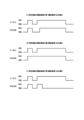
(普通図柄表示部)
普通図柄表示部161は、普通図柄の当り判定処理の結果を表示するものであって、普
通図柄表示LED161a,161bを備える。普通図柄の可変表示を開始するための条
件(以下、「普通図柄の始動条件」と称する)が成立すると、普通図柄表示LED161
a,161bが交互に点灯・消灯を繰り返す普通図柄の可変表示が開始される。普通図柄
の可変表示が開始されてから所定時間が経過すると、普通図柄の可変表示が停止し、普通
図柄の当り判定処理の結果が導出される。
(Normal pattern display section)
The normal
The variable display of the normal symbol is started, in which the normal symbols 161a, 161b are alternately turned on and off. When a predetermined time has elapsed since the variable display of the normal symbol was started, the variable display of the normal symbol is stopped, and the result of the winning determination process of the normal symbol is derived.
普通図柄の当り判定処理の結果が普通図柄当りである場合、普通図柄表示LED161
a,161bの点灯・消灯の組み合わせが特定の停止表示態様となる。例えば、普通図柄
の当り判定処理の結果が普通図柄当りである場合、普通図柄表示LED161aが点灯す
るとともに普通図柄表示LED161bが消灯する。一方、普通図柄の当り判定処理の結
果がハズレである場合、例えば、普通図柄表示LED161aが消灯するとともに普通図
柄表示LED161bが点灯する。ただし、普通図柄の当り判定処理の結果を示す普通図
柄表示LED161a,161bの停止表示態様はこれに限られない。そして、普通図柄
が特定の停止表示態様で停止表示されると、普通電動役物146を作動させることが決定
し、普電用可動部材147が所定のパターンで開閉駆動し、第2始動口140への遊技球
の入賞(通過)が容易となる。
When the result of the normal symbol winning judgment process is a normal symbol winning, the normal
A combination of the on/off of the LEDs 161a and 161b is a specific stop display mode. For example, if the result of the normal symbol hit determination process is a normal symbol hit, the normal symbol display LED 161a is turned on and the normal symbol display LED 161b is turned off. On the other hand, if the result of the normal symbol hit determination process is a miss, for example, the normal symbol display LED 161a is turned off and the normal symbol display LED 161b is turned on. However, the stop display mode of the normal symbol display LEDs 161a and 161b indicating the result of the normal symbol hit determination process is not limited to this. Then, when the normal symbol is stopped and displayed in a specific stop display mode, it is determined that the normal
(普通図柄用保留表示部)
普通図柄用保留表示部162は、普通図柄の始動情報すなわち可変表示が保留されてい
る場合、保留されている普通図柄の可変表示の数(以下、「普通図柄の保留数」と称する
)を表示するものであって、普通図柄用保留表示LED162a,162bを備える。上
記の「普通図柄の可変表示が保留されている」とは、通過ゲート126への遊技球の通過
が検出されて普通図柄にかかる各種データ(例えば、普通図柄の当り判定用乱数値等)が
抽出されてから、普通図柄の始動条件が成立するまでの状態をいう。なお、普通図柄の始
動条件は、普通図柄が可変表示中でないこと、および、普通図柄の可変表示が保留されて
いること、を少なくとも全て満たす場合に成立する。
(Regular pattern reserved display section)
The
普通図柄用保留表示部162は、普通図柄用保留表示LED162a,162bの点灯
・消灯の組み合わせによって普通図柄の可変表示の保留数を表示する。例えば、普通図柄
の保留数が1個である場合、普通図柄用保留表示LED162aが点灯するとともに普通
図柄用保留表示LED162bが消灯する。また、普通図柄の保留数が2個である場合、
普通図柄用保留表示LED162a,162bの両方が点灯する。また、普通図柄の保留
数が3個である場合、普通図柄用保留表示LED162aが点滅するとともに普通図柄用
保留表示LED162bが点灯する。さらに、普通図柄の保留数が4個である場合、普通
図柄用保留表示LED162a,162bの両方が点滅する。ただし、普通図柄の保留数
を示す普通図柄用保留表示LED162a,162bの表示態様はこれに限られない。
The ordinary symbol reserved
Both of the
(特別図柄表示部)
特別図柄表示部は、特別図柄の当り判定処理の結果を表示するものであって、第1特別
図柄表示部163および第2特別図柄表示部164を備える。第1特別図柄表示部163
は、例えば、8個のLED163a~163hからなる第1特別図柄表示LED群を備え
る。同様に、第2特別図柄表示部164も、例えば8個のLED164a~164hから
なる第2特別図柄表示LED群を備える。
(Special design display section)
The special symbol display unit displays the result of the special symbol winning determination process, and includes a first special
The second special
第1特別図柄の可変表示を開始するための条件(以下、「第1特別図柄の始動条件」と
称する)が成立すると、第1特別図柄表示部163を構成する8個のLED163a~1
63hの全部または一部が交互または相互に点灯・消灯を繰り返す第1特別図柄の可変表
示が開始される。第1特別図柄の可変表示が開始されてから所定時間が経過すると、第1
特別図柄の可変表示が停止し、第1特別図柄の当り判定処理の結果が導出される。
When the condition for starting the variable display of the first special symbol (hereinafter referred to as the "start condition of the first special symbol") is satisfied, the eight
The variable display of the first special symbol, in which all or part of 63h alternately or mutually turns on and off, is started. When a predetermined time has elapsed since the variable display of the first special symbol started,
The variable display of the special symbol stops, and the result of the winning determination process for the first special symbol is derived.
第1特別図柄の当り判定処理の結果が大当りである場合、第1特別図柄表示部163を
構成する8個のLED163a~163hの点灯・消灯の組み合わせが特定の停止表示態
様となる。そして、第1特別図柄表示部163が特定の停止表示態様で停止表示されると
、大当り遊技状態への移行が決定する。
When the result of the hit determination process of the first special symbol is a jackpot, a combination of on/off of the eight
第2特別図柄の可変表示を開始するための条件(以下、「第2特別図柄の始動条件」と
称する)が成立すると、第2特別図柄表示部164を構成する8個のLED164a~1
64hの全部または一部が交互または相互に点灯・消灯を繰り返す第2特別図柄の可変表
示が開始される。第2特別図柄の可変表示が開始されてから所定時間が経過すると、第2
特別図柄の可変表示が停止し、第2特別図柄の当り判定処理の結果が導出される。
When the condition for starting the variable display of the second special symbol (hereinafter referred to as the "start condition of the second special symbol") is satisfied, the eight
The variable display of the second special symbol, in which all or part of 64h alternately or mutually lights up and goes out, is started. When a predetermined time has elapsed since the variable display of the second special symbol started,
The variable display of the special symbol stops, and the result of the winning determination process for the second special symbol is derived.
第2特別図柄の当り判定処理の結果が大当りである場合、第2特別図柄表示部164を
構成する8個のLED164a~164hの点灯・消灯の組み合わせが特定の停止表示態
様となる。そして、第2特別図柄表示部164が特定の停止表示態様で停止表示されると
、大当り遊技状態への移行が決定する。
When the result of the hit determination process of the second special symbol is a jackpot, a combination of on/off of the eight
(特別図柄用保留表示部)
特別図柄用保留表示部は、特別図柄の始動情報すなわち可変表示が保留されている場合
、保留されている特別図柄の可変表示の数(以下、「特別図柄の保留数」と称する)を表
示するものであって、第1特別図柄用保留表示部165および第2特別図柄用保留表示部
166を備える。
(Special design reserved display section)
The special pattern reserve display unit displays the number of reserved special pattern variable displays (hereinafter referred to as the "reserved number of special patterns") when start information for a special pattern, i.e., a variable display, is reserved, and is provided with a first special pattern
第1特別図柄用保留表示部165は、第1特別図柄の可変表示が保留されている場合、
第1特別図柄の保留数を表示するものであって、第1特別図柄用保留表示LED165a
,165bを備える。「第1特別図柄の可変表示が保留されている」とは、第1始動口1
20への遊技球の入賞(通過)が検出されて第1特別図柄の始動情報が抽出されてから、
第1特別図柄の始動条件が成立するまでの状態をいう。
When the variable display of the first special symbol is reserved, the first special symbol reserved
The number of reserved first special symbols is displayed. The
, 165b. "The variable display of the first special symbol is reserved" means that the
After the entry (passage) of the game ball into
This refers to the state until the starting conditions for the first special pattern are met.
第1特別図柄用保留表示部165は、第1特別図柄用保留表示LED165a,165
bの点灯・消灯の組み合わせによって第1特別図柄の可変表示の保留数を表示する。例え
ば、第1特別図柄の保留数が1個である場合、第1特別図柄用保留表示LED165aが
点灯するとともに第1特別図柄用保留表示LED165bが消灯する。また、第1特別図
柄の保留数が2個である場合、第1特別図柄用保留表示LED165a,165bの両方
が点灯する。また、第1特別図柄の保留数が3個である場合、第1特別図柄用保留表示L
ED165aが点滅するとともに第1特別図柄用保留表示LED165bが点灯する。さ
らに、第1特別図柄の保留数が4個である場合、第1特別図柄用保留表示LED165a
,165bの両方が点滅する。ただし、第1特別図柄の保留数を示す第1特別図柄用保留
表示LED165a,165bの表示態様はこれに限られない。
The first special symbol reserved
The number of reserved first special symbols is displayed by a combination of the lighting and extinguishing of the first special symbol reserved
The
However, the display mode of the first special symbol reserved
第2特別図柄用保留表示部166は、第2特別図柄の可変表示が保留されている場合、
第2特別図柄の保留数を表示するものであって、第2特別図柄用保留表示LED166a
,166bを備える。「第2特別図柄の可変表示が保留されている」とは、第2始動口1
40への遊技球の入賞(通過)が検出されて第2特別図柄の始動情報が抽出されてから、
第2特別図柄の始動条件が成立するまでの状態をいう。
The second special symbol reserved
The number of reserved second special symbols is displayed. The
, 166b. "The variable display of the second special symbol is reserved" means that the
After the entry (passage) of the game ball into 40 is detected and the start information of the second special symbol is extracted,
This refers to the state until the starting conditions for the second special pattern are met.
第2特別図柄用保留表示部166は、第2特別図柄用保留表示LED166a,166
bの点灯・消灯の組み合わせによって第2特別図柄の可変表示の保留数を表示する。例え
ば、第2特別図柄の保留数が1個である場合、第2特別図柄用保留表示LED166aが
点灯するとともに第2特別図柄用保留表示LED166bが消灯する。また、第2特別図
柄の保留数が2個である場合、第2特別図柄用保留表示LED166a,166bの両方
が点灯する。また、第2特別図柄の保留数が3個である場合、第2特別図柄用保留表示L
ED166aが点滅するとともに第2特別図柄用保留表示LED166bが点灯する。さ
らに、第2特別図柄の保留数が4個である場合、第2特別図柄用保留表示LED166a
,166bの両方が点滅する。ただし、第2特別図柄の保留数を示す第2特別図柄用保留
表示LED166a,166bの表示態様はこれに限られない。
The second special symbol reserved
The number of reserved second special symbols is displayed by a combination of lighting and extinguishing
The
However, the display mode of the second special symbol reserved
(確変報知用表示部)
確変報知用表示部167は、後述の確変制御の実行中に点灯させることが可能であって
、例えばLEDまたはランプで構成されている。
(Display unit for probability change notification)
The probability change
確変報知用表示部167は、確変制御の実行中に点灯させるようにしてもよいが、例え
ば、確変制御の実行中であることを外観で把握できないように点灯させないようにするこ
とで、確変制御の実行中であることを秘匿にしてもよい。
The probability variable
ただし、確変制御の実行中に電源が遮断された際、後述するバックアップコンデンサ2
07の機能により、確変制御の実行中であることを示すデータは消失しない。よって、確
変制御の実行中に電源が遮断され、その後電源が投入された場合、確変制御中であること
を外観で把握できる態様で、確変報知用表示部167が点灯する。
However, if the power is cut off during the execution of the variable-rate control, the
By the function of 07, the data indicating that the probability variable control is being executed is not lost. Therefore, if the power is cut off during the execution of the probability variable control and then the power is turned on, the probability variable
なお、電源が遮断される前に、確変制御の実行中であるか否かが秘匿にされていた場合
であっても、電源が投入された場合には、確変報知用表示部167を点灯させることで、
確変制御の実行中であることを把握できるように構成されている。
In addition, even if whether or not the probability variable control is being executed is kept secret before the power is cut off, when the power is turned on, the probability variable
It is configured so that it is possible to know that the probability variation control is being executed.
(時短報知用表示部)
時短報知用表示部168は、後述の時短制御の実行中に点灯させることが可能であって
、例えばLEDやランプ等で構成されている。
(Time-saving notification display unit)
The time-saving
本実施例において、時短報知用表示部168は、例えば、第1時短報知用表示部168
aおよび第2時短報知用表示部168bを有しているが、時短報知用表示部168の個数
はこれに限られない。
In the present embodiment, the time-saving
However, the number of time reduction
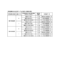
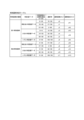
また、詳細は後述するが、時短遊技状態には、A時短遊技状態とB時短遊技状態とC時
短遊技状態とが含まれている。そして、例えば、第1時短報知用表示部168aと第2時
短報知用表示部168bとによる点灯または消灯の組合せによって、いずれの時短遊技状
態であるかを把握できるように構成されている。
In addition, although details will be described later, the time-saving game state includes a time-saving game state A, a time-saving game state B, and a time-saving game state C. And, for example, it is configured so that it is possible to know which time-saving game state is being used by a combination of lighting or extinguishing of the first time-saving
時短報知用表示部168は、実行中の時短制御に応じて第1時短報知用表示部168a
または/および第2時短報知用表示部168bを点灯させるようにしてもよいが、例えば
、時短制御の実行中であるか否かまたは実行中の時短制御の種類を外観で把握できない態
様(例えば、全消灯、全点灯、実行中の時短制御とはかかわりのない態様)で点灯または
消灯させることで、時短制御の実行中であることや、実行中の時短制御の種類を外観で把
握できないように秘匿にしてもよい。とくに、時短制御の実行中であるか否かについては
外観で把握できる可能性があるが、いずれの時短制御が実行されているかについては外観
で把握することが困難である場合があるため、実行中の時短制御の種類を秘匿とすること
で、興趣を高めることが可能である。
The time-saving
Alternatively/and the second time-saving
ただし、時短制御の実行中に電源が遮断された際、後述するバックアップコンデンサ2
07の機能により、時短制御の実行中であることを示すデータのみならず、実行中の時短
制御の種類を示すデータについても消失しない。よって、時短制御の実行中に電源が遮断
され、その後電源が投入された場合、時短制御中であることや、実行中の時短制御の種類
を外観で把握できる態様で、時短報知用表示部168が点灯または消灯する。
However, when the power supply is cut off during the execution of the time-saving control, the
By the function of 07, not only the data indicating that the time-saving control is being executed, but also the data indicating the type of the time-saving control being executed is not lost. Therefore, if the power is cut off while the time-saving control is being executed and then the power is turned on again, the time-saving
なお、電源が遮断される前に、時短制御の実行中であることや、実行中の時短制御の種
類を外観で把握できないように秘匿にされていた場合であっても、電源が投入された場合
には、時短制御の実行中であることおよび実行中の時短制御の種類を外観で把握できる態
様で、時短報知用表示部168を点灯または/および消灯させるように構成されている。
Furthermore, even if the fact that time-saving control is being executed and the type of time-saving control being executed are concealed so as not to be visible from the outside before the power is cut off, when the power is turned on, the time-saving
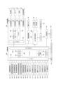
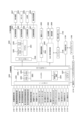
[1-2.電気的構成]
次に、図6を参照して、第1のパチンコ遊技機の制御回路について説明する。図6は、
第1のパチンコ遊技機の制御回路を示すブロック図の一例である。
[1-2. Electrical configuration]
Next, the control circuit of the first pachinko gaming machine will be described with reference to FIG.
2 is an example of a block diagram showing a control circuit of the first pachinko gaming machine;
図6に示されるように、第1のパチンコ遊技機は、主に、遊技の制御を行う主制御回路
200と、遊技の進行に応じた演出の制御を行うサブ制御回路300と、払出・発射制御
回路400と、電源供給回路450と、から構成される。
As shown in FIG. 6, the first pachinko game machine is mainly composed of a
[1-2-1.主制御回路]
主制御回路200は、例えば電源投入時に実行される処理や遊技動作にかかわる処理等
を制御するものであって、メインCPU201、メインROM202(読み出し専用メモ
リ)、メインRAM203(読み書き可能メモリ)、初期リセット回路204およびバッ
クアップコンデンサ207等を備えており、主基板ケース(不図示)内に収容されている
。
[1-2-1. Main control circuit]
The
メインCPU201には、メインROM202、メインRAM203および初期リセッ
ト回路204等が接続される。メインCPU201は、動作を監視するWDT(watchdog
timer)や不正を防止するための機能等が内蔵されている。
A
It also has built-in functions such as a password timer and fraud prevention features.
メインROM202には、メインCPU201により第1のパチンコ遊技機の動作を制
御するためのプログラムや、各種のテーブル等が記憶されている。メインCPU201は
、メインROM202に記憶されたプログラムに従って、各種の処理を実行する機能を有
する。
The
メインRAM203には、遊技の進行に必要な各種データを記憶する記憶領域が設けら
れている。このメインRAM203は、メインCPU201の一時記憶領域として、種々
のフラグや変数の値を記憶する機能を有する。なお、本実施例においては、メインCPU
201の一時記憶領域としてRAMを用いているが、これに限らず、読み書き可能な記憶
媒体であればよい。
The
Although a RAM is used as the
初期リセット回路204は、メインCPU201を監視し、必要に応じてリセット信号
を出力するものである。
The
バックアップコンデンサ207は、電断時等に、メインRAM203に格納されている
データが消失しないように一時的に電力を供給する機能を有するものである。
The
さらに、主制御回路200は、各種デバイス等との間で通信可能に接続されるI/Oポ
ート205、および、サブ制御回路300に対して各種コマンドを出力可能に接続される
コマンド出力ポート206等も備える。
Furthermore, the
また、主制御回路200には、各種のデバイスが接続されている。例えば、主制御回路
200には、上述した普通図柄表示部161、普通図柄用保留表示部162、第1特別図
柄表示部163、第2特別図柄表示部164、第1特別図柄用保留表示部165、第2特
別図柄用保留表示部166、確変報知用表示部167、時短報知用表示部168、普電用
ソレノイド148、および、特電用ソレノイド135等が接続されている。また、主制御
回路200には、これらの他、性能表示モニタ170およびエラー報知モニタ172等も
接続されている。主制御回路200は、I/Oポート205を介して信号を送信すること
により、これらのデバイスの動作を制御することができる。
In addition, various devices are connected to the
性能表示モニタ170には、メインCPU201の制御により性能表示データや後述す
る設定値等が表示される。性能表示データは、例えば、所定数(例えば60000個)の
遊技球の発射に対して大当り遊技状態以外の遊技状態で払い出された遊技球の割合を示す
データであり、ベース値とも呼ばれる。
The performance display monitor 170 displays performance display data and setting values (described later) under the control of the
エラー報知モニタ172には、エラーコードが表示される。また、エラー報知モニタ1
72には、エラーコードの他に、例えば後述する設定機能付きのパチンコ遊技機であれば
、設定変更処理中であることを示す設定変更中コード、設定確認処理中であることを示す
設定確認中コード等を表示することもできる。なお、設定変更中コードとしては、特別図
柄の表示として通常では表示することのない図柄(例えば、設定変更中であることを示す
設定変更図柄)を表示するようにしてもよい。
The error notification monitor 172 displays an error code.
In addition to the error code, for example, in the case of a pachinko machine with a setting function described later, a setting change code indicating that a setting change process is in progress, a setting confirmation code indicating that a setting confirmation process is in progress, etc. may be displayed on 72. Note that, as the setting change code, a symbol that is not normally displayed as a special symbol display (for example, a setting change symbol indicating that a setting change is in progress) may be displayed.
また、主制御回路200には、第1始動口スイッチ121、第2始動口スイッチ141
、通過ゲートスイッチ127、カウントスイッチ132、および、一般入賞口スイッチ1
23等も接続されている。これらのスイッチが検出されると、検出信号がI/Oポート2
05を介して主制御回路200に出力される。
In addition, the
, the
When these switches are detected, a detection signal is sent to I/
05 to the
さらに、主制御回路200には、ホール係員を呼び出す機能や大当り回数を表示する機
能等を有する呼出装置(不図示)、ホール全体のパチンコ遊技機を管理するホールコンピ
ュータ186にデータ送信する際に用いる外部端子板184、後述する設定機能付きのパ
チンコ遊技機であれば設定値を変更したり確認したりする際に操作される設定キー174
、メインRAM203に格納されるバックアップデータを遊技場の管理者の操作に応じて
クリアすることが可能なバックアップクリアスイッチ176等が接続されている。本実施
例において、バックアップクリアスイッチ176は、後述する設定値を変更する際のスイ
ッチも兼用しているが、これに限られず、設定値を変更するための設定スイッチを設ける
ようにしてもよい。
Furthermore, the
A backup clear switch 176 is connected to the
また、設定キー174およびバックアップクリアスイッチ176は、遊技場の管理者以
外の第三者(例えば遊技者)が容易に触ることができないように、所定のケース内に収容
されていることが好ましい。「所定のケース内」には、当該ケースを開放しないと設定キ
ー174やバックアップクリアスイッチ176に接触できない構成のものだけでなく、当
該ケースの設定キー174およびバックアップクリアスイッチ176の対応箇所にのみ切
欠きが設けられ、遊技場の管理者が管理する鍵を使用して島設備からパチンコ遊技機を回
動させて背面を露出させたときに、遊技場の管理者が設定キー174または/およびバッ
クアップクリアスイッチ176に接触できるように構成されているものも含まれる。
Moreover, the setting
なお、本実施例では、設定キー174およびバックアップクリアスイッチ176は、主
制御回路200に接続されているが、これに限られず、例えば、払出・発射制御回路40
0や電源供給回路450に接続されるような構成にしてもよい。この場合にもまた、遊技
場の管理者以外の第三者が設定キー174やバックアップクリアスイッチ176に容易に
接触できないようにすることが好ましい。
In this embodiment, the setting
0 or the
[1-2-2.サブ制御回路]
サブ制御回路300は、サブCPU301、プログラムROM302、ワークRAM3
03、表示制御回路304、音声制御回路305、LED制御回路306、役物制御回路
307およびコマンド入力ポート308等を備える。サブ制御回路300は、主制御回路
200からの指令に応じて遊技の進行に応じた演出を実行する。なお、図6には示されて
いないが、サブ制御回路300には、遊技者が操作可能な演出ボタン54(図1参照)等
も接続されている。
[1-2-2. Sub-control circuit]
The
6, the
プログラムROM302には、サブCPU301により第1のパチンコ遊技機の遊技演
出を制御するためのプログラムや、各種のテーブル等が記憶されている。サブCPU30
1は、プログラムROM302に記憶されたプログラムに従って、各種の処理を実行する
機能を有する。特に、サブCPU301は、主制御回路200から送信される各種のコマ
ンドに従って、遊技演出にかかる制御を行う。
The
The
ワークRAM303は、サブCPU301の一時記憶領域として種々のフラグや変数の
値を記憶する機能を有する。
The
表示制御回路304は、表示装置7における表示制御を行うための回路である。表示制
御回路304は、画像データプロセッサ(以下、VDPと称する)や、各種の画像データ
を生成するためのデータが記憶されている画像データROM、画像データを一時的に格納
するフレームバッファ、画像データを画像信号として変換するD/Aコンバータ等を備え
る。
The
表示制御回路304は、サブCPU301からの画像表示命令に応じて、表示装置7に
表示させるための画像データを一時的にフレームバッファに格納する。なお、表示装置7
に表示させるための画像データには、装飾図柄を示す装飾図柄画像データ、背景画像デー
タ、演出用画像データ等の、遊技に関する各種の画像データが含まれる。
The
The image data to be displayed includes various image data related to the game, such as decorative pattern image data showing decorative patterns, background image data, and image data for effects.
そして、表示制御回路304は、所定のタイミングで、フレームバッファに格納された
画像データをD/Aコンバータに供給する。D/Aコンバータは、画像データを画像信号
として変換し、当該変換した画像信号を所定のタイミングで表示装置7に供給する。表示
装置7に画像信号が供給されると、表示装置7に当該画像信号に関する画像が表示される
。こうして、表示制御回路304は、表示装置7に遊技に関する画像を表示させる制御を
行うことができる。
Then, the
音声制御回路305は、スピーカ32から発生させる音声に関する制御を行うための回
路である。音声制御回路305は、音声に関する制御を行う音源ICや、各種の音声デー
タを記憶する音声データROM、音声信号を増幅するための増幅器(以下、AMPと称す
る)等を備える。
The
音源ICは、スピーカ32から出力される音声の制御を行う。音源ICは、サブCPU
301からの音声発生命令に応じて、音声データROMに記憶されている複数の音声デー
タから一つの音声データを選択する。また、音源ICは、選択された音声データを音声デ
ータROMから読み出し、音声データを所定の音声信号に変換し、当該変換した音声信号
をAMPに供給する。AMPは、スピーカ32から出力される音声や効果音等の信号を増
幅させるものである。
The sound source IC controls the sound output from the
In response to a voice generation command from the
LED制御回路306は、装飾LED等を含むLED群46の制御を行うための回路で
ある。LED制御回路306は、LED制御信号を供給するためのドライブ回路や、複数
種類のLED装飾パターンが記憶されている装飾データROM等を備える。
The
役物制御回路307は、各役物(例えば、演出用役物群58のうちの一または複数の役
物)の動作を制御するための回路である。役物制御回路307は、各役物に対して、駆動
信号を供給するための駆動回路や、点灯制御信号を供給するための点灯回路、動作パター
ンや点灯パターンが記憶されている役物データROM等を備える。
The
また、役物制御回路307は、サブCPU301からの役物作動命令に応じて、役物デ
ータROMに記憶されている複数の動作パターンから一つの動作パターンを選択する。そ
して、選択した動作パターンを役物データROMから読み出し、読み出した動作パターン
に対応する駆動信号を供給することにより、各役物の機械的な動作を制御する。また、点
灯回路は、サブCPU301からの点灯命令に基づいて、役物データROMに記憶されて
いる複数の点灯パターンから一つの点灯パターンを選択する。そして、選択した点灯パタ
ーンを役物データROMから読み出し、読み出した点灯パターンに対応する点灯制御信号
を供給することにより、各役物の点灯動作を制御する。
In addition, the
コマンド入力ポート308は、コマンド出力ポート206と接続されており、主制御回
路200から送信された各種コマンドを受信するものである。
The
[1-2-3.払出・発射制御回路]
払出・発射制御回路400は、賞球や貸球の払い出しを制御するものであり、この払出
・発射制御回路400には、遊技球を払い出すことが可能な払出装置82、遊技球を発射
させることが可能な発射装置6、球貸しにかかる制御を実行可能なカードユニット180
等が接続されている。
[1-2-3. Payout/launch control circuit]
The payout/
etc. are connected.
払出・発射制御回路400は、主制御回路200から送信される賞球制御コマンドを受
信すると、払出装置82に対して所定の信号を送信し、払出装置82に遊技球を払い出さ
せる制御を行う。
When the payout/
カードユニット180には、球貸し操作パネル182が接続されている。球貸し操作パ
ネル182には、球貸しを受けるための球貸しボタンや、キャッシュデータが記憶されて
いる球貸しカードの返却を受けるための貸出返却ボタン(いずれも不図示)が設けられて
いる。例えば遊技者によって球貸し操作が行われると、球貸し操作に応じた貸し球制御信
号がカードユニット180に送信される。払出・発射制御回路400は、カードユニット
180から送信された貸し球制御信号に基づいて、払出装置82に遊技球を払い出させる
制御を行う。なお、操作パネル182は、パチンコ遊技機側に設けられることが多いが、
カードユニット180側に設けられてもよい。
A ball
It may be provided on the
また、払出・発射制御回路400は、発射ハンドル62が時計回りの方向へ回動操作さ
れたことに基づいて、その回動角度(回動量)に応じて発射ソレノイド(図示せず)に電
力を供給し、遊技球を発射させる制御を行う。
In addition, when the launch handle 62 is rotated clockwise, the payout/
[1-2-4.電源供給回路]
電源供給回路450は、遊技に際して必要な電源電圧を、主制御回路200、サブ制御
回路300、払出・発射制御回路400等に供給するために作成する電源回路である。
[1-2-4. Power supply circuit]
The
電源供給回路450には、電源スイッチ95等が接続されている。電源スイッチ95は
、パチンコ遊技機(より詳しくは、主制御回路200、サブ制御回路300、払出・発射
制御回路400等)に必要な電源を供給するときにオン操作するものである。
A
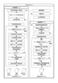
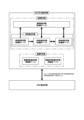
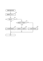
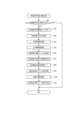
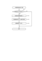
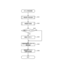
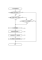
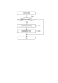
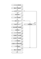
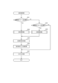
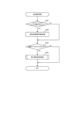
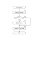
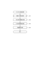
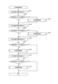
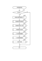
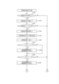
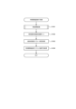
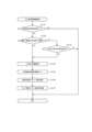
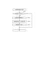
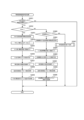
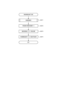
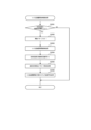
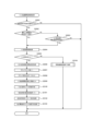
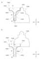
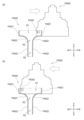
[1-3.遊技フロー]
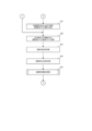
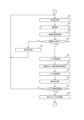
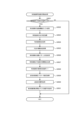
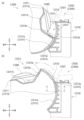
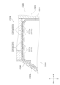
次に、図7および図8を参照して、遊技フローの一例について説明する。図7は、遊技
フローの一例である。図8は、遊技状態の遷移を示す遊技状態遷移図の一例である。なお
、図7に示される遊技フローは、制御上のフローではなく、外観で把握できるフローであ
る。
[1-3. Game flow]
Next, an example of a game flow will be described with reference to Fig. 7 and Fig. 8. Fig. 7 is an example of a game flow. Fig. 8 is an example of a game state transition diagram showing the transition of a game state. Note that the game flow shown in Fig. 7 is not a control flow, but a flow that can be grasped from the outside.
図7に示されるように、パチンコゲームでは、遊技者等のユーザー操作により遊技球が
発射され、その遊技球が各種入賞口(例えば、第1始動口120等)に入賞した場合に遊
技球の払出制御処理が行われる。パチンコゲームには、特別図柄を用いる特別図柄ゲーム
と、普通図柄を用いる普通図柄ゲームとが含まれる。特別図柄ゲームとは、例えば、始動
口120,140への遊技球の入賞に基づいて特別図柄の当り判定処理を実行し、大当り
遊技状態に移行させるか否か等を決定するゲームである。また、普通図柄ゲームとは、例
えば、通過ゲート126への遊技球の通過に基づいて普通図柄の当り判定処理を実行し、
普通電動役物146を作動させて入賞口(本実施例では第2始動口140)を開放状態と
するか否か等を決定するゲームである。なお、この明細書において、「特別図柄ゲーム」
を「遊技」と称する場合もあるが、「遊技」は広い概念で用いられる用語であり、例えば
、普通図柄ゲームや演出ボタン54等の操作部(例えば図1参照)を使用する演出上のゲ
ーム等も「遊技」に含まれる。
As shown in FIG. 7, in a pachinko game, a game ball is launched by a user operation such as a player, and when the game ball enters one of the various winning ports (for example, the
This is a game in which the player determines whether or not to operate the normal
Although these are sometimes referred to as "games,""games" is a term used in a broad sense, and for example, normal symbol games and games with effects that use operating units such as effect button 54 (see, for example, Figure 1) are also included in "games."
また、この明細書において、特別図柄の可変表示が開始されてから、この可変表示が終
了して特別図柄の当り判定処理の結果が確定表示(導出)されるまで(より詳しくは、特
別図柄確定時間が経過するまで)を1回の特別図柄ゲームとする。ただし、特別図柄の当
り判定処理の結果が導出された後、大当り遊技状態に制御された場合は、大当り遊技状態
の終了までを1回の特別図柄ゲームとする。なお、第1のパチンコ遊技機では小当りが特
別図柄の当り判定処理の結果に含まれないが、小当りが特別図柄の当り判定処理の結果に
含まれるパチンコ遊技機では、特別図柄の当り判定処理の結果が導出された後、小当り遊
技状態に制御された場合、小当り遊技状態の終了までを1回の特別図柄ゲームとする。
In this specification, one special symbol game is defined as the period from when the variable display of the special symbol starts until the variable display ends and the result of the special symbol hit determination process is displayed (derived) (more specifically, until the special symbol determination time has elapsed). However, if the result of the special symbol hit determination process is derived and the game is controlled to a big hit game state, one special symbol game is defined as the period until the end of the big hit game state. Note that, in the first pachinko game machine, a small hit is not included in the result of the special symbol hit determination process, but in the pachinko game machine in which a small hit is included in the result of the special symbol hit determination process, one special symbol game is defined as the period until the end of the small hit game state when the game is controlled to a small hit game state after the result of the special symbol hit determination process is derived.
特別図柄ゲームにおいて大当りを示す停止表示態様が第1特別図柄表示部163または
第2特別図柄表示部164に導出されると、大当り遊技状態に制御される。大当り遊技状
態では、特別電動役物133の作動によって大入賞口131が所定時間(例えば最大30
000msec)にわたって開放状態となるラウンド遊技が実行され、大入賞口131へ
の入賞可能性が相対的に高められる。
When a stop display mode indicating a jackpot in the special symbol game is derived to the first special
A round game is played in which the
また、普通図柄ゲームにおいて普通図柄当りを示す停止表示態様が普通図柄表示部16
1に導出されると、普通電動役物146の作動によって入賞口(例えば、本実施例では第
2始動口140)が開放状態となり、例えば第2始動口140への入賞可能性が相対的に
高められる。
In addition, in the normal symbol game, the stop display mode indicating the normal symbol win is set to the normal
When the ball is led out to 1, the winning hole (for example, the
なお、パチンコゲームにおいて実行可能なゲームは、特別図柄ゲームおよび普通図柄ゲ
ームに限られず、これらとは別の新たなゲームを実行可能であってもよい。
It should be noted that games that can be executed in a pachinko game are not limited to special symbol games and normal symbol games, and new games different from these may also be executable.
以下、特別図柄ゲームおよび普通図柄ゲームの遊技フローの概要を説明する。 The following provides an overview of the game flow for special symbol games and regular symbol games.
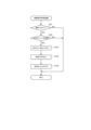
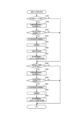
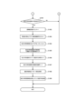
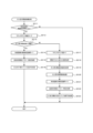
[1-3-1.特別図柄ゲーム]
図7に示されるように、特別図柄ゲームには、主として、第1始動口120または第2
始動口140への入賞(通過)があった場合に行われる特別図柄始動入賞処理、および、
特別図柄の始動条件が成立したことに基づいて行われる特別図柄制御処理、等が含まれる
。
[1-3-1. Special symbol game]
As shown in FIG. 7, the special symbol game mainly includes a
A special symbol start winning process that is performed when a winning (passing) occurs at the
This includes a special symbol control process that is carried out based on the establishment of a special symbol starting condition.
第1始動口120または第2始動口140への遊技球の入賞があった場合、特別図柄始
動入賞処理が行われる。この特別図柄始動入賞処理では、特別図柄用の各種カウンタ(例
えば、大当り判定用カウンタ、図柄決定用カウンタ等)から特別図柄にかかる各種データ
(例えば、大当り判定用乱数値、図柄乱数値、リーチ判定用乱数値、および、演出選択用
乱数値等の各種乱数値等)がそれぞれ抽出(取得)される。抽出された各乱数値は始動情
報として保留される。この特別図柄始動入賞処理は、特別図柄制御処理の実行中であって
も行われる。
When a game ball enters the
また、特別図柄制御処理では、特別図柄の始動条件が成立したか否かが判定される。特
別図柄の始動条件が成立すると、特別図柄の大当り判定用カウンタから抽出された大当り
判定用乱数値を参照し、「大当り」であるか否かを判定する特別図柄の当り判定処理が行
われる。その後、停止図柄を決定する停止図柄決定処理が行われる。停止図柄決定処理で
は、特別図柄の図柄決定用カウンタから抽出された図柄決定用乱数値と、特別図柄の当り
判定処理の結果とを参照し、停止表示させる特別図柄が決定される。
In addition, in the special symbol control process, it is determined whether or not the start condition of the special symbol is satisfied. When the start condition of the special symbol is satisfied, a special symbol hit determination process is performed to determine whether or not there is a "big hit" by referring to a random number value for determining a big hit extracted from a counter for determining a big hit of the special symbol. After that, a stop symbol determination process is performed to determine a stop symbol. In the stop symbol determination process, the special symbol to be stopped is determined by referring to the random number value for determining a symbol extracted from the counter for determining a symbol of the special symbol and the result of the hit determination process of the special symbol.
なお、本実施例では、確変フラグがオンであれば確変制御が実行される。上記の特別図
柄の当り判定処理では、確変フラグがオフの場合は相対的に低い確率で「大当り」である
と判定され、確変フラグがオンの場合は相対的に高い確率で「大当り」であると判定され
る。以下、この明細書において、「大当り」であると判定される確率を「大当り確率」と
称する。
In this embodiment, if the probability variable flag is on, the probability variable control is executed. In the above-mentioned special symbol winning judgment process, if the probability variable flag is off, it is judged to be a "jackpot" with a relatively low probability, and if the probability variable flag is on, it is judged to be a "jackpot" with a relatively high probability. Hereinafter, in this specification, the probability of being judged to be a "jackpot" is referred to as the "jackpot probability."
なお、確変フラグは、メインRAM203に格納される管理フラグの一つであり、確変
制御を実行するか否かを管理するためのフラグである。確変フラグがオンの場合、確変制
御が実行される遊技状態(例えば本実施例では高確時短遊技状態)において遊技が進行す
る。一方、確変フラグがオフの場合、確変制御が実行されない遊技状態(例えば、通常遊
技状態や低確時短遊技状態)において遊技が進行する。
The probability variable flag is one of the management flags stored in the
次いで、特別図柄の変動パターン決定処理が行われる。この処理では、変動パターン決
定用カウンタから乱数値を抽出し、その乱数値と、上述した特別図柄の当り判定処理の結
果と、上述した停止表示させる特別図柄とを参照し、特別図柄の変動パターン(可変表示
パターン)が決定される。そして、特別図柄の変動パターン決定処理の結果に基づいて特
別図柄の可変表示制御処理が行われる。
Next, a process for determining the variation pattern of the special symbols is performed. In this process, a random number is extracted from the variation pattern determination counter, and the variation pattern (variable display pattern) of the special symbols is determined by referring to the random number, the result of the above-mentioned special symbol winning judgment process, and the above-mentioned special symbols to be stopped and displayed. Then, a process for controlling the variable display of the special symbols is performed based on the result of the variation pattern determination process of the special symbols.
特別図柄の変動パターンが決定されると、次に演出パターンを決定するための演出パタ
ーン決定処理が行われる。そして、演出パターン決定処理の結果に基づいて、表示装置7
の表示領域に表示される例えば装飾図柄やキャラクタ演出等の表示演出、および、スピー
カ32から出力される音声や効果音等の音演出等の演出制御処理が行われる。なお、演出
制御処理はサブCPU301によって行われる。
When the variation pattern of the special symbol is determined, a performance pattern determination process is then performed to determine the performance pattern. Then, based on the result of the performance pattern determination process, the
The sub-CPU 301 controls the display of the display area, such as decorative patterns and character effects, and the sound effects, such as voice and sound effects, output from the
そして、特別図柄の可変表示制御処理および演出制御処理が終了し、大当りである場合
、大当り遊技制御処理が行われる。大当り遊技制御処理は、大当り遊技状態において実行
される処理である。大当り遊技状態が終了すると、特別図柄ゲームが終了し、大当りでな
い非大当り遊技状態への遊技状態移行制御処理が行われる。この場合、大当りの種類に応
じて遊技状態が移行する。例えば、確変フラグおよび時短フラグのいずれもがオンにセッ
トされる大当り種類である場合、大当り遊技状態の終了後、高確時短遊技状態に移行する
。
Then, when the special symbol variable display control process and the presentation control process are completed and it is a jackpot, a jackpot game control process is performed. The jackpot game control process is a process executed in a jackpot game state. When the jackpot game state ends, the special symbol game ends, and a game state transition control process to a non-jackpot game state is performed. In this case, the game state transitions according to the type of jackpot. For example, when the jackpot type is one in which both the probability variable flag and the time-saving flag are set to on, the game state transitions to a high probability time-saving game state after the jackpot game state ends.
一方、大当りでないすなわちハズレである場合、特別図柄ゲームが終了する。なお、第
1のパチンコ遊技機では特別図柄の当り判定処理の結果に小当りが含まれないが、特別図
柄の当り判定処理の結果に小当りが含まれるパチンコ遊技機では、小当りに当選すると小
当り遊技制御処理が行われる。また、図7には示されていないが、後述する時短当りであ
る場合は、時短遊技状態に移行する。
On the other hand, if it is not a big win, i.e., if it is a miss, the special symbol game ends. In the first pachinko game machine, the result of the special symbol hit determination process does not include a small win, but in the pachinko game machine in which the result of the special symbol hit determination process includes a small win, a small win game control process is performed when a small win is won. In addition, although not shown in FIG. 7, if it is a time-saving hit, which will be described later, the game moves to a time-saving game state.
そして、特別図柄の始動条件が成立する都度、上述した特別図柄制御処理の各種処理が
繰り返される。
Then, each time the starting condition for the special symbol is satisfied, various processes of the special symbol control process described above are repeated.
なお、特別図柄制御処理中に始動口120,140への遊技球の入賞があった場合、特
別図柄始動入賞処理が実行される。また、始動口120,140への遊技球の入賞時に抽
出される特別図柄の始動情報(例えば、大当り判定用乱数値、特別図柄の図柄乱数値、リ
ーチ判定用乱数値、および、演出選択用乱数値等の各種乱数値等の各種データ)を、特別
図柄の始動条件が成立するまで保留する。
In addition, if a game ball enters the
また、第1のパチンコ遊技機では、第1特別図柄の始動情報の4個と第2特別図柄の始
動情報の4個とで合計最大8個まで特別図柄の始動情報を保留することができるが、保留
できる特別図柄の始動情報の数はこれに限られない。例えば、第1特別図柄の始動情報を
第2特別図柄の始動情報よりも多く保留できるようにしてもよいし、第2特別図柄の始動
情報を第1特別図柄の始動情報よりも多く保留できるようにしてもよい。
In addition, in the first pachinko game machine, the start information of the special symbols can be reserved up to a maximum of eight in total, consisting of four pieces of start information of the first special symbol and four pieces of start information of the second special symbol, but the number of start information of the special symbols that can be reserved is not limited to this. For example, the start information of the first special symbol may be reserved more than the start information of the second special symbol, or the start information of the second special symbol may be reserved more than the start information of the first special symbol.
また、図7には示されていないが、特別図柄が始動入賞してから特別図柄の始動条件が
成立するまでの間に、始動口120,140への遊技球の入賞(通過)時に抽出された始
動情報に基づいて当落(「大当り」当選の有無)や変動パターンを特別図柄の当り判定処
理に先だって判定する先読み判定(例えば、後述の図52のS396を参照)を行い、こ
の先読み判定の結果に基づいて所定の演出を行う先読み演出機能を備えるようにしてもよ
い。なお、上記の先読み判定は、始動口120,140への遊技球の入賞によって抽出さ
れた始動情報が保留される前に行ってもよいし、保留された後に行ってもよい。
Also, although not shown in Fig. 7, a look-ahead determination (see, for example, S396 in Fig. 52 described later) may be performed to determine whether or not a special symbol will win (whether or not a "jackpot" will be won) and the variation pattern prior to the hit determination process of the special symbol based on the start information extracted when the game ball enters (passes) the
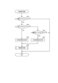
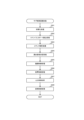
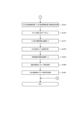
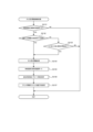
[1-3-2.普通図柄ゲーム]
図7に示されるように、普通図柄ゲームには、主として、通過ゲート126への遊技球
の通過があった場合に行われる普通図柄始動通過処理、および、普通図柄の始動条件が成
立したことに基づいて行われる普通図柄制御処理、等が含まれる。
[1-3-2. Normal symbol game]
As shown in FIG. 7, the normal pattern game mainly includes a normal pattern start passing process which is carried out when the game ball passes through the passing
通過ゲート126への遊技球の通過があった場合、普通図柄始動通過処理が実行される
。この普通図柄始動通過処理では、普通図柄用の当り判定用カウンタから普通図柄の始動
情報(例えば、普通図柄の当り判定用乱数値等)を抽出(取得)し、抽出した始動情報を
保留する。
When the game ball passes through the passing
また、普通図柄制御処理では、メインCPU201は、普通図柄の始動条件が成立した
か否かを判定する。普通図柄の可変表示を開始する場合、メインCPU201は、普通図
柄用の当り判定用カウンタから抽出された普通図柄の当り判定用乱数値を参照し、「普通
図柄当り」とするか否かの普通図柄の当り判定処理を実行し、その後、変動パターン決定
処理を実行する。この処理では、普通図柄の当り判定処理の結果が参照され、普通図柄の
変動パターンが決定される。
In addition, in the normal symbol control process, the
次いで、メインCPU201は、普通図柄の当り判定処理の結果、および、決定された
普通図柄の変動パターンを参照し、普通図柄の可変表示の制御を行う可変表示制御処理、
および、所定の演出を行う演出制御処理を実行する。なお、演出制御処理は実行されない
場合もある。
Next, the
Also, a performance control process is executed to perform a predetermined performance. Note that there are cases where the performance control process is not executed.
そして、普通図柄の可変表示制御処理および演出制御処理が終了すると、メインCPU
201は、「普通図柄当り」を示す普通当り図柄が普通図柄表示部161(図5、図6参
照)に導出されたか否かを判定する。普通当りを示す停止表示態様が導出されたと判定す
ると、メインCPU201は、普通図柄当り遊技制御処理を実行する。この普通図柄当り
遊技制御処理では、普通電動役物146(図4参照)が作動し、入賞口(例えば、本実施
例では例えば第2始動口140(図4参照))への遊技球の入賞(通過)が可能または容
易な開放状態となる。一方、普通当りを示す停止表示態様が導出されなかったと判定する
と、メインCPU201は、普通図柄当り遊技制御処理を実行せず、普通図柄制御処理を
終了する。
Then, when the variable display control process and the performance control process of the normal pattern are completed, the main CPU
201 judges whether or not a normal winning pattern indicating a "normal winning pattern" has been derived to the normal pattern display section 161 (see FIG. 5 and FIG. 6). When it is judged that a stop display mode indicating a normal winning pattern has been derived, the
なお、時短制御が実行されない遊技状態(例えば、通常遊技状態)では、普通当りを示
す停止表示態様が導出される確率を0にしてもよい。時短制御は、時短制御が実行されて
いないときと比べて、特別図柄の可変表示時間を短縮させる特図短縮制御、および、普通
電動役物146を作動させて入賞口(本実施例では例えば第2始動口140(図4参照)
)を開放状態とする頻度を高める電サポ制御、のうち少なくともいずれか一方が行われる
制御が相当する。この時短制御は、特図短縮制御および電サポ制御の両方を行う制御とし
てもよいし、特図短縮制御および電サポ制御のうちいずれか一方のみを行う制御としても
よい。
In addition, in a game state where the time-saving control is not executed (for example, a normal game state), the probability of deriving a stop display mode indicating a normal win may be set to 0. The time-saving control includes a special symbol shortening control that shortens the variable display time of the special symbol compared to when the time-saving control is not executed, and a winning hole (for example, the
This time-saving control may be a control that performs both the special chart shortening control and the electric support control, or a control that performs only one of the special chart shortening control and the electric support control.
電サポ制御は、「普通図柄当り」の当選確率、普通図柄の可変表示時間、および普通電
動役物146の開放パターン(開放回数、開放時間、ウェイト時間)のうち少なくともい
ずれかの時短性能を向上させる制御である。時短性能とは、入賞口(例えば、本実施例で
は第2始動口140(図4参照))への遊技球の入賞の容易さを変更する性能であって、
「普通図柄当り」の当選確率、普通図柄の可変表示時間、または/および普通電動役物1
46の開放パターン(開放回数、開放時間、ウェイト時間等)等をいう。また、時短性能
を向上させるとは、例えば、入賞口(例えば、本実施例では例えば第2始動口140(図
4参照))への遊技球の入賞をより容易にすることである。すなわち、電サポ制御が実行
されると、電サポ制御が実行されていない場合と比べて、「普通図柄当り」の当選確率ア
ップ、普通図柄の可変表示時間の短縮、または/および普通電動役物146による入賞容
易化(開放回数アップ、開放時間延長、ウェイト時間短縮等)が行われる。
The electric support control is a control that improves the time-saving performance of at least one of the winning probability of "normal symbol hit", the variable display time of the normal symbol, and the opening pattern (number of openings, opening time, wait time) of the normal
Probability of winning "normal symbol", variable display time of normal symbol, or/and normal
46 opening patterns (number of openings, opening time, wait time, etc.). In addition, improving the time-saving performance means, for example, making it easier for the game ball to enter the winning hole (for example, in this embodiment, for example, the second starting hole 140 (see FIG. 4)). In other words, when the electric support control is executed, compared to when the electric support control is not executed, the winning probability of "normal symbol hit" is increased, the variable display time of the normal symbol is shortened, and/or winning is made easier by the normal electric role 146 (increasing the number of openings, extending the opening time, shortening the wait time, etc.).
そして、普通図柄の始動条件が成立する都度、上述した普通図柄制御処理の各種処理が
繰り返される。
Then, each time the starting condition for the normal symbol is satisfied, various processes of the normal symbol control process described above are repeated.
なお、普通図柄制御処理中に通過ゲート126への遊技球の通過があった場合、普通図
柄始動通過処理が実行される。また、通過ゲート126への遊技球の通過時に抽出される
普通図柄の始動情報(例えば、普通図柄の当り判定用乱数値等)を、普通図柄の始動条件
が成立するまで保留する。
In addition, when the game ball passes through the passing
なお、普通図柄の可変表示の開始は保留された順に行われ、普通図柄の始動条件が成立
すると、保留されている普通図柄の始動情報のうち最先で保留された始動情報についての
可変表示を実行する。
The variable display of the normal symbols is started in the order in which they are reserved, and when the start condition of the normal symbols is established, the variable display is executed for the start information that was reserved first among the start information of the reserved normal symbols.
なお、各種乱数値(例えば、第1特別図柄の大当り判定用乱数値、第1特別図柄の図柄
乱数値、第1特別図柄のリーチ判定用乱数値、第2特別図柄の大当り判定用乱数値、第2
特別図柄の図柄乱数値、第2特別図柄のリーチ判定用乱数値、および、普通図柄の当り判
定用乱数値等)の抽出方式は、メインCPU201によりプログラムを実行することによ
って所定の範囲(幅)内で乱数値を生成するソフト乱数方式を用いてもよいし、所定周期
で乱数が更新される乱数発生器におけるカウンタから乱数値を抽出するハード乱数方式を
用いてもよい。
In addition, various random number values (for example, a random number value for determining a jackpot of the first special symbol, a random number value for a symbol of the first special symbol, a random number value for determining a reach of the first special symbol, a random number value for determining a jackpot of the second special symbol,
The method of extracting the random number values for the special pattern, the random number value for reach determination of the second special pattern, and the random number value for hit determination of the normal pattern, etc. may use a soft random number method in which random number values are generated within a specified range (width) by executing a program by the
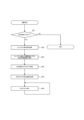
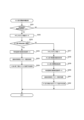
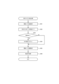
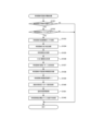
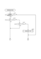
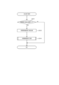
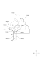
[1-3-3.遊技状態遷移]
図8に示されるように、遊技の状態は、非大当り遊技状態と大当り遊技状態とに大別す
ることができる。非大当り遊技状態では、上述したとおり特別図柄ゲームを実行し、特別
図柄の当り判定処理の結果として大当りが導出されると、非大当り遊技状態から大当り遊
技状態に移行する。大当り遊技状態では、上述したとおりラウンド遊技が実行され、特別
図柄の可変表示は実行されない。ただし、普通図柄の可変表示については、大当り遊技状
態であっても実行可能とされている。なお、小当り遊技状態についての説明は省略するも
のとする。
[1-3-3. Game state transition]
As shown in FIG. 8, the game state can be roughly divided into a non-jackpot game state and a jackpot game state. In the non-jackpot game state, the special symbol game is executed as described above, and when a jackpot is derived as a result of the hit determination process of the special symbol, the game state transitions from the non-jackpot game state to the jackpot game state. In the jackpot game state, the round game is executed as described above, and the variable display of the special symbol is not executed. However, the variable display of the normal symbol can be executed even in the jackpot game state. Note that the explanation of the small jackpot game state will be omitted.
非大当り遊技状態は、特別図柄の当り判定処理における大当りの当選確率が相対的に低
い低確率状態と、特別図柄の当り判定処理における大当りの当選確率が相対的に高い高確
遊技状態と、に大別することができる。
The non-jackpot game state can be broadly divided into a low probability state in which the probability of winning a jackpot in the hit determination process of the special pattern is relatively low, and a high probability game state in which the probability of winning a jackpot in the hit determination process of the special pattern is relatively high.
高確遊技状態には、時短制御が実行される高確時短遊技状態(高確高ベース)が含まれ
る。なお、第1のパチンコ遊技機における高確遊技状態には含まれないが、図8に示され
るように、時短制御が実行されない高確非時短遊技状態(高確低ベース状態)が高確遊技
状態に含まれる場合もある。
The high probability game state includes a high probability time-saving game state (high probability high base) in which time-saving control is executed. Note that, although not included in the high probability game state in the first pachinko game machine, a high probability non-time-saving game state (high probability low base state) in which time-saving control is not executed may be included in the high probability game state, as shown in FIG.
低確率状態には、時短制御が実行されない通常遊技状態(低確低ベース)と、時短制御
が実行される時短遊技状態(低確高ベース)とが含まれる。
The low probability state includes a normal game state (low probability, low base) in which time-saving control is not executed, and a time-saving game state (low probability, high base) in which time-saving control is executed.
さらに、時短遊技状態には、A時短遊技状態と、B時短遊技状態と、C時短遊技状態と
が含まれる。
Furthermore, the time-shortened game state includes a time-shortened game state A, a time-shortened game state B, and a time-shortened game state C.
A時短遊技状態は、特定の大当り遊技状態の終了後に移行可能な時短遊技状態であって
、規定回数の特別図柄ゲームが実行されるか、大当り遊技状態に移行されると、A時短遊
技状態が終了する。規定回数の特別図柄ゲームが実行されることによってA時短遊技状態
が終了すると、原則として、通常遊技状態に移行する。
The time-saving game state A is a time-saving game state to which a player can enter after a specific big win game state ends, and the time-saving game state A ends when a specified number of special symbol games are played or when the player enters the big win game state. When the time-saving game state A ends due to the specified number of special symbol games being played, the player enters the normal game state in principle.
B時短遊技状態は、例えば、大当り遊技状態が終了し、非高確遊技状態(すなわち確変
フラグがオフである遊技状態)における特別図柄の可変表示が開始されたことや、後述す
るRAMクリアされたこと等を起点とする特別図柄の可変表示回数(例えば、天井カウン
タ)が天井値(例えば、1000回)に到達すると移行可能な時短遊技状態であって、規
定回数の特別図柄ゲームが実行されるか、大当り遊技状態に移行されると、B時短遊技状
態が終了する。規定回数の特別図柄ゲームが実行されることによってB時短遊技状態が終
了すると、原則として、通常遊技状態に移行する。
The B time-saving game state is a time-saving game state to which a transition can be made when, for example, a jackpot game state ends and the variable display of special symbols in a non-high probability game state (i.e., a game state in which the probability flag is off) begins, or the number of times the special symbols are variable displayed (e.g., a ceiling counter) reaches a ceiling value (e.g., 1,000 times), which starts from the RAM being cleared as described below, and the B time-saving game state ends when a specified number of special symbol games are played or when a transition is made to the jackpot game state. When the B time-saving game state ends as a result of the specified number of special symbol games being played, a transition to the normal game state occurs, in principle.
C時短遊技状態は、低確率状態において行われた特別図柄の当り判定処理の結果が「時
短当り」であり、時短当りの表示態様が導出されると移行可能な時短遊技状態であって、
「時短当り」に当選したことによって決定された規定回数の特別図柄ゲームが実行される
か、大当り遊技状態に移行されると、C時短遊技状態が終了する。上記の規定回数の特別
図柄ゲームが実行されることによってC時短遊技状態が終了すると、原則として、通常遊
技状態に移行する。なお、例えば、複数の時短遊技状態が重複する場合には、上記の規定
回数の特別図柄ゲームが実行されたとしても、通常遊技状態に移行するのではなくC時短
遊技状態が継続する。
The C time-saving game state is a time-saving game state to which a transition can be made when the result of the hit determination process of the special symbol performed in the low probability state is a "time-saving hit" and the display mode of the time-saving hit is derived,
The time-saving C game state ends when the specified number of special symbol games determined by winning the "time-saving win" are played or when a transition to a big win game state occurs. When the time-saving C game state ends by playing the specified number of special symbol games, a transition to a normal game state occurs in principle. Note that, for example, if multiple time-saving game states overlap, even if the specified number of special symbol games are played, the time-saving C game state continues rather than transitioning to the normal game state.
この明細書において、複数の時短遊技状態を重ねて実行するか否かにかかわらず、時短
遊技状態において時短遊技状態への移行条件が成立したり、複数の時短遊技状態への移行
条件が同時に成立することを、時短遊技状態が「重複する」と称する。そして、複数の時
短遊技状態が重複した場合に、メインCPU201の制御により、内部的に、重複した複
数の時短遊技状態のいずれをも作動させること、すなわち重複した複数の時短遊技状態を
内部的に並行して作動させることを「重ねて実行」すると称する。ただし、メインCPU
201が内部的には複数の時短遊技状態を重ねて実行したとしても、実際に実行される時
短制御はいずれか一方の時短遊技状態に対応する時短制御のみである。すなわち、複数の
時短遊技状態が重ねて実行されている場合であっても、遊技者からは、複数の時短遊技状
態のうちいずれか一の時短遊技状態に制御されているものと把握される。
In this specification, whether or not multiple time-shortened game states are executed in an overlapping manner, the establishment of a transition condition to a time-shortened game state in a time-shortened game state, or the establishment of transition conditions to multiple time-shortened game states simultaneously, is referred to as the time-shortened game states "overlapping." When multiple time-shortened game states overlap, the internal operation of all of the multiple overlapping time-shortened game states under the control of the
Even if 201 internally executes a plurality of time-shortening game states in an overlapping manner, the time-shortening control that is actually executed is only the time-shortening control that corresponds to one of the time-shortening game states. In other words, even if a plurality of time-shortening game states are executed in an overlapping manner, the player understands that the game is being controlled to one of the plurality of time-shortening game states.
次に、遊技状態の移行について説明する。 Next, we will explain how the game state changes.
通常遊技状態、時短遊技状態(A時短遊技状態、B時短遊技状態、C時短遊技状態)、
および高確遊技状態(例えば高確時短遊技状態)に制御されている場合であっても、特別
図柄の当り判定処理の結果が大当りであると、大当り遊技状態に移行する。
Normal game state, time-saving game state (A time-saving game state, B time-saving game state, C time-saving game state),
Even when the game is controlled to a high probability game state (for example, a high probability time-saving game state), if the result of the special symbol hit determination process is a big hit, the game state transitions to a big hit game state.
大当り遊技状態が終了すると、遊技仕様にもよるが、通常遊技状態、時短遊技状態、お
よび高確遊技状態(例えば高確時短遊技状態)のいずれにも移行させることができる。た
だし、大当り遊技状態が終了したときに移行できる時短遊技状態は、A時短遊技状態に限
られる。
When the big win game state ends, depending on the game specifications, the game state can be switched to any of the normal game state, the time-saving game state, and the high probability game state (for example, the high probability time-saving game state). However, the time-saving game state to which the game state can be switched when the big win game state ends is limited to the A time-saving game state.
高確遊技状態に制御されている場合、所謂ST機やループ機等の一部のパチンコ遊技機
を除いて、高確遊技状態から時短遊技状態または通常遊技状態には移行しない。同様に、
時短遊技状態または通常遊技状態からは、大当り遊技状態を経由しない限り、高確遊技状
態には移行しない。
When controlled to the high probability game state, except for some pachinko game machines such as so-called ST machines and loop machines, the high probability game state does not transition to the time-saving game state or the normal game state.
The time-saving game state or the normal game state does not transition to the high probability game state unless the big win game state is passed through.
通常遊技状態に制御されている場合、B時短遊技状態またはC時短遊技状態に移行可能
であるものの、A時短遊技状態には、大当り遊技状態を経由しない限り、移行できない。
ただし、A時短遊技状態において規定回数の特別図柄ゲームが実行されると通常遊技状態
に移行するため、A時短遊技状態から通常遊技状態への移行は可能である。なお、B時短
遊技状態およびC時短遊技状態のいずれに制御されている場合であっても、規定回数の特
別図柄ゲームが実行されると通常遊技状態に移行するため、B時短遊技状態やC時短遊技
状態から通常遊技状態への移行も可能である。
When controlled to the normal game state, it is possible to transition to the time-shortened game state B or the time-shortened game state C, but it is not possible to transition to the time-shortened game state A unless via the jackpot game state.
However, since a transition to the normal game state occurs when a specified number of special symbol games are played in the time-saving game state A, a transition from the time-saving game state A to the normal game state is possible. Note that, regardless of whether the game is controlled in the time-saving game state B or the time-saving game state C, a transition to the normal game state occurs when a specified number of special symbol games are played, so a transition from the time-saving game state B or the time-saving game state C to the normal game state is also possible.
次に、時短遊技状態どうしの移行について説明する。 Next, we will explain how to transition between time-saving play states.
A時短遊技状態に制御されている場合、A時短遊技状態において実行可能な時短回数は
、B時短遊技状態への移行条件である天井値よりも少ない回数に設定されるため、A時短
遊技状態からB時短遊技状態に移行することはない。また、A時短遊技状態は大当り遊技
状態を経由して制御されるため、B時短遊技状態からA時短遊技状態に移行することもな
い。一方、A時短遊技状態における特別図柄の当り判定処理の結果が「時短当り」である
とC時短遊技状態への移行条件が成立するため、A時短遊技状態とC時短遊技状態とが重
複しうる。ただし、上述したようにA時短遊技状態は大当り遊技状態を経由して制御され
るため、C時短遊技状態からA時短遊技状態に移行することはない。
When controlled to the time-saving game state A, the number of time-saving times that can be executed in the time-saving game state A is set to a number less than the ceiling value, which is the transition condition to the time-saving game state B, so there is no transition from the time-saving game state A to the time-saving game state B. Also, since the time-saving game state A is controlled via the jackpot game state, there is no transition from the time-saving game state B to the time-saving game state A. On the other hand, if the result of the hit determination process of the special pattern in the time-saving game state A is a "time-saving hit", the transition condition to the time-saving game state C is established, so the time-saving game state A and the time-saving game state C may overlap. However, as described above, since the time-saving game state A is controlled via the jackpot game state, there is no transition from the time-saving game state C to the time-saving game state A.
B時短遊技状態に制御されている場合、特別図柄の当り判定処理の結果が「時短当り」
であるとC時短遊技状態への移行条件が成立し、B時短遊技状態とC時短遊技状態とが重
複しうる。また、C時短遊技状態において天井カウンタが天井値に到達した場合も、C時
短遊技状態とB時短遊技状態とが重複しうる。
When the game is controlled to the B time-saving game mode, the result of the special symbol hit determination process is "time-saving hit".
If the time-shortened game state is set to the value above, the condition for transition to the time-shortened game state C is met, and the time-shortened game state B and the time-shortened game state C may overlap. Also, if the ceiling counter reaches the ceiling value in the time-shortened game state C, the time-shortened game state C and the time-shortened game state B may overlap.
C時短遊技状態に制御されている場合、特別図柄の当り判定処理の結果が「時短当り」
であるとC時短遊技状態への移行条件が成立し、C時短遊技状態とC時短遊技状態とが重
複しうる。
When the game is controlled in the C time-saving game mode, the result of the special symbol hit determination process is "time-saving hit".
If so, a condition for transition to the C time-shortened gaming state is met, and the C time-shortened gaming state and the C time-shortened gaming state may overlap.
なお、時短遊技状態の重複についての詳細は後述する。 More details about overlapping time-saving game modes will be provided later.
[1-4.基本仕様]
次に、図9~図19を参照して、第1のパチンコ遊技機の基本仕様について説明する。
[1-4. Basic specifications]
Next, the basic specifications of the first pachinko gaming machine will be described with reference to FIG. 9 to FIG.
第1のパチンコ遊技機では、確変制御および時短制御のいずれも実行されない通常遊技
状態、確変制御および時短制御の両方が実行される高確時短遊技状態、並びに、確変制御
は実行されないものの時短制御が実行される低確時短遊技状態が用意されており、メイン
CPU201は、これらの遊技状態のうちいずれかの遊技状態において遊技を進行させる
ことが可能となっている。ただし、メインCPU201の制御によって進行される遊技状
態はこれに限られない。
In the first pachinko game machine, a normal game state in which neither the probability variable control nor the time-saving control is executed, a high probability time-saving game state in which both the probability variable control and the time-saving control are executed, and a low probability time-saving game state in which the probability variable control is not executed but the time-saving control is executed are prepared, and the
本実施例において、通常遊技状態では左打ちが正規な遊技態様とされ、高確時短遊技状
態および低確時短遊技状態では右打ちが正規な遊技態様とされる。サブCPU301は、
正規な遊技態様とされる打ち方を、例えば表示装置7の表示領域に表示する制御を実行す
る。なお、「正規な遊技態様」とは、複数の遊技態様(例えば発射態様)のうち遊技者に
とって最も不利益とならない(遊技者にとって有利な)遊技態様が相当する。
In this embodiment, in the normal game state, left hitting is the regular game mode, and in the high probability time-saving game state and the low probability time-saving game state, right hitting is the regular game mode.
The control is executed to display the hitting manner considered to be the regular game mode, for example, in the display area of the
[1-4-1.設定値毎の大当り確率]
図9は、第1のパチンコ遊技機における設定値毎の大当り確率(概算)を示すテーブル
の一例である。図9に示されるように、第1のパチンコ遊技機では、上述の設定キー17
4やバックアップクリアスイッチ176(いずれも図6参照)等を用いて、例えば設定1
~設定6といった複数の設定値のうちいずれか一の設定値にセットすることができる。こ
のような設定機能付きパチンコ遊技機の場合、大当り確率は設定値に応じて異なっており
、メインCPU201は、セットされた設定値に基づいて特別図柄の当り判定処理を実行
する。
[1-4-1. Jackpot Probability for Each Setting Value]
9 is an example of a table showing the probability of winning (approximate) for each setting value in the first pachinko gaming machine. As shown in FIG. 9, in the first pachinko gaming machine, the setting
4 or backup clear switch 176 (see FIG. 6) to set, for example, setting 1
The setting value can be set to any one of a plurality of setting values, such as setting 1 through setting 6. In the case of such a pachinko game machine with a setting function, the probability of a big win differs according to the setting value, and the
具体的には、確変制御が実行されない確変フラグがオフの遊技状態(本実施例では例え
ば通常遊技状態および低確時短遊技状態)における大当り確率は、第1特別図柄の当り判
定処理および第2特別図柄の当り判定処理のいずれが実行された場合であっても、例えば
、設定1で約319分の1、設定2で約314分の1、設定3で約309分の1、設定4
で約304分の1、設定5で約299分の1、設定6で約294分の1となっている。ま
た、確変制御が実行される確変フラグがオンの遊技状態(本実施例では例えば高確時短遊
技状態)における大当り確率は、設定1で約77分の1、設定2で約76分の1、設定3
で約75分の1、設定4で約74分の1、設定5で約73分の1、設定6で約72分の1
となっている。
Specifically, the probability of a jackpot in a game state in which the probability jackpot control is not executed and the probability jackpot flag is off (for example, in the normal game state and the low probability time-saving game state in this embodiment), regardless of whether the hit determination process for the first special symbol or the hit determination process for the second special symbol is executed, is, for example, about 1 in 319 in setting 1, about 1 in 314 in setting 2, about 1 in 309 in setting 3, and about 1 in 4 in setting 5.
In the case of setting 1, the probability of winning is about 1 in 304, in the case of setting 5, the probability of winning is about 1 in 299, and in the case of setting 6, the probability of winning is about 1 in 77 in setting 1, about 1 in 76 in setting 2, and about 1 in 304 in setting 3. In the case of setting 4, the probability of winning is about 1 in 77 in setting 5, about 1 in 76 in setting 6, and about 1 in 304 in setting 7. In the case of setting 8, the probability of winning is about 1 in 77 in setting 1, about 1 in 76 in setting 2, and about 1 in 304 in setting 3.
1 in 75 at setting 4, 1 in 74 at setting 5, 1 in 73 at setting 6, 1 in 72 at setting
It is as follows.
なお、時短当り確率は、大当り確率とは異なり全設定値で共通の確率となっている。例
えば、第1特別図柄の当り判定処理が実行された場合の時短当り確率は160分の1、第
2特別図柄の当り判定処理が実行された場合の時短当り確率は240分の1となっている
。時短当り確率は、第1特別図柄の当り判定処理が実行された場合と第2特別図柄の当り
判定処理が実行された場合とで異ならせてもよいが、同じとしてもよい。
The time-saving hit probability is the same probability for all settings, unlike the jackpot probability. For example, the time-saving hit probability when the hit determination process for the first special symbol is executed is 1 in 160, and the time-saving hit probability when the hit determination process for the second special symbol is executed is 1 in 240. The time-saving hit probability may be different when the hit determination process for the first special symbol is executed and when the hit determination process for the second special symbol is executed, or may be the same.
ただし、時短当り確率が全設定値で共通の確率であったとしても、時短継続率(例えば
、セットされる時短回数)については、設定値に応じて異ならせてもよい。例えば、特別
図柄の当り判定処理の結果が「時短当り」である場合、例えば、設定1の場合は時短回数
として50回がセットされ、設定6の場合は時短回数として100回がセットされるよう
にしてもよい。
However, even if the probability of winning the time-saving function is the same for all the settings, the time-saving function continuation rate (for example, the number of times the time-saving function is set) may be different depending on the setting value. For example, if the result of the hit determination process for the special symbol is a "time-saving function hit," the number of times the time-saving function may be set to 50 in the case of setting 1, and 100 in the case of setting 6.
なお、第1のパチンコ遊技機では小当りが抽選対象に含まれていないが、小当りを抽選
対象に含むようにしてもよい。小当りを抽選対象に含む場合、小当り確率を、全設定値で
共通の確率とするとよい。また、小当りを抽選対象に含む場合、第1特別図柄と第2特別
図柄とのうち一方の特別図柄(例えば第2特別図柄)の当り判定処理が行われた場合に限
り小当りに当選しうるようにしてもよい。この場合、他方の特別図柄(例えば第1特別図
柄)の当り判定処理では、小当り当選したか否かの判定自体を行わない態様の他、小当り
確率を0として小当り当選したか否かの判定を行う態様であってもよい。
In the first pachinko game machine, the small win is not included in the lottery, but the small win may be included in the lottery. When the small win is included in the lottery, the small win probability may be a common probability for all set values. Also, when the small win is included in the lottery, the small win may be won only when the hit determination process of one of the first special pattern and the second special pattern (for example, the second special pattern) is performed. In this case, in the hit determination process of the other special pattern (for example, the first special pattern), in addition to a mode in which the determination of whether or not the small win has been won is not performed, a mode in which the small win probability is set to 0 and whether or not the small win has been won may be performed.
上記の時短当り確率および小当りを抽選対象に含む場合の小当り確率は、上述したとお
り全設定値で共通の確率となっているが、これに限られず、設定値に応じて異なる確率と
してもよい。
As described above, the above-mentioned time-saving hit probability and the small hit probability when small hits are included in the lottery targets are the same probability for all setting values, but are not limited to this and may be different probabilities depending on the setting value.
また、本実施例では、全ての設定値においてそれぞれ大当り確率が異なっているが、こ
れに限定されず、例えば、設定1と設定2とで共通の大当り確率、設定3と設定4とで共
通の大当り確率、設定5と設定6とで共通の大当り確率といったように、複数の設定値で
大当り確率を同じにしてもよい。
In addition, in this embodiment, the probability of a jackpot is different for each setting value, but this is not limited to this. For example, the probability of a jackpot may be the same for multiple setting values, such as a common jackpot probability for
また、本実施例では、設定値に応じて大当り確率が異なっているが、遊技者にとっての
有利度合いが設定値に応じて異なれば、設定値に応じて異なる対象が必ずしも大当り確率
に限定されない。例えば、特定の入賞口に遊技球が入賞すると大当り遊技状態に制御され
るようなパチンコ遊技機であれば、設定値に応じて特定の入賞口への入賞確率を異ならせ
るようにしてもよい。なお、パチンコ遊技機を、設定機能付きパチンコ遊技機とすること
は必須ではない。
In this embodiment, the probability of winning a jackpot is different depending on the setting value, but if the degree of advantage for the player differs depending on the setting value, the target that differs depending on the setting value is not necessarily limited to the probability of winning a jackpot. For example, in a pachinko game machine that is controlled to a jackpot game state when a game ball enters a specific winning hole, the probability of winning a prize in the specific winning hole may be made different depending on the setting value. Note that it is not essential that the pachinko game machine be a pachinko game machine with a setting function.
[1-4-2.特別図柄の当り判定テーブル]
図10は、第1のパチンコ遊技機が備える主制御回路200のメインROM202に記
憶されている特別図柄の当り判定テーブルの一例である。なお、図10に示される特別図
柄の当り判定テーブルは、図9に示される設定1の場合を一例として示したものである。
[1-4-2. Special symbol winning judgment table]
10 is an example of a special symbol winning judgment table stored in the
特別図柄の当り判定テーブルは、特別図柄の当り判定処理において参照されるテーブル
、すなわち、始動口120,140に遊技球が入賞した際に抽出される大当り判定用乱数
値に基づいて「時短当り」、「大当り」または「ハズレ」を抽選により決定する際に参照
されるテーブルである。なお、本実施例では、抽選対象は「時短当り」、「大当り」およ
び「ハズレ」であり、他の抽選対象(例えば、小当り)が含まれていないが、第1始動口
120または/および第2始動口140に遊技球が入賞した際に、他の抽選対象に決定さ
れるようにしてもよい。
The special symbol winning judgment table is a table referred to in the winning judgment process of the special symbol, that is, a table referred to when determining by lottery whether a "time-saving winning", a "jackpot", or a "miss" is a winning result based on a random number value for winning judgment extracted when a game ball enters the
大当り判定用乱数値は、上述したとおり、特別図柄の当り判定処理に用いられる乱数値
である。本実施例において、大当り判定用乱数値は、0~65535(65536種類)
の中から抽出される。ただし、発生する乱数値の範囲は上記に限られない。
As described above, the random number value for determining a jackpot is a random number value used in the process of determining whether or not a special symbol is selected. In this embodiment, the random number value for determining a jackpot is 0 to 65535 (65536 types).
However, the range of the generated random numbers is not limited to the above.
本実施例では、メインCPU201は、第1特別図柄の当り判定処理において、抽出さ
れた大当り判定用乱数値に基づいて「時短当り」、「大当り」、または「ハズレ」に決定
する。第1特別図柄の当り判定テーブルには、確変フラグの値(0または1)毎に、「時
短当り」に決定される大当り判定用乱数値の範囲(幅)とこれに対応する時短当り判定値
データとの関係、「大当り」に決定される大当り判定用乱数値の範囲(幅)とこれに対応
する大当り判定値データとの関係、および「ハズレ」に決定される大当り判定用乱数値の
範囲(幅)とこれに対応するハズレ判定値データとの関係が規定されている。
In this embodiment, the
なお、本明細書において、確変フラグの値が「0」の場合、確変フラグがオフであり、
確変フラグの値が「1」の場合、確変フラグがオンである。
In this specification, when the value of the probability flag is "0", the probability flag is off,
When the value of the probability variable flag is "1", the probability variable flag is on.
また、メインCPU201は、第2特別図柄の当り判定処理において、第1特別図柄の
当り判定処理と同様、抽出された大当り判定用乱数値に基づいて「時短当り」、「大当り
」、または「ハズレ」に決定する。第2特別図柄の当り判定テーブルには、確変フラグの
値(0または1)毎に、「時短当り」に決定される大当り判定用乱数値の範囲(幅)とこ
れに対応する時短当り判定値データとの関係、「大当り」に決定される大当り判定用乱数
値の範囲(幅)とこれに対応する大当り判定値データとの関係、および「ハズレ」に決定
される大当り判定用乱数値の範囲(幅)とこれに対応するハズレ判定値データとの関係が
規定されている。
In addition, in the hit determination process for the second special symbol, the
本実施例では、例えば、第1特別図柄の当り判定処理時に確変フラグがオフであって、
抽出された大当り判定用乱数値が0~408のいずれかである場合、メインCPU201
は、「時短当り」と判定し、当落判定値データを「時短当り判定値データ」に決定する。
また、第1特別図柄の当り判定処理時に確変フラグがオフであって、抽出された大当り判
定用乱数値が409~613のいずれかである場合、メインCPU201は、「大当り」
と判定し、当落判定値データを「大当り判定値データ」に決定する。また、抽出された大
当り判定用乱数値が614~65535のいずれかである場合、メインCPU201は、
「ハズレ」と判定し、判定値データを「ハズレ判定値データ」に決定する。
In this embodiment, for example, when the winning judgment process of the first special symbol is performed, the probability of winning flag is OFF,
If the extracted random number for determining a big win is any one of 0 to 408, the
is judged as a "time-saving hit" and the hit/loss judgment value data is determined to be the "time-saving hit judgment value data."
In addition, when the probability of winning flag is OFF during the winning judgment process of the first special symbol, and the extracted random number value for the big win judgment is any one of 409 to 613, the
If the extracted random number value for jackpot determination is any one of 614 to 65535, the
It is judged as "miss", and the judgment value data is determined as "miss judgment value data".
また、例えば、第1特別図柄の当り判定処理時に確変フラグがオンであって、抽出され
た大当り判定用乱数値が0~408のいずれかである場合、メインCPU201は、「時
短当り」と判定し、判定値データを「時短当り判定値データ」に決定する。また、第1特
別図柄の当り判定処理時に確変フラグがオンであって、抽出された大当り判定用乱数値が
409~1259のいずれかである場合、メインCPU201は、「大当り」と判定し、
判定値データを「大当り判定値データ」に決定する。また、抽出された大当り判定用乱数
値が1260~65535のいずれかである場合、メインCPU201は、「ハズレ」と
判定し、判定値データを「ハズレ判定値データ」に決定する。
Also, for example, if the probability variable flag is on during the hit determination process of the first special symbol and the extracted random number value for the big hit determination is any one of 0 to 408, the
The
同様に、例えば、第2特別図柄の当り判定処理時に確変フラグがオフであって、抽出さ
れた大当り判定用乱数値が0~272のいずれかである場合、メインCPU201は、「
時短当り」と判定し、判定値データを「時短当り判定値データ」に決定する。また、第2
特別図柄の当り判定処理時に確変フラグがオフであって、抽出された大当り判定用乱数値
が273~477のいずれかである場合、メインCPU201は、「大当り」と判定し、
判定値データを「大当り判定値データ」に決定する。さらに、第2特別図柄の当り判定処
理時に確変フラグがオフであって、抽出された大当り判定用乱数値が478~65535
のいずれかである場合、メインCPU201は、「ハズレ」と判定し、判定値データを「
ハズレ判定値データ」に決定する。
Similarly, for example, when the probability of winning flag is OFF during the winning determination process of the second special symbol, and the extracted random number value for the winning determination is any one of 0 to 272, the
The second judgment value data is determined to be "time-saving hit judgment value data".
When the probability of winning is increased by 100%, the probability of winning is increased by 100%. When the probability of winning is increased by 100%, the probability of winning is increased by 100%. When the probability of winning is increased by 100%, the probability of winning is increased by 100%.
The judgment value data is determined as "jackpot judgment value data". Furthermore, when the probability variable flag is off during the hit judgment process of the second special symbol, the extracted random number value for jackpot judgment is 478 to 65535.
If the result is either of the above, the
The "miss judgment value data" is determined.
また、例えば、第2特別図柄の当り判定処理時に確変フラグがオンであって、抽出され
た大当り判定用乱数値が0~272のいずれかである場合、メインCPU201は、「時
短当り」と判定し、判定値データを「時短当り判定値データ」に決定する。また、第2特
別図柄の当り判定処理時に確変フラグがオンであって、抽出された大当り判定用乱数値が
273~1123のいずれかである場合、メインCPU201は、「大当り」と判定し、
判定値データを「大当り判定値データ」に決定する。さらに、第2特別図柄の当り判定処
理時に確変フラグがオンであって、抽出された大当り判定用乱数値が1124~6553
5のいずれかである場合、メインCPU201は、「ハズレ」と判定し、判定値データを
「ハズレ判定値データ」に決定する。
Also, for example, if the probability variable flag is on during the hit determination process of the second special symbol and the extracted random number value for the big hit determination is any one of 0 to 272, the
The judgment value data is determined as "jackpot judgment value data". Furthermore, when the winning judgment process of the second special symbol is performed, the probability variable flag is on and the extracted random number value for jackpot judgment is 1124 to 6553.
If the result is any of the above, the
このように、本実施例では、例えば0~65535の範囲で発生する大当り判定用乱数
値のうち、0から所定幅(例えば、第1特別図柄の当り判定処理であれば0~408)を
、大当り判定値データおよびハズレ判定値データを除く他の判定値データ(例えば、時短
当り判定値データ)に割り当てている。また、所定値から最後尾(例えば、第1特別図柄
の当り判定処理時に確変フラグがオフの場合であれば614~65535)をハズレ判定
値データに割り当てている。さらに、大当り判定値データとハズレ判定値データとを隣接
して割り当てている。このようにすることで、例えば確変フラグがオフからオン(または
オンからオフ)になった場合に、大当り判定値データの幅を大きく(または小さく)した
分だけハズレ判定値データの幅を小さく(または大きく)するだけで、他の判定値データ
(例えば、時短当り判定値データ)の幅を変更することなく、大当り確率を変更すること
が可能となる。
In this embodiment, for example, among the random numbers for determining a jackpot that are generated in the range of 0 to 65535, a predetermined range from 0 (for example, 0 to 408 in the case of the hit determination process of the first special symbol) is assigned to the other determination value data (for example, time-saving hit determination value data) excluding the jackpot determination value data and the miss determination value data. In addition, the end of the predetermined range (for example, 614 to 65535 in the case of the probability variable flag being off during the hit determination process of the first special symbol) is assigned to the miss determination value data. Furthermore, the jackpot determination value data and the miss determination value data are assigned adjacently. In this way, for example, when the probability variable flag is changed from off to on (or on to off), it is possible to change the jackpot probability without changing the width of the other determination value data (for example, time-saving hit determination value data) by simply narrowing (or widening) the width of the miss determination value data by the amount that the width of the jackpot determination value data is increased (or decreased).
また、本実施例では、第1特別図柄の当り判定処理が行われた場合の「時短当り」の当
選確率と、第2特別図柄の当り判定処理が行われた場合の「時短当り」の当選確率とを異
ならせることにより、遊技にバリエーションを持たせて興趣の低下を抑制できるようにし
ている。
In addition, in this embodiment, the probability of winning the "time-saving hit" when the hit determination process for the first special pattern is performed is made different from the probability of winning the "time-saving hit" when the hit determination process for the second special pattern is performed, thereby adding variety to the game and preventing a decline in interest.
とくに、図10に示されるように、第1特別図柄の当り判定処理が行われた場合の「時
短当り」の当選確率を、第2特別図柄の当り判定処理が行われた場合の「時短当り」の当
選確率よりも高くすることにより、単調な遊技となりがちな通常遊技状態における興趣の
低下を抑制することが可能となる。
In particular, as shown in Figure 10, by making the probability of winning a "time-saving hit" when the hit determination process for the first special pattern is performed higher than the probability of winning a "time-saving hit" when the hit determination process for the second special pattern is performed, it is possible to suppress a decline in interest in the normal game state, which tends to become monotonous.
ただし、第2特別図柄の当り判定処理が行われた場合の「時短当り」の当選確率を、第
1特別図柄の当り判定処理が行われた場合の「時短当り」の当選確率よりも高くしてもよ
い。この場合、例えば時短遊技状態において「時短当り」に当選した場合に時短遊技状態
を重ねて実行するようにすることで、時短遊技状態の終了間際に「時短当り」に当選する
と、時短遊技状態が実質的に延長されることとなり、興趣の低下を抑制することが可能と
なる。
However, the probability of winning the "time-saving win" when the hit determination process of the second special symbol is performed may be made higher than the probability of winning the "time-saving win" when the hit determination process of the first special symbol is performed. In this case, for example, by executing the time-saving play state in a repeating manner when the "time-saving win" is won in the time-saving play state, if the "time-saving win" is won just before the end of the time-saving play state, the time-saving play state is substantially extended, and it is possible to suppress a decrease in interest.
ところで、図10に示されるように、本実施例では、確変フラグがオンおよびオフのい
ずれの場合であっても、「時短当り」に当選しうる。ただし、メインCPU201は、確
変フラグがオフ(通常遊技状態、時短遊技状態)である場合、当り判定処理の結果が「時
短当り」であれば時短遊技状態に制御するものの、確変フラグがオンである場合には、当
り判定処理の結果がたとえ「時短当り」であったとしても、時短遊技状態に制御しないよ
うにしている。
10, in this embodiment, whether the probability variable flag is on or off, the player can win a "time-shortened win." However, when the probability variable flag is off (normal game state, time-shortened game state), the
[1-4-3.特別図柄判定テーブル]
図11は、第1のパチンコ遊技機が備える主制御回路200のメインROM202に記
憶されている特別図柄判定テーブルの一例である。
[1-4-3. Special symbol determination table]
FIG. 11 is an example of a special symbol determination table stored in the
特別図柄判定テーブルは、始動口120,140に遊技球が入賞した際に抽出される特
別図柄の図柄乱数値と先述の判定値データとに基づいて、停止図柄を決定付ける「選択図
柄コマンド」および「図柄指定コマンド」を選択する際に参照されるテーブルである。「
選択図柄コマンド」は、特別図柄の当り判定処理の結果が大当りであった場合に、大当り
種類に応じて定められる当り図柄を指定するためのコマンドであり、「図柄指定コマンド
」は、特別図柄の可変表示の停止時に表示される図柄を指定するためのコマンドである。
特別図柄の図柄乱数値は、例えば0~99(100種類)の中から抽出される。
The special symbol determination table is a table that is referenced when selecting a "select symbol command" and a "symbol designation command" that determine the stop symbol based on the symbol random number value of the special symbol extracted when the game ball enters the
The "selected symbol command" is a command for specifying a winning symbol determined according to the type of jackpot when the result of the special symbol hit determination process is a jackpot, and the "symbol designation command" is a command for designating a symbol to be displayed when the variable display of the special symbol stops.
The random number value of the special symbol is selected from, for example, 0 to 99 (100 types).
図11に示される特別図柄判定テーブルによれば、第1特別図柄の当り判定処理の結果
として時短当り判定値データが得られた場合、メインCPU201は、例えば、選択図柄
コマンドおよび図柄指定コマンドを以下のように選択する。すなわち、第1特別図柄の図
柄乱数値が例えば0~69である場合、メインCPU201は、選択図柄コマンドとして
「z0」を選択し、図柄指定コマンドとして「zA1」を選択する。また、第1特別図柄
の図柄乱数値が例えば70~96のいずれかである場合、メインCPU201は、選択図
柄コマンドとして「z1」を選択し、図柄指定コマンドとして「zA1」を選択する。ま
た、第1特別図柄の図柄乱数値が例えば97~99のいずれかである場合、メインCPU
201は、選択図柄コマンドとして「z2」を選択し、図柄指定コマンドとして「zA2
」を選択する。
According to the special symbol determination table shown in FIG. 11, when time-saving hit determination value data is obtained as a result of the hit determination process for the first special symbol, the
201 selects "z2" as the selected symbol command and "zA2
".
また、第1特別図柄の当り判定処理の結果として大当り判定値データが得られた場合、
例えば、選択図柄コマンドおよび図柄指定コマンドは以下のように選択される。すなわち
、第1特別図柄の図柄乱数値が0~9のいずれかである場合、メインCPU201は、選
択図柄コマンドとして「z3」を選択し、図柄指定コマンドとして「zA3」を選択する
。また、第1特別図柄の図柄乱数値が10~59のいずれかである場合、メインCPU2
01は、選択図柄コマンドとして「z4」を選択し、図柄指定コマンドとして「zA4」
を選択する。さらに、第1特別図柄の図柄乱数値が60~99のいずれかである場合、メ
インCPU201は、選択図柄コマンドとして「z5」を選択し、図柄指定コマンドとし
て「zA4」を選択する。
In addition, when the jackpot determination value data is obtained as a result of the hit determination process of the first special pattern,
For example, the selection symbol command and the symbol designation command are selected as follows. That is, when the symbol random number value of the first special symbol is any one of 0 to 9, the
01 selects "z4" as the selection command and "zA4" as the designation command
Furthermore, when the symbol random number value of the first special symbol is any one of 60 to 99, the
また、第1特別図柄の当り判定処理の結果としてハズレ判定値データが得られた場合、
第1特別図柄の図柄乱数値が0~99のいずれであっても、メインCPU201は、選択
図柄コマンドとして「z6」を選択し、図柄指定コマンドとして「zA5」を選択する。
In addition, when the miss judgment value data is obtained as a result of the hit judgment process of the first special pattern,
Regardless of whether the random number value of the first special symbol is any value between 0 and 99, the
また、第2特別図柄の当り判定処理の結果として時短当り判定値データが得られた場合
、例えば、選択図柄コマンドおよび図柄指定コマンドは以下のように選択される。すなわ
ち、第2特別図柄の図柄乱数値が例えば0~96である場合、メインCPU201は、選
択図柄コマンドとして「z7」を選択し、図柄指定コマンドとして「zA6」を選択する
。また、第2特別図柄の図柄乱数値が例えば97~99のいずれかである場合、メインC
PU201は、選択図柄コマンドとして「z8」を選択し、図柄指定コマンドとして「z
A7」を選択する。
In addition, when time-saving hit determination value data is obtained as a result of the hit determination process of the second special symbol, for example, the selection symbol command and the symbol designation command are selected as follows. That is, when the symbol random number value of the second special symbol is, for example, 0 to 96, the
The
Select "A7".
また、第2特別図柄の当り判定処理の結果として大当り判定値データが得られた場合、
例えば、選択図柄コマンドおよび図柄指定コマンドは以下のように選択される。すなわち
、第2特別図柄の図柄乱数値が0~59のいずれかである場合、メインCPU201は、
選択図柄コマンドとして「z9」を選択し、図柄指定コマンドとして「zA8」を選択す
る。また、第2特別図柄の図柄乱数値が60~99のいずれかである場合、メインCPU
201は、選択図柄コマンドとして「z10」を選択し、図柄指定コマンドとして「zA
9」を選択する。
In addition, when the jackpot determination value data is obtained as a result of the hit determination process of the second special pattern,
For example, the selection symbol command and the symbol designation command are selected as follows. That is, when the symbol random number value of the second special symbol is any one of 0 to 59, the
Select "z9" as the selection symbol command and select "zA8" as the symbol designation command. Also, if the symbol random number value of the second special symbol is any of 60 to 99, the main CPU
201 selects "z10" as the selected symbol command and "zA" as the symbol designation command.
Select "9".
また、第2特別図柄の当り判定処理の結果としてハズレ判定値データが得られた場合、
第2特別図柄の図柄乱数値が0~99のいずれであっても、メインCPU201は、選択
図柄コマンドとして「z11」を選択し、図柄指定コマンドとして「zA10」を選択す
る。
In addition, when the miss judgment value data is obtained as a result of the hit judgment process of the second special pattern,
Regardless of whether the random number value of the second special symbol is any value between 0 and 99, the
なお、本実施例では、特別図柄の当り判定テーブル(図10参照)を参照して、抽出さ
れた大当り判定用乱数値に基づいて当落判定値データを決定し、その後、特別図柄判定テ
ーブル(図11参照)を参照して、特別図柄の図柄乱数値に基づいて選択図柄コマンドお
よび図柄指定コマンドを決定するようにしているが、これに限られない。例えば、抽出さ
れた大当り判定用乱数値と特別図柄の図柄乱数値とに基づいて、特別図柄の当落、選択図
柄コマンドおよび図柄指定コマンドをあわせて決定するようにしてもよい。
In this embodiment, the winning/losing judgment value data is determined based on the extracted random number value for jackpot judgment by referring to the winning judgment table for the special symbol (see FIG. 10), and then the selected symbol command and the symbol designation command are determined based on the symbol random number value of the special symbol by referring to the special symbol judgment table (see FIG. 11), but this is not limited to this. For example, the winning/losing of the special symbol, the selected symbol command, and the symbol designation command may be determined together based on the extracted random number value for jackpot judgment and the symbol random number value of the special symbol.
[1-4-4.特別図柄停止態様決定テーブル]
図12(A)は、第1のパチンコ遊技機が備える主制御回路200のメインROM20
2に記憶されている特別図柄停止態様決定テーブルの一例である。特別図柄停止態様決定
テーブルは、特別図柄の可変表示が停止したときに第1特別図柄表示部163または第2
特別図柄表示部164(図5参照)に導出される特別図柄の停止態様を、選択図柄コマン
ドに応じて決定する際に参照される。
[1-4-4. Special symbol stop mode determination table]
FIG. 12A shows the
2. The special symbol stop mode determination table is an example of a special symbol stop mode determination table stored in the first special
This is referred to when determining the stopping mode of the special symbol displayed on the special symbol display section 164 (see FIG. 5) in response to the selected symbol command.
図12(A)に示されるように、第1特別図柄表示部163または第2特別図柄表示部
164(図5参照)に導出される特別図柄の停止態様は、例えば0~7の領域で構成され
る1バイトの制御信号で構成される。第1特別図柄の0~7の各領域は、第1特別図柄表
示部163を構成する8個のLED163a~163h(図5参照)のいずれかに1対1で
対応している。例えば、第1特別図柄の領域0は163aに対応し、第1特別図柄の領域
1は163bに対応し、第1特別図柄の領域2は163cに対応し、第1特別図柄の領域
3は163dに対応し、第1特別図柄の領域4は163eに対応し、第1特別図柄の領域
5は163fに対応し、第1特別図柄の領域6は163gに対応し、第1特別図柄の領域
7は163hに対応している。
As shown in FIG. 12(A), the stop mode of the special symbol derived to the first special
同様に、第2特別図柄の0~7の各領域は、第2特別図柄表示部164を構成する8個
のLED164a~164h(図5参照)のいずれかに1対1で対応している。例えば、第
2特別図柄の領域0は164aに対応し、第2特別図柄の領域1は164bに対応し、第
2特別図柄の領域2は164cに対応し、第2特別図柄の領域3は164dに対応し、第
2特別図柄の領域4は164eに対応し、第2特別図柄の領域5は164fに対応し、第
2特別図柄の領域6は164gに対応し、第2特別図柄の領域7は164hに対応してい
る。
Similarly, each of the
本実施例では、特別図柄の当り判定処理の結果が「時短当り」である場合、特別図柄表
示部163,164に導出されるLEDの表示態様(時短当りの表示態様)は、次のとお
り決定される。例えば、選択図柄コマンドが「z0」の場合、メインCPU201は、第
1特別図柄表示部163を構成する8個のLEDのうち、第1特別図柄の領域0に対応す
るLED163aと、第1特別図柄の領域7に対応するLED163hとを点灯し、その
他のLEDが消灯する態様で、第1特別図柄表示部163を停止表示するよう決定する。
選択図柄コマンドが「z1」の場合、メインCPU201は、第1特別図柄表示部163
を構成する8個のLEDのうち、第1特別図柄の領域0に対応するLED163aと、第
1特別図柄の領域1に対応するLED163bと、第1特別図柄の領域7に対応するLE
D163hとを点灯し、その他のLEDが消灯する態様で、第1特別図柄表示部163を
停止表示するよう決定する。選択図柄コマンドが「z2」の場合、メインCPU201は
、第1特別図柄表示部163を構成する8個のLEDのうち、第1特別図柄の領域0に対
応するLED163aと、第1特別図柄の領域2に対応するLED163cと、第1特別
図柄の領域7に対応するLED163hとを点灯し、その他のLEDが消灯する態様で、
第1特別図柄表示部163を停止表示するよう決定する。また、選択図柄コマンドが「z
7」の場合、メインCPU201は、第2特別図柄表示部164を構成する8個のLED
のうち、第2特別図柄の領域0に対応するLED164aと、第2特別図柄の領域1に対
応するLED164bと、第2特別図柄の領域7に対応するLED164hとを点灯し、
その他のLEDが消灯する態様で、第2特別図柄表示部164を停止表示するよう決定す
る。選択図柄コマンドが「z8」の場合、メインCPU201は、第2特別図柄表示部1
64を構成する8個のLEDのうち、第2特別図柄の領域0に対応するLED164aと
、第2特別図柄の領域2に対応するLED164cと、第2特別図柄の領域7に対応する
LED164hとを点灯し、その他のLEDが消灯する態様で、第2特別図柄表示部16
4を停止表示するよう決定する。
In this embodiment, when the result of the special symbol hit determination process is "time-saving hit," the display mode (time-saving hit display mode) of the LEDs led to the special
When the selected symbol command is “z1”, the
Of the eight LEDs constituting the first special pattern,
When the selected symbol command is "z2", the
The first special
In the case of "7", the
Among them,
The
Among the eight LEDs constituting the second special symbol display unit 1664, the
It is decided to display 4 as stopped.
また、特別図柄の当り判定処理の結果が「大当り」である場合、特別図柄表示部163
,164に導出されるLEDの表示態様(大当りの表示態様)は、次のとおり決定される
。例えば、選択図柄コマンドが「z3」の場合、メインCPU201は、第1特別図柄表
示部163を構成する8個のLEDのうち、第1特別図柄の領域3に対応するLED16
3dと、第1特別図柄の領域4に対応するLED163eと、第1特別図柄の領域6に対
応するLED163gとを点灯し、その他のLEDが消灯する態様で、第1特別図柄表示
部163を停止表示するよう決定する。選択図柄コマンドが「z4」の場合、メインCP
U201は、第1特別図柄表示部163を構成する8個のLEDのうち、第1特別図柄の
領域3に対応するLED163dと、第1特別図柄の領域5に対応するLED163fと
、第1特別図柄の領域6に対応するLED163gとを点灯し、その他のLEDが消灯す
る態様で、第1特別図柄表示部163を停止表示するよう決定する。選択図柄コマンドが
「z5」の場合、メインCPU201は、第1特別図柄表示部163を構成する8個のL
EDのうち、第1特別図柄の領域3に対応するLED163dと、第1特別図柄の領域4
に対応するLED163eと、第1特別図柄の領域5に対応するLED163fと、第1
特別図柄の領域6に対応するLED163gとを点灯し、その他のLEDが消灯する態様
で、第1特別図柄表示部163を停止表示するよう決定する。選択図柄コマンドが「z9
」の場合、メインCPU201は、第2特別図柄表示部164を構成する8個のLEDの
うち、第2特別図柄の領域3に対応するLED164dと、第2特別図柄の領域4に対応
するLED164eと、第2特別図柄の領域6に対応するLED164gとを点灯し、そ
の他のLEDが消灯する態様で、第2特別図柄表示部164を停止表示するよう決定する
。選択図柄コマンドが「z10」の場合、メインCPU201は、第2特別図柄表示部1
64を構成する8個のLEDのうち、第2特別図柄の領域3に対応するLED164dと
、第2特別図柄の領域5に対応するLED164fとを点灯し、その他のLEDが消灯す
る態様で、第2特別図柄表示部164を停止表示するよう決定する。
In addition, when the result of the special symbol hit determination process is a "big hit", the special
For example, when the selected symbol command is "z3", the
3d,
The
Among the EDs,
The
In the case of "z10", the
Of the eight LEDs that make up 64, it is determined that
また、特別図柄の当り判定処理の結果が「ハズレ」である場合、特別図柄表示部163
,164に導出されるLEDの表示態様(ハズレの表示態様)は、次のとおり決定される
。例えば、選択図柄コマンドが「z6」の場合、メインCPU201は、第1特別図柄表
示部163を構成する8個のLEDのうち、第1特別図柄の領域7に対応するLED16
3hのみを点灯し、その他のLEDが消灯する態様で、第1特別図柄表示部163を停止
表示するよう決定する。選択図柄コマンドが「z11」の場合、メインCPU201は、
第2特別図柄表示部164を構成する8個のLEDのうち、第2特別図柄の領域7に対応
するLED164hのみを点灯し、その他のLEDが消灯する態様で、第2特別図柄表示
部164を停止表示するよう決定する。
In addition, when the result of the special symbol hit determination process is "miss", the special
For example, when the selected symbol command is "z6", the
The
Of the eight LEDs that constitute the second special
メインCPU201は、特別図柄の当り判定処理の結果に基づいて特別図柄の停止態様
を決定すると、決定された態様に対応する制御信号を第1特別図柄表示部163または第
2特別図柄表示部164を構成する各LEDに出力し、第1特別図柄表示部163または
第2特別図柄表示部164に導出される特別図柄の停止態様を制御する。
When the
なお、図12(A)では、第1特別図柄表示部163に導出されるLEDの表示態様と
、第2特別図柄表示部164に導出されるLEDの表示態様とを、便宜上、同じテーブル
にあらわしている。ただし、第1特別図柄表示部163と第2特別図柄表示部164とで
、制御信号は別々に送信されるようにするとよい。
12A, the display mode of the LEDs led to the first special
図12(B)は、第1のパチンコ遊技機が備えるサブ制御回路300のプログラムRO
Mに記憶されている装飾図柄停止態様決定テーブルの一例である。装飾図柄停止態様決定
テーブルは、表示装置7に表示される装飾図柄の可変表示が停止したときに導出される装
飾図柄の停止態様(図柄組合せ)を、図柄指定コマンドに応じて決定する際に参照される
。なお、図12(B)に示される「備考」の欄は、分かりやすいように便宜上示したもの
である。
FIG. 12B shows a program RO of the
12(B) is an example of a decorative symbol stop mode determination table stored in the M. The decorative symbol stop mode determination table is referenced when determining the stop mode (symbol combination) of the decorative symbols derived when the variable display of the decorative symbols displayed on the
なお、第1のパチンコ遊技機は、第1特別図柄と第2特別図柄とうちいずれか一方のみ
が可変表示可能であるため、サブCPU1301は、第1特別図柄および第2特別図柄の
うち可変表示されている特別図柄についての表示演出が表示装置7にて行われるよう制御
する。この場合、サブCPU301は、可変表示されている特別図柄が第1特別図柄であ
るか第2特別図柄であるかを把握できる態様で、表示演出を行うことが好ましい。
In addition, since the first pachinko game machine can variably display only one of the first special symbol and the second special symbol, the sub-CPU 1301 controls the
本実施例において、表示装置7に表示される装飾図柄は、左図柄が例えば1~9の9個
の図柄で構成され、中図柄が例えば1~9及び時短図柄の10個の図柄で構成され、右図
柄が例えば1~9の9個の図柄で構成される。時短図柄は、例えば特別図柄抽選の結果が
時短当りである場合等、遊技状態が時短遊技状態に移行する際に停止表示される図柄であ
る。中図柄を時短図柄で停止表示することにより、時短当りに当選したことを遊技者が把
握することができる。また、本実施例では、奇数図柄を、偶数図柄と比べて遊技者にとっ
ての有利度合いが高い図柄として規定しているが、これに限定されない。
In this embodiment, the decorative symbols displayed on the
なお、第1のパチンコ遊技機では特別図柄抽選の結果に小当りが含まれないが、特別図
柄抽選の結果に小当りが含まれる場合は、例えば、中図柄を構成する図柄に、小当り図柄
(特別図柄抽選の結果が小当りである場合に停止表示される図柄)を含めるようにしても
よい。この場合、特別図柄抽選の結果が小当りであると、サブCPU301は、中図柄を
小当り図柄で停止表示するため、小当りに当選したことを遊技者が把握することができる
。
In the first pachinko game machine, the result of the special symbol lottery does not include a small win, but if the result of the special symbol lottery includes a small win, for example, the symbols constituting the middle symbol may include a small win symbol (a symbol that is stopped and displayed when the result of the special symbol lottery is a small win). In this case, if the result of the special symbol lottery is a small win, the sub-CPU 301 stops and displays the middle symbol as a small win symbol, so that the player can understand that he or she has won a small win.
図12(B)に示されるように、図柄指定コマンドが「zA1」または「zA6」であ
る場合(特別図柄抽選の結果が「時短当り」である場合)、サブCPU301は、装飾図
柄の停止態様として、例えば、左図柄及び右図柄を偶数図柄で停止させ、かつ中図柄を時
短図柄で停止させる。
As shown in FIG. 12 (B), when the pattern designation command is "zA1" or "zA6" (when the result of the special pattern lottery is "time-saving hit"), the sub-CPU 301 stops the decorative patterns, for example, by stopping the left and right patterns at even numbers and stopping the middle pattern at a time-saving pattern.
図柄指定コマンドが「zA2」または「zA7」である場合(特別図柄抽選の結果が「
時短当り」である場合)、サブCPU301は、装飾図柄の停止態様として、例えば、左
図柄及び右図柄を奇数図柄で停止させ、かつ中図柄を時短図柄で停止させる。なお、図柄
指定コマンドが「zA2」または「zA7」である場合(選択図柄コマンドが「z2」ま
たは「z8」である場合)は、後述の図13を参照すると分かるように、図柄指定コマン
ドが「zA1」または「zA6」である場合(選択図柄コマンドが「z0」、「z1」ま
たは「z7」である場合)と比べてセットされる時短回数が多く、遊技者にとっての有利
度合いが高い。
When the symbol designation command is "zA2" or "zA7" (the result of the special symbol lottery is "
When the symbol designation command is "zA1" or "zA6" (when the selected symbol command is "z0", "z1", or "z7"), the sub-CPU 301 stops the left and right symbols as odd symbols and stops the center symbol as a time-saving symbol, for example, as a stopping mode of the decorative symbols. When the symbol designation command is "zA2" or "zA7" (when the selected symbol command is "z2" or "z8"), as will be understood by referring to FIG. 13 described later, the number of time-saving times set is greater than when the symbol designation command is "zA1" or "zA6" (when the selected symbol command is "z0", "z1", or "z7"), and the degree of advantage for the player is high.
図柄指定コマンドが「zA3」または「zA8」である場合(特別図柄抽選の結果が「
大当り」である場合)、サブCPU301は、装飾図柄の停止態様として、例えば、左図
柄、右図柄及び中図柄を奇数図柄の揃い図柄(ぞろ目)で停止させる。
When the symbol designation command is "zA3" or "zA8" (the result of the special symbol lottery is "
In the case of a "jackpot"), the sub-CPU 301 stops the decorative symbols, for example, by stopping the left symbol, the right symbol, and the center symbol in a matching odd-numbered pattern (a triplet).
図柄指定コマンドが「zA4」または「zA9」である場合(特別図柄抽選の結果が「
大当り」である場合)、サブCPU301は、装飾図柄の停止態様として、例えば、左図
柄、右図柄及び中図柄を偶数図柄の揃い図柄(ぞろ目)で停止させる。なお、図柄指定コ
マンド「zA4」は、後述の図13を参照すると分かるように、大当り遊技状態の終了後
、確変フラグがオンにセットされる場合(選択図柄コマンドが「z4」の場合)と、確変
フラグがオンにセットされない場合(選択図柄コマンドが「z5」の場合)とがある。そ
こで、本実施例では、選択図柄コマンドが「z4」及び「z5」のいずれであったとして
も、サブCPU301は、偶数図柄の揃い図柄(ぞろ目)で装飾図柄が停止するよう制御
し、大当り遊技状態において、確変当り(確変フラグがオンにセットされる当り)である
ことを示す昇格演出を行うようにするとよい。
When the symbol designation command is "zA4" or "zA9" (the result of the special symbol lottery is "
In the case of "jackpot", the sub-CPU 301 stops the left, right and center symbols as the stopping mode of the decorative symbols, for example, at the even number matching symbols (double numbers). As will be understood by referring to FIG. 13 described later, the symbol designation command "zA4" may cause the probability variable flag to be set on after the end of the jackpot game state (when the selected symbol command is "z4") or the probability variable flag to not be set on (when the selected symbol command is "z5"). Therefore, in this embodiment, whether the selected symbol command is "z4" or "z5", the sub-CPU 301 controls the decorative symbols to stop at the even number matching symbols (double numbers), and may perform a promotion effect indicating a probability variable hit (a hit in which the probability variable flag is set on) in the jackpot game state.
また、後述の図13を参照すると分かるように、図柄指定コマンドが「zA4」または
「zA9」である場合は、後述の図13を参照すると分かるように、図柄指定コマンドが
「zA3」または「zA8」である場合と比べて、大当り遊技状態の終了後に確変フラグ
がオンにセットされる期待値が小さい。この点において、図柄指定コマンドが「zA3」
または「zA8」である場合、図柄指定コマンドが「zA4」または「zA9」である場
合と比べて、遊技者にとっての有利度合いが高い。
Also, as can be seen by referring to FIG. 13 described later, when the symbol designation command is "zA4" or "zA9", the expected value of the probability of the probability flag being set to ON after the end of the big win game state is smaller than when the symbol designation command is "zA3" or "zA8". In this respect, when the symbol designation command is "zA3",
Or, when the symbol designation command is "zA8", the degree of advantage to the player is higher than when the symbol designation command is "zA4" or "zA9".
なお、図柄指定コマンドが「zA5」または「zA10」である場合(特別図柄抽選の
結果が「ハズレ」である場合)、サブCPU301は、装飾図柄をばらけ目で停止させる
。ばらけ目は、例えば、左図柄、右図柄及び中図柄のうち少なくとも一つの図柄が他の図
柄と異なる停止態様が相当する。
If the symbol designation command is "zA5" or "zA10" (if the result of the special symbol lottery is "miss"), the sub-CPU 301 stops the decorative symbols in a scattered pattern. The scattered pattern corresponds to a stop mode in which at least one of the left, right, and center symbols is different from the other symbols, for example.
図12(B)では、図柄指定コマンドに応じた装飾図柄の停止態様(例えば、図柄指定
コマンドが「zA1」の場合、左図柄「2」、中図柄「時短」、右図柄「4」)を例示し
ているが、図12(B)の装飾図柄の停止態様の欄に示される停止態様はあくまでも例示
であって、これに限られない。
FIG. 12(B) illustrates an example of the stopping mode of the decorative pattern according to the pattern designation command (for example, when the pattern designation command is "zA1", the left pattern is "2", the middle pattern is "time saving", and the right pattern is "4"), but the stopping modes shown in the decorative pattern stopping mode column in FIG. 12(B) are merely examples and are not limited to these.
[1-4-5.当り種類決定テーブル]
図13は、第1のパチンコ遊技機が備える主制御回路200のメインROM202に記
憶されている当り種類決定テーブルの一例である。当り種類決定テーブルは、特別図柄の
図柄乱数値に対応して決定される選択図柄コマンドに応じて、大当り遊技状態の態様(よ
り詳しくは例えばラウンド数)または/およびその後の遊技状態の態様、を決定する際に
参照される。その後の遊技状態の態様は、大当り遊技状態終了後の遊技状態の態様を示す
。ただし、特別図柄の当り判定処理の結果が時短当りである場合は、大当り遊技状態に制
御されることなくC時短遊技状態に制御されるため、その後の遊技状態の態様は、C時短
遊技状態の態様を示す。
[1-4-5. Winning Type Determination Table]
13 is an example of a winning type determination table stored in the
本実施例では、特別図柄の当り判定処理の結果が「時短当り」である場合、C時短遊技
状態の態様は、次のとおり決定される。例えば、選択図柄コマンドが「z0」の場合、メ
インCPU201は、確変フラグと時短フラグとのうち時短フラグのみをオンにセットす
ることを決定し、時短回数を10回にセットすることを決定する。選択図柄コマンドが「
z1」の場合および「z7」の場合、メインCPU201は、確変フラグと時短フラグと
のうち時短フラグのみをオンにセットすることを決定し、時短回数を50回にセットする
ことを決定する。選択図柄コマンドが「z2」の場合および「z8」の場合、メインCP
U201は、確変フラグと時短フラグとのうち時短フラグのみをオンにセットすることを
決定し、時短回数を100回にセットすることを決定する。特別図柄の当り判定処理の結
果が「時短当り」であった場合、メインCPU201は、上述した時短当りの表示態様を
第1特別図柄表示部163または第2特別図柄表示部164に導出した後、大当り遊技状
態に制御することなく、時短フラグをオンにセットするとともに決定された時短回数をセ
ットし、C時短遊技状態に制御可能となる。なお、特別図柄の当り判定処理の結果が「時
短当り」である場合は大当り遊技状態に制御されないため、大当り遊技状態の態様は決定
されない。なお、本実施例では、特別図柄の当り判定処理の結果が「時短当り」である場
合、この特別図柄の当り判定処理が行われたときの遊技状態にかかわらず、セットされる
時短回数を同じとしている。ただし、これに限られず、特別図柄の当り判定処理が行われ
たときの遊技状態に応じて、セットされる時短回数を異ならせてもよい。
In this embodiment, when the result of the special symbol hit determination process is "time-saving hit", the mode of the C time-saving game state is determined as follows. For example, when the selected symbol command is "z0", the
In the case of "z1" and "z7", the
U201 decides to set only the time-saving flag out of the probability change flag and the time-saving flag to ON, and decides to set the number of time-saving times to 100. When the result of the hit determination process of the special symbol is "time-saving hit", the
このように、本実施例では、特別図柄の当り判定処理の結果が「時短当り」である場合
、特別図柄の図柄乱数値に基づいて決定される選択図柄コマンドに応じて、セットされる
時短回数が異なるようにしている。このようにすることで、特別図柄の当り判定処理の結
果が「時短当り」であった場合に、その後の遊技の進行状況にバリエーションを持たせる
ことが可能となり、興趣の低下を抑制することが可能となる。
In this way, in this embodiment, when the result of the special symbol hit determination process is a "time-saving hit," the number of time-saving times that is set is different according to the selected symbol command that is determined based on the symbol random number value of the special symbol. By doing this, when the result of the special symbol hit determination process is a "time-saving hit," it is possible to provide variation in the progress of the game thereafter, and it is possible to suppress a decline in interest.
ところで、上述したとおり、メインCPU201は、確変フラグがオンである場合には
、当り判定処理の結果がたとえ「時短当り」であったとしても、時短遊技状態に制御しな
いようにしている。例えば、メインCPU201は、確変フラグがオン(高確遊技状態)
であったとしても、図10に示されるように「時短当り」の抽選を行い、当り判定処理の
結果が「時短当り」である場合には、「時短当り」に当選したことを示す時短当りの表示
態様を特別図柄表示部163,164に導出するものの、C時短遊技状態に制御せずに、
高確遊技状態を継続するようにしてもよい。
As described above, when the probability variable flag is on, the
Even if it is the case, as shown in FIG. 10, a lottery for a "time-saving win" is performed, and if the result of the win determination process is a "time-saving win", a display mode of the time-saving win indicating that the "time-saving win" has been won is derived to the special
The high probability gaming state may be continued.
また、メインCPU201は、確変フラグがオンであるときに「時短当り」の抽選を行
い、当り判定処理の結果が「時短当り」であったとしても強制的にハズレの表示態様を特
別図柄表示部163,164に導出するようにしてもよい。
In addition, the
さらには、確変フラグがオンである場合、大当り判定用乱数値に対して時短当り判定値
データを割り当てない、すなわち「時短当り」を抽選結果(特別図柄の当り判定処理の結
果)に含まない当り判定処理が行われるようにしてもよい。この場合、大当り判定用乱数
値に対して、確変フラグがオフであるときは時短当り判定値データを割り当て、確変フラ
グがオンであるときは時短当り判定値データを割り当てない。そのため、確変フラグがオ
フであるときに時短当り判定値データに割り当てられていた乱数値の幅は、時短当り判定
値データの代わりに、ハズレ判定値データ、大当り判定値データ、又は、ハズレ判定値デ
ータと大当り判定値データとの両方、に割り当てられる。
Furthermore, when the probability variable flag is on, the time-saving hit determination value data is not assigned to the random number value for jackpot determination, that is, the hit determination process may be performed without including "time-saving hit" in the lottery result (the result of the hit determination process of the special pattern). In this case, when the probability variable flag is off, the time-saving hit determination value data is assigned to the random number value for jackpot determination, and when the probability variable flag is on, the time-saving hit determination value data is not assigned. Therefore, the range of random numbers that was assigned to the time-saving hit determination value data when the probability variable flag is off is assigned to the miss determination value data, the jackpot determination value data, or both the miss determination value data and the jackpot determination value data, instead of the time-saving hit determination value data.
なお、本実施例では、確変フラグがオンである場合には、C時短遊技状態に移行しない
ように構成しているが、これに限られない。例えば、確変フラグがオンであったとしても
時短フラグがオフであるような高確非時短遊技状態に制御可能なパチンコ遊技機において
は、当り判定処理の結果が「時短当り」である場合には高確時短遊技状態に移行するよう
にしてもよい。
In this embodiment, when the probability variable flag is on, the game is configured not to transition to the C time-saving game state, but this is not limited to this. For example, in a pachinko game machine that can be controlled to a high probability non-time-saving game state in which the time-saving flag is off even if the probability variable flag is on, the game may be configured to transition to a high probability time-saving game state when the result of the hit determination process is a "time-saving hit."
特別図柄の当り判定処理の結果が「大当り」である場合、当り遊技状態の態様およびそ
の後の遊技状態の態様は、次のとおり決定される。
When the result of the special symbol hit determination process is a "jackpot", the state of the hit game state and the state of the subsequent game state are determined as follows.
例えば、選択図柄コマンドが「z3」の場合および「z9」の場合、メインCPU20
1は、大当り遊技状態の態様として、ラウンド数を10ラウンドに決定する。また、その
後の遊技状態の態様として、確変フラグと時短フラグとの両方をオンにセットすることを
決定し、確変回数および時短回数をいずれも10000回にセットすることを決定する。
これらの場合、メインCPU201は、上述した大当りの表示態様を特別図柄表示部16
3,164に導出した後、大当り遊技状態に制御し、この大当り遊技状態の終了後、高確
時短遊技状態に制御可能となる。
For example, when the selected symbol command is "z3" or "z9", the
In
In these cases, the
After the result is 3,164, the game state is controlled to a big win game state, and after the big win game state ends, the game state can be controlled to a high probability time-shortened game state.
また、選択図柄コマンドが「z4」の場合、メインCPU201は、大当り遊技状態の
態様として、ラウンド数を4ラウンドに決定する。また、その後の遊技状態の態様として
、確変フラグと時短フラグとの両方をオンにセットすることを決定し、確変回数および時
短回数をいずれも10000回にセットすることを決定する。この場合、メインCPU2
01は、上述した大当りの表示態様を第1特別図柄表示部163に導出した後、大当り遊
技状態に制御し、この大当り遊技状態の終了後、高確時短遊技状態に制御可能となる。
In addition, when the selected symbol command is "z4", the
01, after deriving the above-mentioned jackpot display mode to the first special
また、選択図柄コマンドが「z5」の場合、メインCPU201は、大当り遊技状態の
態様として、ラウンド数を4ラウンドに決定する。また、その後の遊技状態の態様として
、確変フラグと時短フラグとのうち時短フラグのみをオンにセットすることを決定する。
また、セットする時短回数を例えば200回にセットすることを決定する。この場合、メ
インCPU201は、上述した大当りの表示態様を第1特別図柄表示部163に導出した
後、大当り遊技状態に制御し、この大当り遊技状態の終了後、時短遊技状態に制御可能と
なる。ここで制御される時短遊技状態はA時短遊技状態である。
In addition, when the selected symbol command is "z5", the
Also, it is determined that the number of time-saving times to be set is, for example, 200. In this case, the
また、選択図柄コマンドが「z10」の場合、メインCPU201は、大当り遊技状態
の態様として、ラウンド数を10ラウンドに決定する。また、その後の遊技状態の態様と
して、確変フラグと時短フラグとのうち時短フラグのみをオンにセットすることを決定す
る。また、セットする時短回数を例えば300回にセットすることを決定する。この場合
、メインCPU201は、上述した大当りの表示態様を第2特別図柄表示部164に導出
した後、大当り遊技状態に制御し、この大当り遊技状態の終了後、時短遊技状態に制御可
能となる。ここで制御される時短遊技状態もA時短遊技状態である。
Also, when the selected symbol command is "z10", the
なお、高確時短遊技状態における時短性能は、A時短遊技状態における時短性能と同じ
とすることが好ましいが、A時短における時短性能と異ならせてもよい。
In addition, it is preferable that the time-saving performance in the high-probability time-saving game state is the same as the time-saving performance in the A time-saving game state, but it may be different from the time-saving performance in the A time-saving game state.
また、例えば、特別図柄の当り判定処理の結果が「ハズレ」である場合(例えば、選択
図柄コマンドが「z6」の場合、および「z11」の場合)、メインCPU201は、大
当り遊技状態の態様およびその後の遊技状態の態様のいずれもセットしない。すなわち、
特別図柄の当り判定処理の結果がハズレの場合、メインCPU201は、遊技状態を移行
させずに、それまでの遊技状態に継続して制御する。
Also, for example, if the result of the special symbol hit determination process is a "miss" (for example, if the selected symbol command is "z6" or "z11"), the
If the result of the special symbol hit determination process is a miss, the
なお、特別図柄の当り判定処理の結果が「ハズレ」である場合(例えば、選択図柄コマ
ンドが「z6」の場合、および「z11」の場合)、上述したように大当り遊技状態の態
様およびその後の遊技状態の態様のいずれもセットされないため、本来、図13の当り種
類決定テーブルに図示する必要がない。ただし、本実施例では、特別図柄の当り判定処理
の結果が「ハズレ」である場合、大当り遊技状態の態様およびその後の遊技状態の態様の
いずれも決定されないことを明示するために、便宜上、図13に図示したものである。
In addition, if the result of the special symbol hit determination process is "miss" (for example, when the selected symbol command is "z6" or "z11"), as described above, neither the mode of the big win game state nor the mode of the subsequent game state is set, so it is not necessary to show it in the hit type determination table of Fig. 13. However, in this embodiment, for the sake of convenience, it is shown in Fig. 13 to clearly show that, when the result of the special symbol hit determination process is "miss", neither the mode of the big win game state nor the mode of the subsequent game state is determined.
このように、本実施例において、メインCPU201は、図10の特別図柄の当り判定
テーブルを参照し、第1始動口120または第2始動口140に遊技球が入賞した際に抽
出される大当り判定用乱数値に基づいて当落判定値データを決定し(当落判定を行い)、
当落(「時短当り」、「大当り」または「ハズレ」)を決定する。その後、メインCPU
201は、図11の特別図柄判定テーブルを参照し、第1始動口120または第2始動口
140に遊技球が入賞した際に抽出される特別図柄の図柄乱数値と上記の当落判定値デー
タとに基づいて選択図柄コマンドを決定し、特別図柄表示部163,164に導出される
表示態様の種類(時短当りの種類または大当りの種類)を決定するようにしている。なお
、上記の当落判定および選択図柄コマンドの決定は、特別図柄の可変表示の開始時に行わ
れるが、特別図柄の可変表示が開始されてから確定表示されるまでの間に行われることを
排除する趣旨ではない。
In this manner, in this embodiment, the
The result of the lottery (won or lost) is decided. Then, the main CPU
11, and determines a selected symbol command based on the random number value of the special symbol extracted when the game ball enters the
また、図13に示されるように、本実施例では、大当り遊技状態の終了後に制御される
A時短遊技状態の時短回数は、例えば、200回(選択図柄コマンドが「z5」の場合)
、または300回(選択図柄コマンドが「z10」の場合)である。これに対し、特別図
柄の当り判定処理の結果が「時短当り」である場合に制御されるC時短遊技状態の時短回
数は、例えば、10回(選択図柄コマンドが「z0」の場合)、50回(選択図柄コマン
ドが「z1」、「z7」の場合)、または100回(選択図柄コマンドが「z2」、「z
8」の場合)である。すなわち、A時短遊技状態における時短回数の期待値が、C時短遊
技状態における時短回数の期待値よりも高い。このように、A時短遊技状態をC時短遊技
状態と比べて遊技者にとって有利度合いが高くなるようにすることで、「大当り」の位置
づけを大きくすることができる。
In addition, as shown in FIG. 13, in this embodiment, the number of time-saving times of the A time-saving game state controlled after the end of the big win game state is, for example, 200 times (when the selected symbol command is "z5").
, or 300 times (when the selected symbol command is "z10"). On the other hand, the number of times of time reduction in the C time reduction game state controlled when the result of the hit determination process of the special symbol is "time reduction hit" is, for example, 10 times (when the selected symbol command is "z0"), 50 times (when the selected symbol command is "z1" or "z7"), or 100 times (when the selected symbol command is "z2" or "z
In other words, the expected value of the number of time-saving times in the A time-saving game state is higher than the expected value of the number of time-saving times in the C time-saving game state. In this way, the position of a "jackpot" can be increased by making the A time-saving game state more advantageous for the player than the C time-saving game state.
なお、A時短遊技状態における時短回数の期待値をC時短遊技状態における時短回数の
期待値よりも高いことに代えて、例えば図14に示されるように、C時短遊技状態におけ
る時短回数の期待値をA時短遊技状態における時短回数の期待値よりも高くするようにし
てもよい。図14は、図13に示される当り種類決定テーブルの変形例である。この図1
4では、A時短遊技状態の時短回数は、例えば、50回(選択図柄コマンドが「z5」、
「z10」の場合)である。これに対し、C時短遊技状態の時短回数は、例えば、50回
(選択図柄コマンドが「z0」の場合)、100回(選択図柄コマンドが「z1」、「z
7」の場合)または200回(選択図柄コマンドが「z2」、「z8」の場合)である。
このように、C時短遊技状態をA時短遊技状態と比べて遊技者にとって有利度合いが高く
なるようにすることで、「時短当り」の位置づけを大きくすることができる。例えば、長
期間にわたって「大当り」に当選しないような状態が続いたとしても、「時短当り」に当
選した場合には相対的に有利なC時短遊技状態に制御されるため、興趣の低下を抑制する
ことが可能となる。
In addition, instead of making the expected value of the number of time-saving times in the A time-saving game state higher than the expected value of the number of time-saving times in the C time-saving game state, for example, as shown in Figure 14, the expected value of the number of time-saving times in the C time-saving game state may be made higher than the expected value of the number of time-saving times in the A time-saving game state. Figure 14 is a modified example of the winning type determination table shown in Figure 13.
In the case of 4, the number of time-saving times in the A time-saving game state is, for example, 50 times (the selection symbol command is "z5",
In contrast, the number of time-saving times in the C time-saving gaming state is, for example, 50 times (when the selected symbol command is "z0"), 100 times (when the selected symbol command is "z1", "z
7") or 200 times (when the selected symbol command is "z2" or "z8").
In this way, by making the time-saving game state C more advantageous to the player than the time-saving game state A, the positioning of the "time-saving hit" can be increased. For example, even if a state in which a "jackpot" is not won continues for a long period of time, if a "time-saving hit" is won, the game is controlled to the relatively advantageous time-saving game state C, so that it is possible to suppress a decline in interest.
なお、本明細書において、確変フラグの場合と同様に、時短フラグの値が「0」の場合
が時短フラグオフであり、時短フラグの値が「1」の場合が時短フラグオンである。
In this specification, as in the case of the special bonus flag, when the value of the time-saving flag is "0", the time-saving flag is off, and when the value of the time-saving flag is "1", the time-saving flag is on.
時短フラグは、確変フラグと同様にメインRAM203に格納される管理フラグの一つ
であり、時短制御を実行するか否かを管理するためのフラグである。
The time-saving flag, like the probability change flag, is one of the management flags stored in the
また、時短回数は、時短制御を継続して実行可能な特別図柄の可変表示回数である。す
なわち、例えば時短回数が「50」に決定された場合、この時短遊技状態において大当り
に当選することなく50回の特別図柄の可変表示が行われると、この時短遊技状態が終了
して非時短遊技状態(例えば、通常遊技状態)に移行する。
The time-saving count is the number of times that the special symbols can be displayed variably while the time-saving control is continued. That is, for example, if the time-saving count is determined to be "50", when the special symbols are displayed variably 50 times without winning a jackpot in this time-saving game state, this time-saving game state ends and transitions to a non-time-saving game state (for example, a normal game state).
なお、図13等に示される確変回数および時短回数の「10000」は、大当り遊技状
態終了後、大当りであると判定される(すなわち次回大当り)まで、確変制御を継続して
実行できる趣旨である。
In addition, the number of times of special mode and time-saving mode shown in Figure 13, etc., "10,000" is intended to allow the special mode control to be continuously executed after the end of the jackpot game state until it is determined that a jackpot has occurred (i.e., the next jackpot).
[1-4-6.特別図柄の変動パターンテーブル]
図15は、第1のパチンコ遊技機の特別図柄の変動パターンテーブルの一例である。図
15の「備考」の欄は、分かりやすいように便宜上示したものである。図15の「備考」
の欄に示される時短当り系リーチA,B,Cは、特別図柄の当り判定処理の結果が時短当
りの可能性がある(大当りの可能性がない)ことを示すリーチ演出である。同様に、大当
り系リーチA,B,Cは、特別図柄の当り判定処理の結果が大当りの可能性がある(時短
当りの可能性がない)ことを示すリーチ演出である。さらに、共通リーチA,B,C,D
,Eは、特別図柄の当り判定処理の結果が時短当りおよび大当りのいずれについても可能
性があることを示すリーチ演出である。なお、図15は確変フラグがオフである場合の特
別図柄の変動パターンテーブルであり、確変フラグがオンである場合の特別図柄の変動パ
ターンテーブルの図示は省略する。
[1-4-6. Special symbol variation pattern table]
FIG. 15 is an example of a variation pattern table of special symbols of the first pachinko gaming machine. The "Notes" column in FIG. 15 is shown for the sake of convenience.
The time-saving hit type reaches A, B, and C shown in the column are reach effects that indicate that the result of the hit determination process of the special symbol is likely to be a time-saving hit (no possibility of a jackpot). Similarly, the jackpot type reaches A, B, and C are reach effects that indicate that the result of the hit determination process of the special symbol is likely to be a jackpot (no possibility of a time-saving hit). Furthermore, the common reaches A, B, C, and D
, E is a reach effect that indicates that the result of the special symbol hit determination process is a possibility for both a time-saving hit and a big hit. Note that FIG. 15 is a variation pattern table of the special symbol when the probability variable flag is off, and the illustration of the variation pattern table of the special symbol when the probability variable flag is on is omitted.
メインCPU201は、第1始動口120への遊技球の入賞に基づくときは第1特別図
柄の変動パターンを決定し、第2始動口140への遊技球の入賞に基づくときは第2特別
図柄の変動パターンを決定する。図15の特別図柄の変動パターンテーブルは、後述の図
28のS96の特別図柄の変動パターン決定処理を実行する際に参照されるテーブルであ
る。
The
図15に示されるように、特別図柄の変動パターンは、特別図柄の種別、特別図柄の当
り判定処理の結果(当落)、時短フラグの値(0または1)、リーチ判定用乱数値、また
は/および、演出選択用乱数値等に基づいて決定されるが、これに限られず、上記のいず
れかに代えてまたは加えて他の値等に基づいて決定されるようにしてもよい。
As shown in Figure 15, the change pattern of the special pattern is determined based on the type of special pattern, the result of the special pattern hit determination process (win/lose), the value of the time-saving flag (0 or 1), a random number value for reach determination, and/or a random number value for performance selection, but is not limited to this and may be determined based on other values instead of or in addition to any of the above.
リーチ判定用乱数値は例えば0~249(250種類)の中から抽出され、演出選択用
乱数値は例えば0~99(100種類)の中から抽出される。ただし、発生する乱数値の
範囲は上記に限られない。
The random number for reach determination is selected from, for example, 0 to 249 (250 types), and the random number for effect selection is selected from, for example, 0 to 99 (100 types). However, the range of the generated random number is not limited to the above.
メインCPU201は、第1始動口120への遊技球の入賞に基づいて抽出した演出選
択用乱数値が特定の乱数値である場合、先読みフラグを設定する。メインCPU201か
ら送信された特別図柄の変動パターンコマンドを受信したサブCPU301は、先読みフ
ラグが設定されている場合、先読み演出を行う。
The
なお、本実施例では、メインCPU201は、時短フラグがオフである場合に先読みフ
ラグを設定し、時短フラグがオンであったり確変フラグがオンである場合には先読みフラ
グを設定しない。
In this embodiment, the
また、本実施例では、先読み演出を行うか否かをメインCPU201が決定しているが
、これに限られず、サブCPU301が決定するようにしてもよい。
In addition, in this embodiment, the
なお、メインCPU201は、時短フラグがオンである場合や確変フラグがオンである
場合にも先読みフラグを設定するように(先読み演出が行われるように)してもよい。ま
た、第2特別図柄の変動パターンを決定する際にも、先読みフラグを設定するように(先
読み演出が行われるように)してもよい。
In addition, the
時短フラグがオンである場合、決定される特別図柄の変動パターンは、時短フラグがオ
フである場合と比べて単位時間あたりの変動回数の期待値が小さい。すなわち、時短フラ
グがオンである場合の特別図柄の変動時間は、時短フラグがオフである場合の特別図柄の
変動時間と比べて短時間となりやすい。
When the time-saving flag is on, the expected number of fluctuations per unit time of the special symbol fluctuation pattern determined is smaller than that when the time-saving flag is off. In other words, the fluctuation time of the special symbol when the time-saving flag is on tends to be shorter than that when the time-saving flag is off.
決定された変動パターン情報は、コマンド出力ポート206を介してメインCPU20
1からサブCPU301のコマンド入力ポート308に送信される。サブCPU301は
、メインCPU201から送信された変動パターン情報に基づいて、表示装置7の表示領
域に表示される表示演出や、スピーカ32から出力される音演出を制御する。
The determined fluctuation pattern information is transmitted to the
1 to a
なお、図15には示されていないが、設定値毎に、例えば演出選択用乱数値の範囲を変
えて、決定される特別図柄の変動パターン(可変表示時間)が異なるようにしてもよい。
Although not shown in FIG. 15, the variation pattern (variable display time) of the special symbols to be determined may be different for each set value, for example by changing the range of the random number value for effect selection.
また、本実施例では、例えば、当り判定処理の結果がハズレである場合、時短の種類に
かかわらず時短フラグがオンであるか否かに応じて特別図柄の変動パターンを決定するよ
うにしたが、これに限られない。例えば、単位時間あたりの特別図柄の可変表示回数の期
待値が時短の種類に応じて異なりうるようにしてもよい。例えば、A時短遊技状態とB時
短遊技状態とC時短遊技状態とで、単位時間あたりの特別図柄の可変表示回数の期待値が
異なるようにしてもよい。
In addition, in this embodiment, for example, when the result of the winning judgment process is a loss, the variation pattern of the special symbol is determined depending on whether the time-saving flag is on regardless of the type of time-saving, but this is not limited to this. For example, the expected value of the variable display number of the special symbol per unit time may be made different depending on the type of time-saving. For example, the expected value of the variable display number of the special symbol per unit time may be made different between the A time-saving game state, the B time-saving game state, and the C time-saving game state.
[1-4-7.時短遊技状態]
上述したとおり、本実施例では、時短遊技状態として、A時短遊技状態と、B時短遊技
状態と、C時短遊技状態とが用意されている。これらの時短遊技状態について、以下に説
明する。
[1-4-7. Time-saving game state]
As described above, in this embodiment, the time-saving gaming states are the time-saving gaming state A, the time-saving gaming state B, and the time-saving gaming state C. These time-saving gaming states will be described below.
A時短遊技状態は、特別図柄の当り判定処理の結果が「大当り」であって、選択図柄コ
マンドが例えば「z5」または「z10」である場合に、大当り遊技状態終了後に制御さ
れる時短遊技状態である。すなわち、本実施例において、A時短遊技状態への移行条件は
、大当り(選択図柄コマンドが「z5」または「z10」の大当り)に当選することであ
る。ただし、A時短遊技状態への移行条件が成立したとしても、必ずA時短遊技状態に移
行するのではなく、A時短遊技状態への移行を妨げる条件が成立した場合(例えば、バッ
クアップクリアされた場合等)には、A時短遊技状態に移行させない。
The A time-saving game state is a time-saving game state that is controlled after the end of the jackpot game state when the result of the hit determination process of the special symbol is a "jackpot" and the selected symbol command is, for example, "z5" or "z10". That is, in this embodiment, the condition for transition to the A time-saving game state is to win a jackpot (a jackpot with a selected symbol command of "z5" or "z10"). However, even if the transition condition to the A time-saving game state is established, the game does not necessarily transition to the A time-saving game state, but if a condition that prevents the transition to the A time-saving game state is established (for example, if the backup is cleared), the game does not transition to the A time-saving game state.
また、A時短遊技状態の終了条件は、特別図柄の当り判定処理の結果が「大当り」であ
って当該「大当り」に基づく大当り遊技状態が開始される場合と、選択図柄コマンドに対
応して決定された時短回数(以下「A時短規定回数」と称する)の特別図柄(第1特別図
柄および第2特別図柄)の可変表示が実行された場合(図13の「時短回数」の欄を参照
)とのうち、いずれかの条件を満たした場合である。
In addition, the condition for terminating the A time-saving game state is when either of the following conditions is met: the result of the special pattern hit determination process is a "jackpot" and a jackpot game state based on the "jackpot" is initiated, or a variable display of special patterns (first special pattern and second special pattern) for the number of time-saving times determined in response to the selected pattern command (hereinafter referred to as the "A time-saving specified number of times") is executed (see the "Number of time-saving times" column in Figure 13).
B時短遊技状態は、例えば、大当り遊技状態が終了し、非高確遊技状態(本実施例では
例えば通常遊技状態および低確時短遊技状態)における特別図柄の可変表示が開始された
とき等を起点として、天井カウンタを更新(1加算)し、天井カウンタが天井値に到達し
たときに制御される時短遊技状態である。すなわち、B時短遊技状態への移行条件は、天
井カウンタが天井値に到達することである。B時短遊技状態への移行は、天井カウンタが
天井値に到達するときの特別図柄の可変表示(以下「天井最終変動」と称する)が開始さ
れたときとしてもよいし、天井最終変動が終了したときとしてもよいし、天井最終変動の
次の特別図柄の可変表示が開始されたときとしてもよい。すなわち、B時短遊技状態への
移行タイミングは、天井最終変動が開始されてから次の特別図柄の可変表示が開始される
までの間であればよい。また、天井最終変動における特別図柄の当り判定処理の結果が「
ハズレ」である場合、特別図柄表示部163,164にはハズレの表示態様が導出される
ものの、B時短遊技状態に移行することとなる。この場合、サブCPU301は、B時短
遊技状態への移行条件が成立したこと(例えば、本実施形態では天井カウンタが天井値に
到達したこと)を遊技者に示す表示演出(例えば、装飾図柄を特殊図柄で停止させたり、
キャラクタによる特殊演出を行ったり、又はこれらの両方が行われる演出)を、表示装置
7に表示する制御を行ってもよい。なお、B時短遊技状態への移行条件が成立したとして
も、必ずB時短遊技状態に移行するのではなく、B時短遊技状態への移行を妨げる条件が
成立した場合(例えば、天井最終変動における特別図柄の当り判定処理の結果が大当りで
ある場合等)には、B時短遊技状態に移行させない。
The B time-saving game state is a time-saving game state that is controlled when the ceiling counter reaches a ceiling value by updating (adding 1) the ceiling counter, starting, for example, from the end of a jackpot game state and the start of variable display of special symbols in a non-high probability game state (for example, in the normal game state and the low probability time-saving game state in this embodiment). That is, the condition for transition to the B time-saving game state is that the ceiling counter reaches the ceiling value. The transition to the B time-saving game state may be when the variable display of special symbols when the ceiling counter reaches the ceiling value (hereinafter referred to as "ceiling final variation") starts, or when the ceiling final variation ends, or when the variable display of the next special symbol after the ceiling final variation starts. That is, the timing of transition to the B time-saving game state may be any time between the start of the ceiling final variation and the start of variable display of the next special symbol. In addition, the result of the hit determination process for the special symbol in the ceiling final variation is "
In the case of "miss", the display mode of the miss is derived on the special
A control may be performed to display on the
天井カウンタは、確変フラグがオンである場合には更新されず、確変フラグがオフであ
る場合は、時短フラグがオンであるかオフであるかにかかわらず常にカウントされる。天
井カウンタが天井値に到達した場合、特別図柄の当り判定処理の結果が「大当り」でない
限りB時短遊技状態に制御される。特別図柄の当り判定処理の結果に小当りを含むパチン
コ遊技機においては、天井カウンタが天井値に到達したときの特別図柄の当り判定処理の
結果が「小当り」である場合、小当りの表示態様が特別図柄表示部163,164に導出
されたときにB時短遊技状態が開始されるようにしてもよいし、小当り遊技状態の終了後
にB時短遊技状態が開始されるようにしてもよい。すなわち、天井カウンタが天井値に到
達したときの特別図柄の当り判定処理の結果が「小当り」である場合には、特別図柄表示
部163,164に小当りの表示態様が表示されるだけであり、上述したような天井カウ
ンタが天井値に到達したことを遊技者に示す表示演出は表示されることがない。なお、設
定機能付きパチンコ遊技機の場合、設定値に応じて天井値が異なるようにしてもよい。ま
た、天井カウンタが天井値に到達したときの特別図柄の当り判定処理の結果が「大当り」
である場合には、B時短遊技状態に制御することなく大当り遊技状態に制御される。
The ceiling counter is not updated when the probability variable flag is on, and is always counted when the probability variable flag is off, regardless of whether the time-saving flag is on or off. When the ceiling counter reaches the ceiling value, the machine is controlled to the B time-saving game state unless the result of the hit determination process of the special symbol is a "big hit". In a pachinko game machine in which the result of the hit determination process of the special symbol includes a small hit, if the result of the hit determination process of the special symbol when the ceiling counter reaches the ceiling value is a "small hit", the B time-saving game state may be started when the display mode of the small hit is derived to the special
If so, the game is controlled to the big win game state without being controlled to the B time-saving game state.
なお、天井カウンタは、電源が投入された場合、大当り遊技状態に制御された場合、R
AM203内の作業領域(揮発性領域)のクリア処理(バックアップクリア処理)が行わ
れた場合、バックアップクリアスイッチ176とは別のスイッチ(例えば、設定キー17
4や専用のスイッチ)が操作された場合、普通図柄当り確率を変更可能な遊技機にあって
は普通図柄当り確率の高確率が終了した場合等、所定の条件が成立するとリセットされる
。そして、天井カウンタの更新が許容されると、特別図柄の可変表示が実行される都度、
天井カウンタが更新される。例えば確変フラグがオンである場合、天井カウンタの更新が
許容されない。
In addition, when the power is turned on, when the jackpot game state is controlled, the ceiling counter is
When a clear process (backup clear process) of the working area (volatile area) in the
The ceiling counter is reset when a predetermined condition is met, such as when the normal symbol hit probability is changed by operating the dedicated switch (4 or a dedicated switch), or when the high probability of the normal symbol hit ends in a gaming machine in which the normal symbol hit probability can be changed. Then, when the ceiling counter is allowed to be updated, each time the variable display of the special symbol is executed,
The ceiling counter is updated. For example, if the probability flag is on, the ceiling counter is not allowed to be updated.
メインCPU201は、天井カウンタをクリアした後、次の特別図柄の可変表示から天
井カウンタのカウントを開始する。なお、天井値は、天井カウンタがクリアされる都度、
メインCPU201がセットするものとしてもよいし、都度セットするのではなく、パチ
ンコ遊技機固有のものとして予め決められていてもよい。
After clearing the ceiling counter, the
It may be set by the
大当り遊技状態に制御されたことによって天井カウンタがクリアされた場合、大当り遊
技状態の終了後、確変フラグがオンでなければ、メインCPU201は、1回目の特別図
柄の可変表示の開始時または終了時に天井カウンタを更新(+1)する。また、大当り遊
技状態の終了後、確変フラグがオンであれば、特別図柄の可変表示が行われても天井カウ
ンタを更新しないが、例えばST機や確変転落抽選を行う仕様であれば、確変フラグがオ
フになった後の1回目の特別図柄の可変表示の開始時または終了時に天井カウンタを更新
する。なお、確変転落抽選を行う仕様の場合、特別図柄の可変表示の開始時に確変フラグ
がオンからオフに変更されるため、特別図柄の可変表示の終了時に天井カウンタの更新を
行う場合、特別図柄の可変表示の終了時に確変フラグがオフであれば天井カウンタを更新
するようにしてもよい。
When the ceiling counter is cleared due to being controlled to the big win game state, if the probability variable flag is not on after the end of the big win game state, the
なお、メインCPU201により確変転落抽選が行われる仕様のパチンコ遊技機の場合
、サブCPU301は、メインCPU201から送信されたコマンドを受信すると、確変
転落抽選に当選したことを示唆する演出や、高確遊技状態から低確遊技状態への移行を示
唆する演出を行わないようにすることが好ましい。このようにすることで、天井カウンタ
によるカウントの開始時点、すなわちB時短遊技状態への移行タイミングを、表示装置7
に表示される表示演出等に基づいて遊技者が把握することが困難となり、面白みのあるゲ
ーム性を提供することが可能となる。B時短遊技状態への移行タイミングの把握が困難で
ある場合、例えばB時短遊技状態への移行タイミングを示唆するカウントダウン演出やガ
セのカウントダウン演出を、サブCPU301による制御によって表示装置7に表示する
ことにより、より一層興趣を高めることが可能となる。
In the case of a pachinko game machine in which the
It becomes difficult for the player to grasp the timing of the transition to the B time-shortened game state based on the display effects, etc., displayed on the
また、RAM203内の作業領域(揮発性領域)のクリア処理(バックアップクリア処
理)が行われた場合、メインCPU201は、RAM203内の作業領域のクリア処理後
の1回目の特別図柄の可変表示の開始時または終了時に天井カウンタを更新(+1)する
。
In addition, when a clearing process (backup clearing process) of the working area (volatile area) in
さらに、バックアップクリアスイッチ176とは別のスイッチ(例えば、設定キー17
4や専用のスイッチ)が操作された場合、メインCPU201は、上記別のスイッチが操
作された後の1回目の特別図柄の可変表示の開始時または終了時に天井カウンタを更新(
+1)する。
Furthermore, a switch other than the backup clear switch 176 (e.g., the setting
4 or a dedicated switch) is operated, the
+1).
また、B時短遊技状態の終了条件は、特別図柄の当り判定処理の結果が「大当り」であ
って当該「大当り」に基づく大当り遊技状態が開始される場合と、予め定められた規定回
数(以下「B時短規定回数」と称する)分の特別図柄(第1特別図柄および第2特別図柄
)の可変表示が実行された場合とのうち、いずれかの条件を満たした場合である。B時短
遊技状態の終了条件の一つである「B時短規定回数分の特別図柄の可変表示が実行された
場合」は、B時短規定回数目の特別図柄の可変表示(以下「B時短最終変動」と称する)
が開始されたときとしてもよいし、B時短最終変動が終了したときとしてもよい。すなわ
ち、B時短遊技状態の終了タイミングは、B時短最終変動が開始されてからこのB時短最
終変動にかかる特別図柄の可変表示が終了するまでの間であればよい。
The end condition of the B time-saving game state is when either of the following conditions is met: the result of the hit determination process for the special symbols is a "jackpot" and a jackpot game state based on the "jackpot" is started; or the variable display of special symbols (first special symbol and second special symbol) is executed a predetermined number of times (hereinafter referred to as the "B time-saving specified number of times"). One of the end conditions of the B time-saving game state, "the variable display of special symbols is executed a predetermined number of times for the B time-saving", is the variable display of special symbols for the B time-saving specified number of times (hereinafter referred to as the "final change of the B time-saving").
In other words, the end timing of the B time-saving game state may be any timing between the start of the B time-saving final variation and the end of the variable display of the special symbol related to the B time-saving final variation.
C時短遊技状態は、特別図柄の当り判定処理の結果が「時短当り」である場合に制御さ
れる時短遊技状態である。すなわち、C時短遊技状態への移行条件は、時短当り(選択図
柄コマンドが「z0」~「z2」、「z7」または「z8」の時短当り)に当選し、時短
当りの表示態様が特別図柄表示部163,164に導出(確定表示)されることである。
なお、C時短遊技状態への移行条件が成立したとしても、必ずC時短遊技状態に移行する
のではなく、C時短遊技状態への移行を妨げる条件が成立した場合(例えば、B時短遊技
状態とC時短遊技状態とが重ねて実行されない仕様(詳細は後述する)であって、B時短
遊技状態における特別図柄の当り判定処理の結果が「時短当り」である場合等)には、C
時短遊技状態に移行させない。なお、C時短遊技状態への移行条件が成立したにもかかわ
らずC時短遊技状態への移行を妨げる条件が成立した場合、メインCPU201は、C時
短遊技状態に移行させないにもかかわらず、時短当りの表示態様を特別図柄表示部163
,164に導出する制御を実行する。
The C time-saving game state is a time-saving game state that is controlled when the result of the special symbol hit determination process is a "time-saving hit." That is, the condition for transitioning to the C time-saving game state is that a time-saving hit (a selected symbol command of "z0" to "z2,""z7," or "z8" is hit) is won, and the display mode of the time-saving hit is derived (determined display) on the special
In addition, even if the transition condition to the C time-saving game state is satisfied, the game does not necessarily transition to the C time-saving game state. If a condition that prevents the transition to the C time-saving game state is satisfied (for example, if the specifications are such that the B time-saving game state and the C time-saving game state are not executed in parallel (details will be described later), and the result of the hit determination process of the special symbol in the B time-saving game state is a "time-saving hit", etc.), the game will not transition to the C time-saving game state.
In addition, when a condition for preventing the transition to the C time-shortened game state is satisfied even though the condition for transition to the C time-shortened game state is satisfied, the
, 164.
また、C時短遊技状態の終了条件は、特別図柄の当り判定処理の結果が「大当り」であ
って当該「大当り」に基づく大当り遊技状態が開始される場合と、選択図柄コマンドに対
応して決定された時短回数(以下「C時短規定回数」と称する)の特別図柄(第1特別図
柄および第2特別図柄)の可変表示が実行された場合(図13の「時短回数」の欄を参照
)とのうち、いずれかの条件を満たした場合である。C時短遊技状態の終了条件の一つで
あるC時短規定回数は、選択図柄コマンドに対応して決定された時短回数目の特別図柄の
可変表示(以下「C時短最終変動」と称する)が開始されたときとしてもよいし、C時短
最終変動が終了したときとしてもよい。すなわち、C時短遊技状態の終了タイミングは、
C時短最終変動が開始されてからこのC時短最終変動にかかる特別図柄の可変表示が終了
するまでの間であればよい。
The end condition of the C time-saving game state is when either of the following conditions is met: the result of the special symbol hit determination process is a "jackpot" and a jackpot game state based on the "jackpot" is started, or the variable display of the special symbols (first special symbol and second special symbol) for the number of time-saving times determined in response to the selected symbol command (hereinafter referred to as the "prescribed number of C time-saving times") is executed (see the "number of time-saving times" column in FIG. 13). The prescribed number of C time-saving times, which is one of the end conditions of the C time-saving game state, may be when the variable display of the special symbols for the number of time-saving times determined in response to the selected symbol command (hereinafter referred to as the "final variation of C time-saving times") is started, or when the final variation of C time-saving times has ended. In other words, the end timing of the C time-saving game state is
It is sufficient if the period is from the start of the final C time-saving variation to the end of the variable display of the special pattern related to this final C time-saving variation.
なお、時短性能は、A時短遊技状態とB時短遊技状態とC時短遊技状態とで互いに異な
るようにしてもよい。また、A時短遊技状態とB時短遊技状態とC時短遊技状態とのうち
、2つの時短遊技状態の時短性能を同じとし、これら2の時短遊技状態の時短性能と他の
一つの時短遊技状態の時短性能とが異なるようにしてもよい。さらには、A時短遊技状態
の時短性能と、B時短遊技状態の時短性能と、C時短遊技状態の時短性能とが同じとなる
ようにしてもよい。
The time-saving performance may be different between the time-saving game state A, the time-saving game state B, and the time-saving game state C. Also, the time-saving performance of two of the time-saving game states A, B, and C may be the same, and the time-saving performance of these two time-saving game states may be different from the time-saving performance of the other one of the time-saving game states. Furthermore, the time-saving performance of the time-saving game state A, the time-saving performance of the time-saving game state B, and the time-saving game state C may be the same.
また、A時短遊技状態の終了条件、B時短遊技状態の終了条件、およびC時短遊技状態
の終了条件には、上記の他、例えば、第2特別図柄の可変表示回数が規定回数に到達した
ことや、普通電動役物146が所定回数開放したこと、普通電動役物146の開放態様と
して特定の開放態様が選択されたこと等を含めるようにしてもよい。また、特別図柄の当
り判定処理の結果に小当りを含むパチンコ遊技機においては、小当り回数が規定回数に到
達したことを上記の終了条件に含めるようにしてもよい。さらには、時短転落抽選を行い
、時短転落抽選に当選したことを、上記の終了条件に含めるようにしてもよい。
In addition, the end conditions of the time-saving game state A, the time-saving game state B, and the time-saving game state C may include, in addition to the above, for example, that the variable display number of the second special symbol reaches a specified number of times, that the normal
[1-4-8.普通図柄の当り判定テーブル]
図16は、第1のパチンコ遊技機が備える主制御回路200のメインROM202に記
憶されている普通図柄の当り判定テーブルの一例である。
[1-4-8. Normal symbol winning judgment table]
FIG. 16 is an example of a winning determination table for normal symbols stored in the
普通図柄の当り判定テーブルは、普通図柄の当り判定処理において参照されるテーブル
、すなわち、遊技状態と、通過ゲート126(図4参照)を遊技球が通過した際に抽出さ
れる普通図柄の当り判定用乱数値と、に基づいて「普通図柄当り」または「ハズレ」を抽
選により決定する際(すなわち、後述の図43のS295の普通図柄遊技判定処理を実行
する際)に参照されるテーブルである。
The normal pattern hit determination table is a table referenced in the normal pattern hit determination process, i.e., a table referenced when determining a "normal pattern hit" or a "miss" by lottery based on the game state and the normal pattern hit determination random number value extracted when the game ball passes through the passing gate 126 (see Figure 4) (i.e., when executing the normal pattern game determination process of S295 in Figure 43 described below).
普通図柄の当り判定用乱数値は、上述したとおり、普通図柄の当り判定処理に用いられ
る乱数値である。本実施例において、メインCPU201は、普通図柄の当り判定用乱数
値を、0~99(100種類)の中から抽出する。ただし、発生する乱数値の範囲は上記
に限られない。
As described above, the random number value for determining whether a normal symbol is a winning symbol is a random number value used in the winning determination process for the normal symbol. In this embodiment, the
本実施例では、普通図柄の当り判定処理において、メインCPU201は、抽出された
普通図柄の当り判定用乱数値に基づいて「普通図柄当り」または「ハズレ」に決定する。
普通図柄の当り判定テーブルには、時短の種類毎に、「普通図柄当り」に決定される普通
図柄の当り判定用乱数値の範囲(幅)とこれに対応する普通図柄当り判定値データとの関
係、および、「ハズレ」に決定される普通図柄の当り判定用乱数値の範囲(幅)とこれに
対応するハズレ判定値データとの関係が規定されている。
In this embodiment, in the winning determination process for the normal symbol, the
The normal pattern hit determination table specifies, for each type of time reduction, the relationship between the range (width) of random number values for hit determination of normal patterns determined as "normal pattern hit" and the corresponding normal pattern hit determination value data, and the relationship between the range (width) of random number values for hit determination of normal patterns determined as "miss" and the corresponding miss determination value data.
本実施例では、非時短遊技状態(例えば通常遊技状態)において、メインCPU201
は、抽出された普通図柄の当り判定用乱数値が0~79のいずれかである場合は「普通図
柄当り」と判定し、当落判定値データを「普通図柄当り判定値データ」に決定する。また
、非時短遊技状態において、メインCPU201は、抽出された普通図柄の当り判定用乱
数値が80~99のいずれかである場合は「ハズレ」と判定し、判定値データを「ハズレ
判定値データ」に決定する。
In this embodiment, in a non-time-saving gaming state (for example, a normal gaming state), the
When the random number value for determining whether a normal symbol is a winning symbol is any one of 0 to 79, the
また、A時短遊技状態において、メインCPU201は、抽出された普通図柄の当り判
定用乱数値が0~98のいずれかである場合は「普通図柄当り」と判定し、当落判定値デ
ータを「普通図柄当り判定値データ」に決定する。また、A時短遊技状態において、メイ
ンCPU201は、抽出された普通図柄の当り判定用乱数値が99である場合は「ハズレ
」と判定し、判定値データを「ハズレ判定値データ」に決定する。
In the A time-saving gaming state, if the random number value for determining whether the extracted normal symbol is a win is any value between 0 and 98, the
また、B時短遊技状態において、メインCPU201は、抽出された普通図柄の当り判
定用乱数値が0~79のいずれかである場合は「普通図柄当り」と判定し、当落判定値デ
ータを「普通図柄当り判定値データ」に決定する。また、B時短遊技状態において、メイ
ンCPU201は、抽出された普通図柄の当り判定用乱数値が80~99のいずれかであ
る場合は「ハズレ」と判定し、判定値データを「ハズレ判定値データ」に決定する。
In the B time-saving gaming state, the
また、C時短遊技状態において、メインCPU201は、抽出された普通図柄の当り判
定用乱数値が0~79のいずれかである場合は「普通図柄当り」と判定し、当落判定値デ
ータを「普通図柄当り判定値データ」に決定する。また、C時短遊技状態において、メイ
ンCPU201は、抽出された普通図柄の当り判定用乱数値が80~99のいずれかであ
る場合は「ハズレ」と判定し、判定値データを「ハズレ判定値データ」に決定する。
In the C time-saving gaming state, if the random number value for determining whether the extracted normal symbol is a win is any one of 0 to 79, the
このように、本実施例では、非時短遊技状態、A時短遊技状態、B時短遊技状態、およ
びC時短遊技状態のなかで、A時短遊技状態における普通図柄当りの当選確率(図16に
示される選択率(概算))が最も高い。
Thus, in this embodiment, the probability of winning by hitting a normal symbol in the time-saving game state A (the selection rate (estimated) shown in Figure 16) is the highest among the non-time-saving game state, the time-saving game state A, the time-saving game state B, and the time-saving game state C.
また、B時短遊技状態における普通図柄当りの当選確率(図16に示される選択率(概
算))は、非時短遊技状態における普通図柄当りの当選確率と同じである。同様に、C時
短遊技状態における普通図柄当りの当選確率(図16に示される選択率(概算))につい
ても、非時短遊技状態における普通図柄当りの当選確率と同じである。したがって、非時
短遊技状態とB時短遊技状態とC時短遊技状態との間で遊技状態が移行したとしても、普
通図柄の当選確率は変更されないこととなる。
In addition, the winning probability of a normal symbol in the B time-saving game state (selection rate (estimate) shown in FIG. 16) is the same as the winning probability of a normal symbol in the non-time-saving game state. Similarly, the winning probability of a normal symbol in the C time-saving game state (selection rate (estimate) shown in FIG. 16) is the same as the winning probability of a normal symbol in the non-time-saving game state. Therefore, even if the game state shifts between the non-time-saving game state, the B time-saving game state, and the C time-saving game state, the winning probability of a normal symbol does not change.
なお、普通図柄当りの当選確率を、非時短遊技状態とA時短遊技状態とB時短遊技状態
とC時短遊技状態とで同じにしてもよい。この場合、普通図柄当りの当選確率を変えるこ
となく、後述する普通図柄の種類の割合を状態毎で異ならせるようにするだけでよくなる
ため、制御処理を簡略化できる。
The winning probability for a normal symbol may be the same in the non-time-saving game state, the time-saving game state A, the time-saving game state B, and the time-saving game state C. In this case, the winning probability for a normal symbol is not changed, and the ratio of the types of normal symbols to be described later is simply made different for each state, so that the control process can be simplified.
[1-4-9.普通図柄判定テーブル]
図17は、第1のパチンコ遊技機が備える主制御回路200のメインROM202に記
憶されている普通図柄判定テーブルの一例である。
[1-4-9. Normal symbol determination table]
FIG. 17 is an example of a normal symbol determination table stored in the
普通図柄判定テーブルは、時短の種類と、先述の当落判定値データと、通過ゲート12
6(図4参照)を遊技球が通過した際に抽出される普通図柄の図柄乱数値と、に基づいて
、普通図柄の停止図柄を決定付ける「普通図柄当り時選択図柄コマンド」を選択する際に
参照されるテーブルである。「普通図柄当り時選択図柄コマンド」は、普通図柄の当り判
定処理の結果が普通図柄当りであった場合に、普通図柄当り種類に応じて定められる普通
図柄の当り図柄を指定するためのコマンドである。普通図柄の図柄乱数値は、例えば0~
99(100種類)の中から抽出される。
The normal symbol determination table includes the type of time reduction, the aforementioned winning/losing determination value data, and the passing
This is a table that is referenced when selecting a "regular symbol selection command" that determines the normal symbol to be stopped based on the normal symbol random number value extracted when the gaming ball passes through 6 (see FIG. 4). The "regular symbol selection command" is a command for specifying the normal symbol to be hit, which is determined according to the type of normal symbol hit, when the result of the normal symbol hit determination process is a normal symbol hit. The normal symbol random number value can be, for example, 0 to
It is selected from 99 (100 types).
図17に示される普通図柄判定テーブルによれば、普通図柄の当り判定処理の結果とし
て普通図柄当り判定値データが得られた場合、例えば、普通図柄当り時選択図柄コマンド
は以下のように選択される。
According to the normal symbol determination table shown in FIG. 17, when normal symbol winning determination value data is obtained as a result of the normal symbol winning determination process, for example, the selected symbol command when the normal symbol wins is selected as follows.
例えば、非時短遊技状態では、普通図柄の当り判定処理の結果として普通図柄当り判定
値データが得られた場合、普通図柄の図柄乱数値が0~99のいずれであったとしても、
メインCPU201は、普通図柄当り時選択図柄コマンドとして「fz0」を選択する。
For example, in a non-time-saving game state, when normal symbol winning judgment value data is obtained as a result of the winning judgment process for the normal symbol, even if the symbol random number value of the normal symbol is any value from 0 to 99,
The
また、A時短遊技状態では、普通図柄の当り判定処理の結果として普通図柄当り判定値
データが得られた場合、メインCPU201は、普通図柄の図柄乱数値が0~29のいず
れかであれば普通図柄当り時選択図柄コマンドとして「fz1」を選択し、普通図柄の図
柄乱数値が30~69のいずれかであれば普通図柄当り時選択図柄コマンドとして「fz
2」を選択し、普通図柄の図柄乱数値が70~99のいずれかであれば普通図柄当り時選
択図柄コマンドとして「fz3」を選択する。
In addition, in the A time-saving game state, when normal symbol winning judgment value data is obtained as a result of the winning judgment process of the normal symbol, the
2" is selected, and if the random number value of the normal symbol is any one of 70 to 99, "fz3" is selected as the selected symbol command when the normal symbol is hit.
また、B時短遊技状態では、普通図柄の当り判定処理の結果として普通図柄当り判定値
データが得られた場合、メインCPU201は、普通図柄の図柄乱数値が0~29のいず
れかであれば普通図柄当り時選択図柄コマンドとして「fz4」を選択し、普通図柄の図
柄乱数値が30~69のいずれかであれば普通図柄当り時選択図柄コマンドとして「fz
5」を選択し、普通図柄の図柄乱数値が70~99のいずれかであれば普通図柄当り時選
択図柄コマンドとして「fz6」を選択する。
In addition, in the B time-saving game state, when normal symbol winning judgment value data is obtained as a result of the winning judgment process of the normal symbol, the
If the random number value of the normal symbol is between 70 and 99, then "fz6" is selected as the symbol selection command when the normal symbol is hit.
また、C時短遊技状態では、普通図柄の当り判定処理の結果として普通図柄当り判定値
データが得られた場合、メインCPU201は、普通図柄の図柄乱数値が0~29のいず
れかであれば普通図柄当り時選択図柄コマンドとして「fz7」を選択し、普通図柄の図
柄乱数値が30~69のいずれかであれば普通図柄当り時選択図柄コマンドとして「fz
8」を選択し、普通図柄の図柄乱数値が70~99のいずれかであれば普通図柄当り時選
択図柄コマンドとして「fz9」を選択する。
In addition, in the C time-saving game state, when normal symbol hit determination value data is obtained as a result of the normal symbol hit determination process, the
If the random number value of the normal symbol is between 70 and 99, then "fz9" is selected as the symbol selection command when the normal symbol is hit.
なお、本実施例において、メインCPU201は、先ず、普通図柄の当り判定テーブル
(図16参照)を参照して、抽出された普通図柄の当り判定用乱数値に基づいて当落判定
値データを決定し、その後、普通図柄判定テーブル(図17参照)を参照して、普通図柄
の図柄乱数値に基づいて普通図柄当り時選択図柄コマンドを決定するようにしているが、
これに限られない。例えば、抽出された普通図柄の当り判定用乱数値と普通図柄の図柄乱
数値とに基づいて、普通図柄の当落、および普通図柄当り時選択図柄コマンドをあわせて
決定するようにしてもよい。
In this embodiment, the
For example, the winning or losing of the normal symbol and the symbol command selected when the normal symbol wins may be determined based on the extracted random number value for winning the normal symbol and the symbol random number value of the normal symbol.
[1-4-10.普通図柄当り種類決定テーブル]
図18は、第1のパチンコ遊技機が備える主制御回路200のメインROM202に記
憶されている普通図柄当り種類決定テーブルの一例である。普通図柄当り種類決定テーブ
ルは、普通図柄の図柄乱数値に対応して決定される普通図柄当り時選択図柄コマンドに応
じて、普通電動役物146(図4参照)の作動態様である開放パターンを決定する際(す
なわち、後述の図43のS293の普通図柄の可変表示開始処理のなかで実行される普通
電動役物146の開放パターン設定処理を実行する際)に参照される。
[1-4-10. Normal pattern type determination table]
18 is an example of a normal symbol winning type determination table stored in the
本実施例では、普通図柄の当り判定処理の結果が「普通図柄当り」であった場合、普通
図柄当り種類は次のとおり決定される。例えば、普通図柄当り時選択図柄コマンドが「f
z0」の場合、メインCPU201は、普通電動役物146(図4参照)の作動態様であ
る開放パターンを、1回目の開放時間1000msec、ウェイト時間なし、2回目の開
放なし、に決定する。すなわち、普通電動役物146が1回だけ1000msec開放さ
れる開放パターンに決定される。
In this embodiment, when the result of the winning judgment process of the normal pattern is "normal pattern winning", the normal pattern winning type is determined as follows. For example, when the normal pattern winning selection command is "f
In the case of "z0", the
また、普通図柄当り時選択図柄コマンドが「fz1」の場合、メインCPU201は、
普通電動役物146(図4参照)の作動態様である開放パターンを、1回目の開放時間2
000msec、ウェイト時間200msec、2回目の開放時間2000msec、に
決定する。
In addition, when the selection symbol command is "fz1" when a normal symbol is hit, the
The opening pattern, which is the operating mode of the normal electric role 146 (see FIG. 4), is set to the
The initial time is determined to be 000 msec, the wait time is 200 msec, and the second release time is 2000 msec.
また、普通図柄当り時選択図柄コマンドが「fz2」の場合、メインCPU201は、
普通電動役物146(図4参照)の作動態様である開放パターンを、1回目の開放時間2
500msec、ウェイト時間200msec、2回目の開放時間2500msec、に
決定する。
In addition, when the selection symbol command is "fz2" when a normal symbol is hit, the
The opening pattern, which is the operating mode of the normal electric role 146 (see FIG. 4), is set to the
The opening time is determined to be 500 msec, the wait time is 200 msec, and the second opening time is 2500 msec.
また、普通図柄当り時選択図柄コマンドが「fz3」の場合、メインCPU201は、
普通電動役物146(図4参照)の作動態様である開放パターンを、1回目の開放時間3
000msec、ウェイト時間200msec、2回目の開放時間3000msec、に
決定する。
In addition, when the normal symbol selection command is "fz3", the
The opening pattern, which is the operating mode of the normal electric role 146 (see FIG. 4), is set to the first opening time of 3
The opening time is determined to be 000 msec, the wait time is 200 msec, and the second opening time is 3000 msec.
また、普通図柄当り時選択図柄コマンドが「fz4」の場合および「fz7」の場合、
メインCPU201は、普通電動役物146(図4参照)の作動態様である開放パターン
を、1回目の開放時間2500msec、ウェイト時間なし、2回目の開放なし、に決定
する。
In addition, when the normal pattern is selected, the command is "fz4" or "fz7".
The
また、普通図柄当り時選択図柄コマンドが「fz5」の場合および「fz8」の場合、
メインCPU201は、普通電動役物146(図4参照)の作動態様である開放パターン
を、1回目の開放時間2000msec、ウェイト時間600msec、2回目の開放時
間2000msec、に決定する。
In addition, when the normal pattern is selected, the command is "fz5" or "fz8".
The
また、普通図柄当り時選択図柄コマンドが「fz6」の場合および「fz9」の場合、
メインCPU201は、普通電動役物146(図4参照)の作動態様である開放パターン
を、1回目の開放時間2500msec、ウェイト時間600msec、2回目の開放時
間2500msec、に決定する。
In addition, when the normal pattern is selected, if the pattern command is "fz6" or "fz9",
The
このように、本実施例では、非時短遊技状態における普通図柄の当り判定処理の結果が
「普通図柄当り」であったとしても、普通電動役物146(図4参照)の開放パターンは
、非時短遊技状態、A時短遊技状態、B時短遊技状態、およびC時短遊技状態における普
通電動役物146の開放パターンのなかで、最も有利度合いが不利な態様となる。
In this manner, in this embodiment, even if the result of the hit determination process for the normal pattern in the non-time-saving play state is a "normal pattern hit," the opening pattern of the normal electric device 146 (see FIG. 4) will be the most unfavorable mode among the opening patterns of the normal
なお、普通電動役物146の開放パターンの有利度合いは、普通電動役物146が開放
された場合、第2始動口140への遊技球の入賞のしやすさの度合いである。
The degree of advantage of the opening pattern of the normal
A時短遊技状態における普通図柄の当り判定処理の結果が「普通図柄当り」である場合
、普通電動役物146(図4参照)の開放パターンは、非時短遊技状態、A時短遊技状態
、B時短遊技状態、およびC時短遊技状態における普通電動役物146の開放パターンの
なかで最も有利度合いが有利な態様となる。
When the result of the hit determination process for the normal symbol in the A time-saving play state is a "normal symbol hit," the opening pattern of the normal electric device 146 (see Figure 4) becomes the most advantageous pattern among the opening patterns of the normal
また、B時短遊技状態における普通図柄の当り判定処理の結果が「普通図柄当り」であ
る場合の普通電動役物146(図4参照)の開放パターンは、C時短遊技状態における普
通図柄の当り判定処理の結果が「普通図柄当り」である場合の普通電動役物146の開放
パターンと、有利度合いが同じとなっているが、これに限られない。
In addition, the opening pattern of the normal electric device 146 (see Figure 4) when the result of the hit determination process for the normal pattern in the B time-saving play state is a "normal pattern hit" has the same degree of advantage as the opening pattern of the normal
[1-4-11.普通図柄の変動パターンテーブル]
図19は、第1のパチンコ遊技機の普通図柄の変動パターンテーブルの一例である。普
通図柄の変動パターンテーブルは、普通図柄の変動パターンを決定する際(すなわち、後
述の図43のS293の普通図柄の可変表示開始処理のなかで実行される普通図柄の変動
パターン決定処理を実行する際)に参照される。メインCPU201は、普通図柄の変動
パターンテーブルを参照し、遊技状態と、通過ゲート126(図4参照)を遊技球が通過
した際に抽出される普通図柄演出選択用乱数値とに基づいて、普通図柄の変動パターンを
決定する。普通図柄演出選択用乱数値は例えば0~99(100種類)の中から抽出され
る。ただし、発生する乱数値の範囲は上記に限られない。
[1-4-11. Normal pattern variation table]
FIG. 19 is an example of a normal symbol variation pattern table of the first pachinko game machine. The normal symbol variation pattern table is referred to when determining the normal symbol variation pattern (i.e., when executing the normal symbol variation pattern determination process executed in the normal symbol variable display start process of S293 in FIG. 43 described later). The
図19に示されるように、非時短遊技状態では、普通図柄演出選択用乱数値が0~99
のいずれであっても、普通図柄の可変表示時間が例えば300000msecに決定され
る。非時短遊技状態における普通図柄の可変表示時間は、非時短遊技状態、A時短遊技状
態、B時短遊技状態、およびC時短遊技状態のなかで最も長い。
As shown in FIG. 19, in the non-time-saving game state, the random number value for selecting the normal symbol effect is 0 to 99.
In any of the above, the variable display time of the normal symbol is determined to be, for example, 300,000 msec. The variable display time of the normal symbol in the non-time-saving game state is the longest among the non-time-saving game state, the A-time-saving game state, the B-time-saving game state, and the C-time-saving game state.
また、A時短遊技状態では、普通図柄演出選択用乱数値が0~89のいずれかである場
合は普通図柄の可変表示時間が例えば500msecに決定され、普通図柄演出選択用乱
数値が90~99のいずれかである場合は普通図柄の可変表示時間が例えば800mse
cに決定される。
In the A time-saving game state, when the random number value for selecting the normal symbol effect is any one of 0 to 89, the variable display time of the normal symbol is determined to be, for example, 500 msec, and when the random number value for selecting the normal symbol effect is any one of 90 to 99, the variable display time of the normal symbol is determined to be, for example, 800 msec.
It is determined to be c.
また、B時短遊技状態では、普通図柄演出選択用乱数値が0~39のいずれかである場
合は普通図柄の可変表示時間が例えば500msecに決定され、普通図柄演出選択用乱
数値が40~79のいずれかである場合は普通図柄の可変表示時間が例えば1000ms
ecに決定され、普通図柄演出選択用乱数値が80~99のいずれかである場合は普通図
柄の可変表示時間が例えば1500msecに決定される。
In the B time-saving game state, when the random number value for selecting the normal symbol effect is any one of 0 to 39, the variable display time of the normal symbol is determined to be, for example, 500 msec, and when the random number value for selecting the normal symbol effect is any one of 40 to 79, the variable display time of the normal symbol is determined to be, for example, 1000 ms.
ec, and if the random number value for selecting the normal symbol effect is any one of 80 to 99, the variable display time of the normal symbol is determined to be, for example, 1500 msec.
また、C時短遊技状態では、普通図柄演出選択用乱数値が0~39のいずれかである場
合は普通図柄の可変表示時間が例えば500msecに決定され、普通図柄演出選択用乱
数値が40~79のいずれかである場合は普通図柄の可変表示時間が例えば1000ms
ecに決定され、普通図柄演出選択用乱数値が80~99のいずれかである場合は普通図
柄の可変表示時間が例えば1500msecに決定される。
In addition, in the C time-saving game state, when the random number value for selecting the normal symbol effect is any one of 0 to 39, the variable display time of the normal symbol is determined to be, for example, 500 msec, and when the random number value for selecting the normal symbol effect is any one of 40 to 79, the variable display time of the normal symbol is determined to be, for example, 1000 ms.
ec, and if the random number value for selecting the normal symbol effect is any one of 80 to 99, the variable display time of the normal symbol is determined to be, for example, 1500 msec.
このように、1回の可変表示あたりの普通図柄の可変表示時間は、非時短遊技状態、A
時短遊技状態、B時短遊技状態、およびC時短遊技状態における普通図柄の可変表示時間
のうち、A時短遊技状態における普通図柄の可変表示時間の期待値が最も短い。そのため
、A時短遊技状態は、非時短遊技状態、A時短遊技状態、B時短遊技状態、およびC時短
遊技状態のなかで、普通電動役物146が開放されるまでの時間が最も短い。
In this way, the variable display time of the normal pattern per one variable display is the non-time-saving game state, A
Among the variable display times of normal symbols in the time-saving game state, the time-saving game state B, and the time-saving game state C, the expected value of the variable display time of normal symbols in the time-saving game state A is the shortest. Therefore, among the non-time-saving game state, the time-saving game state A, the time-saving game state B, and the time-saving game state C, the time until the normal
また、B時短遊技状態における普通図柄の可変表示時間の期待値は、C時短遊技状態に
おける普通図柄の可変表示時間の期待値と同じとなっているが、これに限られない。
In addition, the expected value of the variable display time of the normal symbol in the B time-saving game state is the same as the expected value of the variable display time of the normal symbol in the C time-saving game state, but is not limited to this.
[1-5.時短遊技状態にかかわる処理の詳細]
[1-5-1.時短当り時にセットされる時短回数]
上述の説明では、特別図柄の当り判定処理の結果が「時短当り」である場合、特別図柄
の当り判定処理が行われたときの遊技状態にかかわらず、セットされる時短回数を同じと
している。ただし、これに限られず、特別図柄の当り判定処理の結果が「時短当り」であ
る場合にセットされる時短回数は、特別図柄の当り判定処理が行われたときの遊技状態に
応じて決定するようにしてもよい。
[1-5. Details of processing related to time-saving gaming state]
[1-5-1. Number of time-saving times set when time-saving hits]
In the above description, when the result of the special symbol hit determination process is a "time-saving hit," the number of time-saving times to be set is the same regardless of the game state when the special symbol hit determination process is performed. However, this is not limited to this, and the number of time-saving times to be set when the result of the special symbol hit determination process is a "time-saving hit" may be determined according to the game state when the special symbol hit determination process is performed.
また、確変フラグがオンにセットされる高確遊技状態であっても、特別図柄の当り判定
処理の結果に「時短当り」を含むようにしてもよい。この場合、メインCPUは、特別図
柄表示部に時短当りの表示態様を導出するものの、時短遊技状態に移行させる制御を実行
せず、継続して高確遊技状態に制御する。ところで、例えば所謂ST機と呼ばれるパチン
コ遊技機のように、規定回数にわたって特別図柄の可変表示が実行されると、確変フラグ
をオンからオフにする遊技機が知られている。このようなST機において、高確遊技状態
としての最終ゲームで行われる特別図柄の当り判定処理の結果が「時短当り」であった場
合、確変フラグをオフにする処理よりも、時短当りの表示態様を導出する処理の方が後で
あるときには、メインCPUは、時短当りの表示態様を導出した後、C時短遊技状態に制
御するようにしてもよい。
Also, even in a high probability game state where the probability flag is set to ON, the result of the special symbol hit determination process may include "time-saving hit". In this case, the main CPU derives the display mode of the time-saving hit on the special symbol display section, but does not execute control to transition to the time-saving game state, and continues to control the high probability game state. Meanwhile, there is known a gaming machine that turns the probability flag from ON to OFF when the variable display of the special symbol is executed a prescribed number of times, such as a pachinko gaming machine called a so-called ST machine. In such an ST machine, if the result of the special symbol hit determination process performed in the final game in the high probability game state is "time-saving hit", when the process of deriving the display mode of the time-saving hit is later than the process of turning off the probability flag, the main CPU may control to the C time-saving game state after deriving the display mode of the time-saving hit.
[1-5-2.時短遊技状態の重複]
時短遊技状態を複数設けた場合、時短遊技状態が重複することがある。例えば、A時短
遊技状態において、特別図柄の当り判定処理の結果が「時短当り」である場合、A時短遊
技状態とC時短遊技状態とが重複することとなる。また、例えば、C時短遊技状態におい
て天井カウンタが天井値に到達すると、C時短遊技状態とB時短遊技状態とが重複するこ
ととなる。このように時短遊技状態が重複した場合、時短遊技状態を重ねて実行するよう
にしてもよいし、時短遊技状態を重ねない(すなわち「時短当り」を無視する)ようにし
てもよい。なお、A時短遊技状態とB時短遊技状態とが重複しないように、A時短遊技状
態の終了条件であるA時短規定回数が、B時短遊技状態への移行条件である天井値よりも
小さくなるように規定されている。
[1-5-2. Overlapping of time-saving game states]
When a plurality of time-saving game states are provided, the time-saving game states may overlap. For example, in the A time-saving game state, when the result of the hit determination process of the special symbol is "time-saving hit", the A time-saving game state and the C time-saving game state will overlap. Also, for example, when the ceiling counter reaches the ceiling value in the C time-saving game state, the C time-saving game state and the B time-saving game state will overlap. When the time-saving game states overlap in this way, the time-saving game states may be executed in an overlapping manner, or the time-saving game states may not be overlapped (i.e., the "time-saving hit" may be ignored). In order to prevent the A time-saving game state and the B time-saving game state from overlapping, the A time-saving prescribed number of times, which is the end condition of the A time-saving game state, is specified to be smaller than the ceiling value, which is the transition condition to the B time-saving game state.
時短遊技状態が重複したとき、時短遊技状態を重ねて実行する態様と、時短遊技状態を
重ねない態様とについて、以下に説明する。
When the time-shortened game states overlap, a mode in which the time-shortened game states are executed in an overlapping manner and a mode in which the time-shortened game states are not executed in an overlapping manner will be described below.
[1-5-2-1.時短遊技状態を重ねて実行する態様]
時短遊技状態が重複したときに時短遊技状態を重ねて実行する態様としては、A時短遊
技状態とB時短遊技状態とC時短遊技状態とのうちいずれか一の時短遊技状態において時
短当りに当選したときにC時短遊技状態を重ねて実行する態様と、C時短遊技状態におい
て天井カウンタが天井値に到達したときにB時短遊技状態を重ねて実行する態様とが考え
られる。
[1-5-2-1. Mode of overlapping execution of time-saving gaming state]
Possible modes of overlapping the time-shortened game states when the time-shortened game states overlap include a mode in which the time-shortened game state C is overlapped and executed when a time-shortened prize is won in any one of the time-shortened game states A, B, and C, and a mode in which the time-shortened game state B is overlapped and executed when the ceiling counter reaches the ceiling value in the time-shortened game state C.
[1-5-2-1-1.一の時短遊技状態にC時短遊技状態を重ねて実行する態様]
A時短遊技状態とB時短遊技状態とC時短遊技状態とのうちいずれか一の時短遊技状態
において「時短当り」に当選した場合、メインCPU201は、特別図柄表示部163,
164に、時短当りの表示態様を導出する。この場合、メインCPU201は、一の時短
遊技状態の時短性能を維持しつつ、時短遊技状態の終了条件が成立するまでに実行可能な
特別図柄の可変表示回数が多い方を時短回数として採用する。
[1-5-2-1-1. Mode of executing C time-saving gaming state on one time-saving gaming state]
When a "time-saving win" is won in any one of the time-saving game states A, B, and C, the
In this case, the
例えば、A時短遊技状態において「時短当り」に当選し、この「時短当り」に基づいて
実行可能な時短回数よりもA時短遊技状態の時短残回数の方が多い場合、メインCPU2
01は、A時短遊技状態の時短性能を維持しつつ、「大当り」が導出されない限り、A時
短遊技状態の時短残回数が消化されるまで時短遊技状態に制御する。具体的な数字を挙げ
て説明すると、例えば、A時短遊技状態の時短残回数が200回である場合に「時短当り
」に当選し、この「時短当り」に基づいて実行可能な時短回数が50回である場合、特別
図柄表示部163,164に時短当りの表示態様が導出されるものの、A時短遊技状態の
時短性能を維持しつつ、ここからの時短回数は、「大当り」が導出されない限り200回
である。したがって、A時短遊技状態とB時短遊技状態とC時短遊技状態とのうちいずれ
か一の時短遊技状態において「時短当り」に当選したとしても、時短回数および時短性能
についての外観上は、「時短当り」に当選せずにA時短遊技状態が継続される場合と同様
である。
For example, if a "time-saving win" is won in the A time-saving game state, and the number of remaining time-saving times in the A time-saving game state is greater than the number of time-saving times that can be executed based on this "time-saving win", the
01 maintains the time-saving performance of the A time-saving game state, and controls the time-saving game state until the remaining number of times in the A time-saving game state is consumed, unless a "jackpot" is derived. To explain with specific numbers, for example, when the remaining number of times in the A time-saving game state is 200, a "time-saving win" is won, and the number of times that can be executed based on this "time-saving win" is 50, the display mode of the time-saving win is derived on the special
一方、例えばA時短遊技状態において「時短当り」に当選し、この「時短当り」に基づ
いて実行可能な時短回数の方がA時短遊技状態の時短残回数よりも多い場合、メインCP
U201は、A時短遊技状態の時短性能を維持しつつ、「大当り」が導出されない限り、
「時短当り」に基づいてセットされた時短回数が消化されるまで時短遊技状態に制御する
。具体的な数字を挙げて説明すると、例えば、A時短遊技状態の時短残回数が20回であ
る場合に「時短当り」に当選し、この「時短当り」に基づいて実行可能な時短回数が50
回である場合、A時短遊技状態の時短性能を維持しつつ、ここからの時短回数は、「大当
り」が導出されない限り50回である。すなわち、A時短遊技状態の時短残回数である2
0回にわたって特別図柄の可変表示が実行されたとしても、その後、A時短遊技状態の時
短性能を維持しつつ、両者の差分の30回にわたって特別図柄の可変表示がさらに実行さ
れる。
On the other hand, for example, if a "time-saving hit" is won in the A time-saving game state, and the number of time-saving times that can be executed based on this "time-saving hit" is greater than the number of time-saving times remaining in the A time-saving game state, the main CP
U201 maintains the time-saving performance of the A time-saving game state, unless a "jackpot" is derived.
The game is controlled to the time-saving game state until the number of time-saving times set based on the "time-saving hit" is consumed. To explain with specific numbers, for example, if the number of time-saving times remaining in the A time-saving game state is 20, the "time-saving hit" is won, and the number of time-saving times that can be executed based on this "time-saving hit" is 50.
In the case where the number of times is 50, the time-saving performance of the A time-saving game state is maintained, and the number of times of time-saving from this point on is 50 unless a "big win" is derived. In other words, the number of times of time-saving remaining in the A time-saving game state is 2
Even if the variable display of the special symbols is executed 0 times, thereafter, the variable display of the special symbols is further executed 30 times, which is the difference between the two, while maintaining the time-saving performance of the A time-saving game state.
[1-5-2-1-2.C時短遊技状態にB時短遊技状態を重ねて実行する態様]
C時短遊技状態において天井カウンタが天井値に到達した場合、メインCPU201は
、天井最終変動において特別図柄表示部163,164に導出される表示態様(すなわち
、特別図柄の当り判定処理の結果)に応じた制御を実行する。
[1-5-2-1-2. Mode in which the time-saving gaming state B is superimposed on the time-saving gaming state C]
When the ceiling counter reaches the ceiling value during the C time-saving game state, the
なお、第1のパチンコ遊技機では、特別図柄の当り判定処理の結果に小当りが含まれな
いが、以下では、特別図柄の当り判定処理の結果に小当りが含まれる場合も含めて説明す
る。
In the first pachinko gaming machine, the result of the special symbol hit determination process does not include a small hit, but the following explanation will also include the case where the result of the special symbol hit determination process includes a small hit.
先ず、天井最終変動において、特別図柄の当り判定処理の結果が「小当り」または「ハ
ズレ」である場合について説明する。
First, a case will be described where the result of the special symbol hit determination process during the final ceiling fluctuation is a "small hit" or a "miss."
C時短遊技状態において天井カウンタが天井値に到達したときに、B時短規定回数より
もC時短遊技状態の時短残回数の方が多い場合、メインCPU201は、C時短遊技状態
の時短性能を維持しつつ、「大当り」が導出されない限り、C時短遊技状態の時短残回数
が消化されるまで時短遊技状態に制御する。具体的な数字を挙げて説明すると、例えば、
C時短遊技状態の時短残回数が300回である場合に天井カウンタが天井値に到達し、B
時短規定回数が200回である場合、C時短遊技状態の時短性能を維持しつつ、ここから
の時短回数は、「大当り」が導出されない限り300回である。したがって、C時短遊技
状態において天井カウンタが天井値に到達したとしても、時短回数および時短性能につい
ての外観上は、天井カウンタが天井値に到達することなくC時短遊技状態が継続される場
合と同様である。
When the ceiling counter reaches the ceiling value in the time-saving C game state, if the remaining number of time-saving times in the time-saving C game state is greater than the prescribed number of time-saving B games, the
When the remaining number of time-saving times in the time-saving game state is 300 times, the ceiling counter reaches the ceiling value, and B
When the time-saving regulation number is 200, the time-saving number from this point on is 300 unless a "jackpot" is derived while maintaining the time-saving performance of the C time-saving game state. Therefore, even if the ceiling counter reaches the ceiling value in the C time-saving game state, the appearance of the time-saving number and the time-saving performance is the same as when the C time-saving game state continues without the ceiling counter reaching the ceiling value.
一方、C時短遊技状態において天井カウンタが天井値に到達した場合に、B時短規定回
数の方がC時短遊技状態の時短残回数よりも多い場合、メインCPU201は、C時短遊
技状態の時短性能を維持しつつ、「大当り」が導出されない限り、B時短規定回数が消化
されるまで時短遊技状態に制御する。具体的な数字を挙げて説明すると、例えば、C時短
遊技状態の時短残回数が20回である場合に天井カウンタが天井値に到達し、B時短遊技
状態として実行可能な時短回数が300回である場合、C時短遊技状態の時短性能を維持
しつつ、ここからの時短回数は、「大当り」が導出されない限り300回である。すなわ
ち、C時短遊技状態の時短残回数である20回にわたって特別図柄の可変表示が実行され
たとしても、その後、C時短遊技状態の時短性能を維持しつつ、両者の差分の280回に
わたって特別図柄の可変表示がさらに実行される。
On the other hand, when the ceiling counter reaches the ceiling value in the time-saving C game state, if the B time-saving prescribed number of times is greater than the remaining number of times in the time-saving C game state, the
なお、天井最終変動において特別図柄の可変表示が終了すると、メインCPU201は
、特別図柄表示部163,164に、特別図柄の当り判定処理の結果に応じた表示態様を
導出する。すなわち、特別図柄の当り判定処理の結果が「小当り」である場合は小当り表
示態様が導出され、特別図柄の当り判定処理の結果が「ハズレ」である場合はハズレ表示
態様が導出される。小当り表示態様が導出されると小当り遊技状態に制御されるが、メイ
ンCPU201は、小当り遊技状態中も時短フラグをオンに維持する。
When the variable display of the special symbol ends in the final ceiling variation, the
次に、天井最終変動において、特別図柄の当り判定処理の結果が「時短当り」である場
合、すなわち、天井最終変動においてB時短遊技状態への移行条件とC時短遊技状態への
移行条件とが成立する場合について説明する。この場合、メインCPU201は、特別図
柄の当り判定処理の結果が特別図柄表示部163,164に導出される前にB時短遊技状
態の制御を開始する場合と、特別図柄の当り判定処理の結果が特別図柄表示部163,1
64に導出された後にB時短遊技状態の制御を開始する場合とで、異なる制御を実行しう
る。
Next, a case will be described in which the result of the hit determination process of the special symbol is a "time-saving hit" in the final ceiling fluctuation, that is, the condition for transition to the time-saving B game state and the condition for transition to the time-saving C game state are satisfied in the final ceiling fluctuation. In this case, the
64 and then control of the time-shortened gaming state B is started.
先ず、特別図柄の当り判定処理の結果が特別図柄表示部163,164に導出される前
にB時短遊技状態の制御を開始する場合、時短当りの表示態様が特別図柄表示部163,
164に導出された時点ですでにB時短遊技状態に制御されている。そのため、メインC
PU201は、B時短遊技状態の時短性能を維持しつつ、「大当り」が導出されない限り
、B時短規定回数とC時短遊技状態の時短回数とのうち多い方の時短回数が消化されるま
で時短遊技状態に制御する。
First, when the control of the B time-saving game state is started before the result of the special symbol hit determination process is output to the special
At the time when the main C is output to 164, the game is already in the B time-saving game state.
The
次に、特別図柄の当り判定処理の結果が特別図柄表示部163,164に導出された後
にB時短遊技状態の制御を開始する場合、時短当りの表示態様が特別図柄表示部163,
164に導出された時点では未だB時短遊技状態に制御されていない。そのため、メイン
CPU201は、C時短遊技状態の時短性能を維持しつつ、時短遊技状態の終了条件(例
えば、大当りの表示態様の導出、小当りまたは特定の小当りの表示態様の導出等)が成立
しない限り、B時短規定回数とC時短遊技状態の時短回数とのうち多い方の時短回数が消
化されるまで時短遊技状態に制御する。この場合、時短性能が維持又は実行された時短遊
技状態の終了条件が成立すると、時短遊技状態が終了するようにするとよい。
Next, when the control of the B time-saving game state is started after the result of the special symbol hit determination process is output to the special
At the time when the time-shortening game state is derived to 164, the game state is not yet controlled to the time-shortening game state B. Therefore, the
なお、天井最終変動においてB時短遊技状態への移行条件とC時短遊技状態への移行条
件とが成立した場合、サブCPU301は、B時短遊技状態への移行条件のみが成立した
場合に行うB時短移行表示演出、及びC時短遊技状態への移行条件のみが成立した場合に
行うC時短移行表示演出とは異なる特別な表示演出を行うようにしてもよい。また、これ
に代えて、例えば、B時短遊技状態の時短性能が維持される場合にはB時短移行表示演出
を行い、C時短遊技状態の時短性能が維持される場合にはC時短移行表示演出を行う等、
B時短移行表示演出及びC時短移行表示演出のうちいずれかの表示演出を優先して行うこ
ととしてもよい。
In addition, when the conditions for transition to the time-saving B game state and the conditions for transition to the time-saving C game state are satisfied in the final fluctuation of the ceiling, the sub-CPU 301 may perform a special display effect different from the time-saving B transition display effect performed when only the conditions for transition to the time-saving B game state are satisfied, and the time-saving C transition display effect performed when only the conditions for transition to the time-saving C game state are satisfied. Alternatively, for example, when the time-saving performance of the time-saving B game state is maintained, the time-saving B transition display effect is performed, and when the time-saving performance of the time-saving C game state is maintained, the time-saving C transition display effect is performed, etc.
It is also possible to give priority to either the B time-saving transition display effect or the C time-saving transition display effect.
なお、C時短遊技状態において天井カウンタが天井値に到達し、天井最終変動における
特別図柄の当り判定処理の結果が「大当り」である場合、メインCPU201は、C時短
遊技状態を終了し、B時短遊技状態にも制御することなく大当り遊技状態に制御する。
In addition, when the ceiling counter reaches the ceiling value in the C time-saving game state and the result of the hit determination process for the special pattern in the final ceiling fluctuation is a "jackpot," the
[1-5-2-1-3.複数の時短遊技状態を重ねて実行する場合の時短性能]
以上、一の時短遊技状態にC時短遊技状態を重ねて実行する態様、および、C時短遊技
状態にB時短遊技状態を重ねて実行する態様について説明した。
[1-5-2-1-3. Time-saving performance when multiple time-saving game states are executed at the same time]
The above describes a mode in which a time-shortened game state C is superimposed on one time-shortened game state, and a mode in which a time-shortened game state B is superimposed on a time-shortened game state C.
このように複数の時短遊技状態を重ねて実行できる仕様である場合、先に実行されてい
た時短遊技状態の時短性能が維持される。このような仕様のパチンコ遊技機では、重ねて
実行可能な複数の時短遊技状態の時短性能はそれぞれ異なってもよいが、重ねて実行可能
な複数の時短遊技状態の時短性能を同じにすることが好ましい。
In this way, when multiple time-saving game states can be executed in a stacked manner, the time-saving performance of the previously executed time-saving game state is maintained. In a pachinko game machine with such specifications, the time-saving performances of the multiple time-saving game states that can be executed in a stacked manner may be different from each other, but it is preferable that the time-saving performances of the multiple time-saving game states that can be executed in a stacked manner be the same.
例えば、一の時短遊技状態にC時短遊技状態を重ねて実行できる仕様である場合は、一
の時短遊技状態の時短性能と、C時短遊技状態の時短性能とを同じにすることが好ましい
。また、C時短遊技状態にB時短遊技状態を重ねて実行できる仕様である場合は、C時短
遊技状態の時短性能と、B時短遊技状態の時短性能とを同じにすることが好ましい。
For example, in the case where a specification allows a time-saving game state C to be overlapped and executed on one time-saving game state, it is preferable to make the time-saving performance of the time-saving game state C the same as that of the time-saving game state C. Also, in the case where a specification allows a time-saving game state B to be overlapped and executed on the time-saving game state C, it is preferable to make the time-saving performance of the time-saving game state C the same as that of the time-saving game state B.
また、複数の時短遊技状態を重ねて実行できる仕様のパチンコ遊技機において、先に実
行されている時短遊技状態に対して後から重ねて実行できる時短遊技状態については、例
えば、先に実行されている時短遊技状態と同じ一の時短性能と、この一の時短性能とは異
なる他の時短性能とを備えるようにしてもよい。そして、先に実行されている時短遊技状
態に対して時短遊技状態を重ねて実行する場合は一の時短性能を発動させ、通常遊技状態
において時短遊技状態を発動させる場合のように時短遊技状態を重ねて実行しない場合は
他の時短性能を発動させるようにしてもよい。
In addition, in a pachinko game machine capable of executing a plurality of time-saving game states in a superimposed manner, a time-saving game state that can be executed later on a previously executed time-saving game state may be provided with, for example, one time-saving performance that is the same as the previously executed time-saving game state, and another time-saving performance that is different from the one time-saving performance. When a time-saving game state is executed in a superimposed manner on a previously executed time-saving game state, the one time-saving performance may be activated, and when a time-saving game state is not executed in a superimposed manner, such as when a time-saving game state is activated in a normal game state, the other time-saving performance may be activated.
例えば、C時短遊技状態にB時短遊技状態を重ねて実行できる仕様のパチンコ遊技機で
ある場合、B時短遊技状態の時短性能を、C時短遊技状態と同じ一の時短性能と、この一
の時短性能とは異なる他の時短性能との例えば2つの時短性能を設ける。そして、C時短
遊技状態において例えば天井カウンタが天井値に到達した場合は一の時短性能を発動させ
、いずれの時短遊技状態でもない通常遊技状態において例えば天井カウンタが天井値に到
達した場合は他の時短性能を発動させるようにしてもよい。
For example, in the case of a pachinko game machine capable of overlapping a time-shortening game state C with a time-shortening game state B, the time-shortening game state B may be provided with, for example, two time-shortening performances, one of which is the same as the time-shortening game state C, and another time-shortening performance different from the one time-shortening performance. In the time-shortening game state C, for example, if the ceiling counter reaches a ceiling value, the one time-shortening performance may be activated, and in a normal game state that is not one of the time-shortening game states, for example, if the ceiling counter reaches a ceiling value, the other time-shortening performance may be activated.
[1-5-3.時短遊技状態を重ねて実行しない態様]
時短遊技状態を重ねて実行しない態様としては、時短遊技状態において「時短当り」を
抽選対象に含まないように当り判定処理を行う態様と、時短遊技状態において「時短当り
」を抽選対象に含むように当り判定処理を行い、時短遊技状態が重複したとしても時短遊
技状態を重ねて実行しない態様(以下「後者の態様」と称する)とが考えられる。後者の
態様としては、A時短遊技状態とB時短遊技状態とC時短遊技状態とのうちいずれか一の
時短遊技状態において時短当りに当選したとしてもこれを無視してC時短遊技状態を重ね
て実行しない態様と、C時短遊技状態において天井カウンタが天井値に到達したとしても
これを無視してB時短遊技状態を重ねて実行しない態様との2態様が考えられる。以下に
、後者の態様として考えられる上記の2態様について説明する。
[1-5-3. Mode in which time-saving gaming states are not executed in succession]
As a mode in which the time-saving game state is not executed in a superimposed manner, there are a mode in which the hit determination process is performed so that the "time-saving hit" is not included in the lottery object in the time-saving game state, and a mode in which the hit determination process is performed so that the "time-saving hit" is included in the lottery object in the time-saving game state, and even if the time-saving game state is overlapped, the time-saving game state is not executed in a superimposed manner (hereinafter referred to as the "latter mode"). As the latter mode, there are two modes that are considered: a mode in which the time-saving hit is ignored even if a time-saving hit is won in any one of the time-saving game states A, B, and C, and the time-saving game state C is not executed in a superimposed manner, and even if the ceiling counter reaches the ceiling value in the time-saving game state C, the time-saving game state B is not executed in a superimposed manner. The above two modes that can be considered as the latter mode will be described below.
[1-5-3-1.一の時短遊技状態にC時短遊技状態を重ねて実行しない態様]
A時短遊技状態とB時短遊技状態とC時短遊技状態とのうちいずれか一の時短遊技状態
において「時短当り」に当選した場合、上述したとおり、メインCPU201は、特別図
柄表示部163,164に、時短当りの表示態様を導出する。ただし、メインCPU20
1は、一の時短遊技状態における最後の特別図柄の可変表示(以下「時短最終変動」と称
する)でない限り、「時短当り」に基づくC時短遊技状態に制御することなく、一の時短
遊技状態の時短残回数が消化されるまで、一の時短遊技状態に制御する。この場合、一の
時短遊技状態に制御されていること(時短最終変動を除く)は、C時短遊技状態への移行
を妨げる条件となる。
[1-5-3-1. Mode in which the C time-saving gaming state is not executed in addition to one time-saving gaming state]
When a "time-saving win" is won in any one of the time-saving game states A, B, and C, the
1 controls the game to the first time-shortened game state until the remaining number of times of time-shortened play in the first time-shortened game state is consumed, without controlling the game to the C time-shortened game state based on the "time-shortened hit", unless the last variable display of the special symbol in the first time-shortened game state (hereinafter referred to as the "time-shortened final change") occurs. In this case, being controlled to the first time-shortened game state (excluding the time-shortened final change) is a condition that prevents the game from transitioning to the C time-shortened game state.
一方、一の時短遊技状態における時短最終変動において「時短当り」に当選した場合、
メインCPU201は、時短当りの表示態様が特別図柄表示部163,164に導出され
る前に一の時短遊技状態が終了する場合と、時短当りの表示態様が特別図柄表示部163
,164に導出された時に一の時短遊技状態が終了する場合とで、異なる制御を実行しう
る。
On the other hand, if you win the "time-saving hit" in the final time-saving fluctuation in one time-saving game state,
The
, 164, different controls can be executed depending on whether a time-shortened gaming state ends or not.
先ず、時短当りの表示態様が特別図柄表示部163,164に導出される前に一の時短
遊技状態が終了する場合、メインCPU201は、時短当りの表示態様を導出した後、C
時短遊技状態の制御を開始する。
First, when one time-saving game state ends before the display mode of the time-saving win is derived on the special
Control of the time-saving gaming state begins.
次に、時短当りの表示態様が特別図柄表示部163,164に導出された時に一の時短
遊技状態が終了する場合、すなわち、時短当りの表示態様の導出と一の時短遊技状態の終
了とが同じ割込処理内で行われる場合、メインCPU201は、プログラムの処理に応じ
て、C時短遊技状態の制御を開始する場合と開始しない場合とがある。具体的には、時短
当りの表示態様を導出(確定表示)する処理が一の時短遊技状態の終了処理よりも先に行
われる場合、メインCPU201は、C時短遊技状態に制御することなく一の時短遊技状
態を終了する。この場合、時短当りの表示態様を導出する処理を一の時短遊技状態の終了
処理よりも先に行うことは、C時短遊技状態への移行を妨げる条件となる。
Next, when the display mode of the time-saving hit is derived to the special
一方、時短当りの表示態様を導出(確定表示)する処理が一の時短遊技状態の終了処理
よりも後に行われる場合、メインCPU201は、一の時短遊技状態を終了するとともに
C時短遊技状態に制御する。この場合、メインCPU201は、一の時短遊技状態の時短
性能を維持するのではなく、C時短遊技状態の時短性能とする。すなわち、メインCPU
201は、時短当りの表示態様が導出された時点において、一の時短遊技状態の終了処理
が未処理であればC時短遊技状態に制御することなく一の時短遊技状態を終了し、一の時
短遊技状態の終了処理がすでに行われていればC時短遊技状態に制御する。
On the other hand, if the process of deriving (determining) the display mode for the time-saving hit is performed after the process of ending the first time-saving game state, the
At the time when the display mode of the time-shortening hit is derived, if the end processing of one time-shortening game state has not been processed, 201 ends the one time-shortening game state without controlling it to the C time-shortening game state, and if the end processing of one time-shortening game state has already been processed, it controls it to the C time-shortening game state.
[1-5-3-2.C時短遊技状態にB時短遊技状態を重ねて実行しない態様]
C時短遊技状態において天井カウンタが天井値に到達した場合、メインCPU201は
、天井最終変動において特別図柄表示部163,164に導出される表示態様(すなわち
、特別図柄の当り判定処理の結果)に応じた制御を実行する。
[1-5-3-2. Mode in which the B time-saving gaming state is not executed in parallel with the C time-saving gaming state]
When the ceiling counter reaches the ceiling value during the C time-saving game state, the
先ず、天井最終変動において、特別図柄の当り判定処理の結果が「時短当り」、「小当
り」または「ハズレ」である場合について説明する。
First, we will explain the cases where the result of the special pattern hit determination process in the final ceiling fluctuation is a "time-saving hit," a "small hit," or a "miss."
C時短遊技状態において、天井最終変動における特別図柄の当り判定処理の結果が「時
短当り」、「小当り」または「ハズレ」である場合、メインCPU201は、C時短遊技
状態の時短残回数が消化されるまで、C時短遊技状態に制御する。
In the C time-saving game state, if the result of the hit determination process for the special pattern in the final ceiling fluctuation is a "time-saving hit," a "small hit," or a "miss," the
ただし、天井最終変動においてC時短遊技状態の時短残回数が0である場合、メインC
PU201は、プログラムの処理に応じて、B時短遊技状態の制御を開始する場合と開始
しない場合とがある。具体的には、C時短遊技状態の終了処理がB時短遊技状態の開始処
理よりも先に行われる場合、メインCPU201は、C時短遊技状態を終了するとともに
B時短遊技状態に制御する。一方、C時短遊技状態の終了処理がB時短遊技状態の開始処
理の後に行われる場合、メインCPU201は、B時短遊技状態に制御することなくC時
短遊技状態を終了する。すなわち、メインCPU201は、B時短遊技状態を開始しよう
とする時点において、C時短遊技状態の終了処理が未処理であればB時短遊技状態に制御
することなくC時短遊技状態を終了し、C時短遊技状態の終了処理がすでに行われていれ
ばB時短遊技状態に制御する。この場合、C時短遊技状態の終了処理をB時短遊技状態の
開始処理の後に行うことは、B時短遊技状態への移行を妨げる条件となる。
However, if the remaining number of time-saving times in the C time-saving game state is 0 at the final ceiling fluctuation, the main C
The
なお、天井最終変動において、特別図柄の当り判定処理の結果が「大当り」である場合
、メインCPU201は、C時短遊技状態を終了し、大当り遊技状態の制御を開始する。
In addition, in the final ceiling fluctuation, if the result of the hit determination process for the special pattern is a "jackpot," the
[1-6.主制御処理]
次に、主制御回路200のメインCPU201により実行される各種処理(各種モジュ
ール)の内容について説明する。
[1-6-1.主制御メイン処理]
先ず、図20~図23を参照して、メインCPU201により実行されるメイン処理(
主制御メイン処理)について説明する。図20~図23は、第1のパチンコ遊技機におけ
る主制御メイン処理の一例を示すフローチャートである。
[1-6. Main control processing]
Next, the contents of various processes (various modules) executed by the
[1-6-1. Main control main processing]
First, referring to FIG. 20 to FIG. 23, the main processing (
20 to 23 are flow charts showing an example of the main control process in the first pachinko gaming machine.
メインCPU201は、先ず、電断信号がHighレベルであるか否かを判定する(S
11)。なお、図示しないが、メインCPU201は、スタックポインタの設定や割込み
ベクタテーブルのアドレスの設定をS11に先だって行うことは言うまでもない。
The
11) Although not shown, it goes without saying that the
S11において電断信号がHighレベルでないと判定された場合(S11がNO判定
の場合)、メインCPU201は、S11の判定処理を繰り返す。
If it is determined in S11 that the power interruption signal is not at a high level (if S11 is a NO determination), the
一方、S11において電断信号がHighレベルであると判定された場合(S11がY
ES判定の場合)、メインCPU201は、処理を、S12に移す。
On the other hand, if it is determined in S11 that the power interruption signal is at a high level (S11 is Y
In the case of ES determination, the
S12において、メインCPU201は、設定キー174およびバックアップクリアス
イッチ176のフラグ管理処理を行う(S12)。この処理では、バックアップクリアス
イッチ176のオン/オフ状態、および、設定キー174のオン/オフ状態の退避処理が
行われる。すなわち、設定キー174およびバックアップクリアスイッチ176のオン/
オフ状態を、メインRAM203内の起動制御フラグ領域に格納する。また、この処理で
は、遊技許可フラグがオフにセットされる。メインCPU201は、S12の処理を実行
した後、処理を、S13に移す。
In S12, the
The OFF state is stored in the start control flag area in the
S13において、メインCPU201は、ウェイト処理を行う。この処理では、サブ制
御回路300側の起動待ちが行われる。この場合の起動待ち時間(ウェイト期間)は、例
えば12000.07msecである。メインCPU201は、S13の処理を実行した
後、処理を、S14に移す。
In S13, the
なお、サブ制御回路300側の起動待ちを行っている間、メインCPU201は、例え
ば、割込要求信号のチェック処理、割込要求信号発生時のWDTの出力処理、所定のタイ
ミングでの各種センサ初期化信号の出力処理等を行うようにしてもよい。
In addition, while waiting for the
S14において、メインCPU201は、起動前(前回)の電断が正常電断であったか
否かを判定する。この処理では、メインRAM203内の電断検知フラグ領域に格納され
た値に基づいて、正常電断であるか異常電断であるかが判定される。
In S14, the
S14において正常電断でなかったと判定された場合(S14がNO判定の場合)、メ
インCPU201は、処理を、S18に移す。
If it is determined in S14 that the power interruption was not normal (if S14 is a NO determination), the
一方、S14において正常電断であったと判定された場合(S14がYES判定の場合
)、メインCPU201は、メインRAM203内に格納された作業領域のチェックサム
値を算出し(S15)、その後、作業領域のチェックサム値の照合処理を行う(S16)
。メインCPU201は、S16の処理を実行した後、処理を、S17に移す。
On the other hand, if it is determined in S14 that the power interruption was normal (if S14 is judged as YES), the
After executing the process of S16, the
S17において、メインCPU201は、照合結果が異常であるか否かを判定する。
In S17, the
S17において照合結果が異常でないすなわち正常であると判定された場合(S17が
NO判定の場合)、メインCPU201は、処理を、S22に移す。なお、S22以降の
処理については後述する。
If it is determined in S17 that the collation result is not abnormal, that is, is normal (NO in S17), the
一方、S17において照合結果が異常であるすなわち正常でないと判定された場合(S
17がYES判定の場合)、メインCPU201は、処理を、S18に移す。
On the other hand, if it is determined in S17 that the collation result is abnormal, i.e., abnormal (S
17 is a YES judgement), the
S18において、メインCPU201は、設定キー174およびバックアップクリアス
イッチ176のうち、少なくともいずれか一方がオフであるか否かを判定する。すなわち
、設定キー174およびバックアップクリアスイッチ176の両方がオンである場合はN
O判定となり、設定キー174およびバックアップクリアスイッチ176の両方がオフで
ある場合、並びに、設定キー174およびバックアップクリアスイッチ176のいずれか
一方がオフである場合はYES判定となる。
In S18, the
When both the setting
S18において設定キー174およびバックアップクリアスイッチ176の少なくとも
いずれか一方がオフでないすなわち両方ともオンであると判定された場合(S18がNO
判定の場合)、メインCPU201は、処理を、S21に移す。なお、S21の処理につ
いては後述する。
If it is determined in S18 that at least one of the setting
If so, the
一方、S18において設定キー174およびバックアップクリアスイッチ176のうち
少なくともいずれか一方がオフであると判定された場合(S18がYES判定の場合)、
メインCPU201は、処理を、S19に移す。
On the other hand, if it is determined in S18 that at least one of the setting
The
S19において、メインCPU201は、外部端子のセキュリティ信号をオンにセット
する。メインCPU201は、S19の処理を実行した後、処理を、S20に移す。
In S19, the
S20において、メインCPU201は、性能表示モニタ170(図6参照)にエラー
表示処理を行う。この処理は、性能表示モニタ170に信号が出力されるI/Oポート2
05の出力ポートに、エラー表示用のデータをセットする。これにより、性能表示モニタ
170内の所定のLEDが点灯し、エラー表示が行われる。メインCPU201は、S2
0の処理を実行した後、永久ループに入る。
In S20, the
The
After executing the process for 0, an endless loop is entered.
このように、前回の電断が正常電断でなかった場合や、メインRAM203内に格納さ
れた作業領域のチェックサム値の照合結果が正常でなかった場合には、設定キー174お
よびバックアップクリアスイッチ176の両方がオンであると判定されるまで、第1のパ
チンコ遊技機において遊技の実行が可能とならない。
In this way, if the previous power outage was not normal, or if the comparison result of the checksum value of the working area stored in the
次に、S21の処理について説明する。S21において、メインCPU201は、設定
変更であることを示す値をメインRAM203内の起動制御フラグ領域に格納する。この
処理は、異常起動時に行われる処理であり、設定変更であることを示す値を再度格納する
ようにしたものである。メインCPU201は、S21の処理を実行した後、処理を、S
22に移す。
Next, the process of S21 will be described. In S21, the
Move to 22.
S22において、メインCPU201は、メインRAM203内のXINT検知フラグ
領域および電断検知フラグ領域のクリア処理を行う。メインCPU201は、S22の処
理を実行した後、処理を、S23に移す。
In S22, the
S23において、メインCPU201は、起動状態判定処理を行う。この処理では、メ
インRAM203内の起動制御フラグ領域に格納された起動制御フラグの値に基づいて、
現在の起動状態(電断復帰/設定変更/設定確認/RAMクリア)を判定する。メインC
PU201は、S23の処理を実行した後、処理を、S24に移す。
In S23, the
Determine the current startup state (power failure recovery/setting change/setting confirmation/RAM clear). Main C
After executing the process of S23, the
S24において、メインCPU201は、起動時のRAM設定処理を行う。この処理で
は、フラグ等を管理するメインRAM203内の作業領域(揮発性領域)のクリア処理(
例えば作業領域の構築およびアドレス設定等)が行われる。なお、この処理は、電断復帰
時と初期化時とで共通して行われるものであって、バックアップ領域はクリアされない。
メインCPU201は、S24の処理を実行した後、処理を、S25に移す。
In S24, the
For example, the creation of a working area and address setting are performed. This process is performed both when power is restored after a power outage and when the system is initialized, and the backup area is not cleared.
After executing the process of S24, the
S25において、メインCPU201は、起動時初期設定処理を行う。この処理では、
現在の起動状態(電断復帰/設定変更/設定確認/RAMクリア)に応じた初期設定処理
が行われる。なお、起動時初期設定処理の詳細については、図24を参照して後述する。
メインCPU201は、S25の処理を実行した後、処理を、S26に移す。
In S25, the
An initial setting process is performed according to the current startup state (power failure recovery/setting change/setting confirmation/RAM clear). Details of the startup initial setting process will be described later with reference to FIG.
After executing the process of S25, the
S26において、メインCPU201は、割込禁止処理を行う。メインCPU201は
、S26の処理を実行した後、処理を、S27に移す。
In S26, the
S27において、メインCPU201は、電断処理を行う。メインCPU201は、S
27の処理を実行した後、処理を、S28に移す。なお、電断処理の詳細については、図
25を参照して後述する。
In S27, the
After executing the process of S27, the process proceeds to S28. Details of the power cut process will be described later with reference to FIG.
S28において、メインCPU201は、初期値乱数の更新処理を行う。この処理では
、各種乱数カウンタ(例えば、特別図柄の大当り判定用乱数カウンタ等)の初期値乱数の
更新処理が行われる。メインCPU201は、S28の処理を実行した後、処理を、S2
9に移す。
In S28, the
Move to 9.
S29において、メインCPU201は、遊技許可状態であるか否かを判定する。この
判定処理は、遊技許可フラグの値に基づいて行われる。
In S29, the
S29において遊技許可状態でないと判定された場合(S29がNO判定の場合)、メ
インCPU201は、処理を、S30に移す。
When it is determined in S29 that the game is not permitted (when a NO judgment is made in S29), the
一方、S29において遊技許可状態であると判定された場合(S29がYES判定の場
合)、メインCPU201は、処理を、S31に移す。
On the other hand, when it is determined in S29 that the game is permitted (when S29 is judged as YES), the
S30において、メインCPU201は、割込許可処理を行う。メインCPU201は
、S30の処理を実行した後、処理を、S26に戻し、S26以降の処理を行う。
In S30, the
S31において、メインCPU201は、レジスタの退避処理を行う。メインCPU2
01は、S31の処理を実行した後、処理を、S32に移す。
In S31, the
After executing the process of S31, the process proceeds to S32.
S32において、メインCPU201は、性能表示モニタ集計演算処理を行う。この処
理では、各種ベース値の算出および更新が行われる。また、この処理は、メインRAM2
03内の作業領域とは別の領域(領域外)を使用して行われる。メインCPU201は、
S32の処理を実行した後、処理を、S33に移す。
In S32, the
The
After executing the process of S32, the process proceeds to S33.
S33において、メインCPU201は、S31で退避させたレジスタの復帰処理を行
う。メインCPU201は、S33の処理を実行した後、処理を、S34に移す。
In S33, the
S34において、メインCPU201は、割込許可処理を行う。メインCPU201は
、S34の処理を実行した後、処理を、S35に移す。
In S34, the
S35において、メインCPU201は、システム周期時間が経過したか否かを判定す
る。システム周期時間は、例えば、割込み周期(例えば2msec)の3倍である6ms
ecである。
In S35, the
ec.
S35においてシステム周期時間が経過していないと判定された場合(S35がNO判
定の場合)、メインCPU201は、処理をS26の処理に戻し、S26以降の処理を行
う。
If it is determined in S35 that the system cycle time has not elapsed (if a NO determination is made in S35), the
一方、S35においてシステム周期時間が経過したと判定された場合(S35がYES
判定の場合)、メインCPU201は、処理を、S36に移す。
On the other hand, if it is determined in S35 that the system period has elapsed (S35 is YES),
If so, the
S36において、メインCPU201は、メインRAM203の割込みカウンタ領域に
格納された割込みカウンタの値から1減算する処理を3回行う。この処理により、主制御
メイン処理内の割込禁止区間を管理する割込みカウンタの値がリセットされる。メインC
PU201は、S36の処理を実行した後、処理を、S37に移す。
In S36, the
After executing the process of S36, the
なお、本実施例では、主制御メイン処理内において、後述する遊技制御に関する各種処
理(例えば、S37~S44の処理)の実行前に、例えば6msecの割込禁止区間(S
26~S35の処理区間)が設けられる。それゆえ、本実施例では、後述する遊技制御に
関する各種処理が例えば6msec毎(システム周期毎)に実行されることになる。なお
、本実施例では、割込禁止区間を割込み周期の3倍とする例を説明したが、これに限られ
ない。
In this embodiment, in the main control process, before various processes related to game control (for example, the processes of S37 to S44) described later are executed, an interrupt prohibition period of, for example, 6 msec (S
A processing period of S26 to S35 is provided. Therefore, in this embodiment, various processes related to game control described later are executed, for example, every 6 msec (every system cycle). In this embodiment, an example in which the interrupt inhibition period is three times the interrupt cycle has been described, but this is not limited to this.
S37において、メインCPU201は、システムタイマの更新処理を行う。システム
タイマは、システム周期(例えば6msec)を管理するタイマである。システムタイマ
の値は、メインRAM203の作業領域内のシステム周期管理タイマ領域に格納される。
メインCPU201は、S37の処理を実行した後、処理を、S38に移す。
In S37, the
After executing the process of S37, the
S38において、メインCPU201は、主制御コマンド送受信処理を行う。この処理
では、主として、払出制御のコマンド送受信処理が行われる。メインCPU201は、S
38の処理を実行した後、処理を、S39に移す。
In S38, the
After executing the process of S38, the process proceeds to S39.
S39において、メインCPU201は、特別図柄制御処理を行う。この処理では、特
別図柄ゲームにかかわる処理が行われる。この特別図柄制御処理の詳細については、図2
6を参照して後述する。メインCPU201は、S39の処理を実行した後、処理を、S
40に移す。
In S39, the
After executing the process of S39, the
Move to 40.
S40において、メインCPU201は、普通図柄制御処理を行う。この処理にでは、
普通図柄ゲームにかかわる処理が行われる。この普通図柄制御処理の詳細については、図
43を参照して後述する。メインCPU201は、S40の処理を実行した後、処理を、
S41に移す。
In S40, the
The process for the normal symbol game is carried out. Details of the normal symbol control process will be described later with reference to FIG. 43. After carrying out the process of S40, the
Go to S41.
S41において、メインCPU201は、遊技動作表示ユニット制御処理を行う。この
処理では、LEDユニット160の各表示部(例えば、第1特別図柄表示部163、第2
特別図柄表示部164等)に出力する表示データの設定処理が行われる。メインCPU2
01は、S41の処理を実行した後、処理を、S42に移す。
In S41, the
The
After executing the process of S41, the process proceeds to S42.
S42において、メインCPU201は、遊技情報データ生成処理を行う。この処理で
は、外部端子板パルス信号の制御処理、出力データの設定処理、試射試験信号の生成処理
等が行われる。なお、試射試験信号の生成処理は、メインRAM203内の作業領域とは
別の領域(領域外)を使用して行われる。メインCPU201は、S42の処理を実行し
た後、処理を、S43に移す。
In S42, the
S43において、メインCPU201は、ポート出力処理を行う。この処理では、コマ
ンド出力ポート206(図6参照)への出力データのセット(転送)が行われる。メイン
CPU201は、S43の処理を実行した後、処理を、S44に移す。
In S43, the
S44において、メインCPU201は、状態監視処理を行う。この処理では、発射位
置判定処理、遊技異常検知判定処理および払出異常検知判定処理等が行われる。発射位置
判定処理では、発射位置(例えば、右打ちまたは左打ち)に変化があれば、発射位置コマ
ンドが送信予約される。遊技異常検知判定処理では、異常があれば、遊技異常検知コマン
ドが送信予約される。払出異常検知判定処理では、異常があれば、払出異常検知コマンド
が送信予約される。メインCPU201は、S44の処理を実行した後、処理を、S26
に戻し、S26以降の処理を行う。
In S44, the
and executes the processes from S26 onward.
[1-6-2.起動時初期設定処理]
次に、図24を参照して、主制御メイン処理(図20~図23参照)中のS25で行わ
れる起動時初期設定処理について説明する。図24は、第1のパチンコ遊技機における起
動時初期設定処理の一例を示すフローチャートである。
[1-6-2. Initial setting process at startup]
Next, the startup initial setting process performed in S25 in the main control main process (see Figs. 20 to 23) will be described with reference to Fig. 24. Fig. 24 is a flow chart showing an example of the startup initial setting process in the first pachinko gaming machine.
メインCPU201は、先ず、起動制御フラグをロードする処理を行う(S51)。メ
インCPU201は、S51の処理を実行した後、処理を、S52に移す。
The
S52において、メインCPU201は、起動制御フラグの値が電断復帰を示す値であ
るか否かを判定する。
In S52, the
S52において起動制御フラグの値が電断復帰を示す値でないと判定された場合(S5
2がNO判定の場合)、メインCPU201は、処理を、S54に移す。
If it is determined in S52 that the value of the start control flag is not a value indicating power interruption recovery (S5
2 is judged as NO), the
一方、S52において起動制御フラグの値が電断復帰を示す値であると判定された場合
(S52がYES判定の場合)、メインCPU201は、処理を、S53に移す。
On the other hand, if it is determined in S52 that the value of the start-up control flag is a value indicating power interruption recovery (if S52 is determined as YES), the
S53において、メインCPU201は、第2通常遊技前処理を行う。この第2通常遊
技前処理の詳細については、図50を参照して後述する。第2通常遊技前処理が行われる
と、遊技許可フラグがオンにセットされ、遊技許可状態となる。メインCPU201は、
S53の処理を実行した後、起動時初期設定処理を終了し、処理を、主制御メイン処理(
図20~図23参照)に戻す。
In S53, the
After the process of S53 is executed, the startup initial setting process is ended, and the process is returned to the main control main process (
20 to 23).
S54において、メインCPU201は、起動制御フラグの値が設定変更または設定確
認を示す値であるか否かを判定する。
In S54, the
S54において起動状態フラグの値が設定変更または設定確認を示す値でないすなわち
RAMクリアを示す値であると判定された場合(S54がNO判定の場合)、メインCP
U201は、処理を、S56に移す。
If it is determined in S54 that the value of the startup status flag is not a value indicating a setting change or setting confirmation, i.e., a value indicating RAM clear (if NO is determined in S54), the main CPU
U201 transfers the processing to S56.
一方、S54において起動状態フラグの値が設定変更または設定確認を示す値であると
判定された場合(S54がYES判定の場合)、メインCPU201は、処理を、S55
に移す。
On the other hand, if it is determined in S54 that the value of the startup status flag is a value indicating a setting change or setting confirmation (YES in S54), the
Move to.
S55において、メインCPU201は、設定操作コマンドの送信予約処理を行う。な
お、この処理で送信予約された設定操作コマンドは、次回のシステムタイマ割込処理中の
演出制御コマンド送信処理(後述の図46のS336参照)で、サブ制御回路300に向
けて送信される。メインCPU201は、S55の処理を実行した後、起動時初期設定処
理を終了し、処理を、主制御メイン処理(図20~図23参照)に戻す。
In S55, the
S56において、メインCPU201は、第1通常遊技前処理を行う。この第1通常遊
技前処理の詳細については、図49を参照して後述する。第1通常遊技前処理が行われる
と、遊技許可フラグがオンにセットされ、遊技許可状態となる。メインCPU201は、
S56の処理を実行した後、起動時初期設定処理を終了し、処理を、主制御メイン処理(
図20~図23参照)に戻す。
In S56, the
After the process of S56 is executed, the startup initial setting process is ended, and the process is returned to the main control main process (
20 to 23).
[1-6-3.電断処理]
次に、図25を参照して、主制御メイン処理(図20~図23参照)中のS27で行わ
れる電断処理について説明する。図25は、第1のパチンコ遊技機における電断処理の一
例を示すフローチャートである。
[1-6-3. Electrical disconnection processing]
Next, the power cut process performed in S27 in the main control main process (see Figs. 20 to 23) will be described with reference to Fig. 25. Fig. 25 is a flow chart showing an example of the power cut process in the first pachinko gaming machine.
メインCPU201は、先ず、XINT検知フラグがオンであるか否かを判定する(S
61)。
The
61).
S61においてXINT検知フラグがオンでないと判定された場合(S61がNO判定
の場合)、メインCPU201は、電断処理を終了し、処理を、主制御メイン処理(図2
0~図23参照)に戻す。
When it is determined in S61 that the XINT detection flag is not on (when a NO determination is made in S61), the
0 to (see FIG. 23).
一方、S61においてXINT検知フラグがオンであると判定された場合(S61がY
ES判定の場合)、メインCPU201は、処理を、S62に移す。
On the other hand, if it is determined in S61 that the XINT detection flag is on (S61 is Y),
In the case of ES determination, the
S62において、メインCPU201は、チェックサム値の算出処理を行う。メインC
PU201は、S62の処理を実行した後、処理を、S63に移す。
In S62, the
After executing the process of S62, the
S63において、メインCPU201は、チェックサム値および電断検知フラグの値を
、メインRAM203内の対応する所定の格納領域にそれぞれ格納する。この場合、メイ
ンRAM203のバックアップ領域に格納される。メインCPU201は、S63の処理
を実行した後、処理を、S64に移す。
In S63, the
S64において、メインCPU201は、XINT検知フラグのクリア処理を行う。そ
して、S64の処理を実行した後、メインCPU201は、RAMアクセス禁止値設定処
理を行う(S65)を行う。メインCPU201は、S65の処理を実行した後、処理を
、S66に移す。
In S64, the
S66において、メインCPU201は、電断まで、CPUリセット待ち処理を繰り返
す。
In S66, the
[1-6-4.特別図柄制御処理]
次に、図26を参照して、主制御メイン処理(図20~図23参照)中のS39で行わ
れる特別図柄制御処理について説明する。図26は、第1のパチンコ遊技機における特別
図柄制御処理の一例を示すフローチャートである。
[1-6-4. Special symbol control process]
Next, the special symbol control process performed in S39 in the main control process (see Figs. 20 to 23) will be described with reference to Fig. 26. Fig. 26 is a flow chart showing an example of the special symbol control process in the first pachinko gaming machine.
図26に示されるように、メインCPU201は、先ず、S71において、特別図柄の
制御状態番号をロードする。特別図柄の制御状態番号は、特別図柄の可変表示(特別図柄
ゲーム)に関する制御処理の状態(ステータス)を示す番号である。メインCPU201
は、S71の処理を実行した後、処理を、S72に移す。
As shown in FIG. 26, the
After executing the process of S71, the process proceeds to S72.
なお、図示しないが、メインCPU201は、特別図柄制御処理を実行するにあたり、
S71の処理に先だって、メインRAM203内の特別図柄の作業領域等のアドレスを所
定のレジスタにセットするアドレス設定処理を行う。
Although not shown, when the
Prior to the process of S71, an address setting process is performed in which the address of the work area for special symbols in the
また、同じく図示しないが、メインCPU201は、特別図柄制御処理を実行するにあ
たり、第1特別図柄の保留数および第2特別図柄の保留数をチェックする処理も行う。そ
して、メインCPU201は、第1特別図柄の保留数および第2特別図柄の保留数のいず
れもが一定時間以上にわたって「0」である場合、デモ表示コマンド送信予約処理を行う
。なお、この処理で送信予約されたデモ表示コマンドは、次回のシステムタイマ割込処理
中の演出制御コマンド送信処理(後述の図45のS322参照)において、サブ制御回路
300に送信される。そして、デモ表示コマンドをサブ制御回路300が受信すると、サ
ブCPU301はデモ表示演出を行う。
Also, although not shown, the
S72において、メインCPU201は、S71でロードした特別図柄の制御状態番号
が0であるか否か、すなわち特別図柄の可変表示待ち状態であるか否かを判定する。
In S72, the
S72において特別図柄の制御番号が0でないと判定された場合(S72がNO判定の
場合)、メインCPU201は、処理を、S75に移す。
When it is determined in S72 that the control number of the special symbol is not 0 (when a NO determination is made in S72), the
一方、S72において特別図柄の制御番号が0であると判定された場合(S72がYE
S判定の場合)、メインCPU201は、処理を、S73に移す。
On the other hand, if it is determined in S72 that the control number of the special symbol is 0 (S72 is YES),
In the case of S judgment), the
S73において、メインCPU201は、第2特別図柄が可変表示開始であるか否か、
すなわち第2特別図柄の始動情報が保留されているか否かを判定する。
In S73, the
In other words, it is determined whether or not the start information for the second special pattern is on hold.
S73において第2特別図柄が可変表示開始でない、すなわち第2特別図柄の始動情報
が保留されていないと判定された場合(S73がNO判定の場合)、メインCPU201
は、処理を、S74に移す。
When it is determined in S73 that the second special symbol has not started to be variably displayed, that is, when it is determined that the start information of the second special symbol is not reserved (when S73 is determined to be NO), the
Then, the process proceeds to S74.
S74において、メインCPU201は、第1特別図柄が可変表示開始であるか否か、
すなわち第1特別図柄の始動情報が保留されているか否かを判定する。
In S74, the
In other words, it is determined whether or not the start information for the first special symbol is on hold.
S74において第1特別図柄が可変表示開始でない、すなわち第1特別図柄の始動情報
が保留されていないと判定された場合(S74がNO判定の場合)、メインCPU201
は、特別図柄制御処理を終了し、処理を、主制御メイン処理(図20~図23参照)に戻
す。
When it is determined in S74 that the first special symbol has not started to be variably displayed, that is, when it is determined that the start information of the first special symbol is not reserved (when S74 is determined as NO), the
ends the special symbol control process, and returns the process to the main control process (see Figures 20 to 23).
一方、S74において第1特別図柄が可変表示開始である、すなわち第1特別図柄の始
動情報が保留されていると判定された場合(S74がYES判定の場合)、メインCPU
201は、処理を、S75に移す。
On the other hand, when it is determined in S74 that the first special symbol is to start variable display, that is, when it is determined that the start information of the first special symbol is reserved (when S74 is determined as YES), the main CPU
201 shifts the process to S75.
S73に戻って、第2特別図柄が可変表示開始である、すなわち第2特別図柄の始動情
報が保留されていると判定された場合(S73がYES判定の場合)、メインCPU20
1は、処理を、S75に移す。
Returning to S73, if it is determined that the second special symbol is to start variable display, that is, the start information of the second special symbol is reserved (if S73 is determined as YES), the
1, the process proceeds to S75.
S75において、メインCPU201は、特別図柄管理処理を行う。この特別図柄管理
処理の詳細については、図27を参照して後述する。メインCPU201は、S75の処
理を実行した後、特別図柄制御処理を終了し、処理を、主制御メイン処理(図20~図2
3参照)に戻す。
In S75, the
Return to step 3).
なお、メインCPU201は、割込み禁止区間を設定し、上述の特別図柄制御処理(S
71~S75)を、割込み禁止区間内で行うことが好ましい。
In addition, the
It is preferable to perform steps S71 to S75 within an interrupt disabled section.
このように、本実施例では、第1のパチンコ遊技機として、第2特別図柄の始動情報が
保留されている場合、第1特別図柄よりも高い優先順位で特別図柄管理処理(S75)が
実行される優先変動機について説明したが、これに限られない。例えば、第1特別図柄の
始動情報が保留されている場合、第2特別図柄よりも高い優先順位で特別図柄管理処理(
S75)が実行される優先変動機としてもよいし、第1始動口120または第2始動口1
40への入賞順に特別図柄管理処理が実行される順次変動機としてもよい。
In this embodiment, as the first pachinko game machine, when the start information of the second special symbol is reserved, the priority variable machine in which the special symbol management process (S75) is executed with a higher priority than the first special symbol is described. However, the present invention is not limited to this. For example, when the start information of the first special symbol is reserved, the special symbol management process (
S75) may be executed as a priority variable machine, or the
It may also be a sequential variable machine in which special pattern management processing is executed in the order of winning on 40.
[1-6-5.特別図柄管理処理]
次に、図27を参照して、特別図柄制御処理(図26参照)中のS75でメインCPU
201により実行される特別図柄管理処理について説明する。図27は、第1のパチンコ
遊技機における特別図柄管理処理の一例を示すフローチャートである。
[1-6-5. Special design management process]
Next, referring to FIG. 27, in S75 of the special symbol control process (see FIG. 26), the main CPU
27 is a flowchart showing an example of the special symbol management process in the first pachinko gaming machine.
なお、制御状態番号が「0」の場合(S72がYES判定の場合)、特別図柄管理処理
は、S73がYES判定の場合は第2特別図柄が処理対象であり、S74がYES判定の
場合は第1特別図柄が処理対象である。また、制御状態番号が「0」でない場合(S72
がNO判定の場合)、特別図柄管理処理は、実行中の特別図柄が処理対象である。
In addition, when the control state number is "0" (when S72 is judged as YES), in the special symbol management process, when S73 is judged as YES, the second special symbol is the object of processing, and when S74 is judged as YES, the first special symbol is the object of processing. In addition, when the control state number is not "0" (S72
If the answer is NO, the special symbol management process targets the special symbol currently being executed.
また、図27に示す各処理の右方に括弧書きで記載した数値(「0」~「5」)は、特
別図柄の制御状態番号である。メインCPU201は、制御状態番号に対応する各処理を
実行することにより、特別図柄ゲームを進行させる。
27, the numbers ("0" to "5") in parentheses to the right of each process are control state numbers for the special symbols. The
メインCPU201は、先ず、特別図柄の待ち時間が0であるか否かを判定する(S8
1)。
First, the
1).
S81において特別図柄の待ち時間が0でないと判定された場合(S81がNO判定の
場合)、メインCPU201は、特別図柄管理処理を終了し、処理を、特別図柄制御処理
(図26参照)に戻す。
When it is determined in S81 that the waiting time for the special symbol is not 0 (when S81 is determined as NO), the
一方、S81において特別図柄の待ち時間が0であると判定された場合(S81がYE
S判定の場合)、メインCPU201は、処理を、S82に移す。
On the other hand, if it is determined in S81 that the waiting time for the special symbol is 0 (S81 is YES),
In the case of S judgment, the
S82において、メインCPU201は、特別図柄の制御状態番号をロードする。メイ
ンCPU201は、S82の処理を実行した後、処理を、S83に移す。なお、メインC
PU201は、S82の処理で読み出された制御状態番号に基づいて、S83以降の処理
を行う。
In S82, the
The
S83において、メインCPU201は、特別図柄可変表示開始処理を行う。このS8
3の処理は、特別図柄の制御状態番号が「0」である場合に行われる処理である。この特
別図柄可変表示開始処理の詳細については、図28を参照して後述する。特別図柄の制御
状態番号が「0」でない場合には、メインCPU201は、処理を、S84に移す。
In S83, the
The process of S83 is carried out when the control state number of the special symbol is "0". Details of the special symbol variable display start process will be described later with reference to Fig. 28. When the control state number of the special symbol is not "0", the
S84において、メインCPU201は、特別図柄可変表示終了処理を行う。このS8
4の処理は、特別図柄の制御状態番号が「1」である場合に行われる処理である。この特
別図柄可変表示終了処理の詳細については、図29を参照して後述する。特別図柄の制御
状態番号が「1」でない場合には、メインCPU201は、処理を、S85に移す。
In S84, the
The process of S4 is carried out when the control state number of the special symbol is "1". Details of this special symbol variable display end process will be described later with reference to Fig. 29. When the control state number of the special symbol is not "1", the
S85において、メインCPU201は、特別図柄遊技判定処理を行う。このS85の
処理は、特別図柄の制御状態番号が「2」である場合に行われる処理である。この特別図
柄遊技判定処理の詳細については、図30を参照して後述する。特別図柄の制御状態番号
が「2」でない場合には、メインCPU201は、処理を、S86に移す。
In S85, the
S86において、メインCPU201は、大入賞口開放準備処理を行う。このS86の
処理は、特別図柄の制御状態番号が「3」である場合に行われる処理である。この大入賞
口開放準備処理の詳細については、図40を参照して後述する。特別図柄の制御状態番号
が「3」でない場合には、メインCPU201は、処理を、S87に移す。
In S86, the
S87において、メインCPU201は、大入賞口開放制御処理を行う。このS87の
処理は、特別図柄の制御状態番号が「4」である場合に行われる処理である。この大入賞
口開放制御処理の詳細については、図41を参照して後述する。特別図柄の制御状態番号
が「4」でない場合には、メインCPU201は、処理を、S88に移す。
In S87, the
S88において、メインCPU201は、大当り終了処理を行う。このS88の処理は
、特別図柄の制御状態番号が「5」である場合に行われる処理である。この大当り終了処
理の詳細については、図42を参照して後述する。
In S88, the
メインCPU201は、S83~S88の処理を終了後、特別図柄管理処理を終了し、
処理を、特別図柄制御処理(図26参照)に戻す。
After completing the processes of S83 to S88, the
The process returns to the special symbol control process (see FIG. 26).
[1-6-6.特別図柄可変表示開始処理]
次に、図28を参照して、特別図柄管理処理(図27参照)中のS83でメインCPU
201により実行される特別図柄可変表示開始処理について説明する。図28は、第1の
パチンコ遊技機における特別図柄可変表示開始処理の一例を示すフローチャートである。
[1-6-6. Special symbol variable display start process]
Next, referring to FIG. 28, in S83 of the special symbol management process (see FIG. 27), the main CPU
28 is a flow chart showing an example of the special symbol variable display start process in the first pachinko gaming machine.
図28に示されるように、メインCPU201は、先ず、特別図柄の制御状態番号が「
0」であるか否かを判定する(S91)。
As shown in FIG. 28, the
It is determined whether the value is "0" (S91).
S91において特別図柄の制御状態番号が「0」でないと判定された場合(S91がN
O判定の場合)、メインCPU201は、特別図柄可変表示開始処理を終了し、処理を、
特別図柄管理処理(図27参照)に戻す。
If it is determined in S91 that the control state number of the special symbol is not "0" (S91 is N
In the case of O judgment), the
Return to the special symbol management process (see FIG. 27).
一方、S91において特別図柄の制御状態番号が「0」であると判定された場合(S9
1がYES判定の場合)、メインCPU201は、処理を、S92に移す。
On the other hand, if it is determined in S91 that the control state number of the special symbol is "0" (S9
1 is a YES judgment), the
S92において、メインCPU201は、特別図柄の始動情報のシフト処理を行う。メ
インCPU201は、S92の処理を実行した後、処理を、S93に移す。
In S92, the
S93において、メインCPU201は、特別図柄の当り判定処理を行う。この処理で
は、特別図柄の当り判定テーブル(図10参照)を参照し、特別図柄の大当り判定用乱数
値を用いて特別図柄の当り判定が行われる。また、メインCPU201は、特別図柄の当
り判定処理の結果が時短当りである場合は時短当りフラグをオンにセットし、特別図柄の
当り判定処理の結果が大当りである場合は大当りフラグをオンにセットする。第1のパチ
ンコ遊技機では、特別図柄の当り判定処理の結果に小当りが含まれないが、特別図柄の当
り判定処理の結果に小当りが含まれるパチンコ遊技機であれば、特別図柄の当り判定処理
の結果が小当りである場合は小当りフラグをオンにセットする。メインCPU201は、
S93の処理を実行した後、処理を、S94に移す。なお、時短当りフラグはC時短遊技
状態への移行時にオフにされ、大当りフラグは大当り遊技状態の開始時にオフにされる。
特別図柄の当り判定処理の結果に小当りが含まれるパチンコ遊技機であれば、小当りフラ
グは小当り遊技状態の開始時にオフにされる。
In S93, the
After executing the process of S93, the process proceeds to S94. Note that the time-shortening win flag is turned off when the game is shifted to the C time-shortening gaming state, and the big win flag is turned off when the big win gaming state starts.
In the case of a pachinko game machine in which the result of the winning determination process of the special symbol includes a small winning, the small winning flag is turned off at the start of the small winning game state.
特別図柄の当り判定処理(S93参照)では、まず、大当りであるか否かの判定処理を
行い、この処理で大当りでないと判定された場合に時短当りであるか否かの判定処理を行
い、この処理で時短当りでないと判定された場合にハズレであると判定される。
In the special symbol hit determination process (see S93), first, a process for determining whether or not there is a jackpot is performed, and if this process determines that there is no jackpot, a process for determining whether or not there is a time-saving hit is performed, and if this process determines that there is no time-saving hit, it is determined that there is a miss.
S94において、メインCPU201は、特別図柄決定処理を行う。この処理は、特別
図柄の当り判定処理(S93)の結果(例えば、時短当り、大当りまたはハズレ)に対応
する特別図柄の停止図柄を判定乃至決定する処理である。この処理では、特別図柄判定テ
ーブル(図11参照)を参照し、特別図柄の図柄乱数値を用いて、上述の「選択図柄コマ
ンド」や「図柄指定コマンド」が判定される。メインCPU201は、S94の処理を実
行した後、処理を、S95に移す。
In S94, the
S95において、メインCPU201は、当り種類決定処理を行う。この処理は、特別
図柄の当り判定処理の結果が例えば当り(時短当り、大当り)である場合に、かかる当り
の種類を判定乃至決定する処理である。この処理では、当り種類決定テーブル(図13参
照)を参照し、特別図柄決定処理(S94)で判定された「選択図柄コマンド」に応じて
当りの種類が決定される。なお、本実施例では、当りの種類を複数種類としているが、大
当りの種類は1つであってもよいし、時短当りの種類も1つであってよい。さらには、当
りの種類を複数種類とすることに代えてまたは加えて、ハズレの種類を複数設けるように
してもよい。また、本実施例では、特別図柄の当り判定処理の結果に小当りが含まれない
が、特別図柄の当り判定処理の結果に小当りを含むようにし、かかる小当りの種類を複数
設けてもよい。メインCPU201は、S95の処理を実行した後、処理を、S96に移
す。
In S95, the
S96において、メインCPU201は、特別図柄の変動パターン決定処理を行う。こ
の処理は、特別図柄の変動パターンを判定乃至決定する処理である。この処理では、変動
パターンテーブル(図15参照)を参照し、例えば、特別図柄の種類、特別図柄の当り判
定処理(S93)の結果、時短フラグの値(0または1)、リーチ判定用乱数値または/
および演出選択用乱数値等に応じて、特別図柄の変動パターンが決定される。なお、遊技
状態等に応じて、特別図柄の変動パターン決定処理を行う際に参照する変動パターンテー
ブルが異なるようにしてもよい。メインCPU201は、S96の処理を実行した後、処
理を、S97に移す。
In S96, the
The variation pattern of the special symbol is determined according to the random number value for effect selection, etc. The variation pattern table to be referred to when performing the variation pattern determination process of the special symbol may be different according to the game state, etc. After executing the process of S96, the
S97において、メインCPU201は、特別図柄の可変表示時間設定処理を行う。こ
の処理では、変動パターンテーブル(図15参照)を参照し、特別図柄の変動パターン決
定処理(S96)で決定された変動パターンに対応する変動時間が、特別図柄の変動時間
として決定される。メインCPU201は、S97の処理を実行した後、処理を、S98
に移す。
In S97, the
Move to.
S98において、メインCPU201は、特別図柄の制御状態番号に「1」をセットす
る処理を行う。このように、特別図柄の制御状態番号を「1」にセットする処理を行って
制御状態番号を切り替えることにより、この特別図柄可変表示開始処理の終了後に、特別
図柄可変表示終了処理(図27のS84参照)が行われることとなる。メインCPU20
1は、S98の処理を実行した後、処理を、S99に移す。
In S98, the
After executing the process of S98, the process proceeds to S99.
S99において、メインCPU201は、遊技状態指定パラメータ設定処理を行う。こ
の処理では、例えば、メインRAM203内の所定領域に格納されている遊技状態にかか
わるパラメータ(例えば、確変残回数や時短残回数等)の更新処理等が行われる。メイン
CPU201は、S99の処理を実行した後、処理を、S100に移す。
In S99, the
S100において、メインCPU201は、遊技状態管理処理を行う。この処理では、
主に、遊技状態の管理に関する各種フラグ(例えば、確変フラグや時短フラグ等)の更新
処理を行う。メインCPU201は、S100の処理を実行した後、処理を、S101に
移す。
In S100, the
It mainly performs update processing of various flags related to management of the game state (for example, a probability change flag, a time-saving flag, etc.) After executing the processing of S100, the
S101において、メインCPU201は、特別図柄演出開始コマンドの送信予約処理
を行う。なお、この処理で送信予約された特別図柄演出開始コマンドは、次回のシステム
タイマ割込処理中の演出制御コマンド送信処理(後述の図45のS322参照)において
、サブ制御回路300に送信される。
In S101, the
なお、メインCPU201は、割込み禁止区間を設定し、上述の特別図柄可変表示開始
処理(とくに、遊技状態管理処理(S100)、特別図柄演出開始コマンド送信予約処理
(S101))を、割込み禁止区間内で行うことが好ましい。
It is preferable that the
[1-6-7.特別図柄可変表示終了処理]
次に、図29を参照して、特別図柄管理処理(図27参照)中のS84でメインCPU
201により実行される特別図柄可変表示終了処理について説明する。図29は、第1の
パチンコ遊技機における特別図柄可変表示終了処理の一例を示すフローチャートである。
[1-6-7. Special symbol variable display end processing]
Next, referring to FIG. 29, in S84 of the special symbol management process (see FIG. 27), the main CPU
29 is a flow chart showing an example of the special symbol variable display ending process in the first pachinko gaming machine.
メインCPU201は、先ず、特別図柄の制御状態番号が「1」であるか否かを判定す
る(S111)。
The
S111において特別図柄の制御状態番号が「1」でないと判定された場合(S111
がNO判定の場合)、メインCPU201は、特別図柄可変表示終了処理を終了し、処理
を、特別図柄管理処理(図27参照)に戻す。
If it is determined in S111 that the control state number of the special symbol is not “1” (S111
If the answer is NO, the
一方、S111において特別図柄の制御状態番号が「1」であると判定された場合(S
111がYES判定の場合)、メインCPU201は、処理を、S112に移す。
On the other hand, if it is determined in S111 that the control state number of the special symbol is "1" (S
If step S111 is judged as YES, the
S112において、メインCPU201は、特別図柄の制御状態番号を「2」にセット
する。このように、特別図柄の制御状態番号を「2」にセットする処理を行って制御状態
番号を切り替えることにより、この特別図柄可変表示終了処理の終了後に、特別図柄遊技
判定処理(図27のS85参照)が行われることとなる。メインCPU201は、S11
2の処理を実行した後、処理を、S113に移す。
In S112, the
After executing the process of 2, the process proceeds to S113.
S113において、メインCPU201は、特別図柄演出停止コマンドの送信予約処理
を行う。この処理では、特別図柄の可変表示を停止させる処理も行われる。なお、この処
理で送信予約された特別図柄演出停止コマンドは、次回のシステムタイマ割込処理中の演
出制御コマンド送信処理(後述の図45のS322参照)において、サブ制御回路300
に送信される。メインCPU201は、S113の処理を実行した後、処理を、S114
に移す。
In S113, the
After executing the process of S113, the
Move to.
S114において、メインCPU201は、図柄確定数カウンタの値を1加算する。図
柄確定数カウンタは、特別図柄の確定回数(特別図柄ゲームの実行回数)を計数するため
のカウンタであり、その計数値は、メインRAM203内の所定領域に格納される。例え
ば、確変残回数や時短残回数等の特定状態下で行われた特別図柄ゲームのゲーム数を管理
するカウンタを設けてもよいが、図柄確定数カウンタにより特定状態下での特別図柄ゲー
ムのゲーム数を管理してもよい。メインCPU201は、S114の処理を実行した後、
特別図柄可変表示終了処理を終了し、処理を、特別図柄管理処理(図27参照)に戻す。
In S114, the
The special symbol variable display ending process is ended, and the process returns to the special symbol management process (see FIG. 27).
[1-6-8.特別図柄遊技判定処理]
次に、図30を参照して、特別図柄管理処理(図27参照)中のS85でメインCPU
201により実行される特別図柄遊技判定処理について説明する。図30は、第1のパチ
ンコ遊技機における特別図柄遊技判定処理の一例を示すフローチャートである。
[1-6-8. Special symbol game determination process]
Next, referring to FIG. 30, in S85 of the special symbol management process (see FIG. 27), the main CPU
30 is a flowchart showing an example of the special symbol game determination process in the first pachinko gaming machine.
メインCPU201は、先ず、特別図柄の制御状態番号が「2」であるか否かを判定す
る(S121)。
The
S121において特別図柄の制御状態番号が「2」でないと判定された場合(S121
がNO判定の場合)、メインCPU201は、特別図柄遊技判定処理を終了し、処理を、
特別図柄管理処理(図27参照)に戻す。
If it is determined in S121 that the control state number of the special symbol is not “2” (S121
If the result is NO, the
Return to the special symbol management process (see FIG. 27).
一方、S121において特別図柄の制御状態番号が「2」であると判定された場合(S
121がYES判定の場合)、メインCPU201は、処理を、S122に移す。
On the other hand, if it is determined in S121 that the control state number of the special symbol is “2” (S
If step S121 is judged as YES, the
S122において、メインCPU201は、大当りであるか否か、すなわち停止した特
別図柄が大当りを示す停止表示態様であるか否かを判定する。
In S122, the
S122において、大当りであるすなわち停止した特別図柄が大当りを示す停止表示態
様であると判定された場合(S122がYES判定の場合)、メインCPU201は、処
理を、S123に移す。
In S122, when it is determined that a jackpot has been reached, that is, when it is determined that the stopped special symbol is in a stopped display mode indicating a jackpot (when S122 is determined as YES), the
S123において、メインCPU201は、大当り遊技制御処理の開始設定処理を行う
。この処理では、外部端子板184を介してホールコンピュータ186(いずれも図6参
照)に出力される信号(例えば、大当り信号等)の生成および更新が行われる。なお、こ
の処理で生成および更新が行われる信号は、特別図柄遊技判定処理の処理対象である特別
図柄にかかわる信号である。メインCPU201は、S123の処理を実行した後、処理
を、S124に移す。なお、外部端子板184を介して例えばホールコンピュータ186
や島コンピュータに出力される信号については後述する。
In S123, the
The signals output to the island computer will be described later.
また、S123の大当り遊技制御の開始設定処理において、メインCPU201は、確
変フラグ、確変カウンタ、時短フラグ、および時短カウンタ等、各種フラグや各種カウン
タをクリアする処理も行う。
In addition, in the start setting process of the jackpot game control at S123, the
S124において、メインCPU201は、ラウンド表示LEDデータをセットする処
理を行う。その後、メインCPU201は、例えば、大入賞口131の開放回数の上限値
をセットする処理(S125)、外部端子板184への大当り信号セット処理(S126
)、特別図柄の制御状態番号を「3」にセットする処理(S127)、遊技状態指定パラ
メータ設定処理(S128)、および、大当り開始表示コマンドの送信予約処理(S12
9)等の処理を行う。なお、特別図柄の制御状態番号を「3」にセットする処理(S12
7)を行って制御状態番号を切り替えることにより、この特別図柄遊技判定処理の終了後
に、大入賞口開放準備処理(図27のS86参照)が行われることとなる。その後、メイ
ンCPU201は、特別図柄遊技判定処理を終了し、処理を、特別図柄管理処理(図27
参照)に戻す。
In S124, the
), a process of setting the control state number of the special symbol to "3" (S127), a process of setting a game state designation parameter (S128), and a process of reserving the transmission of a big win start display command (S12
9) and other processes. In addition, the process of setting the control state number of the special symbol to "3" (S12
7) to switch the control state number, the special symbol game determination process is terminated, and then the special prize opening preparation process (see S86 in FIG. 27) is performed. After that, the
Return to the previous page (see reference).
S122に戻って、このS122において大当りでないすなわち停止した特別図柄が大
当りを示す停止表示態様でないと判定された場合(S122がNO判定の場合)、メイン
CPU201は、処理を、S130に移す。
Returning to S122, if it is determined in this S122 that there is no big win, that is, that the stopped special symbol is not in a stopped display mode that indicates a big win (if NO is determined in S122), the
S130において、メインCPU201は、特別図柄遊技終了処理を行う。この特別図
柄遊技終了処理については、図31を参照して後述する。なお、メインCPU201は、
特別図柄遊技終了処理を行うと、特別図柄遊技判定処理を終了し、処理を、特別図柄管理
処理(図27参照)に戻す。
In S130, the
When the special symbol game ending process is performed, the special symbol game determination process is ended, and the process returns to the special symbol management process (see FIG. 27).
なお、メインCPU201は、割込み禁止区間を設定し、上述の特別図柄遊技判定処理
(S121~S130)を、割込み禁止区間内で行うことが好ましい。
It is preferable that the
[1-6-9.特別図柄遊技終了処理]
次に、図31を参照して、特別図柄遊技判定処理(図30参照)中のS130でメイン
CPU201により実行される特別図柄遊技終了処理について説明する。図31は、第1
のパチンコ遊技機における特別図柄遊技終了処理の一例を示すフローチャートである。
[1-6-9. Special symbol game end processing]
Next, with reference to FIG. 31, a special symbol game end process executed by the
13 is a flowchart showing an example of a special symbol game end process in the pachinko gaming machine.
メインCPU201は、先ず、時短管理処理を行う(S131)。この時短管理処理の
詳細については、第1のパチンコ遊技機において図32~図39を参照して後述する。メ
インCPU201は、S131の処理を実行した後、処理を、S132に移す。
The
S132において、メインCPU201は、特別図柄の制御状態番号に「0」をセット
する。このように、特別図柄の制御状態番号を「0」にセットする処理を行うことにより
、特別図柄可変表示開始処理すなわち次回の特別図柄遊技を実行することが可能となる。
メインCPU201は、S132の処理を実行した後、処理を、S133に移す。
In S132, the
After executing the process of S132, the
S133において、メインCPU201は、特別図柄の遊技状態指定パラメータ設定処
理を行う。その後、メインCPU201は、特別図柄遊技終了コマンドの送信予約処理(
S134)を行う。なお、この処理で送信予約された特別図柄遊技終了コマンドは、次回
のシステムタイマ割込処理中の演出制御コマンド送信処理(後述の図45のS322参照
)において、サブ制御回路300に送信される。そして、S134の処理後、メインCP
U201は、特別図柄遊技終了処理を終了し、処理を、特別図柄遊技判定処理(図30参
照)に戻す。
In S133, the
The special symbol game end command reserved for transmission in this process is transmitted to the
U201 ends the special pattern game ending process, and returns the process to the special pattern game determination process (see FIG. 30).
なお、特別図柄の当り判定処理(図28のS93参照)の結果がハズレである場合、メイ
ンCPU201は、確変フラグおよび時短フラグのいずれについてもセットまたはリセッ
トしない。そのため、ハズレの表示態様が導出されたとしても遊技状態は移行しない。
In addition, if the result of the special symbol hit determination process (see S93 in FIG. 28) is a miss, the
[1-6-10.時短管理処理]
次に、図32を参照して、メインCPU201により実行される時短管理処理について
説明する。図32は、第1のパチンコ遊技機において、特別図柄遊技終了処理(図31参
照)中のS131でメインCPU201により実行される時短管理処理の一例を示すフロ
ーチャートである。
[1-6-10. Time-saving management process]
Next, the time-saving management process executed by the
メインCPU201は、先ず、カウンタ更新処理を行う(S141)。このカウンタ更
新処理の詳細については、図33を参照して後述する。メインCPU201は、S141
の処理を実行した後、処理を、S142に移す。
The
After executing the process of step S142, the process proceeds to step S142.
S142において、メインCPU201は、カウンタ判定処理を行う。このカウンタ判
定処理の詳細については、図36を参照して後述する。メインCPU201は、S142
の処理を実行した後、時短管理処理を終了し、処理を、特別図柄遊技終了処理(図31参
照)に戻す。
In S142, the
After executing the above process, the time-saving management process is terminated, and the process returns to the special symbol game end process (see FIG. 31).
[1-6-11.カウンタ更新処理]
次に、図33を参照して、メインCPU201により実行されるカウンタ更新処理につ
いて説明する。図33は、第1のパチンコ遊技機において、時短管理処理(図32参照)
中のS141でメインCPU201により実行されるカウンタ更新処理の一例を示すフロ
ーチャートである。
[1-6-11. Counter update process]
Next, the counter update process executed by the
13 is a flowchart showing an example of a counter update process executed by the
メインCPU201は、先ず、時短カウンタ更新処理を行う(S151)。この時短カ
ウンタ更新処理の詳細については、図34を参照して後述する。メインCPU201は、
S151の処理を実行した後、処理を、S152に移す。
The
After executing the process of S151, the process proceeds to S152.
S152において、メインCPU201は、天井カウンタ更新処理を行う。この天井カ
ウンタ更新処理の詳細については、図35を参照して後述する。メインCPU201は、
S152の処理を実行した後、カウンタ更新処理を終了し、処理を、時短管理処理(図3
2参照)に戻す。
In S152, the
After executing the process of S152, the counter update process is terminated, and the process is returned to the time-saving management process (FIG. 3).
Return to step 2).
[1-6-12.時短カウンタ更新処理]
次に、図34を参照して、メインCPU201により実行される時短カウンタ更新処理
について説明する。図34は、第1のパチンコ遊技機において、カウンタ更新処理(図3
3参照)中のS151でメインCPU201により実行される時短カウンタ更新処理の一
例を示すフローチャートである。
[1-6-12. Time-saving counter update process]
Next, the time-saving counter update process executed by the
13 is a flowchart showing an example of a time-saving counter update process executed by the
なお、図34に示される時短カウンタ更新処理は、複数の時短遊技状態が重複した場合
に、複数の時短遊技状態が重ねて実行される場合の処理を示すフローチャートである。
The time-saving counter update process shown in FIG. 34 is a flowchart showing the process when multiple time-saving game states overlap and are executed in succession.
メインCPU201は、先ず、時短フラグオン且つ時短カウンタが0より大きいか否か
を判定する(S161)。この処理では、時短フラグオンと、時短カウンタが0より大き
いこととの両方を満たした場合にYES判定され、いずれか一方でも満たしていなければ
NO判定される。
The
時短フラグは、A時短遊技状態、B時短遊技状態、またはC時短遊技状態に移行させる
ときに、オンにセットされる。なお、高確遊技状態に移行させるときには確変フラグをオ
ンにセットする。
The time-saving flag is set to ON when the state is shifted to the time-saving game state A, the time-saving game state B, or the time-saving game state C. When the state is shifted to the high probability game state, the probability variable flag is set to ON.
時短カウンタは、A時短遊技状態、B時短遊技状態、またはC時短遊技状態において、
それぞれ実行される時短回数を示す。
The time-saving counter is in the A time-saving game state, the B time-saving game state, or the C time-saving game state.
Each indicates the number of times the time saving is executed.
A時短遊技状態、B時短遊技状態または/およびC時短遊技状態への移行条件が成立し
た場合、移行条件が成立した時短遊技状態についての時短カウンタがセットされる。
When a transition condition to the time-shortened game state A, the time-shortened game state B and/or the time-shortened game state C is established, a time-shortened counter for the time-shortened game state in which the transition condition is established is set.
なお、本実施例では、特別図柄の可変表示が終了したときに時短カウンタを減算し、時
短カウンタが0になったときに時短遊技状態を終了する減算方式を採用しているが、これ
に限られず、特別図柄の可変表示が終了したときに時短カウンタを加算し、時短カウンタ
がセットされた時短回数になったときに時短遊技状態を終了する加算方式を採用してもよ
い。また、特別図柄の可変表示が終了したときに時短カウンタを更新(減算又は加算)す
ることに代えて、特別図柄の可変表示の開始時に時短カウンタを更新し、時短カウンタが
0になったとき(減算方式の場合)又は時短カウンタがセットされた時短回数になったと
き(加算方式の場合)に、時短遊技状態を修了するようにしてもよい。
In this embodiment, a subtraction method is adopted in which the time-saving counter is subtracted when the variable display of the special symbol is completed, and the time-saving game state is terminated when the time-saving counter becomes 0, but the present invention is not limited to this, and an addition method may be adopted in which the time-saving counter is added when the variable display of the special symbol is completed, and the time-saving game state is terminated when the time-saving counter becomes the set number of time-saving times. Also, instead of updating (subtracting or adding) the time-saving counter when the variable display of the special symbol is completed, the time-saving counter may be updated when the variable display of the special symbol is started, and the time-saving game state may be terminated when the time-saving counter becomes 0 (in the case of the subtraction method) or when the time-saving counter becomes the set number of time-saving times (in the case of the addition method).
S161において、時短フラグオンと、時短カウンタが0より大きいこととの両方を満
たしていないと判定された場合(S161がNO判定の場合)、メインCPU201は、
時短カウンタ更新処理を終了し、処理を、カウンタ更新処理(図33)に戻す。
In S161, if it is determined that both the time-saving flag ON and the time-saving counter are not greater than 0 are not satisfied (if NO is determined in S161), the
The time-saving counter update process is terminated, and the process returns to the counter update process (FIG. 33).
一方、S161において時短フラグオン且つ時短カウンタが0より大きいと判定された
場合(S161がYES判定の場合)、メインCPU201は、時短カウンタから1を減
算する処理を行う(S162)。メインCPU201は、S162の処理を実行した後、
処理を、S163に移す。
On the other hand, when it is determined in S161 that the time-saving flag is ON and the time-saving counter is greater than 0 (YES in S161), the
The process proceeds to S163.
S163において、メインCPU201は、時短モード=3且つC時短カウンタが0よ
り大きいか否かを判定する。この処理では、時短モード=3であって、C時短カウンタが
0より大きい場合にYES判定される。S163がYES判定の場合、メインCPU20
1は、処理を、S164に移す。
In S163, the
1, the process proceeds to S164.
なお、C時短カウンタは、時短遊技状態中にC時短遊技状態への移行条件が成立した場
合にセットされるカウンタである。このC時短カウンタは、フローチャートでは図示して
いないが、後述するB時短カウンタがセットされた場合、メインCPU201によりリセ
ットされる。
The time-saving counter C is a counter that is set when a condition for transitioning to the time-saving game state C is satisfied during the time-saving game state. Although not shown in the flowchart, the time-saving counter C is reset by the
時短モードは、複数の時短遊技状態が重ねて実行される場合に設定されるフラグである
。本実施例では、時短モードを例えば2bitで構成し、先に実行されている時短遊技状
態に対してC時短遊技状態が重ねて実行される場合、「時短モード=3」に設定される。
また、先に実行されている時短遊技状態に対してB時短遊技状態が重ねて実行される場合
、「時短モード=2」に設定される。
The time-saving mode is a flag that is set when multiple time-saving game states are executed in a superimposed manner. In this embodiment, the time-saving mode is configured with, for example, 2 bits, and is set to "time-saving mode = 3" when the C time-saving game state is executed in a superimposed manner on the previously executed time-saving game state.
In addition, when the B time-saving game state is executed in addition to the previously executed time-saving game state, the time-saving mode is set to "2".
一方、S163において、時短モード=3とC時短カウンタが0より大きいこととの両
方を満たしていないと判定された場合(S163がNO判定の場合)、メインCPU20
1は、処理を、S165に移す。
On the other hand, in S163, if it is determined that both the time-saving mode=3 and the C time-saving counter is not greater than 0 are not satisfied (if NO is determined in S163), the
1, the process proceeds to S165.
S164において、メインCPU201は、C時短カウンタから1を減算する処理を行
う。この処理も、減算方式に変えて加算方式を採用してもよい。メインCPU201は、
S164の処理を実行した後、処理を、S165に移す。
In S164, the
After executing the process of S164, the process proceeds to S165.
S165において、メインCPU201は、時短モード=2且つB時短カウンタが0よ
り大きいか否かを判定する。この処理では、時短モード=2であって、B時短カウンタが
0より大きい場合にYES判定される。S165がYES判定の場合、メインCPU20
1は、処理を、S166に移す。
In S165, the
1, the process proceeds to S166.
なお、B時短カウンタは、時短遊技状態中(本実施例ではC時短遊技状態中)にB時短
遊技状態への移行条件が成立した場合にセットされるカウンタである。このB時短カウン
タは、フローチャートでは図示していないが、C時短カウンタがセットされた場合、メイ
ンCPU201によりリセットされる。
The B time-saving counter is a counter that is set when a condition for transitioning to the B time-saving game state is met during the time-saving game state (in this embodiment, during the C time-saving game state). Although not shown in the flowchart, this B time-saving counter is reset by the
一方、S165において、時短モード=2とB時短カウンタが0より大きいこととの両
方を満たしていないと判定された場合(S165がNO判定の場合)、メインCPU20
1は、時短カウンタ更新処理を終了し、処理を、カウンタ更新処理(図33参照)に戻す
。
On the other hand, in S165, if it is determined that both the time-saving mode=2 and the B time-saving counter is not greater than 0 are not satisfied (if NO is determined in S165), the
1 ends the time-saving counter update process and returns the process to the counter update process (see FIG. 33).
S166において、メインCPU201は、B時短カウンタから1を減算する処理を行
う。この処理も、減算方式に変えて加算方式を採用してもよい。メインCPU201は、
S166の処理を実行した後、時短カウンタ更新処理を終了し、処理を、カウンタ更新処
理(図33参照)に戻す。
In S166, the
After executing the process of S166, the time-saving counter update process is terminated, and the process returns to the counter update process (see FIG. 33).
なお、図示していないが、S164の処理を行った結果としてC時短カウンタ=0とな
った場合や、S166の処理を行った結果としてB時短カウンタ=0となった場合、メイ
ンCPU201は、時短モードをオフ(=0)にセットする。
Although not shown in the figure, if the C time-saving counter becomes 0 as a result of processing S164, or if the B time-saving counter becomes 0 as a result of processing S166, the
ところで、複数の時短遊技状態を重ねて実行する場合、二つの時短遊技状態を重ねるだ
けにとどまらず、三つ以上の時短遊技状態を重ねて実行してもよい。この場合、上述した
ようにA時短遊技状態とC時短遊技状態とが重複することがないため、三つ以上の時短遊
技状態が重複する場合とは、A時短遊技状態またはB時短遊技状態と二つ以上のC時短遊
技状態とが重複する場合、および三つ以上のC時短遊技状態が重複する場合が相当する。
Incidentally, when multiple time-saving game states are executed in a superimposed manner, not only two time-saving game states may be executed in a superimposed manner, but also three or more time-saving game states may be executed in a superimposed manner. In this case, since the time-saving game state A and the time-saving game state C do not overlap as described above, the case where three or more time-saving game states overlap corresponds to the case where the time-saving game state A or the time-saving game state B overlaps with two or more time-saving game states C, and the case where three or more time-saving game states C overlap.
[1-6-13.天井カウンタ更新処理]
次に、図35を参照して、メインCPU201により実行される天井カウンタ更新処理
について説明する。図38は、第1のパチンコ遊技機において、カウンタ更新処理(図3
3参照)中のS152でメインCPU201により実行される天井カウンタ更新処理の一
例を示すフローチャートである。
[1-6-13. Ceiling counter update process]
Next, the ceiling counter update process executed by the
13 is a flowchart showing an example of a ceiling counter update process executed by the
メインCPU201は、先ず、天井カウント禁止フラグがオフであるか否かを判定する
(S171)。天井カウント禁止フラグは、確変フラグがオンにセットされるとき、およ
び天井カウンタが天井値に到達したときにオンにセットされるフラグである。すなわち、
確変フラグがオフである場合であって且つ天井カウンタが天井値に到達していない場合、
天井カウント禁止フラグはオフである。天井カウンタの値は、メインRAM203に保存
される。
First, the
If the probability flag is off and the ceiling counter has not reached the ceiling value,
The ceiling count prohibition flag is OFF. The ceiling counter value is stored in the
なお、天井値は、B時短遊技状態への移行条件として、パチンコ遊技機固有の値として
予め決められている。ただし、これに代えて、大当り遊技状態が終了したとき、バックア
ップクリア処理が行われたとき、天井カウンタの値をリセットする専用の操作手段が操作
されたとき等に、メインCPU201が天井値をセットする処理を行うようにしてもよい
。
The ceiling value is a value specific to the pachinko game machine that is a condition for transitioning to the time-saving game state B. However, instead of this, the
S171において、天井カウント禁止フラグがオフでない場合(S171がNO判定の
場合)、すなわち天井カウント禁止フラグがオンである場合、メインCPU201は、天
井カウンタ更新処理を終了し、処理を、カウンタ更新処理(図33参照)に戻す。
In S171, if the ceiling count prohibition flag is not off (if S171 is judged as NO), i.e., if the ceiling count prohibition flag is on, the
S171において、天井カウント禁止フラグがオフである場合(S171がYES判定
の場合)、メインCPU201は、処理を、S172に移す。
In S171, if the ceiling count prohibition flag is off (YES in S171), the
S172において、メインCPU201は、天井カウンタに1を加算する処理を行う。
メインCPU201は、S172の処理を実行した後、天井カウンタ更新処理を終了し、
処理を、カウンタ更新処理(図33参照)に戻す。
In S172, the
After executing the process of S172, the
The process returns to the counter update process (see FIG. 33).
[1-6-14.カウンタ判定処理]
次に、図36を参照して、メインCPU201により実行されるカウンタ判定処理につ
いて説明する。図36は、第1のパチンコ遊技機において、時短管理処理(図32参照)
中のS142でメインCPU201により実行されるカウンタ判定処理の一例を示すフロ
ーチャートである。
[1-6-14. Counter Determination Process]
Next, the counter determination process executed by the
13 is a flowchart showing an example of a counter determination process executed by the
メインCPU201は、先ず、時短移行判定処理を行う(S181)。この時短移行判
定処理の詳細については、図37を参照して後述する。メインCPU201は、S181
の処理を実行した後、処理を、S182に移す。
The
After executing the process of step S182, the process proceeds to step S182.
S182において、メインCPU201は、時短移行処理を行う。この時短移行処理の
詳細については、図38を参照して後述する。メインCPU201は、S182の処理を
実行した後、処理を、S183に移す。
In S182, the
S183において、メインCPU201は、時短カウンタが1より小さいか否かを判定
する。
In S183, the
S183において、時短カウンタが1より小さくないと判定された場合(S183がN
O判定)、すなわち時短カウンタが1以上である場合、メインCPU201は、処理を、
S185に移す。
In S183, if it is determined that the time-saving counter is not smaller than 1 (S183 is N
O judgment), that is, when the time-saving counter is 1 or more, the
Go to S185.
一方、S183において、時短カウンタが1より小さいと判定された場合(S183が
YES判定)、メインCPU201は、処理を、S184に移す。
On the other hand, when it is determined in S183 that the time-saving counter is smaller than 1 (YES determination in S183), the
S184において、メインCPU201は、時短フラグをオフにする。メインCPU2
01は、S184の処理を実行した後、処理を、S185に移す。
In S184, the
After executing the process of S184, the process proceeds to S185.
なお、S183において時短カウンタが1より小さいと判定された場合(S183がY
ES判定の場合)、B時短カウンタ及びC時短カウンタはいずれも1より小さいはずであ
る(すなわち0のはずである)。しかし、メインCPU201による処理を実行する上で
何らかの不具合が生じる可能性があり得ることに鑑みて、例えば、S183がYES判定
であるにもかかわらずB時短カウンタまたは時短カウンタが1以上である場合に、異常警
報を出力したりする等の異常時処理を実行するようにしてもよい。また、この異常時処理
に代えてまたは加えて、S183がYES判定された場合に、時短フラグをオフにするだ
けでなく(S184参照)、B時短カウンタ及びC時短カウンタをリセットすることによ
り、時短カウンタとB時短カウンタとC時短カウンタとの整合性を図るようにしてもよい
。
In addition, if it is determined in S183 that the time-saving counter is smaller than 1 (S183 is Y
In the case of ES judgment), both the B time-saving counter and the C time-saving counter should be smaller than 1 (i.e., 0). However, in consideration of the possibility that some malfunction may occur in the execution of the process by the
S185において、メインCPU201は、特別図柄の遊技状態指定パラメータ設定処
理を行う。その後、メインCPU201は、時短移行コマンドの送信予約処理(S186
)を行う。なお、この処理で送信予約された時短移行コマンドは、次回のシステムタイマ
割込処理中の演出制御コマンド送信処理(後述の図45のS322参照)において、サブ
制御回路300に送信される。そして、S186の処理後、メインCPU201は、カウ
ンタ判定処理を終了し、処理を、時短管理処理(図32参照)に戻す。
In S185, the
The time-saving transition command reserved for transmission in this process is transmitted to the
[1-6-15.時短移行判定処理]
次に、図37を参照して、メインCPU201により実行される時短移行判定処理につ
いて説明する。この処理では、天井カウンタが天井値に到達した場合に、B時短遊技状態
に移行させるための判定処理が行われる。図37は、第1のパチンコ遊技機において、カ
ウンタ判定処理(図36参照)中のS181でメインCPU201により実行される時短
移行判定処理の一例を示すフローチャートである。
[1-6-15. Time-saving transition determination process]
Next, the time-saving transition judgment process executed by the
メインCPU201は、先ず、確変フラグがオフであるか否かを判定する(S191)
。
First, the
.
S191において、確変フラグがオフでないと判定された場合(S191がNO判定の
場合)、すなわち確変フラグがオンである場合、メインCPU201は、時短移行判定処
理を終了し、処理を、カウンタ判定処理(図36参照)に戻す。すなわち、確変フラグが
オンである場合、B時短遊技状態に移行させないようにすることができる。
In S191, when it is determined that the probability variable flag is not OFF (when S191 is NO), that is, when the probability variable flag is ON, the
一方、S191において、確変フラグがオフであると判定された場合(S191がYE
S判定の場合)、メインCPU201は、処理を、S192に移す。
On the other hand, if it is determined in S191 that the probability variable flag is OFF (S191 is YES),
In the case of S judgment), the
S192において、メインCPU201は、天井カウンタが天井値であるか否かを判定
する。
In S192, the
S192において、天井カウンタが天井値でないと判定された場合(S192がNO判
定の場合)、メインCPU201は、時短移行判定処理を終了し、処理を、カウンタ判定
処理(図36参照)に戻す。
In S192, if it is determined that the ceiling counter is not at the ceiling value (if S192 is a NO judgment), the
一方、S192において、天井カウンタが天井値であると判定された場合(S192が
YES判定の場合)、メインCPU201は、処理を、S193に移す。
On the other hand, if it is determined in S192 that the ceiling counter is at the ceiling value (YES in S192), the
S193において、メインCPU201は、天井カウント禁止フラグをオンにセットす
る。メインCPU201は、S193の処理を実行した後、処理を、S194に移す。
In S193, the
S194において、メインCPU201は、天井フラグをオンにセットする。天井フラ
グは、天井カウンタが天井値に到達したことを示すフラグである。メインCPU201は
、S194の処理を実行した後、処理を、S196に移す。
In S194, the
S196において、メインCPU201は、天井カウンタをクリアする。メインCPU
201は、S196の処理を実行した後、時短移行判定処理を終了し、処理を、カウンタ
判定処理(図36参照)に戻す。
In S196, the
After executing the process of S196, the time-saving transition determination process is terminated in
[1-6-16.時短移行処理]
次に、図38を参照して、メインCPU201により実行される時短移行処理について
説明する。図38は、第1のパチンコ遊技機において、カウンタ判定処理(図36参照)
中のS182でメインCPU201により実行される時短移行処理の一例を示すフローチ
ャートである。
[1-6-16. Time-saving transition process]
Next, the time-saving transition process executed by the
13 is a flowchart showing an example of a time-saving transition process executed by the
メインCPU201は、先ず、確変フラグがオフであるか否かを判定する(S202)
。
First, the
.
S202において、確変フラグがオフでないと判定された場合(S202がNO判定の
場合)、すなわち確変フラグがオンである場合、メインCPU201は、時短移行処理を
終了し、処理を、カウンタ判定処理(図36参照)に戻す。このようにすることで、確変
フラグがオンである場合には、B時短遊技状態およびC時短遊技状態のいずれも、開始さ
れないようにすることができる。
In S202, when it is determined that the probability variable flag is not OFF (when S202 is determined as NO), that is, when the probability variable flag is ON, the
一方、S202において、確変フラグがオフであると判定された場合(S202がYE
S判定)、メインCPU201は、処理を、S203に移す。
On the other hand, if it is determined in S202 that the probability variable flag is OFF (S202 is YES),
S judgment), the
S203において、メインCPU201は、天井フラグがONであるか否かを判定する
。
In S203, the
S203において、天井フラグがオンでないと判定された場合(S203がNO判定の
場合)、すなわち天井フラグがオフである場合、メインCPU201は、処理を、S20
6に移す。
In S203, if it is determined that the ceiling flag is not on (if the determination in S203 is NO), that is, if the ceiling flag is off, the
Move to 6.
一方、S203において、天井フラグがオンであると判定された場合(S203がYE
S判定)、メインCPU201は、処理を、S205に移す。
On the other hand, if it is determined in S203 that the ceiling flag is on (S203 is YES),
S judgment), the
S205において、メインCPU201は、B時短遊技状態への移行にかかわる処理と
して、B時短制御態様決定処理を実行する。この処理では、B時短カウンタにセットする
時短回数と、時短モードを2にセットすることと、時短性能等を決定する。メインCPU
201は、S205の処理を実行した後、処理を、S208に移す。
In S205, the
After executing the process of S205, the process proceeds to S208.
なお、B時短カウンタにセットされる時短回数は、予め定められた回数である。また、
時短性能のうち、「普通図柄当り」の当選確率は、普通図柄の当り判定テーブル(図16
参照)に示されるとおりである。また、時短性能のうち、普通電動役物146の開放パタ
ーン(開放回数、開放時間、ウェイト時間)は、普通図柄判定テーブル(図17参照)お
よび普通図柄当り種類決定テーブル(図18参照)に示されるとおりである。さらに、時
短性能のうち、普通図柄の可変表示時間は、普通図柄の変動パターンテーブル(図19参
照)に示されるとおりである。
The number of time-saving times set in the B time-saving counter is a predetermined number.
The probability of winning the "normal symbol hit" in the time-saving function is calculated based on the normal symbol hit determination table (Figure 16
17) and the normal symbol hit type determination table (see FIG. 18). Furthermore, among the time-saving performances, the opening pattern of the normal electric role object 146 (number of times opening, opening time, wait time) is as shown in the normal symbol determination table (see FIG. 17) and the normal symbol hit type determination table (see FIG. 18). Furthermore, among the time-saving performances, the variable display time of the normal symbol is as shown in the normal symbol fluctuation pattern table (see FIG. 19).
S206において、メインCPU201は、時短当りフラグがオンであるか否かを判定
する。
In S206, the
S206において、時短当りフラグがオンでないと判定された場合(S206がNO判
定の場合)、すなわち時短当りフラグがオフである場合、メインCPU201は、時短移
行処理を終了し、処理を、カウンタ判定処理(図36参照)に戻す。
In S206, if it is determined that the time-saving hit flag is not on (if S206 is judged as NO), that is, if the time-saving hit flag is off, the
一方、S206において、時短当りフラグがオンであると判定された場合(S206が
YES判定)、メインCPU201は、処理を、S207に移す。
On the other hand, in S206, when it is determined that the time-reduction hit flag is ON (YES determination in S206), the
S207において、メインCPU201は、C時短遊技状態への移行にかかわる処理と
して、C時短制御態様決定処理を実行する。この処理では、C時短カウンタにセットする
時短回数と、時短モードを3にセットすることと、時短性能等を決定する。メインCPU
201は、S207の処理を実行した後、処理を、S208に移す。
In S207, the
After executing the process of S207, the process proceeds to S208.
なお、C時短カウンタにセットされる時短回数は、当り種類決定テーブル(例えば図1
3参照)を参照して選択図柄コマンドに応じて決定される。また、時短性能のうち、「普
通図柄当り」の当選確率は、普通図柄の当り判定テーブル(図16参照)に示されるとお
りである。また、時短性能のうち、普通電動役物146の開放パターン(開放回数、開放
時間、ウェイト時間)は、普通図柄判定テーブル(図17参照)および普通図柄当り種類
決定テーブル(図18参照)に示されるとおりである。さらに、時短性能のうち、普通図
柄の可変表示時間は、普通図柄の変動パターンテーブル(図19参照)に示されるとおり
である。
The number of time-saving times set in the C time-saving counter is determined based on the winning type determination table (e.g., FIG. 1
3) and is determined according to the selected symbol command. In addition, the winning probability of the "normal symbol hit" among the time-saving performances is as shown in the normal symbol hit determination table (see FIG. 16). In addition, the opening pattern (number of openings, opening time, wait time) of the normal
S208において、メインCPU201は、時短設定処理を行う。この時短設定処理の
詳細については、図39を参照して後述する。メインCPU201は、S208の処理を
実行した後、時短移行処理を終了し、処理を、カウンタ判定処理(図36参照)に戻す。
In S208, the
[1-6-17.時短設定処理]
次に、図39を参照して、メインCPU201により実行される時短設定処理について
説明する。図39は、第1のパチンコ遊技機において、時短移行処理(図38参照)中の
S208でメインCPU201により実行される時短設定処理の一例を示すフローチャー
トである。
[1-6-17. Time-saving setting process]
Next, the time-saving setting process executed by the
メインCPU201は、先ず、時短フラグがオンであるか否かを判定する(S211)
。
First, the
.
S211において、時短フラグがオンであると判定された場合(S211がYES判定
の場合)、メインCPU201は、処理を、S212に移す。
In S211, when it is determined that the time-saving flag is on (when S211 is determined as YES), the
S211がYES判定の場合とは、確変フラグがオフであって、例えば、C時短遊技状
態が先に実行されている状態でB時短遊技状態を重ねて実行する場合(天井カウンタ=天
井値となった場合)や、A時短遊技状態、B時短遊技状態、またはC時短遊技状態が先に
実行されている状態でC時短遊技状態を重ねて実行する場合(「時短当り」に当選した場
合)が相当する。
A YES judgment at S211 corresponds to a case where the special probability flag is off, and, for example, the time-saving game state B is executed in addition to the time-saving game state C being executed first (when the ceiling counter reaches the ceiling value), or the time-saving game state A, time-saving game state B, or time-saving game state C is executed in addition to the time-saving game state C being executed first (when a "time-saving hit" is won).
なお、図示しないが、C時短遊技状態が先に実行されている状態でB時短遊技状態を重
ねて実行する場合、メインCPU201は、「時短モード=2」をセットするとともに、
S205で決定されたB時短カウンタをセットする。また、A時短遊技状態、B時短遊技
状態、またはC時短遊技状態が先に実行されている状態でC時短遊技状態を重ねて実行す
る場合、メインCPU201は、「時短モード=3」にセットするとともに、S207で
決定されたC時短カウンタをセットする。
Although not shown, when the time-saving game state B is executed in addition to the time-saving game state C being executed first, the
The B time-shortening counter determined in S205 is set. When the C time-shortening game state is executed in addition to the A time-shortening game state, the B time-shortening game state, or the C time-shortening game state that has been executed previously, the
S211において、時短フラグがオンでないと判定された場合(S211がNO判定)
、すなわち時短フラグがオフである場合、メインCPU201は、処理を、S214に移
す。
In S211, if it is determined that the time-saving flag is not on (NO in S211),
In other words, if the time-saving flag is OFF, the
S212において、メインCPU201は、現状の時短カウンタ(先に実行されていた
時短遊技状態の時短残回数)と、新たな時短回数(S205またはS207で決定された
時短回数)とを比較し、現状の時短カウンタが新たな時短回数よりも小さいか否かを判定
する。
In S212, the
S212において、現状の時短カウンタが新たな時短回数よりも小さくないと判定され
た場合(S212がNO判定の場合)、すなわち現状の時短カウンタが新たな時短回数よ
りも大きい場合、メインCPU201は、時短設定処理を終了し、処理を、時短移行処理
(図38を参照)に戻す。
In S212, if it is determined that the current time-saving counter is not smaller than the new number of time-saving times (if S212 is judged as NO), that is, if the current time-saving counter is greater than the new number of time-saving times, the
一方、S212において、現状の時短カウンタが新たな時短回数よりも大きいと判定さ
れた場合(S212がYES判定の場合)、メインCPU201は、処理を、S213に
移す。
On the other hand, if it is determined in S212 that the current time-saving counter is greater than the new number of time-saving times (YES in S212), the
S213において、メインCPU201は、時短カウンタ再設定処理を行う。この処理
では、C時短遊技状態が先に実行されている状態でB時短遊技状態を重ねて実行する場合
や、A時短遊技状態、B時短遊技状態、またはC時短遊技状態が先に実行されている状態
でC時短遊技状態を重ねて実行する場合、現状の時短カウンタの値(すなわち時短残回数
)と新たな時短回数とのうち多い方の時短回数が、新たな時短カウンタとして再設定され
る。ただし、時短カウンタ再設定処理(S213)が行われたとしても、メインCPU2
01は、B時短カウンタおよびC時短カウンタをリセットしない。メインCPU201は
、S213の処理を実行した後、時短設定処理を終了し、処理を、時短移行処理(図38
)に戻す。
In S213, the
01 does not reset the B time-saving counter and the C time-saving counter. After executing the process of S213, the
) again.
なお、C時短遊技状態が先に実行されている状態でB時短遊技状態を重ねて実行する場
合や、A時短遊技状態、B時短遊技状態、またはC時短遊技状態が先に実行されている状
態でC時短遊技状態を重ねて実行する場合、メインCPU201は、先に実行されていた
時短遊技状態の時短性能を維持する。すなわち、先に実行されていた時短遊技状態の時短
性能から新たな時短遊技状態の時短性能に変更したり、現状の時短カウンタと新たな時短
回数とのうち多い方の時短回数に対応する時短遊技状態の時短性能に変更されたりはしな
い。
In addition, when the time-shortening game state B is executed in a state where the time-shortening game state C is executed first, or when the time-shortening game state C is executed in a state where the time-shortening game state A, the time-shortening game state B, or ... are executed first, the
時短性能とは、上述したとおり、入賞口(例えば、本実施例では第2始動口140(図
4参照))への遊技球の入賞の容易さを変更する性能であって、「普通図柄当り」の当選
確率、普通図柄の可変表示時間、または/および普通電動役物146の開放パターン(開
放回数、開放時間、ウェイト時間等)等をいう。
As described above, the time-saving performance is a performance that changes the ease with which a game ball can enter a winning hole (for example, in this embodiment, the second starting hole 140 (see Figure 4)), and refers to the winning probability of a "normal symbol hit", the variable display time of the normal symbol, and/or the opening pattern of the normal electric device 146 (number of times it opens, opening time, wait time, etc.).
ところで、本実施例では、B時短カウンタ及びC時短カウンタを設けることにより、内
部的に二つの時短遊技状態が重ねて実行されていることを管理できるようにしている。そ
して、上記の時短カウンタ再設定処理(S213)において、現状の時短カウンタの値と
新たな時短回数とのうち多い方の時短回数を、新たな時短カウンタとして再設定するよう
にしている。しかし、内部的に二つの時短遊技状態が重ねて実行されていたとしても、表
面的にあらわれる(遊技者が把握できる)時短性能は、内部的に重ねて実行されている上
記二つの時短遊技状態のうち、いずれか一つの時短遊技状態についての時短性能のみであ
る。そのため、内部的に二つの時短遊技状態が重ねて実行されていることを管理せずに(
すなわちB時短カウンタ及びC時短カウンタを設けずに)、複数の時短遊技状態を重ねて
実行する場合に、現状の時短カウンタの値と新たな時短回数とのうち多い方の時短回数を
、新たな時短カウンタとして再設定するようにしてもよい。
In this embodiment, by providing a time-saving counter B and a time-saving counter C, it is possible to manage the fact that two time-saving game states are being executed in overlapping fashion internally. Then, in the above-mentioned time-saving counter resetting process (S213), the larger of the current time-saving counter value and the new number of time-saving counts is reset as the new time-saving counter. However, even if two time-saving game states are being executed in overlapping fashion internally, the time-saving performance that appears on the surface (that the player can grasp) is only the time-saving performance of one of the two time-saving game states that are being executed in overlapping fashion internally. For this reason, it is possible to execute the process (without managing the fact that two time-saving game states are being executed in overlapping fashion internally) without managing the fact that two time-saving game states are being executed in overlapping fashion internally (
In other words, when multiple time-saving game states are executed in overlapping fashion (without providing a B time-saving counter and a C time-saving counter), the greater of the current time-saving counter value and the new number of time-saving times may be reset as the new time-saving counter.
S214において、メインCPU201は、時短態様設定処理を行う。この処理は、S
211がNO判定の場合、すなわち、非時短遊技状態からB時短遊技状態に移行させて実
行する場合(天井カウンタ=天井値となった場合)や、非時短遊技状態からC時短遊技状
態に移行させて実行する場合(「時短当り」に当選した場合)に行われる処理である。こ
の処理では、B時短制御態様決定処理(S205)またはC時短制御態様決定処理(S2
07)で決定された時短回数と時短性能とが設定される。メインCPU201は、S21
4の処理を実行した後、処理を、S215に移す。
In S214, the
This process is performed when the determination result of S211 is NO, that is, when the non-time-saving game state is changed to the B time-saving game state (when the ceiling counter = the ceiling value) or when the non-time-saving game state is changed to the C time-saving game state (when the "time-saving hit" is won). In this process, the B time-saving control mode determination process (S205) or the C time-saving control mode determination process (S2
The number of time-saving times and the time-saving performance determined in step S21 are set.
After executing step S4, the process proceeds to step S215.
S215において、メインCPU201は、時短フラグをオンにセットする。メインC
PU201は、S215の処理を実行した後、時短設定処理を終了し、処理を、時短移行
処理(図38)に戻す。
In S215, the
After executing the process of S215, the
このように、図32~図39を参照して説明した上述の時短管理処理において、メイン
CPU201は、B時短遊技状態への移行処理を、天井最終変動としての特別図柄の可変
表示が終了したときに行っている。本実施例では、第1特別図柄の当り判定処理の結果に
小当りが含まれないが、当り判定処理の当り判定処理の結果に小当りを含むパチンコ遊技
機の場合、天井最終変動における第1特別図柄の当り判定処理の結果が小当りである場合
が生じうる。このように、天井最終変動における第1特別図柄の当り判定処理の結果が小
当りである場合、メインCPU201は、小当り遊技状態が終了したことに基づいて、B
時短遊技状態に移行させる処理を行うとよい。
In this way, in the time-saving management process described above with reference to Figures 32 to 39, the
It is advisable to carry out processing to transition to a time-saving gaming state.
また、図32~図39を参照して説明した上述の時短管理処理では、メインCPU20
1は、B時短遊技状態への移行処理を、天井最終変動としての特別図柄の可変表示が終了
したときに行っているが、これに限られず、天井最終変動としての特別図柄の可変表示を
開始したことに基づいて、B時短遊技状態への移行処理を行うようにしてもよい。とくに
、第1特別図柄と第2特別図柄とが並行して可変表示可能な第1のパチンコ遊技機におい
ては、天井最終変動としての特別図柄の可変表示を開始したことに基づいて、B時短遊技
状態への移行処理を行うことが好ましい。なぜなら、天井最終変動としての特別図柄の可
変表示が終了したときにB時短遊技状態に移行するようにすると、天井最終変動としての
いずれか一方の特別図柄の可変表示中に他方の特別図柄の可変表示が開始された場合、こ
の他方の特別図柄の可変表示については、B時短遊技状態としての恩恵を受けることがで
きなくなり、興趣が低下するおそれがあるからである。なお、第1のパチンコ遊技機では
、特別図柄の可変表示が例えば600000msecといった長変動で行われることはな
い。ただし、このような長変動で特別図柄の可変表示が行われうるパチンコ遊技機におい
ては、天井最終変動としての特別図柄の可変表示を開始したことに基づいてB時短遊技状
態への移行処理を行うことにより、とくに天井最終変動である特別図柄の可変表示が長変
動で行われる場合であっても、B時短遊技状態の開始の遅延を回避することができる。
In the time-saving management process described above with reference to FIGS. 32 to 39, the
In the first pachinko game machine, the transition process to the B time-saving game state is performed when the variable display of the special symbol as the ceiling final variation is completed, but the present invention is not limited to this, and the transition process to the B time-saving game state may be performed based on the start of the variable display of the special symbol as the ceiling final variation. In particular, in the first pachinko game machine in which the first special symbol and the second special symbol can be variable displayed in parallel, it is preferable to perform the transition process to the B time-saving game state based on the start of the variable display of the special symbol as the ceiling final variation. This is because, if the transition to the B time-saving game state is performed when the variable display of the special symbol as the ceiling final variation is completed, if the variable display of the other special symbol is started during the variable display of one of the special symbols as the ceiling final variation, the benefit of the variable display of the other special symbol as the B time-saving game state cannot be obtained, and there is a risk of reducing interest. In the first pachinko game machine, the variable display of the special symbol is not performed with a long variation such as 600,000 msec. However, in a pachinko game machine in which the variable display of special symbols can be performed with such long fluctuations, by performing processing to transition to the B time-saving game state based on the start of the variable display of special symbols as the final ceiling fluctuation, it is possible to avoid a delay in the start of the B time-saving game state, even when the variable display of special symbols, which is the final ceiling fluctuation, is performed with long fluctuations.
また、図32~図39を参照して説明した上述の時短管理処理では、B時短遊技状態へ
の移行にかかわる処理としてのB時短制御態様決定処理(S205)を、C時短遊技状態
への移行にかかわる処理としてのC時短制御態様決定処理(S207)よりも優先して行
うようにしている(図38のS203~S207を参照)が、これに限られない。例えば
、C時短遊技状態への移行にかかわる処理としてのC時短制御態様決定処理(S207)
を、B時短遊技状態への移行にかかわる処理としてのB時短制御態様決定処理(S205
)よりも優先して行うようにしてもよい。
In addition, in the time-saving management process described above with reference to Figures 32 to 39, the B time-saving control mode determination process (S205) as a process related to the transition to the B time-saving game state is performed in priority over the C time-saving control mode determination process (S207) as a process related to the transition to the C time-saving game state (see S203 to S207 in Figure 38), but this is not limited to this. For example, the C time-saving control mode determination process (S207) as a process related to the transition to the C time-saving game state
The B time-saving control mode determination process (S205) is a process related to the transition to the B time-saving gaming state.
) may be given priority.
また、図35を参照して説明した上述の天井カウンタ更新処理では、天井カウント禁止
フラグがオフでない場合(図35のS171がNO判定)、天井カウンタを更新しないよ
うにしているが、これに限られない。例えばST機や確変転落抽選を行うパチンコ遊技機
では、確変フラグがオンである場合であっても特別図柄の可変表示が行われると天井カウ
ンタを更新するようにしてもよい。この場合、天井カウンタが天井値に到達したとしても
、B時短遊技状態に移行せず、天井カウンタと確変カウンタとの差が天井値となった場合
に、B時短遊技状態に移行するようにしてもよい。この場合、メインCPU201は、「
天井カウンタ=天井値」となっただけではB時短遊技状態に移行させず、天井カウンタと
確変カウンタとの差が天井値となった場合に、B時短遊技状態に移行させる処理を行うこ
ととなる。
Also, in the ceiling counter update process described above with reference to FIG. 35, if the ceiling count prohibition flag is not OFF (S171 in FIG. 35 judges NO), the ceiling counter is not updated, but this is not limited to the above. For example, in ST machines or pachinko machines that perform a probability change drop lottery, the ceiling counter may be updated when a variable display of a special pattern is performed even if the probability change flag is ON. In this case, even if the ceiling counter reaches the ceiling value, the game may not transition to the B time-shortened game state, and may transition to the B time-shortened game state when the difference between the ceiling counter and the probability change counter becomes the ceiling value. In this case, the
The game state will not be transitioned to the B time-shortened game state just because the ceiling counter equals the ceiling value, but when the difference between the ceiling counter and the probability change counter reaches the ceiling value, a process for transitioning to the B time-shortened game state will be performed.
また、B時短遊技状態への移行条件である天井値は、確変フラグがオフである場合の大
当り確率の分母の所定範囲内(例えば、2.5~3.0倍)であることが好ましい。本実
施例では、例えば特別図柄の当り判定テーブル(図10参照)に示されるように、確変フ
ラグがオフである場合の大当り確率が319分の1(設定値1の場合)であるから、天井
値は、319×2.5~319×3.0(倍)の範囲内であることが好ましい。
In addition, the ceiling value, which is the condition for transitioning to the B time-saving game state, is preferably within a predetermined range of the denominator of the jackpot probability when the probability variable flag is off (for example, 2.5 to 3.0 times). In this embodiment, for example, as shown in the hit determination table for special symbols (see FIG. 10), the jackpot probability when the probability variable flag is off is 1 in 319 (when the setting value is 1), so the ceiling value is preferably within the range of 319×2.5 to 319×3.0 (times).
また、B時短遊技状態の終了条件であるB時短規定回数の上限は、確変フラグがオフで
ある場合の大当り確率の分母の規定倍数(例えば3.8倍)までとすることが好ましい。
同様に、C時短遊技状態の終了条件であるC時短規定回数の上限についても、確変フラグ
がオフである場合の大当り確率の分母に規定数を乗じた値まで(例えば大当り確率の分母
の3.8倍まで)とすることが好ましい。本実施例では、確変フラグがオフである場合の
大当り確率が319分の1(設定値1の場合)であるから、B時短規定回数およびC時短
規定回数は、いずれも、概ね1212(319×3.8)を上限とすることが好ましい。
なお、B時短規定回数の上限とC時短規定回数の上限とを同じ値とすることは必須ではな
い。
In addition, it is preferable that the upper limit of the B time-saving specified number of times, which is the condition for terminating the B time-saving game state, is set to a specified multiple (for example, 3.8 times) of the denominator of the jackpot probability when the special probability flag is off.
Similarly, the upper limit of the C time-saving prescribed number of times, which is the end condition of the C time-saving game state, is preferably set to a value obtained by multiplying the denominator of the jackpot probability when the probability variable flag is off by a prescribed number (for example, up to 3.8 times the denominator of the jackpot probability). In this embodiment, since the jackpot probability when the probability variable flag is off is 1 in 319 (when the setting value is 1), it is preferable to set the upper limit of both the B time-saving prescribed number of times and the C time-saving prescribed number of times to approximately 1212 (319 x 3.8).
It is not essential that the upper limit of the B time-saving regulation number of times and the upper limit of the C time-saving regulation number of times be the same value.
ところで、第1のパチンコ遊技機のように、例えば設定1~設定6といった大当り確率
が異なる複数の設定値のうちいずれか一の設定値にセット可能であるパチンコ遊技機であ
る場合、上述したとおり、時短当り確率は全設定値で共通の確率となっている。このよう
な場合、B時短遊技状態への移行条件である天井値を、設定値にかかわらず大当り確率(
確変フラグがオフである場合)の分母に規定数(例えば3.0)を乗じた値とした場合、
設定値に応じて天井値が異なることとなり、セットされている設定値が遊技者に看破され
てしまうおそれがある。そこで、本実施例では、セットされた設定値がいずれであったと
しても、天井値を、大当り確率(確変フラグがオフである場合)の分母に対して規定数を
乗じて決定するのではなく、設定値にかかわらず同じ値とすることが好ましい。
Incidentally, in the case of a pachinko machine like the first one, which can be set to any one of a number of settings with different jackpot probabilities, such as
If the denominator of the probability of winning (when the probability flag is off) is multiplied by a prescribed number (for example, 3.0),
The ceiling value varies depending on the set value, and there is a risk that the set value may be discovered by the player. Therefore, in this embodiment, regardless of the set value, it is preferable to set the ceiling value to the same value regardless of the set value, rather than determining it by multiplying the denominator of the jackpot probability (when the probability variable flag is off) by a specified number.
[1-6-18.時短管理処理にかかわる変形例]
なお、図32~図39を参照して説明した上述の時短管理処理(以下「本実施例の時短
管理処理」と称する)では、天井カウンタ更新処理(図35参照)を、特別図柄遊技終了
処理(図31参照)において実行している。また、B時短遊技状態への移行にかかわる処
理を、C時短遊技状態への移行にかかわる処理よりも優先して行うようにしている。さら
に、B時短遊技状態への移行フラグ(天井フラグ)とC時短遊技状態への移行フラグ(時
短当りフラグ)とを別個に設け、天井フラグがオンである場合にB時短遊技状態に移行さ
せ、時短当りフラグがオンである場合にC時短遊技状態に移行させるようにしている。た
だし、天井カウンタ更新処理が含まれる時短管理処理の実行タイミング、B時短遊技状態
への移行とC時短遊技状態への移行との優先順位、B時短遊技状態への移行フラグとC時
短遊技状態の移行フラグとを別個にするか共通にするか、については、上記に限られず、
様々なバリエーションで時短管理処理を行うことができる。
[1-6-18. Modifications related to time-saving management processing]
In the time-saving management process described above with reference to Figs. 32 to 39 (hereinafter referred to as "time-saving management process of this embodiment"), the ceiling counter update process (see Fig. 35) is executed in the special symbol game end process (see Fig. 31). Also, the process related to the transition to the B time-saving game state is given priority over the process related to the transition to the C time-saving game state. Furthermore, a transition flag to the B time-saving game state (ceiling flag) and a transition flag to the C time-saving game state (time-saving hit flag) are separately provided, and when the ceiling flag is on, the game is transitioned to the B time-saving game state, and when the time-saving hit flag is on, the game is transitioned to the C time-saving game state. However, the timing of execution of the time-saving management process including the ceiling counter update process, the priority order between the transition to the B time-saving game state and the transition to the C time-saving game state, and whether the transition flag to the B time-saving game state and the transition flag to the C time-saving game state are separate or common are not limited to the above.
Time-saving management processing can be performed in a variety of ways.
例えば、天井カウンタ更新処理が含まれる時短管理処理の実行タイミングを変動停止時
とし、移行時の処理をB時短遊技状態優先とし、B時短遊技状態への移行フラグとC時短
遊技状態の移行フラグとを別個に設けるようにしてもよい。
For example, the timing for executing the time-saving management process, which includes the ceiling counter update process, may be when the fluctuation stops, and the processing at the time of transition may be given priority to the B time-saving play state, and a transition flag to the B time-saving play state and a transition flag to the C time-saving play state may be set separately.
また、天井カウンタ更新処理が含まれる時短管理処理の実行タイミングを変動開始時と
し、移行時の処理をB時短遊技状態優先とし、B時短遊技状態への移行フラグとC時短遊
技状態の移行フラグとを別個に設けるようにしてもよい。
In addition, the timing for executing the time-saving management process, which includes the ceiling counter update process, may be set to the start of fluctuation, and the processing at the time of transition may be given priority to the B time-saving play state, and a transition flag to the B time-saving play state and a transition flag to the C time-saving play state may be set separately.
また、天井カウンタ更新処理が含まれる時短管理処理の実行タイミングを変動開始時と
し、移行時の処理をC時短遊技状態優先とし、B時短遊技状態への移行フラグとC時短遊
技状態の移行フラグとを別個に設けるようにしてもよい。
In addition, the timing for executing the time-saving management process, which includes the ceiling counter update process, may be set to the start of fluctuation, and the processing at the time of transition may be given priority to the C time-saving play state, and a transition flag to the B time-saving play state and a transition flag to the C time-saving play state may be set separately.
また、天井カウンタ更新処理が含まれる時短管理処理の実行タイミングを変動開始時と
し、移行時の処理をB時短遊技状態優先とし、B時短遊技状態への移行フラグとC時短遊
技状態の移行フラグとを共通のフラグとして設けるようにしてもよい。
In addition, the timing for executing the time-saving management process, which includes the ceiling counter update process, may be set to the start of fluctuation, the processing at the time of transition may be given priority to the B time-saving play state, and the transition flag to the B time-saving play state and the transition flag to the C time-saving play state may be set as a common flag.
また、天井カウンタ更新処理が含まれる時短管理処理の実行タイミングを変動開始時と
し、移行時の処理をC時短遊技状態優先とし、B時短遊技状態への移行フラグとC時短遊
技状態の移行フラグとを共通のフラグとして設けるようにしてもよい。
In addition, the timing for executing the time-saving management process, which includes the ceiling counter update process, may be set to the start of fluctuation, the processing at the time of transition may be given priority to the C time-saving play state, and the transition flag to the B time-saving play state and the transition flag to the C time-saving play state may be set as a common flag.
また、天井カウンタ更新処理が含まれる時短管理処理の実行タイミングを変動停止時と
し、移行時の処理をC時短遊技状態優先とし、B時短遊技状態への移行フラグとC時短遊
技状態の移行フラグとを別個に設けるようにしてもよい。
In addition, the timing for executing the time-saving management process, which includes the ceiling counter update process, may be set to when the fluctuation stops, and the processing at the time of transition may be given priority to the C time-saving play state, and a transition flag to the B time-saving play state and a transition flag to the C time-saving play state may be set separately.
また、天井カウンタ更新処理が含まれる時短管理処理の実行タイミングを変動停止時と
し、天井到達時に「時短当り」が非当選であることを確認した上でB時短遊技状態に移行
させるようにしてもよい。
In addition, the timing for executing the time-saving management process, which includes the ceiling counter update process, may be set to when the fluctuation stops, and the transition to the B time-saving game state may be made after confirming that the "time-saving hit" is not a winning result when the ceiling is reached.
さらに、複数の時短遊技状態が重ねて実行されない場合、メインCPU201は、時短
フラグオン且つ時短カウンタが0より大きい場合に時短カウンタから1を減算する処理を
行い、それ以外の場合には時短カウンタから1を減算しないようにするとよい。
Furthermore, when multiple time-saving game states are not executed in succession, the
[1-7.大入賞口開放準備処理]
次に、図40を参照して、特別図柄管理処理(図27参照)中のS86でメインCPU
201により実行される大入賞口開放準備処理について説明する。図40は、第1のパチ
ンコ遊技機における大入賞口開放準備処理の一例を示すフローチャートである。
[1-7. Large prize opening preparation process]
Next, referring to FIG. 40, in S86 during the special symbol management process (see FIG. 27), the main CPU
40 is a flow chart showing an example of the special prize opening preparation process in the first pachinko gaming machine.
メインCPU201は、先ず、特別図柄の制御状態番号が「3」であるか否かを判定す
る(S251)。
The
S251において特別図柄の制御状態番号が「3」でないと判定された場合(S251
がNO判定の場合)、メインCPU201は、大入賞口開放準備処理を終了し、処理を、
特別図柄管理処理(図27参照)に戻す。
If it is determined in S251 that the control state number of the special symbol is not "3" (S251
If the result is NO, the
Return to the special symbol management process (see FIG. 27).
一方、S251において特別図柄の制御状態番号が「3」であると判定された場合(S
251がYES判定の場合)、メインCPU201は、処理を、S252に移す。
On the other hand, if it is determined in S251 that the control state number of the special symbol is "3" (S
If step S251 is judged as YES, the
S252において、メインCPU201は、ラウンドカウンタ値をロードする。ラウン
ドカウンタは、大当り遊技状態において実行されるラウンド遊技の実行回数を計数するカ
ウンタである。なお、ラウンドカウンタの計数値(ラウンドカウンタ値)は、メインRA
M203内の所定領域に格納される。メインCPU201は、S252の処理を実行した
後、処理を、S253に移す。
In S252, the
The result is stored in a predetermined area in the
S253において、メインCPU201は、大入賞口の開放回数が上限値であるか否か
を判定する。この処理では、大当り遊技状態において実行されたラウンド遊技の実行回数
が上限値であるか否かが判定される。
In S253, the
S253において大入賞口の開放回数が上限値であると判定された場合(S253がY
ES判定の場合)、メインCPU201は、処理を、S254に移す。一方、S253に
おいて大入賞口の開放回数が上限値でないと判定された場合(S253がNO判定の場合
)、メインCPU201は、処理を、S257に移す。
If it is determined in S253 that the number of times the large prize opening has been opened is the upper limit (S253 is Y
On the other hand, if it is determined in S253 that the number of times the large prize opening has been opened is not the upper limit (if NO is determined in S253), the
S254において、メインCPU201は、特別図柄の制御状態番号を「5」にセット
する。このように、特別図柄の制御状態番号を「5」にセットする処理(S254)を行
って制御状態番号を切り替えることにより、この大入賞口開放準備処理の終了後に、大当
り終了処理(図27のS88参照)が行われることとなる。メインCPU201は、S2
54の処理を実行した後、処理を、S255に移す。
In S254, the
After executing the process of S254, the process proceeds to S255.
S255において、メインCPU201は、遊技状態指定パラメータ設定処理を行う。
その後、メインCPU201は、大当り終了表示コマンドの送信予約処理を行う(S25
6)。なお、この処理で送信予約された大当り終了表示コマンドは、次回のシステムタイ
マ割込処理中の演出制御コマンド送信処理(後述の図45のS322参照)において、サ
ブ制御回路300に送信される。そして、S256の処理後、メインCPU201は、大
入賞口開放準備処理を終了し、処理を、特別図柄管理処理(図27参照)に戻す。
In S255, the
After that, the
6). The big win end display command reserved for transmission in this process is transmitted to the
S257において、メインCPU201は、ラウンドカウンタ値に1を加算する処理を
行う。メインCPU201は、S257の処理を実行した後、処理を、S258に移す。
In S257, the
S258において、メインCPU201は、大入賞口関連各種設定処理を行う。この処
理では、例えば、大入賞口131の開放回数、大入賞口131の最大開放時間、大入賞口
131への最大入賞個数、大入賞口131への入賞時の賞球数等がセットされる。大入賞
口131の開放回数はラウンド数が相当する。なお、1ラウンドにおいて大入賞口が複数
回開放されるものを排除する趣旨ではない。ただしこの場合は、ラウンド数を管理する制
御と、大入賞口の開閉回数を管理する制御とを、別の処理として行うことが好ましい。メ
インCPU201は、S258の処理を実行した後、処理を、S259に移す。
In S258, the
S259において、メインCPU201は、大入賞口開閉制御処理を行う。この処理で
は、大入賞口131の開閉制御データの生成処理が行われる。メインCPU201は、S
259の処理を実行した後、処理を、S260に移す。
In S259, the
After executing the process of S259, the process proceeds to S260.
S260において、メインCPU201は、特別図柄の制御状態番号を「4」にセット
する。このように、特別図柄の制御状態番号を「4」にセットする処理(S260)を行
って制御状態番号を切り替えることにより、この大入賞口開放準備処理の終了後に、大入
賞口開放制御処理(図27のS87参照)が行われることとなる。メインCPU201は
、S260の処理を実行した後、処理を、S261に移す。
In S260, the
S261において、メインCPU201は、遊技状態指定パラメータ設定処理を行う。
メインCPU201は、S261の処理を実行した後、処理を、S262に移す。
In S261, the
After executing the process of S261, the
S262において、メインCPU201は、大入賞口開放中表示コマンドの送信予約処
理を行う。この処理で送信予約された大入賞口開放中表示コマンドは、次回のシステムタ
イマ割込処理中の演出制御コマンド送信処理(後述の図45のS322参照)において、
サブ制御回路300に送信される。メインCPU201は、S262の処理を実行した後
、大入賞口開放準備処理を終了し、処理を、特別図柄管理処理(図27参照)に戻す。
In S262, the
The signal is transmitted to the
[1-7-1.大入賞口開放制御処理]
次に、図41を参照して、特別図柄管理処理(図27参照)中のS87でメインCPU
201により実行される大入賞口開放制御処理について説明する。図41は、第1のパチ
ンコ遊技機における大入賞口開放制御処理の一例を示すフローチャートである。
[1-7-1. Large prize opening control process]
Next, referring to FIG. 41, in S87 during the special symbol management process (see FIG. 27), the main CPU
41 is a flow chart showing an example of the special prize opening control process in the first pachinko gaming machine.
メインCPU201は、先ず、特別図柄の制御状態番号が「4」であるか否かを判定す
る(S271)。
The
S271において特別図柄の制御状態番号が「4」でないと判定された場合(S271
がNO判定の場合)、メインCPU201は、大入賞口開放制御処理を終了し、処理を、
特別図柄管理処理(図27参照)に戻す。
If it is determined in S271 that the control state number of the special symbol is not "4" (S271
If the result is NO, the
Return to the special symbol management process (see FIG. 27).
一方、S271において特別図柄の制御状態番号が「4」であると判定された場合(S
271がYES判定の場合)、メインCPU201は、処理を、S272に移す。
On the other hand, if it is determined in S271 that the control state number of the special symbol is “4” (S
If S271 is judged as YES, the
S272において、メインCPU201は、大入賞口131に入賞した遊技球の個数が
最大入賞個数であるか否かを判定する。この処理では、大入賞口131への遊技球の入賞
個数を計数するカウントスイッチ132(図6参照)により計数された値が最大入賞個数
の値であるか否かが判定される。なお、カウントスイッチ132により計数された大入賞
口入賞カウンタの値は、メインRAM203内の所定領域に格納される。
In S272, the
S272において、大入賞口131に入賞した遊技球の個数が最大入賞個数でないと判
定された場合(S272がNO判定の場合)、メインCPU201は、処理を、S273
に移す。
In S272, when it is determined that the number of game balls that have entered the
Move to.
一方、S272において、大入賞口131に入賞した遊技球の個数が最大入賞個数であ
ると判定された場合(S272がYES判定の場合)、メインCPU201は、処理を、
S274に移す。
On the other hand, in S272, when it is determined that the number of game balls that have entered the
Go to S274.
S273において、メインCPU201は、大入賞口131の最大開放時間が経過した
か否かを判定する。この処理では、大入賞口関連各種設定処理(図40のS258参照)
においてセットされた最大開放時間が経過しているか否かが判定される。
In S273, the
It is determined whether the maximum open time set in has elapsed.
S273において大入賞口131の最大開放時間が経過していないと判定された場合(
S273がNO判定の場合)、メインCPU201は、大入賞口開放制御処理を終了し、
処理を、特別図柄管理処理(図27参照)に戻す。
If it is determined in S273 that the maximum opening time of the
If S273 is a NO judgment, the
The process returns to the special symbol management process (see FIG. 27).
一方、S273において大入賞口131の最大開放時間が経過していると判定された場
合(S273がYES判定の場合)、メインCPU201は、処理を、S274に移す。
On the other hand, if it is determined in S273 that the maximum opening time of the
S274において、メインCPU201は、大入賞口131の閉鎖設定処理を行う。メ
インCPU201は、S274の処理を実行した後、処理を、S275に移す。
In S274, the
S275において、メインCPU201は、特別図柄の制御状態番号を「3」にセット
する処理を行う。このように、特別図柄の制御状態番号を「3」にセットする処理(S2
75)を行って制御状態番号を切り替えることにより、この大入賞口開放制御処理の終了
後に、再び、大入賞口開放準備処理(図27のS86参照)が行われることとなる。メイ
ンCPU201は、S275の処理を実行した後、処理を、S276に移す。
In S275, the
By performing step S275) to switch the control state number, the special prize opening preparation process (see S86 in FIG. 27) is performed again after the special prize opening control process is completed. After executing the process of S275, the
S276において、メインCPU201は、遊技状態指定パラメータ設定処理を行う。
メインCPU201は、S276の処理を実行した後、処理を、S277に移す。
In S276, the
After executing the process of S276, the
S277において、メインCPU201は、ラウンド間表示コマンドの送信予約処理を
行う。この処理で送信予約されたラウンド間表示コマンドは、次回のシステムタイマ割込
処理中の演出制御コマンド送信処理(後述の図45のS322参照)において、サブ制御
回路300に送信される。そして、S277の処理後、メインCPU201は、大入賞口
開制御処理を終了し、処理を、特別図柄管理処理(図27参照)に戻す。
In S277, the
[1-7-2.大当り終了処理]
次に、図42を参照して、特別図柄管理処理(図27参照)中のS88でメインCPU
201により実行される大当り終了処理について説明する。図42は、第1のパチンコ遊
技機における大当り終了処理の一例を示すフローチャートである。
[1-7-2. Big win end processing]
Next, referring to FIG. 42, in S88 of the special symbol management process (see FIG. 27), the main CPU
Next, a description will be given of the big win end process executed by 201. Fig. 42 is a flow chart showing an example of the big win end process in the first pachinko gaming machine.
メインCPU201は、先ず、特別図柄の制御状態番号が「5」であるか否かを判定す
る(S281)。
The
S281において特別図柄の制御状態番号が「5」でないと判定された場合(S281
がNO判定の場合)、メインCPU201は、大当り終了処理を終了し、特別図柄管理処
理(図27参照)に戻す。
If it is determined in S281 that the control state number of the special symbol is not "5" (S281
If the result is NO, the
S281において特別図柄の制御状態番号が「5」であると判定された場合(S281
がYES判定の場合)、メインCPU201は、処理を、S282に移す。
When it is determined in S281 that the control state number of the special symbol is “5” (S281
is judged as YES), the
S282において、メインCPU201は、特別図柄遊技終了設定処理を行う。この処
理では、各種フラグ(例えば、確変フラグ、時短フラグ等)のセットや、各種カウンタ(
例えば、確変カウンタ、時短カウンタ、図柄確定数カウンタ、ラウンドカウンタ、大入賞
口入賞カウンタ等)の値をセットまたはリセットする処理が行われる。メインCPU20
1は、S282の処理を実行した後、処理を、S283に移す。
In S282, the
For example, the
After executing the process of S282, the process proceeds to S283.
S283において、メインCPU201は、特別図柄遊技終了処理を行う。この処理で
は、図31を参照して説明した特別図柄遊技終了処理が行われる。メインCPU201は
、S283の処理を実行した後、大当り終了処理を終了し、特別図柄管理処理(図27参
照)に戻す。
In S283, the
なお、メインCPU201は、割込禁止区間を設定し、上述の大当り終了処理を、割込
禁止区間内で行うことが好ましい。
In addition, it is preferable that the
[1-7-3.普通図柄制御処理]
次に、図43を参照して、主制御メイン処理(図20~図23参照)中のS40でメイ
ンCPU201により実行される普通図柄制御処理について説明する。なお、図43に示
される普通図柄制御処理に先だって、メインCPU201は、特別図柄制御処理と同様に
、普通図柄の始動条件が成立しているか否かの判定を行っていることは言うまでもない。
[1-7-3. Normal symbol control process]
Next, the normal symbol control process executed by the
図43は、第1のパチンコ遊技機における普通図柄制御処理の一例を示すフローチャー
トである。なお、図43に示すフローチャート中の各処理の右方に括弧書きで記載した数
値(「0」~「4」)は、普通図柄の制御状態番号である。メインCPU201は、普通
図柄の制御状態番号に対応する各処理を実行することにより、普通図柄ゲームを進行させ
る。なお、図43に示される各処理は、便宜上、サブルーチンとして図示していない。
Fig. 43 is a flow chart showing an example of normal symbol control processing in the first pachinko gaming machine. The numbers ("0" to "4") written in parentheses to the right of each process in the flow chart shown in Fig. 43 are control state numbers of normal symbols. The
メインCPU201は、先ず、普通図柄の待ち時間が0であるか否かを判定する(S2
91)。
The
91).
S291において普通図柄の待ち時間が0でないと判定された場合(S291がNO判
定の場合)、メインCPU201は、普通図柄制御処理を終了し、処理を、S41(図2
3参照)に戻す。
When it is determined in S291 that the waiting time for the normal symbol is not 0 (when S291 is a NO determination), the
Return to step 3).
一方、S291において普通図柄の待ち時間が0であると判定された場合(S291が
YES判定の場合)、メインCPU201は、処理を、S292に移す。
On the other hand, when it is determined in S291 that the waiting time for the normal symbol is 0 (when S291 is determined as YES), the
S292において、メインCPU201は、普通図柄の制御状態番号をロードする。メ
インCPU201は、S292の処理を実行した後、処理を、S293に移す。なお、メ
インCPU201は、S292の処理で読み出された制御状態番号に基づいて、S293
以降の処理を行う。
In S292, the
The following process is carried out.
S293において、メインCPU201は、普通図柄の可変表示開始処理を行う。この
S293の処理は、普通図柄の制御状態番号が「0」である場合に行われる処理である。
この普通図柄の可変表示開始処理において、メインCPU201は、普通図柄の当り判定
処理、普通図柄の変動パターン決定処理、普通図柄の当り判定処理の結果が普通図柄当り
である場合には普通電動役物146の開放パターン(開放回数、開放時間、ウェイト時間
)設定処理を行う。なお、普通図柄の制御状態番号が「0」でない場合には、メインCP
U201は、処理を、S294に移す。
In S293, the
In this variable display start process of the normal symbol, the
U201 transfers the processing to S294.
S294において、メインCPU201は、普通図柄の可変表示終了処理を行う。この
S294の処理は、普通図柄の制御状態番号が「1」である場合に行われる処理である。
この処理においてメインCPU201は、普通図柄の可変表示を終了する際の各種処理を
行う。なお、普通図柄の制御状態番号が「1」でない場合には、メインCPU201は、
処理を、S295に移す。
In S294, the
In this process, the
The process proceeds to S295.
S295において、メインCPU201は、普通図柄遊技判定処理を行う。このS29
5の処理は、普通図柄の制御状態番号が「2」である場合に行われる処理である。この普
通図柄遊技判定処理では、普通図柄の導出結果(例えば、普通図柄当りまたはハズレ)の
判定処理を行う。なお、普通図柄の制御状態番号が「2」でない場合には、メインCPU
201は、処理を、S296に移す。
In S295, the
The process of 5 is carried out when the control state number of the normal symbol is "2". In this normal symbol game judgment process, a process of judging the derived result of the normal symbol (for example, whether the normal symbol is a hit or a miss) is carried out. Note that if the control state number of the normal symbol is not "2", the main CPU
201 shifts the process to S296.
S296において、メインCPU201は、普通電動役物開放処理を行う。このS29
6の処理は、普通図柄の制御状態番号が「3」である場合に行われる処理である。この処
理では、例えば、予め定められた態様で、普通電動役物146の開放処理が行われる。な
お、普通図柄の制御状態番号が「3」でない場合には、メインCPU201は、処理を、
S297に移す。
In S296, the
The process of No. 6 is carried out when the control state number of the normal symbol is "3". In this process, for example, the opening process of the normal
Go to S297.
S297において、メインCPU201は、普通図柄当り終了処理を行う。このS29
7の処理は、普通図柄の制御状態番号が「4」である場合に行われる処理である。メイン
CPU201は、この普通図柄当り終了処理を終了すると、普通図柄制御処理を終了し、
処理を、主制御メイン処理(図20~図23参照)に戻す。
In S297, the
The process of No. 7 is performed when the control state number of the normal symbol is "4". When the
The process returns to the main control process (see FIGS. 20 to 23).
なお、本実施例では、普通図柄の当り判定テーブル(図16参照)に示されるように、
普通図柄の当り判定用乱数を例えば0~99の範囲(幅)で発生させ、例えば0~79を
普通図柄当り判定値データとしている(非時短遊技状態の場合)。普通図柄当り確率は、
普通図柄の当り判定用乱数の総乱数に対する普通図柄当り判定値データの数によって定め
られるため、例えば普通図柄の当り確率は、本実施例では100分の80である。この普
通図柄当り確率は、本実施例では、時短制御が実行される場合と時短制御が実行されない
場合と異なっているが、同じまたはほぼ同じとしてもよい。また、普通図柄の可変表示は
、時短制御が実行されない非時短遊技状態では例えば600000msecと相対的に長
時間にわたって実行されるのに対し、時短制御が実行される遊技状態では例えば1000
msecと相対的に短時間しか実行されない。このようにして、時短制御が実行されると
、普通電動役物開放処理の実行頻度すなわち第2始動口140への遊技球の入賞頻度が高
められる。
In this embodiment, as shown in the winning judgment table for normal symbols (see FIG. 16),
A random number for determining whether a normal symbol is a winning symbol is generated within a range (width) of, for example, 0 to 99, and, for example, 0 to 79 is used as the winning determination value data for the normal symbol (in the case of a non-time-saving game state). The probability of winning a normal symbol is as follows:
Since the probability of a normal symbol winning is determined by the number of normal symbol winning judgment value data relative to the total random numbers for the normal symbol winning judgment, for example, the winning probability of a normal symbol is 80/100 in this embodiment. This winning probability of a normal symbol is different when time-saving control is executed and when time-saving control is not executed in this embodiment, but it may be the same or approximately the same. Also, the variable display of the normal symbol is executed for a relatively long time, for example, 600,000 msec, in a non-time-saving game state where time-saving control is not executed, whereas it is executed for a relatively long time, for example, 1,000 msec, in a game state where time-saving control is executed.
In this way, when the time-saving control is executed, the frequency of the normal electric accessory opening process, i.e., the frequency of the game ball entering the
[1-7-4.外部マスカブル割込処理]
次に、図44を参照して、メインCPU201の制御により実行される外部マスカブル
割込処理について説明する。この処理は、例えば電断時等に発生する外部割込み要求に応
じて行われる割込処理である。なお、図44は、第1のパチンコ遊技機における外部マス
カブル割込処理の一例を示すフローチャートである。
[1-7-4. External Maskable Interrupt Processing]
Next, an external maskable interrupt process executed under the control of the
メインCPU201は、先ず、保護レジスタの退避処理を行う(S301)。メインC
PU201は、S301の処理を実行した後、処理を、S302に移す。
First, the
After executing the process of S301, the
S302において、メインCPU201は、I/Oポート205の所定の入力ポートの
状態を読み出す。上記の所定の入力ポートは、例えば、電断検知ライン、バックアップク
リアスイッチライン、センサ異常検知ライン、電波センサライン、開放検知ライン、磁気
センサライン、振動センサライン、ソレノイド監視センサライン等の状態がセットされる
入力ポートである。メインCPU201は、S302の処理を実行した後、処理を、S3
03に移す。
In S302, the
Move to 03.
S303において、メインCPU201は、電断検知であるか否かを判定する。
In S303, the
S303において電断検知でないと判定された場合(S303がNO判定の場合)、メ
インCPU201は、処理をS305に移す。一方、S303において電断検知であると
判定された場合(S303がYES判定の場合)、メインCPU201は、処理をS30
4に移す。
If it is determined in S303 that a power interruption has not been detected (if S303 is a NO judgment), the
Move to 4.
S304において、メインCPU201は、XINT検知フラグをセット(オンに)す
る。XINT検知フラグは電断することを示すフラグであり、XINT検知フラグの値は
、メインRAM203の作業領域内のXINT検知フラグ領域に格納される。メインCP
U201は、S304の処理を実行した後、処理を、S305に移す。
In S304, the
After executing the process of S304, U201 transfers the process to S305.
S305において、メインCPU201は、S301で退避させた保護レジスタの復帰
処理を行う。メインCPU201は、S305の処理を実行した後、処理を、S306に
移す。
In S305, the
S306において、メインCPU201は、割込許可処理を行う。この処理を実行した
後、メインCPU201は、外部マスカブル割込処理を終了する。
In S306, the
[1-7-5.システムタイマ割込処理]
次に、図45を参照して、メインCPU201により、例えば2msecの割込み周期
で実行されるシステムタイマ割込処理について説明する。なお、図45は、第1のパチン
コ遊技機において実行されるシステムタイマ割込処理の一例を示すフローチャートである
。
[1-7-5. System timer interrupt processing]
Next, a system timer interrupt process executed by the
メインCPU201は、先ず、保護レジスタの退避処理を行う(S311)。
The
次いで、メインCPU201は、XINT検知フラグがオフであるか否かを判定する(
S312)。XINT検知フラグがオフでない(すなわち電断検知時である)と判定され
た場合(S312がNO判定の場合)、メインCPU201は、処理をS326に移す。
一方、XINT検知フラグがオフである(すなわち電断非検知時である)と判定された場
合(S312がYES判定の場合)、メインCPU201は、処理をS313に移す。
Next, the
If it is determined that the XINT detection flag is not OFF (i.e., a power interruption has been detected) (if a NO determination is made in S312), the
On the other hand, if it is determined that the XINT detection flag is off (i.e., power interruption is not detected) (YES in S312), the
S313において、メインCPU201は割込許可処理を行う。その後、メインCPU
201は、I/Oポート205の入力ポートの状態の読込処理を行い(S314)、処理
を、S315に移す。
In S313, the
The I/
S315において、メインCPU201は、遊技許可状態であるか否かを判定する。こ
の処理において、メインCPU201は、例えば起動制御フラグの値等に基づいて、遊技
許可状態であるか否かを判定する。起動制御フラグは、電源投入時の起動状態が、電断復
帰、設定変更、設定確認およびRAMクリア等のうちのいずれの状態であるかを判定する
ためのフラグである。例えば、電断復帰の場合は遊技許可状態であると判定され、設定変
更、設定確認およびRAMクリア等である場合は遊技許可状態でないと判定される。
In S315, the
なお、起動制御フラグは、電源投入時における設定キー174およびバックアップクリ
アスイッチ176のオン/オフ情報の組合せで構成される。例えば、電源投入時に、設定
キー174およびバックアップクリアスイッチ176の両方がオフであれば電断復帰、設
定キー174およびバックアップクリアスイッチ176の両方がオンであれば設定変更、
バックアップクリアスイッチ176がオフ且つ設定キー174がオンであれば設定確認、
バックアップクリアスイッチ176がオン且つ設定キー174がオフであればRAMクリ
アと判定される。
The start control flag is formed by a combination of on/off information of the setting
If the backup clear switch 176 is off and the setting
If the backup clear switch 176 is on and the setting
S315において遊技許可状態でないと判定された場合(S315がNO判定の場合)
、メインCPU201は、設定制御処理を行う(S316)。この設定制御処理では、設
定変更処理または設定確認処理が行われる。すなわち、本実施例では、設定変更処理およ
び設定確認処理は、例えば2msec周期で行われるシステムタイマ割込処理内で行われ
、遊技許可状態でない場合すなわち遊技不許可状態である場合に行われる。設定制御処理
(S316)を実行した後、メインCPU201は、処理を、S326に移す。なお、S
316の設定制御処理の詳細については、図46を参照して後述する。
When it is determined in S315 that the game is not permitted (when S315 is determined as NO)
The
The setting control process of 316 will be described in detail later with reference to FIG.
なお、遊技許可状態でない場合(S315がNO判定の場合)、メインCPU201は
、発射装置6(図6参照)からの遊技球の発射禁止、特定のスイッチ(例えば、設定キー
174、バックアップクリアスイッチ176等)を除く各種スイッチの無効化、払出装置
82からの賞球の払い出し禁止等を設定することが好ましい。
In addition, if play is not permitted (if S315 is judged as NO), it is preferable for the
一方、S315において遊技許可状態であると判定された場合(S315がYES判定
の場合)、メインCPU201は、処理を、S317に移す。
On the other hand, if it is determined in S315 that the game is permitted (YES in S315), the
S317において、メインCPU201は、割込みカウンタの値を1加算する処理を実
行する。割込みカウンタは、主制御メイン処理(図20~図23参照)中の割込禁止区間
を計数(管理)するためのカウンタであり、割込みカウンタの計数値は、メインRAM2
03の作業領域内の割込カウンタ領域に格納される。メインCPU201は、S317の
処理を実行した後、処理を、S318に移す。
In S317, the
The interrupt counter value is stored in the interrupt counter area in the working area of 03. After executing the process of S317, the
S318において、メインCPU201は、割込み周期タイマの更新処理を行う。メイ
ンCPU201は、S318の処理を実行した後、処理を、S319に移す。なお、割込
み周期タイマは、割込み周期(例えば2msec)管理用のタイマであり、割込み周期タ
イマの計数値は、メインRAM203の作業領域内の割込み周期管理タイマ領域に格納さ
れる。
In S318, the
S319において、メインCPU201は乱数更新処理を行う。この乱数更新処理では
、各種乱数カウンタ(例えば、特別図柄の大当り判定用乱数カウンタ等)の更新処理が行
われる。このように、所定周期(本実施例では2msec)で乱数更新処理を行うことに
より、出玉にかかわる重要な要素である各種乱数の信頼性を担保することが可能となる。
メインCPU201は、S319の処理を実行した後、処理を、S320に移す。
In S319, the
After executing the process of S319, the
S320において、メインCPU201は、スイッチ入力検出処理を行う。このスイッ
チ入力検出処理の詳細については、図51を参照して後述する。メインCPU201は、
S320の処理を実行した後、処理を、S321に移す。
In S320, the
After executing the process of S320, the process proceeds to S321.
S321において、メインCPU201は、入賞情報コマンド設定処理を行う。この処
理では、入賞情報コマンド(払出情報)の設定処理が行われる。メインCPU201は、
S321の処理を実行した後、処理を、S322に移す。
In S321, the
After executing the process of S321, the process proceeds to S322.
S322において、メインCPU201は、演出制御コマンド送信処理を行う。この処
理では、送信予約されているコマンドが主制御回路200からサブ制御回路300に送信
される。メインCPU201は、S322の処理を実行した後、処理を、S323に移す
。
In S322, the
S323において、メインCPU201は、レジスタ退避処理を行う。メインCPU2
01は、S323の処理を実行した後、処理を、S324に移す。
In S323, the
After executing the process of S323, the process proceeds to S324.
S324において、メインCPU201は、性能表示モニタ制御処理を行う。この処理
では、遊技判定処理、賞球加算判定処理、性能表示モニタ170(図6参照)の表示内容
更新処理等が行われる。この処理で格納されるデータは、遊技の進行に必要なデータが格
納される作業領域とは別の領域(領域外)、すなわちバックアップされる領域内であって
例えばRAMクリアされた場合であってもデータがクリアされない領域に格納される。メ
インCPU201は、S324の処理を実行した後、処理を、S325に移す。
In S324, the
S325において、メインCPU201は、S323で退避させたレジスタの復帰処理
を行う。メインCPU201は、S325の処理を実行した後、処理を、S326に移す
。
In S325, the
S326において、メインCPU201は、S311で退避させた保護レジスタの復帰
処理を行い、システムタイマ割込処理を終了する。
In S326, the
[1-7-6.設定制御処理]
次に、図46を参照して、システムタイマ割込処理(図45参照)中のS316で行わ
れる設定制御処理について説明する。図46は、第1のパチンコ遊技機における設定制御
処理の一例を示すフローチャートである。
[1-7-6. Setting control process]
Next, the setting control process performed in S316 during the system timer interrupt process (see Fig. 45) will be described with reference to Fig. 46. Fig. 46 is a flow chart showing an example of the setting control process in the first pachinko gaming machine.
図46に示されるように、メインCPU201は、先ず、起動制御フラグの値が設定変
更を示す値であるか否かを判定する(S331)。
As shown in FIG. 46, the
S331において起動制御フラグの値が設定変更を示す値であると判定された場合(S
331がYES判定の場合)、メインCPU201は設定変更処理を行う(S332)。
この設定変更処理の詳細については、図47を参照して後述する。設定変更処理(S33
2)の実行後、メインCPU201は、処理を、S335に移す。
If it is determined in S331 that the value of the start control flag indicates a setting change (S
If the determination in step S331 is YES, the
Details of this setting change process will be described later with reference to FIG.
After executing 2), the
一方、S331において起動制御フラグの値が設定変更を示す値でないと判定された場
合(S331がNO判定の場合)、メインCPU201は、処理を、S333に移す。
On the other hand, if it is determined in S331 that the value of the launch control flag is not a value indicating a setting change (if the determination is NO in S331), the
S333において、メインCPU201は、起動制御フラグの値が設定確認を示す値で
あるか否かを判定する。
In S333, the
S333において起動制御フラグの値が設定確認を示す値であると判定された場合(S
333がYES判定の場合)、メインCPU201は設定確認処理を行う(S334)。
この設定確認処理の詳細については、図48を参照して後述する。設定確認処理(S33
4)の実行後、メインCPU201は、処理をS335に移す。
When it is determined in S333 that the value of the start control flag is a value indicating the setting confirmation (S
If the answer is YES in step S333, the
Details of this setting confirmation process will be described later with reference to FIG.
After executing 4), the
一方、S333において起動制御フラグの値が設定確認を示す値でないと判定された場
合すなわちRAMクリアであると判定された場合(S333がNO判定の場合)、メイン
CPU201は、処理を、S337に移す。
On the other hand, if it is determined in S333 that the value of the startup control flag is not a value indicating setting confirmation, i.e., if it is determined that the RAM is to be cleared (if S333 is a NO judgment), the
S335において、メインCPU201は、設定操作表示処理を行う。この処理では、
現在、セットされている設定値の表示処理が行われる。メインCPU201は、S335
の処理を実行した後、処理を、S336に移す。
In S335, the
The
After executing the process of step S336, the process proceeds to step S336.
S336において、メインCPU201は、演出制御コマンド送信処理を行う。この処
理では、設定変更処理(S332)、設定確認処理(S334)または起動時初期設定処
理(図25参照)内で送信予約されているコマンド(初期化コマンド、電断復帰コマンド
または設定操作コマンド)がサブ制御回路300に送信される。メインCPU201は、
S336の処理を実行した後、処理を、S337に移す。
In S336, the
After executing the process of S336, the process proceeds to S337.
S337において、メインCPU201は、WDT(watchdog timer)の出力処理を行
う。この処理(WDT出力処理)では、WDTクリアレジスタアドレスの読込処理、WD
Tのクリア処理およびWDTのリスタート処理がこの順で行われる。なお、他の処理では
記載していないが、このWDT出力処理は適宜行われる。そして、S337の処理後、メ
インCPU201は、設定制御処理を終了し、処理を、システムタイマ割込処理(図45
参照)に戻す。
In S337, the
The T clear process and the WDT restart process are performed in this order. Although not described in the other processes, this WDT output process is performed as appropriate. Then, after the process of S337, the
Return to the previous page (see reference).
[1-7-7.設定変更処理]
次に、図47を参照して、設定制御処理(図46参照)中のS332で行われる設定変
更処理について説明する。なお、図47は、第1のパチンコ遊技機における設定変更処理
の一例を示すフローチャートである。
[1-7-7. Setting change process]
Next, the setting change process performed in S332 in the setting control process (see FIG. 46) will be described with reference to Fig. 47. Note that Fig. 47 is a flow chart showing an example of the setting change process in the first pachinko gaming machine.
メインCPU201は、先ず、バックアップクリアスイッチ176が押下されたか否か
を判定する(S341)。この処理は、I/Oポート205の入力ポートにセットされて
いる情報を読み出して行われる。
The
S341においてバックアップクリアスイッチ176が押下されていないと判定された
場合(S341がNO判定の場合)、メインCPU201は、処理をS343に移す。一
方、バックアップクリアスイッチ176が押下されたと判定された場合(S341がYE
S判定の場合)、メインCPU201は、処理を、S342に移す。
If it is determined in S341 that the backup clear switch 176 has not been pressed (if the determination in S341 is NO), the
In the case of S judgment), the
S342において、メインCPU201は、設定値の範囲内更新処理を行う。メインC
PU201は、S342の処理を実行した後、処理を、S343に移す。
In S342, the
After executing the process of S342, the
なお、本実施例では、設定変更処理において、バックアップクリアスイッチ176を操
作することによって設定値を変更できるようにしたが、これに代えてまたは加えて、例え
ば設定スイッチを設けて、この設定スイッチを操作することによって設定値を変更できる
ようにしてもよい。
In this embodiment, in the setting change process, the setting value can be changed by operating the backup clear switch 176. However, instead of or in addition to this, for example, a setting switch may be provided so that the setting value can be changed by operating this setting switch.
S343において、メインCPU201は、設定キー174がオフにされたか否かを判
定する(S343)。
At S343, the
S343において設定キー174がオフにされていないと判定された場合(S343が
NO判定の場合)、メインCPU201は、設定変更処理を終了し、処理を、設定制御処
理(図46参照)に戻す。一方、S343において設定キー174がオフにされたと判定
された場合(S343がYES判定の場合)、メインCPU201は、処理を、S344
に移す。
If it is determined in S343 that the setting
Move to.
S344において、メインCPU201は、第1通常遊技前処理を行う。この第1通常
遊技前処理の詳細については、図49を参照して後述する。なお、上述したとおり、この
第1通常遊技前処理が行われると、遊技許可フラグがオンにセットされ、遊技許可状態と
なる。第1通常遊技前処理(S344)の実行後、メインCPU201は、設定変更処理
を終了し、処理を、設定制御処理(図46参照)に戻す。
In S344, the
[1-7-8.設定確認処理]
次に、図48を参照して、設定制御処理(図46参照)中のS334で行われる設定確
認処理について説明する。なお、図48は、第1のパチンコ遊技機における設定確認処理
の一例を示すフローチャートである。
[1-7-8. Setting confirmation process]
Next, the setting confirmation process performed in S334 in the setting control process (see FIG. 46) will be described with reference to Fig. 48. Note that Fig. 48 is a flow chart showing an example of the setting confirmation process in the first pachinko gaming machine.
メインCPU201は、先ず、設定キー174がオフにされたか否かを判定する(S3
51)。この判定処理は、上述した設定変更処理(図47参照)中のS343の処理と同
様にして行われる。
The
51) This determination process is performed in the same manner as in S343 in the setting change process described above (see FIG. 47).
S351において設定キー174がオフにされていないと判定された場合(S351が
NO判定の場合)、メインCPU201は、設定確認処理を終了し、処理を、設定制御処
理(図46参照)に戻す。
If it is determined in S351 that the setting
一方、S351において設定キー174がオフにされたと判定された場合(S351が
YES判定の場合)、メインCPU201は、第2通常遊技前処理を行う(S352)。
この第2通常遊技前処理の詳細については、図50を参照して後述する。なお、上述した
とおり、この第2通常遊技前処理が行われると、遊技許可フラグがオンにセットされ、遊
技許可状態となる。第2通常遊技前処理(S352)の実行後、メインCPU201は、
設定確認処理を終了し、処理を、設定制御処理(図46参照)に戻す。
On the other hand, when it is determined in S351 that the setting
Details of this second normal game pre-processing will be described later with reference to Figure 50. As described above, when this second normal game pre-processing is performed, the game permission flag is set to ON, and the game is permitted. After the second normal game pre-processing (S352) is performed, the
The setting confirmation process ends, and the process returns to the setting control process (see FIG. 46).
[1-7-9.第1通常遊技前処理]
次に、図49を参照して、設定変更処理(図47参照)中のS344で行われる第1通
常遊技前処理について説明する。図49は、第1のパチンコ遊技機における第1通常遊技
前処理の一例を示すフローチャートである。なお、この第1通常遊技前処理は、起動時初
期設定処理(図24参照)において、電断復帰、設定変更および設定確認のいずれでもな
い場合、すなわちRAMクリア時の初期設定処理としても行われる。
[1-7-9. First normal game pre-processing]
Next, referring to Fig. 49, the first normal game pre-processing performed at S344 during the setting change processing (see Fig. 47) will be described. Fig. 49 is a flow chart showing an example of the first normal game pre-processing in the first pachinko gaming machine. Note that this first normal game pre-processing is also performed as the initial setting processing when the power failure recovery, setting change, and setting confirmation are not performed in the startup initial setting processing (see Fig. 24), that is, when the RAM is cleared.
メインCPU201は、先ず、初期化時RAM設定処理を行う(S361)。この処理
では、電断時にバックアップデータが格納されるメインRAM203内の領域(以下、「
バックアップ領域」と称する)のクリア処理(例えば作業領域の構築およびアドレス設定
等)が行われる。なお、性能表示モニタ制御処理(図45のS324参照)でデータが格
納される領域はクリアされない。また、この処理では、初期データが生成され、生成され
た初期データは、それぞれ、構築されたメインRAM203内の作業領域に格納される。
すなわち、電断時にバックアップされたデータは消去され、遊技状態を、初期化された状
態に戻すことが可能となる。なお、図示しないが、この処理では、遊技状態が初期化され
た状態に戻されることで遊技を開始することが可能となり、遊技許可フラグがオンにセッ
トされ、遊技許可状態となる。初期化時RAM設定処理(S361)の実行後、メインC
PU201は、処理を、S362に移す。
The
A clearing process (e.g., constructing a working area and setting an address) of the "backup area" (referred to as the "backup area") is performed. Note that the area in which data is stored in the performance display monitor control process (see S324 in FIG. 45) is not cleared. Also, in this process, initial data is generated, and the generated initial data is stored in the constructed working area in the
That is, the data backed up at the time of power failure is erased, and the game state can be returned to the initialized state. Although not shown, in this process, the game state is returned to the initialized state, making it possible to start playing, and the game permission flag is set to ON, resulting in a game permission state. After the initialization RAM setting process (S361) is executed, the main C
The
S362において、メインCPU201は、初期化コマンドの送信予約処理を行う。こ
の処理で送信予約された初期化コマンドは、設定制御処理(図46参照)中の演出制御コ
マンド送信処理(S336)においてサブ制御回路300に送信される。S362の処理
を実行すると、メインCPU201は、第1通常遊技前処理を終了する。この第1通常遊
技前処理を終了すると、遊技許可フラグがオンにセットされ、遊技許可状態となる。
In S362, the
[1-7-10.第2通常遊技前処理]
次に、図50を参照して、設定確認処理(図48参照)中のS352で行われる第2通
常遊技前処理について説明する。図50は、第1のパチンコ遊技機における第2通常遊技
前処理の一例を示すフローチャートである。なお、この第2通常遊技前処理は、起動時初
期設定処理(図24参照)において、電断復帰時の初期設定処理としても実行される。
[1-7-10. Second normal game pre-processing]
Next, referring to Fig. 50, the second normal game pre-processing performed in S352 during the setting confirmation process (see Fig. 48) will be described. Fig. 50 is a flow chart showing an example of the second normal game pre-processing in the first pachinko gaming machine. Note that this second normal game pre-processing is also executed as the initial setting process when the power is restored in the startup initial setting process (see Fig. 24).
メインCPU201は、先ず、電断復帰時RAM設定処理を行う(S371)。この処
理では、例えば、メインRAM203内のバックアップ領域に格納されているデータが読
み出され、読み出されたデータは、それぞれ、構築されたメインRAM203内の作業領
域に格納される。上記データは、例えば、遊技状態情報、特別図柄や普通図柄の当りフラ
グのオン/オフ状態や保留数情報等、遊技を進行する上で必要となる各種情報である。す
なわち、電断時にバックアップされたデータを再びメインRAM203内の作業領域に復
帰させることで、電断前と同じ遊技状態に戻すことが可能となる。なお、図示しないが、
この処理では、電断前と同じ遊技状態に戻されることで遊技を開始することが可能となり
、遊技許可フラグがオンにセットされ、遊技許可状態となる。メインCPU201は、電
断復帰時RAM設定処理(S371)の実行後、処理を、S372に移す。
The
In this process, the game state is restored to the same state as before the power failure, making it possible to start playing the game, and the game permission flag is set to ON, resulting in a game permission state. After executing the power failure recovery RAM setting process (S371), the
S372において、メインCPU201は、確変フラグがオンであるか否かを判定する
。この処理は、メインRAM203内の作業領域に格納されたデータを読み込んで行われ
る。
In S372, the
S372において確変フラグがオンでないと判定された場合(S372がNO判定の場
合)、メインCPU201は、処理をS374に移す。
If it is determined in S372 that the high probability flag is not on (if S372 is a NO determination), the
一方。S372において確変フラグがオンであると判定された場合(S372がYES
判定の場合)、メインCPU201は、処理を、S373に移す。
On the other hand, if it is determined in S372 that the probability variable flag is on (S372 is YES),
If so, the
S373において、メインCPU201は、確変報知フラグをオンにセットする。これ
は、電断復帰時における確変フラグの状態を報知するために行われる。確変報知フラグが
オンである場合、メインCPU201は、例えば確変報知LED(不図示)が点灯される
よう制御する。これにより、電断復帰時に確変フラグがオンであるか否かを外観で把握す
ることが可能となる。メインCPU201は、S373の処理を実行した後、処理を、S
374に移す。
In S373, the
Move to 374.
S374において、メインCPU201は、電断復帰コマンドの送信予約処理を行う。
この処理で送信予約された電断復帰コマンドは、設定制御処理(図46参照)中の演出制
御コマンド送信処理(S336)においてサブ制御回路300に送信される。S374の
処理を実行すると、メインCPU201は、第2通常遊技前処理を終了する。
In S374, the
The power interruption recovery command reserved for transmission in this process is transmitted to the
[1-7-11.スイッチ入力検出処理]
図51は、メインCPU201によるスイッチ入力検出処理の一例を示すフローチャー
トである。スイッチ入力検出処理は、上述したシステムタイマ割込処理の実行中にサブル
ーチンとして呼び出される。図51に示すように、メインCPU201は、始動口入賞検
出処理を実行する(S381)。メインCPU201は、S381の処理を実行した後、
処理を、S382に移す。始動口入賞検出処理については、図52を参照して後述する。
[1-7-11. Switch input detection process]
51 is a flow chart showing an example of the switch input detection process by the
The process proceeds to S382. The start-hole winning detection process will be described later with reference to FIG.
次に、メインCPU201は、一般入賞口通過検出処理を行う(S382)。一般入賞
口通過検出処理では、例えば一般入賞口122への入賞時に払出個数等を示す払出情報を
セットする。メインCPU201は、S382の処理を実行した後、処理を、S383に
移す。
Next, the
次に、メインCPU201は、大入賞口通過検出処理を行う(S383)。大入賞口通
過検出処理では、例えば大入賞口131への入賞時に払出個数等を示す払出情報をセット
する。メインCPU201は、S383の処理を実行した後、処理を、S384に移す。
Next, the
次に、メインCPU201は、球通過検出処理を行う(S384)。球通過検出処理で
は、通過ゲート126への遊技球の通過検出を通過ゲートスイッチ127に検出されたこ
とに基づいて普通図柄についての各種乱数値(普通図柄の当り判定用乱数値等)を抽出す
る。なお、メインRAM203は、通過ゲート126への遊技球の通過に基づいて抽出さ
れた各種乱数値(普通図柄の当り判定用乱数値等)を、普通図柄の始動条件が成立するま
で保留する普通図柄始動記憶領域(1)~普通図柄始動記憶領域(4)を有する。そして
、球通過検出処理では、普通図柄始動記憶領域(1)~普通図柄始動記憶領域(4)に空
き領域があるか否か、すなわち、通過ゲート126への遊技球の通過に基づいて抽出され
た普通図柄の保留個数が例えば4個未満であるか否かの判定も行う。この処理を終了する
と、メインCPU201は、スイッチ入力検出処理を終了する。
Next, the
[1-7-12.始動口入賞検出処理]
図52は、メインCPU201による始動口入賞検出処理の一例を示すフローチャート
である。始動口入賞検出処理は、上述したスイッチ入力検出処理の実行中にサブルーチン
として呼び出される。
[1-7-12. Start gate winning detection process]
52 is a flow chart showing an example of the start hole winning detection process by the
図52に示すように、メインCPU201は、先ず、第1始動口スイッチ121で遊技
球を検出したか否かを判定する(S391)。
As shown in FIG. 52, the
第1始動口スイッチ121で遊技球を検出していないと判定された場合(S391がN
O判定の場合)、メインCPU201は、処理を、S398に移す。
If it is determined that the
If the answer is O, the
一方、第1始動口スイッチ121で遊技球を検出したと判定された場合(S391がY
ES判定の場合)、メインCPU201は、処理を、S392に移す。
On the other hand, if it is determined that the
In the case of ES determination, the
S392において、メインCPU201は、各種乱数値(例えば、第1特別図柄の大当
り判定用乱数値、第1特別図柄の図柄乱数値、第1特別図柄のリーチ判定用乱数値、およ
び、第1特別図柄の演出選択用乱数値等の各種乱数値等)を抽出するとともに、第1始動
口入賞に応じた払出情報をセットする処理を行う。メインCPU201は、S392の処
理を実行した後、処理を、S393に移す。
In S392, the
S393において、メインCPU201は、第1始動口120への入賞に基づいて抽出
された第1特別図柄の保留個数が例えば4個未満であるか否かを判定する。メインRAM
203は、第1始動口120への遊技球の入賞に基づいて抽出された各種乱数を、始動条
件が成立するまで保留する第1特別図柄始動記憶領域(1)~第1特別図柄始動記憶領域
(4)を有しており、この処理では、第1特別図柄始動記憶領域(1)~第1特別図柄始
動記憶領域(4)に空き領域があるか否かが判定される。なお、メインRAM203は、
第1特別図柄始動記憶領域(1)~第1特別図柄始動記憶領域(4)の他に第1特別図柄
始動記憶領域(0)も有するが、これについては後述する。
In S393, the
The
In addition to the first special symbol start memory area (1) to the first special symbol start memory area (4), there is also a first special symbol start memory area (0), which will be described later.
第1特別図柄の保留個数が4個未満でない、すなわち上限の4個である場合(S393
がNO判定の場合)、メインCPU201は、処理を、S398に移す。
If the number of reserved first special symbols is not less than four, i.e., the upper limit of four (S393
If the answer is NO, the
一方、第1特別図柄の保留個数が4個未満である場合(S393がYES判定の場合)
、メインCPU201は、処理を、S394に移す。
On the other hand, if the number of reserved first special symbols is less than four (if S393 is judged as YES),
The
S394において、メインCPU201は、第1特別図柄の保留個数を1加算する処理
を行う。メインCPU201は、S394の処理を実行した後、処理を、S395に移す
。
In S394, the
S395において、メインCPU201は、第1始動口120への遊技球の入賞に基づ
いて抽出した各種乱数値を、第1特別図柄の変動開始条件が成立するまでメインRAM2
03に格納する処理を行う。これにより、抽出した乱数についての第1特別図柄の変動表
示が、変動開始条件が成立するまで保留される。メインCPU201は、S395の処理
を実行した後、処理を、S396に移す。
In S395, the
03. As a result, the variable display of the first special symbol for the extracted random number is suspended until the variable start condition is satisfied. After executing the process of S395, the
S396において、メインCPU201は、先読み判定処理を行う。この処理は、特別
図柄の当り判定処理(図28のS93参照)に先だって、S392で抽出した乱数値を用
いて、特別図柄の変動パターンを決定したり、当り判定処理等を行う処理である。また、
先読みフラグが設定されているか否かも判定する。
In S396, the
It is also determined whether the read ahead flag is set.
なお、先読み判定処理は、S392で乱数値を抽出してから特別図柄の当り判定処理が
実行されるまでの間であれば、任意のタイミングで行ってよいが、特別図柄の可変表示が
開始されるまでに、サブ制御回路300により先読み演出を行うことに鑑みると、例えば
S395の処理の前後付近で行うことが好ましい。メインCPU201は、S396の処
理を実行した後、処理を、S397に移す。
The look-ahead determination process may be performed at any timing between the extraction of the random number value in S392 and the execution of the special symbol winning determination process, but considering that the
S397において、メインCPU201は、第1特別図柄の入賞コマンドの送信予約処
理を行う。第1特別図柄の入賞コマンドは、第1特別図柄の保留個数を1増加する情報や
、第1特別図柄の変動パターン情報(すなわち特別図柄の変動パターンコマンド)等を含
むコマンドであり、この処理で送信予約された第1特別図柄の入賞コマンドは、次回のシ
ステムタイマ割込処理中の演出制御コマンド送信処理(図45のS322参照)において
、サブ制御回路300に送信される。メインCPU201は、S397の処理を実行した
後、処理を、S398に移す。
In S397, the
S398において、メインCPU201は、第2始動口スイッチ141で遊技球を検出
したか否かを判定する。
In S398, the
第2始動口スイッチ141で遊技球を検出していないと判定された場合(S398がN
O判定の場合)、メインCPU201は、始動口入賞検出処理を終了し、処理を、スイッ
チ入力検出処理(図51参照)に戻す。
If it is determined that the second start switch 141 has not detected a game ball (S398 is N
If the judgment is O), the
一方、第2始動口スイッチ141で遊技球を検出したと判定された場合(S398がY
ES判定の場合)、メインCPU201は、処理を、S399に移す。
On the other hand, if it is determined that the second start switch 141 detects a game ball (S398 is Y
In the case of ES determination, the
S399において、メインCPU201は、各種乱数値(例えば、第2特別図柄の大当
り判定用乱数値、第2特別図柄の図柄乱数値、第2特別図柄のリーチ判定用乱数値、およ
び、第2特別図柄の演出選択用乱数値等の各種乱数値等)を抽出するとともに、第2始動
口入賞に応じた払出情報をセットする処理を行う。メインCPU201は、S399の処
理を実行した後、処理を、S400に移す。
In S399, the
S400において、メインCPU201は、第2始動口140への入賞に基づいて抽出
された第2特別図柄の保留個数が例えば4個未満であるか否かを判定する。
In S400, the
なお、メインRAM203は、第2始動口140への遊技球の入賞に基づいて抽出され
た各種乱数値を、始動条件が成立するまで保留する第2特別図柄始動記憶領域(1)~第
2特別図柄始動記憶領域(4)を有しており、この処理では、第2特別図柄始動記憶領域
(1)~第2特別図柄始動記憶領域(4)に空き領域があるか否かが判定される。なお、
メインRAM203は、第2特別図柄始動記憶領域(1)~第2特別図柄始動記憶領域(
4)の他に第2特別図柄始動記憶領域(0)も有するが、これについては後述する。
The
The
In addition to 4), there is also a second special symbol start memory area (0), which will be described later.
第2特別図柄の保留個数が4個未満でない、すなわち上限の4個である場合(S400
がNO判定の場合)、メインCPU201は、始動口入賞検出処理を終了し、処理を、ス
イッチ入力検出処理(図51参照)に戻す。
If the number of reserved second special symbols is not less than four, i.e., the upper limit of four (S400
If the result is NO, the
一方、第2特別図柄の保留個数が4個未満である場合(S400がYES判定の場合)
、メインCPU201は、処理を、S401に移す。
On the other hand, if the number of reserved second special symbols is less than four (if S400 is judged as YES),
The
S401において、メインCPU201は、第2特別図柄の保留個数を1加算する処理
を行う。メインCPU201は、S401の処理を実行した後、処理を、S402に移す
。
In S401, the
S402において、メインCPU201は、第2始動口140への遊技球の入賞に基づ
いて抽出した各種乱数値を、第2特別図柄の変動開始条件が成立するまでメインRAM2
03に格納する処理を行う。これにより、抽出した乱数についての第2特別図柄の変動表
示が、変動開始条件が成立するまで保留される。メインCPU201は、S402の処理
を実行した後、処理を、S403に移す。
In S402, the
03. As a result, the variable display of the second special symbol for the extracted random number is suspended until the variable start condition is satisfied. After executing the process of S402, the
S403において、メインCPU201は、第2特別図柄の入賞コマンドの送信予約処
理を行う(S403)。第2特別図柄の入賞コマンドは、第2特別図柄の保留個数を1増
加する情報や、第2特別図柄の変動パターン情報等を含むコマンドであり、この処理で送
信予約された第2特別図柄の入賞コマンドは、次回のシステムタイマ割込処理中の演出制
御コマンド送信処理(図45のS322参照)において、サブ制御回路300に送信され
る。メインCPU201は、S403の処理を実行した後、始動口入賞検出処理を終了し
、処理を、スイッチ入力検出処理(図51参照)に戻す。
In S403, the
[1-8.サブ制御処理]
次に、図53を参照して、サブ制御回路300のサブCPU301により実行される各
種処理の内容について説明する。
[1-8. Sub-control processing]
Next, the contents of various processes executed by the
図53は、第1のパチンコ遊技機におけるサブ制御回路処理の一例を示すフローチャー
トである。
FIG. 53 is a flowchart showing an example of the sub-control circuit processing in the first pachinko gaming machine.
図53に示すように、サブCPU301は、先ず、初期化処理を行う(S501)。こ
の初期化処理では、例えば、RAMアクセス許可、作業領域の初期化、ハードウェア初期
化、デバイス初期化、アプリケーション初期化、バックアップ復帰初期化等といった初期
化処理が行われる。この処理を終了すると、サブCPU301は、処理を、S502に移
す。
53, the
なお、上述の初期化処理(S501)は、電源投入時やバックアップクリア時に実行さ
れる処理であり、電源投入後は、後述のS502~S508の処理が繰り返し実行される
。
The above-mentioned initialization process (S501) is executed when the power is turned on or when the backup is cleared. After the power is turned on, the processes of S502 to S508 described below are executed repeatedly.
S502において、サブCPU301は、コマンド入力ポート308(図6参照)の読
込処理を行う。この処理では、コマンド入力ポート308にセットされている主制御回路
200(図6参照)から送信されたコマンドを読み出して行われる。この処理を終了する
と、サブCPU301は、処理を、S503に移す。
In S502, the
S503において、サブCPU301は、コマンド解析処理を実行する。この処理では
、S502の処理で読み込まれたコマンドの解析が行われる。この処理を終了すると、サ
ブCPU301は、処理を、S504に移す。
In S503, the
S504において、サブCPU301は、演出態様決定処理を実行する。この処理では
、例えば、メインCPU201から送信された入賞コマンドに基づいて、表示装置7(図
4、図6参照)に表示される表示演出の態様や、スピーカ32(図6参照)から出力され
る音演出の態様等が決定される。
In S504, the
演出態様決定処理(S504)において、サブCPU301は、演出内容の指定情報を
含むアニメーションリクエストを生成し、生成されたアニメーションリクエストに基づい
て、各種演出装置を動作させるための各種リクエスト(例えば、描画リクエスト、サウン
ドリクエスト、ランプリクエスト、および、役物リクエスト等)を生成する。この処理を
終了すると、サブCPU301は、処理を、S505に移す。
In the performance mode determination process (S504), the
S505において、サブCPU301は、描画制御処理を実行する。この処理において
、サブCPU301は、描画リクエストを表示制御回路304(図6参照)に送信する。
表示制御回路304は、サブCPU301から送信されたメッセージ(描画リクエスト)
に基づいて、表示装置7の表示領域に画像を表示させるための描画制御を行う。この処理
を終了すると、サブCPU301は、処理を、S506に移す。
In S505, the
The
Based on this, the
S506において、サブCPU301は、音声制御処理を実行する。この処理において
、サブCPU301は、サウンドリクエストを音声制御回路305(図6参照)に送信す
る。音声制御回路305は、サブCPU301から送信されたメッセージ(サウンドリク
エスト)に基づいて、スピーカ32に音声を出力させるための音声制御を行う。この処理
を終了すると、サブCPU301は、処理を、S507に移す。
In S506, the
S507において、サブCPU301は、LED制御処理を実行する。この処理におい
て、サブCPU301は、LEDリクエストをLED制御回路306(図6参照)に送信
する。LED制御回路306は、サブCPU301から送信されたメッセージ(LEDリ
クエスト)に基づいて、LED群46を構成するLEDの全部または一部を点灯あるいは
点滅させるための発光制御を行う。この処理を終了すると、サブCPU301は、処理を
、S508に移す。
In S507, the
S508において、サブCPU301は、役物制御処理を実行する。この処理において
、サブCPU301は、役物リクエストを役物制御回路307(図6参照)に送信する。
役物制御回路307は、サブCPU301から送信されたメッセージ(役物リクエスト)
に基づいて、演出用役物群58を構成する全部または一部の役物にかかる演出用駆動モー
タ(不図示)を動作させるための駆動制御を行う。この処理を終了すると、サブCPU3
01は、サブ制御回路メイン処理を終了する。
In S508, the
The
Based on the above, the
01 ends the sub-control circuit main processing.
[1-9.サブ制御回路による演出態様決定処理の具体例]
サブ制御回路300(より詳しくはサブCPU301)は、主制御回路200から送信
された入賞コマンドに基づいて、演出態様決定処理(図53のS504を参照)を行う。
[1-9. Specific example of the performance mode determination process by the sub-control circuit]
The sub-control circuit 300 (more specifically, the sub-CPU 301) performs a presentation mode determination process (see S504 in FIG. 53) based on the winning command sent from the
サブCPU301は、演出態様決定処理において行われる各種処理のうちの一処理とし
て、例えば、今回の特別図柄変動(以下「当該変動」と称する)に対応するサブ変動演出
の演出パターン(以下「サブ変動演出パターン」と称する)を決定するサブ変動演出パタ
ーン決定処理や、先読み演出の演出パターン(以下「先読み演出パターン」と称する)を
決定する先読み演出パターン決定処理等を行う。また、演出態様決定処理では、天井カウ
ンタが天井値に近付いていることを示唆する例えばカウントダウン演出の演出態様や、天
井カウンタが天井値に到達したことを示唆するB時短遊技状態移行演出の演出態様の決定
処理等、遊技の進行にかかわる様々な演出態様の決定処理についても行われる。
As one of various processes performed in the presentation mode determination process, the
サブ変動演出パターン決定処理は、特別図柄の当り判定処理の結果に基づいて行われる
。サブ変動演出パターンは、当該変動の結果期待度を示す演出として、特別図柄の可変表
示に伴ってサブCPU301により表示装置7の表示領域にて行われる演出パターン(例
えば、装飾図柄の変動パターンやキャラクタ演出のパターン等)である。
The sub-variation performance pattern determination process is performed based on the result of the special symbol hit determination process. The sub-variation performance pattern is a performance pattern (e.g., a decorative symbol variation pattern, a character performance pattern, etc.) that is performed by the sub-CPU 301 in the display area of the
サブ変動演出では、実行されるサブ変動演出パターンに応じて、特別図柄の可変表示が
開始されてから特別図柄が停止するまでの時間の経過に伴って、特別図柄の当り判定処理
の結果に対する期待度が維持または上昇することを示すことが可能である。
In the sub-variable performance, depending on the sub-variable performance pattern being executed, it is possible to show that the expectation level for the result of the special pattern winning determination process is maintained or increased as the time passes from when the variable display of the special pattern starts to when the special pattern stops.
サブ変動演出パターンには、例えば後述の図54に示されるように、時短当り系リーチ
A,B,C、大当り系リーチA,B,C、および共通リーチA,B,C,D,E等が含ま
れる。上述したとおり、時短当り系リーチA,B,Cは、特別図柄の当り判定処理(図2
8のS93参照)の結果が時短当りの可能性がある(大当りの可能性がない)ことを示す
リーチ演出である。大当り系リーチA,B,Cは、特別図柄の当り判定処理の結果が大当
りの可能性がある(時短当りの可能性がない)ことを示すリーチ演出である。共通リーチ
A,B,C,D,Eは、特別図柄の当り判定処理の結果が時短当りおよび大当りのいずれ
についても可能性があることを示すリーチ演出である。
The sub-variable performance patterns include, for example, time-saving hit type reaches A, B, and C, big hit type reaches A, B, and C, and common reaches A, B, C, D, and E, as shown in FIG. 54 described later. As described above, the time-saving hit type reaches A, B, and C are determined by the hit determination process of the special symbol (FIG. 2
The jackpot-related reaches A, B, and C are reach effects that indicate that the result of the hit determination process for the special symbol is likely to be a jackpot (no possibility of a time-saving hit). The common reaches A, B, C, D, and E are reach effects that indicate that the result of the hit determination process for the special symbol is likely to be either a time-saving hit or a jackpot.
なお、例えば、B時短遊技状態への移行タイミングを示唆するカウントダウン演出の実
行タイミングと、リーチ演出の実行タイミングとが重なった場合、サブCPU301は、
いずれかの演出を優先して実行するようにするとよい。
For example, when the execution timing of the countdown effect suggesting the timing of the transition to the B time-saving gaming state and the execution timing of the reach effect overlap, the sub-CPU 301
It is advisable to give priority to one of the effects.
先読み演出パターン決定処理は、先読み判定処理の結果として決定された例えば特別図
柄の変動パターンに基づいて行われる。先読み演出は、先読み判定処理の結果に対する期
待度を示す演出として、保留状態にあるとき(すなわち、第1始動口120に入賞した後
、この入賞に基づいて抽出された各種乱数値等の始動情報が特別図柄の当り判定処理に供
される(特別図柄の可変表示が開始される)までの間)に、サブCPU301により表示
装置7の表示領域にて行われる演出パターンである。
The pre-reading performance pattern determination process is performed based on, for example, the variation pattern of the special symbol determined as a result of the pre-reading judgment process. The pre-reading performance is a performance pattern performed by the sub-CPU 301 in the display area of the
先読み演出では、実行される先読み演出パターンに応じて、保留状態にあるときに、時
間の経過(より詳しくは、先行して保留された始動情報についての可変表示の進行)に伴
って、先読み判定処理の結果に対する期待度が維持または上昇することを示すことが可能
である。
In the look-ahead performance, depending on the look-ahead performance pattern being executed, it is possible to show that when in a pending state, the expectation level for the result of the look-ahead judgment process is maintained or increased as time passes (more specifically, as the variable display of the previously pending start information progresses).
先読み演出は、例えば、表示装置7に表示される保留画像を用いて行われる。保留画像
は、現在の保留状況を示す画像である。
The look-ahead effect is performed, for example, by using a hold image displayed on the
先読み演出パターンには、先読み判定処理すなわち特別図柄の当り判定処理の結果種別
(時短当りであるか大当りであるか)に対する期待値を示唆することが可能な先読み当り
種別演出パターンと、特別図柄の当り判定処理の結果が当り(大当りまたは時短当り)で
あることに対する期待値を示唆することが可能な先読み期待値演出パターンとが含まれる
。すなわち、先読み演出では、特別図柄の当り判定処理の結果種別に対する期待値と、特
別図柄の当り判定処理の結果が当りであることに対する期待値と、の両方またはいずれか
一方を示唆することが可能である。また、先読み演出パターン決定処理(後述の図59参
照)では、先読み当り種別演出パターン決定処理(後述の図59のS3006参照)と、
先読み期待値演出パターン決定処理(後述の図59のS3008、S3009参照)とが
行われる。先読み当り種別演出パターン、先読み期待値演出パターン、先読み当り種別演
出パターン決定処理、および先読み期待値演出パターン決定処理の具体例については後述
する。
The look-ahead performance patterns include look-ahead winning type performance patterns that can suggest the expected value for the type of result (whether it is a time-saving winning or a jackpot) of the look-ahead judgment process, i.e., the winning judgment process for the special symbol, and look-ahead expected value performance patterns that can suggest the expected value for the result of the winning judgment process for the special symbol being a winning (a jackpot or a time-saving winning). In other words, the look-ahead performance can suggest both or either of the expected value for the type of result of the winning judgment process for the special symbol and the expected value for the result of the winning judgment process for the special symbol being a winning. In addition, the look-ahead performance pattern determination process (see FIG. 59 described below) includes a look-ahead winning type performance pattern determination process (see S3006 in FIG. 59 described below),
A process for determining a look-ahead expected value presentation pattern (see S3008 and S3009 in FIG. 59 described later) is performed. Specific examples of the look-ahead winning type presentation pattern, the look-ahead expected value presentation pattern, the look-ahead winning type presentation pattern determination process, and the look-ahead expected value presentation pattern determination process will be described later.
[1ー9-1.サブ変動演出パターン決定処理]
先ず、サブ変動演出パターン決定処理について説明する。図54は、時短フラグがオフ
の遊技状態(通常遊技状態)におけるサブ変動演出パターン決定テーブル(詳細な説明は
省略)の一例である。このサブ変動演出パターン決定テーブルは、第1のパチンコ遊技機
が備えるサブ制御回路300のプログラムROM302に記憶されている。なお、プログ
ラムROM302には、時短フラグがオンの遊技状態(高確時短遊技状態、低確時短遊技
状態)におけるサブ変動演出パターン決定テーブルも記憶されているが、ここでは説明を
省略する。
[1-9-1. Sub-variable performance pattern determination process]
First, the sub-variation presentation pattern determination process will be described. Figure 54 is an example of a sub-variation presentation pattern determination table (detailed description omitted) in a game state where the time-saving flag is off (normal game state). This sub-variation presentation pattern determination table is stored in the
サブCPU301は、図54の通常遊技状態におけるサブ変動演出パターン決定テーブ
ルを参照し、主制御回路200から送信された特別図柄の変動パターンコマンドに基づい
て、当該変動に対応する変動演出パターンとして、表示装置7に表示されるサブ変動演出
パターン(図54において「変動パターン」と図示されている)を決定する。上述したと
おり、本実施例では、サブ変動演出パターンに、時短当り系リーチA,B,C、大当り系
リーチA,B,C、および共通リーチA,B,C,D,Eが含まれている。
The
時短当り系リーチA,B,Cは、上述したとおり時短当りの可能性があることを示すリ
ーチ演出であり、外観上も、時短当りの可能性があることを把握できるリーチ演出である
。時短当り系リーチAは、特別図柄の当り判定処理の結果がハズレや大当りである場合に
は表示されず、「時短当り」である場合に限り表示される時短当り確定リーチ演出である
(図15参照)。この時短当り系リーチAは、先読み対象のサブ変動演出パターンではな
いが、これに限られず、先読み態様のサブ変動演出パターンとしてもよい。時短当り系リ
ーチBと時短当り系リーチCとは、外観上の演出態様は同じまたは略同じである。ただし
、時短当り系リーチBは先読み対象のサブ変動演出パターンでないのに対し、時短当り系
リーチCは先読み対象のサブ変動演出パターンである(図15の「先読みフラグ」の欄、
図54、および後述の図55を参照)。
As described above, the time-saving hit type reaches A, B, and C are reach effects which indicate the possibility of a time-saving hit, and are reach effects which make it clear from appearance that there is a possibility of a time-saving hit. Time-saving hit type reach A is not displayed if the result of the hit determination process for the special pattern is a miss or a big hit, and is a time-saving hit guaranteed reach effect which is displayed only if it is a "time-saving hit" (see Figure 15). This time-saving hit type reach A is not a sub-variation performance pattern for which pre-reading is performed, but is not limited to this and may be a sub-variation performance pattern for which pre-reading is performed. The appearance of the time-saving hit type reach B and the time-saving hit type reach C is the same or approximately the same. However, while the time-saving hit type reach B is not a sub-variation performance pattern for which pre-reading is performed, the time-saving hit type reach C is a sub-variation performance pattern for which pre-reading is performed (see the "Pre-reading flag" column in Figure 15,
See Figure 54 and Figure 55 below).
大当り系リーチA,B,Cは、上述したとおり大当りの可能性があることを示すリーチ
演出であり、外観上も、大当りの可能性があることを把握できるリーチ演出である。大当
り系リーチAは、特別図柄の当り判定処理の結果がハズレや「時短当り」である場合には
表示されず、「時短当り」である場合に限り表示される大当り確定リーチ演出である(図
15参照)。この大当り系リーチAは、先読み対象のサブ変動演出パターンではないが、
これに限られず、先読み態様のサブ変動演出パターンとしてもよい。大当り系リーチBと
大当り系リーチCとは、外観上の演出態様は同じまたは略同じである。ただし、大当り系
リーチBは先読み対象のサブ変動演出パターンでないのに対し、大当り系リーチCは先読
み対象のサブ変動演出パターンである(図15の「先読みフラグ」の欄を参照)。
As mentioned above, the jackpot-related reaches A, B, and C are reach effects that indicate the possibility of a jackpot, and are reach effects that make it clear from their appearance that there is a possibility of a jackpot. The jackpot-related reach A is a jackpot-guaranteed reach effect that is not displayed if the result of the hit determination process for the special pattern is a miss or a "time-saving hit" and is displayed only if it is a "time-saving hit" (see FIG. 15). This jackpot-related reach A is not a sub-variable performance pattern that is the subject of pre-reading, but
However, it is not limited to this, and may be a sub-variable performance pattern of a look-ahead mode. The appearance of the big win system reach B and the big win system reach C is the same or approximately the same. However, the big win system reach B is not a sub-variable performance pattern of a look-ahead target, whereas the big win system reach C is a sub-variable performance pattern of a look-ahead target (see the "look-ahead flag" column in FIG. 15).
共通リーチA,B,C,D,Eは、上述したとおり大当りおよび時短当りの何れの可能
性もあることを示すリーチ演出であり、外観上は、時短当りの可能性があるのか大当りの
可能性があるのかを把握することが困難なリーチ演出態様である。共通リーチAは、特別
図柄の当り判定処理の結果がハズレである場合には表示されず、大当りまたは「時短当り
」である場合に限り表示される当り(大当り、時短当り)確定リーチ演出である(図15
参照)。共通リーチBと共通リーチCとは、外観上の演出態様は同じまたは略同じである
。また、共通リーチDは、共通リーチCから時短当り系リーチCに発展する演出である。
さらに、共通リーチEは、共通リーチCから大当り系リーチCに発展する演出である。な
お、共通リーチAおよび共通リーチBは先読み対象のサブ変動演出パターンでないのに対
し、共通リーチC、共通リーチD、および共通リーチEは先読み対象のサブ変動演出パタ
ーンである(図15の「先読みフラグ」の欄を参照)。
As described above, common reaches A, B, C, D, and E are reach effects that indicate the possibility of either a jackpot or a time-saving hit, and from the outside, it is difficult to know whether there is a time-saving hit or a jackpot. Common reach A is a hit (jackpot, time-saving hit) guaranteed reach effect that is not displayed if the result of the hit determination process for the special symbol is a miss, and is displayed only if there is a jackpot or a "time-saving hit" (see FIG. 15).
(See FIG. 1.) The common reach B and the common reach C have the same or substantially the same appearance. The common reach D is a performance that develops from the common reach C to the time-saving hit reach C.
Furthermore, the common reach E is an effect that develops from the common reach C to the big win reach C. Note that the common reach A and the common reach B are not sub-variable effect patterns that are read ahead, whereas the common reach C, the common reach D, and the common reach E are sub-variable effect patterns that are read ahead (see the "read ahead flag" column in FIG. 15).
このように、サブCPU301は、サブ変動演出パターン決定テーブル(図54参照)
を参照し、メインCPU201から送信された特別図柄の変動パターンコマンドに基づい
て、サブ変動演出パターンを決定する。そして、サブCPU301は、決定されたサブ変
動演出パターンが表示装置7に表示されるよう制御する。
In this way, the
and determines a sub-variation performance pattern based on the special symbol variation pattern command transmitted from the
[1-9-2.先読み演出パターン決定処理]
次に、先読み演出パターン決定処理として行われる、先読み当り種別演出パターン決定
処理、および先読み期待値演出パターン決定処理について説明する。
[1-9-2. Pre-reading performance pattern determination process]
Next, a pre-reading winning type presentation pattern determination process and a pre-reading expected value presentation pattern determination process, which are performed as the pre-reading presentation pattern determination process, will be described.
なお、ワークRAM303(図6参照)には、メインRAM203に設けられた第1特
別図柄始動記憶領域(0)、第1特別図柄始動記憶領域(1)、第1特別図柄始動記憶領
域(2)、第1特別図柄始動記憶領域(3)、および第1特別図柄始動記憶領域(4)の
それぞれに対応する領域として、第1サブ保留領域(0)、第1サブ保留領域(1)、第
1サブ保留領域(2)、第1サブ保留領域(3)、および第1サブ保留領域(4)が設け
られている。第1特別図柄始動記憶領域(1)~第1特別図柄始動記憶領域(4)、およ
び第1サブ保留領域(1)~第1サブ保留領域(4)には、抽出した乱数値にかかわる各
種保留情報が格納されている。また、第1特別図柄始動記憶領域(0)および第1サブ保
留領域(0)には、当該変動に対応する情報が格納されている。サブCPU301は、第
1始動口入賞の入賞コマンドを受信すると、受信した情報を、今回の第1特別図柄始動記
憶領域に対応する第1サブ保留領域に格納する。
In addition, the work RAM 303 (see FIG. 6) is provided with the first sub-reserved area (0), the first sub-reserved area (1), the first sub-reserved area (2), the first sub-reserved area (3), and the first sub-reserved area (4) as areas corresponding to the first special symbol start memory area (0), the first special symbol start memory area (1), the first special symbol start memory area (2), the first special symbol start memory area (3), and the first special symbol start memory area (4) provided in the
また、ワークRAM303には、メインRAM203に設けられた第2特別図柄始動記
憶領域(0)、第2特別図柄始動記憶領域(1)、第2特別図柄始動記憶領域(2)、第
2特別図柄始動記憶領域(3)、および第2特別図柄始動記憶領域(4)のそれぞれに対
応する領域として、第2サブ保留領域(0)、第2サブ保留領域(1)、第2サブ保留領
域(2)、第2サブ保留領域(3)、および第2サブ保留領域(4)が設けられている。
In addition, the
本実施例では、通常遊技状態において第1特別図柄についての先読み演出が行われるも
のとするが、これに限られず、他の遊技状態(例えば、高確時短遊技状態、低確時短遊技
状態)で行われるようにしてもよいし、第2特別図柄について行われるようにしてもよい
。
In this embodiment, the pre-reading performance for the first special symbol is performed in the normal game state, but this is not limited to this and may be performed in other game states (e.g., high-probability time-saving game state, low-probability time-saving game state), or may be performed for the second special symbol.
先読み演出は、例えば、表示装置7の表示領域に表示される保留画像を用いて行われる
。表示装置7の表示領域には、保留画像を表示する領域として、第1サブ保留領域(0)
に対応する第0領域、第1サブ保留領域(1)に対応する第1保留領域、第1サブ保留領
域(2)に対応する第2保留領域、第1サブ保留領域(3)に対応する第3保留領域、お
よび第1サブ保留領域(4)に対応する第4保留領域が設けられている。
The pre-reading performance is performed, for example, by using a reserved image displayed in the display area of the
There are provided a 0th area corresponding to the 1st sub-reservation area (1), a first reserving area corresponding to the 1st sub-reservation area (2), a third reserving area corresponding to the 1st sub-reservation area (3), and a fourth reserving area corresponding to the 1st sub-reservation area (4).
[1-9-2-1.先読み当り種別演出パターン決定処理において参照されるテーブル]
先ず、先読み当り種別演出パターン決定処理において参照されるテーブルについて説明
する。
[1-9-2-1. Tables referenced in the pre-reading winning type performance pattern determination process]
First, a table to be referred to in the pre-read winning type presentation pattern determination process will be described.
ところで、決定された先読み当り種別演出パターンで先読み演出が実行される保留画像
の形態には、時短当りの可能性があることを示す時短当り系先読み演出形態と、大当りの
可能性があることを示す大当り系先読み演出形態と、時短当りおよび大当りのいずれにつ
いても可能性があることを示す共通当り系先読み演出形態とが含まれる。
The forms of the pending images in which the pre-reading performance is executed with the determined pre-reading hit type performance pattern include a time-saving hit type pre-reading performance form indicating the possibility of a time-saving hit, a jackpot type pre-reading performance form indicating the possibility of a jackpot, and a common hit type pre-reading performance form indicating the possibility of both a time-saving hit and a jackpot.
先読み当り種別演出パターンは、保留画像の形態を、例えば、共通当り系先読み演出形
態から時短当り系先読み演出形態に変化させたり、共通当り系先読み演出形態から大当り
系先読み演出形態に変化させたりすることにより、特別図柄の当り判定処理の結果種別に
対する期待値の変化を示唆することが可能な演出パターンである。
The pre-reading hit type presentation pattern is a presentation pattern that can suggest a change in the expected value for the result type of the special pattern hit determination process by changing the form of the pending image, for example, from a common hit type pre-reading presentation form to a time-saving hit type pre-reading presentation form, or from a common hit type pre-reading presentation form to a jackpot type pre-reading presentation form.
図55は、先読み当り種別演出パターン決定テーブル番号決定テーブルの一例である。
この図55では、図54に示される変動パターンのうち先読み対象の変動パターンのみを
示している。また、図56は、先読み当り種別演出パターン決定テーブルの一例である。
なお、これらのテーブルは、第1のパチンコ遊技機が備えるサブ制御回路300のプログ
ラムROM302に記憶されている。
FIG. 55 is an example of a pre-reading winning type presentation pattern determination table number determination table.
In this Fig. 55, only the variation patterns of the pre-reading target are shown among the variation patterns shown in Fig. 54. Also, Fig. 56 is an example of a pre-reading winning type performance pattern determination table.
These tables are stored in the
図55の先読み当り種別演出パターン決定テーブル番号決定テーブルに示されるように
、先読みフラグが設定されている変動パターンをサブCPU301が受信すると、サブC
PU301は、先読み当り種別演出パターン決定テーブル番号を、例えば、変動パターン
と保留数とに基づいて決定する。ここでいう保留数は、先読み対象の始動情報を含む。す
なわち、第1始動口120への入賞に基づいて抽出された始動情報が保留された場合、保
留後の保留数が、図55に示される保留数に相当する。
As shown in the pre-reading winning type performance pattern determination table number determination table of FIG. 55, when the sub-CPU 301 receives a fluctuation pattern in which the pre-reading flag is set, the sub-CPU
The
例えば、変動パターンが「03H」であって保留数が「3」の場合、先読み当り種別演
出パターン決定テーブル番号は「3」に決定される。また、例えば変動パターンが「0E
H」であって保留数が「2」の場合、先読み当り種別演出パターン決定テーブル番号は「
22」に決定される。
For example, if the fluctuation pattern is "03H" and the reserved number is "3", the pre-reading type performance pattern determination table number is determined to be "3".
If the number of reserved items is "2", the table number for determining the type of pre-reading performance pattern is "
The date was decided as "22".
先読み当り種別演出パターン決定テーブル番号が決定されると、サブCPU301は、
図56の先読み当り種別演出パターン決定テーブルを参照し、先読み当り種別演出パター
ンを決定する。詳述すると、図56の先読み当り種別演出パターン決定テーブルに示され
るように、例えば、先読み当り種別演出パターン決定テーブル番号と、サブ演出選択用乱
数値1とに基づいて、先読み当り種別演出パターンが決定される。
When the pre-reading winning type performance pattern determination table number is determined, the sub-CPU 301
The pre-reading winning type presentation pattern is determined by referring to the pre-reading winning type presentation pattern determination table of Fig. 56. In detail, as shown in the pre-reading winning type presentation pattern determination table of Fig. 56, for example, the pre-reading winning type presentation pattern is determined based on the pre-reading winning type presentation pattern determination table number and the sub-presentation selection
なお、図56では、便宜上、「先読み当り種別演出パターン決定テーブル番号」を「S
ASPT番号」と示し、「先読み当り種別演出パターン」を「SAS演出パターン」と示
している。サブ演出選択用乱数値1は、例えば特別図柄の変動パターンコマンドを受信し
たとき等、所定の契機に基づいてサブCPU301により抽出される乱数値である。
In FIG. 56, for convenience, the "pre-reading winning type performance pattern determination table number" is "S
The sub-effect selection
例えば、先読み当り種別演出パターン決定テーブル番号が「3」であって抽出したサブ
演出選択用乱数値1が「55」の場合、先読み当り種別演出パターンは「07H」に決定
される。また、例えば先読み当り種別演出パターン決定テーブル番号が「7」であって抽
出したサブ演出選択用乱数値1が「77」の場合、先読み当り種別演出パターンは「16
H」に決定される。
For example, if the table number for determining the pre-reading winning type performance pattern is "3" and the extracted
It is decided to be "H".
なお、図56の備考(保留対応)の欄に示される「1」~「4」は、それぞれ、第1保
留領域~第4保留領域を示す。
In addition, "1" to "4" shown in the Notes (Reserved) column of Figure 56 respectively indicate the first to fourth reserved areas.
また、図56の備考(保留対応)の「1」~「4」の各欄において、先読み当り種別演
出パターン決定テーブル番号とサブ演出選択用乱数値1とに対応して示される「A」は、
特別図柄の当り判定処理の結果が時短当りの可能性があることを示す時短当り系先読み演
出形態で保留画像が表示されることを示す。時短当り系先読み演出形態で保留画像が表示
されると、外観上、時短当りの可能性があることを把握できる。
In addition, in each of the columns "1" to "4" of the remarks (for reservation) in FIG. 56, "A" shown in correspondence with the pre-reading winning type performance pattern determination table number and the sub-performance selection
The reserved image is displayed in a time-saving winning type pre-reading performance form, which indicates that the result of the special pattern winning judgment process is a possibility of a time-saving winning. When the reserved image is displayed in a time-saving winning type pre-reading performance form, it is possible to grasp from the appearance that there is a possibility of a time-saving winning.
また、図56の備考(保留対応)の「1」~「4」の各欄において、先読み当り種別演
出パターン決定テーブル番号とサブ演出選択用乱数値1とに対応して示される「B」は、
特別図柄の当り判定処理の結果が大当りの可能性があることを示す大当り系先読み演出形
態で保留画像が表示されることを示す。大当り系先読み演出形態で保留画像が表示される
と、外観上、大当りの可能性があることを把握できる。
In addition, in each of the columns "1" to "4" of the remarks (for reservation) in FIG. 56, "B" shown in correspondence with the pre-reading winning type performance pattern determination table number and the sub-performance selection
The result of the special symbol hit determination process indicates that a reserved image is displayed in a big win type pre-reading performance form, which indicates that there is a possibility of a big win. When a reserved image is displayed in a big win type pre-reading performance form, it is possible to grasp from the outside that there is a possibility of a big win.
また、図56の備考(保留対応)の「1」~「4」の各欄において、先読み当り種別演
出パターン決定テーブル番号とサブ演出選択用乱数値1とに対応して示される「C」は、
特別図柄の当り判定処理の結果が時短当りおよび大当りのいずれについても可能性がある
ことを示す共通当り系先読み演出形態で保留画像が表示されることを示す。共通当り系先
読み演出形態で保留画像が表示されると、外観上、時短当りの可能性があるのか大当りの
可能性があるのかを把握することが困難である。
In addition, in each of the columns "1" to "4" of the remarks (for reservation) in FIG. 56, "C" shown in correspondence with the pre-reading winning type performance pattern determination table number and the sub-performance selection
The reserved image is displayed in a common winning type pre-reading performance form that indicates that the result of the special pattern winning judgment process is a possibility for both a time-saving winning and a big winning. When the reserved image is displayed in a common winning type pre-reading performance form, it is difficult to grasp from the outside whether there is a possibility of a time-saving winning or a big winning.
例えば、先読み当り種別演出パターンが例えば「07H」に決定された場合、第3保留
領域では共通当り系先読み演出形態が表示され、第3保留領域からシフト後の第2保留領
域においても共通当り系先読み演出形態が表示される。そして、第2保留領域から第1保
留領域にシフトする際に共通当り系先読み演出形態から時短当り系先読み演出形態に変化
し、第1保留領域では「A」の時短当り系先読み演出形態が表示される。
For example, when the pre-reading winning type performance pattern is determined to be "07H", the common winning type pre-reading performance form is displayed in the third reserved area, and the common winning type pre-reading performance form is also displayed in the second reserved area after shifting from the third reserved area. Then, when shifting from the second reserved area to the first reserved area, the common winning type pre-reading performance form changes to a time-saving winning type pre-reading performance form, and the time-saving winning type pre-reading performance form of "A" is displayed in the first reserved area.
また、先読み当り種別演出パターンが例えば「16H」に決定された場合、第3保留領
域では「C」の共通当り系先読み演出形態が表示される。そして、第3保留領域から第2
保留領域にシフトする際に共通当り系先読み演出形態から大当り系先読み演出形態に変化
、第2保留領域、および第2保留領域からシフトされた後の第1保留領域では、「B」の
大当り系先読み演出形態が表示される。
In addition, when the pre-reading winning type performance pattern is determined to be, for example, "16H", the common winning type pre-reading performance form of "C" is displayed in the third reserved area.
When shifting to the reserved area, the common winning type pre-reading presentation form is changed to a big winning type pre-reading presentation form, and the big winning type pre-reading presentation form "B" is displayed in the second reserved area and in the first reserved area after being shifted from the second reserved area.
すなわち、先読み当り種別演出パターンには、図56に示されるように、以下のイ)~
ホ)のパターンが含まれる。なお、本実施例では、大当り系先読み演出形態から時短当り
系先読み演出形態に変化するパターン、および時短当り系先読み演出形態から大短当り先
読み演出形態に変化するパターンについては、先読み当り種別演出パターンに含まれない
が、これらのパターンを先読み当り種別演出パターンに含むようにしてもよい。
イ)保留された時点で時短当り系先読み演出形態が表示され、その後も演出形態が変化す
ることなく、時短当り系先読み演出形態が表示される先読み時短当り演出パターン(例え
ば、先読み当り種別演出パターン「09H」)。
ロ)保留された時点で大当り系先読み演出形態が表示され、その後も演出形態が変化する
ことなく、大当り系先読み演出形態が表示される先読み大当り演出パターン(例えば、先
読み当り種別演出パターン「17H」)。
ハ)保留された時点では共通当り系先読み演出形態が表示され、その後、時短当り系先読
み演出形態に変化する先読み共通当り演出パターンA(例えば、先読み当り種別演出パタ
ーン「24H」)。
ニ)保留された時点では共通当り系先読み演出形態で表示され、その後、大当り系先読み
演出形態に変化する先読み共通当り演出パターンB(例えば、先読み当り種別演出パター
ン「12H」)。
ホ)保留された時点では共通当り系先読み演出形態で表示され、その後も演出形態が変化
することなく、共通当り系先読み演出形態が表示される先読み共通当り演出パターンC(
例えば、先読み当り種別演出パターン「06H」)。
That is, the pre-reading winning type performance pattern includes the following (a) to (c) as shown in FIG.
In this embodiment, the pattern of changing from the big win type pre-reading performance form to the time-saving win type pre-reading performance form and the pattern of changing from the time-saving win type pre-reading performance form to the big short win pre-reading performance form are not included in the pre-reading win type performance pattern, but these patterns may be included in the pre-reading win type performance pattern.
(i) A pre-reading time-saving hit presentation pattern in which a pre-reading presentation form for a time-saving hit is displayed at the time of being put on hold, and the presentation form does not change thereafter, and a pre-reading presentation form for a time-saving hit is displayed (for example, pre-reading hit type presentation pattern "09H").
(b) A pre-reading jackpot presentation pattern in which a jackpot-type pre-reading presentation form is displayed at the time of being put on hold, and the presentation form does not change thereafter, and the jackpot-type pre-reading presentation form is displayed (for example, pre-reading jackpot type presentation pattern "17H").
(c) At the time of being put on hold, a common hit type pre-reading presentation form is displayed, and then it changes to a time-saving hit type pre-reading presentation form, pre-reading common hit presentation pattern A (for example, pre-reading hit type presentation pattern "24H").
ii) When placed on hold, it is displayed in a common win type pre-reading presentation format, and then changes to a jackpot type pre-reading presentation format, a pre-reading common win presentation pattern B (for example, pre-reading win type presentation pattern "12H").
E) When the ball is reserved, it is displayed in a common hit type pre-reading performance format, and the performance format does not change after that. A pre-reading common hit performance pattern C (
For example, the pre-reading winning type performance pattern "06H").
このように、サブCPU301は、先読み当り種別演出パターン決定テーブル番号決定
テーブル(例えば、図55参照)を参照し、変動パターンと保留数とに基づいて、先読み
当り種別演出パターン決定テーブル番号(SASPT番号)を決定する。そして、サブC
PU301は、先読み当り種別演出パターン決定テーブル(図56参照)を参照し、決定
された先読み当り種別演出パターン決定テーブル番号(SASPT番号)とサブ演出選択
用乱数値1とに基づいて、先読み当り種別演出パターン(SAS演出パターン)を決定す
る。
In this way, the
PU301 refers to the pre-reading hit type presentation pattern determination table (see Figure 56) and determines the pre-reading hit type presentation pattern (SAS presentation pattern) based on the determined pre-reading hit type presentation pattern determination table number (SASPT number) and the
なお、図56では、保留された時点では「A」の時短当り系先読み演出形態が表示され
、その後、「B」の大当り系先読み演出形態に変化する先読み当り種別演出パターンにつ
いては示されていないが、このように、「A」の時短当り系先読み演出形態から「B」の
大当り系先読み演出形態に変化する先読み当り種別演出パターンがサブCPU301によ
り決定されるようにしてもよい。このようにすることで、先読み演出によって遊技者に与
えうる興趣を高めることが可能となる。
In Fig. 56, the time-saving hit type pre-reading performance form "A" is displayed at the time of reservation, and the pre-reading hit type performance pattern that changes to the big win type pre-reading performance form "B" thereafter is not shown, but the pre-reading hit type performance pattern that changes from the time-saving hit type pre-reading performance form "A" to the big win type pre-reading performance form "B" in this way may be determined by the
また、図56では、「B」の大当り系先読み演出形態は、上述したとおり、特別図柄の
当り判定処理の結果が大当りの可能性がある(すなわちハズレの場合もある)ことを示す
大当り系先読み演出形態であるが、これに加えて、特別図柄の当り判定処理の結果が大当
り確定であることを示す大当り確定先読み演出形態が表示されるようにしてもよい。この
場合、サブCPU301により決定される先読み当り種別演出パターンに、以下のヘ)~
チ)の先読み種別演出パターンのいずれかまたは全部が含まれるようにしてもよい。
ヘ)保留された時点で大当り確定先読み演出形態が表示され、その後も演出形態が変化す
ることなく、大当り確定先読み演出形態が表示される先読み大当り確定演出パターンA。
ト)保留された時点では他の先読み演出形態(例えば、「A」の時短当り系先読み演出形
態、「B」の大当り系先読み演出形態、「C」の共通当り系先読み演出形態等)が表示さ
れ、その後、大当り確定先読み演出形態に変化する先読み大当り確定演出パターンB。
チ)保留された時点では他の先読み演出形態(例えば、「A」の時短当り系先読み演出形
態、「C」の共通当り系先読み演出形態等)が表示され、その後、「B」の大当り系先読
み演出形態が表示され、さらにその後、大当り確定先読み演出形態に変化する先読み大当
り確定演出パターンC。
In addition, in FIG. 56, the big win type pre-reading presentation form of "B" is a big win type pre-reading presentation form that indicates that the result of the special symbol hit determination process is likely to be a big win (i.e., there is also a possibility of a miss), as described above, but in addition to this, a big win confirmation pre-reading presentation form that indicates that the result of the special symbol hit determination process is a big win confirmation may be displayed. In this case, the pre-reading hit type presentation pattern determined by the sub-CPU 301 may include the following H) to
It may include any or all of the above pre-reading type presentation patterns.
(e) A pre-reading jackpot confirmed presentation form is displayed at the time of being put on hold, and the presentation form does not change thereafter, and the pre-reading jackpot confirmed presentation form is displayed.
(d) When the ball is put on hold, another pre-reading presentation form (for example, a time-saving hit type pre-reading presentation form "A", a jackpot type pre-reading presentation form "B", a common hit type pre-reading presentation form "C", etc.) is displayed, and then the pre-reading jackpot confirmed presentation form changes to a jackpot confirmed pre-reading presentation form, a pre-reading jackpot confirmed presentation pattern B.
(c) At the time of being put on hold, another look-ahead presentation form (for example, a time-saving hit type look-ahead presentation form "A", a common hit type look-ahead presentation form "C", etc.) is displayed, and then a big hit type look-ahead presentation form "B" is displayed, and then it changes to a look-ahead jackpot confirmed presentation form C, which changes to a jackpot confirmed look-ahead presentation form.
また、図56では、「A」の時短当り系先読み演出形態と「B」の大当り系先読み演出
形態と「C」の共通当り系先読み演出形態とのうち、保留された時点では「C」の共通当
り系先読み演出形態の表示頻度が最も高いが、これに限られない。例えば、保留された時
点では「A」の時短当り系先読み演出形態の表示頻度が最も高くなるようにしてもよいし
、保留された時点では「B」の大当り系先読み演出形態の表示頻度が最も高くなるように
してもよい。さらには、保留された時点では「C」の共通当り系先読み演出形態の表示頻
度が最も低くなるようにしてもよい。
Also, in FIG. 56, among the time-saving hit type pre-reading performance form of "A", the big win type pre-reading performance form of "B", and the common hit type pre-reading performance form of "C", the display frequency of the common hit type pre-reading performance form of "C" is the highest at the time of reservation, but this is not limited to this. For example, the display frequency of the time-saving hit type pre-reading performance form of "A" may be the highest at the time of reservation, or the display frequency of the big win type pre-reading performance form of "B" may be the highest at the time of reservation. Furthermore, the display frequency of the common hit type pre-reading performance form of "C" may be the lowest at the time of reservation.
また、図56では、全ての「先読み当り種別演出パターン決定テーブル番号(SASP
T番号)」に対して所定幅のサブ演出選択用乱数値1を割り当てているが、これに限られ
ず、特定のSASPT番号に対してのみサブ演出選択用乱数値を割り当てない(すなわち
、特定のSASPT番号の振分率を0にして選択されない)ようにしてもよい。
In addition, in FIG. 56, all the "pre-reading winning type performance pattern determination table numbers (SASP
A random number value of 1 for selecting a sub-performance within a predetermined range is assigned to each SASPT number (T number), but this is not limited to this, and it is also possible to not assign a random number value for selecting a sub-performance to only certain SASPT numbers (i.e., the allocation rate for certain SASPT numbers can be set to 0 so that they are not selected).
[1-9-2-2.先読み期待値演出パターン決定処理において参照されるテーブル]
次に、先読み期待値演出パターン決定処理において参照されるテーブルについて説明す
る。
[1-9-2-2. Tables referenced in the process of determining the expected value effect pattern ahead of time]
Next, a table to be referred to in the look-ahead expected value presentation pattern determination process will be described.
図57は、特別図柄の当り判定処理の結果が「時短当り」または「大当り」である場合
に参照される、先読み期待値演出パターン決定テーブル(当り時)の一例である。また、
図58は、特別図柄の当り判定処理の結果がハズレである場合に参照される、先読み期待
値演出パターン決定テーブル(ハズレ時)の一例である。
FIG. 57 is an example of a look-ahead expected value presentation pattern determination table (when a win occurs) that is referenced when the result of the special symbol win determination process is a "time-saving win" or a "big win".
FIG. 58 is an example of a look-ahead expected value presentation pattern determination table (when the result is a miss) that is referenced when the result of the special symbol hit determination process is a miss.
ところで、決定された先読み期待値演出パターンで先読み演出が実行される保留画像の
形態は、当り(時短当り、大当り)に対する期待値に応じて演出形態が異なる。
Incidentally, the form of the reserved image in which the look-ahead performance is executed in the determined look-ahead expected value performance pattern differs depending on the expected value for a win (time-saving win, big win).
時短当り系先読み演出形態として保留画像が表示される場合、例えば、通常は三角形で
あらわされる保留画像を、「四角形<五角形<六角形<円<星」といったように保留画像
の形状を変化させることによって期待値の変化をあらわすことができる。この場合、保留
画像が四角形である場合に期待値が最も低く、星である場合に期待値が最も高い。
When a reserved image is displayed as a time-saving hit type pre-reading performance form, for example, the reserved image, which is usually displayed as a triangle, can be changed in shape to "square < pentagon < hexagon < circle <star" to show the change in expected value. In this case, the expected value is lowest when the reserved image is a square, and highest when the reserved image is a star.
また、大当り系先読み演出形態として保留画像が表示される場合、例えば、通常は白で
あらわされる保留画像を、「青<黄<緑<赤<虹」といったように保留画像の色を変化さ
せることによって期待値の変化をあらわすことができる。この場合、保留画像が青である
場合には期待値が最も低く、保留画像が虹である場合には期待値が最も高い。
In addition, when a reserved image is displayed as a big win type pre-reading performance form, for example, the reserved image, which is usually displayed in white, can be changed in color to show a change in expected value, such as "blue < yellow < green < red <rainbow." In this case, when the reserved image is blue, the expected value is the lowest, and when the reserved image is rainbow, the expected value is the highest.
なお、詳細は後述するが、大当りおよび時短当りのいずれについても可能性があること
を示す共通当り系先読み演出形態として保留画像が表示される場合については、保留画像
を、例えば、大当りに対する期待値レベルを示す色と、時短当りに対する期待値レベルを
示す形状との両方であらわすようにしてもよいし、専用の共通当り系先読み演出形態であ
らわすようにしてもよい。
As will be described in more detail later, when the pending image is displayed as a common hit type pre-reading presentation format indicating the possibility of either a jackpot or a time-saving hit, the pending image may be represented, for example, by both a color indicating the expected value level for a jackpot and a shape indicating the expected value level for a time-saving hit, or it may be represented in a dedicated common hit type pre-reading presentation format.
先読み演出が行われる保留画像は、期待値が相対的に低い演出形態から期待値が相対的
に高い演出形態に変化可能であるものの、期待値が相対的に高い演出形態から期待値が相
対的に低い演出形態には変化しない方が好ましい。また、保留画像の演出形態を変化させ
る際、必ずしも、「四角形<五角形<六角形<円<星」や「青<黄<緑<赤<虹」の順に
1つずつ変化させていく必要はなく、例えば「五角形→円」や「黄→虹」に変化させても
よい。また、保留画像の形態を、必ずしも、最も期待値の低い四角形や青から開始させる
必要はなく、例えば円や赤から開始させるようにしてもよい。
Although the reserved image in which the look-ahead performance is performed can be changed from a performance form with a relatively low expected value to a performance form with a relatively high expected value, it is preferable not to change from a performance form with a relatively high expected value to a performance form with a relatively low expected value. In addition, when changing the performance form of the reserved image, it is not necessarily required to change one by one in the order of "square < pentagon < hexagon < circle <star" or "blue < yellow < green < red <rainbow", and it may be changed, for example, from "pentagon to circle" or "yellow to rainbow". In addition, it is not necessarily required to start the form of the reserved image from the square or blue, which have the lowest expected value, and it may be changed, for example, from a circle or red.
なお、図57の備考(保留対応)の欄に示される「1」~「4」は、図56と同様に、
それぞれ、第1保留領域~第4保留領域を示す。
In addition, "1" to "4" shown in the "Notes (Reserved)" column in FIG. 57 are the same as in FIG. 56.
These respectively indicate the first reservation area to the fourth reservation area.
また、図57の備考(保留対応)の「1」~「4」の各欄において、先読み当り種別演
出パターン決定テーブル番号と、サブ演出選択用乱数値2とに対応して示される「0」~
「5」は、当り(時短当り、大当り)に対する期待値の高さを示している。例えば、上述
の「三角形」および「白」が「0」に相当し、上述の「四角形」および「青」が「1」に
相当し、上述の「五角形」および「黄」が「2」に相当し、上述の「六角形」および「緑
」が「3」に相当し、上述の「円」および「赤」が「4」に相当し、上述の「星」および
「虹」が「5」に相当する。
In addition, in each of the columns "1" to "4" of the remarks (hold correspondence) in FIG. 57, "0" to "4" are displayed corresponding to the pre-reading winning type performance pattern determination table number and the sub-performance selection
The number "5" indicates the expected value of a hit (a time-saving hit or a big hit). For example, the above-mentioned "triangle" and "white" correspond to "0", the above-mentioned "square" and "blue" correspond to "1", the above-mentioned "pentagon" and "yellow" correspond to "2", the above-mentioned "hexagon" and "green" correspond to "3", the above-mentioned "circle" and "red" correspond to "4", and the above-mentioned "star" and "rainbow" correspond to "5".
以下、図57の備考(保留対応)の「1」~「4」の各欄において、先読み当り種別演
出パターン決定テーブル番号と、サブ演出選択用乱数値2とに対応して示される「0」~
「5」を、期待値レベル「0」~「5」と称する。
In the following, in each of the columns "1" to "4" of the remarks (for reservation) in FIG. 57, "0" to "4" are displayed in correspondence with the pre-reading winning type performance pattern determination table number and the
"5" is referred to as the expected value level "0" to "5".
特別図柄の当り判定処理の結果が「時短当り」または「大当り」である場合の先読み期
待値演出パターンは、図57の先読み期待値演出パターン決定テーブル(当り時)に示さ
れるように、例えば、保留数と、サブ演出選択用乱数値2とに基づいて決定される。同様
に、特別図柄の当り判定処理の結果がハズレである場合、先読み期待値演出パターンは、
図58の先読み期待値演出パターン決定テーブル(ハズレ時)に示されるように、例えば
、保留数と、サブ演出選択用乱数値2とに基づいて決定される。サブ演出選択用乱数値2
は、例えば特別図柄の変動パターンコマンドを受信したとき等、所定の契機に基づいてサ
ブCPU301により抽出される乱数値である。なお、図57および図58では、保留数
が「1」~「3」の場合についてのみ図示し、保留数が「4」の場合の図示を、便宜上、
省略している。
When the result of the special symbol hit determination process is a "time-saving hit" or a "jackpot", the look-ahead expectation value presentation pattern is determined based on, for example, the reserved number and the
As shown in the look-ahead expected value effect pattern determination table (when losing) in FIG. 58, for example, it is determined based on the reserved number and the
is a random number value extracted by the sub-CPU 301 based on a predetermined trigger, such as when a special symbol variation pattern command is received. Note that in Figs. 57 and 58, only the reserved numbers "1" to "3" are illustrated, and the reserved number "4" is illustrated for convenience.
It has been omitted.
例えば、特別図柄の当り判定処理の結果が大当りであって、保留数が「3」、サブ演出
選択用乱数値2が「750」の場合、先読み期待値演出パターンは「43H」に決定され
る。先読み期待値演出パターンが例えば「43H」に決定された場合、第3保留領域では
期待値レベルが「2」、第3保留領域から第2保留領域にシフトする際に期待値レベルが
「2」から「3」に変化し、第2保留領域から第1保留領域にシフトする際に期待値レベ
ルが「3」から「5」に変化する。
For example, if the result of the special symbol hit determination process is a big hit, the reserved number is "3", and the
また、例えば、特別図柄の当り判定処理の結果がハズレであって、保留数が「3」、サ
ブ演出選択用乱数値2が「680」の場合、先読み期待値演出パターンは「3FH」に決
定される。先読み期待値演出パターンが例えば「3FH」に決定された場合、第3保留領
域では期待値レベルが「2」、第2保留領域では期待値レベルが「2」、第2保留領域か
ら第1保留領域にシフトする際に期待値レベルが「2」から「4」に変化する。
Also, for example, if the result of the special symbol hit determination process is a miss, the reserved number is "3", and the
このように、サブCPU301は、特別図柄当り判定処理の結果に基づいて、先読み期
待値演出パターン決定テーブル(当り時)(図57参照)または先読み期待値演出パター
ン決定テーブル(ハズレ時)(図58参照)を参照し、保留数とサブ演出選択用乱数値2
とに基づいて、先読み期待値演出パターンを決定する。
In this way, the
Based on this, a look-ahead expected value presentation pattern is determined.
なお、特別図柄の当り判定処理の結果が「時短当り」または「大当り」である場合、各
先読み期待値演出パターンの振分率は、図57に示される振分率に限られず、適宜変更可
能である。
In addition, if the result of the special pattern hit determination process is a "time-saving hit" or a "jackpot," the allocation rate of each pre-reading expected value presentation pattern is not limited to the allocation rate shown in Figure 57 and can be changed as appropriate.
また、特別図柄の当り判定処理の結果が「ハズレ」である場合、期待値レベルが相対的
に低い先読み期待値演出パターン(例えば、「01H」や「0BH」等)の選択率を高く
する等により偏りを持たせているが、これに限られず、例えば均等振分にする等、適宜変
更可能である。
In addition, if the result of the special pattern hit determination process is a "miss," a bias is introduced by increasing the selection rate of pre-reading expected value presentation patterns with relatively low expected value levels (for example, "01H" or "0BH"), but this is not limited to this and can be changed as appropriate, for example by distributing them evenly.
また、図57や図58では、全ての「先読み期待値演出パターン」に対して所定幅のサ
ブ演出選択用乱数値2を割り当てているが、これに限られず、特定の「先読み期待値演出
パターン」に対してのみサブ演出選択用乱数値2を割り当てない(すなわち、特定の「先
読み期待値演出パターン」の振分率を0にして選択されない)ようにしてもよい。
In addition, in Figures 57 and 58, a predetermined range of
[1-9-3.先読み演出パターン決定処理]
次に、図54~図58の各テーブルを参照してサブCPU301により実行される先読
み演出パターン決定処理について、図59を参照して説明する。図59は、サブCPU3
01により実行される先読み演出パターン決定処理を示すフローチャートの一例である。
なお、上述したとおり、本実施例において、サブCPU301は、先読み演出パターン決
定処理を、左打ちが正規な遊技態様とされる通常遊技状態においてのみ実行するが、これ
に限定されるものではない。
[1-9-3. Pre-reading performance pattern determination process]
Next, the pre-reading effect pattern determination process executed by the
1 is an example of a flowchart showing the pre-reading performance pattern determination process executed by 01.
As described above, in this embodiment, the
サブCPU301は、先ず、メインCPU201から送信される入賞コマンドを受信し
たか否かを判定する(S3001)。
The sub-CPU 301 first determines whether or not a winning command transmitted from the
入賞コマンドを受信していない場合(S3001がNO判定の場合)、サブCPU30
1は、先読み演出パターン決定処理を終了する。
If the winning command has not been received (if S3001 is determined to be NO), the sub-CPU 30
1 ends the pre-reading effect pattern determination process.
一方、入賞コマンドを受信したと判定された場合(S3001がYES判定の場合)、
サブCPU301は、処理を、S3002に移す。
On the other hand, if it is determined that a winning command has been received (if S3001 is determined to be YES),
The
S3002において、サブCPU301は、先読み対象の保留が現時点でないか否か、
すなわち、現在の保留に対して先読み演出が実行されているか否かを判定する。保留が複
数存在する場合、複数の保留画像において先読み演出を行ってもよいが、本実施例では、
1個の保留画像に対してのみ先読み演出を行うようにしている。
In S3002, the
That is, it is determined whether or not a look-ahead effect is being performed for the current hold. If there are multiple holds, the look-ahead effect may be performed for multiple hold images.
The pre-reading effect is performed for only one reserved image.
現在の保留に対して先読み演出が実行されている場合(S3002がNO判定の場合)
、サブCPU301は、先読み演出パターン決定処理を終了する。
If a pre-reading performance is being performed on the current hold (if S3002 is determined to be NO)
The sub-CPU 301 ends the pre-reading performance pattern determination process.
一方、現在の保留に対して先読み演出が実行されていない場合(S3002がYES判
定の場合)、サブCPU301は、処理を、S3003に移す。
On the other hand, if a look-ahead performance is not being performed for the current hold (if S3002 is judged as YES), the sub-CPU 301 transfers the processing to S3003.
S3003において、サブCPU301は、入賞コマンドで受け取った変動パターン情
報が先読み対象であるか否か(図55参照)を判定する。
In S3003, the
入賞コマンドで受け取った変動パターン情報が先読み対象でない場合(S3003がN
O判定の場合)、サブCPU301は、先読み演出パターン決定処理を終了する。
If the variation pattern information received by the winning command is not the pre-read target (S3003 is N
If the result is O, the sub-CPU 301 ends the pre-reading performance pattern determination process.
一方、入賞コマンドで受け取った変動パターン情報が先読み対象である場合(S300
3がYES判定の場合)、サブCPU301は、処理を、S3004に移す。
On the other hand, if the variation pattern information received by the winning command is the pre-read target (S300
If step S3003 is judged as YES, the sub-CPU 301 transfers the process to S3004.
S3004において、サブCPU301は、天井値と天井カウンタとの差が例えば保留
可能な上限数(例えば、4または8)より大きいか否かを判定する。この処理は、先読み
演出を行ったにもかかわらず、先読み演出を行った保留について特別図柄の可変表示が実
行される前に、B時短遊技状態に移行してしまうことを回避するためである。これにより
、興趣の低下を抑制することが可能となる。サブCPU301は、この処理を実行した後
、処理を、S3005に移す。
In S3004, the sub-CPU 301 judges whether the difference between the ceiling value and the ceiling counter is greater than the upper limit number of reserved balls (e.g., 4 or 8). This process is to avoid a transition to the B time-saving game state before the variable display of the special symbol is executed for the reserved balls for which the pre-reading performance has been performed, despite the pre-reading performance being performed. This makes it possible to suppress a decline in interest. After performing this process, the sub-CPU 301 moves the process to S3005.
なお、本実施例では、S3004において、天井値と天井カウンタとの差が保留可能な
上限数よりも大きいか否かを判定しているが、これに限られず、入賞コマンドで受け取っ
た変動パターン情報が先読み対象である場合(S3003がYES判定である場合)に、
先読み対象を含めた保留数よりも大きいか否かを判定するようにしてもよい。また、天井
値および天井カウンタは、メインCPU201から情報をコマンドとして受信してもよい
し、メインCPU201とは別にサブCPU301が管理してもよい。
In this embodiment, in S3004, it is determined whether the difference between the ceiling value and the ceiling counter is greater than the upper limit number that can be reserved. However, this is not limited to this. If the fluctuation pattern information received by the winning command is to be read ahead (if S3003 is judged as YES),
It may be determined whether the ceiling value and the ceiling counter are greater than the reserved number including the number of pre-read targets. In addition, the ceiling value and the ceiling counter may receive information as a command from the
S3005において、サブCPU301は、先読み当り種別演出パターン決定テーブル
番号決定処理を行う。この処理では、先読み当り種別演出パターン決定テーブル番号決定
テーブル(図55参照)を参照し、先読み当り種別演出パターン決定テーブル番号が決定
される。サブCPU301は、この処理を実行した後、処理を、S3006に移す。
In S3005, the
S3006において、サブCPU301は、先読み当り種別演出パターン決定処理を行
う。この処理では、先読み当り種別演出パターン決定テーブル(図56参照)を参照し、
先読み当り種別演出パターンが決定される。サブCPU301は、この処理を実行した後
、処理を、S3007に移す。
In S3006, the
The pre-read winning type presentation pattern is determined. After executing this process, the sub-CPU 301 advances the process to S3007.
S3007において、サブCPU301は、特別図柄の当り判定処理の結果が「時短当
り」または「大当り」であるか否かを判定する。この処理では、メインCPU201から
送信された入賞コマンドで受け取った変動パターン情報に基づいて特別図柄の当り判定処
理の結果を判定し、この結果が「時短当り」または「大当り」である場合にYES判定さ
れる。ただしこれに限られず、特別図柄の当落情報をメインCPU201からサブCPU
301に送信することで、「時短当り」または「大当り」を判定するようにしてもよい。
In S3007, the sub-CPU 301 judges whether the result of the special symbol hit judgment process is a "time-saving hit" or a "jackpot". In this process, the result of the special symbol hit judgment process is judged based on the variable pattern information received in the winning command sent from the
By transmitting the signal to 301, a "time-saving hit" or a "jackpot" may be determined.
特別図柄の当り判定処理の結果が「時短当り」または「大当り」である場合(S300
7がYES判定)、サブCPU301は、処理を、S3008に移す。
If the result of the special symbol hit determination process is a "time-saving hit" or a "jackpot" (S300
7 is a YES judgement), the
一方、特別図柄の当り判定処理の結果が「時短当り」および「大当り」のいずれでもな
い場合(S3007がNO判定)、サブCPU301は、処理を、S3009に移す。
On the other hand, if the result of the special symbol hit determination process is neither a "time-saving hit" nor a "jackpot" (NO determination in S3007), the sub-CPU 301 transfers the process to S3009.
S3008において、サブCPU301は、先読み期待値演出パターン(当り時)決定
処理を行う。この処理では、図57の先読み期待値演出パターン決定テーブル(当り時)
を参照し、先読み演出パターン(当り時)を決定する。サブCPU301は、この処理を
実行した後、先読み演出パターン決定処理を修了する。
In S3008, the
After executing this process, the sub-CPU 301 ends the pre-reading effect pattern determination process.
また、S3009において、サブCPU301は、ハズレ時先読み演出パターン決定処
理を行う。この処理では、図58の先読み期待値演出パターン決定テーブル(ハズレ時)
を参照し、先読み期待値演出パターン(ハズレ時)を決定する。サブCPU301は、こ
の処理を実行した後、先読み演出パターン決定処理を修了する。
In addition, in S3009, the
After executing this process, the sub-CPU 301 ends the pre-reading effect pattern determination process.
[1-9-4.先読み演出が行われることによる作用効果、先読み演出の拡張例]
上述した先読み演出では、保留画像の形態変化により、大当り系先読み演出形態と時短
当り系先読み演出形態とのいずれに変化していくのかといった面白みのみならず、当り(
大当り、時短当り)の期待値レベルを変化させることが可能であり、これまでにない新た
な演出を行うことにより興趣を高めることが可能となる。なお、保留画像の形態を変化さ
せるタイミングは、保留がシフトする際に限られず、例えば当該変動の特別図柄の可変表
示中であってもよい。
[1-9-4. Effects of pre-reading performance, examples of pre-reading performance extensions]
In the above-mentioned pre-reading performance, not only is it interesting to see whether the reserved image will change into a big win pre-reading performance form or a time-saving win pre-reading performance form, but it also provides a sense of whether the player will win (
It is possible to change the expected value level of the winnings (big win, time-saving win), and it is possible to increase interest by performing new performances that have never been performed before. The timing for changing the form of the reserved image is not limited to when the reserved image shifts, but may be during the variable display of the special pattern of the change, for example.
また、先読み演出として行われる保留画像の形態(例えば、第1サブ保留領域(4)~
第1サブ保留領域(1)の範囲内で表示される保留画像の形態)については第1始動口1
20への入賞時に決定し、当該変動の特別図柄の可変表示における保留画像の形態につい
ては特別図柄の可変表示の開始時に決定するようにしてもよい。
In addition, the form of the reserved image performed as a pre-reading performance (for example, the first sub-reserved area (4) to
Regarding the form of the reserved image displayed within the range of the first sub-reservation area (1), the
The shape of the reserved image in the variable display of the special symbol of the change may be determined at the start of the variable display of the special symbol.
ところで、先読み時短当り演出パターンで先読み演出が実行される変動パターン(図5
4の例えば「03H」、「0EH」を参照)に決定される確率と、先読み大当り演出パタ
ーンで先読み演出が実行される変動パターン(図54の例えば「06H」、「11H」を
参照)に決定される確率とを比較すると、前者の確率の方が高い(例えば、図15参照)
。すなわち、先読み演出の実行割合は、先読み大当り演出パターンでの先読み演出の実行
割合よりも、先読み時短当り演出パターンでの先読み演出の実行割合の方が高い。したが
って、大当りの可能性がある場合にのみ先読み演出が行われていた従来のパチンコ遊技機
と比べて、当りの期待値の低下を抑制しつつ先読み演出の実行頻度を高めることができ、
興趣を高めることが可能となる。
By the way, the variation pattern in which the pre-reading performance is executed in the pre-reading time-saving performance pattern (Figure 5
4 (see, for example, "03H" and "0EH") and the probability of being determined to be a variation pattern in which a pre-reading performance is executed in a pre-reading jackpot performance pattern (see, for example, "06H" and "11H" in FIG. 54), the former probability is higher (see, for example, FIG. 15).
In other words, the execution rate of the look-ahead performance is higher in the look-ahead time-saving winning performance pattern than in the look-ahead big win performance pattern. Therefore, compared to conventional pachinko gaming machines in which the look-ahead performance was performed only when there was a possibility of a big win, it is possible to increase the execution frequency of the look-ahead performance while suppressing the decrease in the expected value of the win,
It is possible to increase interest.
なお、先読み大当り演出パターンでの先読み演出の実行割合を、先読み時短当り演出パ
ターンでの先読み演出の実行割合よりも高くしてもよい。この場合、先読み演出が実行さ
れると、時短当りに対する期待値よりも大当りに対する期待値の方が高いため、興趣を高
めることが可能となる。
In addition, the execution rate of the look-ahead performance in the look-ahead big win performance pattern may be higher than the execution rate of the look-ahead performance in the look-ahead time-saving win performance pattern. In this case, when the look-ahead performance is executed, the expected value for the big win is higher than the expected value for the time-saving win, so that it is possible to increase the interest.
また、本実施例では、確変フラグがオフの遊技状態(本実施例では、通常遊技状態、低
確時短遊技状態)において、特別図柄の当り判定処理において「時短当り」に当選しうる
(図10参照)。ただし、本実施例では、通常遊技状態では先読み演出が行われるものの
、低確時短遊技状態では先読み演出が行われない。低確時短遊技状態における特別図柄の
当り判定処理の結果が「時短当り」であったとしても、A時短遊技状態に対してC時短遊
技状態を重ねて実行する場合、およびA時短遊技状態に対してC時短遊技状態を重ねて実
行しない場合のいずれにおいても、時短回数が増加する可能性は低い。そのため、A時短
遊技状態において「時短当り」に当選した可能性があることを、極力遊技者に知られない
ようにすることで、「時短当り」に当選したことによって遊技者に与える落胆を軽減する
ことができ、興趣の低下を抑制することが可能となる。
In addition, in this embodiment, in a game state where the probability change flag is off (in this embodiment, the normal game state and the low-probability time-saving game state), a "time-saving hit" can be won in the hit determination process of the special symbol (see FIG. 10). However, in this embodiment, a pre-reading performance is performed in the normal game state, but a pre-reading performance is not performed in the low-probability time-saving game state. Even if the result of the hit determination process of the special symbol in the low-probability time-saving game state is a "time-saving hit," the possibility of the number of time-saving times increasing is low in both cases where the time-saving game state C is superimposed on the time-saving game state A and where the time-saving game state C is not superimposed on the time-saving game state A. Therefore, by preventing the player from knowing as much as possible that he or she may have won the "time-saving hit" in the time-saving game state A, it is possible to reduce the disappointment given to the player by winning the "time-saving hit," and to suppress a decrease in interest.
ただし、低確時短遊技状態では先読み演出が行われないようにすることは必須ではなく
、通常遊技状態のみならず低確時短遊技状態や高確低時短遊技状態においても先読み演出
が行われるようにしてもよい。また、本実施例では、第1特別図柄についてのみ先読み演
出が行われるようにしているが、これに限られず、第2特別図柄についても先読み演出が
行われるようにしてもよい。
However, it is not essential to prevent the pre-reading performance from being performed in the low probability time-saving game state, and the pre-reading performance may be performed not only in the normal game state but also in the low probability time-saving game state and the high probability low time-saving game state. In this embodiment, the pre-reading performance is performed only for the first special symbol, but it is not limited to this, and the pre-reading performance may also be performed for the second special symbol.
また、本実施例では、上述したとおり、サブ変動演出パターンとして、時短当り系リー
チ、大当り系リーチ、または共通リーチが実行されうる。本実施例では、図15、図54
~図56を参照すると分かるように、サブCPU301は、先読み時短当り演出パターン
で先読み演出を実行した場合は、サブ変動演出パターンとして、時短当り系リーチを実行
し、大当り系リーチを実行しない。また、サブCPU301は、先読み大当り演出パター
ンで先読み演出を実行した場合は、サブ変動演出パターンとして、大当り系リーチを実行
し、時短当り系リーチを実行しない。
In addition, in this embodiment, as described above, a time-saving hit type reach, a big win type reach, or a common reach can be executed as a sub-variable performance pattern.
56, when the sub-CPU 301 executes the look-ahead performance with the look-ahead time-saving hit performance pattern, it executes the time-saving hit type reach as the sub-variable performance pattern, and does not execute the jackpot type reach. Also, when the sub-CPU 301 executes the look-ahead performance with the look-ahead jackpot performance pattern, it executes the jackpot type reach as the sub-variable performance pattern, and does not execute the time-saving hit type reach.
また、本実施例において、サブCPU301は、先読み時短当り演出パターンまたは先
読み共通当り演出パターンで先読み演出を実行した場合、サブ変動演出パターンとして時
短当り系リーチを実行可能である。ただし、サブCPU301は、先読み大当り演出パタ
ーンで先読み演出を実行した場合、サブ変動演出パターンとして時短当り系リーチを実行
しない。
In this embodiment, when the sub-CPU 301 executes the look-ahead performance with the look-ahead time-saving winning performance pattern or the look-ahead common winning performance pattern, the sub-CPU 301 can execute a time-saving winning reach as a sub-variable performance pattern. However, when the sub-CPU 301 executes the look-ahead performance with the look-ahead big winning performance pattern, the
また、先読み大当り演出パターン(例えば、図56に示される先読み当り種別演出パタ
ーン(SAS演出パターン)「37H」)と、先読み時短当り演出パターン(例えば、図
56に示される先読み当り種別演出パターン「29H」)と、先読み共通当り演出パター
ン(例えば、図56に示される先読み演出パターン(SAS演出パターン)「27H」)
とのいずれが実行された場合であっても、サブCPU301は、サブ変動演出パターンと
して共通リーチ(例えば、図55に示されるサブ変動演出パターン「0AH」、「0BH
」)を実行するようにしてもよい。
In addition, the pre-reading big win presentation pattern (for example, the pre-reading winning type presentation pattern (SAS presentation pattern) "37H" shown in FIG. 56), the pre-reading time-saving winning presentation pattern (for example, the pre-reading winning type presentation pattern "29H" shown in FIG. 56), and the pre-reading common winning presentation pattern (for example, the pre-reading presentation pattern (SAS presentation pattern) "27H" shown in FIG. 56)
In either case, the
") may be executed.
また、時短当り系リーチを実行し、該時短当り系リーチでハズレを明示した後に、大当
り系リーチを実行する演出パターンを設けてもよい。この場合、利益率の高い大当り系リ
ーチが実行されるか否かを最後まで遊技者が期待感をもって遊技を行うことができるよう
になるため、遊技者の興趣を向上させることができる。
Also, a presentation pattern may be provided in which a time-saving hit type reach is executed, and after the time-saving hit type reach is clearly indicated as a miss, a big win type reach is executed. In this case, the player can play the game with a sense of expectation until the end as to whether or not a big win type reach with a high profit rate will be executed, thereby improving the player's interest.
また、図15に示されるように、先読み演出が実行された始動情報について行われる特
別図柄の可変表示(以下「ターゲット変動」と称する)において、共通リーチEが実行さ
れた場合、共通リーチCと共通する演出が表示された後、大当り系リーチCと共通する演
出に移行可能である。一方、共通リーチCと共通する演出が何ら実行されなかった場合、
大当り系リーチCに移行しない。同様に、ターゲット変動において、共通リーチEが実行
された場合、共通リーチCと共通する演出が表示された後、時短当り系リーチCと共通す
る演出に移行可能である。一方、共通リーチCと共通する演出が何ら実行されなかった場
合、時短当り系リーチCに移行しない。
Also, as shown in FIG. 15, in the variable display of special symbols (hereinafter referred to as "target variation") performed for start information in which a look-ahead performance has been performed, when a common reach E is performed, a performance common to the common reach C is displayed, and then it is possible to transition to a performance common to the big win reach C. On the other hand, when no performance common to the common reach C is performed,
There is no transition to the big win type reach C. Similarly, in target fluctuation, if a common reach E is executed, after a performance common to the common reach C is displayed, it is possible to transition to a performance common to the time-saving hit type reach C. On the other hand, if no performance common to the common reach C is executed, there is no transition to the time-saving hit type reach C.
ところで、本実施例では、1個の保留画像に対してのみ先読み演出を行うようにしてい
る(S3002を参照)。そのため、特別図柄の当り判定処理の結果が大当りである可能
性があることを示す先読み演出態様(以下「大当り先読み演出」と称する)がすでに実行
されている場合にも、サブCPU301は、新たな先読み演出を実行しない。なお、複数
の保留画像において先読み演出が行われるパチンコ遊技機であったとしても、大当り先読
み演出がすでに実行されている場合には、新たな先読み演出を実行しないことが好ましい
。
In this embodiment, the pre-reading performance is performed only for one reserved image (see S3002). Therefore, even if a pre-reading performance mode indicating that the result of the hit determination process of the special symbol may be a big hit (hereinafter referred to as a "big hit pre-reading performance") has already been performed, the
例えば、任意の一の保留(以下「第1の保留」と称する)と、この第1の保留よりも後
に特別図柄の可変表示が開始される他の保留(以下「第2の保留」と称する)とを含む複
数の保留が存在し、第1の保留において先読み大当り演出パターン(例えば、図56の先
読み当り種別演出パターン「17H」)が実行されている場合、第2の保留において先読
み演出が実行されたとしても、この第2の保留における先読み演出が意味をなさないもの
となる可能性がある。とくに、第1の保留について大当りが導出されて大当り遊技状態に
制御され、この大当り遊技状態の終了後にA時短遊技状態に制御された場合、第2の保留
について例えば「時短当り」が導出されたとしても、この「時短当り」の恩恵を遊技者が
受けることができない可能性があり、この場合、興趣の低下が著しい。そこで、大当り先
読み演出がすでに実行されている場合には、大当り先読み演出が実行されている保留より
も後に消化される保留についての先読み演出を実行しないようにすることが好ましい。
For example, if there are multiple reserves including one arbitrary reserve (hereinafter referred to as "first reserve") and another reserve (hereinafter referred to as "second reserve") in which the variable display of the special pattern starts after the first reserve, and a look-ahead jackpot performance pattern (for example, the look-ahead winning type performance pattern "17H" in FIG. 56) is executed in the first reserve, even if the look-ahead performance is executed in the second reserve, the look-ahead performance in the second reserve may be meaningless. In particular, if a jackpot is derived for the first reserve and the game is controlled to a jackpot game state, and the game state is controlled to an A time-saving game state after the end of this jackpot game state, even if a "time-saving win" is derived for the second reserve, the player may not be able to receive the benefit of this "time-saving win", and in this case, the interest is significantly reduced. Therefore, if the jackpot look-ahead performance has already been executed, it is preferable not to execute the look-ahead performance for the reserve that is consumed after the jackpot look-ahead performance is executed.
なお、第1の保留が大当りの保留(大当りが導出される保留)であったとしても、第1
の保留について先読み演出が実行されていない場合には、第2の保留において先読み演出
を実行してもよいし、実行しなくてもよい。
In addition, even if the first reservation is a jackpot reservation (a reservation from which a jackpot is derived),
If a look-ahead performance has not been performed for the first hold, a look-ahead performance may or may not be performed for the second hold.
また、第1の保留においてガセの大当り先読み演出(例えば、図56の先読み当り種別
演出パターン「53H」)が実行されている場合にも、第2の保留において先読み演出を
実行しないことが好ましい。
In addition, even if a false jackpot pre-reading effect (for example, the pre-reading hit type effect pattern "53H" in Figure 56) is being executed in the first hold, it is preferable not to execute the pre-reading effect in the second hold.
ただし、第1の保留において時短当り先読み演出(例えば、図56の先読み当り種別演
出パターン「05H」)が実行されている場合は、第2の保留において大当り先読み演出
または時短当り先読み演出を実行してもよい。第1の保留について仮に時短当りが導出さ
れたとしても、それよりも遊技者にとっての利益度合いが高い大当りを期待させることが
可能となるためである。
However, if a time-saving winning pre-reading performance (for example, the pre-reading winning type performance pattern "05H" in FIG. 56) is being executed in the first reservation, a jackpot pre-reading performance or a time-saving winning pre-reading performance may be executed in the second reservation. This is because even if a time-saving winning is derived for the first reservation, it is possible to expect a jackpot that is more profitable for the player.
また、第1のパチンコ遊技機では特別図柄の当り判定処理の結果に小当りを含まないが
、特別図柄の当り判定処理の結果に小当りを含むパチンコ遊技機においては、第1の保留
において小当り先読み演出が実行されている場合にも、第2の保留において大当り先読み
演出または時短当り先読み演出を実行してもよい。第1の保留について仮に小当りが導出
されたとしても、それよりも遊技者にとっての利益度合いが高い大当りを期待させること
が可能となるためである。
In addition, in the first pachinko game machine, the result of the hit determination process of the special symbol does not include a small hit, but in the pachinko game machine in which the result of the hit determination process of the special symbol includes a small hit, even if a small hit pre-reading performance is executed in the first reservation, a big hit pre-reading performance or a time-saving hit pre-reading performance may be executed in the second reservation. This is because even if a small hit is derived for the first reservation, it is possible to make the player expect a big hit that is more profitable than that.
また、特別図柄の当り判定処理の結果に小当りを含む場合、特別図柄の当り判定処理の
結果が小当りである可能性があることを示す先読み演出態様(以下「小当り先読み演出」
と称する)が第1の保留において実行されている場合、第2の保留において大当り先読み
演出または時短当り先読み演出が実行されるようにしてもよい。第1の保留について仮に
小当りが導出されたとしても、それよりも遊技者にとっての利益度合いが高い小当りを期
待させることが可能となるためである。
In addition, when the result of the hit determination process of the special pattern includes a small hit, a pre-reading performance mode indicating that the result of the hit determination process of the special pattern may be a small hit (hereinafter referred to as "small hit pre-reading performance").
When the "big win pre-reading effect" or the "time-saving win pre-reading effect" is executed in the first reservation, the second reservation may be executed. This is because, even if a small win is derived for the first reservation, it is possible to expect a small win that is more profitable for the player.
また、サブ変動演出パターンとして大当り系リーチの実行中に例えば第1始動口120
に入賞して始動情報が保留された場合、サブCPU301は、この保留について先読み演
出を実行しない。
In addition, as a sub-variable performance pattern, for example, the
When a winning combination is won and the start information is reserved, the
また、本実施例において、サブCPU301は、通常遊技状態でのみ先読み演出を実行
する。そのため、特別図柄の可変表示が終了して大当り表示態様が導出されたときに、メ
インCPU201により行われた先読み判定により「時短当り」であると判定された始動
情報が保留されている場合(この段落においてこの保留を「特定保留」と称する)、この
特定保留について先読み演出が実行された場合および先読み演出が実行されていない場合
のいずれであっても、サブCPU301は、大当り遊技状態の終了後、通常遊技状態でな
ければ、特定保留に対して先読み演出を実行しない。ただし、サブCPU301は、大当
り遊技状態の終了後、通常遊技状態であったとしても、特定保留に対して先読み演出を実
行しないことを可能ならしめてもよい。さらには、通常遊技状態以外の遊技状態(例えば
、高確時短遊技状態、低確時短遊技状態)において先読み演出を実行するパチンコ遊技機
であったとしても、大当り表示態様が導出されたときに特定保留がある場合、サブCPU
301は、大当り遊技状態の終了後、特定保留に対して先読み演出を実行しないことを可
能ならしめてもよい。
In this embodiment, the
301 may make it possible not to execute a pre-reading performance for a specific reserved ball after the end of a jackpot gaming state.
また、特別図柄の可変表示が終了して大当り表示態様が導出されたときに、メインCP
U201により行われた先読み判定により「時短当り」であると判定された始動情報が保
留されている場合(この段落においてこの保留を「特定保留」と称する)、この特定保留
がたとえ「時短当り」の保留であったとしても、メインCPU201は、大当り遊技状態
の終了後、「時短当り」に基づくC時短遊技状態に制御されないようにしてもよい。例え
ば、時短遊技状態が重複した場合に複数の時短遊技状態を重ねて実行しない仕様であって
、大当り遊技状態の終了後にA時短遊技状態に制御される場合であれば、特定保留が「時
短当り」の保留であったとしても、メインCPU201は、「時短当り」に基づくC時短
遊技状態を実行しないこととなる。
In addition, when the variable display of the special pattern is completed and the big win display mode is derived, the main CP
When start information determined to be a "time-shortened hit" by the pre-reading judgment performed by U201 is reserved (this reservation is referred to as a "specific reservation" in this paragraph), even if this specific reservation is a "time-shortened hit" reservation, the
[1-10.先読み演出の具体例]
以下に、先読み演出の具体例について、図60~図64を参照して説明する。本実施例
では、サブCPU301は、メインCPU201から送信されたコマンドに基づいて、保
留画像を用いた先読み演出を実行可能となっている。
[1-10. Examples of pre-reading performance]
A specific example of the look-ahead effect will be described below with reference to Figures 60 to 64. In this embodiment, the
[1-10-1.先読み大当り演出パターンで先読み演出が行われる場合の具体例]
上述したとおり、先読み演出パターンには、先読み当り種別演出パターンと、先読み期
待値演出パターンとが含まれる。ここでは先ず、上記の先読み当り種別演出パターンとし
て、先読み大当り演出パターンで先読み演出が行われる場合の具体例について、図60を
参照して説明する。
[1-10-1. Specific examples of when a pre-reading performance is performed with a pre-reading jackpot performance pattern]
As described above, the look-ahead performance pattern includes a look-ahead winning type performance pattern and a look-ahead expectation value performance pattern. First, a specific example of a look-ahead performance in a look-ahead big win performance pattern as the look-ahead winning type performance pattern will be described with reference to FIG.
図60(a)~図60(f)は、表示装置7の表示領域7aに表示される先読み演出パ
ターンの一例であって、大当りの可能性があることを示す大当り系先読み演出形態が変化
する過程を示す図である。なお、図60(a)~図60(f)に示される先読み当り種別
演出パターンは、図56の「1CH」、「3CH」、「58H」、または「78H」に相
当する。また、図60(a)~図60(f)に示される先読み期待値演出パターンに相当
する先読み期待値演出パターンは、図57で図示が省略されている。
60(a) to 60(f) are examples of look-ahead performance patterns displayed in the
図60(a)~図60(f)に示されるように、表示装置7の表示領域7aには、第1
保留領域411~第4保留領域414が表示されている。上述したとおり、第1保留領域
411~第4保留領域414は、それぞれ、第1サブ保留領域(1)~第1サブ保留領域
(4)に保留情報が記憶されているか否かを示す領域である。また、第0領域410は、
当該変動に対応する情報が記憶されている第1サブ保留領域(0)に対応する領域である
。
As shown in FIG. 60(a) to FIG. 60(f), the
The
This is an area corresponding to the first sub-reservation area (0) in which information corresponding to the change is stored.
本実施例では、第1サブ保留領域に保留情報が記憶されている場合、サブCPU301
は、保留情報が記憶されている第1サブ保留領域に対応する保留領域411~414を、
三角形で示される保留画像(以下、単に「保留画像」と称する)で表示するようにしてい
る。また、第1サブ保留領域に保留情報が記憶されていない場合、サブCPU301は、
保留画像を表示せず、保留領域の枠のみを表示するようにしている。
In this embodiment, when the reserved information is stored in the first sub-reservation area, the sub-CPU 301
The reserved
In addition, when the reserved information is not stored in the first sub-reservation area, the sub-CPU 301 displays the reserved information in the reserved image shown in a triangle (hereinafter, simply referred to as the "reserved image").
The reserved image is not displayed, and only the frame of the reserved area is displayed.
図60(a)では、第1保留領域411~第3保留領域413に、先読み演出が実行さ
れていない通常の保留画像が表示されており、第4保留領域414には保留画像が表示さ
れておらず枠のみが表示されている。これは、第1サブ保留領域(1)~(3)に保留情
報が記憶されており、第1サブ保留領域(4)には保留情報が記憶されていないことを示
す。
In Fig. 60(a), the
図60(b)では、図60(a)に示される状態から、第4保留領域414に保留画像
が新たに表示されている。これは、図60(a)に示される状態から、第1サブ保留領域
(4)に保留情報が新たに記憶されたことを示す。
In Fig. 60(b), a reserved image is newly displayed in the fourth
サブCPU301は、上述したとおり、第1保留領域411~第4保留領域414に示
される保留画像の形態(例えば色)を、大当りに対する期待値に応じて異なるように表示
している。本実施例では、虹を除いて、色の違いを色の濃淡で図示している。
As described above, the sub-CPU 301 displays the reserved images shown in the first
本実施例では、図60(b)において、第1保留領域411~第3保留領域413に示
される保留画像の色は白(期待値レベル「0」)であり、第4保留領域414に示される
保留画像の色は青(期待値レベル「1」)である。
In this embodiment, in Figure 60 (b), the color of the reserved image shown in the
図60(c)は、図60(b)に示される状態から保留が1つシフトされた画像であっ
て、図60(b)において第4保留領域414に表示されていた保留画像の色が、第3保
留領域413にシフトされる際に、青から黄(期待値レベル「2」)に変化したことを示
す画像である。
Figure 60 (c) is an image in which the reservation has been shifted by one from the state shown in Figure 60 (b), and shows that the color of the reservation image displayed in the
図60(d)は、図60(c)に示される状態から保留が1つシフトされた画像であっ
て、図60(c)において第3保留領域413に表示されていた保留画像の色が、第2保
留領域412にシフトされる際に、黄から緑(期待値レベル「3」)に変化したことを示
す画像である。
Figure 60 (d) is an image in which the reservation has been shifted by one from the state shown in Figure 60 (c), and shows that the color of the reservation image displayed in the
図60(e)は、図60(d)に示される状態から保留が1つシフトされた画像であっ
て、図60(d)において第2保留領域412に表示されていた保留画像の色が、第1保
留領域411にシフトされる際に、緑から赤(期待値レベル「4」)に変化したことを示
す画像である。
Figure 60 (e) is an image in which the reservation has been shifted by one from the state shown in Figure 60 (d), and shows that the color of the reservation image displayed in the
図60(f)は、図60(e)に示される状態から保留が1つシフトされた画像であっ
て、図60(e)において第1保留領域411に表示されていた保留画像の色が、第0領
域410にシフトされる際に、赤から虹(期待値レベル「5」)に変化したことを示す画
像である。
Figure 60 (f) is an image in which the reservation has been shifted by one from the state shown in Figure 60 (e), and shows that the color of the reservation image displayed in the
また、大当りに対する期待値を示す保留画像の色(期待値レベル)は、必ずしも、保留
がシフトする際に変化させる必要はなく、例えば、当該変動の特別図柄の可変表示中に変
化させてもよい。
In addition, the color (expected value level) of the reserved image indicating the expected value for a jackpot does not necessarily need to be changed when the reserved image shifts, and may be changed, for example, during the variable display of the special pattern of the change.
また、図60では、大当り系先読み演出形態を変化させて、大当りが導出される期待値
の変化を示すようにしたが、これに代えてまたは加えて、大当り系先読み演出形態から大
当確定先読み演出形態に変化する先読み演出がサブCPU301により実行されるように
してもよい。この場合、大当り確定先読み演出形態に変化する前であれば、期待値レベル
もあわせて変化させるようにしてもよい。
60, the big win system read-ahead presentation form is changed to show the change in the expected value from which the big win is derived, but instead of or in addition to this, a read-ahead presentation form that changes from the big win system read-ahead presentation form to the big win confirmation read-ahead presentation form may be executed by the
[1-10-2.先読み時短当り演出パターンで先読み演出が行われる場合の具体例]
次に、上記の先読み当り種別演出パターンとして、先読み時短当り演出パターンで先読
み演出が行われる場合の具体例について、図61を参照して説明する。
[1-10-2. Specific examples of when pre-reading effects are performed with pre-reading time-saving performance patterns]
Next, a specific example of a pre-reading performance performed with a pre-reading time-saving winning performance pattern as the above-mentioned pre-reading winning type performance pattern will be described with reference to Figure 61.
図61(a)~図61(f)は、表示装置7の表示領域7aに表示される先読み演出パ
ターンの一例であって、時短当りの可能性があることを示す時短当り系先読み演出形態が
変化する過程を示す図である。なお、図61(a)~図61(f)に示される先読み時短
当り種別演出パターンは、図56の「0EH」、「2EH」、「4AH」、または「6A
H」に相当する。また、図61(a)~図61(f)に示される先読み期待値演出パター
ンに相当する先読み期待値演出パターンは、図57で図示が省略されている。
61(a) to 61(f) are examples of pre-reading performance patterns displayed in the
57, the pre-reading expected value presentation patterns corresponding to the pre-reading expected value presentation patterns shown in FIG. 61(a) to FIG. 61(f) are omitted from FIG.
図61(a)では、第1保留領域411~第3保留領域413に、先読み演出が実行さ
れていない通常の保留画像が表示されており、第4保留領域414には保留画像が表示さ
れておらず枠のみが表示されている。
In Figure 61 (a), the
図61(b)では、図61(a)に示される状態から、第4保留領域414に保留画像
が新たに表示されている。サブCPU301は、上述したとおり、第1保留領域411~
第4保留領域414に示される保留画像の形態(例えば形状)を、時短当りに対する期待
値に応じて異なるように表示している。
In Fig. 61(b), a reserved image is newly displayed in the
The form (e.g., shape) of the reserved image shown in the fourth
このように、本実施例では、大当りに対する期待値については保留画像の色であらわし
、時短当りに対する期待値については保留画像の形状であらわしている。
In this manner, in this embodiment, the expected value for a big win is represented by the color of the reserved image, and the expected value for a time-saving win is represented by the shape of the reserved image.
本実施例では、図61(b)において、第1保留領域411~第3保留領域413に示
される保留画像の形状は三角形(期待値レベル「0」)であり、第4保留領域414に示
される保留画像の形状は四角形(期待値レベル「1」)である。
In this embodiment, in Figure 61 (b), the shape of the reserved image shown in the first
図61(c)は、図61(b)に示される状態から保留が1つシフトされた画像であっ
て、図61(b)において第4保留領域414に表示されていた保留画像の形状が、第3
保留領域413にシフトされる際に、四角形から五角形(期待値レベル「2」)に変化し
たことを示す画像である。
FIG. 61(c) is an image in which the reserved image has been shifted by one from the state shown in FIG. 61(b), and the shape of the reserved image displayed in the fourth
This image shows that when it is shifted to the reserved
図61(d)は、図61(c)に示される状態から保留が1つシフトされた画像であっ
て、図61(c)において第3保留領域413に表示されていた保留画像の形状が、第2
保留領域412にシフトされる際に、五角形から六角形(期待値レベル「3」)に変化し
たことを示す画像である。
FIG. 61(d) is an image in which the reserved image has been shifted by one from the state shown in FIG. 61(c), and the shape of the reserved image displayed in the third
This image shows that when it is shifted to the reserved
図61(e)は、図61(d)に示される状態から保留が1つシフトされた画像であっ
て、図61(d)において第2保留領域412に表示されていた保留画像の形状が、第1
保留領域411にシフトされる際に、六角形から円(期待値レベル「4」)に変化したこ
とを示す画像である。
FIG. 61(e) is an image in which the reserved image has been shifted by one from the state shown in FIG. 61(d). In FIG. 61(d), the shape of the reserved image displayed in the second
This image shows that when it is shifted to the reserved
図61(f)は、図61(e)に示される状態から保留が1つシフトされた画像であっ
て、図61(e)において第1保留領域411に表示されていた保留画像の形状が、第0
領域410にシフトされる際に、円から星(期待値レベル「5」)に変化したことを示す
画像である。
FIG. 61( f ) is an image in which the reserved image has been shifted by one from the state shown in FIG. 61( e ). In FIG. 61( e ), the shape of the reserved image displayed in the first
This is an image showing a change from a circle to a star (expectation level "5") when shifted to
なお、時短当りに対する期待値を示す保留画像の形状は、必ずしも、「四角形<五角形
<六角形<円<星」の順に1つずつ変化させていく必要はなく、例えば「五角形→円」に
変化させてもよい。
In addition, the shape of the reserved image indicating the expected value for the time reduction does not necessarily have to change one by one in the order of "square < pentagon < hexagon < circle <star" and may change, for example, from "pentagon → circle."
また、時短当りに対する期待値を示す保留画像の形状(期待値レベル)は、必ずしも、
保留がシフトする際に変化させる必要はなく、例えば、当該変動の特別図柄の可変表示中
に変化させてもよい。
In addition, the shape of the reserved image (expected value level) that indicates the expected value for the time reduction is not necessarily
The change does not have to occur when the reserve shifts, and may occur, for example, during the variable display of the special symbol of the change.
また、図61では、時短当り系先読み演出形態を変化させて、時短当りが導出される期
待値の変化を示すようにしたが、これに代えてまたは加えて、例えば以下に示される先読
み演出がサブCPU301により実行されるようにしてもよい。この場合、大当り確定先
読み演出形態に変化する前であれば、期待値レベルもあわせて変化させるようにしてもよ
い。
・時短当り系先読み演出形態から大当り系先読み演出形態に変化する先読み演出。
・時短当り系先読み演出形態から大当確定先読み演出形態に変化する先読み演出。
・時短当り系先読み演出形態から大当り系先読み演出形態に変化し、さらにその後、大当
確定先読み演出形態に変化する先読み演出。
In addition, in Fig. 61, the time-saving hit system pre-reading performance form is changed to show the change in the expected value from which the time-saving hit is derived, but instead of or in addition to this, for example, the pre-reading performance shown below may be executed by the
-A pre-reading performance that changes from a time-saving hit type pre-reading performance form to a jackpot type pre-reading performance form.
-A pre-reading performance that changes from a time-saving hit type pre-reading performance form to a guaranteed jackpot pre-reading performance form.
-A pre-reading performance that changes from a time-saving hit type pre-reading performance form to a jackpot type pre-reading performance form, and then changes to a jackpot confirmed pre-reading performance form.
[1-10-3.先読み共通当り演出パターンで先読み演出が行われる場合の具体例]
次に、上記の先読み当り種別演出パターンとして、先読み共通当り演出パターンで先読
み演出が行われる場合の具体例について、図62を参照して説明する。
[1-10-3. Specific examples of when pre-reading performance is performed with pre-reading common winning performance pattern]
Next, a specific example of a pre-reading effect performed with a pre-reading common winning effect pattern as the above-mentioned pre-reading winning type effect pattern will be described with reference to FIG.
図62(a)~図62(d)は、表示装置7の表示領域7aに表示される先読み演出パ
ターンの一例であって、大当りおよび時短当りのいずれについても可能性があることを示
す共通当り系先読み演出形態から大当り系先読み演出形態に保留画像が変化する過程を示
す図である。共通当り系先読み演出形態の変化には、当り(時短当り、大当り)の期待値
レベルが変化するものと、当りの種類が大当りであるか時短当りであるかが明瞭なものに
変化するものとが含まれる。なお、図62(a)~図62(d)に示される先読み当り種
別演出パターンは、図56の「15H」、「35H」、「51H」、または「71H」に
相当し、図62(a)~図62(d)に示される先読み期待値演出パターンは、図57の
「43H」に相当する。
62(a) to 62(d) are examples of look-ahead performance patterns displayed in the
本実施例では、大当りおよび時短当りのいずれについても可能性があることを示す共通
当り系先読み演出形態として、大当りに対する期待値レベルを示す色と、時短当りに対す
る期待値レベルを示す形状との両方を表示することで、あらわしている。
In this embodiment, a common hit type pre-reading presentation form indicating the possibility of either a jackpot or a time-saving hit is represented by displaying both a color indicating the expected value level for a jackpot and a shape indicating the expected value level for a time-saving hit.
図62(a)では、第1保留領域411および第2保留領域412に、先読み演出が実
行されていない通常の保留画像が表示されており、第3保留領域413および第4保留領
域414には保留画像が表示されておらず枠のみが表示されている。
In Figure 62 (a), the
図62(b)では、図62(a)に示される状態から、第3保留領域413に保留画像
が新たに表示されている。サブCPU301は、第1保留領域411~第4保留領域41
4に示される保留画像の形態(例えば色および形状)を、当り(大当りまたは時短当り)
に対する期待値に応じて異なるように表示している。本実施例では、先読み演出が実行さ
れない場合または当りに対する期待値が最も低い場合、保留画像を白の三角形で表示し、
「青の四角形<黄の五角形<緑の六角形<赤の円<虹の星」の順で短当りに対する期待値
が高くなる。
In FIG. 62(b), a reserved image is newly displayed in the
The form (e.g., color and shape) of the reserved image shown in 4 is used to indicate a hit (a big hit or a time-saving hit).
In this embodiment, when the pre-reading performance is not performed or when the expected value for the win is the lowest, the reserved image is displayed as a white triangle,
The expected value for a short hit increases in the following order: blue square < yellow pentagon < green hexagon < red circle < rainbow star.
本実施例では、図62(b)において、第1保留領域411および第2保留領域412
に示される保留画像の形態は、白の三角形(期待値レベル「0」)であり、第3保留領域
413に示される保留画像の形態は、黄の五角形(期待値レベル「2」)である。
In this embodiment, in FIG. 62(b), a
The reserved image shown in the first
図62(c)は、図62(b)に示される状態から保留が1つシフトされた画像であっ
て、図62(b)において第3保留領域413に表示されていた保留画像の形態が、第2
保留領域412にシフトされる際に、黄の五角形から緑の六角形(期待値レベル「3」)
に変化したことを示す画像である。
FIG. 62(c) shows an image in which the reserved image has been shifted by one from the state shown in FIG. 62(b), and the form of the reserved image displayed in the third
When shifted to the reserved
This is an image showing the change to
図62(d)は、図62(c)に示される状態から保留が1つシフトされた画像であっ
て、図62(c)において第2保留領域412に表示されていた保留画像の形態が、第1
保留領域411にシフトされる際に、緑の六角形(期待値レベル「3」の共通当り系先読
み演出形態)から虹の三角形(期待値レベル「5」の大当り系先読み演出形態)に変化し
たことを示す画像である。
FIG. 62(d) shows an image in which the reserved image has been shifted by one from the state shown in FIG. 62(c), and the form of the reserved image displayed in the second
This image shows that when it is shifted to the pending
すなわち、図62(b)および図62(c)に示される先読み演出は、保留画像の形態
が大当りに対する期待値を示す形態であるのか時短当りに対する期待値を示す形態である
のかを、保留画像の形態から把握することが困難な演出である。これに対し、図62(d
)に示される先読み演出は、保留画像の形態が大当りに対する期待値を示すものであって
、しかもその期待値が極めて高い形態(例えば期待値レベル「5」)であることを把握す
ることが可能なものである。
That is, the pre-reading effects shown in Fig. 62(b) and Fig. 62(c) are effects in which it is difficult to know from the form of the reserved image whether the form of the reserved image indicates the expected value for a big win or the expected value for a time-saving win.
) the predictive effect shown in the figure indicates the expected value for a jackpot through the shape of the pending image, and it is possible to grasp that the expected value is extremely high (for example, expected value level "5").
このように、本実施例では、特別図柄の当り判定処理の結果に応じて、先読み演出を、
時短当りに対する期待値を示す先読み時短当り演出パターンと、大当りに対する期待値を
示す先読み大当り演出パターンと、当り(大当りまたは時短当り)に対する期待値を示す
先読み共通当り演出パターンとのうち、いずれかのパターンで先読み演出を実行可能に構
成されている。そして、先読み共通当り演出パターンで先読み演出が実行された場合には
、大当り系先読み演出形態と時短当り系先読み演出形態とのいずれに保留画像が変化して
いくのかといった面白みを遊技者に持たせることができ、興趣を高めることが可能となる
。
In this way, in this embodiment, depending on the result of the hit determination process of the special pattern, the pre-reading performance is
The device is configured to be able to execute a look-ahead performance in any one of a look-ahead time-saving hit performance pattern showing an expected value for a time-saving hit, a look-ahead jackpot performance pattern showing an expected value for a jackpot, and a look-ahead common hit performance pattern showing an expected value for a hit (jackpot or time-saving hit). When the look-ahead performance is executed in the look-ahead common hit performance pattern, the player can be entertained by wondering whether the reserved image will change to a jackpot-based look-ahead performance form or a time-saving hit-based look-ahead performance form, and this can enhance the player's interest.
なお、時短当りに対する期待値を示す保留画像の形態は、必ずしも、「青の四角形<黄
の五角形<緑の六角形<赤の円<虹の星」の順に1つずつ変化させていく必要はなく、例
えば、「黄の五角形(共通当り系先読み演出形態)→赤の三角形(大当り系先読み演出形
態)」に変化させてもよいし、「緑の六角形(共通当り系先読み演出形態)→三角形の星
(時短当り系先読み演出形態)」に変化させてもよい。また、当りに対する期待値を示す
保留画像の形態を、必ずしも、最も期待値の低い青の四角形から開始させる必要はなく、
例えば赤の円から開始させるようにしてもよい。
The form of the reserved image showing the expected value for a time-saving hit does not necessarily have to change one by one in the order of "blue square < yellow pentagon < green hexagon < red circle < rainbow star" and may change, for example, from "yellow pentagon (common hit type pre-reading presentation form) -> red triangle (big hit type pre-reading presentation form)" or from "green hexagon (common hit type pre-reading presentation form) -> triangular star (time-saving hit type pre-reading presentation form)". Also, the form of the reserved image showing the expected value for a hit does not necessarily have to start from the blue square which has the lowest expected value,
For example, you may start with the red circle.
また、当りに対する期待値を示す保留画像の形態は、必ずしも、保留がシフトする際に
変化させる必要はなく、例えば、当該変動の特別図柄の可変表示中に変化させてもよい。
Furthermore, the form of the reserved image indicating the expected value for a win does not necessarily need to be changed when the reserved image shifts, and may be changed, for example, during the variable display of the special pattern of the change.
また、図62では、共通当り系先読み演出形態を変化させて、いずれかの当り(大当り
または時短当り)が導出される期待値を変化させたり、期待できる当りが不明の状態から
大当りに変化させたりしているが、これに代えてまたは加えて、例えば以下に示される先
読み演出がサブCPU301により実行されるようにしてもよい。この場合、大当り確定
先読み演出形態に変化する前であれば、期待値レベルもあわせて変化させるようにしても
よい。
・共通当り系先読み演出形態から大当り確定先読み演出形態に変化する先読み演出。
・共通当り系先読み演出形態からから大当り系先読み演出形態に変化し、さらにその後、
大当確定先読み演出形態に変化する先読み演出。
In addition, in Fig. 62, the common hit system pre-reading performance form is changed to change the expected value derived from any hit (big hit or time-saving hit) or to change the expected hit from an unknown state to a big hit, but instead of or in addition to this, for example, the pre-reading performance shown below may be executed by the
-A pre-reading performance that changes from a common hit type pre-reading performance form to a guaranteed jackpot pre-reading performance form.
・The common hit type pre-reading performance form changes to the big hit type pre-reading performance form, and then,
A pre-reading effect that changes into a guaranteed jackpot pre-reading effect form.
[1-10-4.共通当り系先読み演出形態の変形例]
なお、保留画像の形態として、大当りおよび時短当りのいずれについても可能性がある
ことを示す共通当り系先読み演出形態は、必ずしも、大当りに対する期待値を示す色と、
時短当りに対する期待値を示す形状との両方であらわす形態に限定されない。これに代え
て、例えば、専用の共通当り系先読み演出形態を設けるようにしてもよい。専用の共通当
り系先読み演出形態を設ける場合、大当りと時短当りとの両方に期待感を持てることがで
きるようになるとともに、それぞれの期待値が不明であることから、今後の演出態様の変
化に期待感を持って遊技を行うことができるようになり、興趣を向上することができる。
[1-10-4. Modification of common hit type pre-reading performance form]
In addition, as a form of reserved image, the common hit type pre-reading performance form that indicates the possibility of both a jackpot and a time-saving hit does not necessarily have to be a color that indicates the expected value for a jackpot,
The shape is not limited to the shape that shows both the expected value for the time-saving hit and the shape that shows the expected value for the time-saving hit. Instead of this, for example, a dedicated common hit type pre-reading performance form may be provided. When a dedicated common hit type pre-reading performance form is provided, it becomes possible to have a sense of expectation for both the big hit and the time-saving hit, and since the expected value of each is unknown, it becomes possible to play with a sense of expectation for the change in the performance mode in the future, which can increase interest.
図63(a)~図63(d)は、表示装置7の表示領域7aに表示される先読み演出パ
ターンの一例であって、専用の共通当り系先読み演出形態から大当り系先読み演出形態に
保留画像が変化する過程を示す図である。なお、図63(a)~図63(d)に示される
先読み当り種別演出パターンは、図56の「15H」、「35H」、「51H」、または
「71H」に相当し、図63(a)~図63(d)に示される先読み期待値演出パターン
は、図57または図58の「31H」に相当する。
63(a) to 63(d) are examples of look-ahead performance patterns displayed in the
また、図64(a)~図64(d)は、表示装置7の表示領域7aに表示される先読み
演出パターンの一例であって、専用の共通当り系先読み演出形態から時短当り系先読み演
出形態に保留画像が変化する過程を示す図である。なお、図64(a)~図64(d)に
示される先読み当り種別演出パターンは、図56の「07H」、「27H」、「43H」
、または「63H」に相当し、図64(a)~図64(d)に示される先読み期待値演出
パターンは、図57または図58の「31H」に相当する。
64(a) to 64(d) are examples of pre-reading performance patterns displayed in the
, or "63H", and the look-ahead expected value presentation patterns shown in Figures 64(a) to 64(d) correspond to "31H" in Figure 57 or Figure 58.
図63(a)および図64(a)では、第1保留領域411および第2保留領域412
に、先読み演出が実行されていない通常の保留画像が表示されており、第3保留領域41
3および第4保留領域414には保留画像が表示されておらず枠のみが表示されている。
In FIG. 63(a) and FIG. 64(a), a
A normal reserved image in which the pre-reading performance is not being performed is displayed in the third
In the third and
図63(b)では、図63(a)に示される状態から、第3保留領域413に保留画像
が新たに表示されている。
In Figure 63 (b), a new reserved image is displayed in the third
同様に、図64(b)では、図64(a)に示される状態から、第3保留領域413に
保留画像が新たに表示されている。
Similarly, in FIG. 64(b), a new reserved image is displayed in the third
図63(b)および図64(b)でのいずれにおいても、第3保留領域413に示され
る保留画像の形態は、専用の共通当り系先読み演出形態であって、例えば光り輝く形態で
ある。光の輝度の度合いを変更することにより、期待値レベルを変えることができる。
In both Fig. 63(b) and Fig. 64(b), the form of the reserved image shown in the third
図63(c)は、図63(b)に示される状態から保留が1つシフトされた画像であっ
て、図63(b)において第3保留領域413に表示されていた専用の共通当り系先読み
演出形態が、そのままの形態で第2保留領域412にシフトされていることを示す画像で
ある。
Figure 63 (c) is an image in which the reserve has been shifted by one from the state shown in Figure 63 (b), and shows that the dedicated common hit type pre-reading performance form that was displayed in the
同様に、図64(c)は、図64(b)に示される状態から保留が1つシフトされた画
像であって、図64(b)において第3保留領域413に表示されていた専用の共通当り
系先読み演出形態が、そのままの形態で第2保留領域412にシフトされていることを示
す画像である。
Similarly, Figure 64 (c) is an image in which the reserve has been shifted by one from the state shown in Figure 64 (b), and shows that the dedicated common hit type pre-reading performance form that was displayed in the
図63(d)は、図63(c)に示される状態から保留が1つシフトされた画像であっ
て、図63(c)において第2保留領域412に表示されていた保留画像の形態が、第1
保留領域411にシフトされる際に、専用の共通当り系先読み演出形態から赤の三角形(
大当りの期待値レベル「4」)に変化したことを示す画像である。
FIG. 63(d) shows an image in which the reserved image has been shifted by one from the state shown in FIG. 63(c), and the form of the reserved image displayed in the second
When it is shifted to the reserved
This is an image showing that the expected value level of the jackpot has changed to "4".
一方、図64(d)は、図64(c)に示される状態から保留が1つシフトされた画像
であって、図64(c)において第2保留領域412に表示されていた保留画像の形態が
、第1保留領域411にシフトされる際に、専用の共通当り系先読み演出形態から白の円
(時短当りの期待値レベル「4」)に変化したことを示す画像である。
On the other hand, Figure 64 (d) is an image in which the reserve has been shifted by one from the state shown in Figure 64 (c), and shows that the form of the reserve image displayed in the
このように、先読み演出形態を専用の共通当り系先読み演出形態であらわすようにした
場合であっても、専用の共通当り系先読み演出形態から、大当り系先読み演出形態および
時短当り系先読み演出形態のいずれに変化していくのかといった面白みを遊技者に持たせ
ることができ、興趣を高めることが可能となる。
In this way, even if the look-ahead presentation form is represented by a dedicated common win type look-ahead presentation form, the player can be entertained by wondering whether the dedicated common win type look-ahead presentation form will change to a jackpot type look-ahead presentation form or a time-saving win type look-ahead presentation form, thereby making it possible to increase interest.
[1-11.機外に出力される信号]
次に、外部端子板184(図6参照)から第1のパチンコ遊技機の機外(例えば、ホー
ルコンピュータ186(図6参照)、各島に設けられる島コンピュータ(不図示))に出
力される信号について説明する。なお、本実施例では、第1のパチンコ遊技機の機外に出
力される信号について説明するが、第1のパチンコ遊技機の機外からの信号を入力可能で
あってもよい。
[1-11. Signals output to outside the device]
Next, a signal output from the external terminal board 184 (see FIG. 6) to the outside of the first pachinko game machine (for example, the hall computer 186 (see FIG. 6), an island computer (not shown) provided on each island) will be described. Note that, in this embodiment, a signal output to the outside of the first pachinko game machine will be described, but it is also possible to input a signal from outside the first pachinko game machine.
本実施例において、外部端子板184(図6参照)は、第1のパチンコ遊技機の機外に
信号を出力するためのコネクタとしてCH1~CH12を有する。外部端子板184の各
CHから第1のパチンコ遊技機の機外に出力される信号は、例えば、「賞球情報1」、「
扉・枠開放」、「外部情報1」~「外部情報8」、「賞球情報2」および「セキュリティ
」の各種信号である。ただし、各CHから第1のパチンコ遊技機の機外に出力される信号
の種類は、これらに限られず、これらの信号の他に機外に出力される信号があってもよい
し、これらのうちのいずれかの信号が出力されないように構成されていてもよい。
In this embodiment, the external terminal board 184 (see FIG. 6) has CH1 to CH12 as connectors for outputting signals to the outside of the first pachinko gaming machine. The signals output from each CH of the external
These are various signals for "door/frame open", "
図65は、第1のパチンコ遊技機の機外に出力される信号の出力条件の一例を示す表で
ある。図65に示されるように、CN1からは「賞球情報1」の信号が出力され、CH2
からは「扉・枠開放」の信号が出力され、CH3~CH10からはそれぞれ「外部情報1
」~「外部情報8」の各信号が出力され、CH11からは「賞球情報2」の信号が出力さ
れ、CH12からは「セキュリティ」の信号が出力される。なお、第1のパチンコ遊技機
から機外への信号の出力条件は、図65に示されるとおりである。
65 is a table showing an example of the output conditions of the signal output to the outside of the first pachinko gaming machine. As shown in FIG. 65, the signal of "
The "door/frame open" signal is output from CH3 to CH10, and the "
" through "
次に、第1のパチンコ遊技機の機外に出力される信号のタイミングチャートの一例を、
「賞球情報1」の信号を例に挙げて説明する。なお、図65に示されるように、本実施例
では、「賞球情報1」の信号は、賞球払出10個毎に120msec出力される。
Next, an example of a timing chart of signals outputted to the outside of the first pachinko gaming machine is shown below.
The following description will be given taking the signal of "
図66は、第1のパチンコ遊技機の機外に出力される信号のうち、「賞球情報1」の信
号のタイミングチャートの一例である。
FIG. 66 is an example of a timing chart of the signal "
図66に示されるように、払出検出スイッチ(不図示)は、賞球が1個払い出される都
度、オフからオンになる。なお、上述したとおり、本実施例では、大入賞口131(図4
参照)に遊技球が入賞した場合は例えば10個の賞球が払い出され、始動口(第1始動口
120または第2始動口140(いずれも図4参照))に遊技球が入賞した場合は例えば
3個の賞球が払い出され、一般入賞口122(図4参照)に遊技球が入賞した場合は例え
ば4個の賞球が払い出される。
As shown in FIG. 66, the payout detection switch (not shown) turns from off to on every time one prize ball is paid out. As described above, in this embodiment, the big prize opening 131 (FIG. 4)
If the game ball enters the starting hole (first starting
そして、メインCPU201(図6参照)は、賞球が10個払い出される都度、「賞球
情報1」の信号を、例えば120msecの間、第1のパチンコ遊技機の機外に出力する
。より詳しくは、メインCPU201は、「賞球情報1」の信号の前回の出力時を起点と
して10個目の賞球の払出検出スイッチがオンになったタイミングで、例えば120ms
ecの間、「賞球情報1」の信号を出力する。なお、「賞球情報1」の信号を、10個目
の賞球の払出検出スイッチがオンになったタイミングで出力することは一例にすぎず、例
えば10個目の賞球の払出検出スイッチがオンになってからオフになるまでの間であれば
よい。また、「賞球情報1」の信号を、賞球が10個払い出される都度出力したり120
msecの間出力することについても一例にすぎず、「賞球情報1」の信号の出力タイミ
ングや出力時間については適宜設定することができる。
Then, the main CPU 201 (see FIG. 6) outputs a signal of "
ec, the "
Outputting the signal for msec is merely one example, and the output timing and output time of the "
次に、第1のパチンコ遊技機の機外に出力される信号の一つである「セキュリティ」の
信号の一例について説明する。「セキュリティ」の信号は、主としてエラー発生時に出力
される信号である。
Next, an example of a "security" signal, which is one of the signals outputted to the outside of the first pachinko gaming machine, will be described. The "security" signal is a signal that is mainly outputted when an error occurs.
図67は、第1のパチンコ遊技機におけるエラーの概要の一例を示す表であって、より
詳しくは、エラー名称毎に、主制御回路200での発生契機、主制御回路200(図6参
照)での解除契機、「セキュリティ」の信号(図67では「セキュリティ信号」と図示)
の出力時間および備考を示す表である。
FIG. 67 is a table showing an example of an outline of errors in the first pachinko gaming machine. More specifically, for each error name, the trigger for the occurrence in the
1 is a table showing output times and notes.
なお、第1のパチンコ遊技機は小当り用大入賞口を備えないが、図67には、便宜上、
小当り用大入賞口異常入賞エラーについても記載している。また、図67では、大入賞口
131を大当り用大入賞口と記載している。
In addition, the first pachinko game machine does not have a large prize hole for small wins, but for convenience, in FIG.
The error of the abnormal winning of the large winning hole for small winning is also described. Also, in FIG. 67, the
なお、図67に示されるエラーの概要は一例であって、これらのうちの一部のみをエラ
ーであると判断するようにしてもよいし、例えば、図67に示されないものをエラーと判
断するようにしてもよい。図67に示されないもののエラーと判断されるものとしては、
例えば、ソレノイド監視センサ(不図示)が所定時間以上にわたってオンまたはオフであ
ったりした場合のソレノイド監視センサエラー、大入賞口(大当り用大入賞口または小当
り用大入賞口)の内部に未排出の遊技球があったり大入賞口未開放時に大入賞口内に入賞
があった場合の大入賞口入排出異常エラー、振動センサが所定時間にわたってオンである
場合の振動センサエラー等が相当する。また、例えば大当り用大入賞口内に特定領域を設
け、大当り遊技制御の実行中に特定領域を遊技球が通過したことに基づいて、大当り遊技
制御の終了後に確変制御が実行される仕様である場合には、特定領域への通過異常や、大
当り用大入賞口の内部に未排出の遊技球が存在しないにもかかわらず特定領域を遊技球が
通過した場合等にも、エラーと判断するように構成すると好ましい。
The outline of errors shown in Fig. 67 is an example, and only some of them may be determined to be errors, or, for example, anything not shown in Fig. 67 may be determined to be an error.
For example, a solenoid monitoring sensor error occurs when a solenoid monitoring sensor (not shown) is on or off for a predetermined time or more, a large prize entry port entry/ejection abnormality error occurs when there is an undischarged game ball inside the large prize entry port (large prize entry port for a large win or large prize entry port for a small win) or when a prize is won inside the large prize entry port when the large prize entry port is not open, a vibration sensor error occurs when the vibration sensor is on for a predetermined time, etc. Also, for example, if a specific area is provided inside the large prize entry port for a large win, and the probability variable control is executed after the end of the large prize game control based on the game ball passing through the specific area during the execution of the large prize game control, it is preferable to configure it to be judged as an error when there is an abnormality in passing to the specific area, or when the game ball passes through the specific area even though there is no undischarged game ball inside the large prize entry port for a large win.
メインCPU201(図6参照)は、エラーが発生したと判断すると、サブCPU30
1(図6参照)に不正検知関連コマンドを送信する。不正検知関連を受信したサブCPU
301は、エラーの内容に応じた報知制御を実行する。
When the main CPU 201 (see FIG. 6) determines that an error has occurred,
The sub-CPU 1 (see FIG. 6) receives the fraud detection command.
301 executes notification control according to the content of the error.
以下に、大当り用大入賞口異常入賞エラーが発生した場合を例に挙げて、メインCPU
201およびサブCPU301(いずれも図6参照)による制御について簡単に説明する
。
Below is an example of a case where an abnormal winning error occurs at the big win slot.
The control by the
図67に示されるように、例えば、初期電源投入後、1回目の大当り用大入賞口が開放
される前に1個の入賞検出があると、メインCPU201(図6参照)は、大当り用大入
賞口異常入賞エラーが発生したと判断し、「セキュリティ」の信号を、12秒の間出力す
る。また、大当り用大入賞口異常入賞エラーが発生したことを示す不正検知関連コマンド
をサブCPU301(図6参照)に送信する。
As shown in Fig. 67, for example, after the initial power-on, if one winning is detected before the first big winning opening is opened, the main CPU 201 (see Fig. 6) determines that an abnormal winning error has occurred at the big winning opening, and outputs a "security" signal for 12 seconds. Also, it transmits a fraud detection related command to the sub-CPU 301 (see Fig. 6) indicating that an abnormal winning error has occurred at the big winning opening.
なお、本実施例では、図67に示されるように、いずれのエラーであっても「セキュリ
ティ」の信号の出力時間が12秒であるため、機外の装置(例えば、ホールコンピュータ
186(図6参照)や島コンピュータ(不図示))は、「セキュリティ」の信号を受信す
ることによってエラーの発生を把握することはできるものの、エラーの内容まで把握する
ことができない。ただし、これに限られず、例えば、「セキュリティ」の信号の出力時間
をエラーの内容に応じて変える等により、「セキュリティ」の信号を受信した機外の装置
がエラーの内容を把握できるようにしてもよい。
In this embodiment, as shown in Fig. 67, the output time of the "security" signal is 12 seconds regardless of the type of error, so that an external device (for example, hall computer 186 (see Fig. 6) or island computer (not shown)) can know that an error has occurred by receiving the "security" signal, but cannot know the content of the error. However, this is not limited to the above, and for example, the output time of the "security" signal may be changed depending on the content of the error, so that an external device that receives the "security" signal can know the content of the error.
サブCPU301(図6参照)は、例えば大当り用大入賞口異常入賞エラーを示す不正
検知関連コマンドを受信すると、例えば以下に示す報知制御の全部または一部を実行し、
不正検知関連コマンドを受信してから例えば30秒経過すると、以下に示す報知制御を終
了する。
・表示制御回路304を介して表示装置7(いずれも例えば図6参照)に例えば「大入賞
口異常入賞エラー」の文字を表示する報知制御。
・音声制御回路305を介してスピーカ32(いずれも例えば図6参照)から例えば「大
入賞口異常入賞エラーです」の音声を出力する報知制御。
・音声制御回路305を介してスピーカ32から例えばビープ音を出力する報知制御。
・LED制御回路306を介してLED群46(いずれも例えば図6参照)を例えば赤色
で全点灯させる報知制御。
When the sub-CPU 301 (see FIG. 6 ) receives a fraud detection related command indicating an abnormal winning error at a big winning port, the
When, for example, 30 seconds have elapsed since the fraud detection-related command was received, the notification control described below ends.
Notification control for displaying, for example, the text "Abnormal winning error at large prize port" on the display device 7 (see, for example, FIG. 6) via the
- Notification control to output a voice such as "There is an abnormal winning error at the large prize slot" from the speaker 32 (see, for example, Figure 6) via the
Notification control for outputting, for example, a beep from the
Notification control for lighting up all of the LEDs 46 (see FIG. 6, for example) in red via the
なお、不正検知関連コマンドを受信してから例えば30秒経過する前に電断があった場
合、サブCPU301は、上述の報知制御を終了する。
In addition, if a power outage occurs, for example, before 30 seconds have elapsed since receiving the fraud detection-related command, the sub-CPU 301 ends the above-mentioned notification control.
また、サブCPU301は、例えば、大当り用大入賞口異常入賞エラーの発生を示す上
述の報知制御の実行中に、大当り用大入賞口異常入賞エラーを示す不正検知関連コマンド
を受信した場合、上述の報知制御を再度実行し直す。
In addition, for example, if the sub-CPU 301 receives a fraud detection related command indicating an abnormal winning error at the large prize winning port for a jackpot while executing the above-mentioned notification control indicating the occurrence of an abnormal winning error at the large prize winning port for a jackpot, the sub-CPU 301 re-executes the above-mentioned notification control.
次に、遊技状態に応じて第1のパチンコ遊技機の機外に出力される信号について、図6
8を参照して説明する。図68は、第1のパチンコ遊技機において、遊技状態に応じて機
外に出力される信号の出力条件の一例を示す表である。図68において、出力される信号
を〇で示し、出力されない信号を×で示す。
Next, regarding the signal outputted to the outside of the first pachinko gaming machine according to the gaming state, FIG.
8. Fig. 68 is a table showing an example of output conditions of signals output to the outside of the machine according to the game state in the first pachinko gaming machine. In Fig. 68, signals that are output are indicated by ◯, and signals that are not output are indicated by ×.
図68に示されるように、本実施例では、メインCPU201により制御される遊技の
状態に応じて、出力される信号が異なっている。例えば、通常遊技状態中(大当り・小当
り中以外、確変・時短中以外)はいずれの信号も出力されず、低確時短遊技状態中(大当
り中以外、小当り中以外)は「外部情報3」および「外部情報7」の信号が出力され、高
確時短遊技状態中(大当り中以外、小当り中以外)は「外部情報3」、「外部情報5」お
よび「外部情報7」の信号が出力され。また、高確非時短遊技状態に制御可能なパチンコ
遊技機では、高確非時短遊技状態中(大当り中以外、小当り中以外)は「外部情報3」お
よび「外部情報6」の信号が出力される。
As shown in FIG. 68, in this embodiment, the signals output are different depending on the state of the game controlled by the
このように、メインCPU201により制御される遊技の状態に応じて出力される信号
が異ならせることにより、信号を受信可能な機外の装置(例えば、ホールコンピュータ1
86(図6参照)や島コンピュータ(不図示))は、外部情報送信元のパチンコ遊技機に
おける遊技の状態を把握することが可能となる。
In this way, by making the signal outputted according to the game state controlled by the
86 (see FIG. 6) or an island computer (not shown) can grasp the gaming status of the pachinko gaming machine that is the source of the external information.
なお、本実施例では、図68に示されるように、小当り遊技制御処理中(通常遊技状態
中)に出力される信号は、通常遊技状態中(大当り・小当り中以外、確変・時短中以外)
に出力される信号と同じである。同様に、小当り遊技制御処理中(低確時短遊技状態中)
に出力される信号は、低確時短遊技状態中(大当り中以外、小当り中以外)に出力される
信号と同じであり、小当り遊技制御処理中(高確時短遊技状態中)に出力される信号は、
高確時短遊技状態中(大当り中以外、小当り中以外)に出力される信号と同じであり、小
当り遊技制御処理中(高確非時短遊技状態中)に出力される信号は、高確非時短遊技状態
中(大当り中以外、小当り中以外)に出力される信号と同じである。すなわち、信号を受
信可能な機外の装置(例えば、ホールコンピュータ186(図6参照)や島コンピュータ
(不図示))は、外部情報送信元のパチンコ遊技機において、小当り遊技制御処理が実行
されているか否かを把握することができない。ただし、これに代えて、小当り遊技制御処
理中に出力される信号を、小当り遊技制御処理中でない場合に出力される信号と異ならせ
ることにより、外部情報送信元のパチンコ遊技機において小当り遊技制御処理が実行され
ているか否かを、信号を受信可能な機外の装置側で把握できるようにしてもよい。
In this embodiment, as shown in FIG. 68, the signal output during the small win game control process (normal game state) is the same as the signal output during the normal game state (except during a big win or small win, during a special bonus or time reduction).
Similarly, during small hit game control processing (low probability time-saving game state)
The signal output to is the same as the signal output during the low probability time-saving game state (other than during a big win or small win), and the signal output during the small win game control process (during a high probability time-saving game state) is
The signal output during the high probability time-saving game state (other than during a big win or a small win) is the same as the signal output during the small win game control process (high probability non-time-saving game state) is the same as the signal output during the high probability non-time-saving game state (other than during a big win or a small win). In other words, an external device capable of receiving a signal (for example, the hall computer 186 (see FIG. 6) or the island computer (not shown)) cannot know whether the small win game control process is being executed in the pachinko game machine that is the source of the external information transmission. However, instead of this, the signal output during the small win game control process may be made different from the signal output when the small win game control process is not being executed, so that the external device capable of receiving the signal can know whether the small win game control process is being executed in the pachinko game machine that is the source of the external information transmission.
また、図68に示される低確時短遊技状態中(大当り中以外、小当り中以外)、高確時
短遊技状態中(大当り中以外、小当り中以外)、小当り遊技制御処理中(低確時短遊技状
態中)および小当り遊技制御処理中(高確時短遊技状態中)は、時短制御の実行中に出力
される信号である。この場合、電サポ制御および特図短縮制御の両方が実行されている場
合に時短制御の実行中であるとしてもよいし、電サポ制御および特図短縮制御のうち電サ
ポ制御のみが実行されている場合に時短制御の実行中であるとしてもよいし、電サポ制御
および特図短縮制御のうち特図短縮制御のみが実行されている場合に時短制御の実行中で
あるとしてもよい。
Also, during the low probability time-saving game state (other than during a big win, other than during a small win), during the high probability time-saving game state (other than during a big win, other than during a small win), during the small win game control process (low probability time-saving game state), and during the small win game control process (high probability time-saving game state) shown in Fig. 68, the signal is output during the execution of the time-saving control. In this case, the time-saving control may be executed when both the electric support control and the special chart shortening control are executed, or the time-saving control may be executed when only the electric support control is executed among the electric support control and the special chart shortening control, or the time-saving control may be executed when only the special chart shortening control is executed among the electric support control and the special chart shortening control.
また、上述の第1のパチンコ遊技機についての説明では、メインCPUの制御により、
A時短遊技状態とB時短遊技状態とC時短遊技状態とに制御可能である(A時短遊技状態
の機能、B時短遊技状態の機能、及びC時短遊技状態の機能が搭載されている)ことを前
提として説明したが、これに限られない。例えば、A時短遊技状態の機能、B時短遊技状
態の機能、及びC時短遊技状態の機能のうち、いずれか一つの機能(例えば、A時短遊技
状態の機能)のみを搭載し、他の機能(例えば、B時短遊技状態の機能及びC時短遊技状
態の機能)については搭載しないパチンコ遊技機であってもよい。また、A時短遊技状態
の機能、B時短遊技状態の機能、及びC時短遊技状態の機能のうち、二つの機能(例えば
、A時短遊技状態の機能、及び、B時短遊技状態の機能またはC時短遊技状態の機能)の
みを搭載し、他の機能(例えば、B時短遊技状態の機能またはC時短遊技状態の機能)に
ついては搭載しないパチンコ遊技機であってもよい。
In the above description of the first pachinko gaming machine, the main CPU controls the following:
The description is based on the premise that the time-shortening game state A, the time-shortening game state B, and the time-shortening game state C can be controlled (the function of the time-shortening game state A, the function of the time-shortening game state B, and the function of the time-shortening game state C are installed), but this is not limited to the above. For example, the pachinko game machine may be equipped with only one of the functions of the time-shortening game state A, the function of the time-shortening game state B, and the function of the time-shortening game state C, (for example, the function of the time-shortening game state A), and not equipped with the other functions (for example, the function of the time-shortening game state B and the function of the time-shortening game state C). Also, the pachinko game machine may be equipped with only two of the functions of the time-shortening game state A, the function of the time-shortening game state B, and the function of the time-shortening game state C, (for example, the function of the time-shortening game state A, and the function of the time-shortening game state B or the function of the time-shortening game state C), and not equipped with the other functions (for example, the function of the time-shortening game state B or the function of the time-shortening game state C).
また、例えばST機と呼ばれるパチンコ遊技機のように、大当り遊技状態の終了後、1
00%の確率で確変フラグがオンにセットされるパチンコ遊技機では、A時短遊技状態の
機能、B時短遊技状態の機能、及びC時短遊技状態の機能のいずれも搭載しないように構
成してもよい。
In addition, for example, in a pachinko game machine called an ST machine, after the end of the jackpot game state,
In a pachinko game machine in which the probability of ...
[2.第2のパチンコ遊技機]
次に、第2のパチンコ遊技機について説明する。第2のパチンコ遊技機は、上述したと
おり、デジパチと称される所謂1種タイプのパチンコ遊技機である。ただし、第2のパチ
ンコ遊技機は、第1特別図柄と第2特別図柄とが並行して可変表示可能である点において
第1のパチンコ遊技機と異なる。それ故、遊技盤ユニットおよび電気的構成についても、
第1のパチンコ遊技機と異なる点がある。
[2. The second pachinko game machine]
Next, the second pachinko gaming machine will be described. As mentioned above, the second pachinko gaming machine is a so-called type one pachinko gaming machine called Digi-Pachi. However, the second pachinko gaming machine is different from the first pachinko gaming machine in that the first special symbol and the second special symbol can be displayed in parallel. Therefore, the game board unit and the electrical configuration are also different.
There is a difference from the first pachinko gaming machine.
以下、第2のパチンコ遊技機を説明するにあたり、例えば外枠2およびベースドア3等
の基本構成等、並びに、外部端子板1184(後述の図70参照)から第2のパチンコ遊
技機の機外(例えば、ホールコンピュータ1186(後述の図70参照)や各島に設けら
れる島コンピュータ(不図示))に出力される信号等のように、機能、形状および配置位
置等が第1のパチンコ遊技機と共通する点については極力説明を省略するものとする。
In the following description of the second pachinko game machine, we will omit as much as possible descriptions of the functions, shapes, and positions that are common to the first pachinko game machine, such as the basic configuration of the
また、第2のパチンコ遊技機を説明するにあたり、第1のパチンコ遊技機の説明で用い
た図面を参照して説明する構成については、第1のパチンコ遊技機と同じ符号およびステ
ップ番号を用いて説明する。ただし、第2のパチンコ遊技機の説明において新たに採用し
た図面を参照して説明する構成については、第1のパチンコ遊技機と機能等が共通する構
成であったとしても、第1のパチンコ遊技機と異なる符号およびステップ番号を用いて説
明するものとする。
In addition, in describing the second pachinko game machine, the configuration described with reference to the drawings used in describing the first pachinko game machine will be described using the same reference numerals and step numbers as the first pachinko game machine. However, in describing the second pachinko game machine, the configuration described with reference to the drawings newly adopted in describing the second pachinko game machine will be described using reference numerals and step numbers different from those of the first pachinko game machine, even if the configuration has functions and the like in common with the first pachinko game machine.
ところで、第1特別図柄と第2特別図柄とが並行して可変表示可能なパチンコ遊技機と
しては、第1特別図柄の可変表示および第2特別図柄の可変表示が保留されている場合に
、例えば第1特別図柄の始動条件よりも第2特別図柄の始動条件が優先して成立するパチ
ンコ遊技機(以下、「優先変動機」と称する)と、第1始動口および第2始動口を含めて
入賞順に始動条件が成立するパチンコ遊技機(以下、「順次変動機」と称する)とがある
。
Pachinko gaming machines that can changeably display the first and second special patterns in parallel include pachinko gaming machines in which, when the variable display of the first special pattern and the variable display of the second special pattern are on hold, the starting condition of the second special pattern is established with priority over the starting condition of the first special pattern (hereinafter referred to as a "priority variable machine"), and pachinko gaming machines in which the starting conditions are established in the order of winning, including the first and second start ports (hereinafter referred to as a "sequential variable machine").
[2-1.遊技盤ユニット]
図69は、第2のパチンコ遊技機が備える遊技盤ユニット1010の外観を示す正面図
の一例である。図69に示されるように、遊技盤ユニット1010には遊技領域1105
が形成されている。
[2-1. Game board unit]
FIG. 69 is an example of a front view showing the appearance of a
is formed.
なお、第2のパチンコ遊技機の遊技領域1105に配置される各種部材(例えば第1始
動口1120等)は、第1のパチンコ遊技機の遊技領域105(図4参照)に配置される
各種部材と共通するものもあるが、改めて一通り説明する。
Note that the various components (e.g., the
図69に示されるように、遊技盤ユニット1010は、主として、発射された遊技球が
転動流下可能な遊技領域1105が形成される遊技パネル1100と、ガイドレール11
10と、遊技領域1105の略中央部に配置されるセンター役物1115と、第1始動口
1120と、一般入賞口1122と、通過ゲートユニット1125と、特別電動役物ユニ
ット1130と、第2始動口1140A,1140Bと、普通電動役物ユニット1145
と、小当りユニット1150と、LEDユニット1160と、アウト口1178と、遊技
盤ユニット1010の後方に配置される裏ユニット(図示せず)とを備える。なお、LE
Dユニット1160については第1のパチンコ遊技機のLEDユニット160と同様であ
り、この第2のパチンコ遊技機では説明を省略する。
As shown in FIG. 69, the
10, a
The
The
(遊技パネル)
遊技パネル1100には、表示装置1007の表示領域が臨む位置に開口(参照符号な
し)が形成されている。また、遊技パネル1100の前面には、ガイドレール1110が
設けられるとともに遊技釘(参照符号なし)等が植設されている。発射装置6(図1、図
2参照)から発射された遊技球は、ガイドレール1110から遊技領域1105に向けて
飛び出し、遊技釘等と衝突して進行方向を変えながら遊技領域1105の下方に向けて流
下する。
(Game panel)
An opening (no reference number) is formed in the
また、遊技パネル1100の後方には、演出効果を高めるために装飾体が設けられた裏
ユニット(図示せず)が配置されている。遊技パネル1100は、裏ユニットに設けられ
た装飾体を正面視で視認できるように透明樹脂で構成されている。この場合、遊技パネル
1100の全部が透明部材で構成されていてもよいし、例えば、裏ユニットに設けられた
装飾体を正面視で視認できる部位のみが透明部材で構成されていてもよい。また、遊技パ
ネル1100を、透明部分を有さない部材(例えば木製)で構成し、一部に透明部材を設
けて演出効果を高めるようにしてもよい。
In addition, a back unit (not shown) provided with a decorative body to enhance the presentation effect is disposed behind the
(ガイドレール)
ガイドレール1110は、円弧状の外レールおよび内レール(いずれも参照符号なし)
により構成される。遊技領域1105は、ガイドレール1110によって区画(画定)さ
れる。外レールおよび内レールは、発射装置1006(後述の図70参照)から発射され
た遊技球を遊技領域1105の上部に案内する機能を有する。
(Guide rail)
The
The
(センター役物)
センター役物1115は、遊技パネル1100の開口(参照符号なし)にはめ込まれる
ように構成されており、上方には円弧状のセンターレール1116を備えている。遊技領
域1105に向けて発射された遊技球は、センターレール1116によって左右に振り分
けられる。
(Center role)
The
発射装置1006によって遊技領域1105に向けて発射された遊技球は、左側領域1
106または右側領域1107を流下する。左側領域1106または右側領域1107を
流下する遊技球は、遊技パネル1100に植設された遊技釘等との衝突により、進行方向
を変えながら下方へ向けて流下する。発射ハンドル62(図1、図2参照)の操作量が小
さい場合、発射された遊技球は左側領域1106を流下する。一方、発射ハンドル62の
操作量が大きい場合、発射された遊技球は右側領域1107を流下する。
The game ball launched by the
The game ball flows down the
また、センター役物1115には、左側の外周縁部に、左側領域1106を流下する遊
技球が進入可能とされたワープ入口1117が形成されている。ワープ入口1117に進
入した遊技球は、センター役物1115に形成されたステージ1118に誘導可能に構成
されている。ステージ1118は、表示装置1007の表示領域の下方前方において遊技
球が左右方向に転動可能に形成されている。なお、ステージ1118は、例えば、上段側
のステージおよび下段側のステージといったように、複数段で形成されていてもよい。
In addition, the
ステージ1118の左右方向略中央の後側には、遊技球が進入可能なチャンス入口11
19が形成されており、チャンス入口1119に進入した遊技球は、第1始動口1120
の直上に放出されるように構成されている。そのため、チャンス入口1119に進入した
遊技球は、ワープ入口1117に進入しなかった遊技球や、ワープ入口1117に進入し
たもののチャンス入口1119に進入しなかった遊技球と比べて高い確率で第1始動口1
120に入賞(通過)するようになっている。
At the rear side of the
19 is formed, and the game ball that enters the
Therefore, the game ball that entered the
The goal is to win (pass) 120.
(第1始動口)
第1始動口1120は、表示装置1007の表示領域の下方に配置されており、左打ち
された遊技球が入賞可能(右打ちされた遊技球が入賞困難または不可能)となるように配
置されている。第1始動口1120に遊技球が入賞すると、第1始動口スイッチ1121
(後述の図70参照)により検出される。なお、右打ちされた遊技球が第1始動口112
0に入賞可能であってもよい。また、上記の第1始動口1120に代えてまたは加えて、
右打ちされた遊技球が入賞可能(左打ちされた遊技球が入賞困難または不可能)な第1始
動口を備えるようにしてもよい。
(First starting point)
The
(See FIG. 70 described later).
Alternatively, instead of or in addition to the
The machine may be provided with a first starting hole through which a gaming ball hit from the right can win (a gaming ball hit from the left has difficulty or cannot win).
第1始動口スイッチ1121(後述の図70参照)により第1始動口1120への遊技
球の入賞(通過)が検出されると、第1特別図柄の始動情報が抽出され、抽出された始動
情報は所定数(例えば最大4個)まで保留される。保留された始動情報は、始動条件が成
立すると、第1特別図柄の当り判定処理に供される。第1始動口1120に遊技球が入賞
すると例えば3個の賞球が払い出される。ただし、第1始動口1120への遊技球の入賞
に基づいて払い出される賞球数はこれに限られない。
When the first start hole switch 1121 (see FIG. 70 described later) detects the entry (passage) of a game ball into the
(一般入賞動口)
一般入賞口1122は、表示装置1007の表示領域の左下方に複数配置されており、
左打ちされた遊技球が入賞可能(右打ちされた遊技球が入賞困難または不可能)となるよ
うに配置されている。一般入賞口1122に遊技球が入賞すると、一般入賞口スイッチ1
123(後述の図70参照)により検出される。
(General Prize Winners)
The general winning
The
123 (see FIG. 70 described later).
一般入賞口スイッチ1123(後述の図70参照)により一般入賞口1122への遊技
球の入賞(通過)が検出されると、例えば4個の賞球が払い出されるが、一般入賞口11
22への遊技球の入賞に基づいて払い出される賞球数は4個に限られない。
When the general winning port switch 1123 (see FIG. 70 described later) detects the entry (passage) of a game ball into the general winning
The number of winning balls paid out based on the winning of a gaming ball into
また、本実施例において、一般入賞口1122は、右打ちされた遊技球が入賞困難また
は不可能となるように配置されているが、必ずしもこれに限られず、上記の一般入賞口1
122に代えてまたは加えて、右打ちされた遊技球が入賞可能な一般入賞口を備えてもよ
い。
In this embodiment, the general winning
In place of or in addition to 122, a general winning hole may be provided through which a game ball hit to the right can win a prize.
(通過ゲートユニット)
通過ゲートユニット1125は、右側領域1107に配置されており、右打ちされた遊
技球がほぼ通過できるように構成された通過ゲート1126と、通過ゲート1126への
遊技球の通過を検出する通過ゲートスイッチ1127(後述の図70参照)とを一体化し
たユニット体である。
(Passing gate unit)
The
通過ゲートスイッチ1127により通過ゲート1126への遊技球の通過が検出される
と、普通図柄の始動情報が抽出され、抽出された普通図柄の始動情報は所定数(例えば最
大4個)まで保留される。保留された普通図柄の始動情報は、普通図柄の当り判定処理に
供される。なお、通過ゲートスイッチ1127により通過ゲート1126への遊技球の通
過が検出されたとしても、賞球は払い出されない。また、通過ゲートユニット1125は
、右側領域1107に代えてまたは加えて左側領域1106に配置されていてもよい。
When the passing
また、通過ゲート1126を、役物連続作動装置を作動させるための契機となるように
機能させてもよい。すなわち、大当りでない遊技状態(例えば通常遊技状態等)から大当
り遊技状態への移行条件は、条件装置および役物連続作動装置の両方が作動することであ
るが、大当りであることを示す停止表示態様(図柄組合せ)が導出された際に、条件装置
については作動させるものの役物連続作動装置については作動させないようにすることが
できる。そして、条件装置が作動していることを前提として、通過ゲート1126への遊
技球の通過すなわち通過ゲートスイッチ1127(後述の図70参照)により遊技球が検
出されたことをもって役物連続作動装置を作動させて、大当り遊技状態に移行するように
してもよい。
The
(特別電動役物ユニット)
特別電動役物ユニット1130は、大当り用大入賞口1131と、大当り用大入賞口1
131への遊技球の入賞(通過)を検出する大当り用大入賞口カウントスイッチ1132
(後述の図70参照)と、特別電動役物1133とを一体化したユニット体である。特別
電動役物ユニット1130は、右側領域1107において、通過ゲートユニット1125
よりも下方に配置されている。
(Special electric feature unit)
The special
A big win
The special
is located lower than
大当り用大入賞口1131は、右打ちされた遊技球が入賞可能(左打ちされた遊技球が
入賞困難または不可能)となるように配置されている。ただし、これに限定されるもので
はなく、上記の大当り用大入賞口1131に代えてまたは加えて、左打ちされた遊技球が
入賞可能な大当り用大入賞口を配置したり、センター役物1115の上部において遊技球
が入賞可能な大当り用大入賞口を配置するようにしてもよい。
The
また、大当り用大入賞口1131は、遊技者に有利な遊技状態である大当り遊技状態に
制御されているときに所定個数(例えば10個)の遊技球が入賞(通過)可能となるよう
に開放される入賞口である。大当り用大入賞口カウントスイッチ1132(後述の図70
参照)により大当り用大入賞口1131への遊技球の入賞が検出されると、例えば10個
の賞球が払い出される。ただし、大当り用大入賞口1131への遊技球の入賞に基づいて
払い出される賞球数は10個に限られない。
The
When the entry of a game ball into the
特別電動役物1133は、前後方向に進退可能な特電用シャッタ1134と、この特電
用シャッタ1134を作動させる特電用ソレノイド1135(後述の図70参照)とを備
える。特別電動役物1133すなわち特電用シャッタ1134は、大当り用大入賞口11
31への遊技球の入賞(通過)が可能または容易な開放状態と、大当り用大入賞口113
1への遊技球の入賞(通過)が不可能または困難な閉鎖状態と、に状態移行可能に構成さ
れる。なお、大当り用大入賞口1131の閉鎖状態から開放状態への状態移行は、所定の
ラウンド数にわたって行われる。すなわち、大当り遊技状態は、大当り用大入賞口113
1が閉鎖状態から所定期間にわたって開放状態に移行するラウンド遊技を複数ラウンドに
わたって行うことにより、多量の遊技球を賞球として払い出すことを可能にした遊技状態
である。
The special
31, a state where the game ball can enter (pass through) the big winning hole 113 for a big win, or an open state where the game ball can enter (pass through) the big winning hole 113 for a big win.
The jackpot game state is configured to be able to transition between a closed state in which it is impossible or difficult for a game ball to enter (pass) through the jackpot
This is a game state in which a round game in which the
(第2始動口)
本実施例では、第2始動口として、第2始動口1140Aおよび第2始動口1140B
が遊技領域1105に配置されており、これらの第2始動口1140A,1140Bは、
いずれも、右打された遊技球が入賞可能(左打ちされた遊技球が入賞困難または不可能)
となっている。ただし、これに限られず、左打ちされた遊技球が第2始動口1140Aま
たは/および第2始動口1140Bに入賞可能であってもよい。
(Second starting hole)
In this embodiment, the second starting port is a
are arranged in the
In both cases, balls hit from the right can win (balls hit from the left are difficult or impossible to win).
However, this is not limited to the above, and a game ball hit from the left may be able to enter the
第2始動口1140Aに遊技球が入賞すると、第2始動口スイッチ1141A(後述の
図70参照)により検出される。また、第2始動口1140Bに遊技球が入賞すると、第
2始動口スイッチ1141B(後述の図70参照)により検出される。第2始動口114
0A,1140Bのいずれに遊技球が入賞したとしても、第2特別図柄の当り判定処理の
契機となる。
When a game ball enters the
Regardless of whether the gaming ball lands on 0A or 1140B, this triggers the process of determining whether the second special symbol has been won.
第2始動口スイッチ1141A,1141B(後述の図70参照)により第2始動口1
140A,1140Bへの遊技球の入賞(通過)が検出されると、第2特別図柄の始動情
報が抽出され、抽出された始動情報は所定数(例えば最大4個)まで保留される。保留さ
れた始動情報は、第2特別図柄の当り判定処理に供される。第2始動口1140Aに遊技
球が入賞すると例えば3個の賞球が払い出される。一方、第2始動口1140Bに遊技球
が入賞すると例えば1個の賞球が払い出される。ただし、第2始動口1140A,114
0Bへの遊技球の入賞に基づいて払い出される賞球数はこれに限られない。
The
When the entry (passage) of a game ball into 1140A, 1140B is detected, start information for the second special symbol is extracted, and the extracted start information is reserved up to a predetermined number (for example, up to four). The reserved start information is used for the winning determination process for the second special symbol. When a game ball enters
The number of winning balls paid out based on the entry of a gaming ball into 0B is not limited to this.
ところで、本実施例では、右打ちされたものの大当り用大入賞口1131に入賞しなか
った遊技球の流下方向としての下流側には、遊技球の流下経路として上下に2つの流下経
路1107a,1107bが形成されている。右打ちされて大当り用大入賞口1131に
入賞せずにさらに下流側に向けて流下した遊技球は、例えば図69に示される分岐釘11
08によって、上方の流下経路1107aまたは下方の流下経路1107bに振り分けら
れる。
In this embodiment, two
08, the water is distributed to the
第2始動口1140Aは、上方の流下経路1107aに振り分けられた遊技球が入賞可
能に配置されており、上方の流下経路1107aを流下する遊技球の殆どが入賞可能とな
っている。ただし、上方の流下経路1107aを流下する遊技球の殆どが第2始動口11
40Aに入賞するように構成することは必須ではなく、例えば、第2始動口1140Aへ
の入賞が殆ど期待できない構成であってもよいし、上方の流下経路1107aを流下する
遊技球のうち所定の期待値(例えば、概ね3分の1~5分の1)で入賞可能な構成であっ
てもよい。なお、上方の流下経路1107aを流下したものの第2始動口1140Aに入
賞しなかった遊技球は、アウト口1178から機外に排出されるように構成されている。
The
It is not essential that the balls are configured to win at the
第2始動口1140Bは、下方の流下経路1107bに振り分けられた遊技球が入賞可
能に配置されているが、その詳細については普通電動役物ユニット1145の説明におい
て後述する。
The
(普通電動役物ユニット)
普通電動役物ユニット1145は、下方の流下経路1107b側に配置されており、遊
技球が入賞(通過)することによって所定数の遊技球が賞球として払い出される入賞口と
、この入賞口への遊技球の入賞を検出するスイッチと、普通電動役物1146とを一体化
したユニット体である。本実施例では、上記の入賞口を第2始動口1140Bとし、上記
のスイッチを第2始動口スイッチ1141Bとしている。ただし、上記の入賞口を第2始
動口1140Bとすることは必須ではなく、例えば第1始動口を上記の入賞口としてもよ
い。
(Normal electric role unit)
The normal
普通電動役物1146は、前後方向に進退可能な突出板型の普電用シャッタ1147と
、この普電用シャッタ1147を作動させる普電用ソレノイド1148(後述の図70参
照)とを備える。普通電動役物1146すなわち普電用シャッタ1147は、第2始動口
1140Bへの遊技球の入賞(通過)が可能または容易な開放状態と、第2始動口114
0Bへの遊技球の入賞が不可能または困難な閉鎖状態と、に状態移行可能に構成される。
なお、前後方向に進退可能な上記の普電用シャッタ1147に代えて、所謂電動チューリ
ップと呼ばれる例えば羽根部材からなる可動部材を採用してもよい。また、可動部材は、
一対に限られず、羽根型、扉型、突出板型等を含む。
The normal
The game machine is configured to be capable of transitioning between a closed state in which it is impossible or difficult for a game ball to enter 0B and a closed state in which it is difficult or impossible for a game ball to enter 0B.
In addition, instead of the above-mentioned
It is not limited to a pair, but includes blade type, door type, protruding plate type, etc.
(小当りユニット)
小当りユニット1150は、小当り用大入賞口1151と、小当り用大入賞口1151
への遊技球の入賞(通過)を検出する小当り用大入賞口カウントスイッチ1152(後述
の図70参照)と、前後方向に進退可能な小当り用シャッタ1153と、この小当り用シ
ャッタ1153を作動させることが可能な小当り用ソレノイド1154とを一体化したユ
ニット体である。
(Small hit unit)
The
It is a unit that integrates a small win large win port count switch 1152 (see Figure 70 described below) that detects the entry (passage) of a game ball into the large win port, a
小当り用シャッタ1153は、前後方向に進退させることで、小当り用大入賞口115
1への遊技球の入賞(通過)が可能または容易な開放状態と、小当り用大入賞口1151
への遊技球の入賞が不可能または困難な閉鎖状態と、に状態移行可能に構成される。
The
1, a state where the game ball can enter (pass) through the
The machine is configured to be capable of transitioning between a closed state in which it is impossible or difficult for a gaming ball to enter the machine and a non-closed state in which it is difficult to enter the machine.
小当り用大入賞口1151が開放されたときに遊技球が入賞すると、入賞した遊技球が
小当り用大入賞口カウントスイッチ1152(後述の図70参照)に検出される。小当り
用大入賞口カウントスイッチ1152に遊技球が検出されると、例えば10個の賞球が払
い出される。ただし、小当り用大入賞口1151への遊技球の入賞に基づいて払い出され
る賞球数は10個に限られない。
When the small win
また、小当りユニット1150は、下方の流下経路1107bであって普通電動役物ユ
ニット1145の下流側に配置されている。したがって、普通電動役物1146の作動に
よって第2始動口1140Bが開放されている場合、たとえ小当り用大入賞口1151が
開放されていたとしても、下方の流下経路1107bを流下した遊技球は小当り用大入賞
口1151に到達する前に、上流側に設けられる第2始動口1140Bに入賞するため、
小当り用大入賞口1151に入賞することが困難(または不可能)となる。
In addition, the
It becomes difficult (or impossible) to win the
なお、本実施例では、大当り用大入賞口1131と小当り用大入賞口1151とをそれ
ぞれ別に設けているが、これに限られず、大当り遊技制御処理の実行時に開放される大入
賞口と、小当り遊技制御処理の実行時に開放される大入賞口とを、同じ大入賞口としても
よい。
In this embodiment,
(アウト口)
アウト口1178は、遊技領域1105に向けて発射されたものの各種入賞口(例えば
、第1始動口1120、第2始動口1140A,1140B、大当り用大入賞口1131
、一般入賞口1122等)のいずれにも入賞しなかった遊技球を、機外に排出するための
ものである。このアウト口1178は、左打ちされた遊技球および右打ちされた遊技球の
いずれについても機外に排出できるように、遊技領域1105の最下流側に設けられてい
る。ただし、上記のアウト口1178に加えて、最下流側でない位置、例えば複数の一般
入賞口1122の間や普通電動役物ユニット1145と小当りユニット1150との間等
にアウト口を設けて、遊技領域1105を流下中の遊技球を機外に排出するようにしても
よい。
(Outlet)
The
, general winning
(裏ユニット)
裏ユニット(不図示)は、装飾体を有するものであって、上述したように、透過性のあ
る遊技パネル1100の後方側に設けられる。この裏ユニットは、サブ制御回路1300
(後述の図70参照)によって制御される可動役物等の演出用役物群1058を備える。
演出用役物群1058は、例えば表示装置1007の表示領域の周囲に配置される。これ
らの演出用役物群1058のうち少なくとも一以上の役物または役物を構成する演出用役
物構成部材は、特別図柄の当り判定処理の結果にもとづいて動作可能な演出用役物として
機能する。
(Back unit)
The rear unit (not shown) has a decorative body, and as described above, is provided on the rear side of the
It is equipped with a
The group of performance-
[2-2.電気的構成]
次に、図70を参照して、第2のパチンコ遊技機の制御回路について説明する。図70
は、第2のパチンコ遊技機の制御回路を示すブロック図の一例である。なお、第2のパチ
ンコ遊技機の制御回路は、第1のパチンコ遊技機の制御回路と共通するものもあるが、改
めて一通り説明する。
[2-2. Electrical configuration]
Next, the control circuit of the second pachinko game machine will be described with reference to FIG.
1 is an example of a block diagram showing a control circuit of a second pachinko game machine. Note that the control circuit of the second pachinko game machine has some parts in common with the control circuit of the first pachinko game machine, but the control circuit of the second pachinko game machine will be described in detail below.
図70に示されるように、第2のパチンコ遊技機は、主に、遊技の制御を行う主制御回
路1200と、遊技の進行に応じた演出の制御を行うサブ制御回路1300と、払出・発
射制御回路1400と、電源供給回路1450と、から構成される。
As shown in FIG. 70, the second pachinko game machine is mainly composed of a
[2-2-1.主制御回路]
主制御回路1200は、例えば電源投入時に実行される処理や遊技動作にかかわる処理
等を制御するものであって、メインCPU1201、メインROM1202(読み出し専
用メモリ)、メインRAM1203(読み書き可能メモリ)、初期リセット回路1204
およびバックアップコンデンサ1207等を備えており、主基板ケース(不図示)内に収
容されている。
[2-2-1. Main control circuit]
The
and a
メインCPU1201には、メインROM1202、メインRAM1203および初期
リセット回路1204等が接続される。メインCPU1201は、動作を監視するWDT
(watchdog timer)や不正を防止するための機能等が内蔵されている。
A
It has built-in features such as a watchdog timer and functions to prevent fraud.
メインROM1202には、メインCPU1201により第2のパチンコ遊技機の動作
を制御するためのプログラムや、各種のテーブル等が記憶されている。メインCPU12
01は、メインROM1202に記憶されたプログラムに従って、各種の処理を実行する
機能を有する。
The
01 has the function of executing various processes in accordance with the programs stored in the
メインRAM1203には、遊技の進行に必要な各種データを記憶する記憶領域が設け
られている。このメインRAM1203は、メインCPU1201の一時記憶領域として
、種々のフラグや変数の値を記憶する機能を有する。なお、本実施例においては、メイン
CPU1201の一時記憶領域としてRAMを用いているが、これに限らず、読み書き可
能な記憶媒体であればよい。
The
初期リセット回路1204は、メインCPU1201を監視し、必要に応じてリセット
信号を出力するものである。
The
バックアップコンデンサ1207は、電断時等に、メインRAM1203に格納されて
いるデータが消失しないように一時的に電力を供給する機能を有するものである。
The
さらに、主制御回路1200は、各種デバイス等との間で通信可能に接続されるI/O
ポート1205、および、サブ制御回路1300に対して各種コマンドを出力可能に接続
されるコマンド出力ポート1206等も備える。
Furthermore, the
It also includes a
また、主制御回路1200には、各種のデバイスが接続されている。例えば、主制御回
路1200には、普通図柄表示部1161、普通図柄用保留表示部1162、第1特別図
柄表示部1163、第2特別図柄表示部1164、第1特別図柄用保留表示部1165、
第2特別図柄用保留表示部1166、確変報知用表示部1167、時短報知用表示部11
68、普電用ソレノイド1148、特電用ソレノイド1135、および、小当り用ソレノ
イド1154等が接続されている。また、主制御回路1200には、これらの他、性能表
示モニタ1170およびエラー報知モニタ1172等も接続されている。主制御回路12
00は、I/Oポート1205を介して信号を送信することにより、これらのデバイスの
動作を制御することができる。
In addition, various devices are connected to the
The second special symbol reserved
68, a
The 00 can control the operation of these devices by sending signals through I/
性能表示モニタ1170には、メインCPU1201の制御により性能表示データや後
述する設定値等が表示される。性能表示データは、例えば、所定数(例えば60000個
)の遊技球の発射に対して大当り遊技状態以外の遊技状態で払い出された遊技球の割合を
示すデータであり、ベース値とも呼ばれる。
The
エラー報知モニタ1172には、エラーコードが表示される。また、エラー報知モニタ
1172には、エラーコードの他に、例えば後述する設定機能付きのパチンコ遊技機であ
れば、設定変更処理中であることを示す設定変更中コード、設定確認処理中であることを
示す設定確認中コード等を表示することもできる。なお、設定変更中コードとしては、特
別図柄の表示として通常では表示することのない図柄(例えば、設定変更中であることを
示す設定変更図柄)を表示するようにしてもよい。
An error code is displayed on the
また、主制御回路1200には、第1始動口スイッチ1121、第2始動口スイッチ1
141A,1141B、通過ゲートスイッチ1127、大当り用大入賞口カウントスイッ
チ1132、一般入賞口スイッチ1123および小当り用大入賞口カウントスイッチ11
52等も接続されている。これらのスイッチが検出されると、検出信号がI/Oポート1
205を介して主制御回路1200に出力される。
In addition, the
141A, 1141B, a passing
When these switches are detected, a detection signal is sent to I/
The signal is output to the
さらに、主制御回路1200には、ホール係員を呼び出す機能や大当り回数を表示する
機能等を有する呼出装置(不図示)、ホール全体のパチンコ遊技機を管理するホールコン
ピュータ1186にデータ送信する際に用いる外部端子板1184、後述する設定機能付
きのパチンコ遊技機であれば設定値を変更したり確認したりする際に操作される設定キー
1174、メインRAM1203に格納されるバックアップデータを遊技場の管理者の操
作に応じてクリアすることが可能なバックアップクリアスイッチ1176等が接続されて
いる。本実施例において、バックアップクリアスイッチ1176は、後述する設定値を変
更する際のスイッチも兼用しているが、これに限られず、設定値を変更するための設定ス
イッチを設けるようにしてもよい。
Further, the
また、設定キー1174およびバックアップクリアスイッチ1176は、遊技場の管理
者以外の第三者(例えば遊技者)が容易に触ることができないように、所定のケース内に
収容されていることが好ましい。「所定のケース内」には、当該ケースを開放しないと設
定キー1174やバックアップクリアスイッチ1176に接触できない構成のものだけで
なく、当該ケースの設定キー1174およびバックアップクリアスイッチ1176の対応
箇所にのみ切欠きが設けられ、遊技場の管理者が管理する鍵を使用して島設備からパチン
コ遊技機を回動させて背面を露出させたときに、遊技場の管理者が設定キー1174また
は/およびバックアップクリアスイッチ1176に接触できるように構成されているもの
も含まれる。
Moreover, the setting key 1174 and the backup
なお、本実施例では、設定キー1174およびバックアップクリアスイッチ1176は
、主制御回路1200に接続されているが、これに限られず、例えば、払出・発射制御回
路1400や電源供給回路1450に接続されるような構成にしてもよい。この場合にも
また、遊技場の管理者以外の第三者が設定キー1174やバックアップクリアスイッチ1
176に容易に接触できないようにすることが好ましい。
In this embodiment, the setting key 1174 and the backup
It is preferable to prevent easy access to 176 .
[2-2-2.サブ制御回路]
サブ制御回路1300は、サブCPU1301、プログラムROM1302、ワークR
AM1303、表示制御回路1304、音声制御回路1305、LED制御回路1306
、役物制御回路1307およびコマンド入力ポート1308等を備える。サブ制御回路1
300は、主制御回路1200からの指令に応じて遊技の進行に応じた演出を実行する。
なお、図70には示されていないが、サブ制御回路1300には、遊技者が操作可能な演
出ボタン54(図1参照)等も接続されている。
[2-2-2. Sub-control circuit]
The
, a
300 executes presentations according to the progress of the game in response to commands from the
Although not shown in FIG. 70, the
プログラムROM1302には、サブCPU1301により第2のパチンコ遊技機の遊
技演出を制御するためのプログラムや、各種のテーブル等が記憶されている。サブCPU
1301は、プログラムROM1302に記憶されたプログラムに従って、各種の処理を
実行する機能を有する。特に、サブCPU1301は、主制御回路1200から送信され
る各種のコマンドに従って、遊技演出にかかる制御を行う。
The
The
ワークRAM1303は、サブCPU1301の一時記憶領域として種々のフラグや変
数の値を記憶する機能を有する。
The
表示制御回路1304は、表示装置1007における表示制御を行うための回路である
。表示制御回路1304は、VDPや、各種の画像データを生成するためのデータが記憶
されている画像データROM、画像データを一時的に格納するフレームバッファ、画像デ
ータを画像信号として変換するD/Aコンバータ等を備える。
The
表示制御回路1304は、サブCPU1301からの画像表示命令に応じて、表示装置
1007に表示させるための画像データを一時的にフレームバッファに格納する。なお、
表示装置1007に表示させるための画像データには、装飾図柄を示す装飾図柄画像デー
タ、背景画像データ、演出用画像データ等の、遊技に関する各種の画像データが含まれる
。
The
The image data to be displayed on the
そして、表示制御回路1304は、所定のタイミングで、フレームバッファに格納され
た画像データをD/Aコンバータに供給する。D/Aコンバータは、画像データを画像信
号として変換し、当該変換した画像信号を所定のタイミングで表示装置1007に供給す
る。表示装置1007に画像信号が供給されると、表示装置1007に当該画像信号に関
する画像が表示される。こうして、表示制御回路1304は、表示装置1007に遊技に
関する画像を表示させる制御を行うことができる。
Then, the
音声制御回路1305は、スピーカ1032から発生させる音声に関する制御を行うた
めの回路である。音声制御回路1305は、音声に関する制御を行う音源ICや、各種の
音声データを記憶する音声データROM、音声信号を増幅するための増幅器(以下、AM
Pと称する)等を備える。
The
It is equipped with a power supply (hereinafter referred to as P).
音源ICは、スピーカ1032から出力される音声の制御を行う。音源ICは、サブC
PU1301からの音声発生命令に応じて、音声データROMに記憶されている複数の音
声データから一つの音声データを選択する。また、音源ICは、選択された音声データを
音声データROMから読み出し、音声データを所定の音声信号に変換し、当該変換した音
声信号をAMPに供給する。AMPは、スピーカ1032から出力される音声や効果音等
の信号を増幅させるものである。
The sound source IC controls the sound output from the
In response to a voice generation command from the
LED制御回路1306は、装飾LED等を含むLED群1046の制御を行うための
回路である。LED制御回路1306は、LED制御信号を供給するためのドライブ回路
や、複数種類のLED装飾パターンが記憶されている装飾データROM等を備える。
The
役物制御回路1307は、各役物(例えば、演出用役物群1058のうちの一または複
数の役物)の動作を制御するための回路である。役物制御回路1307は、各役物に対し
て、駆動信号を供給するための駆動回路や、点灯制御信号を供給するための点灯回路、動
作パターンや点灯パターンが記憶されている役物データROM等を備える。
The
また、役物制御回路1307は、サブCPU1301からの役物作動命令に応じて、役
物データROMに記憶されている複数の動作パターンから一つの動作パターンを選択する
。そして、選択した動作パターンを役物データROMから読み出し、読み出した動作パタ
ーンに対応する駆動信号を供給することにより、各役物の機械的な動作を制御する。また
、点灯回路は、サブCPU1301からの点灯命令に基づいて、役物データROMに記憶
されている複数の点灯パターンから一つの点灯パターンを選択する。そして、選択した点
灯パターンを役物データROMから読み出し、読み出した点灯パターンに対応する点灯制
御信号を供給することにより、各役物の点灯動作を制御する。
In addition, the
コマンド入力ポート1308は、コマンド出力ポート1206と接続されており、主制
御回路1200から送信された各種コマンドを受信するものである。
The
払出・発射制御回路1400は、賞球や貸球の払い出しを制御するものであり、この払
出・発射制御回路1400には、遊技球を払い出すことが可能な払出装置1082、遊技
球を発射させることが可能な発射装置1006、球貸しにかかる制御を実行可能なカード
ユニット1180等が接続されている。
The payout/
払出・発射制御回路1400は、主制御回路1200から送信される賞球制御コマンド
を受信すると、払出装置1082に対して所定の信号を送信し、払出装置1082に遊技
球を払い出させる制御を行う。
When the payout/
カードユニット1180には、球貸し操作パネル1182が接続されている。球貸し操
作パネル1182には、球貸しを受けるための球貸しボタンや、キャッシュデータが記憶
されている球貸しカードの返却を受けるための貸出返却ボタン(いずれも不図示)が設け
られている。例えば遊技者によって球貸し操作が行われると、球貸し操作に応じた貸し球
制御信号がカードユニット1180に送信される。払出・発射制御回路1400は、カー
ドユニット1180から送信された貸し球制御信号に基づいて、払出装置1082に遊技
球を払い出させる制御を行う。なお、操作パネル1182は、パチンコ遊技機側に設けら
れることが多いが、カードユニット1180側に設けられてもよい。
A ball
また、払出・発射制御回路1400は、発射ハンドル62(図1、図2参照)が時計回
りの方向へ回動操作されたことに基づいて、その回動角度(回動量)に応じて発射ソレノ
イド(図示せず)に電力を供給し、遊技球を発射させる制御を行う。
In addition, when the launch handle 62 (see Figures 1 and 2) is rotated clockwise, the payout/
電源供給回路1450は、遊技に際して必要な電源電圧を、主制御回路1200、サブ
制御回路1300、払出・発射制御回路1400等に供給するために作成する電源回路で
ある。
The
電源供給回路1450には、電源スイッチ1095等が接続されている。電源スイッチ
1095は、パチンコ遊技機(より詳しくは、主制御回路1200、サブ制御回路130
0、払出・発射制御回路1400等)に必要な電源を供給するときにオン操作するもので
ある。
The
It is turned on when supplying the necessary power to the various components (such as the dispense/
[2-3.基本仕様]
次に、図71~図75を参照して、第2のパチンコ遊技機の基本仕様について説明する
。第2のパチンコ遊技機は設定機能付きのパチンコ遊技機であってもよいが、以下では、
設定機能にかかわる記載は省略する。
[2-3. Basic specifications]
Next, the basic specifications of the second pachinko gaming machine will be described with reference to Figures 71 to 75. The second pachinko gaming machine may be a pachinko gaming machine with a setting function.
Descriptions relating to setting functions will be omitted.
第2のパチンコ遊技機では、確変制御および時短制御のいずれも実行されない通常遊技
状態、確変制御および時短制御の両方が実行される高確時短遊技状態、確変制御は実行さ
れるものの時短制御が実行されない高確非時短遊技状態、並びに、確変制御は実行されな
いものの時短制御が実行される低確時短遊技状態が用意されており、メインCPU120
1は、これらの遊技状態のうちいずれかの遊技状態において遊技を進行させることが可能
となっている。ただし、メインCPU1201の制御によって進行される遊技状態はこれ
に限られず、通常遊技状態、高確時短遊技状態、高確非時短遊技状態および低確時短遊技
状態のうちいずれかの遊技状態については進行されないようにしてもよい。例えば、通常
遊技状態、高確時短遊技状態および低確時短遊技状態のうちいずれかの遊技状態において
遊技が進行するようにし、高確非時短遊技状態において遊技が進行しないようにする等し
てもよい。
In the second pachinko game machine, a normal game state in which neither the probability variable control nor the time-saving control is executed, a high-probability time-saving game state in which both the probability variable control and the time-saving control are executed, a high-probability non-time-saving game state in which the probability variable control is executed but the time-saving control is not executed, and a low-probability time-saving game state in which the probability variable control is not executed but the time-saving control is executed are prepared, and the
1 is capable of progressing the game in any one of these game states. However, the game states progressed under the control of the
本実施例において、通常遊技状態では左打ちが正規な遊技態様とされ、高確時短遊技状
態、高確非時短遊技状態および低確時短遊技状態では右打ちが正規な遊技態様とされる。
サブCPU1301は、正規な遊技態様(例えば、右打ちすべきか左打ちすべきか)を、
例えば表示装置1007の表示領域に表示する制御を実行する。
In this embodiment, in the normal game state, left-hand hitting is the normal game mode, and in the high-probability time-saving game state, high-probability non-time-saving game state, and low-probability time-saving game state, right-hand hitting is the normal game mode.
The
For example, control for displaying in the display area of the
[2-3-1.特別図柄の当り判定テーブル]
図71は、第2のパチンコ遊技機が備える主制御回路1200のメインROM1202
に記憶されている特別図柄の当り判定テーブルの一例である。
[2-3-1. Special symbol winning judgment table]
FIG. 71 shows the
1 is an example of a special symbol winning determination table stored in
特別図柄の当り判定テーブルは、特別図柄の当り判定処理(後述の図78のS1034
参照)において参照されるテーブル、すなわち、第1始動口1120または第2始動口1
140A,1140Bに遊技球が入賞した際に抽出される大当り判定用乱数値に基づいて
「時短当り」、「小当り」、「大当り」または「ハズレ」を抽選により決定する際に参照
されるテーブルである。なお、本実施例では、第1特別図柄の当り判定処理における抽選
対象は「時短当り」、「大当り」、および「ハズレ」であり、「小当り」は抽選対象に含
まれていない。これに対し、第2特別図柄の当り判定処理における抽選対象は「時短当り
」、「小当り」、「大当り」、および「ハズレ」である。ただし、第1特別図柄の当り判
定処理における抽選対象に「小当り」を含めるようにしてもよい。
The special symbol winning determination table is used in the special symbol winning determination process (S1034 in FIG. 78 described later).
The table referred to in (see reference), i.e., the
This is a table that is referred to when determining by lottery whether a "time-saving hit", a "small hit", a "big hit" or a "miss" is obtained based on the random number value for determining whether a game ball has entered 140A or 1140B. In this embodiment, the objects of the lottery in the hit determination process for the first special symbol are a "time-saving hit", a "big hit", and a "miss", and a "small hit" is not included in the objects of the lottery. In contrast, the objects of the lottery in the hit determination process for the second special symbol are a "time-saving hit", a "small hit", a "big hit", and a "miss". However, a "small hit" may be included in the objects of the lottery in the hit determination process for the first special symbol.
大当り判定用乱数値は、上述したとおり、特別図柄の当り判定処理に用いられる乱数値
である。本実施例において、大当り判定用乱数値は、0~65535(65536種類)
の中から抽出される。ただし、発生する乱数値の範囲は上記に限られない。
As described above, the random number value for determining a jackpot is a random number value used in the process of determining whether or not a special symbol is selected. In this embodiment, the random number value for determining a jackpot is 0 to 65535 (65536 types).
However, the range of the generated random numbers is not limited to the above.
本実施例では、メインCPU1201は、第1特別図柄の当り判定処理において、抽出
された大当り判定用乱数値に基づいて「時短当り」、「大当り」、または「ハズレ」に決
定する。第1特別図柄の当り判定テーブルには、確変フラグの値(0または1)毎に、「
時短当り」に決定される大当り判定用乱数値の範囲(幅)とこれに対応する時短当り判定
値データとの関係、「大当り」に決定される大当り判定用乱数値の範囲(幅)とこれに対
応する大当り判定値データとの関係、および「ハズレ」に決定される大当り判定用乱数値
の範囲(幅)とこれに対応するハズレ判定値データとの関係が規定されている。
In this embodiment, the
The relationship between the range (width) of the random number values for determining a jackpot determined as a "time-saving hit" and the corresponding time-saving hit determination value data, the relationship between the range (width) of the random number values for determining a jackpot determined as a "jackpot" and the corresponding jackpot determination value data, and the relationship between the range (width) of the random number values for determining a jackpot determined as a "miss" and the corresponding miss determination value data are specified.
また、メインCPU1201は、第2特別図柄の当り判定処理において、抽出された大
当り判定用乱数値に基づいて「時短当り」、「小当り」、「大当り」、または「ハズレ」
に決定する。第2特別図柄の当り判定テーブルには、確変フラグの値(0または1)毎に
、「時短当り」に決定される大当り判定用乱数値の範囲(幅)とこれに対応する時短当り
判定値データとの関係、「小当り」に決定される大当り判定用乱数値の範囲(幅)とこれ
に対応する小当り判定値データとの関係、「大当り」に決定される大当り判定用乱数値の
範囲(幅)とこれに対応する大当り判定値データとの関係、および「ハズレ」に決定され
る大当り判定用乱数値の範囲(幅)とこれに対応するハズレ判定値データとの関係が規定
される。
In addition, in the hit determination process of the second special symbol, the
In the hit determination table for the second special symbol, for each value (0 or 1) of the probability variable flag, the relationship between the range (width) of the random number value for jackpot determination determined as "time-saving hit" and the corresponding time-saving hit determination value data, the relationship between the range (width) of the random number value for jackpot determination determined as "small hit" and the corresponding small hit determination value data, the relationship between the range (width) of the random number value for jackpot determination determined as "jackpot" and the corresponding jackpot determination value data, and the relationship between the range (width) of the random number value for jackpot determination determined as "miss" and the corresponding miss determination value data are specified.
本実施例では、例えば、第1特別図柄の当り判定処理時に確変フラグがオフであって、
抽出された大当り判定用乱数値が0~408のいずれかである場合、メインCPU120
1は、「時短当り」と判定し、当落判定値データを「時短当り判定値データ」に決定する
。また、第1特別図柄の当り判定処理時に確変フラグがオフであって、抽出された大当り
判定用乱数値が409~613のいずれかである場合、メインCPU1201は、「大当
り」と判定し、当落判定値データを「大当り判定値データ」に決定する。また、抽出され
た大当り判定用乱数値が614~65535のいずれかである場合、メインCPU120
1は、「ハズレ」と判定し、判定値データを「ハズレ判定値データ」に決定する。
In this embodiment, for example, when the winning judgment process of the first special symbol is performed, the probability of winning flag is OFF,
If the extracted random number for determining a big win is any one of 0 to 408, the
If the probability variable flag is off during the hit determination process for the first special symbol and the extracted random number value for jackpot determination is any one of 409 to 613, the
1 is judged as a "miss" and the judgment value data is determined as the "miss judgment value data."
また、例えば、第1特別図柄の当り判定処理時に確変フラグがオンであって、抽出され
た大当り判定用乱数値が0~408のいずれかである場合、メインCPU1201は、「
時短当り」と判定し、判定値データを「時短当り判定値データ」に決定する。また、第1
特別図柄の当り判定処理時に確変フラグがオンであって、抽出された大当り判定用乱数値
が409~1259のいずれかである場合、メインCPU1201は、「大当り」と判定
し、判定値データを「大当り判定値データ」に決定する。また、抽出された大当り判定用
乱数値が1260~65535のいずれかである場合、メインCPU1201は、「ハズ
レ」と判定し、判定値データを「ハズレ判定値データ」に決定する。
In addition, for example, when the probability of winning flag is ON during the winning judgment process of the first special symbol, and the extracted random number value for the winning judgment is any one of 0 to 408, the
The first judgment value data is determined to be "time-saving hit judgment value data".
When the probability variable flag is on during the hit determination process for the special symbol, and the extracted random number value for hit determination is any one of 409 to 1259, the
同様に、例えば、第2特別図柄の当り判定処理時に確変フラグがオフであって、抽出さ
れた大当り判定用乱数値が0~272のいずれかである場合、メインCPU1201は、
「時短当り」と判定し、判定値データを「時短当り判定値データ」に決定する。また、第
2特別図柄の当り判定処理時に確変フラグがオフであって、抽出された大当り判定用乱数
値が273~22117のいずれかである場合、メインCPU1201は、「小当り」と
判定し、判定値データを「小当り判定値データ」に決定する。また、第2特別図柄の当り
判定処理時に確変フラグがオフであって、抽出された大当り判定用乱数値が22118~
22322のいずれかである場合、メインCPU1201は、「大当り」と判定し、判定
値データを「大当り判定値データ」に決定する。さらに、第2特別図柄の当り判定処理時
に確変フラグがオフであって、抽出された大当り判定用乱数値が22323~65535
のいずれかである場合、メインCPU1201は、「ハズレ」と判定し、判定値データを
「ハズレ判定値データ」に決定する。
Similarly, for example, when the probability of winning flag is OFF during the winning judgment process of the second special symbol, and the extracted random number value for the winning judgment is any one of 0 to 272, the
The
If the result is any of 22322, the
If either of the above is true, the
また、例えば、第2特別図柄の当り判定処理時に確変フラグがオンであって、抽出され
た大当り判定用乱数値が0~272のいずれかである場合、メインCPU1201は、「
時短当り」と判定し、判定値データを「時短当り判定値データ」に決定する。また、第2
特別図柄の当り判定処理時に確変フラグがオンであって、抽出された大当り判定用乱数値
が273~22117のいずれかである場合、メインCPU1201は、「小当り」と判
定し、判定値データを「小当り判定値データ」に決定する。また、第2特別図柄の当り判
定処理時に確変フラグがオンであって、抽出された大当り判定用乱数値が22118~2
2968のいずれかである場合、メインCPU1201は、「大当り」と判定し、判定値
データを「大当り判定値データ」に決定する。さらに、第2特別図柄の当り判定処理時に
確変フラグがオンであって、抽出された大当り判定用乱数値が22969~65535の
いずれかである場合、メインCPU1201は、「ハズレ」と判定し、判定値データを「
ハズレ判定値データ」に決定する。
In addition, for example, when the probability of winning flag is ON during the winning judgment process of the second special symbol, and the extracted random number value for the winning judgment is any one of 0 to 272, the
The second judgment value data is determined to be "time-saving hit judgment value data".
If the probability variable flag is on during the hit determination process for the special symbol and the extracted random number value for the big hit determination is one of 273 to 22117, the
If the value is any of 22969 to 65535, the
The "miss judgment value data" is determined.
このように、本実施例では、例えば0~65535の範囲で発生する大当り判定用乱数
値のうち、0から所定幅(例えば、第2特別図柄の当り判定処理であれば0~22117
)を、大当り判定値データおよびハズレ判定値データを除く他の判定値データ(例えば、
時短当り判定値データおよび小当り判定値データ)に割り当てている。また、所定値から
最後尾(例えば、第2特別図柄の当り判定処理時に確変フラグがオフの場合であれば22
323~65535)をハズレ判定値データに割り当てている。さらに、大当り判定値デ
ータとハズレ判定値データとを隣接して割り当てている。このようにすることで、例えば
確変フラグがOFFからON(またはONからOFF)になった場合に、大当り判定値デ
ータの幅を大きく(または小さく)した分だけハズレ判定値データの幅を小さく(または
大きく)するだけで、他の判定値データ(例えば、時短当り判定値データおよび小当り判
定値データ)の幅を変更することなく、大当り確率を変更することが可能となる。
In this way, in this embodiment, for example, of the random numbers for determining a big win that are generated in the range of 0 to 65535, the random numbers are selected from 0 to a predetermined range (for example, 0 to 22117 for the hit determination process of the second special symbol).
) to other determination value data excluding the big hit determination value data and the miss determination value data (for example,
The time-saving hit determination value data and the small hit determination value data are assigned to the data. Also, the data is assigned to the end of the predetermined value (for example, if the probability flag is off during the hit determination process of the second special symbol, 22
323 to 65535) are assigned to the miss judgment value data. Furthermore, the big win judgment value data and the miss judgment value data are assigned adjacently. By doing this, for example, when the probability change flag is changed from OFF to ON (or ON to OFF), it is possible to change the big win probability without changing the width of other judgment value data (for example, time-saving hit judgment value data and small hit judgment value data) by simply narrowing (or widening) the width of the miss judgment value data by the amount that the width of the big win judgment value data is widened (or narrowed).
また、本実施例では、第1特別図柄の当り判定処理が行われた場合の「時短当り」の当
選確率と、第2特別図柄の当り判定処理が行われた場合の「時短当り」の当選確率とを異
ならせることにより、遊技にバリエーションを持たせて興趣の低下を抑制できるようにし
ている。
In addition, in this embodiment, the probability of winning the "time-saving hit" when the hit determination process for the first special pattern is performed is made different from the probability of winning the "time-saving hit" when the hit determination process for the second special pattern is performed, thereby adding variety to the game and preventing a decline in interest.
とくに、図71に示されるように、第1特別図柄の当り判定処理が行われた場合の「時
短当り」の当選確率を、第2特別図柄の当り判定処理が行われた場合の「時短当り」の当
選確率よりも高くすることにより、単調な遊技となりがちな通常遊技状態における興趣の
低下を抑制することが可能となる。
In particular, as shown in Figure 71, by making the probability of winning a "time-saving hit" when the hit determination process for the first special pattern is performed higher than the probability of winning a "time-saving hit" when the hit determination process for the second special pattern is performed, it is possible to suppress a decline in interest in the normal gameplay state, which tends to become monotonous.
ただし、第2特別図柄の当り判定処理が行われた場合の「時短当り」の当選確率を、第
1特別図柄の当り判定処理が行われた場合の「時短当り」の当選確率よりも高くしてもよ
い。この場合、例えば時短遊技状態において「時短当り」に当選した場合に時短遊技状態
を重ねるようにすることで、時短遊技状態の終了間際に「時短当り」に当選すると、時短
遊技状態が実質的に延長されることとなり、興趣の低下を抑制することが可能となる。
However, the probability of winning the "time-saving hit" when the hit determination process of the second special symbol is performed may be higher than the probability of winning the "time-saving hit" when the hit determination process of the first special symbol is performed. In this case, for example, by overlapping the time-saving game state when a "time-saving hit" is won in the time-saving game state, if the "time-saving hit" is won just before the end of the time-saving game state, the time-saving game state is substantially extended, making it possible to suppress a decrease in interest.
ところで、図71に示されるように、本実施例では、確変フラグがオンおよびオフのい
ずれの場合であっても、メインCPU1201は、当り判定処理の結果が「時短当り」で
あると決定しうる。ただし、メインCPU1201は、確変フラグがオフ(通常遊技状態
、時短遊技状態)である場合、当り判定処理の結果が「時短当り」であれば時短遊技状態
に制御するものの、確変フラグがオンである場合には、当り判定処理の結果がたとえ「時
短当り」であったとしても、時短遊技状態に制御しないようにしている。
71, in this embodiment, the
[2-3-2.特別図柄判定テーブル]
図72は、第2のパチンコ遊技機が備える主制御回路1200のメインROM1202
に記憶されている特別図柄判定テーブルの一例である。
[2-3-2. Special symbol determination table]
FIG. 72 shows the
1 is an example of a special symbol determination table stored in
特別図柄判定テーブルは、第1始動口1120または第2始動口1140A、1140
Bに遊技球が入賞した際に抽出される特別図柄の図柄乱数値と先述の当落判定値データと
に基づいて、停止図柄を決定付ける「選択図柄コマンド」および「図柄指定コマンド」を
選択する際(すなわち、後述の図78のS1035の特別図柄決定処理を実行する際)に
参照されるテーブルである。「選択図柄コマンド」は、特別図柄の当り判定処理の結果に
応じて定められる図柄を指定するためのコマンドであり、「図柄指定コマンド」は、特別
図柄の可変表示の停止時に表示される図柄を指定するためのコマンドである。特別図柄の
図柄乱数値は、例えば0~99(100種類)の中から抽出される。
The special symbol determination table is the
This is a table that is referenced when selecting a "selected symbol command" and a "symbol designation command" that determine the stopped symbol based on the symbol random number value of the special symbol extracted when the gaming ball enters B and the aforementioned winning/losing judgment value data (i.e., when executing the special symbol determination process of S1035 in FIG. 78 described below). The "selected symbol command" is a command for designating a symbol that is determined according to the result of the winning/losing judgment process of the special symbol, and the "symbol designation command" is a command for designating a symbol that is displayed when the variable display of the special symbol stops. The symbol random number value of the special symbol is extracted, for example, from 0 to 99 (100 types).
図72に示される特別図柄判定テーブルによれば、第1特別図柄の当り判定処理の結果
として時短当り判定値データが得られた場合、メインCPU1201は、例えば、選択図
柄コマンドおよび図柄指定コマンドを以下のように選択する。すなわち、第1特別図柄の
図柄乱数値が例えば0~69である場合、メインCPU1201は、選択図柄コマンドと
して「z0」を選択し、図柄指定コマンドとして「zA1」を選択する。また、第1特別
図柄の図柄乱数値が例えば70~96のいずれかである場合、メインCPU1201は、
選択図柄コマンドとして「z1」を選択し、図柄指定コマンドとして「zA1」を選択す
る。また、第1特別図柄の図柄乱数値が例えば97~99のいずれかである場合、メイン
CPU1201は、選択図柄コマンドとして「z2」を選択し、図柄指定コマンドとして
「zA2」を選択する。
According to the special symbol determination table shown in FIG. 72, when time-saving hit determination value data is obtained as a result of the hit determination process of the first special symbol, the
The
また、第1特別図柄の当り判定処理の結果として大当り判定値データが得られた場合、
メインCPU1201は、例えば、選択図柄コマンドおよび図柄指定コマンドを以下のよ
うに選択する。すなわち、第1特別図柄の図柄乱数値が0または1である場合、メインC
PU1201は、選択図柄コマンドとして「z3」を選択し、図柄指定コマンドとして「
zA3」を選択する。また、第1特別図柄の図柄乱数値が2~9のいずれかである場合、
メインCPU1201は、選択図柄コマンドとして「z4」を選択し、図柄指定コマンド
として「zA3」を選択する。また、第1特別図柄の図柄乱数値が10~59のいずれか
である場合、メインCPU1201は、選択図柄コマンドとして「z5」を選択し、図柄
指定コマンドとして「zA4」を選択する。さらに、第1特別図柄の図柄乱数値が60~
99のいずれかである場合、メインCPU1201は、選択図柄コマンドとして「z6」
を選択し、図柄指定コマンドとして「zA4」を選択する。
In addition, when the jackpot determination value data is obtained as a result of the hit determination process of the first special pattern,
The
The
zA3". Also, if the random number value of the first special symbol is any of 2 to 9,
The
If the selected symbol command is either one of the symbols shown in FIG. 99, the
and select "zA4" as the design specification command.
また、第1特別図柄の当り判定処理の結果としてハズレ判定値データが得られた場合、
例えば、第1特別図柄の図柄乱数値が0~99のいずれであっても、メインCPU120
1は、選択図柄コマンドとして「z7」を選択し、図柄指定コマンドとして「zA5」を
選択する。
In addition, when the miss judgment value data is obtained as a result of the hit judgment process of the first special pattern,
For example, even if the random number value of the first special symbol is any value between 0 and 99, the
1 selects "z7" as the selected symbol command and "zA5" as the symbol designation command.
また、第2特別図柄の当り判定処理の結果として時短当り判定値データが得られた場合
、例えば、選択図柄コマンドおよび図柄指定コマンドは以下のように選択される。すなわ
ち、第2特別図柄の図柄乱数値が例えば0~96である場合、メインCPU1201は、
選択図柄コマンドとして「z8」を選択し、図柄指定コマンドとして「zA6」を選択す
る。また、第2特別図柄の図柄乱数値が例えば97~99のいずれかである場合、メイン
CPU1201は、選択図柄コマンドとして「z9」を選択し、図柄指定コマンドとして
「zA7」を選択する。
In addition, when the time-saving hit determination value data is obtained as a result of the hit determination process of the second special symbol, for example, the selection symbol command and the symbol designation command are selected as follows. That is, when the symbol random number value of the second special symbol is, for example, 0 to 96, the main CPU 1201:
The
また、第2特別図柄の当り判定処理の結果として小当り判定値データが得られた場合、
例えば、特別図柄の図柄乱数値が0~99のいずれであっても、メインCPU1201は
、選択図柄コマンドとして「z10」を選択し、図柄指定コマンドとして「zA8」を選
択する。
In addition, when small hit determination value data is obtained as a result of the hit determination process of the second special pattern,
For example, regardless of whether the random number value of the special symbol is any value between 0 and 99, the
なお、第2特別図柄の当り判定処理の結果として小当り判定値データが得られると、メ
インCPU1201は、小当り遊技制御処理を実行する。小当り遊技制御処理では、例え
ば小当り用シャッタ1153(図69参照)を作動させて、小当り用大入賞口1151(
図69参照)への遊技球の入賞(通過)が可能または容易な開放状態となる制御を実行し
、賞球が払い出され得る。
In addition, when the small win determination value data is obtained as a result of the hit determination process of the second special symbol, the
Control is executed to make the opening into the drawer (see Figure 69) open so that game balls can enter (pass through) or easily, and prize balls can be paid out.
また、第2特別図柄の当り判定処理の結果として大当り判定値データが得られた場合、
例えば、選択図柄コマンドおよび図柄指定コマンドは以下のように選択される。すなわち
、第2特別図柄の図柄乱数値が0~29のいずれかである場合、メインCPU1201は
、選択図柄コマンドとして「z11」を選択し、図柄指定コマンドとして「zA9」を選
択する。また、第2特別図柄の図柄乱数値が30~59のいずれかである場合、メインC
PU1201は、選択図柄コマンドとして「z12」を選択し、図柄指定コマンドとして
「zA10」を選択する。さらに、第2特別図柄の図柄乱数値が60~99のいずれかで
ある場合、メインCPU1201は、選択図柄コマンドとして「z13」を選択し、図柄
指定コマンドとして「zA10」を選択する。
In addition, when the jackpot determination value data is obtained as a result of the hit determination process of the second special pattern,
For example, the selection symbol command and the symbol designation command are selected as follows. That is, when the symbol random number value of the second special symbol is any one of 0 to 29, the
The
また、第2特別図柄の当り判定処理の結果としてハズレ判定値データが得られた場合、
例えば、選択図柄コマンドおよび図柄指定コマンドは以下のように選択される。すなわち
、第2特別図柄の図柄乱数値が0~99のいずれであっても、メインCPU1201は、
選択図柄コマンドとして「z14」を選択し、図柄指定コマンドとして「zA11」を選
択する。
In addition, when the miss judgment value data is obtained as a result of the hit judgment process of the second special pattern,
For example, the selection symbol command and the symbol designation command are selected as follows. That is, even if the symbol random number value of the second special symbol is any value between 0 and 99, the
Select "z14" as the selected symbol command, and select "zA11" as the symbol designation command.
なお、本実施例では、特別図柄の当り判定テーブル(図71参照)を参照して、抽出さ
れた大当り判定用乱数値に基づいて当落判定値データを決定し、その後、特別図柄判定テ
ーブル(図72参照)を参照して、特別図柄の図柄乱数値に基づいて選択図柄コマンドお
よび図柄指定コマンドを決定するようにしているが、これに限られない。例えば、抽出さ
れた大当り判定用乱数値と特別図柄の図柄乱数値とに基づいて、特別図柄の当落、選択図
柄コマンドおよび図柄指定コマンドをあわせて決定するようにしてもよい。
In this embodiment, the winning/losing judgment value data is determined based on the extracted random number value for jackpot judgment by referring to the winning judgment table for the special symbol (see FIG. 71), and then the selected symbol command and the symbol designation command are determined based on the symbol random number value of the special symbol by referring to the special symbol judgment table (see FIG. 72), but this is not limited to this. For example, the winning/losing of the special symbol, the selected symbol command, and the symbol designation command may be determined together based on the extracted random number value for jackpot judgment and the symbol random number value of the special symbol.
なお、第2のパチンコ遊技機では説明を省略するが、主制御回路1200のメインRO
M1202には、第1のパチンコ遊技機において説明した特別図柄停止態様決定テーブル
(図12(A)参照)に相当する特別図柄停止態様決定テーブルが記憶されている。特別
図柄停止態様決定テーブルは、特別図柄の可変表示が停止したときに第1特別図柄表示部
1163または第2特別図柄表示部1164(図70参照)に導出される特別図柄の停止
態様を、選択図柄コマンドに応じて決定する際に参照されるテーブルである。また、特別
図柄表示部1163,1164には、特別図柄の当り判定処理の結果に基づいて、時短当
りの表示態様、大当りの表示態様、小当りの表示態様またはハズレの表示態様が導出され
る。また、第1のパチンコ遊技機において説明した装飾図柄停止態様決定テーブル(図1
2(B)参照)に相当する装飾図柄停止態様決定テーブルについても、サブ制御回路13
00のプログラムROM1302に記憶されている。
Although the explanation of the second pachinko game machine is omitted, the main RO of the
M1202 stores a special symbol stop mode determination table equivalent to the special symbol stop mode determination table (see FIG. 12(A)) described in the first pachinko gaming machine. The special symbol stop mode determination table is a table that is referenced when determining the stop mode of the special symbol that is output to the first special
2(B)), the
00 is stored in
[2-3-3.当り種類決定テーブル]
図73は、第2のパチンコ遊技機が備える主制御回路1200のメインROM1202
に記憶されている当り種類決定テーブルの一例である。当り種類決定テーブルは、特別図
柄の図柄乱数値に対応して決定される選択図柄コマンドに応じて、当り遊技状態の態様ま
たは/およびその後の遊技状態の態様、を決定する際(すなわち、後述の図78のS10
36の当り種類決定処理を実行する際)に参照される。図73に示される当り遊技状態の
態様は、大当り遊技状態の態様または小当り遊技状態の態様を示す。また、その後の遊技
状態の態様は、当り遊技状態終了後の遊技状態の態様を示す。ただし、特別図柄の当り判
定処理の結果が時短当りである場合は、当り遊技状態に制御されることなくC時短遊技状
態に制御されるため、その後の遊技状態の態様は、C時短遊技状態の態様を示す。
[2-3-3. Winning Type Determination Table]
FIG. 73 shows the
The winning type determination table is an example of a winning type determination table stored in the . The winning type determination table is used when determining the winning game state and/or the subsequent game state in response to a selection symbol command determined in response to the symbol random number value of a special symbol (i.e., S10 of FIG. 78 described later).
73) is referred to when executing the winning type determination process of FIG. 36. The winning game state shown in FIG. 73 indicates the big win game state or the small win game state. The game state after that indicates the game state after the winning game state ends. However, if the result of the winning determination process of the special symbol is a time-saving winning, the game state is controlled to the C time-saving game state without being controlled to the winning game state, so the game state after that indicates the C time-saving game state.
本実施例では、特別図柄の当り判定処理の結果が「時短当り」である場合、C時短遊技
状態の態様は、次のとおり決定される。例えば、選択図柄コマンドが「z0」の場合、メ
インCPU1201は、確変フラグと時短フラグとのうち時短フラグのみをオンにセット
することを決定し、時短回数を10回にセットすることを決定する。選択図柄コマンドが
「z1」の場合および「z8」の場合、メインCPU1201は、確変フラグと時短フラ
グとのうち時短フラグのみをオンにセットすることを決定し、時短回数を50回にセット
することを決定する。選択図柄コマンドが「z2」の場合および「z9」の場合、メイン
CPU1201は、確変フラグと時短フラグとのうち時短フラグのみをオンにセットする
ことを決定し、時短回数を100回にセットすることを決定する。特別図柄の当り判定処
理の結果が「時短当り」であった場合、メインCPU1201は、上述した時短当りの表
示態様を第1特別図柄表示部1163または第2特別図柄表示部1164に導出した後、
大当り遊技状態に制御することなく、時短フラグをオンにセットするとともに決定された
時短回数をセットし、C時短遊技状態に制御可能となる。なお、特別図柄の当り判定処理
の結果が「時短当り」である場合は当り遊技状態に制御されないため、当り遊技状態の態
様は決定されない。本実施例では、特別図柄の当り判定処理の結果が「時短当り」である
場合、この特別図柄の当り判定処理が行われたときの遊技状態にかかわらず、セットされ
る時短回数を同じとしている。ただし、これに限られず、特別図柄の当り判定処理が行わ
れたときの遊技状態に応じて、セットされる時短回数を異ならせてもよい。
In this embodiment, when the result of the special symbol hit determination process is "time-saving hit", the mode of the C time-saving game state is determined as follows. For example, when the selected symbol command is "z0", the
Without controlling to the big win game state, the time-saving flag is set to ON and the determined number of time-saving times is set, so that it is possible to control to the C time-saving game state. Note that if the result of the hit determination process of the special symbol is a "time-saving hit", the game is not controlled to the hit game state, so the mode of the hit game state is not determined. In this embodiment, if the result of the hit determination process of the special symbol is a "time-saving hit", the number of time-saving times set is the same regardless of the game state when the hit determination process of the special symbol is performed. However, this is not limited to this, and the number of time-saving times set may be different depending on the game state when the hit determination process of the special symbol is performed.
このように、本実施例では、特別図柄の当り判定処理の結果が「時短当り」である場合
、特別図柄の図柄乱数値に基づいて決定される選択図柄コマンドに応じて、セットされる
時短回数が異なるようにしている。このようにすることで、特別図柄の当り判定処理の結
果が「時短当り」であった場合に、その後の遊技の進行状況にバリエーションを持たせる
ことが可能となり、興趣の低下を抑制することが可能となる。
In this way, in this embodiment, when the result of the special symbol hit determination process is a "time-saving hit," the number of time-saving times that is set is different according to the selected symbol command that is determined based on the symbol random number value of the special symbol. By doing this, when the result of the special symbol hit determination process is a "time-saving hit," it is possible to provide variation in the progress of the game thereafter, and it is possible to suppress a decline in interest.
ところで、上述したとおり、メインCPU1201は、確変フラグがオンである場合に
は、当り判定処理の結果がたとえ「時短当り」であったとしても、時短遊技状態に制御し
ないようにしている。例えば、メインCPU1201は、確変フラグがオン(高確遊技状
態)であったとしても、図72に示されるように「時短当り」の抽選を行い、当り判定処
理の結果が「時短当り」である場合には、「時短当り」に当選したことを示す時短当りの
表示態様を特別図柄表示部1163,1164に導出するものの、C時短遊技状態に制御
しない。また、メインCPU1201は、確変フラグがオンであったとしても「時短当り
」の抽選を行い、当り判定処理の結果が「時短当り」である場合には、強制的にハズレの
表示態様を特別図柄表示部1163,1164に導出するようにしてもよい。さらには、
確変フラグがオンである場合、大当り判定用乱数値に対して時短当り判定値データを割り
当てない、すなわち「時短当り」を抽選結果に含まない当り判定処理が行われるようにし
てもよい。
Incidentally, as described above, when the probability variable flag is on, the
When the special bonus flag is on, the random number value for determining a jackpot may not be assigned time-saving hit determination value data, i.e., a hit determination process may be performed in which a "time-saving hit" is not included in the lottery result.
なお、本実施例では、確変フラグがオンである場合には、C時短遊技状態に移行しない
ように構成しているが、これに限られない。例えば、確変フラグがオンであったとしても
時短フラグがオフであるような高確非時短遊技状態において、当り判定処理の結果が「時
短当り」である場合には高確時短遊技状態に移行するようにしてもよい。
In this embodiment, when the probability variable flag is on, the game is configured not to transition to the C time-saving game state, but this is not limited to this. For example, even if the probability variable flag is on, in a high-probability non-time-saving game state in which the time-saving flag is off, if the result of the hit determination process is a "time-saving hit," the game may transition to a high-probability time-saving game state.
特別図柄の当り判定処理の結果が「小当り」である場合、当り遊技状態の態様およびそ
の後の遊技状態の態様は、次のとおり決定される。例えば、選択図柄コマンドが「z10
」の場合、メインCPU1201は、小当り遊技状態の態様として、小当り用大入賞口1
151(図69参照)の開放回数を1回に決定する。特別図柄の当り判定処理の結果が「
小当り」であった場合、メインCPU1201は、上述した小当りの表示態様を第2特別
図柄表示部1164に導出した後、決定された小当り用大入賞口1151の開放回数をセ
ットし、小当り遊技状態に制御可能となる。なお、特別図柄の当り判定処理の結果が「小
当り」である場合、小当り遊技状態の終了後、メインCPU1201は、確変フラグおよ
び時短フラグをいずれも変更せず、小当り遊技状態に制御される直前の遊技状態に戻す。
When the result of the special symbol hit determination process is a "small hit", the state of the hit game state and the state of the subsequent game state are determined as follows. For example, if the selected symbol command is "z10
In the case of ", the
The number of times that the special symbol 151 (see FIG. 69) is opened is determined to be 1.
If it is a "small win", the
特別図柄の当り判定処理の結果が「大当り」である場合、当り遊技状態の態様およびそ
の後の遊技状態の態様は、次のとおり決定される。
When the result of the special symbol hit determination process is a "jackpot", the state of the hit game state and the state of the subsequent game state are determined as follows.
例えば、選択図柄コマンドが「z3」の場合および「z11」の場合、メインCPU1
201は、大当り遊技状態の態様として、ラウンド数を10ラウンドに決定し、その後の
遊技状態の態様として、確変フラグと時短フラグとのうち確変フラグのみをオンにセット
することを決定し、確変回数を10000回にセットすることを決定する。この場合、メ
インCPU1201は、上述した大当りの表示態様を第1特別図柄表示部1163または
第2特別図柄表示部1164に導出した後、大当り遊技状態の終了後、高確非時短遊技状
態に制御可能となる。
For example, when the selected symbol command is "z3" or "z11", the
201 determines the number of rounds to be 10 as the mode of the jackpot game state, and determines to set only the probability variable flag out of the probability variable flag and the time-saving flag as the mode of the subsequent game state, and determines to set the probability variable count to 10,000. In this case, the
また、選択図柄コマンドが「z4」の場合、「z5」の場合、および「z12」の場合
、メインCPU1201は、大当り遊技状態の態様として、それぞれ、ラウンド数を10
ラウンド、4ラウンド、および10ラウンドに決定する。また、その後の遊技状態の態様
として、いずれの場合も、確変フラグと時短フラグとの両方をオンにセットすることを決
定し、確変回数および時短回数をいずれも10000回にセットすることを決定する。こ
れらの場合、メインCPU1201は、上述した大当りの表示態様を第1特別図柄表示部
1163または第2特別図柄表示部1164に導出した後、大当り遊技状態に制御し、こ
の大当り遊技状態の終了後、高確時短遊技状態に制御可能となる。
In addition, when the selected symbol command is "z4", "z5", or "z12", the
rounds, 4 rounds, and 10 rounds. In addition, as the mode of the subsequent game state, in either case, it is determined that both the probability variable flag and the time-saving flag are set to ON, and it is determined that both the probability variable number and the time-saving number are set to 10,000. In these cases, the
また、選択図柄コマンドが「z6」の場合、および「z13」の場合、メインCPU1
201は、大当り遊技状態の態様として、それぞれ、ラウンド数を4ラウンド、および1
0に決定する。また、その後の遊技状態の態様として、いずれの場合も、確変フラグと時
短フラグとのうち時短フラグのみをオンにセットすることを決定する。また、セットする
時短回数は、選択図柄コマンドが「z6」の場合は例えば200回にセットすることを決
定し、選択図柄コマンドが「z13」の場合は例えば300回にセットすることを決定す
る。これらの場合、メインCPU1201は、上述した大当りの表示態様を第1特別図柄
表示部1163または第2特別図柄表示部1164に導出した後、大当り遊技状態に制御
し、この大当り遊技状態の終了後、時短遊技状態に制御可能となる。ここで制御される時
短遊技状態はA時短遊技状態である。なお、高確時短遊技状態における時短制御の態様(
以下「時短性能」とも称する)は、A時短遊技状態における時短性能と同じとすることが
好ましいが、A時短における時短性能と異ならせてもよい。
In addition, when the selected symbol command is "z6" or "z13", the
201 indicates the mode of the big win game state, with the number of rounds set to 4 rounds and 1 round, respectively.
0. In addition, as the mode of the subsequent game state, in either case, it is determined that only the time-saving flag out of the high probability flag and the time-saving flag is set to on. In addition, the number of time-saving times to be set is determined to be, for example, 200 times when the selected symbol command is "z6", and is determined to be, for example, 300 times when the selected symbol command is "z13". In these cases, the
It is preferable that the time-saving performance (hereinafter also referred to as "time-saving performance") is the same as the time-saving performance in the A time-saving game state, but it may be different from the time-saving performance in the A time-saving game state.
また、例えば、特別図柄の当り判定処理の結果が「ハズレ」である場合(例えば、選択
図柄コマンドが「z7」の場合、および「z14」の場合)、メインCPU1201は、
当り遊技状態の態様およびその後の遊技状態の態様のいずれもセットしない。すなわち、
特別図柄の当り判定処理の結果がハズレの場合、メインCPU1201は、遊技状態を移
行させずに、それまでの遊技状態に継続して制御する。
In addition, for example, when the result of the special symbol hit determination process is "miss" (for example, when the selected symbol command is "z7" or "z14"), the
Neither the winning game state nor the subsequent game state is set.
If the result of the special symbol hit determination process is a miss, the
なお、特別図柄の当り判定処理の結果が「ハズレ」である場合(例えば、選択図柄コマ
ンドが「z7」の場合、および「z14」の場合)、上述したように当り遊技状態の態様
およびその後の遊技状態の態様のいずれもセットされないため、本来、図73の当り種類
決定テーブルに図示する必要がない。ただし、本実施例では、特別図柄の当り判定処理の
結果が「ハズレ」である場合、当り遊技状態の態様およびその後の遊技状態の態様のいず
れも決定されないことを明示するために、便宜上、図73に図示したものである。
In addition, when the result of the hit determination process of the special symbol is "miss" (for example, when the selected symbol command is "z7" or "z14"), neither the mode of the hit game state nor the mode of the subsequent game state is set as described above, so it is not necessary to show it in the hit type determination table of Fig. 73. However, in this embodiment, in order to clearly show that when the result of the hit determination process of the special symbol is "miss", neither the mode of the hit game state nor the mode of the subsequent game state is determined, it is shown in Fig. 73 for convenience.
このように、本実施例において、メインCPU1201は、図71の特別図柄の当り判
定テーブルを参照し、第1始動口1120または第2始動口1140A,1140Bに遊
技球が入賞した際に抽出される大当り判定用乱数値に基づいて当落判定値データを決定し
(当落判定を行い)、当落(「時短当り」、「小当り」、「大当り」または「ハズレ」)
を決定する。その後、メインCPU1201は、図72の特別図柄判定テーブルを参照し
、第1始動口1120または第2始動口1140A,1140Bに遊技球が入賞した際に
抽出される特別図柄の図柄乱数値と上記の当落判定値データとに基づいて選択図柄コマン
ドを決定し、特別図柄表示部1163,1164に導出される表示態様の種類(例えば、
時短当りの種類、大当りの種類)を決定するようにしている。なお、上記の当落判定およ
び選択図柄コマンドの決定は、特別図柄の可変表示の開始時に行われるが、特別図柄の可
変表示が開始されてから確定表示されるまでの間に行われることを排除する趣旨ではない
。
In this manner, in this embodiment, the
After that, the
The above-mentioned winning/losing judgment and selection command are determined at the start of the variable display of the special symbol, but this is not intended to exclude the case where the selection command is performed between the start of the variable display of the special symbol and the final display.
また、図73に示されるように、本実施例では、大当り遊技状態の終了後に制御される
A時短遊技状態の時短回数は、例えば、200回(選択図柄コマンドが「z6」の場合)
または300回(選択図柄コマンドが「z13」の場合)である。これに対し、特別図柄
の当り判定処理の結果が「時短当り」である場合に制御されるC時短遊技状態の時短回数
は、例えば、10回(選択図柄コマンドが「z0」の場合)、50回(選択図柄コマンド
が「z1」の場合)または100回(選択図柄コマンドが「z2」の場合)である。すな
わち、A時短遊技状態における時短回数の期待値が、C時短遊技状態における時短回数の
期待値よりも高い。このように、A時短遊技状態をC時短遊技状態と比べて遊技者にとっ
て有利度合いが高くなるようにすることで、「大当り」の位置づけを大きくすることがで
きる。例えば、「大当り」に当選したにもかかわらず、「大当り」当選しなかった場合(
「時短当り」に当選した場合)と比べて不利になることによって生じうる興趣の低下を抑
制することが可能となる。
Also, as shown in FIG. 73, in this embodiment, the number of time-saving times of the A time-saving game state controlled after the end of the big win game state is, for example, 200 times (when the selected symbol command is "z6").
or 300 times (when the selected symbol command is "z13"). In contrast, the number of time-saving times in the C time-saving game state, which is controlled when the result of the special symbol hit determination process is a "time-saving hit", is, for example, 10 times (when the selected symbol command is "z0"), 50 times (when the selected symbol command is "z1"), or 100 times (when the selected symbol command is "z2"). In other words, the expected value of the number of time-saving times in the A time-saving game state is higher than the expected value of the number of time-saving times in the C time-saving game state. In this way, by making the A time-saving game state more advantageous for the player compared to the C time-saving game state, the positioning of a "jackpot" can be increased. For example, if a player wins a "jackpot" but does not win the "jackpot" (
It is possible to prevent a decline in interest that may occur due to the disadvantage of being in a position where the winner is not as likely to win as a "time-saving winner" (if the winner is selected in the "time-saving winner").
なお、A時短遊技状態における時短回数の期待値をC時短遊技状態における時短回数の
期待値よりも高いことに代えて、C時短遊技状態における時短回数の期待値をA時短遊技
状態における時短回数の期待値よりも高くするようにしてもよい。このように、C時短遊
技状態をA時短遊技状態と比べて遊技者にとって有利度合いが高くなるようにすることで
、「時短当り」の位置づけを大きくすることができる。例えば、長期間にわたって「大当
り」に当選しないような状態が続いたとしても、「時短当り」に当選した場合には相対的
に有利なC時短遊技状態に制御されるため、興趣の低下を抑制することが可能となる。
In addition, instead of making the expected value of the number of time-saving times in the A time-saving game state higher than the expected value of the number of time-saving times in the C time-saving game state, the expected value of the number of time-saving times in the C time-saving game state may be made higher than the expected value of the number of time-saving times in the A time-saving game state. In this way, by making the C time-saving game state more advantageous for the player than the A time-saving game state, the positioning of the "time-saving hit" can be increased. For example, even if a state in which a "jackpot" is not won continues for a long period of time, if a "time-saving hit" is won, the game is controlled to the relatively advantageous C time-saving game state, so that it is possible to suppress a decrease in interest.
[2-3-4.特別図柄の変動パターンテーブル]
図74は、第2のパチンコ遊技機の低スタート用の特別図柄の変動パターンテーブルの
一例である。また、図75は、第2のパチンコ遊技機の高スタート用の特別図柄の変動パ
ターンテーブルの一例である。これらのテーブルは、いずれも、第2のパチンコ遊技機が
備える主制御回路1200のメインROM1202に記憶されている。なお、図74およ
び図75の「備考」の欄は、分かりやすいように便宜上示したものである。メインCPU
1201は、第1始動口1120への遊技球の入賞に基づくときは第1特別図柄の変動パ
ターンを決定し、第2始動口1140A,1140Bへの遊技球の入賞に基づくときは第
2特別図柄の変動パターンを決定する。図74および図75の特別図柄の変動パターンテ
ーブルは、後述の図78のS1037の特別図柄の変動パターン決定処理を実行する際に
参照されるテーブルである。
[2-3-4. Special symbol variation pattern table]
FIG. 74 is an example of a variation pattern table of special symbols for a low start of the second pachinko gaming machine. Also, FIG. 75 is an example of a variation pattern table of special symbols for a high start of the second pachinko gaming machine. Both of these tables are stored in the
1201 determines the variation pattern of the first special symbol when the winning is based on the entry of a game ball into the
左打ちが正規な遊技態様とされる通常遊技状態では、例えば図74に示される低スター
ト用の特別図柄の変動パターンテーブルを参照して特別図柄の変動パターンが決定される
。
In a normal game state in which hitting from the left is considered the normal game mode, the variation pattern of the special symbol is determined by referring to the variation pattern table of the special symbol for a low start shown in FIG.
図74の低スタート用の特別図柄の変動パターンテーブルに示されるように、メインC
PU1201は、第1始動口1120への遊技球の入賞に基づいて抽出した演出選択用乱
数値が特定の乱数値である場合、先読みフラグを設定する。メインCPU1201から送
信された特別図柄の変動パターンコマンドを受信したサブCPU1301は、先読みフラ
グが設定されている場合、先読み演出を行う。
As shown in the variation pattern table of the special symbols for low start in FIG. 74, the main C
The
なお、本実施例では、先読み演出を行うか否かをメインCPU1201が決定している
が、これに限られず、サブCPU1301が決定するようにしてもよい。
In this embodiment, the
一方、右打ちが正規な遊技態様とされる遊技状態、すなわち、高確時短遊技状態、高確
非時短遊技状態または低確時短遊技状態では、例えば図75に示される高スタート用の特
別図柄の変動パターンテーブルを参照して特別図柄の変動パターンが決定される。
On the other hand, in a gaming state in which right-hand hit is the normal gaming mode, i.e., a high-probability time-saving gaming state, a high-probability non-time-saving gaming state, or a low-probability time-saving gaming state, the variation pattern of the special pattern is determined by referring to the variation pattern table of the special pattern for a high start shown, for example, in Figure 75.
なお、本実施例では、メインCPU1201は、高スタート用の特別図柄の変動パター
ンテーブルを参照して特別図柄の変動パターンを決定する際には、先読みフラグを設定し
ないが、これに限られない。
In this embodiment, the
図74および図75に示されるように、特別図柄の変動パターンは、特別図柄の種別、
特別図柄の当り判定処理の結果(当落)、リーチ判定用乱数値、および、演出選択用乱数
値に基づいて決定される。ただし、これに限られず、上記のいずれかに代えてまたは加え
て他の値等に基づいて決定されるようにしてもよい。
As shown in FIG. 74 and FIG. 75, the variation pattern of the special symbol depends on the type of the special symbol,
It is determined based on the result of the special symbol hit determination process (win/lose), the reach determination random number value, and the performance selection random number value. However, it is not limited to this, and it may be determined based on other values instead of or in addition to any of the above.
なお、リーチ判定用乱数値は例えば0~249(250種類)の中から抽出され、演出
選択用乱数値は例えば0~99(100種類)の中から抽出される。ただし、発生する乱
数値の範囲は上記に限られない。
The random number for reach determination is selected from, for example, 0 to 249 (250 types), and the random number for effect selection is selected from, for example, 0 to 99 (100 types). However, the range of the generated random numbers is not limited to the above.
図75の高スタート用の特別図柄の変動パターンテーブルを参照して特別図柄の変動パ
ターンを決定した場合、図74の低スタート用の特別図柄の変動パターンテーブルを参照
して特別図柄の変動パターンを決定した場合と比べて、単位時間あたりの特別図柄の可変
表示回数の期待値が大きい。とくに、低スタート用の特別図柄の変動パターンテーブルを
参照して特別図柄の変動パターンを決定する場合、第2特別図柄は、例えば概ね6000
00msec(例えば、長変動A~C)と極めて長時間にわたって可変表示が行われる。
一方、高スタート用の特別図柄の変動パターンテーブルを参照して特別図柄の変動パター
ンを決定する場合、第2特別図柄は、例えば1000msec(例えば、超速変動)と極
めて短時間だけ可変表示が行われる。
When the special symbol variation pattern is determined by referring to the special symbol variation pattern table for high start in Fig. 75, the expected number of times the special symbol is displayed per unit time is larger than when the special symbol variation pattern is determined by referring to the special symbol variation pattern table for low start in Fig. 74. In particular, when the special symbol variation pattern is determined by referring to the special symbol variation pattern table for low start, the second special symbol is, for example, approximately 6000
The variable display is performed for an extremely long period of time, for example, 00 msec (long variation A to C).
On the other hand, when the variation pattern of the special symbols is determined by referring to the variation pattern table of the special symbols for high start, the second special symbol is variably displayed for an extremely short period of time, for example, 1000 msec (for example, ultra-fast variation).
メインCPU1201は、決定した変動パターン情報をサブCPU1301に送信する
。サブCPU1301は、メインCPU1201から送信された変動パターン情報に基づ
いて、表示装置1007の表示領域に表示される表示演出や、スピーカ1032から出力
される音演出を制御する。
The
なお、図74および図75には示されていないが、設定値毎に、例えば演出選択用乱数
値の範囲を変えて、決定される特別図柄の変動パターン(可変表示時間)が異なるように
してもよい。
Although not shown in Figures 74 and 75, the variation pattern (variable display time) of the special pattern to be determined may be different for each setting value, for example by changing the range of the random number value for effect selection.
また、本実施例では、例えば通常遊技状態では低スタート用の特別図柄の変動パターン
テーブル(図74参照)を参照して特別図柄の変動パターンを決定し、例えば高確時短遊
技状態、高確非時短遊技状態、および低確時短遊技状態では高スタート用の特別図柄の変
動パターンテーブル(図75参照)を参照して特別図柄の変動パターンを決定するように
したが、これに限られない。例えば、高スタート用の特別図柄の変動パターンテーブルと
して、単位時間あたりの特別図柄の可変表示回数の期待値が異なる複数の変動パターンテ
ーブルを設けて、例えば時短遊技状態の種類に応じて、特別図柄の変動パターンの決定に
際して参照するテーブルを異ならせるようにしてもよい。
In addition, in this embodiment, for example, in the normal game state, the variation pattern of the special symbol is determined by referring to the variation pattern table of the special symbol for low start (see FIG. 74), and for example, in the high probability time-saving game state, the high probability non-time-saving game state, and the low probability time-saving game state, the variation pattern of the special symbol is determined by referring to the variation pattern table of the special symbol for high start (see FIG. 75), but this is not limited to this. For example, as the variation pattern table of the special symbol for high start, a plurality of variation pattern tables with different expected values of the variable display number of the special symbol per unit time may be provided, and the table to be referred to when determining the variation pattern of the special symbol may be different depending on the type of the time-saving game state.
また、図74および図75の「備考」の欄に示される時短当り系リーチA,Bは、特別
図柄の当り判定処理の結果が時短当りの可能性がある(大当りの可能性がない)ことを示
すリーチ演出である。同様に、大当り系リーチA,Bは、特別図柄の当り判定処理の結果
が大当りの可能性がある(時短当りの可能性がない)ことを示すリーチ演出である。さら
に、共通リーチA,Bは、特別図柄の当り判定処理の結果が時短当りおよび大当りのいず
れについても可能性があることを示すリーチ演出である。
Also, the time-saving hit type reaches A and B shown in the "Notes" column of Figures 74 and 75 are reach effects that indicate that the result of the hit determination process for the special symbol may be a time-saving hit (no possibility of a jackpot). Similarly, the jackpot type reaches A and B are reach effects that indicate that the result of the hit determination process for the special symbol may be a jackpot (no possibility of a time-saving hit). Furthermore, the common reaches A and B are reach effects that indicate that the result of the hit determination process for the special symbol may be either a time-saving hit or a jackpot.
また、第2のパチンコ遊技機では説明を省略するが、第1のパチンコ遊技機と同様に、
主制御回路1200のメインROM1202には普通図柄の当り判定テーブル(図16参
照)、普通図柄判定テーブル(図17参照)、普通図柄当り種類決定テーブル(図18参
照)、普通図柄の変動パターンテーブル(図19参照)が記憶されている。そして、メイ
ンCPU1201は、普通電動役物1146(図69参照)の開放パターンを第1のパチ
ンコ遊技機と同様に決定し、これに基づいて普通電動役物1146の作動態様を制御する
。
Although the explanation of the second pachinko gaming machine will be omitted, similarly to the first pachinko gaming machine,
The
[2-4.主制御処理]
第2のパチンコ遊技機において、主制御回路1200のメインCPU1201により実
行される各種処理(各種モジュール)は、主制御メイン処理(図20~図23参照)中の
S39で行われる特別図柄制御処理が異なるものの、その他の処理については同様である
。そこで、以下では、特別図柄制御処理について説明し、メインCPU1201により実
行されるその他の処理についての説明は省略する。なお、第2のパチンコ遊技機における
特別図柄制御処理において行われる処理には、第1のパチンコ遊技機において行われる処
理と同じ処理もあるが(例えば、大当り終了処理(図42、図86)等)、以下では、第
1のパチンコ遊技機において行われる処理と同じ処理も含めて、ステップ番号を代えて、
特別図柄制御処理について改めて説明する。
[2-4. Main control processing]
In the second pachinko gaming machine, the various processes (various modules) executed by the
The special symbol control process will be explained again.
[2-4-1.特別図柄制御処理]
次に、図76を参照して、主制御メイン処理(図20~図23参照)中のS39で行わ
れる特別図柄制御処理について説明する。図76は、第2のパチンコ遊技機における特別
図柄制御処理の一例を示すフローチャートである。
[2-4-1. Special symbol control process]
Next, the special symbol control process performed in S39 in the main control process (see Figs. 20 to 23) will be described with reference to Fig. 76. Fig. 76 is a flow chart showing an example of the special symbol control process in the second pachinko gaming machine.
図76に示されるように、メインCPU1201は、先ず、S1001において、第2
特別図柄の制御状態番号をロードする。特別図柄の制御状態番号は、各特別図柄の可変表
示(特別図柄ゲーム)に関する制御処理の状態(ステータス)を示す番号である。メイン
CPU1201は、S1001の処理を実行した後、処理を、S1002に移す。
As shown in FIG. 76, the
The control state number of the special symbol is loaded. The control state number of the special symbol is a number indicating the state (status) of the control process related to the variable display of each special symbol (special symbol game). After executing the process of S1001, the
なお、図示しないが、メインCPU1201は、特別図柄制御処理を実行するにあたり
、S1001の処理に先だって、メインRAM1203内の各特別図柄の作業領域等のア
ドレスを所定のレジスタにセットするアドレス設定処理を行う。
Although not shown, when executing the special symbol control process, the
また、同じく図示しないが、メインCPU1201は、特別図柄制御処理を実行するに
あたり、第1特別図柄の保留数および第2特別図柄の保留数をチェックする処理も行う。
そして、メインCPU1201は、第1特別図柄の保留数が一定時間以上にわたって「0
」である場合、第1特別図柄についてのデモ表示コマンド送信予約処理を行い、第2特別
図柄の保留数が一定時間以上にわたって「0」である場合、第2特別図柄についてのデモ
表示コマンド送信予約処理を行う。なお、この処理で送信予約されたデモ表示コマンドは
、次回のシステムタイマ割込処理中の演出制御コマンド送信処理(図45のS322参照
)において、サブ制御回路1300に送信される。そして、デモ表示コマンドをサブ制御
回路1300が受信すると、かかるデモ表示コマンドが主特別図柄のデモ表示コマンドで
ある場合、サブCPU1301はデモ表示演出を行う。
Also, although not shown, when executing the special pattern control process, the
Then, the
If the number of reserved symbols is "0" for a certain period of time or more, a demo display command transmission reservation process for the first special symbol is performed, and if the number of reserved symbols for the second special symbol is "0" for a certain period of time or more, a demo display command transmission reservation process for the second special symbol is performed. The demo display command reserved for transmission in this process is transmitted to the
なお、第2のパチンコ遊技機は、第1特別図柄と第2特別図柄とが並行して可変表示可
能であるものの、サブCPU1301は、第1特別図柄および第2特別図柄のうちいずれ
か一方の特別図柄を主特別図柄とするとともに他方を副特別図柄とし、主特別図柄につい
ての演出制御を主として行う。本実施例では、左打ちが正規な遊技態様とされる通常遊技
状態では第1特別図柄が主特別図柄とされ、右打ちが正規な遊技態様とされる遊技状態(
例えば、高確時短遊技状態、高確非時短遊技状態、低確時短遊技状態)では第2特別図柄
が主特別図柄とされる。そして、サブCPU1301は、主特別図柄についての装飾図柄
の可変表示およびキャラクタ等の表示演出や、主特別図柄についての音声演出等を行う。
例えば副特別図柄の当り判定処理の結果が例えば大当り等である場合には、例えば、主特
別図柄の演出を行いつつ副特別図柄の演出も行うようにしてもよい。なお、右打ちが正規
な遊技態様とされる遊技状態のうち、低確時短遊技状態では、主特別図柄である第2特別
図柄の可変表示に対応する装飾図柄の可変表示に代えて他の演出画像(例えば、時短遊技
状態が終了するまでの時短残回数をカウントダウン演出)が表示されるようにしてもよい
。
In the second pachinko game machine, the first special symbol and the second special symbol can be displayed in parallel, but the
For example, in a high probability time-saving game state, a high probability non-time-saving game state, and a low probability time-saving game state, the second special symbol is set as the main special symbol. The
For example, when the result of the hit determination process of the sub-special symbol is, for example, a big hit, the sub-special symbol may be displayed while the main special symbol is displayed. In addition, in a low-probability time-saving game state among game states in which right-hitting is the regular game mode, another display image (for example, a countdown display of the remaining number of time-saving times until the time-saving game state ends) may be displayed instead of the variable display of the decorative symbol corresponding to the variable display of the second special symbol, which is the main special symbol.
S1002において、メインCPU1201は、S1001でロードした第2特別図柄
の制御状態番号に基づいて、第2特別図柄が可変表示開始のタイミングであるか否かを判
定する。
In S1002, the
S1002において第2特別図柄が可変表示開始のタイミングでないと判定された場合
(S1002がNO判定の場合)、すなわち第2特別図柄にかかわる何れかの処理が実行
されている場合、メインCPU1201は、処理を、S1003に移す。例えば、第2特
別図柄の当り判定処理の結果に基づく大当り遊技制御処理の実行中は、S1002におい
てNO判定される。
If it is determined in S1002 that the timing for starting the variable display of the second special symbol is not yet reached (if NO is determined in S1002), that is, if any processing related to the second special symbol is being executed, the
一方、S1002において第2特別図柄が可変表示開始のタイミングであると判定され
た場合(S1002がYES判定の場合)、メインCPU1201は、処理を、S100
4に移す。
On the other hand, when it is determined in S1002 that it is time to start the variable display of the second special symbol (when S1002 is determined as YES), the
Move to 4.
S1003において、メインCPU1201は、特別図柄管理処理を行う。この特別図
柄管理処理の詳細については、図77を参照して後述する。メインCPU1201は、S
1003の処理を実行した後、処理を、S1004に移す。
In S1003, the
After executing the process of S1003, the process proceeds to S1004.
S1004において、メインCPU1201は、第1特別図柄の制御状態番号をロード
する。メインCPU1201は、S1004の処理を実行した後、処理を、S1005に
移す。
In S1004, the
S1005において、メインCPU1201は、S1004でロードした第1特別図柄
の制御状態番号に基づいて、第1特別図柄が可変表示開始のタイミングであるか否かを判
定する。
In S1005, the
S1005において第1特別図柄が可変表示開始のタイミングでないと判定された場合
(S1005がNO判定の場合)、すなわち第1特別図柄にかかわる何れかの処理が実行
されている場合、メインCPU1201は、処理を、S1006に移す。例えば、第1特
別図柄の当り判定処理の結果に基づく大当り遊技制御処理の実行中は、S1005におい
てNO判定される。
If it is determined in S1005 that the timing for starting the variable display of the first special symbol is not yet reached (if S1005 is determined as NO), that is, if any process related to the first special symbol is being executed, the
一方、S1005において第1特別図柄が可変表示開始のタイミングであると判定され
た場合(S1005がYES判定の場合)、メインCPU1201は、処理を、S100
7に移す。
On the other hand, when it is determined in S1005 that it is time to start the variable display of the first special symbol (when S1005 is determined as YES), the
Move to step 7.
S1006において、メインCPU1201は、特別図柄管理処理を行う。上述したと
おり、特別図柄管理処理の詳細については、図77を参照して後述する。メインCPU1
201は、S1006の処理を実行した後、処理を、S1007に移す。
In S1006, the
After executing the process of S1006, the process of the
S1007において、メインCPU1201は、第2特別図柄の制御状態番号をロード
する。メインCPU1201は、S1007の処理を実行した後、処理を、S1008に
移す。
In S1007, the
S1008において、メインCPU1201は、S1007でロードした第2特別図柄
の制御状態番号に基づいて、第2特別図柄が可変表示開始のタイミングであるか否かを判
定する。
In S1008, the
S1008において第2特別図柄が可変表示開始のタイミングでないと判定された場合
(S1008がNO判定の場合)、メインCPU1201は、処理を、S1010に移す
。
If it is determined in S1008 that it is not the timing to start variable display of the second special symbol (if S1008 is a NO determination), the
一方、S1008において第2特別図柄が可変表示開始のタイミングであると判定され
た場合(S1008がYES判定の場合)、すなわち第2特別図柄にかかわる処理が何ら
実行されておらず可変表示を開始可能である場合、メインCPU1201は、処理をS1
009に移す。
On the other hand, if it is determined in S1008 that it is time to start the variable display of the second special symbol (if S1008 is a YES judgment), that is, if no processing related to the second special symbol has been executed and the variable display can be started, the
Move to 009.
S1009において、メインCPU1201は、特別図柄管理処理を行う。上述したと
おり、特別図柄管理処理の詳細については、図77を参照して後述する。メインCPU1
201は、S1009の処理を実行した後、処理を、S1010に移す。
In S1009, the
After executing the process of S1009, the process proceeds to S1010.
S1010において、メインCPU1201は、第1特別図柄の制御状態番号をロード
する。メインCPU1201は、S1010の処理を実行した後、処理を、S1011に
移す。
In S1010, the
S1011において、メインCPU1201は、S1010でロードした第1特別図柄
の制御状態番号に基づいて、第1特別図柄が可変表示開始のタイミングであるか否かを判
定する。
In S1011, the
S1011において第1特別図柄が可変表示開始のタイミングでないと判定された場合
(S1011がNO判定の場合)、メインCPU1201は、特別図柄制御処理を終了し
、処理を、主制御メイン処理(図20~図23参照)に戻す。
If it is determined in S1011 that it is not the timing for the first special pattern to start being variable displayed (if S1011 is a NO determination), the
一方、S1011において第1特別図柄が可変表示開始のタイミングであると判定され
た場合(S1011がYES判定の場合)、すなわち第1特別図柄にかかわる処理が何ら
実行されておらず可変表示を開始可能である場合、メインCPU1201は、処理をS1
012に移す。
On the other hand, if it is determined in S1011 that it is time to start the variable display of the first special symbol (if S1011 is determined as YES), that is, if no processing related to the first special symbol has been executed and the variable display can be started, the
Move to 012.
S1012において、メインCPU1201は、特別図柄管理処理を行う。上述したと
おり、特別図柄管理処理の詳細については、図77を参照して後述する。メインCPU1
201は、S1012の処理を実行した後、特別図柄制御処理を終了し、処理を、主制御
メイン処理(図20~図23参照)に戻す。
In S1012, the
After executing the process of S1012, 201 ends the special symbol control process and returns the process to the main control process (see Figures 20 to 23).
なお、メインCPU1201は、割込禁止区間を設定し、上述の特別図柄制御処理(S
1001~S1012)を、割込禁止区間内で行うことが好ましい。
In addition, the
It is preferable to perform steps S1001 to S1012 within an interrupt prohibited section.
このように、本実施例では、第2特別図柄にかかわる何れかの処理が実行されている場
合、第1特別図柄にかかわる何れかの処理が実行されている場合、第2特別図柄にかかわ
る処理が何ら実行されておらず可変表示を開始可能である場合、第1特別図柄にかかわる
処理が何ら実行されておらず可変表示を開始可能である場合、の優先順位で、後述の特別
図柄管理処理が実行されるようにしている。
In this manner, in this embodiment, the special pattern management process described below is executed in the following order of priority: when any process related to the second special pattern is being executed, when any process related to the first special pattern is being executed, when no process related to the second special pattern is being executed and variable display can be started, when no process related to the first special pattern is being executed and variable display can be started.
[2-4-2.特別図柄管理処理]
次に、図77を参照して、特別図柄制御処理(図76参照)中のS1003、S100
6、S1009、S1012でメインCPU1201により実行される特別図柄管理処理
について説明する。図77は、第2のパチンコ遊技機における特別図柄管理処理の一例を
示すフローチャートである。
[2-4-2. Special symbol management process]
Next, referring to FIG. 77, S1003 and S100 in the special symbol control process (see FIG. 76)
77 is a flow chart showing an example of the special symbol management process in the second pachinko gaming machine.
なお、例えば、特別図柄管理処理が特別図柄制御処理中のS1003またはS1009
で呼び出されて実行される場合には第2特別図柄が処理対象となり、特別図柄管理処理が
特別図柄制御処理中のS1006またはS1012で呼び出されて実行される場合には第
1特別図柄が処理対象となる。
For example, the special symbol management process is performed in step S1003 or S1009 during the special symbol control process.
When the special pattern management process is called and executed at S1006 or S1012 during the special pattern control process, the second special pattern is the target for processing, and when the special pattern management process is called and executed at S1006 or S1012 during the special pattern control process, the first special pattern is the target for processing.
また、図77に示す各処理の右方に括弧書きで記載した数値(「0」~「5」)は、処
理対象となる特別図柄の制御状態番号である。メインCPU1201は、制御状態番号に
対応する各処理を実行することにより、特別図柄ゲームを進行させる。
77, the numbers ("0" to "5") in parentheses to the right of each process are the control state numbers of the special symbols to be processed. The
メインCPU1201は、先ず、特別図柄の待ち時間が0であるか否かを判定する(S
1021)。
First, the
1021).
S1021において特別図柄の待ち時間が0でないと判定された場合(S1021がN
O判定の場合)、メインCPU1201は、特別図柄管理処理を終了し、処理を、特別図
柄制御処理(図76参照)に戻す。
If it is determined in S1021 that the waiting time for the special symbol is not 0 (S1021 is N
In the case of O judgment), the
一方、S1021において特別図柄の待ち時間が0であると判定された場合(S102
1がYES判定の場合)、メインCPU1201は、処理を、S1022に移す。
On the other hand, if it is determined in S1021 that the waiting time for the special symbol is 0 (S102
1 is a YES judgment), the
S1022において、メインCPU1201は、特別図柄の制御状態番号をロードする
。メインCPU1201は、S1022の処理を実行した後、処理を、S1023に移す
。なお、メインCPU1201は、S1022の処理で読み出された制御状態番号に基づ
いて、S1023以降の処理を行う。
In S1022, the
S1023において、メインCPU1201は、特別図柄可変表示開始処理を行う。こ
のS1023の処理は、特別図柄の制御状態番号が「0」である場合に行われる処理であ
る。この特別図柄可変表示開始処理の詳細については、図78を参照して後述する。特別
図柄の制御状態番号が「0」でない場合には、メインCPU1201は、処理を、S10
24に移す。
In S1023, the
Move to 24.
S1024において、メインCPU1201は、特別図柄可変表示終了処理を行う。こ
のS1024の処理は、特別図柄の制御状態番号が「1」である場合に行われる処理であ
る。この特別図柄可変表示終了処理の詳細については、図79および図80を参照して後
述する。特別図柄の制御状態番号が「1」でない場合には、メインCPU1201は、処
理を、S1025に移す。
In S1024, the
S1025において、メインCPU1201は、特別図柄遊技判定処理を行う。このS
1025の処理は、特別図柄の制御状態番号が「2」である場合に行われる処理である。
この特別図柄遊技判定処理の詳細については、図81および図82を参照して後述する。
特別図柄の制御状態番号が「2」でない場合には、メインCPU1201は、処理を、S
1026に移す。
In S1025, the
The process of 1025 is performed when the control state number of the special symbol is "2".
Details of this special symbol game determination process will be described later with reference to Figures 81 and 82.
If the control state number of the special symbol is not "2", the
Move to 1026.
S1026において、メインCPU1201は、大入賞口開放準備処理を行う。このS
1026の処理は、特別図柄の制御状態番号が「3」である場合に行われる処理である。
この大入賞口開放準備処理の詳細については、図84を参照して後述する。特別図柄の制
御状態番号が「3」でない場合には、メインCPU1201は、処理を、S1027に移
す。
In S1026, the
The process of 1026 is performed when the control state number of the special symbol is "3".
Details of this special prize opening preparation process will be described later with reference to Fig. 84. If the control state number of the special symbol is not "3", the
S1027において、メインCPU1201は、大入賞口開放制御処理を行う。このS
1027の処理は、特別図柄の制御状態番号が「4」である場合に行われる。この大入賞
口開放制御処理の詳細については、図85を参照して後述する。特別図柄の制御状態番号
が「4」でない場合には、メインCPU1201は、処理を、S1028に移す。
In S1027, the
The process of 1027 is performed when the control state number of the special symbol is "4". Details of this special prize opening control process will be described later with reference to Fig. 85. If the control state number of the special symbol is not "4", the
S1028において、メインCPU1201は、大当り終了処理を行う。このS102
8の処理は、特別図柄の制御状態番号が「5」である場合に行われる処理である。この大
当り終了処理の詳細については、図86を参照して後述する。
In S1028, the
The process of No. 8 is carried out when the control state number of the special symbol is "5." Details of this big win end process will be described later with reference to FIG.
メインCPU1201は、S1023~S1028の処理を終了後、処理を、特別図柄
制御処理(図76参照)に戻す。なお、メインCPU1201は、特別図柄管理処理が特
別図柄制御処理中のS1003で呼び出されている場合には処理をS1004に戻し、S
1006で呼び出されている場合には処理をS1007に戻し、S1009で呼び出され
ている場合には処理をS1010に戻し、S1012で呼び出されている場合には、特別
図柄制御処理も終了する。
After completing the processes of S1023 to S1028, the
If it has been called in S1006, the process returns to S1007; if it has been called in S1009, the process returns to S1010; if it has been called in S1012, the special symbol control process also ends.
[2-4-3.特別図柄可変表示開始処理]
次に、図78を参照して、特別図柄管理処理(図77参照)中のS1023でメインC
PU1201により実行される特別図柄可変表示開始処理について説明する。図78は、
第2のパチンコ遊技機における特別図柄可変表示開始処理の一例を示すフローチャートで
ある。
[2-4-3. Special symbol variable display start process]
Next, referring to FIG. 78, in S1023 of the special symbol management process (see FIG. 77), the main C
The special symbol variable display start process executed by the
13 is a flowchart showing an example of a special symbol variable display start process in the second pachinko gaming machine.
なお、特別図柄可変表示開始処理が第1特別図柄を処理対象とする特別図柄管理処理中
のS1023で呼び出された場合、第1特別図柄が処理対象となる。同様に、特別図柄可
変表示開始処理が第2特別図柄を処理対象とする特別図柄管理処理中のS1023で呼び
出された場合、第2特別図柄が処理対象となる。
In addition, when the special symbol variable display start process is called in S1023 during the special symbol management process for the first special symbol, the first special symbol is the target of the process. Similarly, when the special symbol variable display start process is called in S1023 during the special symbol management process for the second special symbol, the second special symbol is the target of the process.
図78に示されるように、メインCPU1201は、先ず、特別図柄の制御状態番号が
「0」であるか否かを判定する(S1031)。
As shown in FIG. 78, the
S1031において特別図柄の制御状態番号が「0」でないと判定された場合(S10
31がNO判定の場合)、メインCPU1201は、特別図柄可変表示開始処理を終了し
、処理を、特別図柄管理処理(図77参照)に戻す。
If it is determined in S1031 that the control state number of the special symbol is not "0" (S10
31 is judged as NO), the
一方、S1031において特別図柄の制御状態番号が「0」であると判定された場合(
S1031がYES判定の場合)、メインCPU1201は、処理を、S1032に移す
。
On the other hand, if it is determined in S1031 that the control state number of the special symbol is “0” (
If the determination in S1031 is YES, the
S1032において、メインCPU1201は、特別図柄休止フラグがオフであるか否
かを判定する。特別図柄休止フラグは、次の処理に進まないように遊技の進行を止めるフ
ラグである。したがって、このS1032では、たとえS1031がYES判定であった
としても(すなわち、特別図柄の始動条件が成立していたとしても)、特別図柄休止フラ
グがオフでないすなわちオンである場合(S1032がNO判定である場合)、特別図柄
可変表示開始処理が進行せずに終了する。
In S1032, the
S1032において特別図柄休止フラグがオフでないすなわちオンであると判定された
場合(S1032がNO判定の場合)、上述したとおり、特別図柄可変表示開始処理が進
行せず、メインCPU1201は、特別図柄可変表示開始処理を終了する。その後、メイ
ンCPU1201は、処理を、特別図柄管理処理(図77参照)に戻す。
If it is determined in S1032 that the special symbol pause flag is not OFF, i.e., ON (if NO is determined in S1032), the special symbol variable display start process does not proceed as described above, and the
一方、S1032において特別図柄休止フラグがオフであると判定された場合(S10
32がYES判定の場合)、メインCPU1201は、処理を、S1033に移す。
On the other hand, if it is determined in S1032 that the special symbol pause flag is off (S10
32 is a YES judgment), the
S1033において、メインCPU1201は、特別図柄の始動情報のシフト処理を行
う。メインCPU1201は、S1033の処理を実行した後、処理を、S1034に移
す。
In S1033, the
S1034において、メインCPU1201は、特別図柄の当り判定処理を行う。この
処理では、特別図柄の当り判定テーブル(図71参照)を参照し、特別図柄の大当り判定
用乱数値を用いて特別図柄の当り判定処理が行われる。本実施例では、第1特別図柄につ
いては、時短当り、大当り、およびハズレのうちいずれであるかが判定され、第2特別図
柄については、時短当り、小当り、大当り、およびハズレのうちいずれであるかが判定さ
れる。また、メインCPU1201は、特別図柄の当り判定処理の結果が時短当りである
場合は時短当りフラグをオンにセットし、特別図柄の当り判定処理の結果が小当りである
場合は小当りフラグをオンにセットし、特別図柄の当り判定処理の結果が大当りである場
合は大当りフラグをオンにセットする。メインCPU1201は、S1034の処理を実
行した後、処理を、S1035に移す。なお、時短当りフラグはC時短遊技状態への移行
時にオフにし、小当りフラグは小当り遊技状態の開始時にオフにし、大当りフラグは大当
り遊技状態の開始時にオフにされる。
In S1034, the
上記の特別図柄の当り判定処理(S1034参照)では、まず、大当りであるか否かの
判定処理を行い、この処理で大当りでないと判定された場合に小当りであるか否かの判定
処理を行い、この処理で小当りでないと判定された場合に時短当りであるか否かの判定処
理を行い、この処理で時短当りでないと判定された場合にハズレであると判定される。
In the above-mentioned special pattern hit determination process (see S1034), first, a process for determining whether or not it is a big hit is performed, and if this process determines that it is not a big hit, a process for determining whether or not it is a small hit is performed, and if this process determines that it is not a small hit, a process for determining whether or not it is a time-saving hit is performed, and if this process determines that it is not a time-saving hit, it is determined to be a miss.
S1035において、メインCPU1201は、特別図柄決定処理を行う。この処理は
、特別図柄の当り判定処理(S1034)の結果(例えば、時短当り、小当り、大当り、
またはハズレ)に対応する特別図柄の停止図柄を判定乃至決定する処理である。この処理
では、特別図柄判定テーブル(図72参照)を参照し、特別図柄の図柄乱数値を用いて、
上述の「選択図柄コマンド」や「図柄指定コマンド」が判定される。本実施例では、ハズ
レの種類が1種類であるため、特別図柄の当り判定処理がハズレの場合に停止図柄を決定
する必要がないが、ハズレを複数種類設けて、特別図柄の当り判定処理の結果がハズレの
場合に停止図柄を決定するようにしてもよい。メインCPU1201は、S1035の処
理を実行した後、処理を、S1036に移す。
In S1035, the
In this process, the special symbol determination table (see FIG. 72) is referenced, and the random number value of the special symbol is used to determine or determine the special symbol to be stopped.
The above-mentioned "selection symbol command" or "symbol designation command" is judged. In this embodiment, since there is only one type of miss, it is not necessary to determine the stop symbol when the special symbol hit determination process is a miss, but multiple types of misses may be provided and the stop symbol may be determined when the special symbol hit determination process is a miss. After executing the process of S1035, the
S1036において、メインCPU1201は、当り種類決定処理を行う。この処理は
、特別図柄の当り判定処理の結果が例えば当り(時短当り、小当り、または大当り)であ
る場合に、かかる当りの種類を判定乃至決定する処理である。この処理では、当り種類決
定テーブル(図73参照)を参照し、特別図柄決定処理(S1035)で判定された「選
択図柄コマンド」に応じて当りの種類が決定される。なお、本実施例では、当りの種類を
複数種類としているが、大当りの種類は1つであってもよいし、時短当りの種類も1つで
あってよい。さらには、当りの種類を複数種類とすることに代えてまたは加えて、他の当
り(例えば、小当り)の種類を複数設けるようにしてもよいし、ハズレの種類を複数設け
るようにしてもよい。メインCPU1201は、S1036の処理を実行した後、処理を
、S1037に移す。
In S1036, the
S1037において、メインCPU1201は、特別図柄の変動パターン決定処理を行
う。この処理は、特別図柄の変動パターンを判定乃至決定する処理である。この処理では
、変動パターンテーブル(図74、図75参照)を参照し、例えば、特別図柄の種類、特
別図柄の当り判定処理(S1034)の結果、リーチ判定用乱数値または/および演出選
択用乱数値等に応じて、特別図柄の変動パターンが決定される。なお、本実施例では、左
打ちが正規な遊技態様とされる通常遊技状態では、低スタート用の特別図柄の変動パター
ンテーブル(図74参照)を参照して特別図柄の変動パターンが決定され、右打ちが正規
な遊技態様とされる遊技状態(例えば、高確時短遊技状態、高確非時短遊技状態、低確時
短遊技状態)では、高スタート用の特別図柄の変動パターンテーブル(図75参照)を参
照して特別図柄の変動パターンが決定される。メインCPU1201は、S1037の処
理を実行した後、処理を、S1038に移す。
In S1037, the
S1038において、メインCPU1201は、特別図柄の可変表示時間設定処理を行
う。この処理では、変動パターンテーブル(図74、図75参照)を参照し、特別図柄の
変動パターン決定処理(S1037)で決定された変動パターンに対応する変動時間が、
特別図柄の変動時間として決定される。メインCPU1201は、S1038の処理を実
行した後、処理を、S1039に移す。
In S1038, the
The
S1039において、メインCPU1201は、特別図柄の制御状態番号に「1」をセ
ットする処理を行う。このように、特別図柄の制御状態番号を「1」にセットする処理を
行って制御状態番号を切り替えることにより、この特別図柄可変表示開始処理の終了後に
、特別図柄可変表示終了処理(図77のS1024参照)が行われることとなる。メイン
CPU1201は、S1039の処理を実行した後、処理を、S1040に移す。
In S1039, the
S1040において、メインCPU1201は、遊技状態指定パラメータ設定処理を行
う。この処理では、例えば、メインRAM1203内の所定領域に格納されている遊技状
態にかかわるパラメータの更新処理等が行われる。メインCPU1201は、S1040
の処理を実行した後、処理を、S1041に移す。
In S1040, the
After executing the process of step S1041, the process proceeds to step S1041.
S1041において、メインCPU1201は、遊技状態管理処理を行う。この処理で
は、主に、遊技状態の管理に関する各種フラグ(例えば、確変フラグや時短フラグ等)の
更新処理を行う。メインCPU1201は、S1041の処理を実行した後、処理を、S
1042に移す。
In S1041, the
Move to 1042.
S1042において、メインCPU1201は、特別図柄演出開始コマンドの送信予約
処理を行う。なお、この処理で送信予約された特別図柄演出開始コマンドは、次回のシス
テムタイマ割込処理中の演出制御コマンド送信処理(図45のS322参照)において、
サブ制御回路1300に送信される。
In S1042, the
The signal is transmitted to the
なお、メインCPU1201は、割込禁止区間を設定し、上述の特別図柄可変表示開始
処理(とくに、遊技状態管理処理(S1041)および特別図柄演出開始コマンド送信予
約処理(S1042))を、割込禁止区間内で行うことが好ましい。
It is preferable that the
[2-4-4.特別図柄可変表示終了処理]
次に、図79および図80を参照して、特別図柄管理処理(図77参照)中のS102
4でメインCPU1201により実行される特別図柄可変表示終了処理について説明する
。図79および図80は、第2のパチンコ遊技機における特別図柄可変表示終了処理の一
例を示すフローチャートである。
[2-4-4. Special symbol variable display end processing]
Next, referring to FIG. 79 and FIG. 80, in the special symbol management process (see FIG. 77), S102
In
なお、特別図柄可変表示終了処理が第1特別図柄を処理対象とする特別図柄管理処理中
のS1024で呼び出された場合、第1特別図柄が処理対象となる。同様に、特別図柄可
変表示終了処理が第2特別図柄を処理対象とする特別図柄管理処理中のS1024で呼び
出された場合、第2特別図柄が処理対象となる。また、以下に説明する特別図柄可変表示
終了処理において、処理対象である方の特別図柄を単に「特別図柄」と称し、処理対象で
ない方の特別図柄を「他方の特別図柄」と称する。
In addition, when the special symbol variable display end process is called in S1024 during the special symbol management process in which the first special symbol is the processing target, the first special symbol is the processing target. Similarly, when the special symbol variable display end process is called in S1024 during the special symbol management process in which the second special symbol is the processing target, the second special symbol is the processing target. In addition, in the special symbol variable display end process described below, the special symbol that is the processing target is simply referred to as the "special symbol," and the special symbol that is not the processing target is referred to as the "other special symbol."
メインCPU1201は、先ず、特別図柄の制御状態番号が「1」であるか否かを判定
する(S1051)。
The
S1051において特別図柄の制御状態番号が「1」でないと判定された場合(S10
51がNO判定の場合)、メインCPU1201は、特別図柄可変表示終了処理を終了し
、処理を、特別図柄管理処理(図77参照)に戻す。
If it is determined in S1051 that the control state number of the special symbol is not "1" (S10
77), the
一方、S1051において特別図柄の制御状態番号が「1」であると判定された場合(
S1051がYES判定の場合)、メインCPU1201は、処理を、S1052に移す
。
On the other hand, if it is determined in S1051 that the control state number of the special symbol is “1” (
If S1051 is judged as YES, the
S1052において、メインCPU1201は、特別図柄休止フラグ値をロードする。
メインCPU1201は、S1052の処理を実行した後、処理を、S1053に移す。
In S1052, the
After executing the process of S1052, the
S1053において、メインCPU1201は、S1052でロードした特別図柄休止
フラグ値に基づいて、特別図柄休止フラグがオフであるか否かを判定する。
In S1053, the
S1053において特別図柄休止フラグがオフでないすなわちオンであると判定された
場合(S1053がNO判定の場合)、メインCPU1201は、特別図柄可変表示終了
処理を終了し、処理を、特別図柄管理処理(図77参照)に戻す。
If it is determined in S1053 that the special pattern pause flag is not off, i.e., is on (if S1053 is a NO determination), the
一方、S1053において特別図柄休止フラグがオフであると判定された場合(S10
53がYES判定の場合)、メインCPU1201は、処理を、S1054に移す。
On the other hand, if it is determined in S1053 that the special symbol pause flag is off (S10
If step S1053 is judged as YES, the
S1054において、メインCPU1201は、特別図柄の制御状態番号を「2」にセ
ットする。このように、特別図柄の制御状態番号を「2」にセットする処理を行って制御
状態番号を切り替えることにより、この特別図柄可変表示終了処理の終了後に、特別図柄
遊技判定処理(図77のS1025参照)が行われることとなる。メインCPU1201
は、S1054の処理を実行した後、処理を、S1055に移す。
In S1054, the
After executing the process of S1054, the process proceeds to S1055.
S1055において、メインCPU1201は、特別図柄演出停止コマンドの送信予約
処理を行う。この処理では、特別図柄の可変表示を停止させる処理も行われる。なお、こ
の処理で送信予約された特別図柄演出停止コマンドは、次回のシステムタイマ割込処理中
の演出制御コマンド送信処理(図45のS322参照)において、サブ制御回路1300
に送信される。メインCPU1201は、S1055の処理を実行した後、処理を、S1
056に移す。
In S1055, the
After executing the process of S1055, the
Move to 056.
S1056において、メインCPU1201は、図柄確定数カウンタの値を1加算する
。図柄確定数カウンタは、特別図柄の確定回数(特別図柄ゲームの実行回数)を計数する
ためのカウンタであり、その計数値は、メインRAM1203内の所定領域に格納される
。例えば、確変残回数や時短残回数等の特定状態下で行われた特別図柄ゲームのゲーム数
を管理するカウンタを設けてもよいが、図柄確定数カウンタにより特定状態下での特別図
柄ゲームのゲーム数を管理してもよい。メインCPU1201は、S1056の処理を実
行した後、処理を、S1057に移す。
In S1056, the
S1057において、メインCPU1201は、特別図柄の当り判定処理(図78のS
1034参照)の結果が小当りであるか否かを判定する。
In S1057, the
It is determined whether the result of the calculation (see 1034) is a small win or not.
S1057において、特別図柄の当り判定処理(図78のS1034参照)の結果が小
当りでないと判定された場合(S1057がNO判定の場合)、メインCPU1201は
、処理を、S1059に移す。
In S1057, if it is determined that the result of the special pattern hit determination process (see S1034 in FIG. 78) is not a small hit (if S1057 is a NO determination), the
一方、S1057において、特別図柄の当り判定処理(図78のS1034参照)の結
果が小当りであると判定された場合(S1057がYES判定の場合)、メインCPU1
201は、処理を、S1058に移す。
On the other hand, in S1057, if the result of the special symbol winning determination process (see S1034 in FIG. 78) is determined to be a small winning (if S1057 is a YES determination), the
201 shifts the process to S1058.
S1058において、メインCPU1201は、他方の特別図柄に対して特別図柄休止
フラグをセットする。この処理が行われることにより、小当り遊技制御処理の実行中に他
方の特別図柄の可変表示を開始乃至停止しないようにすることができる。メインCPU1
201は、S1058の処理を実行した後、処理を、S1059に移す。
In S1058, the
After executing the process of S1058, the process of the
S1059において、メインCPU1201は、特別図柄の当り判定処理(図78のS
1034参照)の結果が大当りであるか否かを判定する。
In S1059, the
It is determined whether the result of the calculation (see 1034) is a jackpot or not.
S1059において、特別図柄の当り判定処理(図78のS1034参照)の結果が大
当りでないと判定された場合(S1059がNO判定の場合)、メインCPU1201は
、特別図柄可変表示終了処理を終了し、処理を、特別図柄管理処理(図77参照)に戻す
。
In S1059, if the result of the special pattern hit determination process (see S1034 in FIG. 78) is determined to be not a jackpot (if S1059 is a NO determination), the
一方、S1059において、特別図柄の当り判定処理(図78のS1034参照)の結
果が大当りであると判定された場合(S1059がYES判定の場合)、メインCPU1
201は、処理を、S1060に移す。
On the other hand, in S1059, if the result of the special symbol winning determination process (see S1034 in FIG. 78) is determined to be a big win (YES in S1059), the
201 shifts the process to S1060.
S1060において、メインCPU1201は、他方の特別図柄に対して特別図柄休止
フラグをセットする。この処理が行われることにより、大当り遊技制御処理の実行中に他
方の特別図柄の可変表示を開始しないようにすることができる。メインCPU1201は
、S1060の処理を実行した後、処理を、S1061に移す。
In S1060, the
S1061において、メインCPU1201は、他方の特別図柄が可変表示中であるか
否かを判定する。
In S1061, the
S1061において他方の特別図柄が可変表示中でないと判定された場合(S1061
がNO判定の場合)、メインCPU1201は、特別図柄可変表示終了処理を終了し、処
理を、特別図柄管理処理(図77参照)に戻す。
If it is determined in S1061 that the other special symbol is not being variably displayed (S1061
If the answer is NO, the
一方、S1061において他方の特別図柄が可変表示中であると判定された場合(S1
061がYES判定の場合)、メインCPU1201は、処理を、S1062に移す。
On the other hand, if it is determined in S1061 that the other special symbol is being variably displayed (S1
If step S1061 is answered YES, the
S1062において、メインCPU1201は、図柄確定数カウンタの値を1加算する
。メインCPU1201は、S1062の処理を実行した後、処理を、S1063に移す
。
In S1062, the
S1063において、メインCPU1201は、可変表示停止フラグをセットする。こ
の処理が行われると、試射試験信号が外部に出力されるようになる。この試射試験信号は
、他方の特別図柄が強制的にハズレで停止されたことを示す信号である。メインCPU1
201は、S1063の処理を実行した後、処理を、S1064に移す。
In S1063, the
After executing the process of S1063, the process of the
S1064において、メインCPU1201は、他方の特別図柄の当りフラグを強制的
にハズレに変えてセットする。この処理を行うことにより、処理対象の特別図柄の当り判
定処理(図78のS1034参照)の結果が大当りである場合、他方の特別図柄が可変表
示中であって、この他方の特別図柄の当り判定処理の結果が大当りであったとしても、他
方の特別図柄が強制的にハズレで停止することとなる。メインCPU1201は、S10
64の処理を実行した後、処理を、S1065に移す。
In S1064, the
After the process of step S64 is executed, the process proceeds to step S1065.
S1065において、メインCPU1201は、他方の特別図柄の可変表示に関連する
作業領域をクリアする処理を行う。メインCPU1201は、S1065の処理を実行し
た後、処理を、S1066に移す。
In S1065, the
S1066において、メインCPU1201は、他方の特別図柄のタイマに、所定の確
定待ち時間をセットする処理を行う。この処理では、特別図柄が大当りを示す停止表示態
様で停止したときに他方の特別図柄がハズレを示す停止表示態様で停止するように、確定
待ち時間がセットされる。メインCPU1201は、S1066の処理を実行した後、処
理を、S1067に移す。
In S1066, the
S1067において、メインCPU1201は、他方の特別図柄の制御状態番号に「2
」をセットする。メインCPU1201は、S1067の処理を実行した後、処理を、S
1068に移す。
In S1067, the
After executing the process of S1067, the
Move to 1068.
S1068において、メインCPU1201は、遊技状態指定パラメータ設定処理を行
う。メインCPU1201は、S1068の処理を実行した後、処理を、S1069に移
す。
In S1068, the
S1069において、メインCPU1201は、他方の特別図柄演出停止コマンドの送
信予約処理を行う。なお、この処理で送信予約された他方の特別図柄演出停止コマンドは
、次回のシステムタイマ割込処理中の演出制御コマンド送信処理(図45のS322参照
)において、サブ制御回路1300に送信される。メインCPU1201は、S1069
の処理を実行した後、特別図柄可変表示終了処理を終了し、処理を、特別図柄管理処理(
図77参照)に戻す。
In S1069, the
After executing the process, the special symbol variable display end process is ended, and the process is transferred to the special symbol management process (
Return to the original position (see Figure 77).
このように、本実施例の特別図柄可変表示終了処理では、処理対象である特別図柄に対
して特別図柄休止フラグがセットされておらず、この特別図柄の当り判定処理(図78の
S1034参照)の結果が大当りであり、且つ、他方の特別図柄が可変表示中である場合
には、他方の特別図柄の可変表示を強制的にハズレにする処理が行われる。
In this way, in the special pattern variable display termination processing of this embodiment, if the special pattern pause flag is not set for the special pattern being processed, and the result of the hit determination processing for this special pattern (see S1034 in Figure 78) is a jackpot, and the other special pattern is being variably displayed, processing is performed to forcibly change the variable display of the other special pattern to a miss.
[2-4-5.特別図柄遊技判定処理]
次に、図81および図82を参照して、特別図柄管理処理(図77参照)中のS102
5でメインCPU1201により実行される特別図柄遊技判定処理について説明する。図
81および図82は、第2のパチンコ遊技機における特別図柄遊技判定処理の一例を示す
フローチャートである。
[2-4-5. Special symbol game determination process]
Next, referring to FIG. 81 and FIG. 82, in the special symbol management process (see FIG. 77), S102
81 and 82 are flow charts showing an example of the special symbol game determination process in the second pachinko gaming machine.
なお、この特別図柄遊技判定処理が第1特別図柄を処理対象とする特別図柄管理処理中
のS1025で呼び出された場合、第1特別図柄が処理対象となる。同様に、特別図柄遊
技判定処理が第2特別図柄を処理対象とする特別図柄管理処理中のS1025で呼び出さ
れた場合、第2特別図柄が処理対象となる。
In addition, when the special symbol game judgment process is called in S1025 during the special symbol management process for the first special symbol, the first special symbol is the object of processing. Similarly, when the special symbol game judgment process is called in S1025 during the special symbol management process for the second special symbol, the second special symbol is the object of processing.
メインCPU1201は、先ず、特別図柄の制御状態番号が「2」であるか否かを判定
する(S1071)。
The
S1071において特別図柄の制御状態番号が「2」でないと判定された場合(S10
71がNO判定の場合)、メインCPU1201は、特別図柄遊技判定処理を終了し、処
理を、特別図柄管理処理(図77参照)に戻す。
If it is determined in S1071 that the control state number of the special symbol is not “2” (S10
71 is a NO judgment), the
一方、S1071において特別図柄の制御状態番号が「2」であると判定された場合(
S1071がYES判定の場合)、メインCPU1201は、処理を、S1072に移す
。
On the other hand, if it is determined in S1071 that the control state number of the special symbol is “2” (
If S1071 is judged as YES, the
S1072において、メインCPU1201は、大当りであるか否か、すなわち停止し
た特別図柄が大当りを示す停止表示態様であるか否かを判定する。
In S1072, the
S1072において、大当りでないすなわち停止した特別図柄が大当りを示す停止表示
態様でないと判定された場合(S1072がNO判定の場合)、メインCPU1201は
、処理を、S1073に移す。一方、S1072において、大当りであるすなわち停止し
た特別図柄が大当りを示す停止表示態様であると判定された場合(S1072がYES判
定の場合)、メインCPU1201は、処理を、S1075に移す。
In S1072, if it is determined that there is no big win, i.e., the stopped special symbols are not in a stopped display mode that indicates a big win (if S1072 is a NO judgment), the
S1073において、メインCPU1201は、小当りであるか否か、すなわち停止し
た特別図柄が小当りを示す停止表示態様であるか否かを判定する。
In S1073, the
S1073において、小当りでないすなわち停止した特別図柄がハズレを示す停止表示
態様であると判定された場合(S1073がNO判定の場合)、メインCPU1201は
、処理を、S1074に移す。
In S1073, if it is determined that the special symbol is not a small win, that is, that the stopped special symbol is in a stopped display mode indicating a miss (if S1073 is a NO judgment), the
S1074において、メインCPU1201は、特別図柄遊技終了処理を行う。この特
別図柄遊技終了処理については、図83を参照して後述する。なお、メインCPU120
1は、特別図柄遊技終了処理を行うと、特別図柄遊技判定処理を終了し、処理を、特別図
柄管理処理(図77参照)に戻す。
In S1074, the
When the special pattern game ending process is performed, the special pattern game determination process is ended and the process returns to the special pattern management process (see FIG. 77).
一方、S1073において、小当りであるすなわち停止した特別図柄が小当りを示す停
止表示態様であると判定された場合(S1073がYES判定の場合)、メインCPU1
201は、処理を、S1075に移す。
On the other hand, in S1073, if it is determined that the special symbol is a small win, that is, the stopped special symbol is a stop display mode indicating a small win (if S1073 is a YES judgment), the
201 shifts the process to S1075.
S1075において、メインCPU1201は、大当り遊技制御処理または小当り遊技
制御処理の開始設定処理を行う。この処理では、外部端子板1184を介して例えばホー
ルコンピュータ1186(いずれも図70参照)や島コンピュータ(不図示)に出力され
る信号の生成および更新が行われる。なお、この処理で生成および更新が行われる信号は
、特別図柄遊技判定処理の処理対象である特別図柄にかかわる信号である。メインCPU
1201は、S1075の処理を行った後、処理を、S1076に移す。
In S1075, the
After performing the process of S1075, the process of 1201 proceeds to S1076.
また、S1075の大当り遊技制御処理の開始設定処理において、メインCPU120
1は、確変フラグ、確変カウンタ、時短フラグ、および時短カウンタ等、各種フラグや各
種カウンタをクリアする処理も行う。
In addition, in the start setting process of the big win game control process of S1075, the
1 also performs processing to clear various flags and counters such as a probability variable flag, a probability variable counter, a time-saving flag, and a time-saving counter.
S1076において、メインCPU1201は、ラウンド表示LEDデータをセットす
る処理を行う。その後、メインCPU1201は、例えば、開放される大入賞口(例えば
、大当り用大入賞口1131または小当り用大入賞口1151)の開放回数の上限値をセ
ットする処理(S1077)、外部端子板1184への大当り信号セット処理(S107
8)、特別図柄の制御状態番号を「3」にセットする処理(S1079)、遊技状態指定
パラメータ設定処理(S1080)、および、大当り開始表示コマンドの送信予約処理(
S1081)等の処理を行う。なお、特別図柄の制御状態番号を「3」にセットする処理
(S1079)を行って制御状態番号を切り替えることにより、この特別図柄遊技判定処
理の終了後に、大入賞口開放準備処理(図77のS1026参照)が行われることとなる
。その後、メインCPU1201は、特別図柄遊技判定処理を終了し、処理を、特別図柄
管理処理(図77参照)に戻す。
In S1076, the
8), a process of setting the control state number of the special symbol to "3" (S1079), a process of setting a game state designation parameter (S1080), and a process of reserving the transmission of a big win start display command (
S1081) and other processes are performed. By switching the control state number by performing a process (S1079) to set the control state number of the special symbol to "3", the
なお、メインCPU1201は、割込禁止区間を設定し、上述の特別図柄遊技判定処理
(S1071~S1081)を、割込禁止区間内で行うことが好ましい。
It is preferable that the
[2-4-6.特別図柄遊技終了処理]
次に、図83を参照して、特別図柄遊技判定処理(図81および図82参照)中のS1
074でメインCPU1201により実行される特別図柄遊技終了処理について説明する
。図83は、第2のパチンコ遊技機における特別図柄遊技終了処理の一例を示すフローチ
ャートである。
[2-4-6. Special symbol game end processing]
Next, referring to FIG. 83, in the special symbol game determination process (see FIG. 81 and FIG. 82), S1
The special symbol game ending process executed by the
メインCPU1201は、先ず、時短管理処理を行う(S1091)。この時短管理処
理の詳細については、第1のパチンコ遊技機において図32~図39を参照して説明した
処理と同様であるため、説明を省略する。メインCPU1201は、S1091の処理を
実行した後、処理を、S1092に移す。
The
S1092において、メインCPU1201は、特別図柄の制御状態番号に「0」をセ
ットする。このように、特別図柄の制御状態番号を「0」にセットする処理が行われると
、次回の特別図柄遊技の実行が可能となる。メインCPU1201は、S1092の処理
を実行した後、処理を、S1093に移す。
In S1092, the
S1093において、メインCPU1201は、特別図柄の遊技状態指定パラメータ設
定処理を行う。その後、メインCPU1201は、特別図柄遊技終了コマンドの送信予約
処理(S1094)を行う。なお、この処理で送信予約された特別図柄遊技終了コマンド
は、次回のシステムタイマ割込処理中の演出制御コマンド送信処理(図45のS322参
照)において、サブ制御回路1300に送信される。そして、S1094の処理後、メイ
ンCPU1201は、特別図柄遊技終了処理を終了し、処理を、特別図柄遊技判定処理(
図81参照)に戻す。
In S1093, the
Return to the original position (see Figure 81).
なお、特別図柄の当り判定処理(図78のS1034参照)の結果がハズレである場合、
メインCPU1201は、確変フラグおよび時短フラグのいずれについてもセットまたは
リセットしない。そのため、ハズレの表示態様が導出されたとしても遊技状態は移行しな
い。
In addition, if the result of the special symbol hit determination process (see S1034 in FIG. 78) is a miss,
The
[2-4-7.大入賞口開放準備処理]
次に、図84を参照して、特別図柄管理処理(図77参照)中のS1026でメインC
PU1201により実行される大入賞口開放準備処理について説明する。図84は、第2
のパチンコ遊技機における大入賞口開放準備処理の一例を示すフローチャートである。
[2-4-7. Large prize opening preparation process]
Next, referring to FIG. 84, in S1026 during the special symbol management process (see FIG. 77), the main C
The big prize opening preparation process executed by the
13 is a flowchart showing an example of a process for preparing to open a large prize opening in a pachinko gaming machine.
なお、この大入賞口開放準備処理が第1特別図柄を処理対象とする特別図柄管理処理中
のS1026で呼び出された場合、第1特別図柄が処理対象となる。同様に、大入賞口開
放準備処理が第2特別図柄を処理対象とする特別図柄管理処理中のS1026で呼び出さ
れた場合、第2特別図柄が処理対象となる。
In addition, when the large prize opening preparation process is called in S1026 during the special symbol management process for the first special symbol, the first special symbol is the object of processing. Similarly, when the large prize opening preparation process is called in S1026 during the special symbol management process for the second special symbol, the second special symbol is the object of processing.
メインCPU1201は、先ず、特別図柄の制御状態番号が「3」であるか否かを判定
する(S1101)。
The
S1101において特別図柄の制御状態番号が「3」でないと判定された場合(S11
01がNO判定の場合)、メインCPU1201は、大入賞口開放準備処理を終了し、処
理を、特別図柄管理処理(図77参照)に戻す。
If it is determined in S1101 that the control state number of the special symbol is not "3" (S11
77. If NO is determined as 01, the
一方、S1101において特別図柄の制御状態番号が「3」であると判定された場合(
S1101がYES判定の場合)、メインCPU1201は、処理を、S1102に移す
。
On the other hand, if it is determined in S1101 that the control state number of the special symbol is “3” (
If the determination in S1101 is YES, the
S1102において、メインCPU1201は、大入賞口開放回数カウンタ値をロード
する。大入賞口開放回数カウンタは、大当り遊技制御処理の実行時であれば、大当り遊技
状態において実行されたラウンド遊技の実行回数を計数するカウンタが相当し、小当り遊
技制御処理の実行時であれば、小当り遊技制御処理の実行回数を計数するカウンタが相当
する。なお、大入賞口開放回数カウンタの計数値(大入賞口開放回数カウンタ値)は、メ
インRAM1203内の所定領域に格納される。メインCPU1201は、S1102の
処理を実行した後、処理を、S1103に移す。
In S1102, the
S1103において、メインCPU1201は、大入賞口(例えば、大当り用大入賞口
1131または小当り用大入賞口1151)の開放回数が上限値であるか否かを判定する
。なお、本実施例では、大当り遊技状態において開放される大当り用大入賞口1131の
開放回数であるラウンド数の上限値は、例えば当り種類決定テーブル(図73参照)に示
されるように4ラウンドまたは10ラウンドである。一方、小当り遊技状態において開放
される小当り用大入賞口1151の開放回数の上限値は例えば1回である。
In S1103, the
S1103において大入賞口の開放回数が上限値であると判定された場合(S1103
がYES判定の場合)、メインCPU1201は、処理を、S1104に移す。
When it is determined in S1103 that the number of times the large prize opening has been opened is the upper limit (S1103
is judged as YES), the
S1104において、メインCPU1201は、特別図柄の制御状態番号を「5」にセ
ットする。このように、特別図柄の制御状態番号を「5」にセットする処理(S1104
)を行って制御状態番号を切り替えることにより、この大入賞口開放準備処理の終了後に
、大当り終了処理(図77のS1028参照)が行われることとなる。メインCPU12
01は、S1104の処理を実行した後、処理を、S1105に移す。
In S1104, the
) to switch the control state number, the big win end process (see S1028 in FIG. 77) is performed after the big win opening preparation process is completed.
After executing the process of S1104, the process proceeds to S1105.
S1105において、メインCPU1201は、遊技状態指定パラメータ設定処理を行
う。その後、メインCPU1201は、大当り終了表示コマンドの送信予約処理を行う(
S1106)。なお、この処理で送信予約された大当り終了表示コマンドは、次回のシス
テムタイマ割込処理中の演出制御コマンド送信処理(図45のS322参照)において、
サブ制御回路1300に送信される。そして、S1106の処理後、メインCPU120
1は、大入賞口開放準備処理を終了し、処理を、特別図柄管理処理(図77参照)に戻す
。
In S1105, the
S1106). The jackpot end display command reserved for transmission in this process will be transmitted in the performance control command transmission process during the next system timer interrupt process (see S322 in FIG. 45).
The signal is then sent to the
1 ends the large prize opening preparation process and returns the process to the special pattern management process (see Figure 77).
S1103に戻って、大入賞口の開放回数が上限値でないと判定された場合(S110
3がNO判定の場合)、メインCPU1201は、処理を、S1107に移す。
Returning to S1103, if it is determined that the number of times the large prize opening has been opened is not the upper limit (S110
3 is judged as NO), the
S1107において、メインCPU1201は、大入賞口開放回数カウンタ値に1を加
算する処理を行う。メインCPU1201は、S1107の処理を実行した後、処理を、
S1108に移す。
In S1107, the
Proceed to S1108.
S1108において、メインCPU1201は、開放する大入賞口の選択処理を行う。
この処理では、開放する大入賞口として、大当り遊技制御処理の実行時であれば大当り用
大入賞口1131(図69参照)が選択され、小当り遊技制御処理の実行時であれば小当
り用大入賞口1151(図69参照)が選択される。メインCPU1201は、S110
8の処理を実行した後、処理を、S1109に移す。
In S1108, the
In this process, the
After executing the process of step S1108, the process proceeds to step S1109.
S1109において、メインCPU1201は、大入賞口関連各種設定処理を行う。こ
の処理では、例えば、大入賞口(大当り用大入賞口1131、小当り用大入賞口1151
)の開放回数、大入賞口の最大開放時間、大入賞口への最大入賞個数、大入賞口入賞時の
賞球数等がセットされる。大入賞口の開放回数は、大当り遊技制御処理の実行時であれば
ラウンド数が相当し、小当り遊技制御処理の実行時であれば小当り用大入賞口1151の
開放回数が相当する。なお、1ラウンドまたは小当り遊技制御処理において大入賞口が複
数回開放されるものを排除する趣旨ではない。ただしこの場合は、ラウンド数を管理する
制御と、大入賞口の開閉回数を管理する制御とを、別の処理として行うことが好ましい。
メインCPU1201は、S1109の処理を実行した後、処理を、S1110に移す。
In S1109, the
The number of times the large prize opening is opened, the maximum opening time of the large prize opening, the maximum number of winning balls that can be won into the large prize opening, the number of winning balls when the large prize opening is opened, etc. are set. The number of times the large prize opening is opened corresponds to the number of rounds when the large prize game control process is being executed, and corresponds to the number of times the small prize
After executing the process of S1109, the
なお、本実施例において、大入賞口の最大開放時間は、大当り遊技制御処理の実行時で
あれば例えば最大30000msecにセットされ、小当り遊技制御処理の実行時であれ
ば例えば最大1800msecにセットされる。大入賞口への最大入賞個数は、大当り遊
技制御処理の実行時であれば例えば最大10個にセットされ、小当り遊技制御処理の実行
時であれば例えば最大5個にセットされる。大入賞口入賞時の賞球数は、例えば、大当り
用大入賞口1131および小当り用大入賞口1151のいずれについても10個にセット
される。ただし、大入賞口関連各種設定処理においてセットされる値は上記に限られない
。
In this embodiment, the maximum opening time of the large prize winning hole is set to, for example, a maximum of 30,000 msec when the large prize winning control process is executed, and is set to, for example, a maximum of 1,800 msec when the small prize winning control process is executed. The maximum number of winning balls into the large prize winning hole is set to, for example, a maximum of 10 balls when the large prize winning control process is executed, and is set to, for example, a maximum of 5 balls when the small prize winning control process is executed. The number of winning balls when the large prize winning hole is entered is set to, for example, 10 balls for both the large
S1110において、メインCPU1201は、大入賞口開閉制御処理を行う。この処
理では、大入賞口(大当り用大入賞口1131、小当り用大入賞口1151)の開閉制御
データの生成処理が行われる。メインCPU1201は、S1110の処理を実行した後
、処理を、S1111に移す。
In S1110, the
S1111において、メインCPU1201は、特別図柄の制御状態番号を「4」にセ
ットする。このように、特別図柄の制御状態番号を「4」にセットする処理(S1111
)を行って制御状態番号を切り替えることにより、この大入賞口開放準備処理の終了後に
、大入賞口開放制御処理(図77のS1027参照)が行われることとなる。メインCP
U1201は、S1111の処理を実行した後、処理を、S1112に移す。
In S1111, the
) to switch the control state number, the special prize opening control process (see S1027 in FIG. 77) is performed after the special prize opening preparation process is completed.
After executing the process of S1111, U1201 transfers the process to S1112.
S1112において、メインCPU1201は、遊技状態指定パラメータ設定処理を行
う。メインCPU1201は、S1112の処理を実行した後、処理を、S1113に移
す。
In S1112, the
S1113において、メインCPU1201は、大入賞口開放中表示コマンドの送信予
約処理を行う。この処理で送信予約された大入賞口開放中表示コマンドは、次回のシステ
ムタイマ割込処理中の演出制御コマンド送信処理(図45のS322参照)において、サ
ブ制御回路1300に送信される。メインCPU1201は、S1113の処理を実行し
た後、大入賞口開放準備処理を終了し、処理を、特別図柄管理処理(図77参照)に戻す
。
In S1113, the
[2-4-8.大入賞口開放制御処理]
次に、図85を参照して、特別図柄管理処理(図77参照)中のS1027でメインC
PU1201により実行される大入賞口開放制御処理について説明する。図85は、第2
のパチンコ遊技機における大入賞口開放制御処理の一例を示すフローチャートである。
[2-4-8. Large prize opening control process]
Next, referring to FIG. 85, in S1027 during the special symbol management process (see FIG. 77), the main C
The big prize opening control process executed by the
13 is a flowchart showing an example of a special prize opening control process in the pachinko gaming machine.
なお、この大入賞口開放制御処理が第1特別図柄を処理対象とする特別図柄管理処理中
のS1027で呼び出された場合、第1特別図柄が処理対象となる。同様に、大入賞口開
放制御処理が第2特別図柄を処理対象とする特別図柄管理処理中のS1027で呼び出さ
れた場合、第2特別図柄が処理対象となる。
In addition, when this large prize opening control process is called in S1027 during the special symbol management process for the first special symbol, the first special symbol is the object of processing. Similarly, when this large prize opening control process is called in S1027 during the special symbol management process for the second special symbol, the second special symbol is the object of processing.
メインCPU1201は、先ず、特別図柄の制御状態番号が「4」であるか否かを判定
する(S1121)。
The
S1121において特別図柄の制御状態番号が「4」でないと判定された場合(S11
21がNO判定の場合)、メインCPU1201は、大入賞口開放制御処理を終了し、処
理を、特別図柄管理処理(図77参照)に戻す。
If it is determined in S1121 that the control state number of the special symbol is not “4” (S11
21 is judged as NO), the
一方、S1121において特別図柄の制御状態番号が「4」であると判定された場合(
S1121がYES判定の場合)、メインCPU1201は、処理を、S1122に移す
。
On the other hand, if it is determined in S1121 that the control state number of the special symbol is “4” (
If the determination in S1121 is YES, the
S1122において、メインCPU1201は、大入賞口(大当り用大入賞口1131
、小当り用大入賞口1151)に入賞した遊技球の個数が最大入賞個数であるか否かを判
定する。この処理では、大入賞口への遊技球の入賞個数を計数する大入賞口入賞カウンタ
(例えば、大当り用大入賞口カウントスイッチ1132、小当り用大入賞口カウントスイ
ッチ1152(いずれも図70参照)等)により計数された値が最大入賞個数の値である
か否かが判定される。なお、大入賞口入賞カウンタにより計数された大入賞口入賞カウン
タ値は、メインRAM1203内の所定領域に格納される。
In S1122, the
It is determined whether the number of game balls that have entered the
S1122において、大入賞口(大当り用大入賞口1131、小当り用大入賞口115
1)に入賞した遊技球の個数が最大入賞個数でないと判定された場合(S1122がNO
判定の場合)、メインCPU1201は、処理を、S1123に移す。
In S1122, the large prize winning hole (large
1) If it is determined that the number of winning balls is not the maximum number of winning balls (NO in S1122),
If so, the
一方、S1122において、大入賞口(大当り用大入賞口1131、小当り用大入賞口
1151)に入賞した遊技球の個数が最大入賞個数であると判定された場合(S1122
がYES判定の場合)、メインCPU1201は、処理を、S1124に移す。
On the other hand, in S1122, if it is determined that the number of game balls entering the large prize winning hole (large
is judged as YES), the
S1123において、メインCPU1201は、大入賞口(大当り用大入賞口1131
、小当り用大入賞口1151)の最大開放時間が経過したか否かを判定する。この処理で
は、大入賞口関連各種設定処理(図84のS1109参照)においてセットされた最大開
放時間が経過しているか否かが判定される。
In S1123, the
In this process, it is determined whether the maximum opening time of the large
S1123において大入賞口(大当り用大入賞口1131、小当り用大入賞口1151
)の最大開放時間が経過していないと判定された場合(S1123がNO判定の場合)、
メインCPU1201は、大入賞口開放制御処理を終了し、処理を、特別図柄管理処理(
図77参照)に戻す。
In S1123, the large prize winning hole (large
) has not elapsed (NO in S1123),
The
Return to the original position (see Figure 77).
一方、S1123において大入賞口(大当り用大入賞口1131、小当り用大入賞口1
151)の最大開放時間が経過していると判定された場合(S1123がYES判定の場
合)、メインCPU1201は、処理を、S1124に移す。
On the other hand, in S1123, the large prize winning hole (large
If it is determined that the maximum opening time of step S1123 (step S1123: YES) has elapsed, the
S1124において、メインCPU1201は、大入賞口(大当り用大入賞口1131
、小当り用大入賞口1151)の閉鎖処理を行う。メインCPU1201は、S1124
の処理を実行した後、処理を、S1125に移す。
In S1124, the
The
After executing the process of step S1125, the process proceeds to step S1125.
S1125において、メインCPU1201は、特別図柄の制御状態番号を「3」にセ
ットする処理を行う。このように、特別図柄の制御状態番号を「3」にセットする処理(
S1125)を行って制御状態番号を切り替えることにより、この大入賞口開放制御処理
の終了後に、再び、大入賞口開放準備処理(図77のS1026参照)が行われることと
なる。メインCPU1201は、S1125の処理を実行した後、処理を、S1126に
移す。
In S1125, the
By performing S1125) to switch the control state number, the special prize opening preparation process (see S1026 in FIG. 77) is performed again after the special prize opening control process is completed. After executing S1125, the
S1126において、メインCPU1201は、遊技状態指定パラメータ設定処理を行
う。メインCPU1201は、S1126の処理を実行した後、処理を、S1127に移
す。
In S1126, the
S1127において、メインCPU1201は、ラウンド間表示コマンドの送信予約処
理を行う。この処理で送信予約されたラウンド間表示コマンドは、次回のシステムタイマ
割込処理中の演出制御コマンド送信処理(図45のS322参照)において、サブ制御回
路1300に送信される。そして、S1127の処理後、メインCPU1201は、大入
賞口開制御処理を終了し、処理を、特別図柄管理処理(図77参照)に戻す。
In S1127, the
[2-4-9.大当り終了処理]
次に、図86を参照して、特別図柄管理処理(図77参照)中のS1028でメインC
PU1201により実行される大当り終了処理について説明する。図86は、第2のパチ
ンコ遊技機における大当り終了処理の一例を示すフローチャートである。
[2-4-9. Jackpot end processing]
Next, referring to FIG. 86, in S1028 during the special symbol management process (see FIG. 77), the main C
A description will now be given of the big win end process executed by the
なお、この大当り終了処理が第1特別図柄を処理対象とする特別図柄管理処理中のS1
028で呼び出された場合、第1特別図柄が処理対象となる。同様に、大当り終了処理が
第2特別図柄を処理対象とする特別図柄管理処理中のS1028で呼び出された場合、第
2特別図柄が処理対象となる。
In addition, this jackpot end processing is S1 during the special pattern management processing for processing the first special pattern.
When the jackpot end process is called in S1028, the first special symbol is the target of processing. Similarly, when the jackpot end process is called in S1028 during the special symbol management process in which the second special symbol is the target of processing, the second special symbol is the target of processing.
メインCPU1201は、先ず、特別図柄の制御状態番号が「5」であるか否かを判定
する(S1131)。
The
S1131において特別図柄の制御状態番号が「5」でないと判定された場合(S11
31がNO判定の場合)、メインCPU1201は、大当り終了処理を終了するとともに
特別図柄管理処理(図77参照)も終了し、処理を、特別図柄制御処理(図76参照)に
戻す。この場合、特別図柄管理処理が呼び出された処理に戻す。
If it is determined in S1131 that the control state number of the special symbol is not “5” (S11
31 is judged as NO), the
一方、S1131において特別図柄の制御状態番号が「5」であると判定された場合(
S1131がYES判定の場合)、メインCPU1201は、処理を、S1132に移す
。
On the other hand, if it is determined in S1131 that the control state number of the special symbol is “5” (
If the determination in S1131 is YES, the
S1132において、メインCPU1201は、特別図柄遊技終了設定処理を行う。こ
の処理では、各種フラグ(例えば、確変フラグ、時短フラグ、天井カウント禁止フラグ等
)の値をセットまたはリセットや、各種カウンタ(例えば、確変カウンタ、時短カウンタ
、図柄確定数カウンタ、大入賞口開放回数カウンタ、大入賞口入賞カウンタ、天井カウン
タ等)の値をセットまたはリセットする処理が行われる。なお、特別図柄休止フラグおよ
び天井カウンタは、いずれも、特別図柄遊技終了設定処理(S1132)においてリセッ
トされる。また、確変フラグがオンにセットされる場合、天井カウント禁止フラグもオン
にセットされる。これにより、確変フラグがオンの高確遊技状態では、天井カウンタの更
新が行われないようになる。メインCPU1201は、S1132の処理を実行した後、
処理を、S1133に移す。
In S1132, the
The process proceeds to S1133.
S1133において、メインCPU1201は、特別図柄遊技終了処理を行う。この処
理では、図31を参照して説明した特別図柄遊技終了処理が行われる。メインCPU12
01は、S1133の処理を実行した後、大当り終了処理を終了し、処理を、特別図柄管
理処理(図77参照)に戻す。
In S1133, the
After executing the processing of S1133, 01 ends the jackpot end processing and returns the processing to the special pattern management processing (see Figure 77).
なお、メインCPU1201は、割込禁止区間を設定し、上述の大当り終了処理を、割
込禁止区間内で行うことが好ましい。
In addition, it is preferable that the
[2-5.小当りラッシュ]
上述した第2のパチンコ遊技機では、所謂小当りラッシュを実現することができる。以
下に、小当りラッシュについて説明する。
[2-5. Small Hit Rush]
In the second pachinko gaming machine described above, a so-called small win rush can be realized. The small win rush will be described below.
第2のパチンコ遊技機では、上述したとおり、通常遊技状態、高確時短遊技状態、高確
非時短遊技状態および低確時短遊技状態が用意されており、メインCPU1201は、こ
れらの遊技状態のうちいずれかの遊技状態に制御する。なお、上述したとおり、通常遊技
状態では、左打ちが正規な遊技態様とされるため、第1始動口1120への遊技球の入賞
に基づく第1特別図柄ゲームが主として実行される。また、その他の遊技状態(高確時短
遊技状態、高確非時短遊技状態および低確時短遊技状態)では、右打ちが正規な遊技態様
とされるため、第2始動口1140A,1140Bへの遊技球の入賞に基づく第2特別図
柄ゲームが主として実行される。なお、普通電動役物ユニット1145に含まれる入賞口
を第1始動口とした場合には、通常遊技状態、高確時短遊技状態および低確時短遊技状態
のうちのいずれかの遊技状態では第1特別図柄ゲームが主として実行され、高確非時短遊
技状態では第2特別図柄ゲームが主として実行される。
In the second pachinko game machine, as described above, a normal game state, a high probability time-saving game state, a high probability non-time-saving game state, and a low probability time-saving game state are prepared, and the
本実施例では、高確非時短遊技状態において、小当り用大入賞口1151への遊技球の
入賞頻度が他の遊技状態(例えば、通常遊技状態、高確時短遊技状態、低確時短遊技状態
)と比べて高められることによって、単位時間あたりの発射球数に対して払い出される遊
技価値(例えば賞球数等)の期待値が1を超えうる小当りラッシュとなる。
In this embodiment, in the high-probability non-time-limited game state, the frequency with which game balls enter the large winning
ここで、小当りラッシュの仕組みの一例について説明する。先ず、右打ちされた遊技球
は、ほぼ通過ゲート1126を通過する。高確非時短遊技状態では、普通電動役物114
6を作動させて入賞口(本実施例では例えば第2始動口1140B)を開放状態とする頻
度を高める電サポ制御が実行されない。また、大当り遊技制御処理が実行されない限り大
当り用大入賞口1131も開放状態とならないため、高確非時短遊技状態において第2始
動口1140Bが開放状態となる頻度は、時短制御が実行される遊技状態と比べて低い。
そのため、小当り用大入賞口1151が開放されていれば、右打ちされ且つ下方の流下経
路1107bに振り分けられた遊技球が小当り用大入賞口1151に入賞可能となる。小
当り用大入賞口1151に遊技球が入賞すると、上述したように例えば10個の賞球が払
い出される。また、右打ちされ且つ上方の流下経路1107aに振り分けられた遊技球は
、第2始動口1140Aに入賞可能である。第2始動口1140A,1140Bに遊技球
が入賞すると、例えば、特別図柄の当り判定テーブル(図71参照)に示されるように3
分の1(概算)といった比較的高い確率で小当りを示す停止表示態様が導出されるだけで
なく、高スタート用の特別図柄の変動パターンテーブル(図75参照)に示されるように
超速変動(例えば、可変表示時間1000msec)が実行されるため、小当り用大入賞
口1151への遊技球の入賞頻度が他の遊技状態(例えば、通常遊技状態、高確時短遊技
状態、低確時短遊技状態)と比べて高められる。このようにして、単位時間あたりの発射
球数に対して払い出される遊技価値(例えば賞球数等)の期待値が1を超えうる小当りラ
ッシュの実現が可能となっている。
Here, an example of the mechanism of the small win rush will be described. First, the game ball hit to the right passes through the passing
6 to increase the frequency of opening the winning hole (for example, the
Therefore, if the small win
Not only is a stop display mode that indicates a small win with a relatively high probability of 1 in 1000 (estimated), but also an ultra-fast fluctuation (for example,
一方、時短制御が実行される遊技状態(例えば、高確時短遊技状態、低確時短遊技状態
)では、電サポ制御が実行されることによって第2始動口1140Bが開放状態となり、
右打ちされ且つ下方の流下経路1107bに振り分けられた遊技球の殆どが第2始動口1
140Bに入賞してしまう。そのため、たとえ小当り用大入賞口1151が開放されてい
たとしても、小当り用大入賞口1151に遊技球が入賞する期待値は低い。しかも、上述
したように、第2始動口1140Bに遊技球が入賞したとしても例えば1個の賞球しか払
い出されない。右打ちされ且つ上方の流下経路1107aに振り分けられた遊技球が第2
始動口1140Aに入賞すると例えば3個の賞球が払い出されるものの、第2始動口11
40Aには、右打ちされ且つ上方の流下経路1107aに振り分けられた遊技球のうち概
ね3分の1~5分の1の遊技球しか入賞しない。このように、時短制御が実行される遊技
状態では、単位時間あたりの発射球数に対して払い出される遊技価値(例えば賞球数等)
の期待値が1を超えないようになっている。
On the other hand, in a game state in which the time-saving control is executed (for example, a high-probability time-saving game state or a low-probability time-saving game state), the
Most of the game balls that are hit to the right and distributed to the
Therefore, even if the large
When the ball enters the
Of the game balls that are shot to the right and distributed to the
The expected value of does not exceed 1.
また、通常遊技状態では、左打ちが正規な遊技態様とされるが、仮に右打ちを行った場
合、右打ちされた遊技球が通過ゲート1126を通過して普通図柄当りを示す停止表示態
様が導出されると普通電動役物1146が作動し、第2始動口1140Bに遊技球が入賞
することによって小当り用大入賞口1151が開放される可能性がある。ただし、通常遊
技状態では、低スタート用の特別図柄の変動パターンテーブル(図74参照)を参照して
特別図柄の変動パターンが決定されるため、仮に第2始動口1140A,1140Bに遊
技球が入賞したとしても、変動時間が極めて長い長変動A~Cのいずれかで第2特別図柄
の可変表示が行われ、小当り用大入賞口1151が開放される頻度は極めて小さい。その
ため、通常遊技状態において遊技者が右打ちを行う実益はない。なお、普通電動役物ユニ
ット1145に含まれる入賞口を第1始動口とした場合、通常遊技状態における普通図柄
の当り確率を例えば0にすることにより、右打ちを行う実益を生じさせないようにしても
よい。通常遊技状態では、単位時間あたりの発射球数に対して払い出される遊技価値(例
えば賞球数等)の期待値は、1を超えないことは勿論、時短制御が実行される遊技状態よ
りも小さい。
In addition, in the normal game state, a left hit is considered to be a regular game mode, but if a right hit is performed, when the game ball hit from the right passes through the passing
なお、本実施例では、高確非時短遊技状態において小当りラッシュとなるように構成し
たが、これに限られない。例えば、電サポ制御を実行せずに特別図柄の可変表示時間を短
縮させる特図短縮制御が実行される高確時短遊技状態において小当りラッシュとなるよう
にしてもよい。
In this embodiment, the small win rush is configured to occur in a high probability non-time-saving game state, but this is not limited to this. For example, the small win rush may occur in a high probability time-saving game state in which the special symbol shortening control is executed to shorten the variable display time of the special symbol without executing the electric support control.
[3.第3のパチンコ遊技機]
次に、第3のパチンコ遊技機について説明する。第3のパチンコ遊技機は、上述したと
おり、1種2種混合機と称されるパチンコ遊技機であり、大当り遊技状態に制御されるま
でのルートとして、第1のルートと第2のルートとがある。第1のルートは、特別図柄当
り判定処理の結果が「大当り」であることを示す停止表示態様が導出された場合である。
第2のルートは、特別図柄判定の結果が「役物開放当り」であることを示す停止表示態様
が導出されたことによってVアタッカーが開放し、開放されたVアタッカーに進入した遊
技球がVアタッカー内のV入賞口に入賞した場合である。
[3. The third pachinko game machine]
Next, the third pachinko game machine will be described. As described above, the third pachinko game machine is a pachinko game machine called a
The second route is when the V Attacker opens due to a stop display mode being derived that indicates that the result of the special pattern determination is a "hit on the opening of the special device," and the game ball that enters the opened V Attacker enters the V winning hole within the V Attacker.
なお、第3のパチンコ遊技機は、第1特別図柄と第2特別図柄とを並行して可変表示さ
せず、第1特別図柄の始動条件よりも第2特別図柄の始動条件が優先して成立する優先変
動機である。ただし、これに限られず、上述した順次変動機としてもよい。
The third pachinko game machine is a priority variable machine in which the first special symbol and the second special symbol are not displayed in parallel, and the start condition of the second special symbol is established in priority over the start condition of the first special symbol. However, the present invention is not limited to this, and the third pachinko game machine may be a sequential variable machine as described above.
以下、第3のパチンコ遊技機について説明するにあたり、例えば外枠2およびベースド
ア3等の基本構成等、並びに、外部端子板2184(後述の図88参照)から第3のパチ
ンコ遊技機の機外(例えば、ホールコンピュータ2186(後述の図88参照)や各島に
設けられる島コンピュータ(不図示))に出力される信号等のように、機能、形状および
配置位置等が第1のパチンコ遊技機と共通する点については極力説明を省略するものとす
る。
In the following explanation of the third pachinko game machine, we will omit as much as possible explanation of the functions, shapes, layout positions, etc. that are common to the first pachinko game machine, such as the basic configuration of the
なお、第3のパチンコ遊技機を説明するにあたり、第1のパチンコ遊技機の説明で用い
た図面を参照して説明する構成については、第1のパチンコ遊技機と同じ符号およびステ
ップ番号を用いて説明する。ただし、第3のパチンコ遊技機の説明において新たに採用さ
れた図面を参照して説明する構成については、第1のパチンコ遊技機と機能等が共通する
構成であったとしても、第1のパチンコ遊技機と異なる符号およびステップ番号を用いて
説明するものとする。
In describing the third pachinko game machine, the configuration described with reference to the drawings used in the description of the first pachinko game machine will be described using the same reference numerals and step numbers as the first pachinko game machine. However, in describing the third pachinko game machine, the configuration described with reference to the drawings newly adopted in the description of the third pachinko game machine will be described using reference numerals and step numbers different from those of the first pachinko game machine, even if the configuration has functions and the like in common with the first pachinko game machine.
[3-1.遊技盤ユニット]
図87を参照して、第3のパチンコ遊技機が備える遊技盤ユニット2010について説
明する。この遊技盤ユニット2010も、第1のパチンコ遊技機と同様に、保護ガラス4
3(図2参照)の後方に位置するようにベースドア3(図2参照)の前方に配置される。
[3-1. Game board unit]
With reference to FIG. 87, a
2) so as to be located in front of the base door 3 (see FIG. 2) and behind the base door 3 (see FIG. 2).
図87は、第3のパチンコ遊技機が備える遊技盤ユニット2010の外観を示す正面図
の一例である。遊技盤ユニット2010の前側面には、発射された遊技球が転動流下可能
な遊技領域2105が形成される。
87 is an example of a front view showing the appearance of a
なお、第3のパチンコ遊技機の遊技領域2105に配置される各種部材(例えば第1始
動口2120等)は、第1のパチンコ遊技機の遊技領域105に配置される各種部材と共
通するものもあるが、改めて一通り説明する。
Note that the various components (e.g., the
図87に示されるように、遊技盤ユニット2010は、主として、発射された遊技球が
転動流下可能な遊技領域2105が形成される遊技パネル2100と、ガイドレール21
10と、遊技領域2105の略中央部に配置されるセンター役物2115と、第1始動口
2120と、第2始動口2140と、一般入賞口2122と、通過ゲートユニット212
5と、特別電動役物ユニット2130と、普通電動役物ユニット2145と、LEDユニ
ット2160と、V入賞装置2150と、アウト口2178と、裏ユニット(不図示)と
を備える。なお、LEDユニット2160については第1のパチンコ遊技機のLEDユニ
ット160と同様であり、この第3のパチンコ遊技機では説明を省略する。
As shown in FIG. 87, the
10, a
5, a special
(遊技パネル)
遊技パネル2100には、表示装置2007の表示領域が臨む位置に開口(参照符号な
し)が形成されている。また、遊技パネル2100の前面には、ガイドレール2110が
設けられるとともに遊技釘(参照符号なし)等が植設されている。発射装置6(図1、図
2参照)から発射された遊技球は、ガイドレール2110から遊技領域2105に向けて
飛び出し、遊技釘等と衝突して進行方向を変えながら遊技領域2105の下方に向けて流
下する。
(Game panel)
An opening (no reference number) is formed in the
また、遊技パネル2100の後方には、演出効果を高めるために装飾体が設けられた裏
ユニット(図示せず)が配置されている。遊技パネル2100は、裏ユニットに設けられ
た装飾体を正面視で視認できるように透明樹脂で構成されている。この場合、遊技パネル
2100の全部が透明部材で構成されていてもよいし、例えば、裏ユニットに設けられた
装飾体を正面視で視認できる部位のみが透明部材で構成されていてもよい。また、遊技パ
ネル2100を、透明部分を有さない部材(例えば木製)で構成し、一部に透明部材を設
けて演出効果を高めるようにしてもよい。
In addition, a back unit (not shown) provided with a decorative body to enhance the presentation effect is disposed behind the
(ガイドレール)
ガイドレール2110は、第1のパチンコ遊技機と同様に円弧状の外レールおよび内レ
ール(いずれも参照符号なし)により構成される。遊技領域2105は、ガイドレール2
110によって区画(画定)される。外レールおよび内レールは、発射装置2006(後
述の図88参照)から発射された遊技球を遊技領域2105の上部に案内する機能を有す
る。
(Guide rail)
The
110. The outer rail and the inner rail have the function of guiding the game balls launched from the launching device 2006 (see FIG. 88 described later) to the upper part of the
(センター役物)
センター役物2115は、遊技パネル2100の開口(参照符号なし)にはめ込まれる
ように構成されており、上方には円弧状のセンターレール2116を備えている。遊技領
域2105に向けて発射された遊技球は、センターレール2116によって左右に振り分
けられる。
(Center role)
The
発射装置2006によって遊技領域2105に向けて発射された遊技球は、左側領域2
106または右側領域2107を流下する。左側領域2106または右側領域2107を
流下する遊技球は、遊技パネル2100に植設された遊技釘等との衝突により、進行方向
を変えながら下方へ向けて流下する。発射ハンドル62(図1、図2参照)の操作量が小
さい場合、発射された遊技球は左側領域2106を流下する。一方、発射ハンドル62の
操作量が大きい場合、発射された遊技球は右側領域2107を流下する。
The game ball launched by the
106 or the
また、センター役物2115には、左側の外周縁部に、左側領域2106を流下する遊
技球が進入可能とされたワープ入口2117が形成されている。ワープ入口2117に進
入した遊技球は、センター役物2115に形成されたステージ2118に誘導可能に構成
されている。ステージ2118は、表示装置2007の表示領域の下辺前方において遊技
球が左右方向に転動可能に形成されている。なお、ステージ2118は、例えば、上段側
のステージおよび下段側のステージといったように、複数段で形成されていてもよい。
In addition, the
ステージ2118の左右方向略中央の後側には、遊技球が進入可能なチャンス入口21
19が形成されており、チャンス入口2119に進入した遊技球は、第1始動口2120
の直上に放出されるように構成されている。そのため、チャンス入口2119に進入した
遊技球は、ワープ入口2117に進入しなかった遊技球や、ワープ入口2117に進入し
たもののチャンス入口2119に進入しなかった遊技球と比べて高い確率で第1始動口2
120に入賞(通過)するようになっている。
At the rear of the
19 is formed, and the game ball that enters the
Therefore, the game ball that entered the
The goal is to win (pass) 120.
(第1始動口)
第1始動口2120は、表示装置2007の表示領域の下方に配置されており、左打さ
れた遊技球が入賞可能(右打ちされた遊技球が入賞困難または不可能)となるように配置
されている。第1始動口2120に遊技球が入賞すると、第1始動口スイッチ2121(
後述の図88参照)により検出される。なお、右打ちされた遊技球が第1始動口2120
に入賞可能であってもよい。また、上記の第1始動口2120に代えてまたは加えて、右
打ちされた遊技球が入賞可能(左打ちされた遊技球が入賞困難または不可能)な第1始動
口を備えるようにしてもよい。
(First starting point)
The
88 described later).
Also, instead of or in addition to the
第1始動口スイッチ2121(後述の図88参照)により第1始動口2120への遊技
球の入賞(通過)が検出されると、第1特別図柄の始動情報が抽出され、抽出された始動
情報は所定数(例えば最大4個)まで保留される。保留された始動情報は、始動条件が成
立すると、第1特別図柄の当り判定処理に供される。第1始動口2120に遊技球が入賞
すると例えば3個の賞球が払い出される。ただし、第1始動口2120への遊技球の入賞
に基づいて払い出される賞球数は3個に限られない。
When the first start hole switch 2121 (see FIG. 88 described later) detects the entry (passage) of a game ball into the
(第2始動口)
第2始動口2140は、右打された遊技球が入賞可能(左打ちされた遊技球が入賞困難
または不可能)に配置されている。ただし、これに限られず、左打ちされた遊技球が第2
始動口2140に入賞可能であってもよい。
(Second starting hole)
The
It may be possible to win at the
第2始動口2140に遊技球が入賞すると、第2始動口スイッチ2141により検出さ
れる。第2始動口スイッチ2141(後述の図88参照)により第2始動口2140への
遊技球の入賞(通過)が検出されると、第2特別図柄の始動情報が抽出され、抽出された
始動情報は所定数(例えば最大4個)まで保留される。保留された始動情報は、第2特別
図柄の当り判定処理に供される。第2始動口2140に遊技球が入賞すると例えば1個の
賞球が払い出される。ただし、第2始動口2140への遊技球の入賞に基づいて払い出さ
れる賞球数はこれに限られない。
When a game ball enters the
(一般入賞動口)
一般入賞口2122は、表示装置2007の表示領域の左下方に複数配置されており、
左打された遊技球が入賞可能(右打ちされた遊技球が入賞困難または不可能)となるよう
に配置されている。複数の一般入賞口2122のうちいずれかに遊技球が入賞すると、一
般入賞口スイッチ2123(後述の図88参照)により検出される。
(General Prize Winners)
The general
The general winning
一般入賞口スイッチ2123(後述の図88参照)により一般入賞口2122への遊技
球の入賞(通過)が検出されると、例えば4個の賞球が払い出されるが、一般入賞口21
22への遊技球の入賞に基づいて払い出される賞球数は4個に限られない。
When the general winning port switch 2123 (see FIG. 88 described later) detects the entry (passage) of a game ball into the general winning
The number of winning balls paid out based on the winning of a gaming ball into
また、本実施例において、一般入賞口2122は、右打ちされた遊技球が入賞困難また
は不可能となるように配置されているが、必ずしもこれに限られず、上記の一般入賞口2
122に代えてまたは加えて、右打ちされた遊技球が入賞可能な一般入賞口を備えてもよ
い。
In addition, in this embodiment, the general winning
In place of or in addition to 122, a general winning hole may be provided through which a game ball hit to the right can win a prize.
(通過ゲートユニット)
通過ゲートユニット2125は、右側領域2107に配置されており、右打ちされた遊
技球がほぼ通過できるように構成された通過ゲート2126と、通過ゲート2126への
遊技球の通過を検出する通過ゲートスイッチ2127(後述の図88参照)とを一体化し
たユニット体である。通過ゲート2126への遊技球の通過を検出すると、普通図柄の始
動情報が抽出され、抽出された始動情報は所定数(例えば最大4個)まで保留される。保
留された各種データは、普通図柄の当り判定処理に供される。なお、通過ゲートスイッチ
2127により通過ゲート2126への遊技球の通過が検出されたとしても、賞球は払い
出されない。また、通過ゲートユニット2125は、右側領域2107に代えてまたは加
えて左側領域2106に配置されていてもよい。
(Passing gate unit)
The passing
(特別電動役物ユニット)
特別電動役物ユニット2130は、大入賞口2131と、大入賞口2131への遊技球
の入賞(通過)を検出する大入賞口カウントスイッチ2132(後述の図88参照)と、
特別電動役物2133とを一体化したユニット体である。特別電動役物ユニット2130
は、右側領域2107において、通過ゲートユニット2125よりも下方に配置されてい
る。
(Special electric feature unit)
The special
It is a unit body that integrates the special
is disposed below
大入賞口2131は、右打ちされた遊技球が入賞可能(左打ちされた遊技球が入賞困難
または不可能)となるように配置されている。ただし、これに限定されるものではなく、
上記の大入賞口2131に代えてまたは加えて、左打ちされた遊技球が入賞可能な大入賞
口を配置したり、センター役物2115の上部において遊技球が入賞可能な大入賞口を配
置するようにしてもよい。
The
Instead of or in addition to the
大入賞口2131は、遊技者に有利な遊技状態である大当り遊技状態に制御されている
ときに所定個数(例えば10個)の遊技球が入賞(通過)可能となるように開放される入
賞口である。大入賞口カウントスイッチ2132(後述の図88参照)により大入賞口2
131への遊技球の入賞が検出されると、例えば10個の賞球が払い出される。ただし、
大入賞口2131への遊技球の入賞に基づいて払い出される賞球数は10個に限られない
。
The
When the entry of a game ball into 131 is detected, for example, 10 prize balls are paid out.
The number of prize balls paid out based on the entry of a gaming ball into the
特別電動役物2133は、前後方向に進退可能な特電用シャッタ2134と、この特電
用シャッタ2134を作動させる特電用ソレノイド2135(後述の図88参照)とを備
える。特別電動役物2133すなわち特電用シャッタ2134は、大入賞口2131への
遊技球の入賞(通過)が可能または容易な開放状態と、大入賞口2131への遊技球の入
賞が不可能または困難な閉鎖状態と、に移行可能に構成される。大入賞口2131が閉鎖
状態から開放状態に移行するのは、上述した第1のルートを経て大当り遊技状態となった
場合である。上述した第1のルートを経て大当り遊技状態となった場合、上記の閉鎖状態
から開放状態への状態移行が所定のラウンド数にわたって行われる。なわち、第1のルー
トを経た大当り遊技状態は、大入賞口2131が閉鎖状態から所定期間にわたって開放状
態に移行するラウンド遊技を複数ラウンドにわたって行うことにより、多量の遊技球を賞
球として払い出すことを可能にした遊技状態である。
The special
(普通電動役物ユニット)
普通電動役物ユニット2145は、遊技球が入賞(通過)することによって所定数の遊
技球が賞球として払い出される入賞口と、この入賞口への遊技球の入賞を検出するスイッ
チと、普通電動役物2146とを一体化したユニット体であって、右側領域2107に配
置されている。本実施例では、上記の入賞口を第2始動口2140とし、上記のスイッチ
を第2始動口スイッチ2141としている。
(Normal electric role unit)
The normal
普通電動役物2146は、前後方向に進退可能な突出板型の普電用シャッタ2147と
、この普電用シャッタ2147を作動させる普電用ソレノイド2148(後述の図88参
照)とを備える。普通電動役物2146すなわち普電用シャッタ2147は、第2始動口
2140への遊技球の入賞(通過)が可能または容易な開放状態と、第2始動口2140
への遊技球の入賞が不可能または困難な閉鎖状態と、に状態移行可能に構成される。なお
、前後方向に進退可能な上記の普電用シャッタ2147に代えて、所謂電チューと呼ばれ
る可動部材を採用してもよい。
The normal
In addition, instead of the above-mentioned normal
(V入賞装置)
V入賞装置2150は、右側領域2107において通過ゲート2126の下流側に設け
られている。V入賞装置2150は、V入賞装置2150の内部に遊技球が進入できるよ
うに開口された開閉入賞口2151と、開閉入賞口2151を開閉させることが可能なV
アタッカー2152と、このVアタッカー2152を作動させて開閉入賞口2151を開
閉させるVアタッカー用ソレノイド2154と、Vアタッカー2152の作動により開閉
入賞口2151が開放されたときにV入賞装置2150の内部に遊技球が進入したことを
検出するVアタッカーカウントスイッチ2153と、開閉入賞口2151からV入賞装置
2150の内部に進入した遊技球が通過可能なV入賞口2155と、開閉入賞口2151
からV入賞装置2150の内部に進入した遊技球がV入賞口2155に遊技球が進入(通
過)したことを検出するV入賞口スイッチ2156と、開閉入賞口2151からV入賞装
置2150の内部に進入した遊技球のうちV入賞口2155に進入しなかった遊技球が進
入(通過)可能なハズレ口2157と、V入賞口2155を開閉させるVシャッター21
58と、このVシャッター2158を作動させてV入賞口2155を開閉させるVシャッ
ター用ソレノイド2159と、V入賞装置2150の内部に進入した遊技球のうち1球の
みを保持することができる係止部材2160とを備える。なお、V入賞装置2150は、
通過ゲート2126よりも上流側に設けられていてもよいし、左側領域2106に設けら
れていてもよい。
(V prize device)
The
an
A V winning
58, a V-
It may be provided upstream of
Vアタッカー2152は、弧状に沿った部材からなり、常には開閉入賞口2151を閉
鎖する閉鎖状態である。そして、特別図柄の可変表示が終了して後述する「役物開放当り
」であることを示す停止表示態様が導出されると、特別図柄の可変表示が終了するとほぼ
同時に、Vアタッカー用ソレノイド2154(後述の図88参照)の作動によりVアタッ
カー2152が例えば1回作動する。Vアタッカー2152は、1回作動すると開閉入賞
口2151が例えば1800msec開放する開放状態となる。そして、Vアタッカー2
152の作動により開閉入賞口2151が開放している間、V入賞装置2150の内部に
進入可能な遊技球は、1回の開放あたり最大で例えば10個である。
The
While the opening/
なお、「役物開放当り」であることを示す停止表示態様が導出されたときにVアタッカ
ー2152を開放させる態様は、上記に限られず、例えば、900msecの開放を2回
行ってもよいし、所定個(例えば1個)の遊技球がV入賞装置2150の内部に進入した
ことに基づいて閉鎖するようにしてもよい。
In addition, the manner in which the
Vアタッカーカウントスイッチ2153は、V入賞装置2150の内部への遊技球の進
入を検出するものである。Vアタッカーカウントスイッチ2153によりV入賞装置21
50の内部への遊技球の進入が検出されると、メインCPU2201は、払出・発射制御
回路2400を介して例えば10個の賞球を払い出し、メインCPU2201の機能であ
るVアタッカー入賞カウンタの値を加算する。Vアタッカー入賞カウンタが規定値に到達
すると、開閉入賞口2151を開放することができる最大時間(例えば1800msec
)が経過していなくても、Vアタッカー用ソレノイド2154によりVアタッカー215
2が作動して開閉入賞口2151が閉鎖される。
The V
When the entry of a game ball into the opening/
) has not elapsed, the V-attacker 215 is activated by the V-
2 is activated and the opening/
V入賞口2155は、遊技球が通過したことを条件に、Vアタッカー2152の開放制
御が継続される。すなわち、V入賞口2155は、上述した第2のルートを経て大当り遊
技状態に制御される契機となる入賞口である。
On the condition that the game ball has passed through the
V入賞口スイッチ2156は、V入賞口2155への遊技球の通過を検出するものであ
る。メインCPU2201(図88参照)は、Vアタッカー2152が開放してから所定
時間(例えば4000msec)内にV入賞口2155への遊技球の通過を検出すると、
Vアタッカー2152の開放制御を継続する。すなわち、第2のルートを経て大当り遊技
状態に制御される。第2のルートを経て大当り遊技状態に制御された場合、Vアタッカー
2152が閉鎖状態から開放状態に移行するラウンド遊技が所定のラウンド数にわたって
行われる。
The V winning
The open control of the
このように、本実施例では、第1のルートを経て大当り遊技状態に制御された場合は大
入賞口2131を閉鎖状態から開放状態へ移行させるラウンド遊技が実行されるのに対し
、第2のルートを経て大当り遊技状態に制御された場合はVアタッカー2152を閉鎖状
態から開放状態へ移行させるラウンド遊技が実行される。ただし、これに限られず、例え
ば第2のルートを経て大当り遊技状態に制御された場合、1ラウンド目はVアタッカー2
152を閉鎖状態から開放状態へ移行させるものの、ラウンド遊技の途中から例えば大入
賞口2131を閉鎖状態から開放状態へ移行させるラウンド遊技を実行してもよい。
In this way, in this embodiment, when the jackpot game state is controlled via the first route, a round game is executed in which the large
152 is transitioned from a closed state to an open state, a round of play may be executed in which, for example, the
また、例えば特別電動役物2133の内部(すなわち、特電用シャッタ2134が開放
状態となったときに遊技球の進入が可能となる領域)にV入賞口を設ける等によって、V
入賞口および大当り遊技状態において開放されるアタッカーを一つずつとしてもよい。こ
の場合、「役物開放当り」であることを示す停止表示態様が導出されると特電用シャッタ
2134が開放状態とされ、特別電動役物2133の内部に設けられたV入賞口2155
に遊技球が進入すると、大当り遊技状態(第2のルートを経た大当り遊技状態)に制御さ
れる。
In addition, for example, by providing a V winning hole inside the special electric device 2133 (i.e., the area where the game ball can enter when the special
The number of attackers opened in the winning hole and the big win game state may be one each. In this case, when a stop display mode indicating a "winning of the special feature opening" is derived, the special
When the game ball enters the hole, the game state is controlled to a jackpot game state (a jackpot game state via the second route).
ハズレ口2157は、V入賞装置2150の内部に進入したもののV入賞口2155を
通過しなかった遊技球が進入(通過)するよう構成されたものである。ハズレ口2157
を通過した遊技球は機外に排出される。なお、V入賞装置2150の内部に進入した遊技
球の全部がハズレ口2157を通過し、V入賞口2155への遊技球の通過がなかった場
合、Vアタッカー2152の開放制御が継続されずに終了する。
The
If all of the game balls that have entered the
Vシャッター2158は、Vシャッター用ソレノイド2159(後述の図88参照)の
作動により、V入賞口2155への遊技球の通過が不可能(又は困難)な閉鎖態様と、V
入賞口2155への遊技球の通過が可能(又は容易)な開放態様との間で、常時一定動作
を行っている。本実施例では、例えば、「6000msec閉鎖⇒1000msec開放
⇒6000msec閉鎖」の動作を繰り返す7000msecのサイクル(周期)でVシ
ャッター2158が常時一定動作を行っている。
The V-
A constant operation is constantly performed between an opening state where the game ball can (or can easily) pass through the winning
係止部材2160は、V入賞口2155の上方に設けられており、V入賞装置2150
の内部に進入した遊技球のうち例えば1球のみを保持することができるように構成されて
いる。V入賞装置2150に進入したものの係止部材2160により保持されなかった遊
技球は、ハズレ口2157から機外に排出される。V入賞装置2150に複数の遊技球が
進入した場合であっても、係止部材2160により保持されなかった遊技球は、全て、ハ
ズレ口2157から機外に排出される。
The locking
The
また、係止部材2160は、Vアタッカー2152が作動してから一定時間(例えば3
000msec)経過後に、図示しない係止用ソレノイドの作動により遊技球の係止が解
除される。係止部材2160における係止が解除された遊技球は、V入賞口2155に向
けて落下し、このタイミングでV入賞口2155が開放されていればV入賞口2155に
入賞(通過)し、このタイミングでV入賞口2155が閉鎖していればハズレ口2157
を通過する。なお、係止部材2160を設けずに、V入賞装置2150の内部に進入した
遊技球を、V入賞口2155またはハズレ口2157に振り分けるようにしてもよい。
In addition, the locking
After the lapse of 1000 msec), the game ball is released from the lock by the operation of a locking solenoid (not shown). The game ball released from the locking
It is also possible to dispose the locking
(アウト口)
アウト口2178は、遊技領域2105に向けて発射されたものの各種入賞口(例えば
、第1始動口2120、第2始動口2140、大入賞口2131、V入賞装置2150、
一般入賞口2122等)のいずれにも入賞または進入しなかった遊技球を、機外に排出す
るためのものである。このアウト口2178は、左打ちされた遊技球および右打ちされた
遊技球のいずれについても機外に排出できるように、遊技領域2105の最下流側に設け
られている。ただし、上記のアウト口2178に加えて、最下流側でない位置、例えば複
数の一般入賞口2122の間や特別電動役物ユニット2130と第2始動口2140との
間等にアウト口を設けて、遊技領域2105を流下中の遊技球を機外に排出するようにし
てもよい。
(Outlet)
The out
The
(裏ユニット)
裏ユニット(不図示)は、第1のパチンコ遊技機と同様、遊技盤ユニット2010を装
飾するものであって、遊技パネル2100の後方側に設けられる。この裏ユニットは、表
示装置2007の表示領域の周囲に配置され、サブ制御回路2300によって制御される
可動役物等の演出用役物群2058を備える。これらの演出用役物群2058のうち少な
くとも一以上の役物または役物を構成する演出用役物構成部材は、特別図柄の当り判定処
理の結果にもとづいて動作可能な演出用役物として機能する。
(Back unit)
The back unit (not shown) is used to decorate the
[3-2.電気的構成]
次に、図88を参照して、第3のパチンコ遊技機の制御回路について説明する。図88
は、第3のパチンコ遊技機の制御回路を示すブロック図の一例である。なお、第3のパチ
ンコ遊技機の制御回路は、第1のパチンコ遊技機の制御回路と共通するものもあるが、改
めて一通り説明する。
[3-2. Electrical configuration]
Next, the control circuit of the third pachinko game machine will be described with reference to FIG.
1 is an example of a block diagram showing a control circuit of the third pachinko game machine. Note that the control circuit of the third pachinko game machine has some parts in common with the control circuit of the first pachinko game machine, but the control circuit of the third pachinko game machine will be described in detail below.
図88に示されるように、第3のパチンコ遊技機は、第1のパチンコ遊技機と同様、主
に、遊技の制御を行う主制御回路2200と、遊技の進行に応じた演出の制御を行うサブ
制御回路2300と、払出・発射制御回路2400と、電源供給回路2450と、から構
成される。
As shown in FIG. 88, the third pachinko game machine, like the first pachinko game machine, is mainly composed of a
[3-2-1.主制御回路]
主制御回路2200は、メインCPU2201、メインROM2202(読み出し専用
メモリ)およびメインRAM2203(読み書き可能メモリ)、初期リセット回路220
4およびバックアップコンデンサ2207等を備えており、主基板ケース(不図示)内に
収容されている。
[3-2-1. Main control circuit]
The
4 and a
メインCPU2201には、メインROM2202、メインRAM2203および初期
リセット回路2204等が接続される。メインCPU2201は、動作を監視するWDT
や不正を防止するための機能等が内蔵されている。
A
It also has built-in features to prevent fraud and other fraudulent activity.
メインROM2202には、メインCPU2201により第3のパチンコ遊技機の動作
を制御するためのプログラムや、各種のテーブル等が記憶されている。メインCPU22
01は、メインROM2202に記憶されたプログラムに従って、各種の処理を実行する
機能を有する。
The
01 has the function of executing various processes in accordance with the programs stored in the
メインRAM2203には、遊技の進行に必要な各種データを記憶する記憶領域が設け
られており、このメインRAM2203は、メインCPU2201の一時記憶領域として
、種々のフラグや変数の値を記憶する機能を有する。なお、本実施例においては、メイン
CPU2201の一時記憶領域としてRAMを用いているが、これに限らず、読み書き可
能な記憶媒体であればよい。
The
初期リセット回路2204は、メインCPU2201を監視し、必要に応じてリセット
信号を出力するものである。
The
バックアップコンデンサ2207は、電断時等に、メインRAM2203に格納されて
いるデータが消失しないように一時的に電力を供給する機能を有するものである。
The
さらに、主制御回路2200は、各種デバイス等との間で通信可能に接続されるI/O
ポート2205、および、サブ制御回路2300に対して各種コマンドを出力可能に接続
されるコマンド出力ポート2206等も備える。
Furthermore, the
It also includes a
また、主制御回路2200には、各種のデバイスが接続されている。例えば、主制御回
路2200には、普通図柄表示部2161、普通図柄用保留表示部2162、第1特別図
柄表示部2163、第2特別図柄表示部2164、第1特別図柄用保留表示部2165、
第2特別図柄用保留表示部2166、時短報知用表示部2168、普電用ソレノイド21
48、特電用ソレノイド2135、Vアタッカー用ソレノイド2154、および、Vシャ
ッター用ソレノイド2159等が接続されている。また、主制御回路2200には、これ
らの他、性能表示モニタ2170およびエラー報知モニタ2172等も接続されている。
主制御回路2200は、I/Oポート2205を介して信号を送信することにより、これ
らのデバイスの動作を制御することができる。
In addition, various devices are connected to the
The second special symbol reserved
48, a
性能表示モニタ2170には、メインCPU2201の制御により性能表示データや設
定値等が表示される。性能表示データは、例えば、所定数(例えば60000個)の遊技
球の発射に対して大当り遊技状態以外の遊技状態で払い出された遊技球の割合を示すデー
タであり、ベース値とも呼ばれる。
The
エラー報知モニタ2172には、エラーコードが表示される。また、エラー報知モニタ
2172には、エラーコードの他に、例えば設定機能付きのパチンコ遊技機であれば、設
定変更処理中であることを示す設定変更中コード、設定確認処理中であることを示す設定
確認中コード等を表示することもできる。なお、設定変更中コードとしては、特別図柄の
表示として通常では表示することのない図柄(例えば、設定変更中であることを示す設定
変更図柄)を表示するようにしてもよい。
An error code is displayed on the
また、主制御回路2200には、第1始動口スイッチ2121、第2始動口スイッチ2
141、通過ゲートスイッチ2127、大入賞口カウントスイッチ2132、Vアタッカ
ーカウントスイッチ2153、V入賞口スイッチ2156、および、一般入賞口スイッチ
2123も接続されている。これらのスイッチが検出されると、検出信号がI/Oポート
2205を介して主制御回路2200に送信される。
In addition, the
Also connected are 141, the
さらに、主制御回路2200には、ホール係員を呼び出す機能や大当り回数を表示する
機能等を有する呼出装置(不図示)、ホール全体のパチンコ遊技機を管理するホールコン
ピュータ2186にデータ送信する際に用いる外部端子板2184、設定機能付きのパチ
ンコ遊技機であれば、設定値を変更したり確認したりする際に操作される設定キー217
4、メインRAM2203に格納されるバックアップデータを遊技場の管理者の操作に応
じてクリアすることが可能なバックアップクリアスイッチ2176等が接続されている。
なお、設定機能付きパチンコ遊技機であれば、バックアップクリアスイッチ2176を、
設定値を変更する際のスイッチと兼用するようにしてもよいし、設定値を変更するための
設定スイッチを設けるようにしてもよい。
Furthermore, the
4. A backup clear switch 2176 is connected, which can clear the backup data stored in the
In addition, if the pachinko machine has a setting function, the backup clear switch 2176 is turned on.
The switch may also be used to change the set value, or a setting switch for changing the set value may be provided.
また、設定キー2174およびバックアップクリアスイッチ2176は、遊技場の管理
者以外の第三者(例えば遊技者)が容易に触ることができないように、所定のケース内に
収容されていることが好ましい。「所定のケース内」には、当該ケースを開放しないと設
定キー2174やバックアップクリアスイッチ2176に接触できない構成のものだけで
なく、当該ケースの設定キー2174およびバックアップクリアスイッチ2176の対応
箇所にのみ切欠きが設けられ、遊技場の責任者が管理する鍵を使用して島設備からパチン
コ遊技機を回動させて背面を露出させたときに、遊技場の責任者が設定キー2174また
は/およびバックアップクリアスイッチ2176に接触できるように構成されているもの
も含まれる。
Moreover, the setting key 2174 and the backup clear switch 2176 are preferably housed in a specified case so that they cannot be easily touched by a third party (e.g., a player) other than the manager of the game arcade. "In a specified case" includes not only a case in which the setting key 2174 and the backup clear switch 2176 cannot be touched unless the case is opened, but also a case in which notches are provided only at the locations corresponding to the setting key 2174 and the backup clear switch 2176, and a case in which the manager of the game arcade can touch the setting key 2174 and/or the backup clear switch 2176 when the pachinko machine is rotated from the island equipment using a key managed by the manager of the game arcade to expose the back surface.
なお、本実施例では、設定キー2174およびバックアップクリアスイッチ2176は
、主制御回路2200に接続されているが、これに限られず、例えば、払出・発射制御回
路2400や電源供給回路2450に接続されるような構成にしてもよい。この場合にも
また、遊技場の責任者以外の第三者が設定キー2174やバックアップクリアスイッチ2
176に容易に接触できないようにすることが好ましい。
In this embodiment, the setting key 2174 and the backup clear switch 2176 are connected to the
It is preferable to prevent easy access to 176 .
[3-2-2.サブ制御回路]
サブ制御回路2300は、サブCPU2301、プログラムROM2302、ワークR
AM2303、表示制御回路2304、音声制御回路2305、LED制御回路2306
、役物制御回路2307およびコマンド入力ポート2308等を備える。サブ制御回路2
300は、主制御回路2200からの指令に応じて遊技の進行に応じた演出を実行する。
なお、図88には示されていないが、第1のパチンコ遊技機と同様、サブ制御回路230
0には、遊技者が操作可能な演出ボタン54(図1参照)等も接続されている。
[3-2-2. Sub-control circuit]
The
, a
300 executes presentations according to the progress of the game in response to commands from the
Although not shown in FIG. 88, the sub-control circuit 230
0 is also connected to a presentation button 54 (see FIG. 1) that can be operated by the player.
プログラムROM2302には、サブCPU2301により第3のパチンコ遊技機の遊
技演出を制御するためのプログラムや、各種のテーブル等が記憶されている。サブCPU
2301は、プログラムROM2302に記憶されたプログラムに従って、各種の処理を
実行する機能を有する。特に、サブCPU2301は、主制御回路2200から送信され
る各種のコマンドに従って、遊技演出にかかる制御を行う。
The
The
ワークRAM2303は、サブCPU2301の一時記憶領域として種々のフラグや変
数の値を記憶する機能を有する。
The
表示制御回路2304は、表示装置2007における表示制御を行うための回路である
。表示制御回路2304は、VDPや、各種の画像データを生成するためのデータが記憶
されている画像データROM、画像データを一時的に格納するフレームバッファ、画像デ
ータを画像信号として変換するD/Aコンバータ等を備える。
The
表示制御回路2304は、サブCPU2301からの画像表示命令に応じて、表示装置
2007に表示させるための画像データを一時的にフレームバッファに格納する。なお、
表示装置2007に表示させるための画像データには、装飾図柄を示す装飾図柄画像デー
タ、背景画像データ、演出用画像データ等の、遊技に関する各種の画像データが含まれる
。
The
The image data to be displayed on the
そして、表示制御回路2304は、所定のタイミングで、フレームバッファに格納され
た画像データをD/Aコンバータに供給する。D/Aコンバータは、画像データを画像信
号として変換し、当該変換した画像信号を所定のタイミングで表示装置2007に供給す
る。表示装置2007に画像信号が供給されると、表示装置2007に当該画像信号に関
する画像が表示される。こうして、表示制御回路2304は、表示装置2007に遊技に
関する画像を表示させる制御を行うことができる。
Then, the
音声制御回路2305は、スピーカ2032から発生させる音声に関する制御を行うた
めの回路である。音声制御回路2305は、音声に関する制御を行う音源ICや、各種の
音声データを記憶する音声データROM、音声信号を増幅するための増幅器(以下、AM
Pと称する)等を備える。
The
It is equipped with a power supply (hereinafter referred to as P).
音源ICは、スピーカ2032から発生させる音声の制御を行う。音源ICは、サブC
PU2301から供給される音声発生命令に応じて、音声データROMに記憶されている
複数の音声データから一つの音声データを選択する。また、音源ICは、選択された音声
データを音声データROMから読み出し、音声データを所定の音声信号に変換し、当該変
換した音声信号をAMPに供給する。AMPは、スピーカ2032から出力される音声や
効果音等の信号を増幅させるものである。
The sound source IC controls the sound generated from the
In response to a sound generation command supplied from the
LED制御回路2306は、装飾LED等を含むLED群2046の制御を行うための
回路である。LED制御回路2306は、LED制御信号を供給するためのドライブ回路
や、複数種類のLED装飾パターンが記憶されている装飾データROM等を備える。
The
役物制御回路2307は、各役物(例えば、演出用役物群2058のうちの一または複
数の役物)の動作を制御するための回路である。役物制御回路2307は、各役物に対し
て、駆動信号を供給するための駆動回路や、点灯制御信号を供給するための点灯回路、動
作パターンや点灯パターンが記憶されている役物データROM等を備える。
The
また、役物制御回路2307は、サブCPU2301からの役物作動命令に応じて、役
物データROMに記憶されている複数の動作パターンから一つの動作パターンを選択する
。そして、選択した動作パターンを役物データROMから読み出し、読み出した動作パタ
ーンに対応する駆動信号を供給することにより、各役物の機械的な動作を制御する。また
、点灯回路は、サブCPU2301からの点灯命令に基づいて、役物データROMに記憶
されている複数の点灯パターンから一つの点灯パターンを選択する。そして、選択した点
灯パターンを役物データROMから読み出し、読み出した点灯パターンに対応する点灯制
御信号を供給することにより、各役物の点灯動作を制御する。
In addition, the
コマンド入力ポート2308は、コマンド出力ポート2206と接続されており、主制
御回路2200から送信されたコマンドを受信するものである。
The
払出・発射制御回路2400は、パチンコ遊技機からの賞球や貸球の払い出しを制御す
るものであり、この払出・発射制御回路2400には、遊技球を払い出すための払出装置
2082、遊技球を発射するための発射装置2006、球貸しにかかる制御を実行可能な
カードユニット2180等が接続されている。
The payout/
払出・発射制御回路2400は、主制御回路2200から供給される賞球制御コマンド
を受け取ると、払出装置2082に対して所定の信号を送信し、払出装置2082に遊技
球を払い出させる制御を行う。
When the payout/
カードユニット2180には、球貸し操作パネル2182が接続されている。球貸し操
作パネル2182には、球貸しを受けるための球貸しボタンや、キャッシュデータが記憶
されている球貸しカードの返却を受けるための貸出返却ボタン(いずれも不図示)が設け
られている。例えば遊技者によって球貸し操作が行われると、球貸し操作に応じた貸し球
制御信号がカードユニット2180に送信される。払出・発射制御回路2400は、カー
ドユニット2180から送信された貸し球制御信号に基づいて、払出装置2082に遊技
球を払い出させる制御を行う。なお、操作パネル2182は、パチンコ遊技機側に設けら
れることが多いが、カードユニット2180側に設けられてもよい。
A ball
また、払出・発射制御回路2400は、発射ハンドル62(図1、図2参照)が時計回
りの方向へ回動操作されたことに基づいて、その回動角度(回動量)に応じて発射ソレノ
イド(図示せず)に電力を供給し、遊技球を発射させる制御を行う。
In addition, when the launch handle 62 (see Figures 1 and 2) is rotated clockwise, the payout/
電源供給回路2450は、遊技に際して必要な電源電圧を、主制御回路2200、サブ
制御回路2300、払出・発射制御回路2400等に供給するために作成する電源回路で
ある。
The
電源供給回路2450には、電源スイッチ2095等が接続されている。電源スイッチ
2095は、パチンコ遊技機(より詳しくは、主制御回路2200、サブ制御回路230
0、払出・発射制御回路2400等)に必要な電源を供給するときにオン操作するもので
ある。
The
It is turned on when supplying the necessary power to the various components (such as the dispense/
[3-3.基本仕様]
次に、図89~図92を参照して、第3のパチンコ遊技機の基本仕様について説明する
。なお、第3のパチンコ遊技機は設定機能付きのパチンコ遊技機であってもよいが、以下
では、設定機能にかかわる記載は省略する。
[3-3. Basic specifications]
Next, the basic specifications of the third pachinko gaming machine will be described with reference to Figures 89 to 92. The third pachinko gaming machine may be a pachinko gaming machine with a setting function, but the description of the setting function will be omitted below.
なお、第3のパチンコ遊技機では、確変制御が実行されない。また、第3のパチンコ遊
技機では、時短制御が実行されない通常遊技状態および時短制御が実行される時短遊技状
態が用意されており、メインCPU2201は、通常遊技状態または時短遊技状態におい
て遊技を進行させることが可能となっている。
In the third pachinko game machine, the probability variable control is not executed. In addition, in the third pachinko game machine, a normal game state in which the time-saving control is not executed and a time-saving game state in which the time-saving control is executed are prepared, and the
本実施例において、通常遊技状態では左打ちが正規な遊技態様とされ、時短遊技状態で
は右打ちが正規な遊技態様とされる。サブCPU2301は、正規な遊技態様とされる打
ち方を、例えば表示装置2007の表示領域に表示する制御を実行する。
In this embodiment, in the normal game state, a left hit is considered to be a regular game mode, and in the time-saving game state, a right hit is considered to be a regular game mode. The
[3-3-1.特別図柄の当り判定テーブル]
図89は、第3のパチンコ遊技機が備える主制御回路2200のメインROM2202
に記憶されている特別図柄の当り判定テーブルの一例である。
[3-3-1. Special symbol winning judgment table]
FIG. 89 shows the
1 is an example of a special symbol winning determination table stored in
図89に示されるとおり、第1始動口2120に遊技球が入賞(通過)した場合、メイ
ンCPU2201は、第1特別図柄の大当り判定用乱数値を用いた第1特別図柄の当り判
定処理に基づいて、特別図柄の当り判定処理の結果を、「時短当り」、「大当り」または
「ハズレ」に決定する。また、第2始動口2140に遊技球が入賞(通過)した場合、メ
インCPU2201は、第2特別図柄の大当り判定用乱数値を用いた第2特別図柄の当り
判定処理に基づいて、特別図柄の当り判定処理の結果を、「時短当り」、「大当り」また
は「役物開放当り」に決定する。
89, when a gaming ball enters (passes) the
なお、第1特別図柄の当り判定処理が行われた場合に「役物開放当り」が決定されない
ようにすることは必須ではないが、「役物開放当り」に決定されるようにしたとしても、
第2特別図柄の当り判定処理が行われた場合と比べて極めて低い確率(例えば、「大当り
」と同等か「大当り」よりも低い確率)でしか決定されないようにすることが好ましい。
また、第2特別図柄の当り判定処理が行われた場合に「ハズレ」に決定されないようにす
ることは必須ではないが、「ハズレ」に決定されるようにした場合、「役物開放当り」に
決定される確率よりも高くなるようにしてもよいし、「役物開放当り」に決定される確率
よりも低くなるようにしてもよい。
In addition, it is not essential that the "performer opening hit" is not determined when the hit determination process of the first special pattern is performed, but even if it is determined to be the "performer opening hit",
It is preferable that the probability of the second special symbol being determined is extremely low (for example, a probability equal to or lower than that of a "jackpot") compared to when the winning determination process for the second special symbol is performed.
In addition, it is not essential that the second special pattern is not determined to be a "miss" when a hit determination process is performed, but if it is determined to be a "miss", the probability may be higher than the probability of it being determined to be a "hit on the opening of the special feature", or the probability may be lower than the probability of it being determined to be a "hit on the opening of the special feature".
メインROM2202に記憶される特別図柄の当り判定テーブルには、第1始動口21
20への入賞に基づいて実行される第1特別図柄の当り判定処理に用いられるデータとし
て、「時短当り」、「大当り」又は「ハズレ」に決定される大当り判定用乱数値の範囲(
幅)と、それに対応する判定値データ(「時短当り判定値データ」、「大当り判定値デー
タ」、「ハズレ判定値データ」)との関係が規定されている。また、第2始動口2140
への入賞に基づいて実行される第2特別図柄の当り判定処理に用いられるデータとして、
「時短当り」、「大当り」又は「役物開放当り」に決定される大当り判定用乱数値の範囲
(幅)と、それに対応する判定値データ(「時短当り判定値データ」、「大当り判定値デ
ータ」、「役物開放当り判定値データ」)との関係が規定されている。
The winning determination table for the special symbol stored in the
The range of random numbers for determining a jackpot, which is determined as a "time-saving hit", a "jackpot", or a "miss", is used in the process of determining whether the first special symbol is hit based on the winning of the
The relationship between the
As data used in the hit determination process of the second special symbol executed based on the winning of
The relationship between the range (width) of the random number value for determining a jackpot that is determined as a "time-saving hit,""jackpot," or "device opening hit" and the corresponding judgment value data ("time-saving hit judgment value data,""jackpot judgment value data,""device opening hit judgment value data") is specified.
なお、この第3のパチンコ遊技機では、「大当り」に決定される大当り確率を変更する
機能を有していないが、これは必須ではなく、例えば大当りの種類等に応じて確変フラグ
がオンにセットされるようにして大当り確率が高められるようにしてもよい。
It should be noted that this third pachinko game machine does not have a function for changing the jackpot probability determined for a "jackpot," but this is not essential, and the jackpot probability may be increased, for example, by setting a special probability flag to on depending on the type of jackpot, etc.
また、この第3のパチンコ遊技機では、第1特別図柄および第2特別図柄ともに、大当
り判定用乱数値の総乱数値は65536である。すなわち、上記の大当り判定用乱数値は
0~65535の範囲(幅)で発生する。
In addition, in the third pachinko game machine, the total random number value of the random number value for determining a jackpot for both the first special symbol and the second special symbol is 65536. That is, the random number value for determining a jackpot is generated in the range (width) of 0 to 65535.
なお、第3のパチンコ遊技機が設定機能付きパチンコ遊技機である場合、例えば、大当
り確率または/および役物開放当り確率を、低設定よりも高設定の方が高くなるようにす
るとよい。この場合、例えば、大当り確率および役物開放当り確率の両方を、低設定より
も高設定の方が高くなるようにしてもよいし、役物開放当り確率を設定値にかかわらず一
定とし、大当り確率を低設定よりも高設定の方が高くなるようにしてもよいし、大当り確
率を設定値にかかわらず一定とし、役物開放当り確率を低設定よりも高設定の方が高くな
るようにしてもよい。ただし、第3のパチンコ遊技機が設定機能付きパチンコ遊技機であ
ったとしても、例えば、時短当り確率については、全設定で共通する確率とすることが好
ましい。
In addition, when the third pachinko game machine is a pachinko game machine with a setting function, for example, the jackpot probability and/or the probability of winning the special feature opening may be set to be higher in the high setting than in the low setting. In this case, for example, both the jackpot probability and the probability of winning the special feature opening may be set to be higher in the high setting than in the low setting, or the probability of winning the special feature opening may be set to be constant regardless of the setting value and the jackpot probability may be set to be higher in the high setting than in the low setting, or the probability of winning the jackpot may be set to be constant regardless of the setting value and the probability of winning the special feature opening may be set to be higher in the high setting than in the low setting. However, even if the third pachinko game machine is a pachinko game machine with a setting function, for example, it is preferable to set the probability of winning the time-saving feature to be a common probability in all settings.
また、設定値に応じて大当り確率や役物開放当り確率を変えることに代えてまたは加え
て、例えば、Vアタッカー2152の開放時間を設定値毎に変えてV入賞装置2150へ
の入賞率を変えたり、V入賞口2155の開放頻度や開放時間を設定値毎に変えてV入賞
口2155への通過率を変えたり、時短継続回数を設定値毎に変えたりする等してもよい
。すなわち、大当り確率、役物開放当り確率、V入賞口2155の開放頻度(すなわちV
アタッカー2152の作動頻度)や開放時間および時短継続回数等、遊技者にとっての有
利度合いを変更しうる条件のうちの一つまたは二つ以上を採用することにより、大当り遊
技状態に制御される期待値が低設定よりも高設定の方が高くなるように構成してもよい。
Also, instead of or in addition to changing the jackpot probability or the probability of winning the opening of the special feature according to the set value, for example, the opening time of the
By adopting one or more of the conditions that can change the degree of advantage for the player, such as the frequency of operation of the
[3-3-2.特別図柄判定テーブル]
図90は、第3のパチンコ遊技機が備える主制御回路2200のメインROM2202
に記憶されている特別図柄判定テーブルの一例である。
[3-3-2. Special symbol determination table]
FIG. 90 shows the
1 is an example of a special symbol determination table stored in
特別図柄判定テーブルは、始動口2120,2140に遊技球が入賞した際に抽出され
る特別図柄の図柄乱数値と先述の判定値データとに基づいて、停止図柄を決定付ける「選
択図柄コマンド」および「図柄指定コマンド」を選択する際に参照されるテーブルである
。「選択図柄コマンド」は、特別図柄の当り判定処理の結果が大当りであった場合に、大
当り種類に応じて定められる当り図柄を指定するためのコマンドであり、「図柄指定コマ
ンド」は、特別図柄の可変表示の停止時に表示される図柄を指定するためのコマンドであ
る。特別図柄の図柄乱数値は、例えば0~99(100種類)の中から抽出される。
The special symbol determination table is a table that is referenced when selecting a "select symbol command" and a "symbol designation command" that determine the stop symbol based on the symbol random number value of the special symbol extracted when the game ball enters the
図90に示される特別図柄判定テーブルによれば、第1特別図柄の当り判定処理の結果
として時短当り判定値データが得られた場合、第1特別図柄の図柄乱数値が例えば0~9
9のいずれであっても、メインCPU2201は、選択図柄コマンドとして「z0」を選
択し、図柄指定コマンドとして「zA1」を選択する。
According to the special symbol determination table shown in FIG. 90, when time-saving hit determination value data is obtained as a result of the hit determination process of the first special symbol, the symbol random number value of the first special symbol is, for example, 0 to 9
Regardless of whether the number is 1 or 9, the
また、第1特別図柄の当り判定処理の結果として大当り判定値データが得られた場合、
メインCPU2201は、例えば、選択図柄コマンドおよび図柄指定コマンドを以下のよ
うに選択する。すなわち、第1特別図柄の図柄乱数値が0~3のいずれかである場合、メ
インCPU2201は、選択図柄コマンドとして「z1」を選択し、図柄指定コマンドと
して「zA2」を選択する。また、第1特別図柄の図柄乱数値が4~60のいずれかであ
る場合、メインCPU2201は、選択図柄コマンドとして「z2」を選択し、図柄指定
コマンドとして「zA2」を選択する。さらに、第1特別図柄の図柄乱数値が61~99
のいずれかである場合、メインCPU2201は、選択図柄コマンドとして「z3」を選
択し、図柄指定コマンドとして「zA2」を選択する。
In addition, when the jackpot determination value data is obtained as a result of the hit determination process of the first special pattern,
The
If either of the above is true, the
また、第1特別図柄の当り判定処理の結果としてハズレ判定値データが得られた場合、
第1特別図柄の図柄乱数値が0~99のいずれであっても、メインCPU2201は、選
択図柄コマンドとして「z4」を選択し、図柄指定コマンドとして「zA3」を選択する
。
In addition, when the miss judgment value data is obtained as a result of the hit judgment process of the first special pattern,
Regardless of whether the random number value of the first special symbol is any value between 0 and 99, the
また、第2特別図柄の当り判定処理の結果として時短当り判定値データが得られた場合
、例えば、選択図柄コマンドおよび図柄指定コマンドは以下のように選択される。すなわ
ち、第2特別図柄の図柄乱数値が0~99のいずれかであったとしても、メインCPU2
201は、選択図柄コマンドとして「z5」を選択し、図柄指定コマンドとして「zA4
」を選択する。
In addition, when the time-saving hit determination value data is obtained as a result of the hit determination process of the second special symbol, for example, the selection symbol command and the symbol designation command are selected as follows. That is, even if the symbol random number value of the second special symbol is any one of 0 to 99, the
201 selects "z5" as the selected symbol command and "zA4" as the symbol designation command.
".
また、第2特別図柄の当り判定処理の結果として大当り判定値データが得られた場合、
例えば、選択図柄コマンドおよび図柄指定コマンドは以下のように選択される。すなわち
、第2特別図柄の図柄乱数値が0~99のいずれかであったとしても、メインCPU22
01は、選択図柄コマンドとして「z6」を選択し、図柄指定コマンドとして「zA5」
を選択する。
In addition, when the jackpot determination value data is obtained as a result of the hit determination process of the second special pattern,
For example, the selection symbol command and the symbol designation command are selected as follows. That is, even if the symbol random number value of the second special symbol is any one of 0 to 99, the
01 selects "z6" as the selection command and "zA5" as the designation command
Select .
さらに、第2特別図柄の当り判定処理の結果として役物開放当り判定値データが得られ
た場合、例えば、選択図柄コマンドおよび図柄指定コマンドは以下のように選択される。
すなわち、第2特別図柄の図柄乱数値が0~99のいずれであったとしても、メインCP
U2201は、選択図柄コマンドとして「z7」を選択し、図柄指定コマンドとして「z
A6」を選択する。
Furthermore, when the reel opening hit determination value data is obtained as a result of the hit determination process for the second special symbol, for example, the selection symbol command and the symbol designation command are selected as follows.
In other words, even if the random number value of the second special symbol is any value between 0 and 99, the main CP
U2201 selects "z7" as the selection symbol command and "z
Select "A6".
なお、第3のパチンコ遊技機では説明を省略するが、主制御回路2200のメインRO
M2202には、第1のパチンコ遊技機において説明した特別図柄停止態様決定テーブル
(図12(A)参照)に相当する特別図柄停止態様決定テーブルが記憶されている。特別
図柄停止態様決定テーブルは、特別図柄の可変表示が停止したときに第1特別図柄表示部
2163または第2特別図柄表示部2164(図88参照)に導出される特別図柄の停止
態様を、選択図柄コマンドに応じて決定する際に参照されるテーブルである。また、特別
図柄表示部2163,2164には、特別図柄の当り判定処理の結果に基づいて、時短当
りの表示態様、大当りの表示態様、役物開放当りの表示態様またはハズレの表示態様が導
出される。また、第1のパチンコ遊技機において説明した装飾図柄停止態様決定テーブル
(図12(B)参照)に相当する装飾図柄停止態様決定テーブルについても、サブ制御回
路2300のプログラムROM2302に記憶されている。
In the third pachinko game machine, the main RO of the
M2202 stores a special symbol stop mode determination table equivalent to the special symbol stop mode determination table (see FIG. 12(A)) described in the first pachinko game machine. The special symbol stop mode determination table is a table that is referred to when determining the stop mode of the special symbol that is derived to the first special
[3-3-3.当り種類決定テーブル]
図91は、第3のパチンコ遊技機が備える主制御回路2200のメインROM2202
に記憶されている当り種類決定テーブルの一例である。当り種類決定テーブルは、特別図
柄の図柄乱数値に対応して決定される選択図柄コマンドに応じて、大当り遊技状態の態様
(より詳しくはラウンド数)と、その後の遊技状態の態様(より詳しくは時短フラグおよ
び時短の終了条件)と、を決定する際に参照される。その後の遊技状態の態様は、大当り
遊技状態終了後の遊技状態の態様を示す。ただし、特別図柄の当り判定処理の結果が時短
当りである場合は、大当り遊技状態に制御されることなくC時短遊技状態に制御される。
図91の時短の終了条件に欄に示される「L」は、第1特別図柄の可変表示回数と第2特
別図柄の可変表示回数との和を示す。同様に、「M」は第2特別図柄の可変表示回数を示
し、「N」は役物開放当り回数を示す。なお、図91の備考欄は、分かりやすいように便
宜上記載したものである。
[3-3-3. Winning Type Determination Table]
FIG. 91 shows the
1 is an example of a winning type determination table stored in the. The winning type determination table is referenced when determining the mode of the jackpot game state (more specifically, the number of rounds) and the mode of the subsequent game state (more specifically, the time-saving flag and the end condition of the time-saving) according to the selection pattern command determined in response to the random number value of the special pattern. The mode of the subsequent game state indicates the mode of the game state after the jackpot game state ends. However, if the result of the hit determination process of the special pattern is a time-saving hit, the game is controlled to the C time-saving game state without being controlled to the jackpot game state.
The "L" shown in the column of the time-saving termination condition in Fig. 91 indicates the sum of the variable display number of the first special symbol and the variable display number of the second special symbol. Similarly, "M" indicates the variable display number of the second special symbol, and "N" indicates the number of times per opening of the reel. Note that the remarks column in Fig. 91 is written for convenience to make it easier to understand.
本実施例では、特別図柄の当り判定処理の結果が「時短当り」である場合、C時短遊技
状態の態様は、次のとおり決定される。例えば、選択図柄コマンドが「z0」である場合
、メインCPU2201は、時短フラグをオンにセットすることを決定し、時短の終了条
件を、L=30、M=6、N=3に決定する。また、選択図柄コマンドが「z5」である
場合、メインCPU2201は、時短フラグをオンにセットすることを決定し、時短の終
了条件を、L=30、M=3、N=3に決定する。なお、特別図柄の当り判定処理の結果
が「時短当り」である場合、大当り遊技状態の態様としてのラウンド数は決定されない。
In this embodiment, when the result of the hit determination process of the special symbol is "time-saving hit", the mode of the C time-saving game state is determined as follows. For example, when the selected symbol command is "z0", the
また、特別図柄の当り判定処理の結果が「大当り」である場合、大当り遊技状態の態様
としてのラウンド数、およびその後の遊技状態(A時短遊技状態)の態様は、次のとおり
決定される。例えば、選択図柄コマンドが「z1」である場合、メインCPU2201は
、ラウンド数を10ラウンドに決定し、時短フラグをオンにセットすることを決定し、時
短の終了条件を、L=50、M=5、N=2に決定する。また、選択図柄コマンドが「z
2」である場合、メインCPU2201は、ラウンド数を4ラウンドに決定し、時短フラ
グをオンにセットすることを決定し、時短の終了条件を、L=50、M=5、N=1に決
定する。また、選択図柄コマンドが「z3」である場合、メインCPU2201は、ラウ
ンド数を4ラウンドに決定し、時短フラグをオンにセットしないことを決定する。また、
選択図柄コマンドが「z6」である場合、メインCPU2201は、ラウンド数を10ラ
ウンドに決定し、時短フラグをオンにセットすることを決定し、時短の終了条件を、L=
50、M=5、N=2に決定する。
In addition, when the result of the special symbol hit determination process is a "jackpot," the number of rounds as the mode of the jackpot game state and the mode of the subsequent game state (A time-saving game state) are determined as follows. For example, when the selected symbol command is "z1," the
If the selected symbol command is "z3", the
When the selected symbol command is "z6", the
It is decided that the values are 50, M=5, and N=2.
また、特別図柄の当り判定処理の結果が「役物開放り」(例えば、選択図柄コマンドが
「z7」)であって、第2のルートを経た大当り遊技状態に制御された場合、メインCP
U2201は、ラウンド数を10ラウンドに決定し、時短フラグをオンにセットすること
を決定し、時短の終了条件を、L=50、M=5、N=2に決定する。ただし、特別図柄
の当り判定処理の結果が「役物開放り」であったとしても、第2のルートを経た大当り遊
技状態に制御されなかった場合には、メインCPU2201は、大当り遊技状態を実行し
ないだけでなく、時短フラグもオンにセットせず、役物開放当りに基づく制御を実行した
後、役物開放当り直前の遊技状態に戻す。
In addition, when the result of the special symbol hit determination process is "release of the special symbol" (for example, the selected symbol command is "z7") and the game is controlled to a big hit game state via the second route, the main CP
U2201 determines the number of rounds to be 10, determines to set the time-saving flag to ON, and determines the end conditions of the time-saving to be L = 50, M = 5, and N = 2. However, even if the result of the hit determination process of the special symbol is "a special feature opening", if the game is not controlled to a big win game state via the second route, the main CPU2201 not only does not execute the big win game state, but also does not set the time-saving flag to ON, and after executing control based on the special feature opening hit, returns to the game state immediately before the special feature opening hit.
また、例えば、特別図柄の当り判定処理の結果が「ハズレ」である場合(例えば、選択
図柄コマンドが「z4」の場合)、メインCPU2201は、大当り遊技状態の態様およ
びその後の遊技状態の態様のいずれもセットしない。すなわち、特別図柄の当り判定処理
の結果がハズレの場合、メインCPU2201は、遊技状態を移行させずに、それまでの
遊技状態に継続して制御する。
Also, for example, if the result of the special symbol hit determination process is a "miss" (for example, if the selected symbol command is "z4"), the
なお、特別図柄の当り判定処理の結果が「ハズレ」である場合(例えば、選択図柄コマ
ンドが「z4」の場合)、上述したように大当り遊技状態の態様およびその後の遊技状態
の態様のいずれもセットされないため、本来、図91の当り種類決定テーブルに図示する
必要がない。ただし、本実施例では、特別図柄の当り判定処理の結果が「ハズレ」である
場合、大当り遊技状態の態様およびその後の遊技状態の態様のいずれも決定されないこと
を明示するために、便宜上、図91に図示したものである。
In addition, if the result of the hit determination process of the special symbol is "miss" (for example, if the selected symbol command is "z4"), as described above, neither the mode of the big win game state nor the mode of the subsequent game state is set, so it is not necessary to show it in the hit type determination table of Fig. 91. However, in this embodiment, for the sake of convenience, it is shown in Fig. 91 to clearly show that, if the result of the hit determination process of the special symbol is "miss", neither the mode of the big win game state nor the mode of the subsequent game state is determined.
また、図91の時短の終了条件の欄に示される「L」、「M」、および「N」は、いず
れも遊技状態にかかわらず同じ条件であるが、これに限られず、遊技状態に応じて異なる
条件としてもよい。例えば、終了条件「L」、「M」、および「N」の全部を、A時短遊
技状態とB時短遊技状態とC時短遊技状態とでそれぞれ異ならせてもよいし、A時短遊技
状態とB時短遊技状態とC時短遊技状態とのうちいずれか一の時短遊技状態でのみ異なら
せてもよい。また、終了条件「L」、「M」、および「N」のうちいずれか一の終了条件
のみを、A時短遊技状態とB時短遊技状態とC時短遊技状態とでそれぞれ異ならせてもよ
いし、A時短遊技状態とB時短遊技状態とC時短遊技状態とのうちいずれか一の時短遊技
状態でのみ異ならせてもよい。すなわち、終了条件「L」、「M」、および「N」のうち
少なくともいずれか一の終了条件を、A時短遊技状態とB時短遊技状態とC時短遊技状態
とのうち少なくともいずれか一の時短遊技状態において異ならせてもよい。
In addition, the "L", "M", and "N" shown in the column of the time-saving end condition in FIG. 91 are all the same conditions regardless of the game state, but are not limited to this and may be different conditions depending on the game state. For example, all of the end conditions "L", "M", and "N" may be different in the A time-saving game state, the B time-saving game state, and the C time-saving game state, respectively, or may be different only in one of the time-saving game states among the A time-saving game state, the B time-saving game state, and the C time-saving game state. In addition, only one of the end conditions "L", "M", and "N" may be different in the A time-saving game state, the B time-saving game state, and the C time-saving game state, respectively, or may be different only in one of the time-saving game states among the A time-saving game state, the B time-saving game state, and the C time-saving game state. In other words, at least one of the termination conditions "L", "M" and "N" may be different in at least one of the time-shortened game states A, B and C.
[3-3-4.特別図柄の変動パターンテーブル]
図92は、第3のパチンコ遊技機の特別図柄の変動パターンテーブルの一例である。な
お、図92中の「備考」の欄は、分かりやすいように便宜上示したものである。メインC
PU2201は、第1始動口2120への遊技球の入賞に基づくときは第1特別図柄の変
動パターンを決定し、第2始動口2140への遊技球の入賞に基づくときは第2特別図柄
の変動パターンを決定する。
[3-3-4. Special symbol variation pattern table]
FIG. 92 is an example of a variation pattern table of special symbols of the third pachinko gaming machine. Note that the "Notes" column in FIG. 92 is shown for the sake of convenience.
The
図92に示されるように、メインCPU2201は、第1始動口2120に遊技球が入
賞したときは第1特別図柄の変動パターンを決定し、第2始動口2140に遊技球が入賞
したときは第2特別図柄の変動パターンを決定する。
As shown in FIG. 92, the
図92に示されるように、第1特別図柄の当り判定処理の結果が「時短当り」である場
合、メインCPU2201は、第1特別図柄の変動パターンを、第1始動口2120に遊
技球が入賞(通過)したときに抽出された演出選択用乱数値に基づいて決定する。
As shown in FIG. 92, when the result of the hit determination process for the first special pattern is a “time-saving hit,” the
また、第1特別図柄の当り判定処理の結果が「大当り」である場合、メインCPU22
01は、第1特別図柄の変動パターンを、第1始動口2120に遊技球が入賞(通過)し
たときに抽出された演出選択用乱数値に基づいて決定する。
In addition, when the result of the hit determination process of the first special symbol is a "big hit", the
01 determines the variation pattern of the first special symbol based on a random number value for effect selection extracted when the gaming ball enters (passes through) the
また、第1特別図柄の当り判定処理の結果が「ハズレ」である場合、メインCPU22
01は、第1特別図柄の変動パターンを、時短フラグの値、第1始動口2120に遊技球
が入賞(通過)したときに抽出されたリーチ判定用乱数値および演出選択用乱数値に基づ
いて決定する。なお、時短遊技状態では右打ちが正規な遊技態様とされるため第1始動口
2120に遊技球が入賞することは殆どないと考えられる。
In addition, when the result of the hit determination process of the first special symbol is "miss", the
01 determines the variation pattern of the first special symbol based on the value of the time-saving flag, the reach judgment random number value and the performance selection random number value extracted when the gaming ball enters (passes) the
また、第2特別図柄の当り判定処理の結果が「時短当り」である場合、メインCPU2
201は、第1特別図柄の変動パターンを、第2始動口2140に遊技球が入賞(通過)
したときに抽出された演出選択用乱数値に基づいて決定する。
In addition, when the result of the hit determination process of the second special symbol is "time-saving hit", the
201 indicates the variation pattern of the first special symbol, and the game ball enters (passes) the
The effect is determined based on the random number value for effect selection extracted when the effect is selected.
また、第2特別図柄抽選の結果が「大当り」である場合、メインCPU2201は、第
2特別図柄の変動パターンを、第2始動口2140に遊技球が入賞(通過)したときに抽
出された演出選択用乱数値に基づいて決定する。
In addition, if the result of the second special pattern lottery is a “jackpot,” the
第2特別図柄の当り判定処理の結果が「役物開放当り」であって且つ時短フラグの値が
「1」である場合、メインCPU2201は、第2特別図柄の変動パターンを、第2始動
口2140に遊技球が入賞したときに抽出されたリーチ判定用乱数値および演出選択用乱
数値に基づいて第2特別図柄の変動パターンを決定する。
When the result of the hit determination process for the second special pattern is a "hit on the release of the special device" and the value of the time-saving flag is "1", the
一方、第2特別図柄の当り判定処理の結果が「役物開放当り」であって且つ時短フラグ
の値が「0」である場合、メインCPU2201は、第2特別図柄の変動パターンを、変
動時間が例えば600000msecと極めて長い長変動演出に決定する。時短フラグの
値が「0」である場合、基本的に第2始動口2140に遊技球が入賞(通過)することは
ないが、不測の事態が発生して仮に万一第2始動口2140に遊技球が入賞した場合であ
っても、有利者に与えうる利益を最小限にとどめるようにするためこのようにしたもので
あるが、このようにすることは必ずしも必須ではない。
On the other hand, if the result of the hit determination process of the second special symbol is "a hit when the reel is opened" and the value of the time-saving flag is "0", the
なお、リーチ判定用乱数値は例えば0~249(250種類)の中から抽出され、演出
選択用乱数値は例えば0~99(100種類)の中から抽出される。ただし、発生する乱
数値の範囲は上記に限られない。
The random number for reach determination is selected from, for example, 0 to 249 (250 types), and the random number for effect selection is selected from, for example, 0 to 99 (100 types). However, the range of the generated random numbers is not limited to the above.
メインCPU2201は、第1始動口2120への遊技球の入賞に基づいて抽出した演
出選択用乱数値が特定の乱数値である場合、先読みフラグを設定する。メインCPU22
01から送信された特別図柄の変動パターンコマンドを受信したサブCPU2301は、
先読みフラグが設定されている場合、先読み演出を行う。
The
The
If the look-ahead flag is set, a look-ahead effect is performed.
なお、便宜上、図92の特別図柄の変動パターンテーブルにはあらわれていないが、本
実施例では、メインCPU2201は、時短フラグがオフである場合に先読みフラグを設
定し、時短フラグがオンであったり確変フラグがオンである場合には先読みフラグを設定
しない。
Although not shown in the special pattern variation pattern table of FIG. 92 for convenience, in this embodiment, the
また、本実施例では、先読み演出を行うか否かをメインCPU2201が決定している
が、これに限られず、サブCPU2301が決定するようにしてもよい。
In addition, in this embodiment, the
なお、メインCPU2201は、時短フラグがオンである場合や確変フラグがオンであ
る場合にも先読みフラグを設定するように(先読み演出が行われるように)してもよい。
また、第2特別図柄の変動パターンを決定する際にも、先読みフラグを設定するように(
先読み演出が行われるように)してもよい。
In addition, the
In addition, when determining the variation pattern of the second special symbol, the pre-reading flag is set (
(A pre-reading effect may be performed).
時短フラグがオンである場合、決定される特別図柄の変動パターンは、時短フラグがオ
フである場合と比べて単位時間あたりの変動回数の期待値が小さい。すなわち、時短フラ
グがオンである場合の特別図柄の変動時間は、時短フラグがオフである場合の特別図柄の
変動時間と比べて短時間となりやすい。
When the time-saving flag is on, the expected number of fluctuations per unit time of the special symbol fluctuation pattern determined is smaller than that when the time-saving flag is off. In other words, the fluctuation time of the special symbol when the time-saving flag is on tends to be shorter than that when the time-saving flag is off.
メインCPU2201は、決定した変動パターン情報をサブCPU2301に送信する
。サブCPU2301は、メインCPU2201から送信された変動パターン情報に基づ
いて、表示装置2007の表示領域に表示される表示演出や、スピーカ2032から出力
される音演出を制御する。
The
また、図92の「備考」の欄に示される時短当り系リーチA,Bは、特別図柄の当り判
定処理の結果が時短当りの可能性がある(大当りの可能性がない)ことを示すリーチ演出
である。同様に、大当り系リーチA,Bは、特別図柄の当り判定処理の結果が大当りの可
能性がある(時短当りの可能性がない)ことを示すリーチ演出である。さらに、共通リー
チA,Bは、特別図柄の当り判定処理の結果が時短当りおよび大当りのいずれについても
可能性があることを示すリーチ演出である。
Also, the time-saving hit type reaches A and B shown in the "Notes" column of Fig. 92 are reach effects that indicate that the result of the hit determination process of the special symbol may be a time-saving hit (no possibility of a jackpot). Similarly, the jackpot type reaches A and B are reach effects that indicate that the result of the hit determination process of the special symbol may be a jackpot (no possibility of a time-saving hit). Furthermore, the common reaches A and B are reach effects that indicate that the result of the hit determination process of the special symbol may be either a time-saving hit or a jackpot.
また、第3のパチンコ遊技機では説明を省略するが、第1のパチンコ遊技機と同様に、
主制御回路2200のメインROM2202には普通図柄の当り判定テーブル(図16参
照)、普通図柄判定テーブル(図17参照)、普通図柄当り種類決定テーブル(図18参
照)、普通図柄の変動パターンテーブル(図19参照)が記憶されている。そして、メイ
ンCPU2201は、普通電動役物2146(図87参照)の開放パターンを第1のパチ
ンコ遊技機と同様に決定し、これに基づいて普通電動役物2146の作動態様を制御する
。
Although the third pachinko gaming machine will not be described in detail, it has the same structure as the first pachinko gaming machine.
The
[3-4.主制御処理]
第3のパチンコ遊技機において、主制御回路2200のメインCPU2201により実
行される各種処理(各種モジュール)は、主制御メイン処理(図20~図23参照)中の
S39で行われる特別図柄制御処理が異なるものの、その他の処理については同様である
。そこで、以下では、特別図柄制御処理について説明し、メインCPU2201により実
行されるその他の処理についての説明は省略する。なお、第3のパチンコ遊技機における
特別図柄制御処理において行われる処理には、第1のパチンコ遊技機において行われる処
理と同じ処理もあるが(例えば、大当り終了処理(図42、図103)等)、以下では、
第1のパチンコ遊技機において行われる処理と同じ処理も含めて、ステップ番号を代えて
改めて説明する。
[3-4. Main control processing]
In the third pachinko gaming machine, the various processes (various modules) executed by the
The process will be explained again with different step numbers, including the same processes as those performed in the first pachinko gaming machine.
[3-4-1.特別図柄制御処理]
次に、図93を参照して、主制御メイン処理(図20~図23参照)中のS39で行わ
れる特別図柄制御処理について説明する。図93は、第3のパチンコ遊技機における特別
図柄制御処理の一例を示すフローチャートである。
[3-4-1. Special symbol control process]
Next, the special symbol control process performed in S39 in the main control process (see Figs. 20 to 23) will be described with reference to Fig. 93. Fig. 93 is a flow chart showing an example of the special symbol control process in the third pachinko gaming machine.
図93に示されるように、メインCPU2201は、先ず、S2001において、特別
図柄の制御状態番号をロードする。特別図柄の制御状態番号は、特別図柄の可変表示(特
別図柄ゲーム)に関する制御処理の状態(ステータス)を示す番号である。メインCPU
2201は、S2001の処理を実行した後、処理を、S2002に移す。
93, the
After executing the process of S2001, 2201 transfers the process to S2002.
なお、図示しないが、メインCPU2201は、特別図柄制御処理を実行するにあたり
、S2001の処理に先だって、メインRAM2203内の特別図柄の作業領域等のアド
レスを所定のレジスタにセットするアドレス設定処理を行う。
Although not shown, when executing the special symbol control process, the
また、同じく図示しないが、メインCPU2201は、特別図柄制御処理を実行するに
あたり、第1特別図柄の保留数および第2特別図柄の保留数をチェックする処理も行う。
そして、メインCPU2201は、第1特別図柄の保留数および第2特別図柄の保留数の
いずれもが一定時間以上にわたって「0」である場合、デモ表示コマンド送信予約処理を
行う。なお、この処理で送信予約されたデモ表示コマンドは、次回のシステムタイマ割込
処理中の演出制御コマンド送信処理(図45のS322参照)において、サブ制御回路2
300に送信される。そして、デモ表示コマンドをサブ制御回路2300が受信すると、
サブCPU2301はデモ表示演出を行う。なお、第2のパチンコ遊技機は、第1特別図
柄と第2特別図柄とが並行して可変表示可能なパチンコ遊技機でないため、第1のパチン
コ遊技機において説明したような主特別図柄の概念がない。
Also, although not shown, when executing the special pattern control process, the
Then, when both the reserved number of the first special symbol and the reserved number of the second special symbol are "0" for a certain period of time or more, the
300. When the
The
S2002において、メインCPU2201は、S2001でロードした特別図柄の制
御状態番号が0であるか否か、すなわち特別図柄の可変表示待ち状態であるか否かを判定
する。
In S2002, the
S2002において特別図柄の制御番号が0でないと判定された場合(S2002がN
O判定の場合)、メインCPU2201は、処理を、S2005に移す。
If it is determined in S2002 that the control number of the special symbol is not 0 (S2002 is N
If the answer is NO, the
一方、S2002において特別図柄の制御番号が0であると判定された場合(S200
2がYES判定の場合)、メインCPU2201は、処理を、S2003に移す。
On the other hand, if it is determined in S2002 that the control number of the special symbol is 0 (S200
2 is judged as YES), the
S2003において、メインCPU2201は、第2特別図柄が可変表示開始であるか
否か、すなわち第2特別図柄の始動情報が保留されているか否かを判定する。
In S2003, the
S2003において第2特別図柄が可変表示開始でない、すなわち第2特別図柄の始動
情報が保留されていないと判定された場合(S2003がNO判定の場合)、メインCP
U2201は、処理を、S2004に移す。
In S2003, if it is determined that the second special symbol has not started to be variable displayed, that is, the start information of the second special symbol is not reserved (if S2003 is a NO judgment), the main CP
U2201 transfers the processing to S2004.
S2004において、メインCPU2201は、第1特別図柄が可変表示開始であるか
否か、すなわち第1特別図柄の始動情報が保留されているか否かを判定する。
In S2004, the
S2004において第1特別図柄が可変表示開始でない、すなわち第1特別図柄の始動
情報が保留されていないと判定された場合(S2004がNO判定の場合)、メインCP
U2201は、特別図柄制御処理を終了し、処理を、主制御メイン処理(図20~図23
参照)に戻す。
If it is determined in S2004 that the first special symbol has not started to be variable displayed, that is, that the start information of the first special symbol is not reserved (if S2004 is determined to be NO), the main CP
U2201 ends the special symbol control process and returns the process to the main control main process (FIGS. 20 to 23).
Return to the previous page (see reference).
一方、S2004において第1特別図柄が可変表示開始である、すなわち第1特別図柄
の始動情報が保留されていると判定された場合(S2004がYES判定の場合)、メイ
ンCPU2201は、処理を、S2005に移す。
On the other hand, if it is determined in S2004 that the first special symbol has started to be variably displayed, i.e., that the start information of the first special symbol is pending (if S2004 is determined as YES), the
S2003に戻って、第2特別図柄が可変表示開始である、すなわち第2特別図柄の始
動情報が保留されていると判定された場合(S2003がYES判定の場合)、メインC
PU2201は、処理を、S2005に移す。
Returning to S2003, if it is determined that the second special symbol is to start variable display, that is, the start information of the second special symbol is reserved (if S2003 is judged as YES),
The
S2005において、メインCPU2201は、特別図柄管理処理を行う。この特別図
柄管理処理の詳細については、図94を参照して後述する。メインCPU2201は、S
2003の処理を実行した後、特別図柄制御処理を終了し、処理を、主制御メイン処理(
図20~図23参照)に戻す。
In S2005, the
After executing the process of 2003, the special symbol control process is terminated, and the process is returned to the main control process (
20 to 23).
なお、メインCPU2201は、割込み禁止区間を設定し、上述の特別図柄制御処理(
S2001~S2005)を、割込み禁止区間内で行うことが好ましい。
In addition, the
It is preferable to perform steps S2001 to S2005 within an interrupt disabled section.
このように、本実施例では、第3のパチンコ遊技機として、第2特別図柄の始動情報が
保留されている場合、第1特別図柄よりも高い優先順位で特別図柄管理処理(S2005
)が実行される優先変動機について説明したが、これに限られない。例えば、第1特別図
柄の始動情報が保留されている場合、第2特別図柄よりも高い優先順位で特別図柄管理処
理(S2005)が実行される優先変動機としてもよいし、第1始動口2120または第
2始動口2140への入賞順に特別図柄管理処理が実行される順次変動機としてもよい。
In this way, in the present embodiment, as the third pachinko gaming machine, when the start information of the second special symbol is reserved, the special symbol management process (S2005) is executed with a higher priority than the first special symbol.
For example, when the start information of the first special symbol is reserved, the priority variable machine may be a priority variable machine in which the special symbol management process (S2005) is executed with a higher priority than the second special symbol, or a sequential variable machine in which the special symbol management process is executed in the order of winning in the
[3-4-2.特別図柄管理処理]
次に、図94を参照して、特別図柄制御処理(図93参照)中のS2005でメインC
PU2201により実行される特別図柄管理処理について説明する。図94は、第3のパ
チンコ遊技機における特別図柄管理処理の一例を示すフローチャートである。
[3-4-2. Special design management process]
Next, referring to FIG. 94, in S2005 of the special symbol control process (see FIG. 93), the main C
A description will now be given of the special symbol management process executed by the
なお、制御状態番号が0の場合(S2002がYES判定の場合)、特別図柄管理処理
は、S2003がYES判定の場合は第2特別図柄が処理対象であり、S2004がYE
S判定の場合は第1特別図柄が処理対象である。また、制御状態番号が0でない場合(S
2002がNO判定の場合)、特別図柄管理処理は、実行中の特別図柄が処理対象である
。
In addition, when the control state number is 0 (when S2002 is judged as YES), the special symbol management process is performed when S2003 is judged as YES, and when S2004 is judged as YES, the second special symbol is the processing target.
In the case of S judgment, the first special symbol is the processing target. Also, if the control state number is not 0 (S
If 2002 is judged as NO), the special symbol management process targets the special symbol currently being executed.
また、図94に示す各処理の右方に括弧書きで記載した数値(「0」~「7」)は、処
理対象となる特別図柄の制御状態番号である。メインCPU2201は、制御状態番号に
対応する各処理を実行することにより、特別図柄ゲームを進行させる。
94, the numbers ("0" to "7") in parentheses to the right of each process are the control state numbers of the special symbols to be processed. The
メインCPU2201は、先ず、特別図柄の待ち時間が0であるか否かを判定する(S
2011)。
First, the
(2011).
S2011において特別図柄の待ち時間が0でないと判定された場合(S2011がN
O判定の場合)、メインCPU2201は、特別図柄管理処理を終了し、処理を、特別図
柄制御処理(図93参照)に戻す。
If it is determined in S2011 that the waiting time for the special symbol is not 0 (S2011 is N
If the result is O, the
一方、S2011において特別図柄の待ち時間が0であると判定された場合(S201
1がYES判定の場合)、メインCPU2201は、処理を、S2012に移す。
On the other hand, if it is determined in S2011 that the waiting time for the special symbol is 0 (S201
1 is a YES judgement), the
S2012において、メインCPU2201は、特別図柄の制御状態番号をロードする
。そして、メインCPU2201は、S2012の処理を実行した後、処理を、S201
3に移す。なお、メインCPU2201は、S2012の処理で読み出された制御状態番
号に基づいて、S2013以降の処理を行う。
In S2012, the
The
S2013において、メインCPU2201は、特別図柄可変表示開始処理を行う。こ
のS2013の処理は、特別図柄の制御状態番号が「0」である場合に行われる処理であ
る。この特別図柄可変表示開始処理の詳細については、図95を参照して後述する。特別
図柄の制御状態番号が「0」でない場合には、メインCPU2201は、処理を、S20
14に移す。
In S2013, the
Move to 14.
S2014において、メインCPU2201は、特別図柄可変表示終了処理を行う。こ
のS2014の処理は、特別図柄の制御状態番号が「1」である場合に行われる処理であ
る。この特別図柄可変表示終了処理の詳細については、図96を参照して後述する。特別
図柄の制御状態番号が「1」でない場合には、メインCPU2201は、処理を、S20
15に移す。
In S2014, the
Move to 15.
S2015において、メインCPU2201は、特別図柄遊技判定処理を行う。このS
2015の処理は、特別図柄の制御状態番号が「2」である場合に行われる処理である。
この特別図柄遊技判定処理の詳細については、図97を参照して後述する。特別図柄の制
御状態番号が「2」でない場合には、メインCPU2201は、処理を、S2016に移
す。
In S2015, the
The process of 2015 is performed when the control state number of the special symbol is "2".
Details of this special symbol game determination process will be described later with reference to Fig. 97. If the control state number of the special symbol is not "2", the
S2016において、メインCPU2201は、V入賞装置開放準備処理を行う。この
S2016の処理は、特別図柄の制御状態番号が「3」である場合に行われる処理である
。このV入賞装置開放準備処理の詳細については、図99を参照して後述する。特別図柄
の制御状態番号が「3」でない場合には、メインCPU2201は、処理を、S2017
に移す。
In S2016, the
Move to.
S2017において、メインCPU2201は、V入賞装置開放制御処理を行う。この
S2017の処理は、特別図柄の制御状態番号が「4」である場合に行われる処理である
。このV入賞装置開放制御処理の詳細については、図100を参照して後述する。特別図
柄の制御状態番号が「4」でない場合には、メインCPU2201は、処理を、S201
8に移す。
In S2017, the
Move to step 8.
S2018において、メインCPU2201は、大入賞口開放準備処理を行う。このS
2018の処理は、特別図柄の制御状態番号が「5」である場合に行われる処理である。
この大入賞口開放準備処理の詳細については、図101を参照して後述する。特別図柄の
制御状態番号が「5」でない場合には、メインCPU2201は、処理を、S2019に
移す。
In S2018, the
The process of 2018 is performed when the control state number of the special symbol is "5".
Details of this special prize opening preparation process will be described later with reference to Fig. 101. If the control state number of the special symbol is not "5", the
S2019において、メインCPU2201は、大入賞口開放制御処理を行う。このS
2019の処理は、特別図柄の制御状態番号が「6」である場合に行われる処理である。
この大入賞口開放制御処理の詳細については、図102を参照して後述する。特別図柄の
制御状態番号が「6」でない場合には、メインCPU2201は、処理を、S2020に
移す。
In S2019, the
The process of 2019 is performed when the control state number of the special symbol is "6".
Details of this special prize opening control process will be described later with reference to Fig. 102. If the control state number of the special symbol is not "6", the
S2020において、メインCPU2201は、大当り終了処理を行う。このS202
0の処理は、特別図柄の制御状態番号が「7」である場合に行われる処理である。この大
当り終了処理の詳細については、図103を参照して後述する。
In S2020, the
The process of 0 is performed when the control state number of the special symbol is 7. Details of this big win end process will be described later with reference to FIG.
メインCPU2201は、S2013~S2020の処理を終了後、特別図柄管理処理
を終了し、処理を、特別図柄制御処理(図93参照)に戻す。この場合、特別図柄管理処
理が呼び出された処理に戻す。
After completing the processes of S2013 to S2020, the
[3-4-3.特別図柄可変表示開始処理]
次に、図95を参照して、特別図柄管理処理(図94参照)中のS2013でメインC
PU2201により実行される特別図柄可変表示開始処理について説明する。図95は、
第3のパチンコ遊技機における特別図柄可変表示開始処理の一例を示すフローチャートで
ある。
[3-4-3. Special symbol variable display start process]
Next, referring to FIG. 95, in S2013 during the special symbol management process (see FIG. 94), the main C
The special symbol variable display start process executed by the
13 is a flowchart showing an example of a special symbol variable display start process in the third pachinko gaming machine.
なお、特別図柄可変表示開始処理が第1特別図柄を処理対象とする特別図柄管理処理中
のS2013で呼び出された処理である場合、第1特別図柄が処理対象となる。同様に、
特別図柄可変表示開始処理が第2特別図柄を処理対象とする特別図柄管理処理中のS20
13で呼び出された処理である場合、第2特別図柄が処理対象となる。
In addition, when the special symbol variable display start process is a process called in S2013 during the special symbol management process in which the first special symbol is the processing target, the first special symbol is the processing target.
S20 during special symbol management processing in which the special symbol variable display start processing is the processing target of the second special symbol
If the process is called in 13, the second special symbol is the target of the process.
図95に示されるように、メインCPU2201は、先ず、特別図柄の制御状態番号が
「0」であるか否かを判定する(S2021)。
As shown in FIG. 95, the
S2021において特別図柄の制御状態番号が「0」でないと判定された場合(S20
21がNO判定の場合)、メインCPU2201は、特別図柄可変表示開始処理を終了し
、処理を、特別図柄管理処理(図94参照)に戻す。
If it is determined in S2021 that the control state number of the special symbol is not "0" (S20
21 is judged as NO), the
一方、S2021において特別図柄の制御状態番号が「0」であると判定された場合(
S2021がYES判定の場合)、メインCPU2201は、処理を、S2022に移す
。
On the other hand, if it is determined in S2021 that the control state number of the special symbol is “0” (
If the determination in S2021 is YES, the
S2022において、メインCPU2201は、特別図柄の始動情報のシフト処理を行
う。メインCPU2201は、S2022の処理を実行した後、処理を、S2023に移
す。
In S2022, the
S2023において、メインCPU2201は、特別図柄の当り判定処理を行う。この
処理では、特別図柄の当り判定テーブル(図89参照)を参照し、特別図柄の大当り判定
用乱数値を用いて特別図柄の当り判定が行われる。本実施例では、第1特別図柄が処理対
象であれば、時短当り、大当り、およびハズレのうちいずれであるかが判定される。また
、第2特別図柄が処理対象であれば、時短当り、大当り、および役物開放当りのうちいず
れであるかが判定される。メインCPU2201は、S2023の処理を実行した後、処
理を、S2024に移す。
In S2023, the
S2024において、メインCPU2201は、特別図柄決定処理を行う。この処理は
、特別図柄の当り判定処理(S2023)の結果(例えば、時短当り、大当り、役物開放
当りまたはハズレ)に対応する特別図柄の停止図柄を判定乃至決定する処理である。この
処理では、特別図柄判定テーブル(図90参照)を参照し、特別図柄の図柄乱数値を用い
て、上述の「選択図柄コマンド」や「図柄指定コマンド」が判定される。メインCPU2
201は、S2024の処理を実行した後、処理を、S2025に移す。
In S2024, the
After executing the process of S2024, the process proceeds to S2025.
S2025において、メインCPU2201は、大当り種類決定処理を行う。この処理
は、特別図柄の当り判定処理の結果が当り(時短当り、大当り、役物開放当り)である場
合に、当りの種類を判定乃至決定する処理である。この処理では、当り種類決定テーブル
(図91参照)を参照し、特別図柄決定処理(S2024)で判定された「選択図柄コマ
ンド」に応じて当りの種類が決定される。なお、特別図柄の当り判定処理の結果が例えば
役物開放当りである場合に決定される当りの種類は、役物開放当りに基づいて開放された
V入賞口2155に遊技球が通過したことによって大当り遊技制御処理が実行された場合
の大当りの種類である。また、本実施例では、時短当り、大当り、および役物開放当りの
種類をいずれも複数種類としているが、時短当り、大当り、または/および役物開放当り
の種類は1つであってもよい。さらには、時短当り、大当り、または/および役物開放当
りの種類を複数種類とすることに代えてまたは加えて、ハズレの種類を複数設けるように
してもよい。メインCPU2201は、S2025の処理を実行した後、処理を、S20
26に移す。
In S2025, the
Move to 26.
S2026において、メインCPU2201は、特別図柄の変動パターン決定処理を行
う。この処理は、特別図柄の変動パターンを判定乃至決定する処理である。この処理では
、特別図柄の変動パターンテーブル(図92参照)を参照し、例えば、特別図柄の種類、
特別図柄の当り判定処理(S2023)の結果、時短フラグの値、リーチ判定用乱数値ま
たは/および演出選択用乱数値等に応じて、特別図柄の変動パターンが決定される。メイ
ンCPU2201は、S2026の処理を実行した後、処理を、S2027に移す。
In S2026, the
As a result of the special symbol winning determination process (S2023), a variation pattern of the special symbol is determined according to the value of the time-saving flag, the reach determination random number value and/or the effect selection random number value, etc. After executing the process of S2026, the
S2027において、メインCPU2201は、特別図柄の可変表示時間設定処理を行
う。この処理では、変動パターンテーブル(図92参照)を参照し、特別図柄の変動パタ
ーン決定処理(S2026)で決定された変動パターンに対応する変動時間が、特別図柄
の変動時間として決定される。メインCPU2201は、S2027の処理を実行した後
、処理を、S2028に移す。
In S2027, the
S2028において、メインCPU2201は、特別図柄の制御状態番号に「1」をセ
ットする処理を行う。このように、特別図柄の制御状態番号を「1」にセットする処理を
行うことにより、この特別図柄可変表示開始処理の終了後に、特別図柄可変表示終了処理
(図94のS2014参照)が行われることとなる。メインCPU2201は、S202
8の処理を実行した後、処理を、S2029に移す。
In S2028, the
After executing the process of
S2029において、メインCPU2201は、遊技状態指定パラメータ設定処理を行
う。この処理では、例えば、メインRAM2203内の所定領域に格納されている遊技状
態にかかわるパラメータ(例えば、確変残回数や時短残回数等)の更新処理等が行われる
。メインCPU2201は、S2029の処理を実行した後、処理を、S2030に移す
。
In S2029, the
S2030において、メインCPU2201は、遊技状態管理処理を行う。この処理で
は、主に、遊技状態の管理に関する各種フラグ(例えば、確変フラグや時短フラグ等)の
更新処理を行う。メインCPU2201は、S2030の処理を実行した後、処理を、S
2031に移す。
In S2030, the
Move to 2031.
S2031において、メインCPU2201は、特別図柄演出開始コマンドの送信予約
処理を行う。なお、この処理で送信予約された特別図柄演出開始コマンドは、次回のシス
テムタイマ割込処理中の演出制御コマンド送信処理(図45のS322参照)において、
サブ制御回路2300に送信される。
In S2031, the
The signal is transmitted to the
なお、メインCPU2201は、割込み禁止区間を設定し、上述の特別図柄可変表示開
始処理(とくに、遊技状態管理処理(S2030)、特別図柄演出開始コマンド送信予約
処理(S2031))を、割込み禁止区間内で行うことが好ましい。
It is preferable that the
[3-4-4.特別図柄可変表示終了処理]
次に、図96を参照して、特別図柄管理処理(図94参照)中のS2014でメインC
PU2201により実行される特別図柄可変表示終了処理について説明する。図96は、
第3のパチンコ遊技機における特別図柄可変表示終了処理の一例を示すフローチャートで
ある。
[3-4-4. Special symbol variable display end processing]
Next, referring to FIG. 96, in S2014 during the special symbol management process (see FIG. 94), the main C
The special symbol variable display end process executed by the
13 is a flowchart showing an example of a special symbol variable display ending process in the third pachinko gaming machine.
なお、特別図柄可変表示終了処理が第1特別図柄を処理対象とする特別図柄管理処理中
のS2014で呼び出された場合、第1特別図柄が処理対象となる。同様に、特別図柄可
変表示終了処理が第2特別図柄を処理対象とする特別図柄管理処理中のS2014で呼び
出された処理である場合、第2特別図柄が処理対象となる。
In addition, when the special symbol variable display end process is called in S2014 during the special symbol management process for the first special symbol, the first special symbol is the target of the process. Similarly, when the special symbol variable display end process is called in S2014 during the special symbol management process for the second special symbol, the second special symbol is the target of the process.
メインCPU2201は、先ず、特別図柄の制御状態番号が「1」であるか否かを判定
する(S2041)。
The
S2041において特別図柄の制御状態番号が「1」でないと判定された場合(S20
41がNO判定の場合)、メインCPU2201は、特別図柄可変表示終了処理を終了し
、処理を、特別図柄管理処理(図94参照)に戻す。
If it is determined in S2041 that the control state number of the special symbol is not "1" (S20
94), the
一方、S2041において特別図柄の制御状態番号が「1」であると判定された場合(
S2041がYES判定の場合)、メインCPU2201は、処理を、S2042に移す
。
On the other hand, if it is determined in S2041 that the control state number of the special symbol is “1” (
If the determination in S2041 is YES, the
S2042において、メインCPU2201は、特別図柄の制御状態番号を「2」にセ
ットする。このように、特別図柄の制御状態番号を「2」にセットする処理を行うことに
より、この特別図柄可変表示終了処理の終了後に、特別図柄遊技判定処理(図94のS2
015参照)が行われることとなる。メインCPU2201は、S2042の処理を実行
した後、処理を、S2043に移す。
In S2042, the
After executing the process of S2042, the
S2043において、メインCPU2201は、特別図柄演出停止コマンドの送信予約
処理を行う。この処理では、特別図柄の可変表示を停止させる処理も行われる。なお、こ
の処理で送信予約された特別図柄演出停止コマンドは、次回のシステムタイマ割込処理中
の演出制御コマンド送信処理(図45のS322参照)において、サブ制御回路2300
に送信される。メインCPU2201は、S2043の処理を実行した後、処理を、S2
044に移す。
In S2043, the
After executing the process of S2043, the
Move to 044.
S2044において、メインCPU2201は、図柄確定数カウンタの値を1加算する
。第1のパチンコ遊技機および第2のパチンコ遊技機の説明において上述したように、図
柄確定数カウンタは、特別図柄の確定回数(特別図柄ゲームの実行回数)を計数するため
のカウンタであるが、例えば、確変残回数や時短残回数等の特定状態下で行われた特別図
柄ゲームのゲーム数を管理してもよい。メインCPU2201は、S2044の処理を実
行した後、特別図柄可変表示終了処理を終了し、処理を、特別図柄管理処理(図94参照
)に戻す。
In S2044, the
[3-4-5.特別図柄遊技判定処理]
次に、図97を参照して、特別図柄管理処理(図94参照)中のS2015でメインC
PU2201により実行される特別図柄遊技判定処理について説明する。図97は、第3
のパチンコ遊技機における特別図柄遊技判定処理の一例を示すフローチャートである。
[3-4-5. Special symbol game determination process]
Next, referring to FIG. 97, in S2015 of the special symbol management process (see FIG. 94), the main C
The special symbol game determination process executed by the
13 is a flowchart showing an example of a special symbol game determination process in the pachinko gaming machine.
なお、この特別図柄遊技判定処理が第1特別図柄を処理対象とする特別図柄管理処理中
のS2015で呼び出された処理である場合、第1特別図柄が処理対象となる。同様に、
特別図柄遊技判定処理が第2特別図柄を処理対象とする特別図柄管理処理中のS2015
で呼び出された場合、第2特別図柄が処理対象となる。
In addition, when this special symbol game judgment process is a process called in S2015 during the special symbol management process in which the first special symbol is the processing target, the first special symbol is the processing target.
S2015 during the special symbol management process in which the special symbol game judgment process is the second special symbol to be processed
When called, the second special symbol is the subject of processing.
メインCPU2201は、先ず、特別図柄の制御状態番号が「2」であるか否かを判定
する(S2051)。
The
S2051において特別図柄の制御状態番号が「2」でないと判定された場合(S20
51がNO判定の場合)、メインCPU2201は、特別図柄遊技判定処理を終了し、処
理を、特別図柄管理処理(図94参照)に戻す。
If it is determined in S2051 that the control state number of the special symbol is not "2" (S20
51 is judged as NO), the
一方、S2051において特別図柄の制御状態番号が「2」であると判定された場合(
S2051がYES判定の場合)、メインCPU2201は、処理を、S2052に移す
。
On the other hand, if it is determined in S2051 that the control state number of the special symbol is “2” (
If the determination in S2051 is YES, the
S2052において、メインCPU2201は、大当りであるか否か、すなわち停止し
た特別図柄が大当りを示す停止表示態様であるか否かを判定する。
In S2052, the
S2052において、大当りでないすなわち停止した特別図柄が大当りを示す停止表示
態様でないと判定された場合(S2052がNO判定の場合)、メインCPU2201は
、処理を、S2060に移す。一方、S2052において、大当りであるすなわち停止し
た特別図柄が大当りを示す停止表示態様であると判定された場合(S2052がYES判
定の場合)、メインCPU2201は、処理を、S2053に移す。なお、特別図柄が役
物開放当りを示す停止表示態様である場合、および、特別図柄がハズレを示す停止表示態
様である場合、S2052においてNO判定される。
In S2052, if it is determined that the jackpot is not reached, i.e., the stopped special symbol is not in a stop display mode that indicates a jackpot (if S2052 is a NO judgment), the
S2053において、メインCPU2201は、大当り遊技制御処理の開始設定処理を
行う。この処理では、外部端子板2184を介してホールコンピュータ2186(いずれ
も図88参照)に出力される信号(例えば、大当り信号等)の生成および更新が行われる
。なお、この処理で生成および更新が行われる信号は、特別図柄遊技判定処理の処理対象
である特別図柄の当り信号である。メインCPU2201は、S2053の処理を実行し
た後、処理を、S2054に移す。
In S2053, the
また、S2053の大当り遊技制御の開始設定処理において、メインCPU2201は
、時短フラグや時短カウンタ等、各種フラグや各種カウンタをクリアする処理も行う。
In addition, in the start setting process of the jackpot game control in S2053, the
S2054において、メインCPU2201は、ラウンド表示LEDデータをセットす
る処理を行う。その後、メインCPU2201は、例えば、大入賞口2131の開放回数
の上限値をセットする処理(S2055)、外部端子板2184への大当り信号セット処
理(S2056)、特別図柄の制御状態番号を「5」にセットする処理(S2057)、
遊技状態指定パラメータ設定処理(S2058)、および、大当り開始表示コマンドの送
信予約処理(S2059)等の処理を行う。なお、特別図柄の制御状態番号を「5」にセ
ットする処理(S2057)を行うことにより、この特別図柄遊技判定処理の終了後に、
大入賞口開放準備処理(図94のS2018参照)が行われることとなる。その後、メイ
ンCPU2201は、特別図柄遊技判定処理を終了し、処理を、特別図柄管理処理(図9
4参照)に戻す。
In S2054, the
The game state designation parameter setting process (S2058), the big win start display command transmission reservation process (S2059), etc. are performed. In addition, by performing the process of setting the control state number of the special symbol to "5" (S2057), after the special symbol game judgment process is completed,
The special prize opening preparation process (see S2018 in FIG. 94) is performed. After that, the
Return to step 4).
S2060において、メインCPU2201は、役物開放当りであるか否か、すなわち
停止した特別図柄が役物開放当りを示す停止表示態様であるか否かを判定する。
In S2060, the
S2060において、役物開放当りでないすなわち停止した特別図柄がハズレを示す停
止表示態様であると判定された場合(S2060がNO判定の場合)、メインCPU22
01は、処理を、S2061に移す。一方、S2060において、役物開放当りであるす
なわち停止した特別図柄が役物開放当りを示す停止表示態様であると判定された場合(S
2060がYES判定の場合)、メインCPU2201は、処理を、S2061に移す。
In S2060, if it is determined that the special symbol is not a winning combination, i.e., that the stopped special symbol is a winning combination (if NO is determined in S2060), the
On the other hand, in S2060, if it is determined that the special symbol is a stop display mode indicating a special symbol opening (S2060), the process proceeds to S2061.
If the determination in step S2060 is YES, the
S2061において、メインCPU2201は、役物開放当り遊技制御の開始設定処理
を行う。この処理では、外部端子板2184を介してホールコンピュータ2186(いず
れも図88参照)に出力される信号(例えば、役物開放当り信号等)の生成および更新が
行われる。なお、この処理で生成および更新が行われる信号は、特別図柄遊技判定処理の
処理対象である特別図柄にかかわる信号である。メインCPU2201は、S2061の
処理を実行した後、処理を、S2062に移す。
In S2061, the
S2062において、メインCPU2201は、V入賞装置2150の開放回数の上限
値をセットする処理を行う。本実施例では、この処理でセットされるV入賞装置2150
の開放回数の上限値は例えば1回である。メインCPU2201は、S2062の処理を
実行した後、処理を、S2063に移す。
In S2062, the
The upper limit of the number of times that the button can be opened is, for example, 1. After executing the process of S2062, the
S2062において、メインCPU2201は、外部端子板2184への役物開放当り
信号セット処理(S2063)、特別図柄の制御状態番号を「3」にセットする処理(S
2064)、遊技状態指定パラメータ設定処理(S2065)、および、役物開放当り開
始表示コマンドの送信予約処理(S2066)等の処理を行う。なお、特別図柄の制御状
態番号を「3」にセットする処理(S2064)を行うことにより、この特別図柄遊技判
定処理の終了後に、V入賞装置開放準備処理(図94のS2016参照)が行われること
となる。その後、メインCPU2201は、特別図柄遊技判定処理を終了し、処理を、特
別図柄管理処理(図94参照)に戻す。
In S2062, the
The
S2067において、メインCPU2201は、特別図柄遊技終了処理を行う。この特
別図柄遊技終了処理については、図98を参照して後述する。なお、メインCPU220
1は、特別図柄遊技終了処理を行うと、特別図柄遊技判定処理を終了し、処理を、特別図
柄管理処理(図94参照)に戻す。
In S2067, the
When the special pattern game ending process is performed, the special pattern game determination process is ended and the process is returned to the special pattern management process (see FIG. 94).
なお、メインCPU2201は、割込み禁止区間を設定し、上述の特別図柄遊技判定処
理(S2051~S2067)を、割込み禁止区間内で行うことが好ましい。
It is preferable that the
[3-4-6.特別図柄遊技終了処理]
次に、図98を参照して、特別図柄遊技判定処理(図97参照)中のS2067でメイ
ンCPU2201により実行される特別図柄遊技終了処理について説明する。図98は、
第3のパチンコ遊技機における特別図柄遊技終了処理の一例を示すフローチャートである
。
[3-4-6. Special symbol game end processing]
Next, with reference to FIG. 98, a special symbol game end process executed by the
13 is a flowchart showing an example of a special symbol game ending process in the third pachinko gaming machine.
メインCPU2201は、先ず、時短管理処理を行う(S2071)。1種2種混合機
と称される第3のパチンコ遊技機では高確遊技状態に制御されないため、第3のパチンコ
遊技機において実行される時短管理処理は、第1のパチンコ遊技機において図32~図3
9を参照して説明した処理と異なる点がある。具体的には、第1のパチンコ遊技機では、
確変フラグがオンにセットされるとき、および天井カウンタが天井値に到達したときに、
天井カウント禁止フラグをオンにセットする旨を説明したが、第3のパチンコ遊技機では
、高確遊技状態に制御されない。そのため、確変フラグがオンにセットされるとき、およ
び天井カウンタが天井値に到達したときに、天井カウント禁止フラグをオンにセットに代
えて、天井カウンタが天井値に到達したときにのみオンにセットする点で異なる。また、
第1のパチンコ遊技機では、時短移行判定処理(図37参照)において、確変フラグがオ
フであるか否かを判定した上で(S191参照)、確変フラグがオフであることを条件と
してS192の処理を行っているが、第3のパチンコ遊技機では、上述したとおり高確遊
技状態に制御されないため、S191の処理を行わずに、S192の処理を行う点で異な
る。時短管理処理におけるその他の処理については、第1のパチンコ遊技機において図3
2~図39を参照して説明した処理と同様である。メインCPU2201は、S2071
の処理を実行した後、処理を、S2072に移す。
The
9. Specifically, in the first pachinko gaming machine,
When the probability flag is set to ON and the ceiling counter reaches the ceiling value,
Although the ceiling count prohibition flag is set to ON as described above, the third pachinko game machine is not controlled to a high probability game state. Therefore, the ceiling count prohibition flag is set to ON only when the ceiling counter reaches the ceiling value, instead of being set to ON when the probability flag is set to ON and when the ceiling counter reaches the ceiling value.
In the first pachinko game machine, in the time-saving transition judgment process (see FIG. 37), it is determined whether the probability variable flag is off (see S191), and then the process of S192 is performed on the condition that the probability variable flag is off. However, in the third pachinko game machine, as described above, since it is not controlled to a high probability game state, the process of S192 is performed without performing the process of S191. As for other processes in the time-saving management process, in the first pachinko game machine,
2 to 39. The
After executing the above process, the process proceeds to S2072.
S2072において、メインCPU2201は、特別図柄の制御状態番号に「0」をセ
ットする。このように、特別図柄の制御状態番号を「0」にセットする処理を行うことに
より今回の特別図柄遊技が終了し、特別図柄可変表示開始処理すなわち次回の特別図柄遊
技を実行することが可能となる。メインCPU2201は、S2072の処理を実行した
後、処理を、S2073に移す。
In S2072, the
S2073において、メインCPU2201は、特別図柄の遊技状態指定パラメータ設
定処理を行う。その後、メインCPU2201は、特別図柄遊技終了コマンドの送信予約
処理(S2074)を行う。なお、この処理で送信予約された特別図柄遊技終了コマンド
は、次回のシステムタイマ割込処理中の演出制御コマンド送信処理(図45のS322参
照)において、サブ制御回路2300に送信される。そして、S2074の処理後、メイ
ンCPU2201は、特別図柄遊技終了処理を終了し、処理を、特別図柄遊技判定処理(
図97参照)に戻す。
In S2073, the
Return to the original position (see Figure 97).
[3-4-7.V入賞装置開放準備処理]
次に、図99を参照して、特別図柄管理処理(図94参照)中のS2016でメインC
PU2201により実行されるV入賞装置開放準備処理について説明する。図99は、第
3のパチンコ遊技機におけるV入賞装置開放準備処理の一例を示すフローチャートである
。
[3-4-7. V winning device opening preparation process]
Next, referring to FIG. 99, in S2016 during the special symbol management process (see FIG. 94), the main C
A description will be given of a V winning device opening preparation process executed by the
メインCPU2201は、先ず、特別図柄の制御状態番号が「3」であるか否かを判定
する(S2081)。
The
S2081において特別図柄の制御状態番号が「3」でないと判定された場合(S20
81がNO判定の場合)、メインCPU2201は、V入賞装置開放準備処理を終了し、
処理を、特別図柄管理処理(図94参照)に戻す。
If it is determined in S2081 that the control state number of the special symbol is not "3" (S20
If the result of
The process returns to the special symbol management process (see FIG. 94).
一方、S2081において特別図柄の制御状態番号が「3」であると判定された場合(
S2081がYES判定の場合)、メインCPU2201は、処理を、S2082に移す
。
On the other hand, if it is determined in S2081 that the control state number of the special symbol is “3” (
If S2081 is judged as YES, the
S2082において、メインCPU2201は、V入賞装置2150の開放パターン(
すなわち、Vアタッカー2152の作動パターン)として、例えば、最大開放時間および
最大開放回数等をセットする。本実施例では、最大1800msecの開放を1回だけ行
う開放パターンにセットされるが、開放パターンはこれに限られず、例えば、1回あたり
最大900msecの開放を最大2回行うようにしてもよいし、1回目を例えば最大60
0msec開放し、2回目を例えば最大1200msec開放するようにしてもよい。さ
らには、1回の役物開放当りにつきトータルで規定時間(例えば1800msec)を超
えない範囲で複数の開放パターンを設け、これら複数の開放パターンのうち、例えば特別
図柄の図柄乱数値に基づいていずれか一の開放パターンにセットされるようにしてもよい
。メインCPU2201は、S2082の処理を実行した後、処理を、S2083に移す
。
In S2082, the
That is, for example, the maximum opening time and the maximum number of times of opening are set as the operation pattern of the
The first release may be set to 0 msec, and the second release may be set to a maximum of 1200 msec. Furthermore, a plurality of release patterns may be provided for each release of the reel within a total period not exceeding a specified time (e.g., 1800 msec), and one of the plurality of release patterns may be set based on, for example, the random number value of the special symbol. After executing the process of S2082, the
S2083において、メインCPU2201は、V入賞装置開閉制御処理を行う。この
処理では、V入賞口2155の開閉制御データの生成処理が行われる。メインCPU22
01は、S2083の処理を実行した後、処理を、S2084に移す。
In S2083, the
After executing the process of S2083, the process proceeds to S2084.
S2084において、メインCPU2201は、特別図柄の制御状態番号を「4」にセ
ットする。このように、特別図柄の制御状態番号を「4」にセットする処理(S2084
)を行うことにより、このV入賞装置開放準備処理の終了後に、V入賞装置開放制御処理
(図94のS2017参照)が行われることとなる。メインCPU2201は、S208
4の処理を実行した後、処理を、S2085に移す。
In S2084, the
), after the V prize device opening preparation process is completed, the V prize device opening control process (see S2017 in FIG. 94) is performed.
After executing the process of
S2085において、メインCPU2201は、遊技状態指定パラメータ設定処理を行
う。メインCPU2201は、S2085の処理を実行した後、処理を、S2086に移
す。
In S2085, the
S2086において、メインCPU2201は、V入賞装置開放中表示コマンドの送信
予約処理を行う。この処理で送信予約されたV入賞装置開放中表示コマンドは、次回のシ
ステムタイマ割込処理中の演出制御コマンド送信処理(図45のS322参照)において
、サブ制御回路2300に送信される。メインCPU2201は、S2086の処理を実
行した後、V入賞装置開放準備処理を終了し、処理を、特別図柄管理処理(図94参照)
に戻す。
In S2086, the
Return to.
[3-4-8.V入賞装置開放制御処理]
次に、図100を参照して、特別図柄管理処理(図94参照)中のS2017でメイン
CPU2201により実行されるV入賞装置開放制御処理について説明する。図100は
、第3のパチンコ遊技機におけるV入賞装置開放制御処理の一例を示すフローチャートで
ある。
[3-4-8. V winning device opening control process]
Next, referring to Fig. 100, a V winning device opening control process executed by the
メインCPU2201は、先ず、特別図柄の制御状態番号が「4」であるか否かを判定
する(S2091)。
The
S2091において特別図柄の制御状態番号が「4」でないと判定された場合(S20
91がNO判定の場合)、メインCPU2201は、V入賞装置開放制御処理を終了し、
処理を、特別図柄管理処理(図94参照)に戻す。
If it is determined in S2091 that the control state number of the special symbol is not "4" (S20
If 91 is judged as NO), the
The process returns to the special symbol management process (see FIG. 94).
一方、S2091において特別図柄の制御状態番号が「4」であると判定された場合(
S2091がYES判定の場合)、メインCPU2201は、処理を、S2092に移す
。
On the other hand, if it is determined in S2091 that the control state number of the special symbol is “4” (
If the determination in S2091 is YES, the
S2092において、メインCPU2201は、Vアタッカー2152の作動により開
閉入賞口2151が開放されたときにV入賞装置2150の内部に進入した遊技球の個数
が最大入賞個数であるか否かを判定する。この処理では、V入賞装置2150の内部に進
入した遊技球の入賞個数を計数するVアタッカーカウントスイッチ2153(図88参照
)により計数された値が最大入賞個数の値であるか否かが判定される。なお、Vアタッカ
ーカウントスイッチ2153により計数されたVアタッカー入賞カウンタの値は、メイン
RAM2203内の所定領域に格納される。
In S2092, the
S2092において、V入賞装置2150に入賞した遊技球の個数が最大入賞個数でな
いと判定された場合(S2092がNO判定の場合)、メインCPU2201は、処理を
、S2093に移す。
In S2092, if it is determined that the number of game balls that have won in the
一方、S2092において、V入賞装置2150に入賞した遊技球の個数が最大入賞個
数であると判定された場合(S2092がYES判定の場合)、メインCPU2201は
、処理を、S2094に移す。
On the other hand, in S2092, if it is determined that the number of game balls that have won in the
S2093において、メインCPU2201は、V入賞装置2150の最大開放時間(
すなわち開閉入賞口2151の最大開放時間)が経過したか否かを判定する。この処理で
は、S2082の処理(図99参照)でセットされた最大開放時間が経過しているか否か
が判定される。
In S2093, the
That is, it is determined whether or not the maximum opening time of the open/close winning
S2093においてV入賞装置2150の最大開放時間が経過していないと判定された
場合(S2093がNO判定の場合)、メインCPU2201は、V入賞装置開放制御処
理を終了し、処理を、特別図柄管理処理(図94参照)に戻す。
If it is determined in S2093 that the maximum opening time of the
一方、S2093においてV入賞装置2150の最大開放時間が経過していると判定さ
れた場合(S2093がYES判定の場合)、メインCPU2201は、処理を、S20
94に移す。
On the other hand, if it is determined in S2093 that the maximum opening time of the
Move to 94.
S2094において、メインCPU2201は、V入賞装置2150(すなわち開閉入
賞口2151)の閉鎖処理を行う。メインCPU2201は、S2094の処理を実行し
た後、処理を、S2095に移す。
In S2094, the
S2095において、メインCPU2201は、V入賞検出があるか否かを判定する。
この処理では、規定時間内に、V入賞口2155への遊技球の通過があったか否か(すな
わち、V入賞口スイッチ2156による検出があったか否か)を判定する。なお、上記の
規定時間はV入賞装置2150の内部への遊技球の進入にかかわる時間であればよく、例
えば、Vアタッカー2152の作動が開始してから規定時間内、係止部材2160による
遊技球の係止が解除されてから規定時間内等を、上記の規定時間とすることができる。
In S2095, the
In this process, it is determined whether or not a game ball has passed through the
S2095においてV入賞検出があったと判定された場合(S2095がYES判定の
場合)、メインCPU2201は、処理を、S2096に移す。
If it is determined in S2095 that a V winning has been detected (if S2095 returns a YES judgment), the
S2096において、メインCPU2201は、V当り遊技制御の開始設定処理を行う
。この処理では、外部端子板2184を介してホールコンピュータ2186(いずれも図
88参照)に出力される信号(例えば、V当り信号等)の生成および更新が行われる。な
お、この処理で生成および更新が行われる信号は、特別図柄遊技判定処理の処理対象であ
る特別図柄の当り信号である。ところで、V当り遊技制御が実行されると、当り種類決定
テーブル(図91参照)に示されるように例えば15ラウンドのラウンド遊技が実行され
るため、遊技者は、大当り遊技制御処理が実行された場合と同様に多量の賞球を獲得しう
る。本実施例では、説明の便宜上、V当り遊技制御と大当り遊技制御処理とを区別して称
呼しているが、V当り遊技制御を大当り遊技制御処理と称呼することもできる。メインC
PU2201は、S2096の処理を実行した後、処理を、S2097に移す。
In S2096, the
After executing the process of S2096, the
また、S2096のV当り遊技制御の開始設定処理において、メインCPU2201は
、時短フラグや時短カウンタ等、各種フラグや各種カウンタをクリアする処理も行う。
In addition, in the start setting process of the V hit game control of S2096, the
S2097において、メインCPU2201は、ラウンドカウンタ値に1を加算する処
理を行う。この処理を行うことにより、役物開放当りに基づいて最初に実行されたV入賞
装置2150の開放(すなわちVアタッカー2152の作動)が、1ラウンド目のラウン
ド遊技として処理される。すなわち、V入賞検出があったと判定された(S2095がY
ES判定された)ことによって実行されるV当り遊技制御は、2ラウンド目のラウンド遊
技から開始されることとなる。メインCPU2201は、S2097の処理を実行した後
、処理を、S2098に移す。
In S2097, the
The V hit game control executed by the fact that the ES judgment has been made) will start from the second round of round play. After executing the process of S2097, the
S2098において、メインCPU2201は、ラウンド表示LEDデータをセットす
る処理を行う。その後、メインCPU2201は、例えば、V入賞装置2150の開放回
数(すなわち。Vアタッカー2152の作動回数)の上限値をセットする処理(S209
9)、外部端子板2184へのV当り信号セット処理(S2100)、特別図柄の制御状
態番号を「5」にセットする処理(S2101)、遊技状態指定パラメータ設定処理(S
2102)、および、V当り開始表示コマンドの送信予約処理(S2103)等の処理を
行う。なお、特別図柄の制御状態番号を「5」にセットする処理(S2101)を行うこ
とにより、この特別図柄遊技判定処理の終了後に、大入賞口開放準備処理(図94のS2
018参照)が行われることとなる。その後、メインCPU2201は、特別図柄遊技判
定処理を終了し、処理を、特別図柄管理処理(図94参照)に戻す。
In S2098, the
9), V hit signal setting process to the external terminal board 2184 (S2100), process of setting the control state number of the special pattern to "5" (S2101), game state designation parameter setting process (S
94, S2102), and a process for reserving the transmission of a V-win start display command (S2103). By performing the process for setting the control state number of the special symbol to "5" (S2101), after the special symbol game judgment process is completed, the process for preparing to open the large prize opening (S2102 in FIG. 94) is performed.
After that, the
S2095に戻って、このS2095においてV入賞検出がなかったと判定された場合
(S2095がNO判定の場合)、メインCPU2201は、処理を、S2104に移す
。
Returning to S2095, if it is determined that no V winning has been detected in S2095 (if S2095 is a NO judgment), the
S2104において、メインCPU2201は、特別図柄遊技終了処理を行う。この処
理では、図98を参照して説明した特別図柄遊技終了処理が行われる。メインCPU22
01は、S2104の処理を実行した後、V入賞装置開放制御処理を終了し、処理を、特
別図柄管理処理(図94参照)に戻す。
In S2104, the
After executing the processing of S2104, 01 terminates the V winning device opening control processing and returns the processing to the special pattern management processing (see Figure 94).
[3-4-9.大入賞口開放準備処理]
次に、図101を参照して、特別図柄管理処理(図94参照)中のS2018でメイン
CPU2201により実行される大入賞口開放準備処理について説明する。図101は、
第3のパチンコ遊技機における大入賞口開放準備処理の一例を示すフローチャートである
。
[3-4-9. Large prize opening preparation process]
Next, with reference to FIG. 101, a special prize opening preparation process executed by the
13 is a flowchart showing an example of a large prize opening preparation process in the third pachinko gaming machine.
メインCPU2201は、先ず、特別図柄の制御状態番号が「5」であるか否かを判定
する(S2111)。
The
S2111において特別図柄の制御状態番号が「5」でないと判定された場合(S21
11がNO判定の場合)、メインCPU2201は、大入賞口開放準備処理を終了し、処
理を、特別図柄管理処理(図94参照)に戻す。
If it is determined in S2111 that the control state number of the special symbol is not “5” (S21
11 is judged as NO), the
一方、S2111において特別図柄の制御状態番号が「5」であると判定された場合(
S2111がYES判定の場合)、メインCPU2201は、処理を、S2112に移す
。
On the other hand, if it is determined in S2111 that the control state number of the special symbol is “5” (
If the determination in S2111 is YES, the
S2112において、メインCPU2201は、ラウンドカウンタ値をロードする。ラ
ウンドカウンタは、大当り遊技状態において実行されるラウンド遊技の実行回数を計数す
るカウンタである。なお、ラウンドカウンタの計数値(ラウンドカウンタ値)は、メイン
RAM2203内の所定領域に格納される。メインCPU2201は、S2112の処理
を実行した後、処理を、S2113に移す。
In S2112, the
S2113において、メインCPU2201は、大入賞口の開放回数が上限値であるか
否かを判定する。この処理では、大当り遊技状態において実行されたラウンド遊技の実行
回数が上限値であるか否かが判定される。
In S2113, the
S2113において大入賞口の開放回数が上限値であると判定された場合(S2113
がYES判定の場合)、メインCPU2201は、処理を、S2114に移す。
If it is determined in S2113 that the number of times the large prize opening has been opened is the upper limit (S2113
is judged as YES), the
S2114において、メインCPU2201は、特別図柄の制御状態番号を「7」にセ
ットする。このように、特別図柄の制御状態番号を「7」にセットする処理(S2114
)を行うことにより、この大入賞口開放準備処理の終了後に、大当り終了処理(図94の
S2020参照)が行われることとなる。メインCPU2201は、S2114の処理を
実行した後、処理を、S2115に移す。
In S2114, the
), after the completion of the big prize opening preparation process, the big prize end process (see S2020 in FIG. 94) is performed. After executing the process of S2114, the
S2115において、メインCPU2201は、遊技状態指定パラメータ設定処理を行
う。その後、メインCPU2201は、大当り終了表示コマンドの送信予約処理を行う(
S2116)。なお、この処理で送信予約された大当り終了表示コマンドは、次回のシス
テムタイマ割込処理中の演出制御コマンド送信処理(図45のS322参照)において、
サブ制御回路2300に送信される。そして、S2116の処理後、メインCPU220
1は、大入賞口開放準備処理を終了し、処理を、特別図柄管理処理(図94参照)に戻す
。
In S2115, the
S2116). The jackpot end display command reserved for transmission in this process will be transmitted in the performance control command transmission process during the next system timer interrupt process (see S322 in FIG. 45).
The signal is then sent to the
1 ends the large prize opening preparation process and returns the process to the special pattern management process (see Figure 94).
S2113に戻って、大入賞口の開放回数が上限値でないと判定された場合(S211
3がNO判定の場合)、メインCPU2201は、処理を、S2117に移す。
Returning to S2113, if it is determined that the number of times the large prize opening has been opened is not the upper limit (S211
3 is judged as NO), the
S2117において、メインCPU2201は、ラウンドカウンタ値に1を加算する処
理を行う。メインCPU2201は、S2117の処理を実行した後、処理を、S211
8に移す。
In S2117, the
Move to step 8.
S2118において、メインCPU2201は、開放する大入賞口の選択処理を行う。
この処理では、特別図柄の当り判定処理(図95のS2023参照)の結果が大当りであ
って、大当りを示す停止表示態様が導出された(図97のS2052がYES判定された
)ことによって開始された大当り遊技制御処理である場合、開放する大入賞口として大入
賞口2131が選択される。一方、特別図柄の当り判定処理の結果が役物開放当りであっ
て、役物開放りを示す停止表示態様が導出され(図97のS2060がYES判定され)
、さらにV入賞検出された(図100のS2095がYES判定された)ことによって開
始されたV当り遊技制御である場合、開放する大入賞口としてV入賞装置2150(すな
わち開閉入賞口2151)が選択される。メインCPU2201は、S2118の処理を
実行した後、処理を、S2119に移す。
In S2118, the
In this process, if the result of the special symbol hit determination process (see S2023 in FIG. 95) is a big hit and a stop display mode indicating a big hit is derived (YES is determined in S2052 in FIG. 97), the
Furthermore, in the case of a V-winning game control started by detecting a V-winning (YES judgement in S2095 of FIG. 100), the V-winning device 2150 (i.e., the opening and closing winning hole 2151) is selected as the big winning hole to be opened. After executing the process of S2118, the
S2119において、メインCPU2201は、大入賞口関連各種設定処理を行う。こ
の処理では、例えば、大入賞口2131またはV入賞装置2150の開放回数、大入賞口
2131またはV入賞装置2150の最大開放時間、大入賞口2131またはV入賞装置
2150への最大入賞個数、大入賞口2131またはV入賞装置2150への入賞時の賞
球数等がセットされる。大入賞口2131またはV入賞装置2150の開放回数はラウン
ド数が相当する。なお、1ラウンドにおいて大入賞口2131またはV入賞装置2150
が複数回開放されるものを排除する趣旨ではない。ただしこの場合は、ラウンド数を管理
する制御と、大入賞口2131またはV入賞装置2150の開閉回数を管理する制御とを
、別の処理として行うことが好ましい。メインCPU2201は、S2119の処理を実
行した後、処理を、S2120に移す。
In S2119, the
However, in this case, it is preferable to perform the control for managing the number of rounds and the control for managing the number of times the
なお、上記の「大入賞口2131またはV入賞装置2150」は、大入賞口2131お
よびV入賞装置2150のうち、開放する大入賞口としてS2118で選択された大入賞
口が相当する。以下の処理においても同様である。
The "
S2120において、メインCPU2201は、大入賞口開閉制御処理を行う。この処
理では、大入賞口2131またはV入賞装置2150の開閉制御データの生成処理が行わ
れる。メインCPU2201は、S2120の処理を実行した後、処理を、S2121に
移す。
In S2120, the
S2121において、メインCPU2201は、特別図柄の制御状態番号を「6」にセ
ットする。このように、特別図柄の制御状態番号を「6」にセットする処理(S2121
)を行うことにより、この大入賞口開放準備処理の終了後に、大入賞口開放制御処理(図
94のS2019参照)が行われることとなる。メインCPU2201は、S2121の
処理を実行した後、処理を、S2122に移す。
In S2121, the
) is performed, after the completion of this special prize opening preparation process, the special prize opening control process (see S2019 in FIG. 94) is performed. After executing the process of S2121, the
S2122において、メインCPU2201は、遊技状態指定パラメータ設定処理を行
う。メインCPU2201は、S2122の処理を実行した後、処理を、S2123に移
す。
In S2122, the
S2123において、メインCPU2201は、大入賞口開放中表示コマンドの送信予
約処理を行う。この処理で送信予約された大入賞口開放中表示コマンドは、次回のシステ
ムタイマ割込処理中の演出制御コマンド送信処理(図45のS322参照)において、サ
ブ制御回路2300に送信される。メインCPU2201は、S2123の処理を実行し
た後、大入賞口開放準備処理を終了し、処理を、特別図柄管理処理(図94参照)に戻す
。
In S2123, the
[3-4-10.大入賞口開放制御処理]
次に、図102を参照して、特別図柄管理処理(図94参照)中のS2019でメイン
CPU2201により実行される大入賞口開放制御処理について説明する。図102は、
第3のパチンコ遊技機における大入賞口開放制御処理の一例を示すフローチャートである
。
[3-4-10. Large prize opening control process]
Next, referring to FIG. 102, a special winning port opening control process executed by the
13 is a flowchart showing an example of a special prize opening control process in the third pachinko gaming machine.
メインCPU2201は、先ず、特別図柄の制御状態番号が「6」であるか否かを判定
する(S2131)。
The
S2131において特別図柄の制御状態番号が「6」でないと判定された場合(S21
31がNO判定の場合)、メインCPU2201は、大入賞口開放制御処理を終了し、処
理を、特別図柄管理処理(図94参照)に戻す。
If it is determined in S2131 that the control state number of the special symbol is not “6” (S21
31 is judged as NO), the
一方、S2131において特別図柄の制御状態番号が「6」であると判定された場合(
S2131がYES判定の場合)、メインCPU2201は、処理を、S2132に移す
。
On the other hand, if it is determined in S2131 that the control state number of the special symbol is “6” (
If the determination in S2131 is YES, the
S2132において、メインCPU2201は、大入賞口2131またはV入賞装置2
150に入賞した遊技球の個数が最大入賞個数であるか否かを判定する。この処理では、
大入賞口2131への遊技球の入賞個数を計数する大入賞口カウントスイッチ2132(
図88参照)またはV入賞装置2150の内部への遊技球の進入個数を計数するVアタッ
カーカウントスイッチ2153(図88参照)により計数された値が最大入賞個数の値で
あるか否かが判定される。なお、大入賞口カウントスイッチ2132またはVアタッカー
カウントスイッチ2153により計数されたVアタッカー入賞カウンタの値は、メインR
AM2203内の所定領域に格納される。
In S2132, the
It is determined whether the number of winning balls is the maximum number of winning balls.
A large prize opening count switch 2132 (
88) or the V attacker count switch 2153 (see FIG. 88) which counts the number of game balls entering the
It is stored in a specified area in AM2203.
S2132において、大入賞口2131またはV入賞装置2150に入賞した遊技球の
個数が最大入賞個数でないと判定された場合(S2132がNO判定の場合)、メインC
PU2201は、処理を、S2133に移す。
In S2132, if it is determined that the number of game balls that have entered the
The
一方、S2132において、大入賞口2131またはV入賞装置2150に入賞した遊
技球の個数が最大入賞個数であると判定された場合(S2132がYES判定の場合)、
メインCPU2201は、処理を、S2134に移す。
On the other hand, if it is determined in S2132 that the number of game balls that have entered the
The
S2133において、メインCPU2201は、大入賞口2131またはV入賞装置2
150の最大開放時間が経過したか否かを判定する。この処理では、大入賞口関連各種設
定処理(図101のS2119参照)においてセットされた最大開放時間が経過している
か否かが判定される。
In S2133, the
In this process, it is determined whether the maximum opening time of 150 has elapsed. In this process, it is determined whether the maximum opening time set in the special prize opening related various setting process (see S2119 in FIG. 101) has elapsed.
S2133において大入賞口2131またはV入賞装置2150の最大開放時間が経過
していないと判定された場合(S2133がNO判定の場合)、メインCPU2201は
、大入賞口開放制御処理を終了し、処理を、特別図柄管理処理(図94参照)に戻す。
If it is determined in S2133 that the maximum opening time of the
一方、S2133において大入賞口2131またはV入賞装置2150の最大開放時間
が経過していると判定された場合(S2133がYES判定の場合)、メインCPU22
01は、処理を、S2134に移す。
On the other hand, if it is determined in S2133 that the maximum opening time of the
01 transfers the process to S2134.
S2134において、メインCPU2201は、大入賞口2131またはV入賞装置2
150の閉鎖処理を行う。メインCPU2201は、S2134の処理を実行した後、処
理を、S2135に移す。
In S2134, the
After executing the process of S2134, the
S2135において、メインCPU2201は、特別図柄の制御状態番号を「5」にセ
ットする処理を行う。このように、特別図柄の制御状態番号を「5」にセットする処理(
S2135)を行うことにより、この大入賞口開放制御処理の終了後に、再び、大入賞口
開放準備処理(図94のS2018参照)が行われることとなる。メインCPU2201
は、S2135の処理を実行した後、処理を、S2136に移す。
In S2135, the
By performing step S2135, the
After executing the process of S2135, the process proceeds to S2136.
S2136において、メインCPU2201は、遊技状態指定パラメータ設定処理を行
う。メインCPU2201は、S2136の処理を実行した後、処理を、S2137に移
す。
In S2136, the
S2137において、メインCPU2201は、ラウンド間表示コマンドの送信予約処
理を行う。この処理で送信予約されたラウンド間表示コマンドは、次回のシステムタイマ
割込処理中の演出制御コマンド送信処理(図45のS322参照)において、サブ制御回
路2300に送信される。そして、S2137の処理後、メインCPU2201は、大入
賞口開制御処理を終了し、処理を、特別図柄管理処理(図94参照)に戻す。
In S2137, the
[3-4-11.大当り終了処理]
次に、図103を参照して、特別図柄管理処理(図94参照)中のS2020でメイン
CPU2201により実行される大当り終了処理について説明する。図103は、第3の
パチンコ遊技機における大当り終了処理の一例を示すフローチャートである。
[3-4-11. Jackpot end processing]
Next, the big win end process executed by the
メインCPU2201は、先ず、特別図柄の制御状態番号が「7」であるか否かを判定
する(S2141)。
The
S2141において特別図柄の制御状態番号が「7」でないと判定された場合(S21
41がNO判定の場合)、メインCPU2201は、大当り終了処理を終了するとともに
特別図柄管理処理(図94参照)も終了し、処理を、特別図柄制御処理(図93参照)に
戻す。この場合、大当り終了処理が呼び出された処理に戻す。
If it is determined in S2141 that the control state number of the special symbol is not “7” (S21
41 is judged as NO), the
S2141において特別図柄の制御状態番号が「7」であると判定された場合(S21
41がYES判定の場合)、メインCPU2201は、処理を、S2142に移す。
When it is determined in S2141 that the control state number of the special symbol is “7” (S21
If step S2141 is judged as YES, the
S2142において、メインCPU2201は、特別図柄遊技終了設定処理を行う。こ
の処理では、各種フラグ(例えば、確変フラグ、時短フラグ等)のセットや、各種カウン
タ(例えば、確変カウンタ、時短カウンタ、図柄確定数カウンタ、ラウンドカウンタ、大
入賞口入賞カウンタ等)の値をセットまたはリセットする処理が行われる。メインCPU
2201は、S2142の処理を実行した後、処理を、S2143に移す。
In S2142, the
After executing the process of S2142, 2201 transfers the process to S2143.
S2143において、メインCPU2201は、特別図柄遊技終了処理を行う。この処
理では、図98を参照して説明した特別図柄遊技終了処理が行われる。メインCPU22
01は、S2143の処理を実行した後、大当り終了処理を終了するとともに特別図柄管
理処理(図94参照)も終了し、処理を、特別図柄制御処理(図93参照)に戻す。この
場合、上述したとおり、大当り終了処理が呼び出された処理に戻す。
In S2143, the
After executing the process of S2143, 01 ends the big win end process and also ends the special symbol management process (see FIG. 94), and returns the process to the special symbol control process (see FIG. 93). In this case, as described above, it returns to the process from which the big win end process was called.
なお、メインCPU2201は、割込禁止区間を設定し、上述の大当り終了処理を、割
込禁止区間内で行うことが好ましい。
In addition, it is preferable that the
[4.拡張例]
以下に、上述した第1のパチンコ遊技機、第2のパチンコ遊技機および第3のパチンコ
遊技機に共通する拡張例について説明する。なお、第1のパチンコ遊技機、第2のパチン
コ遊技機および第3のパチンコ遊技機に応じて各構成に付された符号が異なるため、以下
の説明では、特定のパチンコ遊技機(とくに第3のパチンコ遊技機)に限る説明である場
合を除き、符号を省略する。
[4. Extension Example]
The following describes an example of an extension common to the first, second, and third pachinko game machines. Since the symbols attached to the components are different depending on the first, second, and third pachinko game machines, the symbols are omitted in the following description except when the description is limited to a specific pachinko game machine (especially the third pachinko game machine).
[4-1.確変制御の拡張例]
第1のパチンコ遊技機および第2のパチンコ遊技機では、大当りの種類に応じて確変フ
ラグをオンにセットするか否かを決定し、確変フラグがオンにセットされる場合に確変回
数を決めているが、これに限られず、例えば、以下の態様であってもよい。
[4-1. Example of extended probability control]
In the first pachinko game machine and the second pachinko game machine, whether or not to set the special probability flag on is determined depending on the type of jackpot, and when the special probability flag is set on, the number of special probability rounds is determined, but this is not limited to this and may be, for example, in the following manner.
例えば、大当り遊技制御処理の実行中に、例えば大入賞口内に設けられた特定領域を通
過したか否かを判定し、特定領域を少なくとも1個の遊技球が通過したと判定された場合
、大当り遊技制御処理の終了時に確変フラグをオンにセットする所謂V確変機であっても
よい。なお、上記の特定領域は、例えば、大当り遊技制御処理の実行中における特定のラ
ウンド遊技において可動部材が作動することによって、遊技球の通過が可能または容易な
開放状態と、遊技球の進入が不可能または困難な閉鎖状態とに変位させることが可能とな
っている。
For example, during the execution of the jackpot game control process, it may be a so-called V-type high probability machine that judges whether or not a specific area provided in the jackpot winning port has passed, and if it is judged that at least one game ball has passed through the specific area, sets a high probability flag to ON at the end of the jackpot game control process. Note that the specific area can be displaced between an open state where game balls can or easily pass through and a closed state where game balls cannot or have difficulty entering, for example, by the operation of a movable member during a specific round of play during the execution of the jackpot game control process.
このようなV確変機では、例えば、図104~図107を参照して後述するように、第
1特別図柄の当り判定処理の結果が大当りである場合と、第2特別図柄の当り判定処理の
結果が大当りである場合とで、大当り遊技制御処理の実行中に上記の特定領域への遊技球
の通過のしやすさ、すなわち大当り遊技制御処理の終了時に確変フラグがオンにセットさ
れる確率を異ならせてもよい。
In such a V-type high probability machine, for example, the ease with which the game ball will pass through the above-mentioned specific area during execution of the jackpot game control process, i.e., the probability that the high probability flag will be set on at the end of the jackpot game control process, may be made different between when the result of the hit determination process for the first special pattern is a jackpot and when the result of the hit determination process for the second special pattern is a jackpot, as will be described later with reference to Figures 104 to 107.
図104は、拡張例の大当り遊技制御処理の実行中における特定のラウンド遊技におい
て、大入賞口の開放タイミングと特定領域の開放タイミングとの関係を示すタイムチャー
トの一例であって、(A)特定領域の開放態様が第1開放態様である場合、(B)特定領
域の開放態様が第2開放態様である場合、(C)特定領域の開放態様が第3開放態様であ
る場合、を示す図である。なお、第1開放態様および第2開放態様は、特定領域への遊技
球の通過が容易な態様であり、第3開放態様は、特定領域への遊技球の通過が困難な態様
である。なお、図104に示される一例では、特定領域は時間制御によって開放状態とな
るように制御される。
FIG. 104 is an example of a time chart showing the relationship between the opening timing of the big prize winning port and the opening timing of the specific area in a specific round game during the execution of the big prize game control process of the extended example, and shows (A) a case where the opening mode of the specific area is the first opening mode, (B) a case where the opening mode of the specific area is the second opening mode, and (C) a case where the opening mode of the specific area is the third opening mode. Note that the first opening mode and the second opening mode are modes in which the game ball can easily pass through the specific area, and the third opening mode is a mode in which the game ball cannot easily pass through the specific area. Note that in the example shown in FIG. 104, the specific area is controlled to be in an open state by time control.
なお、図104では、大入賞口が短開放された後に長開放される態様が示されているが
、大入賞口の開放態様はこれに限られない。
In addition, although FIG. 104 shows a mode in which the large prize opening is first opened for a short period and then opened for a long period, the opening mode of the large prize opening is not limited to this.
図104(A)に示されるように、第1開放態様では、大入賞口の長開放が開始された
後の所定時間を除いて、大入賞口が開放状態である間は特定領域も開放状態となっている
。そのため、大当り遊技制御処理の実行中、大入賞口に入賞した複数の遊技球のうち少な
くとも1個の遊技球が特定領域を通過することが容易である。すなわち、大当り遊技制御
処理の終了時に確変フラグがオンにセットされやすい。ただし、特定領域が開放状態であ
るにもかかわらず遊技球が1個も特定領域を通過しなかった場合、大当り遊技制御処理の
終了時に確変フラグはオンにセットされない。
As shown in FIG. 104(A), in the first open mode, the specific area is also open while the large prize winning hole is open, except for a predetermined time after the long opening of the large prize winning hole is started. Therefore, during the execution of the jackpot game control process, at least one of the multiple game balls that have entered the large prize winning hole can easily pass through the specific area. In other words, the probability variable flag is likely to be set to ON at the end of the jackpot game control process. However, if no game ball has passed through the specific area despite the specific area being open, the probability variable flag is not set to ON at the end of the jackpot game control process.
また、図104(B)に示されるように、第2開放態様では、大入賞口の短開放が開始
されてから大入賞口の長開放が終了するまでの間、特定領域が開放状態となっている。そ
のため、大当り遊技制御処理の実行中、大入賞口に入賞した複数の遊技球のうち少なくと
も1個の遊技球が特定領域を通過することは極めて容易である。すなわち、大当り遊技制
御処理の終了時に確変フラグが極めて容易にオンにセットされる。ただし、上述したよう
に、特定領域が開放状態であるにもかかわらず遊技球が1個も特定領域を通過しなかった
場合、大当り遊技制御処理の終了時に確変フラグはオンにセットされない。
Also, as shown in FIG. 104(B), in the second opening mode, the specific area is in an open state from the start of the short opening of the large prize winning hole to the end of the long opening of the large prize winning hole. Therefore, during the execution of the jackpot game control process, it is very easy for at least one of the multiple game balls that have entered the large prize winning hole to pass through the specific area. In other words, the probability variable flag is very easily set to on at the end of the jackpot game control process. However, as described above, if no game ball has passed through the specific area despite the specific area being in an open state, the probability variable flag is not set to on at the end of the jackpot game control process.
一方、図104(C)に示されるように、第3開放態様では、大入賞口が短開放中およ
び大入賞口の長開放が開始された後の所定時間(この2回はいずれも短時間)を除いて、
特定領域が閉鎖状態となっている。そのため、大当り遊技制御の実行中、大入賞口に入賞
した複数の遊技球のうちたとえ1個の遊技球であっても特定領域を通過することが、第1
開放態様および第2開放態様のいずれと比べても困難である。すなわち、大当り遊技制御
処理の終了時に確変フラグがオンにセットされ難い。ただし、大当り遊技制御の実行中に
特定領域を遊技球が通過することが困難であったとしても、タイミングよく特定領域を遊
技球が通過した場合、大当り遊技制御処理の終了時に確変フラグがオンにセットされる。
On the other hand, as shown in FIG. 104(C), in the third opening mode, except for the time during which the large prize winning port is short-opened and the time after the large prize winning port starts to be long-opened (both of these times are short),
The specific area is in a closed state. Therefore, during the execution of the jackpot game control, even if only one of the multiple game balls that have entered the jackpot opening passes through the specific area, it is considered that the first
It is more difficult than either the opening mode or the second opening mode. That is, it is difficult to set the probability variable flag to ON at the end of the jackpot game control process. However, even if it is difficult for the game ball to pass through the specific area during the execution of the jackpot game control, if the game ball passes through the specific area at the right time, the probability variable flag is set to ON at the end of the jackpot game control process.
なお、図104では、大当り遊技制御処理の実行中、大入賞口に入賞した複数の遊技球
のうち少なくとも1個の遊技球が特定領域を通過することが容易な特定領域の開放態様の
例として、第1開放態様および第2開放態様の2態様を設ける例について説明した。ただ
し、大当り遊技制御処理の実行中、大入賞口に入賞した複数の遊技球のうち少なくとも1
個の遊技球が特定領域を通過することが容易な特定領域の開放態様数は、2態様に限られ
ず、1態様だけとしてもよいし、3態様以上としてもよい。
In FIG. 104, an example of a specific area opening mode in which at least one of the multiple game balls that have entered the large prize winning hole during the execution of the large prize winning game control process can easily pass through the specific area, that is, a first opening mode and a second opening mode, is described. However, during the execution of the large prize winning game control process, at least one of the multiple game balls that have entered the large prize winning hole can easily pass through the specific area.
The number of opening modes of the specific area through which a gaming ball can easily pass through the specific area is not limited to two modes, but may be one mode or three or more modes.
また、図104では、大当り遊技制御処理の実行中、大入賞口に入賞した複数の遊技球
のうちたとえ1個の遊技球であっても特定領域を通過することが困難な特定領域の開放態
様の例として、第3開放態様を設ける例について説明した。ただし、大当り遊技制御処理
の実行中、大入賞口に入賞した複数の遊技球のうちたとえ1個の遊技球であっても特定領
域を通過することが困難な特定領域の開放態様数は、1態様に限られず、2態様以上設け
てもよい。
104, an example of providing a third opening mode has been described as an example of the opening mode of the specific area in which even one of the multiple game balls that have entered the large winning opening has difficulty passing through the specific area during the execution of the jackpot game control process. However, the number of opening modes of the specific area in which even one of the multiple game balls that have entered the large winning opening has difficulty passing through the specific area during the execution of the jackpot game control process is not limited to one mode, and two or more modes may be provided.
図105は、拡張例における特別図柄判定テーブルの一例である。この図105に示さ
れる特別図柄判定テーブルによれば、当落判定値データが「大当り判定値データ」である
場合(特別図柄の当り判定処理の結果が大当りである場合)、第1特別図柄および第2特
別図柄の当り時選択図柄コマンドは、次のように選択される。すなわち、第1特別図柄の
当り判定処理の結果が大当りである場合、当り時選択図柄コマンドは、例えば、40%の
選択率で「z0」が選択され、10%の選択率で「z1」が選択され、50%の選択率で
「z2」が選択される。また、第2特別図柄の当り判定処理の結果が大当りである場合、
当り時選択図柄コマンドは、例えば、15%の選択率で「z3」が選択され、50%の選
択率で「z4」が選択され、35%の選択率で「z5」が選択される。
FIG. 105 is an example of a special symbol determination table in an extended example. According to the special symbol determination table shown in FIG. 105, when the winning/losing determination value data is "jackpot determination value data" (when the result of the winning determination process of the special symbol is a jackpot), the winning time selection symbol commands of the first special symbol and the second special symbol are selected as follows. That is, when the result of the winning determination process of the first special symbol is a jackpot, the winning time selection symbol command is, for example, "z0" with a selection rate of 40%, "z1" with a selection rate of 10%, and "z2" with a selection rate of 50%. Also, when the result of the winning determination process of the second special symbol is a jackpot,
For example, the symbol command selected at the time of winning is "z3" with a selection rate of 15%, "z4" with a selection rate of 50%, and "z5" with a selection rate of 35%.
図106は、拡張例における大当り種類決定テーブルの一例である。この図106に示
される大当り種類決定テーブルによれば、大当りの種類(例えば、ラウンド数、特定領域
の開放態様等)は、次のように決定される。すなわち、当り時選択図柄コマンドが「z0
」の場合、ラウンド数が「3」で特定領域の開放態様が第3開放態様の大当り(3R通常
大当りA)に決定される。また、当り時選択図柄コマンドが「z1」の場合、ラウンド数
が「10」で特定領域の開放態様が第3開放態様の大当り(10R通常大当りA)に決定
される。また、当り時選択図柄コマンドが「z2」の場合、ラウンド数が「10」で特定
領域の開放態様が第1開放態様の大当り(10R確変大当りA)に決定される。また、当
り時選択図柄コマンドが「z3」の場合、ラウンド数が「10」で特定領域の開放態様が
第3開放態様の大当り(10R通常大当りB)に決定される。当り時選択図柄コマンドが
「z4」の場合、ラウンド数が「10」で特定領域の開放態様が第1開放態様の大当り(
10R確変大当りB)に決定される。当り時選択図柄コマンドが「z5」の場合、ラウン
ド数が「10」で特定領域の開放態様が第2開放態様の大当り(10R確変大当りC)に
決定される。
FIG. 106 is an example of a jackpot type determination table in the extended example. According to the jackpot type determination table shown in FIG. 106, the type of jackpot (e.g., the number of rounds, the opening mode of a specific area, etc.) is determined as follows. That is, when the winning selection command is "z0
", the number of rounds is "3" and the opening mode of the specific area is determined to be the third opening mode jackpot (3R normal jackpot A). Also, when the winning pattern selection command is "z1", the number of rounds is "10" and the opening mode of the specific area is determined to be the third opening mode jackpot (10R normal jackpot A). Also, when the winning pattern selection command is "z2", the number of rounds is "10" and the opening mode of the specific area is determined to be the first opening mode jackpot (10R special jackpot A). Also, when the winning pattern selection command is "z3", the number of rounds is "10" and the opening mode of the specific area is determined to be the third opening mode jackpot (10R normal jackpot B). When the winning pattern selection command is "z4", the number of rounds is "10" and the opening mode of the specific area is determined to be the first opening mode jackpot (
When the winning selection symbol command is "z5", the number of rounds is "10" and the opening mode of the specific area is determined to be the second opening mode of the jackpot (10R certain probability jackpot C).
すなわち、上記の図104~図106によれば、第1特別図柄の当り判定処理の結果が
大当りである場合、大当りの種類は、40%の選択率で3R通常大当りAに決定され、1
0%の選択率で10R通常大当りAに決定され、50%の選択率で10R確変大当りAに
決定される。一方、第2特別図柄の当り判定処理の結果が大当りである場合、大当りの種
類は、15%の選択率で10R通常大当りBに決定され、50%の選択率で10R確変大
当りBに決定され、35の選択率で10R確変大当りCに決定される。このようにして、
第1特別図柄の当り判定処理の結果が大当りである場合と、第2特別図柄の当り判定処理
の結果が大当りである場合とで、大当り遊技制御処理の終了時に確変フラグがオンにセッ
トされる確率を異ならせることが可能となる。
That is, according to the above-mentioned FIG. 104 to FIG. 106, when the result of the hit determination process of the first special symbol is a big hit, the type of the big hit is determined to be 3R normal big hit A with a selection rate of 40%, and
With a selection rate of 0%, it is determined to be a 10R normal jackpot A, and with a selection rate of 50%, it is determined to be a 10R variable jackpot A. On the other hand, if the result of the hit determination process for the second special pattern is a jackpot, the type of jackpot is determined to be a 10R normal jackpot B with a selection rate of 15%, a 10R variable jackpot B with a selection rate of 50%, and a 10R variable jackpot C with a selection rate of 35. In this way,
It is possible to make different the probability that the probability of the probability variable flag being set to ON at the end of the jackpot game control process when the result of the hit determination process for the first special symbol is a jackpot and when the result of the hit determination process for the second special symbol is a jackpot.
なお、大当り遊技制御処理の実行中における特定のラウンド遊技において、特定領域は
、図104(A)~(C)に示されるように時間制御によって開放状態となる態様に限ら
れず、例えば、後述の図107に示されるように、大入賞口への遊技球の入賞に応じて開
放状態となる態様であってもよい。
In addition, in a specific round of play during execution of the jackpot game control process, the specific area is not limited to being opened by time control as shown in Figures 104 (A) to (C), but may be opened in response to a game ball entering a jackpot opening, for example, as shown in Figure 107 described below.
図107は、拡張例の大当り遊技制御処理の実行中における特定のラウンド遊技におい
て、大入賞口の開放タイミングと特定領域の開放タイミングとの関係を示すタイムチャー
トの他の例(特定領域が大入賞口への入賞に基づいて開放状態となるように制御される例
)であって、(A)特定領域の開放態様が第1開放態様である場合、(B)特定領域の開
放態様が第2開放態様である場合、を示す図である。
Figure 107 is another example of a time chart showing the relationship between the opening timing of the large prize opening and the opening timing of a specific area in a specific round of play during execution of an extended example of a jackpot game control process (an example in which the specific area is controlled to be in an open state based on a win in the large prize opening), and shows (A) a case in which the opening mode of the specific area is the first opening mode, and (B) a case in which the opening mode of the specific area is the second opening mode.
図107(A)に示されるように、他の例の第1開放態様では、大入賞口が開放状態と
なった後、大入賞口に1個目の遊技球が入賞し、大入賞口カウントスイッチにより1個目
の遊技球の入賞が検出されると、この検出に基づいて、特定領域が一定時間だけ開放状態
となる。そして、大入賞口に2個目の遊技球が入賞し、大入賞口カウントスイッチにより
2個目の遊技球の入賞が検出されると、この検出に基づいて、大入賞口が閉鎖状態となる
までの間、特定領域が開放状態となる。そのため、大当り遊技制御処理の実行中、大入賞
口に入賞した複数の遊技球のうち少なくとも1個の遊技球が特定領域を通過することが容
易である。すなわち、大当り遊技制御処理の終了時に確変フラグがオンにセットされやす
い。ただし、上述したとおり、特定領域が開放状態であるにもかかわらず遊技球が1個も
特定領域を通過しなかった場合、大当り遊技制御処理の終了時に確変フラグはオンにセッ
トされない。
As shown in FIG. 107(A), in the first opening mode of another example, after the large prize opening is opened, when the first game ball enters the large prize opening and the entry of the first game ball is detected by the large prize opening count switch, the specific area is opened for a certain period of time based on this detection. Then, when the second game ball enters the large prize opening and the entry of the second game ball is detected by the large prize opening count switch, the specific area is opened based on this detection until the large prize opening is closed. Therefore, during the execution of the jackpot game control process, at least one of the multiple game balls that entered the large prize opening easily passes through the specific area. That is, the probability flag is easily set to ON at the end of the jackpot game control process. However, as described above, if no game ball passes through the specific area despite the specific area being open, the probability flag is not set to ON at the end of the jackpot game control process.
また、図107(B)に示されるように、他の例の第2開放態様では、大入賞口が開放
状態となった後、大入賞口に1個目の遊技球が入賞し、大入賞口カウントスイッチにより
1個目の遊技球の入賞が検出された場合に限り、特定領域が一定時間だけ開放状態となる
。そして、大入賞口に2個目の遊技球が入賞し、大入賞口カウントスイッチにより2個目
の遊技球の入賞が検出されたとしても、入賞口が閉鎖状態となるまでの間、特定領域は開
放状態とならず、閉鎖状態が継続する。そのため、大当り遊技制御の実行中、大入賞口に
入賞した複数の遊技球のうちたとえ1個の遊技球であっても特定領域を通過することが、
第1開放態様と比べて困難である。すなわち、大当り遊技制御処理の終了時に確変フラグ
がオンにセットされ難い。ただし、この場合も、大当り遊技制御の実行中に特定領域を遊
技球が通過することが困難であったとしても、タイミングよく特定領域を遊技球が通過し
た場合、大当り遊技制御処理の終了時に確変フラグがオンにセットされる。
Also, as shown in FIG. 107(B), in the second opening mode of another example, after the large prize opening is opened, the specific area is opened for a certain period of time only when the first game ball enters the large prize opening and the entry of the first game ball is detected by the large prize opening count switch. Even if a second game ball enters the large prize opening and the entry of the second game ball is detected by the large prize opening count switch, the specific area does not enter the open state and remains closed until the opening is closed. Therefore, during execution of the jackpot game control, even if even one of the multiple game balls that have entered the large prize opening passes through the specific area,
This is more difficult than the first opening mode. That is, it is difficult to set the probability variable flag to ON at the end of the jackpot game control process. However, even in this case, even if it is difficult for the game ball to pass through the specific area during the execution of the jackpot game control, if the game ball passes through the specific area at the right time, the probability variable flag is set to ON at the end of the jackpot game control process.
なお、上記では、大当り遊技制御処理の実行中に特定領域を遊技球が通過した場合、大
当り遊技制御処理の終了時に確変フラグがオンにセットされる例について説明したが、こ
れに限られず、例えば、大当り遊技制御処理の実行中に特定領域を遊技球が通過した場合
、大当り遊技制御処理の終了時に時短フラグがオンにセットされるようにしてもよい。こ
のような仕様は、とくに、例えば第3のパチンコ遊技機のような1種2種混合機である場
合に有効である。
In the above, when the game ball passes through a specific area during the execution of the jackpot game control process, the probability variable flag is set to ON at the end of the jackpot game control process. However, this is not limited to this, and for example, when the game ball passes through a specific area during the execution of the jackpot game control process, the time-saving flag may be set to ON at the end of the jackpot game control process. Such a specification is particularly effective in the case of a one-type two-type mixed machine such as a third type pachinko game machine.
また、上記では、第1特別図柄の当り判定処理の結果が当りである場合と、第2特別図
柄の当り判定処理の結果が当りである場合とで、特定領域の開放態様として同じ開放態様
を設ける例について説明したが、これに限られず、例えば、第1特別図柄専用の開放態様
や第2特別図柄専用の開放態様を設けるようにしてもよい。
In addition, in the above, an example has been described in which the same opening pattern is set as the opening pattern of the specific area when the result of the hit determination process for the first special pattern is a hit and when the result of the hit determination process for the second special pattern is a hit, but this is not limited to this, and for example, an opening pattern dedicated to the first special pattern and an opening pattern dedicated to the second special pattern may be set.
また、上記では、第1特別図柄の当り判定処理の結果が当りである場合および第2特別
図柄の当り判定処理の結果が当りである場合のいずれにおいても、特定領域への遊技球の
通過が困難な第3態様に決定されうる例について説明したが、これに限られず、いずれか
一方の特別図柄(例えば第2特別図柄)の当り判定処理の結果が当りである場合には、少
なくとも1個の遊技球が特定領域を通過することが容易な態様(第1態様または第2態様
)のみに決定されるように構成してもよい。
Furthermore, in the above, an example has been described in which a third mode in which it is difficult for the game ball to pass through the specific area may be determined in both cases where the result of the hit determination process for the first special pattern is a hit and where the result of the hit determination process for the second special pattern is a hit. However, this is not limited to this, and it may be configured so that when the result of the hit determination process for either one of the special patterns (e.g. the second special pattern) is a hit, it may be determined only in a mode in which it is easy for at least one game ball to pass through the specific area (the first mode or the second mode).
また、上記では、特定領域への遊技球の通過が困難な第3態様において、特定領域は、
大入賞口が短開放中および大入賞口の長開放が開始された後の所定時間の2回(いずれも
短時間)にわたって開放状態となっているが、特定領域への遊技球の通過が困難であれば
、特定領域が開放状態とされる回数は1回であってもよいし複数回であってもよい。
In the above, in the third mode in which it is difficult for the game ball to pass through the specific area, the specific area is
The large prize opening is in an open state twice (both for a short period of time) during the short opening and for a specified period after the long opening of the large prize opening has begun, but if it is difficult for the game ball to pass through to the specific area, the specific area may be in an open state once or multiple times.
また、特定領域の閉鎖は、予め定められた開放時間の経過や、特定領域が開放するラウ
ンドの終了に応じて閉鎖したり、規定回数の大入賞口や特定領域への入賞に応じて閉鎖す
るなどするように制御してもよい。また、閉鎖する条件が一つ乃至複数複合していてもよ
い。
The closing of the specific area may be controlled so as to close it when a predetermined opening time has elapsed, when the round in which the specific area is open has ended, or when a specified number of large prize winning openings or a prize has been won in the specific area. Also, the closing conditions may be one or a combination of multiple conditions.
また、大当り遊技状態と、確変制御が実行される遊技状態(例えば、高確時短遊技状態
、高確非時短遊技状態等)とが、所定の上限回数(以下、「リミッタ回数」と称する)に
到達するまで交互に繰り返し実行される所謂リミッタ機であってもよい。このようなリミ
ッタ機では、上記の繰り返し回数(以下、「ループ回数」と称する)が所定のリミッタ回
数に到達すると、大当り遊技制御処理が終了したのちの遊技状態が、確変制御が実行され
ない遊技状態(例えば、通常遊技状態、時短遊技状態等)に制御される。このとき、ルー
プ回数もリセットされる。なお、このような遊技機において、リミッタ回数は、一定の回
数であってもよいし、例えば、特別図柄の図柄乱数値に応じて決定したり、所定の抽選に
より決定してもよい。また、設定機であれば、設定値に応じてリミッタ回数が異なるよう
にしてもよい。
Also, the machine may be a so-called limiter machine in which the jackpot game state and the game state in which the probability variable control is executed (for example, a high probability time-saving game state, a high probability non-time-saving game state, etc.) are alternately and repeatedly executed until a predetermined upper limit number (hereinafter referred to as the "limiter number") is reached. In such a limiter machine, when the above-mentioned number of repetitions (hereinafter referred to as the "loop number") reaches a predetermined limiter number, the game state after the jackpot game control process is completed is controlled to a game state in which the probability variable control is not executed (for example, a normal game state, a time-saving game state, etc.). At this time, the loop number is also reset. In such a gaming machine, the limiter number may be a fixed number, or may be determined according to, for example, a random number value of a special pattern, or may be determined by a predetermined lottery. In addition, if it is a setting machine, the limiter number may be different depending on the setting value.
なお、上記では、大当り遊技状態と、確変制御が実行される遊技状態とがリミッタ回数
に到達するまで交互に繰り返し実行される所謂リミッタ機について説明したが、これに限
られず、例えば、大当り遊技状態と、時短制御が実行される遊技状態とがリミッタ回数に
到達するまで交互に繰り返し実行されるようにしてもよい。とくに、例えば第3のパチン
コ遊技機のような1種2種混合機である場合に有効である。
In the above, the so-called limiter machine in which the jackpot game state and the game state in which the probability variable control is executed are alternately and repeatedly executed until the limiter number of times is reached has been described, but this is not limited thereto, and for example, the jackpot game state and the game state in which the time-saving control is executed may be alternately and repeatedly executed until the limiter number of times is reached. This is particularly effective in the case of a one-type two-type mixed machine such as the third pachinko game machine.
また、上述したV確変機である場合には、大当り遊技制御処理の実行中に特定領域を遊
技球が通過した場合に、確変制御が実行される遊技状態が継続される。そのため、このよ
うなV確変機では、リミッタ回数を例えばN回とすると、N回目の大当り遊技制御処理の
実行中に特定領域を遊技球が通過した場合、所定のリミッタ回数に到達したものとして、
大当り遊技制御処理が終了したのちの遊技状態が、確変制御が実行されない遊技状態に制
御される。一方、N回目の大当り遊技制御処理の実行中に特定領域を遊技球が通過しなか
った場合、所定のリミッタ回数に到達したものとはならないものの、大当り遊技制御処理
の実行中に特定領域を遊技球が通過していないため、このような場合も、大当り遊技制御
処理が終了したのちの遊技状態が、確変制御が実行されない遊技状態に制御されることと
なる。なお、大当り遊技制御処理の実行中に特定領域を遊技球が通過した場合に、大当り
遊技制御処理の終了時に時短フラグがオンにセットされる遊技機においても同様である。
In addition, in the case of the above-mentioned V-type probability machine, if the game ball passes through a specific area during the execution of the jackpot game control process, the game state in which the probability control is executed continues. Therefore, in such a V-type probability machine, if the limiter number is, for example, N times, when the game ball passes through the specific area during the execution of the Nth jackpot game control process, it is considered that the predetermined limiter number has been reached,
The game state after the big win game control process is completed is controlled to a game state in which the probability variable control is not executed. On the other hand, if the game ball does not pass through the specific area during the execution of the Nth big win game control process, the predetermined limit number is not reached, but since the game ball does not pass through the specific area during the execution of the big win game control process, the game state after the big win game control process is completed is also controlled to a game state in which the probability variable control is not executed. Note that the same is true for a gaming machine in which the time-saving flag is set to ON at the end of the big win game control process when the game ball passes through the specific area during the execution of the big win game control process.
また、大当り遊技制御処理の終了後、所定回数の特別図柄ゲームが行われるまで確変制
御が実行される遊技状態(例えば、高確時短遊技状態、高確非時短遊技状態等)に制御さ
れ、所定回数の特別図柄ゲームが行われると、確変制御が実行されない遊技状態(例えば
、通常遊技状態、時短遊技状態等)に移行する所謂ST機であってもよい。このような遊
技機において、確変制御が実行される特別図柄ゲームの回数(以下、「ST回数」と称す
る)を、一定回数としてもよいし、都度異なるようにしてもよい。また、設定機であれば
、設定値に応じてST回数の期待値が異なるようにしてもよい。さらには、例えば転落抽
選を行い、転落抽選の結果に基づいて確変制御が終了する所謂転落タイプの遊技機であっ
てもよいし、例えば大当り遊技状態中に特定領域を遊技球が通過した場合に、大当り遊技
状態の終了後に確変制御が実行される所謂V確変タイプの遊技機であってもよい。
In addition, after the end of the jackpot game control process, the machine is controlled to a game state (e.g., a high probability time-saving game state, a high probability non-time-saving game state, etc.) in which the probability variable control is executed until a predetermined number of special symbol games are played, and when the predetermined number of special symbol games are played, the machine may be a so-called ST machine in which the probability variable control is not executed (e.g., a normal game state, a time-saving game state, etc.). In such a game machine, the number of special symbol games in which the probability variable control is executed (hereinafter referred to as the "ST number") may be a fixed number, or may be different each time. In addition, if it is a setting machine, the expected value of the ST number may be different depending on the setting value. Furthermore, the machine may be a so-called falling type game machine in which a falling lottery is performed and the probability variable control is terminated based on the result of the falling lottery, or may be a so-called V probability variable type game machine in which the probability variable control is executed after the end of the jackpot game state when the game ball passes through a specific area during the jackpot game state.
[4-2.時短制御の拡張例]
第1のパチンコ遊技機、第2のパチンコ遊技機および第3のパチンコ遊技機では、特別
図柄当り判定処理の結果が大当りである場合に、大当り遊技制御処理の終了後、時短制御
が実行されうるようにしたが、特別図柄当り判定処理の結果が大当りでない場合であって
も、時短制御が実行されうるようにしてもよい。
[4-2. Example of time-saving control extension]
In the first pachinko game machine, the second pachinko game machine and the third pachinko game machine, if the result of the special pattern hit determination process is a jackpot, the time-saving control can be executed after the jackpot game control process is completed, but the time-saving control may also be executed even if the result of the special pattern hit determination process is not a jackpot.
例えば、特別図柄当り判定処理の結果が小当りやハズレであったとしても、始動口への
遊技球の入賞に基づいて抽出された乱数値のうち特定の乱数値(例えば、特別図柄当り判
定用乱数値、特別図柄の図柄乱数値等)を用いて、特別図柄当り判定処理とは別に、時短
制御を実行するか否かを決める時短当落判定処理を行うようにしてもよい。特別図柄当り
判定処理の結果が小当りやハズレである場合に時短当落判定を行う場合、例えば、始動口
への遊技球の入賞に基づいて抽出された特別図柄の図柄乱数値が特定の図柄乱数値である
場合に、時短制御が実行される「時短当り」に決定することができる。なお、特別図柄当
り判定処理の結果が大当りである場合に時短当落判定処理を行ってもよい。
For example, even if the result of the special symbol hit determination process is a small hit or a miss, a time-saving hit determination process may be performed separately from the special symbol hit determination process, using a specific random number value (e.g., a random number value for special symbol hit determination, a pattern random number value of a special symbol, etc.) among the random numbers extracted based on the entry of a game ball into the starting hole to determine whether or not to execute time-saving control. When the time-saving hit determination is performed when the result of the special symbol hit determination process is a small hit or a miss, for example, when the pattern random number value of a special symbol extracted based on the entry of a game ball into the starting hole is a specific pattern random number value, it can be determined to be a "time-saving hit" in which time-saving control is executed. Note that the time-saving hit determination process may be performed when the result of the special symbol hit determination process is a big hit.
また、特別図柄当り判定処理とは別に時短当落判定処理を行う場合、時短当落判定処理
を、同一フレームにおいて特別図柄当り判定処理に先だって実行してもよい。
In addition, when the time-saving winning/losing determination process is performed separately from the special pattern winning/losing determination process, the time-saving winning/losing determination process may be executed prior to the special pattern winning/losing determination process in the same frame.
また、上記の時短当落判定処理を行う場合、専ら時短当落判定処理に供される時短当落
判定用乱数を所定の範囲で発生させて、例えば始動口への遊技球の入賞に基づいて時短当
落用乱数値を抽出し、抽出された時短当落用乱数値を用いて時短当落判定処理を行うよう
にしてもよい。
In addition, when performing the above-mentioned time-saving winning/losing judgment process, a random number for time-saving winning/losing judgment that is used exclusively for the time-saving winning/losing judgment process may be generated within a predetermined range, and a random number value for time-saving winning/losing may be extracted, for example, based on the entry of a game ball into the starting hole, and the time-saving winning/losing judgment process may be performed using the extracted random number value for time-saving winning/losing.
また、時短当落判定処理に供される乱数値は、始動口に遊技球が入賞したことに基づい
て抽出されることは必須ではなく、他の領域(例えば、一般入賞口、小当り入賞口、大入
賞口等)に遊技球が入賞したことに基づいて抽出されるようにしてもよい。さらには、例
えば時短当落判定処理の実行契機となる専用の領域を設けて、この専用の領域を遊技球が
例えば通過したことに基づいて、時短当落判定処理に供される乱数値が抽出されるように
してもよい。
Also, the random number value used in the time-saving winning/losing judgment process does not necessarily have to be extracted based on the game ball winning the start port, but may be extracted based on the game ball winning in other areas (for example, a general winning port, a small winning port, a large winning port, etc.). Furthermore, for example, a dedicated area that triggers the execution of the time-saving winning/losing judgment process may be provided, and the random number value used in the time-saving winning/losing judgment process may be extracted based on the game ball passing through this dedicated area.
ところで、例えば、時短当落判定処理と特別図柄当り判定処理とが別のタイミングで実
行される場合、確定表示すると大当りを示す停止表示態様が導出される特別図柄の可変表
示中に時短当落判定処理が実行され、この時短当落判定処理の結果が「時短当り」となる
場合がある。このような場合、メインCPUは、時短当落判定処理の結果が「時短当り」
であるにもかかわらず、例えば、強制的に「時短ハズレ」を示す表示態様を導出するとよ
い。
For example, when the time-saving winning/losing judgment process and the special symbol winning/losing judgment process are executed at different times, the time-saving winning/losing judgment process may be executed during the variable display of the special symbol, which, when confirmed, will derive a stop display mode indicating a big win, and the result of this time-saving winning/losing judgment process may be a "time-saving winning". In such a case, the main CPU may determine that the result of the time-saving winning/losing judgment process is a "time-saving winning".
Regardless of this, for example, it is advisable to forcibly derive a display mode indicating "time saving failure."
また、サブCPUは、時短当落判定処理の結果が「時短当り」であるのか「時短ハズレ
」であるのかを外観で把握することが可能または容易な演出画像(例えば、装飾図柄の変
動演出やキャラクタによる表示演出等)を、表示装置に表示する制御を実行することが好
ましい。この場合、特別図柄当り判定処理の結果とは別に、時短当落判定処理の結果が表
示装置に表示されるため、興趣の低下を抑制することが可能となる。
In addition, it is preferable that the sub-CPU executes control to display on the display device an effect image (for example, a decorative pattern change effect or a character display effect) that allows or makes it easy to grasp from the outside whether the result of the time-saving winning/losing judgment process is a "time-saving winning/losing" result. In this case, the result of the time-saving winning/losing judgment process is displayed on the display device separately from the result of the special pattern winning/losing judgment process, so that it is possible to suppress a decrease in interest.
また、時短当落判定処理の結果が「時短当り」であるのか「時短ハズレ」であるのかを
外観で把握することが可能または容易な演出画像を表示装置に表示することに代えて、時
短当落判定処理の結果が「時短当り」であるのか「時短ハズレ」であるのかを外観で把握
することが不可能または困難な演出画像(例えば、装飾図柄の変動演出やキャラクタによ
る表示演出等)を表示装置に表示する制御を実行してもよい。この場合、時短当落判定処
理の結果が開示されるまで、興趣を維持することが可能となる。
Also, instead of displaying on the display device an effect image that makes it possible or easy to grasp from the outside whether the result of the time-saving winning/losing judgment process is a "time-saving winning" or a "time-saving losing", a control may be executed to display on the display device an effect image (for example, a decorative pattern variation effect or a character display effect) that makes it impossible or difficult to grasp from the outside whether the result of the time-saving winning/losing judgment process is a "time-saving winning" or a "time-saving losing". In this case, it is possible to maintain interest until the result of the time-saving winning/losing judgment process is disclosed.
また、一般的なパチンコ遊技機では、特別図柄当り判定処理の結果が大当りであった場
合、サブCPUは、大当り遊技状態において推奨される遊技球の発射方法として例えば右
打ち指示を示す演出画像が表示装置(例えば液晶表示装置)に表示されるよう制御する。
この点、本実施例では、特別図柄当り判定処理の結果が大当りでなかったとしても、時短
当落判定処理の結果が「時短当り」である場合、サブCPUは、時短制御が実行される場
合に推奨される遊技球の発射方法として例えば右打ち指示を示す演出画像が表示装置に表
示されるよう制御する。ただし、時短当落判定処理の結果が「時短当り」である場合、時
短制御が実行される場合に推奨される遊技球の発射方法を示す演出画像を、常に表示装置
に表示するようにしてもよいが、特定条件が成立した場合に限り表示するようにしてもよ
い。例えば、「時短当り」に基づいてセットされる時短回数が、所定回数以上(例えば2
回以上)である場合には表示し、所定回数未満(例えば2回未満)である場合等には表示
しないようにしてもよい。なお、上記の特定条件は、時短回数を条件とするものに限られ
ず、適宜、任意の条件とすることができる。
In addition, in a typical pachinko game machine, when the result of the special pattern hit determination process is a jackpot, the sub-CPU controls the display device (e.g., a liquid crystal display device) to display a presentation image indicating, for example, a right-hit instruction as the recommended method of launching the game ball in the jackpot game state.
In this embodiment, even if the result of the special symbol hit determination process is not a jackpot, if the result of the time-saving hit determination process is a "time-saving hit," the sub-CPU controls the display device to display, for example, a presentation image showing a right-hit instruction as the recommended method of launching the game ball when time-saving control is executed. However, if the result of the time-saving hit determination process is a "time-saving hit," the presentation image showing the recommended method of launching the game ball when time-saving control is executed may be displayed on the display device at all times, or may be displayed only when a specific condition is met. For example, if the number of time-saving times set based on the "time-saving hit" is a predetermined number or more (for example, 2
It is possible to display the number of times when the number of times is less than a predetermined number (for example, less than two times), and not to display the number of times when the number of times is less than a predetermined number. Note that the above specific condition is not limited to the number of times when the time reduction is performed, and may be any condition as appropriate.
また、特別図柄当り判定処理が実行される前に時短当落判定処理が実行される場合、サ
ブCPUは、「時短当り」となった状況下(すなわち、時短フラグがオンにセットされた
状況下)で特別図柄当り判定処理が実行されるのか否かを、外観で把握可能または把握容
易な演出画像を表示装置に表示する制御を実行してもよい。
In addition, when the time-saving hit/lose determination process is executed before the special pattern hit determination process is executed, the sub-CPU may execute control to display on the display device a presentation image that can be grasped or easily grasped from the outside to determine whether or not the special pattern hit determination process will be executed under a situation in which a "time-saving hit" has occurred (i.e., under a situation in which the time-saving flag is set on).
なお、時短当落判定処理に用いる乱数値の種類、時短当落判定処理に用いる乱数値の抽
出タイミング、時短当落判定処理において時短当りと判定される条件、時短当落判定処理
の実行タイミング、時短当落判定処理を実行可能な遊技状態、時短遊技状態の態様、時短
当り時にセットされる時短回数、時短遊技状態の開始タイミング、時短遊技状態の終了タ
イミング、時短回数書き換えタイミング、時短当り確率、および、時短当落判定処理の結
果表示、等の時短にかかわる処理をまとめると以下のとおりである。
The processes related to time-saving, such as the type of random number value used in the time-saving winning/losing determination process, the timing of extracting the random number value used in the time-saving winning/losing determination process, the conditions for determining a time-saving winning/losing determination process, the timing of executing the time-saving winning/losing determination process, the game state in which the time-saving winning/losing determination process can be executed, the state of the time-saving game state, the number of time-saving times set when a time-saving winning/losing is achieved, the start timing of the time-saving game state, the end timing of the time-saving game state, the timing of rewriting the number of time-saving times, the probability of a time-saving winning, and the display of the results of the time-saving winning/losing determination process, are summarized as follows.
(時短当落判定処理に用いる乱数値の種類)
時短当落判定処理に用いられる乱数値は、例えば、特別図柄当り判定用乱数値、特別図
柄決定用乱数値、普通当り判定用乱数値、普通図柄決定用乱数値、特別図柄転落判定用乱
数値および専用の時短当落判定用乱数値等の複数種類の乱数値のうち、いずれかの乱数値
であってもよい。また、設定機であれば、設定変更時に、変更後の設定値を用いて時短当
落判定処理を行うようにしてもよい。
(Type of random numbers used in time-saving winning/losing judgment processing)
The random number value used in the time-saving winning/losing judgment process may be any of a plurality of types of random number values, such as a random number value for special symbol winning judgment, a random number value for special symbol determination, a random number value for normal winning judgment, a random number value for normal symbol determination, a random number value for special symbol fall judgment, and a dedicated random number value for time-saving winning/losing judgment. In addition, in the case of a setting machine, when the setting is changed, the time-saving winning/losing judgment process may be performed using the changed setting value.
また、時短当落判定処理に用いる乱数値は、1種類(例えば、時短当落判定用乱数値の
み)に限られず、複数種類の乱数値(例えば、特別図柄当り判定用乱数値および図柄決定
用乱数値)を用いて決定するようにしてもよい。
In addition, the random number values used in the time-saving winning/losing determination process are not limited to one type (for example, only a random number value for determining whether or not a time-saving winning/losing result has been achieved), but may be determined using multiple types of random number values (for example, a random number value for determining whether or not a special pattern has been won and a random number value for determining the pattern).
(時短当落判定処理に用いる乱数値の抽出タイミング)
時短当落判定処理に用いる乱数値の抽出タイミングは、特別図柄当り判定処理の契機と
なる始動口への遊技球の入賞時、普通図柄当り判定処理の実行契機となる通過ゲートへの
遊技球の通過時、時短当落判定処理の実行契機となる専用の領域への遊技球の通過時等、
任意のタイミングであってよい。なお、時短当落判定処理に用いる乱数値の抽出は、賞球
の払い出しがある特定の入賞口等への入賞に基づいて行ってもよいし、賞球の払い出しが
ない特定のゲートや特定のアウト口等への通過に基づいて行ってもよい。
(Timing of extracting random numbers used in time-saving winning/losing judgment processing)
The timing of extracting the random number value used in the time-saving winning/losing judgment process is when the game ball enters the starting gate which triggers the special symbol winning judgment process, when the game ball passes through the passing gate which triggers the execution of the normal symbol winning/losing judgment process, when the game ball passes through the dedicated area which triggers the execution of the time-saving winning/losing judgment process, etc.
The timing may be any timing. The random number used in the time-saving winning/losing judgment process may be extracted based on winning a specific winning hole or the like that awards prize balls, or based on passing through a specific gate or a specific out-hole that does not award prize balls.
なお、時短当落判定処理用乱数値を始動口への遊技球の入賞(通過)に基づいて抽出す
るようにした場合、第1始動口および第2始動口のいずれに遊技球が入賞した場合であっ
ても時短当落判定用乱数値を抽出してもよいし、いずれか一方の特定の始動口に遊技球が
入賞した場合にのみ、時短当落判定用乱数値を抽出するようにしてもよい。
In addition, when the random number value for determining whether or not the time-saving feature has been selected is extracted based on the entry (passage) of the game ball into the starting port, the random number value for determining whether or not the time-saving feature has been selected may be extracted regardless of whether the game ball has entered the first starting port or the second starting port, or the random number value for determining whether or not the time-saving feature has been selected may be extracted only when the game ball has entered one of the specific starting ports.
(時短当落判定処理において時短当りと判定される条件)
抽出した時短当落判定処理用乱数値を用いて時短当落判定処理を行う場合は、抽出した
時短当落判定用乱数値が特定の時短当落判定用乱数値(例えば、特定の時短当り判定値デ
ータ)であるときに時短当りと判定されるようにするとよい。また、特別図柄当り判定用
乱数値を用いて時短当落判定処理を実行する場合は、特定のハズレ判定値データ、特定の
小当り判定値データまたは/および特定の大当り判定値データであるときに時短当りと判
定されるようにするとよい。また、特別図柄の図柄乱数値を用いて時短当落判定処理を実
行する場合は、特定のハズレ図柄、特定の小当り図柄、特定の大当り図柄であるときに時
短当たりと判定されるようにするとよい。また、特別図柄転落判定用乱数値を用いて時短
当落判定処理を実行する場合は、特定の特別図柄転落判定用乱数値データであるときに時
短当りと判定されるようにするとよい。さらに、変更後の設定値を用いて時短当落判定処
理を実行する場合は、特定の設定値に変更された場合に時短当りと判定されるようにする
とよい。普通当り判定用乱数値や普通図柄決定用乱数値を用いて時短当落判定処理を行う
場合も同様である。さらには、時短当落判定処理において時短当りと判定される条件は、
上記の条件に限らず、さまざまな条件に任意に決めることができる。
(Conditions for determining whether a time-saving win has been won in the time-saving winning/losing determination process)
When the time-saving winning/losing judgment process is performed using the extracted random number value for the time-saving winning/losing judgment process, it is preferable to determine that the time-saving winning/losing is a winning when the extracted random number value for the time-saving winning/losing judgment process is a specific random number value for the time-saving winning/losing judgment process (for example, a specific time-saving winning/losing judgment value data). When the time-saving winning/losing judgment process is performed using the random number value for the special pattern winning/losing judgment, it is preferable to determine that the time-saving winning/losing is a winning when the data is a specific losing judgment value data, a specific small winning judgment value data, or/and a specific big winning judgment value data. When the time-saving winning/losing judgment process is performed using the random number value for the special pattern falling judgment, it is preferable to determine that the time-saving winning/losing is a winning when the data is a specific random number value for the special pattern falling judgment. Furthermore, when the time-saving winning/losing judgment process is executed using the changed setting value, it is preferable to judge that the time-saving winning/losing is a winning when the setting value is changed to a specific value. The same applies when the time-saving winning/losing judgment process is executed using a random number value for normal winning judgment or a random number value for normal pattern determination. Furthermore, the conditions for judging that the time-saving winning/losing is a winning/losing in the time-saving winning/losing judgment process are as follows:
The conditions are not limited to those mentioned above, and various conditions can be arbitrarily determined.
なお、第3のパチンコ遊技機においては、時短当落判定処理の結果が「時短当り」であ
ったとしても、特別図柄当り判定処理(図68のS2023参照)の結果が役物開放当り
であって且つVアタッカー2152が開放したときにV入賞装置2150内に進入した遊
技球がV入賞口2155を通過した場合は、役物開放当りの種類に応じて時短制御の実行
有無および時短回数を決定するようにするとよい。そして、特別図柄当り判定処理の結果
が役物開放当りであって且つVアタッカー2152が開放したにもかかわらずV入賞口2
155への遊技球の通過が検出されずに大当り遊技制御処理が実行されなかった場合、メ
インCPU2201は、時短当落判定処理の結果が「時短当り」であれば、「時短当り」
に基づいて時短制御の実行有無および時短回数を決定するとよい。ただし、時短当落判定
処理の結果が「時短ハズレ」であり、特別図柄当り判定処理の結果が役物開放当りであっ
て且つVアタッカー2152が開放したときにV入賞装置2150内に進入した遊技球が
V入賞口2155を通過しなかった場合は、時短制御が実行されない。
In the third pachinko game machine, even if the result of the time-saving hit/loss judgment process is a "time-saving hit," if the result of the special symbol hit judgment process (see S2023 in FIG. 68) is a hit to open the reel and the game ball that entered the
In the case where the passage of the game ball to 155 is not detected and the jackpot game control process is not executed, if the result of the time-saving hit/loss determination process is a "time-saving hit", the
However, if the result of the time-saving winning/losing judgment process is "time-saving losing", the result of the special symbol winning judgment process is "winning the special symbol opening", and the game ball that entered the
(時短当落判定処理の実行タイミング)
始動口の遊技球の入賞(通過)に基づいて取得した時短当落判定用乱数値を用いて特別
図柄の可変表示の開始時に時短当落判定処理を実行する場合、メインCPUは、特別図柄
の始動情報と同様に、取得した時短当落判定用乱数値を保留するとよい。
(Time-saving winning/losing judgment processing execution timing)
When the time-saving winning/losing determination process is executed at the start of the variable display of the special pattern using a random number value for time-saving winning/losing determination obtained based on the winning (passing) of the game ball at the starting hole, the main CPU may retain the obtained random number value for time-saving winning/losing determination, in the same manner as the start information of the special pattern.
また、メインCPUは、時短当落判定処理に供される乱数値を抽出するとただちに(例
えば保留される前に)時短当落判定処理を実行するようにしてもよいし、抽出した乱数値
を保留し、特別図柄の可変表示が開始されるまでの間に時短当落判定処理を実行するよう
にしてもよいし、特別図柄の可変表示の開始時に時短当落判定処理を実行するようにして
もよい。
In addition, the main CPU may execute the time-saving winning/losing judgment process immediately after extracting the random number value to be used in the time-saving winning/losing judgment process (for example, before it is reserved), or may reserve the extracted random number value and execute the time-saving winning/losing judgment process until the variable display of the special pattern begins, or may execute the time-saving winning/losing judgment process at the start of the variable display of the special pattern.
(時短当落判定処理を実行可能な遊技状態)
時短当落判定処理は、通常遊技状態、高確時短遊技状態、高確非時短遊技状態および時
短遊技状態のいずれにおいても実行するようにしてもよいし、時短制御が実行されない遊
技状態(例えば、通常遊技状態、高確非時短遊技状態等)においてのみ実行されるように
してもよい。また、例えば、いずれの遊技状態においても時短当落判定処理を実行する、
特定の遊技状態においてのみ時短当落判定処理を実行する、といった時短当落判定処理を
実行するための条件を予め定めて、この定められた条件を満たす場合に時短当落判定処理
が実行されるようにしてもよい。
(Game state in which time-saving winning/losing judgment processing can be executed)
The time-saving winning/losing determination process may be executed in any of the normal game state, the high-probability time-saving game state, the high-probability non-time-saving game state, and the time-saving game state, or may be executed only in a game state in which the time-saving control is not executed (for example, the normal game state, the high-probability non-time-saving game state, etc.). In addition, for example, the time-saving winning/losing determination process may be executed in any game state.
Conditions for executing the time-saving winning/losing judgment process may be determined in advance, such as executing the time-saving winning/losing judgment process only in a specific game state, and the time-saving winning/losing judgment process may be executed when the determined conditions are met.
(時短制御の態様)
大当りの種類に応じて実行される時短制御の態様と、時短当落判定処理の結果に応じて
実行される時短制御の態様とを、同じ態様としてもよいし、異なる態様としてもよい。例
えば、第1の時短フラグおよび第2の時短フラグを用意し、大当り種類に応じて時短制御
が実行される場合は第1の時短フラグをオンにセットし、時短当落判定処理の結果に基づ
いて時短制御が実行される場合は第2の時短フラグをオンにセットするようにしてもよい
。この場合、第1の時短フラグがオンにセットされた場合と第2の時短フラグがオンにセ
ットされた場合とで、機能が異なる時短制御が実行されるようにするとよい。例えば、第
1の時短フラグがオンにセットされた場合は、特図短縮制御および電サポ制御の両方を行
い、第2の時短フラグがオンにセットされた場合は、特図短縮制御および電サポ制御のう
ちいずれか一方のみを行うようにすることができる。また、第1の時短フラグがオンにセ
ットされた場合は、特図短縮制御および電サポ制御のうち特図短縮制御のみが行われる第
1時短遊技状態に制御し、第2の時短フラグがオンにセットされた場合は、特図短縮制御
および電サポ制御のうち電サポ制御のみが行われる第2時短遊技状態に制御されるように
してもよい。ただし、複数の時短フラグのうちいずれの時短フラグをオンにセットするか
については、上記に限られず、例えば、時短当落判定処理の結果に基づいて決定してもよ
いし、時短当落判定処理が実行されたときの遊技状態に応じて決定してもよい。
(Mode of time-saving control)
The mode of time-saving control executed according to the type of jackpot and the mode of time-saving control executed according to the result of the time-saving winning/losing judgment process may be the same or different. For example, a first time-saving flag and a second time-saving flag may be prepared, and when the time-saving control is executed according to the type of jackpot, the first time-saving flag may be set to on, and when the time-saving control is executed based on the result of the time-saving winning/losing judgment process, the second time-saving flag may be set to on. In this case, when the first time-saving flag is set to on and when the second time-saving flag is set to on, it is preferable to execute time-saving control with different functions. For example, when the first time-saving flag is set to on, both the special chart shortening control and the electric support control are performed, and when the second time-saving flag is set to on, only one of the special chart shortening control and the electric support control is performed. Also, when the first time-saving flag is set to on, the first time-saving game state is controlled in which only the special chart shortening control is performed among the special chart shortening control and the electric support control, and when the second time-saving flag is set to on, the second time-saving game state is controlled in which only the electric support control is performed among the special chart shortening control and the electric support control. However, which of the multiple time-saving flags is set to on is not limited to the above, and may be determined based on the result of the time-saving winning/losing judgment process, for example, or may be determined according to the game state when the time-saving winning/losing judgment process is executed.
(時短当り時にセットされる時短回数)
時短当落判定処理の結果が「時短当り」である場合にセットされる時短回数は、時短当
落判定処理が行われたときの遊技状態に応じて決定することが好ましい。ただし、これに
限られず、例えば、複数の時短当落判定用乱数値が時短当り判定値データとして規定され
ている場合、セットされる時短回数を、時短当落判定処理が行われたときの遊技状態に代
えてまたは加えて、抽出された時短当落判定用乱数値に応じて決定するようにしてもよい
。例えば、始動口への遊技球の入賞に基づいて抽出された時短当落判定用乱数値が、第1
の時短当り判定値データである場合は時短回数を「100」に決定し、第2の時短当り判
定値データである場合は時短回数を「50」に決定すること等が相当する。
(Number of time-saving times set when time-saving hits)
It is preferable that the number of time-saving times to be set when the result of the time-saving winning/losing judgment process is "time-saving winning/losing", is determined according to the game state when the time-saving winning/losing judgment process was performed. However, this is not limited to the above, and for example, when multiple random number values for time-saving winning/losing judgment are specified as time-saving winning/losing judgment value data, the number of time-saving times to be set may be determined according to the extracted random number value for time-saving winning/losing judgment instead of or in addition to the game state when the time-saving winning/losing judgment process was performed. For example, if the random number value for time-saving winning/losing judgment extracted based on the entry of a game ball into the starting hole is the first
If the time-saving hit judgment value data is the first time-saving hit judgment value data, the number of time-saving hits is determined to be "100", and if the time-saving hit judgment value data is the second time-saving hit judgment value data, the number of time-saving hits is determined to be "50", etc.
また、時短制御が実行される遊技状態(例えば、高確時短遊技状態、時短遊技状態等)
であっても時短当落判定処理が実行されるようにし、この時短当落判定処理の結果が「時
短当り」である場合、メインCPUは、「時短当り」に基づいて決定された時短回数を、
時短残回数に代えて新たにセット(すなわち、時短残回数をリセット)するようにしても
よい。この場合、新たにセットされる時短回数が時短残回数よりも多いか少ないかによっ
て遊技者にとっての利益度合いが変わることとなってゲーム性の幅が広がり、時短フラグ
がオンの時短遊技状態に面白みを持たせることができ、興趣を高めることが可能となる。
In addition, the game state in which the time-saving control is executed (for example, a high-probability time-saving game state, a time-saving game state, etc.)
Even if the number of times the time-saving winning/losing judgment process is executed, if the result of the time-saving winning/losing judgment process is a "time-saving winning", the main CPU sets the number of time-saving times determined based on the "time-saving winning",
Instead of the remaining number of time-saving times, a new number may be set (i.e., the remaining number of time-saving times may be reset). In this case, the degree of profit for the player changes depending on whether the newly set number of time-saving times is more or less than the remaining number of time-saving times, which broadens the scope of the game, and the time-saving game state in which the time-saving flag is on can be made more interesting, making it possible to increase interest.
また、時短制御が実行される遊技状態(例えば、高確時短遊技状態、時短遊技状態等)
であっても時短当落判定処理が実行されるようにし、この時短当落判定処理の結果が「時
短当り」である場合、メインCPUは、「時短当り」に基づいて決定された時短回数を、
時短残回数に加算するようにしてもよい。この場合、現在の時短残回数よりも少なくなる
ことがないため、遊技者は、時短制御が実行される遊技状態において安心して遊技を行う
ことができる。
In addition, the game state in which the time-saving control is executed (for example, a high-probability time-saving game state, a time-saving game state, etc.)
Even if the number of times the time-saving winning/losing judgment process is executed, if the result of the time-saving winning/losing judgment process is a "time-saving winning", the main CPU sets the number of time-saving times determined based on the "time-saving winning",
In this case, the remaining number of time-saving times will not be less than the current remaining number of time-saving times, so that the player can play with peace of mind in a game state in which the time-saving control is being executed.
また、時短制御が実行される遊技状態(例えば、高確時短遊技状態、時短遊技状態等)
であっても時短当落判定処理が実行されるようにし、この時短当落判定処理の結果が「時
短当り」である場合、メインCPUは、「時短当り」に基づいて決定された時短回数を時
短残回数に代えて新たにセットする処理と、「時短当り」に基づいて決定された時短回数
を時短残回数に加算する処理とのうち、予めいずれかに定めて、この予め定められた条件
を満たす態様で時短回数をセットするようにしてもよい。
In addition, the game state in which the time-saving control is executed (for example, a high-probability time-saving game state, a time-saving game state, etc.)
Even if the result of the time-saving winning/losing determination process is "time-saving winning/losing," the main CPU may predetermine one of a process of replacing the remaining number of time-saving times with the number of time-saving times determined based on the "time-saving winning" and setting it as a new number, or a process of adding the number of time-saving times determined based on the "time-saving winning" to the remaining number of time-saving times, and set the number of time-saving times in a manner that satisfies the predetermining condition.
なお、第1の時短フラグがオンにセットされた場合と第2の時短フラグがオンにセット
された場合とで機能が異なる時短制御が実行されるようにしたパチンコ遊技機において、
時短当落判定処理の結果が「時短当り」であった場合、メインCPUは、実行中の時短制
御と「時短当り」に基づいて実行される時短制御とが、同じ機能の時短制御である場合と
異なる機能の時短制御である場合とで、時短回数をセットする処理を変えるようにしても
よい。例えば、実行中の時短制御と「時短当り」に基づいて実行される時短制御とが同じ
機能の時短制御である場合には、「時短当り」に基づいて決定された時短回数を時短残回
数に加算し、実行中の時短制御と「時短当り」に基づいて実行される時短制御とが異なる
機能の時短制御である場合には、実行中の時短残回数に代えて、「時短当り」に基づいて
決定された時短回数を新たにセット(すなわち、時短残回数をリセット)するようにして
もよい。また、実行中の時短制御と「時短当り」に基づいて実行される時短制御とが異な
る機能の時短制御である場合、実行中の時短残回数を全て消化した後に、「時短当り」に
基づく時短制御を実行するようにしてもよい。
In addition, in a pachinko game machine in which a time-saving control having different functions is executed when the first time-saving flag is set to on and when the second time-saving flag is set to on,
When the result of the time-saving winning/losing judgment process is "time-saving winning", the main CPU may change the process of setting the number of time-saving times depending on whether the time-saving control being executed and the time-saving control executed based on the "time-saving winning" are time-saving controls of the same function or different functions. For example, when the time-saving control being executed and the time-saving control executed based on the "time-saving winning" are time-saving controls of the same function, the number of time-saving times determined based on the "time-saving winning" is added to the remaining number of time-saving times, and when the time-saving control being executed and the time-saving control executed based on the "time-saving winning" are time-saving controls of different functions, the number of time-saving times determined based on the "time-saving winning" may be newly set (i.e., the remaining number of time-saving times may be reset) instead of the remaining number of time-saving times being executed. Also, when the time-saving control being executed and the time-saving control executed based on the "time-saving winning" are time-saving controls of different functions, the time-saving control based on the "time-saving winning" may be executed after all the remaining number of time-saving times being executed is consumed.
なお、時短当落判定処理の結果が「時短当り」であることに基づいて時短回数をセット
する場合、時短回数が「0」にセットされる場合があり得るようにしてもよい。すなわち
、セットされる時短回数が「0」に決定された場合、時短当落判定処理の結果が「時短当
り」であるにもかかわらず、時短フラグがオンにセットされる。また、時短制御の実行中
に行われた時短当落判定処理の結果が「時短当り」であって且つ時短回数が「0」にセッ
トされる場合、実行中の時短制御が終了することとなる。
When the number of time-saving times is set based on the result of the time-saving winning/losing judgment process being "time-saving winning", the number of time-saving times may be set to "0". In other words, when the number of time-saving times to be set is determined to be "0", the time-saving flag is set to ON even though the result of the time-saving winning/losing judgment process is "time-saving winning". Also, when the result of the time-saving winning/losing judgment process performed during the execution of the time-saving control is "time-saving winning" and the number of time-saving times is set to "0", the time-saving control being executed is terminated.
(時短制御の開始タイミング)
時短当落判定処理の結果が「時短当り」であることに基づいて実行される時短制御の開
始タイミングは、特別図柄ゲームの終了時とすることができる。例えば、特別図柄当り判
定処理の結果がハズレである場合、特別図柄が確定する特別図柄確定時間が経過したこと
に基づいて時短制御を開始することができる。また、特別図柄当り判定処理の結果が小当
りである場合、小当り遊技制御処理の終了に基づいて時短制御を開始することができる。
また、特別図柄当り判定処理の結果が大当りである場合、大当り遊技制御処理の終了に基
づいて時短制御を開始することができる。
(Time-saving control start timing)
The timing for starting the time-saving control, which is executed based on the result of the time-saving hit/loss determination process being a "time-saving hit," can be the end of the special symbol game. For example, if the result of the special symbol hit determination process is a miss, the time-saving control can be started based on the passage of the special symbol determination time during which the special symbol is determined. Also, if the result of the special symbol hit determination process is a small hit, the time-saving control can be started based on the end of the small hit game control process.
In addition, if the result of the special symbol hit determination process is a jackpot, time-saving control can be started based on the end of the jackpot game control process.
時短当落判定処理の結果が「時短当り」であることに基づいて実行される時短制御の開
始タイミングが特別図柄ゲームの終了時であって、同一フレームにおいて時短当落判定処
理が特別図柄当り判定処理に先だって行われる場合、時短当落判定処理の結果が「時短当
り」であったとしても、特別図柄当り判定処理の結果が大当りである場合には「時短当り
」を無効にし(「時短当り」に基づいて時短フラグがオンにセットされず)、当り時選択
図柄コマンドに基づいて時短フラグをオンにセットする(大当りの種類に応じて時短フラ
グがオンにセットされない場合もある)ことが好ましい。
When the start timing of the time-saving control, which is executed based on the result of the time-saving hit/miss determination process being a "time-saving hit," is the end of the special pattern game, and the time-saving hit/miss determination process is performed prior to the special pattern hit determination process in the same frame, even if the result of the time-saving hit/miss determination process is a "time-saving hit," if the result of the special pattern hit determination process is a jackpot, it is preferable to invalidate the "time-saving hit" (the time-saving flag is not set on based on the "time-saving hit") and set the time-saving flag on based on the hit-time selection pattern command (the time-saving flag may not be set on depending on the type of jackpot).
また、時短当落判定処理の結果が「時短当り」であることに基づいて実行される時短制
御の開始タイミングは、特別図柄ゲームの終了時に限られない。例えば、同一フレームに
おいて時短当落判定処理を特別図柄当り判定処理に先だって行う場合、時短当落判定処理
の結果に基づいて、ただちに(特別図柄当り判定処理が行われる前)に時短制御を開始し
てもよい。この場合、時短当落判定処理に用いられる乱数値の抽出時と、時短当落判定処
理の実行時とで、遊技状態(すなわち、時短制御の実行有無)が異なる場合が生じ、興趣
を高めることが可能となる。
In addition, the start timing of the time-saving control that is executed based on the result of the time-saving winning/losing judgment process being "time-saving winning" is not limited to the end of the special symbol game. For example, if the time-saving winning/losing judgment process is executed prior to the special symbol winning/losing judgment process in the same frame, the time-saving control may be started immediately (before the special symbol winning/losing judgment process is executed) based on the result of the time-saving winning/losing judgment process. In this case, the game state (i.e., whether or not the time-saving control is executed) may differ between the time when the random number value used in the time-saving winning/losing judgment process is extracted and the time when the time-saving winning/losing judgment process is executed, which can increase the interest.
さらに、時短当落判定処理の結果が「時短当り」であることに基づいて実行される時短
制御の開始タイミングを、所定回数のゲームが実行された後としてもよい。この場合、時
短当落判定処理の結果が「時短当り」となった後、時短制御が開始されるまでの間、時短
制御が開始されるか否かの煽り演出をサブCPUにより実行することで、興趣を高めるこ
とが可能となる。
Furthermore, the timing for starting the time-saving control, which is executed based on the result of the time-saving winning/losing determination process being a "time-saving winning" may be set to after a predetermined number of games have been played. In this case, after the result of the time-saving winning/losing determination process is a "time-saving winning" and until the time-saving control starts, the sub-CPU executes a provocative performance as to whether or not the time-saving control will start, thereby making it possible to increase interest.
なお、第3のパチンコ遊技機において、特別図柄の当り判定処理の結果が大当り(時短
制御が実行される大当り)であることに基づいて大当り遊技制御が実行される場合、この
大当り遊技制御の終了に基づいて、大当りに基づく時短制御が開始されるようにするとよ
い。また、特別図柄の当り判定処理の結果が役物開放当り(時短制御が実行される役物開
放当り)であって且つVアタッカー2152が開放したときにV入賞口2155への遊技
球の通過が検出されたことによって大当り遊技制御が実行された場合も、大当り遊技制御
の終了に基づいて時短制御が開始されるようにするとよい。また、時短当落判定処理の結
果が「時短当り」であって、特別図柄当り判定処理(図68のS2023参照)の結果が
役物開放当りであることに基づいてVアタッカー2152が開放したにもかかわらずV入
賞口2155への遊技球の通過が検出されずに大当り遊技制御が実行されなかった場合、
メインCPUは、開閉入賞口2151が閉鎖したことに基づいて、「時短当り」に基づく
時短制御を開始するようにするとよい。
In the third pachinko game machine, when the jackpot game control is executed based on the result of the special symbol hit determination process being a jackpot (a jackpot for which time-saving control is executed), the time-saving control based on the jackpot may be started based on the end of the jackpot game control. Also, when the result of the special symbol hit determination process is a role-opening hit (a role-opening hit for which time-saving control is executed) and the jackpot game control is executed because the passage of the game ball into the
The main CPU may start time-saving control based on a "time-saving hit" when the opening/
(時短遊技状態の終了タイミング)
時短遊技状態が終了するタイミングは、例えば、「時短制御が実行される遊技状態にお
いて、セットされた時短回数にわたって特別図柄の可変表示が実行された場合」、「時短
制御が実行される遊技状態において、特別図柄当り判定処理の結果に基づいて大当り遊技
状態に制御された場合」または「時短当落判定処理の結果が時短当りであったにもかかわ
らず時短回数が0回にセットされた場合」等である。
(End timing of time-saving game mode)
The timing at which the time-saving game state ends is, for example, "when, in a game state in which time-saving control is being executed, a variable display of a special pattern is executed for a set number of time-saving times,""when, in a game state in which time-saving control is being executed, the game state is controlled to a jackpot game state based on the result of a special pattern hit determination process," or "when the number of time-saving times is set to 0 even though the result of the time-saving hit/loss determination process is a time-saving hit," etc.
なお、時短制御が実行される遊技状態において、特別図柄当り判定処理の結果に基づい
て小当り遊技制御処理が実行された場合は、小当り遊技制御処理の終了後も時短制御が継
続して実行される。
In addition, in a game state in which time-saving control is executed, if a small win game control process is executed based on the result of the special pattern hit determination process, the time-saving control continues to be executed even after the small win game control process is terminated.
なお、第3のパチンコ遊技機においては、時短制御の実行中に、特別図柄の当り判定処
理が役物開放当りであることを示す停止図柄態様が導出されたことによって開閉入賞口2
151が開放されたものの、Vアタッカー2152が開放したときにV入賞口2155へ
の遊技球の通過が検出されずに大当り遊技制御処理が開始されなかった場合、メインCP
U2201は、開閉入賞口2151が閉鎖した後も時短制御を継続して実行する。
In the third pachinko game machine, during the execution of the time-saving control, the winning judgment process of the special symbol indicates that the special symbol is a winning combination, and the opening and
If the
U2201 continues to execute time-saving control even after the opening/
(時短回数書き換え)
時短制御が実行される遊技状態(例えば、高確時短遊技状態、時短遊技状態等)におい
て時短当落判定処理を実行し、この時短当落判定処理の結果が「時短当り」である場合、
メインCPUは、時短回数を書き換えてもよいし、時短回数の書き換えを行わない(すな
わち、実行中の時短制御における時短回数を消化するまで時短制御を実行する)ようにし
てもよい。
(Rewrite the number of time-saving times)
In a game state in which time-saving control is executed (for example, a high-probability time-saving game state, a time-saving game state, etc.), a time-saving winning/losing judgment process is executed, and if the result of this time-saving winning/losing judgment process is "time-saving winning",
The main CPU may rewrite the number of time-saving times, or may not rewrite the number of time-saving times (i.e., execute the time-saving control until the number of time-saving times in the currently executed time-saving control has been exhausted).
なお、時短回数を書き換える場合、メインCPUは、「時短当り」に基づいて決定され
た時短回数を、実行中の時短制御における時短回数を消化した時点で書き換えて(セット
して)もよいし、特別図柄当り判定処理の実行時にセットしてもよいし、特別図柄の可変
表示の開始時や停止時にセットしてもよいし、時短当落判定処理時にセットしてもよいし
、さまざまなタイミングでセットすることができる。なお、時短当落判定処理時にセット
する場合、「時短当り」に基づいて決定された時短回数を、実行中の時短制御における時
短回数に上書きすることとなる。また、「時短回数を書き換える」および「従前の時短回
数に加算する」のうち予めいずれかに定めて、この予め定められた条件を満たす態様で時
短回数をセットするようにしてもよい。
In addition, when rewriting the number of time-saving times, the main CPU may rewrite (set) the number of time-saving times determined based on the "time-saving hit" at the time when the number of time-saving times in the time-saving control being executed is consumed, or may set it when the special pattern hit determination process is executed, or may set it when the variable display of the special pattern starts or stops, or may set it during the time-saving hit/fail determination process, and may set it at various times. In addition, when setting it during the time-saving hit/fail determination process, the number of time-saving times determined based on the "time-saving hit" is overwritten to the number of time-saving times in the time-saving control being executed. In addition, it is also possible to set the number of time-saving times in a manner that satisfies the predetermined condition by predetermining either "rewriting the number of time-saving times" or "adding to the previous number of time-saving times".
(時短当り確率)
第1始動口または第2始動口への遊技球の入賞に基づいて時短当落判定処理を行う場合
、第1始動口への遊技球の入賞に基づいて行われる時短当落判定処理(以下、「第1時短
当落判定処理」と称する)と、第2始動口への遊技球の入賞に基づいて行われる時短当落
判定処理(以下、「第2時短当落判定処理」と称する)とで、時短当り確率が異なるよう
にしてもよい。例えば、第1時短当落判定処理が行われた場合の時短当り確率よりも第2
時短当落判定処理が行われた場合の時短当り確率を高くしてもよいし、第2時短当落判定
処理が行われた場合の時短当り確率よりも第1時短当落判定処理が行われた場合の時短当
り確率を高くしてもよいし、第1時短当落判定処理が行われた場合と第2時短当落判定処
理が行われた場合とで時短当り確率を同じまたはほぼ同じ確率としてもよい。
(Time-saving hit probability)
When the time-saving winning/losing judgment process is performed based on the winning of a game ball into the first start port or the second start port, the time-saving winning/losing judgment process performed based on the winning of a game ball into the first start port (hereinafter referred to as the "first time-saving winning/losing judgment process") and the time-saving winning/losing judgment process performed based on the winning of a game ball into the second start port (hereinafter referred to as the "second time-saving winning/losing judgment process") may have different winning probabilities. For example, the time-saving winning probability when the first time-saving winning/losing judgment process is performed may be set to be higher than the winning probability when the second time-saving winning/losing judgment process is performed.
The probability of winning in the time-saving mode may be made higher when the time-saving win/loss judgment process is performed, the probability of winning in the time-saving mode may be made higher when the first time-saving win/loss judgment process is performed than the probability of winning in the time-saving mode when the second time-saving win/loss judgment process is performed, or the probability of winning in the time-saving mode may be made the same or approximately the same when the first time-saving win/loss judgment process is performed and when the second time-saving win/loss judgment process is performed.
(時短当落判定処理の結果表示)
時短当落判定処理の結果(時短当りであるか時短ハズレであるか)を表示する時短当落
判定結果表示部、または/および、時短当落判定処理の結果(時短当り)に基づいて決定
された時短回数を表示する当選時短回数表示部を設けてもよい。時短当落判定結果表示部
または/および当選時短回数表示部は、特別図柄表示部等を備えるLED表示群に設けて
、メインCPUにより制御されるようにするとよい。ただし、これに代えてまたは加えて
、サブCPUにより、例えば液晶表示装置等の表示装置に、時短当落判定処理の結果また
は/および時短当りに基づいて決定された時短回数を表示するようにしてもよい。
(Displaying the results of the time-saving winning/losing judgment process)
A time-saving winning/losing judgment result display unit that displays the result of the time-saving winning/losing judgment process (whether the time-saving winning/losing is a winning or losing time-saving) and/or a winning number of time-saving times display unit that displays the number of time-saving times determined based on the result of the time-saving winning/losing judgment process (whether the time-saving winning/losing is a winning time-saving) may be provided. The time-saving winning/losing judgment result display unit and/or the winning number of time-saving times display unit may be provided in an LED display group that includes a special pattern display unit or the like, and may be controlled by the main CPU. However, instead of or in addition to this, the sub-CPU may display the result of the time-saving winning/losing judgment process and/or the number of time-saving times determined based on the winning of the time-saving on a display device such as a liquid crystal display device.
(インターバル)
特別図柄の当り判定処理の結果がハズレであって且つ時短当落判定処理の結果が「時短
当り」である場合、メインCPUは、当該ゲームにおいて特別図柄の可変表示を停止した
後のインターバル時間を、特別図柄の当り判定処理の結果がハズレであって且つ時短当落
判定処理の結果が「時短ハズレ」である場合の上記のインターバル時間よりも長くしても
よい。なお、装飾図柄の可変表示は特別図柄の可変表示と同期するため、この場合、サブ
CPUは、上記のインターバル時間が経過するまでの間、「時短当り」であることを示す
演出画像を例えば液晶表示装置等の表示装置に表示することが好ましい。
(Interval)
When the result of the special symbol hit determination process is a miss and the result of the time-saving hit determination process is a "time-saving hit," the main CPU may make the interval time after stopping the variable display of the special symbol in the game longer than the above-mentioned interval time when the result of the special symbol hit determination process is a miss and the result of the time-saving hit determination process is a "time-saving miss." Note that, since the variable display of the decorative symbol is synchronized with the variable display of the special symbol, in this case, it is preferable that the sub-CPU displays an effect image indicating a "time-saving hit" on a display device such as a liquid crystal display device until the above-mentioned interval time has elapsed.
また、第3のパチンコ遊技機において、特別図柄の当り判定処理の結果が役物開放当り
であって且つこの役物開放当りに基づいて大当り遊技制御処理が実行されない場合、メイ
ンCPU2201は、時短当落判定処理の結果が「時短当り」であるときの役物開放当り
にかかる動作終了後のインターバル時間を、時短当落判定処理の結果が「時短ハズレ」で
あるときの上記のインターバル時間よりも長くしてもよいし、同じまたは略同じ時間とし
てもよい。
Also, in the third pachinko game machine, when the result of the special pattern hit determination process is a hit to open the special device and the jackpot game control process is not executed based on this hit to open the special device, the
[4-3.遊技媒体の管理にかかわる拡張例]
本明細書に記載された第1のパチンコ遊技機、第2のパチンコ遊技機および第3のパチ
ンコ遊技機は、遊技媒体を用いて遊技を行い、その遊技の結果に基づいて特典(例えば、
賞球、賞データ等)が付与される形態全ての遊技機に適用することができる。すなわち、
物理的な遊技者の動作によって遊技媒体(例えば、遊技球、メダル等)が発射されたり投
入されたりすることで遊技を行い、その遊技の結果に基づいて遊技媒体が払い出される形
態のみならず、主制御回路自体が、遊技者が保有する遊技媒体を電磁的に管理し、封入さ
れた遊技球を循環させて行う遊技やメダルレスで行う遊技を可能とするものであってもよ
い。また、遊技者が保有する遊技媒体を電磁的に管理するのは、主制御回路に装着され(
接続され)、遊技媒体を管理する遊技媒体管理装置であってもよい。
[4-3. Examples of extensions related to management of game media]
The first pachinko gaming machine, the second pachinko gaming machine, and the third pachinko gaming machine described in this specification use a gaming medium to play a game, and based on the results of the game, a bonus (e.g.,
The present invention can be applied to all gaming machines in which prizes (such as prize balls, prize data, etc.) are awarded.
In addition to the form in which a game medium (e.g., game balls, medals, etc.) is shot or inserted by the physical action of the player to play a game, and the game medium is paid out based on the result of the game, the main control circuit itself may electromagnetically manage the game medium held by the player, and enable games to be played by circulating enclosed game balls or medal-less games. In addition, electromagnetic management of the game medium held by the player may be achieved by a controller attached to the main control circuit (
The gaming medium may be connected to a gaming media management device that manages the gaming media.
封入された遊技球を循環させて遊技を行う遊技機の場合、遊技媒体としての遊技球が外
部に排出されずに遊技可能に構成されているため、入賞したとき、賞球が払い出されるこ
とに代えて遊技媒体としての賞球データが付与される。この明細書において、「払い出さ
れる遊技価値」には、賞球および賞球データのいずれの意味も含まれる。例えば、賞球数
が15個の入賞口に入賞した場合、封入式の遊技機であれば、15個の賞球に対応する価
値の賞球データが付与される。また、遊技価値は、必ずしも賞球や賞球データに限定され
ず、賞球や賞球データに相当するものであればよい。
In the case of a gaming machine in which enclosed gaming balls are circulated to play, the gaming balls as gaming media are configured to be playable without being discharged to the outside, so that when a prize is won, prize ball data as a gaming medium is awarded instead of prize balls being paid out. In this specification, the "paid-out gaming value" includes both prize balls and prize ball data. For example, if 15 prize balls are entered into a prize slot, in the case of an enclosed gaming machine, prize ball data of a value corresponding to 15 prize balls is awarded. In addition, the gaming value is not necessarily limited to prize balls or prize ball data, and may be anything equivalent to prize balls or prize ball data.
また、主制御回路に接続された遊技媒体管理装置が管理する場合、遊技媒体管理装置は
、ROMおよびRWM(あるいはRAM)を有して、遊技機に設けられる装置であって、
図示しない外部の遊技媒体取扱い装置と所定のインターフェイスを介して双方向通信機能
に接続されるものであり、遊技媒体の貸出動作(すなわち、遊技者が遊技媒体の投入操作
を行う上で、必要な遊技媒体を提供する動作)若しくは遊技媒体の払出に係る役に入賞(
当該役が成立)した場合の、遊技媒体の払出動作(すなわち、遊技者に対して遊技媒体の
払出を行上で、必要な遊技媒体を獲得させる動作)、または遊技の用に供する遊技媒体を
電磁的に記録する動作を行い得るものとすればよい。また、遊技媒体管理装置は、これら
実際の遊技媒体数の管理のみならず、例えば、その遊技媒体数の管理結果に基づいて、パ
チンコ遊技機の前面に、保有する遊技媒体数を表示する保有遊技媒体数表示装置(不図示
)を設けることとし、この保有遊技媒体数表示装置に表示される遊技媒体数を管理するも
のであってもよい。すなわち、遊技媒体管理装置は、遊技者が遊技の用に供することがで
きる遊技媒体の総数を電磁的方法により記録し、表示することができるものとすればよい
。
In addition, in the case where the game media is managed by a game media management device connected to the main control circuit, the game media management device is a device having a ROM and a RWM (or a RAM) and provided in the game machine,
The device is connected to an external game medium handling device (not shown) via a predetermined interface for two-way communication, and is used for performing a game medium lending operation (i.e., an operation of providing the game medium required for the player to insert the game medium) or a winning combination related to the payout of the game medium (
When the winning combination is achieved), the game media management device may be capable of performing a payout operation of game media (i.e., an operation of having the player acquire the necessary game media by paying out game media) or an operation of electromagnetically recording the game media available for use in a game. Furthermore, the game media management device may not only manage the actual number of game media, but may also, for example, be provided with an owned game media number display device (not shown) on the front of the pachinko game machine that displays the number of owned game media based on the management result of the number of game media, and manage the number of game media displayed on this owned game media number display device. In other words, the game media management device may be capable of electromagnetically recording and displaying the total number of game media that the player can use for a game.
また、この場合、遊技媒体管理装置は、遊技者が、記録された遊技媒体数を示す信号を
、外部の遊技媒体取扱装置に対して自由に送信させることができる性能を有し、また、遊
技者が直接操作する場合の他、記録された遊技媒体数を減ずることができない性能を有し
、また、外部の遊技媒体取扱装置との間に外部接続端子板(不図示)が設けられている場
合には、その外部接続端子板を介してでなければ、遊技者が、記録された遊技媒体数を示
す信号を送信できない性能を有することが望ましい。
In this case, the game media management device has the capability to allow the player to freely send a signal indicating the number of recorded game media to an external game media handling device, and also has the capability to prevent the number of recorded game media from being reduced except in cases where the player operates it directly, and if an external connection terminal board (not shown) is provided between the game media management device and the external game media handling device, it is desirable that the game media management device have the capability to prevent the player from sending a signal indicating the number of recorded game media except via that external connection terminal board.
遊技機には上記の他、遊技者が操作可能な貸出操作手段、返却(精算)操作手段、外部
接続端子板が設けられ、遊技媒体取扱装置には紙幣等の有価価値の投入口、記録媒体(例
えばICカード)の挿入口、携帯端末から電子マネー等の入金を行うための非接触通信ア
ンテナ等、その他貸出操作手段、返却操作手段等各種操作手段、遊技媒体取扱装置側外部
接続端子板が設けられるようにしてもよい(いずれも不図示)。
In addition to the above, the gaming machine is provided with a lending operation means, a return (settlement) operation means, and an external connection terminal board that can be operated by the player, and the gaming medium handling device may be provided with an insertion slot for valuables such as banknotes, an insertion slot for recording media (e.g., an IC card), a contactless communication antenna for depositing electronic money from a mobile terminal, and various other operation means such as a lending operation means, a return operation means, and an external connection terminal board on the gaming medium handling device side (all not shown).
その際の遊技の流れとしては、例えば、遊技者が遊技媒体取扱装置に対しいずれかの方
法で有価価値を入金し、上記いずれかの貸出操作手段の操作に基づいて所定数の有価価値
を減算し、遊技媒体取扱装置から遊技媒体管理装置に対し減算した有価価値に対応する遊
技媒体を増加させる。そして遊技者は遊技を行い、さらに遊技媒体が必要な場合には上記
操作を繰り返し行う。その後遊技の結果所定数の遊技媒体を獲得し、遊技を終了する際に
はいずれかの返却操作手段を操作することにより遊技媒体管理装置から遊技媒体取扱装置
に対し遊技媒体数を送信し、遊技媒体取扱装置はその遊技媒体数を記録した記録媒体を排
出する。遊技媒体管理装置は遊技媒体数を送信したときに自身が記憶する遊技媒体数をク
リアする。遊技者は排出された記録媒体を景品交換するために景品カウンタ等に持ってい
くか、または他の台で記録された遊技媒体に基づいて遊技を行うために遊技台を移動する
。
The flow of the game is as follows: for example, the player deposits a value into the game media handling device by any method, subtracts a predetermined amount of value based on the operation of any of the above-mentioned lending operation means, and increases the game media corresponding to the subtracted value from the game media handling device to the game media management device. The player then plays the game, and repeats the above operation if more game media are required. After that, the player acquires a predetermined number of game media as a result of the game, and when the game ends, the player operates any of the return operation means to transmit the number of game media from the game media management device to the game media handling device, and the game media handling device ejects a recording medium on which the number of game media is recorded. When the game media number is transmitted, the game media management device clears the number of game media stored in itself. The player takes the ejected recording medium to a prize counter or the like to exchange it for a prize, or moves to another game machine to play a game based on the game media recorded on another machine.
なお、上記例では全遊技媒体を遊技媒体取扱装置に対して送信したが、遊技機または遊
技媒体取扱装置側で遊技者が所望する遊技媒体数のみを送信し、遊技者が所持する遊技媒
体を分割して処理することとしてもよい。また、記録媒体を排出するだけに限らず、現金
または現金等価物を排出するようにしてもよいし、携帯端末等に記憶させるようにしても
よい。また、遊技媒体取扱装置は遊技場の会員記録媒体を挿入可能とし、会員記録媒体に
貯留して後日再遊技可能とするようにしてもよい。
In the above example, all game media were sent to the game media handling device, but the game machine or game media handling device may send only the number of game media desired by the player, and the game media owned by the player may be divided and processed. Also, instead of just discharging the recording medium, cash or cash equivalents may be discharged, or the media may be stored in a mobile terminal or the like. Also, the game media handling device may be configured to allow insertion of a member recording medium of the amusement facility, and the member recording medium may be stored so that it can be played again at a later date.
また、遊技機または遊技媒体取扱装置において、図示しない所定の操作手段を操作する
ことにより遊技媒体取扱装置または遊技媒体管理装置に対し遊技媒体または有価価値のデ
ータ通信をロックするロック操作を実行可能としてもよい。その際にはワンタイムパスワ
ード等遊技者にしか知り得ない情報を設定することや遊技媒体取扱装置に設けられた撮像
手段により遊技者を記録するようにしてもよい。
In addition, in the gaming machine or gaming media handling device, a lock operation may be executed to lock the gaming media or valuable data communication to the gaming media handling device or gaming media management device by operating a predetermined operating means (not shown).In that case, information that only the player can know, such as a one-time password, may be set, or the player may be recorded by an imaging means provided in the gaming media handling device.
また、上記では、遊技媒体管理装置を、パチンコ遊技機に適用する場合について説明し
ているが、パチスロ機や、遊技球を用いるスロットマシンや、封入式遊技機においても同
様に遊技媒体管理装置を設け、遊技者の遊技媒体が管理されるようにすることもできる。
In addition, the above describes the application of the gaming media management device to a pachinko gaming machine, but gaming media management devices can also be installed in pachislot machines, slot machines that use gaming balls, and sealed gaming machines to manage the player's gaming media.
このように、上述した遊技媒体管理装置を設けることにより、遊技媒体が物理的に遊技
に供される場合と比べて、遊技機内部の部品点数を減らすことができ、遊技機の原価およ
び製造コストを削減できるのみならず、遊技者が直接遊技媒体に接触しないようにするこ
ともでき、遊技環境が改善し、騒音も減らすことができるとともに、部品を減らしたこと
により遊技機の消費電力を減らすことにもなる。また、遊技媒体や遊技媒体の投入口や払
出口を介した不正行為を防止することができる。すなわち、遊技機をとりまく種々の環境
を改善することができる遊技機を提供することが可能となる。
In this way, by providing the above-mentioned gaming medium management device, the number of parts inside the gaming machine can be reduced compared to when the gaming medium is physically provided for playing, and not only can the cost and manufacturing cost of the gaming machine be reduced, but the player can also be prevented from directly touching the gaming medium, improving the gaming environment and reducing noise, and the reduction in parts also reduces the power consumption of the gaming machine. In addition, it is possible to prevent fraudulent acts via the gaming medium and the insertion and withdrawal slots of the gaming media. In other words, it is possible to provide a gaming machine that can improve various environments surrounding the gaming machine.
また、遊技媒体が外部に排出されずに遊技可能に構成された封入式の遊技機と、該遊技
機に対して、遊技媒体の消費、貸出および払出に伴う遊技媒体の増減に関するデータを通
信ケーブルを介して光信号によって送受信が可能に接続された遊技媒体管理装置と、を有
する遊技システムに本発明を適用した場合には、遊技システムを以下のように構成しても
よい。
In addition, when the present invention is applied to a gaming system having an enclosed gaming machine configured to allow play without the gaming medium being ejected to the outside, and a gaming medium management device connected to the gaming machine so that data regarding the increase or decrease in the gaming medium associated with the consumption, lending, and payout of the gaming medium can be sent and received via optical signals via a communication cable, the gaming system may be configured as follows.
以下に、封入式の遊技機の概略を説明する。封入式の遊技機において、発射装置は、遊
技領域の上方に位置し、遊技領域に対して上方から遊技媒体としての遊技球を発射する。
遊技者がハンドルを操作すると、払出制御回路により球送りソレノイドが駆動させられ、
球送り杵が発射台の方向へと、待機状態の遊技球を押し出す。これにより、遊技球が発射
台へ移動する。また、待機位置から発射台への経路には減算センサが設けられており、発
射台へ移動する遊技球を検出する。減算センサによって遊技球が検出された場合には、持
ち球数が1減算される。このように、遊技領域に対して上方から遊技媒体としての遊技球
を発射するように構成されているため、封入式の遊技機ではいわゆる戻り球(ファール球
)を回避することができる。そして、遊技領域を転動した後に遊技領域から排出された遊
技球は、球磨き装置によって磨かれる。球磨き装置によって磨かれた遊技球は、揚送装置
によって上方へと搬送され、発射装置に導かれる。遊技球は封入式の遊技機の外部に排出
されずに、当該遊技機において一定数(例えば、50個)の遊技球が一連の経路を循環す
るように構成されている。また、球磨き装置を設けずに、遊技球を遊技機の外部に排出す
る排出機構と、遊技機の外部で磨き上げた遊技球を遊技球の内部に取り込む取込機構とを
設けるようにしてもよい。この場合、取込機構は、取込専用の樋を設けてもよいし、遊技
領域に設けられた入賞口から取り込むように構成してもよい。
An outline of an enclosed gaming machine will be described below. In an enclosed gaming machine, a launching device is located above a play area and launches game balls, which serve as game media, from above into the play area.
When the player operates the handle, the payout control circuit drives the ball feed solenoid,
The ball feeding pestle pushes the waiting game ball toward the launch pad. This moves the game ball to the launch pad. A subtraction sensor is provided on the path from the waiting position to the launch pad to detect the game ball moving to the launch pad. When the subtraction sensor detects the game ball, the number of balls held is subtracted by one. In this way, the game ball as the game medium is launched from above the game area, so that the enclosed game machine can avoid so-called return balls (foul balls). Then, the game ball discharged from the game area after rolling in the game area is polished by the ball polishing device. The game ball polished by the ball polishing device is transported upward by the lifting device and guided to the launch device. The game ball is not discharged to the outside of the enclosed game machine, and a certain number of game balls (for example, 50 balls) are configured to circulate through a series of paths in the game machine. Alternatively, instead of providing a ball polishing device, a discharge mechanism for discharging game balls to the outside of the gaming machine and a take-in mechanism for taking in the game balls polished outside the gaming machine may be provided. In this case, the take-in mechanism may be provided with a gutter dedicated to take-in, or may be configured to take in the game balls from a winning hole provided in the game area.
封入式の遊技機では、遊技球が遊技機の外部に排出されないため、遊技球を一時的に保
持するための上皿や下皿は設けられていない。封入式の遊技機では遊技球が外部に排出さ
れないことから、遊技者の手元に遊技球が実際にあるわけではなく、遊技を行うことによ
り遊技球が現実に増減するわけではない。封入式の遊技機において、遊技者は遊技媒体管
理装置からの貸出により持ち球を得てから遊技を開始する。ここで、持ち球を得るとは、
遊技者が、データ管理上、遊技媒体を得ることをいう。そして、発射装置から遊技球が発
射されることにより持ち球が消費され、持ち球数が減少する。また、遊技球が遊技領域に
設けられた各入賞口等を通過することにより、入賞口に応じて設定された条件に従った数
だけ払出が行われ、持ち球数が増加する。さらに、遊技媒体管理装置からの貸出によって
も、持ち球数が増加する。また、例えば、遊技の終了によって封入式の遊技機に記憶され
る遊技価値(すなわち持ち球)の全部を清算したり、持ち球の一部を遊技媒体管理装置に
送信する操作を行ったりすることによって、持ち球の全部または一部が遊技媒体管理装置
で管理される遊技価値に統合される場合、封入式の遊技機に記憶される遊技価値は、減算
またはクリアされ、持ち球数は減少する。さらに、遊技領域の上方から遊技球が発射され
るタイプの遊技機にはファール球の概念がないが、従来の遊技機のように下方から遊技球
が発射される場合にはファール球が発生しうる。そのため、下方から遊技球が発射される
タイプの遊技機の場合、ファール球の発生有無によっても、持ち球数の増減が発生する。
なお、「遊技媒体の消費、貸出および払出」とは、持ち球の消費、貸出および払出が行わ
れることを示す。また、「遊技媒体の増減」とは、消費、貸出および払出によって持ち球
数が増減することを示す。また、「遊技媒体の消費、貸出および払出に伴う遊技媒体の増
減に関するデータ」とは遊技球が発射されることによる持ち球の減少と、貸出および払出
による持ち球の増加とに関するデータである。
In an enclosed gaming machine, the gaming balls are not discharged to the outside of the gaming machine, so there is no upper or lower tray for temporarily holding the gaming balls. In an enclosed gaming machine, the gaming balls are not actually in the player's hands, so the number of gaming balls does not actually increase or decrease as the player plays. In an enclosed gaming machine, the player begins playing after obtaining balls loaned from a gaming media management device. Here, obtaining balls means:
It means that a player obtains a game medium for data management. Then, when game balls are shot from the launching device, the balls are consumed and the number of balls held decreases. Also, when game balls pass through each winning hole or the like provided in the game area, the number of balls held is paid out according to the conditions set for each winning hole, and the number of balls held increases. Furthermore, the number of balls held also increases by loaning from the game medium management device. Also, when all or part of the balls held are integrated into the game value managed by the game medium management device, for example, by liquidating all of the game value (i.e., balls held) stored in the enclosed game machine at the end of the game or by performing an operation to transmit some of the balls held to the game medium management device, the game value stored in the enclosed game machine is subtracted or cleared, and the number of balls held decreases. Furthermore, there is no concept of foul balls in a game machine in which game balls are shot from above the game area, but foul balls may occur when game balls are shot from below as in conventional game machines. Therefore, in the case of gaming machines in which game balls are shot from below, the number of balls held can increase or decrease depending on whether or not a foul ball is hit.
Note that "consumption, lending, and payout of game media" refers to the consumption, lending, and payout of balls in hand. Additionally, "increase/decrease in game media" refers to the increase/decrease in the number of balls in hand due to consumption, lending, and payout. Additionally, "data related to increase/decrease in game media due to consumption, lending, and payout of game media" refers to data related to the decrease in balls in hand due to game balls being launched, and the increase in balls in hand due to lending and payout.
封入式の遊技機は、払出制御回路およびタッチパネル式である液晶表示装置を有してい
る。払出制御回路は、遊技球が各入賞口等の通過を検出する各種センサに接続されている
。払出制御回路は、持ち球数を管理している。例えば、遊技球が各入賞口を通過した場合
には、そのことによる遊技球の払出個数を持ち球数に加算する。また、遊技球が発射され
ると持ち球数を減算する。払出制御回路は、遊技者の操作により、持ち球数に関するデー
タを遊技媒体管理装置へ送信する。また、上記の液晶表示装置は遊技機の上部に位置し、
遊技媒体管理装置で管理する遊技価値から持ち球への変換(球貸し)や、持ち球の計数(
返却)の要求を受け付ける。そして、これらの要求を遊技媒体管理装置を介して払出制御
回路に伝え、払出制御回路が現在の持ち球数に関するデータを遊技媒体管理装置に送信す
るように指示する。ここで、「遊技価値」とは、貨幣・紙幣、プリペイド媒体、トークン
、電子マネーおよびチケット等であり、遊技媒体管理装置によって持ち球に変換すること
が可能であるものを示す。なお、この第2実施形態において、遊技媒体管理装置は、いわ
ゆるCRユニットであり、紙幣およびプリペイド媒体等を受付可能に構成されている。ま
た、計数された持ち球は、遊技システムが設置される遊技場などにおいて、景品交換等に
用いることができる。
The enclosed gaming machine has a payout control circuit and a touch panel type liquid crystal display device. The payout control circuit is connected to various sensors that detect the passage of gaming balls through each winning port, etc. The payout control circuit manages the number of balls held. For example, when a gaming ball passes through each winning port, the number of gaming balls paid out as a result is added to the number of balls held. Also, when a gaming ball is released, the number of balls held is subtracted. The payout control circuit transmits data regarding the number of balls held to a gaming media management device through the player's operation. Also, the above-mentioned liquid crystal display device is located at the top of the gaming machine,
Conversion of the game value managed by the game media management device to balls (ball lending) and counting the number of balls (
The second embodiment accepts requests for balls (return) from the player. These requests are then transmitted to the payout control circuit via the gaming media management device, and the payout control circuit instructs the payout control circuit to transmit data on the current number of balls held to the gaming media management device. Here, "game value" refers to currency/paper money, prepaid media, tokens, electronic money, tickets, etc., which can be converted to balls by the gaming media management device. In addition, in this second embodiment, the gaming media management device is a so-called CR unit, and is configured to be able to accept paper money, prepaid media, etc. In addition, the counted balls held can be used for prize exchange, etc., in the game center where the gaming system is installed.
また、封入式の遊技機は、バックアップ電源を有している。これにより、夜間等に電源
をOFFにした場合であっても、OFFにする直前のデータを保持することができる。ま
た、このバックアップ電源により、例えば、扉開放センサによる扉枠開放の検出を継続し
て実行させてもよい。これにより、夜間に不正行為を行われることも防止することができ
る。なお、この場合は、扉枠が開放された回数等の情報を記憶するものであってもよい。
さらに、電源が投入された際に、扉枠が開放された回数等の情報を、遊技機の液晶表示装
置等に出力するものであってもよい。
In addition, the enclosed gaming machine has a backup power supply. This allows the data immediately before the power supply is turned off to be retained even if the power supply is turned off at night. This backup power supply may also allow the door open sensor to continue to detect the opening of the door frame, for example. This makes it possible to prevent fraudulent acts at night. In this case, the number of times the door frame has been opened may be stored.
Furthermore, when the power is turned on, information such as the number of times the door frame has been opened may be output to a liquid crystal display device of the gaming machine.
なお、封入式の遊技機は、遊技者が遊技球に触れることができないように構成されてい
ればよく、例えば、遊技球を島設備で循環させずに当該遊技機のみで循環させるタイプの
もの、および、遊技球が島設備を循環するものの遊技者が遊技球に触れることができない
タイプのもの等も、封入式の遊技機に含まれる。
In addition, an enclosed gaming machine is required to be configured so that the player cannot touch the gaming balls. For example, enclosed gaming machines include a type in which the gaming balls are not circulated through an island facility but are circulated only through the gaming machine itself, and a type in which the gaming balls are circulated through an island facility but the player cannot touch them.
遊技媒体管理装置は、遊技機接続基板を有している。遊技媒体管理装置は、遊技機接続
基板を介して、遊技機とのデータ(送信信号)の送受信を行うように構成されている。送
受信されるデータは、主制御回路に設けられたCPUの固有ID、払出制御回路に設けら
れたCPUの固有ID、遊技機に記憶された遊技機製造業者コード、セキュリティチップ
の製造業者コード、遊技機の型式コードなどの情報である。そして、遊技機および前記遊
技媒体管理装置のいずれか一方を送信元とし他方を送信先として、送信元が送信信号を送
信した際に、上記送信信号を受信した送信先が上記送信信号と同じ信号である確認用信号
を上記送信元に送信し、上記送信元は、上記送信信号と上記確認用信号とを比較して、こ
れらが同一か否かを判別するようにしている。
The gaming media management device has a gaming machine connection board. The gaming media management device is configured to transmit and receive data (transmission signals) to and from the gaming machine via the gaming machine connection board. The transmitted and received data is information such as a unique ID of the CPU provided in the main control circuit, a unique ID of the CPU provided in the payout control circuit, a gaming machine manufacturer code stored in the gaming machine, a security chip manufacturer code, and a gaming machine model code. Then, with either the gaming machine or the gaming media management device as a transmission source and the other as a transmission destination, when the transmission source transmits a transmission signal, the transmission destination that receives the transmission signal transmits a confirmation signal that is the same as the transmission signal to the transmission source, and the transmission source compares the transmission signal with the confirmation signal to determine whether they are the same or not.
このように、送信元において、送信先から送信された確認用信号を送信信号と比較して
、これらが同一か否かを判別することにより、送信元から送信した信号が改ざんされるこ
となく、送信元に送信されていることを確認することができる。これにより、遊技機と遊
技媒体管理装置との間での送受信信号を改ざんする等の不正行為を抑制することができる
。
In this way, the source of transmission can compare the confirmation signal transmitted from the destination with the transmission signal to determine whether they are identical, thereby making it possible to confirm that the signal transmitted from the source of transmission has been transmitted to the source of transmission without being tampered with, thereby making it possible to prevent fraudulent acts such as tampering with the transmitted and received signals between the gaming machine and the gaming media management device.
また、上記遊技システムにおいて、上記送信元は信号を変調する変調部を有し、該変調
部により変調された信号を上記送信信号として送信し、上記送信先は上記変調部により変
調された信号を復調する復調部を有することとしてもよい。
In addition, in the above-mentioned gaming system, the source may have a modulation unit that modulates a signal, and transmit the signal modulated by the modulation unit as the transmission signal, and the destination may have a demodulation unit that demodulates the signal modulated by the modulation unit.
これにより、仮に、遊技機と遊技媒体管理装置との間での送受信信号を読み取られたと
しても、この信号の解読は困難であり、遊技機と遊技媒体管理装置との間での送受信信号
を改ざんする等の不正行為を抑制することができる。
This makes it possible, even if the transmitted and received signals between the gaming machine and the gaming media management device are read, to make it difficult to decipher these signals, thereby preventing fraudulent activities such as tampering with the transmitted and received signals between the gaming machine and the gaming media management device.
また、上記遊技システムにおいて、上記送信先は、上記送信元からの上記送信信号を受
信した際に、上記送信信号を受信したことを示す信号である承認信号を、上記確認用信号
とは別に上記送信元に送信することとしてもよい。
In addition, in the above gaming system, when the destination receives the transmission signal from the source, it may transmit an acknowledgement signal, which is a signal indicating that the transmission signal has been received, to the source separately from the confirmation signal.
これにより、送信信号と確認用信号とを比較することにより、正規の信号の送受信が行
われたことを確認するだけでなく、承認信号に基づいて正規の信号の送受信が行われたこ
とを確認することができるので、不正行為の抑制をより強化することができる。また、主
制御回路と遊技媒体管理装置とを直接通信接続するのではなく、主制御回路と遊技媒体管
理装置との間に枠制御回路を設けて、枠制御回路を経由して主制御回路と遊技媒体管理装
置とを通信接続するようにしてもよい。また、主制御回路とは別に発射制御回路を設け、
発射制御回路と遊技媒体管理装置との間に枠制御回路を設けるように構成してもよい。こ
の場合、主制御回路や発射制御回路のエラー制御を枠制御回路で行うようにしてもよい。
This makes it possible to not only confirm that a legitimate signal has been transmitted and received by comparing the transmission signal with the confirmation signal, but also to confirm that a legitimate signal has been transmitted and received based on the approval signal, thereby further strengthening the prevention of fraudulent activities. Also, instead of directly connecting the main control circuit and the gaming media management device for communication, a frame control circuit may be provided between the main control circuit and the gaming media management device, and the main control circuit and the gaming media management device may be connected for communication via the frame control circuit. Also, a firing control circuit may be provided separately from the main control circuit,
A frame control circuit may be provided between the launch control circuit and the game media management device. In this case, the frame control circuit may perform error control of the main control circuit and the launch control circuit.
また、第1特別図柄の可変表示と第2特別図柄の可変表示とが並行して行われる場合、
メインCPUは、第1特別図柄および第2特別図柄の両方が大当り図柄を示す図柄組合せ
で停止することがないように処理を行う。
In addition, when the variable display of the first special symbol and the variable display of the second special symbol are performed in parallel,
The main CPU performs processing so that both the first special symbol and the second special symbol do not stop at a symbol combination that indicates a big win symbol.
詳述すると、メインCPUは、第1特別図柄の可変表示および第2特別図柄の可変表示
の両方を行っているときに、一方の特別図柄が大当り図柄を示す図柄組合せで停止した場
合は、他方の特別図柄を、特別抽選の結果にかかわらずハズレを示す図柄組合せで強制的
に停止させる制御を行う。一方の特別図柄が大当り図柄を示す図柄組合せで停止すると、
上述したとおり一般遊技状態から大当り遊技状態に移行するが、この大当り遊技状態では
、第1特別図柄の始動条件および第2特別図柄の始動条件のいずれも成立せず、メインC
PUは、第1特別図柄の可変表示および第2特別図柄の可変表示のいずれも新たに行わな
い。
In more detail, when both the first special symbol and the second special symbol are being variably displayed, if one of the special symbols stops at a symbol combination that indicates a big win symbol, the main CPU performs control to forcibly stop the other special symbol at a symbol combination that indicates a loss regardless of the result of the special lottery.
As described above, the game state transitions from the normal game state to the jackpot game state. In this jackpot game state, neither the first special symbol start condition nor the second special symbol start condition is met, and the main C
The PU does not newly perform either the variable display of the first special symbol or the variable display of the second special symbol.
また、メインCPUは、第1特別図柄の可変表示および第2特別図柄の可変表示の両方
を行っているときに、一方の特別図柄が小当り図柄を示す図柄組合せで停止した場合は、
一般遊技状態から小当り遊技状態への移行(小当り図柄を示す図柄組合せで停止したこと
)に基づいて他方の特別図柄の変動時間の計時を中断し、小当り遊技状態から一般遊技状
態への移行(小当り遊技の終了)に基づいて他方の特別図柄の変動時間の計時を再開する
処理を行う。一方の特別図柄が小当り図柄を示す図柄組合せで停止すると、上述したとお
り一般遊技状態から小当り遊技状態に移行するが、この小当り遊技状態では、第1特別図
柄の始動条件および第2特別図柄の始動条件のいずれも成立せず、メインCPUは、第1
特別図柄の可変表示および第2特別図柄の可変表示のいずれも新たに行わない。ただし、
第1特別図柄の可変表示および第2特別図柄の可変表示の両方を行っているときに、一方
の特別図柄が小当り図柄を示す図柄組合せで停止した場合、メインCPUは、可変表示中
の他方の特別図柄について、見掛け上は可変表示中と同様の態様でLED群で構成される
特別図柄の可変表示を行うが、上述したとおり変動時間の計時は中断する。
In addition, when the main CPU is performing both the variable display of the first special symbol and the variable display of the second special symbol, if one of the special symbols stops at a symbol combination that indicates a small winning symbol,
The main CPU suspends the measurement of the time for the other special symbol to fluctuate based on the transition from the normal game state to the small win game state (stopping at a symbol combination showing a small win symbol), and resumes the measurement of the time for the other special symbol to fluctuate based on the transition from the small win game state to the normal game state (end of the small win game). When one special symbol stops at a symbol combination showing a small win symbol, the normal game state transitions to the small win game state as described above, but in this small win game state, neither the starting condition for the first special symbol nor the starting condition for the second special symbol is met, and the main CPU
Neither the variable display of the special symbol nor the variable display of the second special symbol will be newly performed. However,
When both the first special pattern and the second special pattern are being variably displayed, if one of the special patterns stops at a pattern combination indicating a small winning pattern, the main CPU variably displays the other special pattern being variably displayed, which is composed of a group of LEDs in a manner similar to that during the variably displayed state, but the timing of the fluctuation time is interrupted as described above.
[4-4.その他の拡張例]
本明細書では、第1のパチンコ遊技機、第2のパチンコ遊技機および第3のパチンコ遊
技機を例に挙げて説明したが、本明細書に記載された技術を、例えばパチスロ等、他の遊
技機に適用することができる。
[4-4. Other extension examples]
In this specification, the first pachinko gaming machine, the second pachinko gaming machine, and the third pachinko gaming machine are used as examples, but the technology described in this specification can be applied to other gaming machines, such as pachislots.
本明細書に記載された技術をパチンコ遊技機およびパチスロのいずれに適用した場合で
あっても、図柄の仮停止を伴う演出については、リールによる仮停止を含んでも良い。な
お、図柄の「停止」には本停止と仮停止があり、「停止」の解釈はいずれであってもよい
。また、遊技者による遊技を行うための操作には、レバー、ハンドル、ボタンなどの操作
、タッチ等、いずれであってもよい。
Regardless of whether the technology described in this specification is applied to a pachinko game machine or a pachislot, the performance involving a temporary stop of the symbols may include a temporary stop of the reels. Note that the "stop" of the symbols may be a permanent stop or a temporary stop, and the "stop" may be interpreted in either way. Furthermore, the operation by the player to play the game may be any of the operation of a lever, handle, button, etc., touch, etc.
パチンコ遊技機では、演出ボタンを操作することによって遊技機の管理者が演出等の設
定を行う場合があるが、当該演出ボタンによる設定の後、遊技者が遊技を開始するよう運
用される場合がある。この場合、結果的に、管理者による操作が、遊技者が遊技を行うた
めの操作となる場合も想定される。同様にパチスロでは、管理者が2ベット遊技を行い、
2ベット遊技に応じたBBフラグが成立した状態で、遊技者が3ベット遊技を行う運用を
想定する場合がある。この場合、遊技者が2ベット遊技と3ベット遊技とのいずれでも遊
技を行うことができるものの、2ベット遊技を遊技機の管理者が行う場合があるため、管
理者が行う遊技(例えば、2ベット遊技等)やホールメニューの選択等が、遊技者が遊技
を行うための操作であってもよい。
In pachinko machines, the manager of the machine may set the effects by operating the effect button, and the player may start playing after the settings are made using the effect button. In this case, it is expected that the operation by the manager will ultimately become the operation for the player to play. Similarly, in pachislot machines, the manager may play a two-bet game,
In some cases, it is assumed that a player plays a 3-bet game when a BB flag corresponding to a 2-bet game is established. In this case, although a player can play either a 2-bet game or a 3-bet game, since a 2-bet game may be played by an administrator of the gaming machine, a game played by the administrator (e.g., a 2-bet game, etc.) or a selection of a hall menu may be an operation for a player to play a game.
パチンコ遊技機では、メインCPUの制御により右打ちか左打ちかを報知することで遊
技者の遊技方法を管理し、遊技者の遊技方法が意図するものではない場合、エラーや警告
等の遊技が意図しないものであることをサブCPUの制御により報知するようにしてもよ
い。
In a pachinko game machine, the main CPU controls the player to notify the player of whether to hit from the right or left, thereby managing the player's playing method, and if the player's playing method is not as intended, the sub-CPU may control the player to notify the player of the unintended play by issuing an error or warning, etc.
パチスロでは、遊技者による押し順(アシスト)等、遊技者の遊技方法をメインCPU
の制御により管理する場合があるが、遊技者の遊技方法が意図するものではない場合に、
エラーや警告等の遊技が意図しないものであることをサブCPUの制御により報知するよ
うにしてもよい。
In pachislot, the main CPU determines the player's playing method, such as the player's push order (assist).
However, if the player's playing method is not as intended,
The sub-CPU may be controlled to notify the player of unintended gameplay, such as an error or warning.
また、パチンコ遊技機では、主制御基板と払出制御基板とが別基板で搭載されているが
、1ボードであってもよい。パチスロでは、払出制御基板が存在しない場合があるが、主
制御基板で払出が制御されていてもよいし、主制御基板と払出制御基板とに分かれていて
もよい。
In addition, in pachinko machines, the main control board and the payout control board are mounted on separate boards, but they may be one board. In pachislot machines, the payout control board may not exist, but the payout may be controlled by the main control board, or the main control board and the payout control board may be separated.
また、パチスロは、通常、種々の遊技に必要な装置を内部に収納した矩形の筐体、及び
筐体に対して開閉可能な扉を備えているが、パチスロにおける筐体を枠としてとらえるこ
とが可能である。一方、パチンコにおいては、外枠を筐体ととらえること、外枠及びベー
スドアを筐体ととらえること、外枠、ベースドア、ガラスドア及び皿ユニットからなる遊
技機全体を筐体ととらえること等が可能である。なお、筐体と扉との間や、枠と扉との間
に、各種制御基板が設けられたユニット、中枠、中間部などが存在していてもよいし、扉
、枠、筐体等に、各種制御基板や表示手段、装飾部、役物等が存在していてもよい。
Also, a pachinko slot machine usually has a rectangular housing that houses various devices necessary for playing games and a door that can be opened and closed relative to the housing, but the housing in a pachinko slot machine can be regarded as a frame. On the other hand, in a pachinko machine, the outer frame can be regarded as the housing, the outer frame and the base door can be regarded as the housing, or the entire gaming machine consisting of the outer frame, the base door, the glass door and the plate unit can be regarded as the housing. Note that between the housing and the door, or between the frames and the doors, there may be a unit, a middle frame, an intermediate part, etc., in which various control boards are provided, and various control boards, display means, decorative parts, gimmicks, etc. may be present in the door, frame, housing, etc.
以下では、本発明の第2実施形態に係るパチンコ遊技機の遊技盤P1100について説
明する。なお、先述した実施形態に係るものと同一又は類似の構成要素については、同一
名称や同一符号を付する等してその説明を省略する。
The following describes a game board P1100 of a pachinko game machine according to a second embodiment of the present invention. Note that components that are the same as or similar to those in the above-described embodiment are given the same names and symbols, and descriptions thereof are omitted.
図108に示す遊技盤P1100は、透明板ユニットP1110、遊技領域P1120
、球発射通路P1130、ワープ通路P1140、ステージP1150、一般入賞口ユニ
ットP1160、上アタッカ部P1170、下アタッカ部P1180、アウト口P119
0、上部可動演出役物P2000及び回転役物P3000等を具備する。
The game board P1100 shown in FIG. 108 includes a transparent board unit P1110 and a game area P1120.
, ball launch passage P1130, warp passage P1140, stage P1150, general winning port unit P1160, upper attacker section P1170, lower attacker section P1180, out port P119
0, an upper movable prop P2000 and a rotating prop P3000.
図108に示す透明板ユニットP1110は、遊技盤P1100の前側に位置するよう
に設けられる。透明板ユニットP1110は、遊技盤P1100の中央に開口された開口
領域1dの前方も含めて、遊技盤P1100の前側全体を覆うように形成される。透明板
ユニットP1110には、開口領域1dの周囲に位置する台板P1111や、台板P12
10(図113等参照)、導光板ユニットの導光板P1112(透明パネル)等が含まれ
る。導光板P1112は、開口領域1dの前方に配置され、複数のLEDから照射した光
によって発光演出を行うことができる。
The transparent plate unit P1110 shown in FIG. 108 is provided so as to be located at the front side of the game board P1100. The transparent plate unit P1110 is formed so as to cover the entire front side of the game board P1100, including the front of the
10 (see FIG. 113 and the like), a light guide plate P1112 (transparent panel) of the light guide plate unit, etc. The light guide plate P1112 is disposed in front of the
図108、図111、図113等に示す遊技領域P1120は、遊技球が転動可能な領
域である。遊技領域P1120は、透明板ユニットP1110の前面に形成される。遊技
領域P1120は、開口領域1dの周囲を囲うように形成される。
The game area P1120 shown in Figures 108, 111, 113, etc. is an area in which the game ball can roll. The game area P1120 is formed on the front surface of the transparent plate unit P1110. The game area P1120 is formed so as to surround the periphery of the
図108に示す球発射通路P1130は、図1等に示す発射装置6から発射された遊技
球を遊技領域P1120へと案内する通路である。球発射通路P1130は、外レールP
1131及び内レールP1132により区画形成される。球発射通路P1130は、遊技
領域P1120の左方に形成される。
The ball launching passage P1130 shown in FIG. 108 is a passage that guides the game balls launched from the
A partition is formed by an inner rail P1131 and an inner rail P1132. The ball launching passage P1130 is formed to the left of the play area P1120.
図108に示すワープ通路P1140は、遊技球を後述するステージP1150へと導
く通路である。ワープ通路P1140は、内部を遊技球が転動可能なトンネル状に形成さ
れる。ワープ通路P1140は、開口領域1dの左下縁部に沿うように形成される。ワー
プ通路P1140の上端部は、遊技領域P1120を臨むように開口される。ワープ通路
P1140の下端部は、後述するステージP1150を臨むように開口される。
The warp passage P1140 shown in FIG. 108 is a passage that leads the game ball to a stage P1150 described later. The warp passage P1140 is formed in a tunnel shape inside which the game ball can roll. The warp passage P1140 is formed along the lower left edge of the
図108に示すステージP1150は、遊技領域P1120における遊技球の流化領域
を振り分けるものである。ステージP1150は、開口領域1dの下縁部に形成される。
ステージP1150は、遊技球が左右方向に転動可能な上面を有する。ステージP115
0の上面の左右中央部、左部及び右部は、下方へ凹むと共に前方に傾斜するように形成さ
れる。これによって、ステージP1150の上面を転動する遊技球は、左右中央部、左部
及び右部のいずれかから下方(下側の遊技領域P1120)へと落下する。
108 is for distributing the flowing areas of the game balls in the game area P1120. The stage P1150 is formed at the lower edge of the
The stage P1150 has an upper surface on which the game ball can roll in the left-right direction.
The left and right central parts, left part, and right part of the upper surface of stage P1150 are formed to be concave downward and inclined forward. As a result, a game ball rolling on the upper surface of stage P1150 falls downward (to the lower game area P1120) from either the left and right central part, left part, or right part.
図108に示す一般入賞口ユニットP1160は、遊技球が入賞可能な後述する一般入
賞口P1161aを有するものである。一般入賞口ユニットP1160は、遊技領域P1
120の左下部(開口領域1dの左下方)に配置される。一般入賞口ユニットP1160
の詳細については後述する。
The general winning hole unit P1160 shown in FIG. 108 has a general winning hole P1161a, which will be described later, into which the game ball can win.
120 (the lower left of the
Details will be provided later.
図108に示す上アタッカ部P1170は、遊技球が入賞可能な後述する第1大入賞口
P1176等を有する部分である。上アタッカ部P1170は、遊技領域P1120の右
上部(開口領域1dの右上方)に位置する。上アタッカ部P1170には、遊技領域P1
120から前方へ立設される複数の壁部や、後述するカバーP1171から後方へ立設さ
れる複数の壁部等により、後述する遊技球の流路(流路P1172)が形成される。上ア
タッカ部P1170の詳細については後述する。
The upper attacker section P1170 shown in FIG. 108 is a portion having a first large winning hole P1176, which will be described later, through which the game ball can win. The upper attacker section P1170 is located in the upper right part of the game area P1120 (upper right of the
A flow path (flow path P1172) for the game balls described later is formed by a plurality of wall portions erected forward from the upper attacker portion P1170 and a plurality of wall portions erected backward from a cover P1171 described later. The details of the upper attacker portion P1170 will be described later.
図108に示す下アタッカ部P1180は、遊技球が入賞可能な後述する第2大入賞口
P1300や、第1始動口P1350、上第2始動口P1250、下第2始動口P136
0等を有する部分である。下アタッカ部P1180は、遊技領域P1120の右下部(開
口領域1dの右下方)に配置される。下アタッカ部P1180には、後述するカバーP1
220から後方へ立設される複数の壁部等により、後述する遊技球の流路(流路P123
0)が形成される。下アタッカ部P1180の詳細については後述する。
The lower attacker section P1180 shown in FIG. 108 includes a second large winning hole P1300, which will be described later, into which the game ball can win, a first starting hole P1350, an upper second starting hole P1250, and a lower second starting hole P136.
The lower attacker portion P1180 is disposed in the lower right portion of the game area P1120 (the lower right portion of the
A plurality of walls or the like erected rearward from 220 form a flow path (flow path P123) for the game ball, which will be described later.
0) is formed. The lower attacker unit P1180 will be described in detail later.
図108に示すアウト口P1190は、いずれの入賞口や始動口にも入賞(入球)しな
かった遊技球が最終的に流入する部分である。アウト口P1190は、遊技領域P112
0の左右中央部における下端部に形成される。
The outlet P1190 shown in FIG. 108 is a portion into which game balls that have not won (entered) any of the winning holes or the starting hole finally flow. The outlet P1190 is a portion into which game balls that have not won (entered) any of the winning holes or the starting hole finally flow.
0 at the lower end in the center of the left and right.
図108に示す上部可動演出役物P2000は、上下方向に移動可能な役物である。上
部可動演出役物P2000は、後述する回転役物P3000の後方(背後)に配置される
。上部可動演出役物P2000の動作は、例えば図6に示したサブ制御回路300(より
詳細には、役物制御回路307)により制御される。上部可動演出役物P2000の詳細
については後述する。
The upper movable performance part P2000 shown in FIG. 108 is a part that can move in the vertical direction. The upper movable performance part P2000 is arranged behind the rotating part P3000 described later. The operation of the upper movable performance part P2000 is controlled by, for example, the sub-control circuit 300 (more specifically, the part control circuit 307) shown in FIG. 6. The details of the upper movable performance part P2000 will be described later.
図108に示す回転役物P3000は、回転移動可能な役物である。回転役物P300
0は、正面視で開口領域1dの上部に配置される。また、回転役物P3000は、上部可
動演出役物P2000の前方に配置される。回転役物P3000の動作は、例えば図6に
示したサブ制御回路300により制御される。回転役物P3000の詳細については後述
する。
The rotating part P3000 shown in FIG. 108 is a rotating part that can be moved.
The rotating part P3000 is disposed in front of the upper movable performance part P2000. The operation of the rotating part P3000 is controlled by the
以下では、図109及び図110を用いて、一般入賞口ユニットP1160の詳細につ
いて説明する。
Below, details of the general prize winning port unit P1160 will be explained using Figures 109 and 110.
一般入賞口ユニットP1160は、本体部P1161、リフレクタP1162、左側発
光基盤P1163及び右側発光基盤P1164を具備する。
The general winning port unit P1160 comprises a main body P1161, a reflector P1162, a left light-emitting base P1163, and a right light-emitting base P1164.
本体部P1161は、正面視略扇状に形成される。本体部P1161は、透光性を有す
る(光を透過可能な)材料によって構成される。本体部P1161の前面には、当該本体
部P1161を装飾するためのシール(不図示)が貼り付けられる。本体部P1161は
、一般入賞口P1161aを具備する。
The main body P1161 is formed in a generally fan-shaped shape when viewed from the front. The main body P1161 is made of a material that is translucent (transmits light). A sticker (not shown) for decorating the main body P1161 is attached to the front of the main body P1161. The main body P1161 includes a general winning port P1161a.
一般入賞口P1161aは、遊技球が入球した場合に、抽選を行わずに所定数の賞球を
払い出すためのものである。一般入賞口P1161aは、本体部P1161の上面におけ
る左右中央部が凹むことで形成される。
The general winning opening P1161a is for paying out a predetermined number of prize balls without conducting a lottery when a game ball enters the general winning opening P1161a. The general winning opening P1161a is formed by recessing the left-right center part of the upper surface of the main body P1161.
リフレクタP1162は、後述する発光部P1163a・P1164aからの光を前方
へと導くためのものである。リフレクタP1162は、本体部P1161の後方に配置さ
れる。リフレクタP1162は、透光性を有さない(光を透過しない)材料によって構成
される。リフレクタP1162は、透明板ユニットP1110を前後方向に貫通するよう
に設けられる。リフレクタP1162は、左側導光部P1162a及び右側導光部P11
62bを具備する。
The reflector P1162 guides light from the light emitting parts P1163a and P1164a (described later) forward. The reflector P1162 is disposed behind the main body part P1161. The reflector P1162 is made of a material that is not translucent (does not transmit light). The reflector P1162 is provided so as to penetrate the transparent plate unit P1110 in the front-rear direction. The reflector P1162 guides light from the left light guiding part P1162a and the right light guiding part P1162b.
62b.
左側導光部P1162a及び右側導光部P1162bは、軸線方向を前後方向に向けた
略筒状に形成される。左側導光部P1162aは、正面断面視において、一般入賞口P1
161aの左方に配置される。右側導光部P1162bは、正面断面視において、一般入
賞口P1161aの右方に配置される。
The left light guiding portion P1162a and the right light guiding portion P1162b are formed in a generally cylindrical shape with the axis direction directed in the front-rear direction.
The right light guiding portion P1162b is disposed to the right of the general winning port P1161a in a front cross-sectional view.
左側発光基盤P1163及び右側発光基盤P1164は、リフレクタP1162の後方
において、光を発するためのものである。左側発光基盤P1163及び右側発光基盤P1
164は、それぞれ発光部P1163a・P1164aを具備する。
The left light emitting board P1163 and the right light emitting board P1164 are for emitting light behind the reflector P1162.
164 are provided with light emitting portions P1163a and P1164a, respectively.
発光部P1163aは、前方(本体部P1161側)へ光を照射可能に左側発光基盤P
1163に取り付けられる。発光部P1163aは、リフレクタP1162の左側導光部
P1162aの後方に配置される。発光部P1163aは、正面断面視において、左側導
光部P1162aの内側に配置される。発光部P1163aは、例えば、LED等によっ
て構成される。
The light-emitting part P1163a is a left light-emitting base P1163a that can irradiate light forward (toward the main body part P1161).
The light-emitting portion P1163a is attached to the left light-guiding portion P1162a of the reflector P1162. The light-emitting portion P1163a is disposed behind the left light-guiding portion P1162a of the reflector P1162. The light-emitting portion P1163a is disposed inside the left light-guiding portion P1162a in a front cross-sectional view. The light-emitting portion P1163a is constituted by, for example, an LED.
発光部P1164aは、前方(本体部P1161側)へ光を照射可能に右側発光基盤P
1164に取り付けられる。発光部P1164aは、リフレクタP1162の右側導光部
P1162bの後方に配置される。発光部P1164aは、正面断面視において、右側導
光部P1162bの内側に配置される。発光部P1164aは、例えば、LED等によっ
て構成される。
The light-emitting part P1164a is a right-side light-emitting base P1164 that can irradiate light forward (toward the main body part P1161).
The light-emitting portion P1164a is attached to the right light-guiding portion P1162b of the reflector P1162. The light-emitting portion P1164a is disposed behind the right light-guiding portion P1162b of the reflector P1162. The light-emitting portion P1164a is disposed inside the right light-guiding portion P1162b in a front cross-sectional view. The light-emitting portion P1164a is constituted by, for example, an LED.
このように構成される一般入賞口ユニットP1160は、所定のタイミングで発光部P
1163a・P1164aから前方へ向けて光を照射する。当該光は、リフレクタP11
62の左側導光部P1162a内及び右側導光部P1162b内を通過して本体部P11
61内へ入射する。当該光は、本体部P1161内を前方へ進んで本体部P1161外へ
と出射する。これによって、本体部P1161を当該光によって発光させることができる
。
The general winning port unit P1160 thus configured emits the light at a predetermined timing.
The light is emitted forward from the reflectors P1163a and P1164a.
62 through the left light guiding portion P1162a and the right light guiding portion P1162b of the main body P11
The light is incident on the main body P1161. The light travels forward inside the main body P1161 and is emitted to the outside of the main body P1161. This allows the main body P1161 to emit light by the light.
本実施形態においては、光を透過不能なリフレクタP1162を介して、発光部P11
63a・P1164aから照射された光を本体部P1161内へと導くようにしている。
これによれば、発光部P1163a・P1164aから照射された光が、本体部P116
1内へと導かれる前に拡散してしまうのを抑制することができる。こうして、左右の発光
部P1163a・P1164aにより、本体部P1161を狙い通りに発光させ易くする
ことができる。
In this embodiment, the light emitting unit P11 is irradiated through a reflector P1162 that cannot transmit light.
The light emitted from 63a and P1164a is guided into the main body portion P1161.
According to this, the light emitted from the light emitting parts P1163a and P1164a is
This can prevent the light from diffusing before being guided into the main body portion P1161. In this way, the left and right light-emitting portions P1163a and P1164a can make the main body portion P1161 emit light as intended.
以下では、図108及び図111を用いて、上アタッカ部P1170の詳細について説
明する。
The upper attacker unit P1170 will be described in detail below with reference to Figures 108 and 111.
図108及び図111に示す上アタッカ部P1170は、カバーP1171、流路P1
172、迂回路入口P1173、迂回路出口P1174、迂回路P1175、第1大入賞
口P1176及びシャッタP1177等を具備する。
The upper attacker part P1170 shown in FIG. 108 and FIG. 111 includes a cover P1171, a flow path P1
172, a detour entrance P1173, a detour exit P1174, a detour P1175, a first large prize entrance P1176 and a shutter P1177.
図108に示すカバーP1171は、上アタッカ部P1170の前側に位置する略板状
の部材である。カバーP1171は、後方へ立設される複数の壁部を有する。カバーP1
171は、遊技領域P1120(台板P1111)から前方へ立設される複数の壁部等と
により、後述する流路P1172を形成する。
The cover P1171 shown in FIG. 108 is a generally plate-shaped member located in front of the upper attacker part P1170. The cover P1171 has a plurality of walls extending rearward.
171 forms a flow path P1172, which will be described later, together with a number of wall sections etc. erected forward from the play area P1120 (base plate P1111).
図111に示す流路P1172は、上アタッカ部P1170における遊技球の流路であ
る。流路P1172は、遊技領域P1120に含まれる。流路P1172は、上アタッカ
部P1170の上端部に形成された流路入口P1172aから、下端部に形成された流路
出口P1172bまで、所定の経路を経由するよう、遊技球を案内可能に形成される。
111 is a flow path of the game ball in the upper attacker part P1170. The flow path P1172 is included in the game area P1120. The flow path P1172 is formed so as to be able to guide the game ball from a flow path inlet P1172a formed at the upper end of the upper attacker part P1170 to a flow path outlet P1172b formed at the lower end via a predetermined route.
図111に示す迂回路入口P1173は、後述する迂回路P1175への遊技球の入口
となる孔である。迂回路入口P1173は、台板P1111を前後方向に貫通するように
形成される。迂回路入口P1173は、流路入口P1172aの真下方に形成される。迂
回路入口P1173の上側を除く周囲には、壁部が形成される。
The bypass entrance P1173 shown in Fig. 111 is a hole that serves as an entrance for game balls to a bypass P1175 described later. The bypass entrance P1173 is formed so as to penetrate the base plate P1111 in the front-rear direction. The bypass entrance P1173 is formed directly below the flow path entrance P1172a. A wall portion is formed around the bypass entrance P1173 except for the upper side.
図111に示す迂回路出口P1174は、後述する迂回路P1175からの遊技球の出
口となる孔である。迂回路出口P1174は、台板P1111を前後方向に貫通するよう
に形成される。迂回路出口P1174は、迂回路入口P1173の左下方に形成される。
迂回路出口P1174の下方には、概ね上下方向に板面を向けた板状の壁部が形成される
。
111 is a hole through which the game balls exit from a detour P1175 described later. The detour exit P1174 is formed so as to penetrate the base plate P1111 in the front-rear direction. The detour exit P1174 is formed to the lower left of the detour entrance P1173.
Below the detour exit P1174, a plate-shaped wall portion is formed with its plate surface facing generally in the vertical direction.
図111に示す迂回路P1175は、遊技球を遊技領域P1120の裏側へ迂回させる
ものである。迂回路P1175は、台板P1111の裏側に固定される所定の部材等によ
り形成される。迂回路P1175は、遊技領域P1120の裏側を遊技球が流通するトン
ネル状に形成される。迂回路P1175は、正面視で略矩形状に形成され、右上左下とな
る姿勢で配置される。迂回路P1175の右端部は、迂回路入口P1173に接続される
。迂回路P1175の左端部は、迂回路出口P1174に接続される。
The detour P1175 shown in FIG. 111 is for diverting the game ball to the back side of the game area P1120. The detour P1175 is formed by a predetermined member or the like fixed to the back side of the base plate P1111. The detour P1175 is formed in a tunnel shape through which the game ball flows on the back side of the game area P1120. The detour P1175 is formed in a substantially rectangular shape when viewed from the front, and is arranged in an orientation that is upper right and lower left. The right end of the detour P1175 is connected to the detour entrance P1173. The left end of the detour P1175 is connected to the detour exit P1174.
図108及び図111に示す第1大入賞口P1176は、遊技球が入賞(入球)するこ
とで、所定数の賞球を払い出すためのものである。第1大入賞口P1176は、複数の壁
部等により上方が開放された正面視で略箱状に形成される。第1大入賞口P1176の上
端部は、左右方向に比較的大きく開口されている。
The first large prize winning opening P1176 shown in Figures 108 and 111 is for paying out a predetermined number of prize balls when a game ball enters the opening (enters the opening). The first large prize winning opening P1176 is formed in a roughly box-like shape when viewed from the front, with the upper part open by a plurality of walls, etc. The upper end of the first large prize winning opening P1176 is opened relatively widely in the left-right direction.
また、第1大入賞口P1176は、迂回路出口P1174の真下方に形成される。具体
的には、第1大入賞口P1176の左上端部は、迂回路出口P1174よりも左方に位置
する。第1大入賞口P1176の右上端部は、迂回路出口P1174よりも右方に位置す
る。第1大入賞口P1176の上下方向中途部には、第1大入賞口カウントスイッチP1
176aが配置される。第1大入賞口P1176の下端部(第1大入賞口カウントスイッ
チP1176aの下方)には、透明板ユニットP1110を前後方向に貫通する回収口P
1178が形成される。
The first large prize opening P1176 is formed directly below the detour exit P1174. Specifically, the upper left end of the first large prize opening P1176 is located to the left of the detour exit P1174. The upper right end of the first large prize opening P1176 is located to the right of the detour exit P1174. A first large prize opening count switch P1
At the lower end of the first large winning port P1176 (below the first large winning port count switch P1176a), a recovery port P1176 is disposed which penetrates the transparent plate unit P1110 in the front-rear direction.
1178 is formed.
図111に示すシャッタP1177は、第1大入賞口P1176を開閉するものである
。シャッタP1177は、板面を上下方向へ向けた略板状に形成される。シャッタP11
77は、第1大入賞口P1176の上端部の開口を塞ぐように、長手方向を概ね左右方向
へ向けて配置される。シャッタP1177は、図示しないソレノイドによって、遊技領域
P1120よりも前方へ突出した状態と、遊技領域P1120よりも後方へ退避した状態
と、に切り替え可能に構成される。シャッタP1177は、前方に突出した状態で、第1
大入賞口P1176を閉状態とする。また、シャッタP1177は、後方に退避した状態
で、第1大入賞口P1176を開状態とする。
The shutter P1177 shown in FIG. 111 opens and closes the first large prize opening P1176. The shutter P1177 is formed in a substantially plate-like shape with the plate surface facing in the up-down direction.
The shutter P1177 is arranged with its longitudinal direction facing generally in the left-right direction so as to cover the opening at the upper end of the first large winning port P1176. The shutter P1177 is configured to be switchable between a state in which it protrudes forward from the play area P1120 and a state in which it retreats rearward from the play area P1120 by a solenoid (not shown). When the shutter P1177 protrudes forward, it closes the first large winning port P1176.
The large prize opening P1176 is closed. In addition, the shutter P1177 is retracted backward, and the first large prize opening P1176 is opened.
以下では、図108、図112から図122を用いて、下アタッカ部P1180の詳細
について説明する。
The following describes the details of the lower attacker unit P1180 using Figures 108, 112 to 122.
図108及び図112に示す下アタッカ部P1180は、台板P1210、カバーP1
220、流路P1230、通過ゲートP1240、上第2始動口P1250、開閉ユニッ
トP1260(羽根部材P1261)、上迂回路入口P1270、上迂回路出口P128
0、上迂回路P1290、第2大入賞口P1300、下アタッカユニットP1310(シ
ャッタP1311)、下迂回路入口P1320、下迂回路出口P1330、下迂回路P1
340、第1始動口P1350及び下第2始動口P1360等を具備する。
The lower attacker part P1180 shown in FIG. 108 and FIG. 112 includes a base plate P1210 and a cover P1
220, flow path P1230, passage gate P1240, upper second starting port P1250, opening/closing unit P1260 (blade member P1261), upper bypass entrance P1270, upper bypass exit P128
0, upper bypass P1290, second large winning port P1300, lower attacker unit P1310 (shutter P1311), lower bypass entrance P1320, lower bypass exit P1330, lower bypass P1
340, a first starting port P1350 and a lower second starting port P1360.
図112から図117に示す台板P1210は、下アタッカ部P1180のベースとな
る板状の部材である。台板P1210は、板面を前後方向に向けて配置される。台板P1
210は、正面視で略L字状に形成される。台板P1210は、透明板ユニットP111
0の右下部に配置される。台板P1210には、後述する第1始動口P1350が形成さ
れる。また、台板P1210には、前後方向に貫通する複数の孔が形成される。前記複数
の孔の一部には、後述する羽根部材P1261や、シャッタP1311、通過ゲートスイ
ッチP1241等の部材が設けられる。また、前記複数の孔の(その他の)一部は、後述
する上迂回路入口P1270等を構成する。
The base plate P1210 shown in FIGS. 112 to 117 is a plate-shaped member that serves as the base of the lower attacker part P1180. The base plate P1210 is disposed with its plate surface facing in the front-rear direction.
The base plate P1210 is formed in a substantially L-shape when viewed from the front.
0. A first starting port P1350, which will be described later, is formed in the base plate P1210. A plurality of holes penetrating in the front-rear direction are also formed in the base plate P1210. Members such as blade members P1261, shutters P1311, and passing gate switches P1241, which will be described later, are provided in some of the plurality of holes. In addition, (the other) portion of the plurality of holes constitutes an upper detour entrance P1270, which will be described later, and the like.
図108及び図112に示すカバーP1220は、下アタッカ部P1180の前側に位
置する略板状の部材である。カバーP1220は、台板P1210に対応した形状に形成
される。図118に示すように、カバーP1220は、後方へ立設される複数の壁部を有
する。カバーP1220は、上記複数の壁部等により、後述する流路P1230を形成す
る。
The cover P1220 shown in Figures 108 and 112 is a generally plate-shaped member located in front of the lower attacker part P1180. The cover P1220 is formed in a shape corresponding to the base plate P1210. As shown in Figure 118, the cover P1220 has a plurality of walls erected toward the rear. The cover P1220 forms a flow path P1230, which will be described later, with the plurality of walls and the like.
図113に示す流路P1230は、下アタッカ部P1180における遊技球の流路であ
る。流路P1230は、遊技領域P1120に含まれる。流路P1230は、下アタッカ
部P1180の上端部に形成された流路入口P1231から概ね左下方へ向けて、所定の
経路を経由するよう、遊技球を案内可能に形成される。
113 is a flow path of the game ball in the lower attacker portion P1180. The flow path P1230 is included in the game area P1120. The flow path P1230 is formed so as to be capable of guiding the game ball from a flow path inlet P1231 formed at the upper end of the lower attacker portion P1180 generally toward the lower left, via a predetermined path.
また、流路P1230は、カバーP1220の壁部(壁部P1232)により、大きく
2つの領域に区画される。壁部P1232は、左右方向中央部よりも左側において、下ア
タッカ部P1180を上下方向に亘るように形成される。すなわち、流路P1230は、
正面視で壁部P1232を挟んで、右側の領域と左側の領域とに区画される。流路P12
30の右側の領域から左側の領域へは、後述する下迂回路P1340を介して遊技球が移
動可能に構成される。
The flow path P1230 is divided into two regions by a wall (wall P1232) of the cover P1220. The wall P1232 is formed to the left of the center in the left-right direction and to extend across the lower attacker portion P1180 in the up-down direction.
When viewed from the front, the flow path P12 is divided into a right region and a left region by a wall portion P1232.
The game ball can move from the area on the right side of 30 to the area on the left side via a lower detour P1340, which will be described later.
図113、図118及び図119に示す通過ゲートP1240は、遊技球が通過するこ
とを条件に、普通図柄抽選の契機を与えるためのものである。通過ゲートP1240は、
カバーP1220の壁部等により、遊技球が通過可能な通路状に形成される。図113に
示すように、通過ゲートP1240は、流路入口P1231のすぐ下方に形成される。通
過ゲートP1240のすぐ下方には、通過ゲートスイッチP1241が配置される。
The passing gate P1240 shown in FIG. 113, FIG. 118 and FIG. 119 is for giving a chance to draw a normal symbol on the condition that the game ball passes through.
A passageway through which the game balls can pass is formed by the walls of the cover P1220, etc. As shown in Fig. 113, the pass gate P1240 is formed immediately below the flow channel inlet P1231. A pass gate switch P1241 is disposed immediately below the pass gate P1240.
図108、図113、図118及び図119に示す上第2始動口P1250は、遊技球
が入賞(入球)することを条件に、当り抽選の契機を与えるためのものである。上第2始
動口P1250は、複数の壁部等により上方が開放された正面視で略箱状に形成される。
上第2始動口P1250の上端部は、左右方向に比較的大きく開口されている。
The upper second starting hole P1250 shown in Figures 108, 113, 118, and 119 is for providing an opportunity for a winning lottery on the condition that a game ball enters (enters) the lottery. The upper second starting hole P1250 is formed in a substantially box shape in front view with an open upper portion formed by a plurality of walls or the like.
The upper end of the upper second starting port P1250 is opened relatively wide in the left-right direction.
また、上第2始動口P1250は、通過ゲートP1240の下方に形成される。上第2
始動口P1250の上下方向中途部には、上第2始動口カウントスイッチP1251が配
置される。上第2始動口P1250の下端部(上第2始動口カウントスイッチP1251
の下方)には、台板P1210を前後方向に貫通する回収口P1252が形成される。
In addition, the upper second starting port P1250 is formed below the passing gate P1240.
An upper second start port count switch P1251 is disposed at the middle of the start port P1250 in the vertical direction.
A recovery port P1252 penetrating the base plate P1210 in the front-rear direction is formed below the base plate P1210.
図116及び図117に示す開閉ユニットP1260は、羽根部材P1261を有する
と共に、図示しないソレノイドによって羽根部材P1261を開閉動作可能に構成するも
のである。開閉ユニットP1260は、台板P1210の後面に固定される。
116 and 117 has a blade member P1261, and is configured so that the blade member P1261 can be opened and closed by a solenoid (not shown). The opening and closing unit P1260 is fixed to the rear surface of the base plate P1210.
図113、図116、図118及び図119に示す羽根部材P1261は、上第2始動
口P1250を開閉するものである。羽根部材P1261は、板面を上下方向へ向けた略
板状に形成される。より詳細には、羽根部材P1261は、右方から左方にいくに従って
下がる傾斜状に形成される。羽根部材P1261は、上第2始動口P1250の上端部の
開口を塞ぐように、長手方向を概ね左右方向へ向けて配置される。羽根部材P1261は
、開閉ユニットP1260に設けられたソレノイドによって、遊技領域P1120よりも
前方へ突出した状態と、遊技領域P1120よりも後方へ退避した状態と、に切り替え可
能に構成される。羽根部材P1261は、前方に突出した状態で、上第2始動口P125
0を閉状態とする。また、羽根部材P1261は、後方に退避した状態で、上第2始動口
P1250を開状態とする。
The blade member P1261 shown in Figures 113, 116, 118 and 119 opens and closes the upper second starting opening P1250. The blade member P1261 is formed in a generally plate-like shape with the plate surface facing in the up-down direction. More specifically, the blade member P1261 is formed in an inclined shape that slopes downward from right to left. The blade member P1261 is arranged with its longitudinal direction facing generally in the left-right direction so as to block the opening at the upper end of the upper second starting opening P1250. The blade member P1261 is configured to be switchable between a state in which it protrudes forward from the play area P1120 and a state in which it retracts rearward from the play area P1120 by a solenoid provided in the opening/closing unit P1260. When the blade member P1261 protrudes forward, it closes the upper second starting opening P1250.
0 is the closed state. In addition, the blade member P1261 is in a state of being retracted rearward, and the upper second starting port P1250 is in an open state.
図113から図116に示す上迂回路入口P1270は、後述する上迂回路P1290
への遊技球の入口となる孔である。上迂回路入口P1270は、透明板ユニットP111
0の台板P1210を前後方向に貫通するように形成される。図113に示すように、上
迂回路入口P1270は、羽根部材P1261の右側部分のすぐ上方に形成される。
The upper detour entrance P1270 shown in FIG. 113 to FIG. 116 is an upper detour entrance P1290 described later.
The upper detour entrance P1270 is a hole through which the game balls enter the transparent plate unit P111.
113, the upper detour path inlet P1270 is formed immediately above the right side portion of the blade member P1261.
図113から図116に示す上迂回路出口P1280は、後述する上迂回路P1290
からの遊技球の出口となる孔である。上迂回路出口P1280は、透明板ユニットP11
10の台板P1210を前後方向に貫通するように形成される。図113に示すように、
上迂回路出口P1280は、羽根部材P1261の左側部分のすぐ上方に形成される。
The upper detour exit P1280 shown in FIG. 113 to FIG. 116 is an upper detour exit P1290 described later.
The upper bypass exit P1280 is a hole through which the game balls exit from the transparent plate unit P11.
As shown in FIG. 113,
The upper bypass outlet P1280 is formed immediately above the left portion of the blade member P1261.
なお、上迂回路入口P1270及び上迂回路出口P1280は、台板P1210におい
て、一つの孔として形成される。そして、図113に示すように、カバーP1220の壁
部等により正面視で右側と左側とに区画され、当該右側に区画された部分が上迂回路入口
P1270として形成されている。また、当該左側に区画された部分が上迂回路出口P1
280として形成されている。
The upper bypass entrance P1270 and the upper bypass exit P1280 are formed as a single hole in the base plate P1210. As shown in FIG. 113, the cover P1220 is partitioned into right and left sides when viewed from the front by a wall portion or the like, and the portion partitioned on the right side is formed as the upper bypass entrance P1270. Also, the portion partitioned on the left side is formed as the upper bypass exit P1280.
It is formed as 280.
図113及び図117に示す上迂回路P1290は、遊技球を遊技領域P1120の裏
側へ迂回させるものである。上迂回路P1290は、台板P1210の裏側に固定される
所定の部材により形成される。上迂回路P1290は、遊技領域P1120の裏側を遊技
球が流通するトンネル状に形成される。上迂回路P1290は、正面視で略矩形状に形成
され、右上左下となる姿勢で配置される。上迂回路P1290の右端部は、上迂回路入口
P1270に接続される。上迂回路P1290の左端部は、上迂回路出口P1280に接
続される。
The upper detour P1290 shown in Figures 113 and 117 is for diverting the game ball to the back side of the game area P1120. The upper detour P1290 is formed by a specified member fixed to the back side of the base plate P1210. The upper detour P1290 is formed in a tunnel shape through which the game ball flows on the back side of the game area P1120. The upper detour P1290 is formed in a substantially rectangular shape when viewed from the front, and is arranged in an upper right-left lower left position. The right end of the upper detour P1290 is connected to the upper detour entrance P1270. The left end of the upper detour P1290 is connected to the upper detour exit P1280.
図108、図113、図118及び図119に示す第2大入賞口P1300は、遊技球
が入賞(入球)することで、所定数の賞球を払い出すためのものである。第2大入賞口P
1300は、複数の壁部等により上方が開放された正面視で略箱状に形成される。第2大
入賞口P1300の上端部は、左右方向に比較的大きく開口されている。
The second large prize winning hole P1300 shown in FIG. 108, FIG. 113, FIG. 118, and FIG. 119 is for paying out a predetermined number of prize balls when a game ball enters the hole.
The second large prize winning port P1300 is formed in a substantially box-like shape in a front view with an open upper portion formed by a plurality of walls, etc. The upper end portion of the second large prize winning port P1300 is opened relatively widely in the left-right direction.
また、第2大入賞口P1300は、上第2始動口P1250の左下方に形成される。第
2大入賞口P1300は、上第2始動口P1250と離間した位置に形成される。第2大
入賞口P1300の上下方向中途部には、第2大入賞口カウントスイッチP1301が配
置される。第2大入賞口P1300の下端部(第2大入賞口カウントスイッチP1301
の下方)には、台板P1210を前後方向に貫通する回収口P1302が形成される。
The second large prize opening P1300 is formed at the lower left of the upper second starting opening P1250. The second large prize opening P1300 is formed at a position separated from the upper second starting opening P1250. A second large prize opening count switch P1301 is disposed at the vertical midpoint of the second large prize opening P1300. The second large prize opening count switch P1301 is disposed at the lower end of the second large prize opening P1300 (the lower end of the second large prize opening P1300).
A recovery port P1302 penetrating the base plate P1210 in the front-rear direction is formed below the base plate P1210.
図117に示す下アタッカユニットP1310は、シャッタP1311を有すると共に
、図示しないソレノイドによってシャッタP1311を開閉動作可能に構成するものであ
る。下アタッカユニットP1310は、台板P1210の後面に固定される。
The lower attacker unit P1310 shown in Figure 117 has a shutter P1311 and is configured so that the shutter P1311 can be opened and closed by a solenoid (not shown) The lower attacker unit P1310 is fixed to the rear surface of the base plate P1210.
図113、図116、図118及び図119に示すシャッタP1311は、第2大入賞
口P1300を開閉するものである。シャッタP1311は、板面を上下方向へ向けた略
板状に形成される。シャッタP1311は、第2大入賞口P1300の上端部の開口を塞
ぐように、長手方向を概ね左右方向へ向けて配置される。シャッタP1311は、下アタ
ッカユニットP1310に設けられたソレノイドによって、遊技領域P1120よりも前
方へ突出した状態と、遊技領域P1120よりも後方へ退避した状態と、に切り替え可能
に構成される。シャッタP1311は、前方に突出した状態で、第2大入賞口P1300
を閉状態とする。また、シャッタP1311は、後方に退避した状態で、第2大入賞口P
1300を開状態とする。
The shutter P1311 shown in Figures 113, 116, 118 and 119 opens and closes the second large prize opening P1300. The shutter P1311 is formed in a roughly plate-like shape with the plate surface facing in the up-down direction. The shutter P1311 is positioned with its longitudinal direction facing roughly in the left-right direction so as to cover the opening at the upper end of the second large prize opening P1300. The shutter P1311 is configured to be switchable between a state in which it protrudes forward from the play area P1120 and a state in which it retracts behind the play area P1120 by a solenoid provided in the lower attacker unit P1310. When the shutter P1311 protrudes forward, it closes the second large prize opening P1300.
In addition, the shutter P1311 is in a state of being retracted backward, and the second large winning port P
1300 is in the open state.
図113から図116に示す下迂回路入口P1320は、後述する下迂回路P1340
への遊技球の入口となる孔である。下迂回路入口P1320は、台板P1210を前後方
向に貫通するように形成される。下迂回路入口P1320は、シャッタP1311の左下
方に形成される。
The lower detour entrance P1320 shown in FIG. 113 to FIG. 116 is a lower detour P1340 described later.
The lower detour entrance P1320 is a hole through which the game balls enter the base plate P1210. The lower detour entrance P1320 is formed to penetrate the base plate P1210 in the front-rear direction. The lower detour entrance P1320 is formed on the lower left side of the shutter P1311.
なお、下迂回路入口P1320の左方には、壁部P1232が形成される。すなわち、
上述の如く通過ゲートP1240、上第2始動口P1250、開閉ユニットP1260(
羽根部材P1261)、上迂回路入口P1270、上迂回路出口P1280、上迂回路P
1290、第2大入賞口P1300、下アタッカユニットP1310(シャッタP131
1)及び下迂回路入口P1320は、壁部P1232により区画された流路P1230の
右側の領域に形成される。
In addition, a wall portion P1232 is formed on the left side of the lower detour entrance P1320.
As described above, the passage gate P1240, the upper second starting gate P1250, the opening/closing unit P1260 (
Blade member P1261), upper bypass entrance P1270, upper bypass exit P1280, upper bypass P
1290, second large winning port P1300, lower attacker unit P1310 (shutter P131
1) and the lower bypass inlet P1320 are formed in a right-hand region of the flow path P1230 partitioned by a wall portion P1232.
図113から図116に示す下迂回路出口P1330は、後述する下迂回路P1340
からの遊技球の出口となる孔である。下迂回路出口P1330は、台板P1210を前後
方向に貫通するように形成される。下迂回路出口P1330は、台板P1210の左下部
に形成される。下迂回路出口P1330は、上下方向位置が下迂回路入口P1320より
も下方に位置するように形成される。
The lower detour exit P1330 shown in FIG. 113 to FIG. 116 is a lower detour P1340 described later.
The lower detour exit P1330 is a hole through which the game balls exit from the lower detour entrance P1320. The lower detour exit P1330 is formed so as to penetrate the base plate P1210 in the front-rear direction. The lower detour exit P1330 is formed in the lower left part of the base plate P1210. The lower detour exit P1330 is formed so as to be located lower in the up-down direction than the lower detour entrance P1320.
図113に示す下迂回路P1340は、遊技球を遊技領域P1120の裏側へ迂回させ
るものである。下迂回路P1340は、台板P1210の裏側に固定される所定の部材に
より形成される。後側案内部P1341の詳細については後述する。
113 is for diverting the game ball to the rear side of the game area P1120. The lower detour P1340 is formed by a predetermined member fixed to the rear side of the base plate P1210. The rear guide portion P1341 will be described in detail later.
図108、図113から図117に示す第1始動口P1350は、遊技球が入賞(入球
)することを条件に、当り抽選の契機を与えるためのものである。第1始動口P1350
は、台板P1210の左下部であって、下迂回路出口P1330の上方に形成される。第
1始動口P1350は、上方が開口された略箱状に形成される。第1始動口P1350の
後側は、台板P1210に形成された切欠部と接続される。第1始動口P1350には、
図示しない第1始動口カウントスイッチが設けられる。
The first starting hole P1350 shown in FIG. 108, FIG. 113 to FIG. 117 is for providing an opportunity for a winning lottery on the condition that the game ball enters the lottery.
is formed at the lower left of the base plate P1210, above the lower detour exit P1330. The first starting port P1350 is formed in a generally box-like shape with an open top. The rear side of the first starting port P1350 is connected to a notch formed in the base plate P1210. The first starting port P1350 has:
A first starting port count switch (not shown) is provided.
図108、図113、図118及び図119に示す下第2始動口P1360は、遊技球
が入賞(入球)することを条件に、当り抽選の契機を与えるためのものである。下第2始
動口P1360は、下迂回路出口P1330のすぐ下方に形成される。下第2始動口P1
360は、上側が開放された略箱状に形成される。下第2始動口P1360の後側は、台
板P1210を前後方向に貫通するように形成された孔と接続される。下第2始動口P1
360には、図示しない下第2始動口カウントスイッチが設けられる。
The lower second starting gate P1360 shown in Figures 108, 113, 118 and 119 is for providing an opportunity for a winning lottery on the condition that the game ball enters (enters). The lower second starting gate P1360 is formed immediately below the lower detour exit P1330.
The lower second starting port P1360 is formed in a generally box-like shape with an open upper side. The rear side of the lower second starting port P1360 is connected to a hole formed to penetrate the base plate P1210 in the front-rear direction.
At 360, a lower second starting port count switch (not shown) is provided.
こうして、下迂回路出口P1330、第1始動口P1350及び下第2始動口P136
0は、壁部P1232により区画された流路P1230の左側の領域に形成される。より
詳細には、下迂回路出口P1330、第1始動口P1350及び下第2始動口P1360
は、壁部P1232から左方に離間した位置に形成される。なお、下迂回路出口P133
0、第1始動口P1350及び下第2始動口P1360付近の部材の位置関係の詳細は後
述する。
Thus, the lower detour exit P1330, the first starting exit P1350 and the lower second starting exit P136
0 is formed in a left region of the flow path P1230 partitioned by the wall portion P1232. More specifically, the lower bypass exit P1330, the first starting port P1350, and the lower second starting port P1360
The lower detour exit P133 is formed at a position spaced to the left of the wall portion P1232.
The positional relationship of the components near the lower second starting port P1360 and the first starting port P1350 will be described in detail later.
また、下迂回路P1340は、遊技領域P1120の裏側で、壁部P1232を左右方
向に跨ぐように、すなわち流路P1230の右側の領域と左側の領域とに亘るように形成
される。以下では、図120から図122を用いて、下迂回路P1340の後側案内部P
1341の詳細について説明する。
In addition, the lower detour P1340 is formed on the rear side of the play area P1120 so as to straddle the wall portion P1232 in the left-right direction, that is, to span the right and left areas of the flow path P1230. In the following, the rear guide portion P1340 of the lower detour P1340 will be described with reference to FIGS. 120 to 122.
Details of 1341 will be described.
図120から図122に示す後側案内部P1341は、下迂回路P1340において下
迂回路入口P1320から下迂回路出口P1330へと遊技球を案内する部材である。後
側案内部P1341は、台板P1210の後面に固定される。後側案内部P1341は、
長手状に形成される。後側案内部P1341は、正面視で長手方向を右上左下へ向けた若
干傾斜した姿勢で配置される。後側案内部P1341は、前側が開口された略箱状に形成
される。後側案内部P1341の底板P1343(下側面)の上面は、遊技球が転動可能
に形成される。後側案内部P1341は、第一傾斜部P1344、第二傾斜部P1345
、右側ガイド部P1346及び左側ガイド部P1347を具備する。
The rear guide portion P1341 shown in Figures 120 to 122 is a member that guides the game ball from the lower detour entrance P1320 to the lower detour exit P1330 in the lower detour P1340. The rear guide portion P1341 is fixed to the rear surface of the base plate P1210. The rear guide portion P1341 is
The rear guide portion P1341 is formed in a longitudinal direction. When viewed from the front, the rear guide portion P1341 is disposed in a slightly inclined position with its longitudinal direction facing the upper right and lower left. The rear guide portion P1341 is formed in a substantially box shape with an open front. The upper surface of the bottom plate P1343 (lower surface) of the rear guide portion P1341 is formed so that the game balls can roll. The rear guide portion P1341 has a first inclined portion P1344, a second inclined portion P1345, and a first inclined portion P1346.
, a right guide portion P1346 and a left guide portion P1347.
第一傾斜部P1344は、底板P1343のうち上面が左下方に傾斜している部分であ
る。第一傾斜部P1344は、底板P1343の右端部から左端部近傍に亘るように形成
される。
The first inclined portion P1344 is a portion of the bottom plate P1343 whose upper surface is inclined downward and leftward. The first inclined portion P1344 is formed so as to extend from the right end portion to the vicinity of the left end portion of the bottom plate P1343.
第二傾斜部P1345は、底板P1343のうち上面が前下方に傾斜している部分であ
る。第二傾斜部P1345は、底板P1343の左端部に形成される。第二傾斜部P13
45は、第一傾斜部P1344の左方に当該第一傾斜部P1344と左右方向に連続する
ように形成される。第二傾斜部P1345と第一傾斜部P1344との接続部分には、上
下方向に段差が設けられる。第二傾斜部P1345は、底板P1343の上面において他
の部分と比べて最も高さが低くなるように形成される。第二傾斜部P1345の前端部は
、第一傾斜部P1344の前端部よりも前方に突出するように形成される。
The second inclined portion P1345 is a portion of the bottom plate P1343 whose upper surface is inclined downward toward the front. The second inclined portion P1345 is formed on the left end portion of the bottom plate P1343.
The second inclined portion P1345 is formed to the left of the first inclined portion P1344 so as to be continuous with the first inclined portion P1344 in the left-right direction. A step is provided in the up-down direction at the connection portion between the second inclined portion P1345 and the first inclined portion P1344. The second inclined portion P1345 is formed so as to have the lowest height compared to other portions on the upper surface of the bottom plate P1343. The front end of the second inclined portion P1345 is formed so as to protrude further forward than the front end of the first inclined portion P1344.
右側ガイド部P1346は、後側案内部P1341内において、遊技球を左下方へ向け
て案内するための部分である。右側ガイド部P1346は、斜辺となる面を左前方に向け
た平面視略直角三角形状に形成される。右側ガイド部P1346は、第一傾斜部P134
4の右後端部に形成される。
The right guide portion P1346 is a portion for guiding the game ball toward the lower left in the rear guide portion P1341. The right guide portion P1346 is formed in a substantially right-angled triangular shape in a plan view with the hypotenuse surface facing the left front. The right guide portion P1346 is formed by the first inclined portion P134.
It is formed at the right rear end of 4.
左側ガイド部P1347は、後側案内部P1341内において、遊技球を前方へ向けて
案内するための部分である。左側ガイド部P1347は、斜辺となる面を右前方に向けた
平面視略直角三角形状に形成される。左側ガイド部P1347は、第二傾斜部P1345
の左端部に形成される。
The left guide portion P1347 is a portion for guiding the game ball forward within the rear guide portion P1341. The left guide portion P1347 is formed in a substantially right-angled triangular shape in a plan view with the hypotenuse surface facing right forward. The left guide portion P1347 is formed by the second inclined portion P1345.
It is formed at the left end of.
こうして、下迂回路P1340は、遊技領域P1120の裏側で、壁部P1232を左
右方向に跨ぐように、すなわち流路P1230の右側の領域と左側の領域とに亘るように
形成される。
In this way, the lower detour P1340 is formed behind the play area P1120, spanning the wall portion P1232 in the left-right direction, i.e., spanning between the right and left areas of the flow path P1230.
以下では、図123を用いて、第1始動口P1350、下迂回路出口P1330及び下
第2始動口P1360付近の部材の位置関係の詳細について説明する。なお以下では便宜
上、第1始動口P1350、下迂回路出口P1330及び下第2始動口P1360を、「
3つの口」と称する場合がある。
In the following, the positional relationship of the members near the first starting entrance P1350, the lower detour exit P1330, and the lower second starting entrance P1360 will be described in detail with reference to FIG. 123. For convenience, the first starting entrance P1350, the lower detour exit P1330, and the lower second starting entrance P1360 will be referred to as "
Sometimes called the "three mouths."
図123に示すように、3つの口は、上下方向に略隙間無く連続するように配置される
。具体的には、3つの口においては、第1始動口P1350、下迂回路出口P1330及
び下第2始動口P1360が、上側から下側に順番に配置される。3つの口の上方には、
ステージP1150、より詳細にはステージP1150の下方へ凹んだ左右中央部(以下
では「ステージ中央部P1151」と称する)が配置される。
As shown in Fig. 123, the three entrances are arranged so as to be continuous with almost no gaps in the vertical direction. Specifically, the three entrances are arranged in order from top to bottom as the first starting entrance P1350, the lower detour exit P1330, and the lower second starting entrance P1360. Above the three entrances,
The stage P1150, more specifically, the left-right central portion of the stage P1150 that is recessed downward (hereinafter referred to as the "stage central portion P1151") is disposed.
また、3つの口は、下アタッカ部P1180の壁部P1232から左方に離間した位置
に配置される。具体的には、3つの口は、壁部P1232から左方に、少なくとも遊技球
の外径以上の幅をあけて配置される。3つの口と壁部P1232との間には、遊技領域P
1120が形成される。また、3つの口と壁部P1232との間の、遊技領域P1120
の後側には、下迂回路P1340(後側案内部P1341)が配置される。また、3つの
口と下アタッカ部P1180との間の上方には、ステージP1150、より詳細にはステ
ージP1150のうち、下方へ凹んだ右部(以下では「ステージ右部P1152」と称す
る)が配置される。
The three openings are disposed at a position spaced apart to the left from the wall P1232 of the lower attacker P1180. Specifically, the three openings are disposed at a position spaced apart from the wall P1232 to the left by at least the outer diameter of the game ball. Between the three openings and the wall P1232, the game area P
1120 is formed. In addition, a play area P1120 between the three openings and the wall portion P1232
A lower detour P1340 (rear guide section P1341) is disposed at the rear of the lower attacker section P1180. Also, a stage P1150, more specifically, a right section of the stage P1150 that is recessed downward (hereinafter referred to as "stage right section P1152") is disposed above and between the three openings and the lower attacker section P1180.
また、3つの口は、一般入賞口ユニットP1160から右方に離間した位置に配置され
る。具体的には、3つの口は、一般入賞口ユニットP1160から右方に、少なくとも遊
技球の外径以上の幅をあけて配置される。3つの口と一般入賞口ユニットP1160との
間には、遊技領域P1120が形成される。また、3つの口と下アタッカ部P1180と
の間の上方には、ステージP1150、より詳細にはステージP1150のうち、下方へ
凹んだ左部(以下では「ステージ左部P1153」と称する)が配置される。
The three openings are arranged at a position spaced apart to the right from the general winning opening unit P1160. Specifically, the three openings are arranged to the right from the general winning opening unit P1160 with a width at least equal to or larger than the outer diameter of the game ball. A game area P1120 is formed between the three openings and the general winning opening unit P1160. The stage P1150, more specifically, the left part of the stage P1150 recessed downward (hereinafter referred to as "stage left part P1153") is arranged above between the three openings and the lower attacker part P1180.
以下では、図124から図128を用いて、遊技における遊技球の主たる流れについて
説明する。なお、図124から図128に示す黒太線(実線及び点線)の矢印は、遊技球
の流れの一例を示している。また、図124に示す黒太線の点線の矢印は、ワープ通路P
1140における遊技球の流れの一例を示している。また、図125から図128に示す
黒太線の点線の矢印は、各種の迂回路における遊技球の流れ(遊技領域P1120の裏側
における遊技球の流れ)の一例を示している。
In the following, the main flow of the game ball in the game will be described with reference to Figures 124 to 128. Note that the thick black arrows (solid and dotted lines) shown in Figures 124 to 128 show an example of the flow of the game ball. Also, the thick black dotted arrows shown in Figure 124 show the warp passage P
125 to 128 show an example of the flow of game balls in various detours (the flow of game balls on the back side of the game area P1120).
図124に示すように、図1等に示す発射装置6から発射された遊技球は、球発射通路
P1130により遊技領域P1120へ案内される。そして、打ち出された遊技球の勢い
に応じて、開口領域1dよりも左側の領域、あるいは、開口領域1dよりも右側の領域を
流れていく。なお便宜上、図示を省略しているが、遊技領域P1120には多数の遊技釘
が設けられている。こうして、遊技領域P1120へと案内された遊技球は、繰り返し遊
技釘に衝突して種々の方向へ跳ね返りながら、当該遊技領域P1120を落下していく。
As shown in FIG. 124, the game ball launched from the
遊技球が開口領域1dよりも左側の遊技領域P1120を落下する場合(いわゆる左打
ちが行われた場合)、一部の遊技球は、ワープ通路P1140の内部に入り込み、当該ワ
ープ通路P1140によりステージP1150へ案内される。ステージP1150へ案内
された遊技球は、後述するように、ステージP1150の左右中央部、左部及び右部のい
ずれかから下方(下側の遊技領域P1120)へと落下する。
When a game ball falls in the game area P1120 to the left of the
また、遊技球が開口領域1dよりも右側の遊技領域P1120を落下する場合(いわゆ
る右打ちが行われた場合)、遊技球は、まず上アタッカ部P1170へ案内される。
In addition, when the game ball falls in the game area P1120 to the right of the
図125に示すように、上アタッカ部P1170へ案内された遊技球は、流路入口P1
172aから上アタッカ部P1170の内部に流入する。そして、遊技球は、迂回路入口
P1173から迂回路P1175へ案内され、当該迂回路P1175(すなわち、遊技領
域P1120の裏側)を転動する。次に、迂回路P1175を転動した遊技球は、迂回路
出口P1174から再び遊技領域P1120へ戻され、シャッタP1177を転動する。
なおこの際、シャッタP1177が開状態になれば、遊技球は第1大入賞口P1176に
入賞する。また、シャッタP1177を転動した遊技球は、下方へ落下し、流路出口P1
172bから上アタッカ部P1170の外部へ排出される。そして、上アタッカ部P11
70の外部へ排出された遊技球は、下アタッカ部P1180へ案内される。
As shown in FIG. 125, the game ball guided to the upper attacker portion P1170 is guided through the flow path inlet P1
172a into the inside of the upper attacker section P1170. The game ball is then guided from the detour entrance P1173 to the detour P1175, and rolls along the detour P1175 (i.e., the back side of the play area P1120). Next, the game ball that has rolled along the detour P1175 is returned to the play area P1120 again from the detour exit P1174, and rolls along the shutter P1177.
At this time, if the shutter P1177 is opened, the game ball will enter the first big winning hole P1176. Also, the game ball that rolled the shutter P1177 will fall downward and enter the flow path outlet P1
172b to the outside of the upper attacker section P1170.
The game balls discharged outside 70 are guided to the lower attacker section P1180.
図126及び図127に示すように、下アタッカ部P1180へ案内された遊技球は、
流路入口P1231から下アタッカ部P1180の内部へ流入する。そして、遊技球は、
下アタッカ部P1180の内部を落下していき、上第2始動口P1250の箇所で2方向
へ振り分けられる(黒太矢印R1a及びR1b参照)。そして、黒太矢印R1aに示す左
方向に振り分けられた遊技球は、羽根部材P1261を転動する共に、途中で上迂回路入
口P1270から上迂回路P1290へ案内され、当該上迂回路P1290(すなわち、
遊技領域P1120の裏側)を転動する。そして、上迂回路P1290を転動した遊技球
は、上迂回路出口P1280から再び遊技領域P1120へ戻され、羽根部材P1261
を転動する。なおこの際、羽根部材P1261が開状態になれば、遊技球は上第2始動口
P1250に入球する。
As shown in FIG. 126 and FIG. 127, the game ball guided to the lower attacker portion P1180 is
The balls flow into the lower attacker section P1180 from the flow path inlet P1231.
The game ball falls inside the lower attacker section P1180, and is split into two directions at the upper second starting opening P1250 (see the thick black arrows R1a and R1b). The game ball split into the left direction as shown by the thick black arrow R1a rolls along the blade member P1261, and is guided from the upper bypass entrance P1270 to the upper bypass P1290, and then travels along the upper bypass P1290 (i.e.,
The game ball that has rolled along the upper detour P1290 is returned to the game area P1120 from the upper detour exit P1280, and the wing member P1261
At this time, if the blade member P1261 is opened, the game ball will enter the upper second starting hole P1250.
そして、羽根部材P1261を転動した遊技球は、落下していき、第2大入賞口P13
00の箇所で2方向へ振り分けられる(黒太矢印R2a及びR2b参照)。そして、黒太
矢印R2aに示す左方向に振り分けられた遊技球は、シャッタP1311を転動する。な
おこの際、シャッタP1311が開状態になれば、遊技球は第2大入賞口P1300に入
賞する。そして、シャッタP1311を転動した遊技球は、下迂回路入口P1320から
下迂回路P1340(遊技盤P1100の背面方向)へ案内され、当該下迂回路P134
0の後側案内部P1341(すなわち、遊技領域P1120の裏側)を転動する。そして
、下迂回路P1340を転動した遊技球は、下迂回路出口P1330から再び遊技領域P
1120側(遊技盤P1100の前面方向)へ戻される。
Then, the game ball that rolled on the blade member P1261 falls and enters the second big winning hole P13.
At the position indicated by the arrow R2a, the game ball is distributed in two directions (see the black thick arrows R2a and R2b). The game ball distributed to the left as indicated by the black thick arrow R2a rolls along the shutter P1311. If the shutter P1311 is opened at this time, the game ball will enter the second large prize winning hole P1300. The game ball that rolled along the shutter P1311 is guided from the lower detour entrance P1320 to the lower detour P1340 (towards the back of the game board P1100) and enters the lower detour P1340.
The game ball rolls along the rear guide portion P1341 of the lower detour P1340 (i.e., the rear side of the game area P1120). Then, the game ball that rolled along the lower detour P1340 exits the game area P1320 again from the lower detour exit P1330.
It is returned to side 1120 (towards the front of the game board P1100).
上述の如く、下迂回路出口P1330のすぐ下方には、下第2始動口P1360が配置
されている。したがって、図128に示すように、遊技球が下迂回路出口P1330から
再び遊技領域P1120側へ戻された場合、黒太矢印R3に示すように、当該遊技球は下
第2始動口P1360に容易に入球されることとなる。
As described above, the lower second starting port P1360 is disposed immediately below the lower detour exit P1330. Therefore, as shown in FIG. 128, when the game ball is returned again to the game area P1120 side from the lower detour exit P1330, the game ball can easily enter the lower second starting port P1360 as shown by the thick black arrow R3.
なお、下迂回路出口P1330及び下第2始動口P1360には、右側の遊技領域P1
120から流れてきた遊技球(すなわち、下アタッカ部P1180から下迂回路P134
0を介して流れてきた遊技球)だけでなく、左側の遊技領域P1120から流れてきた遊
技球も落下してくる。例えば、ステージP1150を転動した遊技球が落下してくる。
In addition, at the lower detour exit P1330 and the lower second starting gate P1360, there is a right-side play area P1
The game ball flowing from the lower attacker part P1180 to the lower bypass part P134
Not only the game balls flowing through stage P110, but also the game balls flowing from the game area P1120 on the left side will fall. For example, a game ball that has rolled on stage P1150 will fall.
具体的には、図128に示すように、ステージP1150のステージ左部P1153か
ら落下した遊技球は、黒太矢印R4に示すように、第1始動口P1350、下迂回路出口
P1330及び下第2始動口P1360の左方を落下していく。また、ステージP115
0のステージ右部P1152から落下した遊技球は、黒太矢印R5に示すように、第1始
動口P1350、下迂回路出口P1330及び下第2始動口P1360の右方(すなわち
、3つの口と壁部P1232との間の領域)を落下していく。
Specifically, as shown in FIG. 128, the game ball that falls from the stage left part P1153 of the stage P1150 falls to the left of the first starting gate P1350, the lower detour exit P1330, and the lower second starting gate P1360, as shown by the thick black arrow R4.
The game ball that falls from the right part P1152 of
また、ステージP1150のステージ中央部P1151から落下した遊技球は、黒太矢
印R6に示すように、真下方に配置された第1始動口P1350へと落下していく。そし
て、当該落下した遊技球は、図示しない遊技釘の間をすり抜けることができれば、第1始
動口P1350に入賞することとなる。
In addition, the game ball that falls from the stage center P1151 of the stage P1150 falls to the first starting hole P1350 located directly below, as shown by the thick black arrow R6. If the falling game ball can slip through the game nails (not shown), it will enter the first starting hole P1350.
また、また、ステージ中央部P1151から落下した遊技球であっても、例えば図示し
ない遊技釘に衝突した場合、例えば黒太矢印R6bに示すように左方へと弾かれ、前記3
つの口(第1始動口P1350、下迂回路出口P1330及び下第2始動口P1360)
と一般入賞口ユニットP1160との間の遊技領域P1120を落下していく。
In addition, even if the game ball falls from the center P1151 of the stage, if it collides with a game nail (not shown), it will be bounced to the left as shown by the thick black arrow R6b,
Three entrances (First entrance P1350, Lower detour exit P1330 and Lower second entrance P1360)
The balls fall through the game area P1120 between the general prize winning unit P1160 and the general prize winning unit P1160.
また、ステージ中央部P1151から落下した遊技球であっても、図示しない遊技釘に
衝突した場合、例えば黒太矢印R6aに示すように右方へと弾かれ、前記3つの口(第1
始動口P1350、下迂回路出口P1330及び下第2始動口P1360)と壁部P12
32との間の遊技領域P1120を落下していく。
In addition, even if the game ball falls from the center P1151 of the stage, if it collides with a game nail (not shown), it will be bounced to the right as shown by the thick black arrow R6a, and will not be thrown into the three holes (the first hole).
Starting point P1350, lower detour exit P1330 and lower second starting point P1360) and wall P12
The ball falls through the play area P1120 between
このように、前記3つの口と壁部P1232との間の遊技領域P1120においては、
右打ちを行った場合の遊技球が右方から左方へと流れてくるにもかかわらず、当該遊技球
が遊技領域P1120の裏側で下迂回路P1340を転動してくるため、上方から落下し
てくる遊技球(黒太矢印R5及びR6a参照)との衝突を防止することができる。すなわ
ち、2つの方向(右方向及び下方向)に遊技球が転動する領域を正面視で重複させること
ができるため、遊技球の転動領域の省スペース化を図ることができ、例えば複数の入賞口
を形成することができる等、遊技部品の配置スペースを確保し易くすることができる。
また、下迂回路出口P1330の左右にも遊技領域P1120を確保できるので、下迂
回路出口P1330から排出してくる遊技球を一律に下第2始動口P1360へ導くので
はなく、下第2始動口P1360へ入賞しないハズレ球を発生させることもでき、遊技性
を高めることができる。
Thus, in the play area P1120 between the three openings and the wall portion P1232,
Although the game ball flows from right to left when a right hit is performed, the game ball rolls on the lower detour P1340 behind the game area P1120, so that it is possible to prevent collision with the game ball falling from above (see black thick arrows R5 and R6a). In other words, since the areas in which the game ball rolls in two directions (rightward and downward) can be overlapped in front view, it is possible to save space in the game ball rolling area, and it is possible to easily secure the arrangement space for game components, for example, by forming multiple winning holes.
In addition, since game areas P1120 can be secured on the left and right of the lower detour exit P1330, instead of guiding all game balls discharged from the lower detour exit P1330 to the lower second starting port P1360, it is possible to generate losing balls that do not enter the lower second starting port P1360, thereby improving playability.
以上の実施形態に基づき、本発明の概要を以下に列挙する。 Based on the above embodiment, the outline of the present invention is given below.
従来、遊技盤の右側に打ち出された遊技球を大入賞口へと導く誘導路を有する大入賞口
ユニットを備えた遊技機が開示されている。例えば、特開2017-35176号公報に
記載の如くである。
Conventionally, a gaming machine including a big prize opening unit having a guide path that guides a gaming ball shot to the right side of a gaming board to a big prize opening has been disclosed. For example, as described in JP 2017-35176 A.
しかしながら、大入賞口は入賞領域を広く確保する必要があるために比較的大型に形成
されることが多く、大入賞口の近傍に他の入賞口を形成しようとしても配置スペースが確
保しにくい問題点があった。
However, large prize openings are often made relatively large because a wide prize area needs to be secured, and there is a problem that it is difficult to secure space to place other prize openings near the large prize opening.
本発明は、上記問題に鑑みてなされたものであり、入賞口の配置スペースを確保し易く
することができる遊技機を提供することを目的とする。
The present invention has been made in consideration of the above problems, and has an object to provide a gaming machine that makes it easier to secure space for arranging a prize opening.
以上の如く、第2実施形態に係る遊技機は、
前面側に遊技球が転動可能な遊技領域P1120を有する遊技盤P1100を備えた遊
技機であって、
前記遊技盤P1100は、
前記遊技領域P1120に設けられた第1の入賞口(第1始動口P1350)と、
前記遊技盤の前面側に設けられ遊技球が転動可能な第1の球通路(例えば、上アタッカ
部P1170の流路P1172や、下アタッカ部P1180の流路P1230)と、
前記第1の球通路の下流側に設けられ、遊技球を前記遊技盤P1100の背面方向に誘
導する流入口(下迂回路入口P1320)と、
前記流入口(下迂回路入口P1320)から流入した遊技球が転動可能な第2の球通路
(下迂回路P1340)と、
前記第2の球通路(下迂回路P1340)の下流側に設けられ、遊技球を前記遊技盤P
1100の前面方向に誘導する排出口(下迂回路出口P1330)と、
前記遊技領域P1120に設けられ前記排出口(下迂回路出口P1330)の下方に設
けられた第2の入賞口(下第2始動口P1360)と、を備え、
前記第2の入賞口(下第2始動口P1360)は、前記第1の入賞口(第1始動口P1
350)の下方に設けられており、
前記第1の入賞口(第1始動口P1350)の左右には、前記第1の入賞口(第1始動
口P1350)に流入しなかった遊技球が下方へ転動可能な遊技領域P1120が形成さ
れており、
前記第1の入賞口(第1始動口P1350)の左右に形成された遊技領域P1120う
ち、少なくともいずれか一方の遊技領域は、前記第2の球通路(下迂回路P1340)の
遊技盤前面側に形成されていることを特徴とする。
As described above, the gaming machine according to the second embodiment has the following features:
A gaming machine equipped with a gaming board P1100 having a gaming area P1120 on the front side in which a gaming ball can roll,
The game board P1100 is
A first winning hole (first starting hole P1350) provided in the game area P1120;
A first ball passage (for example, a flow path P1172 of the upper attacker portion P1170 or a flow path P1230 of the lower attacker portion P1180) that is provided on the front side of the game board and through which the game balls can roll;
An inlet (lower bypass inlet P1320) provided downstream of the first ball passage and guiding the game ball toward the back surface of the game board P1100;
A second ball passage (lower bypass P1340) through which the game balls flowing in from the inlet (lower bypass inlet P1320) can roll;
The ball passage is provided downstream of the second ball passage (lower bypass P1340), and the game ball is guided to the game board P
An outlet (lower detour exit P1330) that guides the passengers toward the front of 1100;
A second winning port (lower second starting port P1360) is provided in the game area P1120 and below the discharge port (lower bypass exit P1330),
The second winning hole (lower second starting hole P1360) is connected to the first winning hole (first starting hole P1
350) below,
A game area P1120 is formed on the left and right of the first winning port (first starting port P1350) in which game balls that do not flow into the first winning port (first starting port P1350) can roll downward,
At least one of the game areas P1120 formed on the left and right of the first winning hole (first starting hole P1350) is characterized in that it is formed on the front side of the game board of the second ball passage (lower bypass P1340).
このような構成によれば、入賞口の配置スペースを確保し易くすることができる。 This configuration makes it easier to secure space for placing the prize slots.
以上、本発明の第一実施形態を説明したが、本発明は上記構成に限定されるものではな
く、特許請求の範囲に記載された発明の範囲内で種々の変更が可能である。
Although the first embodiment of the present invention has been described above, the present invention is not limited to the above configuration, and various modifications are possible within the scope of the invention described in the claims.
例えば、本実施系形態においては、「第1の入賞口」を第1始動口P1350とし、「
第2の入賞口」を下第2始動口P1360としたが、これに限定するものではない。
For example, in this embodiment, the "first winning hole" is the first starting hole P1350,
The "second winning hole" is defined as the lower second starting hole P1360, but is not limited to this.
また、後側案内部P1341の構成は、本実施形態に係るものに限定されない。例えば
後側案内部P1341は、正面視で湾曲や屈曲するような形状を有する等、種々の構成が
想定される。
Furthermore, the configuration of the rear guide portion P1341 is not limited to that according to this embodiment. For example, the rear guide portion P1341 may have various configurations, such as a shape that is curved or bent when viewed from the front.
以下では、図129から図148を用いて、上部可動演出役物P2000及び上部役物
昇降機構P2300について説明する。
Below, the upper movable prop P2000 and the upper prop lifting mechanism P2300 will be explained using Figures 129 to 148.
[上部可動演出役物P2000]
上部可動演出役物P2000は、移動することで演出を行うものである。具体的には、
上部可動演出役物P2000は、後述する第一演出部P2110及び第二演出部P212
0を用いて演出を行う。なお、詳細は後述するが、上部可動演出役物P2000は左右方
向に延びる軸線回りに回動して演出を行うものであるが、以下では、瞳装飾体P2113
の表面(第1の演出面)を前方に向けた状態を基準に説明を行う。
[Upper movable prop P2000]
The upper movable performance prop P2000 performs a performance by moving.
The upper movable performance piece P2000 is a first performance part P2110 and a second performance part P212 which will be described later.
The performance is performed using the eye decoration body P2113. The upper movable performance piece P2000 rotates around an axis extending in the left-right direction to perform the performance, which will be described in detail later.
The explanation will be given based on the assumption that the surface (first performance surface) is facing forward.
上部可動演出役物P2000は、略直方体状に形成される。上部可動演出役物P200
0は、長手方向を左右に向けて配置される。上部可動演出役物P2000は、主として第
一演出部P2110、第二演出部P2120、被昇降部P2140及び駆動機構P220
0を具備する。
The upper movable prop P2000 is formed in a substantially rectangular parallelepiped shape.
The upper movable stage prop P2000 is mainly composed of a first stage part P2110, a second stage part P2120, a raised and lowered part P2140, and a drive mechanism P220.
0.
[第一演出部P2110]
図129から図131及び図135等に示す第一演出部P2110は、適宜の装飾が施
されており、移動されることによって演出を行うものである。具体的には、第一演出部P
2110は、人の左右両側の瞳及び眉を模した装飾が施されている。第一演出部P211
0は、上部可動演出役物P2000の前面に設けられる。第一演出部P2110は、主と
して眉可動体P2111、可動体支持アームP2112、瞳装飾体P2113、役物電飾
基板P2114、後部カバーP2115、アウターレンズP2116、拡散シートP21
17、導光レンズP2118及びインナーレンズP2119を具備する。
[First production department P2110]
The first performance unit P2110 shown in FIG. 129 to FIG. 131 and FIG. 135 is appropriately decorated and performs a performance by moving.
The first production part P2110 is decorated with a pattern resembling the eyes and eyebrows of a person.
The first performance part P2110 mainly includes an eyebrow movable body P2111, a movable body support arm P2112, an eye decoration body P2113, a lighting board P2114, a rear cover P2115, Outer lens P2116, diffusion sheet P21
17, the light guide lens P2118 and the inner lens P2119 are provided.
図129から図131及び図135に示す眉可動体P2111は、演出を行う際に可動
する部分である。眉可動体P2111は、人の眉を模した形状に形成されている。眉可動
体P2111は、第一演出部P2110の前部に左右一対設けられる。左側の眉可動体P
2111は、長手方向が右下がりとなるように設けられる。右側の眉可動体P2111は
、長手方向が左下がりとなるように設けられる。左右の眉可動体P2111は、互いに左
右対称となるように設けられる。眉可動体P2111の後部には、眉軸部P2111aが
設けられる(図131参照)。眉軸部P2111aは、軸線を前後方向に向けて、眉可動
体P2111から後方に延びるように設けられる。
The eyebrow movable body P2111 shown in Figures 129 to 131 and 135 is a part that moves when performing a performance. The eyebrow movable body P2111 is formed in a shape that imitates a human eyebrow. The eyebrow movable body P2111 is provided in a pair on the left and right sides in front of the first performance part P2110.
The right eyebrow movable body P2111 is provided so that its longitudinal direction slopes downward to the right. The right eyebrow movable body P2111 is provided so that its longitudinal direction slopes downward to the left. The left and right eyebrow movable bodies P2111 are provided so as to be symmetrical to each other. An eyebrow shaft portion P2111a is provided at the rear of the eyebrow movable body P2111 (see FIG. 131). The eyebrow shaft portion P2111a is provided so as to extend rearward from the eyebrow movable body P2111 with its axis facing the front-rear direction.
図131に示す可動体支持アームP2112は、眉可動体P2111を支持するもので
ある。可動体支持アームP2112は、アーム状に形成される。可動体支持アームP21
12は、眉可動体P2111の後方に左右一対設けられる。左側の可動体支持アームP2
112は、長手方向が右下がりとなるように設けられる。右側の可動体支持アームP21
12は、長手方向が左下がりとなるように設けられる。左右の可動体支持アームP211
2は、互いに左右対称となるように設けられる。以下では左側の可動体支持アームP21
12について説明を行い、右側の可動体支持アームP2112については説明を省略する
。
The movable body support arm P2112 shown in FIG. 131 supports the eyebrow movable body P2111. The movable body support arm P2112 is formed in an arm shape.
The left movable body support arm P2
The right movable body support arm P21 is provided so that its longitudinal direction slopes downward to the right.
The left and right movable body support arms P211 are provided so that their longitudinal direction slopes downward to the left.
The left movable body support arm P21 is provided symmetrically to the right and left.
12, and the description of the right-hand movable body support arm P2112 will be omitted.
可動体支持アームP2112の前面には、挿通孔(不図示)が形成されている。前記挿
通孔は、可動体支持アームP2112の左端部近傍に設けられる。前記挿通孔には、眉可
動体P2111の眉軸部P2111aが挿通される。
An insertion hole (not shown) is formed in the front surface of the movable body support arm P2112. The insertion hole is provided near the left end of the movable body support arm P2112. The eyebrow shaft portion P2111a of the eyebrow movable body P2111 is inserted into the insertion hole.
また、可動体支持アームP2112の後面には、アーム軸部P2112aが形成されて
いる。アーム軸部P2112aは、可動体支持アームP2112の右端部近傍に設けられ
る。アーム軸部P2112aは、軸線を前後方向に向けて、可動体支持アームP2112
の後面から後方に延びるように設けられている。アーム軸部P2112aは、後述する駆
動機構P2200に支持されている。
An arm shaft P2112a is formed on the rear surface of the movable body support arm P2112. The arm shaft P2112a is provided in the vicinity of the right end of the movable body support arm P2112. The arm shaft P2112a is oriented with its axis in the front-rear direction.
The arm shaft P2112a is supported by a drive mechanism P2200, which will be described later.
このようにして、可動体支持アームP2112は、眉可動体P2111を眉軸部P21
11a回りに回動可能に支持する。
In this way, the movable body support arm P2112 supports the eyebrow movable body P2111 at the eyebrow shaft portion P21
It is supported so as to be rotatable around 11a.
図129から図131及び図135に示す瞳装飾体P2113は、第一演出部P211
0の前面を構成する部分である。瞳装飾体P2113は、正面視略矩形状に形成される。
瞳装飾体P2113は、長手方向を左右方向に向けて、眉可動体P2111の後方に設け
られる。瞳装飾体P2113には、瞳貫通孔P2113aが形成される(図131参照)
。瞳貫通孔P2113aは、正面視において人の瞳を模した形状に形成される。瞳貫通孔
P2113aは左右一対形成され、左右の瞳貫通孔P2113aは互いに左右対称となる
ように形成される。瞳装飾体P2113の表面(前面)が、本発明に係る「第1の演出面
」を構成する。
The eye decoration body P2113 shown in FIG. 129 to FIG. 131 and FIG. 135 is the first performance part P211
It is the part that constitutes the front surface of the
The pupil decoration body P2113 is provided behind the eyebrow movable body P2111 with its longitudinal direction facing the left-right direction. A pupil through hole P2113a is formed in the pupil decoration body P2113 (see FIG. 131).
The pupil through hole P2113a is formed in a shape that imitates a human pupil when viewed from the front. The pupil through hole P2113a is formed in a pair on the left and right, and the left and right pupil through holes P2113a are formed to be symmetrical with each other. The surface (front surface) of the pupil decoration body P2113 constitutes the "first performance surface" according to the present invention.
図131に示す役物電飾基板P2114は、略矩形板状に形成される。役物電飾基板P
2114は、その板面を前後に向けると共に、長手方向を左右に向けて設けられる。役物
電飾基板P2114の前面には、当該役物電飾基板P2114の左右略全域に亘って複数
のLED(不図示)が設けられる。当該LEDを発光させることで、役物電飾基板P21
14の前方へと光を照射することができる。
The accessory illumination board P2114 shown in FIG. 131 is formed in a substantially rectangular plate shape.
The base plate P2114 is provided with its plate surface facing forward and backward and its longitudinal direction facing left and right. A plurality of LEDs (not shown) are provided on the front surface of the base plate P2114 across almost the entire left and right area of the base plate P2114. By emitting the LEDs, the base plate P21
14 can emit light forward.
図131に示す後部カバーP2115は、第一演出部P2110の後部を構成する部分
である。後部カバーP2115は、正面視略矩形状に形成される。後部カバーP2115
は、長手方向を左右方向に向けて役物電飾基板P2114の後方に設けられ、役物電飾基
板P2114を支持する。
The rear cover P2115 shown in FIG. 131 is a part that constitutes the rear of the first performance section P2110. The rear cover P2115 is formed in a generally rectangular shape when viewed from the front.
is provided behind the accessory illumination board P2114 with its longitudinal direction facing left and right, and supports the accessory illumination board P2114.
瞳装飾体P2113と役物電飾基板P2114との間には、アウターレンズP2116
、拡散シートP2117、導光レンズP2118及びインナーレンズP2119が、前か
ら順に設けられる(図131参照)。これらアウターレンズP2116等は、瞳装飾体P
2113の瞳貫通孔P2113aに対応する位置に、左右一対設けられる。これらアウタ
ーレンズP2116等が設けられることにより、役物電飾基板P2114の前記LEDか
ら光を照射することで、瞳貫通孔P2113aが形成された部分を全体的に光らせること
ができる。
Between the eye decoration body P2113 and the accessory illumination board P2114, an outer lens P2116 is provided.
The outer lens P2116, the diffusion sheet P2117, the light guide lens P2118, and the inner lens P2119 are provided in this order from the front (see FIG. 131).
A pair of outer lenses P2116 are provided on the left and right sides at positions corresponding to the pupil through hole P2113a of the light source 2113. By providing these outer lenses P2116 and the like, the part where the pupil through hole P2113a is formed can be illuminated as a whole by irradiating light from the LED of the role illumination board P2114.
[第二演出部P2120]
図132及び図133に示す第二演出部P2120は、適宜の装飾が施されており、移
動されることによって演出を行うものである。具体的には、第二演出部P2120は、人
の左右片側の瞳及び眉を模した装飾が施されている。第二演出部P2120は、上部可動
演出役物P2000の下面に設けられる。第二演出部P2120は、主として眉装飾体P
2121、役物電飾基板P2122、導光レンズP2123、上部カバーP2124及び
瞳可動体ユニットP2130を具備する。
[Second production department P2120]
The second performance unit P2120 shown in FIG. 132 and FIG. 133 is appropriately decorated and performs a performance by moving. The second performance part P2120 is provided on the underside of the upper movable performance piece P2000. The second performance part P2120 is mainly an eyebrow decoration body P
It comprises a feature illumination board P2121, a light-guiding lens P2123, an upper cover P2124 and a pupil movable unit P2130.
図132及び図133に示す眉装飾体P2121は、第二演出部P2120の下面を構
成する部分である。眉装飾体P2121は、底面視略矩形状に形成される。眉装飾体P2
121は、長手方向を左右方向に向けて、第二演出部P2120の下部に設けられる。眉
装飾体P2121は、底面視において人の左右片側の眉を模した形状に形成される。眉装
飾体P2121の表面(下面)が、本発明に係る「第2の演出面」を構成する。
The eyebrow ornament P2121 shown in Figures 132 and 133 is a part that constitutes the lower surface of the second performance part P2120. The eyebrow ornament P2121 is formed in a generally rectangular shape when viewed from the bottom.
121 is provided at the bottom of the second performance part P2120 with its longitudinal direction facing the left-right direction. The eyebrow decoration P2121 is formed in a shape that imitates one eyebrow on the left or right side of a person when viewed from the bottom. The surface (lower surface) of the eyebrow decoration P2121 constitutes the "second performance surface" according to the present invention.
図133に示す役物電飾基板P2122は、略矩形板状に形成される。役物電飾基板P
2122は、その板面を上下に向けると共に、長手方向を左右に向けて設けられる。役物
電飾基板P2122の下面には、当該役物電飾基板P2122の左右略全域に亘って複数
のLED(不図示)が設けられる。当該LEDを発光させることで、眉装飾体P2121
側へと光を照射することができる。
The accessory illumination board P2122 shown in FIG. 133 is formed in a substantially rectangular plate shape.
The eyebrow ornament P2121 is provided with its plate surface facing up and down and its longitudinal direction facing left and right. A plurality of LEDs (not shown) are provided on the lower surface of the accessory illumination board P2122 across almost the entire left and right area of the accessory illumination board P2122. By emitting the LEDs, the eyebrow ornament P2121
It can radiate light to the side.
眉装飾体P2121と役物電飾基板P2122との間には、導光レンズP2123が設
けられる(図133参照)。導光レンズP2123が設けられることにより、役物電飾基
板P2122の前記LEDから光を照射することで、眉装飾体P2121を全体的に光ら
せることができる。
A light guide lens P2123 is provided between the eyebrow ornament P2121 and the accessory illumination board P2122 (see FIG. 133). By providing the light guide lens P2123, the eyebrow ornament P2121 can be illuminated as a whole by irradiating light from the LED of the accessory illumination board P2122.
図133に示す上部カバーP2124は、第二演出部P2120の上部を構成する部分
である。上部カバーP2124は、底面視略矩形状に形成される。上部カバーP2124
は、長手方向を左右方向に向けて役物電飾基板P2122の上方に設けられ、役物電飾基
板P2122を支持する。
The upper cover P2124 shown in FIG. 133 is a part that constitutes the upper part of the second performance part P2120. The upper cover P2124 is formed in a generally rectangular shape when viewed from the bottom.
is provided above the accessory illumination board P2122 with its longitudinal direction facing left and right, and supports the accessory illumination board P2122.
図133及び図134に示す瞳可動体ユニットP2130は、演出を行う際に可動する
部分である。瞳可動体ユニットP2130は、上部カバーP2124の上方に左右一対設
けられる。瞳可動体ユニットP2130は、瞳可動体P2131、電飾基板P2132及
び導光レンズP2133を具備する。なお、左右の瞳可動体ユニットP2130は、互い
に概ね左右対称となるように形成される。このため、以下では、左側の瞳可動体ユニット
P2130について説明を行い、右側の瞳可動体ユニットP2130については説明を省
略する。
The pupil movable body unit P2130 shown in Figures 133 and 134 is a part that moves when a performance is performed. The pupil movable body units P2130 are provided in pair on the left and right above the upper cover P2124. The pupil movable body units P2130 comprise a pupil movable body P2131, an illumination board P2132, and a light guiding lens P2133. The left and right pupil movable body units P2130 are formed to be roughly symmetrical with each other. For this reason, the following will explain the left pupil movable body unit P2130, and explanation of the right pupil movable body unit P2130 will be omitted.
図133及び図134に示す瞳可動体P2131は、底面視において人の左右片側の瞳
の一部(半部)を模した形状に形成されている。瞳可動体P2131は、瞳可動体ユニッ
トP2130の最も下側に設けられる。
133 and 134 is formed in a shape that resembles a part (half) of one of the left and right pupils of a person when viewed from below. The pupil movable body P2131 is provided at the bottommost side of the pupil movable body unit P2130.
図134に示す電飾基板P2132は、略矩形板状に形成される。電飾基板P2132
は、瞳可動体P2131の上方において、その板面を上下に向けて設けられる。電飾基板
P2132の下面には、当該電飾基板P2132の左右略全域に亘って複数のLED(不
図示)が設けられる。当該LEDを発光させることで、電飾基板P2132の下方へと光
を照射することができる。
The illumination board P2132 shown in FIG. 134 is formed in a substantially rectangular plate shape.
is provided above the pupil movable body P2131 with its plate surface facing up and down. A plurality of LEDs (not shown) are provided on the underside of the illumination board P2132 across almost the entire left and right area of the illumination board P2132. By emitting light from the LEDs, light can be irradiated downward from the illumination board P2132.
瞳可動体P2131と電飾基板P2132との間には、導光レンズP2133が設けら
れる(図134参照)。導光レンズP2133が設けられることにより、電飾基板P21
32の前記LEDから光を照射することで、瞳可動体P2131を全体的に光らせること
ができる。
A light guide lens P2133 is provided between the pupil movable body P2131 and the illumination board P2132 (see FIG. 134).
By irradiating light from the
瞳可動体P2131、電飾基板P2132及び導光レンズP2133は、互いに固定さ
れてユニット化されている。なお、左側の瞳可動体ユニットP2130には、後述する左
瞳カバーP2231も固定されている(図134参照)。また、右側の瞳可動体ユニット
P2130には、後述する右瞳カバーP2232も固定されている(図134参照)。
The pupil movable body P2131, the illumination board P2132, and the light guide lens P2133 are fixed together to form a unit. A left pupil cover P2231, which will be described later, is also fixed to the left pupil movable body unit P2130 (see FIG. 134). A right pupil cover P2232, which will be described later, is also fixed to the right pupil movable body unit P2130 (see FIG. 134).
[被昇降部P2140]
図130、図132及び図135に示す被昇降部P2140は、後述する上部役物昇降
機構P2300によって昇降される部分である。被昇降部P2140は、第一演出部P2
110及び第二演出部P2120と、後述する上部役物昇降機構P2300との間に介在
するように設けられる。被昇降部P2140は、主としてベース部材P2141、左取付
軸部材P2142、右取付軸部材P2143、左取付ガイドP2144、右取付ガイドP
2145、左キャリッジP2146及び右キャリッジP2147を具備する。
[Elevated part P2140]
The lifted part P2140 shown in Figures 130, 132 and 135 is a part that is lifted and lowered by the upper role lifting mechanism P2300 described later.
The lifting part P2140 is mainly composed of a base member P2141, a left mounting shaft member P2142, a right mounting shaft member P2143, and a second performance part P2120 and an upper role lifting mechanism P2300, which will be described later. , Left mounting guide P2144, Right mounting guide P
2145, a left carriage P2146 and a right carriage P2147.
図130及び図135等に示すベース部材P2141は、被昇降部P2140の左右中
央部を構成するものである。ベース部材P2141は、第一演出部P2110及び第二演
出部P2120の後方において左右方向に延びて、その左右両端が前方に屈曲するように
形成される。ベース部材P2141の左右幅は、第一演出部P2110及び第二演出部P
2120と略同じとなるように形成される。
The base member P2141 shown in Figures 130 and 135 constitutes the left-right central portion of the ascending/descending portion P2140. The base member P2141 extends in the left-right direction behind the first performance portion P2110 and the second performance portion P2120, and is formed so that both left and right ends are bent forward. The left-right width of the base member P2141 is
2120.
図135及び図136に示す左取付軸部材P2142は、上部可動演出役物P2000
の左側の回動軸(後述する挿通部材P2213)を取り付けるものである。左取付軸部材
P2142は、ベース部材P2141の左端部に固定される。
The left mounting shaft member P2142 shown in FIG. 135 and FIG. 136 is an upper movable prop P2000.
The left mounting shaft member P2142 is used to mount a left rotating shaft (an insertion member P2213 to be described later) of the base member P2141. The left mounting shaft member P2142 is fixed to the left end portion of the base member P2141.
図135及び図137に示す右取付軸部材P2143は、上部可動演出役物P2000
の右側の回動軸(後述する回動軸P2143a)を取り付けるものである。右取付軸部材
P2143は、ベース部材P2141の右端部に固定される。右取付軸部材P2143に
は、回動軸P2143aが設けられる。回動軸P2143aは、軸線を左右方向に向けて
、右取付軸部材P2143から左方に延びるように設けられる。回動軸P2143aは、
ベース部材P2141の右端部に設けられた貫通孔に挿通される。
The right mounting shaft member P2143 shown in FIG. 135 and FIG. 137 is an upper movable prop P2000.
The right mounting shaft member P2143 is fixed to the right end of the base member P2141. The right mounting shaft member P2143 is provided with a rotation shaft P2143a. The rotation shaft P2143a is provided so as to extend leftward from the right mounting shaft member P2143 with its axis facing the left-right direction. The rotation shaft P2143a is
It is inserted into a through hole provided at the right end of the base member P2141.
図135及び図136に示す左取付ガイドP2144は、後述する左キャリッジP21
46を左取付軸部材P2142に取り付けるための部材である。左取付ガイドP2144
は、左取付軸部材P2142の左側に固定される。左取付ガイドP2144には、軸孔P
2144a及び長孔P2144bが形成される。
The left mounting guide P2144 shown in FIGS. 135 and 136 is a left carriage P21 which will be described later.
The left mounting guide P2144 is a member for mounting the left mounting shaft member P2142.
The left mounting guide P2144 is fixed to the left side of the left mounting shaft member P2142.
2144a and a long hole P2144b are formed.
図136に示す軸孔P2144aは、左取付ガイドP2144の上端部近傍を前後方向
に貫通するように形成される。
The shaft hole P2144a shown in FIG. 136 is formed so as to penetrate the vicinity of the upper end portion of the left attachment guide P2144 in the front-rear direction.
図136に示す長孔P2144bは、延伸方向を略左右方向に向けて、軸孔P2144
aの下方に設けられる。長孔P2144bは、正面視において後述する第一ピンP214
6aを中心とする円弧状に形成される。
The elongated hole P2144b shown in FIG. 136 extends in the substantially left-right direction.
The long hole P2144b is provided below the first pin P214a as seen from the front.
It is formed in an arc shape with 6a as the center.
図135及び図137に示す右取付ガイドP2145は、後述する右キャリッジP21
47を右取付軸部材P2143に取り付けるための部材である。右取付ガイドP2145
は、右取付軸部材P2143の右側に固定される。
The right mounting guide P2145 shown in FIG. 135 and FIG. 137 is a right carriage P21
The right mounting guide P2145 is a member for mounting the right mounting shaft member P2143.
is fixed to the right side of the right mounting shaft member P2143.
図129、図130及び図135に示す左キャリッジP2146は、後述する上部役物
昇降機構P2300(左側案内部P2310)に取り付けられる部分である。左キャリッ
ジP2146は、左取付ガイドP2144に固定される。左キャリッジP2146は、左
側案内部P2310に沿って上下に移動可能に形成される。左キャリッジP2146には
、第一ピンP2146a及び第二ピンP2146bが設けられる。
The left carriage P2146 shown in Figures 129, 130 and 135 is a part that is attached to the upper part lifting mechanism P2300 (left guide portion P2310) described below. The left carriage P2146 is fixed to the left mounting guide P2144. The left carriage P2146 is formed so as to be movable up and down along the left guide portion P2310. The left carriage P2146 is provided with a first pin P2146a and a second pin P2146b.
第一ピンP2146a及び第二ピンP2146bはともに、左キャリッジP2146か
ら前方に延びるように設けられる。第一ピンP2146aは第二ピンP2146bの上方
に設けられる。第一ピンP2146aは軸孔P2144aに挿通され、第二ピンP214
6bは長孔P2144bに挿通される(図136参照)。
The first pin P2146a and the second pin P2146b are both provided to extend forward from the left carriage P2146. The first pin P2146a is provided above the second pin P2146b. The first pin P2146a is inserted through the shaft hole P2144a, and the second pin P214
6b is inserted into the long hole P2144b (see Figure 136).
図129、図130及び図135に示す右キャリッジP2147は、後述する上部役物
昇降機構P2300(右側案内部P2320)に取り付けられる部分である。右キャリッ
ジP2147は、右取付ガイドP2145に固定される。右キャリッジP2147は、右
側案内部P2320に沿って上下に移動可能に形成される。右キャリッジP2147には
、押さえ部材P2147aが設けられている。
The right carriage P2147 shown in Figures 129, 130 and 135 is a part that is attached to the upper part lifting mechanism P2300 (right guide portion P2320) described later. The right carriage P2147 is fixed to the right mounting guide P2145. The right carriage P2147 is formed so as to be movable up and down along the right guide portion P2320. The right carriage P2147 is provided with a pressing member P2147a.
図135に示す押さえ部材P2147aは、右取付ガイドP2145の前方への移動を
規制するものである。押さえ部材P2147aは、正面視略L字状に形成される。より詳
細には、押さえ部材P2147aは、上下方向に延びる部分と、当該部分の下端から左方
に延びる部分とにより構成される。押さえ部材P2147aは、右取付ガイドP2145
の前方に設けられる。
The pressing member P2147a shown in FIG. 135 restricts the forward movement of the right mounting guide P2145. The pressing member P2147a is formed in a substantially L-shape when viewed from the front. More specifically, the pressing member P2147a is composed of a portion extending in the vertical direction and a portion extending to the left from the lower end of the portion. The pressing member P2147a restricts the forward movement of the right mounting guide P2145.
It is located in front of the.
[駆動機構P2200]
駆動機構P2200は、第一演出部P2110及び第二演出部P2120を駆動させる
ものである。駆動機構P2200は、役物回転駆動部P2210、眉回転駆動部P222
0及び瞳回転駆動部P2230を具備する。
[Drive mechanism P2200]
The drive mechanism P2200 drives the first performance unit P2110 and the second performance unit P2120.
0 and pupil rotation drive unit P2 230.
[役物回転駆動部P2210]
図139から図141に示す役物回転駆動部P2210は、上部可動演出役物P200
0を回転駆動させるものである。役物回転駆動部P2210は、主として左軸穴部材P2
211、回転ブッシュP2212、挿通部材P2213、伝達ギヤP2214、モータギ
ヤP2215、回転駆動モータP2216及び右軸穴部材P2217を具備する。
[Feature rotation drive unit P2210]
The accessory rotation drive unit P2210 shown in FIG. 139 to FIG. 141 is an upper movable performance accessory P200
The role rotation drive unit P2210 mainly drives the left shaft hole member P2
211, a rotating bush P2212, an insertion member P2213, a transmission gear P2214, a motor gear P2215, a rotation drive motor P2216, and a right shaft hole member P2217.
図139及び図140に示す左軸穴部材P2211は、板面を左右方向に向けた板状部
P2211aを具備しており、板状部P2211aが左取付軸部材P2142の右方に位
置するように設けられる(図140参照)。左軸穴部材P2211は、役物電飾基板P2
122の左端に載置されるとともに、眉装飾体P2121に固定される。左軸穴部材P2
211には、軸孔P2211b及びガイドP2211cが形成される。
The left shaft hole member P2211 shown in Figures 139 and 140 has a plate-shaped portion P2211a whose plate surface faces in the left-right direction, and is provided so that the plate-shaped portion P2211a is located to the right of the left mounting shaft member P2142 (see Figure 140).
The left shaft hole member P2 is placed on the left end of the eyebrow accessory P2121 and fixed to the eyebrow accessory P2121.
The shaft hole P2211b and the guide P2211c are formed in the shaft member 211.
図140に示す軸孔P2211bは、板状部P2211aを貫通するように形成される
。また、板状部P2211aの左方を向く面には、ガイドP2211cが形成される。ガ
イドP2211cは、板状部P2211aから左方に突出するように形成される。ガイド
P2211cは、左側面視において軸孔P2211bと同心の円弧状に形成される。ガイ
ドP2211cは、左側面視において軸孔P2211bの後上方において、左取付軸部材
P2142の外周面に沿うように形成される。
The shaft hole P2211b shown in Fig. 140 is formed so as to penetrate the plate-shaped portion P2211a. A guide P2211c is formed on the surface of the plate-shaped portion P2211a facing left. The guide P2211c is formed so as to protrude leftward from the plate-shaped portion P2211a. The guide P2211c is formed in an arc shape concentric with the shaft hole P2211b in a left side view. The guide P2211c is formed to follow the outer circumferential surface of the left mounting shaft member P2142, above and rearward of the shaft hole P2211b in a left side view.
図140に示す回転ブッシュP2212は、略円筒状に形成される。回転ブッシュP2
212は、軸線を左右方向に向けて、軸孔P2211bに軸線回りに回動可能に設けられ
る。回転ブッシュP2212の内周面には、突起部(不図示)が形成される。回転ブッシ
ュP2212は、その軸線が回動軸P2143aの軸線と一致するように設けられる。
The rotating bush P2212 shown in FIG. 140 is formed in a substantially cylindrical shape.
The rotating bush P2212 is provided in the shaft hole P2211b so as to be rotatable about its axis, with its axis facing the left-right direction. A protrusion (not shown) is formed on the inner peripheral surface of the rotating bush P2212. The rotating bush P2212 is provided so that its axis coincides with the axis of the rotation shaft P2143a.
図139及び図140に示す挿通部材P2213は、略円柱状に形成され、軸線を左右
方向に向けて回転ブッシュP2212の内周面に挿通される。挿通部材P2213の外周
面には、溝部P2213aが形成される。溝部P2213aには、回転ブッシュP221
2の前記突起部(不図示)が係合される。挿通部材P2213の左端部は、左取付軸部材
P2142に固定される。
The insertion member P2213 shown in Figures 139 and 140 is formed in a substantially cylindrical shape, and is inserted into the inner peripheral surface of the rotating bush P2212 with its axis directed in the left-right direction. A groove P2213a is formed on the outer peripheral surface of the insertion member P2213. The groove P2213a is formed so that the rotating bush P221
The left end of the insertion member P2213 is fixed to the left mounting shaft member P2142.
図139及び図141から図143に示す伝達ギヤP2214は、軸線を左右方向に向
けて挿通部材P2213の右方に設けられ、当該挿通部材P2213に固定される。伝達
ギヤP2214は、その軸線が回動軸P2143aと軸線が一致するように設けられる。
139 and 141 to 143 is provided to the right of the insertion member P2213 with its axis facing left-right and is fixed to the insertion member P2213. The transmission gear P2214 is provided so that its axis coincides with the rotation shaft P2143a.
図139、図141及び図142に示すモータギヤP2215は、伝達ギヤP2214
に駆動力を伝達するものである。モータギヤP2215は、伝達ギヤP2214の後上方
に軸線を左右方向に向けて設けられる。モータギヤP2215は、伝達ギヤP2214と
噛み合うように設けられる。
The motor gear P2215 shown in FIG. 139, FIG. 141 and FIG. 142 is a transmission gear P2214.
The motor gear P2215 is provided above and rearward of the transmission gear P2214 with its axis extending in the left-right direction. The motor gear P2215 is provided to mesh with the transmission gear P2214.
図139及び図141に示す回転駆動モータP2216は、モータギヤP2215を回
転させるものである。回転駆動モータP2216は、出力軸P2216aを左方に向けて
モータギヤP2215の右方に設けられる。出力軸P2216aの左端にはモータギヤP
2215が固定される。回転駆動モータP2216は、図示せぬモータブラケットに支持
される。前記モータブラケットは、役物電飾基板P2122に載置されるとともに、眉装
飾体P2121に固定される。
The rotary drive motor P2216 shown in Figures 139 and 141 rotates the motor gear P2215. The rotary drive motor P2216 is provided to the right of the motor gear P2215 with its output shaft P2216a facing leftward.
The rotary drive motor P2215 is fixed to the eyebrow accessory P2121. The rotary drive motor P2216 is supported by a motor bracket (not shown). The motor bracket is placed on the accessory illumination board P2122 and fixed to the eyebrow accessory P2121.
図138に示す右軸穴部材P2217は、右取付軸部材P2143の左方に位置するよ
うに設けられる。右軸穴部材P2217は、役物電飾基板P2122の右端に載置される
とともに、眉装飾体P2121に固定される。右軸穴部材P2217には、軸孔(不図示
)が形成され、当該軸孔には右取付軸部材P2143の回動軸P2143aが挿通される
。
The right shaft hole member P2217 shown in Fig. 138 is provided so as to be located to the left of the right mounting shaft member P2143. The right shaft hole member P2217 is placed on the right end of the accessory illumination board P2122 and fixed to the eyebrow ornament P2121. A shaft hole (not shown) is formed in the right shaft hole member P2217, and the rotation shaft P2143a of the right mounting shaft member P2143 is inserted into the shaft hole.
このように役物回転駆動部P2210が構成されることにより、上部可動演出役物P2
000を、回動軸P2143a回りに回動させることができる。以下、図139及び図1
41を参照して具体的に説明する。
By configuring the role rotation drive unit P2210 in this manner, the upper movable performance role P2
1000 can be rotated around the rotation axis P2143a.
A specific description will be given with reference to 41.
まず、回転駆動モータP2216を駆動させる。回転駆動モータP2216が駆動する
と、モータギヤP2215が回転する。ここで、伝達ギヤP2214は挿通部材P221
3を介して左取付軸部材P2142に固定されている。このため、伝達ギヤP2214と
噛み合うモータギヤP2215が回転すると、回転駆動モータP2216ひいては上部可
動演出役物P2000(の挿通部材P2213及び被昇降部P2140以外の部分)が、
回動軸P2143a及び回転ブッシュP2212の軸線回りに回転する。
First, the rotary drive motor P2216 is driven. When the rotary drive motor P2216 is driven, the motor gear P2215 rotates. Here, the transmission gear P2214 rotates the insertion member P221.
3 to the left mounting shaft member P2142. Therefore, when the motor gear P2215 that meshes with the transmission gear P2214 rotates, the rotation drive motor P2216 and thus the upper movable prop P2000 (other than the insertion member P2213 and the raised/lowered portion P2140)
It rotates around the axis of the rotary shaft P2143a and the rotary bush P2212.
[眉回転駆動部P2220]
図139及び図141から図143に示す眉回転駆動部P2220は、眉可動体P21
11を可動させるものである。眉回転駆動部P2220は、主として可動ラックP222
1、アイドルギヤP2222、第一ベベルギヤP2223、第二ベベルギヤP2224、
ベベルギヤシャフトP2225、シャフトギヤP2226、伝達ギヤP2214、モータ
ギヤP2215及び回転駆動モータP2216を具備する。なお、伝達ギヤP2214、
モータギヤP2215及び回転駆動モータP2216は、前述の如く役物回転駆動部P2
210に属するものであるが、眉回転駆動部P2220にも属するものとする。
[Eyebrow rotation drive unit P2220]
The eyebrow rotation drive unit P2220 shown in FIG. 139 and FIG. 141 to FIG. 143 is an eyebrow movable body P21
The eyebrow rotation drive unit P2220 mainly operates the movable rack P222.
1, idle gear P2222, first bevel gear P2223, second bevel gear P2224,
The bevel gear shaft P2225, the shaft gear P2226, the transmission gear P2214, the motor gear P2215, and the rotary drive motor P2216 are provided.
The motor gear P2215 and the rotary drive motor P2216 are, as described above, the accessory rotary drive unit P2
210, but also belongs to the eyebrow rotation drive unit P2220.
図139、図141及び図142に示す可動ラックP2221は、瞳装飾体P2113
の後方において、長手方向を左右方向に向けて設けられる。可動ラックP2221は、後
部カバーP2115(図131参照)に、左右方向に移動可能に支持されている。可動ラ
ックP2221には、長孔P2221a、案内孔P2221b、ギヤP2221c及び係
合部P2221dが形成される。
The movable rack P2221 shown in FIG. 139, FIG. 141 and FIG. 142 is a pupil decoration body P2113
The movable rack P2221 is provided at the rear of the rear cover P2115 with its longitudinal direction facing the left-right direction. The movable rack P2221 is supported by the rear cover P2115 (see FIG. 131) so as to be movable in the left-right direction. The movable rack P2221 is formed with a long hole P2221a, a guide hole P2221b, a gear P2221c, and an engagement portion P2221d.
図142に示す長孔P2221aは、長手方向を左右方向に向けて、可動ラックP22
21の左右端部近傍にそれぞれ形成される。長孔P2221aには、後部カバーP211
5の突起部P2115aが挿通される。これにより、可動ラックP2221が後部カバー
P2115に左右方向に移動可能に支持される。
The long hole P2221a shown in FIG. 142 is arranged so that the longitudinal direction faces the left-right direction.
The long holes P2221a are formed near the left and right ends of the rear cover P211.
5 protrusions P2115a are inserted through the rear cover P2115. As a result, the movable rack P2221 is supported by the rear cover P2115 so as to be movable in the left-right direction.
図142に示す案内孔P2221bは、可動体支持アームP2112を案内するもので
ある。案内孔P2221bは、正面視において左方に延びた後、左上方に延び、さらに左
方に延びるように形成される。案内孔P2221bは、左右一対形成される。案内孔P2
221bには、可動体支持アームP2112が挿通される。
The guide hole P2221b shown in FIG. 142 guides the movable body support arm P2112. The guide hole P2221b is formed so as to extend leftward when viewed from the front, then to the upper left, and further to the left. A pair of guide holes P2221b are formed on the left and right.
The movable body support arm P2112 is inserted into 221b.
図142に示すギヤP2221cは、案内孔P2221bの左方において、可動ラック
P2221の上端部に形成される。
The gear P2221c shown in FIG. 142 is formed on the upper end of the movable rack P2221 to the left of the guide hole P2221b.
図139に示す係合部P2221dは、後述する可動ラックP2234と係合する部分
である。係合部P2221dは、可動ラックP2221の左右中途部から後方に突出する
ように形成される。
139 is a portion that engages with a movable rack P2234, which will be described later. The engaging portions P2221d are formed so as to protrude rearward from the middle of the left and right sides of the movable rack P2221.
図139、図141及び図142に示すアイドルギヤP2222は、ギヤP2221c
に駆動力を伝達するものである。アイドルギヤP2222は、軸線を前後方向に向けて、
ギヤP2221cと噛み合うように設けられる。
The idle gear P2222 shown in Figures 139, 141 and 142 is a gear P2221c
The idle gear P2222 has an axis oriented in the front-rear direction,
It is arranged to mesh with gear P2221c.
図139、図142及び図143に示す第一ベベルギヤP2223は、アイドルギヤP
2222に駆動力を伝達するものである。第一ベベルギヤP2223は、軸線を前後方向
に向けてアイドルギヤP2222の左上方に設けられる。第一ベベルギヤP2223は、
アイドルギヤP2222と噛み合うように設けられる。
The first bevel gear P2223 shown in FIG. 139, FIG. 142, and FIG. 143 is an idle gear P2223.
The first bevel gear P2223 transmits driving force to the idle gear P2222. The first bevel gear P2223 has an axis aligned in the front-rear direction and is disposed above and to the left of the idle gear P2222.
It is provided to mesh with idle gear P2222.
図139及び図142に示す第二ベベルギヤP2224は、第一ベベルギヤP2223
に駆動力を伝達するものである。第二ベベルギヤP2224は、軸線を左右方向に向けて
第一ベベルギヤP2223の後方に設けられる。第二ベベルギヤP2224は、第一ベベ
ルギヤP2223と噛み合うように設けられる。
The second bevel gear P2224 shown in FIG. 139 and FIG. 142 is a first bevel gear P2223.
The second bevel gear P2224 transmits driving force to the first bevel gear P2223. The second bevel gear P2224 has an axis extending in the left-right direction and is provided rearward of the first bevel gear P2223. The second bevel gear P2224 is provided to mesh with the first bevel gear P2223.
図139、図141及び図142に示すベベルギヤシャフトP2225は、第二ベベル
ギヤP2224に駆動力を伝達するものである。ベベルギヤシャフトP2225は、延伸
方向を左右方向に向けて設けられる。ベベルギヤシャフトP2225の右端部は、第二ベ
ベルギヤP2224に固定される。
The bevel gear shaft P2225 shown in Figures 139, 141, and 142 transmits driving force to the second bevel gear P2224. The bevel gear shaft P2225 is provided with its extension direction facing the left-right direction. The right end of the bevel gear shaft P2225 is fixed to the second bevel gear P2224.
図139、図141及び図142に示すシャフトギヤP2226は、ベベルギヤシャフ
トP2225(第二ベベルギヤP2224)に駆動力を伝達するものである。シャフトギ
ヤP2226は、軸線を左右方向に向けてベベルギヤシャフトP2225の左端に固定さ
れる。シャフトギヤP2226は、伝達ギヤP2214の上方において、当該伝達ギヤP
2214と噛み合うように設けられる。
The shaft gear P2226 shown in Figures 139, 141 and 142 transmits driving force to the bevel gear shaft P2225 (second bevel gear P2224). The shaft gear P2226 is fixed to the left end of the bevel gear shaft P2225 with its axis oriented in the left-right direction. The shaft gear P2226 is located above the transmission gear P2214.
2214 is provided to mate with the same.
伝達ギヤP2214、モータギヤP2215及び回転駆動モータP2216については
前述したので、ここでは説明を省略する。
The transmission gear P2214, the motor gear P2215 and the rotary drive motor P2216 have been described above, so a description thereof will be omitted here.
このように眉回転駆動部P2220が構成されることにより、眉可動体P2111を回
動させることができる。以下、図139、図141及び図142を参照して具体的に説明
する。
By configuring the eyebrow rotation drive part P2220 in this way, it is possible to rotate the eyebrow movable body P2111. Hereinafter, a specific description will be given with reference to Figs. 139, 141, and 142.
まず、回転駆動モータP2216を駆動させると、前述の如く、上部可動演出役物P2
000(の挿通部材P2213及び被昇降部P2140以外の部分)が、回動軸P214
3a及び回転ブッシュP2212の軸線回りに回転する。すると、シャフトギヤP222
6が伝達ギヤP2214の外周に沿って移動することとなる。シャフトギヤP2226と
伝達ギヤP2214とは互いに噛み合っているので、左取付軸部材P2142に固定され
た伝達ギヤP2214に対してシャフトギヤP2226が回転する。これによりベベルギ
ヤシャフトP2225及び第二ベベルギヤP2224も回転する。すると、第二ベベルギ
ヤP2224に噛み合う第一ベベルギヤP2223も回転し、第一ベベルギヤP2223
に噛み合うアイドルギヤP2222も回転する。アイドルギヤP2222が回転すること
により、当該アイドルギヤP2222と噛み合う可動ラックP2221は左右方向に移動
する。これにより、可動体支持アームP2112及び当該可動体支持アームP2112に
固定される眉可動体P2111が、案内孔P2221bに案内されて眉軸部P2111a
回りに回転する。このようにして、上部可動演出役物P2000(の被昇降部P2140
等以外の部分)の回転と同時に、眉可動体P2111も回転する。
First, when the rotary drive motor P2216 is driven, as described above, the upper movable performance prop P2
000 (other than the insertion member P2213 and the raised/lowered portion P2140) is the rotation axis P214
3a and the rotary bush P2212 rotate around their axes. Then, the shaft gear P222
6 moves along the outer periphery of the transmission gear P2214. Since the shaft gear P2226 and the transmission gear P2214 are meshed with each other, the shaft gear P2226 rotates relative to the transmission gear P2214 fixed to the left mounting shaft member P2142. This causes the bevel gear shaft P2225 and the second bevel gear P2224 to rotate as well. Then, the first bevel gear P2223 meshed with the second bevel gear P2224 also rotates, and the first bevel gear P2223
The idle gear P2222 that meshes with the idle gear P2222 also rotates. As the idle gear P2222 rotates, the movable rack P2221 that meshes with the idle gear P2222 moves in the left-right direction. As a result, the movable body support arm P2112 and the eyebrow movable body P2111 fixed to the movable body support arm P2112 are guided by the guide hole P2221b and move to the eyebrow shaft portion P2111a.
In this way, the upper movable prop P2000 (the liftable part P2140
At the same time as the rotation of the eyebrow movable body P2111 (other than the eyebrow movable body P2112, etc.), the eyebrow movable body P2111 also rotates.
[瞳回転駆動部P2230]
図134、図139及び図143に示す瞳回転駆動部P2230は、瞳可動体ユニット
P2130を可動させるものである。瞳回転駆動部P2230は、主として左瞳カバーP
2231、右瞳カバーP2232、可動ギヤP2233、可動ラックP2234、可動ラ
ックP2221、アイドルギヤP2222、第一ベベルギヤP2223、第二ベベルギヤ
P2224、ベベルギヤシャフトP2225、シャフトギヤP2226、伝達ギヤP22
14、モータギヤP2215及び回転駆動モータP2216を具備する。なお、伝達ギヤ
P2214、モータギヤP2215及び回転駆動モータP2216は、前述の如く役物回
転駆動部P2210及び眉回転駆動部P2220に属するものであり、可動ラックP22
21、アイドルギヤP2222、第一ベベルギヤP2223、第二ベベルギヤP2224
、ベベルギヤシャフトP2225及びシャフトギヤP2226は、眉回転駆動部P222
0に属するものであるが、瞳回転駆動部P2230にも属するものとする。
[Pupil rotation drive unit P2230]
The pupil rotation drive unit P2230 shown in Fig. 134, Fig. 139, and Fig. 143 moves the pupil movable unit P2130. The pupil rotation drive unit P2230 mainly rotates the left pupil cover P
2231, right pupil cover P2232, movable gear P2233, movable rack P2234, movable rack P2221, idle gear P2222, first bevel gear P2223, second bevel gear P2224, bevel gear shaft P2225, shaft gear P2226, transmission gear P22
The transmission gear P2214, the motor gear P2215, and the rotary drive motor P2216 belong to the accessory rotary drive unit P2210 and the brow rotary drive unit P2220 as described above, and the movable rack P22
21, idle gear P2222, first bevel gear P2223, second bevel gear P2224
, the bevel gear shaft P2225 and the shaft gear P2226 are the bevel rotation drive part P222
0, but also belongs to the pupil rotation drive unit P2230.
図134、図139及び図143に示す左瞳カバーP2231は、左側の瞳可動体ユニ
ットP2130を上方から覆うものである。左瞳カバーP2231には、左伝達ギヤP2
231aが形成されている。
The left pupil cover P2231 shown in FIG. 134, FIG. 139, and FIG. 143 covers the left pupil movable unit P2130 from above. The left pupil cover P2231 includes a left transmission gear P2
231a is formed.
左伝達ギヤP2231aは、軸線を上下方向に向けて、左瞳カバーP2231の右後部
に設けられる。
The left transmission gear P2231a is provided at the right rear of the left pupil cover P2231 with its axis facing in the vertical direction.
右瞳カバーP2232は、右側の瞳可動体ユニットP2130を上方から覆うものであ
る。右瞳カバーP2232には、第一右伝達ギヤP2232a及び第二右伝達ギヤP22
32bが形成されている。
The right pupil cover P2232 covers the right pupil movable unit P2130 from above. The right pupil cover P2232 includes a first right transmission gear P2232a and a second right transmission gear P2232b.
32b is formed.
第一右伝達ギヤP2232aは、軸線を上下方向に向けて、右瞳カバーP2232の左
後部に設けられる。第一右伝達ギヤP2232aは、左伝達ギヤP2231aと噛み合う
ように設けられる。
The first right transmission gear P2232a is provided at the left rear of the right pupil cover P2232 with its axis facing in the vertical direction. The first right transmission gear P2232a is provided so as to mesh with the left transmission gear P2231a.
第二右伝達ギヤP2232bは、軸線を上下方向に向けて、第一右伝達ギヤP2232
aの上方に設けられる。第二右伝達ギヤP2232bは、第一右伝達ギヤP2232aと
一体化されている。
The second right transmission gear P2232b has an axis oriented in the vertical direction and is connected to the first right transmission gear P2232.
The second right transmission gear P2232b is integrated with the first right transmission gear P2232a.
図139及び図143に示す可動ギヤP2233は、軸線を上下方向に向けて、第二右
伝達ギヤP2232bの前方に設けられる。可動ギヤP2233は、第二右伝達ギヤP2
232bに噛み合うように設けられる。
The movable gear P2233 shown in Figures 139 and 143 is provided in front of the second right transmission gear P2232b with its axis facing the up-down direction.
232b.
図139及び図143に示す可動ラックP2234は、可動ギヤP2233に駆動力を
伝達するものである。可動ラックP2234は、平面視略矩形状に形成される。可動ラッ
クP2234は、長手方向を左右方向に向けて、可動ギヤP2233の上方に設けられる
。可動ラックP2234に形成された長孔には、可動ギヤP2233の突出部が挿通され
、当該突出部において可動ギヤP2233と係合する。可動ラックP2234は、その前
部において可動ラックP2221の係合部P2221dと係合する。
The movable rack P2234 shown in Figures 139 and 143 transmits driving force to the movable gear P2233. The movable rack P2234 is formed in a generally rectangular shape in a plan view. The movable rack P2234 is provided above the movable gear P2233 with its longitudinal direction facing the left-right direction. A protruding portion of the movable gear P2233 is inserted into an elongated hole formed in the movable rack P2234, and engages with the movable gear P2233 at the protruding portion. The movable rack P2234 engages with an engaging portion P2221d of the movable rack P2221 at its front portion.
伝達ギヤP2214、モータギヤP2215及び回転駆動モータP2216については
前述したので、ここでは説明を省略する。
The transmission gear P2214, the motor gear P2215 and the rotary drive motor P2216 have been described above, so a description thereof will be omitted here.
このように瞳回転駆動部P2230が構成されることにより、瞳可動体ユニットP21
30を回動させることができる。以下、図139及び図143を参照して具体的に説明す
る。
By configuring the pupil rotation drive unit P2230 in this manner, the pupil movable unit P21
30 can be rotated. A specific description will be given below with reference to Figures 139 and 143.
まず、回転駆動モータP2216を駆動させると、前述の如く、上部可動演出役物P2
000(の挿通部材P2213及び被昇降部P2140以外の部分)が、回動軸P214
3a及び回転ブッシュP2212の軸線回りに回転する。すると、シャフトギヤP222
6が伝達ギヤP2214の外周に沿って移動することとなる。シャフトギヤP2226と
伝達ギヤP2214とは互いに噛み合っているので、左取付軸部材P2142に固定され
た伝達ギヤP2214に対してシャフトギヤP2226が回転する。これによりベベルギ
ヤシャフトP2225及び第二ベベルギヤP2224も回転する。すると、第二ベベルギ
ヤP2224に噛み合う第一ベベルギヤP2223も回転し、第一ベベルギヤP2223
に噛み合うアイドルギヤP2222も回転する。アイドルギヤP2222が回転すること
により、当該アイドルギヤP2222と噛み合う可動ラックP2221は左右方向に移動
する。すると、可動ラックP2221と係合する可動ラックP2234も左右方向に移動
し、可動ギヤP2233が回転する。すると、第二右伝達ギヤP2232b及び第一右伝
達ギヤP2232aが回転し、第一右伝達ギヤP2232aと噛み合う左伝達ギヤP22
31aも回転する。これにより、瞳可動体ユニットP2130が回転する。このようにし
て、上部可動演出役物P2000(の被昇降部P2140等以外の部分)の回転及び眉可
動体P2111の回転と同時に、瞳可動体ユニットP2130も回転する。
First, when the rotary drive motor P2216 is driven, as described above, the upper movable performance prop P2
000 (other than the insertion member P2213 and the raised/lowered portion P2140) is the rotation axis P214
3a and the rotary bush P2212 rotate around their axes. Then, the shaft gear P222
6 moves along the outer periphery of the transmission gear P2214. Since the shaft gear P2226 and the transmission gear P2214 are meshed with each other, the shaft gear P2226 rotates relative to the transmission gear P2214 fixed to the left mounting shaft member P2142. This causes the bevel gear shaft P2225 and the second bevel gear P2224 to rotate as well. Then, the first bevel gear P2223 meshed with the second bevel gear P2224 also rotates, and the first bevel gear P2223
The idle gear P2222 meshing with the idle gear P2222 also rotates. As the idle gear P2222 rotates, the movable rack P2221 meshing with the idle gear P2222 moves left and right. Then, the movable rack P2234 engaged with the movable rack P2221 also moves left and right, and the movable gear P2233 rotates. Then, the second right transmission gear P2232b and the first right transmission gear P2232a rotate, and the left transmission gear P2233 meshing with the first right transmission gear P2232a also rotates left and right.
31a also rotates. This causes the pupil movable body unit P2130 to rotate. In this way, the pupil movable body unit P2130 also rotates at the same time as the upper movable prop P2000 (its parts other than the raised and lowered part P2140, etc.) rotates and the eyebrow movable body P2111 rotates.
[上部役物昇降機構P2300]
図129及び図144から図148に示す上部役物昇降機構P2300は、上部可動演
出役物P2000及び下部可動演出役物(不図示)を昇降駆動させるものである。上部役
物昇降機構P2300は、主として左側案内部P2310、右側案内部P2320、左側
駆動機構P2330及び右側駆動機構P2340を具備する。
[Upper part lifting mechanism P2300]
The upper part lifting mechanism P2300 shown in Figures 129 and 144 to 148 lifts and lowers the upper movable part P2000 and the lower movable part (not shown). The upper part lifting mechanism P2300 mainly includes a left guide portion P2310, a right guide portion P2320, a left drive mechanism P2330, and a right drive mechanism P2340.
図144に示す左側案内部P2310は、上部可動演出役物P2000及び下部可動演
出役物(不図示)を上下に案内するものである。左側案内部P2310は、長手方向を上
下に向けて、遊技盤P1100に設けられる。左側案内部P2310の右側面には、その
下端部から上端部に亘って上下方向に延びる左側昇降シャフトP2311が形成される。
左側昇降シャフトP2311は、左キャリッジP2146の内側に挿通されることにより
、左キャリッジP2146(ひいては上部可動演出役物P2000)を上下に案内する。
The left guide P2310 shown in Fig. 144 guides the upper movable performance piece P2000 and the lower movable performance piece (not shown) up and down. The left guide P2310 is provided on the game board P1100 with its longitudinal direction facing up and down. A left lift shaft P2311 is formed on the right side of the left guide P2310, extending up and down from its lower end to its upper end.
The left lifting shaft P2311 is inserted into the inside of the left carriage P2146, thereby guiding the left carriage P2146 (and thus the upper movable prop P2000) up and down.
図147に示す右側案内部P2320は、上部可動演出役物P2000及び下部可動演
出役物(不図示)を上下に案内するものである。右側案内部P2320は、長手方向を上
下に向けて、遊技盤P1100に設けられる。右側案内部P2320の左側面には、その
下端部から上端部に亘って上下方向に延びる右側昇降シャフトP2321が形成される。
右側昇降シャフトP2321は、右キャリッジP2147の内側に挿通されることにより
、右キャリッジP2147(ひいては上部可動演出役物P2000)を上下に案内する。
The right guide P2320 shown in Fig. 147 guides the upper movable performance piece P2000 and the lower movable performance piece (not shown) up and down. The right guide P2320 is provided on the game board P1100 with its longitudinal direction facing up and down. A right lift shaft P2321 is formed on the left side of the right guide P2320, extending up and down from its lower end to its upper end.
The right side lift shaft P2321 is inserted into the inside of the right carriage P2147, thereby guiding the right carriage P2147 (and thus the upper movable prop P2000) up and down.
図144から図146に示す左側駆動機構P2330は、上部可動演出役物P2000
を上下に昇降駆動するものである。左側駆動機構P2330は、主として上部プーリP2
331、下部プーリP2332、ベルトP2333、伝達ギヤP2334及び昇降駆動モ
ータP2335を具備する。
The left side drive mechanism P2330 shown in FIG. 144 to FIG. 146 is an upper movable prop P2000.
The left drive mechanism P2330 mainly drives the upper pulley P2
331, a lower pulley P2332, a belt P2333, a transmission gear P2334, and a lift drive motor P2335.
図145に示す上部プーリP2331は、略円形板状に形成される部材である。上部プ
ーリP2331は、左側案内部P2310の右面の上端部近傍に回動可能に支持される。
The upper pulley P2331 shown in Fig. 145 is a member formed in a substantially circular plate shape. The upper pulley P2331 is rotatably supported in the vicinity of the upper end portion of the right surface of the left guide portion P2310.
図146に示す下部プーリP2332は、略円形板状に形成される部材である。下部プ
ーリP2332は、左側案内部P2310の右面の下端部近傍(上部プーリP2331の
下方)に回動可能に支持される。下部プーリP2332には、ギヤP2332aが形成さ
れる。
The lower pulley P2332 shown in Figure 146 is a member formed in a substantially circular plate shape. The lower pulley P2332 is rotatably supported near the lower end of the right surface of the left guide part P2310 (below the upper pulley P2331). A gear P2332a is formed on the lower pulley P2332.
図145及び図146に示すベルトP2333は、上部可動演出役物P2000を支持
するものである。ベルトP2333は、上部プーリP2331及び下部プーリP2332
に巻回される。
The belt P2333 shown in Figures 145 and 146 supports the upper movable prop P2000. The belt P2333 is connected to an upper pulley P2331 and a lower pulley P2332.
is wound around the
図146に示す伝達ギヤP2334は、下部プーリP2332に駆動力を伝達するもの
である。伝達ギヤP2334は、下部プーリP2332に形成されたギヤP2332aと
噛み合うように配置される。
146 transmits a driving force to the lower pulley P2332. The transmission gear P2334 is disposed so as to mesh with a gear P2332a formed on the lower pulley P2332.
図146に示す昇降駆動モータP2335は、上部可動演出役物P2000を上下に昇
降させるための駆動源である。昇降駆動モータP2335は、左側案内部P2310の右
面の下端部近傍に設けられる。昇降駆動モータP2335の図示しない出力軸からの駆動
力は、伝達ギヤP2334に伝達される。昇降駆動モータP2335の駆動力によって伝
達ギヤP2334が回動すると、当該伝達ギヤP2334の回動に伴って下部プーリP2
332が回動する。これによって、ベルトP2333が上部プーリP2331と下部プー
リP2332の間を回動する。
The lifting drive motor P2335 shown in FIG. 146 is a drive source for raising and lowering the upper movable prop P2000 up and down. The lifting drive motor P2335 is provided near the lower end of the right surface of the left guide portion P2310. The drive force from an output shaft (not shown) of the lifting drive motor P2335 is transmitted to a transmission gear P2334. When the transmission gear P2334 rotates due to the drive force of the lifting drive motor P2335, the lower pulley P2
This causes the belt P2333 to rotate between the upper pulley P2331 and the lower pulley P2332.
図147及び図148に示す右側駆動機構P2340は、上部可動演出役物P2000
を上下に昇降駆動するものである。右側駆動機構P2340は、主として上部プーリ(不
図示)、下部プーリP2342、ベルトP2343、伝達ギヤP2344及び昇降駆動モ
ータP2345を具備する。なお、右側駆動機構P2340は、左側駆動機構P2330
と略同様(略左右対称)に構成されているため、以下ではその構成を簡単に説明する。
The right side drive mechanism P2340 shown in FIG. 147 and FIG. 148 is an upper movable prop P2000.
The right drive mechanism P2340 mainly comprises an upper pulley (not shown), a lower pulley P2342, a belt P2343, a transmission gear P2344, and an elevation drive motor P2345.
Since the configuration is substantially the same as (substantially symmetrical with) the configuration of the first embodiment, the configuration will be briefly described below.
上部プーリ(不図示)及び下部プーリP2342は、右側案内部P2320の左面に設
けられる。上部プーリ(不図示)及び下部プーリP2342には、ベルトP2343が巻
回される。下部プーリP2342には、伝達ギヤP2344を介して昇降駆動モータP2
345の駆動力が伝達される。昇降駆動モータP2345の駆動力によって、ベルトP2
343が回動する。
The upper pulley (not shown) and the lower pulley P2342 are provided on the left side of the right guide portion P2320. A belt P2343 is wound around the upper pulley (not shown) and the lower pulley P2342. A transmission gear P2344 is connected to the lower pulley P2342 via the lift drive motor P2343.
The driving force of the lift drive motor P2 345 is transmitted to the belt P2
343 rotates.
このように上部役物昇降機構P2300が構成されることにより、上部可動演出役物P
2000を昇降及び傾動させることができる。具体的には、ベルトP2333及びベルト
P2343が回動することにより、当該ベルトP2333に固定された左キャリッジP2
146、及びベルトP2343に固定された右キャリッジP2147が昇降し、ひいては
上部可動演出役物P2000を昇降及び傾動させることができる。
By configuring the upper part lifting mechanism P2300 in this manner, the upper movable performance part P
Specifically, the belt P2333 and the belt P2343 rotate, so that the left carriage P2000 can be raised, lowered, and tilted.
146, and the right carriage P2147 fixed to the belt P2343 can be raised and lowered, thereby raising and lowering and tilting the upper movable prop P2000.
[演出時の上部可動演出役物P2000の動作]
以下、演出を行う際の上部可動演出役物P2000の動作について説明する。
[Operation of the upper movable performance prop P2000 during performance]
The operation of the upper movable prop P2000 when performing a performance will be described below.
上部可動演出役物P2000は、演出を行う前の状態(初期位置)においては、回転役
物P3000の後方に位置しており、遊技者には視認されない(図108参照)。
The upper movable performance device P2000 is located behind the rotating device P3000 before the performance is performed (initial position), and is not visible to the player (see Figure 108).
演出を行うに際し、まず、左側駆動機構P2330の昇降駆動モータP2335を駆動
させて、ベルトP2333を回動させ、左キャリッジP2146を下降させる。同様に、
右側駆動機構P2340の昇降駆動モータP2345を駆動させて、ベルトP2343を
回動させ、右キャリッジP2147を下降させる。
When performing the performance, first, the lift drive motor P2335 of the left side drive mechanism P2330 is driven to rotate the belt P2333 and lower the left carriage P2146.
The lift drive motor P2345 of the right drive mechanism P2340 is driven to rotate the belt P2343 and lower the right carriage P2147.
そうすることで、図149に示すように、上部可動演出役物P2000が、遊技者に視
認可能な位置まで下降する。これにより、瞳装飾体P2113の表面(第1の演出面)が
遊技者に視認容易な演出位置に移動する。このとき、眉可動体P2111の少なくとも一
部は、正面視において瞳装飾体P2113の表面(第1の演出面)の端部より外側(上方
)に突出している。
By doing so, as shown in Fig. 149, the upper movable performance device P2000 descends to a position visible to the player. As a result, the surface (first performance surface) of the pupil decoration P2113 moves to a performance position that is easily visible to the player. At this time, at least a part of the eyebrow movable body P2111 protrudes outward (upward) from the end of the surface (first performance surface) of the pupil decoration P2113 when viewed from the front.
次に、回転駆動モータP2216を駆動させて、上部可動演出役物P2000(被昇降
部P2140等以外の部分)を左側面視反時計回りに回転させる(図139等参照)。
Next, the rotary drive motor P2216 is driven to rotate the upper movable prop P2000 (the part other than the liftable part P2140, etc.) counterclockwise when viewed from the left side (see Figure 139, etc.).
そうすることで、図150に示すように、上部可動演出役物P2000の眉装飾体P2
121が前方(正面)に向けられる。これにより、眉装飾体P2121の表面(第2の演
出面)が遊技者に視認容易な演出位置に移動する。このとき、瞳装飾体P2113の表面
(第1の演出面)は、上方に向けられ、すなわち遊技者に視認困難な待機位置に移動する
。
By doing so, as shown in FIG. 150, the eyebrow ornament P2 of the upper movable performance item P2000
121 is directed forward (front). As a result, the surface (second performance surface) of the eyebrow decoration P2121 moves to a performance position that is easily visible to the player. At this time, the surface (first performance surface) of the pupil decoration P2113 is directed upward, that is, moves to a waiting position that is difficult for the player to see.
このとき、回転駆動モータP2216が駆動することで、可動ラックP2221が移動
し、可動ギヤP2233が回転する。これにより、瞳可動体ユニットP2130が回転す
る(図143等参照)。
At this time, the rotary drive motor P2216 is driven to move the movable rack P2221 and rotate the movable gear P2233. This causes the pupil movable body unit P2130 to rotate (see FIG. 143, etc.).
すると、図150に示すように、左右の瞳可動体ユニットP2130(瞳可動体P21
31)はそれぞれ、眉装飾体P2121の表面(第2の演出面)の端部の内側から外側(
下方)に飛び出す。これにより、左右の瞳可動体ユニットP2130によって、正面視に
おいて左右片側の瞳を模した形状を構成する。
Then, as shown in FIG. 150, the left and right pupil movable body units P2130 (pupil movable body P21
31) are respectively from the inside to the outside (
As a result, the left and right pupil movable units P2130 form a shape that resembles one of the pupils on the left or right side when viewed from the front.
このように上部可動演出役物P2000を回転させることにより、遊技者が視認する演
出面は、瞳装飾体P2113の表面(第1の演出面)から眉装飾体P2121の表面(第
2の演出面)に変更される。また、瞳可動体ユニットP2130が遊技者に視認可能に移
動(回動)する。これにより、遊技者に対する興趣を向上させることができる。
By rotating the upper movable performance piece P2000 in this way, the performance surface that the player sees is changed from the surface of the pupil decoration P2113 (first performance surface) to the surface of the eyebrow decoration P2121 (second performance surface). Also, the pupil movable unit P2130 moves (rotates) so that it can be seen by the player. This can increase the interest of the player.
また、回転駆動モータP2216が駆動して可動ラックP2221が移動することで、
可動体支持アームP2112及び当該可動体支持アームP2112に固定される眉可動体
P2111が回転(瞳装飾体P2113の表面に対して平行に移動)する(図142等参
照)。
In addition, the rotary drive motor P2216 is driven to move the movable rack P2221,
The movable body support arm P2112 and the eyebrow movable body P2111 fixed to the movable body support arm P2112 rotate (move parallel to the surface of the pupil ornament P2113) (see Figure 142, etc.).
すると、図151に示すように、左右の眉可動体P2111は、平面視において瞳装飾
体P2113の外周端部より内側に収まるように移動する。
Then, as shown in FIG. 151, the left and right eyebrow movable bodies P2111 move so that they are contained inside the outer peripheral edge of the pupil ornament body P2113 in a planar view.
このように、上部可動演出役物P2000が回転する際、回転と同時に第一演出部P2
110の眉可動体P2111が回動して内側に引っ込むので、上部可動演出役物P200
0の後方に位置する液晶に眉可動体P2111が当ってしまうのを防止することができる
。
In this way, when the upper movable performance piece P2000 rotates, the first performance part P2
The eyebrow movable body P2111 of 110 rotates and retracts inward, so that the upper movable prop P200
This can prevent the eyebrow movable body P2111 from hitting the liquid crystal located behind the eyebrow movable body P2111.
また、回転駆動モータP2216を駆動させることにより、上部可動演出役物P200
0(被昇降部P2140等以外の部分)を眉装飾体P2121の表面(第2の演出面)が
遊技者に視認可能となるように回転させ、かつ、瞳可動体ユニットP2130を眉装飾体
P2121から下方に飛び出すように移動させ、かつ、眉可動体P2111を瞳装飾体P
2113の内側に収まるように移動させることができる。すなわち、1つの駆動源により
、様々な動きを表現することができ、多様な演出を行うことができる。
In addition, by driving the rotation drive motor P2216, the upper movable performance piece P200
0 (parts other than the raised and lowered part P2140, etc.) is rotated so that the surface (second performance surface) of the eyebrow decoration P2121 is visible to the player, and the pupil movable body unit P2130 is moved so as to protrude downward from the eyebrow decoration P2121, and the eyebrow movable body P2111 is moved so as to move the pupil decoration P
It can be moved so as to fit inside 2113. In other words, a variety of movements can be expressed with a single drive source, enabling a variety of performances to be produced.
次に、図152及び図153に示すように、上部可動演出役物P2000を傾動させる
。具体的には、右キャリッジP2147が上昇するように昇降駆動モータP2345を駆
動させ、左キャリッジP2146が下降するように昇降駆動モータP2335を駆動させ
る。すると、上部可動演出役物P2000(被昇降部P2140等以外の部分)は、第一
ピンP2146a(図136参照)回りに正面視反時計回りに回動する。この回動範囲は
、第二ピンP2146bと長孔P2144bによって規制されており、上部可動演出役物
P2000(被昇降部P2140等以外の部分)は、所定の角度まで傾動することとなる
。なお、上部可動演出役物P2000を傾動させる際、右キャリッジP2147が上昇す
るように昇降駆動モータP2345のみを駆動させて、昇降駆動モータP2335を駆動
させなくてもよい。
Next, as shown in Figures 152 and 153, the upper movable stage prop P2000 is tilted. Specifically, the lifting drive motor P2345 is driven so that the right carriage P2147 rises, and the lifting drive motor P2335 is driven so that the left carriage P2146 falls. Then, the upper movable stage prop P2000 (parts other than the lifted part P2140, etc.) rotates counterclockwise when viewed from the front around the first pin P2146a (see Figure 136). This rotation range is regulated by the second pin P2146b and the long hole P2144b, and the upper movable stage prop P2000 (parts other than the lifted part P2140, etc.) will tilt to a predetermined angle. Furthermore, when tilting the upper movable prop P2000, it is possible to drive only the lift drive motor P2345 so that the right carriage P2147 rises, and not the lift drive motor P2335.
ここで、導光板P1112は、部分的な表面加工により光を前方へと反射可能な発光領
域P1112aを有している。発光領域P1112aは、瞳可動体ユニットP2130の
周囲(眉装飾体P2121の周囲の少なくとも一部)に設けられている。発光領域P11
12aは、正面視において左右片側の瞳及び眉を模した形状に形成されている(図153
参照)。上部可動演出役物P2000が傾動した状態において、電飾基板P2132から
前方の導光板P1112に光を照射することにより発光領域P1112aにおいて最も強
く光が前方に反射されるため、遊技者に対して、より人の瞳及び眉を想起させるような面
白みのある演出を行うことができる。
Here, the light guide plate P1112 has a light emitting area P1112a that can reflect light forward by partial surface processing. The light emitting area P1112a is provided around the pupil movable body unit P2130 (at least a part of the periphery of the eyebrow accessory P2121).
12a is formed in a shape resembling the pupil and eyebrow on either the left or right side when viewed from the front (FIG. 153
(See FIG. 13). When the upper movable performance prop P2000 is tilted, the light is irradiated from the illumination board P2132 to the forward light guide plate P1112, and the light is most strongly reflected forward in the light emitting area P1112a, so that an interesting performance that more closely resembles human eyes and eyebrows can be performed for the player.
また、上部可動演出役物P2000が傾動することにより、眉装飾体P2121の長手
方向の角度は、瞳装飾体P2113の表面(第1の演出面)が前方に向けられた状態(図
149参照)の眉可動体P2111の長手方向の角度と概ね同じとなる。これにより、瞳
装飾体P2113の表面(第1の演出面)が遊技者に視認可能な状態(第1の態様)と、
眉装飾体P2121の表面(第2の演出面)が遊技者に視認可能な状態(第2の態様)と
の関連性を高めることができる。
In addition, by tilting the upper movable performance device P2000, the longitudinal angle of the eyebrow decoration P2121 becomes roughly the same as the longitudinal angle of the eyebrow movable body P2111 when the surface (first performance surface) of the pupil decoration P2113 is facing forward (see FIG. 149). This allows the surface (first performance surface) of the pupil decoration P2113 to be viewed by the player (first mode),
This can enhance the relevance of the surface (second presentation surface) of the eyebrow accessory P2121 to a state (second aspect) that is visible to the player.
また、図153に示すように、上部可動演出役物P2000は右上りに傾動すると、上
部可動演出役物P2000の右部に設けられた右取付ガイドP2145等は、左方に引っ
張り出されることとなる。このとき、押さえ部材P2147aは、その下端から左方に延
びるように形成されているので、右取付ガイドP2145が左方に引っ張り出されても、
この左方に延びる部分によって右取付ガイドP2145を前方から押えることができる。
よって、右取付ガイドP2145の前方への移動を規制することができる。
Also, as shown in Figure 153, when the upper movable prop P2000 tilts to the right and up, the right attachment guide P2145 and other parts provided on the right side of the upper movable prop P2000 are pulled to the left. At this time, since the pressing member P2147a is formed so as to extend to the left from its lower end, even if the right attachment guide P2145 is pulled to the left,
This leftward extending portion can press the right mounting guide P2145 from the front.
Therefore, the forward movement of the right mounting guide P2145 can be restricted.
演出終了時には、これまで説明した動作と反対の動作をすることにより、上部可動演出
役物P2000は、初期位置(図108参照)に戻る。その際、眉装飾体P2121の表
面(第2の演出面)が下方を向く(遊技者に視認困難な待機位置に移動する)ように上部
可動演出役物P2000が回転すると、左右の瞳可動体ユニットP2130は、眉装飾体
P2121(第2の演出面)の裏面側において当該眉装飾体P2121の外周端部より内
側に収まるように移動する。
At the end of the performance, the upper movable performance device P2000 returns to the initial position (see FIG. 108) by performing the opposite operation to that described above. At that time, when the upper movable performance device P2000 rotates so that the surface (second performance surface) of the eyebrow decoration P2121 faces downward (moves to a waiting position that is difficult for the player to see), the left and right pupil movable body units P2130 move to be contained inside the outer peripheral end of the eyebrow decoration P2121 on the back side of the eyebrow decoration P2121 (second performance surface).
このように、上部可動演出役物P2000が回転する際、回転と同時に瞳可動体ユニッ
トP2130が回動して内側に引っ込むので、上部可動演出役物P2000の後方に位置
する液晶に瞳可動体ユニットP2130が当ってしまうのを防止することができる。
In this way, when the upper movable prop P2000 rotates, the pupil movable body unit P2130 rotates and retracts inward at the same time as the rotation, thereby preventing the pupil movable body unit P2130 from hitting the liquid crystal located behind the upper movable prop P2000.
以上の実施形態に基づき、本発明の概要を以下に列挙する。 Based on the above embodiment, the outline of the present invention is given below.
従来、演出装置を備える遊技機は公知となっている。例えば、特開2018-1613
33号公報に記載の如くである。
Conventionally, gaming machines equipped with a performance device have been publicly known. For example, JP 2018-1613
This is as described in Publication No. 33.
特開2018-161333号公報には、発光部を内蔵し複数の演出面を備えた演出回
転体を有し、大当り中の演出や遊技情報等を複数の演出面に表示可能な遊技機が開示され
ている。
Japanese Patent Application Laid-Open No. 2018-161333 discloses a gaming machine that has a presentation rotor with a built-in light-emitting unit and multiple presentation surfaces, and is capable of displaying presentations during a jackpot and game information on the multiple presentation surfaces.
しかし、演出面に表示される演出内容は同一の演出態様が繰り返し表示されるだけで面
白みに欠ける問題があった。
However, there was a problem in that the presentation content displayed on the presentation surface was simply the same presentation style repeatedly displayed, which lacked interest.
本発明は、上述した課題に鑑みてなされたものであり、演出内容の面白みを向上させる
ことができる遊技機を提供することを目的とする。
The present invention has been made in consideration of the above-mentioned problems, and has an object to provide a gaming machine that can improve the entertainment value of the presentation content.
以上の如く、本実施形態に係る遊技機は、
第1の演出面(瞳装飾体P2113の表面)と、前記第1の演出面とは異なる演出面で
ある第2の演出面(眉装飾体P2121の表面)とを含む複数の演出面を有する上部可動
演出役物P2000(演出装置)を備えた遊技機であって、
遊技者に視認困難な待機位置と遊技者に視認容易な演出位置とに前記第1の演出面又は
前記第2の演出面を移動制御可能な演出動作制御回路89(演出面制御手段)と、
前記第1の演出面に設けられた眉可動体P2111(可動体)と、
前記眉可動体P2111を移動制御可能な演出動作制御回路89(可動体制御手段)と
、を備え、
前記演出動作制御回路89(可動体制御手段)は、
前記第1の演出面を前記待機位置から前記演出位置に移動制御する場合、前記待機位置
において前記第1の演出面の端部より内側に収まっている前記眉可動体P2111の少な
くとも一部を前記第1の演出面の端部の内側から外側に突出するように移動制御し、
前記第1の演出面を前記演出位置から前記待機位置に移動制御する場合、前記演出位置
において前記第1の演出面の端部より外側に突出している前記眉可動体P2111の少な
くとも一部を前記第1の演出面の端部より内側に収まるように移動制御するものである。
As described above, the gaming machine according to this embodiment has the following features:
A gaming machine having an upper movable performance device P2000 (performance device) having a plurality of performance surfaces including a first performance surface (a surface of an eyebrow decoration P2113) and a second performance surface (a surface of an eyebrow decoration P2121) which is a different performance surface from the first performance surface,
A presentation operation control circuit 89 (presentation surface control means) capable of controlling the movement of the first presentation surface or the second presentation surface between a waiting position that is difficult for a player to see and a presentation position that is easily visible to a player;
An eyebrow movable body P2111 (movable body) provided on the first performance surface;
A performance operation control circuit 89 (movable body control means) capable of controlling the movement of the eyebrow movable body P2111;
The performance operation control circuit 89 (movable body control means)
When controlling the movement of the first performance surface from the standby position to the performance position, at least a part of the eyebrow movable body P2111, which is located inside the end of the first performance surface at the standby position, is controlled to move so as to protrude from the inside of the end of the first performance surface to the outside,
When the first performance surface is controlled to move from the performance position to the standby position, at least a portion of the eyebrow movable body P2111, which protrudes outward from the end of the first performance surface at the performance position, is controlled to move inward from the end of the first performance surface.
このような構成によれば、演出内容の面白みを向上させることができる。さらには、演
出面が待機位置に移動制御された際に、他の部材との干渉を防止することができる。
According to this configuration, the entertainment value of the presentation can be improved, and further, when the presentation surface is controlled to move to the standby position, interference with other members can be prevented.
具体的には、上部可動演出役物P2000が第1の演出面が視認可能な状態から第2の
演出面が視認可能な状態となるように回転する際、回転と同時に第一演出部P2110の
眉可動体P2111が回動して瞳装飾体P2113の表面より内側に収まるので、上部可
動演出役物P2000の後方に位置する液晶に眉可動体P2111が当ってしまうのを防
止することができる。
Specifically, when the upper movable performance piece P2000 rotates from a state in which the first performance surface is visible to a state in which the second performance surface is visible, the eyebrow movable body P2111 of the first performance part P2110 rotates simultaneously with the rotation and fits inside the surface of the pupil decoration body P2113, thereby preventing the eyebrow movable body P2111 from hitting the liquid crystal located behind the upper movable performance piece P2000.
以上の実施形態に基づき、本発明の概要を以下に列挙する。 Based on the above embodiment, the outline of the present invention is given below.
従来、演出装置を備える遊技機は公知となっている。例えば、特開2018-1613
33号公報に記載の如くである。
Conventionally, gaming machines equipped with a performance device have been publicly known. For example, JP 2018-1613
This is as described in Publication No. 33.
特開2018-161333号公報には、発光部を内蔵し複数の演出面を備えた演出回
転体を有し、大当り中の演出や遊技情報等を複数の演出面に表示可能な遊技機が開示され
ている。
Japanese Patent Application Laid-Open No. 2018-161333 discloses a gaming machine that has a presentation rotor with a built-in light-emitting unit and multiple presentation surfaces, and is capable of displaying presentations during a jackpot and game information on the multiple presentation surfaces.
しかし、演出面に表示される演出内容は同一の演出態様が繰り返し表示されるだけで面
白みに欠ける問題があった。
However, there was a problem in that the presentation content displayed on the presentation surface was simply the same presentation style repeatedly displayed, which lacked interest.
本発明は、上述した課題に鑑みてなされたものであり、演出内容の面白みを向上させる
ことができる遊技機を提供することを目的とする。
The present invention has been made in consideration of the above-mentioned problems, and has an object to provide a gaming machine that can improve the entertainment value of the presentation content.
以上の如く、本実施形態に係る遊技機は、
第1の演出面(瞳装飾体P2113の表面)と、前記第1の演出面とは異なる演出面で
ある第2の演出面(眉装飾体P2121の表面)とを含む複数の演出面を有する上部可動
演出役物P2000(演出装置)を備えた遊技機であって、
遊技者に視認困難な待機位置と遊技者に視認容易な演出位置とに前記第1の演出面又は
前記第2の演出面を移動制御可能な演出動作制御回路89(演出面制御手段)と、
前記第1の演出面に設けられた眉可動体P2111(可動体)と、
前記眉可動体P2111を移動制御可能な演出動作制御回路89(可動体制御手段)と
、を備え、
前記演出動作制御回路89(可動体制御手段)は、
前記演出動作制御回路89(演出面制御手段)により前記第1の演出面が前記演出位置
に移動制御される場合、前記眉可動体P2111を前記第1の演出面に対して平行に移動
させることにより、前記待機位置において前記第1の演出面の端部より内側に収まってい
る前記眉可動体P2111の少なくとも一部を前記第1の演出面の端部の内側から外側に
突出するように移動制御するものである。
即ち、遊技者に視認容易な演出位置に前記第1の演出面と前記第2の演出面とを切り替
えて移動制御可能な演出動作制御回路89(演出面制御手段)を備えるものである。ここ
で演出面を切り替えるとは、第1の演出面が視認容易であり第2の演出面が視認困難な状
態から、第1の演出面が視認困難であり第2の演出面が視認容易となるように可動体を移
動制御することである。
As described above, the gaming machine according to this embodiment has the following features:
A gaming machine having an upper movable performance device P2000 (performance device) having a plurality of performance surfaces including a first performance surface (a surface of an eyebrow decoration P2113) and a second performance surface (a surface of an eyebrow decoration P2121) which is a different performance surface from the first performance surface,
A presentation operation control circuit 89 (presentation surface control means) capable of controlling the movement of the first presentation surface or the second presentation surface between a waiting position that is difficult for a player to see and a presentation position that is easily visible to a player;
An eyebrow movable body P2111 (movable body) provided on the first performance surface;
A performance operation control circuit 89 (movable body control means) capable of controlling the movement of the eyebrow movable body P2111;
The performance operation control circuit 89 (movable body control means)
When the first performance surface is controlled to move to the performance position by the performance operation control circuit 89 (performance surface control means), the eyebrow movable body P2111 is moved parallel to the first performance surface, thereby controlling the movement of at least a portion of the eyebrow movable body P2111, which is contained inside the edge of the first performance surface in the waiting position, so as to protrude from the inside to the outside of the edge of the first performance surface.
That is, the device is provided with a presentation operation control circuit 89 (presentation surface control means) capable of switching and controlling the movement of the first presentation surface and the second presentation surface to a presentation position that is easily visible to the player. Switching the presentation surface here means controlling the movement of the movable body so that the first presentation surface is difficult to see and the second presentation surface is difficult to see from a state in which the first presentation surface is easy to see and the second presentation surface is difficult to see and the second presentation surface is easy to see.
このような構成によれば、演出内容の面白みを向上させることができる。さらには、演
出装置の前後方向幅が広がることなく演出を実行できる。
According to this configuration, the entertainment value of the performance can be improved. Furthermore, the performance can be performed without increasing the width of the performance device in the front-rear direction.
具体的には、眉可動体P2111は、第1の演出面(瞳装飾体P2113の表面)に対
して平行に移動するように形成されているので、眉可動体P2111の移動によって上部
可動演出役物P2000の前後方向幅が広がることがなく、部材同士の干渉を抑制するこ
とができる。
Specifically, the eyebrow movable body P2111 is formed to move parallel to the first performance surface (the surface of the pupil decoration body P2113), so that the movement of the eyebrow movable body P2111 does not cause the front-to-rear width of the upper movable performance object P2000 to increase, and interference between the components can be suppressed.
以上の実施形態に基づき、本発明の概要を以下に列挙する。 Based on the above embodiment, the outline of the present invention is as follows:
従来、演出装置を備える遊技機は公知となっている。例えば、特開2018-1613
33号公報に記載の如くである。
Conventionally, gaming machines equipped with a performance device have been publicly known. For example, JP 2018-1613
This is as described in Publication No. 33.
特開2018-161333号公報には、発光部を内蔵し複数の演出面を備えた演出回
転体を有し、大当り中の演出や遊技情報等を複数の演出面に表示可能な遊技機が開示され
ている。
Japanese Patent Application Laid-Open No. 2018-161333 discloses a gaming machine that has a presentation rotor with a built-in light-emitting unit and multiple presentation surfaces, and is capable of displaying presentations during a jackpot and game information on the multiple presentation surfaces.
しかし、演出面に表示される演出内容は同一の演出態様が繰り返し表示されるだけで面
白みに欠ける問題があった。
However, there was a problem in that the presentation content displayed on the presentation surface was simply the same presentation style repeatedly displayed, which lacked interest.
本発明は、上述した課題に鑑みてなされたものであり、演出内容の面白みを向上させる
ことができる遊技機を提供することを目的とする。
The present invention has been made in consideration of the above-mentioned problems, and has an object to provide a gaming machine that can improve the entertainment value of the presentation content.
以上の如く、本実施形態に係る遊技機は、
第1の演出面(瞳装飾体P2113の表面)と、前記第1の演出面とは異なる演出面で
ある第2の演出面(眉装飾体P2121の表面)とを含む複数の演出面を有する上部可動
演出役物P2000(演出装置)を備えた遊技機であって、
遊技者に視認困難な待機位置と遊技者に視認容易な演出位置とに前記第1の演出面又は
前記第2の演出面を移動制御可能な演出動作制御回路89(演出面制御手段)と、
前記第2の演出面に設けられた瞳可動体P2131(可動体)と、
前記瞳可動体P2131を移動制御可能な演出動作制御回路89(可動体制御手段)と
、を備え、
前記演出動作制御回路89(可動体制御手段)は、
前記演出動作制御回路89(演出面制御手段)により前記第2の演出面が前記演出位置
に移動制御される場合、前記瞳可動体P2131の少なくとも一部を前記第2の演出面の
端部より外側に突出するように移動制御し、
前記演出動作制御回路89(演出面制御手段)により前記第2の演出面が前記待機位置
に移動制御される場合、前記演出位置において前記第2の演出面の端部より外側に突出し
ている前記瞳可動体P2131の少なくとも一部を前記第2の演出面の裏面側において当
該第2の演出面の端部より内側に収まるように移動制御するものである。
As described above, the gaming machine according to this embodiment has the following features:
A gaming machine having an upper movable performance device P2000 (performance device) having a plurality of performance surfaces including a first performance surface (a surface of an eyebrow decoration P2113) and a second performance surface (a surface of an eyebrow decoration P2121) which is a different performance surface from the first performance surface,
A presentation operation control circuit 89 (presentation surface control means) capable of controlling the movement of the first presentation surface or the second presentation surface between a waiting position that is difficult for a player to see and a presentation position that is easily visible to a player;
A pupil movable body P2131 (movable body) provided on the second performance surface;
A performance operation control circuit 89 (movable body control means) capable of controlling the movement of the pupil movable body P2131;
The performance operation control circuit 89 (movable body control means)
When the second performance surface is controlled to move to the performance position by the performance operation control circuit 89 (performance surface control means), at least a part of the pupil movable body P2131 is controlled to move so as to protrude outward from the end of the second performance surface,
When the second performance surface is controlled to move to the waiting position by the performance operation control circuit 89 (performance surface control means), at least a portion of the pupil movable body P2131, which protrudes outward from the end of the second performance surface at the performance position, is controlled to move so as to be contained inward from the end of the second performance surface on the back side of the second performance surface.
このような構成によれば、演出内容の面白みを向上させることができる。さらには、演
出面が待機位置に移動制御された際に、他の部材との干渉を防止することができる。
According to this configuration, the entertainment value of the presentation can be improved, and further, when the presentation surface is controlled to move to the standby position, interference with other members can be prevented.
具体的には、瞳可動体P2131は、眉装飾体P2121と同じ面ではなく、眉装飾体
P2121よりも上方に設けられている(図133参照)。よって、第2の演出面(眉装
飾体P2121の表面)が遊技者に視認容易な状態においては、瞳可動体P2131は、
眉装飾体P2121の裏面側(後方)に位置することとなる。よって、瞳可動体P213
1を用いて奥行きのある演出を行うことができる。そして、第2の演出面(眉装飾体P2
121の表面)が遊技者に視認困難な状態(眉装飾体P2121の表面が下方へ向けられ
た状態)においては、瞳可動体P2131は眉装飾体P2121の裏面側において眉装飾
体P2121の外周端部より内側に収まるので、他の部材に対する干渉の防止を図ること
ができる。
Specifically, the pupil movable body P2131 is not on the same surface as the eyebrow accessory P2121, but is located above the eyebrow accessory P2121 (see FIG. 133). Therefore, when the second performance surface (the surface of the eyebrow accessory P2121) is easily visible to the player, the pupil movable body P2131
It is located on the back side (rear) of the eyebrow accessory P2121.
1 can be used to create a sense of depth.
When the eyebrow decoration P2121 (surface of the eyebrow decoration P2121) is difficult for the player to see (when the surface of the eyebrow decoration P2121 is facing downward), the pupil movable body P2131 is contained inside the outer circumferential end of the eyebrow decoration P2121 on the back side of the eyebrow decoration P2121, thereby preventing interference with other components.
以上の実施形態に基づき、本発明の概要を以下に列挙する。 Based on the above embodiment, the outline of the present invention is as follows:
従来、演出装置を備える遊技機は公知となっている。例えば、特開2018-1613
33号公報に記載の如くである。
Conventionally, gaming machines equipped with a performance device have been publicly known. For example, JP 2018-1613
This is as described in Publication No. 33.
特開2018-161333号公報には、発光部を内蔵し複数の演出面を備えた演出回
転体を有し、大当り中の演出や遊技情報等を複数の演出面に表示可能な遊技機が開示され
ている。
Japanese Patent Application Laid-Open No. 2018-161333 discloses a gaming machine that has a presentation rotor with a built-in light-emitting unit and multiple presentation surfaces, and is capable of displaying presentations during a jackpot and game information on the multiple presentation surfaces.
しかし、演出面に表示される演出内容は同一の演出態様が繰り返し表示されるだけで面
白みに欠ける問題があった。
However, there was a problem in that the presentation content displayed on the presentation surface was simply the same presentation style repeatedly displayed, which lacked interest.
本発明は、上述した課題に鑑みてなされたものであり、演出内容の面白みを向上させる
ことができる遊技機を提供することを目的とする。
The present invention has been made in consideration of the above-mentioned problems, and has an object to provide a gaming machine that can improve the entertainment value of the presentation content.
以上の如く、本実施形態に係る遊技機は、
第1の演出面(瞳装飾体P2113の表面)と、前記第1の演出面とは異なる演出面で
ある第2の演出面(眉装飾体P2121の表面)とを含む複数の演出面を有する上部可動
演出役物P2000(演出装置)と、前記上部可動演出役物P2000の前面側に設けら
れた導光板P1112(表示手段)と、を備えた遊技機であって、
遊技者に視認容易な演出位置に前記第1の演出面又は前記第2の演出面を移動制御可能
な演出動作制御回路89(演出面制御手段)を備え、
前記第1の演出面には、第1の態様の装飾部(人の左右両側の瞳及び眉を模した装飾)
が含まれ、
前記第2の演出面には、前記第1の態様の一部に関連した第2の態様の装飾部(人の左
右片側の瞳の一部及び眉を模した装飾)が含まれ、
前記導光板P1112(表示手段)は、前記第2の演出面の周囲の少なくとも一部に前
記第1の態様の一部に関連した第3の態様の演出(人の左右片側の瞳の他部を模した発光
領域P1112aを用いた演出)を表示するものである。
As described above, the gaming machine according to this embodiment has the following features:
A gaming machine comprising: an upper movable performance device P2000 (performance device) having a plurality of performance surfaces including a first performance surface (a surface of an eyebrow decoration P2113) and a second performance surface (a surface of an eyebrow decoration P2121) which is different from the first performance surface; and a light guide plate P1112 (display means) provided on the front side of the upper movable performance device P2000,
A presentation operation control circuit 89 (presentation surface control means) capable of controlling the movement of the first presentation surface or the second presentation surface to a presentation position that is easily visible to a player;
The first presentation surface has a first aspect of the decorative portion (decoration imitating the eyes and eyebrows on both sides of a person)
Includes:
The second presentation surface includes a second aspect of the decorative portion related to a part of the first aspect (decoration imitating a part of a pupil on one side of a person and an eyebrow),
The light guide plate P1112 (display means) displays a third aspect of the presentation related to a part of the first aspect (a presentation using a light-emitting area P1112a that mimics the other part of a person's pupil on either the left or right side) on at least a portion of the periphery of the second presentation surface.
このような構成によれば、演出内容の面白みを向上させることができる。さらには、第
1の演出面(瞳装飾体P2113の表面)で表示された演出と関連した演出を第2の演出
面(眉装飾体P2121の表面)と表示手段(導光板P1112)とを用いて実行するこ
とで斬新な演出を実現できる。
According to this configuration, the entertainment value of the presentation can be improved. Furthermore, a presentation related to the presentation displayed on the first presentation surface (the surface of the eyebrow decoration P2113) can be performed using the second presentation surface (the surface of the eyebrow decoration P2121) and the display means (the light guide plate P1112), thereby realizing a novel presentation.
以上の実施形態に基づき、本発明の概要を以下に列挙する。 Based on the above embodiment, the outline of the present invention is given below.
従来、演出装置を備える遊技機は公知となっている。例えば、特開2018-1613
33号公報に記載の如くである。
Conventionally, gaming machines equipped with a performance device have been publicly known. For example, JP 2018-1613
This is as described in Publication No. 33.
特開2018-161333号公報には、発光部を内蔵し複数の演出面を備えた演出回
転体を有し、大当り中の演出や遊技情報等を複数の演出面に表示可能な遊技機が開示され
ている。
Japanese Patent Application Laid-Open No. 2018-161333 discloses a gaming machine that has a presentation rotor with a built-in light-emitting unit and multiple presentation surfaces, and is capable of displaying presentations during a jackpot and game information on the multiple presentation surfaces.
しかし、演出面に表示される演出内容は同一の演出態様が繰り返し表示されるだけで面
白みに欠ける問題があった。
However, there was a problem in that the presentation content displayed on the presentation surface was simply the same presentation style repeatedly displayed, which lacked interest.
本発明は、上述した課題に鑑みてなされたものであり、演出内容の面白みを向上させる
ことができる遊技機を提供することを目的とする。
The present invention has been made in consideration of the above-mentioned problems, and has an object to provide a gaming machine that can improve the entertainment value of the presentation content.
以上の如く、本実施形態に係る遊技機は、
第1の演出面(瞳装飾体P2113の表面)と、前記第1の演出面とは異なる演出面で
ある第2の演出面(眉装飾体P2121の表面)とを含む複数の演出面を有する上部可動
演出役物P2000(演出装置)を備えた遊技機であって、
遊技者に視認容易な演出位置に前記第1の演出面又は前記第2の演出面を移動制御可能
な演出動作制御回路89(演出面制御手段)を備え、
前記第1の演出面には、第1の態様の装飾部が含まれ、
前記第2の演出面には、前記第1の態様の一部に関連した第2の態様の装飾部が含まれ
、
前記第2の演出面が遊技者に視認容易な演出位置に移動制御されている場合、前記上部
可動演出役物P2000を傾斜させる上部役物昇降機構P2300(傾斜手段)を備える
ものである。
As described above, the gaming machine according to this embodiment has the following features:
A gaming machine having an upper movable performance device P2000 (performance device) having a plurality of performance surfaces including a first performance surface (a surface of an eyebrow decoration P2113) and a second performance surface (a surface of an eyebrow decoration P2121) which is a different performance surface from the first performance surface,
A presentation operation control circuit 89 (presentation surface control means) capable of controlling the movement of the first presentation surface or the second presentation surface to a presentation position that is easily visible to a player;
The first presentation surface includes a decorative portion of the first aspect,
The second presentation surface includes a decorative portion of a second aspect related to a part of the first aspect,
When the second presentation surface is controlled to move to a presentation position that is easily visible to the player, an upper part lifting mechanism P2300 (tilting means) is provided which tilts the upper movable presentation part P2000.
また、本実施形態に係る遊技機は、
前記演出装置を傾斜させても、前記第1の態様の一部と前記第2の態様との関連性が維
持されるものである。
In addition, the gaming machine according to this embodiment has
Even when the effect device is tilted, the relationship between a part of the first aspect and the second aspect is maintained.
このような構成によれば、第1の演出面で表示された演出と関連した演出を第2の演出
面と表示手段とを用いて実行することで斬新な演出を実現できる。
According to such a configuration, a novel presentation can be realized by executing a presentation related to the presentation displayed on the first presentation surface using the second presentation surface and the display means.
具体的には、上部可動演出役物P2000が傾動することにより、眉装飾体P2121
の長手方向の角度は、第1の演出面で表示された演出における眉可動体P2111の長手
方向の角度と概ね同じとなる。これにより、瞳装飾体P2113の表面(第1の演出面)
が遊技者に視認可能な状態(第1の態様)と、眉装飾体P2121の表面(第2の演出面
)が遊技者に視認可能な状態(第2の態様)との関連性を高め、遊技者に対して面白みの
ある演出を行うことができる。
Specifically, when the upper movable stage prop P2000 tilts, the eyebrow accessory P2121
The angle of the longitudinal direction of the eyebrow movable body P2111 is approximately the same as the angle of the longitudinal direction of the eyebrow movable body P2111 in the performance displayed on the first performance surface.
This enhances the correlation between the state in which the eyebrow decoration P2121 is visible to the player (first aspect) and the state in which the surface of the eyebrow decoration P2121 (second presentation surface) is visible to the player (second aspect), thereby providing an interesting presentation for the player.
以上の実施形態に基づき、本発明の概要を以下に列挙する。 Based on the above embodiment, the outline of the present invention is given below.
従来、演出装置を備える遊技機は公知となっている。例えば、特開2018-1613
33号公報に記載の如くである。
Conventionally, gaming machines equipped with a performance device have been publicly known. For example, JP 2018-1613
This is as described in Publication No. 33.
特開2018-161333号公報には、発光部を内蔵し複数の演出面を備えた演出回
転体を有し、大当り中の演出や遊技情報等を複数の演出面に表示可能な遊技機が開示され
ている。
Japanese Patent Application Laid-Open No. 2018-161333 discloses a gaming machine that has a presentation rotor with a built-in light-emitting unit and multiple presentation surfaces, and is capable of displaying presentations during a jackpot and game information on the multiple presentation surfaces.
しかし、演出面に表示される演出内容は同一の演出態様が繰り返し表示されるだけで面
白みに欠ける問題があった。
However, there was a problem in that the presentation content displayed on the presentation surface was simply the same presentation style repeatedly displayed, which lacked interest.
本発明は、上述した課題に鑑みてなされたものであり、演出内容の面白みを向上させる
ことができる遊技機を提供することを目的とする。
The present invention has been made in consideration of the above-mentioned problems, and has an object to provide a gaming machine that can improve the entertainment value of the presentation content.
以上の如く、本実施形態に係る遊技機は、
第1の演出面(瞳装飾体P2113の表面)と、前記第1の演出面とは異なる演出面で
ある第2の演出面(眉装飾体P2121の表面)とを含む複数の演出面を有する上部可動
演出役物P2000(演出装置)を備えた遊技機であって、
遊技者に視認容易な演出位置に前記第1の演出面又は前記第2の演出面を移動制御可能
な演出動作制御回路89(演出面制御手段)と、
前記第1の演出面に設けられた眉可動体P2111(可動体)と、を備え、
前記第1の演出面には、第1の態様の装飾部が含まれ、
前記第2の演出面には、前記第1の態様の一部に関連した第2の態様の装飾部が含まれ
、
前記第1の態様においては、前記眉可動体P2111が一の方向に移動し、
前記第2の態様においては、前記第2の演出面が前記一の方向に移動するものである。
As described above, the gaming machine according to this embodiment has the following features:
A gaming machine having an upper movable performance device P2000 (performance device) having a plurality of performance surfaces including a first performance surface (a surface of an eyebrow decoration P2113) and a second performance surface (a surface of an eyebrow decoration P2121) which is a different performance surface from the first performance surface,
A presentation operation control circuit 89 (presentation surface control means) capable of controlling the movement of the first presentation surface or the second presentation surface to a presentation position that is easily visible to a player;
An eyebrow movable body P2111 (movable body) provided on the first performance surface;
The first presentation surface includes a decorative portion of the first aspect,
The second presentation surface includes a decorative portion of a second aspect related to a part of the first aspect,
In the first aspect, the eyebrow movable body P2111 moves in one direction,
In the second aspect, the second presentation surface moves in the one direction.
また、本実施形態に係る遊技機は、
前記第2の演出面が前記第一の方向に移動しても、前記第1の態様の一部と前記第2の
態様との関連性が維持されるものである。
In addition, the gaming machine according to this embodiment has
Even when the second presentation surface moves in the first direction, the relationship between a part of the first aspect and the second aspect is maintained.
このような構成によれば、演出内容の面白みを向上させることができる。さらには、第
1の演出面で表示された演出と関連した演出を第2の演出面と表示手段とを用いて実行す
ることで斬新な演出を実現できる。
According to this configuration, the entertainment value of the presentation can be improved. Furthermore, a novel presentation can be realized by executing a presentation related to the presentation displayed on the first presentation surface using the second presentation surface and the display means.
具体的には、瞳装飾体P2113の表面(第1の演出面)が遊技者に視認可能な状態(
第1の態様)において右側の眉可動体P2111は右上りに傾動する方向に移動制御され
ている。そして、眉装飾体P2121の表面(第2の演出面)が遊技者に視認可能な状態
(第2の態様)においては上部可動演出役物P2000は右上りに傾動する方向に移動制
御される。すなわち、第1の態様における右側の眉可動体P2111と第2の態様におけ
る上部可動演出役物P2000とが略同一方向に移動制御されているため、第1の態様の
演出と第2の演出との関連性をより高めることができる。
Specifically, the surface (first performance surface) of the eye decoration P2113 is in a state where it is visible to the player (
In the first embodiment, the right eyebrow movable body P2111 is controlled to move in a direction tilting upward and to the right. In addition, in a state in which the surface (second performance surface) of the eyebrow accessory P2121 is visible to the player (second embodiment), the upper movable performance piece P2000 is controlled to move in a direction tilting upward and to the right. In other words, since the right eyebrow movable body P2111 in the first embodiment and the upper movable performance piece P2000 in the second embodiment are controlled to move in approximately the same direction, the correlation between the performance of the first embodiment and the performance of the second embodiment can be further enhanced.
以上、本発明の一実施形態を説明したが、本発明は上記構成に限定されるものではなく
、特許請求の範囲に記載された発明の範囲内で種々の変更が可能である。
Although one embodiment of the present invention has been described above, the present invention is not limited to the above configuration, and various modifications are possible within the scope of the invention described in the claims.
例えば、本実施形態においては、第一演出部P2110及び第二演出部P2120は、
人の瞳及び眉を模した装飾が施されているものとしたが、当該装飾は任意のものとするこ
とができる。
For example, in this embodiment, the first production unit P2110 and the second production unit P2120,
Although the ornaments are assumed to resemble human eyes and eyebrows, the ornaments may be any ornament.
また、本実施形態においては、1つの駆動源(回転駆動モータP2216)により、上
部可動演出役物P2000(被昇降部P2140等以外の部分)の回転と、瞳可動体ユニ
ットP2130の移動と、眉可動体P2111の移動とを行うものとしたが、これらの各
動作は別々の駆動源によって行われるものであってもよい。
In addition, in this embodiment, a single drive source (rotation drive motor P2216) is used to rotate the upper movable prop P2000 (parts other than the raised and lowered part P2140, etc.), move the pupil movable body unit P2130, and move the eyebrow movable body P2111, but each of these operations may be performed by a separate drive source.
また、本実施形態においては、眉可動体P2111は、図108に示す初期位置及び図
149に示す演出位置のいずれにおいても、正面視において瞳装飾体P2113の外周端
部から突出しているものとしたが、上述の如く上部可動演出役物P2000(被昇降部P
2140等以外の部分)の回転のための駆動源と眉可動体P2111の移動のための駆動
源とを別の駆動源とし、眉可動体P2111が初期位置(図108)においては瞳装飾体
P2113の外周端部の内側に収まっており、演出位置(図149)まで移動したときに
(移動するにつれて)瞳装飾体P2113の外周端部の内側から外側に突出するように移
動するものとしてもよい。
In addition, in this embodiment, the eyebrow movable body P2111 protrudes from the outer peripheral end of the pupil decoration body P2113 when viewed from the front in both the initial position shown in FIG. 108 and the performance position shown in FIG. 149. However, as described above, the upper movable performance prop P2000 (the liftable part P
The drive source for rotating the eyebrow movable body P2111 (parts other than 2140, etc.) and the drive source for moving the eyebrow movable body P2111 may be separate drive sources, and the eyebrow movable body P2111 may be contained inside the outer peripheral end of the pupil decoration body P2113 in the initial position (Figure 108), and when (as) the eyebrow movable body P2111 moves to the performance position (Figure 149), it moves so as to protrude from the inside to the outside of the outer peripheral end of the pupil decoration body P2113.
このようにすることで、右側の眉可動体P2111が移動するのを遊技者が視認するこ
ととなる。ここで、瞳装飾体P2113の表面(第1の演出面)が遊技者に視認可能な状
態(第1の態様)において右側の眉可動体P2111は右上りに傾動する方向に移動する
。そして、眉装飾体P2121の表面(第2の演出面)が遊技者に視認可能な状態(第2
の態様)においては上部可動演出役物P2000は右上りに傾動する方向に移動する。す
なわち、第1の態様における右側の眉可動体P2111と第2の態様における上部可動演
出役物P2000とが略同一方向に移動するのを遊技者が視認することとなるため、第1
の態様の演出と第2の演出との関連性をより高めることができる。
By doing this, the player can see the movement of the right eyebrow movable body P2111. Here, when the surface (first presentation surface) of the pupil decoration P2113 is visible to the player (first aspect), the right eyebrow movable body P2111 moves in a direction tilting upward and to the right. Then, when the surface (second presentation surface) of the eyebrow decoration P2121 is visible to the player (second aspect), the right eyebrow movable body P2111 moves in a direction tilting upward and to the right.
In the first embodiment, the upper movable performance device P2000 moves in a direction tilting upward to the right. In other words, the player visually recognizes that the right eyebrow movable body P2111 in the first embodiment and the upper movable performance device P2000 in the second embodiment move in approximately the same direction.
This can further enhance the correlation between the presentation of the first aspect and the second presentation.
以下では、図154から図170を用いて、回転役物P3000について説明する。 Below, we will explain the rotating device P3000 using Figures 154 to 170.
回転役物P3000は、後述する回転体P3400を回転させると共に、発光手段P3
300を発光させることで、所定の演出を行うものである。回転役物P3000は、遊技
盤P1100の上部に配置される。回転役物P3000は、主として左側支持部P310
0、右側支持部P3200、発光手段P3300、回転体P3400、駆動手段P350
0及び遮蔽手段P3600を具備する。
The rotating part P3000 rotates the rotating body P3400 described later and also emits light.
The rotating part P3000 is disposed on the upper part of the game board P1100. The rotating part P3000 is mainly supported by the left support part P310.
0, right side support part P3200, light emitting means P3300, rotating body P3400, driving means P350
0 and shielding means P3600.
図154から図156に示す左側支持部P3100は、遊技盤P1100に対して固定
される部材である。左側支持部P3100は、板面を左右に向けた略板状に形成される。
左側支持部P3100の後部は、ビス等により遊技盤P1100に対して固定される。
154 to 156 is a member that is fixed to the game board P1100. The left support portion P3100 is formed in a generally plate-like shape with the board surface facing left and right.
The rear of the left support portion P3100 is fixed to the game board P1100 with screws or the like.
右側支持部P3200は、遊技盤P1100に対して固定される部材である。右側支持
部P3200は、板面を左右に向けた略板状に形成される。右側支持部P3200は、左
側支持部P3100との間に所定の間隔を空けて、左側支持部P3100の右方に配置さ
れる。右側支持部P3200の後部は、ビス等により遊技盤P1100に対して固定され
る。
The right side support part P3200 is a member fixed to the game board P1100. The right side support part P3200 is formed in a generally plate-like shape with the board surface facing left and right. The right side support part P3200 is disposed to the right of the left side support part P3100 with a predetermined distance between them. The rear part of the right side support part P3200 is fixed to the game board P1100 with screws or the like.
左側支持部P3100及び右側支持部P3200の間には、後述する回転体P3400
等が配置される。左側支持部P3100及び右側支持部P3200によって、回転体P3
400等が遊技盤P1100に対して固定される。
Between the left support part P3100 and the right support part P3200, a rotating body P3400 (described later) is provided.
The left support part P3100 and the right support part P3200 are arranged on the rotating body P3
400 etc. are fixed to the game board P1100.
図155から図159に示す発光手段P3300は、後述する回転体P3400の内側
に光を照射することで、当該回転体P3400の外部方向に光を照射するものである。発
光手段P3300は、主として支軸P3310、基板支持部P3320、基板P3330
、発光部P3340及び回転支持部P3350を具備する。
The light emitting means P3300 shown in Fig. 155 to Fig. 159 irradiates light toward the inside of a rotating body P3400 (described later) and thereby irradiates light toward the outside of the rotating body P3400. The light emitting means P3300 mainly includes a support shaft P3310, a substrate support portion P3320, and a substrate P3330.
, a light emitting portion P3340 and a rotation support portion P3350.
図156、図158及び図159に示す支軸P3310は、後述する基板支持部P33
20等を支持する部材である。支軸P3310は、略円柱状に形成される。支軸P331
0は、長手方向を左右に向けて配置される。支軸P3310の左右両端部は、左側支持部
P3100及び右側支持部P3200にそれぞれ支持される。支軸P3310は、左側支
持部P3100及び右側支持部P3200に対して回転不能となるように固定される。
The support shaft P3310 shown in FIGS. 156, 158, and 159 is a support shaft for supporting the substrate P33, which will be described later.
The support shaft P3310 is formed in a substantially cylindrical shape.
The support shaft P3310 is disposed with its longitudinal direction facing left and right. The left and right ends of the support shaft P3310 are supported by the left support part P3100 and the right support part P3200, respectively. The support shaft P3310 is fixed so as to be unrotatable relative to the left support part P3100 and the right support part P3200.
基板支持部P3320は、後述する基板P3330を支持する部材である。基板支持部
P3320は、主として支持板部P3321及びボス部P3322を具備する。
The substrate support portion P3320 is a member that supports the substrate P3330, which will be described later. The substrate support portion P3320 mainly comprises a support plate portion P3321 and a boss portion P3322.
支持板部P3321は、板面を前後方向に向けた略板状に形成される部分である。支持
板部P3321は、背面視において、長手方向を左右に向けた略矩形状に形成される。支
持板部P3321には、凹部P3321aが形成される。
The support plate portion P3321 is a portion formed in a generally plate-like shape with a plate surface facing the front-rear direction. The support plate portion P3321 is formed in a generally rectangular shape with a longitudinal direction facing left-right when viewed from behind. The support plate portion P3321 is formed with a recess P3321a.
凹部P3321aは、支持板部P3321の背面を前方に向かって凹ませるようにして
形成された部分である。凹部P3321aは、支持板部P3321の上下中途部(上下略
中央)に形成される。凹部P3321aは、支持板部P3321の左端から右端に亘って
、当該支持板部P3321の長手方向(左右方向)に沿うように形成される。支持板部P
3321の凹部P3321a内には、支軸P3310が嵌め込まれるように配置される。
このようにして、支軸P3310によって、支持板部P3321(基板支持部P3320
)が支持される。
The recess P3321a is a portion formed by recessing the rear surface of the support plate portion P3321 toward the front. The recess P3321a is formed in the middle portion (approximately the center) of the support plate portion P3321 from the left end to the right end of the support plate portion P3321, along the longitudinal direction (left-right direction) of the support plate portion P3321.
The support shaft P3310 is disposed so as to be fitted in the recess P3321a of the support shaft P3321.
In this manner, the support plate portion P3321 (the substrate support portion P3320) is supported by the support shaft P3310.
) is supported.
ボス部P3322は、支持板部P3321に後述する基板P3330を取り付けるため
の部分である。ボス部P3322は、略円柱状に形成される。ボス部P3322は、長手
方向を前後に向けて配置される。ボス部P3322は、支持板部P3321の前面から前
方に向かって突出するように形成される。ボス部P3322は、支持板部P3321に複
数設けられる。
The boss portion P3322 is a portion for attaching the substrate P3330, which will be described later, to the support plate portion P3321. The boss portion P3322 is formed in a generally cylindrical shape. The boss portion P3322 is disposed with its longitudinal direction facing forward and backward. The boss portion P3322 is formed so as to protrude forward from the front surface of the support plate portion P3321. A plurality of boss portions P3322 are provided on the support plate portion P3321.
図155から図159に示す基板P3330は、後述する発光部P3340が設けられ
る部材である。基板P3330は、板面を前後方向に向けた略板状に形成される。基板P
3330は、正面視略矩形状に形成される。基板P3330の上下幅及び左右幅は、支持
板部P3321の上下幅及び左右幅と略同一となるように形成される。基板P3330は
、支持板部P3321の前方に配置される。基板P3330は、ビス等によりボス部P3
322に固定される。これによって、基板P3330は基板支持部P3320に支持され
る。
The substrate P3330 shown in Fig. 155 to Fig. 159 is a member on which a light-emitting portion P3340, which will be described later, is provided. The substrate P3330 is formed in a generally plate-like shape with its plate surface facing in the front-rear direction.
The substrate P3330 is formed in a generally rectangular shape when viewed from the front. The vertical and horizontal widths of the substrate P3330 are formed to be generally the same as the vertical and horizontal widths of the support plate portion P3321. The substrate P3330 is disposed in front of the support plate portion P3321. The substrate P3330 is secured to the boss portion P3321 by screws or the like.
322. As a result, the substrate P3330 is supported by the substrate support portion P3320.
発光部P3340は、発光可能な部材である。発光部P3340としては、例えば適宜
の色に発光可能なLEDが用いられる。発光部P3340は、基板P3330の前面に設
けられる。発光部P3340は、基板P3330の前面の略全域に複数設けられる。
The light-emitting portion P3340 is a member capable of emitting light. For example, an LED capable of emitting light of an appropriate color is used as the light-emitting portion P3340. The light-emitting portion P3340 is provided on the front surface of the substrate P3330. A plurality of light-emitting portions P3340 are provided over substantially the entire front surface of the substrate P3330.
図155、図157及び図158に示す回転支持部P3350は、後述する回転体P3
400を回転可能に支持する部分である。回転支持部P3350は、側面視円形状に形成
される。回転支持部P3350は、基板支持部P3320及び基板P3330の左方に配
置される。回転支持部P3350は、基板支持部P3320の左端部に固定される。回転
支持部P3350の中心には、支軸P3310が相対回転不能となるように挿通される。
The rotation support part P3350 shown in FIG. 155, FIG. 157, and FIG. 158 is a rotating body P3
400 so as to be rotatable. The rotation support part P3350 is formed in a circular shape in side view. The rotation support part P3350 is disposed to the left of the substrate support part P3320 and the substrate P3330. The rotation support part P3350 is fixed to the left end part of the substrate support part P3320. The support shaft P3310 is inserted through the center of the rotation support part P3350 so as to be unable to rotate relative to the substrate support part P3320.
図155、図156、図159、図160及び図161に示す回転体P3400は、複
数(本実施形態では、2つ)の演出面を有し、回転可能なものである。回転体P3400
は、主として第1の演出面P3410、第1のレンズ部材P3420、第2の演出面P3
430、第2のレンズ部材P3440、第1の連結面P3450、第2の連結面P346
0、左側面P3470及び右側面P3480を具備する。即ち、本実施形態では、第1の
演出部の一例として第1の演出面P3410と、第2の演出部の一例として第2の演出面
P3430を具備する。なお、演出部は、平面形状以外でもよく、凸凹に形成された演出
部であったり、曲線形状に形成された演出部であってもよい。
The rotating body P3400 shown in Figures 155, 156, 159, 160, and 161 has multiple (in this embodiment, two) presentation surfaces and is rotatable.
The first performance surface P3410, the first lens member P3420, and the second performance surface P3
430, second lens member P3440, first coupling surface P3450, second coupling surface P346
0, a left side P3470, and a right side P3480. That is, in this embodiment, a first performance surface P3410 is provided as an example of the first performance section, and a second performance surface P3430 is provided as an example of the second performance section. Note that the performance section may have a shape other than flat, and may be an uneven performance section or a curved performance section.
なお、後述するように、回転体P3400は回転可能となるように設けられる。そこで
以下では、図155、図156、図159、図160及び図161等に示すように、第1
の演出面P3410が前方に向けられ、かつ第2の演出面P3430が後方に向けられた
状態に基づいて、回転体P3400の構成を説明する。
As will be described later, the rotating body P3400 is provided so as to be rotatable.
The configuration of the rotating body P3400 is described based on the state in which the first performance surface P3410 is facing forward and the second performance surface P3430 is facing backward.
図155、図156、図159及び図160に示す第1の演出面P3410は、適宜の
装飾が施された部分である。第1の演出面P3410は、長手方向を左右に向けた略矩形
板状に形成される。第1の演出面P3410は、板面を前後に向けて配置される。第1の
演出面P3410の前面には、適宜の文字、図形、記号、着色等が装飾として施される。
第1の演出面P3410には、光を透過させることが可能な部分(第1の透光部)が形成
される。本実施形態においては、第1の演出面P3410全体が第1の透光部となるよう
に形成されている。
The first performance surface P3410 shown in Figures 155, 156, 159, and 160 is a portion that is appropriately decorated. The first performance surface P3410 is formed in a roughly rectangular plate shape with its longitudinal direction facing left and right. The first performance surface P3410 is arranged with its plate surface facing front and back. The front surface of the first performance surface P3410 is decorated with appropriate letters, figures, symbols, coloring, etc.
A portion capable of transmitting light (a first light-transmitting portion) is formed on the first performance surface P3410. In this embodiment, the entire first performance surface P3410 is formed to be the first light-transmitting portion.
図156及び図159に示す第1のレンズ部材P3420は、第1の演出面P3410
に照射される光を適宜案内(拡散等)させるための部材である。第1のレンズ部材P34
20は、長手方向を左右に向けた略矩形板状に形成される。第1のレンズ部材P3420
は、板面を前後に向けて配置される。第1のレンズ部材P3420は、第1の演出面P3
410の後面に固定される。
The first lens member P3420 shown in FIG. 156 and FIG. 159 is a first performance surface P3410.
The first lens member P34 is a member for appropriately guiding (diffusing, etc.) the light irradiated to the first lens member P34.
The first lens member P3420 is formed in a substantially rectangular plate shape with its longitudinal direction oriented left and right.
The first lens member P3420 is disposed with its plate surface facing forward and backward.
410.
図155、図156、図159、図160及び図161に示す第2の演出面P3430
は、適宜の装飾が施された部分である。第2の演出面P3430は、長手方向を左右に向
けた略矩形板状に形成される。第2の演出面P3430は、板面を前後に向けて配置され
る。第2の演出面P3430は、第1の演出面P3410の後方に配置される。第2の演
出面P3430の後面には、適宜の文字、図形、記号、着色等が装飾として施される。第
2の演出面P3430には、第1の演出面P3410とは異なる装飾が施される。第2の
演出面P3430には、光を透過させることが可能な部分(第2の透光部)が形成される
。本実施形態においては、第2の演出面P3430全体が第2の透光部となるように形成
されている。すなわち、第2の演出面P3430(第2の透光部)は、第1の演出面P3
410(第1の透光部)と、形状、文字、図形、記号、着色等のいずれかが異なるように
形成されている。
The second performance surface P3430 shown in FIG. 155, FIG. 156, FIG. 159, FIG. 160, and FIG. 161
is a portion that is appropriately decorated. The second performance surface P3430 is formed in a substantially rectangular plate shape with its longitudinal direction facing left and right. The second performance surface P3430 is arranged with its plate surface facing front and back. The second performance surface P3430 is arranged behind the first performance surface P3410. The rear surface of the second performance surface P3430 is decorated with appropriate letters, figures, symbols, coloring, etc. The second performance surface P3430 is decorated differently from the first performance surface P3410. The second performance surface P3430 is formed with a portion that can transmit light (second light-transmitting portion). In this embodiment, the entire second performance surface P3430 is formed to be the second light-transmitting portion. In other words, the second performance surface P3430 (second light-transmitting portion) is a portion that is different from the first performance surface P3410.
The first light-transmitting
図155、図159、図160及び図161に示す第2のレンズ部材P3440は、第
2の演出面P3430に照射される光を適宜案内(拡散等)させるための部材である。第
2のレンズ部材P3440は、長手方向を左右に向けた略矩形板状に形成される。第2の
レンズ部材P3440は、板面を前後に向けて配置される。第2のレンズ部材P3440
は、第2の演出面P3430の前面に固定される。
The second lens member P3440 shown in Figures 155, 159, 160, and 161 is a member for appropriately guiding (diffusing, etc.) the light irradiated to the second performance surface P3430. The second lens member P3440 is formed in a substantially rectangular plate shape with the longitudinal direction facing left and right. The second lens member P3440 is disposed with the plate surface facing forward and backward. The second lens member P3440
is fixed to the front of the second performance surface P3430.
図155、図156、図159、図160及び図161に示す第1の連結面P3450
は、第1の演出面P3410と第2の演出面P3430を連結する部分である。第1の連
結面P3450は、長手方向を左右に向けた略矩形板状に形成される。第1の連結面P3
450は、板面を上下に向けて配置される。第1の連結面P3450の前端部は、第1の
演出面P3410の上端部に固定される。第1の連結面P3450の後端部は、第2の演
出面P3430の上端部に固定される。これによって第1の連結面P3450は、第1の
演出面P3410と第2の演出面P3430の上端部同士を連結する。第1の連結面P3
450の上面には、適宜の装飾が施される。本実施形態においては、第1の連結面P34
50は、光が透過不能となるように形成されている。
The first coupling surface P3450 shown in FIGS. 155, 156, 159, 160, and 161
is a portion that connects the first presentation surface P3410 and the second presentation surface P3430. The first connection surface P3450 is formed in a substantially rectangular plate shape with its longitudinal direction facing left and right.
The first connecting surface P3450 is arranged with its board surface facing up and down. The front end of the first connecting surface P3450 is fixed to the upper end of the first performance surface P3410. The rear end of the first connecting surface P3450 is fixed to the upper end of the second performance surface P3430. In this way, the first connecting surface P3450 connects the upper ends of the first performance surface P3410 and the second performance surface P3430 together.
The upper surface of the first connecting surface P34 is appropriately decorated.
50 is formed so as to be opaque to light.
第2の連結面P3460は、第1の演出面P3410と第2の演出面P3430を連結
する部分である。第2の連結面P3460は、長手方向を左右に向けた略矩形板状に形成
される。第2の連結面P3460は、板面を上下に向けて配置される。第2の連結面P3
460の前端部は、第1の演出面P3410の下端部に固定される。第2の連結面P34
60の後端部は、第2の演出面P3430の下端部に固定される。これによって第2の連
結面P3460は、第1の演出面P3410と第2の演出面P3430の下端部同士を連
結する。第2の連結面P3460の下面には、適宜の装飾が施される。本実施形態におい
ては、第2の連結面P3460は、光が透過不能となるように形成されている。
The second connecting surface P3460 is a portion that connects the first performance surface P3410 and the second performance surface P3430. The second connecting surface P3460 is formed in a substantially rectangular plate shape with the longitudinal direction facing left and right. The second connecting surface P3460 is disposed with the plate surface facing up and down.
The front end of the second connecting surface P34460 is fixed to the lower end of the first connecting surface P3410.
The rear end of the second connecting surface P3460 is fixed to the lower end of the second performance surface P3430. This allows the second connecting surface P3460 to connect the lower ends of the first performance surface P3410 and the second performance surface P3430. The lower surface of the second connecting surface P3460 is appropriately decorated. In this embodiment, the second connecting surface P3460 is formed so that light cannot pass through it.
図155、図156、図160及び図161に示す左側面P3470は、回転体P34
00の左側部を形成する部分である。左側面P3470は、板面を左右に向けた略矩形板
状に形成される。左側面P3470は、第1の演出面P3410、第2の演出面P343
0、第1の連結面P3450及び第2の連結面P3460の左端部に固定される。左側面
P3470には、円形孔P3471が形成される。
The left side surface P3470 shown in FIGS. 155, 156, 160 and 161 is a rotating body P34
The left side surface P3470 is a portion that forms the left side of the 3D effect surface P3430. The left side surface P3470 is formed in a substantially rectangular plate shape with the plate surface facing left and right. The left side surface P3470 is a portion that forms the left side of the 3D effect surface P3430.
0, is fixed to the left ends of the first connecting surface P3450 and the second connecting surface P3460. A circular hole P3471 is formed in the left side surface P3470.
円形孔P3471は、左側面P3470を左右に貫通する孔である。円形孔P3471
は、側面視円形状に形成される。
The circular hole P3471 is a hole penetrating the left side surface P3470 from left to right.
is formed in a circular shape when viewed from the side.
右側面P3480は、回転体P3400の右側部を形成する部分である。右側面P34
80は、板面を左右に向けた略矩形板状に形成される。右側面P3480は、第1の演出
面P3410、第2の演出面P3430、第1の連結面P3450及び第2の連結面P3
460の右端部に固定される。右側面P3480には、ギヤP3481が形成される。
The right side surface P3480 forms the right side of the rotating body P3400.
The right side P3480 is formed in a substantially rectangular plate shape with the plate surface facing left and right. The right side P3480 is made up of a first performance surface P3410, a second performance surface P3430, a first connecting surface P3450, and a second connecting surface P3460.
460. A gear P3481 is formed on the right side surface P3480.
ギヤP3481は、後述する駆動手段P3500からの駆動力が伝達されるものである
。ギヤP3481は、軸線を左右に向けて、右側面P3480の右面に一体的に形成され
る。
The gear P3481 receives driving force from a driving means P3500, which will be described later. The gear P3481, with its axis extending laterally, is formed integrally with the right surface of the right side surface P3480.
このように回転体P3400は、第1の演出面P3410、第2の演出面P3430、
第1の連結面P3450、第2の連結面P3460、左側面P3470及び右側面P34
80によって、6面を有する略直方体状に形成される。
In this way, the rotating body P3400 has a first performance surface P3410, a second performance surface P3430,
The first connecting surface P3450, the second connecting surface P3460, the left side surface P3470 and the right side surface P34
80, it is formed into a roughly rectangular parallelepiped shape having six sides.
図155、図156、図158及び図159に示すように、回転体P3400は、発光
手段P3300の基板支持部P3320、基板P3330及び発光部P3340を収容す
る。図158に示すように、回転体P3400の左側面P3470(図160に示す円形
孔P3471)には、発光手段P3300の回転支持部P3350が相対回転可能に挿通
される。回転体P3400の右側面P3480(ギヤP3481の中心部分)には、発光
手段P3300の支軸P3310が相対回転可能に挿通される。右側面P3480のギヤ
P3481は、後述する駆動手段P3500の収容部P3510内に挿入される。このよ
うに回転体P3400は、基板P3330等を収容すると共に、支軸P3310を中心と
して回転可能となるように配置される。
As shown in Fig. 155, Fig. 156, Fig. 158 and Fig. 159, the rotating body P3400 accommodates the substrate support part P3320, the substrate P3330 and the light emitting part P3340 of the light emitting means P3300. As shown in Fig. 158, the rotation support part P3350 of the light emitting means P3300 is inserted into the left side surface P3470 (circular hole P3471 shown in Fig. 160) of the rotating body P3400 so as to be relatively rotatable. The support shaft P3310 of the light emitting means P3300 is inserted into the right side surface P3480 (center part of the gear P3481) of the rotating body P3400 so as to be relatively rotatable. The gear P3481 on the right side surface P3480 is inserted into the accommodation part P3510 of the driving means P3500 described later. In this way, the rotating body P3400 accommodates the substrate P3330 and the like, and is arranged so as to be rotatable about the support shaft P3310.
図155、図156及び図162に示す駆動手段P3500は、回転体P3400の回
転を制御するものである。駆動手段P3500は、主として収容部P3510、モータP
3520、駆動ギヤP3530、第1の検出ギヤP3540、第2の検出ギヤP3550
、第1の検出センサP3560及び第2の検出センサP3570を具備する。
The driving means P3500 shown in Figures 155, 156 and 162 controls the rotation of the rotating body P3400. The driving means P3500 mainly includes a storage portion P3510 and a motor P3520.
3520, a drive gear P3530, a first detection gear P3540, and a second detection gear P3550
, a first detection sensor P3560 and a second detection sensor P3570.
収容部P3510は、後述する駆動ギヤP3530、第1の検出ギヤP3540及び第
2の検出ギヤP3550を収容するものである。収容部P3510は、内部空間を有する
箱状に形成される。収容部P3510は、右側支持部P3200に固定される。なお、図
162においては、収容部P3510の内部(駆動ギヤP3530等)を示すために、収
容部P3510の右部を開放した状態を示している。
The storage portion P3510 stores the drive gear P3530, the first detection gear P3540, and the second detection gear P3550, which will be described later. The storage portion P3510 is formed in a box shape having an internal space. The storage portion P3510 is fixed to the right support portion P3200. Note that, in order to show the inside of the storage portion P3510 (the drive gear P3530, etc.), FIG. 162 shows a state in which the right portion of the storage portion P3510 is opened.
モータP3520は、回転体P3400を回転駆動させるための駆動力を発生するもの
(駆動源)である。モータP3520は、収容部P3510の右側面に固定される。
The motor P3520 is a driving source that generates a driving force for driving and rotating the rotating body P3400. The motor P3520 is fixed to the right side surface of the accommodation part P3510.
図162に示す駆動ギヤP3530は、モータP3520の駆動力により回転するもの
である。駆動ギヤP3530は、軸線を左右に向けて収容部P3510の内部に配置され
る。駆動ギヤP3530は、モータP3520の出力軸(不図示)に固定される。駆動ギ
ヤP3530は、収容部P3510に挿入された回転体P3400のギヤP3481の後
下方に配置される。駆動ギヤP3530は、ギヤP3481と歯合される。
The drive gear P3530 shown in Fig. 162 rotates by the drive force of the motor P3520. The drive gear P3530 is disposed inside the storage section P3510 with its axis facing left and right. The drive gear P3530 is fixed to an output shaft (not shown) of the motor P3520. The drive gear P3530 is disposed rearward and below the gear P3481 of the rotating body P3400 inserted into the storage section P3510. The drive gear P3530 is engaged with the gear P3481.
第1の検出ギヤP3540は、回転体P3400の回転位置を検出するためのものであ
る。第1の検出ギヤP3540は、軸線を左右に向けて収容部P3510の内部に配置さ
れる。第1の検出ギヤP3540は、ギヤP3481の後上方に配置される。第1の検出
ギヤP3540は、ギヤP3481と歯合される。
The first detection gear P3540 is for detecting the rotational position of the rotating body P3400. The first detection gear P3540 is disposed inside the accommodation portion P3510 with its axis facing left and right. The first detection gear P3540 is disposed above and rearward of the gear P3481. The first detection gear P3540 is engaged with the gear P3481.
第2の検出ギヤP3550は、回転体P3400の回転位置を検出するためのものであ
る。第2の検出ギヤP3550は、軸線を左右に向けて収容部P3510の内部に配置さ
れる。第2の検出ギヤP3550は、ギヤP3481の前下方に配置される。第2の検出
ギヤP3550は、ギヤP3481と歯合される。
The second detection gear P3550 is for detecting the rotational position of the rotating body P3400. The second detection gear P3550 is disposed inside the accommodation portion P3510 with its axis facing left and right. The second detection gear P3550 is disposed in front of and below the gear P3481. The second detection gear P3550 is engaged with the gear P3481.
図155及び図156に示す第1の検出センサP3560は、第1の検出ギヤP354
0が所定の回転位置にあるか否かを検出するものである。第1の検出センサP3560は
、収容部P3510の上部に固定される。第1の検出センサP3560の一部(検出部)
は収容部P3510内に挿入され、第1の検出ギヤP3540が所定の回転位置にあるか
否かを検出することができる。
The first detection sensor P3560 shown in FIG. 155 and FIG. 156 is a first detection gear P354.
The first detection sensor P3560 is fixed to the upper part of the storage part P3510. A part of the first detection sensor P3560 (detection part)
is inserted into the accommodation portion P3510, and can detect whether or not the first detection gear P3540 is at a predetermined rotation position.
図155に示す第2の検出センサP3570は、第2の検出ギヤP3550が所定の回
転位置にあるか否かを検出するものである。第2の検出センサP3570は、収容部P3
510の下部に固定される。第2の検出センサP3570の一部(検出部)は収容部P3
510内に挿入され、第2の検出ギヤP3550が所定の回転位置にあるか否かを検出す
ることができる。
The second detection sensor P3570 shown in FIG. 155 detects whether the second detection gear P3550 is in a predetermined rotation position.
A part (detection part) of the second detection sensor P3570 is fixed to the lower part of the storage part P3510.
510, and can detect whether the second
このように構成された駆動手段P3500において、モータP3520が駆動すると、
当該モータP3520の駆動力は、駆動ギヤP3530を介して回転体P3400のギヤ
P3481に伝達される。これによって、回転体P3400は、発光手段P3300の支
軸P3310を中心として回転する。
In the driving means P3500 configured in this manner, when the motor P3520 is driven,
The driving force of the motor P3520 is transmitted to the gear P3481 of the rotating body P3400 via the driving gear P3530. As a result, the rotating body P3400 rotates around the support shaft P3310 of the light emitting means P3300.
また、回転体P3400の回転に伴って、第1の検出ギヤP3540及び第2の検出ギ
ヤP3550が回転する。第1の検出センサP3560及び第2の検出センサP3570
によって、第1の検出ギヤP3540及び第2の検出ギヤP3550が所定の回転位置に
あるか否かを検出することで、回転体P3400の回転位置を検出することができる。
In addition, the first detection gear P3540 and the second detection gear P3550 rotate in accordance with the rotation of the rotating body P3400.
By detecting whether the first detection gear P3540 and the second detection gear P3550 are in predetermined rotation positions, the rotation position of the rotating body P3400 can be detected.
具体的には、回転体P3400が第1の演出面P3410を正面(前方)に向けた状態
、すなわち第1の演出面P3410が遊技者から視認可能な位置(以下、この位置を単に
「演出位置」と称する)に位置するまで回転した状態において、第1の検出センサP35
60は、第1の検出ギヤP3540が所定の回転位置にあることを検出する。すなわち、
第1の検出センサP3560は、第1の演出面P3410が演出位置にあることを検出す
ることができる。
Specifically, when the rotating body P3400 rotates so that the first presentation surface P3410 faces the front (forward), that is, when the first presentation surface P3410 is positioned in a position visible to the player (hereinafter, this position will be simply referred to as the "presentation position"), the first detection sensor P35
60 detects that the first detection gear P3540 is in a predetermined rotational position.
The first detection sensor P3560 can detect that the first performance surface P3410 is in a performance position.
また、回転体P3400が第2の演出面P3430を正面(前方)に向けた状態、すな
わち第2の演出面P3430が演出位置に位置するまで回転した状態において、第2の検
出センサP3570は、第2の検出ギヤP3550が所定の回転位置にあることを検出す
る。すなわち、第2の検出センサP3570は、第2の演出面P3430が演出位置にあ
ることを検出することができる。
Furthermore, when the rotating body P3400 faces the second performance surface P3430 toward the front (forward), i.e., when the second performance surface P3430 has rotated to the performance position, the second detection sensor P3570 detects that the second detection gear P3550 is in a predetermined rotation position. In other words, the second detection sensor P3570 can detect that the second performance surface P3430 is in the performance position.
このように、第1の検出センサP3560及び第2の検出センサP3570によって、
第1の演出面P3410又は第2の演出面P3430のどちらかが演出位置に位置してい
ることを検出することができる。当該検出に基づいてモータP3520を駆動又は停止さ
せることで、第1の演出面P3410又は第2の演出面P3430のいずれか一方を任意
に演出位置に回転移動させることができる。
In this way, the first detection sensor P3560 and the second detection sensor P3570
It is possible to detect whether either the first presentation surface P3410 or the second presentation surface P3430 is located at the presentation position. By driving or stopping the motor P3520 based on the detection, it is possible to rotate and move either the first presentation surface P3410 or the second presentation surface P3430 to the presentation position as desired.
図159、及び図163から図166までに示す遮蔽手段P3600は、発光手段P3
300から回転体P3400の内側面に照射される光の照射範囲を所定の範囲に制限する
ものである。遮蔽手段P3600は、主として発光手段側遮蔽手段P3610及び回転体
側遮蔽手段P3620を具備する。
The shielding means P3600 shown in FIG. 159 and FIG. 163 to FIG. 166 is a light emitting means P3
The shielding means P3600 is provided mainly with a light-emitting means-side shielding means P3610 and a rotor-side shielding means P3620.
図159、図163、図164及び図166に示す発光手段側遮蔽手段P3610は、
発光手段P3300に固定される部材である。発光手段側遮蔽手段P3610は、主とし
て左遮蔽部P3611、右遮蔽部P3612、上連結部P3613、下連結部P3614
、左固定部P3615及び右固定部P3616を具備する。
The light-emitting means side shielding means P3610 shown in FIGS. 159, 163, 164 and 166 is
It is a member fixed to the light emitting means P3300. The light emitting means side shielding means P3610 mainly includes a left shielding portion P3611, a right shielding portion P3612, an upper connecting portion P3613, and a lower connecting portion P3614.
, a left fixed portion P3615 and a right fixed portion P3616.
左遮蔽部P3611は、発光手段側遮蔽手段P3610の左部を形成する部分である。
左遮蔽部P3611は、板面を左右に向けた略板状に形成される。左遮蔽部P3611の
後端部の上下幅は、発光手段P3300の基板P3330の上下幅と略同一となるように
形成される。左遮蔽部P3611の前端部は、後端部から前方に向かって膨出するような
側面視円弧状に形成される。より具体的には、後述するように発光手段側遮蔽手段P36
10が基板P3330に取り付けられた際に、左遮蔽部P3611の前端部は、側面視に
おいて支軸P3310を中心とする円弧状となるように形成される(図159参照)。左
遮蔽部P3611は、正面視において適宜の形状に形成される。本実施形態に係る左遮蔽
部P3611は、正面視において概ね上下に延びるように形成されると共に、上部に比べ
て下部が左方に位置するように、上下中途部に段差(屈曲部分)が形成されている。
The left shielding portion P3611 is a portion that forms the left part of the light-emitting means side shielding means P3610.
The left shielding portion P3611 is formed in a generally plate-like shape with the plate surface facing left and right. The vertical width of the rear end of the left shielding portion P3611 is formed to be generally the same as the vertical width of the substrate P3330 of the light emitting means P3300. The front end of the left shielding portion P3611 is formed in an arc shape in a side view that bulges forward from the rear end. More specifically, as described below, the light emitting means side shielding means P36
When the left shielding portion P3611 is attached to the substrate P3330, the front end of the left shielding portion P3611 is formed to have an arc shape centered on the support shaft P3310 in a side view (see FIG. 159). The left shielding portion P3611 is formed to have an appropriate shape in a front view. The left shielding portion P3611 according to this embodiment is formed to extend roughly vertically in a front view, and has a step (bent portion) formed in the middle of the top and bottom so that the lower portion is located to the left compared to the upper portion.
右遮蔽部P3612は、発光手段側遮蔽手段P3610の右部を形成する部分である。
右遮蔽部P3612は、板面を左右に向けた略板状に形成される。右遮蔽部P3612は
、左遮蔽部P3611の右方に配置される。右遮蔽部P3612は、側面視において左遮
蔽部P3611と略同一形状となるように形成される。右遮蔽部P3612は、正面視に
おいて適宜の形状に形成される。本実施形態に係る右遮蔽部P3612は、正面視におい
て上下中途部が上下両端部に比べて内側(左方)に位置するように、上下両端部から上下
中途部に向かって左方に傾斜するように形成されている。
The right shielding portion P3612 is a portion that forms the right portion of the light-emitting means side shielding means P3610.
The right shielding portion P3612 is formed in a generally plate-like shape with the plate surface facing left and right. The right shielding portion P3612 is disposed to the right of the left shielding portion P3611. The right shielding portion P3612 is formed to have generally the same shape as the left shielding portion P3611 in a side view. The right shielding portion P3612 is formed in an appropriate shape in a front view. The right shielding portion P3612 according to this embodiment is formed to be inclined leftward from both upper and lower ends toward the upper and lower midpoints so that the upper and lower midpoints are located inward (leftward) compared to both upper and lower ends in a front view.
上連結部P3613は、左遮蔽部P3611と右遮蔽部P3612を連結する部分であ
る。上連結部P3613は、長手方向を左右に向けた長手状に形成される。上連結部P3
613の左右両端部は、左遮蔽部P3611及び右遮蔽部P3612の上端部にそれぞれ
連結される。これによって上連結部P3613は、左遮蔽部P3611と右遮蔽部P36
12の上端部同士を連結する。
The upper connecting portion P3613 is a portion that connects the left shielding portion P3611 and the right shielding portion P3612. The upper connecting portion P3613 is formed in a longitudinal shape with its longitudinal direction facing left and right.
The left and right ends of the upper connector P3613 are connected to the upper ends of the left shielding portion P3611 and the right shielding portion P3612, respectively.
The upper ends of the 12 are connected to each other.
下連結部P3614は、左遮蔽部P3611と右遮蔽部P3612を連結する部分であ
る。下連結部P3614は、長手方向を左右に向けた長手状に形成される。下連結部P3
614の左右両端部は、左遮蔽部P3611及び右遮蔽部P3612の下端部にそれぞれ
連結される。これによって下連結部P3614は、左遮蔽部P3611と右遮蔽部P36
12の下端部同士を連結する。
The lower connecting portion P3614 is a portion that connects the left shielding portion P3611 and the right shielding portion P3612. The lower connecting portion P3614 is formed in a longitudinal shape with its longitudinal direction facing left and right.
The left and right ends of the lower connector P3614 are connected to the lower ends of the left shielding portion P3611 and the right shielding portion P3612, respectively.
The lower ends of the
左固定部P3615は、基板P3330に対して固定される部分である。左固定部P3
615は、長手方向を上下に向けた長手状に形成される。左固定部P3615の上下両端
部は、上連結部P3613及び下連結部P3614の左部にそれぞれ連結される。
The left fixed part P3615 is a part that is fixed to the substrate P3330.
The left fixing part P3615 is formed in a longitudinal direction with its longitudinal direction facing up and down. The upper and lower end portions of the left fixing part P3615 are connected to the left portions of the upper connecting part P3613 and the lower connecting part P3614, respectively.
右固定部P3616は、基板P3330に対して固定される部分である。右固定部P3
616は、長手方向を上下に向けた長手状に形成される。右固定部P3616の上下両端
部は、上連結部P3613及び下連結部P3614の右部にそれぞれ連結される。
The right fixed part P3616 is a part that is fixed to the substrate P3330.
The right fixed portion P3616 is formed in a longitudinal direction with its longitudinal direction facing up and down. The upper and lower ends of the right fixed portion P3616 are connected to the right portions of the upper connecting portion P3613 and the lower connecting portion P3614, respectively.
図159及び図163に示すように、左固定部P3615及び右固定部P3616は、
ビス等により基板P3330の前面に固定される。これによって、発光手段側遮蔽手段P
3610が基板P3330の左右中央部に取り付けられる。この際、基板P3330に設
けられた複数の発光部P3340のうち、基板P3330の左右中央部に配置された発光
部P3340が、発光手段側遮蔽手段P3610の内側(正面視において、左遮蔽部P3
611、右遮蔽部P3612、上連結部P3613及び下連結部P3614によって囲ま
れた範囲)に配置される。
As shown in FIGS. 159 and 163, the left fixed part P3615 and the right fixed part P3616 are
The light-emitting means side shielding means P3330 is fixed to the front surface of the substrate P3330 by screws or the like.
At this time, among the multiple light-emitting units P3340 provided on the substrate P3330, the light-emitting unit P3340 arranged in the left-right center of the substrate P3330 is located inside the light-emitting unit side shielding unit P3610 (the left shielding unit P3610 in the front view).
611, the right shielding portion P3612, the upper connecting portion P3613, and the lower connecting portion P3614).
図159、図163、図165及び図166に示す回転体側遮蔽手段P3620は、回
転体P3400に固定される部材である。回転体側遮蔽手段P3620は、主として左遮
蔽部P3621、右遮蔽部P3622、第1の連結部P3623及び第2の連結部P36
24を具備する。
The rotor-side shielding means P3620 shown in Figures 159, 163, 165, and 166 is a member fixed to the rotor P3400. The rotor-side shielding means P3620 mainly includes a left shielding portion P3621, a right shielding portion P3622, a first connecting portion P3623, and a second connecting portion P3624.
It is equipped with 24.
左遮蔽部P3621は、回転体側遮蔽手段P3620の左部を形成する部分である。左
遮蔽部P3621は、板面を左右に向けた略板状に形成される。左遮蔽部P3621の後
端部の上下幅は、第2のレンズ部材P3440の上下幅と略同一となるように形成される
。左遮蔽部P3621は、正面視において適宜の形状に形成される。本実施形態に係る左
遮蔽部P3621は、正面視において概ね上下に延びるように形成されると共に、下部に
比べて上部が左方に位置するように、上下中途部に段差(屈曲部分)が形成されている。
左遮蔽部P3621には、凹部P3621aが形成される。
The left shielding portion P3621 is a portion that forms the left portion of the rotor-side shielding means P3620. The left shielding portion P3621 is formed in a generally plate-like shape with the plate surface facing left and right. The vertical width of the rear end of the left shielding portion P3621 is formed to be generally the same as the vertical width of the second lens member P3440. The left shielding portion P3621 is formed in an appropriate shape when viewed from the front. The left shielding portion P3621 according to this embodiment is formed to extend generally vertically when viewed from the front, and a step (bent portion) is formed in the middle of the top and bottom so that the upper portion is located to the left compared to the lower portion.
The left shielding portion P3621 has a recess P3621a formed therein.
凹部P3621aは、左遮蔽部P3621の前端部を後方に向かって凹ませるようにし
て形成される。凹部P3621aは、左遮蔽部P3621の前端部の上下略中央部に形成
される。凹部P3621aは、側面視略円弧状に形成される。より具体的には、後述する
ように回転体側遮蔽手段P3620が第2のレンズ部材P3440に取り付けられた際に
、凹部P3621aは、側面視において支軸P3310を中心とする円弧状となるように
形成される(図159参照)。また、凹部P3621aの半径は、発光手段側遮蔽手段P
3610の左遮蔽部P3611の円弧状の半径と略同一となるように(厳密には、若干大
きくなるように)形成される。
The recess P3621a is formed by recessing the front end of the left shielding portion P3621 toward the rear. The recess P3621a is formed in approximately the center from top to bottom of the front end of the left shielding portion P3621. The recess P3621a is formed in a substantially arc shape in side view. More specifically, when the rotating body side shielding means P3620 is attached to the second lens member P3440 as described below, the recess P3621a is formed in an arc shape centered on the support shaft P3310 in side view (see FIG. 159). In addition, the radius of the recess P3621a is set to 1/2 the radius of the light-emitting means side shielding means P3620.
The radius of the arc of the left shielding portion P3611 of the left shielding portion P3610 is substantially the same as (strictly speaking, slightly larger than) that of the arc of the left shielding portion P3611 of the left shielding portion P3610.
右遮蔽部P3622は、回転体側遮蔽手段P3620の右部を形成する部分である。右
遮蔽部P3622は、板面を左右に向けた略板状に形成される。右遮蔽部P3622は、
左遮蔽部P3621の右方に配置される。左遮蔽部P3621と右遮蔽部P3622の間
隔(左右の間隔)は、発光手段側遮蔽手段P3610の左遮蔽部P3611と右遮蔽部P
3612の間隔と略同一となるように形成される。右遮蔽部P3622は、側面視におい
て左遮蔽部P3621と略同一形状となるように形成される。右遮蔽部P3622は、正
面視において適宜の形状に形成される。本実施形態に係る右遮蔽部P3622は、正面視
において上下中途部が上下両端部に比べて内側(左方)に位置するように、上下両端部か
ら上下中途部に向かって左方に傾斜するように形成されている。右遮蔽部P3622には
、凹部P3622aが形成される。
The right shielding portion P3622 is a portion that forms the right portion of the rotor-side shielding means P3620. The right shielding portion P3622 is formed in a substantially plate-like shape with the plate surface facing left and right. The right shielding portion P3622 is
The left shielding portion P3621 and the right shielding portion P3622 are disposed to the right of the left shielding portion P3621. The distance (left-right distance) between the left shielding portion P3621 and the right shielding portion P3622 is the distance between the left shielding portion P3611 and the right shielding portion P3612 of the light-emitting means side shielding means P3610.
3612. The right shielding portion P3622 is formed to have approximately the same shape as the left shielding portion P3621 in a side view. The right shielding portion P3622 is formed to have an appropriate shape in a front view. The right shielding portion P3622 according to this embodiment is formed to incline leftward from both upper and lower ends toward the upper and lower midpoints so that the upper and lower midpoints are located inward (leftward) compared to both upper and lower ends in a front view. A recess P3622a is formed in the right shielding portion P3622.
凹部P3622aは、右遮蔽部P3622の前端部を後方に向かって凹ませるようにし
て形成される。凹部P3622aは、右遮蔽部P3622の前端部の上下略中央部に形成
される。凹部P3622aは、側面視において、左遮蔽部P3621の凹部P3621a
と略同一形状となるように形成される。
The recess P3622a is formed by recessing the front end of the right shielding portion P3622 toward the rear. The recess P3622a is formed in the approximately vertical center of the front end of the right shielding portion P3622. The recess P3622a is formed in the recess P3621a of the left shielding portion P3621 in a side view.
It is formed to have approximately the same shape as the
第1の連結部P3623は、左遮蔽部P3621と右遮蔽部P3622を連結する部分
である。第1の連結部P3623は、板面を上下に向けた略矩形板状に形成される。第1
の連結部P3623の左右両端部は、左遮蔽部P3621及び右遮蔽部P3622の上端
部にそれぞれ連結される。これによって第1の連結部P3623は、左遮蔽部P3621
と右遮蔽部P3622の上端部同士を連結する。
The first connecting portion P3623 is a portion that connects the left shielding portion P3621 and the right shielding portion P3622. The first connecting portion P3623 is formed in a substantially rectangular plate shape with the plate surface facing up and down.
The left and right ends of the first connecting portion P3623 are connected to the upper ends of the left shielding portion P3621 and the right shielding portion P3622, respectively.
and the upper end portions of the right shielding portion P3622 are connected to each other.
第2の連結部P3624は、左遮蔽部P3621と右遮蔽部P3622を連結する部分
である。第2の連結部P3624は、板面を上下に向けた略矩形板状に形成される。第2
の連結部P3624の左右両端部は、左遮蔽部P3621及び右遮蔽部P3622の下端
部にそれぞれ連結される。これによって第2の連結部P3624は、左遮蔽部P3621
と右遮蔽部P3622の下端部同士を連結する。
The second connecting portion P3624 is a portion that connects the left shielding portion P3621 and the right shielding portion P3622. The second connecting portion P3624 is formed in a substantially rectangular plate shape with the plate surface facing up and down.
The left and right ends of the second connecting portion P3624 are connected to the lower ends of the left shielding portion P3621 and the right shielding portion P3622, respectively.
and the lower end portions of the right shielding portion P3622 are connected to each other.
図159及び図163に示すように、第1の連結部P3623及び第2の連結部P36
24は、ビス等により第2のレンズ部材P3440の前面に固定される。これによって、
回転体側遮蔽手段P3620が第2のレンズ部材P3440の左右中央部(左右方向にお
いて、発光手段側遮蔽手段P3610と同一位置)に取り付けられる。
As shown in FIG. 159 and FIG. 163, the first connecting portion P3623 and the second connecting portion P36
24 is fixed to the front surface of the second lens member P3440 by screws or the like.
The rotating body side shielding means P3620 is attached to the left-right center of the second lens member P3440 (at the same position in the left-right direction as the light emitting means side shielding means P3610).
以下では、上述の如く構成された回転役物P3000による演出態様について説明する
。
The following describes the presentation mode of the rotating part P3000 configured as described above.
まず、図159及び図166に示すように、回転体P3400の演出面のうち、第1の
演出面P3410が正面を向く位置(演出位置)に位置している場合について説明する。
First, as shown in Figures 159 and 166, we will explain the case where the first performance surface P3410 of the rotating body P3400 is located in a position facing forward (performance position).
この場合、遊技者からは第1の演出面P3410が視認容易となっている。また、第2
の演出面P3430は後方を向いているため、遊技者からは視認困難となっている。この
際、第2の演出面P3430(第2のレンズ部材P3440)の内側に固定された回転体
側遮蔽手段P3620は、発光手段P3300の基板P3330の後方に位置している。
In this case, the first presentation surface P3410 is easily visible to the player.
Since the second presentation surface P3430 faces backward, it is difficult for the player to see. In this case, the rotor-side shielding means P3620 fixed to the inside of the second presentation surface P3430 (the second lens member P3440) is located behind the substrate P3330 of the light-emitting means P3300.
この状態では、基板P3330の前面に固定された発光手段側遮蔽手段P3610と、
第2の演出面P3430の内側に固定された回転体側遮蔽手段P3620は、別々に分離
された状態(以下、単に「分離状態」と称する)となる。分離状態では、発光手段側遮蔽
手段P3610と回転体P3400の第1の演出面P3410との間には大きな隙間が形
成されている。このため、基板P3330に設けられた複数の発光部P3340からの光
は、発光手段側遮蔽手段P3610と回転体P3400の第1の演出面P3410との間
の隙間を介して、回転体P3400の第1のレンズ部材P3420全域に照射される。当
該第1のレンズ部材P3420を透過した光は、第1の演出面P3410の内側全域に照
射される。これによって、図167に示すように、第1の演出面P3410全体から外部
に略均一に光が照射され、第1の演出面P3410全体が、略均一に発光することになる
。すなわちこの場合、第1の演出面P3410(第1の透光部)に応じて、発光手段P3
300から第1の演出面P3410の内面側の全体(第1の照射範囲)に光が照射される
。
In this state, the light-emitting means side shielding means P3610 fixed to the front surface of the substrate P3330,
The rotating body side shielding means P3620 fixed to the inside of the second performance surface P3430 is in a state of being separated (hereinafter simply referred to as "separated state"). In the separated state, a large gap is formed between the light emitting means side shielding means P3610 and the first performance surface P3410 of the rotating body P3400. Therefore, light from the multiple light emitting units P3340 provided on the substrate P3330 is irradiated to the entire first lens member P3420 of the rotating body P3400 through the gap between the light emitting means side shielding means P3610 and the first performance surface P3410 of the rotating body P3400. The light transmitted through the first lens member P3420 is irradiated to the entire inner area of the first performance surface P3410. As a result, as shown in FIG. 167, light is emitted from the entire first performance surface P3410 to the outside in a substantially uniform manner, and the entire first performance surface P3410 emits light in a substantially uniform manner.
Light is irradiated from 300 onto the entire inner surface of the first performance surface P3410 (first irradiation range).
次に、図168及び図169に示すように、回転体P3400の演出面のうち、第2の
演出面P3430が正面を向く位置(演出位置)に位置している場合について説明する。
Next, as shown in Figures 168 and 169, we will explain the case where the second performance surface P3430 of the rotating body P3400 is located in a position (performance position) facing forward.
この場合、遊技者からは第2の演出面P3430が視認容易となっている。また、第1
の演出面P3410は後方を向いているため、遊技者からは視認困難となっている。この
際、第2の演出面P3430(第2のレンズ部材P3440)の内側に固定された回転体
側遮蔽手段P3620は、発光手段P3300の基板P3330の前方に位置している。
In this case, the second presentation surface P3430 is easily visible to the player.
Since the second presentation surface P3410 faces backward, it is difficult for the player to see. In this case, the rotor-side shielding means P3620 fixed to the inside of the second presentation surface P3430 (the second lens member P3440) is located in front of the substrate P3330 of the light-emitting means P3300.
この状態では、基板P3330の前面に固定された発光手段側遮蔽手段P3610の前
端が、第2の演出面P3430の内側に固定された回転体側遮蔽手段P3620の凹部(
凹部P3621a及び凹部P3622a)に嵌り込むように位置している。このようにし
て、発光手段側遮蔽手段P3610と回転体側遮蔽手段P3620とによって、基板P3
330から第2の演出面P3430まで延びる1つの筒状の部材が形成された状態(以下
、単に「制限状態」と称する)となる。制限状態では、遮蔽手段P3600によって、基
板P3330に設けられた複数の発光部P3340からの光の照射範囲が、所定の範囲に
制限される。
In this state, the front end of the light-emitting means side shielding means P3610 fixed to the front surface of the substrate P3330 is in contact with the recessed portion (
In this way, the light-emitting unit side shielding means P3610 and the rotating body side shielding means P3620 shield the substrate P3
In this state, a single cylindrical member is formed extending from the substrate P3330 to the second performance surface P3430 (hereinafter, simply referred to as the "restricted state"). In the restricted state, the irradiation range of light from the multiple light-emitting units P3340 provided on the substrate P3330 is restricted to a predetermined range by the shielding means P3600.
具体的には、複数の発光部P3340のうち、遮蔽手段P3600(発光手段側遮蔽手
段P3610)の内側に配置された発光部P3340から照射された光は、当該遮蔽手段
P3600の外側に出ることができない。このため、当該発光部P3340から照射され
た光は、第2の演出面P3430のうち、正面視で遮蔽手段P3600の内側に位置する
範囲にのみ照射される(図170参照)。
Specifically, among the multiple light-emitting units P3340, light emitted from a light-emitting unit P3340 arranged inside the shielding means P3600 (light-emitting unit-side shielding means P3610) cannot exit to the outside of the shielding means P3600. For this reason, the light emitted from the light-emitting unit P3340 is only irradiated to the range of the second performance surface P3430 that is located inside the shielding means P3600 when viewed from the front (see FIG. 170).
一方、複数の発光部P3340のうち、遮蔽手段P3600(発光手段側遮蔽手段P3
610)の外側に配置された発光部P3340から照射された光は、当該遮蔽手段P36
00の内側に入ることができない。このため、当該発光部P3340から照射された光は
、第2の演出面P3430のうち、正面視で遮蔽手段P3600の外側に位置する範囲に
のみ照射される(図170参照)。
On the other hand, among the multiple light-emitting units P3340, the shielding means P3600 (light-emitting means side shielding means P3
The light emitted from the light emitting unit P3340 arranged outside the shielding means P36
170. As a result, the light emitted from the light-emitting unit P3340 is only emitted onto the range of the second performance surface P3430 that is located outside the shielding means P3600 when viewed from the front (see FIG. 170).
このように、第2の演出面P3430が演出位置に移動制御されている場合、遮蔽手段
P3600が制限状態となり、発光部P3340から第2の演出面P3430の内側に照
射される光の照射範囲を所定の範囲(正面視において遮蔽手段P3600の内側に位置す
る範囲、又は外側に位置する範囲)に制限することができる。すなわち、第1の演出面P
3410が演出位置に移動制御された場合の光の照射範囲(第1の照射範囲)と、第2の
演出面P3430が演出位置に移動制御された場合の光の照射範囲(第2の照射範囲)と
、を異ならせることができる。これによって、例えば、遮蔽手段P3600の内側の発光
部P3340と外側の発光部P3340を異なる態様(例えば、異なる明るさ、色、タイ
ミング等)で発光させることで、第2の演出面P3430を非均一に発光させることがで
きる。
In this way, when the second performance surface P3430 is controlled to move to the performance position, the shielding means P3600 is in a restricted state, and the irradiation range of the light irradiated from the light emitting unit P3340 to the inside of the second performance surface P3430 can be restricted to a predetermined range (a range located inside or outside the shielding means P3600 when viewed from the front).
It is possible to make the light irradiation range (first irradiation range) when the shielding means P3600 is moved and controlled to the performance position different from the light irradiation range (second irradiation range) when the second performance surface P3430 is moved and controlled to the performance position. This makes it possible to make the second performance surface P3430 emit light non-uniformly by, for example, making the light-emitting portion P3340 inside the shielding means P3600 and the light-emitting portion P3340 outside the shielding means P3600 emit light in different modes (for example, different brightness, color, timing, etc.).
特に本実施形態では、正面視における遮蔽手段P3600の形状を、第2の演出面P3
430に施された装飾と対応する形状となるように形成することを想定している。これに
よって、発光手段P3300から照射される光の照射範囲(第2の照射範囲)を第2の演
出面P3430(第2の透光部)に応じたものとし、第2の演出面P3430の装飾をよ
り引き立てるように発光させることができる。例えば、第2の演出面P3430に施され
た文字と、遮蔽手段P3600と、が正面視において一致するように形成することで、当
該文字をその他の装飾と異なる態様で発光させることができる。
In particular, in this embodiment, the shape of the shielding means P3600 in front view is set to the second performance surface P3
It is assumed that the light emitting means P3300 is formed to have a shape corresponding to the decoration applied to the second performance surface P3430. This allows the irradiation range (second irradiation range) of the light irradiated from the light emitting means P3300 to correspond to the second performance surface P3430 (second light-transmitting section), and the light can be emitted to further highlight the decoration of the second performance surface P3430. For example, by forming the characters applied to the second performance surface P3430 and the shielding means P3600 to match when viewed from the front, the characters can be emitted in a manner different from the other decorations.
また本実施形態では、制限状態において、回転体側遮蔽手段P3620の後端部は、基
板P3330よりも後方に位置している(図168参照)。これによって、基板P333
0の前面に設けられた発光部P3340から照射された光が遮蔽手段P3600の後方か
ら回り込む(遮蔽手段P3600の内側から外側へ、又は外側から内側へ照射される)の
を効果的に抑制することができる。
In this embodiment, in the restricted state, the rear end of the rotor side shielding means P3620 is located rearward of the substrate P3330 (see FIG. 168).
This can effectively prevent light emitted from a light-emitting portion P3340 provided on the front surface of the shielding means P3600 from going around from the rear of the shielding means P3600 (illuminating from the inside to the outside of the shielding means P3600, or from the outside to the inside).
また本実施形態では、図168等に示すように、発光手段側遮蔽手段P3610を、支
軸P3310(回転体P3400の回転中心)を中心とする円弧状に膨出する形状とする
と共に、回転体側遮蔽手段P3620を、支軸P3310を中心とする円弧状に凹む形状
としている。これによって、回転体P3400が回転する際の部材同士の干渉をなくしな
がらも、制限状態となった遮蔽手段P3600(発光手段側遮蔽手段P3610及び回転
体側遮蔽手段P3620)の隙間を小さくすることができる。
168 and other figures, the light-emitting means side shielding means P3610 is shaped to bulge in an arc about the support shaft P3310 (the rotation center of the rotating body P3400), and the rotating body side shielding means P3620 is shaped to be recessed in an arc about the support shaft P3310. This makes it possible to reduce the gap between the shielding means P3600 (light-emitting means side shielding means P3610 and rotating body side shielding means P3620) in the restricted state while eliminating interference between the members when the rotating body P3400 rotates.
すなわち、発光手段側遮蔽手段P3610及び回転体側遮蔽手段P3620に、回転体
P3400の回転軌跡に沿う円弧状の部分を形成することで、当該発光手段側遮蔽手段P
3610と回転体側遮蔽手段P3620との干渉を回避することができる。またこのよう
に構成することで、発光手段側遮蔽手段P3610と回転体側遮蔽手段P3620とが対
向する部分(円弧状に形成された部分)を近づけて隙間を小さくすることができ、光の遮
蔽性を向上することができる。これによって、発光部P3340から照射された光が遮蔽
手段P3600を超えて漏れ出すのを効果的に抑制することができる。
That is, by forming an arc-shaped portion along the rotation trajectory of the rotating body P3400 in the light-emitting means side shielding means P3610 and the rotating body side shielding means P3620, the light-emitting means side shielding means P3610 and the rotating body side shielding means P3620 are
This avoids interference between the light emitting unit P3340 and the rotor side shielding means P3600. This configuration also allows the opposing portions (arc-shaped portions) of the light emitting unit P3610 and the rotor side shielding means P3620 to be brought closer together to reduce the gap, improving the light shielding performance. This effectively prevents the light irradiated from the light emitting unit P3340 from leaking beyond the shielding means P3600.
このように、演出位置に移動制御されている演出面(第1の演出面P3410又は第2
の演出面P3430)の種別によって、発光手段P3300による装飾面の発光態様を異
ならせることができる。これによって、装飾面の種別に応じた異なる演出(発光演出)を
行い、回転役物P3000による演出の興趣を向上させることができる。
In this way, the presentation surface (the first presentation surface P3410 or the second presentation surface P3411) that is controlled to move to the presentation position is
The illumination mode of the decorative surface by the illumination means P3300 can be made different depending on the type of the decorative surface (the performance surface P3430). This makes it possible to perform different performances (light-emitting performances) according to the type of the decorative surface, thereby improving the interest of the performance by the rotating role object P3000.
以上の実施形態に基づき、本発明の概要を以下に列挙する。 Based on the above embodiment, the outline of the present invention is as follows:
従来、演出装置を備える遊技機は公知となっている。例えば、特開2018-1613
33号公報に記載の如くである。
Conventionally, gaming machines equipped with a performance device have been publicly known. For example, JP 2018-1613
This is as described in Publication No. 33.
特開2018-161333号公報には、発光部を内蔵すると共に複数の演出面を備え
た演出回転体を有し、大当り中の演出や遊技情報等を複数の演出面に表示可能な遊技機が
開示されている。
Japanese Patent Application Laid-Open No. 2018-161333 discloses a gaming machine that has a presentation rotor with a built-in light-emitting unit and multiple presentation surfaces, and is capable of displaying presentations during a jackpot and game information on the multiple presentation surfaces.
しかしながら、特許文献1に記載の遊技機では、演出面に表示される演出内容は同一の
演出態様が繰り返し表示されるだけで面白みに欠ける問題があった。
However, the gaming machine described in
本発明は、上述した課題に鑑みてなされたものであり、興趣を向上させることが可能な
遊技機を提供することを目的とする。
The present invention has been made in consideration of the above-mentioned problems, and has an object to provide a gaming machine that can increase entertainment value.
以上の如く、本実施形態に係る遊技機は、
透光部を有し遊技者から視認可能な複数の演出面(演出部)から形成される回転体P3
400を備えた遊技機であって、
前記回転体P3400の内部に設けられ、少なくとも一つの演出面の内面側に光を照射
することで前記透光部を介して前記回転体P3400の外部方向に光を照射可能な発光手
段P3300と、
前記発光手段P3300から演出面の内面側に照射される光の照射範囲を所定の範囲に
制限する遮蔽手段P3600と、
前記回転体P3400を回転させ前記複数の演出面のうちいずれかの演出面を遊技者か
ら視認容易な演出位置に移動制御する駆動手段P3500と、を備え、
前記複数の演出面は、
第1の演出面P3410と、
前記第1の演出面P3410とは別の演出面である第2の演出面P3430と、を含み
、
前記回転体P3400は、前記遮蔽手段P3600により、前記第1の演出面P341
0が前記演出位置に移動制御されている場合と、前記第2の演出面P3430が前記演出
位置に移動制御されている場合とで、前記演出面の内面側に照射される光の照射範囲が異
なることを特徴とするものである。
As described above, the gaming machine according to this embodiment has the following features:
A rotating body P3 formed of a plurality of presentation surfaces (presentation sections) having a light-transmitting section and visible to a player
400,
A light emitting means P3300 is provided inside the rotating body P3400 and is capable of irradiating light toward the outside of the rotating body P3400 through the light transmitting portion by irradiating light to the inner side of at least one performance surface;
A shielding means P3600 for limiting the range of light emitted from the light emitting means P3300 to the inner surface of the performance surface to a predetermined range;
and a driving means P3500 for rotating the rotating body P3400 to move and control any one of the plurality of presentation surfaces to a presentation position that is easily visible to a player.
The plurality of presentation surfaces include:
A first performance surface P3410; and
A second performance surface P3430 which is a performance surface different from the first performance surface P3410,
The rotating body P3400 is shielded from the first performance surface P341 by the shielding means P3600.
The feature of this invention is that the range of light irradiated onto the inner surface of the performance surface is different when the second performance surface P3430 is controlled to move to the performance position and when the second performance surface P3430 is controlled to move to the performance position.
また、本実施形態に係る遮蔽手段P3600は、
前記回転体P3400に設けられる回転体側遮蔽手段P3620と、
前記発光手段P3300に設けられる発光手段側遮蔽手段P3610と、
を含み、
前記遮蔽手段P3600は、
前記回転体P3400の回転に伴って前記回転体側遮蔽手段P3620が移動すること
により、前記発光手段側遮蔽手段P3610と共に前記発光手段P3300から前記演出
面(演出部)の内面側に照射される光の照射範囲を所定の範囲に制限可能であり、
前記第1の演出面P3410が前記演出位置に移動制御された場合、前記発光手段P3
300から前記第1の演出面P3410の内面側に照射される光の照射範囲が第1の照射
範囲となり、前記第2の演出面P3430が前記演出位置に移動制御された場合に、前記
発光手段P3300から前記第2の演出面P3430の内面側に照射される光の照射範囲
が前記第1の照射範囲とは異なる第2の照射範囲となることを特徴とするものである。
Moreover, the shielding means P3600 according to this embodiment is
A rotor-side shielding means P3620 provided on the rotor P3400;
A light emitting means side shielding means P3610 provided in the light emitting means P3300;
Including,
The shielding means P3600 is
The rotating body side shielding means P3620 moves with the rotation of the rotating body P3400, and together with the light emitting means side shielding means P3610, the irradiation range of the light irradiated from the light emitting means P3300 to the inner surface of the performance surface (performance section) can be limited to a predetermined range.
When the first performance surface P3410 is controlled to move to the performance position, the light emitting means P3
The irradiation range of light irradiated from the light-emitting means P3300 to the inner surface of the first performance surface P3410 becomes a first irradiation range, and when the second performance surface P3430 is controlled to move to the performance position, the irradiation range of light irradiated from the light-emitting means P3300 to the inner surface of the second performance surface P3430 becomes a second irradiation range different from the first irradiation range.
このような構成によれば、遊技機の興趣を向上させることができる。 This configuration can increase the entertainment value of the gaming machine.
具体的には、第1の演出面P3410が演出位置に移動制御された場合と、第2の演出
面P3430が演出位置に移動制御された場合とで、発光手段P3300による演出面の
発光態様を異ならせることができる。すなわち、演出位置に移動制御されている演出面の
種別によって、異なる発光演出が可能となり、ひいては遊技機の興趣を向上させることが
できる。
Specifically, the light emitting state of the presentation surface by the light emitting means P3300 can be made different between when the first presentation surface P3410 is controlled to move to the presentation position and when the second presentation surface P3430 is controlled to move to the presentation position. In other words, different light emitting presentations are possible depending on the type of presentation surface controlled to move to the presentation position, which can improve the entertainment value of the gaming machine.
以上の実施形態に基づき、本発明の概要を以下に列挙する。 Based on the above embodiment, the outline of the present invention is given below.
従来、演出装置を備える遊技機は公知となっている。例えば、特開2018-1613
33号公報に記載の如くである。
Conventionally, gaming machines equipped with a performance device have been publicly known. For example, JP 2018-1613
This is as described in Publication No. 33.
特開2018-161333号公報には、発光部を内蔵すると共に複数の演出面を備え
た演出回転体を有し、大当り中の演出や遊技情報等を複数の演出面に表示可能な遊技機が
開示されている。
Japanese Patent Application Laid-Open No. 2018-161333 discloses a gaming machine that has a presentation rotor with a built-in light-emitting unit and multiple presentation surfaces, and is capable of displaying presentations during a jackpot and game information on the multiple presentation surfaces.
しかしながら、特許文献1に記載の遊技機では、演出面に表示される演出内容は同一の
演出態様が繰り返し表示されるだけで面白みに欠ける問題があった。
However, the gaming machine described in
本発明は、上述した課題に鑑みてなされたものであり、興趣を向上させることが可能な
遊技機を提供することを目的とする。
The present invention has been made in consideration of the above-mentioned problems, and has an object to provide a gaming machine that can increase entertainment value.
以上の如く、本実施形態に係る遊技機は、
透光部を有し遊技者から視認可能な複数の演出部から形成される回転体を備えた遊技機
であって、
前記回転体の内部に設けられ、少なくとも一つの演出部の内面側に光を照射することで
前記透光部を介して前記回転体の外部方向に光を照射可能な発光手段と、
前記発光手段から演出部の内面側に照射される光の照射範囲を所定の範囲に制限する遮
蔽手段と、
前記回転体を回転させ前記複数の演出部のうちいずれかの演出部を遊技者から視認容易
な演出位置に移動制御する駆動手段と、を備え、
前記複数の演出面は、
第1の演出面P3410と、
前記第1の演出面P3410とは別の演出面である第2の演出面P3430と、を含み
、
前記遮蔽手段P3600は、
前記回転体P3400に設けられる回転体側遮蔽手段P3620を含み、
前記回転体側遮蔽手段P3620は、
前記回転体P3400の回転に伴って移動することにより、前記第1の演出面P341
0が前記演出位置に移動制御されている場合と、前記第2の演出面P3430が前記演出
位置に移動制御されている場合とで、前記演出面の内面側に照射される光の照射範囲を異
ならせることを特徴とするものである。
As described above, the gaming machine according to this embodiment has the following features:
A gaming machine having a rotating body formed of a plurality of performance parts having a light-transmitting part and visible to a player,
A light emitting means is provided inside the rotating body, and is capable of irradiating light toward the outside of the rotating body through the light transmitting portion by irradiating light to an inner surface side of at least one of the performance portions;
A shielding means for limiting the irradiation range of light irradiated from the light emitting means to the inner surface of the performance section to a predetermined range;
and a driving means for rotating the rotating body to move and control any one of the plurality of presentation units to a presentation position that is easily visible to a player.
The plurality of presentation surfaces include:
A first performance surface P3410; and
A second performance surface P3430 which is a performance surface different from the first performance surface P3410,
The shielding means P3600 is
The rotor P3400 includes a rotor-side shielding means P3620 provided in the rotor P3400,
The rotating body side shielding means P3620 is
The first performance surface P341 moves with the rotation of the rotating body P3400.
The feature of this embodiment is that the irradiation range of light irradiated onto the inner surface of the performance surface is different when the second performance surface P3430 is controlled to move to the performance position and when the second performance surface P3430 is controlled to move to the performance position.
また、本実施形態に係る前記第1の演出面P3410は、
所定の形状で形成される第1の透光部を有し、
前記第2の演出面P3430は、
前記第1の透光部とは異なる形状で形成される第2の透光部を有し、
前記回転体側遮蔽手段P3620は、
前記回転体P3400の回転に伴って移動することにより、前記第1の演出面P341
0が前記演出位置に移動制御されている場合は、前記発光手段P3300から照射される
光の照射範囲が前記第1の透光部に応じた第1の照射範囲となることで前記第1の透光部
が発光し、前記第2の演出面P3430が前記演出位置に移動制御されている場合は、前
記発光手段P3300から照射される光の照射範囲が前記第2の透光部に応じた第2の照
射範囲となることで前記第2の透光部が発光することを特徴とするものである。
In addition, the first rendering surface P3410 according to this embodiment is
A first light transmitting portion is formed in a predetermined shape,
The second performance surface P3430 is
a second light transmitting portion formed in a shape different from that of the first light transmitting portion;
The rotating body side shielding means P3620 is
The first performance surface P341 moves with the rotation of the rotating body P3400.
When the second performance surface P3430 is controlled to move to the performance position, the irradiation range of the light irradiated from the light-emitting means P3300 becomes a first irradiation range corresponding to the first light-transmitting section, causing the first light-transmitting section to emit light, and when the second performance surface P3430 is controlled to move to the performance position, the irradiation range of the light irradiated from the light-emitting means P3300 becomes a second irradiation range corresponding to the second light-transmitting section, causing the second light-transmitting section to emit light.
このような構成によれば、遊技機の興趣を向上させることができる。 This configuration can increase the entertainment value of the gaming machine.
具体的には、第1の演出面P3410が演出位置に移動制御された場合と、第2の演出
面P3430が演出位置に移動制御された場合とで、発光手段P3300による演出面の
発光態様を異ならせることができる。すなわち、演出位置に移動制御されている演出面の
種別によって、異なる発光演出が可能となり、ひいては遊技機の興趣を向上させることが
できる。
Specifically, the light emitting state of the presentation surface by the light emitting means P3300 can be made different between when the first presentation surface P3410 is controlled to move to the presentation position and when the second presentation surface P3430 is controlled to move to the presentation position. In other words, different light emitting presentations are possible depending on the type of presentation surface controlled to move to the presentation position, which can improve the entertainment value of the gaming machine.
以上の実施形態に基づき、本発明の概要を以下に列挙する。 Based on the above embodiment, the outline of the present invention is given below.
従来、演出装置を備える遊技機は公知となっている。例えば、特開2018-1613
33号公報に記載の如くである。
Conventionally, gaming machines equipped with a performance device have been publicly known. For example, JP 2018-1613
This is as described in Publication No. 33.
特開2018-161333号公報には、発光部を内蔵すると共に複数の演出面を備え
た演出回転体を有し、大当り中の演出や遊技情報等を複数の演出面に表示可能な遊技機が
開示されている。
Japanese Patent Application Laid-Open No. 2018-161333 discloses a gaming machine that has a presentation rotor with a built-in light-emitting unit and multiple presentation surfaces, and is capable of displaying presentations during a jackpot and game information on the multiple presentation surfaces.
しかしながら、特許文献1に記載の遊技機では、演出面に表示される演出内容は同一の
演出態様が繰り返し表示されるだけで面白みに欠ける問題があった。
However, the gaming machine described in
本発明は、上述した課題に鑑みてなされたものであり、興趣を向上させることが可能な
遊技機を提供することを目的とする。
The present invention has been made in consideration of the above-mentioned problems, and has an object to provide a gaming machine that can increase entertainment value.
以上の如く、本実施形態に係る遊技機は、
透光部を有し遊技者から視認可能な複数の演出部から形成される回転体を備えた遊技機
であって、
前記回転体の内部に設けられ、少なくとも一つの演出部の内面側に光を照射することで
前記透光部を介して前記回転体の外部方向に光を照射可能な発光手段と、
前記発光手段から演出部の内面側に照射される光の照射範囲を所定の範囲に制限する遮
蔽手段と、
前記回転体を回転させ前記複数の演出部のうちいずれかの演出部を遊技者から視認容易
な演出位置に移動制御する駆動手段と、を備え、
前記遮蔽手段P3600は、
前記回転体P3400に設けられる回転体側遮蔽手段P3620と、
前記発光手段P3300に設けられる発光手段側遮蔽手段P3610と、
を含み、
前記遮蔽手段P3600は、
前記回転体P3400の回転に伴って前記回転体側遮蔽手段P3620が移動すること
により、前記発光手段側遮蔽手段P3610と共に前記発光手段P3300から前記演出
面の内面側に照射される光の照射範囲を所定の範囲に制限する状態と、前記発光手段から
前記演出面の内面側に照射される光の照射範囲を制限しない状態と、に切り替えられるこ
とを特徴とするものである。
As described above, the gaming machine according to this embodiment has the following features:
A gaming machine having a rotating body formed of a plurality of performance parts having a light-transmitting part and visible to a player,
A light emitting means is provided inside the rotating body, and is capable of irradiating light toward the outside of the rotating body through the light transmitting portion by irradiating light to an inner surface side of at least one of the performance portions;
A shielding means for limiting the irradiation range of light irradiated from the light emitting means to the inner surface of the performance section to a predetermined range;
and a driving means for rotating the rotating body to move and control any one of the plurality of presentation units to a presentation position that is easily visible to a player.
The shielding means P3600 is
A rotor-side shielding means P3620 provided on the rotor P3400;
A light emitting means side shielding means P3610 provided in the light emitting means P3300;
Including,
The shielding means P3600 is
The rotating body side shielding means P3620 moves in accordance with the rotation of the rotating body P3400, and together with the light-emitting means side shielding means P3610, it can be switched between a state in which the irradiation range of light irradiated from the light-emitting means P3300 to the inner surface of the performance surface is limited to a predetermined range, and a state in which the irradiation range of light irradiated from the light-emitting means to the inner surface of the performance surface is not limited.
このような構成によれば、遊技機の興趣を向上させることができる。 This configuration can increase the entertainment value of the gaming machine.
具体的には、第1の演出面P3410が演出位置に移動制御された場合と、第2の演出
面P3430が演出位置に移動制御された場合とで、発光手段P3300による演出面の
発光態様を異ならせることができる。すなわち、回転体P3400の回転に応じて、異な
る発光演出が可能となり、ひいては遊技機の興趣を向上させることができる。
Specifically, the light emitting state of the presentation surface by the light emitting means P3300 can be made different between when the first presentation surface P3410 is controlled to move to the presentation position and when the second presentation surface P3430 is controlled to move to the presentation position. That is, different light emitting presentations are possible according to the rotation of the rotating body P3400, which can improve the entertainment value of the gaming machine.
以上、本発明の第一実施形態を説明したが、本発明は上記構成に限定されるものではな
く、特許請求の範囲に記載された発明の範囲内で種々の変更が可能である。
Although the first embodiment of the present invention has been described above, the present invention is not limited to the above configuration, and various modifications are possible within the scope of the invention described in the claims.
例えば、駆動手段P3500による回転体P3400の移動(回転)と、発光手段P3
300による光の照射は、任意に制御することができる。両者のタイミングを適宜設定す
ることで、種々の態様の演出を行うことができる。
For example, the movement (rotation) of the rotating body P3400 by the driving means P3500 and the light emitting means P3
The light irradiation by the
また、本実施形態では第1の演出面P3410及び第2の演出面P3430の全体が透
光部となっている(全体的に光が透過可能である)例を示したが、第1の演出面P341
0及び第2の演出面P3430の一部のみを透光部とする(一部のみ光を透過可能とする
)ことも可能である。例えば、第1の演出面P3410を、表面に施される装飾に応じて
、透光性を有する部材と、透光性を有さない部材と、を組み合わせて形成することも可能
である。
In addition, in this embodiment, an example has been shown in which the entire first performance surface P3410 and the entire second performance surface P3430 are translucent (light can be transmitted through the entire surface).
It is also possible to make only a part of the first and second performance surfaces P3430 translucent (to allow light to pass through only a part of the first and second performance surfaces P3410). For example, the first performance surface P3410 can be formed by combining a translucent material and a non-translucent material according to the decoration applied to the surface.
また、遮蔽手段P3600として、回転体側遮蔽手段P3620のみを用いることも可
能である。すなわち、発光手段側遮蔽手段P3610を省略することも可能である。この
場合、第2の演出面P3430が演出位置に移動制御された場合、回転体側遮蔽手段P3
620によって光の照射範囲が制限される。
In addition, it is also possible to use only the rotating body side shielding means P3620 as the shielding means P3600. In other words, it is also possible to omit the light emitting means side shielding means P3610. In this case, when the second performance surface P3430 is controlled to move to the performance position, the rotating body side shielding means P3
The light irradiation range is limited by 620 .
また、遮蔽手段P3600の構成(形状、大きさ等)は、上記実施形態に限るものでは
ない。例えば、演出面に施された装飾に応じて適宜の形状、大きさ等とすることが可能で
ある。
In addition, the configuration (shape, size, etc.) of the shielding means P3600 is not limited to the above embodiment. For example, it is possible to make it have an appropriate shape, size, etc. depending on the decoration applied to the performance surface.
また、遮蔽手段P3600は、本実施形態の回転体側遮蔽手段P3620のように、必
ずしも回転体P3400に設けられている必要はない。すなわち、遮蔽手段P3600は
、回転体P3400の移動制御(回転)に応じて、光の照射範囲を制限する状態と、制限
しない状態と、に切り替え可能なものであればよい。例えば、回転体P3400の移動制
御に応じて、別途設けられた駆動手段によって(若しくは、駆動手段P3500の駆動力
を用いて)、光の照射範囲を制限する位置と、制限しない位置と、に移動可能な部材を遮
蔽手段P3600とすることも可能である。
Moreover, the shielding means P3600 does not necessarily have to be provided on the rotating body P3400, like the rotating body-side shielding means P3620 of this embodiment. That is, the shielding means P3600 only needs to be switchable between a state in which the light irradiation range is limited and a state in which it is not limited, in accordance with the movement control (rotation) of the rotating body P3400. For example, the shielding means P3600 may be a member that can be moved by a separately provided driving means (or by using the driving force of the driving means P3500) between a position in which the light irradiation range is limited and a position in which it is not limited, in accordance with the movement control of the rotating body P3400.
以下では、図171から図191を用いて、演出装置P4000について説明する。 Below, we will explain the performance device P4000 using Figures 171 to 191.
図171に示す演出装置P4000は、適宜のタイミングで動作することで、遊技者に
視覚的な印象(インパクト)を与えるものである。なお便宜上、演出装置P4000は、
本発明の第2実施形態に係るパチンコ遊技機の別例の遊技盤P1100に設けられている
ものとする。
The effect device P4000 shown in FIG. 171 operates at an appropriate timing to give a visual impression (impact) to the player. For the sake of convenience, the effect device P4000 is
It is assumed that the same is provided on a game board P1100 of another example of a pachinko game machine according to the second embodiment of the present invention.
演出装置P4000は、遊技盤P1100に設置される。演出装置P4000は、遊技
盤P1100の開口領域1dにおいて遊技者が視認可能な位置で可動体P4300を移動
制御することで、遊技者に視覚的な印象を与える。演出装置P4000は、移動制御機構
P4010、可動体P4300及び補強カバーP4400を具備している。
The effect device P4000 is installed on the game board P1100. The effect device P4000 gives a visual impression to the player by controlling the movement of the movable body P4300 at a position visible to the player in the
移動制御機構P4010は、可動体P4300を、遊技者から視認し難い位置である図
171に示す待機位置と、遊技者から視認可能な位置である図185から図187までに
示す演出位置と、に移動制御するものである。なお、可動体P4300の詳細な説明につ
いては後述する。
The movement control mechanism P4010 controls the movement of the movable body P4300 to a waiting position shown in Fig. 171, which is a position that is difficult for the player to see, and to a performance position shown in Fig. 185 to Fig. 187, which is a position that is visible to the player. A detailed description of the movable body P4300 will be given later.
本実施形態では、図171に示すように、待機位置を、遊技盤P1100の開口領域1
dよりも下方(遊技盤P1100の下側部分と重複する位置)としている。また、図18
5から図187までに示すように、演出位置を開口領域1dにおける下側部分としている
。移動制御機構P4010は、昇降移動制御機構P4100及び左右移動制御機構P42
00を具備する。
In this embodiment, as shown in FIG. 171, the waiting position is set to the
d (a position overlapping with the lower portion of the game board P1100).
As shown in FIG. 5 to FIG. 187, the performance position is the lower part of the
It has 00.
図171及び図172、図185に示す昇降移動制御機構P4100は、可動体P43
00を上下方向に移動制御するものである。ここで、可動体P4300は、後述する左右
移動制御機構P4200に設けられており、昇降移動制御機構P4100は、左右移動制
御機構P4200を介して、可動体P4300を移動制御する。すなわち、昇降移動制御
機構P4100は、直接的には、左右移動制御機構P4200を上下方向に移動制御する
。なお、左右移動制御機構P4200の詳細な説明については後述する。
The lifting movement control mechanism P4100 shown in FIG. 171, FIG. 172, and FIG. 185 is a movable body P43
The lift movement control mechanism P4100 controls the movement of the movable body P4300 in the vertical direction. Here, the movable body P4300 is provided on a left/right movement control mechanism P4200, which will be described later, and the lift movement control mechanism P4100 controls the movement of the movable body P4300 via the left/right movement control mechanism P4200. In other words, the lift movement control mechanism P4100 directly controls the movement of the left/right movement control mechanism P4200 in the vertical direction. The left/right movement control mechanism P4200 will be described in detail later.
昇降移動制御機構P4100は、図171及び図185に示すように、待機位置と演出
位置との間において左右移動制御機構P4200(可動体P4300)を移動制御する。
なお、以下では、主として、可動体P4300を待機位置に位置させた状態を基準として
、昇降移動制御機構P4100の構成について説明する。昇降移動制御機構P4100は
、左側移動ユニットP4110及び右側移動ユニットP4160を具備する。
The elevation movement control mechanism P4100, as shown in Figures 171 and 185, controls the movement of the left/right movement control mechanism P4200 (the movable body P4300) between the standby position and the performance position.
In the following, the configuration of the lifting and lowering movement control mechanism P4100 will be mainly described based on the state in which the movable body P4300 is located at the standby position. The lifting and lowering movement control mechanism P4100 comprises a left moving unit P4110 and a right moving unit P4160.
左側移動ユニットP4110は、遊技盤P1100の左側において左右移動制御機構P
4200を上下方向に移動させると共に、上下方向の移動をガイドするものである。左側
移動ユニットP4110は、ベース部P4120、第1のモータP4130、第1の伝達
部P4140及び昇降シャフトP4150を具備する。
The left side movement unit P4110 is a left/right movement control mechanism P on the left side of the game board P1100.
The left moving unit P4110 is provided with a base portion P4120, a first motor P4130, a first transmission portion P4140, and a lifting shaft P4150.
ベース部P4120は、後述する第1のモータP4130、第1の伝達部P4140及
び昇降シャフトP4150が設置されるものである。ベース部P4120は、遊技盤P1
100の左側部分に固定される。ベース部P4120は、後方に向けて開口する略箱形状
とされている。また、ベース部P4120は、正面視において上下方向に長尺な略矩形状
とされている。
The base part P4120 is provided with a first motor P4130, a first transmission part P4140, and a lift shaft P4150, which will be described later.
The base part P4120 is fixed to the left side part of the
図171に示す第1のモータP4130は、左右移動制御機構P4200を上下方向に
移動させるための駆動源である。第1のモータP4130は、ベース部P4120の上側
部分に設置される。また、第1のモータP4130は、ベース部P4120の左側部分に
設置される。第1のモータP4130は、図172に示すように、出力軸P4131が、
ベース部P4120を前後に貫通して後方へと突出するように設けられる。
The first motor P4130 shown in Fig. 171 is a drive source for vertically moving the left/right movement control mechanism P4200. The first motor P4130 is installed on the upper portion of the base part P4120. The first motor P4130 is also installed on the left portion of the base part P4120. As shown in Fig. 172, the output shaft P4131 of the first motor P4130 is
It is provided so as to penetrate the base portion P4120 from front to rear and protrude rearward.
図172に示す第1の伝達部P4140は、第1のモータP4130で発生した駆動力
を、左右移動制御機構P4200側へと伝達するものである。第1の伝達部P4140は
、ベース部P4120の左側部分に設置される。第1の伝達部P4140は、出力ギヤP
4141、第1のギヤP4142及び第2のギヤP4143を具備する。
The first transmission part P4140 shown in FIG. 172 transmits the driving force generated by the first motor P4130 to the left-right movement control mechanism P4200. The first transmission part P4140 is installed on the left side of the base part P4120. The first transmission part P4140 is connected to the output gear P
The gear P4141 includes a first gear P4142 and a second gear P4143.
出力ギヤP4141は、第1のモータP4130の駆動力を取り出すものである。出力
ギヤP4141は、第1のモータP4130の出力軸P4131の後端部に固定される。
The output gear P4141 extracts the driving force of the first motor P4130. The output gear P4141 is fixed to the rear end of the output shaft P4131 of the first motor P4130.
第1のギヤP4142は、出力ギヤP4141の略下方に配置され、出力ギヤP414
1と歯合する。第1のギヤP4142は、ベース部P4120の後面において、前後方向
に向く軸心回りに回転自在に軸支される。
The first gear P4142 is disposed substantially below the output gear P4141, and the output gear P414
The first gear P4142 is supported on the rear surface of the base portion P4120 so as to be rotatable about an axis extending in the front-rear direction.
第2のギヤP4143は、第1のギヤP4142の略下方に配置され、第1のギヤP4
142と歯合する。第2のギヤP4143は、ベース部P4120の後面において、前後
方向に向く軸心回りに回転自在に軸支される。
The second gear P4143 is disposed substantially below the first gear P4142.
The second gear P4143 is supported on the rear surface of the base portion P4120 so as to be rotatable about an axis extending in the front-rear direction.
昇降シャフトP4150は、左右移動制御機構P4200の上下方向の移動をガイドす
るものである。昇降シャフトP4150は、上下方向に長尺な略円柱形状とされている。
昇降シャフトP4150は、ベース部P4120の右側部分に設置される。また、昇降シ
ャフトP4150は、ベース部P4120の後面から離間するように設置される。
The lift shaft P4150 guides the vertical movement of the left/right movement control mechanism P4200. The lift shaft P4150 has a generally cylindrical shape that is long in the vertical direction.
The elevator shaft P4150 is disposed on the right side of the base part P4120. In addition, the elevator shaft P4150 is disposed so as to be spaced apart from the rear surface of the base part P4120.
右側移動ユニットP4160は、遊技盤P1100の右側において、左右移動制御機構
P4200の上下方向の移動をガイドするものである。右側移動ユニットP4160は、
ベース部P4170及び昇降シャフトP4180を具備する。
The right-side movement unit P4160 is provided on the right side of the game board P1100 to guide the vertical movement of the left-right movement control mechanism P4200.
It comprises a base part P4170 and a lift shaft P4180.
ベース部P4170は、後述する昇降シャフトP4180が設置されるものである。ベ
ース部P4170は、遊技盤P1100の右側部分に固定される。ベース部P4170は
、後方に向けて開口する略箱形状とされている。また、ベース部P4170は、正面視に
おいて上下方向に長尺な略矩形状とされている。
The base part P4170 is where the lift shaft P4180, which will be described later, is installed. The base part P4170 is fixed to the right side part of the game board P1100. The base part P4170 has a generally box shape that opens toward the rear. Moreover, the base part P4170 has a generally rectangular shape that is elongated in the vertical direction when viewed from the front.
昇降シャフトP4180は、左右移動制御機構P4200の上下方向の移動をガイドす
るものである。昇降シャフトP4180は、上下方向に長尺な略円柱形状とされている。
昇降シャフトP4150は、ベース部P4170の左側部分に設置される。また、昇降シ
ャフトP4180は、ベース部P4170の後面から離間するように設置される。
The lift shaft P4180 guides the vertical movement of the left/right movement control mechanism P4200. The lift shaft P4180 has a generally cylindrical shape that is long in the vertical direction.
The elevator shaft P4150 is installed on the left side of the base part P4170. In addition, the elevator shaft P4180 is installed so as to be spaced apart from the rear surface of the base part P4170.
図171から図178、図185から図187までに示す左右移動制御機構P4200
は、可動体P4300を支持すると共に、可動体P4300を左右方向に移動制御するも
のである。左右移動制御機構P4200は、図185から図187までに示すように、演
出位置において、可動体P4300を移動制御する。また、左右移動制御機構P4200
は、昇降移動制御機構P4100により、上下方向に移動制御される。左右移動制御機構
P4200は、左側移動ユニットP4110と右側移動ユニットP4160との間に配置
される。左右移動制御機構P4200は、ベース部P4210、カバー部P4220、連
結部P4230、ラック部P4240、ガイド部P4250、第2のモータP4260及
び第2の伝達部P4270を具備する。
The left and right movement control mechanism P4200 shown in FIGS. 171 to 178 and 185 to 187
The left/right movement control mechanism P4200 supports the movable body P4300 and controls the movement of the movable body P4300 in the left/right direction. As shown in FIGS. 185 to 187, the left/right movement control mechanism P4200 controls the movement of the movable body P4300 at the performance position.
is controlled in its vertical movement by an elevation movement control mechanism P4100. The horizontal movement control mechanism P4200 is disposed between the left side movement unit P4110 and the right side movement unit P4160. The horizontal movement control mechanism P4200 is equipped with a base portion P4210, a cover portion P4220, a connecting portion P4230, a rack portion P4240, a guide portion P4250, a second motor P4260, and a second transmission portion P4270.
図172、図174から図178までに示すベース部P4210は、後述する第2のモ
ータP4260や第2の伝達部P4270が設置されるものである。ベース部P4210
は、本体部P4211及び支持部P4219を具備する。
The base part P4210 shown in FIG. 172, FIG. 174 to FIG. 178 is a part on which a second motor P4260 and a second transmission part P4270, which will be described later, are mounted.
The P4211 includes a main body portion P4211 and a support portion P4219.
図175に示す本体部P4211は、ベース部P4210の大部分を構成するものであ
る。本体部P4211は、後方に向けて開口する略箱形状とされている。また、本体部P
4211は、正面視において左右方向に長尺な略矩形状とされている。本体部P4211
は、前壁部P4212、上壁部P4215、下壁部P4216、左壁部P4217及び右
壁部P4218を具備する。
The main body P4211 shown in FIG. 175 constitutes the majority of the base P4210. The main body P4211 is substantially box-shaped and opens toward the rear.
The main body portion P4211 has a generally rectangular shape that is elongated in the left-right direction when viewed from the front.
The wall portion P4212 has a front wall portion P4215, a lower wall portion P4216, a left wall portion P4217 and a right wall portion P4218.
前壁部P4212は、本体部P4211の前側部分を構成するものである。前壁部P4
212は、厚さ方向を前後方向に向けた略板形状とされている。前壁部P4212は、ガ
イド孔部P4213及び第1の付勢部受け部P4214を具備する。
The front wall portion P4212 constitutes the front portion of the main body portion P4211.
The front wall portion P4212 has a generally plate-like shape with its thickness direction directed in the front-rear direction. The front wall portion P4212 includes a guide hole portion P4213 and a first biasing portion receiving portion P4214.
図174及び図177に示すガイド孔部P4213は、可動体P4300の左右方向の
移動をガイドするものである。ガイド孔部P4213は、前壁部P4212を前後に貫通
するように形成される。ガイド孔部P4213は、前壁部P4212の上下方向略中央部
分に形成される。ガイド孔部P4213は、左右方向に長尺な形状とされる。
174 and 177 guides the movement of the movable body P4300 in the left-right direction. The guide hole P4213 is formed so as to penetrate the front wall P4212 from front to rear. The guide hole P4213 is formed in approximately the center of the front wall P4212 in the up-down direction. The guide hole P4213 has a shape that is elongated in the left-right direction.
図178に示す第1の付勢部受け部P4214は、後述する付勢部の付勢力を受けるも
のである。第1の付勢部受け部P4214は、前壁部P4212の右側部分において、後
方へ突出するように設けられる。
178 receives the urging force of a urging portion described later. The first urging portion receiving portion P4214 is provided in a right portion of the front wall portion P4212 so as to protrude rearward.
図175に示す上壁部P4215は、本体部P4211の上側部分を構成するものであ
る。上壁部P4215は、前壁部P4212の上端部に設けられる。上壁部P4215は
、厚さ方向を上下方向に向けた略板形状とされている。上壁部P4215は、切欠部P4
215aを具備する。
The upper wall portion P4215 shown in FIG. 175 constitutes the upper portion of the main body portion P4211. The upper wall portion P4215 is provided at the upper end portion of the front wall portion P4212. The upper wall portion P4215 has a generally plate-like shape with its thickness direction facing the up-down direction. The upper wall portion P4215 has a notch portion P4
215a.
切欠部P4215aは、上壁部P4215の後側部分を切り欠いたものである。切欠部
P4215aは、上壁部P4215の左右方向中央部分に形成される。
The cutout portion P4215a is formed by cutting out a rear portion of the upper wall portion P4215. The cutout portion P4215a is formed in the center portion of the upper wall portion P4215 in the left-right direction.
下壁部P4216は、本体部P4211の下側部分を構成するものである。下壁部P4
216は、前壁部P4212の下端部に設けられる。下壁部P4216は、厚さ方向を上
下方向に向けた略板形状とされている。
The lower wall portion P4216 constitutes the lower portion of the main body portion P4211.
The lower wall portion P4216 is provided at the lower end of the front wall portion P4212. The lower wall portion P4216 has a generally plate-like shape with its thickness direction oriented in the up-down direction.
左壁部P4217は、本体部P4211の左側部分を構成するものである。左壁部P4
217は、前壁部P4212の左端部に設けられる。左壁部P4217は、厚さ方向を左
右方向に向けた略板形状とされている。
The left wall portion P4217 constitutes the left portion of the main body portion P4211.
The left wall portion P4217 is provided at the left end of the front wall portion P4212. The left wall portion P4217 has a generally plate-like shape with its thickness direction oriented in the left-right direction.
右壁部P4218は、本体部P4211の右側部分を構成するものである。右壁部P4
218は、右壁部P4218の右端部に設けられる。右壁部P4218は、厚さ方向を左
右方向に向けた略板形状とされている。
The right wall portion P4218 constitutes the right side portion of the main body portion P4211.
218 is provided at the right end of the right wall portion P4218. The right wall portion P4218 has a generally plate-like shape with its thickness direction oriented in the left-right direction.
支持部P4219は、後述するガイド部P4250を支持するものである。支持部P4
219は、本体部P4211の右端部から上方に延びるように形成される。
The support portion P4219 supports the guide portion P4250, which will be described later.
219 is formed to extend upward from the right end of the main body portion P4211.
図172に示すカバー部P4220は、本体部P4211の開口を覆うものである。カ
バー部P4220は、厚さ方向を前後方向に向けた、左右方向に長尺な板形状とされる。
カバー部P4220は、本体部P4211とによって、後述する第2の伝達部P4270
を収容するハウジングを構成する。
172 covers the opening of the main body P4211. The cover P4220 has a plate shape that is long in the left-right direction and has its thickness oriented in the front-rear direction.
The cover part P4220 and the main body part P4211 constitute a second transmission part P4270, which will be described later.
A housing is provided to accommodate the above.
連結部P4230は、カバー部P4220(ベース部P4210)と、後述するラック
部P4240とを連結するものである。連結部P4230は、厚さ方向を前後方向に向け
た板形状とされる。連結部P4230は、右側部分が、カバー部P4220の後面におけ
る左側端部に固定される。また、連結部P4230は、左側部分が、カバー部P4220
の左側端部よりも左方に突出する。
The connecting part P4230 connects the cover part P4220 (base part P4210) and the rack part P4240, which will be described later. The connecting part P4230 is shaped like a plate with its thickness oriented in the front-rear direction. The right side of the connecting part P4230 is fixed to the left end of the rear surface of the cover part P4220. The left side of the connecting part P4230 is fixed to the left end of the rear surface of the cover part P4220.
It protrudes leftward beyond the left end of the
図172から図174までに示すラック部P4240は、第1の伝達部P4140が伝
達する回転を、左右移動制御機構P4200の上下方向の移動に変換するものである。ラ
ック部P4240は、連結部P4230の左側部分に固定される。ラック部P4240は
、本体部P4241、ガイド孔部P4242及びラック歯部P4243を具備する。
172 to 174 converts the rotation transmitted by the first transmission part P4140 into vertical movement of the left/right movement control mechanism P4200. The rack part P4240 is fixed to the left side part of the connecting part P4230. The rack part P4240 includes a main body part P4241, a guide hole part P4242, and a rack teeth part P4243.
図173及び図174に示す本体部P4241は、ラック部P4240の大部分を構成
するものである。本体部P4241は、厚さ方向を前後方向に向けた板形状とされる。本
体部P4241は、正面視において、上下方向に長尺な略矩形状とされる。本体部P42
41は、下側部分が、連結部P4230の左側部分の前面に固定される。
The main body P4241 shown in FIGS. 173 and 174 constitutes the majority of the rack P4240. The main body P4241 is shaped like a plate with its thickness oriented in the front-rear direction. When viewed from the front, the main body P4241 is generally rectangular and elongated in the up-down direction.
41 has its lower portion fixed to the front surface of the left portion of the connecting portion P4230.
ガイド孔部P4242は、本体部P4241を上下方向に貫通する孔である。ガイド孔
部P4242には、左側移動ユニットP4110の昇降シャフトP4150が挿通される
。ガイド孔部P4242に昇降シャフトP4150が挿通されることで、左右移動制御機
構P4200の左側部分において、左右移動制御機構P4200の上下方向の移動がガイ
ドされる。
The guide hole portion P4242 is a hole that penetrates the main body portion P4241 in the up-down direction. The lift shaft P4150 of the left movement unit P4110 is inserted into the guide hole portion P4242. By inserting the lift shaft P4150 into the guide hole portion P4242, the up-down movement of the left-right movement control mechanism P4200 is guided at the left portion of the left-right movement control mechanism P4200.
ラック歯部P4243は、第1の伝達部P4140の第2のギヤP4143と歯合する
ものである。ラック歯部P4243は、本体部P4241の左端部に設けられる。ラック
歯部P4243は、ガイド孔部P4242に昇降シャフトP4150が挿通された状態で
第2のギヤP4143と歯合する。
The rack teeth portion P4243 meshes with the second gear P4143 of the first transmission portion P4140. The rack teeth portion P4243 is provided at the left end portion of the main body portion P4241. The rack teeth portion P4243 meshes with the second gear P4143 when the lift shaft P4150 is inserted through the guide hole portion P4242.
図173及び図174に示すガイド部P4250は、左右移動制御機構P4200の上
下方向の移動をガイドするものである。ガイド部P4250は、支持部P4219の上端
部に固定される。ガイド部P4250は、厚さ方向を前後方向に向けた板形状とされる。
ガイド部P4250は、正面視において略矩形状とされる。ガイド部P4250は、ガイ
ド孔部P4251を具備する。
173 and 174 guides the up-down movement of the left-right movement control mechanism P4200. The guide part P4250 is fixed to the upper end of the support part P4219. The guide part P4250 has a plate shape with its thickness oriented in the front-rear direction.
The guide portion P4250 has a substantially rectangular shape when viewed from the front. The guide portion P4250 has a guide hole portion P4251.
ガイド孔部P4251は、ガイド部P4250を上下方向に貫通する孔である。ガイド
孔部P4251には、右側移動ユニットP4160の昇降シャフトP4180が挿通され
る。ガイド孔部P4251に昇降シャフトP4180が挿通されることで、左右移動制御
機構P4200の右側部分において、左右移動制御機構P4200の上下方向の移動がガ
イドされる。
The guide hole portion P4251 is a hole that penetrates the guide portion P4250 in the up-down direction. The lift shaft P4180 of the right-side movement unit P4160 is inserted into the guide hole portion P4251. By inserting the lift shaft P4180 into the guide hole portion P4251, the up-down movement of the left-right movement control mechanism P4200 is guided on the right side of the left-right movement control mechanism P4200.
図173に示す第2のモータP4260は、可動体P4300を左右方向に移動させる
ための駆動源である。第2のモータP4260は、ベース部P4210(本体部P421
1)の左側部分に設置される。第2のモータP4260は、図176に示すように、出力
軸P4261が、ベース部P4210を前後に貫通して後方へと突出するように設けられ
る。
The second motor P4260 shown in FIG. 173 is a drive source for moving the movable body P4300 in the left-right direction. The second motor P4260 is connected to the base part P4210 (main body part P421
176, the second motor P4260 is provided such that an output shaft P4261 penetrates the base portion P4210 in the front-rear direction and protrudes rearward.
図174から図178までに示す第2の伝達部P4270は、第2のモータP4260
で発生した駆動力を、可動体P4300へと伝達するものである。第2の伝達部P427
0は、出力ギヤP4271、第1のギヤP4272、第2のギヤP4273、ベルトP4
274、テンションプーリP4275、張力付与部P4276、第1のプーリP4277
及び第2のプーリP4278を具備する。
The second transmission part P4270 shown in FIG. 174 to FIG. 178 is a second motor P4260.
The second transmission part P427 transmits the driving force generated by the second transmission part P427 to the movable body P4300.
0 is the output gear P4271, the first gear P4272, the second gear P4273, and the belt P4
274, tension pulley P4275, tension applying portion P4276, first pulley P4277
and a second pulley P4278.
図174から図176までに示す出力ギヤP4271は、第2のモータP4260の駆
動力を取り出すものである。出力ギヤP4271は、第2のモータP4260の出力軸P
4261の後端部に固定される。
The output gear P4271 shown in FIG. 174 to FIG. 176 is for extracting the driving force of the second motor P4260. The output gear P4271 is connected to the output shaft P4260 of the second motor P4260.
It is fixed to the rear end of 4261.
第1のギヤP4272は、出力ギヤP4271の略下方に配置され、出力ギヤP427
1と歯合する。第1のギヤP4272は、前後方向に向く軸心回りに回転自在に軸支され
る。
The first gear P4272 is disposed substantially below the output gear P4271.
The first gear P4272 is supported so as to be rotatable about an axis extending in the front-rear direction.
第2のギヤP4273は、第1のギヤP4272の略右方に配置され、第1のギヤP4
272と歯合する。第2のギヤP4273は、前後方向に向く軸心回りに回転自在に軸支
される。また、第2のギヤP4273には、後述するベルトP4274が巻回される。
The second gear P4273 is disposed substantially to the right of the first gear P4272.
The second gear P4273 is supported so as to be rotatable about an axis extending in the front-rear direction. A belt P4274 (described later) is wound around the second gear P4273.
図174から図178までに示すベルトP4274は、無端状に形成され、第2のギヤ
P4273と、後述するテンションプーリP4275と、に巻回されるものである。ベル
トP4274は、前壁部P4212において、ガイド孔部P4213の上方に、左右方向
に延びるように配置される。
174 to 178 is formed in an endless shape and is wound around a second gear P4273 and a tension pulley P4275 (described later). The belt P4274 is disposed in the front wall portion P4212, above the guide hole portion P4213, so as to extend in the left-right direction.
ベルトP4274は、第2のギヤP4273の回転に伴い回転する。ベルトP4274
は、内周面(第2のギヤP4273に対向する面)の一部に、ラック状の歯部P4274
aが形成されている。歯部P4274aは、第2のギヤP4273に歯合する。
The belt P4274 rotates in accordance with the rotation of the second gear P4273.
The gear P4274 has a rack-shaped tooth portion P4274 on a part of its inner peripheral surface (the surface facing the second gear P4273).
The teeth portion P4274a meshes with the second gear P4273.
図178に示すテンションプーリP4275は、ベルトP4274が巻回されるもので
ある。テンションプーリP4275は、前壁部P4212の右側部分において、後述する
張力付与部P4276を介して、前後方向に向く軸心回りに回転自在に軸支される。
178, the belt P4274 is wound around the tension pulley P4275. The tension pulley P4275 is supported on the right side of the front wall portion P4212 via a tension imparting portion P4276 (described later) so as to be rotatable about an axis extending in the front-rear direction.
張力付与部P4276は、テンションプーリP4275を回転可能に支持すると共に、
ベルトP4274に張力を付与するものである。張力付与部P4276は、前壁部P42
12の右側部分に配置される。張力付与部P4276は、テンションプーリ支持部P42
76a及び付勢部P4276dを具備する。
The tension applying part P4276 rotatably supports the tension pulley P4275,
The tension applying portion P4276 applies tension to the belt P4274.
The tension applying part P4276 is disposed on the right side of the tension pulley support part P42
76a and the biasing portion P4276d.
テンションプーリ支持部P4276aは、テンションプーリP4275を回転可能に支
持するものである。テンションプーリ支持部P4276aは、左右方向に移動可能に支持
される。テンションプーリ支持部P4276aは、左側部分においてテンションプーリP
4275を支持する構成とされている。また、テンションプーリ支持部P4276aは、
孔部P4276b及び第2の付勢部受け部P4276cを具備する。
The tension pulley support part P4276a supports the tension pulley P4275 so as to be rotatable. The tension pulley support part P4276a supports the tension pulley P4275 so as to be movably in the left-right direction.
The tension pulley support part P4276a is configured to support the tension pulley 4275.
It has a hole portion P4276b and a second biasing portion receiving portion P4276c.
孔部P4276bは、テンションプーリ支持部P4276aを前後に貫通する孔である
。孔部P4276bは、テンションプーリ支持部P4276aの右側部分に形成される。
孔部P4276bは、左右方向に長尺な長孔形状とされている。孔部P4276bには、
前壁部P4212に形成された第1の付勢部受け部P4214が挿通される。
The hole P4276b is a hole that penetrates the tension pulley support part P4276a from the front to the rear. The hole P4276b is formed in a right part of the tension pulley support part P4276a.
The hole portion P4276b has an elongated hole shape that is long in the left-right direction.
A first biasing portion receiving portion P4214 formed on the front wall portion P4212 is inserted therethrough.
第2の付勢部受け部P4276cは、後述する付勢部P4276dの付勢力を受けるも
のである。第2の付勢部受け部P4276cは、テンションプーリ支持部P4276aの
右端部から、後方へ突出するように設けられる。
The second biasing portion receiving portion P4276c receives a biasing force of a biasing portion P4276d described later. The second biasing portion receiving portion P4276c is provided so as to protrude rearward from the right end portion of the tension pulley support portion P4276a.
付勢部P4276dは、テンションプーリ支持部P4276aを右方に付勢するもので
ある。付勢部P4276dによりテンションプーリ支持部P4276aを介してテンショ
ンプーリP4275を右方に付勢することで、ベルトP4274に一定の張力を付与する
ことができる。付勢部P4276dは、第1の付勢部受け部P4214と、テンションプ
ーリ支持部P4276aの第2の付勢部受け部P4276cと、の間に介在され、第1の
付勢部受け部P4214及び第2の付勢部受け部P4276cを互いに離間させるように
付勢する圧縮ばねを構成する。
The urging portion P4276d urges the tension pulley support portion P4276a to the right. By urging the tension pulley P4275 to the right via the tension pulley support portion P4276a by the urging portion P4276d, a certain tension can be applied to the belt P4274. The urging portion P4276d is interposed between the first urging portion receiver P4214 and the second urging portion receiver P4276c of the tension pulley support portion P4276a, and constitutes a compression spring that urges the first urging portion receiver P4214 and the second urging portion receiver P4276c so as to separate them from each other.
図174、図176及び図177までに示す第1のプーリP4277は、第2のギヤP
4273の略右方に配置される。第1のプーリP4277は、ベルトP4274の下方に
おいて、ベルトP4274の外周面に当接するように配置される。また、第1のプーリP
4277は、上端部が第2のギヤP4273の下端部よりも上方に位置するように配置さ
れる。第1のプーリP4277は、前後方向に向く軸心回りに回転自在に軸支される。第
1のプーリP4277は、ベルトP4274の回転に応じて回転する。
The first pulley P4277 shown in FIG. 174, FIG. 176 and FIG. 177 is a second gear P
The first pulley P4277 is disposed substantially to the right of the belt P4273. The first pulley P4277 is disposed below the belt P4274 so as to abut against the outer circumferential surface of the belt P4274.
The first pulley P4277 is disposed such that its upper end is located higher than the lower end of the second gear P4273. The first pulley P4277 is supported so as to be rotatable about an axis extending in the front-rear direction. The first pulley P4277 rotates in response to the rotation of the belt P4274.
図174、図177及び図178に示す第2のプーリP4278は、テンションプーリ
P4275の略左方に配置される。第2のプーリP4278は、ベルトP4274の下方
において、ベルトP4274の外周面に当接するように配置される。第2のプーリP42
78は、上端部がテンションプーリP4275の下端部よりも上方に位置するように配置
される。また、第2のプーリP4278は、第1のプーリP4277と略同高さに配置さ
れる。第2のプーリP4278は、前後方向に向く軸心回りに回転自在に軸支される。第
2のプーリP4278は、ベルトP4274の回転に応じて回転する。
The second pulley P4278 shown in Figures 174, 177, and 178 is disposed substantially to the left of the tension pulley P4275. The second pulley P4278 is disposed below the belt P4274 so as to abut against the outer circumferential surface of the belt P4274.
The second pulley P4278 is disposed so that its upper end is located higher than the lower end of the tension pulley P4275. The second pulley P4278 is disposed at approximately the same height as the first pulley P4277. The second pulley P4278 is supported so as to be rotatable about an axis facing in the front-rear direction. The second pulley P4278 rotates in response to the rotation of the belt P4274.
図173から図182までに示す可動体P4300は、昇降移動制御機構P4100及
び左右移動制御機構P4200による移動制御により、上下方向及び左右方向に移動可能
なものである。可動体P4300は、左右移動制御機構P4200に対して左右方向に移
動可能に設置される。可動体P4300は、正面視において略三角形状とされている。ま
た、可動体P4300は、戦闘機を模した形状とされている。可動体P4300は、ベー
ス部P4310、係合部P4320、基板P4330及びカバー部P4340を具備する
。
The movable body P4300 shown in Figures 173 to 182 is movable in the vertical and horizontal directions by movement control by the elevation movement control mechanism P4100 and the horizontal movement control mechanism P4200. The movable body P4300 is installed so as to be movable in the horizontal direction relative to the horizontal movement control mechanism P4200. The movable body P4300 has a substantially triangular shape when viewed from the front. The movable body P4300 is also shaped to resemble a fighter jet. The movable body P4300 includes a base portion P4310, an engagement portion P4320, a substrate P4330, and a cover portion P4340.
図179に示すベース部P4310は、後述する基板P4330及びカバー部P434
0を保持するものである。ベース部P4310は、左右移動制御機構P4200に設置さ
れる。ベース部P4310は、本体部P4311、ローラ収容部P4312及び被ガイド
部P4313を具備する。
The base part P4310 shown in FIG. 179 is a substrate P4330 and a cover part P434 which will be described later.
0. The base part P4310 is installed on the left-right movement control mechanism P4200. The base part P4310 includes a main body part P4311, a roller accommodating part P4312, and a guided part P4313.
本体部P4311は、ベース部P4310の大部分を構成するものである。本体部P4
311は、厚さ方向を前後方向に向けた略板形状とされている。本体部P4311は、正
面視において略三角形状とされている。
The main body part P4311 constitutes the majority of the base part P4310.
The main body portion P4311 has a generally plate-like shape with its thickness direction aligned in the front-rear direction. The main body portion P4311 has a generally triangular shape in a front view.
ローラ収容部P4312は、後述するローラP4322を収容するものである。ローラ
収容部P4312は、本体部P4311の下側部分における左右方向両側に一対配置され
る。ローラ収容部P4312は、後方及び下方に向けて開口している。
The roller accommodating portion P4312 accommodates a roller P4322, which will be described later. A pair of roller accommodating portions P4312 are disposed on both left and right sides of the lower portion of the main body P4311. The roller accommodating portions P4312 are open toward the rear and downward.
図177、図179、図181、図182までに示す被ガイド部P4313は、左右移
動制御機構P4200のガイド孔部P4213によって左右方向にガイドされる部分であ
る。被ガイド部P4313は、本体部P4311の下側部分における左右方向中央部分か
ら、下方に延びるように設けられる。被ガイド部P4313は、厚さ方向を前後方向に向
けた略板形状とされている。被ガイド部P4313は、突部P4314及び拡径部P43
15を具備する。
The guided portion P4313 shown in Figures 177, 179, 181 and 182 is a portion that is guided in the left-right direction by the guide hole portion P4213 of the left-right movement control mechanism P4200. The guided portion P4313 is provided so as to extend downward from the left-right central portion of the lower portion of the main body portion P4311. The guided portion P4313 is generally plate-shaped with its thickness direction facing the front-rear direction. The guided portion P4313 is guided in the left-right direction by the protrusion P4314 and the enlarged diameter portion P43
It is equipped with 15.
図181及び図182に示す突部P4314は、被ガイド部P4313の後面から後方
に向けて突出するものである。突部P4314は、左右方向に間隔を空けて一対設けられ
る。突部P4314は、略円柱形状とされている。突部P4314は、ガイド孔部P42
13に挿通される。
The protrusion P4314 shown in Figures 181 and 182 protrudes rearward from the rear surface of the guided portion P4313. A pair of the protrusions P4314 are provided with a gap in the left-right direction. The protrusions P4314 are substantially cylindrical. The protrusions P4314 are aligned with the guide hole P42.
It is inserted into 13.
拡径部P4315は、突部P4314の後端部に設けられるものである。拡径部P43
15は、突部P4314よりも拡径した形状とされている。拡径部P4315の外径は、
ガイド孔部P4213の上下寸法よりも大きく形成されている。
The expanded diameter portion P4315 is provided at the rear end of the protrusion P4314.
The enlarged diameter portion P4315 has a larger diameter than the protrusion P4314. The outer diameter of the enlarged diameter portion P4315 is
It is formed larger than the vertical dimension of the guide hole portion P4213.
上述した突部P4314がガイド孔部P4213に挿通されることで、ガイド孔部P4
213に沿って可動体P4300の左右方向の移動をガイドすることができる。また、上
述した拡径部P4315が突部P4314の後端部に設けられることで、ガイド孔部P4
213に対する突部P4314の抜けを防止することができる。
The above-mentioned protrusion P4314 is inserted into the guide hole P4213, thereby forming a guide hole P4
The movement of the movable body P4300 in the left-right direction can be guided along the guide hole P4313.
This can prevent the protrusion P4314 from coming off from the pin 213.
図179から図182までに示す係合部P4320は、ベース部P4310に固定され
ると共に、ベルトP4274に係合するものである。係合部P4320は、固定部P43
21、ローラP4322及び係合ガイド部P4323を具備する。
The engagement portion P4320 shown in FIGS. 179 to 182 is fixed to the base portion P4310 and engages with the belt P4274.
21, the roller P4322 and the engagement guide portion P4323.
固定部P4321は、ベース部P4310の後面に固定されるものである。固定部P4
321は、左右方向に長尺な形状とされている。固定部P4321は、適宜の止具を介し
てベース部P4310に固定される。
The fixed portion P4321 is fixed to the rear surface of the base portion P4310.
The fixing portion P4321 is fixed to the base portion P4310 via an appropriate fastener.
図179及び図180に示すローラP4322は、固定部P4321に対して、前後方
向に向く軸心回りに回転自在に軸支されるものである。ローラP4322は、円盤形状と
されている。ローラP4322は、固定部P4321の前面における左右方向両端部にそ
れぞれ設けられる。ローラP4322は、固定部P4321がベース部P4310に固定
された状態で、ローラ収容部P4312に収容される。また、ローラP4322は、図1
82に示すように、ベース部P4210(本体部P4211)の上壁部P4215の上面
に接地する。
The roller P4322 shown in Figures 179 and 180 is supported by the fixed part P4321 so as to be rotatable about an axis facing the front-rear direction. The roller P4322 is disk-shaped. The roller P4322 is provided at both left and right ends of the front surface of the fixed part P4321. The roller P4322 is accommodated in the roller accommodating part P4312 with the fixed part P4321 fixed to the base part P4310. The roller P4322 is also accommodated in the roller accommodating part P4312 as shown in Figure 1
As indicated by 82, it is grounded to the upper surface of the upper wall portion P4215 of the base portion P4210 (main body portion P4211).
図179から図182に示す係合ガイド部P4323は、ベルトP4274に係合する
と共に、可動体P4300の左右方向の移動をガイドするものである。係合ガイド部P4
323は、固定部P4321の下面における左右方向中央部分に設けられる。係合ガイド
部P4323は、ガイド部P4324、係合部P4325及び係合維持部P4326を具
備する。
The engagement guide portion P4323 shown in FIGS. 179 to 182 engages with the belt P4274 and guides the movement of the movable body P4300 in the left-right direction.
The engagement guide portion P4323 is provided in the left-right central portion of the lower surface of the fixed portion P4321. The engagement guide portion P4323 includes a guide portion P4324, an engagement portion P4325, and an engagement maintaining portion P4326.
図180から図182までに示すガイド部P4324は、可動体P4300の左右方向
の移動をガイドするものである。ガイド部P4324は、左右方向に長尺な形状とされて
いる。ガイド部P4324の左右寸法は、固定部P4321の左右寸法よりも小さく形成
されている。ガイド部P4324は、鉛直部P4324a及び水平部P4324bを具備
する。
The guide portion P4324 shown in Figures 180 to 182 guides the movement of the movable body P4300 in the left-right direction. The guide portion P4324 is elongated in the left-right direction. The left-right dimension of the guide portion P4324 is smaller than the left-right dimension of the fixed portion P4321. The guide portion P4324 has a vertical portion P4324a and a horizontal portion P4324b.
図182に示す鉛直部P4324aは、固定部P4321の下面における後端部から、
下方に突出する部分である。鉛直部P4324aは、厚さ方向を前後方向に向けた略板形
状とされている。
The vertical part P4324a shown in FIG. 182 extends from the rear end of the lower surface of the fixed part P4321.
The vertical portion P4324a is a portion that protrudes downward. The vertical portion P4324a has a generally plate-like shape with its thickness direction aligned in the front-rear direction.
水平部P4324bは、鉛直部P4324aの下端部から前方に突出する部分である。
水平部P4324bは、厚さ方向を上下方向に向けた略板形状とされている。
The horizontal portion P4324b is a portion that protrudes forward from the lower end of the vertical portion P4324a.
The horizontal portion P4324b has a generally plate-like shape with its thickness direction oriented in the vertical direction.
上述したガイド部P4324は、断面視(側面視)において略L字形状とされている。
ガイド部P4324は、図182に示すように、水平部P4324bの上面が、ベース部
P4210(本体部P4211)の上壁部P4215の下面に対向する。これにより、ガ
イド部P4324は、ローラP4322と共に上壁部P4215を挟むことで、可動体P
4300の左右方向の移動をガイドすることができる。
The above-mentioned guide portion P4324 is substantially L-shaped in cross section (side view).
As shown in FIG. 182, the upper surface of the horizontal portion P4324b of the guide portion P4324 faces the lower surface of the upper wall portion P4215 of the base portion P4210 (main body portion P4211). As a result, the guide portion P4324, together with the roller P4322, sandwiches the upper wall portion P4215, thereby
It is possible to guide the left and right movement of 4300.
図181及び図182に示す係合部P4325は、ベルトP4274に係合するもので
ある。係合部P4325は、ガイド部P4324の下面における左右方向中央部分に設け
られる。係合部P4325は、鉛直部P4325a及び水平部P4325bを具備する。
181 and 182 is for engaging with the belt P4274. The engaging portion P4325 is provided in the left-right central portion of the lower surface of the guide portion P4324. The engaging portion P4325 has a vertical portion P4325a and a horizontal portion P4325b.
図182に示す鉛直部P4325aは、ガイド部P4324の下面における前端部から
、下方に突出する部分である。鉛直部P4325aは、厚さ方向を前後方向に向けた略板
形状とされている。
182 is a portion that protrudes downward from the front end portion of the lower surface of the guide portion P4324. The vertical portion P4325a has a generally plate-like shape with its thickness direction aligned in the front-rear direction.
水平部P4325bは、鉛直部P4325aの下端部から後方に突出する部分である。
水平部P4325bは、厚さ方向を上下方向に向けた略板形状とされている。水平部P4
325bの上面には、ベルトP4274の歯部P4274aに歯合する歯部P4325c
が形成されている。
The horizontal portion P4325b is a portion that protrudes rearward from the lower end of the vertical portion P4325a.
The horizontal portion P4325b has a generally plate-like shape with its thickness direction oriented in the vertical direction.
On the upper surface of the belt P4274, a tooth portion P4325c is provided. The tooth portion P4325c is engaged with the tooth portion P4274a of the belt P4274.
is formed.
上述した係合部P4325は、断面視(側面視)において略L字形状とされている。係
合部P4325は、図182に示すように、ガイド部P4324の下面と、水平部P43
25bの上面と、によってベルトP4274を上下に挟み込むように保持する。また、こ
の状態では、係合部P4325の歯部P4325cと、ベルトP4274の歯部P427
4aと、が歯合する。これにより、係合部P4325をベルトP4274に係合させ、ベ
ルトP4274の動作を可動体P4300に伝達することができる。
The above-mentioned engaging portion P4325 is formed in a substantially L-shape in cross section (side view). As shown in FIG. 182, the engaging portion P4325 is formed by engaging the lower surface of the guide portion P4324 with the horizontal portion P43
25b and the upper surface of the engagement portion P4325. In this state, the belt P4274 is sandwiched between the teeth P4325c of the engagement portion P4325 and the teeth P427 of the belt P4274.
4a mesh with the engaging portion P4325. This allows the engaging portion P4325 to engage with the belt P4274, and the motion of the belt P4274 to be transmitted to the movable body P4300.
図181及び図182に示す係合維持部P4326は、係合部P4325とベルトP4
274との係合を維持するものである。係合維持部P4326は、ガイド部P4324の
下面に設けられる。また、係合維持部P4326は、係合部P4325の左右方向両側に
一対設けられる。係合維持部P4326は、鉛直部P4326a及び水平部P4326b
を具備する。
The engagement maintaining part P4326 shown in FIG. 181 and FIG. 182 is an engagement part P4325 and a belt P4
The engagement maintaining portion P4326 maintains the engagement with the guide portion P4324. The engagement maintaining portion P4326 is provided on the lower surface of the guide portion P4324. A pair of engagement maintaining portions P4326 is provided on both the left and right sides of the engagement portion P4325. The engagement maintaining portions P4326 are made up of a vertical portion P4326a and a horizontal portion P4326b.
Equipped with:
図182に示す鉛直部P4326aは、ガイド部P4324の下面における後端部から
、下方に突出する部分である。鉛直部P4326aは、厚さ方向を前後方向に向けた略板
形状とされている。
182 is a portion that protrudes downward from the rear end of the lower surface of the guide portion P4324. The vertical portion P4326a has a generally plate-like shape with its thickness direction aligned in the front-rear direction.
水平部P4326bは、鉛直部P4326aの下端部から前方に突出する部分である。
水平部P4326bは、厚さ方向を上下方向に向けた略板形状とされている。
The horizontal portion P4326b is a portion that protrudes forward from the lower end of the vertical portion P4326a.
The horizontal portion P4326b has a generally plate-like shape with its thickness direction oriented in the vertical direction.
上述した係合維持部P4326は、断面視(側面視)において略L字形状とされている
。係合維持部P4326は、図182に示すように、ガイド部P4324の下面と、水平
部P4326bの上面と、によってベルトP4274を上下に挟み込むように保持する。
また、係合維持部P4326の鉛直部P4326aによって、係合部P4325に係合さ
れたベルトP4274の後方への移動を規制することができる。これにより、ベルトP4
274が係合部P4325から外れることを抑制することができる。
The engagement maintaining portion P4326 described above has a generally L-shape in cross section (side view). As shown in FIG. 182, the engagement maintaining portion P4326 holds the belt P4274 by sandwiching it between the lower surface of the guide portion P4324 and the upper surface of the horizontal portion P4326b.
In addition, the vertical portion P4326a of the engagement maintaining portion P4326 can restrict the rearward movement of the belt P4274 engaged with the engagement portion P4325.
274 can be prevented from coming off the engagement portion P4325.
図179に示す基板P4330は、適宜の電子部品(機能部品)が実装されるものであ
る。基板P4330は、ベース部P4310の前面に固定される。基板P4330は、厚
さ方向を前後方向に向けた略板形状とされている。基板P4330は、正面視において略
三角形状とされている。基板P4330は、前面が、適宜の発光手段が実装される実装面
とされている。
The substrate P4330 shown in Fig. 179 is mounted with appropriate electronic components (functional components). The substrate P4330 is fixed to the front surface of the base part P4310. The substrate P4330 is generally plate-shaped with its thickness oriented in the front-rear direction. The substrate P4330 is generally triangular in front view. The front surface of the substrate P4330 is a mounting surface on which appropriate light-emitting means is mounted.
カバー部P4340は、可動体P4300の正面視における外観を構成するものである
。カバー部P4340は、ベース部P4310及び基板P4330を覆うように、ベース
部P4310の前面に固定される。カバー部P4340は、本体部P4341、当接部P
4342及び位置決め突部P4343を具備する。
The cover part P4340 constitutes the external appearance of the movable body P4300 when viewed from the front. The cover part P4340 is fixed to the front surface of the base part P4310 so as to cover the base part P4310 and the substrate P4330. The cover part P4340 is made up of a main part P4341, a contact part P4342, a contact part P4343, and a contact part P4344.
4342 and a positioning protrusion P4343.
本体部P4341は、カバー部P4340の大部分を構成するものである。本体部P4
341は、後方に向けて開口する略箱形状とされている。また、本体部P4341は、正
面視において略三角形状とされている。本体部P4341は、基板P4330に設けられ
た発光手段による光を透過可能な透過性部材によって形成されている。
The main body part P4341 constitutes the majority of the cover part P4340.
The main body portion P4341 has a generally box shape that opens toward the rear. The main body portion P4341 has a generally triangular shape when viewed from the front. The main body portion P4341 is formed of a transparent member that can transmit light emitted by a light-emitting means provided on the substrate P4330.
当接部P4342は、本体部P4341の前面において前方に突出するものである。当
接部P4342は、本体部P4341の下端部における左端部に配置される。当接部P4
342は、図177に示すように、係合部P4320のガイド部P4324よりも左方に
配置される。また、当接部P4342は、ガイド部P4324よりも下方に配置される。
当接部P4342は、略円柱状とされている。
The contact portion P4342 protrudes forward from the front surface of the main body portion P4341. The contact portion P4342 is disposed at the left end of the lower end of the main body portion P4341.
177, the contact portion P4342 is disposed to the left of the guide portion P4324 of the engagement portion P4320. In addition, the abutment portion P4342 is disposed below the guide portion P4324.
The contact portion P4342 is substantially cylindrical.
位置決め突部P4343は、本体部P4341の下端部から下方に突出するものである
。位置決め突部P4343は、本体部P4341の左右方向中央部分に設けられている。
位置決め突部P4343は、正面視において、下方に向かうに従い左右寸法が小さくなる
形状とされている。
The positioning protrusion P4343 protrudes downward from the lower end of the main body P4341. The positioning protrusion P4343 is provided in the center of the main body P4341 in the left-right direction.
The positioning protrusion P4343 has a shape in which the left-right dimension decreases toward the bottom when viewed from the front.
図171、図183及び図184に示す補強カバーP4400は、左側移動ユニットP
4110及び右側移動ユニットP4160を連結するものである。補強カバーP4400
は、遊技盤P1100の後面における下側部分に配置される。また、補強カバーP440
0は、可動体P4300よりも前方に配置される。補強カバーP4400は、本体部P4
410、規制手段P4420及び切欠部P4430を具備する。
The reinforcing cover P4400 shown in FIG. 171, FIG. 183 and FIG. 184 is a left moving unit P
It connects the right-side moving unit P4110 and the right-side moving unit P4160.
is disposed at the lower part of the rear surface of the game board P1100.
The reinforcing cover P4400 is disposed in front of the movable body P4300.
410, a restricting means P4420 and a notch P4430.
本体部P4410は、補強カバーP4400の大部分を構成するものである。本体部P
4410は、厚さ方向を前後方向に向けた板形状とされている。また、本体部P4410
は、左右方向に長尺な形状とされている。本体部P4410は、左右方向両端部が左側移
動ユニットP4110の下側部分及び右側移動ユニットP4160の下側部分に、適宜の
止具を介してそれぞれ固定される。
The main body P4410 constitutes the majority of the reinforcing cover P4400.
The main body P4410 has a plate shape with its thickness direction facing the front-rear direction.
The main body P4410 has a shape that is long in the left-right direction. Both left-right ends of the main body P4410 are fixed to the lower part of the left moving unit P4110 and the lower part of the right moving unit P4160 via appropriate fasteners, respectively.
規制手段P4420は、所定の場合に、可動体P4300の当接部P4342と当接す
ることで、可動体P4300の左右方行への移動を所定の移動範囲内に制限するものであ
る。規制手段P4420は、左右方向に離間した一対の壁部を構成する。規制手段P44
20は、本体部P4410の後面において後方に突出するように設けられる。また、規制
手段P4420は、本体部P4410の左右方向中央部分よりも左方に配置される。また
、規制手段P4420は、図171に示すように、遊技盤P1100の開口領域1dにお
ける左右方向中央部分よりも左方に位置する。規制手段P4420は、第1の壁部P44
21、第2の壁部P4422及び第3の壁部P4423を具備する。
The restricting means P4420 restricts the movement of the movable body P4300 in the left and right directions within a predetermined range of movement by coming into contact with the contact portion P4342 of the movable body P4300 in a predetermined case. The restricting means P4420 constitutes a pair of walls spaced apart in the left and right direction.
The restricting means P4420 is provided on the rear surface of the main body P4410 so as to protrude rearward. The restricting means P4420 is disposed to the left of the center in the left-right direction of the main body P4410. The restricting means P4420 is located to the left of the center in the left-right direction of the
21, the second wall portion P4422 and the third wall portion P4423.
第1の壁部P4421は、規制手段P4420の上側部分を構成するものである。第1
の壁部P4421は、演出位置における可動体P4300の左右方向の移動を、左右の第
1の壁部P4421の間の範囲である第1の範囲R1内に制限可能とする。第1の壁部P
4421は、待機位置よりも演出位置寄りに形成される。
The first wall portion P4421 constitutes the upper portion of the restriction means P4420.
The first wall portion P4421 can limit the left-right movement of the movable body P4300 at the performance position to within a first range R1, which is the range between the left and right first wall portions P4421.
4421 is formed closer to the performance position than the standby position.
第1の壁部P4421は、上下方向に直線状に延びる形状とされる。第1の壁部P44
21の上下寸法は、左右の第1の壁部P4421の間の距離よりも小さく形成される。す
なわち、第1の範囲R1は、正面視において左右方向に長尺な形状とされている。また、
第1の壁部P4421の上下寸法は、当接部P4342の正面視における外径よりも大き
く形成されている。
The first wall portion P4421 has a shape that extends linearly in the vertical direction.
The vertical dimension of the first region R1 is smaller than the distance between the left and right first wall portions P4421. That is, the first region R1 is elongated in the left-right direction when viewed from the front.
The vertical dimension of the first wall portion P4421 is formed to be larger than the outer diameter of the abutment portion P4342 in a front view.
第2の壁部P4422は、規制手段P4420の下側部分を構成するものである。第2
の壁部P4422は、待機位置から規制手段P4420における上下方向略中央部分まで
の間を上下方向に移動する可動体P4300の左右方向の移動を、左右の第2の壁部P4
422の間の範囲である第2の範囲R2内に制限可能とする。第2の壁部P4422は、
演出位置よりも待機位置寄りに形成される。
The second wall portion P4422 constitutes the lower portion of the restriction means P4420.
The wall portion P4422 of the restricting means P4420 restricts the left-right movement of the movable body P4300 that moves up and down between the standby position and the approximately central portion of the restricting means P4420 in the up-down direction by the second wall portion P4
The second wall portion P4422 can be limited within a second range R2 between the first wall portion P4422 and the second wall portion P4422.
It is formed closer to the standby position than the performance position.
第2の壁部P4422は、上下方向に直線状に延びる形状とされる。左右の第2の壁部
P4422の間の距離は、左右の第1の壁部P4421の間の距離よりも小さく形成され
る。すなわち、第2の範囲R2の左右方向の幅は、第1の範囲R1の左右方向の幅よりも
小さく形成される。また、第2の壁部P4422上下寸法は、左右の第2の壁部P442
2の間の距離よりも大きく形成される。すなわち、第2の範囲R2は、正面視において上
下方向に長尺な形状とされている。また、左右の第2の壁部P4422の間の距離は、当
接部P4342の正面視における外径よりも大きく形成されている。
The second wall portion P4422 has a shape that extends linearly in the up-down direction. The distance between the left and right second wall portions P4422 is smaller than the distance between the left and right first wall portions P4421. That is, the width in the left-right direction of the second range R2 is smaller than the width in the left-right direction of the first range R1. In addition, the vertical dimension of the second wall portion P4422 is smaller than the distance between the left and right second wall portions P442.
2. That is, the second range R2 is elongated in the up-down direction in a front view. The distance between the left and right second wall portions P4422 is greater than the outer diameter of the contact portion P4342 in a front view.
第3の壁部P4423は、第1の壁部P4421と第2の壁部P4422との間の部分
を構成するものである。第3の壁部P4423は、第1の範囲R1と第2の範囲R2との
間を上下方向に移動する可動体P4300の左右方向の移動を、左右の第3の壁部P44
23の間の範囲である第3の範囲R3内に制限可能とする。
The third wall portion P4423 constitutes a portion between the first wall portion P4421 and the second wall portion P4422. The third wall portion P4423 prevents the movable body P4300, which moves in the up-down direction between the first range R1 and the second range R2, from moving in the left-right direction through the left and right third wall portions P4421 and P4422.
The range R2 may be limited to a third range R3 between 0 and 23.
第3の壁部P4423は、第1の壁部P4421の下端部と第2の壁部P4422の上
端部とに連続する。第3の壁部P4423は、左右の第3の壁部P4423の間の距離が
下方に向かうに従い徐々に小さくなるように(第3の範囲R3の幅が狭くなるように)湾
曲した形状とされる。また、第3の壁部P4423は、正面視において、第3の範囲R3
の左右方向中央に向かって凸となる円弧形状とされる。また、第3の壁部P4423の内
面と、第2の壁部P4422の内面と、は角が形成されないように連続している。また、
第3の壁部P4423の上下寸法及び左右の第3の壁部P4423の間の距離は、当接部
P4342の正面視における外径よりも大きく形成されている。
The third wall portion P4423 is continuous with the lower end of the first wall portion P4421 and the upper end of the second wall portion P4422. The third wall portion P4423 is curved so that the distance between the left and right third wall portions P4423 gradually decreases downward (so that the width of the third range R3 becomes narrower).
The third wall portion P4423 and the second wall portion P4422 are formed in an arc shape that is convex toward the center in the left-right direction. The inner surface of the third wall portion P4423 and the inner surface of the second wall portion P4422 are continuous with each other so that no corners are formed.
The vertical dimension of the third wall portion P4423 and the distance between the left and right third wall portions P4423 are formed to be larger than the outer diameter of the abutment portion P4342 in a front view.
切欠部P4430は、本体部P4410の下端部において切欠状に形成された部分であ
る。切欠部P4430は、本体部P4410の左右方向略中央部分に形成される。図17
1に示すように、切欠部P4430には、遊技球が入賞(通過)する始動口(第1始動口
P1350)が配置される。
The cutout portion P4430 is a cutout-shaped portion formed at the lower end of the main body portion P4410. The cutout portion P4430 is formed in approximately the center of the main body portion P4410 in the left-right direction.
As shown in FIG. 1, a starting hole (first starting hole P1350) through which the gaming ball enters (passes through) is disposed in the cutout portion P4430.
図171に示す第1始動口P1350は、遊技盤P1100の開口領域1dにおける左
右方向略中央部分に位置する。また、遊技盤P1100の後面における第1始動口P13
50の下方には、待機状態における可動体P4300の位置決め突部P4343を受け入
れる位置決め凹部P4001が設けられる。位置決め凹部P4001によって位置決め突
部P4343を受け入れることで、待機状態における可動体P4300の位置決めが可能
となる。
The first starting hole P1350 shown in FIG. 171 is located in the approximately left-right center of the
A positioning recess P4001 for receiving the positioning protrusion P4343 of the movable body P4300 in the standby state is provided below the movable body P4300. By receiving the positioning protrusion P4343 in the positioning recess P4001, it becomes possible to position the movable body P4300 in the standby state.
以下では、上述の如く構成された演出装置P4000の移動制御について説明する。な
お、以下では、待機位置とされた可動体P4300を演出位置で移動させる移動制御につ
いて説明する。
The movement control of the rendering device P4000 configured as described above will be described below. Note that the movement control for moving the movable body P4300, which is in a standby position, to a rendering position will be described below.
図171に示す待機位置においては、可動体P4300は、正面視において遊技盤P1
100の開口領域1dよりも下方(遊技盤P1100の下側部分と重複する位置)に位置
する。待機位置において、可動体P4300は、遊技盤P1100の背後に隠れ、遊技者
から視認し難い位置となる。この状態では、図171及び図189(a)に示すように、
可動体P4300の当接部P4342は、規制手段P4420における第2の範囲R2に
位置する。
In the standby position shown in FIG. 171, the movable body P4300 is positioned on the game board P1
In the standby position, the movable body P4300 is hidden behind the game board P1100 and is in a position that is difficult for the player to see. In this state, as shown in FIG. 171 and FIG. 189(a),
The contact portion P4342 of the movable body P4300 is located in the second range R2 of the regulating means P4420.
まず、昇降移動制御機構P4100による移動制御について説明する。第1のモータP
4130を駆動させれば、図172に示す互いに歯合する出力ギヤP4141及び第1の
ギヤP4142を介して第2のギヤP4143が軸心回りに回転する。
First, the movement control by the lift movement control mechanism P4100 will be described.
When the gear 4130 is driven, the second gear P4143 rotates about its axis via the output gear P4141 and the first gear P4142 which mesh with each other as shown in FIG.
第2のギヤP4143の回転は、左右移動制御機構P4200のラック部P4240に
伝達される。これにより、図185及び図189(b)に示すように、左右移動制御機構
P4200を介して可動体P4300が上方へ移動する。
The rotation of the second gear P4143 is transmitted to the rack portion P4240 of the left/right movement control mechanism P4200. As a result, as shown in Figures 185 and 189(b), the movable body P4300 moves upward via the left/right movement control mechanism P4200.
上述のように、可動体P4300を上方に移動制御する際には、可動体P4300の当
接部P4342は、規制手段P4420における第2の範囲R2及び第3の範囲R3を上
方に移動する。
As described above, when controlling the upward movement of the movable body P4300, the abutment portion P4342 of the movable body P4300 moves upward within the second range R2 and the third range R3 of the regulating means P4420.
上述のように移動制御したことで、可動体P4300は演出位置となる。演出位置にお
いて、可動体P4300は、開口領域1dにおける下側部分において、遊技者が視認可能
な位置となる。また、図185に示す状態では、可動体P4300は、開口領域1dにお
ける左右方向略中央部分に位置する。
By controlling the movement as described above, the movable body P4300 is in the presentation position. In the presentation position, the movable body P4300 is in a position visible to the player in the lower part of the
次に、左右移動制御機構P4200による移動制御について説明する。第2のモータP
4260を駆動させれば、図176に示す互いに歯合する出力ギヤP4271及び第1の
ギヤP4272を介して及び第2のギヤP4273が軸心回りに回転する。第2のギヤP
4273の回転は、当該第2のギヤP4273及びテンションプーリP4275に巻回さ
れたベルトP4274に伝達され、当該ベルトP4274が回転する。これにより、ベル
トP4274に係合する可動体P4300が、例えば、図186及び図190(a)に示
すように右方に移動制御される。
Next, the movement control by the left-right movement control mechanism P4200 will be described.
When the second gear P4260 is driven, the second gear P4273 rotates around the axis via the output gear P4271 and the first gear P4272 which are meshed with each other as shown in FIG.
The rotation of the second gear P4273 is transmitted to the belt P4274 wound around the second gear P4273 and the tension pulley P4275, causing the belt P4274 to rotate. As a result, the movable body P4300 engaged with the belt P4274 is controlled to move rightward, for example, as shown in Figures 186 and 190(a).
また、上記第2のモータP4260を、上記した移動制御と逆回転となるように駆動さ
せれば、可動体P4300は、図187及び図190(b)に示すように、左方に移動制
御される。このように、演出位置においては、可動体P4300を左右方向に移動制御可
能となる。
Moreover, if the second motor P4260 is driven to rotate in the opposite direction to the above-mentioned movement control, the movable body P4300 is controlled to move leftward as shown in Figures 187 and 190(b). In this way, in the performance position, the movable body P4300 can be controlled to move left and right.
上述のように、演出位置における可動体P4300を左右方向に移動制御する際には、
可動体P4300の当接部P4342は、規制手段P4420における第1の範囲R1を
左右方向に移動する。なお、可動体P4300は、当接部P4342が左右の第1の壁部
P4421に接触しないように左右方向に移動制御される。なお、規制手段P4420は
、可動体P4300の上下方向の可動範囲全てにわたって、可動体P4300左右方向の
移動が所定の範囲内となるように規制するように構成してもよい。例えば、可動体P43
00が演出位置のどの場所に存在していたとしても、可動体P4300の左右方向への移
動が第1の壁部P4421によって第1の範囲R1内に制限されるような形状に規制手段
P4420を形成してもよい。また規制する範囲は可動体P4300が位置する場所によ
って異なる範囲となるようにしてもよい。
As described above, when controlling the movement of the movable body P4300 in the performance position in the left-right direction,
The abutment portion P4342 of the movable body P4300 moves in the left-right direction within a first range R1 of the regulating means P4420. The movable body P4300 is controlled to move in the left-right direction so that the abutment portion P4342 does not come into contact with the left and right first wall portions P4421. The regulating means P4420 may be configured to regulate the left-right movement of the movable body P4300 to be within a predetermined range over the entire vertical movable range of the movable body P4300. For example,
The restricting means P4420 may be formed in a shape such that the movement of the movable body P4300 in the left-right direction is restricted to within a first range R1 by a first wall portion P4421, regardless of where the movable body P4300 is located in the performance position. Furthermore, the restricted range may be different depending on the location of the movable body P4300.
次に、演出位置とされた可動体P4300を待機位置とする移動制御について説明する
。なお、以下の例では、図187及び図190(b)に示すように、演出位置において左
方に移動制御された可動体P4300を待機位置へ移動制御する。
Next, a description will be given of the movement control of the movable body P4300 set to the performance position to the standby position. In the following example, as shown in Figures 187 and 190(b), the movable body P4300 that has been controlled to move leftward from the performance position is controlled to move to the standby position.
本実施形態では、図188及び図191に示すように、演出位置とされた可動体P43
00を待機位置とする際に、可動体P4300を斜め下方に移動させる構成としている。
この際には、左右移動制御機構P4200による右方への移動制御と、昇降移動制御機構
P4100による下方への移動制御と、を同時に行う。
In this embodiment, as shown in FIG. 188 and FIG. 191, the movable body P43
When positioning P4300 at the standby position, the movable body P4300 is moved obliquely downward.
At this time, rightward movement control by the left/right movement control mechanism P4200 and downward movement control by the up/down movement control mechanism P4100 are performed simultaneously.
上述のように、可動体P4300を斜め下方に移動制御する際には、可動体P4300
の当接部P4342は、規制手段P4420における第3の範囲R3を斜め下方に移動す
る。なお、可動体P4300は、当接部P4342が左右の第3の壁部P4423に接触
しないように移動制御される。
As described above, when controlling the movement of the movable body P4300 obliquely downward,
The abutment portion P4342 moves obliquely downward within the third range R3 of the restriction means P4420. The movement of the movable body P4300 is controlled so that the abutment portion P4342 does not come into contact with the left and right third wall portions P4423.
上述のように、可動体P4300を斜め下方に移動させることで、可動体P4300を
開口領域1dの左右方向略中央部分に位置させることができる。次に、可動体P4300
は、昇降移動制御機構P4100により、待機位置となるように下方に移動制御される。
As described above, by moving the movable body P4300 obliquely downward, it is possible to position the movable body P4300 at approximately the center in the left-right direction of the
is controlled by the lift movement control mechanism P4100 to move downward to the standby position.
上述のように、可動体P4300を下方に移動制御する際には、可動体P4300の当
接部P4342は、規制手段P4420における第2の範囲R2を下方に移動する。
As described above, when controlling the downward movement of the movable body P4300, the abutment portion P4342 of the movable body P4300 moves downward within the second range R2 of the regulating means P4420.
上述の如き演出装置P4000によれば、可動体P4300が左右方向に移動可能な範
囲を、規制手段P4420を構成する左右の壁部(第1の壁部P4421、第2の壁部P
4422及び第3の壁部P4423)の間の範囲(第1の範囲R1、第2の範囲R2及び
第3の範囲R3)に制限することができる。これにより、遊技機に衝撃が加わったり可動
体P4300に外力が加わった場合でも、規制手段P4420により、可動体P4300
の左右方向の移動を所定の範囲内に制限することができ、可動体P4300が遊技盤P1
100の他の部材に接触することを防止できる。
According to the performance device P4000 as described above, the range in which the movable body P4300 can move in the left-right direction is restricted by the left and right walls (the first wall P4421 and the second wall P4422) constituting the restriction means P4420.
The movable body P4300 can be restricted to a range (first range R1, second range R2, and third range R3) between the third wall portion P4422 and the third wall portion P4423. As a result, even if an impact is applied to the gaming machine or an external force is applied to the movable body P4300, the restricting means P4420 can restrict the movable body P4300
The left-right movement of the movable body P4300 can be limited within a predetermined range, and the movable body P4300 moves in the left-right direction of the game board P1
This can prevent the device from coming into contact with other components of 100.
また、規制手段P4420における第1の範囲R1の幅よりも第2の範囲R2の幅を狭
くしている。これにより、可動体P4300を待機位置に位置させた状態では、比較的狭
い範囲内に可動体P4300の移動を規制することで、規制手段P4420の周囲におい
て他の部材の配置スペースを確保することができると共に、演出位置では可動体P430
0の左右方向へ移動可能な範囲を広くすることで、演出態様を多彩にできる。
In addition, the width of the second range R2 of the restricting means P4420 is narrower than the width of the first range R1. As a result, when the movable body P4300 is positioned in the standby position, the movement of the movable body P4300 is restricted within a relatively narrow range, making it possible to secure space for arranging other members around the restricting means P4420, and at the performance position,
By increasing the range in which 0 can move left and right, it is possible to create a variety of presentation styles.
また、規制手段P4420第3の壁部P4423を曲面形状としているので、第3の壁
部P4423の内面と第2の壁部P4422の内面とを角が形成されないように連続させ
ることができる。これにより、可動体P4300が演出位置と待機位置との間を移動する
際に、遊技機に衝撃が加わったり可動体P4300に外力が加わり、可動体P4300の
当接部P4342が第3の壁部P4423と当接した場合に、当該可動体P4300の移
動を第3の壁部P4423によりスムーズにガイドすることができる。また、本実施形態
では、第3の壁部P4423を、第3の範囲R3の左右方向中央に向かって凸となる円弧
形状としている。これにより、第3の壁部P4423の外側において、他の部材の配置ス
ペースを比較的広く確保することができる。
In addition, since the third wall portion P4423 of the regulating means P4420 is curved, the inner surface of the third wall portion P4423 and the inner surface of the second wall portion P4422 can be continuous without forming a corner. As a result, when the movable body P4300 moves between the performance position and the standby position, if an impact is applied to the gaming machine or an external force is applied to the movable body P4300 and the abutment portion P4342 of the movable body P4300 abuts against the third wall portion P4423, the movement of the movable body P4300 can be smoothly guided by the third wall portion P4423. In addition, in this embodiment, the third wall portion P4423 is made into an arc shape that is convex toward the center in the left-right direction of the third range R3. As a result, a relatively large space for arranging other members can be secured outside the third wall portion P4423.
また、可動体P4300の当接部P4342は、当該可動体P4300のガイド部P4
324と重ならない位置(ガイド部P4324よりも左右方向(左方側)にずれた位置)
に配置されている。これにより、当接部P4342とガイド部P4324が重なって可動
体P4300の厚みが増してしまい、前後方向(奥行方向)に余分な移動スペースが必要
になるようなことがなくなり、そのスペースに他の部材を配置することができる。また、
当接部P4342と規制手段P4420が当接したときの衝撃がガイド部P4324に直
接加わることがなくなるので、ガイド部P4324が破損したり、ガイド部P4324と
ベルトP4274との係合に不具合が生じることを防止できる。
In addition, the contact portion P4342 of the movable body P4300 is a guide portion P4
324 (a position shifted in the left-right direction (left side) from the guide portion P4324).
This prevents the contact portion P4342 and the guide portion P4324 from overlapping with each other, increasing the thickness of the movable body P4300 and requiring extra space for movement in the front-rear direction (depth direction), and allows other members to be placed in that space.
Since the impact caused when the abutment portion P4342 and the regulating means P4420 come into contact with each other is not directly applied to the guide portion P4324, damage to the guide portion P4324 and problems with the engagement between the guide portion P4324 and the belt P4274 can be prevented.
以上の実施形態に基づき、本発明の概要を以下に列挙する。 Based on the above embodiment, the outline of the present invention is given below.
従来、移動可能に構成された役物(可動体)を備える遊技機の技術は公知となっている
。例えば、特開2010-11934号公報に記載の如くである。
Conventionally, technology for gaming machines equipped with movable parts (movable bodies) has been publicly known, as described in, for example, Japanese Patent Application Laid-Open No. 2010-11934.
特開2010-11934号公報には、可動役物と、当該可動役物を収容可能な箱状の
役物収容ケースと、を備え、可動役物を役物収容ケース内に収容可能な遊技機が開示され
ている。
Japanese Patent Application Laid-Open No. 2010-11934 discloses a gaming machine that includes a movable part and a box-shaped part storage case capable of storing the movable part, and in which the movable part can be stored within the part storage case.
しかしながら、このような遊技機においては、遊技機に衝撃が加わったり可動役物に外
力が加わった場合などに、役物収容ケースや他の遊技部材等に接触して破損してしまう恐
れがあった。
However, in such gaming machines, if the gaming machine is subjected to an impact or an external force is applied to a movable part, there is a risk that it may come into contact with the part storage case or other gaming components and be damaged.
本発明は以上の如き状況に鑑みてなされたものであり、可動体が他の部材に接触するこ
とを防止することができる遊技機を提供することを目的とする。
The present invention has been made in consideration of the above circumstances, and has an object to provide an amusement machine that can prevent a movable body from coming into contact with other members.
以上の如く、本実施形態に係る遊技機は、
待機位置と演出位置とを移動可能な可動体P4300と、
前記可動体P4300を移動制御可能な移動制御機構P4010と、
前記可動体P4300の移動を規制する規制手段P4420と、
を備えた遊技機であって、
前記可動体P4300は、前記待機位置から前記演出位置への移動方向である上下方向
(第1の方向)、及び、前記演出位置において前記上下方向とは異なる左右方向(第2の
方向)、に移動可能であり、
前記可動体P4300は、前記規制手段P4420と当接可能な当接部P4342を有
し、
前記規制手段P4420は、前記当接部P4342と当接することで、前記可動体P4
300が前記左右方向へ移動することが可能な距離を所定の範囲内に制限するものであり
、
前記所定の範囲は、前記可動体P4300が前記演出位置から前記待機位置に移動する
のに伴って狭くなるものである。
As described above, the gaming machine according to this embodiment has the following features:
A movable body P4300 that can move between a standby position and a performance position;
A movement control mechanism P4010 capable of controlling the movement of the movable body P4300;
A regulating means P4420 for regulating the movement of the movable body P4300;
A gaming machine equipped with
The movable body P4300 is movable in an up-down direction (first direction), which is a moving direction from the standby position to the performance position, and in a left-right direction (second direction) different from the up-down direction at the performance position,
The movable body P4300 has a contact portion P4342 that can contact the regulating means P4420,
The restricting means P4420 abuts against the abutting portion P4342, thereby restricting the movable body P4
300 is limited to a predetermined range of movement in the left-right direction,
The specified range narrows as the movable body P4300 moves from the performance position to the standby position.
このような構成により、可動体P4300が他の部材に接触することを防止することが
できる。すなわち、遊技機に衝撃が加わったり可動体P4300に外力が加わった場合で
も、規制手段P4420により、可動体P4300の左右方向の移動を所定の範囲内に制
限することができ、可動体P4300が遊技盤P1100の他の部材に接触することを防
止できる。
This configuration makes it possible to prevent the movable body P4300 from coming into contact with other members. In other words, even if an impact is applied to the game machine or an external force is applied to the movable body P4300, the regulating means P4420 can limit the left-right movement of the movable body P4300 within a predetermined range, thereby preventing the movable body P4300 from coming into contact with other members of the game board P1100.
また、規制手段P4420における第1の範囲R1の幅よりも第2の範囲R2の幅を狭
くしている。これにより、可動体P4300を待機位置に位置させた状態では、比較的狭
い範囲内に可動体P4300の移動を規制することで、規制手段P4420の周囲におい
て他の部材の配置スペースを確保することができると共に、演出位置では可動体P430
0の左右方向へ移動可能な範囲を広くすることで、演出態様を多彩にできる。
In addition, the width of the second range R2 of the restricting means P4420 is narrower than the width of the first range R1. As a result, when the movable body P4300 is positioned in the standby position, the movement of the movable body P4300 is restricted within a relatively narrow range, making it possible to secure space for arranging other members around the restricting means P4420, and at the performance position,
By increasing the range in which 0 can move left and right, it is possible to create a variety of presentation styles.
以上の実施形態に基づき、本発明の概要を以下に列挙する。 Based on the above embodiment, the outline of the present invention is given below.
従来、移動可能に構成された役物(可動体)を備える遊技機の技術は公知となっている
。例えば、特開2010-11934号公報に記載の如くである。
Conventionally, technology for gaming machines equipped with movable parts (movable bodies) has been publicly known, as described in, for example, Japanese Patent Application Laid-Open No. 2010-11934.
特開2010-11934号公報には、可動役物と、当該可動役物を収容可能な箱状の
役物収容ケースと、を備え、可動役物を役物収容ケース内に収容可能な遊技機が開示され
ている。
Japanese Patent Application Laid-Open No. 2010-11934 discloses a gaming machine that includes a movable part and a box-shaped part storage case capable of storing the movable part, and in which the movable part can be stored within the part storage case.
しかしながら、このような遊技機においては、遊技機に衝撃が加わったり可動役物に外
力が加わった場合などに、役物収容ケースや他の遊技部材等に接触して破損してしまう恐
れがあった。
However, in such gaming machines, if the gaming machine is subjected to an impact or an external force is applied to a movable part, there is a risk that it may come into contact with the part storage case or other gaming components and be damaged.
本発明は以上の如き状況に鑑みてなされたものであり、可動体が他の部材に接触するこ
とを防止することができる遊技機を提供することを目的とする。
The present invention has been made in consideration of the above circumstances, and has an object to provide an amusement machine that can prevent a movable body from coming into contact with other members.
以上の如く、本実施形態に係る遊技機は、
待機位置と演出位置とを移動可能な可動体P4300と、
前記可動体P4300を移動制御可能な移動制御機構P4010と、
前記可動体P4300の移動を規制する規制手段P4420と、
を備えた遊技機であって、
前記移動制御機構P4010は、
前記可動体P4300を上下方向に移動制御することにより、前記待機位置から前記演
出位置に移動制御可能な昇降移動制御機構P4100(第1の移動制御手段)と、
前記可動体P4300を左右方向に移動制御可能な左右移動制御機構P4200(第2
の移動制御手段)と、
を含み、
前記可動体P4300は、前記規制手段P4420と当接可能な当接部P4342を有
し、
前記規制手段P4420は、前記当接部P4342と当接することで前記可動体P43
00の左右方向の移動を制限可能であり、前記待機位置よりも前記演出位置寄りに形成さ
れ、前記可動体P4300の左右方向の移動を第1の範囲R1内に制限可能な第1の壁部
P4421と、前記演出位置よりも前記待機位置寄りに形成され、前記可動体P4300
の左右方向の移動を前記第1の範囲R1よりも左右方向の幅が小さい第2の範囲R2内に
制限可能な第2の壁部P4422と、前記第1の壁部P4421と前記第2の壁部P44
22とに連続する曲面を有する第3の壁部P4423と、を有するものである。
As described above, the gaming machine according to this embodiment has the following features:
A movable body P4300 that can move between a standby position and a performance position;
A movement control mechanism P4010 capable of controlling the movement of the movable body P4300;
A regulating means P4420 for regulating the movement of the movable body P4300;
A gaming machine equipped with
The movement control mechanism P4010 is
An elevation movement control mechanism P4100 (first movement control means) capable of controlling the movement of the movable body P4300 in the vertical direction from the standby position to the performance position;
A left-right movement control mechanism P4200 (second
a movement control means;
Including,
The movable body P4300 has a contact portion P4342 that can contact the regulating means P4420,
The regulating means P4420 abuts against the abutting portion P4342, thereby restricting the movable body P43
a first wall portion P4421 that is formed closer to the standby position than the performance position and that can limit the left-right movement of the movable body P4300 within a first range R1;
A second wall portion P4422 that can limit the left-right movement of the first wall portion P4421 to within a second range R2 that is smaller in width in the left-right direction than the first range R1, and a second wall portion P4422 that can limit the left-right movement of the first wall portion P4421 to within a second range R2 that is smaller in width in the left-right direction than the first range R1.
22 and a third wall portion P4423 having a curved surface continuing to the third wall portion P4423.
このような構成により、可動体P4300が他の部材に接触することを防止することが
できる。すなわち、遊技機に衝撃が加わったり可動体P4300に外力が加わった場合で
も、規制手段P4420により、可動体P4300の左右方向の移動を所定の範囲内に制
限することができ、可動体P4300が遊技盤P1100の他の部材に接触することを防
止できる。
This configuration makes it possible to prevent the movable body P4300 from coming into contact with other members. In other words, even if an impact is applied to the game machine or an external force is applied to the movable body P4300, the regulating means P4420 can limit the left-right movement of the movable body P4300 within a predetermined range, thereby preventing the movable body P4300 from coming into contact with other members of the game board P1100.
また、第3の壁部P4423を曲面形状としたことで、第3の壁部P4423の内面と
第2の壁部P4422の内面とを角が形成されないように連続させることができる。これ
により、可動体P4300が演出位置と待機位置との間を移動する際に、遊技機に衝撃が
加わったり可動体P4300に外力が加わり、可動体P4300の当接部P4342が第
3の壁部P4423と当接した場合に、当該可動体P4300の移動を第3の壁部P44
23によりスムーズにガイドすることができる。
In addition, by making the third wall portion P4423 curved, the inner surface of the third wall portion P4423 and the inner surface of the second wall portion P4422 can be continuous without forming any corners. As a result, when the movable body P4300 moves between the performance position and the standby position, if an impact is applied to the gaming machine or an external force is applied to the movable body P4300 and the abutment portion P4342 of the movable body P4300 abuts against the third wall portion P4423, the movement of the movable body P4300 is stopped by the third wall portion P4423.
23 allows smooth guidance.
以上の実施形態に基づき、本発明の概要を以下に列挙する。 Based on the above embodiment, the outline of the present invention is given below.
従来、移動可能に構成された役物(可動体)を備える遊技機の技術は公知となっている
。例えば、特開2010-11934号公報に記載の如くである。
Conventionally, technology for gaming machines equipped with movable parts (movable bodies) has been publicly known, as described in, for example, Japanese Patent Application Laid-Open No. 2010-11934.
特開2010-11934号公報には、可動役物と、当該可動役物を収容可能な箱状の
役物収容ケースと、を備え、可動役物を役物収容ケース内に収容可能な遊技機が開示され
ている。
Japanese Patent Application Laid-Open No. 2010-11934 discloses a gaming machine that includes a movable part and a box-shaped part storage case capable of storing the movable part, and in which the movable part can be stored within the part storage case.
しかしながら、このような遊技機においては、遊技機に衝撃が加わったり可動役物に外
力が加わった場合などに、役物収容ケースや他の遊技部材等に接触して破損してしまう恐
れがあった。
However, in such gaming machines, if the gaming machine is subjected to an impact or an external force is applied to a movable part, there is a risk that it may come into contact with the part storage case or other gaming components and be damaged.
本発明は以上の如き状況に鑑みてなされたものであり、可動体が他の部材に接触するこ
とを防止することができる遊技機を提供することを目的とする。
The present invention has been made in consideration of the above circumstances, and has an object to provide an amusement machine that can prevent a movable body from coming into contact with other members.
以上の如く、本実施形態に係る遊技機は、
待機位置と演出位置とを移動可能な可動体P4300と、
前記可動体P4300を移動制御可能な移動制御機構P4010と、
前記可動体P4300の移動を規制する規制手段P4420と、
を備えた遊技機であって、
前記移動制御機構P4010は、
前記可動体P4300を上下方向(第1の方向)に移動制御することにより、前記待機
位置から前記演出位置に移動制御可能な昇降移動制御機構P4100(第1の移動制御手
段)と、
前記可動体P4300を前記昇降移動制御機構P4100による移動制御の方向とは異
なる左右方向(第2の方向)に移動制御可能な左右移動制御機構P4200(第2の移動
制御手段)と、を含み、
前記可動体P4300は、前記規制手段P4420と当接可能な当接部P4342と、
前記左右方向に案内されるためのガイド部P4324と、を有し、
前記規制手段P4420は、前記当接部P4342と当接することで、前記可動体P4
300が前記左右方向へ移動することが可能な距離を所定の範囲内に制限するものであり
、
前記当接部P4342は、前記可動体P4300において、前記ガイド部P4324と
重ならない位置に設けられるものである。
As described above, the gaming machine according to this embodiment has the following features:
A movable body P4300 that can move between a standby position and a performance position;
A movement control mechanism P4010 capable of controlling the movement of the movable body P4300;
A regulating means P4420 for regulating the movement of the movable body P4300;
A gaming machine equipped with
The movement control mechanism P4010 is
An elevation movement control mechanism P4100 (first movement control means) capable of controlling the movement of the movable body P4300 in an up-down direction (first direction) to move the movable body P4300 from the standby position to the performance position;
a left-right movement control mechanism P4200 (second movement control means) capable of controlling the movement of the movable body P4300 in a left-right direction (second direction) different from the direction of movement control by the elevation movement control mechanism P4100,
The movable body P4300 has a contact portion P4342 capable of contacting the regulating means P4420,
and a guide portion P4324 for being guided in the left-right direction,
The restricting means P4420 abuts against the abutting portion P4342, thereby restricting the movable body P4
300 is limited to a predetermined range of movement in the left-right direction,
The contact portion P4342 is provided at a position on the movable body P4300 so as not to overlap with the guide portion P4324.
このような構成により、可動体P4300が他の部材に接触することを防止することが
できる。すなわち、遊技機に衝撃が加わったり可動体P4300に外力が加わった場合で
も、規制手段P4420により、可動体P4300の左右方向の移動を所定の範囲内に制
限することができ、可動体P4300が遊技盤P1100の他の部材に接触することを防
止できる。
This configuration makes it possible to prevent the movable body P4300 from coming into contact with other members. In other words, even if an impact is applied to the game machine or an external force is applied to the movable body P4300, the regulating means P4420 can limit the left-right movement of the movable body P4300 within a predetermined range, thereby preventing the movable body P4300 from coming into contact with other members of the game board P1100.
また、可動体P4300が移動可能な範囲を確保可能であると共に、可動体P4300
が待機位置に位置した状態で、ガイド部P4324よりも下方側の空間を有効に利用する
ことができる。すなわち、当接部P4342及び規制手段P4420を、ガイド部P43
24と重ならない位置(ガイド部P4324に対して左右方向にずれた位置)に設けたこ
とで、奥行方向に不必要な移動スペースを設ける必要がなくなり、他の部材を配置するこ
とができる。
In addition, the movable range of the movable body P4300 can be secured, and the movable body P4300
In other words, when the abutment portion P4342 and the restriction means P4420 are in the standby position, the space below the guide portion P4324 can be effectively utilized.
By providing the guide portion P43 at a position that does not overlap with the guide portion P4324 (a position shifted in the left-right direction with respect to the guide portion P4324), there is no need to provide unnecessary movement space in the depth direction, and other components can be arranged therein.
なお、昇降移動制御機構P4100は、第1の移動制御手段の一形態である。
また、左右移動制御機構P4200は、第2の移動制御手段の一形態である。
The lift movement control mechanism P4100 is one form of the first movement control means.
Moreover, the left/right movement control mechanism P4200 is one form of a second movement control means.
以上、本発明の第一実施形態を説明したが、本発明は上記構成に限定されるものではな
く、特許請求の範囲に記載された発明の範囲内で種々の変更が可能である。
Although the first embodiment of the present invention has been described above, the present invention is not limited to the above configuration, and various modifications are possible within the scope of the invention described in the claims.
例えば、昇降移動制御機構P4100による移動制御及び左右移動制御機構P4200
による移動制御は、上述した態様に限られない。例えば、各移動制御の順番を適宜、入れ
替えてもよい。
For example, the movement control by the vertical movement control mechanism P4100 and the left-right movement control mechanism P4200
The movement control by is not limited to the above-mentioned embodiment. For example, the order of each movement control may be changed as appropriate.
また、本実施形態では、可動体P4300を、上下方向及び左右方向に移動制御するも
のとしたが、このような態様に限られない。例えば、可動体P4300を斜め方向に移動
制御可能なものとしてもよく、可動体P4300を移動制御する方向は、種々の方向を採
用可能である。
In addition, in this embodiment, the movable body P4300 is controlled to move in the up-down and left-right directions, but this is not limited to the above. For example, the movable body P4300 may be controlled to move in a diagonal direction, and various directions can be adopted as the direction in which the movable body P4300 is controlled to move.
また、本実施形態では、可動体P4300を戦闘機を模したものとしたが、可動体P4
300の形状としてはこのような態様に限られず、種々の形状を採用可能である。
In addition, in this embodiment, the movable body P4300 is modeled after a fighter jet.
The shape of 300 is not limited to this embodiment, and various shapes can be adopted.
以下では、本発明の第3実施形態に係るパチンコ遊技機の遊技盤P1100について説
明する。なお、先述した実施形態に係るものと同一又は類似の構成要素については、同一
名称や同一符号を付する等してその説明を省略する。
The following describes a game board P1100 of a pachinko game machine according to the third embodiment of the present invention. Note that components that are the same as or similar to those in the above-described embodiments are given the same names and symbols, and descriptions thereof are omitted.
第3実施形態に係るパチンコ遊技機においては、上部可動演出役物P2000及び回転
役物P3000とは異なる役物を有する点で、第2実施形態に係るパチンコ遊技機と大き
く異なる。具体的には、第3実施形態に係るパチンコ遊技機は、役物として、可動演出役
物P5000(下部役物装置P5100、右部役物装置P5200及び左上部役物装置P
5300)及び演出装置P6000を具備する。
The pachinko game machine according to the third embodiment is significantly different from the pachinko game machine according to the second embodiment in that it has a role different from the upper movable role P2000 and the rotating role P3000. Specifically, the pachinko game machine according to the third embodiment has a movable role P5000 (lower role device P5100, right role device P5200, and upper left role device P5300) as a role.
The system is equipped with a stage equipment P5300 and a performance equipment P6000.
以下では、図192から図204を用いて、本実施形態に係る可動演出役物P5000
について説明する。
In the following, the movable performance prop P5000 according to this embodiment will be described with reference to FIGS. 192 to 204.
This article explains:
なお、図195においては、便宜上、役物装飾体P5111の図示を省略している。ま
た、図197においては、便宜上、ベース部材P5130の図示を省略している。また、
図201(及び後述する図205から図207)においては、便宜上、リンクアームP5
120及びベース部材P5130の図示を省略している。また、図202から図204に
おいては、便宜上、役物装飾体P5111の図示を省略している。
In addition, in Fig. 195, for the sake of convenience, the accessory decoration body P5111 is omitted from the illustration. Also, in Fig. 197, for the sake of convenience, the base member P5130 is omitted from the illustration. Also,
In FIG. 201 (and FIGS. 205 to 207 described later), for convenience, the link arm P5
120 and the base member P5130 are omitted from the illustration. Also, in Figures 202 to 204, for the sake of convenience, the accessory decoration body P5111 is omitted from the illustration.
図192に示す可動演出役物P5000は、上述の如く、下部役物装置P5100、右
部役物装置P5200及び左上部役物装置P5300を具備する。
The movable prop P5000 shown in FIG. 192 comprises, as described above, a lower prop device P5100, a right prop device P5200 and an upper left prop device P5300.
[下部役物装置P5100]
まず、下部役物装置P5100の構成について説明する。
[Lower role device P5100]
First, the configuration of the lower role device P5100 will be explained.
図192から図198に示す下部役物装置P5100は、適宜のタイミングで動作する
ことで、遊技者に視覚的な印象(インパクト)を与えるものである。下部役物装置P51
00は、遊技盤P1100の下部に長手方向を左右方向に向けて設けられる。下部役物装
置P5100は、下部役物P5110、リンクアームP5120、ベース部材P5130
、クランクギヤP5140、モータギヤP5150、回転駆動モータP5160、カバー
部材P5170及びビスP5180を具備する。なお、詳細は後述するが、下部役物装置
P5100は、下部役物P5110が待機位置と演出位置とに変位可能に形成されるもの
であるが、以下では、下部役物P5110が待機位置にある状態を基準に説明を行う。
The lower part device P5100 shown in FIG. 192 to FIG. 198 operates at an appropriate timing to give a visual impression (impact) to the player.
The lower part P5100 is provided at the bottom of the game board P1100 with its longitudinal direction facing the left and right direction.
, a crank gear P5140, a motor gear P5150, a rotary drive motor P5160, a cover member P5170, and a screw P5180. Although details will be described later, the lower role device P5100 is formed so that the lower role P5110 can be displaced between a standby position and a performance position, but the following description will be given based on the state in which the lower role P5110 is in the standby position.
図193から図200及び図202に示す下部役物P5110は、移動することで演出
を行うものである。下部役物P5110は、役物装飾体P5111、役物電飾基板P51
12、後部カバーP5113及び役物制御アームP5114を具備する。
The lower part P5110 shown in FIG. 193 to FIG. 200 and FIG. 202 performs a performance by moving. The lower part P5110 includes a part decoration body P5111 and a part illumination board P51.
12. It is equipped with a rear cover P5113 and a prop control arm P5114.
図194及び図200等に示す役物装飾体P5111は、下部役物P5110の前部を
構成するものであって、遊技者に視認される部分である。役物装飾体P5111は、光透
過性の材料(レンズ)により構成される。役物装飾体P5111は、長手方向を略左右方
向に向けて(より詳細には、やや右下がりとなるように)設けられる。役物装飾体P51
11には、適宜の装飾が施されている。
The reel decoration P5111 shown in Figures 194 and 200 constitutes the front part of the lower reel P5110 and is the part that is visible to the player. The reel decoration P5111 is made of a light-transmitting material (lens). The reel decoration P5111 is provided with its longitudinal direction directed approximately to the left and right (more specifically, slightly downward to the right).
11 is appropriately decorated.
図195及び図200に示す役物電飾基板P5112は、その板面を前後方向に向ける
と共に、長手方向がやや右下がりとなるように設けられる。役物電飾基板P5112は、
役物装飾体P5111の後方に設けられる。役物電飾基板P5112の前面には、当該役
物電飾基板P5112の略全域に亘って複数のLEDP5112aが設けられる。当該L
EDP5112aを発光させることで、役物電飾基板P5112の前方へと光を照射する
ことができる。役物電飾基板P5112のLEDP5112aから光を照射することで、
役物装飾体P5111を全体的に光らせることができる。
The accessory illumination board P5112 shown in Figures 195 and 200 is provided so that its plate surface faces the front-to-rear direction and its longitudinal direction slopes slightly downward to the right.
The LED P5112a is provided on the front surface of the accessory illumination board P5112, and is arranged over substantially the entire area of the accessory illumination board P5112.
By emitting light from the LED P5112a, light can be emitted forward from the accessory illumination board P5112.
The entire accessory decoration P5111 can be made to glow.
図195から図200及び図202に示す後部カバーP5113は、下部役物P511
0の後部を構成する部分である。後部カバーP5113は、役物電飾基板P5112の後
方に設けられ、役物電飾基板P5112を支持する。後部カバーP5113は、後部カバ
ー本体P5113A、アーム部P5113B、第一ボス部P5113a、第二ボス部P5
113b、第三ボス部P5113c及び第四ボス部P5113dを具備する。
The rear cover P5113 shown in FIG. 195 to FIG. 200 and FIG. 202 is a lower part P511
The rear cover P5113 is provided behind the accessory illumination board P5112 and supports the accessory illumination board P5112. The rear cover P5113 is made up of a rear cover main body P5113A, an arm portion P5113B, a first boss portion P5113a, a second boss portion P5113b, and a rear cover body P5113C.
113b, a third boss portion P5113c and a fourth boss portion P5113d.
図200及び図202に示す後部カバー本体P5113Aは、後部カバーP5113の
主たる構造体を構成するものである。後部カバー本体P5113Aは、長手方向を左右方
向に向けて設けられる。
The rear cover main body P5113A shown in Figures 200 and 202 constitutes the main structure of the rear cover P5113. The rear cover main body P5113A is provided with its longitudinal direction oriented in the left-right direction.
図200及び図202に示すアーム部P5113Bは、後部カバー本体P5113Aの
左右略中央から下方に延びるように形成される。
The arm portion P5113B shown in Figures 200 and 202 is formed so as to extend downward from approximately the left-right center of the rear cover main body P5113A.
図198から図200及び図202に示す第一ボス部P5113aは、後述するリンク
アームP5120の第一長孔P5122及び後述するベース部材P5130の第一制御孔
P5131に挿通されるものである。第一ボス部P5113aは、後部カバー本体P51
13Aの左部から後方に突出するように形成される。第一ボス部P5113aは、軸線を
前後方向に向けた円柱状に形成される。
The first boss portion P5113a shown in Figures 198 to 200 and 202 is inserted into a first long hole P5122 of a link arm P5120 described later and a first control hole P5131 of a base member P5130 described later.
The first boss portion P5113a is formed so as to protrude rearward from the left portion of the boss portion P5113A. The first boss portion P5113a is formed in a cylindrical shape with its axis oriented in the front-rear direction.
図198から図200及び図202に示す第二ボス部P5113bは、後述するベース
部材P5130の第二制御孔P5132に挿通されるものである。第二ボス部P5113
bは、アーム部P5113Bの上下中途部から後方に突出するように形成される。第二ボ
ス部P5113bは、軸線を前後方向に向けた円柱状に形成される。第二ボス部P511
3bは、第一ボス部P5113aの右下方に設けられる。
The second boss portion P5113b shown in Figures 198 to 200 and 202 is inserted into a second control hole P5132 of the base member P5130, which will be described later.
The second boss portion P5113b is formed so as to protrude rearward from the middle of the upper and lower portions of the arm portion P5113B. The second boss portion P5113b is formed in a cylindrical shape with its axis directed in the front-rear direction.
3b is provided to the lower right of the first boss portion P5113a.
図199、図200及び図202に示す第三ボス部P5113cは、後述する役物制御
アームP5114の回動軸孔P5114aに挿通されるものである。第三ボス部P511
3cは、後部カバー本体P5113Aの略中央部から後方に突出するように形成される。
第三ボス部P5113cは、軸線を前後方向に向けた円柱状に形成される。第三ボス部P
5113cは、第一ボス部P5113aよりも右方、かつ第二ボス部P5113bよりも
上方に設けられる。
The third boss portion P5113c shown in Figures 199, 200, and 202 is inserted into a pivot hole P5114a of the role control arm P5114 described later.
3c is formed so as to protrude rearward from approximately the center of the rear cover main body P5113A.
The third boss portion P5113c is formed in a cylindrical shape with its axis directed in the front-rear direction.
The boss portion P5113c is provided to the right of the first boss portion P5113a and above the second boss portion P5113b.
図199、図200及び図202に示す第四ボス部P5113dは、後述する役物制御
アームP5114の制御孔P5114bに挿通されるものである。第四ボス部P5113
dは、後部カバー本体P5113Aの右部から後方に突出するように形成される。第四ボ
ス部P5113dは、軸線を前後方向に向けた円柱状に形成される。第四ボス部P511
3dは、第三ボス部P5113c(及び第一ボス部P5113a)よりも右方かつ下方、
かつ第二ボス部P5113bよりも上方に設けられる。
The fourth boss portion P5113d shown in Figures 199, 200, and 202 is inserted into a control hole P5114b of the role control arm P5114 described later.
The fourth boss portion P5113d is formed so as to protrude rearward from the right portion of the rear cover main body P5113A. The fourth boss portion P5113d is formed in a cylindrical shape with its axis directed in the front-rear direction.
3d is to the right and below the third boss portion P5113c (and the first boss portion P5113a),
In addition, it is provided above the second boss portion P5113b.
図197から図200及び図202に示す役物制御アームP5114は、下部役物P5
110をスムーズに移動させるためのものである。役物制御アームP5114は、後部カ
バーP5113の後方に設けられる。役物制御アームP5114は、回動軸孔P5114
a、制御孔P5114b及びボス部P5114cを具備する。
The accessory control arm P5114 shown in FIG. 197 to FIG. 200 and FIG. 202 is a lower accessory P5
The reel control arm P5114 is provided behind the rear cover P5113. The reel control arm P5114 is provided with a pivot hole P5114.
a, a control hole P5114b and a boss portion P5114c.
図199、図200及び図202に示す回動軸孔P5114aは、役物制御アームP5
114の左部に設けられる。回動軸孔P5114aは、役物制御アームP5114を前後
方向に貫通するように形成される。回動軸孔P5114aには、後部カバーP5113の
第三ボス部P5113cが挿通される(図200参照)。
The pivot hole P5114a shown in FIG. 199, FIG. 200 and FIG. 202 is a part of the accessory control arm P5
The pivot shaft hole P5114a is formed to penetrate the role control arm P5114 in the front-rear direction. The third boss portion P5113c of the rear cover P5113 is inserted into the pivot shaft hole P5114a (see FIG. 200).
図199、図200及び図202に示す制御孔P5114bは、背面視において回動軸
孔P5114aを中心とした円弧状(部分円環状)に形成される。制御孔P5114bは
、役物制御アームP5114を前後方向に貫通するように形成される。制御孔P5114
bは、回動軸孔P5114aの右方に設けられる。制御孔P5114bには、後部カバー
P5113の第四ボス部P5113dが挿通される(図200及び図202参照)。
The control hole P5114b shown in Figures 199, 200, and 202 is formed in an arc shape (partial ring shape) centered on the pivot shaft hole P5114a when viewed from the rear. The control hole P5114b is formed so as to penetrate the role control arm P5114 in the front-rear direction.
The control hole P5114b is provided to the right of the rotation shaft hole P5114a. The fourth boss portion P5113d of the rear cover P5113 is inserted into the control hole P5114b (see FIGS. 200 and 202).
図199、図200及び図202に示すボス部P5114cは、後述するベース部材P
5130の第二制御孔P5132に挿通されるものである。ボス部P5114cは、役物
制御アームP5114の右部から後方に突出するように形成される。ボス部P5114c
は、回動軸孔P5114a及び制御孔P5114bよりも右方かつ下方に設けられる。
The boss portion P5114c shown in FIG. 199, FIG. 200, and FIG. 202 is a base member P
The boss portion P5114c is formed so as to protrude rearward from the right portion of the role control arm P5114.
is provided to the right and below the rotation shaft hole P5114a and the control hole P5114b.
このようにして、役物制御アームP5114は、後部カバーP5113に対して、回動
軸孔P5114aに挿入された第三ボス部P5113cの軸線を中心として回動可能に設
けられる。
In this way, the role control arm P5114 is rotatably mounted on the rear cover P5113 around the axis of the third boss portion P5113c inserted into the pivot hole P5114a.
図194、図195、図197から図199及び図202に示すリンクアームP512
0は、下部役物P5110に駆動力を伝達するものである。リンクアームP5120は、
長手方向を略上下方向に向けて設けられる。リンクアームP5120は、下部役物P51
10の左部の後方に設けられる。リンクアームP5120は、回動軸P5121、第一長
孔P5122及び第二長孔P5123を具備する。
Link arm P512 shown in FIGS. 194, 195, 197 to 199 and 202
The link arm P5120 transmits the driving force to the lower part P5110.
The link arm P5120 is provided with its longitudinal direction directed substantially vertically.
The link arm P5120 is provided at the rear of the left part of the
図197から図199及び図202に示す回動軸P5121は、リンクアームP512
0の回転中心となる部分である。回動軸P5121は、リンクアームP5120の下部か
ら後方に突出するように形成される。回動軸P5121は、軸線を前後方向に向けた円柱
状に形成される。回動軸P5121は、貫通孔P5121aを具備する。
The rotation axis P5121 shown in FIG. 197 to FIG. 199 and FIG. 202 is a link arm P512
0. The rotation shaft P5121 is formed so as to protrude rearward from the lower part of the link arm P5120. The rotation shaft P5121 is formed in a cylindrical shape with its axis facing the front-rear direction. The rotation shaft P5121 has a through hole P5121a.
図198及び図199に示す貫通孔P5121aは、後述するベース部材P5130に
設けられたシャフトP5133が挿通されるものである。貫通孔P5121aは、回動軸
P5121の中心にリンクアームP5120を前後方向に貫通するように形成される。
198 and 199, a shaft P5133 provided on a base member P5130, which will be described later, is inserted through the through hole P5121a. The through hole P5121a is formed at the center of the rotation shaft P5121 so as to penetrate the link arm P5120 in the front-rear direction.
図197から図199及び図202に示す第一長孔P5122は、リンクアームP51
20の上部において上下に延びる長孔である。第一長孔P5122は、リンクアームP5
120を前後方向に貫通するように形成される。第一長孔P5122には、後部カバーP
5113の第一ボス部P5113aが挿入される(図198及び図202参照)。
The first long hole P5122 shown in FIG. 197 to FIG. 199 and FIG. 202 is
The first long hole P5122 is a long hole extending vertically at the top of the link arm P5
The first long hole P5122 is formed to penetrate the rear cover P120 in the front-rear direction.
198 and 202, a first boss portion P5113a of the first boss portion P5113 is inserted.
図197から図199及び図202に示す第二長孔P5123は、後述するクランクギ
ヤP5140のクランク部P5142が挿通されるものである。第二長孔P5123は、
リンクアームP5120の下部において略上下に延びる長孔である。より詳細には、第二
長孔P5123は、その上部が少し左方に傾くように形成される。第二長孔P5123は
、リンクアームP5120を前後方向に貫通するように形成される。第二長孔P5123
は、第一長孔P5122の下方に設けられる。
A crank portion P5142 of a crank gear P5140, which will be described later, is inserted through the second long hole P5123 shown in Figures 197 to 199 and 202.
The second long hole P5123 is a long hole that extends substantially vertically in the lower part of the link arm P5120. More specifically, the second long hole P5123 is formed so that its upper part is inclined slightly leftward. The second long hole P5123 is formed so as to penetrate the link arm P5120 in the front-rear direction.
is provided below the first long hole P5122.
図194から図196及び図198に示すベース部材P5130は、下部役物装置P5
100の後部を構成するものである。ベース部材P5130は、長手方向を左右方向に向
けて設けられる。ベース部材P5130は、第一制御孔P5131、第二制御孔P513
2及びシャフトP5133を具備する。
The base member P5130 shown in FIG. 194 to FIG. 196 and FIG. 198 is a lower role device P5
The base member P5130 is provided with its longitudinal direction oriented in the left-right direction.
2 and shaft P5133.
図196及び図198及び図202に示す第一制御孔P5131は、ベース部材P51
30の左右方向略中央に形成される長孔である。第一制御孔P5131は、長手方向(延
伸方向)を略左右方向に向けた直線状に形成される。より詳細には、第一制御孔P513
1は、やや右下がりとなるように形成される。第一制御孔P5131は、ベース部材P5
130を前後に貫通するように形成される。第一制御孔P5131には、後部カバーP5
113の第一ボス部P5113aが挿通される(図198及び図202参照)。
The first control hole P5131 shown in FIGS. 196, 198, and 202 is a hole formed in the base member P51.
The first control hole P5131 is a long hole formed in approximately the center of the control hole P513 in the left-right direction. The first control hole P5131 is formed in a straight line with its longitudinal direction (extension direction) oriented approximately in the left-right direction. More specifically, the first control hole P513
The first control hole P5131 is formed so as to slope slightly downward to the right.
The first control hole P5131 is formed to penetrate the rear cover P5130 from front to rear.
198 and 202, a first boss portion P5113a of the first boss portion P5113 of the first embodiment 113 is inserted therethrough.
図196及び図198及び図202に示す第二制御孔P5132は、背面視において左
下がりの円弧状に形成される。第二制御孔P5132は、その右端(上端)が第一制御孔
P5131よりも右方かつ上方に位置するように形成される。第二制御孔P5132は、
その左端(下端)が第一制御孔P5131よりも下方に、かつ、左右方向において第一制
御孔P5131の右端と左端の間に位置するように形成される。第二制御孔P5132に
は、後部カバーP5113の第二ボス部P5113bが挿通される。また、第二制御孔P
5132には、役物制御アームP5114のボス部P5114cが挿通される(図196
及び図202参照)。
The second control hole P5132 shown in Figures 196, 198, and 202 is formed in a circular arc shape sloping downward to the left in rear view. The second control hole P5132 is formed so that its right end (upper end) is located to the right and above the first control hole P5131. The second control hole P5132 is
The second control hole P5132 is formed so that its left end (lower end) is located below the first control hole P5131 and between the right and left ends of the first control hole P5131 in the left-right direction. A second boss portion P5113b of the rear cover P5113 is inserted into the second control hole P5132.
5132, the boss portion P5114c of the accessory control arm P5114 is inserted (FIG. 196
and FIG. 202).
図195及び図198に示すシャフトP5133は、円柱状に形成される。シャフトP
5133は、軸線を前後方向に向けて設けられる。シャフトP5133は、ベース部材P
5130から前方に突出するようにベース部材P5130に嵌合される。シャフトP51
33は、リンクアームP5120の回動軸P5121の貫通孔P5121aに挿通される
(図198参照)。
The shaft P5133 shown in FIG. 195 and FIG. 198 is formed in a cylindrical shape.
The shaft P5133 is provided with its axis extending in the front-rear direction.
The shaft P51 is fitted to the base member P5130 so as to protrude forward from the base member P5130.
33 is inserted into a through hole P5121a of the rotation shaft P5121 of the link arm P5120 (see FIG. 198).
このようにして、ベース部材P5130は、リンクアームP5120をシャフトP51
33の軸線を中心として左右に揺動可能に支持する。
In this manner, the base member P5130 supports the link arm P5120 on the shaft P51.
The support is supported so as to be swingable left and right about the axis of 33.
図195、図197から図199及び図202に示すクランクギヤP5140は、リン
クアームP5120に駆動力を伝達するものである。クランクギヤP5140は、軸線を
前後方向に向けて設けられる。クランクギヤP5140は、歯車部P5141及びクラン
ク部P5142を具備する。
The crank gear P5140 shown in Figures 195, 197 to 199 and 202 transmits driving force to the link arm P5120. The crank gear P5140 is provided with its axis extending in the front-rear direction. The crank gear P5140 includes a gear portion P5141 and a crank portion P5142.
図199及び図201に示す歯車部P5141は、後述するモータギヤP5150と噛
み合う部分である。歯車部P5141は、略円柱状に形成されるとともに、その外周面に
歯が設けられるように形成される。歯車部P5141は、軸線を前後方向に向けてクラン
クギヤP5140の右部に設けられる。歯車部P5141は、貫通孔P5141aを具備
する。
The gear portion P5141 shown in Figures 199 and 201 is a portion that meshes with a motor gear P5150, which will be described later. The gear portion P5141 is formed in a substantially cylindrical shape, and is formed so that teeth are provided on its outer circumferential surface. The gear portion P5141 is provided to the right of the crank gear P5140, with its axis facing in the front-rear direction. The gear portion P5141 has a through hole P5141a.
図201及び図202に示す貫通孔P5141aは、後述するカバー部材P5170の
軸部P5173が挿通されるものである。貫通孔P5141aは、クランクギヤP514
0の右部(歯車部P5141の中央)に設けられる。貫通孔P5141aは、歯車部P5
141を前後に貫通するように形成される。
The through hole P5141a shown in FIG. 201 and FIG. 202 is for inserting a shaft portion P5173 of a cover member P5170 described later.
The through hole P5141a is provided at the right side of the gear portion P50 (the center of the gear portion P5141).
141 from front to rear.
図202に示すクランク部P5142は、クランクギヤP5140の左部から後方に突
出するように形成される。クランク部P5142は、貫通孔P5141aの左下方に設け
られる。クランク部P5142は、リンクアームP5120の第二長孔P5123に挿通
される。
202 is formed so as to protrude rearward from the left portion of the crank gear P5140. The crank portion P5142 is provided on the lower left side of the through-hole P5141a. The crank portion P5142 is inserted into the second long hole P5123 of the link arm P5120.
図197から図199及び図202に示すモータギヤP5150は、クランクギヤP5
140に駆動力を伝達するものである。モータギヤP5150は、クランクギヤP514
0の右下方に、軸線を前後方向に向けて設けられる。モータギヤP5150は、クランク
ギヤP5140の歯車部P5141と噛み合うように設けられる。
The motor gear P5150 shown in Figures 197 to 199 and 202 is a crank gear P5
The motor gear P5150 transmits driving force to the crank gear P514.
0, with its axis extending in the front-rear direction. The motor gear P5150 is provided so as to mesh with the gear portion P5141 of the crank gear P5140.
図193から図195及び図198に示す回転駆動モータP5160は、モータギヤP
5150を回転させるものである。回転駆動モータP5160は、出力軸P5161を後
方に向けてモータギヤP5150の前方に設けられる。出力軸P5161の後端にはモー
タギヤP5150が固定される。回転駆動モータP5160は、後述するカバー部材P5
170に固定される。
The rotary drive motor P5160 shown in FIG. 193 to FIG. 195 and FIG. 198 is a motor gear P
The rotary drive motor P5160 is provided in front of the motor gear P5150 with its output shaft P5161 facing rearward. The motor gear P5150 is fixed to the rear end of the output shaft P5161. The rotary drive motor P5160 is connected to a cover member P5
It is fixed at 170.
図193から図195、図197、図198及び図201に示すカバー部材P5170
は、下部役物装置P5100の前部を構成するものである。カバー部材P5170は、長
手方向を左右方向に向けて設けられる。カバー部材P5170は、ベース部材P5130
の下部を前方から覆うように設けられ、当該ベース部材P5130に固定される。カバー
部材P5170は、カバー本体P5171、軸受部P5172、軸部P5173、ビス孔
P5174及びリブP5175を具備する。
Cover member P5170 shown in FIGS. 193 to 195, 197, 198 and 201
The cover member P5170 is provided with its longitudinal direction facing the left-right direction.
from the front and is fixed to the base member P5130. The cover member P5170 is provided with a cover main body P5171, a bearing portion P5172, a shaft portion P5173, screw holes P5174, and ribs P5175.
図198及び図201に示すカバー本体P5171は、カバー部材P5170の主たる
構造体を構成するものである。カバー本体P5171は、板面を前後方向に、かつ長手方
向を左右方向に向けて設けられる。
198 and 201 constitutes the main structure of the cover member P5170. The cover body P5171 is provided with its plate surface oriented in the front-rear direction and its longitudinal direction oriented in the left-right direction.
図198に示す軸受部P5172は、ベース部材P5130に設けられたシャフトP5
133の軸受となるものである。軸受部P5172は、カバー本体P5171から後方に
突出する円筒状に形成される。軸受部P5172はベース部材P5130に設けられたシ
ャフトP5133と対応する位置に設けられ、軸受部P5172の内周面側にシャフトP
5133が嵌合される。
The bearing portion P5172 shown in FIG. 198 is a shaft P5 provided on a base member P5130.
The bearing portion P5172 is formed in a cylindrical shape protruding rearward from the cover main body P5171. The bearing portion P5172 is provided at a position corresponding to the shaft P5133 provided on the base member P5130, and the shaft P5133 is provided on the inner peripheral surface side of the bearing portion P5172.
5133 is fitted.
図198及び図201に示す軸部P5173は、円柱状に形成される。軸部P5173
は、軸線を前後方向に向けて設けられる。軸部P5173は、カバー本体P5171の内
底面P5171a(図201参照)から後方に突出するように形成される。軸部P517
3は、カバー本体P5171と一体成型されている。軸部P5173は、クランクギヤP
5140の貫通孔P5141aに挿通される。このとき、クランクギヤP5140は、ク
ランクギヤP5140の後面P5140aが軸部P5173の頂部(後端部)よりも前方
に位置するようにして、軸部P5173に挿通される。
The shaft portion P5173 shown in FIG. 198 and FIG. 201 is formed in a cylindrical shape.
The shaft portion P5173 is formed so as to protrude rearward from the inner bottom surface P5171a (see FIG. 201) of the cover main body P5171.
The shaft portion P5173 is integrally formed with the cover body P5171.
At this time, the crank gear P5140 is inserted into the through hole P5141a of the shaft portion P5173 so that the rear surface P5140a of the crank gear P5140 is positioned forward of the top (rear end) of the shaft portion P5173.
図201に示すビス孔P5174は、後述するビスP5180が挿入されるものである
。ビス孔P5174は、軸部P5173の背面視中央部に形成される。ビス孔P5174
の内周面には、めねじ部が形成される。ビス孔P5174は、軸部P5173の後端部か
ら前方に延びるように形成される。ビス孔P5174の一部は、カバー本体P5171に
形成される。より詳細には、ビス孔P5174は、軸部P5173の後端部から、カバー
本体P5171の内底面P5171aよりも前方まで、かつ、カバー本体P5171の外
底面P5171bよりも後方まで延びるように形成される。すなわち、ビス孔P5174
は、軸部P5173からカバー本体P5171にわたって形成される。
The screw hole P5174 shown in FIG. 201 is for inserting a screw P5180 described later. The screw hole P5174 is formed in the center of the shaft portion P5173 in rear view.
An internal thread portion is formed on the inner peripheral surface of the shaft portion P5173. The screw hole P5174 is formed so as to extend forward from the rear end portion of the shaft portion P5173. A part of the screw hole P5174 is formed in the cover main body P5171. More specifically, the screw hole P5174 is formed so as to extend from the rear end portion of the shaft portion P5173 forward of the inner bottom surface P5171a of the cover main body P5171 and rearward of the outer bottom surface P5171b of the cover main body P5171. That is, the screw hole P5174
is formed from the shaft portion P5173 to the cover main body P5171.
図198及び図201に示すリブP5175は、軸部P5173の周囲から後方に突出
するように形成される。リブP5175は、背面視において軸部P5173の軸線を中心
とした円環状に形成される。リブP5175の高さは、軸部P5173の高さよりも低く
なるように形成される。リブP5175は、歯車部P5141の前面と当接可能に設けら
れる。
198 and 201 is formed so as to protrude rearward from the periphery of the shaft portion P5173. The rib P5175 is formed in an annular shape centered on the axis of the shaft portion P5173 when viewed from behind. The height of the rib P5175 is formed so as to be lower than the height of the shaft portion P5173. The rib P5175 is provided so as to be able to come into contact with the front surface of the gear portion P5141.
図198及び図201に示すビスP5180は、クランクギヤP5140をカバー部材
P5170に対し回動可能な状態で固定するものである。ビスP5180は、ビス軸部P
5181及びビス頭部P5182を具備する。
The screw P5180 shown in Figures 198 and 201 is for fixing the crank gear P5140 to the cover member P5170 in a rotatable state.
5181 and screw head P5182.
ビス軸部P5181の外周面には、おねじ部が形成される。ビス軸部P5181は、ビ
ス孔P5174に挿入され、当該ビス孔P5174に螺合される。ビス軸部P5181は
、ビス孔P5174と略同じ長さに形成される。
A male thread is formed on the outer circumferential surface of the screw shank P5181. The screw shank P5181 is inserted into the screw hole P5174 and screwed into the screw hole P5174. The screw shank P5181 is formed to have approximately the same length as the screw hole P5174.
これにより、ビス軸部P5181は、ビス孔P5174の内周面のうち軸部P5173
に設けられる部分(後部及び前後中途部)、及びビス孔P5174の内周面のうちカバー
本体P5171に設けられる部分(前部)の双方と当接する。すなわち、ビス軸部P51
81(ビスP5180)は、軸部P5173及びカバー本体P5171の双方にまたがる
ように設けられる。また、ビス軸部P5181の先端(前端)は、ビス孔P5174の底
面と当接する(図201参照)。
As a result, the screw shaft portion P5181 is fixed to the shaft portion P5173 of the inner peripheral surface of the screw hole P5174.
The screw shaft portion P5174 abuts against both a portion (rear portion and front-rear intermediate portion) of the inner circumferential surface of the screw hole P5174 that is provided on the cover body P5171 and a portion (front portion) of the inner circumferential surface of the screw hole P5174 that is provided on the cover body P5171.
The screw 81 (screw P5180) is provided so as to straddle both the shaft portion P5173 and the cover main body P5171. In addition, the tip (front end) of the screw shaft portion P5181 abuts against the bottom surface of the screw hole P5174 (see FIG. 201).
ビス頭部P5182は、その径が軸部P5173の径よりも大きくなるように形成され
る。ビス頭部P5182は、軸部P5173の先端(後端)に当接するように設けられる
。このとき、ビス頭部P5174aとクランクギヤP5140の後面P5140aとの間
には隙間が設けられる。
The screw head P5182 is formed so that its diameter is larger than the diameter of the shaft portion P5173. The screw head P5182 is provided so as to abut against the tip (rear end) of the shaft portion P5173. At this time, a gap is provided between the screw head P5174a and the rear surface P5140a of the crank gear P5140.
このように形成されたカバー部材P5170及びビスP5180は、クランクギヤP5
140を軸部P5173回りに回動可能に支持(固定)する。
The cover member P5170 and the screw P5180 thus formed are connected to the crank gear P5
140 is supported (fixed) so as to be rotatable about a shaft portion P5173.
[右部役物装置P5200]
図192に示す右部役物装置P5200は、遊技盤P1100の右部に長手方向を上下
方向に向けて設けられている。右部役物装置P5200の構成は、概ね下部役物装置P5
100と同じであるので、説明を省略する。
[Right side role device P5200]
The right part role device P5200 shown in FIG. 192 is provided on the right side of the game board P1100 with its longitudinal direction facing up and down. The configuration of the right part role device P5200 is roughly the same as that of the lower part role device P5
Since it is the same as 100, the explanation will be omitted.
[左上部役物装置P5300]
図192に示す左上部役物装置P5300は、遊技盤P1100の左上部に長手方向を
略上下方向に向けて設けられている。左上部役物装置P5300の構成は、概ね下部役物
装置P5100と同じであるので、説明を省略する。
[Upper left role device P5300]
The upper left hand role device P5300 shown in Fig. 192 is provided in the upper left part of the game board P1100 with its longitudinal direction directed approximately vertically. The configuration of the upper left hand role device P5300 is generally the same as that of the lower hand role device P5100, so a description thereof will be omitted.
[演出時の下部役物装置P5100の動作]
以下、図202から図204を用いて、演出を行う際の下部役物装置P5100の動作
について説明する。
[Operation of the lower role device P5100 during performance]
Below, the operation of the lower role device P5100 when performing a performance will be explained using Figures 202 to 204.
下部役物装置P5100の下部役物P5110は、演出を行う前の状態(図202参照
)と演出を行っている状態(図204参照)とに変位可能である。以下では、演出を行う
前の状態(図202参照)の下部役物P5110、リンクアームP5120及びクランク
ギヤP5140の位置をそれぞれ、「役物待機位置」、「アーム待機位置」及び「ギヤ待
機位置」と称する。また、演出を行っている状態(図204参照)の下部役物P5110
、リンクアームP5120及びクランクギヤP5140の位置をそれぞれ、「役物演出位
置」、「アーム演出位置」及び「ギヤ演出位置」と称する。
The lower part P5110 of the lower part device P5100 can be displaced between a state before a performance is performed (see FIG. 202) and a state in which a performance is being performed (see FIG. 204). In the following, the positions of the lower part P5110, the link arm P5120, and the crank gear P5140 in the state before a performance is performed (see FIG. 202) are referred to as the "part standby position," the "arm standby position," and the "gear standby position," respectively. Also, the lower part P5110 in the state in which a performance is being performed (see FIG. 204)
The positions of the link arm P5120 and the crank gear P5140 are referred to as the "gimmick performance position," the "arm performance position," and the "gear performance position," respectively.
下部役物P5110は、図202に示す役物待機位置においては、その大部分が遊技盤
P1100の後方に位置しており、一部のみしか遊技者には視認されない。
In the role waiting position shown in FIG. 202, the majority of the lower role P5110 is located behind the game board P1100, and only a portion of it is visible to the player.
演出を行うに際し、まず、回転駆動モータP5160(図198等参照)を駆動させる
。これにより、回転駆動モータP5160の出力軸P5161に固定されたモータギヤP
5150が回転する。すると、モータギヤP5150と噛み合うクランクギヤP5140
(ギヤ待機位置にあるクランクギヤP5140)が、貫通孔P5141a(カバー部材P
5170の軸部P5173)の軸線を中心として、背面視反時計回りに回転する。
When performing the performance, first, the rotary drive motor P5160 (see FIG. 198, etc.) is driven. As a result, the motor gear P
Then, the motor gear P5150 rotates. Then, the crank gear P5140 that meshes with the motor gear P5150 rotates.
(The crank gear P5140 in the gear standby position) is inserted through the through hole P5141a (the cover member P
It rotates counterclockwise when viewed from behind, around the axis of the shaft portion P5173 of the shaft portion P5170.
すると、クランクギヤP5140のクランク部P5142が、アーム待機位置にあるリ
ンクアームP5120の第二長孔P5123の内側を略上方に移動する。クランク部P5
142が第二長孔P5123の内周面を押圧することで、リンクアームP5120が回動
軸P5121(ベース部材P5130に設けられたシャフトP5133)の軸線を中心と
して、背面視反時計回りに回転する(図203参照)。
Then, the crank portion P5142 of the crank gear P5140 moves substantially upward along the inside of the second long hole P5123 of the link arm P5120 that is in the arm standby position.
When the link arm P5120 presses the inner circumferential surface of the second long hole P5123, the link arm P5120 rotates counterclockwise in rear view around the axis of the rotation shaft P5121 (the shaft P5133 provided on the base member P5130) (see FIG. 203).
すると、リンクアームP5120の第一長孔P5122に挿入された後部カバーP51
13の第一ボス部P5113aが略右方に押圧される。このようにして、リンクアームP
5120が回転駆動モータP5160の駆動力を下部役物P5110(後部カバーP51
13)に伝達することにより、下部役物P5110の第一ボス部P5113aは、第一制
御孔P5131の内側を当該第一制御孔P5131の延出方向に沿うように(右下方に)
移動する。また、下部役物P5110の第二ボス部P5113bは、第二制御孔P513
2の内側を当該第二制御孔P5132の延出方向に沿うように(右上方に)移動する。そ
うすることで、役物待機位置にあった下部役物P5110は、当該下部役物P5110の
右部の高さが高くなるように傾きを変えながら右上方に移動する(図203参照)。
Then, the rear cover P51 inserted into the first long hole P5122 of the link arm P5120
In this manner, the first boss portion P5113a of the link arm P13 is pressed substantially to the right.
The driving force of the rotary drive motor P5160 is transmitted to the lower part P5110 (rear cover P51
13), the first boss portion P5113a of the lower part P5110 is arranged to extend along the inner side of the first control hole P5131 in the direction in which the first control hole P5131 extends (to the lower right).
In addition, the second boss portion P5113b of the lower part P5110 is connected to the second control hole P513.
The lower part P5110 moves (upper right) along the inner side of the second control hole P5132 in the extension direction of the second control hole P5132. By doing so, the lower part P5110, which was in the role standby position, moves upper right while changing the inclination so that the height of the right part of the lower part P5110 becomes higher (see FIG. 203).
さらに下部役物P5110が傾きを変えながら右上方に移動すると、役物制御アームP
5114は、回動軸孔P5114aに挿入された後部カバーP5113の第三ボス部P5
113cの軸線を中心として、後部カバーP5113に対して背面視反時計回りに回転す
る。役物制御アームP5114が後部カバーP5113に対して回動することで、下部役
物P5110のスムーズな移動が可能となる。後部カバーP5113に対する役物制御ア
ームP5114の相対的な移動は、制御孔P5114b及び後部カバーP5113の第四
ボス部P5113dによって規制される。
Furthermore, when the lower part P5110 moves to the upper right while changing its inclination, the part control arm P
5114 is a third boss portion P5113 of the rear cover P5113 inserted into the pivot shaft hole P5114a.
113c and rotates counterclockwise relative to the rear cover P5113. The rotation of the reel control arm P5114 relative to the rear cover P5113 allows the lower reel P5110 to move smoothly. The relative movement of the reel control arm P5114 relative to the rear cover P5113 is regulated by the control hole P5114b and the fourth boss portion P5113d of the rear cover P5113.
このようにして、クランクギヤP5140が図204に示すギヤ演出位置に移動し、リ
ンクアームP5120が図204に示すアーム演出位置に移動することにより、下部役物
P5110を、図204に示す役物演出位置まで移動させることができる。下部役物P5
110は、図204に示す役物演出位置においては、その大部分が遊技者に視認可能とな
る。
In this way, the crank gear P5140 moves to the gear performance position shown in FIG. 204, and the link arm P5120 moves to the arm performance position shown in FIG. 204, so that the lower part P5110 can be moved to the part performance position shown in FIG.
At the role presentation position shown in FIG. 204, most of 110 is visible to the player.
演出を終了する際には、下部役物P5110、リンクアームP5120及びクランクギ
ヤP5140はそれぞれ、待機位置(役物待機位置、アーム待機位置及びギヤ待機位置)
から演出位置(役物演出位置、アーム演出位置及びギヤ演出位置)に移動する場合と反対
の動作を行う。これにより、下部役物P5110は、図204に示す役物演出位置から図
202に示す役物待機位置に移動する。
When the performance is ended, the lower part P5110, the link arm P5120 and the crank gear P5140 are respectively in the standby position (the part standby position, the arm standby position and the gear standby position).
204 to the reel standby position shown in FIG. 202.
以上のように、リンクアームP5120は、演出の実行及び終了のたびに、アーム待機
位置(図202参照)とアーム演出位置(図204参照)との間を変位するため、カバー
部材P5170の軸部P5173回りに何度も揺動を繰り返す。そうすると、リンクアー
ムP5120の揺動により軸部P5173に大きな力が加わることとなる。
As described above, the link arm P5120 is displaced between the arm standby position (see FIG. 202) and the arm performance position (see FIG. 204) each time a performance is performed or ended, and therefore repeatedly swings around the shaft P5173 of the cover member P5170. This causes a large force to be applied to the shaft P5173 due to the swinging of the link arm P5120.
ここで本実施形態においては、ビスP5180が軸部P5173とカバー本体P517
1の双方と当接し(軸部P5173及びカバー本体P5171の双方にまたがるようにし
て)クランクギヤP5140を固定している。このため、軸部P5173の根元に加わる
力をビスP5180によって受けることができる。したがって、軸部P5173に加わる
力を分散することができ、ひいては軸部P5173が根元から折れてしまうのを防ぐこと
ができる。なお、軸部P5173とカバー本体P5171を別部材で構成して両者を固着
するように構成してもよい。また軸部P5173とカバー本体P5171は、それぞれ別
の部材に固着するように構成してもよい。
In this embodiment, the screw P5180 is connected to the shaft portion P5173 and the cover body P517.
1 (straddling both the shaft portion P5173 and the cover main body P5171) to fix the crank gear P5140. Therefore, the force applied to the base of the shaft portion P5173 can be received by the screw P5180. Therefore, the force applied to the shaft portion P5173 can be dispersed, and thus the shaft portion P5173 can be prevented from breaking at its base. Note that the shaft portion P5173 and the cover main body P5171 may be configured to be separate members and fixed to each other. Also, the shaft portion P5173 and the cover main body P5171 may be configured to be fixed to different members.
以上の実施形態に基づき、本発明の概要を以下に列挙する。 Based on the above embodiment, the outline of the present invention is given below.
従来、例えばパチンコ機などの遊技機の技術は公知となっている。例えば、特開201
9-180975号公報に記載の如くである。
Conventionally, technology for gaming machines such as pachinko machines has been publicly known.
This is as described in Publication No. 9-180975.
特開2019-180975号公報には、所定部材に設けられた軸受部に可動体に設け
られた軸部が挿入されることで、所定部材に対し可動体が回動可能な遊技機が開示されて
いる。
Japanese Patent Application Laid-Open No. 2019-180975 discloses an amusement machine in which a shaft portion provided on a movable body is inserted into a bearing portion provided on a specific member, thereby allowing a movable body to rotate relative to a specific member.
このような遊技機において、遊技者に対する興趣をさらに向上させることが望まれてい
る。
In such gaming machines, it is desirable to further increase the interest of players.
本発明は、上述した課題に鑑みてなされたものであり、遊技者に対する興趣を向上させ
ることができる遊技機を提供することを目的とする。
The present invention has been made in consideration of the above-mentioned problems, and has an object to provide a gaming machine that can increase the interest of players.
以上の如く、本実施形態に係る遊技機は、
クランクギヤP5140(可動体)と、
前記クランクギヤP5140を装着可能なカバー部材P5170(ベース部)と、
前記カバー部材P5170に設けられ前記クランクギヤP5140が取付可能な軸部P
5173(受部)と、
前記クランクギヤP5140が前記カバー部材P5170に対し動作可能な状態で固定
可能なビスP5180(固定手段)と、
を備えたものである。
As described above, the gaming machine according to this embodiment has the following features:
Crank gear P5140 (movable body),
A cover member P5170 (base portion) to which the crank gear P5140 can be attached;
A shaft portion P5170 is provided on the cover member P5170 and on which the crank gear P5140 can be attached.
5173 (receiving department) and
a screw P5180 (fixing means) capable of fixing the crank gear P5140 to the cover member P5170 in an operable state;
It is equipped with the following:
このような構成によれば、遊技者に対する興趣を向上させることができる。
また本実施形態においては、クランクギヤP5140が軸部P5173に対して回動可
能な状態で固定されている。そして、クランクギヤP5140が回動することにより下部
役物P5110を遊技者に視認可能な位置(演出位置)に移動させることができる。した
がって、演出内容の面白みを向上させることができる。
Such a configuration can enhance the interest of the player.
In this embodiment, the crank gear P5140 is fixed to the shaft P5173 in a rotatable state. The crank gear P5140 rotates to move the lower part P5110 to a position (performance position) visible to the player. This improves the entertainment value of the performance.
また、前記軸部P5173は、前記カバー部材P5170(カバー本体P5171)か
ら立設される軸部P5173であり、
前記クランクギヤP5140は、前記軸部P5173に軸支され、
前記ビスP5180は、前記軸部P5173と前記カバー部材P5170の双方と当接
し前記クランクギヤP5140を固定するものである。
In addition, the shaft portion P5173 is a shaft portion P5173 that stands upright from the cover member P5170 (the cover main body P5171),
The crank gear P5140 is journalled on the shaft portion P5173,
The screw P5180 comes into contact with both the shaft portion P5173 and the cover member P5170 to fix the crank gear P5140.
このような構成によれば、軸部P5173に加わる力を分散することで、軸部P517
3の破損を抑制することができる。
また本実施形態においては、ビス軸部P5181は、ビス孔P5174の内周面のうち
軸部P5173に設けられる部分、及びビス孔P5174の内周面のうちカバー本体P5
171に設けられる部分の双方と当接する。これにより、軸部P5173に加わる力を分
散することができ、ひいては軸部P5173が根元から折れてしまうのを防ぐことができ
る。
According to this configuration, the force applied to the shaft portion P5173 is dispersed, so that the shaft portion P517
Damage to the
In the present embodiment, the screw shaft portion P5181 is a portion of the inner circumferential surface of the screw hole P5174 that is provided on the shaft portion P5173, and a portion of the inner circumferential surface of the screw hole P5174 that is provided on the cover body P5
171. This makes it possible to distribute the force applied to the shaft portion P5173, and in turn makes it possible to prevent the shaft portion P5173 from breaking off at its base.
また、前記軸部P5173は、前記カバー部材P5170(カバー本体P5171)と
一体成型されているものである。
In addition, the shaft portion P5173 is integrally molded with the cover member P5170 (cover main body P5171).
このような構成によれば、部材点数の低減を図ることができる。
また本実施形態においては、ビス孔P5174が、軸部P5173からカバー部材P5
170(カバー本体P5171)にわたって形成されている。したがって、軸部P517
3がカバー部材P5170と一体成形されることにより、ビス孔P5174のうちカバー
本体P5171側の部分と、ビス孔P5174のうち軸部P5173側の部分との位置ズ
レが生じるのが抑制され、ひいては軸部P5173の破損を抑制することができる。
With this configuration, the number of parts can be reduced.
In this embodiment, the screw hole P5174 extends from the shaft portion P5173 to the cover member P5
170 (cover body P5171).
Since No. 3 is integrally molded with the cover member P5170, misalignment between the portion of the screw hole P5174 on the cover body P5171 side and the portion of the screw hole P5174 on the shaft portion P5173 side is suppressed, and thus damage to the shaft portion P5173 can be suppressed.
また、前記軸部P5173は、前記ビスP5180を挿入可能なビス孔P5174(孔
部)を備え、
前記クランクギヤP5140は、前記ビスP5180が前記ビス孔P5174に挿入さ
れることで前記カバー部材P5170に固定されるものである。
In addition, the shaft portion P5173 is provided with a screw hole P5174 (hole portion) into which the screw P5180 can be inserted,
The crank gear P5140 is fixed to the cover member P5170 by inserting the screw P5180 into the screw hole P5174.
このような構成によれば、クランクギヤP5140を容易にカバー部材P5170に固
定することができる。
また本実施形態においては、ビス孔P5174が、軸部P5173からカバー部材P5
170(カバー本体P5171)にわたって形成されている。このように形成されたビス
孔P5174にビスP5180が挿入されることで、ビスP5180がビス孔P5174
の内周面のうち軸部P5173に設けられる部分、及びビス孔P5174の内周面のうち
カバー本体P5171に設けられる部分の双方と当接した状態でクランクギヤP5140
を固定し易くすることができる。
According to this configuration, the crank gear P5140 can be easily fixed to the cover member P5170.
In this embodiment, the screw hole P5174 extends from the shaft portion P5173 to the cover member P5
170 (cover main body P5171). By inserting the screw P5180 into the screw hole P5174 thus formed, the screw P5180
and a portion of the inner circumferential surface of the screw hole P5174 that is provided on the cover main body P5171.
This makes it easier to fix the
また、前記孔部は、ビス孔P5174であり、
前記ビスP5180は、前記ビス孔P5174に挿入されるビスであり、前記ビスP5
180のビス頭部P5182によって前記クランクギヤP5140が固定されているもの
である。
Moreover, the hole is a screw hole P5174,
The screw P5180 is inserted into the screw hole P5174.
The crank gear P5140 is fixed by a screw head P5182 of No. 180.
このような構成によれば、ビスP5180のビス頭部P5182によってクランクギヤ
P5140を容易にカバー部材P5170に固定することができる。
また本実施形態においては、クランクギヤP5140は、クランクギヤP5140の後
面P5140aが軸部P5173の頂部(後端部)よりも前方に位置するようにして、軸
部P5173に挿通されている。したがって、ビス頭部P5182が軸部P5173の頂
部(後端部)に当接することで、クランクギヤP5140を動作不能な状態ではなく、回
動可能な状態で固定することができる。
また本実施形態においては、リブP5175が歯車部P5141の前面と当接可能に設
けられている。したがって、ビス頭部P5182及びリブP5175により、クランクギ
ヤP5140の前後方向の位置を規制することができる。またリブP5175によりクラ
ンクギヤP5140からの力を受けることで、軸部P5173に加わる力(負担)を低減
させることができる。
According to this configuration, the crank gear P5140 can be easily fixed to the cover member P5170 by the screw head P5182 of the screw P5180.
In this embodiment, the crank gear P5140 is inserted into the shaft portion P5173 such that the rear surface P5140a of the crank gear P5140 is located forward of the top (rear end) of the shaft portion P5173. Therefore, by the screw head P5182 abutting against the top (rear end) of the shaft portion P5173, the crank gear P5140 can be fixed in a rotatable state rather than in an inoperable state.
In this embodiment, the rib P5175 is provided so as to be able to come into contact with the front surface of the gear portion P5141. Therefore, the screw head portion P5182 and the rib P5175 can regulate the position of the crank gear P5140 in the front-rear direction. Furthermore, the force from the crank gear P5140 is received by the rib P5175, so that the force (burden) applied to the shaft portion P5173 can be reduced.
また、前記ビス孔P5174は、前記軸部P5173から前記カバー部材P5170(
カバー本体P5171)にわたって形成されているものである。
In addition, the screw hole P5174 is provided so that the cover member P5170 (
It is formed over the cover body P5171.
このような構成によれば、ビスP5180をビス孔P5174に挿入することでビスP
5180を軸部P5173とカバー本体P5171の双方と当接し易くさせることができ
る。
また本実施形態においては、ビス軸部P5181は、ビス孔P5174の内周面のうち
軸部P5173に設けられる部分、及びビス孔P5174の内周面のうちカバー本体P5
171に設けられる部分の双方に当接するとともに、当該ビス軸部P5181の先端(前
端)がビス孔P5174の底面と当接するように設けられる。これにより、ビス孔P51
74の空間部分を埋めることができ、軸部P5173に加わる力をビス軸部P5181の
外周面及び底面の双方で受けることができる。したがって、軸部P5173の破損を抑制
することができる。
According to this configuration, the screw P5180 is inserted into the screw hole P5174.
5180 can be easily brought into contact with both the shaft portion P5173 and the cover main body P5171.
In the present embodiment, the screw shaft portion P5181 is a portion of the inner circumferential surface of the screw hole P5174 that is provided on the shaft portion P5173, and a portion of the inner circumferential surface of the screw hole P5174 that is provided on the cover body P5
171, and the tip (front end) of the screw shank P5181 is provided to abut against the bottom surface of the screw hole P5174.
The space between the screw shank P5173 and the screw shaft P5181 can be filled with the hollow space between the screw shank P5173 and the screw shaft P5181, and the force applied to the shaft P5173 can be received by both the outer peripheral surface and the bottom surface of the screw shank P5181. Therefore, damage to the shaft P5173 can be suppressed.
また、前記クランクギヤP5140は、図202に示すギヤ待機位置(第1の位置)と
図204に示すギヤ演出位置(第2の位置)とに動作可能なクランク部P5142(クラ
ンク部)が設けられた回転ギヤである。
In addition, the crank gear P5140 is a rotating gear provided with a crank portion P5142 (crank portion) that can move between a gear standby position (first position) shown in FIG. 202 and a gear performance position (second position) shown in FIG. 204.
このような構成によれば、クランクギヤP5140を動作させることで、クランク部P
5142によって他の部材を動作させることができる。
また本実施形態においては、回転駆動モータP5160によってモータギヤP5150
を回転させることにより、クランクギヤP5140をギヤ待機位置(第1の位置)とギヤ
演出位置(第2の位置)とに変位させることができる。
According to this configuration, by operating the crank gear P5140, the crank portion P
5142 can operate other components.
In this embodiment, the motor gear P5150 is rotated by the rotation drive motor P5160.
By rotating the crank gear P5140, it is possible to displace the crank gear P5140 between a gear standby position (first position) and a gear performance position (second position).
また、本実施形態に係る遊技機は、前記クランク部P5142に当接することで、図2
02に示すアーム待機位置(第3の位置)と図204に示すアーム演出位置(第4の位置
)とに移動可能なリンクアームP5120(第2の可動体)を備えるものである。
In addition, in the gaming machine according to the present embodiment, when the crank portion P5142 is abutted against the crank portion P5142,
It has a link arm P5120 (second movable body) that can move between an arm standby position (third position) shown in FIG. 202 and an arm performance position (fourth position) shown in FIG. 204.
このような構成によれば、クランクギヤP5140を動作させることで、クランク部P
5142によってリンクアームP5120を動作させることができる。
また本実施形態においては、クランクギヤP5140をギヤ待機位置(第1の位置)と
ギヤ演出位置(第2の位置)とに変位させることにより、リンクアームP5120をアー
ム待機位置(第3の位置)とアーム演出位置(第4の位置)とに変位させることができる
。
According to this configuration, by operating the crank gear P5140, the crank portion P
5142 allows the link arm P5120 to operate.
In addition, in this embodiment, by displacing the crank gear P5140 between a gear standby position (first position) and a gear performance position (second position), the link arm P5120 can be displaced between an arm standby position (third position) and an arm performance position (fourth position).
また、前記リンクアームP5120は、当該リンクアームP5120と当接することで
、当該リンクアームP5120の動作に応じて図202に示す役物待機位置(第5の位置
)と図204に示す役物演出位置(第6の位置)とに動作可能な下部役物P5110(第
3の可動体)を備えるものである。
In addition, the link arm P5120 is equipped with a lower part P5110 (third movable body) which, by abutting against the link arm P5120, can move to the part waiting position (fifth position) shown in Figure 202 and the part performance position (sixth position) shown in Figure 204 depending on the operation of the link arm P5120.
このような構成によれば、リンクアームP5120を動作させることにより、下部役物
P5110を動作させることができる。
また本実施形態においては、ベース部材P5130の第一制御孔P5131は直線状に
形成され、第二制御孔P5132は円弧状に形成されている。そして、下部役物P511
0の第一ボス部P5113aは第一制御孔P5131に挿入され、第二ボス部P5113
b及びボス部P5114cは第二制御孔P5132に挿入されている。このようにして直
線状の孔と円弧状の孔によって下部役物P5110の動作が制御されることにより、下部
役物P5110は傾きを変えながら遊技者に視認可能な位置へと移動する。したがって、
演出の面白みを向上させることができる。
また本実施形態においては、下部役物P5110は後部カバーP5113に対して回動
可能に設けられた役物制御アームP5114を備えており、後部カバーP5113(の第
二ボス部P5113b)と役物制御アームP5114(のボス部P5114c)とによっ
てベース部材P5130の第二制御孔P5132に支持されている。これにより、下部役
物P5110を第二制御孔P5132に沿ってスムーズに移動させることが可能となる。
また、下部役物P5110が第一制御孔P5131及び第二制御孔P5132に対して複
数の箇所(第一ボス部P5113a、第二ボス部P5113b及びボス部P5114cの
3点)で支持されることにより、下部役物P5110の姿勢の安定性を向上させることが
できる。
With this configuration, the lower part P5110 can be operated by operating the link arm P5120.
In this embodiment, the first control hole P5131 of the base member P5130 is formed in a straight line, and the second control hole P5132 is formed in an arc shape.
The first boss portion P5113a of 0 is inserted into the first control hole P5131, and the second boss portion P5113
b and the boss portion P5114c are inserted into the second control hole P5132. In this way, the operation of the lower part P5110 is controlled by the linear hole and the arc hole, and the lower part P5110 moves to a position visible to the player while changing its inclination.
This can improve the entertainment value of the performance.
In this embodiment, the lower part P5110 is provided with a part control arm P5114 that is rotatably provided with respect to the rear cover P5113, and is supported by the rear cover P5113 (the second boss P5113b) and the part control arm P5114 (the boss P5114c) in the second control hole P5132 of the base member P5130. This makes it possible to move the lower part P5110 smoothly along the second control hole P5132.
In addition, since the lower part P5110 is supported at multiple points (three points: the first boss portion P5113a, the second boss portion P5113b, and the boss portion P5114c) relative to the first control hole P5131 and the second control hole P5132, the stability of the posture of the lower part P5110 can be improved.
また、前記リンクアームP5120は、揺動運動する揺動部材であるものである。 The link arm P5120 is a swinging member that swings.
このような構成によれば、クランクギヤP5140を動作させることで、クランク部P
5142によってリンクアームP5120を揺動させることができる。
また本実施形態においては、リンクアームP5120は、アーム待機位置(図202参
照)からアーム演出位置(図204参照)へと移動する際、役物待機位置(図202参照
)にある下部役物P5110の側(背面視において当該下部役物P5110と概ね重複す
る位置)へと回動する。よって、リンクアームP5120の揺動のために新たなスペース
を設ける必要がないため、省スペース化を図ることができる。
According to this configuration, by operating the crank gear P5140, the crank portion P
5142 allows the link arm P5120 to swing.
In this embodiment, when the link arm P5120 moves from the arm standby position (see FIG. 202) to the arm performance position (see FIG. 204), it rotates to the side of the lower part P5110 at the part standby position (see FIG. 202) (a position that roughly overlaps with the lower part P5110 when viewed from the rear). Therefore, there is no need to provide new space for the swinging of the link arm P5120, which allows for space saving.
以上、本発明の実施形態を説明したが、本発明は上記構成に限定されるものではなく、
特許請求の範囲に記載された発明の範囲内で種々の変更が可能である。
Although the embodiment of the present invention has been described above, the present invention is not limited to the above configuration.
Various modifications are possible within the scope of the invention as defined in the claims.
例えば、本実施形態においては、ビス軸部P5181の先端(前端)は、ビス孔P51
74の底面と当接するものとしたが、ビス軸部P5181がビス孔P5174の内周面の
うち軸部P5173に設けられる部分、及びビス孔P5174の内周面のうちカバー本体
P5171に設けられる部分の双方と当接していれば(軸部P5173及びカバー本体P
5171の双方にまたがるように設けられていれば)、図205に示すように、ビス孔P
5174の底面と当接していなくてもよい。
For example, in this embodiment, the tip (front end) of the screw shank P5181 is aligned with the screw hole P51
However, if the screw shank P5181 abuts against both the portion of the inner circumferential surface of the screw hole P5174 that is provided on the shank P5173 and the portion of the inner circumferential surface of the screw hole P5174 that is provided on the cover main body P5171 (the shank P5173 and the cover main body P5171)
5171), as shown in FIG.
It is not necessary for the bottom surface of 5174 to be in contact with the bottom surface of 5174 .
また、本実施形態においては、カバー部材P5170の軸部P5173のビス孔P51
74は、カバー本体P5171の内底面P5171aよりも前方まで、かつ、カバー本体
P5171の外底面P5171bよりも後方まで延びるように形成されるものとしたが、
図206に示すように、カバー本体P5171を貫通するように(カバー本体P5171
の外底面P5171bまで延びるように)形成されるものとしてもよい。これにより、ビ
ス孔P5174の加工を容易とすることができる。
In this embodiment, the screw hole P51 of the shaft portion P5173 of the cover member P5170
74 is formed to extend forward of the inner bottom surface P5171a of the cover main body P5171 and rearward of the outer bottom surface P5171b of the cover main body P5171.
As shown in FIG. 206, the cover body P5171 is inserted through the cover body P5171 (the cover body P5171
The screw holes P5174 may be formed so as to extend to the outer bottom surface P5171b of the base plate P5171. This makes it possible to easily process the screw holes P5174.
このとき、ビスP5180は、図206に示すように、カバー本体P5171の外底面
P5171bよりも前方まで突き抜けるように設けられていてもよい。これにより、軸部
P5173に加わる力をビスP5180で受け易くすることができる。或いは、ビス孔P
5174がカバー本体P5171を貫通している場合であっても、ビスP5180は、図
207に示すように、カバー本体P5171の内底面P5171aよりも前方まで、かつ
、カバー本体P5171の外底面P5171bよりも後方まで延びるように設けられてい
てもよい。
At this time, the screw P5180 may be provided so as to penetrate forward beyond the outer bottom surface P5171b of the cover main body P5171, as shown in FIG. 206. This makes it easier for the screw P5180 to bear the force applied to the shaft portion P5173.
Even when the screw P5174 penetrates the cover body P5171, the screw P5180 may be arranged to extend forward of the inner bottom surface P5171a of the cover body P5171 and rearward of the outer bottom surface P5171b of the cover body P5171, as shown in FIG. 207.
以上の如く、本実施形態の別例においては、前記ビス孔P5174は、前記カバー部材
P5170を貫通して設けられているものである。
As described above, in this alternative embodiment, the screw holes P5174 are provided penetrating the cover member P5170.
このような構成によれば、ビス孔P5174の加工を容易とすることができる。
また図206に示す例においては、ビスP5180はカバー本体P5171の外底面P
5171bよりも前方まで突き抜けるように設けられている。これにより、軸部P517
3に加わる力をビスP5180で受け易くすることができ、ひいては軸部P5173の破
損を抑制することができる。
With this configuration, the screw holes P5174 can be easily processed.
In the example shown in FIG. 206, the screw P5180 is inserted into the outer bottom surface P5171 of the cover body P5171.
5171b.
This makes it easier for the screw P5180 to bear the force applied to the shaft portion P5173, thereby preventing damage to the shaft portion P5173.
また、本実施形態においては、本発明に係る固定手段(ビスP5180)は、軸部(軸
部P5173)に対して回動可能な状態で可動体(クランクギヤP5140)を固定する
ものとしたが、固定手段の固定対象である可動体は、回動可能なものに限定されず、任意
の動作(例えば直線移動)が可能なものであってもよい。例えば、本発明に係る固定手段
は、リンクアームP5120とクランクギヤP5140のクランク部P5142との固定
に適用することも可能である。また、本発明に係る固定手段は、ベース部材P5130と
下部役物P5110との固定に適用することも可能である。
In addition, in this embodiment, the fixing means (screw P5180) according to the present invention is used to fix the movable body (crank gear P5140) in a state in which it can rotate relative to the shaft portion (shaft portion P5173), but the movable body to which the fixing means is fixed is not limited to one that can rotate, and may be one that can perform any movement (for example, linear movement). For example, the fixing means according to the present invention can also be applied to fixing the link arm P5120 and the crank portion P5142 of the crank gear P5140. Furthermore, the fixing means according to the present invention can also be applied to fixing the base member P5130 and the lower part P5110.
[演出装置P6000]
以下では、図192、図208から図233までを用いて、本実施形態に係る演出装置
P6000について説明する。
[Production device P6000]
The rendering device P6000 according to this embodiment will be described below with reference to Figures 192, 208 to 233.
なお、以降の説明で用いる図面(例えば図213等)においては、各部材の外郭を明確
とするため、便宜上、当該部材に適宜色を付している場合がある。
In addition, in the drawings (e.g., FIG. 213, etc.) used in the following description, in order to clarify the outline of each component, the component may be appropriately colored for convenience.
演出装置P6000は、適宜のタイミングで動作することで、遊技者に視覚的な印象(
インパクト)を与えるものである。演出装置P6000は、図192に示すように、遊技
盤P1100に設置される。より詳細には、演出装置P6000は、遊技盤P1100の
開口領域1dの上方に設置される。演出装置P6000は、後述する開閉役物P6300
及び装飾役物P6600を移動制御することで、遊技者に視覚的な印象を与える。演出装
置P6000は、図208から図213までに示すように、ベース部P6100、開閉制
御手段P6200、開閉役物P6300、弾丸制御手段P6400、弾丸役物P6500
、装飾役物P6600及び固定装飾部P6700を具備する。
The performance device P6000 operates at an appropriate timing to give the player a visual impression (
The performance device P6000 is installed on the game board P1100 as shown in FIG. 192. More specifically, the performance device P6000 is installed above the
The performance device P6000, as shown in FIG. 208 to FIG. 213, comprises a base part P6100, an opening/closing control means P6200, an opening/closing part P6300, a bullet control means P6400, and a bullet part P6500.
, decorative features P6600 and fixed decorative parts P6700.
図208から図214までに示すベース部P6100は、開閉制御手段P6200、開
閉役物P6300、弾丸制御手段P6400、弾丸役物P6500、装飾役物P6600
及び固定装飾部P6700が設けられるものである。なお、開閉制御手段P6200、開
閉役物P6300、弾丸制御手段P6400及び弾丸役物P6500の詳細な説明につい
ては後述する。ベース部P6100は、第1のベース部P6110、第2のベース部P6
120及び第3のベース部P6130を具備する。
The base part P6100 shown in FIG. 208 to FIG. 214 includes an opening/closing control means P6200, an opening/closing accessory P6300, a bullet control means P6400, a bullet accessory P6500, and a decorative accessory P6600.
The opening/closing control means P6200, the opening/closing device P6300, the bullet control means P6400, and the bullet device P6500 will be described in detail later. The base part P6100 is made up of a first base part P6110, a second base part P6120, a third base part P6130, a fourth base part P6140, a fifth base part P6150, a fifth base part P6160, a fifth base part P6170, a fifth base part P6180, a fifth base part P6190, a fifth base part P6200, a fifth base part P6210, a fifth base part P6220, a fifth base part P6230, a fifth base part P6240, a fifth base part P6250, a fifth base part P6260, a fifth base part P6270, a fifth base part P6280, a fifth base part P6290,
120 and a third
図210、図211、図213及び図214に示す第1のベース部P6110は、ベー
ス部P6100の前部を構成するものである(図213参照)。また、第1のベース部P
6110は、弾丸制御手段P6400の一部(後述する駆動伝達ギヤP6420及びガイ
ドギヤP6430)や、開閉役物P6300(後述する右側ロゴ役物P6310及び左側
ロゴ役物P6320)が設けられる(図211参照)。第1のベース部P6110は、後
方に向けて開口する略箱形状とされている。第1のベース部P6110は、左右方向に長
尺な形状とされている。第1のベース部P6110は、軸受開口部P6111、右側シャ
フト軸受部P6112及び左側シャフト軸受部P6113を具備する。
The first base part P6110 shown in Figures 210, 211, 213, and 214 constitutes the front part of the base part P6100 (see Figure 213).
The first base part P6110 is provided with a part of the bullet control means P6400 (the drive transmission gear P6420 and the guide gear P6430 described later) and the opening and closing part P6300 (the right logo part P6310 and the left logo part P6320 described later) (see FIG. 211). The first base part P6110 is substantially box-shaped and opens toward the rear. The first base part P6110 is elongated in the left-right direction. The first base part P6110 includes a bearing opening P6111, a right shaft bearing part P6112, and a left shaft bearing part P6113.
図214に示す軸受開口部P6111は、第1のベース部P6110を前後方向に貫通
するものである。軸受開口部P6111は、第1のベース部P6110の左右方向略中央
かつ上下方向略中央に位置する。軸受開口部P6111は、後述するガイドギヤP643
0を前後方向に向く軸心回りに回転自在に軸支する。
The bearing opening P6111 shown in FIG. 214 penetrates the first base portion P6110 in the front-rear direction. The bearing opening P6111 is located approximately in the center of the first base portion P6110 in the left-right direction and approximately in the center of the up-down direction. The bearing opening P6111 is located near the guide gear P643 (described later).
0 is supported so as to be rotatable about an axis extending in the front-rear direction.
図211に示す右側シャフト軸受部P6112は、第1のベース部P6110を前後方
向に貫通するものである。右側シャフト軸受部P6112は、第1のベース部P6110
の右側部分における上部に位置する。右側シャフト軸受部P6112は、後述する右側ロ
ゴ役物P6310の右側クランクシャフトP6312(メインシャフトP6312a)を
軸支する。
The right shaft bearing portion P6112 shown in FIG. 211 penetrates the first base portion P6110 in the front-rear direction.
The right shaft bearing portion P6112 supports a right crankshaft P6312 (main shaft P6312a) of the right logo character object P6310, which will be described later.
左側シャフト軸受部P6113は、第1のベース部P6110を前後方向に貫通するも
のである。左側シャフト軸受部P6113は、第1のベース部P6110の左側部分にお
ける上部に位置する。左側シャフト軸受部P6113は、後述する左側ロゴ役物P632
0の左側クランクシャフトP6322(メインシャフトP6322a)を軸支する。
The left shaft bearing portion P6113 penetrates the first base portion P6110 in the front-rear direction. The left shaft bearing portion P6113 is located at the upper part of the left side portion of the first base portion P6110. The left shaft bearing portion P6113 is connected to the left logo character object P632 (described later).
The left crankshaft P6322 (main shaft P6322a) of 0 is supported by the crankshaft P6322.
図210、図213及び図214に示す第2のベース部P6120は、第1のベース部
P6110の後側を覆うと共に、弾丸役物P6500を収容するものである。第2のベー
ス部P6120は、カバー部P6121及びホルダー部P6122を具備する。
210, 213, and 214 covers the rear side of the first base part P6110 and houses the bullet role object P6500. The second base part P6120 includes a cover part P6121 and a holder part P6122.
カバー部P6121は、第1のベース部P6110の後側の開口を覆うものである。カ
バー部P6121は、厚さ方向を前後方向に向けた板形状とされている。カバー部P61
21は、左右方向に長尺な形状とされている。カバー部P6121は、第1のベース部P
6110の後部に固定される。
The cover portion P6121 covers the opening on the rear side of the first base portion P6110. The cover portion P6121 has a plate shape with its thickness direction facing the front-rear direction.
The cover portion P6121 is elongated in the left-right direction.
It is fixed to the rear of 6110.
ホルダー部P6122は、弾丸役物P6500を収容するものである。ホルダー部P6
122は、前方に開口する有底略円筒形状とされている。ホルダー部P6122は、カバ
ー部P6121から後方に突出するように形成される。ホルダー部P6122は、カバー
部P6121の左右方向略中央かつ上下方向略中央に位置する。また、ホルダー部P61
22は、背面視において、第1のベース部P6110の軸受開口部P6111と重複する
位置とされる。ホルダー部P6122は、底部P6122a及び側部P6122cを具備
する。
The holder part P6122 is for housing the bullet role object P6500.
The holder part P6122 is formed in a generally cylindrical shape with a bottom that opens forward. The holder part P6122 is formed so as to protrude rearward from the cover part P6121. The holder part P6122 is located in the generally left-right center and generally up-down center of the cover part P6121.
The holder portion P6122 is positioned so as to overlap the bearing opening P6111 of the first base portion P6110 in rear view. The holder portion P6122 includes a bottom portion P6122a and a side portion P6122c.
図213及び図214に示す底部P6122aは、ホルダー部P6122の底壁を構成
するものである。底部P6122aは、ホルダー部P6122の後端に位置する。底部P
6122aは、軸受部P6122bを具備する。
The bottom portion P6122a shown in Figures 213 and 214 constitutes the bottom wall of the holder portion P6122. The bottom portion P6122a is located at the rear end of the holder portion P6122.
6122a is provided with a bearing portion P6122b.
軸受部P6122bは、弾丸役物P6500(後述する規制部P6530)を、前後方
向に向く軸心回りに回転自在に軸支するものである。軸受部P6122bは、底部P61
22aを前後方向に貫通する。
The bearing portion P6122b supports the bullet role object P6500 (the regulating portion P6530 described later) so as to be rotatable about an axis extending in the front-rear direction.
22a in the front-rear direction.
側部P6122cは、ホルダー部P6122の側壁を構成するものである。側部P61
22cは、開口部P6122dを具備する。
The side portion P6122c constitutes a side wall of the holder portion P6122.
22c has an opening P6122d.
開口部P6122dは、側部P6122cにおいて開口する部分である。開口部P61
22dは、側部P6122cの上部及び下部を切り欠いた形状とされる。図例では、開口
部P6122dを、底部P6122aの近傍に設けた例を示している。
The opening P6122d is an opening at the side portion P6122c.
The opening P6122d has a shape obtained by cutting out the upper and lower parts of the side portion P6122c. In the illustrated example, the opening P6122d is provided near the bottom portion P6122a.
図208から図214までに示す第3のベース部P6130は、開閉制御手段P620
0が設けられるものである。第3のベース部P6130は、厚さ方向を前後方向に向けた
板形状とされている。第3のベース部P6130は、第1のベース部P6110の後部に
固定される。第3のベース部P6130は、第2のベース部P6120のカバー部P61
21の後方に配置される(図213参照)。第3のベース部P6130は、開口部P61
31、右側ガイドピン貫通孔P6132及び左側ガイドピン貫通孔P6133を具備する
。
The third base part P6130 shown in FIG. 208 to FIG. 214 includes an opening/closing control means P620.
The third base part P6130 is provided with a cover part P610 of the second base part P6120. The third base part P6130 is in the shape of a plate with its thickness direction facing the front-rear direction. The third base part P6130 is fixed to the rear part of the first base part P6110. The third base part P6130 is fixed to the rear part of the first base part P6110.
The third base portion P6130 is disposed behind the opening P61.
31, a right guide pin through hole P6132 and a left guide pin through hole P6133.
図212及び図214に示す開口部P6131は、第3のベース部P6130を前後方
向に貫通するものである。開口部P6131は、第3のベース部P6130の左右方向略
中央かつ上下方向略中央に位置する。開口部P6131は、前方からホルダー部P612
2が挿通される(図214参照)。また、開口部P6131は、後述するように、カバー
部P6121においてホルダー部P6122の右方に設けられる前後センサP6450が
挿通される。
212 and 214 penetrates the third base part P6130 in the front-rear direction. The opening P6131 is located approximately in the center of the third base part P6130 in the left-right direction and approximately in the center of the top-bottom direction. The opening P6131 is provided so that the holder part P612 can be inserted into the opening P6131 from the front.
2 is inserted through the opening P6131 (see FIG. 214). As will be described later, a front/rear sensor P6450 provided on the cover portion P6121 to the right of the holder portion P6122 is inserted through the opening P6131.
右側ガイドピン貫通孔P6132は、第3のベース部P6130を前後方向に貫通する
ものである。右側ガイドピン貫通孔P6132は、第3のベース部P6130の右側部分
における上部に位置する。右側ガイドピン貫通孔P6132は、背面視において右下方向
へ傾斜する円弧形状の長孔とされている。右側ガイドピン貫通孔P6132は、後述する
右側クランクシャフトP6312の右側クランクガイドピンP6312cが挿通される。
右側ガイドピン貫通孔P6132は、右側クランクガイドピンP6312cの移動をガイ
ドする。
The right guide pin through hole P6132 penetrates the third base portion P6130 in the front-rear direction. The right guide pin through hole P6132 is located at an upper part of the right side portion of the third base portion P6130. The right guide pin through hole P6132 is an elongated hole having an arc shape that inclines toward the lower right when viewed from behind. A right crank guide pin P6312c of the right crankshaft P6312, which will be described later, is inserted into the right guide pin through hole P6132.
The right guide pin through hole P6132 guides the movement of the right crank guide pin P6312c.
左側ガイドピン貫通孔P6133は、第3のベース部P6130を前後方向に貫通する
ものである。左側ガイドピン貫通孔P6133は、第3のベース部P6130の左側部分
における上部に位置する。左側ガイドピン貫通孔P6133は、背面視において右下方向
へ傾斜する円弧形状の長孔とされている。左側ガイドピン貫通孔P6133は、後述する
左側クランクシャフトP6322の左側クランクガイドピンP6322cが挿通される。
左側ガイドピン貫通孔P6133は、左側クランクガイドピンP6322cの移動をガイ
ドする。
The left guide pin through hole P6133 penetrates the third base portion P6130 in the front-rear direction. The left guide pin through hole P6133 is located at the upper part of the left side portion of the third base portion P6130. The left guide pin through hole P6133 is an elongated hole having an arc shape inclined toward the lower right when viewed from behind. A left crank guide pin P6322c of the left crankshaft P6322, which will be described later, is inserted into the left guide pin through hole P6133.
The left guide pin through hole P6133 guides the movement of the left crank guide pin P6322c.
図210及び図212に示す開閉制御手段P6200は、開閉役物P6300を、図2
08及び図209に示す閉鎖位置と、図215及び図216に示す開放位置と、に移動制
御するものである。また、開閉制御手段P6200は、後述する弾丸役物P6500(規
制部P6530)の回転動作を規制する。なお、開閉役物P6300の詳細な説明につい
ては後述する。
The opening and closing control means P6200 shown in FIG. 210 and FIG. 212 controls the opening and closing part P6300 as shown in FIG.
208 and 209, and the open position shown in Fig. 215 and 216. The opening/closing control means P6200 also regulates the rotation of the bullet role P6500 (regulating portion P6530) described later. The opening/closing role P6300 will be described in detail later.
開閉制御手段P6200は、演出装置制御回路338(制御手段)からの制御信号に応
じて、開閉役物P6300を移動制御する。開閉制御手段P6200は、第1のモータP
6210、出力ギヤP6220、ガイド部P6230、スライドラックP6240及びス
ライドセンサP6250を具備する。
The opening and closing control means P6200 controls the movement of the opening and closing part P6300 in response to a control signal from the performance device control circuit 338 (control means).
The slide rack P6240 and the slide sensor P6250 are provided.
図212に示す第1のモータP6210は、開閉役物P6300を開閉させるための駆
動源である。第1のモータP6210は、第3のベース部P6130の前面の左側部分に
設けられる。第1のモータP6210は、出力軸が、第3のベース部P6130を前後に
貫通して後方へと突出するように設けられる。
The first motor P6210 shown in Fig. 212 is a drive source for opening and closing the opening/closing device P6300. The first motor P6210 is provided on the left side of the front surface of the third base part P6130. The first motor P6210 is provided such that the output shaft penetrates the third base part P6130 from front to rear and protrudes rearward.
出力ギヤP6220は、第1のモータP6210の駆動力を取り出すものである。出力
ギヤP6220は、第1のモータP6210の出力軸の後端部に固定される。出力ギヤP
6220を介して伝達された駆動力により、スライドラックP6240が左右方向にスラ
イドする。なお、スライドラックP6240の詳細な説明については後述する。
The output gear P6220 extracts the driving force of the first motor P6210. The output gear P6220 is fixed to the rear end of the output shaft of the first motor P6210.
The slide rack P6240 slides in the left-right direction due to the driving force transmitted via 6220. The slide rack P6240 will be described in detail later.
図212に示すガイド部P6230は、スライドラックP6240の左右方向のスライ
ドをガイドするものである。ガイド部P6230は、右側ガイドピンP6231及び左側
ガイドピンP6232を具備する。
212 guides the left-right sliding of the slide rack P6240. The guide part P6230 is equipped with a right guide pin P6231 and a left guide pin P6232.
右側ガイドピンP6231は、スライドラックP6240の右側部分をガイドするもの
である。右側ガイドピンP6231は、後述するスライドラックP6240の右側ガイド
孔P6242に挿通される。右側ガイドピンP6231は、第3のベース部P6130の
後面において後方に突出する。右側ガイドピンP6231は、軸心を前後方向に向けた略
円柱形状とされる。右側ガイドピンP6231は、第3のベース部P6130の右側部分
における上部に設けられる。右側ガイドピンP6231の後端部には、右側ガイド孔P6
242からの脱落防止のためのワッシャが設けられている。
The right guide pin P6231 guides the right portion of the slide rack P6240. The right guide pin P6231 is inserted into a right guide hole P6242 of the slide rack P6240, which will be described later. The right guide pin P6231 protrudes rearward from the rear surface of the third base portion P6130. The right guide pin P6231 has a generally cylindrical shape with its axis facing the front-rear direction. The right guide pin P6231 is provided at the upper part of the right portion of the third base portion P6130. The rear end of the right guide pin P6231 is fitted into the right guide hole P6242.
A washer is provided to prevent the connector from falling off from 242.
左側ガイドピンP6232は、スライドラックP6240の左側部分をガイドするもの
である。左側ガイドピンP6232は、後述するスライドラックP6240の左側ガイド
孔P6243に挿通される。左側ガイドピンP6232は、第3のベース部P6130の
後面において後方に突出する。左側ガイドピンP6232は、軸心を前後方向に向けた略
円柱形状とされる。左側ガイドピンP6232は、第3のベース部P6130の左側部分
における上下方向略中央に設けられる。左側ガイドピンP6232の後端部には、左側ガ
イド孔P6243からの脱落防止のためのワッシャが設けられている。
The left guide pin P6232 guides the left portion of the slide rack P6240. The left guide pin P6232 is inserted into a left guide hole P6243 of the slide rack P6240, which will be described later. The left guide pin P6232 protrudes rearward from the rear surface of the third base portion P6130. The left guide pin P6232 has a generally cylindrical shape with its axis facing the front-rear direction. The left guide pin P6232 is provided in the generally center in the up-down direction of the left portion of the third base portion P6130. A washer is provided at the rear end of the left guide pin P6232 to prevent it from falling out of the left guide hole P6243.
図210、図212、図217及び図218に示すスライドラックP6240は、第3
のベース部P6130に対して左右方向にスライドすることで、開閉役物P6300の移
動と、弾丸役物P6500(規制部P6530)の回転動作の規制と、が可能なものであ
る。スライドラックP6240は、図212に示すスライド方向左側に位置する閉鎖状態
と、図217に示すスライド方向中途部に位置する開放/ロック状態と、図218に示す
スライド方向右側に位置する開放/ロック解除状態と、にスライド可能である。なお、閉
鎖状態、開放/ロック状態及び開放/ロック解除状態の詳細な説明については後述する。
The slide rack P6240 shown in FIGS. 210, 212, 217 and 218 is a third
The sliding rack P6240 can slide left and right relative to the base part P6130, thereby moving the opening/closing part P6300 and restricting the rotational movement of the bullet part P6500 (restriction part P6530). The slide rack P6240 can slide to a closed state located on the left side of the sliding direction shown in Fig. 212, an open/locked state located halfway in the sliding direction shown in Fig. 217, and an open/unlocked state located on the right side of the sliding direction shown in Fig. 218. The closed state, the open/locked state, and the open/unlocked state will be described in detail later.
スライドラックP6240は、厚さ方向を前後方向に向けた板形状とされている。スラ
イドラックP6240は、第3のベース部P6130の後方に配置される。スライドラッ
クP6240は、ラック歯部P6241、右側ガイド孔P6242、左側ガイド孔P62
43、右側クランクガイド孔P6244、左側クランクガイド孔P6245、開口部P6
246、ロック部P6247及び被検知部P6248を具備する。
The slide rack P6240 has a plate shape with its thickness oriented in the front-rear direction. The slide rack P6240 is disposed behind the third base portion P6130. The slide rack P6240 has a rack teeth portion P6241, a right guide hole P6242, a left guide hole P6243, and a rack teeth portion P6244.
43, right crank guide hole P6244, left crank guide hole P6245, opening P6
246, a locking portion P6247 and a detected portion P6248.
ラック歯部P6241は、出力ギヤP6220と歯合するものである。ラック歯部P6
241は、スライドラックP6240の左側部分における下部に位置する。ラック歯部P
6241に出力ギヤP6220が伝達する回転(駆動力)が伝達されることで、スライド
ラックP6240が左右方向に移動可能とされる。
The rack teeth portion P6241 meshes with the output gear P6220.
241 is located at the bottom of the left side portion of the slide rack P6240.
When the rotation (driving force) transmitted by the output gear P6220 is transmitted to 6241, the slide rack P6240 becomes movable in the left-right direction.
右側ガイド孔P6242は、右側ガイドピンP6231が挿通されるものである。右側
ガイド孔P6242は、スライドラックP6240を前後方向に貫通する。右側ガイド孔
P6242は、左右方向に長尺な長孔形状とされている。右側ガイド孔P6242の幅寸
法(上下寸法)は、右側ガイドピンP6231のワッシャの外径よりも小さい。右側ガイ
ド孔P6242は、スライドラックP6240の右側部分における上部に位置する。
The right guide hole P6242 is inserted through the right guide pin P6231. The right guide hole P6242 penetrates the slide rack P6240 in the front-rear direction. The right guide hole P6242 has an elongated hole shape that is long in the left-right direction. The width dimension (vertical dimension) of the right guide hole P6242 is smaller than the outer diameter of the washer of the right guide pin P6231. The right guide hole P6242 is located in the upper part of the right side portion of the slide rack P6240.
左側ガイド孔P6243は、左側ガイドピンP6232が挿通されるものである。左側
ガイド孔P6243は、スライドラックP6240を前後方向に貫通する。左側ガイド孔
P6243は、左右方向に長尺な長孔形状とされている。左側ガイド孔P6243の幅寸
法(上下寸法)は、左側ガイドピンP6232のワッシャの外径よりも小さい。左側ガイ
ド孔P6243は、スライドラックP6240の左側部分において、ラック歯部P624
1の上方に位置する。
The left guide hole P6243 is for inserting the left guide pin P6232. The left guide hole P6243 penetrates the slide rack P6240 in the front-rear direction. The left guide hole P6243 is an elongated hole that is long in the left-right direction. The width dimension (vertical dimension) of the left guide hole P6243 is smaller than the outer diameter of the washer of the left guide pin P6232. The left guide hole P6243 is formed in a left portion of the slide rack P6240 such that the rack teeth portion P624
It is located above 1.
右側クランクガイド孔P6244は、後述する右側クランクシャフトP6312の右側
クランクガイドピンP6312cが挿通されるものである。右側クランクガイド孔P62
44は、スライドラックP6240を前後方向に貫通する。
The right crank guide hole P6244 is adapted to receive a right crank guide pin P6312c of the right crankshaft P6312, which will be described later.
44 penetrates the slide rack P6240 in the front-rear direction.
右側クランクガイド孔P6244は、背面視において略S字状に屈曲した長孔とされて
いる。より詳細には、右側クランクガイド孔P6244は、右側部分が左右方向に延びる
形状とされ、中央部分(傾斜部分)が斜め左下方に延びる形状とされ、左側部分が左右方
向に延びる形状とされている。右側クランクガイド孔P6244は、スライドラックP6
240の右側部分において、右側ガイド孔P6242の下方に位置する。
The right crank guide hole P6244 is an elongated hole that is bent in a substantially S-shape when viewed from the rear. More specifically, the right crank guide hole P6244 has a right portion that extends in the left-right direction, a central portion (inclined portion) that extends diagonally downward and to the left, and a left portion that extends in the left-right direction. The right crank guide hole P6244 is provided with a hole that is bent in a substantially S-shape when viewed from the rear.
240, below the right guide hole P6242.
左側クランクガイド孔P6245は、後述する左側クランクシャフトP6322の左側
クランクガイドピンP6322cが挿通されるものである。左側クランクガイド孔P62
45は、スライドラックP6240を前後方向に貫通する。
The left crank guide hole P6245 is adapted to receive a left crank guide pin P6322c of the left crankshaft P6322, which will be described later.
45 penetrates the slide rack P6240 in the front-rear direction.
左側クランクガイド孔P6245は、背面視において略S字状に屈曲した長孔とされて
いる。より詳細には、左側クランクガイド孔P6245は、右側部分が左右方向に延びる
形状とされ、中央部分(傾斜部分)が斜め左下方に延びる形状とされ、左側部分が左右方
向に延びる形状とされている。左側クランクガイド孔P6245は、スライドラックP6
240の左側部分において、左側ガイド孔P6243の上方に位置する。
The left crank guide hole P6245 is an elongated hole that is bent in a substantially S-shape when viewed from the rear. More specifically, the left crank guide hole P6245 has a right portion that extends in the left-right direction, a central portion (inclined portion) that extends diagonally downward to the left, and a left portion that extends in the left-right direction. The left crank guide hole P6245 is provided with a hole that is bent in a substantially S-shape when viewed from the rear.
240, above the left guide hole P6243.
開口部P6246は、ホルダー部P6122及び後述する前後センサP6450が挿通
されるものである。開口部P6246は、スライドラックP6240を前後方向に貫通す
る。開口部P6246は、左右方向に長尺な形状とされている。また、開口部P6246
は、左右方向中途部が背面視において略円形状とされている。開口部P6246は、スラ
イドラックP6240の左右方向略中央かつ上下方向略中央に位置する。
The opening P6246 is for inserting the holder part P6122 and a front-rear sensor P6450, which will be described later. The opening P6246 penetrates the slide rack P6240 in the front-rear direction. The opening P6246 is elongated in the left-right direction.
The opening P6246 is located approximately in the center of the slide rack P6240 in the left-right direction and approximately in the center of the up-down direction.
ロック部P6247は、弾丸役物P6500の動作の一部をロックするものである。な
お、弾丸役物P6500の動作の詳細な説明については後述する。ロック部P6247は
、スライドラックP6240の後面から後方に突出している。ロック部P6247は、背
面視において左右に長尺な形状とされている。ロック部P6247は、開口部P6246
を挟んで、上下に一対設けられている。ロック部P6247は、開口部P6246の左右
方向略中央に位置する。
The locking portion P6247 is for locking a part of the operation of the bullet role object P6500. The operation of the bullet role object P6500 will be described in detail later. The locking portion P6247 protrudes rearward from the rear surface of the slide rack P6240. The locking portion P6247 has a shape that is elongated in the left-right direction when viewed from the rear. The locking portion P6247 is provided with an opening P6246.
The lock portion P6247 is located approximately in the center of the opening P6246 in the left-right direction.
図212に示す被検知部P6248は、後述するスライドセンサP6250により検知
される部分である。被検知部P6248は、スライドラックP6240の下部において、
下方に突出する。被検知部P6248は、厚さ方向を前後方向に向けた板形状とされてい
る。被検知部P6248は、スライドラックP6240の左右方向中央に位置する。被検
知部P6248は、第1の被検知部P6248a、第2の被検知部P6248b及び第3
の被検知部P6248cを具備する。
The detected part P6248 shown in FIG. 212 is a part that is detected by a slide sensor P6250, which will be described later. The detected part P6248 is located under the slide rack P6240.
The detected portion P6248 is formed in a plate shape with its thickness direction facing the front-rear direction. The detected portion P6248 is located in the center of the slide rack P6240 in the left-right direction. The detected portion P6248 is made up of a first detected portion P6248a, a second detected portion P6248b and a third detected portion P6248c.
It has a detected part P6248c.
第1の被検知部P6248aは、被検知部P6248の右側部分を構成する。 The first detected part P6248a constitutes the right side part of the detected part P6248.
第2の被検知部P6248bは、被検知部P6248の左右方向中央部分を構成する。
第2の被検知部P6248bの下端部は、第1の被検知部P6248aよりも上方に位置
する。
The second detected portion P6248b constitutes the left-right central portion of the detected portion P6248.
The lower end of the second detected portion P6248b is located higher than the first detected portion P6248a.
第3の被検知部P6248cは、被検知部P6248の左側部分を構成する。第3の被
検知部P6248cの下端部は、第2の被検知部P6248bよりも上方に位置する。
The third detected portion P6248c constitutes the left side portion of the detected portion P6248. The lower end of the third detected portion P6248c is located higher than the second detected portion P6248b.
スライドセンサP6250は、被検知部P6248を検知可能なものである。スライド
センサP6250は、被検知部P6248の下方に設けられる。スライドセンサP625
0は、第1のスライドセンサP6251、第2のスライドセンサP6252及び第3のス
ライドセンサP6253を具備する。
The slide sensor P6250 is capable of detecting the detection target portion P6248. The slide sensor P6250 is provided below the detection target portion P6248.
0 includes a first slide sensor P6251, a second slide sensor P6252 and a third slide sensor P6253.
第1のスライドセンサP6251は、第1の被検知部P6248aを検知可能なもので
ある。第1のスライドセンサP6251は、背面視において第1の被検知部P6248a
と重複した場合に、第1の被検知部P6248aを検知する。第1のスライドセンサP6
251は、図212に示す閉鎖状態のスライドラックP6240の第1の被検知部P62
48aと重複する位置(検知可能な位置)に配置される。本実施形態では、第1のスライ
ドセンサP6251を、閉鎖状態のスライドラックP6240の第1の被検知部P624
8aの左端部と重複する位置に配置している。これにより、第1のスライドセンサP62
51は、スライドラックP6240が閉鎖状態より右方にスライドすれば、第1の被検知
部P6248aと重複しなくなる(検知不能となる)。
The first slide sensor P6251 is capable of detecting the first detected portion P6248a.
When the first slide sensor P6 overlaps with the first detected portion P6, the first slide sensor P6 detects the first detected portion P6.
251 is the first detection target portion P62 of the slide rack P6240 in the closed state shown in FIG.
In this embodiment, the first slide sensor P6251 is disposed at a position overlapping with the first detection portion P624 of the slide rack P6240 in the closed state.
The first slide sensor P62 is disposed at a position overlapping the left end of the first slide sensor P62.
When the slide rack P6240 slides to the right from the closed state, the first detection target portion P6248a does not overlap with the first detection target portion P6248a (becomes undetectable).
第2のスライドセンサP6252は、第2の被検知部P6248bを検知可能なもので
ある。第2のスライドセンサP6252は、背面視において第2の被検知部P6248b
と重複した場合に、第2の被検知部P6248bを検知する。第2のスライドセンサP6
252は、図212に示す閉鎖状態のスライドラックP6240の第2の被検知部P62
48bと重複する位置(検知可能な位置)に配置される。また、第2のスライドセンサP
6252は、閉鎖状態のスライドラックP6240が右方へとスライドし、図217に示
す開放/ロック状態に到達した時点で、第2の
被検知部P6248bと重複しなくなる位置(検知不能となる位置)に配置される。これ
により、第2のスライドセンサP6252は、スライドラックP6240が閉鎖状態から
開放/ロック状態となる直前まで第2の被検知部P6248bを検知可能となり、スライ
ドラックP6240が開放/ロック状態となれば第2の被検知部P6248bを検知不能
となる。
The second slide sensor P6252 is capable of detecting the second detected portion P6248b.
When the second slide sensor P6 overlaps with the second detected portion P6, the second slide sensor P6 detects the second detected portion P6.
252 is the second detection target portion P62 of the slide rack P6240 in the closed state shown in FIG.
48b. The second slide sensor P
The second slide sensor P6252 is disposed in a position where it does not overlap with the second detectable part P6248b (a position where it becomes undetectable) when the slide rack P6240 in the closed state slides to the right and reaches the open/locked state shown in Fig. 217. This allows the second slide sensor P6252 to detect the second detectable part P6248b until just before the slide rack P6240 changes from the closed state to the open/locked state, and becomes undetectable when the slide rack P6240 enters the open/locked state.
第3のスライドセンサP6253は、第3の被検知部P6248cを検知可能なもので
ある。第3のスライドセンサP6253は、背面視において第3の被検知部P6248c
と重複した場合に、第3の被検知部P6248cを検知する。第3のスライドセンサP6
253は、図212に示す閉鎖状態及び図217に示す開放/ロック状態のスライドラッ
クP6240の第3の被検知部P6248cと重複する位置(検知可能な位置)に配置さ
れる。また、第3のスライドセンサP6253は、開放/ロック解除状態のスライドラッ
クP6240が右方へとスライドし、図218に示す開放/ロック解除状態に到達した時
点で、第3の被検知部P6248cと重複しなくなる位置(検知不能となる位置)に配置
される。これにより、第3のスライドセンサP6253は、スライドラックP6240が
閉鎖状態から開放/ロック解除状態となる直前まで第3の被検知部P6248cを検知可
能となり、スライドラックP6240が開放/ロック解除状態となれば第3の被検知部P
6248cを検知不能となる。
The third slide sensor P6253 is capable of detecting the third detected portion P6248c.
When the third slide sensor P6 overlaps with the third detected portion P6, the third slide sensor P6 detects the third detected portion P6.
The third slide sensor P6253 is disposed at a position overlapping (detectable position) with the third detectable part P6248c of the slide rack P6240 in the closed state shown in Fig. 212 and in the open/locked state shown in Fig. 217. Moreover, the third slide sensor P6253 is disposed at a position where it does not overlap with the third detectable part P6248c (undetectable position) when the slide rack P6240 in the open/unlocked state slides to the right and reaches the open/unlocked state shown in Fig. 218. This allows the third slide sensor P6253 to detect the third detectable part P6248c until just before the slide rack P6240 changes from the closed state to the open/unlocked state, and when the slide rack P6240 is in the open/unlocked state, the third slide sensor P6253 detects the third detectable part P6248c.
6248c becomes undetectable.
第1のスライドセンサP6251、第2のスライドセンサP6252及び第3のスライ
ドセンサP6253は、例えばフォトセンサ等、被検知部P6248を検知可能な種々の
センサを採用可能である。
The first slide sensor P6251, the second slide sensor P6252, and the third slide sensor P6253 can employ various sensors capable of detecting the detected portion P6248, such as a photosensor.
図208から図213に示す開閉役物P6300は、開閉制御手段P6200による移
動制御により、閉鎖位置と開放位置とに移動可能なものである。開閉役物P6300は、
右側ロゴ役物P6310及び左側ロゴ役物P6320を具備する。
The opening and closing device P6300 shown in Figures 208 to 213 can be moved between a closed position and an open position by the movement control of the opening and closing control means P6200.
It is equipped with a right side logo device P6310 and a left side logo device P6320.
右側ロゴ役物P6310は、開閉役物P6300の右側部分を構成するものである。右
側ロゴ役物P6310は、第1のベース部P6110の右側部分において、前後方向に向
く軸回りに回動可能に連結される。右側ロゴ役物P6310は、右側役物本体P6311
及び右側クランクシャフトP6312を具備する。
The right logo prop P6310 constitutes the right part of the opening and closing prop P6300. The right logo prop P6310 is connected to the right part of the first base part P6110 so as to be rotatable around an axis facing in the front-rear direction. The right logo prop P6310 is connected to the right prop main body P6311.
and a right crankshaft P6312.
図213に示す右側役物本体P6311は、回動動作により遊技者に視覚的な印象を与
えるものである。右側役物本体P6311は、厚さ方向を前後方向に向けた略板形状とさ
れている。右側役物本体P6311の前面には、ロゴを模した模様が設けられている。
The right side role main body P6311 shown in FIG. 213 gives a visual impression to the player by rotating. The right side role main body P6311 is roughly plate-shaped with the thickness direction facing the front-rear direction. The front of the right side role main body P6311 is provided with a pattern imitating a logo.
図211に示す右側クランクシャフトP6312は、スライドラックP6240の左右
方向の動作を右側役物本体P6311に伝達するものである。右側クランクシャフトP6
312は、第1のベース部P6110に回動可能に軸支される。右側クランクシャフトP
6312は、メインシャフトP6312a、アームP6312b及び右側クランクガイド
ピンP6312cを具備する。
The right crankshaft P6312 shown in FIG. 211 transmits the left-right movement of the slide rack P6240 to the right role body P6311.
The right crankshaft P312 is rotatably supported by the first base portion P6110.
The crank guide pin P6312 includes a main shaft P6312a, an arm P6312b, and a right crank guide pin P6312c.
メインシャフトP6312aは、第1のベース部P6110の右側シャフト軸受部P6
112に挿通されるものである。メインシャフトP6312aは、右側シャフト軸受部P
6112に、前後方向に向く軸心回りに回転自在に軸支される。メインシャフトP631
2aは、前端部が右側役物本体P6311に固定される。
The main shaft P6312a is connected to the right shaft bearing portion P6 of the first base portion P6110.
The main shaft P6312a is inserted into the right shaft bearing portion P
The main shaft P631 is supported by the main shaft P631 so as to be rotatable about an axis extending in the front-rear direction.
2a has its front end fixed to the right side role body P6311.
アームP6312bは、メインシャフトP6312aと、後述する右側クランクガイド
ピンP6312cと、を接続するものである。アームP6312bは、メインシャフトP
6312aの後端部から、前後方向に直交する方向(図211においては左方向)に延び
るように形成される。
The arm P6312b connects the main shaft P6312a to a right crank guide pin P6312c, which will be described later.
It is formed so as to extend from the rear end of 6312a in a direction perpendicular to the front-rear direction (leftward in FIG. 211).
右側クランクガイドピンP6312cは、図212に示すように、第3のベース部P6
130の右側ガイドピン貫通孔P6132及びスライドラックP6240の右側クランク
ガイド孔P6244に挿通されるものである。右側クランクガイドピンP6312cは、
アームP6312bの先端部(反メインシャフトP6312a側の端部)から後方に突出
する。右側クランクガイドピンP6312cは、軸心を前後方向に向けた略円柱形状とさ
れる。
As shown in FIG. 212, the right crank guide pin P6312c is connected to the third base portion P6
The right crank guide pin P6312c is inserted into the right guide pin through hole P6132 of the slide rack P630 and the right crank guide hole P6244 of the slide rack P6240.
The right crank guide pin P6312c protrudes rearward from a tip end portion (an end portion on the side opposite to the main shaft P6312a) of the arm P6312b. The right crank guide pin P6312c has a generally cylindrical shape with its axis oriented in the front-rear direction.
右側クランクガイドピンP6312cの後端部には、右側クランクガイド孔P6244
からの脱落防止のためのワッシャが設けられている。上記ワッシャの外径は、右側ガイド
ピン貫通孔P6132及び右側クランクガイド孔P6244の幅寸法(背面視において長
手方向に直交する寸法)よりも大きい。
The rear end of the right crank guide pin P6312c is provided with a right crank guide hole P6244.
The outer diameter of the washer is larger than the width dimensions (the dimension perpendicular to the longitudinal direction in rear view) of the right guide pin through hole P6132 and the right crank guide hole P6244.
左側ロゴ役物P6320は、開閉役物P6300の左側部分を構成するものである。左
側ロゴ役物P6320は、第1のベース部P6110の左側部分において、前後方向に向
く軸回りに回動可能に連結される。左側ロゴ役物P6320は、左側役物本体P6321
及び左側クランクシャフトP6322を具備する。
The left logo reel P6320 constitutes the left side of the opening/closing reel P6300. The left logo reel P6320 is connected to the left side of the first base P6110 so as to be rotatable around an axis facing in the front-rear direction. The left logo reel P6320 is connected to the left side of the first base P6110 so as to be rotatable around an axis facing in the front-rear direction.
and a left crankshaft P6322.
図213に示す左側役物本体P6321は、回動動作により遊技者に視覚的な印象を与
えるものである。左側役物本体P6321は、厚さ方向を前後方向に向けた略板形状とさ
れている。左側役物本体P6321の前面には、ロゴを模した模様が設けられている。
The left side role body P6321 shown in FIG. 213 gives a visual impression to the player by rotating. The left side role body P6321 is roughly plate-shaped with the thickness direction facing the front-rear direction. The front of the left side role body P6321 has a pattern imitating a logo.
図211に示す左側クランクシャフトP6322は、スライドラックP6240の左右
方向の動作を左側役物本体P6321に伝達するものである。左側クランクシャフトP6
322は、第1のベース部P6110に回動可能に軸支される。左側クランクシャフトP
6322は、メインシャフトP6322a、アームP6322b及び左側クランクガイド
ピンP6322cを具備する。
The left crankshaft P6322 shown in FIG. 211 transmits the left-right movement of the slide rack P6240 to the left role body P6321.
The left crankshaft P322 is rotatably supported by the first base portion P6110.
The crank guide pin P6322 includes a main shaft P6322a, an arm P6322b, and a left crank guide pin P6322c.
メインシャフトP6322aは、第1のベース部P6110の左側シャフト軸受部P6
113に挿通されるものである。メインシャフトP6322aは、左側シャフト軸受部P
6113に、前後方向に向く軸心回りに回転自在に軸支される。メインシャフトP632
2aは、前端部が左側役物本体P6321に固定される。
The main shaft P6322a is attached to the left shaft bearing portion P6 of the first base portion P6110.
The main shaft P6322a is inserted into the left shaft bearing portion P
The main shaft P632 is supported by the main shaft P6113 so as to be rotatable about an axis extending in the front-rear direction.
2a has its front end fixed to the left side role body P6321.
アームP6322bは、メインシャフトP6322aと、後述する左側クランクガイド
ピンP6322cと、を接続するものである。アームP6322bは、メインシャフトP
6322aの後端部から、前後方向に直交する方向(図211においては左方向)に延び
るように形成される。
The arm P6322b connects the main shaft P6322a to a left crank guide pin P6322c, which will be described later.
It is formed so as to extend from the rear end of 6322a in a direction perpendicular to the front-rear direction (leftward in FIG. 211).
左側クランクガイドピンP6322cは、第3のベース部P6130の左側ガイドピン
貫通孔P6133及びスライドラックP6240の左側クランクガイド孔P6245に挿
通されるものである。左側クランクガイドピンP6322cは、アームP6322bの先
端部(反メインシャフトP6322a側の端部)から後方に突出する。左側クランクガイ
ドピンP6322cは、軸心を前後方向に向けた略円柱形状とされる。
The left crank guide pin P6322c is inserted into the left guide pin through hole P6133 of the third base portion P6130 and the left crank guide hole P6245 of the slide rack P6240. The left crank guide pin P6322c protrudes rearward from the tip end (the end on the side opposite to the main shaft P6322a) of the arm P6322b. The left crank guide pin P6322c has a generally cylindrical shape with its axis facing the front-rear direction.
左側クランクガイドピンP6322cの後端部には、左側クランクガイド孔P6245
からの脱落防止のためのワッシャが設けられている。上記ワッシャの外径は、左側ガイド
ピン貫通孔P6133及び左側クランクガイド孔P6245の幅寸法(背面視において長
手方向に直交する寸法)よりも大きい。
The rear end of the left crank guide pin P6322c is provided with a left crank guide hole P6245.
The outer diameter of the washer is larger than the width dimensions (the dimension perpendicular to the longitudinal direction in rear view) of the left guide pin through hole P6133 and the left crank guide hole P6245.
以下では、上述の如き開閉役物P6300の閉鎖位置及び開放位置について説明する。 The following describes the closed and open positions of the opening and closing device P6300 as described above.
閉鎖位置は、図208及び図209に示すように、右側ロゴ役物P6310及び左側ロ
ゴ役物P6320が、第1のベース部P6110の前面における左右方向中央部(後述す
る弾丸役物P6500)を、遊技者から視認し難いように、正面視において覆う位置であ
る。閉鎖位置においては、右側ロゴ役物P6310及び左側ロゴ役物P6320の前面の
ロゴが組み合わされて、特定の意味が生じるように連続するロゴ(文字)を表示する。
208 and 209, the closed position is a position where the right logo role object P6310 and the left logo role object P6320 cover the left-right center part (the bullet role object P6500 described later) on the front of the first base part P6110 in a front view so as to make it difficult for the player to see. In the closed position, the logos on the front of the right logo role object P6310 and the left logo role object P6320 are combined to display a continuous logo (letters) that creates a specific meaning.
開放位置は、図215及び図216に示すように、右側ロゴ役物P6310及び左側ロ
ゴ役物P6320が、第1のベース部P6110の前面における左右方向中央部(弾丸制
御手段P6400が位置する部分)を、遊技者から視認可能なように、正面視において露
出する位置である。
The open position, as shown in Figures 215 and 216, is a position in which the right side logo device P6310 and the left side logo device P6320 are exposed when viewed from the front so that the central portion in the left-right direction on the front surface of the first base portion P6110 (the portion where the bullet control means P6400 is located) is visible to the player.
右側ロゴ役物P6310及び左側ロゴ役物P6320は、開閉制御手段P6200のス
ライドラックP6240のスライドに伴い、メインシャフトP6312a及びメインシャ
フトP6322aの軸心回りに回動することで、閉鎖位置及び開放位置に移動する。
The right logo reel P6310 and the left logo reel P6320 move to the closed position and the open position by rotating about the axis of the main shaft P6312a and the main shaft P6322a as the slide rack P6240 of the opening/closing control means P6200 slides.
右側ロゴ役物P6310及び左側ロゴ役物P6320は、スライドラックP6240が
閉鎖状態にあるときに閉鎖位置となる。また、右側ロゴ役物P6310及び左側ロゴ役物
P6320は、スライドラックP6240が開放/ロック状態及び開放/ロック解除状態
にあるときに開放位置となる。
The right logo role object P6310 and the left logo role object P6320 are in the closed position when the slide rack P6240 is in the closed state. Also, the right logo role object P6310 and the left logo role object P6320 are in the open position when the slide rack P6240 is in the open/locked state or the open/unlocked state.
以下では、図212、図217及び図218を用いて、スライドラックP6240を閉
鎖状態、開放/ロック状態及び開放/ロック解除状態とした演出装置P6000の状態に
ついてそれぞれ説明する。
Below, using Figures 212, 217 and 218, we will explain the states of the performance device P6000 when the slide rack P6240 is in the closed state, the open/locked state, and the open/unlocked state, respectively.
図212に示す閉鎖状態において、スライドラックP6240はスライド方向左側に位
置する。閉鎖状態においては、開閉役物P6300(右側ロゴ役物P6310及び左側ロ
ゴ役物P6320)は、閉鎖位置とされる。
In the closed state shown in Fig. 212, the slide rack P6240 is located on the left side in the sliding direction. In the closed state, the opening and closing role P6300 (the right logo role P6310 and the left logo role P6320) are in the closed position.
閉鎖状態においては、右側ガイド孔P6242及び左側ガイド孔P6243の右端部に
、右側ガイドピンP6231及び左側ガイドピンP6232が位置する。また、閉鎖状態
においては、右側クランクガイド孔P6244及び左側クランクガイド孔P6245の右
端部に、右側クランクガイドピンP6312c及び左側クランクガイドピンP6322c
が位置する。
In the closed state, the right guide pin P6231 and the left guide pin P6232 are located at the right ends of the right guide hole P6242 and the left guide hole P6243. Also, in the closed state, the right crank guide pin P6312c and the left crank guide pin P6322c are located at the right ends of the right crank guide hole P6244 and the left crank guide hole P6245.
is located.
また、閉鎖状態においては、被検知部P6248の第1の被検知部P6248a、第2
の被検知部P6248b及び第3の被検知部P6248cのそれぞれが、スライドセンサ
P6250の第1のスライドセンサP6251、第2のスライドセンサP6252及び第
3のスライドセンサP6253によって検知可能な位置に位置する。
In the closed state, the first detected portion P6248a and the second detected portion P6248b of the detected portion P6248 are
The first detected portion P6248b and the third detected portion P6248c are located at positions where they can be detected by the first slide sensor P6251, the second slide sensor P6252, and the third slide sensor P6253 of the slide sensor P6250, respectively.
図217に示す開放/ロック状態において、スライドラックP6240はスライド方向
中途部に位置する。開放/ロック状態において、開閉役物P6300(右側ロゴ役物P6
310及び左側ロゴ役物P6320)は開放位置となる。
In the open/locked state shown in FIG. 217, the slide rack P6240 is located halfway in the sliding direction. In the open/locked state, the opening/closing part P6300 (right logo part P6
310 and the left side logo device P6320) are in the open position.
開放/ロック状態においては、右側ガイド孔P6242及び左側ガイド孔P6243の
左右方向中途部に、右側ガイドピンP6231及び左側ガイドピンP6232が位置する
。また、開放/ロック状態においては、右側クランクガイド孔P6244及び左側クラン
クガイド孔P6245の傾斜部分における左端部に、右側クランクガイドピンP6312
c及び左側クランクガイドピンP6322cが位置する。
In the open/locked state, the right guide pin P6231 and the left guide pin P6232 are located in the middle of the right guide hole P6242 and the left guide hole P6243 in the left-right direction. Also, in the open/locked state, the right crank guide pin P6312 is located at the left end of the inclined portion of the right crank guide hole P6244 and the left crank guide hole P6245.
c and the left crank guide pin P6322c are located.
また、開放/ロック状態においては、第1の被検知部P6248a及び第2の被検知部
P6248bは、第1のスライドセンサP6251及び第2のスライドセンサP6252
によって検知不能な位置に位置する。また、第3の被検知部P6248cは、第3のスラ
イドセンサP6253によって検知可能な位置に位置する。
In the open/locked state, the first detected part P6248a and the second detected part P6248b are connected to the first slide sensor P6251 and the second slide sensor P6252.
The third detected part P6248c is located at a position that is detectable by the third slide sensor P6253.
図218に示す開放/ロック解除状態において、スライドラックP6240はスライド
方向右側に位置する。開放/ロック解除状態においては、開閉役物P6300(右側ロゴ
役物P6310及び左側ロゴ役物P6320)は開放位置となる。
In the open/unlocked state shown in Fig. 218, the slide rack P6240 is located on the right side in the sliding direction. In the open/unlocked state, the opening/closing part P6300 (the right logo part P6310 and the left logo part P6320) is in the open position.
開放/ロック解除状態においては、右側ガイド孔P6242及び左側ガイド孔P624
3の左端部に、右側ガイドピンP6231及び左側ガイドピンP6232が位置する。ま
た、閉鎖状態においては、右側クランクガイド孔P6244及び左側クランクガイド孔P
6245の左端部に、右側クランクガイドピンP6312c及び左側クランクガイドピン
P6322cが位置する。
In the open/unlocked state, the right guide hole P6242 and the left guide hole P624
In the closed state, the right crank guide hole P6244 and the left crank guide hole P6245 are located at the left end of the crank guide hole P6246.
At the left end of 6245, a right crank guide pin P6312c and a left crank guide pin P6322c are located.
また、開放/ロック解除状態においては、被検知部P6248の第1の被検知部P62
48a、第2の被検知部P6248b及び第3の被検知部P6248cのそれぞれが、ス
ライドセンサP6250の第1のスライドセンサP6251、第2のスライドセンサP6
252及び第3のスライドセンサP6253によって検知不能な位置に位置する。
In the open/unlocked state, the first detected part P62 of the detected part P6248
The first slide sensor P6251 of the slide sensor P6250, the second slide sensor P6252 of the slide sensor P6250, and the third detected portion P6248a of the slide sensor P6250, respectively.
252 and the third slide sensor P6 253.
制御手段は、スライドセンサP6250による被検知部P6248の検知に関する情報
を基に、スライドラックP6240の位置を判断することができる。
The control means can determine the position of the slide rack P6240 based on information regarding the detection of the detection target portion P6248 by the slide sensor P6250.
図211、図214、図225から図227までに示す弾丸制御手段P6400は、弾
丸役物P6500を、図213から図215までに示す待機位置と、図219及び図22
0に示すように待機位置から前方に移動した演出位置と、に移動させる動作を制御するも
のである。なお、弾丸役物P6500の詳細な説明については後述する。弾丸制御手段P
6400は、演出装置制御回路338(制御手段)からの制御信号に応じて、弾丸役物P
6500を移動制御する。弾丸制御手段P6400は、第2のモータP6410、駆動伝
達ギヤP6420、ガイドギヤP6430、回動センサP6440及び前後センサP64
50を具備する。
The bullet control means P6400 shown in Figs. 211, 214, 225 to 227 controls the bullet accessory P6500 to the waiting position shown in Figs. 213 to 215 and the waiting position shown in Figs.
The bullet control means P6500 controls the movement of the bullet device P6500 from the standby position to the performance position shown in FIG. 0. The bullet device P6500 will be described in detail later.
6400 controls the bullet role P in response to a control signal from the performance device control circuit 338 (control means).
The bullet control means P6400 controls the movement of the second motor P6410, the drive transmission gear P6420, the guide gear P6430, the rotation sensor P6440, and the front-rear sensor P6440.
It has 50.
図211に示す第2のモータP6410は、弾丸役物P6500を動作させるための駆
動源である。第2のモータP6410は、第2のベース部P6120(図211では図示
省略)の右側部分に設けられる。第2のモータP6410は、出力軸が、第2のベース部
P6120を前後に貫通して前方へと突出するように設けられる。
The second motor P6410 shown in Fig. 211 is a drive source for operating the bullet role object P6500. The second motor P6410 is provided on the right side of the second base part P6120 (not shown in Fig. 211). The second motor P6410 is provided such that the output shaft penetrates the second base part P6120 from front to rear and protrudes forward.
駆動伝達ギヤP6420は、第2のモータP6410の駆動力を取り出すと共に、当該
駆動力を、後述するガイドギヤP6430へと伝達するものである。駆動伝達ギヤP64
20は、出力ギヤP6421、第1のギヤP6422、第2のギヤP6423及び第3の
ギヤP6424を具備する。
The drive transmission gear P6420 extracts the drive force of the second motor P6410 and transmits the drive force to a guide gear P6430, which will be described later.
No. 20 includes an output gear P6421, a first gear P6422, a second gear P6423 and a third gear P6424.
出力ギヤP6421は、第2のモータP6410の駆動力を取り出すものである。出力
ギヤP6421は、第2のモータP6410の出力軸の前端部に固定される。
The output gear P6421 extracts the driving force of the second motor P6410 and is fixed to the front end of the output shaft of the second motor P6410.
第1のギヤP6422は、出力ギヤP6421の略左方に配置され、出力ギヤP642
1と歯合する。第1のギヤP6422は、第1のベース部P6110の後面において、前
後方向に向く軸心回りに回転自在に軸支される。
The first gear P6422 is disposed substantially to the left of the output gear P6421.
The first gear P6422 is supported on the rear surface of the first base portion P6110 so as to be rotatable about an axis extending in the front-rear direction.
第2のギヤP6423は、第1のギヤP6422の略左上方に配置され、第1のギヤP
6422と歯合する。第2のギヤP6423は、第1のベース部P6110の後面におい
て、前後方向に向く軸心回りに回転自在に軸支される。
The second gear P6423 is disposed approximately to the upper left of the first gear P6422.
The second gear P6423 is supported on the rear surface of the first base portion P6110 so as to be rotatable about an axis extending in the front-rear direction.
第3のギヤP6424は、第2のギヤP6423の略左下方に配置され、第2のギヤP
6423と歯合する。第3のギヤP6424は、第1のベース部P6110の後面におい
て、前後方向に向く軸心回りに回転自在に軸支される。
The third gear P6424 is disposed substantially to the lower left of the second gear P6423.
The third gear P6424 is supported on the rear surface of the first base portion P6110 so as to be rotatable about an axis extending in the front-rear direction.
図211、図214、図225から図227までに示すガイドギヤP6430は、駆動
伝達ギヤP6420を介して伝達された駆動力を、弾丸役物P6500に伝達するもので
ある。ガイドギヤP6430は、第1のベース部P6110の軸受開口部P6111に、
前後方向に向く軸心回りに回転自在に軸支される。ガイドギヤP6430は、略円筒形状
とされる。ガイドギヤP6430は、開口方向を前後方向に向けて配置される。ガイドギ
ヤP6430の後方には、第2のベース部P6120のカバー部P6121が互いに摺動
可能に設けられる(図214参照)。ガイドギヤP6430は、嵌合部P6431、ギヤ
部P6432、突起部P6433及び被検知部P6434を具備する。
The guide gear P6430 shown in Figures 211, 214, 225 to 227 transmits the driving force transmitted via the drive transmission gear P6420 to the bullet role P6500. The guide gear P6430 is fitted to the bearing opening P6111 of the first base portion P6110.
The guide gear P6430 is supported so as to be rotatable about an axis facing the front-rear direction. The guide gear P6430 has a substantially cylindrical shape. The guide gear P6430 is disposed with its opening facing the front-rear direction. Behind the guide gear P6430, the cover portion P6121 of the second base portion P6120 is provided so as to be slidable relative to each other (see FIG. 214). The guide gear P6430 includes a fitting portion P6431, a gear portion P6432, a protrusion portion P6433, and a detected portion P6434.
図225から図227までに示す嵌合部P6431は、第1のベース部P6110の軸
受開口部P6111に、前後方向に向く軸心回りに回転自在に嵌合されるものである(図
214参照)。嵌合部P6431は、ガイドギヤP6430の前側部分を構成する。
225 to 227 is fitted into the bearing opening P6111 of the first base part P6110 so as to be rotatable around an axis facing in the front-rear direction (see FIG. 214). The fitting part P6431 constitutes the front part of the guide gear P6430.
ギヤ部P6432は、第3のギヤP6424と歯合するものである。ギヤ部P6432
は、ガイドギヤP6430の後側部分の外面に設けられる。
The gear portion P6432 meshes with the third gear P6424.
is provided on the outer surface of the rear portion of the guide gear P6430.
突起部P6433は、ガイドギヤP6430の内面において突出するものである。突起
部P6433は、ガイドギヤP6430の内面において一対設けられる。突起部P643
3は、嵌合部P6431の内面に設けられる。
The protrusions P6433 protrude from the inner surface of the guide gear P6430. The protrusions P6433 are provided as a pair on the inner surface of the guide gear P6430.
3 is provided on the inner surface of the fitting portion P6431.
被検知部P6434は、後述する回動センサP6440に検知されるものである。被検
知部P6434は、ガイドギヤP6430の外面において突出する。被検知部P6434
は、厚さ方向を前後方向に向けた板形状とされている。被検知部P6434は、ガイドギ
ヤP6430の後側部分の外面に設けられる。
The detected portion P6434 is detected by a rotation sensor P6440, which will be described later. The detected portion P6434 protrudes from the outer surface of the guide gear P6430.
The detected part P6434 is provided on the outer surface of the rear part of the guide gear P6430.
図211に示す回動センサP6440は、被検知部P6434を検知するものである。
回動センサP6440は、第1のベース部P6110の後面において、ガイドギヤP64
30の左側に配置される。回動センサP6440は、弾丸役物P6500が後述するロッ
ク可能位置に位置する状態で、被検知部P6434を検知可能に配置される。回動センサ
P6440は、例えばフォトセンサ等、被検知部P6434を検知可能な種々のセンサを
採用可能である。
The rotation sensor P6440 shown in FIG. 211 detects the detected portion P6434.
The rotation sensor P6440 is connected to the guide gear P64 on the rear surface of the first base portion P6110.
The rotation sensor P6440 is disposed to the left of the bullet role object P6500. The rotation sensor P6440 is disposed so as to be able to detect the detected portion P6434 when the bullet role object P6500 is located in a lockable position, which will be described later. The rotation sensor P6440 can employ various sensors capable of detecting the detected portion P6434, such as a photosensor.
図210に示す前後センサP6450は、後述する弾丸役物P6500の外側スパイラ
ル部材P6510の位置を検知可能なものである。前後センサP6450は、後方への押
圧を検知するレバー部(不図示)を有する。後述するように、弾丸役物P6500が後方
へ移動すれば、当該レバー部が当該弾丸役物P6500(押圧部P6513a)に押圧さ
れ、前後センサP6450は、弾丸役物P6500が所定の前後位置(後述する待機位置
)にあることを検知することができる。前後センサP6450は、第2のベース部P61
20のカバー部P6121の後面において、ホルダー部P6122の右方に設けられる。
The front-rear sensor P6450 shown in FIG. 210 is capable of detecting the position of the outer spiral member P6510 of the bullet role P6500, which will be described later. The front-rear sensor P6450 has a lever portion (not shown) that detects rearward pressure. As will be described later, when the bullet role P6500 moves rearward, the lever portion is pressed by the bullet role P6500 (pressing portion P6513a), and the front-rear sensor P6450 can detect that the bullet role P6500 is in a predetermined front-rear position (a standby position, which will be described later). The front-rear sensor P6450 is connected to the second base portion P61
The cover portion P6121 is provided on the rear surface of the cover portion P6121 of the cover portion P6120 to the right of the holder portion P6122.
図214、図221から図229までに示す弾丸役物P6500は、弾丸制御手段P6
400による移動制御により、待機位置と演出位置とに移動可能なものである。弾丸役物
P6500は、前後方向に長尺な形状とされている。弾丸役物P6500は、前後方向に
移動する直進動作(前後動作)と、前後方向に向く軸心回りに回転する回転動作(回動動
作)と、が可能とされている。弾丸役物P6500は、外側スパイラル部材P6510、
内側スパイラル部材P6520、規制部P6530及び発光部P6540を具備する。
The bullet role P6500 shown in FIG. 214, FIG. 221 to FIG. 229 is a bullet control means P6
The bullet role P6500 can move between a standby position and a performance position by the movement control by the outer spiral member P6510. The bullet role P6500 has a long shape in the front-rear direction. The bullet role P6500 can move in a straight line in the front-rear direction (front-rear movement) and rotate around an axis facing in the front-rear direction (rotation movement). The bullet role P6500 is made up of an outer spiral member P6510,
It comprises an inner spiral member P6520, a restricting portion P6530, and a light emitting portion P6540.
図225、図226、図228及び図229に示す外側スパイラル部材P6510は、
弾丸役物P6500の外側部分を構成するものである。外側スパイラル部材P6510は
、前後方向に長尺な形状とされている。外側スパイラル部材P6510は、中空形状とさ
れている。外側スパイラル部材P6510は、外側胴部P6511、突起部P6512、
後部P6513、弾丸部P6514及び第1のばねP6515を具備する。
The outer spiral member P6510 shown in Figs. 225, 226, 228 and 229 is
The outer spiral member P6510 constitutes the outer part of the bullet role object P6500. The outer spiral member P6510 is elongated in the front-rear direction. The outer spiral member P6510 is hollow. The outer spiral member P6510 includes an outer body portion P6511, a protrusion portion P6512,
It comprises a rear portion P6513, a bullet portion P6514 and a first spring P6515.
外側胴部P6511は、弾丸役物P6500の胴体部分を構成するものである。外側胴
部P6511は、前後方向に開口する略円筒形状とされている。外側胴部P6511は、
ガイドギヤP6430の内側に配置される。外側胴部P6511は、外側螺旋溝部P65
11a及び前後溝部P6511bを具備する。
The outer body P6511 constitutes the body portion of the bullet role object P6500. The outer body P6511 has a substantially cylindrical shape that opens in the front-rear direction. The outer body P6511 is
The outer body portion P6511 is disposed inside the guide gear P6430.
11a and front and rear groove portions P6511b.
図226(a)、図228及び図229に示す外側螺旋溝部P6511aは、外側胴部
P6511の外面に形成される螺旋状(スパイラル状)の溝である。外側螺旋溝部P65
11aは、外側胴部P6511の外面において、前後方向の略全体に亘って形成される。
本実施形態では、外側螺旋溝部P6511aを平行する2本の螺旋状の溝(二重螺旋状の
溝)としている。また、本実施形態では、外側螺旋溝部P6511aを、外側胴部P65
11の外面を概ね1周する長さとしている。外側螺旋溝部P6511aの長さ等の形状は
、弾丸役物P6500の動作に応じて適宜設定される。外側螺旋溝部P6511aは、図
226(a)に示すように、ガイドギヤP6430の一対の突起部P6433が係合され
る。
The outer spiral groove portion P6511a shown in Figures 226(a), 228, and 229 is a spiral groove formed on the outer surface of the outer body portion P6511.
11a is formed on the outer surface of the outer body portion P6511 over substantially the entire area in the front-rear direction.
In this embodiment, the outer spiral groove portion P6511a is formed as two parallel spiral grooves (double spiral grooves).
The outer spiral groove portion P6511a has a length that approximately goes around the outer surface of the guide gear P6430. The shape, such as the length, of the outer spiral groove portion P6511a is appropriately set according to the operation of the bullet role object P6500. As shown in FIG. 226(a), the outer spiral groove portion P6511a is engaged with a pair of protrusions P6433 of the guide gear P6430.
図228及び図229に示す前後溝部P6511bは、外側胴部P6511の外面に形
成される直線状の溝である。前後溝部P6511bは、外側胴部P6511の外面におい
て、当該外側胴部P6511の前端部から、前後方向途中部分に亘って形成される。前後
溝部P6511bは、外側胴部P6511の外面において、一対設けられる。前後溝部P
6511bは、当接面P6511cを有する。
The front-rear groove P6511b shown in Figures 228 and 229 is a linear groove formed on the outer surface of the outer body portion P6511. The front-rear groove P6511b is formed on the outer surface of the outer body portion P6511 from the front end of the outer body portion P6511 to the middle portion in the front-rear direction. The front-rear groove P6511b is provided in a pair on the outer surface of the outer body portion P6511.
6511b has an abutment surface P6511c.
当接面P6511cは、前後溝部P6511bにおいて前方を向く面である。当接面P
6511cは、前後溝部P6511bの後端部(終端部)を構成する。
The contact surface P6511c is a surface facing forward in the front-rear groove portion P6511b.
6511c constitutes the rear end (terminal end) of the front-rear groove portion P6511b.
図226(b)及び図229に示す突起部P6512は、外側胴部P6511の内面に
おいて突出するものである。突起部P6512は、外側胴部P6511の内面において一
対設けられる。突起部P6512は、外側胴部P6511の内面における後側部分に設け
られる。
226(b) and 229 protrude from the inner surface of the outer body portion P6511. A pair of the protrusions P6512 are provided on the inner surface of the outer body portion P6511. The protrusions P6512 are provided on a rear portion of the inner surface of the outer body portion P6511.
図228に示す後部P6513は、弾丸役物P6500の後側部分を構成するものであ
る。後部P6513は、前後方向に開口する環状とされている。後部P6513は、外側
胴部P6511の後端部に固定される。後部P6513は、押圧部P6513aを具備す
る。
The rear part P6513 shown in Fig. 228 constitutes the rear part of the bullet role object P6500. The rear part P6513 is annular and opens in the front-rear direction. The rear part P6513 is fixed to the rear end of the outer body part P6511. The rear part P6513 includes a pressing part P6513a.
押圧部P6513aは、前後センサP6450のレバー部を押圧するものである。押圧
部P6513aは、後方に向けて開口する凹形状とされている。押圧部P6513aは、
後部P6513の右側部分に位置する。押圧部P6513aは、弾丸役物P6500が待
機位置に位置する状態で前後センサP6450のレバー部を押圧する。
The pressing portion P6513a presses the lever portion of the front/rear sensor P6450. The pressing portion P6513a has a concave shape that opens toward the rear.
It is located on the right side of the rear part P6513. The pressing part P6513a presses the lever part of the front-rear sensor P6450 when the bullet role object P6500 is in the standby position.
弾丸部P6514は、弾丸役物P6500の前側部分を構成するものである。弾丸部P
6514は、光を透過可能な透過性部材によって形成されている。弾丸部P6514は、
弾丸本体部P6514a及び鍔部P6514bを具備する。
The bullet part P6514 constitutes the front part of the bullet part P6500.
The bullet portion P6514 is formed of a transparent material that can transmit light.
It comprises a bullet body portion P6514a and a flange portion P6514b.
弾丸本体部P6514aは、弾丸部P6514の大部分を構成するものである。弾丸本
体部P6514aは、弾丸(弾頭)を模した形状とされている。具体的には、弾丸本体部
P6514aは、後側部分が略円柱形状とされ、前側部分が前方へ向かうに従い尖った形
状とされる。
The bullet body P6514a constitutes the majority of the bullet P6514. The bullet body P6514a is shaped to resemble a bullet (warhead). Specifically, the rear portion of the bullet body P6514a is generally cylindrical, and the front portion is sharpened toward the front.
鍔部P6514bは、弾丸部P6514の後側部分を構成するものである。鍔部P65
14bは、弾丸本体部P6514aの後側部分よりも拡径した略円盤形状とされる。鍔部
P6514bの外径は、外側胴部P6511の外径よりも大きい。鍔部P6514bは、
外側胴部P6511の先端部に設けられる。
The flange portion P6514b constitutes the rear portion of the bullet portion P6514.
The flange P6514b is generally disk-shaped and has a larger diameter than the rear portion of the bullet body P6514a. The outer diameter of the flange P6514b is larger than the outer diameter of the outer barrel P6511.
It is provided at the tip of the outer body portion P6511.
第1のばねP6515は、外側胴部P6511に嵌装されるばねである。第1のばねP
6515は、圧縮コイルばねを構成する。第1のばねP6515の一端部(前端部)は、
鍔部P6514bに当接する。
The first spring P6515 is a spring fitted to the outer body P6511.
6515 constitutes a compression coil spring. One end (front end) of the first spring P6515 is
It abuts against flange portion P6514b.
図226(b)、図228及び図229に示す内側スパイラル部材P6520は、外側
スパイラル部材P6510の内部に収容可能なものである。内側スパイラル部材P652
0は、略円柱形状とされる。内側スパイラル部材P6520は、中空形状とされている。
内側スパイラル部材P6520の外径は、外側スパイラル部材P6510の外側胴部P6
511の内径よりも小さい。内側スパイラル部材P6520は、内側螺旋溝部P6521
を具備する。
The inner spiral member P6520 shown in Figures 226(b), 228, and 229 can be housed inside the outer spiral member P6510.
The inner spiral member P6520 is generally cylindrical in shape. The inner spiral member P6520 is hollow.
The outer diameter of the inner spiral member P6520 is the outer diameter of the outer body P6 of the outer spiral member P6510.
The inner spiral member P6520 has an inner spiral groove portion P6521.
Equipped with:
内側螺旋溝部P6521は、内側スパイラル部材P6520の外面に形成される螺旋状
(スパイラル状)の溝である。内側螺旋溝部P6521は、内側スパイラル部材P652
0の外面において、前後方向の略全体に亘って形成される。内側螺旋溝部P6521は、
外側螺旋溝部P6511aとは逆方向の螺旋とされる。本実施形態では、内側螺旋溝部P
6521を平行する2本の螺旋状の溝(二重螺旋状の溝)としている。本実施形態では、
内側螺旋溝部P6521を、内側スパイラル部材P6520の外面を概ね1周する長さと
している。内側螺旋溝部P6521の長さ等の形状は、弾丸役物P6500の動作に応じ
て適宜設定される。内側螺旋溝部P6521は、図226(b)に示すように、外側胴部
P6511の一対の突起部P6512が係合される。
The inner spiral groove portion P6521 is a spiral groove formed on the outer surface of the inner spiral member P6520.
The inner spiral groove portion P6521 is formed on the outer surface of the inner spiral groove portion P6521 in the front-rear direction.
The spiral groove portion P6511a is formed in the opposite direction to the outer spiral groove portion P6511a.
In this embodiment, the groove 6521 is a groove having two parallel spiral shapes (double spiral grooves).
The inner spiral groove portion P6521 has a length that approximately goes around the outer surface of the inner spiral member P6520. The shape, such as the length, of the inner spiral groove portion P6521 is appropriately set according to the operation of the bullet role object P6500. As shown in FIG. 226(b), the inner spiral groove portion P6521 is engaged with a pair of protrusions P6512 of the outer body portion P6511.
図212から図214まで、図228に示す規制部P6530は、第2のベース部P6
120のホルダー部P6122に対して、弾丸役物P6500(内側スパイラル部材P6
520)を回転自在に軸支すると共に、弾丸役物P6500(内側スパイラル部材P65
20)の回転動作を規制可能なものである。規制部P6530は、厚さ方向を前後方向に
向けた略板形状とされている。規制部P6530は、正面視において、円形の上部及び下
部を切り欠いた形状とされる。規制部P6530は、内側スパイラル部材P6520の後
端部に固定される。規制部P6530は、軸部P6531、規制片部P6532及び開口
部P6533を具備する。
212 to 214, the restriction portion P6530 shown in FIG. 228 is a second base portion P6
For the holder part P6122 of 120, the bullet part P6500 (inner spiral member P6
520) is rotatably supported, and the bullet role P6500 (inner spiral member P65
The restricting portion P6530 is capable of restricting the rotational movement of the inner spiral member P6520 (FIG. 20). The restricting portion P6530 has a generally plate-like shape with its thickness oriented in the front-rear direction. When viewed from the front, the restricting portion P6530 has a circular shape with the upper and lower portions cut out. The restricting portion P6530 is fixed to the rear end of the inner spiral member P6520. The restricting portion P6530 has a shaft portion P6531, a restricting piece portion P6532, and an opening P6533.
軸部P6531は、第2のベース部P6120のホルダー部P6122に軸支される部
分である(図214参照)。軸部P6531は、軸心を前後方向に向けた略円柱形状とさ
れる。軸部P6531は、ホルダー部P6122の底部P6122aの軸受部P6122
bに、前後方向に向く軸心回りに回転自在に軸支される。これにより、内側スパイラル部
材P6520は、規制部P6530の軸部P6531を介して、第2のベース部P612
0のホルダー部P6122に回転自在に軸支される。
The shaft portion P6531 is a portion that is axially supported by the holder portion P6122 of the second base portion P6120 (see FIG. 214). The shaft portion P6531 has a generally cylindrical shape with its axis oriented in the front-rear direction. The shaft portion P6531 is supported by a bearing portion P6122 of the bottom portion P6122a of the holder portion P6122.
b so as to be rotatable about an axis extending in the front-rear direction. As a result, the inner spiral member P6520 is rotatably supported by the second base portion P612 via the shaft portion P6531 of the regulating portion P6530.
The holder portion P6122 of the holder 6122 is rotatably supported by the holder portion P6122.
規制片部P6532は、弾丸役物P6500の回転動作を規制可能な部分である。規制
片部P6532は、規制部P6530の上端部及び下端部を構成する。規制片部P653
2は、平坦面状とされている。図213及び図214に示すように、規制片部P6532
は、ホルダー部P6122の側部P6122cの開口部P6122dを介して露出する。
すなわち、規制片部P6532は、平面視(底面視)において、開口部P6122dと重
複する。規制片部P6532が、一対のロック部P6247に当接することで、規制部P
6530(内側スパイラル部材P6520)の回転が規制される。
The restricting piece P6532 is a part capable of restricting the rotational movement of the bullet role object P6500. The restricting piece P6532 constitutes the upper and lower ends of the restricting portion P6530.
2 has a flat surface.
is exposed through an opening P6122d in a side portion P6122c of the holder portion P6122.
That is, the restricting piece portion P6532 overlaps with the opening portion P6122d in a plan view (bottom view).
The rotation of the inner spiral member P6520 is restricted.
図228に示す開口部P6533は、規制部P6530を前後方向に貫通するものであ
る。図例では、開口部P6533を上下に長尺な形状としている。
228 penetrates the restricting portion P6530 in the front-rear direction. In the illustrated example, the opening P6533 has a vertically elongated shape.
図228に示す発光部P6540は、弾丸部P6514を発光させるものである。発光
部P6540は、第2のベース部P6120のホルダー部P6122の底部P6122a
に設けられる。発光部P6540は、制御手段からの制御信号に応じて発光する。発光部
P6540は、基板P6541及びインナーレンズP6542を具備する。
The light emitting portion P6540 shown in FIG. 228 is for emitting light from the bullet portion P6514. The light emitting portion P6540 is disposed on the bottom portion P6122a of the holder portion P6122 of the second base portion P6120.
The light emitting unit P6540 emits light in response to a control signal from the control means. The light emitting unit P6540 includes a substrate P6541 and an inner lens P6542.
基板P6541は、適宜の発光手段が実装されるものである。 The substrate P6541 is equipped with suitable light emitting means.
インナーレンズP6542は、発光手段の光を前方に導光するものである。図例では、
インナーレンズP6542を、上下方向及び左右方向中央部が前方に突出する形状として
いる。インナーレンズP6542は、上記前方に突出する部分が、規制部P6530の開
口部P6533に挿通される。
The inner lens P6542 guides the light from the light emitting means forward.
The inner lens P6542 has a shape in which the central portion in the up-down direction and the left-right direction protrudes forward. The forward protruding portion of the inner lens P6542 is inserted into the opening P6533 of the restricting portion P6530.
図221から図225まで、図227に示す装飾役物P6600は、弾丸役物P650
0の動作に伴い、移動可能なものである。装飾役物P6600は、前後方向に2層の積層
構造(独立した2部材(後述する第1の装飾役物P6610及び第2の装飾役物P662
0)が、前後方向に視て少なくとも一部が互いに重複するように配置される構造)とされ
ている。装飾役物P6600は、第1の装飾役物P6610及び第2の装飾役物P662
0を具備する。
The decorative accessory P6600 shown in Figures 221 to 225 and Figure 227 is a bullet accessory P650
The decorative accessory P6600 is a two-layer laminated structure (two independent members (a first decorative accessory P6610 and a second decorative accessory P662 described later)) in the front-rear direction.
The decorative feature P6600 is a structure in which the first decorative feature P6610 and the second decorative feature P662 are arranged so that they at least partially overlap each other when viewed in the front-back direction.
0.
第1の装飾役物P6610は、装飾役物P6600の前方側の層(1層目)を構成する
ものである。第1の装飾役物P6610は、外側スパイラル部材P6510の外側胴部P
6511に嵌装される。第1の装飾役物P6610は、弾丸役物P6500の動作に伴い
、前後動作及び回転動作が可能とされる。第1の装飾役物P6610は、第1の装飾ベー
ス部P6611及び第1の装飾部P6612を具備する。
The first decorative element P6610 constitutes the front layer (first layer) of the decorative element P6600. The first decorative element P6610 is the outer body P of the outer spiral member P6510.
6511. The first decorative role P6610 is capable of moving back and forth and rotating with the movement of the bullet role P6500. The first decorative role P6610 includes a first decorative base part P6611 and a first decorative part P6612.
図225及び図227(c)に示す第1の装飾ベース部P6611は、外側スパイラル
部材P6510の外側胴部P6511に嵌装される。第1の装飾ベース部P6611は、
厚さ方向を前後方向に向けた略板形状とされている。第1の装飾ベース部P6611は、
正面視において略円形状とされている。第1の装飾ベース部P6611は、開口部P66
11a、突起部P6611b、ばね受け部P6611c、シャフト部P6611d及び第
2のばねP6611fを具備する。
The first decorative base portion P6611 shown in Figures 225 and 227(c) is fitted to the outer body portion P6511 of the outer spiral member P6510. The first decorative base portion P6611 is
The first decorative base portion P6611 has a generally plate-like shape with its thickness oriented in the front-rear direction.
The first decorative base portion P6611 has a substantially circular shape when viewed from the front.
11a, a protrusion portion P6611b, a spring receiving portion P6611c, a shaft portion P6611d, and a second spring P6611f.
開口部P6611aは、第1の装飾ベース部P6611を前後方向に貫通するものであ
る。開口部P6611aの内径は、外側スパイラル部材P6510の外側胴部P6511
の外径よりも大きい。また、開口部P6611aの内径は、弾丸部P6514の鍔部P6
514bの外径よりも小さい。開口部P6611aは、外側胴部P6511が挿通される
。
The opening P6611a penetrates the first decorative base portion P6611 in the front-rear direction. The inner diameter of the opening P6611a is equal to or larger than the inner diameter of the outer body portion P6511 of the outer spiral member P6510.
The inner diameter of the opening P6611a is larger than the outer diameter of the flange P6 of the bullet P6514.
The opening P6611a is smaller than the outer diameter of the outer body P6511.
突起部P6611bは、開口部P6611aの内面において突出するものである。突起
部P6611bは、開口部P6611aの内面において一対設けられる。突起部P661
1bは、外側スパイラル部材P6510(外側胴部P6511)の前後溝部P6511b
に、当該前後溝部P6511b内を前後方向に相対的に移動可能に係合される(図230
参照)。また、突起部P6611bは、前後溝部P6511bに、外側スパイラル部材P
6510の周方向に相対的に移動不能に係合される。
The protrusions P6611b protrude from the inner surface of the opening P6611a. The protrusions P6611b are provided as a pair on the inner surface of the opening P6611a.
1b is a front and rear groove portion P6511b of the outer spiral member P6510 (outer body portion P6511).
The front and rear grooves P6511b are engaged with each other so as to be relatively movable in the front and rear direction (FIG. 230
In addition, the protrusion portion P6611b is inserted into the front and rear groove portion P6511b of the outer spiral member P
6510 so as to be immovable relatively in the circumferential direction.
ばね受け部P6611cは、第1のばねP6515を受けるものである。ばね受け部P
6611cは、第1の装飾ベース部P6611の前面において、後方に凹んだ形状とされ
る。ばね受け部P6611cは、開口部P6611aの周囲に設けられる。ばね受け部P
6611cは、第1のばねP6515の他端部(後端部)が当接する。
The spring receiving portion P6611c receives the first spring P6515.
The spring receiving portion P6611c is recessed backward on the front surface of the first decorative base portion P6611. The spring receiving portion P6611c is provided around the opening P6611a.
The other end (rear end) of the first spring P6515 abuts against 6611c.
シャフト部P6611dは、第1の装飾ベース部P6611の後方に突出するものであ
る。シャフト部P6611dは、軸心を前後方向に向けた略円柱形状とされる。シャフト
部P6611dは、第1の装飾ベース部P6611の外側部分において、周方向に互いに
間隔を空けて複数(本実施形態においては3つ)設けられる。シャフト部P6611dの
後端部には、他の部分よりも拡径する拡径部P6611eが設けられている。
The shaft portion P6611d protrudes rearward from the first decorative base portion P6611. The shaft portion P6611d has a generally cylindrical shape with its axis facing the front-rear direction. A plurality of shaft portions P6611d (three in this embodiment) are provided at intervals from each other in the circumferential direction on the outer portion of the first decorative base portion P6611. The rear end of the shaft portion P6611d is provided with an enlarged diameter portion P6611e that is larger in diameter than the other portions.
第2のばねP6611fは、シャフト部P6611dに嵌装されるばねである。第2の
ばねP6611fは、圧縮コイルばねを構成する。第2のばねP6611fの一端部(前
端部)は、第1の装飾ベース部P6611の後面に当接する。
The second spring P6611f is a spring that is fitted onto the shaft portion P6611d. The second spring P6611f is a compression coil spring. One end (front end) of the second spring P6611f abuts against the rear surface of the first decorative base portion P6611.
図221及び図223に示す第1の装飾部P6612は、第1の装飾役物P6610に
おける装飾を構成するものである。第1の装飾部P6612は、弾丸部P6514を中心
とした渦(螺旋)を模した形状とされる。第1の装飾部P6612は、第1の装飾ベース
部P6611の前面に設けられる。第1の装飾部P6612は、第1の装飾ベース部P6
611の外側部分において、周方向に互いに間隔を空けて複数設けられる。
The first decorative part P6612 shown in Fig. 221 and Fig. 223 constitutes the decoration of the first decorative feature P6610. The first decorative part P6612 is shaped to resemble a vortex (spiral) centered on the bullet part P6514. The first decorative part P6612 is provided on the front surface of the first decorative base part P6611. The first decorative part P6612 is attached to the first decorative base part P6611.
A plurality of the grooves 611 are provided at intervals from each other in the circumferential direction on the outer portion of the groove 611 .
第2の装飾役物P6620は、装飾役物P6600の後方側の層(2層目)を構成する
ものである。第2の装飾役物P6620は、外側スパイラル部材P6510の外側胴部P
6511に嵌装される。第2の装飾役物P6620は、第1の装飾役物P6610の後方
に配置される。第2の装飾役物P6620は、正面視において、少なくとも一部が第1の
装飾役物P6610と重複するように配置される。第2の装飾役物P6620は、第1の
装飾役物P6610の動作に伴い、前後動作及び回転動作が可能とされる。第2の装飾役
物P6620は、第2の装飾ベース部P6621及び第2の装飾部P6622を具備する
。
The second decorative element P6620 constitutes the rear layer (second layer) of the decorative element P6600. The second decorative element P6620 is the outer body P of the outer spiral member P6510.
6511. The second decorative character P6620 is arranged behind the first decorative character P6610. The second decorative character P6620 is arranged so that at least a portion of it overlaps with the first decorative character P6610 when viewed from the front. The second decorative character P6620 is capable of forward and backward movement and rotational movement in accordance with the movement of the first decorative character P6610. The second decorative character P6620 includes a second decorative base part P6621 and a second decorative part P6622.
図225及び図227(d)に示す第2の装飾ベース部P6621は、外側スパイラル
部材P6510の外側胴部P6511に対して支持されると共に、第1の装飾ベース部P
6611と連結されるものである。第2の装飾ベース部P6621は、厚さ方向を前後方
向に向けた略板形状とされている。第2の装飾ベース部P6621は、正面視において略
円形状とされている。第2の装飾ベース部P6621の外径は、第1の装飾ベース部P6
611の外径よりも大きい。第2の装飾ベース部P6621は、開口部P6621a及び
シャフト受け部P6621bを具備する。
The second decorative base portion P6621 shown in FIG. 225 and FIG. 227(d) is supported by the outer body portion P6511 of the outer spiral member P6510 and is supported by the first decorative base portion P6511 of the outer spiral member P6510.
The second decorative base part P6621 is connected to the first decorative base part P6611. The second decorative base part P6621 is generally plate-shaped with its thickness oriented in the front-rear direction. The second decorative base part P6621 is generally circular in front view. The outer diameter of the second decorative base part P6621 is approximately 1/100th of that of the first decorative base part P6611.
The second decorative base portion P6621 has an opening P6621a and a shaft receiving portion P6621b.
開口部P6621aは、第2の装飾ベース部P6621を前後方向に貫通するものであ
る。開口部P6621aの内径は、外側スパイラル部材P6510の外側胴部P6511
の外径よりも大きい。開口部P6621aは、外側胴部P6511が挿通される。
The opening P6621a penetrates the second decorative base portion P6621 in the front-rear direction. The inner diameter of the opening P6621a is equal to or larger than the inner diameter of the outer body portion P6511 of the outer spiral member P6510.
The opening P6621a is larger than the outer diameter of the outer body portion P6511.
シャフト受け部P6621bは、第2の装飾ベース部P6621を前後方向に貫通する
ものである。シャフト受け部P6621bは、シャフト部P6611d(拡径部P661
1eを除く部分)が挿通される。シャフト受け部P6621bは、シャフト部P6611
dに応じた数(本実施形態においては3つ)設けられる。シャフト受け部P6621bの
内径は、拡径部P6611eの外径よりも小さい。
The shaft receiving portion P6621b penetrates the second decorative base portion P6621 in the front-rear direction.
The shaft receiving portion P6621b is inserted through the shaft portion P6611.
The number of the shaft receiving portion P6621b (three in this embodiment) is determined according to d. The inner diameter of the shaft receiving portion P6621b is smaller than the outer diameter of the expanded diameter portion P6611e.
図230に示すように、第2の装飾ベース部P6621は、シャフト部P6611dを
介して第1の装飾ベース部P6611と連結される。第2の装飾ベース部P6621の前
面におけるシャフト受け部P6621bの周囲の部分は、第2のばねP6611fの他端
部(後端部)が当接する。また、第2の装飾ベース部P6621の後面におけるシャフト
受け部P6621bの周囲の部分は、拡径部P6611eに当接可能とされる。
As shown in Fig. 230, the second decorative base part P6621 is connected to the first decorative base part P6611 via the shaft part P6611d. The other end (rear end) of the second spring P6611f abuts against the part around the shaft receiving part P6621b on the front surface of the second decorative base part P6621. Also, the part around the shaft receiving part P6621b on the rear surface of the second decorative base part P6621 can abut against the enlarged diameter part P6611e.
図221及び図223に示す第2の装飾部P6622は、第2の装飾役物P6620に
おける装飾を構成するものである。第2の装飾部P6622は、弾丸部P6514を中心
とした渦(螺旋)を模した形状とされる。第2の装飾部P6622は、第2の装飾ベース
部P6621の前面に設けられる。第2の装飾部P6622は、第2の装飾ベース部P6
621の外側部分において、周方向に互いに間隔を空けて複数設けられる。
The second decorative part P6622 shown in Fig. 221 and Fig. 223 constitutes the decoration of the second decorative feature P6620. The second decorative part P6622 is shaped to resemble a vortex (spiral) centered on the bullet part P6514. The second decorative part P6622 is provided on the front surface of the second decorative base part P6621. The second decorative part P6622 is attached to the second decorative base part P6621.
A plurality of such grooves are provided at an outer portion of the
図209に示す固定装飾部P6700は、ベース部P6100の前面に固定される装飾
である。固定装飾部P6700は、弾丸部P6514を中心とした渦(螺旋)を模した形
状とされる。固定装飾部P6700は、正面視において、第2の装飾部P6622の外側
に配置される。固定装飾部P6700は、互いに間隔を空けて複数設けられる。
The fixed decorative part P6700 shown in FIG. 209 is a decoration fixed to the front surface of the base part P6100. The fixed decorative part P6700 is shaped to resemble a vortex (spiral) centered on the bullet part P6514. The fixed decorative part P6700 is disposed outside the second decorative part P6622 when viewed from the front. A plurality of the fixed decorative parts P6700 are provided at intervals from each other.
以下では、上述の如き弾丸役物P6500及び装飾役物P6600の待機位置及び演出
位置での状態について説明する。
The following describes the state of the bullet role P6500 and the decorative role P6600 in the standby position and performance position as described above.
待機位置は、図208から図210、図213、図214、図221及び図222まで
に示すように、弾丸役物P6500及び装飾役物P6600の前後方向に移動可能な範囲
のうちの最も後方側の位置である。待機位置では、弾丸役物P6500及び装飾役物P6
600は、右側ロゴ役物P6310(右側役物本体P6311)及び左側ロゴ役物P63
20(左側役物本体P6321)よりも後方に位置する。待機位置においては、弾丸役物
P6500の弾丸部P6514、第1の装飾役物P6610及び第2の装飾役物P662
0が、互いに近接した状態となる。
The standby position is the rearmost position of the range in which the bullet role P6500 and the decorative role P6600 can move in the forward and backward directions, as shown in Figs. 208 to 210, 213, 214, 221 and 222.
600 is a right logo role object P6310 (right side role object main body P6311) and a left logo role object P63
20 (left side role body P6321). In the standby position, the bullet part P6514 of the bullet role P6500, the first decorative role P6610 and the second decorative role P662
0 are close to each other.
待機位置においては、開閉役物P6300が閉鎖位置とされれば、正面視において、弾
丸役物P6500及び装飾役物P6600が開閉役物P6300に覆われて、遊技者から
視認し難くなる。
In the standby position, when the opening and closing device P6300 is in the closed position, the bullet device P6500 and the decorative device P6600 are covered by the opening and closing device P6300 when viewed from the front, making them difficult for the player to see.
なお、以下では、待機位置における弾丸役物P6500の位置を弾丸役物待機位置、待
機位置における第1の装飾役物P6610の位置を第1の装飾役物待機位置、待機位置に
おける第2の装飾役物P6620の位置を第2の装飾役物待機位置と称して説明する。
In the following, the position of the bullet role P6500 in the standby position will be referred to as the bullet role standby position, the position of the first decorative role P6610 in the standby position will be referred to as the first decorative role standby position, and the position of the second decorative role P6620 in the standby position will be referred to as the second decorative role standby position.
図214、図221及び図230(a)に示すように、弾丸役物P6500は、弾丸役
物待機位置において、内側スパイラル部材P6520の略全体が、外側スパイラル部材P
6510(外側胴部P6511)の内部に収容される。
As shown in FIG. 214, FIG. 221 and FIG. 230(a), in the bullet role P6500, at the bullet role standby position, substantially the entire inner spiral member P6520 is connected to the outer spiral member P6520.
6510 (outer body portion P6511).
図214及び図230(a)に示すように、第1の装飾役物P6610は、第1のばね
P6515の付勢力により後方へ押し付けられることで、第1の装飾役物待機位置に位置
する。より詳細には、第1の装飾役物P6610は、第1のばねP6515を介して、弾
丸部P6514の鍔部P6514bに押圧されることで、第1の装飾役物待機位置に位置
する。この際、第1の装飾役物P6610(第1の装飾ベース部P6611)の後面が、
第2の装飾役物P6620の第2の装飾ベース部P6621の前面に当接することで、第
1の装飾役物P6610の後方へのさらなる移動が規制される。第1の装飾役物待機位置
においては、第1のばねP6515は、ばね受け部P6611cに収容される。
As shown in Figures 214 and 230(a), the first decorative feature P6610 is pushed backward by the urging force of the first spring P6515, and is positioned at the first decorative feature standby position. More specifically, the first decorative feature P6610 is pressed against the brim portion P6514b of the bullet portion P6514 via the first spring P6515, and is positioned at the first decorative feature standby position. At this time, the rear surface of the first decorative feature P6610 (first decorative base portion P6611) is
The first decorative reel P6610 is restricted from further moving backward by abutting against the front surface of the second decorative base portion P6621 of the second decorative reel P6620. In the first decorative reel standby position, the first spring P6515 is accommodated in the spring receiving portion P6611c.
第2の装飾役物P6620は、第2のばねP6611fの付勢力により後方へ押し付け
られることで、第2の装飾役物待機位置に位置する。より詳細には、第2の装飾役物P6
620は、第2のばねP6611fを介して、第1の装飾ベース部P6611に押圧され
ることで、第2の装飾役物待機位置に位置する。この際、第2の装飾役物P6620の第
2の装飾ベース部P6621の後面が、第1のベース部P6110の前面に当接すること
で、第2の装飾役物P6620の後方へのさらなる移動が規制される。
The second decorative feature P6620 is pushed backward by the biasing force of the second spring P6611f and is positioned at the second decorative feature standby position.
The second decorative feature P6620 is pressed against the first decorative base part P6611 via the second spring P6611f, and is placed in the second decorative feature standby position. At this time, the rear surface of the second decorative base part P6621 of the second decorative feature P6620 abuts against the front surface of the first base part P6110, thereby restricting further backward movement of the second decorative feature P6620.
演出位置は、図219、図220、図223及び図224に示すように、弾丸役物P6
500及び装飾役物P6600の前後方向に移動可能な範囲のうちの最も前方側の位置で
ある。演出位置では、弾丸役物P6500の弾丸部P6514は、右側ロゴ役物P631
0(右側役物本体P6311)及び左側ロゴ役物P6320(左側役物本体P6321)
よりも前方に位置する。また、演出位置においては、弾丸役物P6500の弾丸部P65
14、第1の装飾役物P6610及び第2の装飾役物P6620が、互いに離間した状態
となる。
As shown in Figures 219, 220, 223 and 224, the performance position is the bullet role P6
In the performance position, the bullet part P6514 of the bullet role object P6500 is located at the front-to-rear position of the right logo role object P631.
0 (right side role body P6311) and left side logo role body P6320 (left side role body P6321)
In addition, in the performance position, the bullet part P6500 of the bullet role object P6500 is located forward.
14. The first decorative feature P6610 and the second decorative feature P6620 are spaced apart from each other.
演出位置においては、弾丸役物P6500及び装飾役物P6600が前方へ移動するこ
とで、遊技者に視覚的な印象(インパクト)を与えることができる。
At the performance position, the bullet role P6500 and the decorative role P6600 move forward, thereby giving the player a visual impression (impact).
なお、本実施形態では、図213に示す待機位置では、第1の装飾役物P6610(第
1の装飾部P6612)の前端部及び第2の装飾役物P6620(第2の装飾部P662
2)の前端部は、概ね前後位置が一致する。また、待機位置では、第1の装飾役物P66
10の前端部及び第2の装飾役物P6620の前端部は、固定装飾部P6700の前端部
よりも後方に位置する。また、図219に示す演出位置では、第1の装飾役物P6610
の前端部は、第2の装飾役物P6620の前端部よりも前方に位置し、第2の装飾役物P
6620の前端部は、固定装飾部P6700の前端部よりも前方に位置する。これにより
、第1の装飾役物P6610及び第2の装飾役物P6620が前方に大きく飛び出すよう
な印象を遊技者に与えることができ、遊技の興趣を向上させることができる。
In this embodiment, in the standby position shown in FIG. 213, the front end of the first decorative part P6610 (the first decorative part P6612) and the front end of the second decorative part P6620 (the second decorative part P662
2) are generally aligned in the front-rear direction. Also, in the standby position, the first decorative element P66
The front end of the first decorative part P6610 and the front end of the second decorative part P6620 are located behind the front end of the fixed decorative part P6700.
The front end of the second decorative element P6620 is located forward of the front end of the second decorative element P6620.
The front end of the fixed decorative part P6700 is located forward of the front end of the fixed decorative part P6700. This gives the player the impression that the first decorative part P6610 and the second decorative part P6620 are jumping out in front, which enhances the interest of the game.
以下では、演出位置における弾丸役物P6500の位置を弾丸役物演出位置、演出位置
における第1の装飾役物P6610の位置を第1の装飾役物演出位置、演出位置における
第2の装飾役物P6620の位置を第2の装飾役物演出位置と称して説明する。
In the following, the position of the bullet reel P6500 at the performance position will be referred to as the bullet reel performance position, the position of the first decorative reel P6610 at the performance position will be referred to as the first decorative reel performance position, and the position of the second decorative reel P6620 at the performance position will be referred to as the second decorative reel performance position.
弾丸役物P6500は、図220及び図231(b)に示すように、弾丸役物演出位置
において、内側スパイラル部材P6520の前側部分を除く部分が、外側スパイラル部材
P6510(外側胴部P6511)の外部に位置する。
As shown in Figures 220 and 231 (b), when the bullet role P6500 is in the bullet role performance position, all parts except the front part of the inner spiral member P6520 are located outside the outer spiral member P6510 (outer body portion P6511).
図231(b)に示すように、第1の装飾役物P6610は、内側スパイラル部材P6
520に対して前方に移動すると共に、第1のばねP6515の付勢力により後方へ押し
付けられることで、第1の装飾役物演出位置に位置する。より詳細には、第1の装飾役物
P6610は、第1のばねP6515を介して、弾丸部P6514の鍔部P6514bに
押圧されることで、第1の装飾役物演出位置に位置する。この際、第1の装飾役物P66
10(第1の装飾ベース部P6611)の突起部P6611bが、外側スパイラル部材P
6510(外側胴部P6511)の前後溝部P6511bの当接面P6511cに当接す
ることで、第1の装飾役物P6610の後方へのさらなる移動が規制される。
As shown in FIG. 231(b), the first decorative feature P6610 is an inner spiral member P6
520 and is pushed backward by the urging force of the first spring P6515, so that it is located at the first decorative reel performance position. More specifically, the first decorative reel P6610 is pushed by the brim P6514b of the bullet P6514 via the first spring P6515, so that it is located at the first decorative reel performance position.
The protrusion P6611b of the first decorative base portion P6611 is connected to the outer spiral member P
Further rearward movement of the first decorative piece P6610 is restricted by abutting against the abutment surface P6511c of the front and rear groove portions P6511b of 6510 (outer body portion P6511).
第2の装飾役物P6620は、内側スパイラル部材P6520に対して前方に移動する
と共に、第2のばねP6611fの付勢力により後方へ押し付けられることで、第2の装
飾役物演出位置に位置する。より詳細には、第2の装飾役物P6620は、第2のばねP
6611fを介して、第1の装飾ベース部P6611に押圧されることで、第2の装飾役
物演出位置に位置する。この際、第2の装飾役物P6620の第2の装飾ベース部P66
21の後面が、第1の装飾役物P6610のシャフト部P6611dの拡径部P6611
eに当接することで、第2の装飾役物P6620の後方へのさらなる移動が規制される。
The second decorative reel P6620 moves forward relative to the inner spiral member P6520 and is pushed backward by the urging force of the second spring P6611f, thereby being positioned at the second decorative reel performance position. More specifically, the second decorative reel P6620 is urged backward by the urging force of the second spring P6611f.
6611f, the second decorative base part P6620 is pressed against the first decorative base part P6611, and is positioned at the second decorative role performance position.
The rear surface of the first decorative accessory P6610 is the enlarged diameter portion P6611 of the shaft portion P6611d of the first decorative accessory P6610.
By abutting against e, further rearward movement of the second decorative feature P6620 is restricted.
以下では、上述の如く構成された演出装置P6000の動作について説明する。すなわ
ち、開閉制御手段P6200の動作制御による開閉役物P6300の動作と、弾丸制御手
段P6400の動作制御による弾丸役物P6500及び装飾役物P6600の動作と、に
ついて説明する。
The operation of the performance device P6000 configured as described above will be described below. That is, the operation of the opening and closing role P6300 controlled by the opening and closing control means P6200, and the operation of the bullet role P6500 and the decorative role P6600 controlled by the bullet control means P6400 will be described.
まず、閉鎖位置の開閉役物P6300を開放位置とすると共に、待機位置の弾丸役物P
6500及び装飾役物P6600を演出位置に移動する動作を説明する。
First, the opening and closing role P6300 in the closed position is opened, and the bullet role P
The operation of moving the decorative props P6500 and P6600 to the performance position will now be described.
閉鎖状態では、図212に示すように、弾丸役物P6500の規制部P6530は、一
対のロック部P6247の間に位置する。この状態では、一対のロック部P6247に規
制片部P6532が当接することで、規制部P6530の回転が規制される。これにより
、内側スパイラル部材P6520の回転が規制される。
In the closed state, as shown in Fig. 212, the regulating portion P6530 of the bullet role P6500 is located between a pair of locking portions P6247. In this state, the regulating piece portion P6532 abuts against the pair of locking portions P6247, thereby regulating the rotation of the regulating portion P6530. This regulates the rotation of the inner spiral member P6520.
第1のモータP6210を駆動させれば、図212に示す出力ギヤP6220が回転す
る。これにより、出力ギヤP6220に歯合するラック歯部P6241を介して第1のモ
ータP6210の駆動力が伝達され、スライドラックP6240が右方に移動する。上記
第1のモータP6210の駆動は、制御手段の制御信号に応じて行われる。
When the first motor P6210 is driven, the output gear P6220 shown in Fig. 212 rotates. As a result, the driving force of the first motor P6210 is transmitted via the rack teeth portion P6241 that meshes with the output gear P6220, and the slide rack P6240 moves to the right. The first motor P6210 is driven in response to a control signal from a control means.
スライドラックP6240が右方に移動する際には、右側ロゴ役物P6310の右側ク
ランクガイドピンP6312c及び左側ロゴ役物P6320の左側クランクガイドピンP
6322cが、スライドラックP6240の右側クランクガイド孔P6244及び左側ク
ランクガイド孔P6245に沿ってガイドされる。
When the slide rack P6240 moves to the right, the right crank guide pin P6312c of the right logo role object P6310 and the left crank guide pin P6312c of the left logo role object P6320
6322c is guided along a right crank guide hole P6244 and a left crank guide hole P6245 of the slide rack P6240.
この際には、図212及び図217に示すように、右側クランクガイドピンP6312
c及び左側クランクガイドピンP6322cは、右側クランクガイド孔P6244及び左
側クランクガイド孔P6245の傾斜部分(斜め左下方に延びる部分)にガイドされて、
下方に移動する。これに伴い、右側ロゴ役物P6310及び左側ロゴ役物P6320は、
メインシャフトP6312a及びメインシャフトP6322aの軸心回りに、正面視反時
計回りに回動する。
At this time, as shown in Figures 212 and 217, the right crank guide pin P6312
The right crank guide pin P6244 and the left crank guide pin P6322c are guided by the inclined portions (portions extending diagonally downward to the left) of the right crank guide hole P6244 and the left crank guide hole P6245,
Along with this, the right logo character P6310 and the left logo character P6320 move downward.
It rotates counterclockwise when viewed from the front about the axis of the main shaft P6312a and the main shaft P6322a.
制御手段は、スライドラックP6240の右方への移動により、スライドラックP62
40が図217に示す開放/ロック状態となれば、第1のモータP6210の駆動を停止
する。この状態では、右側ロゴ役物P6310及び左側ロゴ役物P6320は、開放位置
となり、弾丸役物P6500の前後動作が可能となる。
The control means controls the slide rack P6240 to move to the right.
When the motor P6210 is in the open/locked state shown in Fig. 217, the driving of the first motor P6210 is stopped. In this state, the right logo role object P6310 and the left logo role object P6320 are in the open position, and the bullet role object P6500 can move back and forth.
開放/ロック状態では、弾丸役物P6500の規制部P6530の一部分(右端部)は
、一対のロック部P6247の間に位置する。この状態では、閉鎖位置の場合と同様、規
制部P6530(内側スパイラル部材P6520)の回転が規制される。
In the open/locked state, a portion (right end) of the regulating portion P6530 of the bullet role P6500 is located between the pair of locking portions P6247. In this state, as in the case of the closed position, the rotation of the regulating portion P6530 (the inner spiral member P6520) is regulated.
第2のモータP6410を駆動させれば、図211に示す出力ギヤP6421が回転す
る。出力ギヤP6421の回転は、第1のギヤP6422、第2のギヤP6423及び第
3のギヤP6424を介して、ガイドギヤP6430に伝達される。上記第2のモータP
6410の駆動は、制御手段の制御信号に応じて行われる。
When the second motor P6410 is driven, the output gear P6421 shown in FIG. 211 rotates. The rotation of the output gear P6421 is transmitted to the guide gear P6430 via the first gear P6422, the second gear P6423, and the third gear P6424.
The driving of 6410 is performed in response to a control signal from a control means.
ここで、図226(a)に示すように、ガイドギヤP6430の突起部P6433は、
外側スパイラル部材P6510の外側螺旋溝部P6511aに係合している。ガイドギヤ
P6430の回転は、突起部P6433が外側螺旋溝部P6511aを相対的に移動する
ことにより、外側スパイラル部材P6510の直線動作に変換される。これにより、ガイ
ドギヤP6430の回転に伴い外側スパイラル部材P6510が前方に移動する。
Here, as shown in FIG. 226(a), the protrusion P6433 of the guide gear P6430 is
The guide gear P6430 engages with the outer spiral groove portion P6511a of the outer spiral member P6510. The rotation of the guide gear P6430 is converted into a linear motion of the outer spiral member P6510 by the relative movement of the protrusion P6433 in the outer spiral groove portion P6511a. As a result, the outer spiral member P6510 moves forward in accordance with the rotation of the guide gear P6430.
ここで、スライドラックP6240が開放/ロック状態である場合は、規制部P653
0の回転が規制される。これにより、内側スパイラル部材P6520の回転が規制される
。すなわち、内側スパイラル部材P6520が固定された状態で、外側スパイラル部材P
6510が前方に移動する。
Here, when the slide rack P6240 is in the open/locked state, the regulating part P653
0 is restricted from rotating. This restricts the rotation of the inner spiral member P6520. In other words, with the inner spiral member P6520 fixed, the outer spiral member P
6510 moves forward.
また、図226(b)に示すように、外側スパイラル部材P6510の突起部P651
2は、内側スパイラル部材P6520の内側螺旋溝部P6521に係合している。これに
より、外側スパイラル部材P6510は、前方への移動に伴い、内側螺旋溝部P6521
にガイドされて、前後方向を向く回転軸回りに回転動作する。
As shown in FIG. 226(b), the protrusion P651 of the outer spiral member P6510
2 is engaged with the inner spiral groove portion P6521 of the inner spiral member P6520. As a result, the outer spiral member P6510 moves forward and engages with the inner spiral groove portion P6521.
It is guided by the rotatable shaft and rotates around a rotation axis facing in the front-rear direction.
ここで、図230(a)に示すように、外側スパイラル部材P6510の前後溝部P6
511bには、第1の装飾役物P6610(第1の装飾ベース部P6611)の突起部P
6611bが周方向に相対的に移動不能に係合している。上記突起部P6611bを介し
て、第1の装飾役物P6610には、外側スパイラル部材P6510の回転が伝達される
。
Here, as shown in FIG. 230(a), the front and rear groove portions P6 of the outer spiral member P6510
In 511b, the protrusion P6610 of the first decorative accessory P6610 (the first decorative base part P6611) is
The outer spiral member P6510 is engaged with the protrusion P6611b so as to be immovable relative to the first decorative feature P6610 in the circumferential direction. The rotation of the outer spiral member P6510 is transmitted to the first decorative feature P6610 via the protrusion P6611b.
また、第1の装飾役物P6610は、シャフト部P6611dを介して第2の装飾役物
P6620(第2の装飾ベース部P6621)と連結されている。上記シャフト部P66
11dを介して、第2の装飾役物P6620に、第1の装飾役物P6610の回転が伝達
される。
In addition, the first decorative feature P6610 is connected to the second decorative feature P6620 (the second decorative base part P6621) via the shaft part P6611d.
The rotation of the first decorative character P6610 is transmitted to the second decorative character P6620 via 11d.
以上から、第1の装飾役物P6610及び第2の装飾役物P6620は、外側スパイラ
ル部材P6510の動作に応じて回転する。
From the above, the first decorative feature P6610 and the second decorative feature P6620 rotate in accordance with the operation of the outer spiral member P6510.
また、外側スパイラル部材P6510が前方へ移動すれば、図230(b)に示すよう
に、第1のばねP6515及び第2のばねP6611fが伸長する。第1の装飾役物P6
610は、第2のばねP6611fの伸長に伴い前方へ移動する。この際、第1の装飾役
物P6610(第1の装飾ベース部P6611)の突起部P6611bは、前後溝部P6
511b内を相対的に移動する。また、第1の装飾役物P6610が前方へ移動する際に
は、シャフト部P6611dは、第2の装飾役物P6620(第2の装飾ベース部P66
21)のシャフト受け部P6621b内を前方へ相対的に移動する。
Also, when the outer spiral member P6510 moves forward, the first spring P6515 and the second spring P6611f are extended as shown in FIG.
610 moves forward as the second spring P6611f expands. At this time, the protrusion P6611b of the first decorative feature P6610 (first decorative base portion P6611) moves forward in the front and rear groove portions P6
511b. When the first decorative feature P6610 moves forward, the shaft portion P6611d moves relative to the second decorative feature P6620 (the second decorative base portion P66
21) moves relatively forward within the shaft receiving portion P6621b.
外側スパイラル部材P6510が所定距離前方に移動すれば、図231(a)に示すよ
うに、前後溝部P6511bの当接面P6511cが、突起部P6611bに当接する。
また、シャフト受け部P6621bの拡径部P6611eが、第2の装飾ベース部P66
21に当接する。
When the outer spiral member P6510 moves forward a predetermined distance, the abutment surface P6511c of the front-rear groove portion P6511b abuts against the protrusion portion P6611b, as shown in FIG. 231(a).
In addition, the enlarged diameter portion P6611e of the shaft receiving portion P6621b is
It abuts against 21.
この状態では、さらなる外側スパイラル部材P6510の前方への移動に伴い、突起部
P6611bが当接面P6511cに押圧される。これにより、第1の装飾役物P661
0に、外側スパイラル部材P6510の前方への動作が伝達され、第1の装飾役物P66
10が前方へと移動する。また、この状態では、さらなる第1の装飾役物P6610の前
方への移動に伴い、第2の装飾ベース部P6621が拡径部P6611eに押圧される。
これにより、第2の装飾役物P6620に、第1の装飾役物P6610の前方への動作が
伝達され、第2の装飾役物P6620が前方へと移動する。
In this state, as the outer spiral member P6510 moves further forward, the protrusion P6611b is pressed against the contact surface P6511c. As a result, the first decorative element P661
0, the forward movement of the outer spiral member P6510 is transmitted to the first decorative element P66
10 moves forward. In this state, as the first decorative feature P6610 further moves forward, the second decorative base portion P6621 is pressed against the enlarged diameter portion P6611e.
As a result, the forward movement of the first decorative character P6610 is transmitted to the second decorative character P6620, causing the second decorative character P6620 to move forward.
なお、上記説明では、便宜的に、第1のばねP6515及び第2のばねP6611fが
概ね同じタイミングで伸長するような例を挙げたが、第1のばねP6515及び第2のば
ねP6611fが伸長するタイミングとしては、上記した例に限られない。上記各ばねが
伸長するタイミングとしては、各ばねのばね定数等に応じて種々の態様を採用可能である
。
In the above description, for convenience, an example is given in which the first spring P6515 and the second spring P6611f extend at approximately the same timing, but the timing at which the first spring P6515 and the second spring P6611f extend is not limited to the above example. Various modes can be adopted as the timing at which each spring extends, depending on the spring constant of each spring, etc.
図231(b)に示すように、外側スパイラル部材P6510が、突起部P6512が
内側螺旋溝部P6521の前端部に位置するまで前方へ移動すれば、弾丸役物P6500
及び装飾役物P6600は演出位置となる。この状態では、弾丸役物P6500、第1の
装飾役物P6610及び第2の装飾役物P6620は、それぞれ弾丸役物演出位置、第1
の装飾役物演出位置及び第2の装飾役物演出位置に位置する。
As shown in FIG. 231(b), when the outer spiral member P6510 moves forward until the protrusion P6512 is positioned at the front end of the inner spiral groove P6521, the bullet role P6500
In this state, the bullet role P6500, the first decorative role P6610 and the second decorative role P6620 are in the bullet role performance position, the first decorative role P6610 and the second decorative role P6620 are in the bullet role performance position, the first decorative role P6620 and the second decorative role P6630 are in the first decorative role performance position, the second decorative role P6630 and the second decorative role P6640 are in the first decorative role performance position, the first decorative role P6640 and the second decorative role P6650 are in the first decorative role performance position, the first decorative role P6650 and the second decorative role P662 ...
The first decorative object performance position and the second decorative object performance position are located at the first decorative object performance position and the second decorative object performance position.
図232に示すように、弾丸役物P6500の前後方向への移動距離L1は、第1の装
飾役物P6610の前後方向への移動距離L2より大きい。また、第1の装飾役物P66
10の前後方向への移動距離L2は、第2の装飾役物P6620の前後方向への移動距離
L3より大きい。
As shown in FIG. 232, the distance L1 of movement of the bullet role P6500 in the forward and backward direction is greater than the distance L2 of movement of the first decorative role P6610 in the forward and backward direction.
The forward/backward movement distance L2 of 10 is greater than the forward/backward movement distance L3 of the second decorative object P6620.
上記構成としたことで、演出位置において、第1の装飾役物P6610及び第2の装飾
役物P6620を前後方向に互いに離間させた立体的な演出が可能なり、遊技の興趣を向
上させることができる。
With the above configuration, a three-dimensional presentation is possible in which the first decorative feature P6610 and the second decorative feature P6620 are spaced apart from each other in the front-to-back direction at the presentation position, thereby increasing the interest in the game.
制御手段は、弾丸役物P6500を演出位置へ移動するように弾丸制御手段P6400
の動作を制御した後、スライドラックP6240が開放/ロック解除状態となるように、
再び第1のモータP6210を駆動させる。これにより、スライドラックP6240が右
方へ移動する。
The control means controls the bullet controller P6400 to move the bullet role object P6500 to the performance position.
After controlling the operation of the slide rack P6240, the slide rack P6240 is in an open/unlocked state.
The first motor P6210 is driven again, whereby the slide rack P6240 moves to the right.
また、制御手段は、スライドラックP6240の右方への移動により、スライドラック
P6240が開放/ロック解除状態となれば、第1のモータP6210の駆動を停止する
。
Furthermore, when the slide rack P6240 moves to the right and enters the open/unlocked state, the control means stops driving the first motor P6210.
開放/ロック解除状態では、図218に示すように、弾丸役物P6500の規制部P6
530は、ロック部P6247よりも左方に位置する。この状態では、規制部P6530
のロック部P6247による回転の規制が解除される。これにより、内側スパイラル部材
P6520の回転が許容される。
In the open/unlocked state, as shown in FIG. 218, the regulating portion P6 of the bullet role P6500
In this state, the restricting portion P6530 is located to the left of the locking portion P6247.
The restriction on rotation by the lock portion P6247 of the inner spiral member P6520 is released, thereby allowing the inner spiral member P6520 to rotate.
開放/ロック解除状態において、第2のモータP6410を駆動させれば、内側螺旋溝
部P6521の前端部に位置する突起部P6512を介して、外側スパイラル部材P65
10の回転が内側スパイラル部材P6520に伝達される。これにより、外側スパイラル
部材P6510の回転に伴い内側スパイラル部材P6520が回転する。
In the open/unlocked state, when the second motor P6410 is driven, the outer spiral member P652 is rotated through the protrusion P6512 located at the front end of the inner spiral groove portion P6521.
The rotation of the outer spiral member P6510 is transmitted to the inner spiral member P6520. As a result, the inner spiral member P6520 rotates in conjunction with the rotation of the outer spiral member P6510.
上記構成としたことで、演出位置において、外側スパイラル部材P6510、第1の装
飾役物P6610及び第2の装飾役物P6620を回転させることができる。すなわち、
内側スパイラル部材P6520の回転を規制した状態では、外側スパイラル部材P651
0の突起部P6512が内側螺旋溝部P6521の前端部に位置する演出位置においては
、外側スパイラル部材P6510の更なる回転が不能となる。一方、内側スパイラル部材
P6520の回転を許容すれば、外側スパイラル部材P6510の回転に伴い内側スパイ
ラル部材P6520が回転することで、演出位置における外側スパイラル部材P6510
、第1の装飾役物P6610及び第2の装飾役物P6620の回転動作が可能となる。
With the above configuration, the outer spiral member P6510, the first decorative feature P6610, and the second decorative feature P6620 can be rotated at the performance position.
When the rotation of the inner spiral member P6520 is restricted, the outer spiral member P651
In the performance position where the protrusion portion P6512 of No. 0 is located at the front end of the inner spiral groove portion P6521, further rotation of the outer spiral member P6510 is disabled. On the other hand, if the rotation of the inner spiral member P6520 is permitted, the inner spiral member P6520 rotates in conjunction with the rotation of the outer spiral member P6510, and the outer spiral member P6510 in the performance position is prevented from rotating.
, rotational movement of the first decorative element P6610 and the second decorative element P6620 becomes possible.
次に、演出位置の弾丸役物P6500及び装飾役物P6600を待機位置に移動すると
共に、開放位置の開閉役物P6300を閉鎖位置とする動作を説明する。
Next, the operation of moving the bullet role P6500 and the decorative role P6600 from the performance position to the standby position and moving the opening/closing role P6300 from the open position to the closed position will be described.
まず、制御手段は、弾丸役物P6500の回転位置がロック可能位置で停止するように
、第2のモータP6410の駆動を停止する。ここで、ロック可能位置とは、図212及
び図218に示すように、開放/ロック状態及び閉鎖状態のスライドラックP6240に
より、規制部P6530の回転が規制可能な弾丸役物P6500の回転位置である。ロッ
ク可能位置において、規制部P6530の上下の規制片部P6532の上面及び下面は、
それぞれ上方及び下方を向く。弾丸役物P6500がロック可能位置となれば、回動セン
サP6440が被検知部P6434を検知する。これにより、制御手段は、弾丸役物P6
500がロック可能位置となったことを検知することができる。
First, the control means stops the drive of the second motor P6410 so that the rotational position of the bullet role P6500 stops at the lockable position. Here, the lockable position is a rotational position of the bullet role P6500 where the rotation of the regulating part P6530 can be regulated by the slide rack P6240 in the open/locked state and the closed state, as shown in Figures 212 and 218. In the lockable position, the upper and lower surfaces of the upper and lower regulating pieces P6532 of the regulating part P6530 are
When the bullet role P6500 is in the lockable position, the rotation sensor P6440 detects the detection target part P6434.
It can be detected that 500 has reached the lockable position.
第1のモータP6210を、上述した移動制御と逆回転となるように駆動させれば、図
218に示す出力ギヤP6220が逆回転する。これにより、スライドラックP6240
が左方に移動する。
If the first motor P6210 is driven to rotate in the reverse direction to the above-mentioned movement control, the output gear P6220 shown in FIG. 218 rotates in the reverse direction.
moves to the left.
制御手段は、スライドラックP6240の左方への移動により、スライドラックP62
40が開放/ロック状態となれば、第1のモータP6210の駆動を停止する。
The control means controls the leftward movement of the slide rack P6240.
When the
開放/ロック解除状態において、第2のモータP6410を、上述した移動制御と逆回
転となるように駆動させれば、ガイドギヤP6430の回転に伴い、外側スパイラル部材
P6510が後方に移動する。
In the open/unlocked state, when the second motor P6410 is driven to rotate in the reverse direction to the above-mentioned movement control, the outer spiral member P6510 moves rearward as the guide gear P6430 rotates.
ここで、開放/ロック解除状態では、図217に示すように、規制部P6530の回転
が規制される。これにより、内側スパイラル部材P6520の回転が規制される。これに
より、外側スパイラル部材P6510は、後方への移動に伴い、内側螺旋溝部P6521
にガイドされて、前後方向を向く回転軸回りに回転動作する。
In the open/unlocked state, as shown in FIG. 217, the rotation of the restricting portion P6530 is restricted. This restricts the rotation of the inner spiral member P6520. As a result, the outer spiral member P6510 moves rearward, and the inner spiral groove portion P6521
It is guided by the rotatable shaft and rotates around a rotation axis facing in the front-rear direction.
この際、外側スパイラル部材P6510の回転に応じて、第1の装飾役物P6610及
び第2の装飾役物P6620も回転する。
At this time, the first decorative element P6610 and the second decorative element P6620 also rotate in response to the rotation of the outer spiral member P6510.
外側スパイラル部材P6510が後方へ移動する際には、図233(a)に示すように
、第1の装飾役物P6610は、収縮する第1のばねP6515を介して後方へ押圧され
る。これにより、第1の装飾役物P6610に、外側スパイラル部材P6510の後方へ
の動作が伝達される。この際、第1の装飾役物P6610(第1の装飾ベース部P661
1)の突起部P6611bは、前後溝部P6511b内を相対的に移動する。
When the outer spiral member P6510 moves backward, as shown in FIG. 233(a), the first decorative feature P6610 is pushed backward via the contracting first spring P6515. This transmits the backward movement of the outer spiral member P6510 to the first decorative feature P6610. At this time, the first decorative feature P6610 (first decorative base part P661
1) The protrusion portion P6611b moves relatively within the front and rear groove portions P6511b.
また、外側スパイラル部材P6510が後方へ移動する際には、第2の装飾役物P66
20は、収縮する第2のばねP6611fを介して後方へ押圧される。これにより、第2
の装飾役物P6620に、第1の装飾役物P6610の後方への動作が伝達される。この
際、第1の装飾役物P6610のシャフト部P6611dは、第2の装飾役物P6620
(第2の装飾ベース部P6621)のシャフト受け部P6621b内を後方へ相対的に移
動する。
In addition, when the outer spiral member P6510 moves backward, the second decorative element P66
20 is pushed backward via the second spring P6611f which contracts.
The rearward movement of the first decorative reel P6610 is transmitted to the second decorative reel P6620. At this time, the shaft portion P6611d of the first decorative reel P6610 is rotated in the same direction as the second decorative reel P6620.
It moves relatively rearward within the shaft receiving portion P6621b of the second decorative base portion P6621.
なお、上記説明では、便宜的に、第1のばねP6515及び第2のばねP6611fが
概ね同じタイミングで収縮するような例を挙げたが、第1のばねP6515及び第2のば
ねP6611fが収縮するタイミングとしては、上記した例に限られない。上記各ばねが
収縮するタイミングとしては、各ばねのばね定数等に応じて種々の態様を採用可能である
。
In the above description, for convenience, an example is given in which the first spring P6515 and the second spring P6611f contract at approximately the same timing, but the timing at which the first spring P6515 and the second spring P6611f contract is not limited to the above example. Various modes can be adopted as the timing at which each spring contracts, depending on the spring constant of each spring, etc.
外側スパイラル部材P6510が、突起部P6512が内側螺旋溝部P6521の後端
部に位置するまで後方へ移動すれば、弾丸役物P6500及び装飾役物P6600は待機
位置となる。この状態では、弾丸役物P6500、第1の装飾役物P6610及び第2の
装飾役物P6620は、それぞれ弾丸役物待機位置、第1の装飾役物待機位置及び第2の
装飾役物待機位置に位置する。
When the outer spiral member P6510 moves backward until the protrusion P6512 is located at the rear end of the inner spiral groove P6521, the bullet role P6500 and the decorative role P6600 are in the standby position. In this state, the bullet role P6500, the first decorative role P6610, and the second decorative role P6620 are respectively located at the bullet role standby position, the first decorative role standby position, and the second decorative role standby position.
弾丸役物P6500が待機位置となれば、前後センサP6450のレバー部が、押圧部
P6513aにより押圧される。これにより、制御手段は、弾丸役物P6500が待機位
置となったことを検知することができる。
When the bullet role P6500 is in the standby position, the lever portion of the front-rear sensor P6450 is pressed by the pressing portion P6513a, so that the control means can detect that the bullet role P6500 is in the standby position.
制御手段は、弾丸役物P6500が待機位置となれば、第2のモータP6410の駆動
を停止する。また、制御手段は、第1のモータP6210を駆動させ、スライドラックP
6240を左方に移動させる。
When the bullet role P6500 is in the standby position, the control means stops driving the second motor P6410. Also, the control means drives the first motor P6210 to stop the slide rack P6210.
Move 6240 to the left.
この際には、右側クランクガイドピンP6312c及び左側クランクガイドピンP63
22cは、右側クランクガイド孔P6244及び左側クランクガイド孔P6245の傾斜
部分(斜め左下方に延びる部分)にガイドされて、上方に移動する。これに伴い、右側ロ
ゴ役物P6310及び左側ロゴ役物P6320は、メインシャフトP6312a及びメイ
ンシャフトP6322aの軸心回りに、正面視時計回りに回動する。
At this time, the right crank guide pin P6312c and the left crank guide pin P63
22c moves upward while being guided by the inclined portions (portions extending diagonally downward and to the left) of the right crank guide hole P6244 and the left crank guide hole P6245. Accordingly, the right logo role object P6310 and the left logo role object P6320 rotate clockwise in a front view around the axes of the main shafts P6312a and P6322a.
制御手段は、スライドラックP6240の左方への移動により、スライドラックP62
40が閉鎖状態となれば、第1のモータP6210の駆動を停止する。この状態では、右
側ロゴ役物P6310及び左側ロゴ役物P6320は、閉鎖位置となる。
The control means controls the leftward movement of the slide rack P6240.
When the first motor P6210 is in the closed state, the drive of the first motor P6210 is stopped. In this state, the right logo reel P6310 and the left logo reel P6320 are in the closed position.
上述の如き演出装置P6000によれば、演出態様を多彩にし、遊技の興趣を向上させ
ることができる。すなわち、弾丸役物P6500及び装飾役物P6600を、直進動作及
び回転動作の複数の動作態様で動作させることができる。
According to the above-mentioned performance device P6000, it is possible to diversify the performance modes and improve the interest of the game. That is, the bullet role P6500 and the decorative role P6600 can be operated in a plurality of motion modes, including linear motion and rotational motion.
また、本実施形態に係る弾丸制御手段P6400は、単一のモータ(第2のモータP6
410)の駆動力で、弾丸役物P6500の直進動作及び回転動作を可能としている。こ
れにより、機構の簡素化を図ることができる。また、弾丸役物P6500の動作に伴って
、装飾役物P6600(第1の装飾役物P6610及び第2の装飾役物P6620)を動
作させる構成としているので、更なる機構の簡素化を図ることができる。
In addition, the bullet control means P6400 according to this embodiment is driven by a single motor (the second motor P6
The driving force of the first decorative part P6610 and the second decorative part P6620) enables the bullet part P6500 to move linearly and rotate. This simplifies the mechanism. In addition, the bullet part P6500 moves the decorative part P6600 (the first decorative part P6610 and the second decorative part P6620), so that the mechanism can be further simplified.
また、本実施形態に係る弾丸制御手段P6400は、内側スパイラル部材P6520の
回転を規制する状態(開放/ロック状態)と回転を許容する状態(開放/ロック解除状態
)とに切り替え可能としている。これにより、内側スパイラル部材P6520の回転を規
制して、外側スパイラル部材P6510を前後方向に移動させながら回転させる動作と、
外側スパイラル部材P6510を前後方向に移動させずに回転させる動作と、が可能とな
る。
In addition, the bullet control means P6400 according to this embodiment can be switched between a state in which the rotation of the inner spiral member P6520 is restricted (open/locked state) and a state in which the rotation is permitted (open/unlocked state). This allows the following operations: restricting the rotation of the inner spiral member P6520 and rotating the outer spiral member P6510 while moving it in the forward/backward direction;
This enables the outer spiral member P6510 to be rotated without moving it back and forth.
以上の実施形態に基づき、本発明の概要を以下に列挙する。 Based on the above embodiment, the outline of the present invention is as follows:
従来、例えばパチンコ機などの遊技機は公知となっている。例えば、特開2016-5
9498号公報に記載の如くである。
Conventionally, gaming machines such as pachinko machines have been publicly known.
This is as described in Publication No. 9498.
特開2016-59498号公報には、回転動作を行うことで所定の可動演出を行う可
動演出役物を備えた遊技機が開示されている。
Japanese Patent Application Laid-Open No. 2016-59498 discloses a gaming machine equipped with a movable performance device that performs a predetermined moving performance by performing a rotational motion.
このような遊技機において、遊技の興趣をさらに向上させることが望まれている。 It is desirable to further increase the entertainment value of such gaming machines.
本発明は、上述した課題に鑑みてなされたものであり、遊技の興趣を向上させることが
できる遊技機を提供することを目的とする。
The present invention has been made in consideration of the above-mentioned problems, and has an object to provide a gaming machine that can increase the enjoyment of the game.
以上の如く、本実施形態に係る遊技機は、
第1の可動体(弾丸役物P6500)と第2の可動体(第1の装飾役物P6610)と
を備え、
前記第1の可動体(弾丸役物P6500)は、第1の位置(弾丸役物待機位置)から第
2の位置(弾丸役物演出位置)へ動作可能であり、
前記第2の可動体(第1の装飾役物P6610)は、前記第1の可動体(弾丸役物P6
500)の動作に伴い前記第1の可動体(弾丸役物P6500)に当接されることで動作
することを特徴とするものである。
As described above, the gaming machine according to this embodiment has the following features:
The first movable body (the bullet role P6500) and the second movable body (the first decorative role P6610) are provided.
The first movable body (bullet role P6500) is movable from a first position (bullet role standby position) to a second position (bullet role performance position),
The second movable body (first decorative part P6610) is the first movable body (bullet part P6
It is characterized in that it operates by being brought into contact with the first movable body (bullet role P6500) as the first movable body (bullet role P500) moves.
このような構成により、演出態様を多彩にし、遊技の興趣を向上させることができる。 This configuration allows for a variety of presentation styles and increases the entertainment value of the game.
また、本実施形態に係る遊技機は、
前記第2の可動体(第1の装飾役物P6610)の動作に伴って動作する第3の可動体
(第2の装飾役物P6620)を備え、
前記第2の可動体(第1の装飾役物P6610)と前記第3の可動体(第2の装飾役物
P6620)とは動作距離が異なることを特徴とするものである。
In addition, the gaming machine according to this embodiment has
The third movable body (second decorative part P6620) is provided, which moves in accordance with the movement of the second movable body (first decorative part P6610),
The second movable body (first decorative piece P6610) and the third movable body (second decorative piece P6620) are characterized in that their operating distances are different.
このような構成により、演出態様をより多彩にすることができる。 This configuration allows for a greater variety of presentation options.
また、前記第2の可動体(第1の装飾役物P6610)は、
前記第1の可動体(弾丸役物P6500)が前記第1の位置(弾丸役物待機位置)から
前記第2の位置(弾丸役物演出位置)に動作する場合は前記第1の可動体(弾丸役物P6
500)の第1の部位(当接面P6511c)に当接することで動作し、
前記第1の可動体(弾丸役物P6500)が前記第2の位置(弾丸役物演出位置)から
前記第1の位置(弾丸役物待機位置)に動作する場合は前記第1の可動体(弾丸役物P6
500)の第2の部位(第1のばねP6515)に当接することで動作することを特徴と
するものである。
In addition, the second movable body (first decorative object P6610) is
When the first movable body (bullet role P6500) moves from the first position (bullet role standby position) to the second position (bullet role performance position), the first movable body (bullet role P6
500) against the first portion (abutment surface P6511c),
When the first movable body (bullet role P6500) moves from the second position (bullet role performance position) to the first position (bullet role standby position), the first movable body (bullet role P6
500) against the second portion (first spring P6515).
このような構成により、第1の可動体(弾丸役物P6500)の動作を利用して第2の
可動体(第1の装飾役物P6610)を動作させることができる。
With this configuration, the operation of the first movable body (bullet role P6500) can be utilized to operate the second movable body (first decorative role P6610).
また、前記第1の可動体(弾丸役物P6500)は、
前記第1の位置(弾丸役物待機位置)から前記第2の位置(弾丸役物演出位置)に動作
する際に、異なる複数の動作態様(直進動作と回転動作)で動作可能であることを特徴と
するものである。
In addition, the first movable body (bullet role P6500) is,
It is characterized in that when moving from the first position (bullet role waiting position) to the second position (bullet role performance position), it can operate in a number of different operating modes (straight-line operation and rotational operation).
このような構成により、演出態様をより多彩にすることができる。 This configuration allows for a greater variety of presentation options.
また、本実施形態に係る遊技機は、
前記第2の可動体(第1の装飾役物P6610)の動作に伴って動作する第3の可動体
(第2の装飾役物P6620)を備え、
前記第3の可動体(第2の装飾役物P6620)は、
前記第2の可動体(第1の装飾役物P6610)の前記第1の可動体(弾丸役物P65
00)との位置関係に応じて付勢手段(第1のばねP6515及び第2のばねP6613
f)の付勢力により第3の位置(第2の装飾役物待機位置)にあり、前記第1の可動体(
弾丸役物P6500)が前記第1の位置(弾丸役物待機位置)から前記第2の位置(弾丸
役物演出位置)に動作するのに伴い前記第3の位置(第2の装飾役物待機位置)から第4
の位置(第2の装飾役物演出位置)に動作することを特徴とするものである。
In addition, the gaming machine according to this embodiment has
The third movable body (second decorative part P6620) is provided, which moves in accordance with the movement of the second movable body (first decorative part P6610),
The third movable body (the second decorative object P6620) is
The first movable body (bullet role P65) of the second movable body (first decorative role P6610)
00), the biasing means (first spring P6515 and second spring P6613
f) is in the third position (second decorative accessory waiting position), and the first movable body (
As the bullet role P6500 moves from the first position (bullet role standby position) to the second position (bullet role performance position), the bullet role P6500 moves from the third position (second decorative role standby position) to the fourth position (second decorative role performance position).
It is characterized in that it operates to the position (second decorative object performance position).
このような構成により、第1の可動体(弾丸役物P6500)の動作を利用して第3の
可動体(第2の装飾役物P6620)を動作させることができる。
With this configuration, the operation of the first movable body (bullet role P6500) can be utilized to operate the third movable body (second decorative role P6620).
また、前記第2の可動体(第1の装飾役物P6610)は、
前記第3の位置(第2の装飾役物待機位置)から前記第4の位置(第2の装飾役物演出
位置)に動作する際に、異なる複数の動作態様(前後動作と回転動作)で動作可能である
ことを特徴とするものである。
In addition, the second movable body (first decorative object P6610) is
It is characterized in that when moving from the third position (second decorative prop waiting position) to the fourth position (second decorative prop performance position), it can operate in a number of different operating modes (forward and backward movement and rotational movement).
このような構成により、演出態様をより多彩にすることができる。 This configuration allows for a greater variety of presentation options.
また、本実施形態に係る遊技機は、
前記第2の可動体(第1の装飾役物P6610)の動作に伴って動作する第3の可動体
(第2の装飾役物P6620)を備え、
前記第3の可動体(第2の装飾役物P6620)は、
前記第2の可動体(第1の装飾役物P6610)が前記第3の位置(第2の装飾役物待
機位置)から前記第4の位置(第2の装飾役物演出位置)に動作する際に、異なる複数の
動作態様(前後動作と回転動作)で動作可能であることを特徴とするものである。
In addition, the gaming machine according to this embodiment has
The third movable body (second decorative part P6620) is provided, which moves in accordance with the movement of the second movable body (first decorative part P6610),
The third movable body (the second decorative object P6620) is
The second movable body (first decorative reel P6610) is characterized in that it can operate in a number of different operating modes (forward/backward operation and rotational operation) when moving from the third position (second decorative reel waiting position) to the fourth position (second decorative reel performance position).
このような構成により、演出態様をより多彩にすることができる。 This configuration allows for a greater variety of presentation options.
また、本実施形態に係る遊技機は、
前記第2の可動体(第1の装飾役物P6610)の動作に伴って動作する第3の可動体
(第2の装飾役物P6620)を備え、
前記第2の可動体(第1の装飾役物P6610)と前記第3の可動体(第2の装飾役物
P6620)とは、積層構造となっていることを特徴とするものである。
In addition, the gaming machine according to this embodiment has
The third movable body (second decorative part P6620) is provided, which moves in accordance with the movement of the second movable body (first decorative part P6610),
The second movable body (first decorative piece P6610) and the third movable body (second decorative piece P6620) are characterized in that they have a laminated structure.
このような構成により、演出態様をより多彩にすることができる。 This configuration allows for a greater variety of presentation options.
また、前記第1の可動体(弾丸役物P6500)は、
前記第1の位置(弾丸役物待機位置)から前記第2の位置(弾丸役物演出位置)に動作
する際に、異なる複数の動作態様で動作可能であり、
前記複数の動作態様は、少なくとも直進動作を含むことを特徴とするものである。
In addition, the first movable body (bullet role P6500) is,
When moving from the first position (bullet role standby position) to the second position (bullet role performance position), it can operate in a plurality of different operating modes,
The plurality of motion patterns includes at least a straight forward motion.
このような構成により、演出態様をより多彩にすることができる。 This configuration allows for a greater variety of presentation options.
また、前記第1の可動体(弾丸役物P6500)は、
前記第1の位置(弾丸役物待機位置)から前記第2の位置(弾丸役物演出位置)に動作
する際に、異なる複数の動作態様で動作可能であり、
前記複数の動作態様は、直進動作と回転動作であることを特徴とするものである。
In addition, the first movable body (bullet role P6500) is,
When moving from the first position (bullet role standby position) to the second position (bullet role performance position), it can operate in a plurality of different operating modes,
The plurality of motion patterns are characterized by a linear motion and a rotational motion.
このような構成により、演出態様をより多彩にすることができる。 This configuration allows for a greater variety of presentation options.
また、前記第1の可動体(弾丸役物P6500)は、前記第2の位置(弾丸役物演出位
置)に位置する場合、回転動作を行うが直進動作(前後動作)は行わないことを特徴とす
るものである。
In addition, when the first movable body (bullet role P6500) is located at the second position (bullet role performance position), it performs a rotational movement but does not perform a straight-line movement (forward and backward movement).
このような構成により、演出態様をより多彩にすることができる。 This configuration allows for a greater variety of presentation options.
また、本実施形態に係る遊技機は、
前記第1の可動体(弾丸役物P6500)の外面にはスパイラル状の第1の溝部(外側
螺旋溝部P6511a)が設けられ、
前記第1の溝部(外側螺旋溝部P6511a)が、前記第1の可動体(弾丸役物P65
00)の外側に設けられたガイドギヤP6430の第1の突起部(突起部P6433)と
当接して前記ガイドギヤP6430へ駆動手段(第2のモータP6410)からの回転駆
動力が伝達されることで前記第1の可動体(弾丸役物P6500)が直進動作することを
特徴とするものである。
In addition, the gaming machine according to this embodiment has
A spiral first groove portion (outer spiral groove portion P6511a) is provided on the outer surface of the first movable body (bullet role P6500),
The first groove portion (outer spiral groove portion P6511a) is the first movable body (bullet role P65
The first movable body (bullet role P6500) moves in a straight line when it comes into contact with a first protrusion (protrusion P6433) of a guide gear P6430 provided on the outside of the first movable body (bullet role P6500) of the first motor P6410.00, and a rotational driving force from a driving means (second motor P6410) is transmitted to the guide gear P6430.
このような構成により、駆動手段の回転駆動力を用いた多彩な演出が可能となる。 This configuration allows for a variety of effects to be created using the rotational driving force of the drive means.
また、本実施形態に係る遊技機は、
前記第1の可動体(弾丸役物P6500)の内部に収容されると共に、外面にはスパイ
ラル状の第2の溝部(内側螺旋溝部P6521)が設けられた内部スパイラル部材(内側
スパイラル部材P6520)を備え、
前記第1の可動体(弾丸役物P6500)の内面には第2の突起部(突起部P6512
)が設けられ、
前記第2の突起部(突起部P6512)が前記第2の溝部(内側螺旋溝部P6521)
に当接した状態での前記第1の可動体(弾丸役物P6500)の直進動作に伴って、当該
第1の可動体(弾丸役物P6500)が回転動作することを特徴とするものである。
In addition, the gaming machine according to this embodiment has
The first movable body (bullet role P6500) is accommodated inside the first movable body, and the inner spiral member (inner spiral member P6520) is provided with a spiral-shaped second groove portion (inner spiral groove portion P6521) on the outer surface.
The first movable body (bullet role P6500) has a second protrusion (protrusion P6512) on the inner surface.
) was established,
The second protrusion (protrusion P6512) is in contact with the second groove (inner spiral groove P6521).
The first movable body (bullet role P6500) rotates in response to the linear movement of the first movable body (bullet role P6500) while in contact with the ball.
このような構成により、駆動手段(第2のモータP6410)の回転駆動力を用いたよ
り多彩な演出が可能となる。
With this configuration, a wider variety of effects can be produced using the rotational driving force of the driving means (second motor P6410).
なお、弾丸役物P6500は、第1の可動体の一形態である。
また、外側螺旋溝部P6511aは、第1の溝部の一形態である。
また、第1のばねP6515は、付勢手段の一形態である。
また、内側スパイラル部材P6520は、内部スパイラル部材の一形態である。
また、内側螺旋溝部P6521は、第2の溝部の一形態である。
また、第1の装飾役物P6610は、第2の可動体の一形態である。
また、第2のばねP6613fは、付勢手段の一形態である。
また、第2の装飾役物P6620は、第3の可動体の一形態である。
The bullet role P6500 is one form of the first movable body.
Moreover, the outer spiral groove portion P6511a is one form of the first groove portion.
Additionally, the first spring P6515 is a form of biasing means.
Additionally, the inner spiral member P6520 is one form of an internal spiral member.
Moreover, the inner spiral groove portion P6521 is one form of the second groove portion.
In addition, the first decorative object P6610 is one form of the second movable body.
Moreover, the second spring P6613f is one form of biasing means.
In addition, the second decorative object P6620 is one form of the third movable body.
以上の実施形態に基づき、本発明の概要を以下に列挙する。 Based on the above embodiment, the outline of the present invention is given below.
従来、例えばパチンコ機などの遊技機は公知となっている。例えば、特開2016-5
9498号公報に記載の如くである。
Conventionally, gaming machines such as pachinko machines have been publicly known.
This is as described in Publication No. 9498.
特開2016-59498号公報には、回転動作を行うことで所定の可動演出を行う可
動演出役物を備えた遊技機が開示されている。
Japanese Patent Application Laid-Open No. 2016-59498 discloses a gaming machine equipped with a movable performance device that performs a predetermined moving performance by performing a rotational motion.
このような遊技機において、遊技の興趣をさらに向上させることが望まれている。 It is desirable to further increase the entertainment value of such gaming machines.
本発明は、上述した課題に鑑みてなされたものであり、遊技の興趣を向上させることが
できる遊技機を提供することを目的とする。
The present invention has been made in consideration of the above-mentioned problems, and has an object to provide a gaming machine that can increase the enjoyment of the game.
以上の如く、本実施形態に係る遊技機は、
第1の可動体(外側スパイラル部材P6510)と第2の可動体(内側スパイラル部材
P6520)とを備え、
前記第1の可動体(外側スパイラル部材P6510)が第1の位置(待機位置)と第2
の位置(演出位置)との間にある状態では前記第1の可動体(外側スパイラル部材P65
10)が動作可能かつ前記第2の可動体(内側スパイラル部材P6520)が動作不能で
あり、
前記第1の可動体(外側スパイラル部材P6510)が前記第2の位置(演出位置)に
ある状態では前記第1の可動体(外側スパイラル部材P6510)と前記第2の可動体(
内側スパイラル部材P6520)とが共に動作可能であることを特徴とするものである。
As described above, the gaming machine according to this embodiment has the following features:
The rotor includes a first movable body (outer spiral member P6510) and a second movable body (inner spiral member P6520),
The first movable body (outer spiral member P6510) is in a first position (standby position) and a second position (standby position).
When the first movable body (outer spiral member P65) is in the position (performance position) between the first movable body P65 and the
10) is operable and the second movable body (the inner spiral member P6520) is inoperable;
When the first movable body (outer spiral member P6510) is in the second position (performance position), the first movable body (outer spiral member P6510) and the second movable body (
The inner spiral member P6520 is operable together with the inner spiral member P6520.
このような構成により、演出態様を多彩にし、遊技の興趣を向上させることができる。 This configuration allows for a variety of presentation styles and increases the entertainment value of the game.
また、本実施形態に係る遊技機は、
前記第2の可動体(内側スパイラル部材P6520)の動作をロックするロック手段(
スライドラックP6240)を備え、
前記第1の可動体(外側スパイラル部材P6510)が前記第1の位置(待機位置)か
ら前記第2の位置(演出位置)までの間にある状態で、前記ロック手段(スライドラック
P6240)が第3の位置(開放/ロック状態)にあると前記第1の可動体(外側スパイ
ラル部材P6510)が動作可能かつ前記第2の可動体(内側スパイラル部材P6520
)が動作不能となり、
前記第1の可動体(外側スパイラル部材P6510)が前記第2の位置(演出位置)に
ある状態で、前記ロック手段が第4の位置(開放/ロック解除状態)にあると前記第1の
可動体(外側スパイラル部材P6510)と前記第2の可動体(内側スパイラル部材P6
520)とが共に動作可能となることを特徴とするものである。
In addition, the gaming machine according to this embodiment has
A locking means (
Slide rack P6240)
When the first movable body (outer spiral member P6510) is between the first position (standby position) and the second position (performance position), and the locking means (slide rack P6240) is in the third position (open/locked state), the first movable body (outer spiral member P6510) is operable and the second movable body (inner spiral member P6520) is in the third position (open/locked state).
) becomes inoperable,
When the first movable body (outer spiral member P6510) is in the second position (performance position) and the locking means is in the fourth position (open/unlocked state), the first movable body (outer spiral member P6510) and the second movable body (inner spiral member P6
520) are operable together.
このような構成により、ロック手段(スライドラックP6240)を用いた第2の可動
体(内側スパイラル部材P6520)の動作の切り替えが可能となる。
With this configuration, it becomes possible to switch the operation of the second movable body (the inner spiral member P6520) using the locking means (the slide rack P6240).
また、前記第1の可動体(外側スパイラル部材P6510)は、
第1の動作(回転動作)と、前記第1の動作とは異なる第2の動作(直進動作)と、を
実行可能であることを特徴とするものである。
In addition, the first movable body (outer spiral member P6510) is
The robot is characterized in that it is capable of executing a first motion (rotational motion) and a second motion (linear motion) different from the first motion.
このような構成により、演出態様をより多彩にすることができる。 This configuration allows for a greater variety of presentation options.
また、本実施形態に係る遊技機は、
前記第2の可動体(内側スパイラル部材P6520)は前記第1の動作(回転動作)を
実行可能であり、
前記第2の可動体(内側スパイラル部材P6520)には前記第1の動作(回転動作)
を規制する規制部材(規制部P6530)が設けられ、
前記ロック手段(スライドラックP6240)は前記第3の位置(開放/ロック状態)
において前記規制部材(規制部P6530)と当接することで前記第2の可動体(内側ス
パイラル部材P6520)の前記第1の動作(回転動作)をロックすることを特徴とする
ものである。
In addition, the gaming machine according to this embodiment has
The second movable body (the inner spiral member P6520) is capable of performing the first motion (rotation motion),
The second movable body (the inner spiral member P6520) has the first motion (rotation motion).
A regulating member (regulating portion P6530) is provided to regulate the
The locking means (slide rack P6240) is in the third position (open/locked state).
The first movement (rotational movement) of the second movable body (inner spiral member P6520) is locked by contacting the regulating member (regulating portion P6530) in the above-mentioned manner.
このような構成により、演出態様をより多彩にすることができる。 This configuration allows for a greater variety of presentation options.
また、本実施形態に係る遊技機は、
前記ロック手段(スライドラックP6240)が前記第2の可動体(内側スパイラル部
材P6520)の前記第1の動作(回転動作)をロックした状態で、前記第1の可動体(
外側スパイラル部材P6510)は前記第2の動作(直進動作)が可能であることを特徴
とするものである。
In addition, the gaming machine according to this embodiment has
In a state where the locking means (slide rack P6240) locks the first movement (rotational movement) of the second movable body (inner spiral member P6520),
The outer spiral member P6510) is characterized in that it is capable of the second movement (linear movement).
このような構成により、演出態様をより多彩にすることができる。 This configuration allows for a greater variety of presentation options.
また、本実施形態に係る遊技機は、
前記第1の動作は回転動作であり、前記第2の動作は直進動作であることを特徴とする
ものである。
In addition, the gaming machine according to this embodiment has
The first motion is a rotational motion, and the second motion is a linear motion.
このような構成により、演出態様をより多彩にすることができる。 This configuration allows for a greater variety of presentation options.
また、本実施形態に係る遊技機は、
前記第1の可動体(外側スパイラル部材P6510)にはスパイラル状の第1の溝部(
外側螺旋溝部P6511a)が設けられ、
前記第1の溝部(外側螺旋溝部P6511a)に当接した状態で、駆動手段(第2のモ
ータP6410)からの回転駆動力を伝達し前記第1の可動体(外側スパイラル部材P6
510)を直進動作させるガイドギヤP6430を備えることを特徴とするものである。
In addition, the gaming machine according to this embodiment has
The first movable body (outer spiral member P6510) has a spiral first groove portion (
An outer spiral groove portion P6511a) is provided,
In a state where the first groove portion (outer spiral groove portion P6511a) is in contact with the first groove portion, a rotational driving force from a driving means (second motor P6410) is transmitted to the first movable body (outer spiral member P6
510) in a straight line.
このような構成により、駆動手段(第2のモータP6410)の回転駆動力を用いた多
彩な演出が可能となる。
With this configuration, a variety of effects can be produced using the rotational driving force of the driving means (second motor P6410).
また、本実施形態に係る遊技機は、
前記第1の可動体(外側スパイラル部材P6510)には、突起部P6611bが設け
られ、
前記第2の可動体(内側スパイラル部材P6520)にはスパイラル状の第2の溝部(
内側螺旋溝部P6521)が設けられ、
前記突起部P6611bと前記第2の溝部(内側螺旋溝部P6521)とが当接した状
態で、前記第2の可動体(内側スパイラル部材P6520)に対し前記第1の可動体(外
側スパイラル部材P6510)が直進動作することで当該第1の可動体(外側スパイラル
部材P6510)が回転動作可能であることを特徴とするものである。
In addition, the gaming machine according to this embodiment has
The first movable body (outer spiral member P6510) is provided with a protrusion P6611b,
The second movable body (the inner spiral member P6520) has a spiral second groove portion (
An inner spiral groove portion P6521) is provided,
The feature of this embodiment is that when the protrusion portion P6611b and the second groove portion (inner spiral groove portion P6521) are in contact with each other, the first movable body (outer spiral member P6510) moves in a straight line relative to the second movable body (inner spiral member P6520), thereby enabling the first movable body (outer spiral member P6510) to rotate.
このような構成により、演出態様をより多彩にすることができる。 This configuration allows for a greater variety of presentation options.
また、前記第2の可動体(内側スパイラル部材P6520)は、前記第1の可動体(外
側スパイラル部材P6510)が前記第1の位置(待機位置)にある状態で当該第1の可
動体(外側スパイラル部材P6510)の内部に収容され、前記第1の可動体(外側スパ
イラル部材P6510)が前記第2の位置(演出位置)にある状態で当該第1の可動体(
外側スパイラル部材P6510)の外部に位置することを特徴とするものである。
In addition, the second movable body (inner spiral member P6520) is housed inside the first movable body (outer spiral member P6510) when the first movable body (outer spiral member P6510) is in the first position (standby position), and is disposed inside the first movable body (outer spiral member P6510) when the first movable body (outer spiral member P6510) is in the second position (performance position).
It is characterized in that it is located outside the outer spiral member P6510.
このような構成により、第1の位置(待機位置)においてコンパクト化を図ることがで
きる。
With this configuration, it is possible to achieve a compact size in the first position (standby position).
また、本実施形態に係る遊技機は、
前記ロック手段(スライドラックP6240)の動作に伴って動作する第3の可動体(
開閉役物P6300)を備えることを特徴とするものである。
In addition, the gaming machine according to this embodiment has
A third movable body (
It is characterized by being equipped with an opening and closing mechanism P6300.
このような構成により、演出態様をより多彩にすることができる。 This configuration allows for a greater variety of presentation options.
また、本実施形態に係る遊技機は、
前記第1の可動体(外側スパイラル部材P6510)が前記第1の位置(待機位置)か
ら前記第2の位置(演出位置)へ動作するのに伴って動作する第4の可動体(装飾役物P
6600)を備えることを特徴とするものである。
In addition, the gaming machine according to this embodiment has
A fourth movable body (decorative accessory P6510) that moves with the first movable body (outer spiral member P6510) moving from the first position (standby position) to the second position (performance position).
6600).
このような構成により、演出態様をより多彩にすることができる。 This configuration allows for a greater variety of presentation options.
また、前記第1の可動体(外側スパイラル部材P6510)は、
第1の動作(回転動作)と、前記第1の動作とは異なる第2の動作(直進動作)と、を
実行可能であり、
前記第4の可動体(装飾役物P6600)は、前記第1の動作及び前記第2の動作を実
行可能であることを特徴とするものである。
In addition, the first movable body (outer spiral member P6510) is
The robot is capable of executing a first motion (rotational motion) and a second motion (linear motion) different from the first motion,
The fourth movable body (decorative object P6600) is characterized in that it is capable of executing the first action and the second action.
このような構成により、演出態様をより多彩にすることができる。 This configuration allows for a greater variety of presentation options.
また、前記第4の可動体(装飾役物P6600)は、
前記第1の可動体(外側スパイラル部材P6510)の前記第1の位置(待機位置)か
ら前記第2の位置(演出位置)への動作に伴い前記第1の可動体(外側スパイラル部材P
6510)に当接されることで動作し、
前記第1の可動体(外側スパイラル部材P6510)との位置関係に応じて付勢手段(
第1のばねP6515及び第2のばねP6613f)の付勢力により前記第1の位置(待
機位置)へと付勢されることを特徴とするものである。
In addition, the fourth movable body (decorative accessory P6600) is
As the first movable body (outer spiral member P6510) moves from the first position (standby position) to the second position (performance position), the first movable body (outer spiral member P
6510) to operate.
The biasing means (
It is characterized in that it is biased toward the first position (standby position) by the biasing forces of a first spring P6515 and a second spring P6613f.
このような構成により、第1の可動体(外側スパイラル部材P6510)の動作を利用
して第4の可動体(装飾役物P6600)を動作させることができる。
With this configuration, the fourth movable body (decorative object P6600) can be operated by utilizing the operation of the first movable body (outer spiral member P6510).
なお、外側スパイラル部材P6510は、第1の可動体の一形態である。
また、外側螺旋溝部P6511aは、第1の溝部の一形態である。
また、第1のばねP6515は、付勢手段の一形態である。
また、内側スパイラル部材P6520は、第2の可動体の一形態である。
また、内側螺旋溝部P6521は、第2の溝部の一形態である。
また、規制部P6530は、規制部材の一形態である。
また、スライドラックP6240は、ロック手段の一形態である。
また、開閉役物P6300は、第3の可動体の一形態である。
また、装飾役物P6600は、第4の可動体の一形態である。
また、第2のばねP6613fは、付勢手段の一形態である。
It should be noted that the outer spiral member P6510 is one form of the first movable body.
Moreover, the outer spiral groove portion P6511a is one form of the first groove portion.
Additionally, the first spring P6515 is a form of biasing means.
Additionally, the inner spiral member P6520 is one form of the second movable body.
Moreover, the inner spiral groove portion P6521 is one form of the second groove portion.
The restricting portion P6530 is one form of a restricting member.
The slide rack P6240 is also a form of locking means.
In addition, the opening and closing part P6300 is one form of the third movable body.
In addition, the decorative object P6600 is one form of the fourth movable body.
Moreover, the second spring P6613f is one form of biasing means.
以上、本発明の第一実施形態を説明したが、本発明は上記構成に限定されるものではな
く、特許請求の範囲に記載された発明の範囲内で種々の変更が可能である。
Although the first embodiment of the present invention has been described above, the present invention is not limited to the above configuration, and various modifications are possible within the scope of the invention described in the claims.
例えば、本実施形態では、弾丸役物P6500及び装飾役物P6600を待機位置から
演出位置に移動させる際に、第1の装飾役物P6610は、まず第2のばねP6611f
の伸長に伴い前方へ移動し、外側スパイラル部材P6510が所定距離前方に移動すれば
、突起部P6611bが当接面P6511cに押圧されることにより前方へ移動する構成
としたが、このような態様に限られない。例えば、第1の装飾役物P6610を、待機位
置から演出位置までの全体に亘って、突起部P6611bが当接面P6511cに押圧さ
れることにより前方へ移動する構成としてもよい。
For example, in this embodiment, when the bullet role P6500 and the decorative role P6600 are moved from the standby position to the performance position, the first decorative role P6610 is first moved by the second spring P6611f.
When the outer spiral member P6510 moves forward by a predetermined distance, the protrusion P6611b is pressed against the contact surface P6511c, causing the first decorative piece P6610 to move forward, but the present invention is not limited to such an embodiment. For example, the first decorative piece P6610 may be configured to move forward over the entire length from the standby position to the performance position by the protrusion P6611b being pressed against the contact surface P6511c.
また、本実施形態では、待機位置において、装飾役物P6600(第1の装飾役物P6
610及び第2の装飾役物P6620)を、第1のばねP6515及び第2のばねP66
11fを介して、後方へ押し付ける構成としたが、このような態様に限られない。例えば
、待機位置において、弾丸役物P6500により、付勢部材を介さずに直接的に第1の装
飾役物P6610を後方へ押し付ける構成としてもよい。また、待機位置において、第1
の装飾役物P6610により、直接的に第2の装飾役物P6620を後方へ押し付ける構
成としてもよい。
In this embodiment, in the standby position, the decorative feature P6600 (the first decorative feature P6
610 and the second decorative piece P6620) with the first spring P6515 and the second spring P66
11f, the first decorative feature P6610 may be pushed backward directly by the bullet feature P6500 without using a biasing member.
The decorative feature P6610 may also be configured to directly push the second decorative feature P6620 backwards.
また、本実施形態では、弾丸役物P6500の直進動作を、前後方向の動作としたが、
このような態様に限られない。弾丸役物P6500の直進動作としては種々の方向を採用
可能である。
In addition, in this embodiment, the linear movement of the bullet role P6500 is a forward and backward movement,
However, the present invention is not limited to such an embodiment. Various directions can be adopted as the linear movement of the bullet role P6500.
また、本実施形態では、第1の可動体を弾丸を模したものとしたが、第1の可動体の形
状としてはこのような態様に限られず、種々の形状を採用可能である。
Furthermore, in this embodiment, the first movable body is shaped to resemble a bullet, but the shape of the first movable body is not limited to this, and various shapes can be adopted.
また、本実施形態では、装飾役物P6600を渦を模したものとしたが、装飾役物P6
600の形状としてはこのような態様に限られず、種々の形状を採用可能である。
In addition, in this embodiment, the decorative accessory P6600 is modeled after a vortex.
The shape of 600 is not limited to this embodiment, and various shapes can be adopted.
以下では、本発明の第4実施形態に係るパチンコ遊技機について説明する。なお、先述
した実施形態に係るものと同一又は類似の構成要素については、同一名称や同一符号を付
する等してその説明を省略する。
A pachinko gaming machine according to a fourth embodiment of the present invention will be described below. Note that components that are the same as or similar to those in the above-described embodiments will be given the same names and reference numerals, and descriptions thereof will be omitted.
第4実施形態に係るパチンコ遊技機は、演出装置P7000を有する点で、第1~第3
実施形態に係るパチンコ遊技機と大きく異なる。以下では、図234から図272までを
用いて、演出装置P7000について説明する。
The pachinko gaming machine according to the fourth embodiment is different from the first to third embodiments in that it has a performance device P7000.
This is significantly different from the pachinko gaming machine according to the embodiment. The effect device P7000 will be described below with reference to Figs.
演出装置P7000は、適宜のタイミングで動作することで、遊技者に視覚的な印象(
インパクト)を与えるものである。演出装置P7000は、図234に示すように、遊技
盤P1100に設けられる。演出装置P7000は、前側部分が遊技盤P1100の前面
よりも前方に突出した状態で、当該遊技盤P1100の開口領域1dに嵌め込まれている
。演出装置P7000は、遊技領域P1120を転動する遊技球を内部に導入可能に構成
されると共に、当該遊技球を、例えば後述する特定領域P7911側又は非特定領域P7
912側へ振り分けることができる。演出装置P7000には、遊技者が視認可能な部分
の各所に、塔の壁面を模した装飾が施されている。なお、図例では、装飾の図示を適宜省
略している。
The performance device P7000 operates at an appropriate timing to give the player a visual impression (
The effect device P7000 is provided on the game board P1100 as shown in FIG. 234. The effect device P7000 is fitted into the
The effect device P7000 is provided with decorations imitating the walls of a tower in various locations that are visible to the player. Note that the illustration of the decorations is omitted as appropriate in the drawings.
演出装置P7000は、前カバー部P7100、後カバー部P7200、駆動ユニット
P7300、塔役物P7400及び特定領域ユニットP7900を具備する。
The performance device P7000 comprises a front cover part P7100, a rear cover part P7200, a drive unit P7300, a tower part P7400, and a specific area unit P7900.
まず、演出装置P7000の前カバー部P7100の構成について説明する。 First, we will explain the configuration of the front cover part P7100 of the performance device P7000.
図234から図236までに示す前カバー部P7100は、後述する駆動ユニットP7
300、塔役物P7400及び特定領域ユニットP7900を前方から覆うものである。
前カバー部P7100は、後方に向けて開口する略箱形状に形成されている。前カバー部
P7100は、正面視において、上下方向に長尺な略矩形状に形成されている。また、前
カバー部P7100は、上側部分の幅寸法(左右寸法)が小さくなるように形成されてい
る。前カバー部P7100は、前壁部P7110、側壁部P7120、外部排出通路P7
130及び飾り部P7140を具備する。
The front cover part P7100 shown in FIG. 234 to FIG. 236 is a drive unit P7
300, the tower accessory P7400 and the specific area unit P7900 from the front.
The front cover part P7100 is formed in a generally box shape that opens toward the rear. When viewed from the front, the front cover part P7100 is formed in a generally rectangular shape that is long in the vertical direction. The front cover part P7100 is also formed so that the width dimension (left-right dimension) of the upper part is small. The front cover part P7100 is made up of a front wall part P7110, a side wall part P7120, and an external discharge passage P7
130 and decorative portion P7140.
前壁部P7110は、前カバー部P7100の前壁を構成するものである。前壁部P7
110は、厚さ方向を前後方向に向けた板形状に形成されている。前壁部P7110は、
上窓部P7111及び下窓部P7112を具備する。
The front wall portion P7110 constitutes the front wall of the front cover portion P7100.
The front wall portion P7110 is formed in a plate shape with its thickness direction directed in the front-rear direction.
It has an upper window portion P7111 and a lower window portion P7112.
図236に示す上窓部P7111は、前壁部P7110の上側部分に設けられた窓部で
ある。上窓部P7111は、透明な材料で形成されている。遊技者は、上窓部P7111
を介して、後述する駆動ユニットP7300を視認することができる。なお、図234及
び図235では、上窓部P7111の図示を省略している。
The upper window P7111 shown in FIG. 236 is a window provided in the upper portion of the front wall P7110. The upper window P7111 is made of a transparent material.
A drive unit P7300, which will be described later, can be seen through the upper window P7111. Note that the upper window P7111 is omitted in Figures 234 and 235.
図236に示す下窓部P7112は、上窓部P7111の下方に設けられた窓部である
。下窓部P7112は、透明な材料で形成されている。遊技者は、下窓部P7112を介
して、後述する塔役物P7400を視認することができる。なお、図234及び図235
では、下窓部P7112の図示を省略している。
The lower window P7112 shown in FIG. 236 is a window provided below the upper window P7111. The lower window P7112 is made of a transparent material. A player can view the tower role P7400 described later through the lower window P7112.
2, the lower window portion P7112 is omitted from the illustration.
図235及び図236に示す側壁部P7120は、前カバー部P7100の上下左右の
側壁を構成するものである。側壁部P7120は、供給部P7121、排出部P7122
及び回収部P7123を具備する。
The side wall portion P7120 shown in FIGS. 235 and 236 constitutes the upper, lower, left and right side walls of the front cover portion P7100.
and a recovery section P7123.
供給部P7121は、遊技領域P1120を転動する遊技球の入口となるものである。
供給部P7121を介して、演出装置P7000の内部に遊技球が供給(導入)される。
供給部P7121は、側壁部P7120を厚さ方向に貫通した通路状に形成される。供給
部P7121は、側壁部P7120の上側部分に設けられている。供給部P7121は、
側壁部P7120の左右両側にそれぞれ位置するように一対設けられる。
The supply section P7121 serves as an entrance for the game balls rolling in the game area P1120.
Game balls are supplied (introduced) into the performance device P7000 via the supply unit P7121.
The supply portion P7121 is formed in the shape of a passage penetrating the side wall portion P7120 in the thickness direction. The supply portion P7121 is provided in the upper part of the side wall portion P7120. The supply portion P7121 is
A pair of them are provided, positioned respectively on the left and right sides of the side wall portion P7120.
排出部P7122は、演出装置P7000の内部に供給された遊技球の一部を外部に排
出する出口である。排出部P7122は、供給部P7121よりも下側に設けられる。排
出部P7122は、側壁部P7120の左右両側部に設けられる。右側の排出部P712
2は、側壁部P7120の右側部を左右方向に貫通した部分と、概ね前後方向に延びた通
路状の部分と、を含んで形成されている。右側の排出部P7122は、遊技盤P1100
の裏側(後面)へ遊技球を排出する。また、図示せぬ左側の排出部P7122は、側壁部
P7120の左側部を左右方向に貫通した部分を含んで形成され、遊技球を遊技領域P1
120に排出する。なお、右側の排出部P7122も左側の排出部P7122と同様に、
遊技球を遊技領域P1120に排出する構成としてもよい。
The discharge portion P7122 is an outlet that discharges some of the game balls supplied to the inside of the effect device P7000 to the outside. The discharge portion P7122 is provided below the supply portion P7121. The discharge portion P7122 is provided on both the left and right sides of the side wall portion P7120.
The right discharge portion P7122 is formed to include a portion penetrating the right side of the side wall portion P7120 in the left-right direction and a passage-like portion extending generally in the front-rear direction.
The left discharge portion P7122 (not shown) is formed by including a portion penetrating the left side of the side wall portion P7120 in the left-right direction, and discharges the game balls to the back side (rear surface) of the game area P1.
120. The right discharge section P7122 is similar to the left discharge section P7122.
The game ball may be discharged into the game area P1120.
回収部P7123は、遊技領域P1120を転動する遊技球を回収するものである。具
体的には、回収部P7123は、遊技領域P1120の左側及び右側の領域をそれぞれ転
動し終わった遊技球を回収するものである。このように、回収部P7123は、いわゆる
アウト口としての役割を有する。回収部P7123は、側壁部P7120の下側部分の左
右両側にそれぞれ位置するように一対設けられる。こうして、遊技領域P1120を転動
する遊技球は、各種の入賞口等に入賞されない場合、回収部P7123から演出装置P7
000の内部へと回収される。
The recovery section P7123 recovers game balls rolling in the game area P1120. Specifically, the recovery section P7123 recovers game balls that have finished rolling in the left and right areas of the game area P1120. In this way, the recovery section P7123 functions as a so-called outlet. A pair of recovery sections P7123 are provided, one on each of the left and right sides of the lower part of the side wall section P7120. In this way, if a game ball rolling in the game area P1120 does not win a prize in any of the various prize winning holes, etc., it is discharged from the recovery section P7123 to the performance device P7120.
It is retrieved inside 000.
図234に示す外部排出通路P7130は、回収部P7123から回収された遊技球や
、後述する特定領域ユニットP7900の非特定領域P7912を通過した遊技球を、遊
技盤P1100の裏側へ排出する通路である。外部排出通路P7130は、前壁部P71
10後方側(裏側)に位置し、遊技者に視認不能に設けられる。
The external discharge passage P7130 shown in FIG. 234 is a passage for discharging game balls collected from the collection section P7123 and game balls that have passed through a non-specific area P7912 of the specific area unit P7900, which will be described later, to the back side of the game board P1100.
10 is located at the rear (back side) and is provided so as not to be visible to the player.
図235及び図236に示す飾り部P7140は、塔役物P7400の側方を覆うもの
である。飾り部P7140は、側壁部P7120の後方に設けられる。飾り部P7140
は、厚さ方向を左右方向に向けた板形状に形成されている。
The decorative portion P7140 shown in Figures 235 and 236 covers the side of the tower accessory P7400. The decorative portion P7140 is provided behind the side wall portion P7120.
is formed in a plate shape with its thickness direction oriented in the left-right direction.
次に、図235及び図236を用いて、演出装置P7000の後カバー部P7200の
構成について説明する。
Next, using Figures 235 and 236, the configuration of the rear cover part P7200 of the performance device P7000 will be explained.
後カバー部P7200は、駆動ユニットP7300、塔役物P7400及び特定領域ユ
ニットP7900を後方から覆うものである。後カバー部P7200は、前方に向けて開
口する略箱形状に形成されている。後カバー部P7200は、正面視(背面視)において
略矩形状に形成されている。
The rear cover part P7200 covers the drive unit P7300, the tower accessory P7400, and the specific area unit P7900 from the rear. The rear cover part P7200 is formed in a substantially box shape that opens toward the front. The rear cover part P7200 is formed in a substantially rectangular shape when viewed from the front (rear).
次に、演出装置P7000の駆動ユニットP7300の構成について説明する。 Next, we will explain the configuration of the drive unit P7300 of the performance device P7000.
図236、図241から図245まで、及び図250に示す駆動ユニットP7300は
、塔役物P7400を動作させると共に、演出装置P7000に供給された遊技球を振り
分けるものである。駆動ユニットP7300は、前カバー部P7100の上側部分の後方
に配置される。駆動ユニットP7300は、前カバー部P7100及び後カバー部P72
00の上側部分に固定される。駆動ユニットP7300は、上カバー部P7310、クル
ーン部P7320、駆動ベース部P7330、排出ガイド部P7340、駆動部P735
0、振分部P7360、駆動ギヤP7370及び円盤部P7380を具備する。
The drive unit P7300 shown in Figures 236, 241 to 245, and 250 operates the tower role P7400 and distributes game balls supplied to the performance device P7000. The drive unit P7300 is disposed behind the upper part of the front cover part P7100. The drive unit P7300 drives the front cover part P7100 and the rear cover part P7200.
The drive unit P7300 is fixed to the upper portion of the drive unit P7300. The drive unit P7300 is made up of an upper cover part P7310, a drive base part P7330, a discharge guide part P7340, and a drive part P735.
0, a distribution portion P7360, a drive gear P7370, and a disk portion P7380.
図235、図241及び図242に示す上カバー部P7310は、後述するクルーン部
P7320や駆動ベース部P7330等を上方から覆うものである。上カバー部P731
0は、前方及び下方が開放された蓋状に形成されている。上カバー部P7310は、駆動
ユニットP7300の最上部に配置される。上カバー部P7310は、センサ部P731
1を具備する。
The upper cover part P7310 shown in Figures 235, 241, and 242 covers the drive base part P7330 and the like from above, which will be described later.
The upper cover part P7310 is formed in a lid shape with the front and bottom open. The upper cover part P7310 is disposed on the top of the drive unit P7300. The upper cover part P7310 is provided with a sensor part P731.
It is equipped with 1.
センサ部P7311は、前カバー部P7100の供給部P7121を介して供給された
遊技球の通過を検知するものである。すなわち、センサ部P7311は、遊技領域P11
20から演出装置P7000の内部に供給された遊技球を検知するものである。センサ部
P7311は、前カバー部P7100の一対の供給部P7121の内側(下流側)にそれ
ぞれ配置される。
The sensor unit P7311 detects the passage of a game ball supplied through the supply unit P7121 of the front cover unit P7100.
20 to the inside of the performance device P7000. The sensor units P7311 are disposed on the inner side (downstream side) of the pair of supply units P7121 of the front cover unit P7100.
図241、図242、図246、図247及び図250に示すクルーン部P7320は
、供給部P7121を介して供給された遊技球が転動するものである。すなわち、クルー
ン部P7320は、遊技領域P1120から演出装置P7000の内部に供給された遊技
球を、振り分けるためのものである。クルーン部P7320は、クルーン本体P7321
、供給通路部P7322及びクルーン支持部P7323を具備する。
The crane part P7320 shown in Figures 241, 242, 246, 247, and 250 is a part on which the game balls supplied via the supply part P7121 roll. In other words, the crane part P7320 is a part for distributing the game balls supplied from the game area P1120 to the inside of the performance device P7000. The crane part P7320 is a crane main body P7321.
, a supply passage portion P7322 and a crane support portion P7323.
クルーン本体P7321は、遊技球が転動する部分である。クルーン本体P7321は
、上方に向けて開口する略皿形状に形成されている。また、クルーン本体P7321は、
平面視において略円形状に形成されている。クルーン本体P7321の上面は、外側部分
から中央部へ向けて高さが徐々に低くなるように形成されている。クルーン本体P732
1は、孔部P7321aを具備する。
The Kluen main body P7321 is the part on which the game ball rolls. The Kluen main body P7321 is formed in a substantially dish shape that opens upward. In addition, the Kluen main body P7321 is
The upper surface of the Kluen main body P7321 is formed so that the height gradually decreases from the outer portion toward the center.
1 has a hole P7321a.
孔部P7321aは、クルーン本体P7321を上下に貫通する孔である。クルーン本
体P7321を転動する遊技球は、孔部P7321aを通過して下方に落下する。孔部P
7321aは、クルーン本体P7321の平面視略中央に形成されている。孔部P732
1aは、周方向に等間隔を空けて、3つ形成されている。具体的には、3つの孔部P73
21aのうち1つの孔部P7321aは、クルーン本体P7321の左右方向中央部に形
成されている。また、他の2つの孔部P7321aは、左右方向中央部に形成された孔部
P7321aの左右前方(クルーン本体P7321の左右方向中央部から左右にずれた位
置)にそれぞれ形成されている。こうして、クルーン本体P7321を転動する遊技球は
、3つの孔部P7321aの何れかから落下する(何れかの孔部P7321aに振り分け
られる)。
The hole P7321a is a hole that penetrates the main body P7321 from top to bottom. The game ball rolling on the main body P7321 passes through the hole P7321a and falls downward.
The hole P7321a is formed in the approximate center of the vehicle body P7321 in a plan view.
1a are formed at equal intervals in the circumferential direction.
One of the holes P7321a is formed in the center of the left-right direction of the main body P7321. The other two holes P7321a are formed in front of the hole P7321a formed in the center of the left-right direction (positions shifted left and right from the center of the main body P7321). In this way, the game ball rolling on the main body P7321 falls from one of the three holes P7321a (is distributed to one of the holes P7321a).
供給通路部P7322は、供給部P7121を介して供給された遊技球を、クルーン本
体P7321へ誘導する通路である。供給通路部P7322の上流側は、供給部P712
1に接続される(不図示)。供給通路部P7322の下流側は、クルーン本体P7321
に接続される。また、供給通路部P7322の下流側は、平面視で、クルーン本体P73
21の外側部分において周方向に沿う方向へ開口されている。こうして、供給通路部P7
322からクルーン本体P7321へ誘導された遊技球は、まずはクルーン本体P732
1の外側部分を周方向へ転動する。供給通路部P7322は、一対のセンサ部P7311
を通過した遊技球を誘導可能なように、クルーン本体P7321の左右両側方に一対設け
られる。
The supply passage P7322 is a passage that guides the game balls supplied through the supply portion P7121 to the crane main body P7321.
The downstream side of the supply passage P7322 is connected to the main body P7321.
The downstream side of the supply passage portion P7322 is connected to the engine main body P73 in a plan view.
21 in the circumferential direction.
The game ball guided from the 322 to the Krun main body P7321 is first
The supply passage portion P7322 is provided with a pair of sensor portions P7311.
A pair of these are provided on both the left and right sides of the crane body P7321 so as to be able to guide the game ball that has passed through them.
クルーン支持部P7323は、クルーン本体P7321及び供給通路部P7322を支
持するものである。クルーン支持部P7323は、クルーン本体P7321及び供給通路
部P7322の下方に設けられる。クルーン支持部P7323は、後述する駆動ベース部
P7330の上部に固定される。
The crane support portion P7323 supports the crane main body P7321 and the supply passage portion P7322. The crane support portion P7323 is provided below the crane main body P7321 and the supply passage portion P7322. The crane support portion P7323 is fixed to an upper portion of a drive base portion P7330, which will be described later.
図241、図242、図246、図247及び図250に示す駆動ベース部P7330
は、前カバー部P7100及び後カバー部P7200の上側部分に固定されるものである
。駆動ベース部P7330は、駆動ベース本体部P7331、支持部P7332及び揺動
センサP7333を具備する。
Drive base part P7330 shown in FIGS. 241, 242, 246, 247 and 250
is fixed to the upper portion of the front cover part P7100 and the rear cover part P7200. The drive base part P7330 is equipped with a drive base main body part P7331, a support part P7332, and a swing sensor P7333.
駆動ベース本体部P7331は、駆動ベース部P7330の上側部分を構成するもので
ある。駆動ベース本体部P7331は、上方に向けて開口する略箱形状に形成されている
。駆動ベース本体部P7331は、平面視において略矩形状に形成されている。駆動ベー
ス本体部P7331の上部には、クルーン支持部P7323が固定される。駆動ベース本
体部P7331の底部は、クルーン支持部P7323に支持されたクルーン本体P732
1(より詳細には、3つの孔部P7321a)の下方に位置するように設けられる。これ
により、クルーン本体P7321の孔部P7321aを通過した遊技球は、駆動ベース本
体部P7331の底部に落下する。駆動ベース本体部P7331の底部は、左右方向中央
部の高さが低くなるように傾斜している。駆動ベース本体部P7331の底部の前側部分
の左右両側には、上方へ凸状に形成された凸部が設けられる。駆動ベース本体部P733
1の後部には、演出装置P7000の制御に関する信号を中継する中継基板が設けられる
。駆動ベース本体部P7331は、転動ガイド部P7331aを具備する。
The drive base main body P7331 constitutes the upper part of the drive base P7330. The drive base main body P7331 is formed in a generally box shape that opens upward. The drive base main body P7331 is formed in a generally rectangular shape in a plan view. The crane support part P7323 is fixed to the upper part of the drive base main body P7331. The bottom of the drive base main body P7331 is connected to the crane main body P732 supported by the crane support part P7323.
1 (more specifically, the three holes P7321a). As a result, the game ball that passes through the holes P7321a of the crane body P7321 falls to the bottom of the drive base body P7331. The bottom of the drive base body P7331 is inclined so that the height of the central part in the left-right direction is lower. On both the left and right sides of the front part of the bottom of the drive base body P7331, convex parts formed in an upward convex shape are provided.
A relay board that relays signals related to the control of the performance device P7000 is provided at the rear of the drive base main body P7331. The drive base main body P7331 is equipped with a rolling guide portion P7331a.
転動ガイド部P7331aは、駆動ベース本体部P7331の底部において、遊技球を
前方に転動するようにガイドするものである。転動ガイド部P7331aは、左右の凸部
の間で、前後方向に延びる溝形状に形成されている。転動ガイド部P7331a及び左右
の凸部は、平面視においてクルーン本体P7321の3つの孔部P7321aよりも前方
に位置するように形成されている。転動ガイド部P7331aは、駆動ベース本体部P7
331の左右方向中央部に形成される。転動ガイド部P7331aは、前端部側の高さが
後端部よりも低くなるように傾斜している。
The rolling guide portion P7331a is provided at the bottom of the drive base main body P7331 to guide the game ball so that it rolls forward. The rolling guide portion P7331a is formed in a groove shape extending in the front-rear direction between the left and right protrusions. The rolling guide portion P7331a and the left and right protrusions are formed to be located forward of the three holes P7321a of the crane main body P7321 in a plan view. The rolling guide portion P7331a is provided at the bottom of the drive base main body P7331 to guide the game ball so that it rolls forward.
The rolling guide portion P7331a is formed at the left-right center of the roller P7331. The rolling guide portion P7331a is inclined so that the height of the front end side is lower than the rear end side.
こうして、駆動ベース本体部P7331は、クルーン本体P7321の孔部P7321
aから落下してきた遊技球を、当該駆動ベース本体部P7331の底部(より詳細には、
底部のうち、転動ガイド部P7331aよりも後方部分)で受けると共に、当該底部で転
動させる。そして、駆動ベース本体部P7331の底部を転動する遊技球は、当該底部の
うち転動ガイド部P7331aを前端部側へ転動する。転動ガイド部P7331aを前端
部側へ転動する遊技球は、当該前端部に到達すると下方に落下する。
In this way, the drive base main body P7331 is inserted into the hole P7321 of the crane main body P7321.
The game ball that has fallen from a is dropped to the bottom of the drive base main body P7331 (more specifically,
The game ball is received by the driving base main body P7331 at the rear of the rolling guide portion P7331a of the bottom and rolls on the bottom. The game ball rolling on the bottom of the driving base main body P7331 rolls on the rolling guide portion P7331a of the bottom toward the front end. The game ball rolling on the rolling guide portion P7331a toward the front end falls downward when it reaches the front end.
支持部P7332は、後述する排出ガイド部P7340を支持するものである。支持部
P7332は、駆動ベース部P7330の下側部分を構成する。支持部P7332は、駆
動ベース本体部P7331の前側部分において、左右方向両側に突出するように、左右に
一対設けられている。支持部P7332は、下方に向けて開口する略箱形状に形成されて
いる。支持部P7332は、平面視において略矩形状に形成されている。
The support portion P7332 supports the discharge guide portion P7340, which will be described later. The support portion P7332 constitutes the lower portion of the drive base portion P7330. A pair of support portions P7332 are provided on the left and right sides of the front portion of the drive base main body portion P7331 so as to protrude on both the left and right sides. The support portion P7332 is formed in a generally box shape that opens downward. The support portion P7332 is formed in a generally rectangular shape in a plan view.
また、左右の支持部P7332は、左右方向に互いに離間している。ここで、上述の如
く左右の支持部P7332の間の上側には、駆動ベース本体部P7331が配置されてい
る。また、左右の支持部P7332の間の下側には、後述する排出ガイド部P7340が
配置されている。こうして、左右の支持部P7332の間には、左右方向に長尺な正面視
で略矩形状の開口部P7332aが形成されている。
The left and right support portions P7332 are spaced apart from each other in the left-right direction. Here, as described above, the drive base main body portion P7331 is disposed on the upper side between the left and right support portions P7332. Furthermore, the discharge guide portion P7340, which will be described later, is disposed on the lower side between the left and right support portions P7332. Thus, an opening P7332a that is elongated in the left-right direction and has a generally rectangular shape in front view is formed between the left and right support portions P7332.
揺動センサP7333は、後述する振分部P7360の被検知部P7363aを検知可
能なものである。揺動センサP7333は、駆動ベース本体部P7331の下部に設けら
れる。本実施形態では、揺動センサP7333は、図269に示すように、振分部P73
60が左方を向いた状態での被検知部P7363aを検知可能な位置に設けられる。
The swing sensor P7333 is capable of detecting a detection target portion P7363a of the sorting unit P7360, which will be described later. The swing sensor P7333 is provided on the lower part of the drive base main body P7331. In this embodiment, as shown in FIG.
The detection target portion P7363a is provided at a position where it can be detected when the detection target portion P7363a is facing leftward.
排出ガイド部P7340は、駆動ベース部P7330の転動ガイド部P7331aから
落下してきた遊技球の一部を受けると共に前カバー部P7100の外部に排出するように
ガイドするものである。排出ガイド部P7340は、左右方向に長尺な形状に形成されて
いる。排出ガイド部P7340の上面は、略板状に形成されている。また、排出ガイド部
P7340の上面は、正面視において左右方向中央部から左右方向両端部側へ斜め下方へ
傾斜するように形成されている。排出ガイド部P7340は、駆動ベース部P7330の
一対の支持部P7332の前端部に固定される。排出ガイド部P7340は、正面視にお
いて駆動ベース部P7330の転動ガイド部P7331aよりも、開口部P7332aを
介して下方に位置するように設けられる。排出ガイド部P7340の右端部は、前カバー
部P7100の右側の排出部P7122と連通する。また、排出ガイド部P7340の左
端部は、前カバー部P7100の図示せぬ左側の排出部P7122と連通する。排出ガイ
ド部P7340は、センサ部P7341を具備する。
The discharge guide portion P7340 receives a part of the game balls that have fallen from the rolling guide portion P7331a of the drive base portion P7330 and guides the balls to be discharged to the outside of the front cover portion P7100. The discharge guide portion P7340 is formed in a shape that is long in the left-right direction. The upper surface of the discharge guide portion P7340 is formed in a substantially plate-like shape. The upper surface of the discharge guide portion P7340 is formed so as to be inclined obliquely downward from the center in the left-right direction to both ends in the left-right direction when viewed from the front. The discharge guide portion P7340 is fixed to the front end portions of a pair of support portions P7332 of the drive base portion P7330. The discharge guide portion P7340 is provided so as to be located lower than the rolling guide portion P7331a of the drive base portion P7330 through the opening P7332a when viewed from the front. A right end of the discharge guide portion P7340 communicates with the discharge portion P7122 on the right side of the front cover portion P7100. A left end of the discharge guide portion P7340 communicates with the discharge portion P7122 on the left side (not shown) of the front cover portion P7100. The discharge guide portion P7340 is provided with a sensor portion P7341.
センサ部P7341は、排出ガイド部P7340を転動する(左右の排出部P7122
を介して排出される)遊技球の通過を検知するものである。センサ部P7341は、排出
ガイド部P7340の左右両端部にそれぞれ(一対)設けられる。
The sensor part P7341 rolls on the discharge guide part P7340 (the left and right discharge parts P7122
The sensor unit P7341 detects the passage of a game ball (discharged through the sensor unit P7341). The sensor unit P7341 is provided (a pair) on both the left and right ends of the discharge guide unit P7340.
こうして、排出ガイド部P7340は、駆動ベース部P7330の転動ガイド部P73
31aから落下してきた遊技球を受けた場合には、当該遊技球を排出ガイド部P7340
の左右方向両端部側へ転動させる。そして、排出ガイド部P7340の左端部側へと転動
する遊技球は、前カバー部P7100の図示せぬ左側の排出部P7122を介して再び遊
技領域P1120へと排出される。また、排出ガイド部P7340の右端部側へと転動す
る遊技球は、前カバー部P7100の右側の排出部P7122を介して遊技盤P1100
の裏側(後面)へ排出される。
In this way, the discharge guide portion P7340 is aligned with the rolling guide portion P73 of the drive base portion P7330.
When a game ball that has fallen from the discharge guide part P7340 is received, the game ball is discharged to the discharge guide part P7340.
The game balls rolling toward the left and right ends of the discharge guide portion P7340 are discharged again to the game area P1120 via the discharge portion P7122 on the left side (not shown) of the front cover portion P7100. The game balls rolling toward the right end of the discharge guide portion P7340 are discharged again to the game area P1120 via the discharge portion P7122 on the right side of the front cover portion P7100.
The liquid is discharged to the rear (back) of the unit.
図241、図243から図245までに示す駆動部P7350は、後述する塔役物P7
400や振分部P7360を駆動するものである。駆動部P7350は、図241に示す
ように、駆動ベース部P7330(駆動ベース本体部P7331)の下部に固定される。
すなわち、駆動部P7350は、駆動ベース部P7330を介して、前カバー部P710
0及び後カバー部P7200の上側部分に固定される。駆動部P7350は、駆動フレー
ムP7351、ばね部P7352、第1のモータP7353、出力ギヤP7354及び揺
動軸部P7355を具備する。
The drive unit P7350 shown in FIG. 241, FIG. 243 to FIG. 245 is a tower accessory P7
241, the drive unit P7350 is fixed to the lower part of the drive base part P7330 (drive base main body part P7331).
That is, the drive unit P7350 drives the front cover unit P710 via the drive base unit P7330.
0 and an upper portion of the rear cover portion P7200. The driving portion P7350 includes a driving frame P7351, a spring portion P7352, a first motor P7353, an output gear P7354, and a swing shaft portion P7355.
駆動フレームP7351は、駆動ベース本体部P7331に固定されるものである。駆
動フレームP7351は、平面視において略円環形状に形成される。駆動フレームP73
51は、係止部P7351aを具備する。
The drive frame P7351 is fixed to the drive base main body P7331. The drive frame P7351 is formed in a substantially annular shape in a plan view.
51 has a locking portion P7351a.
係止部P7351aは、後述するばね部P7352を係止するものである。係止部P7
351aは、駆動フレームP7351の上面から上方に突出する。係止部P7351aは
、駆動フレームP7351の上面における右後部に設けられる。
The locking portion P7351a locks the spring portion P7352, which will be described later.
The locking portion P7351a protrudes upward from the upper surface of the drive frame P7351. The locking portion P7351a is provided at the right rear portion of the upper surface of the drive frame P7351.
ばね部P7352は、後述する振分部P7360を右方に付勢するものである。ばね部
P7352は、一端部が、駆動フレームP7351の係止部P7351aに係止され、他
端部が、後述する振分部P7360の係止部P7362aに係止される。ばね部P735
2は、引張りばねを構成する。
The spring portion P7352 biases the distribution portion P7360 (described later) to the right. One end of the spring portion P7352 is engaged with a locking portion P7351a of the drive frame P7351, and the other end is engaged with a locking portion P7362a of the distribution portion P7360 (described later).
2 constitutes a tension spring.
第1のモータP7353は、塔役物P7400や振分部P7360の駆動源である。第
1のモータP7353は、駆動フレームP7351の上面の左後部に設けられる。第1の
モータP7353は、出力軸が、駆動フレームP7351を上下に貫通して下方へと突出
するように設けられる。
The first motor P7353 is a drive source for the tower accessory P7400 and the distribution unit P7360. The first motor P7353 is provided at the left rear part of the upper surface of the drive frame P7351. The first motor P7353 is provided so that the output shaft penetrates the drive frame P7351 from top to bottom and protrudes downward.
図245に示す出力ギヤP7354は、第1のモータP7353の駆動力を取り出すも
のである。出力ギヤP7354は、第1のモータP7353の出力軸の下端部に固定され
る。
245 is for extracting the driving force of the first motor P7353. The output gear P7354 is fixed to the lower end of the output shaft of the first motor P7353.
図243、図244及び図251に示す揺動軸部P7355は、振分部P7360の揺
動の中心となる軸である。揺動軸部P7355は、長尺な形状に形成され、軸線方向を上
下方向に向けて配置される。揺動軸部P7355は、平面視で駆動フレームP7351の
内側(駆動フレームP7351から離間した位置)に設けられる。具体的には、揺動軸部
P7355は、駆動フレームP7351の内側における後部に位置するように設けられる
。揺動軸部P7355は、上端部が、駆動ベース本体部P7331の下部に固定される。
揺動軸部P7355は、駆動ベース本体部P7331から下方へ延出するように設けられ
る。
The oscillating shaft P7355 shown in Figures 243, 244, and 251 is an axis that is the center of oscillation of the distribution part P7360. The oscillating shaft P7355 is formed in an elongated shape and is disposed with its axis oriented in the vertical direction. The oscillating shaft P7355 is provided inside the drive frame P7351 (at a position spaced apart from the drive frame P7351) in a plan view. Specifically, the oscillating shaft P7355 is provided so as to be located at the rear inside the drive frame P7351. The upper end of the oscillating shaft P7355 is fixed to the lower part of the drive base main body part P7331.
The pivot shaft portion P7355 is provided so as to extend downward from the drive base main body portion P7331.
図235、図241、図243、図244及び図250に示す振分部P7360は、駆
動ベース部P7330の転動ガイド部P7331aから落下してきた遊技球の一部を所定
のタイミングで受けると共に後述する特定領域P7911側(入賞可能な部分)へとガイ
ドするものである。振分部P7360は、揺動軸部P7355を揺動中心として左右に揺
動可能に設けられる(図244、図269から図271までを参照)。このように、振分
部P7360は、移動式の入賞口を構成する(図250を参照)。振分部P7360は、
前側部分を除いた大部分が駆動ベース部P7330の駆動ベース本体部P7331の下方
に設けられる。振分部P7360の前側部分は、駆動ベース本体部P7331よりも前方
に位置すると共に、排出ガイド部P7340の上方に位置するように設けられる。
The distribution unit P7360 shown in Figures 235, 241, 243, 244 and 250 receives some of the game balls that have fallen from the rolling guide unit P7331a of the drive base unit P7330 at a predetermined timing and guides them to a specific area P7911 (a winning area) described below. The distribution unit P7360 is provided so as to be swingable left and right around the swing shaft unit P7355 (see Figures 244, 269 to 271). In this way, the distribution unit P7360 constitutes a movable winning opening (see Figure 250). The distribution unit P7360 is,
Most of the sorting portion P7360, excluding the front portion, is provided below the drive base main body P7331 of the drive base portion P7330. The front portion of the sorting portion P7360 is provided so as to be located forward of the drive base main body P7331 and above the discharge guide portion P7340.
また、振分部P7360は、揺動軸部P7355を介して、駆動ベース部P7330(
駆動ベース本体部P7331)に吊るされるように設けられる。また、振分部P7360
は、揺動軸部P7355を揺動中心として、振分部P7360の先端部(前端部)が、図
269に示す斜め前左方を向く位置から、図271に示す斜め前右方を向く位置までの範
囲を揺動可能に設けられる。なお、以下では、振分部P7360の先端部が、図244に
示す前方を向く位置を基準として、当該振分部P7360の形状等について説明する。振
分部P7360は、振分本体部P7361、板部P7362、装飾部P7363及び傾斜
部P7364を具備する。
In addition, the distribution unit P7360 is connected to the drive base unit P7330 (
The drive base body P7331 is hung from the drive base body P7332.
The allocating portion P7360 is provided so as to be able to swing about the swing axis P7355 within a range in which the tip (front end) of the allocating portion P7360 faces diagonally forward left as shown in Fig. 269 to a position facing diagonally forward right as shown in Fig. 271. Note that, below, the shape and the like of the allocating portion P7360 will be described based on the position in which the tip of the allocating portion P7360 faces forward as shown in Fig. 244. The allocating portion P7360 includes an allocating main body portion P7361, a plate portion P7362, a decorative portion P7363, and an inclined portion P7364.
振分本体部P7361は、振分部P7360の主たる構造体である。振分本体部P73
61は、前後方向に長尺に形成されている。振分本体部P7361は、軸受部P7361
a、通路部P7361b、孔部P7361c及びガイド溝部P7361dを具備する。
The sorting main body P7361 is the main structure of the sorting unit P7360.
The distribution body portion P7361 is formed long in the front-rear direction.
The guide groove P7361 includes a passage P7361b, a hole P7361c, and a guide groove P7361d.
軸受部P7361aは、揺動軸部P7355が挿通される部分である。軸受部P736
1aは、振分本体部P7361の後端部において、上下に貫通するように形成される。
The bearing portion P7361a is a portion through which the pivot shaft portion P7355 is inserted.
1a is formed at the rear end of the distribution main body portion P7361 so as to penetrate vertically.
通路部P7361bは、転動ガイド部P7331aから落下した遊技球を受けると共に
、塔役物P7400側へ転動するようにガイドするものである。通路部P7361bは、
上方に向けて開口すると共に、前後方向に延びる溝形状に形成されている。通路部P73
61bは、振分本体部P7361の前後方向の略全体に亘って形成される。通路部P73
61bの底部は、後端部の高さが前端部よりも低くなるように傾斜している。これにより
、通路部P7361b内に位置する遊技球は、当該通路部P7361bの後端部側へ転動
する。通路部P7361bの先端部(前端部)は、左右の支持部P7332の間の開口部
P7332aを介して前方に突出されている(図244及び図246参照)。こうして、
通路部P7361bの先端部は、駆動ベース本体部P7331よりも前方に位置すると共
に、排出ガイド部P7340の上方に位置するように設けられる。
The passage portion P7361b receives the game balls that have fallen from the rolling guide portion P7331a and guides them so that they roll toward the tower device P7400.
The passage portion P73 is formed in a groove shape that opens upward and extends in the front-rear direction.
61b is formed over substantially the entire front-rear direction of the distribution main body portion P7361.
The bottom of the passage P7361b is inclined so that the height of the rear end is lower than the front end. This causes a game ball located in the passage P7361b to roll toward the rear end of the passage P7361b. The tip end (front end) of the passage P7361b protrudes forward through the opening P7332a between the left and right support parts P7332 (see Figures 244 and 246). Thus,
The tip end of the passage portion P7361b is located forward of the drive base main body portion P7331 and above the discharge guide portion P7340.
図244に示す孔部P7361cは、通路部P7361bの底部の後端部において、上
下に貫通する孔である。通路部P7361bを転動する遊技球は、孔部P7361cを通
過して下方に落下する。
244 is a hole that penetrates vertically at the rear end of the bottom of the passage P7361b. The game ball rolling in the passage P7361b passes through the hole P7361c and falls downward.
図244に示すガイド溝部P7361dは、後述する塔役物P7400の揺動伝達部P
7413eを受け入れると共に、揺動伝達部P7413eを介した駆動が伝達されるもの
である。ガイド溝部P7361dは、通路部P7361bの下方に、平面視で概ね重複す
る位置に形成される。ガイド溝部P7361dは、下方に向けて開口すると共に、前後方
向に延びる溝形状に形成されている。ガイド溝部P7361dは、振分本体部P7361
の前後方向の中途部に形成される。
The guide groove portion P7361d shown in FIG. 244 is a swing transmission portion P of the tower accessory P7400 described later.
The guide groove portion P7361d is formed below the passage portion P7361b at a position that generally overlaps with the passage portion P7361b in a plan view. The guide groove portion P7361d is formed in a groove shape that opens downward and extends in the front-rear direction. The guide groove portion P7361d is formed in a groove shape that is formed below the distribution main body portion P7361
It is formed in the middle of the front-to-rear direction.
図243及び図244に示す板部P7362は、振分本体部P7361の後部の左右方
向両側において、左右方向外側にそれぞれ突出するものである。板部P7362は、厚さ
方向を上下方向に向けた板形状に形成されている。板部P7362は、係止部P7362
aを具備する。
The plate portions P7362 shown in Figures 243 and 244 protrude outward in the left and right direction on both left and right sides of the rear part of the distribution main body portion P7361. The plate portion P7362 is formed in a plate shape with its thickness direction facing the up and down direction.
It has a.
係止部P7362aは、ばね部P7352を係止するものである。係止部P7362a
は、左右の板部P7362のうち、右側の板部P7362の上面から上方に向けて突出す
る。係止部P7362aは、ばね部P7352の他端部(係止部P7351aに係止され
る側とは逆側の端部)を係止する。係止部P7362aにばね部P7352が係止される
ことで、振分部P7360は、ばね部P7352により右方に付勢される。
The locking portion P7362a locks the spring portion P7352.
Of the left and right plate portions P7362, the locking portion P7362 protrudes upward from the top surface of the right plate portion P7362. The locking portion P7362a locks the other end of the spring portion P7352 (the end opposite to the side locked by the locking portion P7351a). When the spring portion P7352 is locked to the locking portion P7362a, the distribution portion P7360 is biased to the right by the spring portion P7352.
装飾部P7363は、振分本体部P7361の前部の左右方向両側において、左右方向
外側にそれぞれ突出するものである。装飾部P7363は、平面視において、揺動軸部P
7355を円心とした円弧形状に形成される。装飾部P7363の前面は、塔の壁を模し
た装飾が施されている。装飾部P7363は、振分部P7360が左右に揺動した場合で
あっても、当該振分部P7360の後側部分が遊技者に視認されるのを防止することがで
きる。装飾部P7363は、被検知部P7363aを具備する。
The decorative portion P7363 protrudes outward in the left-right direction on both left and right sides of the front part of the distribution main body P7361.
The decorative portion P7363 is formed in an arc shape with the center at 7355. The front surface of the decorative portion P7363 is decorated to resemble the wall of a tower. Even if the distribution portion P7360 swings left and right, the decorative portion P7363 can prevent the rear portion of the distribution portion P7360 from being visually recognized by the player. The decorative portion P7363 includes a detectable portion P7363a.
被検知部P7363aは、揺動センサP7333により検知される部分である。被検知
部P7363aは、左右の装飾部P7363のうち、左側の装飾部P7363の後面から
後方に向けて突出する。図269に示すように、被検知部P7363aは、振分部P73
60が左方を向いた状態になると(斜め前左方を向く位置にある場合に)揺動センサP7
333により検知される。
The detected portion P7363a is a portion that is detected by the swing sensor P7333. The detected portion P7363a protrudes rearward from the rear surface of the left decorative portion P7363 of the left and right decorative portions P7363. As shown in FIG.
When the
This is detected by H.333.
傾斜部P7364は、転動ガイド部P7331aから落下した遊技球を、排出ガイド部
P7340側へ転動するようにガイドするものである。傾斜部P7364は、振分本体部
P7361の前端部の左右方向両側において、左右方向外側にそれぞれ突出する。傾斜部
P7364は、平面視において、排出ガイド部P7340と重複する位置に設けられる。
傾斜部P7364は、上面が、突出方向先端部の高さが低くなるように傾斜している。こ
れにより、傾斜部P7364上に位置する遊技球は、当該傾斜部P7364の突出方向先
端部側へ転動する。また、傾斜部P7364を転動する遊技球は、当該傾斜部P7364
の突出方向先端部から下方(排出ガイド部P7340側)に落下する。
The inclined portion P7364 guides the game balls that have fallen from the rolling guide portion P7331a so that they roll toward the discharge guide portion P7340. The inclined portion P7364 protrudes outward in the left-right direction on both left-right sides of the front end portion of the distribution main body portion P7361. The inclined portion P7364 is provided at a position that overlaps with the discharge guide portion P7340 in a plan view.
The upper surface of the inclined portion P7364 is inclined so that the height of the tip of the protruding direction is low. As a result, the game ball located on the inclined portion P7364 rolls toward the tip of the protruding direction of the inclined portion P7364. In addition, the game ball rolling on the inclined portion P7364
The paper falls downward (toward the ejection guide portion P7340) from the tip of the paper in the protruding direction.
ここで、振分部P7360は、上述の如く揺動軸部P7355を揺動中心として左右に
揺動可能に設けられる。すなわち、振分部P7360のうち、駆動ベース本体部P733
1よりも前方に位置する部分(排出ガイド部P7340の上方に位置する部分)、具体的
には通路部P7361bの先端部(前端部)及び左右の傾斜部P7364は、駆動ベース
本体部P7331の転動ガイド部P7331aとの相対的な位置関係が常に変化している
。つまり、振分部P7360が左右に揺動することによって、転動ガイド部P7331a
の前方に振分部P7360の通路部P7361bが左右方向にズレることなく位置する状
態(転動ガイド部P7331aから落下してきた遊技球が通路部P7361bに入球可能
な状態)と、ズレて位置する状態(転動ガイド部P7331aから落下してきた遊技球が
通路部P7361bに入球不能な状態)と、に転動ガイド部P7331aと振分部P73
60(通路部P7361b)との連通状態が常に変化することとなる。
Here, the distribution part P7360 is provided so as to be swingable left and right about the swing shaft part P7355 as the swing center, as described above.
The portion located forward of the discharge guide portion P7340 (the portion located above the discharge guide portion P7340), specifically the tip end (front end) of the passage portion P7361b and the left and right inclined portions P7364, are constantly changing their relative positional relationship with the rolling guide portion P7331a of the drive base main body P7331.
The state in which the passage portion P7361b of the distribution portion P7360 is positioned in front of the rolling guide portion P7331a without being misaligned in the left-right direction (a state in which the game balls falling from the rolling guide portion P7331a can enter the passage portion P7361b), the state in which the passage portion P7361b is misaligned (a state in which the game balls falling from the rolling guide portion P7331a cannot enter the passage portion P7361b), and the state in which the rolling guide portion P7331a and the distribution portion P7360 are misaligned in the left-right direction (a state in which the game balls falling from the rolling guide portion P7331a cannot enter the passage portion P7361b).
60 (passage portion P7361b) is constantly changing.
こうして、振分部P7360は、駆動ベース部P7330の転動ガイド部P7331a
から落下してきた遊技球を、通路部P7361bで受けた場合、当該通路部P7361b
及び孔部P7361cを介して、塔役物P7400側(後述する特定領域P7911側又
は非特定領域P7912側)へ誘導する。また、振分部P7360は、転動ガイド部P7
331aから落下した遊技球を、通路部P7361bで受けれず、傾斜部P7364で受
けた場合、当該傾斜部P7364を介して、排出ガイド部P7340側(演出装置P70
00の外部に排出する側)へ誘導する。
In this way, the distribution part P7360 is a rolling guide part P7331a of the drive base part P7330.
When a game ball falling from the passage P7361b is received by the passage P7361b,
and through the hole portion P7361c, the distribution portion P7360 guides the ball to the tower accessory P7400 side (the specific area P7911 side or the non-specific area P7912 side described later).
When a game ball that has fallen from the passage P7361a is not received by the passage P7361b but is received by the inclined portion P7364, the game ball is guided to the discharge guide portion P7340 side (the performance device P70
00 (the side where the waste is discharged outside).
図243及び図245に示す駆動ギヤP7370は、駆動部P7350の出力ギヤP7
354からの駆動力が伝達されるものである。駆動ギヤP7370は、略円盤形状に形成
されている。駆動ギヤP7370は、駆動フレームP7351の下部に、当該駆動フレー
ムP7351と相対的に回転可能に取付られる。駆動ギヤP7370は、ギヤ部P737
1及び開口部P7372を具備する。
The drive gear P7370 shown in FIG. 243 and FIG. 245 is an output gear P7350 of the drive unit P7350.
The driving force from the drive frame P7354 is transmitted to the driving gear P7370. The driving gear P7370 is formed in a substantially disk shape. The driving gear P7370 is attached to the lower part of the driving frame P7351 so as to be rotatable relative to the driving frame P7351. The driving gear P7370 has a gear portion P737
1 and opening P7372.
ギヤ部P7371は、出力ギヤP7354と歯合する部分である。ギヤ部P7371は
、駆動ギヤP7370の外周に形成される。
The gear portion P7371 is a portion that meshes with the output gear P7354. The gear portion P7371 is formed on the outer periphery of the drive gear P7370.
開口部P7372は、駆動ギヤP7370を上下に貫通する開口である。開口部P73
72は、平面視円形状に形成されている。開口部P7372は、平面視において、駆動ギ
ヤP7370の円心に対して偏心した位置に形成されている。具体的には、開口部P73
72の中心位置は、駆動ギヤP7370の中心位置に対して前方にずれた位置に設けられ
る。
The opening P7372 is an opening that vertically passes through the drive gear P7370.
The opening P7372 is formed in a circular shape in a plan view. The opening P7372 is formed at a position eccentric with respect to the center of the drive gear P7370 in a plan view.
The center position of the drive gear P7370 is shifted forward with respect to the center position of the drive gear P7370.
図238、図243及び図245に示す円盤部P7380は、駆動ギヤP7370の開
口部P7372内に設けられるものである。円盤部P7380は、略円盤形状に形成され
ている。円盤部P7380の外径は、駆動ギヤP7370の開口部P7372の内径より
も僅かに小さく形成されている。円盤部P7380は、駆動ギヤP7370の開口部P7
372内に配置された状態で、当該駆動ギヤP7370と相対的に回転可能に設けられる
。円盤部P7380は、後述する塔役物P7400の上端部P7413(本体部P741
3a)の上面に固定される。円盤部P7380は、開口部P7381と壁部P7382を
具備する。
The disk portion P7380 shown in Figures 238, 243, and 245 is provided in the opening P7372 of the drive gear P7370. The disk portion P7380 is formed in a substantially disk shape. The outer diameter of the disk portion P7380 is formed slightly smaller than the inner diameter of the opening P7372 of the drive gear P7370. The disk portion P7380 is provided in the opening P7372 of the drive gear P7370.
The disk part P7380 is disposed in the tower accessory P7400 and is arranged to be rotatable relative to the drive gear P7370 while being disposed in the tower accessory P7400.
3a)。 The disk portion P7380 has an opening P7381 and a wall portion P7382.
開口部P7381は、円盤部P7380を上下に貫通する開口である。開口部P738
1は、平面視において、前後方向に長尺な楕円形状に形成される。開口部P7381には
、後述する塔役物P7400の嵌合部P7413bが嵌合される。開口部P7381は、
振分部P7360が左右に揺動した場合であっても、平面視において当該振分部P736
0の孔部P7361cと重複するように形成されている。
The opening P7381 is an opening that vertically penetrates the disk part P7380.
The opening P7381 is formed in an elliptical shape that is long in the front-rear direction in a plan view. A fitting portion P7413b of the tower accessory P7400 described later is fitted into the opening P7381. The opening P7381 is
Even if the distribution part P7360 swings left and right, the distribution part P736
0 hole P7361c.
壁部P7382は、円盤部P7380における開口部P7381の後部から、上方に突
出する壁である。壁部P7382は、平面視において、開口部P7381の後部に応じた
円弧形状に形成されている。
The wall portion P7382 is a wall that protrudes upward from the rear portion of the opening P7381 in the disk portion P7380. The wall portion P7382 is formed in an arc shape corresponding to the rear portion of the opening P7381 in a plan view.
次に、演出装置P7000の塔役物P7400の構成について説明する。 Next, we will explain the configuration of the tower prop P7400 of the performance device P7000.
図237から図240まで、図268に示す塔役物P7400は、駆動ユニットP73
00の駆動力により動作が可能なものである。塔役物P7400は、図237に示すよう
に、上下方向に長尺な略円錐台形状に形成されている。塔役物P7400は、塔を模した
外観を有している。塔役物P7400は、下端部における平面視(底面視)略中央部が、
後述する特定領域ユニットP7900に回転可能に軸支されるとともに、上端部が円を描
くように回転する動作(旋回動作、首振り動作)が可能とされる(図268を参照)。
The tower accessory P7400 shown in FIG. 237 to FIG. 240 is a drive unit P73
The tower accessory P7400 can be operated by the driving force of the tower accessory P7400. As shown in FIG. 237, the tower accessory P7400 is formed in a substantially truncated cone shape that is long in the vertical direction. The tower accessory P7400 has an appearance that imitates a tower. The tower accessory P7400 has a substantially central portion in a plan view (bottom view) at the lower end,
It is rotatably supported by the specific area unit P7900 described later, and its upper end is capable of rotating in a circular motion (swiveling motion, oscillating motion) (see FIG. 268).
塔役物P7400は、駆動ユニットP7300からの遊技球を、当該塔役物P7400
の上段、中段及び下段に位置する、第1のステージ部P7500、第2のステージ部P7
600及び第3のステージ部P7700に順番に転動させて、後述する特定領域ユニット
P7900に導出する。なお、第1のステージ部P7500、第2のステージ部P760
0及び第3のステージ部P7700の詳細な説明は後述する。塔役物P7400は、後フ
レームP7410、前フレームP7420、第1のステージ部P7500、第2のステー
ジ部P7600、第3のステージ部P7700及びカバー部P7800を具備する。
The tower accessory P7400 drives the game balls from the drive unit P7300 to the tower accessory P7400.
The first stage portion P7500, the second stage portion P7
The wafer W is then rolled in the first stage part P7500, the second stage part P760, and the third stage part P7700 in that order, and is then led to the specific area unit P7900, which will be described later.
The tower component P7400 includes a rear frame P7410, a front frame P7420, a first stage portion P7500, a second stage portion P7600, a third stage portion P7700, and a cover portion P7800.
まず、塔役物P7400の後フレームP7410の構成について説明する。 First, we will explain the configuration of the rear frame P7410 of the tower component P7400.
図239、図240及び図248に示す後フレームP7410は、塔役物P7400の
後側部分を構成すると共に、駆動ユニットP7300と相対的に動作可能に連結されるも
のである。後フレームP7410は、フレームカバー部P7411、後支柱部P7412
及び上端部P7413を具備する。
The rear frame P7410 shown in Figures 239, 240, and 248 constitutes the rear portion of the tower accessory P7400 and is connected to the drive unit P7300 so as to be relatively operable. The rear frame P7410 includes a frame cover portion P7411, a rear support portion P7412, and a frame cover portion P7413.
and upper end P7413.
フレームカバー部P7411は、略円錐台形状の後側半分と同様の外郭を有したカバー
状の部材である。フレームカバー部P7411は、前方及び下方が開放されている。フレ
ームカバー部P7411は、後述する第1のステージ部P7500、第2のステージ部P
7600及び第3のステージ部P7700を後方から覆う。フレームカバー部P7411
には、前後方向に貫通する複数の開口部が形成されている。こうして、図248に示すよ
うに、後述する第1のステージベース部P7510の板部P7514や第1の駆動伝達部
P7540の一部が前記開口部を介してフレームカバー部P7411の外方へ露出されて
いる。図248に示すように、後述する第2のステージベース部P7610の板部P76
13や第2の駆動伝達部P7640の一部が前記開口部を介してフレームカバー部P74
11の外方へ露出されている。フレームカバー部P7411は、揺動軸部P7411aを
具備する。
The frame cover part P7411 is a cover-like member having an outer shell similar to the rear half of a generally truncated cone shape. The frame cover part P7411 is open at the front and bottom. The frame cover part P7411 is connected to the first stage part P7500 and the second stage part P7500, which will be described later.
It covers the frame cover P7600 and the third stage P7700 from the rear.
In this way, as shown in Fig. 248, a plate portion P7514 of the first stage base part P7510 and a part of the first drive transmission part P7540, which will be described later, are exposed to the outside of the frame cover part P7411 through the openings.
13 and a part of the second drive transmission part P7640 is connected to the frame cover part P74 through the opening.
11. The frame cover portion P7411 includes a pivot shaft portion P7411a.
図252及び図253に示す揺動軸部P7411aは、後述する第1のステージ部P7
500(支持部P7520及び第1のステージ本体P7530)の揺動動作の揺動の中心
となる軸である。揺動軸部P7411aは、長尺な形状に形成され、軸線方向を前後方向
に向けて配置される。揺動軸部P7411aは、フレームカバー部P7411の前面にお
いて、前方に突出するように設けられる。
The pivot shaft portion P7411a shown in FIG. 252 and FIG. 253 is a first stage portion P7
The pivot shaft P7411a is an axis that serves as the center of the pivot motion of the first stage 500 (the support part P7520 and the first stage main body P7530). The pivot shaft P7411a is formed in an elongated shape and is disposed with its axis oriented in the front-rear direction. The pivot shaft P7411a is provided on the front surface of the frame cover part P7411 so as to protrude forward.
図239及び図240に示す後支柱部P7412は、後フレームP7410の支柱を構
成するものである。後支柱部P7412は、フレームカバー部P7411の左右方向両側
にそれぞれ(一対)設けられる。後支柱部P7412は、正面視において、上下方向に長
尺な略矩形状に形成されている。また、後支柱部P7412は、厚さ方向を前後方向に向
けた略板形状に形成されている。一対の後支柱部P7412は、上端側に向かうに従い互
いに近接するように傾けて設けられる。
The rear support parts P7412 shown in Figures 239 and 240 constitute the support parts of the rear frame P7410. The rear support parts P7412 (a pair) are provided on both the left and right sides of the frame cover part P7411. When viewed from the front, the rear support parts P7412 are formed in a generally rectangular shape that is long in the up-down direction. The rear support parts P7412 are formed in a generally plate shape with their thickness direction facing the front-rear direction. The pair of rear support parts P7412 are provided at an angle so that they approach each other toward the upper end side.
図237から図240、図250及び図251に示す上端部P7413は、後フレーム
P7410の上端部を構成するものである。上端部P7413は、図239及び図240
に示すように、フレームカバー部P7411及び後支柱部P7412とは別部材に形成さ
れている。上端部P7413は、フレームカバー部P7411の上端部(略半円盤形状の
部分)に固定されている。上端部P7413は、本体部P7413a、嵌合部P7413
b、孔部P7413c、センサ部P7413d及び揺動伝達部P7413eを具備する。
The upper end portion P7413 shown in FIGS. 237 to 240, 250, and 251 constitutes the upper end portion of the rear frame P7410.
As shown in FIG. 1, the frame cover portion P7411 and the rear support portion P7412 are formed as separate members. The upper end portion P7413 is fixed to the upper end portion (the substantially semicircular portion) of the frame cover portion P7411. The upper end portion P7413 includes a main portion P7413a and a fitting portion P7413.
b, a hole portion P7413c, a sensor portion P7413d, and a swing motion transmission portion P7413e.
図237に示す本体部P7413aは、上端部P7413の主たる構造体である。本体
部P7413aは、厚さ方向を上下方向に向けた略円盤形状に形成されている。本体部P
7413aの上面には、図238に示すように、駆動ユニットP7300の円盤部P73
80が固定される。
The main body P7413a shown in FIG. 237 is the main structure of the upper end P7413. The main body P7413a is formed in a substantially disk shape with the thickness direction facing the up-down direction.
As shown in FIG. 238, the upper surface of the drive unit P7300 is provided with a disk portion P7313a.
80 is fixed.
嵌合部P7413bは、円盤部P7380の開口部P7381に嵌合する部分である。
嵌合部P7413bは、本体部P7413aの上面から上方に突出する壁状に形成されて
いる。嵌合部P7413bは、平面視において、円盤部P7380の壁部P7382と共
に、開口部P7381の形状に応じた楕円形状の壁を構成する円弧形状に形成されている
。
The fitting portion P7413b is a portion that fits into the opening P7381 of the disk portion P7380.
The fitting portion P7413b is formed in a wall shape protruding upward from the upper surface of the main body portion P7413a. In plan view, the fitting portion P7413b is formed in an arc shape that, together with the wall portion P7382 of the disk portion P7380, constitutes an elliptical wall corresponding to the shape of the opening portion P7381.
本体部P7413aの上面において、円盤部P7380の壁部P7382、嵌合部P7
413bと、により囲まれた楕円形状の壁の内側部分は、振分部P7360の孔部P73
61cを通過して下方に落下した遊技球が転動する。
On the upper surface of the main body portion P7413a, the wall portion P7382 of the disk portion P7380 and the fitting portion P7
The inner part of the elliptical wall surrounded by the holes P73 and 413b is the hole P73 of the distribution part P7360.
The game ball that passes through 61c and falls downward rolls.
孔部P7413cは、本体部P7413aを上下に貫通する孔である。孔部P7413
cは、円盤部P7380の壁部P7382と、嵌合部P7413bと、により囲まれた楕
円形状の壁の内側部分に形成される。本体部P7413aの上面を転動する遊技球は、孔
部P7413cを通過して下方に落下する。
The hole P7413c is a hole that penetrates the main body P7413a from top to bottom.
The hole P7413c is formed on the inner side of the elliptical wall surrounded by the wall portion P7382 of the disk portion P7380 and the fitting portion P7413b. The game ball rolling on the upper surface of the main body portion P7413a passes through the hole P7413c and falls downward.
図250及び図251に示すセンサ部P7413dは、孔部P7413cを介して落下
した遊技球の通過を検知するものである。センサ部P7413dは、孔部P7413cの
下方に設けられる。
The sensor unit P7413d shown in Figures 250 and 251 detects the passage of a game ball that has fallen through the hole P7413c. The sensor unit P7413d is provided below the hole P7413c.
図237、図245、図250及び図251に示す揺動伝達部P7413eは、塔役物
P7400の回転動作を、振分部P7360に伝達するものである。揺動伝達部P741
3eは、本体部P7413aの上面において、上方に突出するように形成される。揺動伝
達部P7413eは、軸心を上下方向に向けた略円柱形状に形成されている。揺動伝達部
P7413eは、嵌合部P7413bよりも前方に設けられる。揺動伝達部P7413e
の上端部は、振分部P7360のガイド溝部P7361dに受け入れられる。
The swing transmission part P7413e shown in Figures 237, 245, 250, and 251 transmits the rotational motion of the tower role object P7400 to the distribution part P7360.
The swing transmission part P7413e is formed on the upper surface of the main body part P7413a so as to protrude upward. The swing transmission part P7413e is formed in a generally cylindrical shape with its axis facing the up-down direction. The swing transmission part P7413e is provided forward of the fitting part P7413b.
The upper end of the guide groove portion P7361d of the sorting portion P7360 is received in the guide groove portion P7361d of the sorting portion P7360.
次に、塔役物P7400の前フレームP7420の構成について説明する。 Next, we will explain the configuration of the front frame P7420 of the tower component P7400.
図239、図240及び図249に示す前フレームP7420は、塔役物P7400の
前側部分を構成するものである。前フレームP7420は、前支柱部P7421、第1の
ガイド部P7422、第2のガイド部P7423及び第3のガイド部P7424を具備す
る。
The front frame P7420 shown in Figures 239, 240, and 249 constitutes the front portion of the tower accessory P7400. The front frame P7420 includes a front support portion P7421, a first guide portion P7422, a second guide portion P7423, and a third guide portion P7424.
図239及び図240に示す前支柱部P7421は、前フレームP7420の支柱を構
成するものである。前支柱部P7421は、後フレームP7410の一対の後支柱部P7
412の前方にそれぞれ(一対)設けられる。前支柱部P7421は、正面視において、
後支柱部P7412に対応した形状に形成される。前支柱部P7421は、排出通路P7
421a、第1のセンサ部P7421b及び第2のセンサ部P7421cを具備する。
The front support P7421 shown in FIG. 239 and FIG. 240 constitutes a support for the front frame P7420. The front support P7421 is connected to a pair of rear support P7
The front support portion P7421 is provided in front of the front support portion P7422.
The front support P7421 is formed in a shape corresponding to the rear support P7412.
The sensor unit P7421 includes a first sensor unit P7421a, a first sensor unit P7421b and a second sensor unit P7421c.
図240、図249、図259及び図267に示す排出通路P7421aは、遊技球を
後述する特定領域ユニットP7900(非特定領域P7912)側に導出する通路である
。排出通路P7421aは、前支柱部P7421の概ね全体に亘って形成される。排出通
路P7421aは、後方へ開口された部分が後フレームP7410の後支柱部P7412
により閉塞され、全体として概ね上下方向へ延びた通路状に形成されている。こうして、
排出通路P7421aは、前支柱部P7421の内部において、上端部から下端部までに
亘って連通するように形成されている。
The discharge passage P7421a shown in Figures 240, 249, 259, and 267 is a passage that guides the game ball to the specific area unit P7900 (non-specific area P7912) side described later. The discharge passage P7421a is formed over almost the entire front support portion P7421. The discharge passage P7421a has a rearward opening that is formed on the rear support portion P7412 of the rear frame P7410.
The passage is closed by the opening, and is generally formed in the shape of a passage extending in the vertical direction.
The discharge passage P7421a is formed inside the front support portion P7421 so as to communicate from the upper end to the lower end.
図249及び図258に示す第1のセンサ部P7421bは、排出通路P7421a内
において、第1のステージ部P7500と第2のステージ部P7600との間の位置に設
けられ、当該位置における遊技球の通過を検知するものである。
The first sensor portion P7421b shown in Figures 249 and 258 is provided in the discharge passage P7421a at a position between the first stage portion P7500 and the second stage portion P7600, and detects the passage of a game ball at that position.
図249及び図266に示す第2のセンサ部P7421cは、排出通路P7421a内
において、第2のステージ部P7600と第3のステージ部P7700との間の位置に設
けられ、当該位置における遊技球の通過を検知するものである。
The second sensor portion P7421c shown in Figures 249 and 266 is provided in the discharge passage P7421a at a position between the second stage portion P7600 and the third stage portion P7700, and detects the passage of a game ball at that position.
図240、図252から図255までに示す第1のガイド部P7422は、第1のステ
ージ部P7500を転動した遊技球を、第2のステージ部P7600側や、排出通路P7
421a側へガイドするものである。第1のガイド部P7422は、第1のステージ部P
7500を前方から下方に亘って覆うように設けられる。第1のガイド部P7422は、
第2のステージ部側ガイド部P7422a及び排出通路側ガイド部P7422bを具備す
る。
The first guide portion P7422 shown in FIG. 240 and FIG. 252 to FIG. 255 guides the game balls that have rolled on the first stage portion P7500 to the second stage portion P7600 side and the discharge passage P7
The first guide portion P7422 guides the first stage portion P
The first guide portion P7422 is provided so as to cover the front and bottom of the 7500.
It is equipped with a second stage side guide portion P7422a and a discharge passage side guide portion P7422b.
図240、図252及び図253に示す第2のステージ部側ガイド部P7422aは、
第1のステージ部P7500を転動した遊技球の一部(後述する第1のステージ本体P7
530の第1の壁部P7532から落下した遊技球)を受け入れると共に、当該遊技球を
、第2のステージ部P7600側(後述する第1のステージベース部P7510の通路部
P7512)へ転動するようにガイドするものである。第2のステージ部側ガイド部P7
422aは、前後方向に延びる溝形状に形成されている。第2のステージ部側ガイド部P
7422aの底部は、後端部の高さが低くなるように傾斜している。これにより、第2の
ステージ部側ガイド部P7422a内に位置する遊技球は、当該第2のステージ部側ガイ
ド部P7422aの後端部側へ転動する。
The second stage portion side guide portion P7422a shown in FIGS. 240, 252, and 253 is
A part of the game ball that rolled on the first stage part P7500 (the first stage main body P7
The second stage side guide portion P7530 receives the game ball that has fallen from the first wall portion P7532 of the first stage base portion P7510, and guides the game ball so that it rolls toward the second stage portion P7600 side (the passage portion P7512 of the first stage base portion P7510 described later).
The second stage side guide portion P422a is formed in a groove shape extending in the front-rear direction.
The bottom of the second stage part guide part P7422a is inclined so that the height of the rear end is lowered. As a result, the game ball located inside the second stage part guide part P7422a rolls toward the rear end of the second stage part guide part P7422a.
図240及び図252に示す排出通路側ガイド部P7422bは、第1のステージ部P
7500を転動した遊技球の一部(後述する第1のステージ本体P7530の第2の壁部
P7533から落下した遊技球)を受け入れると共に、当該遊技球を、排出通路P742
1a側へ転動するようにガイドするものである。排出通路側ガイド部P7422bは、第
2のステージ部側ガイド部P7422aの左右両側にそれぞれ(一対)設けられる。一対
の排出通路側ガイド部P7422bは、図240に示すように、それぞれ一対の排出通路
P7421aの上端部と連通する。
The discharge passage side guide portion P7422b shown in FIG. 240 and FIG. 252 is a first stage portion P
7500 (game balls that have fallen from a second wall portion P7533 of the first stage body P7530, which will be described later), and the game balls are discharged through the discharge passage P742.
240, the pair of discharge passage side guide portions P7422b are provided on the left and right sides of the second stage portion side guide portion P7422a, and each pair of discharge passage side guide portions P7422b communicates with the upper ends of the pair of discharge passages P7421a.
図252、図253、図258及び図259に示す第2のガイド部P7423は、第2
のステージ部P7600を前方から下方に亘って覆うと共に、当該第2のステージ部P7
600を転動した遊技球を排出通路P7421a側にガイドするものである。第2のガイ
ド部P7423は、カバー部P7423a及び排出通路側ガイド部P7423bを具備す
る。
The second guide portion P7423 shown in FIGS. 252, 253, 258, and 259 is a second
The second stage portion P7600 is covered from the front to the bottom, and the second stage portion P7
The second guide portion P7423 is provided with a cover portion P7423a and a discharge passage side guide portion P7423b.
カバー部P7423aは、第2のステージ部P7600の左右方向中央部を前方から下
方に亘って覆うものである。
The cover portion P7423a covers the central portion in the left-right direction of the second stage portion P7600 from the front to the bottom.
排出通路側ガイド部P7423bは、第2のステージ部P7600を転動した遊技球を
排出通路P7421a側にガイドするものである。排出通路側ガイド部P7423bは、
上方が開放された溝状に形成されている。排出通路側ガイド部P7423bは、平面視で
外方に凸となる略円弧状に形成されている。排出通路側ガイド部P7423bは、カバー
部P7423aの左右両側に位置するように、一対設けられている。一対の排出通路側ガ
イド部P7423bの下流側(第2のステージ部P7600と反対側)は、それぞれ一対
の排出通路P7421aの上下方向中途部と連通する。
The discharge passage side guide portion P7423b guides the game balls that have rolled on the second stage portion P7600 to the discharge passage P7421a side.
The discharge passage side guide portion P7423b is formed in a groove shape with an open upper portion. The discharge passage side guide portion P7423b is formed in a generally arc shape that is convex outward in a plan view. A pair of discharge passage side guide portions P7423b are provided so as to be located on both the left and right sides of the cover portion P7423a. The downstream sides of the pair of discharge passage side guide portions P7423b (the side opposite to the second stage portion P7600) are respectively connected to the vertical middle portions of the pair of discharge passages P7421a.
図263、図264、図266及び図267に示す第3のガイド部P7424は、第3
のステージ部P7700を転動した遊技球を、後述する特定領域P7911側や、非特定
領域P7912側へガイドするものである。第3のガイド部P7424は、第3のステー
ジ部P7700を、前方から覆うように設けられる。第3のガイド部P7424は、特定
領域側ガイド部P7424a及び非特定領域側ガイド部P7424bを具備する。
The third guide portion P7424 shown in FIGS. 263, 264, 266, and 267 is a third
The third guide portion P7424 guides the game ball that has rolled on the stage portion P7700 to a specific area P7911 side or a non-specific area P7912 side, which will be described later. The third guide portion P7424 is provided so as to cover the third stage portion P7700 from the front. The third guide portion P7424 includes a specific area side guide portion P7424a and a non-specific area side guide portion P7424b.
特定領域側ガイド部P7424aは、第3のステージ部P7700を転動した遊技球を
後述する特定領域P7911側へガイドするものである。特定領域側ガイド部P7424
aは、上下方向及び後方が開口する箱形状に形成される。特定領域側ガイド部P7424
aは、第3のガイド部P7424の左右方向中央部に設けられる。特定領域側ガイド部P
7424aは、第3のステージ部P7700の左右方向中央部と、後述する特定領域P7
911と、を連通する。
The specific area side guide portion P7424a guides the game ball that has rolled on the third stage portion P7700 to the specific area P7911 side, which will be described later.
a is formed in a box shape that is open in the top, bottom and rear directions.
a is provided at the center of the third guide portion P7424 in the left-right direction.
7424a is a central portion in the left-right direction of the third stage part P7700 and a specific area P7
It is in communication with 911.
非特定領域側ガイド部P7424bは、第3のステージ部P7700を転動した遊技球
を非特定領域P7912側へガイドするものである。非特定領域側ガイド部P7424b
は、概ね上下方向に延びると共に、下端部が左右方向内側に湾曲するように形成されてい
る(図263参照)。また、非特定領域側ガイド部P7424bの延出方向の中途部には
、排出通路P7421aの下端部が接続される(図240参照)。非特定領域側ガイド部
P7424bは、特定領域側ガイド部P7424aの左右両側にそれぞれ(一対)設けら
れる。非特定領域側ガイド部P7424bは、第3のステージ部P7700の右部と、右
側の非特定領域P7912と、を連通する。また、非特定領域側ガイド部P7424bは
、第3のステージ部P7700の左部と、左側の非特定領域P7912と、を連通する(
図263を参照)。
The non-specific area side guide portion P7424b guides the game ball that has rolled on the third stage portion P7700 toward the non-specific area P7912.
extends generally in the up-down direction, and is formed so that its lower end is curved inward in the left-right direction (see FIG. 263). The lower end of the discharge passage P7421a is connected to a midpoint in the extension direction of the non-specific area side guide portion P7424b (see FIG. 240). The non-specific area side guide portion P7424b is provided (in a pair) on both the left and right sides of the specific area side guide portion P7424a. The non-specific area side guide portion P7424b communicates between the right portion of the third stage portion P7700 and the non-specific area P7912 on the right side. The non-specific area side guide portion P7424b also communicates between the left portion of the third stage portion P7700 and the non-specific area P7912 on the left side (
See Figure 263.
次に、塔役物P7400の第1のステージ部P7500の構成について説明する。 Next, we will explain the configuration of the first stage section P7500 of the tower component P7400.
図252から図256までに示す第1のステージ部P7500は、後フレームP741
0の孔部P7413cを通過した遊技球が転動すると共に、当該遊技球を、第2のステー
ジ部P7600側又は排出通路P7421a側に振り分けるものである。第1のステージ
部P7500は、塔役物P7400の上段部に設けられる。第1のステージ部P7500
は、第1のステージベース部P7510、支持部P7520、第1のステージ本体P75
30及び第1の駆動伝達部P7540を具備する。
The first stage part P7500 shown in FIG. 252 to FIG. 256 includes a rear frame P741.
When a game ball passes through the hole P7413c of the first stage P7400, the game ball rolls and is distributed to the second stage P7600 side or the discharge passage P7421a side. The first stage P7500 is provided at the upper part of the tower device P7400. The first stage P7500
The first stage base part P7510, the support part P7520, the first stage main body P75
30 and a first drive transmission part P7540.
図252及び図253に示す第1のステージベース部P7510は、後フレームP74
10のフレームカバー部P7411に固定されると共に、後述する支持部P7520、第
1のステージ本体P7530及び第1の駆動伝達部P7540が設けられるものである。
第1のステージベース部P7510は、固定部P7511、通路部P7512、揺動軸部
P7513、板部P7514を具備する。
The first stage base part P7510 shown in FIG. 252 and FIG. 253 is a rear frame P74.
10, and is provided with a support portion P7520, a first stage main body P7530, and a first drive transmission portion P7540, which will be described later.
The first stage base part P7510 is equipped with a fixed part P7511, a passage part P7512, a swing shaft part P7513, and a plate part P7514.
固定部P7511は、後フレームP7410のフレームカバー部P7411に固定され
る部分である。固定部P7511は、第1のステージベース部P7510の後端部を構成
する。固定部P7511がフレームカバー部P7411に固定されることにより、第1の
ステージベース部P7510が後フレームP7410に固定される。
The fixed portion P7511 is a portion that is fixed to the frame cover portion P7411 of the rear frame P7410. The fixed portion P7511 constitutes the rear end portion of the first stage base portion P7510. By fixing the fixed portion P7511 to the frame cover portion P7411, the first stage base portion P7510 is fixed to the rear frame P7410.
通路部P7512は、第1のガイド部P7422の第2のステージ部側ガイド部P74
22aを転動した遊技球を、第2のステージ部P7600側へ転動するようにガイドする
ものである。通路部P7512は、固定部P7511の前方に設けられる。また、通路部
P7512は、第2のステージ部側ガイド部P7422aと連通するように、当該第2の
ステージ部側ガイド部P7422aの後方に位置するように設けられる。通路部P751
2は、前後方向に延びる溝形状に形成されている。通路部P7512の底部は、後端部の
高さが前端部よりも低くなるように傾斜している。これにより、通路部P7512内に位
置する遊技球は、当該通路部P7512の後端部側へ転動する。通路部P7512は、孔
部P7512aを具備する。
The passage portion P7512 is connected to the second stage portion side guide portion P74 of the first guide portion P7422.
The passage P7512 guides the game ball that has rolled along the fixed portion P7511 so that it rolls toward the second stage portion P7600. The passage P7512 is provided in front of the fixed portion P7511. The passage P7512 is provided to the rear of the second stage portion guide portion P7422a so as to be in communication with the second stage portion guide portion P7422a.
2 is formed in a groove shape extending in the front-rear direction. The bottom of the passage P7512 is inclined so that the height of the rear end is lower than the front end. This causes the game ball located in the passage P7512 to roll toward the rear end side of the passage P7512. The passage P7512 has a hole P7512a.
孔部P7512aは、通路部P7512の底部の後端部において、上下に貫通する孔で
ある。通路部P7512を転動する遊技球は、孔部P7512aを通過して下方に落下す
る。
The hole portion P7512a is a hole that penetrates vertically at the rear end of the bottom of the passage portion P7512. The game ball rolling in the passage portion P7512 passes through the hole portion P7512a and falls downward.
揺動軸部P7513は、後述する支持部P7520及び第1のステージ本体P7530
の揺動動作の揺動の中心となる軸である。揺動軸部P7513は、通路部P7512の上
方において、後方に突出するように設けられる。揺動軸部P7513は、軸線方向を前後
方向に向けて配置される。揺動軸部P7513の軸線は、後フレームP7410の揺動軸
部P7411aと前後方向において重複するように設けられる。
The swing shaft portion P7513 is connected to a support portion P7520 and a first stage main body P7530, which will be described later.
The pivot shaft P7513 is an axis that serves as the center of the pivoting motion of the rear frame P7410. The pivot shaft P7513 is provided above the passage P7512 so as to protrude rearward. The pivot shaft P7513 is disposed with its axis oriented in the front-rear direction. The axis of the pivot shaft P7513 is provided so as to overlap with the pivot shaft P7411a of the rear frame P7410 in the front-rear direction.
図248、図249、図255及び図256に示す板部P7514は、第1のステージ
ベース部P7510の左側部分を構成すると共に、後述する第1の駆動伝達部P7540
が設けられる部分である。板部P7514は、厚さ方向を上下方向に向けた略板形状に形
成されている。板部P7514は、図248に示すように、フレームカバー部P7411
に形成された開口を介して、当該フレームカバー部P7411の外側に突出している。板
部P7514には、後述する第1の駆動伝達部P7540の第1のシャフトP7541の
上側部分が挿通される孔部が形成されている。板部P7514は、回転センサP7514
aを具備する。
The plate portion P7514 shown in FIGS. 248, 249, 255, and 256 constitutes the left side portion of the first stage base portion P7510 and is also connected to a first drive transmission portion P7540, which will be described later.
The plate portion P7514 is formed in a generally plate shape with its thickness direction facing the up-down direction.
The plate portion P7514 protrudes outward from the frame cover portion P7411 through an opening formed in the plate portion P7514. The plate portion P7514 has a hole through which an upper portion of a first shaft P7541 of a first drive transmission portion P7540, which will be described later, is inserted.
It has a.
図249に示す回転センサP7514aは、後述する第1のシャフトP7541の被検
知部P7541aを検知可能なものである。回転センサP7514aは、板部P7514
の下部に設けられる。
The rotation sensor P7514a shown in FIG. 249 is capable of detecting a detection target portion P7541a of a first shaft P7541, which will be described later.
It is provided at the bottom.
図252、図253、図256及び図272に示す支持部P7520は、第1のステー
ジベース部P7510に設けられると共に、後述する第1のステージ本体P7530を支
持するものである。支持部P7520は、揺動軸受部P7521、固定部P7522及び
係合部P7523を具備する。
252, 253, 256 and 272 is provided on a first stage base part P7510, and supports a first stage main body P7530, which will be described later. The support part P7520 includes a rocking bearing part P7521, a fixed part P7522, and an engagement part P7523.
揺動軸受部P7521は、後フレームP7410の揺動軸部P7411aと、第1のス
テージベース部P7510の揺動軸部P7513と、に軸支される部分である。揺動軸受
部P7521は、前後方向に開口するように形成される。揺動軸受部P7521は、前後
に一対設けられる。一対の揺動軸受部P7521は、揺動軸部P7411a及び揺動軸部
P7513がそれぞれ挿通され、所定の軸受部材やネジ等を介して当該揺動軸部P741
1a及び揺動軸部P7513と相対的に回転可能に連結される。
The oscillating bearing portion P7521 is a portion that is supported by the oscillating shaft portion P7411a of the rear frame P7410 and the oscillating shaft portion P7513 of the first stage base portion P7510. The oscillating bearing portion P7521 is formed to be open in the front-rear direction. A pair of oscillating bearing portions P7521 is provided at the front and rear. The oscillating shaft portion P7411a and the oscillating shaft portion P7513 are inserted into the pair of oscillating bearing portions P7521, respectively, and are fixed to the oscillating shaft portion P7411a via predetermined bearing members, screws, etc.
1a and the pivot shaft portion P7513 so as to be rotatable relative to each other.
固定部P7522は、後述する第1のステージ本体P7530が固定される部分である
。固定部P7522は、厚さ方向を上下方向に向けた略板形状に形成される。固定部P7
522は、揺動軸受部P7521の上部に一体的に形成されている。
The fixing portion P7522 is a portion to which a first stage main body P7530 (described later) is fixed. The fixing portion P7522 is formed in a generally plate-like shape with its thickness direction facing the up-down direction.
522 is integrally formed on the upper part of the rocking bearing portion P7521.
図256、図257及び図272に示す係合部P7523は、後述する第1の駆動伝達
部P7540の揺動伝達部P7543が相対的に移動可能に係合する部分である。係合部
P7523は、後方に向けて開口する溝形状に形成されている。係合部P7523は、固
定部P7522の下面において、揺動軸受部P7521の左方(すなわち、第1のステー
ジ本体P7530の揺動中心となる位置から左方にズレた位置)に設けられる。係合部P
7523は、固定部P7522と一体的に形成されている。
The engagement portion P7523 shown in Figures 256, 257 and 272 is a portion with which the swing transmission portion P7543 of the first drive transmission portion P7540, which will be described later, engages so as to be relatively movable. The engagement portion P7523 is formed in a groove shape that opens toward the rear. The engagement portion P7523 is provided on the lower surface of the fixed portion P7522, to the left of the swing bearing portion P7521 (i.e., at a position shifted to the left from the position that is the swing center of the first stage main body P7530).
7523 is formed integrally with the fixed portion P7522.
支持部P7520は、後述する第1の駆動伝達部P7540の揺動伝達部P7543の
動作が、係合部P7523を介して伝達されることで、図272に示すように、揺動軸部
P7411a及び(図272において不図示の)揺動軸部P7513を軸として、左右に
繰り返し交互に傾くように揺動する。なお、第1の駆動伝達部P7540を介した支持部
P7520の揺動動作の詳細な説明は後述する。
The operation of the swing transmission part P7543 of the first drive transmission part P7540 described later is transmitted via the engagement part P7523 to the support part P7520, so that the support part P7520 swings so as to repeatedly tilt alternately left and right about the swing shaft part P7411a and the swing shaft part P7513 (not shown in FIG. 272) as shown in FIG. 272. The swing operation of the support part P7520 via the first drive transmission part P7540 will be described in detail later.
図252から図255までに示す第1のステージ本体P7530は、支持部P7520
に支持されると共に、後フレームP7410の孔部P7413cを通過した遊技球が上面
を転動する部分である。第1のステージ本体P7530は、支持部P7520の固定部P
7522に載置された状態で固定される。第1のステージ本体P7530は、支持部P7
520の揺動動作に伴い当該支持部P7520と一体的に揺動する。
The first stage body P7530 shown in FIG. 252 to FIG. 255 includes a support portion P7520.
The first stage body P7530 is supported by the fixing portion P7413c of the support portion P7520, and is a portion on whose upper surface the game ball that has passed through the hole portion P7413c of the rear frame P7410 rolls.
The first stage body P7530 is fixed in a state in which it is placed on the support portion P7
520 swings together with the supporting portion P7520.
第1のステージ本体P7530は、平面視において略円形状に形成される。第1のステ
ージ本体P7530の上面は、左右方向中央部の高さが低くなるように傾斜すると共に、
前端部の高さが後端部よりも低くなるように傾斜している。これにより、第1のステージ
本体P7530に位置する遊技球は、当該第1のステージ本体P7530の左右方向中央
部側へ転動すると共に、前端部側へ転動する。また、第1のステージ本体P7530は、
通過部P7531、第1の壁部P7532及び第2の壁部P7533を具備する。
The first stage body P7530 is formed in a substantially circular shape in a plan view. The upper surface of the first stage body P7530 is inclined so that the height of the center part in the left-right direction is lower.
The height of the front end is inclined so that it is lower than the rear end. As a result, the game ball located on the first stage body P7530 rolls toward the center in the left-right direction of the first stage body P7530 and toward the front end. In addition, the first stage body P7530 is
It comprises a passing portion P7531, a first wall portion P7532 and a second wall portion P7533.
通過部P7531は、第1のステージ本体P7530の上面を転動する遊技球を、第1
のガイド部P7422の第2のステージ部側ガイド部P7422a側へ通過させる部分で
ある。通過部P7531は、平面視で略矩形状に形成されている。通過部P7531は、
遊技球を下方へ通過可能なように上下に開口している。通過部P7531は、第1のステ
ージ本体P7530の前端部(左右方向中央部)に前方へ突出した状態で設けられる。通
過部P7531は、平面視で第1のガイド部P7422の第2のステージ部側ガイド部P
7422aの前端部と重複するように形成されている。通過部P7531は、センサ部P
7531aを具備する。
The passing part P7531 passes the game ball rolling on the upper surface of the first stage body P7530 to the first stage.
The passing portion P7531 is a portion that passes the guide portion P7422a of the first stage portion side guide portion P7422. The passing portion P7531 is formed in a substantially rectangular shape in a plan view.
The passage portion P7531 is open at the top and bottom so that the game balls can pass downward. The passage portion P7531 is provided in a state of protruding forward at the front end portion (the center portion in the left-right direction) of the first stage main body P7530. The passage portion P7531 is located between the second stage portion side guide portion P7422 of the first guide portion P7422 in a plan view.
The passage portion P7531 is formed so as to overlap the front end portion of the sensor portion P7422a.
7531a.
図252及び図253に示すセンサ部P7531aは、通過部P7531を通過する遊
技球を検知するものである。センサ部P7531aは、通過部P7531の下方に設けら
れる。
252 and 253 detects a game ball passing through the passing portion P7531. The sensor portion P7531a is provided below the passing portion P7531.
図254及び図255に示す第1の壁部P7532は、第1のステージ本体P7530
上を転動する遊技球を、通過部P7531側へガイドするものである。第1の壁部P75
32は、第1のステージ本体P7530の上面において、当該第1のステージ本体P75
30の前端部から前後方向中途部に亘って、前後方向に延びるように形成される。第1の
壁部P7532は、左右方向に間隔を空けて一対形成される。一対の第1の壁部P753
2は、第1のステージ本体P7530の左右方向中央部に位置する。一対の第1の壁部P
7532は、第1のステージ本体P7530の上面に、通過部P7531と連通する通路
を形成する。
The first wall portion P7532 shown in FIG. 254 and FIG. 255 is a first stage body P7530.
The first wall portion P75 guides the game balls rolling on it to the passing portion P7531 side.
32 is a top surface of the first stage body P7530.
The first wall portion P7532 is formed so as to extend in the front-rear direction from the front end portion of the first wall portion P753 to the middle portion in the front-rear direction of the first wall portion P753.
2 is located at the center in the left-right direction of the first stage body P7530.
7532 forms a passage on the upper surface of the first stage body P7530 that communicates with the passing portion P7531.
図254及び図255に示す第2の壁部P7533は、第1のステージ本体P7530
の上面の一部を前後に区画するものである。第2の壁部P7533は、第1のステージ本
体P7530の上面において、第1の壁部P7532よりも後方に設けられる。第2の壁
部P7533は、左右に間隔を空けて一対設けられる。一対の第2の壁部P7533は、
左右方向外側端部が、第1のガイド部P7422の排出通路側ガイド部P7422bの左
右方向外側部に対応する位置に設けられる。一対の第2の壁部P7533は、平面視にお
いて、斜め後方に凸となる円弧形状に形成されている。一対の第2の壁部P7533は、
第1のステージ本体P7530の上面において、一対の第1の壁部P7532との間に排
出通路側ガイド部P7422bと連通する通路を形成する。
The second wall portion P7533 shown in FIG. 254 and FIG. 255 is a first stage body P7530.
The second wall portion P7533 divides a part of the upper surface of the first stage main body P7530 into front and rear portions. The second wall portion P7533 is provided on the upper surface of the first stage main body P7530, rearward of the first wall portion P7532. The second wall portion P7533 is provided in pair on the left and right with a gap therebetween. The pair of second wall portions P7533 are
The left-right outer end portions are provided at positions corresponding to the left-right outer portions of the discharge passage side guide portions P7422b of the first guide portions P7422. The pair of second wall portions P7533 are formed in an arc shape that protrudes obliquely rearward in a plan view. The pair of second wall portions P7533 are
A passage communicating with the discharge passage side guide portion P7422b is formed between the pair of first wall portions P7532 on the upper surface of the first stage main body P7530.
図249、図255及び図256に示す第1の駆動伝達部P7540は、後述する第2
のモータP7741の駆動力を、支持部P7520及び第1のステージ本体P7530に
伝達するものである。第1の駆動伝達部P7540は、第1のステージベース部P751
0の板部P7514に設けられる。第1の駆動伝達部P7540は、第1のシャフトP7
541、第1のステージギヤ部P7542及び揺動伝達部P7543を具備する。
The first drive transmission part P7540 shown in FIGS. 249, 255, and 256 is a second drive transmission part P7540 described later.
The first drive transmission part P7540 transmits the driving force of the motor P7741 to the support part P7520 and the first stage main body P7530.
The first drive transmission part P7540 is provided on the plate part P7514 of the first shaft P7
541, a first stage gear portion P7542, and a swing transmission portion P7543.
第1のシャフトP7541は、後述する第2の駆動伝達部P7640を介して、第2の
モータP7741の駆動力が伝達される部分である。第1のシャフトP7541は、上下
に長尺な円柱形状に形成されている。第1のシャフトP7541は、上側部分が板部P7
514の孔部に挿通され、上下方向に向く軸心回りに回転自在に軸支される。第1のシャ
フトP7541は、被検知部P7541aを具備する。
The first shaft P7541 is a portion to which the driving force of the second motor P7741 is transmitted via a second drive transmission portion P7640 described later. The first shaft P7541 is formed in a vertically long cylindrical shape. The upper portion of the first shaft P7541 is a plate portion P7
The first shaft P7541 is inserted into a hole in the first shaft P7541 and is supported so as to be rotatable about an axis facing in the vertical direction. The first shaft P7541 is equipped with a detected portion P7541a.
図249に示す被検知部P7541aは、回転センサP7514aにより検知される部
分である。被検知部P7541aは、第1のシャフトP7541において、板部P751
4の下方に位置するように固定される。被検知部P7541aは、第1のシャフトP75
41の径方向に沿う所定の方向に突出する。被検知部P7541aは、第1のシャフトP
7541が所定の回転位置となった状態で、回転センサP7514aにより検知される。
The detected portion P7541a shown in FIG. 249 is a portion detected by the rotation sensor P7514a. The detected portion P7541a is a plate portion P751 in the first shaft P7541.
The detected portion P7541a is fixed so as to be located below the first shaft P75
The detected portion P7541a protrudes in a predetermined direction along the radial direction of the first shaft P41.
When the rotation sensor P7541 reaches a predetermined rotation position, it is detected by the rotation sensor P7514a.
第1のステージギヤ部P7542は、第1のシャフトP7541の上端部に固定される
ものである。第1のステージギヤ部P7542は、第1のシャフトP7541の回転に伴
い、当該第1のシャフトP7541と一体的に上下方向に向く軸心回りに回転する。
The first stage gear portion P7542 is fixed to the upper end portion of the first shaft P7541. The first stage gear portion P7542 rotates integrally with the first shaft P7541 about an axis facing in the up-down direction in association with the rotation of the first shaft P7541.
図255から図257まで、及び図272に示す揺動伝達部P7543は、第1のステ
ージギヤ部P7542から伝達された駆動力を、支持部P7520に伝達するものである
。揺動伝達部P7543は、第1のステージギヤ部P7542の前方に配置される。揺動
伝達部P7543は、板部P7514の上面に、上下方向に向く軸心回りに回転自在に軸
支される。揺動伝達部P7543は、本体部P7543a、ギヤ部P7543b及びスパ
イラル部P7543cを具備する。
The swing transmission part P7543 shown in Figures 255 to 257 and 272 transmits the driving force transmitted from the first stage gear part P7542 to the support part P7520. The swing transmission part P7543 is disposed in front of the first stage gear part P7542. The swing transmission part P7543 is supported on the upper surface of the plate part P7514 so as to be rotatable around an axis facing in the vertical direction. The swing transmission part P7543 includes a main body part P7543a, a gear part P7543b, and a spiral part P7543c.
本体部P7543aは、揺動伝達部P7543の主たる構造体である。本体部P754
3aは、厚さ方向を上下方向に向けた略円盤形状に形成される。
The main body part P7543a is the main structure of the swing motion transmission part P7543.
The plate 3a is formed in a substantially disk shape with its thickness direction facing the up-down direction.
ギヤ部P7543bは、第1のステージギヤ部P7542と歯合するものである。ギヤ
部P7543bは、本体部P7543aの下部に固定される。
The gear portion P7543b meshes with the first stage gear portion P7542. The gear portion P7543b is fixed to the lower part of the main body portion P7543a.
図256、図257及び図272に示すスパイラル部P7543cは、支持部P752
0の係合部P7523と相対的に動作可能に係合する部分である。スパイラル部P754
3cは、本体部P7543aと一体的に形成され、当該本体部P7543aの径方向外周
面から径方向外方側に突出するように設けられる。スパイラル部P7543cは、図25
6及び図257に示すように、前端部の高さが後端部の高さよりも高くなり、かつ、互い
に左右対称な一対の半円弧形状の螺旋を組み合わせた形状に形成される。スパイラル部P
7543cは、図256に示すように、支持部P7520の係合部P7523に形成され
た溝に受け入れられ、当該係合部P7523と摺動可能に係合する。
The spiral portion P7543c shown in FIG. 256, FIG. 257, and FIG. 272 is a support portion P752.
The spiral portion P754 is a portion that can be engaged with the engagement portion P7523 of the spiral portion P754.
The spiral portion P7543c is formed integrally with the main body portion P7543a and is provided so as to protrude radially outward from the radially outer peripheral surface of the main body portion P7543a.
As shown in FIG. 6 and FIG. 257, the height of the front end is higher than the height of the rear end, and the spiral portion P is formed into a shape that combines a pair of semicircular arc-shaped spirals that are symmetrical with each other.
As shown in FIG. 256, 7543c is received in a groove formed in the engaging portion P7523 of the support portion P7520, and slidably engages with the engaging portion P7523.
次に、塔役物P7400の第2のステージ部P7600の構成について説明する。 Next, we will explain the configuration of the second stage section P7600 of the tower component P7400.
図252、図253、図258及び図259に示す第2のステージ部P7600は、第
1のステージ部P7500の孔部P7512aを通過した遊技球が転動すると共に、当該
遊技球を、第3のステージ部P7700側又は排出通路P7421a側に振り分けるもの
である。第2のステージ部P7600は、塔役物P7400の中段部に設けられる。第2
のステージ部P7600は、第2のステージベース部P7610、第2のステージ本体P
7620、第2のステージ回転部P7630、第2の駆動伝達部P7640及び回転カバ
ー部P7650を具備する。
The second stage P7600 shown in Figures 252, 253, 258, and 259 distributes the game balls that have passed through the hole P7512a of the first stage P7500 to the third stage P7700 side or the discharge passage P7421a side as the game balls roll. The second stage P7600 is provided in the middle part of the tower device P7400.
The stage part P7600 includes a second stage base part P7610 and a second stage main body P
The actuator P7620 includes a second stage rotating part P7630, a second drive transmission part P7640, and a rotating cover part P7650.
図252及び図253に示す第2のステージベース部P7610は、後フレームP74
10のフレームカバー部P7411に固定されると共に、後述する第2のステージ本体P
7620、第2のステージ回転部P7630及び第2の駆動伝達部P7640が設けられ
るものである。第2のステージベース部P7610は、固定部P7611、通路部P76
12及び板部P7613を具備する。
The second stage base part P7610 shown in FIG. 252 and FIG. 253 is a rear frame P74.
10 and is fixed to the frame cover portion P7411 of the second stage body P
The second stage base part P7610 is provided with a fixed part P7611, a passage part P7620, a second stage rotation part P7630, and a second drive transmission part P7640.
12 and plate portion P7613.
固定部P7611は、後フレームP7410のフレームカバー部P7411に固定され
る部分である。固定部P7611は、第2のステージベース部P7610の後端部を構成
する。固定部P7611がフレームカバー部P7411に固定されることにより、第2の
ステージベース部P7610が後フレームP7410に固定される。
The fixed portion P7611 is a portion that is fixed to the frame cover portion P7411 of the rear frame P7410. The fixed portion P7611 constitutes the rear end portion of the second stage base portion P7610. By fixing the fixed portion P7611 to the frame cover portion P7411, the second stage base portion P7610 is fixed to the rear frame P7410.
通路部P7612は、後述する第2のステージ本体P7620の通過部P7621を通
過した遊技球を、第3のステージ部P7700側へ転動するようにガイドするものである
。通路部P7612は、固定部P7611の前方に設けられる。通路部P7612は、上
端部(前端部)から後下方へ湾曲しながら延びる溝形状に形成されている。通路部P76
12の前端部は、上方へ開放されている。通路部P7612の底部は、後端部の高さが前
端部よりも低くなるように傾斜している。これにより、通路部P7612内に位置する遊
技球は、当該通路部P7612の後端部側へ転動する。通路部P7612は、孔部P76
12aを具備する。
The passage portion P7612 guides the game ball that has passed through the passage portion P7621 of the second stage main body P7620 (described later) so that the game ball rolls toward the third stage portion P7700. The passage portion P7612 is provided in front of the fixed portion P7611. The passage portion P7612 is formed in a groove shape that extends while curving downward and rearward from the upper end portion (front end portion).
The front end of the passage P7612 is open upward. The bottom of the passage P7612 is inclined so that the height of the rear end is lower than the front end. This allows a game ball located in the passage P7612 to roll toward the rear end of the passage P7612.
12a.
孔部P7612aは、通路部P7612の底部の後端部において、当該通路部P761
2を上下に貫通する孔である。通路部P7612を転動する遊技球は、孔部P7612a
を通過して下方に落下する。
The hole P7612a is formed at the rear end of the bottom of the passage P7612.
The passage portion P7612 is a hole that penetrates the passage portion P7612 from top to bottom.
It passes through and falls downward.
図259に示す板部P7613は、第2のステージベース部P7610の左側部分を構
成すると共に、後述する第2の駆動伝達部P7640が設けられる部分である。板部P7
613は、厚さ方向を上下方向に向けた略板形状に形成されている。板部P7613は、
図248に示すように、フレームカバー部P7411に形成された開口を介して、当該フ
レームカバー部P7411の外側に突出している。板部P7613には、第1の駆動伝達
部P7540の第1のシャフトP7541の下端部が挿通される孔部と、後述する第2の
駆動伝達部P7640の第2のシャフトP7641の上側部分が挿通される孔部と、が形
成されている。
The plate portion P7613 shown in FIG. 259 constitutes the left side portion of the second stage base portion P7610, and is a portion on which the second drive transmission portion P7640, which will be described later, is provided.
The plate portion P7613 is formed in a generally plate shape with its thickness direction facing the up-down direction.
248, it protrudes to the outside of the frame cover part P7411 through an opening formed in the frame cover part P7411. The plate part P7613 is formed with a hole through which the lower end part of the first shaft P7541 of the first drive transmission part P7540 is inserted, and a hole through which an upper part of the second shaft P7641 of the second drive transmission part P7640 described later is inserted.
図252、図253、図258及び図259に示す第2のステージ本体P7620は、
第1のステージ部P7500の孔部P7512aを通過した遊技球が上面を転動する部分
である。第2のステージ本体P7620は、第2のステージベース部P7610の上部に
固定される。第2のステージ本体P7620は、平面視において略円形状に形成されてい
る。また、第2のステージ本体P7620の上面は、中央側が下方へ傾斜する略皿形状に
形成されている。第2のステージ本体P7620の上面(より詳細には、上面の後側部分
)は、平面視で第1のステージ部P7500の孔部P7512aと重複するように形成さ
れている。また、第2のステージ本体P7620は、前フレームP7420の一対の第2
のガイド部P7423と連通する。より詳細には、第2のステージ本体P7620の上面
の右前端部及び左前端部は、それぞれ前フレームP7420に設けられた左右の排出通路
側ガイド部P7423bの上流側と連通する。第2のステージ本体P7620は、通過部
P7621を具備する。
The second stage body P7620 shown in FIGS. 252, 253, 258, and 259 is
This is the portion on which the game ball that has passed through the hole portion P7512a of the first stage portion P7500 rolls. The second stage main body P7620 is fixed to the upper portion of the second stage base portion P7610. The second stage main body P7620 is formed in a substantially circular shape in a plan view. The upper surface of the second stage main body P7620 is formed in a substantially dish shape with the center side inclined downward. The upper surface of the second stage main body P7620 (more specifically, the rear portion of the upper surface) is formed so as to overlap with the hole portion P7512a of the first stage portion P7500 in a plan view. The second stage main body P7620 is fixed to the upper portion of the pair of second stage base portions P7610.
The second stage body P7620 is provided with a passing portion P7621. More specifically, the right front end portion and the left front end portion of the upper surface of the second stage body P7620 are respectively connected to the upstream sides of the left and right discharge passage side guide portions P7423b provided on the front frame P7420. The second stage body P7620 is provided with a passing portion P7621.
通過部P7621は、第2のステージ本体P7620を上下に貫通する孔である。通過
部P7621は、第2のステージ本体P7620の平面視における略中央に形成される。
通過部P7621は、遊技球を下方へ通過可能な通路を構成する。通過部P7621は、
センサ部P7621aを具備する。通過部P7621は、後述するセンサ部P7621a
を介して通路部P7612の上端部(前端部)と連通する。
The passing portion P7621 is a hole that passes through the second stage main body P7620 in the vertical direction. The passing portion P7621 is formed approximately in the center of the second stage main body P7620 in a plan view.
The passage portion P7621 constitutes a passage through which the game ball can pass downward.
The passage portion P7621 is provided with a sensor portion P7621a.
It communicates with the upper end (front end) of the passage portion P7612 via this.
図252及び図253に示すセンサ部P7621aは、通過部P7621を通過する遊
技球を検知するものである。センサ部P7621aは、通過部P7621の下方に設けら
れる。
252 and 253 detects a game ball passing through the passing portion P7621. The sensor portion P7621a is provided below the passing portion P7621.
図258から図261までに示す第2のステージ回転部P7630は、第2のステージ
本体P7620の径方向外方において、上下方向に向く軸心回りに回転するものである。
第2のステージ回転部P7630は、平面視において略円環形状に形成される。第2のス
テージ回転部P7630は、開口部P7631、ギヤ部P7632及び転動阻害部P76
33を具備する。
The second stage rotating part P7630 shown in Figures 258 to 261 rotates around an axis facing in the vertical direction, radially outward from the second stage main body P7620.
The second stage rotating part P7630 is formed in a substantially annular shape in a plan view. The second stage rotating part P7630 includes an opening P7631, a gear part P7632, and a rolling inhibition part P76
It is equipped with 33.
図259から図261までに示す開口部P7631は、第2のステージ回転部P763
0を上下に貫通する開口である。開口部P7631の内径は、第2のステージ本体P76
20の外径よりも大きく形成される。開口部P7631は、当該第2のステージ本体P7
620を相対的に動作可能に受け入れている。
The opening P7631 shown in FIG. 259 to FIG. 261 is a second stage rotating part P763
The opening P7631 is an opening that vertically penetrates the second stage body P76
The opening P7631 is formed to be larger than the outer diameter of the second stage body P7
620 in a relatively operable manner.
図249、図260及び図261に示すギヤ部P7632は、後述する第2の駆動伝達
部P7640の駆動力が伝達される部分である。ギヤ部P7632は、第2のステージ回
転部P7630の径方向外周面に形成される。ギヤ部P7632は、図249に示すよう
に、後述する第2の駆動伝達部P7640の第2のステージギヤ部P7642(第3のギ
ヤP7642c)と歯合する。
249, 260, and 261 is a portion to which the driving force of a second drive transmission unit P7640, which will be described later, is transmitted. The gear unit P7632 is formed on the radial outer circumferential surface of the second stage rotation unit P7630. As shown in FIG. 249, the gear unit P7632 meshes with a second stage gear unit P7642 (third gear P7642c) of the second drive transmission unit P7640, which will be described later.
図260から図262までに示す転動阻害部P7633は、第2のステージ本体P76
20上を転動する遊技球と接触することで、当該遊技球の転動速度を減少させるものであ
る。転動阻害部P7633は、第2のステージ回転部P7630の周方向に互いに等間隔
を空けて、複数(本実施形態では4個)設けられる。なお、図262では、複数の転動阻
害部P7633のうち前部に位置するものを示している。転動阻害部P7633は、垂直
部P7633a及び突出部P7633cを具備する。
The rolling inhibition portion P7633 shown in FIG. 260 to FIG. 262 is a part of the second stage body P76
20, the rolling inhibition portion P7633 comes into contact with the game ball rolling on the second stage rotating portion P7630, thereby reducing the rolling speed of the game ball. A plurality of rolling inhibition portions P7633 (four in this embodiment) are provided at equal intervals from each other in the circumferential direction of the second stage rotating portion P7630. Note that FIG. 262 shows the rolling inhibition portion P7633 located at the front among the plurality of rolling inhibition portions P7633. The rolling inhibition portion P7633 includes a vertical portion P7633a and a protruding portion P7633c.
垂直部P7633aは、第2のステージ回転部P7630の上部から上方に突出する部
分である。垂直部P7633aは、厚さ方向を第2のステージ回転部P7630の径方向
に向けた略板形状に形成される。また、垂直部P7633aは、第2のステージ回転部P
7630の径方向に見て、略台形状に形成される。垂直部P7633aは、孔部P763
3bを具備する。
The vertical portion P7633a is a portion that protrudes upward from the upper portion of the second stage rotation portion P7630. The vertical portion P7633a is formed in a substantially plate shape with its thickness direction directed in the radial direction of the second stage rotation portion P7630.
When viewed in the radial direction of the hole P7630, the vertical portion P7633a is formed in a substantially trapezoidal shape.
3b.
孔部P7633bは、垂直部P7633aを厚さ方向に貫通する孔である。孔部P76
33bは、垂直部P7633aの厚さ方向に見て略矩形状に形成される。孔部P7633
bの上端部は、第2のステージ本体P7620よりも上方に位置する。
The hole P7633b is a hole that penetrates the vertical portion P7633a in the thickness direction.
The hole P7633 is formed in a substantially rectangular shape when viewed in the thickness direction of the vertical portion P7633a.
The upper end of b is located above the second stage body P7620.
突出部P7633cは、垂直部P7633aの上端部から、第2のステージ回転部P7
630の径方向内側に突出するものである。突出部P7633cは、平面視において、第
2のステージ本体P7620の外側部分と重複する。突出部P7633cは、第2のステ
ージ本体P7620の上面よりも若干上方に位置する。突出部P7633cは、平面視に
おいて略三角形状に形成されている。突出部P7633cが、第2のステージ本体P76
20上を転動する遊技球と接触することで、当該遊技球の転動速度を減少させることがで
きる。突出部P7633cは、切欠部P7633dを具備する。
The protruding portion P7633c extends from the upper end of the vertical portion P7633a to the second stage rotating portion P7
The protruding portion P7633c protrudes radially inward of the second stage main body P7630. In plan view, the protruding portion P7633c overlaps with an outer portion of the second stage main body P7620. The protruding portion P7633c is located slightly above the upper surface of the second stage main body P7620. The protruding portion P7633c is formed in a substantially triangular shape in plan view. The protruding portion P7633c is formed so as to be in contact with the second stage main body P76
By coming into contact with the game ball rolling on the
切欠部P7633dは、突出部P7633cの突出方向先端部における上側部分を切り
欠いたものである。
The cutout portion P7633d is formed by cutting out an upper portion of the tip end of the protrusion portion P7633c in the protruding direction.
上述の如き第2のステージ回転部P7630は、開口部P7631により第2のステー
ジ本体P7620を受け入れるようにして、当該第2のステージ本体P7620に嵌装さ
れる。また、第2のステージ回転部P7630は、第2のステージ本体P7620に対し
て、上下方向に向く軸心回りに回転自在に設けられる。すなわち、第2のステージ本体P
7620の外側部分の直ぐ上方において、4つの突出部P7633cを周方向に移動させ
ることができる。
The second stage rotating part P7630 as described above is fitted to the second stage main body P7620 so as to receive the second stage main body P7620 through the opening P7631. The second stage rotating part P7630 is provided so as to be rotatable about an axis oriented in the up-down direction relative to the second stage main body P7620.
Just above the outer portion of 7620, four protrusions P7633c can be moved circumferentially.
これにより、第2のステージ本体P7620の上面を転動する遊技球を、当該第2のス
テージ本体P7620の外側部分を周方向に移動する突出部P7633cと衝突させるこ
とができる。また、垂直部P7633aには孔部P7633bが形成されているため、遊
技球が転動阻害部P7633の背後に位置する場合であっても、当該孔部P7633bを
介して遊技球を遊技者に視認させることができる。すなわち、転動阻害部P7633(突
出部P7633c)が遊技球と接触し、当該遊技球の転動速度を減少させる様子を、遊技
者に視認させることができる。
This allows the game ball rolling on the upper surface of the second stage body P7620 to collide with the protruding part P7633c that moves in the circumferential direction on the outer part of the second stage body P7620. In addition, since the hole part P7633b is formed in the vertical part P7633a, even if the game ball is located behind the rolling inhibition part P7633, the game ball can be visually recognized by the player through the hole part P7633b. In other words, the rolling inhibition part P7633 (protruding part P7633c) can be visually recognized as it comes into contact with the game ball and reduces the rolling speed of the game ball.
図249及び図259に示す第2の駆動伝達部P7640は、後述する第2のモータP
7741の駆動力を、第2のステージ回転部P7630及び第1の駆動伝達部P7540
に伝達するものである。第2の駆動伝達部P7640は、第2のステージベース部P76
10の板部P7613に設けられる。第2の駆動伝達部P7640は、第2のシャフトP
7641及び第2のステージギヤ部P7642を具備する。
The second drive transmission part P7640 shown in FIG. 249 and FIG. 259 is a second motor P
The driving force of the second stage rotation unit P7630 and the first drive transmission unit P7540 is transmitted to the second stage rotation unit P7630 and the first drive transmission unit P7540.
The second drive transmission part P7640 transmits the drive force to the second stage base part P76.
The second drive transmission part P7640 is provided on the plate part P7613 of the second shaft P
The stage gear portion P7641 and the second stage gear portion P7642.
第2のシャフトP7641は、後述する第3の駆動伝達部P7740を介して、第2の
モータP7741の駆動力が伝達される部分である。第2のシャフトP7641は、上下
に長尺な円柱形状に形成されている。第2のシャフトP7641は、上側部分が板部P7
613の孔部に挿通され、上下方向に向く軸心回りに回転自在に軸支される。
The second shaft P7641 is a portion to which the driving force of the second motor P7741 is transmitted via a third drive transmission portion P7740, which will be described later. The second shaft P7641 is formed in a vertically long cylindrical shape. The upper portion of the second shaft P7641 is a plate portion P7
613 and is supported so as to be rotatable about an axis extending in the vertical direction.
第2のステージギヤ部P7642は、第2のシャフトP7641の駆動力を第2のステ
ージ回転部P7630に伝達するものである。第2のステージギヤ部P7642は、第1
のギヤP7642a、第2のギヤP7642b及び第3のギヤP7642cを具備する。
The second stage gear portion P7642 transmits the driving force of the second shaft P7641 to the second stage rotating portion P7630.
The gear P7642 comprises a first gear P7642a, a second gear P7642b and a third gear P7642c.
第1のギヤP7642aは、第2のシャフトP7641の上端部に固定されるものであ
る。第1のギヤP7642aは、第2のシャフトP7641の回転に伴い、当該第2のシ
ャフトP7641と一体的に上下方向に向く軸心回りに回転する。
The first gear P7642a is fixed to the upper end of the second shaft P7641. The first gear P7642a rotates integrally with the second shaft P7641 about an axis that faces in the up-down direction as the second shaft P7641 rotates.
第2のギヤP7642bは、第1のギヤP7642aの後方に配置されるものである。
第2のギヤP7642bは、第1のギヤP7642a及び後述する第3のギヤP7642
cと歯合する2段ギヤを構成する。第2のギヤP7642bは、板部P7613の上面に
おいて、上下方向に向く軸心回りに回転自在に軸支される。
The second gear P7642b is disposed rearward of the first gear P7642a.
The second gear P7642b is a gear that is connected to the first gear P7642a and a third gear P7642 (described later).
The second gear P7642b is supported on the upper surface of the plate portion P7613 so as to be rotatable about an axis extending in the vertical direction.
第3のギヤP7642cは、第1のシャフトP7541の下側部分に固定されるもので
ある。第3のギヤP7642cは、第2のギヤP7642bと歯合する。また、第3のギ
ヤP7642cは、第2のステージ回転部P7630のギヤ部P7632と歯合する。第
3のギヤP7642cは、第1のシャフトP7541と一体的に回転する。
The third gear P7642c is fixed to a lower portion of the first shaft P7541. The third gear P7642c meshes with the second gear P7642b. The third gear P7642c also meshes with the gear portion P7632 of the second stage rotating portion P7630. The third gear P7642c rotates integrally with the first shaft P7541.
図252、図253及び図260に示す回転カバー部P7650は、第2のステージ回
転部P7630を前方から覆うものである。回転カバー部P7650は、転動阻害部P7
633を除く第2のステージ回転部P7630の前側部分(前半部)を覆うように形成さ
れる。回転カバー部P7650は、第2のステージ本体P7620の前側部分に固定され
る。
The rotation cover part P7650 shown in FIG. 252, FIG. 253, and FIG. 260 covers the second stage rotation part P7630 from the front. The rotation cover part P7650 is a rolling inhibition part P7
The rotation cover part P7650 is formed so as to cover the front part (first half) of the second stage rotating part P7630 excluding part 633. The rotation cover part P7650 is fixed to the front part of the second stage main body P7620.
次に、塔役物P7400の第3のステージ部P7700の構成について説明する。 Next, we will explain the configuration of the third stage section P7700 of the tower component P7400.
図263から図267までに示す第3のステージ部P7700は、第2のステージ部P
7600の孔部P7612aを通過した遊技球が転動すると共に、当該遊技球を、後述す
る特定領域ユニットP7900の特定領域P7911側又は非特定領域P7912側に振
り分けるものである。第3のステージ部P7700は、塔役物P7400の下段部に設け
られる。第3のステージ部P7700は、第3のステージベース部P7710、第3のス
テージ本体P7720、第3のステージ回転部P7730、第3の駆動伝達部P7740
及び回転カバー部P7750を具備する。
The third stage part P7700 shown in FIG. 263 to FIG. 267 is a second stage part P
The third stage part P7700 is provided at the lower part of the tower role P7400. The third stage part P7700 is made up of a third stage base part P7710, a third stage main body P7720, a third stage rotating part P7730, a third drive transmission part P7740, and a third stage base part P7710. The third stage part P7700 is provided at the lower part of the tower role P7400. The third stage part P7700 is made up of a third stage base part P7710, a third stage main body P7720, a third stage rotating part P7730, a third drive transmission part P7740, and a third stage base part P775 ...
and a rotating cover part P7750.
図263から図265までに示す第3のステージベース部P7710は、後フレームP
7410のフレームカバー部P7411に固定されると共に、後述する第3のステージ本
体P7720、第3のステージ回転部P7730及び第3の駆動伝達部P7740が設け
られるものである。第3のステージベース部P7710は、塔役物P7400の底部を構
成する。第3のステージベース部P7710は、厚さ方向を上下方向に向けた略板形状に
形成されている。第3のステージベース部P7710は、固定部P7711、ギヤ保持部
P7712、連結部P7713及び回転規制軸部P7714を具備する。
The third stage base part P7710 shown in FIG. 263 to FIG. 265 is a rear frame P
The third stage base part P7710 is fixed to a frame cover part P7411 of the tower part P7410, and is provided with a third stage main body P7720, a third stage rotating part P7730, and a third drive transmission part P7740, which will be described later. The third stage base part P7710 constitutes the bottom of the tower part P7400. The third stage base part P7710 is formed in a substantially plate shape with its thickness direction facing the up-down direction. The third stage base part P7710 includes a fixing part P7711, a gear holding part P7712, a connecting part P7713, and a rotation restricting shaft part P7714.
図263及び図264に示す固定部P7711は、後フレームP7410のフレームカ
バー部P7411に固定される部分である。固定部P7711は、第3のステージベース
部P7710の後端部を構成する。固定部P7711がフレームカバー部P7411に固
定されることにより、第3のステージベース部P7710が後フレームP7410に固定
される。
263 and 264 is a portion that is fixed to the frame cover portion P7411 of the rear frame P7410. The fixed portion P7711 constitutes the rear end portion of the third stage base portion P7710. By fixing the fixed portion P7711 to the frame cover portion P7411, the third stage base portion P7710 is fixed to the rear frame P7410.
図267に示すギヤ保持部P7712は、第3のステージベース部P7710の左側部
分を構成すると共に、後述する第3の駆動伝達部P7740が設けられる部分である。ギ
ヤ保持部P7712には、第2のシャフトP7641の下端部が挿通される孔部が形成さ
れる。
267 constitutes the left side portion of the third stage base portion P7710, and is a portion where the third drive transmission portion P7740, which will be described later, is provided. The gear holding portion P7712 has a hole portion formed therein through which the lower end portion of the second shaft P7641 is inserted.
図263から図265までに示す連結部P7713は、後述する特定領域ユニットP7
900に設けられる支持部P7920のボール軸部P7921に連結される部分である。
連結部P7713は、第3のステージベース部P7710を上下に貫通する。連結部P7
713は、平面視において、塔役物P7400の第3のステージ部P7700の略中央に
設けられる。
The connecting portion P7713 shown in FIGS. 263 to 265 is a specific area unit P7
900. It is a portion that is connected to a ball shaft portion P7921 of a support portion P7920 provided on the support portion P7920.
The connecting portion P7713 passes through the third stage base portion P7710 in the vertical direction.
713 is provided approximately in the center of the third stage portion P7700 of the tower component P7400 in a plan view.
図237及び図268に示す回転規制軸部P7714は、後述するボール軸部P792
1(支持部P7920)を軸心とした塔役物P7400の周方向への回転(換言すれば、
平面視における塔役物P7400の自転)を規制するものである。回転規制軸部P771
4は、第3のステージベース部P7710の下面から下方に突出する。回転規制軸部P7
714は、軸心を上下方向に向けた略円柱形状に形成されている。回転規制軸部P771
4は、下端部がその他の部分よりも拡径している。回転規制軸部P7714は、連結部P
7713の右後方に位置するように設けられる。
The rotation restriction shaft portion P7714 shown in FIG. 237 and FIG. 268 is a ball shaft portion P792 described later.
1 (support part P7920) as the axis of rotation of the tower accessory P7400 in the circumferential direction (in other words,
The rotation of the tower accessory P7400 in plan view is restricted.
The rotation restriction shaft P74 protrudes downward from the lower surface of the third stage base part P7710.
The rotation restricting shaft portion P771 is formed in a generally cylindrical shape with its axis oriented in the vertical direction.
The lower end of the rotation restricting shaft P7714 is larger in diameter than the other portions.
It is located to the right rear of 7713.
図263、図264、図266及び図267に示す第3のステージ本体P7720は、
第2のステージ部P7600の孔部P7612aを通過した遊技球が上面を転動する部分
である。第3のステージ本体P7720は、第3のステージベース部P7710の上部に
固定される。第3のステージ本体P7720は、平面視において略円形状に形成されてい
る。第3のステージ本体P7720の上面は、前端部が前下方に傾斜するように形成され
ている。第3のステージ本体P7720の上面(より詳細には、上面の後側部分)は、平
面視で第2のステージ部P7600の通路部P7612の後端部(孔部P7612a)と
重複するように形成されている。第3のステージ本体P7720は、前フレームP742
0の第3のガイド部P7424と連通する。より詳細には、第3のステージ本体P772
0の上面の前端部は、第3のガイド部P7424の特定領域側ガイド部P7424aの上
端部と連通する。また、第3のステージ本体P7720の上面の右前端部及び左前端部は
、それぞれ第3のガイド部P7424の左右の非特定領域側ガイド部P7424bの上端
部と連通する。第3のステージ本体P7720は、突起部P7721を具備する。
The third stage body P7720 shown in FIGS. 263, 264, 266, and 267 is
This is the portion on which the game ball that has passed through the hole portion P7612a of the second stage portion P7600 rolls. The third stage main body P7720 is fixed to the upper portion of the third stage base portion P7710. The third stage main body P7720 is formed in a substantially circular shape in a plan view. The upper surface of the third stage main body P7720 is formed so that the front end portion is inclined downward and forward. The upper surface of the third stage main body P7720 (more specifically, the rear portion of the upper surface) is formed so as to overlap the rear end portion (hole portion P7612a) of the passage portion P7612 of the second stage portion P7600 in a plan view. The third stage main body P7720 is fixed to the front frame P742.
0. More specifically, the third stage body P772
The front end of the upper surface of the third stage main body P7720 communicates with the upper end of the specific area side guide portion P7424a of the third guide portion P7424. In addition, the right front end and the left front end of the upper surface of the third stage main body P7720 communicate with the upper ends of the left and right non-specific area side guide portions P7424b of the third guide portion P7424, respectively. The third stage main body P7720 is provided with a protrusion P7721.
突起部P7721は、第3のステージ本体P7720の上面において上方に突出するも
のである。突起部P7721は、複数(図例では10個)設けられる。また、図例では、
第3のステージ本体P7720の正面視における中央部に、突起部P7721を設けてい
ない例を示している。上記突起部P7721によれば、第3のステージ本体P7720上
を転動する遊技球と接触することで、当該遊技球の転動速度を減少させることができる。
The protrusions P7721 protrude upward from the upper surface of the third stage main body P7720. A plurality of protrusions P7721 (10 in the illustrated example) are provided.
13 shows an example in which the protrusion P7721 is not provided at the center of the third stage body P7720 in a front view. The protrusion P7721 makes contact with the game ball rolling on the third stage body P7720, thereby reducing the rolling speed of the game ball.
図260、図261、図266及び図267に示す第3のステージ回転部P7730は
、第3のステージ本体P7720の径方向外方において、上下方向に向く軸心回りに回転
するものである。第3のステージ回転部P7730は、平面視において略円環形状に形成
される。第3のステージ回転部P7730は、開口部P7731、ギヤ部P7732及び
転動阻害部P7733を具備する。
The third stage rotating part P7730 shown in Figures 260, 261, 266, and 267 rotates around an axis facing in the up-down direction radially outward of the third stage main body P7720. The third stage rotating part P7730 is formed in a substantially annular shape in a plan view. The third stage rotating part P7730 includes an opening P7731, a gear part P7732, and a rolling inhibiting part P7733.
図260及び図261に示す開口部P7731は、第3のステージ回転部P7730を
上下に貫通する開口である。開口部P7731の内径は、第3のステージ本体P7720
の外径よりも大きく形成される。開口部P7731は、当該第3のステージ本体P772
0を相対的に動作可能に受け入れている。
The opening P7731 shown in FIG. 260 and FIG. 261 is an opening that vertically penetrates the third stage rotating part P7730. The inner diameter of the opening P7731 is
The opening P7731 is formed to be larger than the outer diameter of the third stage body P772.
0 is relatively operable.
ギヤ部P7732は、後述する第3の駆動伝達部P7740の駆動力が伝達される部分
である。ギヤ部P7732は、第3のステージ回転部P7730の径方向外周面に形成さ
れる。ギヤ部P7732は、後述する第3の駆動伝達部P7740の第3のステージギヤ
部P7743と歯合する。
The gear portion P7732 is a portion to which the driving force of the third drive transmission portion P7740 described later is transmitted. The gear portion P7732 is formed on the radial outer circumferential surface of the third stage rotation portion P7730. The gear portion P7732 meshes with a third stage gear portion P7743 of the third drive transmission portion P7740 described later.
転動阻害部P7733は、第3のステージ本体P7720上を転動する遊技球と接触す
ることで、当該遊技球の転動速度を減少させるものである。転動阻害部P7733は、第
3のステージ回転部P7730の周方向に互いに等間隔を空けて、複数(本実施形態では
7個)設けられる。転動阻害部P7733は、垂直部P7733a及び突出部P7733
bを具備する。
The rolling inhibition portion P7733 reduces the rolling speed of the game ball by contacting the game ball rolling on the third stage main body P7720. A plurality of rolling inhibition portions P7733 (seven in this embodiment) are provided at equal intervals in the circumferential direction of the third stage rotating portion P7730. The rolling inhibition portions P7733 are made up of a vertical portion P7733a and a protruding portion P7733.
b.
垂直部P7733aは、第3のステージ回転部P7730の上部から上方に突出する部
分である。垂直部P7733aは、厚さ方向を第3のステージ回転部P7730の径方向
に向けた略板形状に形成される。また、垂直部P7733aは、第3のステージ回転部P
7730の径方向に見て、略台形状に形成される。
The vertical portion P7733a is a portion that protrudes upward from the upper portion of the third stage rotation portion P7730. The vertical portion P7733a is formed in a substantially plate shape with its thickness direction directed in the radial direction of the third stage rotation portion P7730.
When viewed in the radial direction of 7730, it is formed in a substantially trapezoidal shape.
突出部P7733bは、垂直部P7733aの上端部から、第3のステージ回転部P7
730の径方向内側に突出するものである。突出部P7733bは、平面視において、第
3のステージ本体P7720の外側部分と重複する。突出部P7733bは、第3のステ
ージ本体P7720の上面よりも若干上方に位置する。突出部P7733bは、平面視に
おいて略三角形状に形成されている。突出部P7733bが、第3のステージ本体P77
20上を転動する遊技球と接触することで、当該遊技球の転動速度を減少させることがで
きる。
The protruding portion P7733b extends from the upper end of the vertical portion P7733a to the third stage rotating portion P7
The protruding portion P7733b protrudes radially inward from the third stage main body P7730. In plan view, the protruding portion P7733b overlaps with an outer portion of the third stage main body P7720. The protruding portion P7733b is located slightly above the upper surface of the third stage main body P7720. The protruding portion P7733b is formed in a substantially triangular shape in plan view. The protruding portion P7733b is formed so as to be in contact with the third stage main body P77
By coming into contact with a game ball rolling on 20, the rolling speed of the game ball can be reduced.
上述の如き第3のステージ回転部P7730は、開口部P7731により第3のステー
ジ本体P7720を受け入れるようにして、当該第3のステージ本体P7720に嵌装さ
れる。また、第3のステージ回転部P7730は、第3のステージ本体P7720に対し
て、上下方向に向く軸心回りに回転自在に設けられる。すなわち、第3のステージ本体P
7720の外側部分の直ぐ上方において、複数の突出部P7733bを周方向に移動させ
ることができる。これにより、第3のステージ本体P7720の上面を転動する遊技球を
、当該第3のステージ本体P7720の外側部分を周方向に移動する突出部P7733b
と衝突させることができる。
The third stage rotating part P7730 as described above is fitted to the third stage main body P7720 so as to receive the third stage main body P7720 through the opening P7731. The third stage rotating part P7730 is provided so as to be rotatable about an axis oriented in the up-down direction relative to the third stage main body P7720.
The plurality of protrusions P7733b can be moved in the circumferential direction immediately above the outer portion of the third stage main body P7720. This allows the game ball rolling on the upper surface of the third stage main body P7720 to be guided by the protrusions P7733b that move in the circumferential direction around the outer portion of the third stage main body P7720.
can be collided with.
図249及び図267に示す第3の駆動伝達部P7740は、後述する第2のモータP
7741の駆動力を、第3のステージ回転部P7730及び第2の駆動伝達部P7640
に伝達するものである。第3の駆動伝達部P7740は、第3のステージベース部P77
10のギヤ保持部P7712に設けられる。第3の駆動伝達部P7740は、第2のモー
タP7741、出力ギヤP7742及び第3のステージギヤ部P7743を具備する。
The third drive transmission part P7740 shown in FIG. 249 and FIG. 267 is a second motor P
The driving force of the third stage rotation unit P7730 and the second drive transmission unit P7640 is transmitted to the third stage rotation unit P7730 and the second drive transmission unit P7640.
The third drive transmission part P7740 transmits the drive force to the third stage base part P77
The third drive transmission portion P7740 is provided on the gear holding portion P7712 of the third stage gear portion P7743. The third drive transmission portion P7740 is provided with a second motor P7741, an output gear P7742, and a third stage gear portion P7743.
第2のモータP7741は、第1のステージ本体P7530(支持部P7520)、第
2のステージ回転部P7630及び第3のステージ回転部P7730の駆動源である。第
2のモータP7741は、ギヤ保持部P7712の下面の後部に設けられる。第2のモー
タP7741は、出力軸が、ギヤ保持部P7712を上下に貫通して上方へと突出するよ
うに設けられる。
The second motor P7741 is a drive source for the first stage main body P7530 (support portion P7520), the second stage rotation portion P7630, and the third stage rotation portion P7730. The second motor P7741 is provided at the rear of the lower surface of the gear holding portion P7712. The second motor P7741 is provided such that its output shaft passes vertically through the gear holding portion P7712 and protrudes upward.
出力ギヤP7742は、第2のモータP7741の駆動力を取り出すものである。出力
ギヤP7742は、第2のモータP7741の出力軸の上端部に固定される。
The output gear P7742 extracts the driving force of the second motor P7741. The output gear P7742 is fixed to the upper end of the output shaft of the second motor P7741.
第3のステージギヤ部P7743は、出力ギヤP7742の駆動力を第3のステージ回
転部P7730に伝達するものである。第3のステージギヤ部P7743は、第3のステ
ージ回転部P7730のギヤ部P7732と歯合する。第3のステージギヤ部P7743
は、第2のシャフトP7641の下側部分に固定される。また、第3のステージギヤ部P
7743の回転に伴い、第2のシャフトP7641が、上下方向に向く軸心回りに回転す
る。
The third stage gear portion P7743 transmits the driving force of the output gear P7742 to the third stage rotating portion P7730. The third stage gear portion P7743 meshes with the gear portion P7732 of the third stage rotating portion P7730.
is fixed to the lower portion of the second shaft P7641.
In accordance with the rotation of the second shaft P7743, the second shaft P7641 rotates around an axis facing in the vertical direction.
図260、図263及び図264に示す回転カバー部P7750は、第3のステージ回
転部P7730を前方から覆うものである。回転カバー部P7750は、転動阻害部P7
733を除く第3のステージ回転部P7730の前側部分(前半部)を覆うように形成さ
れる。回転カバー部P7750は、第3のステージ本体P7720の前側部分に固定され
る。
The rotation cover part P7750 shown in FIG. 260, FIG. 263, and FIG. 264 covers the third stage rotation part P7730 from the front. The rotation cover part P7750 is a rolling inhibition part P7
The rotation cover part P7750 is formed so as to cover the front part (front half) of the third stage rotating part P7730 excluding the parts 733. The rotation cover part P7750 is fixed to the front part of the third stage main body P7720.
次に、塔役物P7400のカバー部P7800の構成について説明する。 Next, we will explain the configuration of the cover part P7800 of the tower accessory P7400.
図237に示すカバー部P7800は、後フレームP7410及び前フレームP742
0を覆う装飾である。カバー部P7800は、後カバー部P7810、左カバー部P78
20及び右カバー部P7830を具備する。
The cover part P7800 shown in FIG. 237 includes a rear frame P7410 and a front frame P742.
The cover part P7800 is a decoration that covers the rear cover part P7810 and the left cover part P78
20 and right cover part P7830.
後カバー部P7810は、後フレームP7410の全体を覆うものである。後カバー部
P7810は、塔の外観を模した装飾が施されている。後カバー部P7810には、複数
の開口が形成されている。
The rear cover part P7810 covers the entire rear frame P7410. The rear cover part P7810 is decorated to resemble the exterior of a tower. A plurality of openings are formed in the rear cover part P7810.
左カバー部P7820は、前フレームP7420の左側部分を覆うものである。左カバ
ー部P7820は、塔の外観を模した装飾が施されている。左カバー部P7820には、
複数の開口が形成されている。
The left cover part P7820 covers the left side of the front frame P7420. The left cover part P7820 is decorated to resemble the exterior of a tower.
A number of openings are formed.
右カバー部P7830は、前フレームP7420の右側部分を覆うものである。右カバ
ー部P7830は、塔の外観を模した装飾が施されている。右カバー部P7830には、
複数の開口が形成されている。
The right cover part P7830 covers the right side of the front frame P7420. The right cover part P7830 is decorated to resemble the exterior of a tower.
A number of openings are formed.
次に、演出装置P7000の特定領域ユニットP7900の構成について説明する。 Next, we will explain the configuration of the specific area unit P7900 of the performance device P7000.
図263から図267までに示す特定領域ユニットP7900は、特定領域P7911
及び非特定領域P7912を有すると共に、塔役物P7400を下方から支持するもので
ある。特定領域ユニットP7900は、ベース部P7910及び支持部P7920を具備
する。
The specific area unit P7900 shown in FIG. 263 to FIG. 267 is a specific area P7911
and a non-specific area P7912, and supports the tower accessory P7400 from below. The specific area unit P7900 includes a base portion P7910 and a support portion P7920.
ベース部P7910は、演出装置P7000の下側部分を構成するものである。ベース
部P7910は、上方に開口する略箱形状に形成される。また、ベース部P7910は、
平面視において略矩形状に形成される。ベース部P7910は、前カバー部P7100及
び後カバー部P7200の下側部分に固定される(図236参照)。すなわち、ベース部
P7910(ひいては、特定領域ユニットP7900)は、前カバー部P7100及び後
カバー部P7200に対して相対的に動作不能に構成される。ベース部P7910は、特
定領域P7911、非特定領域P7912及び排出通路P7913を具備する。
The base part P7910 constitutes the lower part of the performance device P7000. The base part P7910 is formed in a generally box shape that opens upward. In addition, the base part P7910 has
The base part P7910 is formed in a substantially rectangular shape in a plan view. The base part P7910 is fixed to the lower parts of the front cover part P7100 and the rear cover part P7200 (see FIG. 236). That is, the base part P7910 (and therefore the specific area unit P7900) is configured to be inoperable relative to the front cover part P7100 and the rear cover part P7200. The base part P7910 includes a specific area P7911, a non-specific area P7912, and a discharge passage P7913.
特定領域P7911は、大当り遊技状態において、遊技者にとって有利な遊技状態に移
行可能なV入賞に関する遊技球の通過を検出するものである。特定領域P7911は、上
下方向に開口する。特定領域P7911は、第3のガイド部P7424の特定領域側ガイ
ド部P7424aの下方に位置する。また、特定領域P7911は、上側部分が、特定領
域側ガイド部P7424aと連通する。また、特定領域P7911は、下側部分が、後述
する排出通路P7913と連通する。特定領域P7911は、センサ部P7911aを具
備する。
The specific area P7911 detects the passage of a game ball related to a V-winning that can transition to a game state advantageous to the player in a jackpot game state. The specific area P7911 opens in the vertical direction. The specific area P7911 is located below the specific area side guide portion P7424a of the third guide portion P7424. The upper portion of the specific area P7911 communicates with the specific area side guide portion P7424a. The lower portion of the specific area P7911 communicates with the discharge passage P7913 described later. The specific area P7911 is equipped with a sensor portion P7911a.
センサ部P7911aは、特定領域P7911を通過する遊技球を検知するものである
。センサ部P7911aは、特定領域P7911の下方に設けられる。
The sensor unit P7911a detects a gaming ball passing through the specific area P7911. The sensor unit P7911a is provided below the specific area P7911.
非特定領域P7912は、V入賞とはならない遊技球の通過を検出するものである。非
特定領域P7912は、上下方向に開口する。非特定領域P7912は、特定領域P79
11の左右方向両側にそれぞれ(一対)設けられる。非特定領域P7912は、上側部分
が、一対の非特定領域側ガイド部P7424bと連通する(図263を参照)。すなわち
、非特定領域P7912の上方には、非特定領域側ガイド部P7424bの下端部(下流
側の端部)が配置される。また、非特定領域P7912は、下側部分が、図234に示す
前カバー部P7100に設けられた外部排出通路P7130と連通する。非特定領域P7
912は、センサ部P7912aを具備する。
The non-specific area P7912 is for detecting the passage of a game ball that does not result in a V-winning. The non-specific area P7912 opens in the vertical direction. The non-specific area P7912 is a specific area P79
A pair of non-specific area P7912 are provided on both the left and right sides of the front cover part P7100 shown in FIG. 11. The upper portion of the non-specific area P7912 communicates with the pair of non-specific area side guide parts P7424b (see FIG. 263). That is, the lower end (downstream end) of the non-specific area side guide parts P7424b is disposed above the non-specific area P7912. In addition, the lower portion of the non-specific area P7912 communicates with the external discharge passage P7130 provided in the front cover part P7100 shown in FIG.
912 includes a sensor unit P7912a.
センサ部P7912aは、非特定領域P7912を通過する遊技球を検知するものであ
る。センサ部P7912aは、非特定領域P7912の下方に設けられる。
The sensor unit P7912a detects a gaming ball passing through the non-specific area P7912. The sensor unit P7912a is provided below the non-specific area P7912.
図263及び図264に示す排出通路P7913は、特定領域P7911を通過した遊
技球を、特定領域ユニットP7900の外部に排出する通路である。排出通路P7913
は、上端部から後下方へ向けて湾曲した通路状に形成されている。排出通路P7913に
より排出された遊技球は、適宜の通路を介して、遊技盤P1100の外部へ排出される。
The discharge passage P7913 shown in FIG. 263 and FIG. 264 is a passage for discharging the game ball that has passed through the specific area P7911 to the outside of the specific area unit P7900.
The discharge passage P7913 is formed in a curved passage shape extending from the upper end toward the rear downward. The game balls discharged by the discharge passage P7913 are discharged to the outside of the game board P1100 via an appropriate passage.
図264及び図265に示す支持部P7920は、塔役物P7400を支持するもので
ある。支持部P7920は、ベース部P7910の上部に設けられる。支持部P7920
は、ボール軸部P7921、軸受部P7922及び回転規制軸受部P7923を具備する
。
The support part P7920 shown in FIG. 264 and FIG. 265 supports the tower accessory P7400. The support part P7920 is provided on the upper part of the base part P7910.
The ball shaft portion P7921, a bearing portion P7922, and a rotation restricting bearing portion P7923.
ボール軸部P7921は、塔役物P7400に連結されると共に、塔役物P7400の
旋回動作(首振り動作)の軸となる部分である。ボール軸部P7921は、ボール部P7
921a、下側軸部P7921b及び上側軸部P7921cを具備する。
The ball shaft part P7921 is connected to the tower role P7400 and is a part that serves as the axis of the rotation (swinging) of the tower role P7400.
921a, a lower shaft portion P7921b and an upper shaft portion P7921c.
ボール部P7921aは、球体状に形成される部分である。ボール部P7921aは、
ボール軸部P7921の下側部分を構成する。
The ball portion P7921a is a portion formed in a spherical shape.
It constitutes the lower part of the ball shaft portion P7921.
下側軸部P7921bは、ボール軸部P7921から下方に突出する部分である。下側
軸部P7921bは、軸心を略上下方向に向けた略円柱形状に形成されている。
The lower shaft portion P7921b is a portion that protrudes downward from the ball shaft portion P7921. The lower shaft portion P7921b is formed in a substantially cylindrical shape with its axis oriented substantially in the vertical direction.
上側軸部P7921cは、ボール軸部P7921から上方に突出する部分である。上側
軸部P7921cは、軸心を略上下方向に向けた略円柱形状に形成されている。上側軸部
P7921cは、塔役物P7400の連結部P7713に挿通した状態で当該連結部P7
713と固定される。こうして、上側軸部P7921cが連結部P7713と固定される
ことにより、ボール軸部P7921を介して特定領域ユニットP7900と塔役物P74
00とが互いに連結される。
The upper shaft portion P7921c is a portion that protrudes upward from the ball shaft portion P7921. The upper shaft portion P7921c is formed in a substantially cylindrical shape with its axis oriented substantially in the vertical direction. The upper shaft portion P7921c is inserted into the connection portion P7713 of the tower accessory P7400 and is fixed to the connection portion P7713.
In this way, the upper shaft portion P7921c is fixed to the connecting portion P7713, and thus the specific area unit P7900 and the tower accessory P74 are connected to each other via the ball shaft portion P7921.
00 are concatenated with each other.
図265に示す軸受部P7922は、ボール軸部P7921を旋回動作(首振り動作)
可能に受け入れる部分である。軸受部P7922は、下側軸受部P7922a及び上側軸
受部P7922bを具備する。
The bearing portion P7922 shown in FIG. 265 rotates (swings) the ball shaft portion P7921.
The bearing portion P7922 is a portion that can receive the bearing. The bearing portion P7922 includes a lower bearing portion P7922a and an upper bearing portion P7922b.
下側軸受部P7922aは、軸受部P7922の下側部分を構成するものである。下側
軸受部P7922aは、上方に向けて凹む凹部が形成されている。下側軸受部P7922
aの凹部は、ボール部P7921aの下側部分(球体の下半分)に応じた形状に形成され
ている。また、下側軸受部P7922aは、下側軸部P7921bが挿通されると共に、
ボール軸部P7921の回転動作を許容する孔部が形成されている。
The lower bearing portion P7922a constitutes the lower portion of the bearing portion P7922. The lower bearing portion P7922a has a recessed portion that is recessed upward.
The recess portion P7922a is formed in a shape corresponding to the lower portion of the ball portion P7921a (the lower half of the sphere).
A hole is formed to allow the ball shaft portion P7921 to rotate.
上側軸受部P7922bは、軸受部P7922の上側部分を構成するものである。上側
軸受部P7922bは、下方に向けて凹む凹部が形成されている。上側軸受部P7922
bの凹部は、ボール部P7921aの上側部分(球体の上半分)に応じた形状に形成され
ている。また、上側軸受部P7922bは、上側軸部P7921cが挿通されると共に、
ボール軸部P7921の回転動作を許容する孔部が形成されている。
The upper bearing portion P7922b constitutes the upper portion of the bearing portion P7922. The upper bearing portion P7922b has a recess that is recessed downward.
The recess portion P7922b is formed in a shape corresponding to the upper portion of the ball portion P7921a (upper half of the sphere).
A hole is formed to allow the ball shaft portion P7921 to rotate.
図265に示すように、ボール軸部P7921を軸受部P7922に受け入れた状態に
おいては、ボール軸部P7921は、上側軸部P7921cを介して軸受部P7922に
対して旋回動作可能に保持されている。すなわち、上記ボール軸部P7921の上側軸部
P7921cを塔役物P7400の連結部P7713に連結(固定)することにより、塔
役物P7400が特定領域ユニットP7900に対して旋回動作可能に保持されている。
265, in a state where the ball shaft portion P7921 is received in the bearing portion P7922, the ball shaft portion P7921 is held rotatably relative to the bearing portion P7922 via the upper shaft portion P7921c. That is, by connecting (fixing) the upper shaft portion P7921c of the ball shaft portion P7921 to the connecting portion P7713 of the tower role object P7400, the tower role object P7400 is held rotatably relative to the specific area unit P7900.
図237及び図268に示す回転規制軸受部P7923は、塔役物P7400の回転規
制軸部P7714を受け入れるものである。回転規制軸受部P7923は、特定領域ユニ
ットP7900(より詳細には、支持部P7920)の上面が下方へ凹んだ凹状に形成さ
れている。回転規制軸受部P7923は、ボール軸部P7921の右後方に位置するよう
に形成されている。すなわち、回転規制軸受部P7923は、平面視において塔役物P7
400の旋回動作の中心となる位置から離れた位置に形成されている。
The rotation restriction bearing portion P7923 shown in FIG. 237 and FIG. 268 is for receiving the rotation restriction shaft portion P7714 of the tower accessory P7400. The rotation restriction bearing portion P7923 is formed in a concave shape with the upper surface of the specific area unit P7900 (more specifically, the support portion P7920) recessed downward. The rotation restriction bearing portion P7923 is formed so as to be located to the right rear of the ball shaft portion P7921. In other words, the rotation restriction bearing portion P7923 is formed so as to be positioned to the right rear of the tower accessory P7900 in plan view.
It is formed at a position away from the center of the turning motion of 400.
回転規制軸受部P7923は、塔役物P7400の回転規制軸部P7714を受け入れ
た状態で、塔役物P7400の旋回動作を許容するように形成される。また、回転規制軸
受部P7923に回転規制軸部P7714を受け入れた状態では、当該回転規制軸受部P
7923の開口の内部に回転規制軸部P7714が当接することで、支持部P7920を
軸心とした塔役物P7400の周方向への回転(自転)が規制される。これにより、塔役
物P7400の前面側(前フレームP7420側)が常に前方(遊技者側)を向いた状態
で、当該塔役物P7400を旋回させることができる。
The rotation restriction bearing portion P7923 is formed to allow the rotation of the tower accessory P7400 when the rotation restriction shaft portion P7714 of the tower accessory P7400 is received in the rotation restriction bearing portion P7923.
The rotation restriction shaft P7714 abuts against the inside of the opening of the support P7923, thereby restricting the circumferential rotation (spin) of the tower role P7400 about the support P7920. This allows the tower role P7400 to rotate with the front side (front frame P7420 side) of the tower role P7400 always facing forward (toward the player).
以下では、上述の如く構成された演出装置P7000の動作について説明する。 The following describes the operation of the performance device P7000 configured as described above.
演出装置P7000においては、各種の部材が各々動作を実行可能に構成される。具体
的には、図268に示すように、塔役物P7400が、上端部が円を描くように旋回する
動作(首振り動作)が実行される。また、図244、図269から図271までに示すよ
うに、駆動ユニットP7300の振分部P7360が、揺動軸部P7355を中心として
左右方向に揺動する動作が実行される。また、塔役物P7400の各ステージ(第1のス
テージ部P7500、第2のステージ部P7600及び第3のステージ部P7700)が
揺動したり(図272を参照)、回転する(図259及び図267を参照)動作が実行さ
れる。以下では、上述したそれぞれの動作について説明する。
In the performance device P7000, various members are configured to be able to perform their own operations. Specifically, as shown in FIG. 268, the tower role P7400 rotates so that the upper end draws a circle (swinging operation). Also, as shown in FIG. 244, FIG. 269 to FIG. 271, the distribution part P7360 of the drive unit P7300 swings left and right around the swing shaft part P7355. Also, each stage (first stage part P7500, second stage part P7600, and third stage part P7700) of the tower role P7400 swings (see FIG. 272) or rotates (see FIG. 259 and FIG. 267). Each of the above-mentioned operations will be described below.
まず、塔役物P7400の旋回動作(首振り動作)を説明する。 First, we will explain the rotation (swinging) movement of the tower device P7400.
駆動ユニットP7300に設けられた図245等に示す第1のモータP7353を駆動
させれば、出力ギヤP7354が回転する。これにより、出力ギヤP7354に歯合する
駆動ギヤP7370が回転する。上記第1のモータP7353の駆動は、所定の制御手段
の制御信号に応じて行われる。
When the first motor P7353 shown in FIG. 245 and the like provided in the drive unit P7300 is driven, the output gear P7354 rotates. This rotates the drive gear P7370 meshed with the output gear P7354. The first motor P7353 is driven in response to a control signal from a predetermined control means.
図245等に示すように、駆動ギヤP7370の円心に対して偏心した位置に設けられ
た開口部P7372内には、円盤部P7380が設けられている。駆動ギヤP7370の
回転に伴い、上記開口部P7372内に設けられた円盤部P7380は、図244及び図
269から図271までに示すように、開口部P7372と摺動しながら、駆動ギヤP7
370の円心周りを平面視で円状の軌跡を描くように移動する。図例では、円盤部P73
80を平面視において時計回りに移動させた例を示している。
As shown in FIG. 245 and other figures, a disk portion P7380 is provided in an opening P7372 that is provided at a position eccentric to the center of the drive gear P7370. As the drive gear P7370 rotates, the disk portion P7380 provided in the opening P7372 slides against the opening P7372, as shown in FIG. 244 and FIGS. 269 to 271.
In the illustrated example, the disk portion P73 moves around the center of the disk portion P73 in a circular trajectory in a plan view.
8 shows an example in which the
こうして、円盤部P7380が移動すると、当該円盤部P7380に固定された塔役物
P7400(後フレームP7410)の上端部P7413(図238等参照)は、当該円
盤部P7380と共に駆動ギヤP7370の円心周りを平面視で円状の軌跡を描くように
移動する。また一方で、図265等に示すように、塔役物P7400の下端部(第3のス
テージ部P7700)は、ボール軸部P7921を介して(すなわち、前記下端部の略中
央を中心として)特定領域ユニットP7900の支持部P7920に旋回動作可能に保持
されている。これにより、塔役物P7400の上端部P7413が駆動ギヤP7370の
円心周りを移動すると、塔役物P7400は、特定領域ユニットP7900の支持部P7
920を中心として、図268に示すように、前後左右に傾くように(塔役物P7400
の長手方向に延びる軸線を垂直方向に対して傾斜させた状態で)旋回する。
In this way, when the disk part P7380 moves, the upper end P7413 (see FIG. 238, etc.) of the tower role P7400 (rear frame P7410) fixed to the disk part P7380 moves together with the disk part P7380 to draw a circular trajectory in a plan view around the center of the drive gear P7370. On the other hand, as shown in FIG. 265, etc., the lower end (third stage part P7700) of the tower role P7400 is held rotatably on the support part P7920 of the specific area unit P7900 via the ball shaft part P7921 (i.e., centered on approximately the center of the lower end). As a result, when the upper end P7413 of the tower role P7400 moves around the center of the drive gear P7370, the tower role P7400 moves along the support part P7920 of the specific area unit P7900.
With 920 as the center, as shown in Figure 268, it tilts forward, backward, left and right (tower accessory P7400
The rotating shaft rotates with its longitudinal axis inclined relative to the vertical.
また、この際には、塔役物P7400の回転規制軸部P7714が回転規制軸受部P7
923の開口の内部と当接することで、支持部P7920を軸心とした塔役物P7400
の周方向への回転(自転)が規制される。これにより、塔役物P7400は、前面側(前
フレームP7420側)が常に前方(遊技者側)を向いた状態で旋回する。
In addition, at this time, the rotation restriction shaft portion P7714 of the tower accessory P7400 is rotated by the rotation restriction bearing portion P7
By abutting against the inside of the opening of 923, the tower accessory P7400 with the support part P7920 as the axis
As a result, the tower device P7400 rotates with the front side (the front frame P7420 side) always facing forward (toward the player).
塔役物P7400の旋回動作(首振り動作)を実行することで、当該塔役物P7400
の第1のステージ部P7500、第2のステージ部P7600及び第3のステージ部P7
700上を転動する遊技球の動きに変化を与えることができ、遊技の興趣を向上させるこ
とができる。
By executing the rotation operation (swinging operation) of the tower role P7400, the tower role P7400
The first stage part P7500, the second stage part P7600 and the third stage part P7
This can give variety to the movement of the game ball rolling on 700, thereby making the game more interesting.
次に、駆動ユニットP7300の振分部P7360の揺動動作を説明する。 Next, we will explain the swinging operation of the distribution section P7360 of the drive unit P7300.
塔役物P7400の旋回動作に伴い、当該塔役物P7400の上端部P7413に設け
られた揺動伝達部P7413eが旋回動作することで、振分部P7360は、揺動軸部P
7355を中心として左右方向に揺動する。以下では、図244及び図269から図27
1を用いて、塔役物P7400が平面視において時計回りに旋回する場合における振分部
P7360の動作について説明する。
As the tower accessory P7400 rotates, the swing transmission part P7413e provided at the upper end P7413 of the tower accessory P7400 rotates, and the distribution part P7360 is connected to the swing shaft part P
244 and 269 to 27.
1, the operation of the distribution unit P7360 when the tower component P7400 rotates clockwise in a plan view will be described.
図244では、塔役物P7400が前傾する状態(上端部P7413が前方に位置する
状態)を示している。この状態では、揺動伝達部P7413eは、振分部P7360のガ
イド溝部P7361dの前端部に位置する。また、この状態では、振分部P7360は、
前方を向いた状態となる。ここで、振分部P7360は、ばね部P7352により右方に
付勢されている。また、振分部P7360は、ガイド溝部P7361dの右方を向く面が
揺動伝達部P7413eと当接していることで、ばね部P7352の付勢力による右方へ
の移動が規制されている。
FIG. 244 shows a state in which the tower accessory P7400 is tilted forward (a state in which the upper end P7413 is located forward). In this state, the swing transmission part P7413e is located at the front end of the guide groove part P7361d of the distribution part P7360. Also, in this state, the distribution part P7360 is
The distribution part P7360 is now facing forward. Here, the distribution part P7360 is biased to the right by the spring part P7352. In addition, the right-facing surface of the guide groove part P7361d is in contact with the swing motion transmission part P7413e, so that the distribution part P7360 is restricted from moving to the right due to the biasing force of the spring part P7352.
図269に示すように、塔役物P7400が左傾する(上端部P7413が左方に位置
する)ように動作した場合には、揺動伝達部P7413eが、ガイド溝部P7361d内
を後端部側へ向かって相対的に移動(摺動)すると共に、ばね部P7352の付勢力に抗
してガイド溝部P7361d内を左方に押圧する。図269に示す状態では、揺動伝達部
P7413eは、振分部P7360のガイド溝部P7361dの前後方向中途部に位置す
る。また、揺動伝達部P7413eは、左右方向位置において、図244に示す位置(振
分部P7360が前方を向いた状態となる位置)よりも左方に位置する。このように、揺
動伝達部P7413eの動作に伴い押圧されることで、振分部P7360は、左方を向く
ように揺動する。
As shown in FIG. 269, when the tower role P7400 operates to tilt left (the upper end P7413 is located to the left), the swing transmission part P7413e moves (slides) relatively in the guide groove part P7361d toward the rear end side and presses the guide groove part P7361d to the left against the biasing force of the spring part P7352. In the state shown in FIG. 269, the swing transmission part P7413e is located in the middle of the guide groove part P7361d of the distribution part P7360 in the front-rear direction. In addition, the swing transmission part P7413e is located to the left of the position shown in FIG. 244 (the position where the distribution part P7360 faces forward) in the left-right direction position. In this way, the distribution part P7360 swings to face left by being pressed with the operation of the swing transmission part P7413e.
また、図270に示すように、塔役物P7400が後傾する(上端部P7413が後方
に位置する)ように動作した場合には、揺動伝達部P7413eが、ガイド溝部P736
1d内を後端部側へ向かって相対的に移動(摺動)する。図270に示す状態では、揺動
伝達部P7413eは、振分部P7360のガイド溝部P7361dの後端部に位置する
。また、揺動伝達部P7413eは、左右方向位置において、図244に示す位置(振分
部P7360が前方を向いた状態となる位置)と同じ位置に位置する。こうして、揺動伝
達部P7413eが、図269に示す位置から図270に示すように後方へ移動すること
で、振分部P7360の右方への移動が許容される。これにより、振分部P7360は、
ばね部P7352の付勢力により、前方を向くように揺動する。
In addition, as shown in FIG. 270, when the tower accessory P7400 is operated so as to tilt backward (the upper end P7413 is located rearward), the swing transmission part P7413e is guided by the guide groove part P736.
270, the swing transmission part P7413e is located at the rear end of the guide groove part P7361d of the sorting part P7360. The swing transmission part P7413e is also located in the same position in the left-right direction as the position shown in FIG. 244 (the position where the sorting part P7360 faces forward). In this way, the swing transmission part P7413e moves rearward from the position shown in FIG. 269 as shown in FIG. 270, allowing the sorting part P7360 to move to the right. As a result, the sorting part P7360,
The biasing force of the spring portion P7352 causes it to swing forward.
また、図271に示すように、塔役物P7400が右傾する(上端部P7413が右方
に位置する)ように動作した場合には、揺動伝達部P7413eが、ガイド溝部P736
1d内を前端部側へ向かって相対的に移動(摺動)する。図271に示す状態では、揺動
伝達部P7413eは、振分部P7360のガイド溝部P7361dの前後方向中途部に
位置する。また、揺動伝達部P7413eは、左右方向位置において、図244に示す位
置(振分部P7360が前方を向いた状態となる位置)よりも右方に位置する。こうして
、揺動伝達部P7413eが、図270に示す位置から図271に示すように前方へ移動
することで、振分部P7360の更なる右方への移動が許容される。これにより、振分部
P7360は、ばね部P7352の付勢力により、右方を向くように揺動する。
Also, as shown in FIG. 271, when the tower accessory P7400 is operated so as to tilt to the right (the upper end P7413 is located to the right), the swing transmission part P7413e is guided by the guide groove part P736.
271, the swing transmission part P7413e is located at the midpoint of the guide groove part P7361d of the distribution part P7360 in the front-rear direction. In addition, the swing transmission part P7413e is located to the right of the position shown in FIG. 244 (the position where the distribution part P7360 faces forward) in the left-right direction. In this way, the swing transmission part P7413e moves forward from the position shown in FIG. 270 as shown in FIG. 271, allowing the distribution part P7360 to move further to the right. As a result, the distribution part P7360 swings to face right due to the biasing force of the spring part P7352.
本実施形態では、図244に示すばね部P7352により振分部P7360を右方に付
勢しているので、振分部P7360のガイド溝部P7361dを、揺動伝達部P7413
eに対して常時当接させることができる。これにより、例えば揺動伝達部P7413eの
ガイド溝部P7361d内を押圧する方向が変更される場合に振分部P7360の動作に
ガタが生じるのを防止することができ、揺動伝達部P7413eを介した振分部P736
0に対する駆動力の伝達を滑らかに行うことができる。
In this embodiment, the distribution part P7360 is biased rightward by the spring part P7352 shown in FIG. 244, so that the guide groove part P7361d of the distribution part P7360 is
This can prevent backlash from occurring in the operation of the distribution part P7360 when, for example, the direction in which the swing transmission part P7413e presses the inside of the guide groove part P7361d is changed, and the distribution part P7361c can be prevented from being in contact with the swing transmission part P7413e via the swing transmission part P7413e.
0, the driving force can be transmitted smoothly.
次に、塔役物P7400の各ステージ(第1のステージ部P7500、第2のステージ
部P7600及び第3のステージ部P7700)の動作を説明する。
Next, the operation of each stage (first stage section P7500, second stage section P7600, and third stage section P7700) of the tower structure P7400 will be described.
図249及び図267等に示す第3のステージ部P7700の第3の駆動伝達部P77
40に設けられた第2のモータP7741を駆動させれば、出力ギヤP7742が回転す
る。上記第2のモータP7741の駆動は、所定の制御手段の制御信号に応じて行われる
。
The third drive transmission part P77 of the third stage part P7700 shown in FIG. 249 and FIG. 267
When the second motor P7741 provided at the
出力ギヤP7742の回転は、第3のステージギヤ部P7743を介して第3のステー
ジ回転部P7730に伝達される。これにより、第3のステージ回転部P7730は、第
3のステージ本体P7720に対して回転する。すなわち、第3のステージ回転部P77
30の転動阻害部P7733(突出部P7733b)が、第3のステージ本体P7720
の外側部分を周方向に移動(回転)する。
The rotation of the output gear P7742 is transmitted to the third stage rotation part P7730 via the third stage gear part P7743. As a result, the third stage rotation part P7730 rotates relative to the third stage main body P7720.
The rolling inhibition portion P7733 (protrusion portion P7733b) of the third stage body P7720
The outer portion of the rotor moves (rotates) in the circumferential direction.
上述の如く回転する第3のステージ回転部P7730の転動阻害部P7733(突出部
P7733b)が、第3のステージ本体P7720上の遊技球に当たった場合には、当該
遊技球の動きに変化を与えることができ、遊技の興趣を向上させることができる。
When the rolling-inhibiting portion P7733 (protrusion P7733b) of the third stage rotating portion P7730, which rotates as described above, hits a game ball on the third stage main body P7720, it is possible to change the movement of the game ball, thereby increasing the interest in the game.
また、第3のステージギヤ部P7743の回転は、第2のシャフトP7641を介して
、図249及び図259に示す第2のステージ部P7600の第2の駆動伝達部P764
0に伝達される。すなわち、第2の駆動伝達部P7640(第2のステージギヤ部P76
42)の第1のギヤP7642aは、第2のシャフトP7641の回転に伴い回転する。
第1のギヤP7642aの回転は、第2のギヤP7642b及び第3のギヤP7642c
を介して、第2のステージ回転部P7630に伝達される。これにより、第2のステージ
回転部P7630は、第2のステージ本体P7620に対して回転する。すなわち、第2
のステージ回転部P7630の転動阻害部P7633(突出部P7633c)が、第2の
ステージ本体P7620の外側部分を周方向に移動(回転)する。
In addition, the rotation of the third stage gear portion P7743 is transmitted to the second drive transmission portion P764 of the second stage portion P7600 shown in FIG. 249 and FIG. 259 via the second shaft P7641.
0. That is, the second drive transmission portion P7640 (the second stage gear portion P76
The first gear P7642a (No. 42) rotates in conjunction with the rotation of the second shaft P7641.
The rotation of the first gear P7642a causes the second gear P7642b and the third gear P7642c to rotate.
This causes the second stage rotation part P7630 to rotate relative to the second stage main body P7620.
The rolling inhibition portion P7633 (protrusion P7633c) of the stage rotation portion P7630 moves (rotates) in the circumferential direction of the outer portion of the second stage main body P7620.
上述の如く回転する第2のステージ回転部P7630の転動阻害部P7633(突出部
P7633c)が、第2のステージ本体P7620上の遊技球に当たった場合には、当該
遊技球の動きに変化を与えることができ、遊技の興趣を向上させることができる。
When the rolling inhibition portion P7633 (protrusion portion P7633c) of the second stage rotating portion P7630, which rotates as described above, hits a game ball on the second stage main body P7620, it is possible to change the movement of the game ball, thereby increasing the interest in the game.
また、第3のギヤP7642cの回転は、第1のシャフトP7541を介して、図25
5及び図256に示す第1のステージ部P7500の第1の駆動伝達部P7540に伝達
される。すなわち、第1の駆動伝達部P7540の第1のステージギヤ部P7542は、
第1のシャフトP7541の回転に伴い回転する。第1のステージギヤ部P7542の回
転は、揺動伝達部P7543に伝達される。これにより、揺動伝達部P7543は、上下
方向に向く軸心回りに回転する。
The rotation of the third gear P7642c is transmitted through the first shaft P7541 as shown in FIG.
5 and 256 to the first drive transmission part P7540 of the first stage part P7500. That is, the first stage gear part P7542 of the first drive transmission part P7540 is
It rotates in conjunction with the rotation of the first shaft P7541. The rotation of the first stage gear portion P7542 is transmitted to the swing motion transmission portion P7543. As a result, the swing motion transmission portion P7543 rotates about an axis facing in the vertical direction.
ここで、図256、図257及び図272に示すように、支持部P7520の係合部P
7523は、揺動伝達部P7543のスパイラル部P7543cと係合している。揺動伝
達部P7543が回転することで、スパイラル部P7543cは、係合部P7523と係
合した状態で、当該係合部P7523に対して摺動する。この際に、スパイラル部P75
43cは螺旋形状に形成されていることから、揺動伝達部P7543の回転に伴い、スパ
イラル部P7543cと係合部P7523とが係合する部分の高さ位置(すなわち、係合
部P7523の高さ位置)が変化する。ここで、係合部P7523は、第1のステージ本
体P7530の揺動中心となる位置から左方にズレた位置)に設けられている。したがっ
て、支持部P7520及び第1のステージ本体P7530は、係合部P7523の高さ位
置の変化に伴い、図253に示す揺動軸部P7411a及び揺動軸部P7513を軸とし
て揺動する。
Here, as shown in FIG. 256, FIG. 257, and FIG. 272, the engagement portion P of the support portion P7520
The spiral portion P7523 is engaged with the spiral portion P7543c of the swing motion transmission part P7543. When the swing motion transmission part P7543 rotates, the spiral portion P7543c slides relative to the engagement part P7523 while being engaged with the engagement part P7523.
Since the spiral portion P7543c is formed in a spiral shape, the height position of the portion where the spiral portion P7543c and the engaging portion P7523 engage (i.e., the height position of the engaging portion P7523) changes with the rotation of the swing transmission portion P7543. Here, the engaging portion P7523 is provided at a position shifted to the left from the position that is the swing center of the first stage main body P7530. Therefore, the support portion P7520 and the first stage main body P7530 swing about the swing shaft portion P7411a and the swing shaft portion P7513 shown in FIG. 253 with the change in the height position of the engaging portion P7523.
具体的には、図272(a)に示すように、係合部P7523の位置が最も高い位置と
なる場合、支持部P7520及び第1のステージ本体P7530は、右傾する(右側部が
下方に移動する)ように揺動する。また、図272(b)に示すように、係合部P752
3の位置が最も低い位置となる場合、支持部P7520及び第1のステージ本体P753
0は、左傾する(左側部が下方に移動する)ように揺動する。このように、支持部P75
20及び第1のステージ本体P7530は、揺動伝達部P7543が半回転するごとに、
右に傾いたり左に傾いたりするように揺動する。これにより、第1のステージ本体P75
30上の遊技球の動きに変化を与えることができ、遊技の興趣を向上させることができる
。
Specifically, as shown in FIG. 272(a), when the position of the engaging portion P7523 is at the highest position, the support portion P7520 and the first stage main body P7530 swing to tilt to the right (the right side portion moves downward).
When the position of the support portion P7520 and the first stage body P753 are at the lowest position,
0 swings to tilt left (the left side moves downward).
20 and the first stage body P7530, each time the swing motion transmission part P7543 rotates half a turn,
The first stage body P75 swings so as to tilt to the right and to the left.
This can give variation to the movement of the game ball on the
こうして、種々の動作を実行する演出装置P7000においては、上述の如く、遊技領
域P1120を転動する遊技球を内部に導入可能に構成されると共に、当該遊技球を特定
領域P7911側や非特定領域P7912側等へ振り分けることができる。以下では、演
出装置P7000内に導入された遊技球の転動の態様について説明する。
In this way, the performance device P7000 that executes various operations is configured to be able to introduce into itself the game ball rolling in the game area P1120, as described above, and can distribute the game ball to the specific area P7911 side, the non-specific area P7912 side, etc. The manner in which the game ball introduced into the performance device P7000 rolls will be described below.
まず、演出装置P7000のうち、駆動ユニットP7300内における遊技球の転動の
態様について説明する。
First, the manner in which the game ball rolls within the drive unit P7300 of the performance device P7000 will be described.
遊技領域P1120を転動する遊技球は、図235等に示す供給部P7121から演出
装置P7000の内部に導入される。そして、図250等に示すように、供給部P712
1から導入された遊技球は、まずクルーン部P7320へと誘導される。具体的には、供
給部P7121から導入された遊技球は、クルーン部P7320の供給通路部P7322
を通過してクルーン本体P7321へ誘導される。
The game balls rolling in the game area P1120 are introduced into the performance device P7000 from a supply unit P7121 shown in FIG. 235 and the like. Then, as shown in FIG. 250 and the like,
The game balls introduced from the supply section P7121 are first guided to the crane section P7320. Specifically, the game balls introduced from the supply section P7121 are guided to the supply passage section P7322 of the crane section P7320.
It passes through and is guided to the main body of the crane P7321.
ここで、供給通路部P7322の下流側は、平面視で、クルーン本体P7321の外側
部分において周方向に沿う方向へ開口されている。したがって、供給通路部P7322か
らクルーン本体P7321へ誘導された遊技球は、クルーン本体P7321(3つの孔部
P7321aの周囲)を周方向に回転するように転動する。そして、遊技球の転動する勢
いが低下すると共に、当該遊技球はクルーン本体P7321の中心側(3つの孔部P73
21a側)へと近づき、最終的に3つの孔部P7321aの何れかから下方へ落下する。
Here, the downstream side of the supply passage portion P7322 is opened in a circumferential direction at the outer portion of the crown body P7321 in a plan view. Therefore, the game ball guided from the supply passage portion P7322 to the crown body P7321 rolls so as to rotate in the circumferential direction around the crown body P7321 (around the three holes P7321a). Then, as the rolling momentum of the game ball decreases, the game ball moves toward the center side of the crown body P7321 (around the three holes P73
21a side) and finally falls downward from one of the three holes P7321a.
クルーン本体P7321(3つの孔部P7321a)から落下する遊技球は、次に駆動
ベース部P7330へと誘導される。具体的には、3つの孔部P7321aから落下する
遊技球は、駆動ベース部P7330の駆動ベース本体部P7331の底部で受けられ、当
該底部を転動する。
The game balls dropping from the crane main body P7321 (the three holes P7321a) are then guided to the drive base part P7330. Specifically, the game balls dropping from the three holes P7321a are received at the bottom of the drive base main body part P7331 of the drive base part P7330 and roll on the bottom.
ここで、駆動ベース本体部P7331の底部には、3つの孔部P7321aから落下す
る遊技球を受けた場所よりも前方(すなわち、受けた遊技球が転動する方向)に、転動ガ
イド部P7331a及び(転動ガイド部P7331aの左右に)凸部が形成されている。
したがって、駆動ベース本体部P7331を転動する遊技球は、例えば左右の凸部に衝突
しながら転動ガイド部P7331aを前方へと移動する。
Here, on the bottom of the drive base main body portion P7331, a rolling guide portion P7331a and a convex portion (on the left and right of the rolling guide portion P7331a) are formed forward of the location where the game ball falling from the three hole portions P7321a is received (i.e., in the direction in which the received game ball rolls).
Therefore, the game ball rolling on the drive base main body portion P7331 moves forward on the rolling guide portion P7331a while colliding with, for example, the protrusions on the left and right sides.
本実施形態においては、クルーン本体P7321の3つの孔部P7321aのうち、左
右方向中央部の孔部P7321aから落下した遊技球は、凸部と比較的衝突し難いため、
転動ガイド部P7331aを前方へとスムーズに(比較的真っ直ぐ)に移動し易い。これ
に対して、他の2つの孔部P7321aから落下した遊技球は、凸部と比較的衝突し易い
ため、転動ガイド部P7331aを前方へとスムーズに移動し難い。こうして、転動ガイ
ド部P7331aの前端部へと転動した遊技球は、転動ガイド部P7331aの前端部か
ら落下する。
In this embodiment, the game ball that falls from the hole P7321a in the center in the left-right direction among the three holes P7321a of the main body P7321 is relatively unlikely to collide with the protrusion,
The balls tend to move smoothly (relatively straight) forward along the rolling guide portion P7331a. In contrast, the game balls that fall from the other two holes P7321a tend to collide with the protrusions and therefore are less likely to move smoothly forward along the rolling guide portion P7331a. Thus, the game balls that roll toward the front end of the rolling guide portion P7331a fall from the front end of the rolling guide portion P7331a.
ここで、転動ガイド部P7331aの前端部の下方には、振分部P7360の前端部(
より詳細には、振分部P7360の通路部P7361bの前端部、及び、左右の傾斜部P
7364)が配置されている。また、振分部P7360の前端部の下方には、排出ガイド
部P7340が配置されている。そして、振分部P7360は、左右に揺動するものであ
る。したがって、転動ガイド部P7331aの前端部から落下する遊技球は、タイミング
(遊技球が落下する位置と、落下する際の振分部P7360の位置)に応じて行き先が変
更されることとなる。
Here, below the front end of the rolling guide portion P7331a, the front end of the distribution portion P7360 (
More specifically, the front end of the passage portion P7361b of the distribution portion P7360 and the left and right inclined portions P
A discharge guide portion P7340 is disposed below the front end of the sorting portion P7360. The sorting portion P7360 swings left and right. Therefore, the destination of the game ball dropping from the front end of the rolling guide portion P7331a is changed depending on the timing (the position where the game ball drops and the position of the sorting portion P7360 when it drops).
具体的には、遊技球が落下する際、当該遊技球の落下した位置に振分部P7360の通
路部P7361bが位置している場合は、落下した遊技球は通路部P7361b(振分部
P7360)に受けられる。これに対して、遊技球が落下する際、当該遊技球の落下した
位置に振分部P7360の通路部P7361bが位置していない(左右にズレている)場
合(図269及び図271参照)は、落下した遊技球は通路部P7361bに受けられず
、通路部P7361bの縁部(側板)や左右の傾斜部P7364と衝突し、排出ガイド部
P7340へと誘導される。このように、転動ガイド部P7331aから落下する遊技球
は、タイミングに応じて行き先が変更される(振り分けられる)。
Specifically, when a game ball falls, if the passage portion P7361b of the distribution portion P7360 is located at the position where the game ball falls, the fallen game ball is received by the passage portion P7361b (distribution portion P7360). On the other hand, when a game ball falls, if the passage portion P7361b of the distribution portion P7360 is not located at the position where the game ball falls (shifted to the left or right) (see Figures 269 and 271), the fallen game ball is not received by the passage portion P7361b, but collides with the edge portion (side plate) of the passage portion P7361b or the left and right inclined portions P7364, and is guided to the discharge guide portion P7340. In this way, the destination of the game ball falling from the rolling guide portion P7331a is changed (distributed) depending on the timing.
なお、排出ガイド部P7340へと誘導された遊技球のうち、排出ガイド部P7340
の左端部側へと転動する遊技球は、前カバー部P7100の図示せぬ左側の排出部P71
22を介して再び遊技領域P1120へと排出される。また、排出ガイド部P7340の
右端部側へと転動する遊技球は、前カバー部P7100の右側の排出部P7122を介し
て遊技盤P1100の裏側(後面)へ排出される。
In addition, among the game balls guided to the discharge guide portion P7340,
The game balls rolling toward the left end of the front cover part P7100 are discharged from the discharge part P71 on the left side (not shown) of the front cover part P7100.
22 and is discharged again to the game area P1120. In addition, the game ball rolling toward the right end side of the discharge guide portion P7340 is discharged to the back side (rear surface) of the game board P1100 through a discharge portion P7122 on the right side of the front cover portion P7100.
また、通路部P7361b(振分部P7360)に受けられた遊技球は、当該通路部P
7361bの後端部側へ転動する。そして、遊技球は、通路部P7361bの後端部へ到
達すると、孔部P7361cを通過して下方に落下する。振分部P7360(孔部P73
61c)から落下する遊技球は、次に円盤部P7380の開口部P7381を介して塔役
物P7400の上端部P7413へと誘導される。すなわち、振分部P7360(孔部P
7361c)から落下する遊技球は、駆動ユニットP7300から排出されて、次に塔役
物P7400へと導入される。
In addition, the game ball received in the passage portion P7361b (distribution portion P7360) is
When the game ball reaches the rear end of the passage P7361b, it passes through the hole P7361c and falls downward.
The game balls falling from the distribution section P7360 (hole P7360) are then guided to the upper end P7413 of the tower role P7400 through the opening P7381 of the disk section P7380.
The game balls falling from the drive unit P7300 (7361c) are discharged from the drive unit P7300 and then introduced into the tower device P7400.
次に、演出装置P7000のうち、塔役物P7400内における遊技球の転動の態様に
ついて説明する。
Next, the manner in which the game ball rolls within the tower device P7400 of the performance device P7000 will be described.
図250に示すように、塔役物P7400の上端部P7413へと誘導された遊技球は
、上端部P7413の本体部P7413aの上面を転動した後、孔部P7413cを通過
して下方に落下する。
As shown in FIG. 250, a game ball guided to the upper end P7413 of the tower device P7400 rolls on the upper surface of the main body P7413a of the upper end P7413, and then passes through the hole P7413c and falls downward.
上端部P7413(孔部P7413c)から落下する遊技球は、次に第1のステージ部
P7500へと誘導される。具体的には、孔部P7413cから落下する遊技球は、第1
のステージ部P7500の第1のステージ本体P7530で受けられ、当該第1のステー
ジ本体P7530を転動する。
The game balls falling from the upper end portion P7413 (hole portion P7413c) are then guided to the first stage portion P7500.
The stage portion P7500 is supported by the first stage body P7530 and rolls on the first stage body P7530.
ここで、図252に示すように、第1のステージ本体P7530には、孔部P7413
cから落下する遊技球を受けた場所よりも前方(すなわち、受けた遊技球が転動する方向
)に、第1の壁部P7532及び第2の壁部P7533が形成されている。また、塔役物
P7400及び第1のステージ部P7500は、それぞれ互いに異なる動作(旋回動作及
び揺動動作)を実行している。したがって、第1のステージ本体P7530を前方へ移動
する遊技球は、塔役物P7400及び第1のステージ部P7500の動作に影響を受けな
がら、第1の壁部P7532や第2の壁部P7533に衝突しつつ(不規則な方向へ移動
しながら徐々に)前方へ移動する。
Here, as shown in FIG. 252, the first stage body P7530 has a hole P7413.
The first wall P7532 and the second wall P7533 are formed in front of the place where the game ball falling from c is received (i.e., in the direction in which the received game ball rolls). In addition, the tower role P7400 and the first stage part P7500 perform different operations (swivel operation and swing operation) from each other. Therefore, the game ball moving forward on the first stage body P7530 moves forward (gradually while moving in an irregular direction) while colliding with the first wall P7532 and the second wall P7533 while being influenced by the operation of the tower role P7400 and the first stage part P7500.
第1のステージ本体P7530の左右中央の前端部へと転動した遊技球は、当該第1の
ステージ本体P7530の通過部P7531から下方へ落下する。これに対して、第1の
ステージ本体P7530の左右中央から左右にズレた前端部へと転動した遊技球は、(通
過部P7531ではなく)通過部P7531の左右にズレた位置から下方へ落下する。
A game ball that rolls to the front end portion in the left-right center of the first stage body P7530 falls downward from the passing part P7531 of the first stage body P7530. In contrast, a game ball that rolls from the left-right center of the first stage body P7530 to a front end portion shifted to the left or right falls downward from a position shifted to the left or right of the passing part P7531 (not from the passing part P7531).
ここで、第1のステージ本体P7530の通過部P7531の下方には、第1のガイド
部P7422の第2のステージ部側ガイド部P7422aが配置されている。こうして、
通過部P7531から落下した遊技球は、第2のステージ部側ガイド部P7422aに受
けられ、当該第2のステージ部側ガイド部P7422aを後方へと転動する。第2のステ
ージ部側ガイド部P7422aを後方へと転動した遊技球は、通路部P7512により誘
導され、孔部P7512aを通過して落下する。
Here, the second stage side guide portion P7422a of the first guide portion P7422 is disposed below the passing portion P7531 of the first stage main body P7530.
The game ball that has fallen from the passage portion P7531 is received by the second stage side guide portion P7422a and rolls rearward along the second stage side guide portion P7422a. The game ball that has rolled rearward along the second stage side guide portion P7422a is guided by the passage portion P7512 and falls through the hole portion P7512a.
これに対して、第1のステージ本体P7530の通過部P7531の左右にズレた位置
の下方には、第1のガイド部P7422の排出通路側ガイド部P7422bが配置されて
いる。こうして、通過部P7531の左右にズレた位置から落下した遊技球は、排出通路
側ガイド部P7422bに受けられ、当該排出通路側ガイド部P7422bにより(図2
40等に示す)前支柱部P7421の排出通路P7421aへ誘導される。このように、
第1のステージ部P7500へと誘導された遊技球は、第1のステージ本体P7530か
ら落下する場所に応じて行き先が変更される(振り分けられる)。なお、排出通路P74
21aへ誘導された遊技球は、第3のステージ部P7700の非特定領域側ガイド部P7
424bを介して特定領域ユニットP7900の非特定領域P7912へと誘導される。
In contrast, the discharge passage side guide portion P7422b of the first guide portion P7422 is disposed below the position offset to the left or right of the passing portion P7531 of the first stage body P7530. In this way, the game ball that falls from the position offset to the left or right of the passing portion P7531 is received by the discharge passage side guide portion P7422b, and is guided by the discharge passage side guide portion P7422b (see FIG. 2).
40, etc.) into the discharge passage P7421a of the front support P7421.
The destination of the game balls guided to the first stage part P7500 is changed (distributed) depending on the place where the game balls fall from the first stage main body P7530.
The game ball guided to the third stage portion P7700 is guided to the non-specific area side guide portion P7
424b to the non-specific area P7912 of the specific area unit P7900.
第1のステージ部P7500の孔部P7512aから落下する遊技球は、次に第2のス
テージ部P7600へと誘導される。具体的には、孔部P7512aから落下する遊技球
は、第2のステージ部P7600の第2のステージ本体P7620で受けられ、当該第2
のステージ本体P7620を転動する。
The game ball that falls from the hole P7512a of the first stage portion P7500 is then guided to the second stage portion P7600. Specifically, the game ball that falls from the hole P7512a is received by the second stage main body P7620 of the second stage portion P7600, and the second
The stage body P7620 is rolled.
ここで、第2のステージ本体P7620の上面は、中央側が下方へ傾斜する略皿形状に
形成されている。また、第2のステージ本体P7620の外側部分の直ぐ上方には、転動
阻害部P7633の4つの突出部P7633cが周方向に移動している。また、塔役物P
7400は、旋回動作を実行している。したがって、第2のステージ本体P7620を転
動する遊技球は、塔役物P7400の動作に影響を受けながら、第2のステージ本体P7
620の傾斜に応じて中央側へ転動したり、移動する突出部P7633cに衝突したりす
ることにより不規則な方向へ移動する。こうして、第2のステージ本体P7620を転動
する遊技球は、最終的に通過部P7621を通過して下方へ落下するか、または第2のス
テージ本体P7620の右前端部及び左前端部から排出通路側ガイド部P7423bへと
落下する。
Here, the upper surface of the second stage body P7620 is formed in a generally dish-like shape with the center side inclined downward. Also, immediately above the outer portion of the second stage body P7620, four protrusions P7633c of the rolling inhibition part P7633 move in the circumferential direction.
Therefore, the game ball rolling on the second stage body P7620 is influenced by the operation of the tower accessory P7400 and moves in the direction of the second stage body P7620.
The game balls roll toward the center according to the inclination of the second stage body P7620, or collide with the moving protrusions P7633c, thereby moving in irregular directions. In this way, the game balls rolling on the second stage body P7620 eventually pass through the passage parts P7621 and fall downward, or fall from the right front end and left front end of the second stage body P7620 into the discharge passage side guide parts P7423b.
こうして、通過部P7621から落下した遊技球は、第2のステージベース部P761
0の通路部P7612に受けられ、当該通路部P7612を後方へと転動する。通路部P
7612を後方へと転動した遊技球は、孔部P7612aを通過して下方に落下する。こ
れに対して、排出通路側ガイド部P7423bへと移動した遊技球は、当該排出通路側ガ
イド部P7423bにより(図240等に示す)前支柱部P7421の排出通路P742
1aへ誘導される。このように、第2のステージ部P7600へと誘導された遊技球は、
第2のステージ本体P7620から落下する場所に応じて行き先が変更される(振り分け
られる)。
In this way, the game ball that has fallen from the passing portion P7621 falls on the second stage base portion P761
The
The game ball that rolls backward through the hole P7612 passes through the hole P7612a and falls downward. On the other hand, the game ball that moves to the discharge passage side guide portion P7423b is guided by the discharge passage side guide portion P7423b to the discharge passage P742 of the front support portion P7421 (shown in FIG. 240, etc.).
1a. In this way, the game ball guided to the second stage portion P7600,
The destination is changed (distributed) depending on the place where it falls from the second stage body P7620.
図252及び図263に示すように、第2のステージ部P7600の孔部P7612a
から落下する遊技球は、次に第3のステージ部P7700へと誘導される。具体的には、
孔部P7612aから落下する遊技球は、第3のステージ部P7700の第3のステージ
本体P7720で受けられ、当該第3のステージ本体P7720を転動する。
As shown in FIGS. 252 and 263, the hole P7612a of the second stage portion P7600
The game ball dropping from the stage P7700 is then guided to the third stage P7700.
The game ball dropping from the hole portion P7612a is received by the third stage main body P7720 of the third stage portion P7700, and rolls inside the third stage main body P7720.
ここで、図263に示すように、第3のステージ本体P7720の上面は、前端部が前下方に傾斜すると共に複数の突起部P7721が形成されている。また、第3のステージ本体P7720の外側部分の直ぐ上方には、転動阻害部P7733の複数の突出部P7733bが周方向に移動している。また、塔役物P7400は、旋回動作を実行している。したがって、第3のステージ本体P7720を転動する遊技球は、塔役物P7400の動作に影響を受けながら、第3のステージ本体P7720の傾斜に応じて前方へ転動しつつ、突起部P7721や移動する突出部P7733bに衝突することにより不規則な方向へ移動する。こうして、第3のステージ本体P7720を転動する遊技球は、第3のステージ本体P7720の前端部から第3のガイド部P7424の特定領域側ガイド部P7424aへと落下するか、または第3のステージ本体P7720の右前端部及び左前端部から第3のガイド部P7424の非特定領域側ガイド部P7424bへと落下する。 Here, as shown in FIG. 263, the upper surface of the third stage body P7720 has a front end that is inclined downward and forward, and multiple protrusions P7721 are formed. Also, immediately above the outer part of the third stage body P7720, multiple protrusions P7733b of the rolling inhibition part P7733 move in the circumferential direction. Also, the tower role P7400 is performing a rotating operation. Therefore, the game ball rolling on the third stage body P7720 is affected by the operation of the tower role P7400, rolls forward according to the inclination of the third stage body P7720, and moves in an irregular direction by colliding with the protrusions P7721 and the moving protrusions P7733b. In this way, the game ball rolling on the third stage body P7720 falls from the front end of the third stage body P7720 to the specific area side guide part P7424a of the third guide part P7424, or falls from the right front end and left front end of the third stage body P7720 to the non-specific area side guide part P7424b of the third guide part P7424.
こうして、特定領域側ガイド部P7424aへと落下した遊技球は、当該特定領域側ガ
イド部P7424aにより、特定領域ユニットP7900の特定領域P7911へと誘導
される。これに対して、非特定領域側ガイド部P7424bへと落下した遊技球は、当該
非特定領域側ガイド部P7424bにより、特定領域ユニットP7900の非特定領域P
7912へと誘導される。このように、第3のステージ部P7700へと誘導された遊技
球は第3のステージ本体P7720から落下する場所に応じて行き先が変更される(振り
分けられる)。
In this way, the game ball that has fallen into the specific area guide portion P7424a is guided by the specific area guide portion P7424a to the specific area P7911 of the specific area unit P7900. On the other hand, the game ball that has fallen into the non-specific area guide portion P7424b is guided by the non-specific area guide portion P7424b to the non-specific area P7911 of the specific area unit P7900.
In this manner, the destination of the game balls guided to the third stage portion P7700 is changed (distributed) depending on the place where the game balls fall from the third stage main body P7720.
このように、演出装置P7000においては、各種の部材が各々動作を実行可能に構成
しながら、内部に導入した遊技球を特定領域P7911側や非特定領域P7912側へ多
段階的に振り分けることができる。これにより、遊技者の興趣を向上させることができる
。
In this way, in the presentation device P7000, various components are configured to be able to execute their respective operations, and game balls introduced therein can be distributed in multiple stages to the specific area P7911 side and the non-specific area P7912 side. This can increase the interest of the player.
以上の実施形態に基づき、本発明の概要を以下に列挙する。 Based on the above embodiment, the outline of the present invention is given below.
従来、例えばパチンコ機などの遊技機は公知となっている(特開2016-59498
号公報参照)。
Conventionally, gaming machines such as pachinko machines have been publicly known (see JP 2016-59498 A).
(See Publication No.).
上記公報には、回転動作を行うことで所定の可動演出を行う可動演出役物を備えた遊技
機が開示されている。
The above publication discloses a gaming machine equipped with a movable performance device that performs a predetermined moving performance by rotating.
このような遊技機において、遊技の興趣をさらに向上させることが望まれている。 It is desirable to further increase the entertainment value of such gaming machines.
本発明は、上述した課題に鑑みてなされたものであり、遊技の興趣を向上させることが
できる遊技機を提供することを目的とする。
The present invention has been made in consideration of the above-mentioned problems, and has an object to provide a gaming machine that can increase the enjoyment of the game.
以上の如く、本実施形態に係る遊技機は、
第1の可動体(駆動ギヤP7370)と、第2の可動体(塔役物P7400)と、第3
の可動体(振分部P7360)と、を備え、
前記第1の可動体(駆動ギヤP7370)は、第1の駆動源(第1のモータP7353
)からの駆動力により動作が可能であり、
前記第2の可動体(塔役物P7400)は、前記第1の可動体(駆動ギヤP7370)
に接すると共に、当該第1の可動体(駆動ギヤP7370)の動作に伴い動作が可能であ
り、
前記第3の可動体(振分部P7360)は、前記第2の可動体(塔役物P7400)に
接すると共に、当該第2の可動体(塔役物P7400)の動作に伴い動作が可能であり、
前記第2の可動体(塔役物P7400)と、前記第3の可動体(振分部P7360)と
は、異なる動作態様で動作するものである。
As described above, the gaming machine according to this embodiment has the following features:
The first movable body (the driving gear P7370), the second movable body (the tower accessory P7400), and the third movable body (the tower accessory P7400).
A movable body (distributing unit P7360)
The first movable body (driving gear P7370) is driven by a first driving source (first motor P7353
) and can be operated by the driving force from
The second movable body (tower accessory P7400) is the first movable body (driving gear P7370).
and can move with the movement of the first movable body (drive gear P7370);
The third movable body (distribution unit P7360) is in contact with the second movable body (tower role P7400) and can move in accordance with the movement of the second movable body (tower role P7400),
The second movable body (tower part P7400) and the third movable body (distribution part P7360) operate in different manners.
このような構成により、遊技の興趣を向上させることができる。 This configuration can increase the enjoyment of the game.
また、前記第2の可動体(塔役物P7400)は、所定の部分(前側部分)が常に遊技
者側を向いた状態で動作が可能であるものである。
In addition, the second movable body (tower device P7400) is capable of operating with a specified portion (front portion) always facing the player.
このような構成により、遊技の興趣をより向上させることができる。 This configuration can make the game even more interesting.
また、前記第1の可動体(駆動ギヤP7370)と、前記第2の可動体(塔役物P74
00)と、は互いに摺接しているものである。
In addition, the first movable body (driving gear P7370) and the second movable body (tower accessory P74
00) and are in sliding contact with each other.
このような構成により、第1の可動体(駆動ギヤP7370)の動作を利用して第2の
可動体(塔役物P7400)を動作させることができる。
With this configuration, the operation of the first movable body (drive gear P7370) can be utilized to operate the second movable body (tower part P7400).
また、前記第2の可動体(塔役物P7400)と、前記第3の可動体(振分部P736
0)と、は互いに摺接しているものである。
In addition, the second movable body (tower accessory P7400) and the third movable body (distribution unit P736
0) and are in sliding contact with each other.
このような構成により、第2の可動体(塔役物P7400)の動作を利用して第3の可
動体(振分部P7360)を動作させることができる。
With this configuration, the operation of the second movable body (tower part P7400) can be utilized to operate the third movable body (distribution section P7360).
また、前記第2の可動体(塔役物P7400)は、当該第2の可動体(塔役物P740
0)に供給された遊技球の流路を備え、
前記第3の可動体(振分部P7360)は、遊技球を前記第2の可動体(塔役物P74
00)に誘導する誘導路(通路部P7361b)を備えているものである。
In addition, the second movable body (tower accessory P7400) is the second movable body (tower accessory P740
0), a flow path for game balls supplied to
The third movable body (distribution unit P7360) distributes the game ball to the second movable body (tower role P74
It is equipped with a guideway (passageway section P7361b) that guides passengers to the designated route (passageway section P7361b).
このような構成により、遊技の興趣をより向上させることができる。 This configuration can make the game even more interesting.
また、前記第2の可動体(塔役物P7400)の動作態様は、回転動作又は揺動動作で
あるものである。
Furthermore, the operating mode of the second movable body (tower part P7400) is a rotational or swinging motion.
このような構成により、遊技の興趣をより向上させることができる。 This configuration can make the game even more interesting.
また、前記第3の可動体(振分部P7360)の動作態様は、揺動動作であるものであ
る。
In addition, the motion mode of the third movable body (the distribution unit P7360) is a swing motion.
このような構成により、遊技の興趣をより向上させることができる。 This configuration can make the game even more interesting.
また、前記第3の可動体(振分部P7360)は、当該第3の可動体(振分部P736
0)の動作に応じた所定のタイミングで到達した遊技球を、前記誘導路(通路部P736
1b)を介して前記第2の可動体(塔役物P7400)へ誘導するものである。
In addition, the third movable body (distribution unit P7360) is the third movable body (distribution unit P736
The game ball that arrives at a predetermined timing according to the operation of the guideway (passageway P736
1b) to the second movable body (tower accessory P7400).
このような構成により、遊技の興趣をより向上させることができる。 This configuration can make the game even more interesting.
また、前記第2の可動体(塔役物P7400)の流路を通過した遊技球の入賞を検出可
能な入賞装置(特定領域ユニットP7900)を備え、
前記第2の可動体(塔役物P7400)は、第1の流路(特定領域P7911へ連通す
る流路)と、前記第1の流路とは異なる第2の流路(非特定領域P7912へ連通する流
路)と、を備え、
前記入賞装置(特定領域ユニットP7900)は、前記第1の流路(特定領域P791
1へ連通する流路)を通過した遊技球の入賞を検出する第1の検出部(特定領域P791
1)と、前記第2の流路(非特定領域P7912へ連通する流路)を通過した遊技球の入
賞を検出する第2の検出部(非特定領域P7912)と、を備えるものである。
In addition, a winning device (specific area unit P7900) capable of detecting the winning of a game ball that has passed through the flow path of the second movable body (tower role P7400) is provided,
The second movable body (tower accessory P7400) includes a first flow path (a flow path communicating with a specific area P7911) and a second flow path (a flow path communicating with a non-specific area P7912) different from the first flow path,
The winning device (specific area unit P7900) is the first flow path (specific area P791
A first detection unit (a flow path connected to the specific area P791) that detects the winning of a game ball that has passed through the specific area P791
1), and a second detection unit (non-specific area P7912) that detects the winning of a gaming ball that has passed through the second flow path (a flow path connected to the non-specific area P7912).
このような構成により、遊技球の振り分けが可能となる。 This configuration makes it possible to distribute the game balls.
また、前記第2の可動体(塔役物P7400)の流路を通過した遊技球の入賞を検出可
能な入賞装置(特定領域ユニットP7900)を備え、
前記第2の可動体(塔役物P7400)は、上側部分において前記第1の可動体(駆動
ギヤP7370)と接し、下側部分において前記入賞装置(特定領域ユニットP7900
)に対して動作可能に支持されるものである。
In addition, a winning device (specific area unit P7900) capable of detecting the winning of a game ball that has passed through the flow path of the second movable body (tower role P7400) is provided,
The second movable body (tower role P7400) is in contact with the first movable body (driving gear P7370) at the upper part and is in contact with the winning device (specific area unit P7900) at the lower part.
) is operatively supported relative to the
このような構成により、第2の可動体(塔役物P7400)を通過した遊技球を入賞さ
せ易くすることができる。
With this configuration, it is possible to make it easier for a game ball that has passed through the second movable body (tower device P7400) to win a prize.
また、前記第2の可動体(塔役物P7400)は、第1の流路(特定領域P7911へ
連通する流路)と、前記第1の流路(特定領域P7911へ連通する流路)とは異なる第
2の流路(非特定領域P7912へ連通する流路)と、を備えると共に、第2の駆動源(
第2のモータP7741)からの駆動力により動作が可能であり、当該第2の可動体(塔
役物P7400)に供給された遊技球を前記第1の流路(特定領域P7911へ連通する
流路)又は前記第2の流路(非特定領域P7912へ連通する流路)へ振り分け可能な振
分部(第1のステージ部P7500、第2のステージ部P7600及び第3のステージ部
P7700)を備えるものである。
In addition, the second movable body (tower accessory P7400) includes a first flow path (a flow path communicating with the specific area P7911) and a second flow path (a flow path communicating with the non-specific area P7912) different from the first flow path (a flow path communicating with the specific area P7911), and a second drive source (
The second movable body (tower device P7400) can be operated by a driving force from a second motor P7741, and is equipped with a distribution section (first stage section P7500, second stage section P7600, and third stage section P7700) that can distribute game balls supplied to the second movable body (tower device P7400) to the first flow path (a flow path communicating with the specific area P7911) or the second flow path (a flow path communicating with the non-specific area P7912).
このような構成により、遊技の興趣をより向上させることができる。 This configuration can make the game even more interesting.
また、前記第2の可動体(塔役物P7400)は、第1の流路(特定領域P7911へ
連通する流路)と、前記第1の流路(特定領域P7911へ連通する流路)とは異なる第
2の流路(非特定領域P7912へ連通する流路)と、を備えると共に、当該第2の可動
体(塔役物P7400)に供給された遊技球を前記第1の流路(特定領域P7911へ連
通する流路)又は前記第2の流路(非特定領域P7912へ連通する流路)へ振り分け可
能な振分部(第1のステージ部P7500、第2のステージ部P7600及び第3のステ
ージ部P7700)を備え、
前記振分部(第1のステージ部P7500、第2のステージ部P7600及び第3のス
テージ部P7700)は、上下方向に複数設けられるものである。
In addition, the second movable body (tower role P7400) is provided with a first flow path (a flow path communicating with a specific area P7911) and a second flow path (a flow path communicating with a non-specific area P7912) different from the first flow path (a flow path communicating with the specific area P7911), and is provided with a distribution section (first stage section P7500, second stage section P7600, and third stage section P7700) that can distribute the game balls supplied to the second movable body (tower role P7400) to the first flow path (a flow path communicating with the specific area P7911) or the second flow path (a flow path communicating with the non-specific area P7912),
The sorting units (the first stage unit P7500, the second stage unit P7600, and the third stage unit P7700) are provided in plurality in the vertical direction.
このような構成により、遊技の興趣をより向上させることができる。 This configuration can make the game even more interesting.
また、前記第2の可動体(塔役物P7400)は、第1の流路(特定領域P7911へ
連通する流路)と、前記第1の流路(特定領域P7911へ連通する流路)とは異なる第
2の流路(非特定領域P7912へ連通する流路)と、を備えると共に、当該第2の可動
体(塔役物P7400)に供給された遊技球を前記第1の流路(特定領域P7911へ連
通する流路)又は前記第2の流路(非特定領域P7912へ連通する流路)へ振り分け可
能な振分部(第1のステージ部P7500、第2のステージ部P7600及び第3のステ
ージ部P7700)を備え、
前記振分部(第1のステージ部P7500、第2のステージ部P7600及び第3のス
テージ部P7700)は、上下方向に複数設けられ、
前記複数の振分部(第1のステージ部P7500、第2のステージ部P7600及び第
3のステージ部P7700)は、異なる複数の動作態様で動作するものである。
In addition, the second movable body (tower role P7400) is provided with a first flow path (a flow path communicating with a specific area P7911) and a second flow path (a flow path communicating with a non-specific area P7912) different from the first flow path (a flow path communicating with the specific area P7911), and is provided with a distribution section (first stage section P7500, second stage section P7600, and third stage section P7700) that can distribute the game balls supplied to the second movable body (tower role P7400) to the first flow path (a flow path communicating with the specific area P7911) or the second flow path (a flow path communicating with the non-specific area P7912),
The sorting unit (the first stage unit P7500, the second stage unit P7600, and the third stage unit P7700) is provided in a plurality of units in the vertical direction,
The multiple sorting units (the first stage unit P7500, the second stage unit P7600, and the third stage unit P7700) operate in multiple different operating modes.
このような構成により、遊技の興趣をより向上させることができる。 This configuration can make the game even more interesting.
また、前記第2の可動体(塔役物P7400)は、第1の流路(特定領域P7911へ
連通する流路)と、前記第1の流路(特定領域P7911へ連通する流路)とは異なる第
2の流路(非特定領域P7912へ連通する流路)と、を備えると共に、当該第2の可動
体(塔役物P7400)に供給された遊技球を前記第1の流路(特定領域P7911へ連
通する流路)又は前記第2の流路(非特定領域P7912へ連通する流路)へ振り分け可
能な振分部(第1のステージ部P7500、第2のステージ部P7600及び第3のステ
ージ部P7700)を備え、
前記振分部(第1のステージ部P7500、第2のステージ部P7600及び第3のス
テージ部P7700)は、上下方向に複数設けられ、
前記複数の振分部(第1のステージ部P7500、第2のステージ部P7600及び第
3のステージ部P7700)は、異なる複数の動作態様で動作し、
前記複数の動作態様は、少なくとも回転動作を含むものである。
In addition, the second movable body (tower role P7400) is provided with a first flow path (a flow path communicating with a specific area P7911) and a second flow path (a flow path communicating with a non-specific area P7912) different from the first flow path (a flow path communicating with the specific area P7911), and is provided with a distribution section (first stage section P7500, second stage section P7600, and third stage section P7700) that can distribute the game balls supplied to the second movable body (tower role P7400) to the first flow path (a flow path communicating with the specific area P7911) or the second flow path (a flow path communicating with the non-specific area P7912),
The sorting unit (the first stage unit P7500, the second stage unit P7600, and the third stage unit P7700) is provided in a plurality of units in the vertical direction,
The multiple sorting units (the first stage unit P7500, the second stage unit P7600, and the third stage unit P7700) operate in multiple different operating modes,
The plurality of motion modes includes at least a rotational motion.
このような構成により、遊技の興趣をより向上させることができる。 This configuration can make the game even more interesting.
また、前記第2の可動体(塔役物P7400)は、第1の流路(特定領域P7911へ
連通する流路)と、前記第1の流路(特定領域P7911へ連通する流路)とは異なる第
2の流路(非特定領域P7912へ連通する流路)と、を備えると共に、当該第2の可動
体(塔役物P7400)に供給された遊技球を前記第1の流路(特定領域P7911へ連
通する流路)又は前記第2の流路(非特定領域P7912へ連通する流路)へ振り分け可
能な振分部(第1のステージ部P7500、第2のステージ部P7600及び第3のステ
ージ部P7700)を備え、
前記振分部(第1のステージ部P7500、第2のステージ部P7600及び第3のス
テージ部P7700)は、上下方向に複数設けられ、
前記複数の振分部(第1のステージ部P7500、第2のステージ部P7600及び第
3のステージ部P7700)は、異なる複数の動作態様で動作し、
前記複数の動作態様は、少なくとも揺動動作を含むものである。
In addition, the second movable body (tower role P7400) is provided with a first flow path (a flow path communicating with a specific area P7911) and a second flow path (a flow path communicating with a non-specific area P7912) different from the first flow path (a flow path communicating with the specific area P7911), and is provided with a distribution section (first stage section P7500, second stage section P7600, and third stage section P7700) that can distribute the game balls supplied to the second movable body (tower role P7400) to the first flow path (a flow path communicating with the specific area P7911) or the second flow path (a flow path communicating with the non-specific area P7912),
The sorting unit (the first stage unit P7500, the second stage unit P7600, and the third stage unit P7700) is provided in a plurality of units in the vertical direction,
The multiple sorting units (the first stage unit P7500, the second stage unit P7600, and the third stage unit P7700) operate in multiple different operating modes,
The plurality of motion patterns includes at least a rocking motion.
このような構成により、遊技の興趣をより向上させることができる。 This configuration can make the game even more interesting.
上記記載の括弧書きの如く、
駆動ギヤP7370は、第1の可動体の一形態である。
また、塔役物P7400は、第2の可動体の一形態である。
また、振分部P7360は、第3の可動体の一形態である。
また、通路部P7361bは、誘導路の一形態である。
また、第1のステージ部P7500、第2のステージ部P7600及び第3のステージ
部P7700は、振分部の一形態である。
また、特定領域ユニットP7900は、入賞装置の一形態である。
また、特定領域P7911は、第1の検出部の一形態である。
また、非特定領域P7912は、第2の検出部の一形態である。
As stated in parentheses above,
The drive gear P7370 is one form of the first movable body.
In addition, the tower component P7400 is one form of the second movable body.
Moreover, the distribution unit P7360 is one form of the third movable body.
In addition, the passage portion P7361b is a form of a taxiway.
Moreover, the first stage part P7500, the second stage part P7600, and the third stage part P7700 are one form of a sorting part.
In addition, the specific area unit P7900 is a form of a prize-winning device.
Moreover, the specific region P7911 is one form of a first detection unit.
Moreover, the non-specific region P7912 is one form of a second detection section.
また、本実施形態に係る遊技機は、
第1の部分(塔役物P7400)と、第2の部分(振分部P7360)と、ベース部(
特定領域ユニットP7900)と、を備えた構造部を有する遊技機であって、
前記第1の部分(塔役物P7400)は、当該第1の部分(塔役物P7400)に供給
された遊技球の流路を備え、
前記第2の部分(振分部P7360)は、遊技球を前記第1の部分(塔役物P7400
)へ誘導する誘導路(通路部P7361b)を備え、
前記ベース部(特定領域ユニットP7900)は、前記第1の部分(塔役物P7400
)の流路を通過した遊技球の入賞を検出可能な検出手段(センサ部P7911a)を備え
、
前記第1の部分(塔役物P7400)及び前記第2の部分(振分部P7360)の少な
くとも一方は、前記ベース部(特定領域ユニットP7900)に対して移動可能であるも
のである。
In addition, the gaming machine according to this embodiment has
The first part (tower accessory P7400), the second part (distribution part P7360), and the base part (
A gaming machine having a structural part including a specific area unit P7900,
The first part (tower role P7400) has a flow path for game balls supplied to the first part (tower role P7400),
The second part (distribution part P7360) distributes the game balls to the first part (tower role P7400
) A guideway (passageway P7361b) for guiding the
The base part (specific area unit P7900) is the first part (tower accessory P7400
A detection means (sensor unit P7911a) capable of detecting the winning of a game ball passing through the flow path of the
At least one of the first part (tower part P7400) and the second part (distribution part P7360) is movable relative to the base part (specific area unit P7900).
このような構成により、遊技の興趣を向上させることができる。 This configuration can increase the enjoyment of the game.
また、本実施形態に係る遊技機は、
前記第1の部分(塔役物P7400)及び前記第2の部分(振分部P7360)の両方
が、前記ベース部(特定領域ユニットP7900)に対して移動可能であるものである。
In addition, the gaming machine according to this embodiment has
Both the first part (tower part P7400) and the second part (distribution part P7360) are movable relative to the base part (specific area unit P7900).
このような構成により、遊技の興趣をより向上させることができる。 This configuration can make the game even more interesting.
また、前記第2の部分(振分部P7360)は、前記ベース部(特定領域ユニットP7
900)に対して移動可能であり、
当該第2の部分(振分部P7360)に所定のタイミングで到達した遊技球を、前記誘
導路(通路部P7361b)を介して前記第1の部分(塔役物P7400)へ誘導するも
のである。
In addition, the second portion (distribution portion P7360) is the base portion (specific area unit P7
900) and
The game ball that reaches the second part (distribution section P7360) at a predetermined timing is guided to the first part (tower device P7400) via the guide path (passage section P7361b).
このような構成により、遊技の興趣をより向上させることができる。 This configuration can make the game even more interesting.
また、前記第1の部分(塔役物P7400)は、第1の流路(特定領域P7911へ連
通する流路)と、前記第1の流路(特定領域P7911へ連通する流路)とは異なる第2
の流路(非特定領域P7912へ連通する流路)を備えるものである。
In addition, the first portion (tower accessory P7400) has a first flow path (a flow path communicating with the specific area P7911) and a second flow path different from the first flow path (a flow path communicating with the specific area P7911).
The flow path is connected to the non-specific region P7912.
このような構成により、遊技球の振り分けが可能となる。 This configuration makes it possible to distribute the game balls.
また、前記第1の部分(塔役物P7400)は、第1の流路(特定領域P7911へ連
通する流路)と、前記第1の流路(特定領域P7911へ連通する流路)とは異なる第2
の流路(非特定領域P7912へ連通する流路)を備え、当該第1の部分(塔役物P74
00)に供給された遊技球を前記第1の流路(特定領域P7911へ連通する流路)又は
前記第2の流路(非特定領域P7912へ連通する流路)へ振り分け可能な振分部(第1
のステージ部P7500、第2のステージ部P7600及び第3のステージ部P7700
)を備えるものである。
In addition, the first portion (tower accessory P7400) has a first flow path (a flow path communicating with the specific area P7911) and a second flow path different from the first flow path (a flow path communicating with the specific area P7911).
The first portion (the tower component P74) is provided with a flow path (a flow path communicating with the non-specific area P7912).
A distribution unit (first 00) capable of distributing game balls supplied to the first flow path (a flow path communicating with the specific area P7911) or the second flow path (a flow path communicating with the non-specific area P7912).
the first stage part P7500, the second stage part P7600 and the third stage part P7700
)
このような構成により、遊技の興趣をより向上させることができる。 This configuration can make the game even more interesting.
また、前記第1の部分(塔役物P7400)は、第1の流路(特定領域P7911へ連
通する流路)と、前記第1の流路(特定領域P7911へ連通する流路)とは異なる第2
の流路(非特定領域P7912へ連通する流路)を備え、当該第1の部分(塔役物P74
00)に供給された遊技球を前記第1の流路(特定領域P7911へ連通する流路)又は
前記第2の流路(非特定領域P7912へ連通する流路)へ振り分け可能な振分部を備え
、
前記振分部は、複数設けられ、
前記複数の振分部(第1のステージ部P7500、第2のステージ部P7600及び第
3のステージ部P7700)のうち上流側の振分部の前記第1の流路(特定領域P791
1へ連通する流路)を通過した遊技球を、下流側の振分部に移行可能であるものである。
In addition, the first portion (tower accessory P7400) has a first flow path (a flow path communicating with the specific area P7911) and a second flow path different from the first flow path (a flow path communicating with the specific area P7911).
The first portion (the tower component P74) is provided with a flow path (a flow path communicating with the non-specific area P7912).
A distribution unit capable of distributing the game balls supplied to the first flow path (a flow path communicating with the specific area P7911) or the second flow path (a flow path communicating with the non-specific area P7912),
The distributor is provided in plurality,
The first flow path (specific region P791) of the upstream sorting portion among the plurality of sorting portions (the first stage portion P7500, the second stage portion P7600, and the third stage portion P7700)
1) to the downstream distribution section.
このような構成により、遊技の興趣をより向上させることができる。 This configuration can make the game even more interesting.
また、前記第1の部分(塔役物P7400)は、第1の流路(特定領域P7911へ連
通する流路)と、前記第1の流路(特定領域P7911へ連通する流路)とは異なる第2
の流路(非特定領域P7912へ連通する流路)を備え、当該第1の部分(塔役物P74
00)に供給された遊技球を前記第1の流路(特定領域P7911へ連通する流路)又は
前記第2の流路(非特定領域P7912へ連通する流路)へ振り分け可能な振分部(第1
のステージ部P7500、第2のステージ部P7600及び第3のステージ部P7700
)を備え、
前記振分部(第1のステージ部P7500、第2のステージ部P7600及び第3のス
テージ部P7700)は、当該振分部を転動する遊技球の転動速度を減少させる減速部(
転動阻害部P7633)を備えるものである。
In addition, the first portion (tower accessory P7400) has a first flow path (a flow path communicating with the specific area P7911) and a second flow path different from the first flow path (a flow path communicating with the specific area P7911).
The first portion (the tower component P74) is provided with a flow path (a flow path communicating with the non-specific area P7912).
A distribution unit (first 00) capable of distributing game balls supplied to the first flow path (a flow path communicating with the specific area P7911) or the second flow path (a flow path communicating with the non-specific area P7912).
the first stage part P7500, the second stage part P7600 and the third stage part P7700
)
The distribution units (the first stage unit P7500, the second stage unit P7600, and the third stage unit P7700) each include a deceleration unit (
It is equipped with a rolling inhibition portion P7633.
このような構成により、遊技の興趣をより向上させることができる。 This configuration can make the game even more interesting.
また、前記第1の部分(塔役物P7400)は、第1の流路(特定領域P7911へ連
通する流路)と、前記第1の流路(特定領域P7911へ連通する流路)とは異なる第2
の流路(非特定領域P7912へ連通する流路)を備え、当該第1の部分(塔役物P74
00)に供給された遊技球を前記第1の流路(特定領域P7911へ連通する流路)又は
前記第2の流路(非特定領域P7912へ連通する流路)へ振り分け可能な振分部(第1
のステージ部P7500、第2のステージ部P7600及び第3のステージ部P7700
)を備え、
前記振分部(第1のステージ部P7500、第2のステージ部P7600及び第3のス
テージ部P7700)は、当該振分部を転動する遊技球の転動速度を減少させる減速部(
転動阻害部P7633、突起部P7721、転動阻害部P7733)を備え、
前記減速部(転動阻害部P7633、突起部P7721、転動阻害部P7733)は、
前記振分部を転動する遊技球に接することで、当該遊技球の転動速度を減少させるもので
ある。
In addition, the first portion (tower accessory P7400) has a first flow path (a flow path communicating with the specific area P7911) and a second flow path different from the first flow path (a flow path communicating with the specific area P7911).
The first portion (the tower component P74) is provided with a flow path (a flow path communicating with the non-specific area P7912).
A distribution unit (first 00) capable of distributing game balls supplied to the first flow path (a flow path communicating with the specific area P7911) or the second flow path (a flow path communicating with the non-specific area P7912).
the first stage part P7500, the second stage part P7600 and the third stage part P7700
)
The distribution units (the first stage unit P7500, the second stage unit P7600, and the third stage unit P7700) each include a deceleration unit (
A rolling inhibiting portion P7633, a protruding portion P7721, and a rolling inhibiting portion P7733) are provided.
The speed reducing portion (the rolling inhibiting portion P7633, the protrusion portion P7721, and the rolling inhibiting portion P7733) is
The distribution section comes into contact with the rolling game ball, thereby reducing the rolling speed of the game ball.
このような構成により、遊技の興趣をより向上させることができる。 This configuration can make the game even more interesting.
また、前記第1の部分(塔役物P7400)は、第1の流路(特定領域P7911へ連
通する流路)と、前記第1の流路(特定領域P7911へ連通する流路)とは異なる第2
の流路(非特定領域P7912へ連通する流路)を備え、当該第1の部分(塔役物P74
00)に供給された遊技球を前記第1の流路(特定領域P7911へ連通する流路)又は
前記第2の流路(非特定領域P7912へ連通する流路)へ振り分け可能な振分部(第2
のステージ部P7600及び第3のステージ部P7700)を備え、
前記振分部(第2のステージ部P7600及び第3のステージ部P7700)は、当該
振分部を転動する遊技球の転動速度を減少させる減速部(転動阻害部P7633、突起部
P7721、転動阻害部P7733)を備え、
前記減速部(転動阻害部P7633、突起部P7721、転動阻害部P7733)は、
一方向に突出する突起形状に形成されているものである。
In addition, the first portion (tower accessory P7400) has a first flow path (a flow path communicating with the specific area P7911) and a second flow path different from the first flow path (a flow path communicating with the specific area P7911).
The first portion (the tower component P74) is provided with a flow path (a flow path communicating with the non-specific area P7912).
A distribution unit (second 00) capable of distributing the game balls supplied to the first flow path (a flow path communicating with the specific area P7911) or the second flow path (a flow path communicating with the non-specific area P7912).
a first stage portion P7600 and a third stage portion P7700;
The distribution unit (the second stage unit P7600 and the third stage unit P7700) is provided with a deceleration unit (a rolling inhibition unit P7633, a protrusion unit P7721, and a rolling inhibition unit P7733) that reduces the rolling speed of the game ball rolling in the distribution unit,
The speed reducing portion (the rolling inhibiting portion P7633, the protrusion portion P7721, and the rolling inhibiting portion P7733) is
It is formed in a protruding shape that protrudes in one direction.
このような構成により、遊技の興趣をより向上させることができる。 This configuration can make the game even more interesting.
また、前記第1の部分(塔役物P7400)は、第1の流路(特定領域P7911へ連
通する流路)と、前記第1の流路(特定領域P7911へ連通する流路)とは異なる第2
の流路(非特定領域P7912へ連通する流路)を備え、当該第1の部分(塔役物P74
00)に供給された遊技球を前記第1の流路(特定領域P7911へ連通する流路)又は
前記第2の流路(非特定領域P7912へ連通する流路)へ振り分け可能な振分部(第2
のステージ部P7600)を備え、
前記振分部(第2のステージ部P7600)は、当該振分部を転動する遊技球の転動速
度を減少させる減速部(転動阻害部P7633)を備え、
前記振分部(第1のステージ部P7500、第2のステージ部P7600及び第3のス
テージ部P7700)は、前記減速部(転動阻害部P7633)により転動速度が減少さ
れた遊技球を、遊技者に視認させることが可能な視認部(孔部P7633b)を備えるも
のである。
In addition, the first portion (tower accessory P7400) has a first flow path (a flow path communicating with the specific area P7911) and a second flow path different from the first flow path (a flow path communicating with the specific area P7911).
The first portion (the tower component P74) is provided with a flow path (a flow path communicating with the non-specific area P7912).
A distribution unit (second 00) capable of distributing the game balls supplied to the first flow path (a flow path communicating with the specific area P7911) or the second flow path (a flow path communicating with the non-specific area P7912).
The stage part P7600 is provided.
The sorting unit (second stage unit P7600) is provided with a deceleration unit (rolling inhibition unit P7633) that reduces the rolling speed of the game balls rolling in the sorting unit,
The distribution section (first stage section P7500, second stage section P7600 and third stage section P7700) is equipped with a viewing section (hole section P7633b) that enables the player to view the game ball whose rolling speed has been reduced by the deceleration section (rolling inhibition section P7633).
このような構成により、遊技の興趣をより向上させることができる。 This configuration can make the game even more interesting.
また、前記第1の部分(塔役物P7400)と、前記第2の部分(振分部P7360)
と、前記ベース部(特定領域ユニットP7900)と、は別部材であるものである。
In addition, the first part (tower accessory P7400) and the second part (distribution part P7360)
and the base portion (specific area unit P7900) are separate members.
このような構成により、動作可能な部材と、動作不能な部材と、を別部材とすることが
できる。
With this configuration, the operable members and the inoperable members can be separate members.
上記記載の括弧書きの如く、
塔役物P7400は、第1の部分の一形態である。
また、振分部P7360は、第2の部分の一形態である。
また、通路部P7361bは、誘導路の一形態である。
また、第1のステージ部P7500、第2のステージ部P7600及び第3のステージ
部P7700は、振分部の一形態である。
また、転動阻害部P7633、突起部P7721、転動阻害部P7733は、減速部の
一形態である。
また、孔部P7633bは、視認部の一形態である。
また、特定領域ユニットP7900は、ベース部の一形態である。
また、特定領域P7911は、第1の検出部の一形態である。
また、非特定領域P7912は、第2の検出部の一形態である。
As stated in parentheses above,
The tower component P7400 is one form of the first portion.
Moreover, the distribution part P7360 is one form of the second part.
In addition, the passage portion P7361b is a form of a taxiway.
Moreover, the first stage part P7500, the second stage part P7600, and the third stage part P7700 are one form of a sorting part.
In addition, the rolling inhibition portion P7633, the protrusion portion P7721, and the rolling inhibition portion P7733 are one form of a speed reducer.
Moreover, the hole portion P7633b is one form of a visual recognition portion.
Also, the specific area unit P7900 is a form of a base portion.
Moreover, the specific region P7911 is one form of a first detection unit.
Moreover, the non-specific region P7912 is one form of a second detection section.
以上、本発明の第4実施形態を説明したが、本発明は上記構成に限定されるものではな
く、特許請求の範囲に記載された発明の範囲内で種々の変更が可能である。
Although the fourth embodiment of the present invention has been described above, the present invention is not limited to the above configuration, and various modifications are possible within the scope of the invention described in the claims.
例えば、本実施形態では、特定領域ユニットP7900に対して、塔役物P7400及
び振分部P7360の両方を動作させる例を示したが、このような態様に限られない。例
えば、塔役物P7400及び振分部P7360のうちの一方を、特定領域ユニットP79
00に対して、動作させる構成としてもよい。
For example, in the present embodiment, an example has been shown in which both the tower role P7400 and the distribution unit P7360 are operated for the specific area unit P7900, but the present invention is not limited to such an embodiment. For example, one of the tower role P7400 and the distribution unit P7360 is operated by the specific area unit P79
It may be configured to operate for 00.
また、本実施形態では、塔役物P7400を旋回動作(首振り動作)可能な構成とした
が、このような態様に限られない。塔役物P7400の動作としては、例えば、揺動動作
や回転動作、往復動作等、遊技球を振り分け可能な種々の動作を採用可能である。
In addition, in this embodiment, the tower role P7400 is configured to be capable of rotating (swinging), but is not limited to this. As the operation of the tower role P7400, for example, a rocking operation, a rotating operation, a reciprocating operation, or various other operations capable of distributing game balls can be adopted.
また、本実施形態では、振分部P7360を揺動動作可能な構成としたが、このような
態様に限られない。振分部P7360の動作としては、例えば、旋回動作や回転動作、往
復動作等、遊技球を振り分け可能な種々の動作を採用可能である。
In addition, in the present embodiment, the distribution unit P7360 is configured to be capable of swinging motion, but is not limited to this. As the motion of the distribution unit P7360, for example, various motions capable of distributing game balls, such as a swiveling motion, a rotating motion, a reciprocating motion, etc., can be adopted.
また、本実施形態では、遊技球の転動を阻害するものとして、第2のステージ部P76
00の転動阻害部P7633や、第3のステージ部P7700の転動阻害部P7733及
び突起部P7721を設けた例を示したが、このような態様に限られない。遊技球の転動
を阻害するものとしては、例えば、遊技領域P1120の前面(転動面)から板面を上下
方向へ向けて、当該前面から進退可能に構成された板状の部材(例えばシャッタ)のよう
に、遊技球の転動を阻害可能な種々の構成を採用可能である。
In this embodiment, the second stage portion P76 is used to hinder the rolling of the game ball.
The above shows an example in which the rolling inhibition portion P7633 of the third stage portion P7700 and the rolling inhibition portion P7733 and the protrusion portion P7721 of the third stage portion P7700 are provided, but the present invention is not limited to such an embodiment. As a means for inhibiting the rolling of the game ball, various configurations capable of inhibiting the rolling of the game ball can be adopted, such as a plate-shaped member (e.g., a shutter) configured to be able to advance and retreat from the front surface (rolling surface) of the game area P1120 with the plate surface facing in the up and down directions.
また、本実施形態では、第2のステージ部P7600の転動阻害部P7633に、孔部
P7633bを設けたことで、当該孔部P7633bを介して第2のステージ本体P76
20上を転動する遊技球の視認を可能とした例を示したが、このような態様に限られない
。ステージ(例えば第2のステージ部P7600)上の遊技球の視認を可能とする構成と
しては、例えば、転動阻害部P7633の全体又は一部を、透過性を有する材料で形成し
たり、入賞口ユニットやアタッカユニットのように遊技領域P1120に配置される各種
のユニットにおける前側面を透過性を有する材料で形成したりする等、種々の構成を採用
可能である。
In addition, in this embodiment, a hole portion P7633b is provided in the rolling inhibition portion P7633 of the second stage portion P7600, so that the second stage main body P76
In the above example, the game balls rolling on the stage P1120 can be visually observed, but the present invention is not limited to such an embodiment. As a configuration that allows the game balls on the stage (e.g., the second stage portion P7600) to be visually observed, various configurations can be adopted, such as forming the whole or part of the rolling inhibition portion P7633 from a transparent material, or forming the front side of various units arranged in the game area P1120, such as the winning slot unit and the attacca unit, from a transparent material.
また、本実施形態では、可動する役物(塔役物P7400)を、塔を模したものとした
が、可動する役物の形状としてはこのような態様に限られず、種々の形状を採用可能であ
る。
In addition, in this embodiment, the movable part (tower part P7400) is modeled after a tower, but the shape of the movable part is not limited to this, and various shapes can be adopted.
また、本実施形態では、演出画像や装飾図柄を表示するため、図4に示すような表示装
置7を設けることもできる。すなわち、表示装置7に、装飾図柄を可変表示させて特別図
柄の当り判定処理の結果を表示したり、特別図柄の当り判定処理の結果に応じた演出画像
、大当り遊技状態中の演出画像、デモ演出画像、特別図柄の可変表示の保留状況を示す演
出画像等を表示することができる。
In this embodiment, a
また、本実施形態の可動する役物(塔役物P7400)は、1種タイプや1種2種混合
機のパチンコ遊技機に搭載するのではなく、いわゆる2種タイプのパチンコ遊技機に搭載
することもできる。
In addition, the movable device of this embodiment (tower device P7400) can be mounted not only on a
また、本実施形態では、所定のタイミングで受けた遊技球を(入賞可能な)特定領域P
7911側へとガイドすることをもって、振分部P7360を「移動式の入賞口」とする
構成を例示したが、このような構成に限られない。例えば、振分部P7360の通路部P
7361bの先端部で遊技球を受けたこと自体(すなわち、所定のセンサによる通路部P
7361bの先端部で遊技球を受けたとの検知)を入賞としてもよい。またその場合、振
分部P7360への入賞とは、第1又は第2始動口への入賞としてもよく、また特定領域
への入賞としてもよい。
In this embodiment, the game ball received at a predetermined timing is placed in a specific area P
7911 side, the distribution unit P7360 is configured as a "movable winning opening", but the present invention is not limited to such a configuration. For example,
The fact that the tip of 7361b has received a game ball (i.e., the passage portion P
In this case, the winning of the distribution unit P7360 may be the winning of the first or second starting port, or the winning of the specific area.
また、本実施形態では、演出装置P7000の下端部にあるユニット(特定領域ユニッ
トP7900)として、入賞可能な特定領域を有する構成を例示したが、このような構成
に限られない。例えば、演出装置P7000の下端部にあるユニットは、入賞可能な第1
又は第2始動口を有する構成としてもよい。
In the present embodiment, the unit at the bottom end of the effect device P7000 (specific area unit P7900) has a specific area where a prize can be won, but the present invention is not limited to such a configuration. For example, the unit at the bottom end of the effect device P7000 may be a first unit that can win a prize.
Alternatively, it may be configured to have a second starting port.
以下では、本発明の第5実施形態に係るパチンコ遊技機について説明する。なお、先述
した実施形態に係るものと同一又は類似の構成要素については、同一名称や同一符号を付
する等してその説明を省略する。
A pachinko gaming machine according to a fifth embodiment of the present invention will be described below. Note that components that are the same as or similar to those in the above-described embodiments will be given the same names and reference numerals, and descriptions thereof will be omitted.
第5実施形態に係るパチンコ遊技機は、演出装置C1000を有する点で、第1~第4
実施形態に係るパチンコ遊技機と大きく異なる。以下では、図273から図288までを
用いて、演出装置C1000の構成について説明する。なお、上記図面においては、説明
の便宜上、部材の図示を適宜省略している。例えば、図276から図278においては、
ロゴ役物C1500の図示を省略している。
The pachinko gaming machine according to the fifth embodiment is different from the first to fourth embodiments in that it has a performance device C1000.
This is significantly different from the pachinko gaming machine according to the embodiment. The configuration of the effect device C1000 will be described below with reference to Figs. 273 to 288. Note that in the above drawings, for the sake of convenience, illustrations of components are omitted as appropriate. For example, in Figs. 276 to 278,
The logo character C1500 is omitted from the illustration.
演出装置C1000は、適宜のタイミングで動作することで、遊技者に視覚的な印象(
インパクト)を与えるものである。演出装置C1000は、遊技盤P1100の上部に設
置される。演出装置C1000は、主として可動演出役物C1100、駆動機構C120
0、保持機構C1300、衝撃吸収手段C1400及びロゴ役物C1500を具備する。
The effect device C1000 operates at an appropriate timing to give the player a visual impression (
The performance device C1000 is installed on the top of the game board P1100. The performance device C1000 mainly comprises a movable performance piece C1100 and a drive mechanism C120.
0, a holding mechanism C1300, an impact absorbing means C1400 and a logo accessory C1500.
図273から図275に示すロゴ役物C1500は、適宜の装飾がされたものである。
具体的には、ロゴ役物C1500は、適宜の文字(例えば「ABC」)からなるロゴを模
した装飾が施されている。ロゴ役物C1500は、可動演出役物C1100の前方に配置
されている。なお、ロゴ役物C1500及び可動演出役物C1100は、互いに相対的に
動作可能に構成される。
The logo device C1500 shown in Figures 273 to 275 is appropriately decorated.
Specifically, the logo character C1500 is decorated to resemble a logo consisting of suitable letters (e.g., "ABC"). The logo character C1500 is disposed in front of the movable performance character C1100. The logo character C1500 and the movable performance character C1100 are configured to be movable relative to each other.
図273から図279等に示す可動演出役物C1100は、動作することで演出を行う
ものである。具体的には、可動演出役物C1100は、後述する駆動機構C1200によ
って昇降可能に設けられる。可動演出役物C1100は、長手方向を左右に向けて設けら
れる。可動演出役物C1100の動作は、演出動作制御回路89によって制御される。詳
細は後述するが、可動演出役物C1100は、演出を行う前の状態の位置(図289に示
す待機位置)、演出を行っている状態であって前記待機位置よりも下方の位置(図291
に示す中間位置)、演出を行っている状態であって前記中間位置よりも下方の位置(図2
95に示す突出位置)に移動可能に設けられる。可動演出役物C1100は、主として銛
役物C1120及び支持体C1130を具備する。
The movable performance piece C1100 shown in Figures 273 to 279 etc. performs a performance by moving. Specifically, the movable performance piece C1100 is provided so that it can be raised and lowered by a drive mechanism C1200 which will be described later. The movable performance piece C1100 is provided with its longitudinal direction facing left and right. The operation of the movable performance piece C1100 is controlled by a performance
2), a position lower than the intermediate position when the performance is being performed (see FIG. 2
95)。 The movable stage prop C1100 mainly includes a harpoon prop C1120 and a support C1130.
図276から図279等に示す銛役物C1120は、適宜の装飾が施されており、動作
することによって演出を行うものである。具体的には、銛役物C1120は、銛を模した
装飾が施されている。銛役物C1120は、ロゴ役物C1500の後方に設けられる。銛
役物C1120は、主として役物装飾体C1121、導光板C1122、役物電飾基板C
1123及びベース部C1124を具備する。
The harpoon role C1120 shown in Figs. 276 to 279 is appropriately decorated and performs a performance by moving. Specifically, the harpoon role C1120 is decorated to resemble a harpoon. The harpoon role C1120 is provided behind the logo role C1500. The harpoon role C1120 mainly comprises a role decoration body C1121, a light guide plate C1122, a role illumination board C1123, and a role decoration body C1124.
1123 and base portion C1124.
図276、図278及び図279に示す役物装飾体C1121は、適宜の装飾が施され
て、演出を行う際に可動する部分である。役物装飾体C1121は、銛を模した形状に形
成されている。役物装飾体C1121は、主として第一装飾体C1121a、第二装飾体
C1121b及び第一装飾レンズC1121cを具備する。
The accessory decoration C1121 shown in Figures 276, 278 and 279 is a part that is appropriately decorated and moves when performing a performance. The accessory decoration C1121 is formed in a shape that resembles a harpoon. The accessory decoration C1121 mainly comprises a first decoration C1121a, a second decoration C1121b and a first decoration lens C1121c.
第一装飾体C1121aは、銛を模した形状に形成されている。第一装飾体C1121
aは、長手方向を上下に向けて設けられる。第一装飾体C1121aは、役物装飾体C1
121の左右中央に設けられる。第一装飾体C1121aの正面視略中央には、当該第一
装飾体C1121aを前後に貫通する開口部が形成されており、当該開口部に透過性の材
料によって形成される第二装飾レンズC1121dが設けられている。第二装飾レンズC
1121dは、正面視略ひし形状に形成される。
The first decorative body C1121a is formed in a shape resembling a harpoon.
The first decorative body C1121a is provided with its longitudinal direction facing up and down.
The first decorative body C1121a is provided at the center of the left and right of the first decorative body C1121a. An opening penetrating the first decorative body C1121a from front to back is formed at the center of the first decorative body C1121a when viewed from the front, and a second decorative lens C1121d made of a transparent material is provided at the opening.
1121d is formed in a generally diamond shape when viewed from the front.
第二装飾体C1121bは、銛を模した形状に形成されている。第二装飾体C1121
bは、長手方向を上下に向けて設けられる。第二装飾体C1121bは、第一装飾体C1
121aの左側及び右側それぞれに設けられる。第二装飾体C1121bは、図示せぬ駆
動機構によって、当該第二装飾体C1121bの上部を中心として正面視時計回り及び反
時計回りに回動可能に形成されている。
The second decorative body C1121b is formed in a shape resembling a harpoon.
The second decorative body C1121b is provided with its longitudinal direction facing up and down.
The second decorative body C1121b is provided on the left and right sides of the second decorative body C1121a. The second decorative body C1121b is formed to be rotatable clockwise and counterclockwise when viewed from the front, centered on the upper part of the second decorative body C1121b, by a drive mechanism not shown.
第一装飾レンズC1121cは、透過性の材料によって形成される。第一装飾レンズC
1121cは、第一装飾体C1121aと左右の第二装飾体C1121bとの間にそれぞ
れ設けられる。
The first decorative lens C1121c is made of a transparent material.
1121c is provided between the first decorative body C1121a and the left and right second decorative bodies C1121b, respectively.
図279等に示す導光板C1122は、光を拡散するものである。導光板C1122は
、その板面を前後に向けると共に、長手方向を左右に向けて設けられる。導光板C112
2は、役物装飾体C1121の後方に設けられる。
The light guide plate C1122 shown in FIG. 279 and the like is for diffusing light. The light guide plate C1122 is provided with its plate surface facing forward and backward and with its longitudinal direction facing left and right.
2 is provided behind the accessory decoration body C1121.
図279に示す役物電飾基板C1123は、略矩形板状に形成される。役物電飾基板C
1123は、その板面を前後に向けると共に、長手方向を左右に向けて設けられる。役物
電飾基板C1123は、導光板C1122の後方に設けられる。役物電飾基板C1123
の前面には、当該役物電飾基板C1123の左右略全域に亘って複数の発光部C1123
aが設けられる。発光部C1123aはLEDにより構成される。当該発光部C1123
aを発光させることで、役物電飾基板C1123の前方へと光を照射することができる。
The accessory illumination board C1123 shown in FIG. 279 is formed in a substantially rectangular plate shape.
The light guide plate C1122 is provided behind the light guide plate C1122. The light guide plate C1123 is provided behind the light guide plate C1122.
On the front side of the lighting board C1123, a plurality of light-emitting parts C1123 are provided over the entire left and right area of the lighting board C1123.
The light emitting unit C1123a is configured with an LED.
By emitting light from a, light can be projected forward from the accessory illumination board C1123.
図279等に示すベース部C1124は、役物装飾体C1121、導光板C1122及
び役物電飾基板C1123を支持するものである。ベース部C1124は、略直方体状に
形成される。ベース部C1124は、長手方向を左右に向けて設けられる。ベース部C1
124には、被案内部C1124aが形成される。
The base portion C1124 shown in FIG. 279 and the like supports the accessory decoration body C1121, the light guide plate C1122, and the accessory illumination board C1123. The base portion C1124 is formed in a substantially rectangular parallelepiped shape. The base portion C1124 is provided with its longitudinal direction facing left and right.
124 is formed with a guided portion C1124a.
図279(及び図294)に示す被案内部C1124aは、後述する傾斜案内部C12
30によって案内される部分である。被案内部C1124aは、軸線を左右に向けた円柱
状に形成される。被案内部C1124aは、ベース部C1124の左端に設けられる。
The guided portion C1124a shown in FIG. 279 (and FIG. 294) is an inclined guide portion C12
The guided portion C1124a is a portion that is guided by the guide member C1124b. The guided portion C1124a is formed in a cylindrical shape with its axis facing left and right. The guided portion C1124a is provided at the left end of the base portion C1124.
このように形成された銛役物C1120においては、役物電飾基板C1123の発光部
C1123aから光を照射することで、第一装飾レンズC1121c及び第二装飾レンズ
C1121dを光らせることができる。
In the harpoon role C1120 formed in this manner, the first decorative lens C1121c and the second decorative lens C1121d can be illuminated by irradiating light from the light-emitting portion C1123a of the role illumination board C1123.
図278等に示す支持体C1130は、銛役物C1120を回動可能に支持するもので
ある。支持体C1130は、銛役物C1120の後方に設けられる。支持体C1130は
、主としてベース部材C1131、回動軸C1132及びスライダC1133を具備する
。
278 and the like, supports the harpoon accessory C1120 so as to be capable of rotating. The support C1130 is provided behind the harpoon accessory C1120. The support C1130 mainly includes a base member C1131, a rotating shaft C1132, and a slider C1133.
ベース部材C1131は、略矩形の板状に形成される。ベース部材C1131は、その
板面を前後に向けると共に、長手方向を左右に向けて設けられる。ベース部材C1131
は、銛役物C1120の上部の後方に設けられる。
The base member C1131 is formed in a substantially rectangular plate shape. The base member C1131 is provided with its plate surface facing forward and backward and with its longitudinal direction facing left and right.
is provided at the rear of the upper part of the harpoon accessory C1120.
回動軸C1132は、銛役物C1120の回動中心となる部分である。回動軸C113
2は、軸線を左右に向けて、銛役物C1120に挿通されるとともに、ベース部材C11
31に回動可能に設けられる。回動軸C1132は、左右一対設けられる。
The rotation axis C1132 is the center of rotation of the harpoon accessory C1120.
2 is inserted into the harpoon accessory C1120 with its axis facing left and right, and is also attached to the base member C11
The rotation shaft C1132 is provided rotatably on the left and right sides.
スライダC1133は、後述するシャフトC1217及びシャフトC1227によりガ
イドされる部分である。スライダC1133は、ベース部材C1131の左端部及び右端
部にそれぞれ設けられる。左側のスライダC1133(の貫通孔)には、後述するシャフ
トC1217が挿通される。右側のスライダC1133(の貫通孔)には、後述するシャ
フトC1227が挿通される。左側のスライダC1133は、右側のスライダC1133
よりも高い位置に設けられる。
The slider C1133 is a portion that is guided by a shaft C1217 and a shaft C1227, which will be described later. The sliders C1133 are provided at the left and right ends of the base member C1131. The shaft C1217, which will be described later, is inserted through (the through hole of) the left slider C1133. The shaft C1227, which will be described later, is inserted through (the through hole of) the right slider C1133. The left slider C1133 is aligned with the right slider C1133.
It is placed at a higher position.
図275から図278及び図280から図286等に示す駆動機構C1200は、可動
演出役物C1100を駆動させるものである。駆動機構C1200は、左側昇降機構C1
210、右側昇降機構C1220及び傾斜案内部C1230を具備する。
The drive mechanism C1200 shown in Figures 275 to 278 and Figures 280 to 286 drives the movable stage prop C1100. The drive mechanism C1200 is a left lift mechanism C1
210, a right lifting mechanism C1220 and an inclined guide portion C1230.
図276から図278、図280及び図281等に示す左側昇降機構C1210は、可
動演出役物C1100を上下に昇降駆動する昇降機構の左部を構成するものである。左側
昇降機構C1210は、主としてベース部C1211、上部プーリC1212、下部プー
リC1213、ベルトC1214、伝達ギヤC1215、昇降駆動モータC1216、シ
ャフトC1217及びキャリッジC1218を具備する。
The left-side lifting mechanism C1210 shown in Figures 276 to 278, 280, 281, etc. constitutes the left part of the lifting mechanism that drives the movable prop C1100 to move up and down. The left-side lifting mechanism C1210 mainly comprises a base part C1211, an upper pulley C1212, a lower pulley C1213, a belt C1214, a transmission gear C1215, a lifting drive motor C1216, a shaft C1217, and a carriage C1218.
図277及び図280から図286等に示すベース部C1211は、左側昇降機構C1
210の各種部材を支持するものである。ベース部C1211は、略矩形板状に形成され
る。ベース部C1211は、その板面を前後に向けると共に、長手方向を上下に向けて設
けられる。ベース部C1211には、ピンC1211aが設けられる。
The base part C1211 shown in FIG. 277 and FIG. 280 to FIG. 286 is a left lifting mechanism C1
The base portion C1211 supports various members of the C1210. The base portion C1211 is formed in a substantially rectangular plate shape. The base portion C1211 is provided with its plate surface facing forward and backward and with its longitudinal direction facing up and down. The base portion C1211 is provided with a pin C1211a.
図286に示すピンC1211aは、ベース部C1211の前面に固定され、当該ベー
ス部C1211から前方に突出するように設けられる。ピンC1211aは、後述する溝
部C1333aと対応する位置に3ヶ所、後述する溝部C1411と対応する位置に2ヶ
所設けられる。
286 is fixed to the front surface of the base portion C1211 and is provided so as to protrude forward from the base portion C1211. The pins C1211a are provided in three locations corresponding to groove portions C1333a described later and in two locations corresponding to groove portions C1411 described later.
図281及び図282に示す上部プーリC1212は、略円形板状に形成される部材で
ある。上部プーリC1212は、ベース部C1211の前面の上端部近傍に回動可能に支
持される。上部プーリC1212には、ギヤ(不図示)が形成される。
The upper pulley C1212 shown in Figures 281 and 282 is a member formed in a substantially circular plate shape. The upper pulley C1212 is rotatably supported near the upper end of the front surface of the base part C1211. A gear (not shown) is formed on the upper pulley C1212.
図281、図283及び図284に示す下部プーリC1213は、略円形板状に形成さ
れる部材である。下部プーリC1213は、ベース部C1211の前面の下端部近傍(上
部プーリC1212の下方)に回動可能に支持される。
The lower pulley C1213 shown in Figures 281, 283, and 284 is a member formed in a substantially circular plate shape. The lower pulley C1213 is rotatably supported near the lower end of the front surface of the base portion C1211 (below the upper pulley C1212).
図278及び図280から図284等に示すベルトC1214は、後述するキャリッジ
C1218を上下に移動させるためのものである。ベルトC1214は、上部プーリC1
212及び下部プーリC1213に巻回される。
The belt C1214 shown in FIG. 278 and FIG. 280 to FIG. 284 is for moving a carriage C1218 (described later) up and down. The belt C1214 is connected to the upper pulley C1
The coil spring C is wound around a lower pulley C1212 and a lower pulley C1213.
図281及び図282に示す伝達ギヤC1215は、上部プーリC1212に駆動力を
伝達するものである。伝達ギヤC1215は、上部プーリC1212に形成されたギヤ(
不図示)と噛み合うように配置される。
The transmission gear C1215 shown in FIG. 281 and FIG. 282 transmits a driving force to the upper pulley C1212. The transmission gear C1215 is a gear (
The bearing is disposed so as to mesh with a bearing (not shown).
図278、図281及び図282に示す昇降駆動モータC1216は、可動演出役物C
1100を上昇させるための駆動源である。昇降駆動モータC1216は、ベース部C1
211の上部に固定される。昇降駆動モータC1216の図示しない出力軸からの駆動力
は、伝達ギヤC1215に伝達される。昇降駆動モータC1216の駆動力によって伝達
ギヤC1215が回動すると、当該伝達ギヤC1215の回動に伴って上部プーリC12
12が回動する。これによって、ベルトC1214が上部プーリC1212と下部プーリ
C1213の間を回動する。
The lifting drive motor C1216 shown in FIG. 278, FIG. 281 and FIG. 282 is a movable performance prop C
The lifting drive motor C1216 is a drive source for lifting the base unit C1100.
The driving force from an output shaft (not shown) of the lift drive motor C1216 is transmitted to the transmission gear C1215. When the transmission gear C1215 rotates due to the driving force of the lift drive motor C1216, the upper pulley C12
As a result, the belt C1214 rotates between the upper pulley C1212 and the lower pulley C1213.
図278及び図280から図284等に示すシャフトC1217は、可動演出役物C1
100を上下に案内するものである。シャフトC1217は、ベース部C1211の後方
に左右一対設けられる。シャフトC1217は、ベース部C1211の下端部近傍から上
端部近傍に亘って上下方向に延びるように形成される。シャフトC1217は、左側のス
ライダC1133(の貫通孔)に挿通されることにより、スライダC1133、ひいては
可動演出役物C1100を上下に案内する。
The shaft C1217 shown in FIG. 278 and FIG. 280 to FIG. 284 is a movable performance item C1
The shafts C1217 are provided on the left and right sides at the rear of the base C1211. The shafts C1217 are formed to extend in the vertical direction from near the lower end to near the upper end of the base C1211. The shafts C1217 are inserted into the left slider C1133 (through hole) to guide the slider C1133 and, ultimately, the movable prop C1100 up and down.
図280、図281、図283及び図284に示すキャリッジC1218は、可動演出
役物C1100を上方に移動させるためのものである。図284に示すように、キャリッ
ジC1218は、ベルトC1214を挟み込むように形成され、これにより当該ベルトC
1214に固定される。キャリッジC1218の内側には、シャフトC1217が挿通さ
れる。このように形成されたキャリッジC1218は、ベルトC1214が上部プーリC
1212と下部プーリC1213の間を回動することにより、シャフトC1217に沿っ
て上下に移動することができる。
The carriage C1218 shown in Figures 280, 281, 283 and 284 is for moving the movable prop C1100 upward. As shown in Figure 284, the carriage C1218 is formed so as to sandwich the belt C1214, thereby
The carriage C1218 is fixed to the upper pulley C1214. A shaft C1217 is inserted into the inside of the carriage C1218. The carriage C1218 thus formed is fixed to the upper pulley C1214.
By rotating between the pulley C1212 and the lower pulley C1213, it can move up and down along the shaft C1217.
図276から図278及び図280に示す右側昇降機構C1220は、可動演出役物C
1100を上下に昇降駆動する昇降機構の右部を構成するものである。右側昇降機構C1
220は、主としてベース部C1221、上部プーリ(不図示)、下部プーリ(不図示)
、ベルトC1224、伝達ギヤ(不図示)、昇降駆動モータC1226、シャフトC12
27及びキャリッジC1228を具備する。なお、右側昇降機構C1220は、左側昇降
機構C1210と略同様(略左右対称)に構成されているため、以下ではその構成を簡単
に説明する。
The right-side lifting mechanism C1220 shown in FIG. 276 to FIG. 278 and FIG. 280 is a movable prop C
The right-side lifting mechanism C1 drives the
220 mainly includes a base portion C1221, an upper pulley (not shown), and a lower pulley (not shown).
, belt C1224, transmission gear (not shown), lifting drive motor C1226, shaft C12
27 and a carriage C1228. Since the right-side lifting mechanism C1220 is configured substantially similarly (substantially symmetrically) to the left-side lifting mechanism C1210, the configuration will be briefly described below.
上部プーリ(不図示)及び下部プーリ(不図示)には、ベルトC1224が巻回されて
おり、昇降駆動モータC1226の駆動力によって、ベルトC1224が回動する。
A belt C1224 is wound around an upper pulley (not shown) and a lower pulley (not shown), and the belt C1224 rotates by the driving force of an elevation drive motor C1226.
シャフトC1227は、右側のスライダC1133の内側に挿通されることにより、ス
ライダC1133、ひいては可動演出役物C1100を上下に案内する。キャリッジC1
228の内側には、シャフトC1227が挿通され、ベルトC1224が上部プーリ(不
図示)及び下部プーリ(不図示)の間を回動することにより、キャリッジC1228がシ
ャフトC1227に沿って上方に移動する。
The shaft C1227 is inserted into the inside of the right slider C1133 to guide the slider C1133, and thus the movable prop C1100, up and down.
A shaft C1227 is inserted inside the carriage C1228, and the belt C1224 rotates between an upper pulley (not shown) and a lower pulley (not shown), causing the carriage C1228 to move upward along the shaft C1227.
図275から図278及び図285に示す傾斜案内部C1230は、銛役物C1120
を回動軸C1132回りに回動させて傾斜するように案内するものである。傾斜案内部C
1230は、左側昇降機構C1210の下部の右側部に設けられる。傾斜案内部C123
0は、案内面C1231及び折り返し部C1232を具備する。
The inclined guide portion C1230 shown in FIG. 275 to FIG. 278 and FIG. 285 is a harpoon accessory C1120.
The inclination guide portion C1132 is rotated around the rotation axis C1132 to be inclined.
The inclined guide portion C1230 is provided on the right side of the lower portion of the left lifting mechanism C1210.
0 includes a guide surface C1231 and a folded portion C1232.
図278及び図285に示す案内面C1231は、可動演出役物C1100を案内する
面である。案内面C1231は、前下がりに傾斜するように形成される。
278 and 285 is a surface that guides the movable stage prop C1100. The guide surface C1231 is formed so as to be inclined downward toward the front.
図278及び図285に示す折り返し部C1232は、案内面C1231の前端が後上
方に折り返されるように形成される。
The folded-back portion C1232 shown in Figures 278 and 285 is formed such that the front end of the guide surface C1231 is folded back upward and rearward.
図275から図278、図280、図281及び図285から図287に示す保持機構
C1300は、可動演出役物C1100を所定の位置で保持するものである。具体的には
、保持機構C1300は、可動演出役物C1100を、演出を行う前の状態の位置(図2
89に示す待機位置)、及び演出を行っている状態であって前記待機位置よりも下方の位
置(図291に示す中間位置)で保持する。保持機構C1300は、左上保持部C131
0、右上保持部C1320、左下保持部C1330及び右下保持部C1340を具備する
。
The holding mechanism C1300 shown in Figures 275 to 278, 280, 281, and 285 to 287 holds the movable performance prop C1100 at a predetermined position. Specifically, the holding mechanism C1300 holds the movable performance prop C1100 at the position before the performance (Figure 2
The holding mechanism C1300 holds the upper left holding part C131 at a standby position shown in FIG. 89, and at a position lower than the standby position when the performance is being performed (an intermediate position shown in FIG. 291).
0, an upper right holding portion C1320, a lower left holding portion C1330, and a lower right holding portion C1340.
図277及び図280等に示す左上保持部C1310及び右上保持部C1320は、可
動演出役物C1100を待機位置で保持するものである。左上保持部C1310は、左側
昇降機構C1210のベース部C1211の上部に設けられる。右上保持部C1320は
、右側昇降機構C1220のベース部C1221の上部に設けられる。左上保持部C13
10は、右上保持部C1320よりも上方に設けられる。
The upper left holding part C1310 and the upper right holding part C1320 shown in Figures 277 and 280 are for holding the movable prop C1100 in the standby position. The upper left holding part C1310 is provided on the upper part of the base part C1211 of the left lifting mechanism C1210. The upper right holding part C1320 is provided on the upper part of the base part C1221 of the right lifting mechanism C1220.
10 is provided above the upper right holding portion C1320.
図277及び図280等に示す左下保持部C1330及び右下保持部C1340は、可
動演出役物C1100を中間位置で保持するものである。左下保持部C1330は、左側
昇降機構C1210のベース部C1211の下部(左上保持部C1310の下方)に設け
られる。右上保持部C1320は、右側昇降機構C1220のベース部C1221の下部
(右上保持部C1320の下方)に設けられる。左下保持部C1330は、右下保持部C
1340よりも上方に設けられる。
The lower left holding part C1330 and the lower right holding part C1340 shown in Figures 277 and 280, etc., hold the movable prop C1100 in a middle position. The lower left holding part C1330 is provided on the lower part of the base part C1211 of the left lifting mechanism C1210 (below the upper left holding part C1310). The upper right holding part C1320 is provided on the lower part of the base part C1221 of the right lifting mechanism C1220 (below the upper right holding part C1320). The lower left holding part C1330 is provided on the lower right holding part C1340.
It is provided above 1340.
左上保持部C1310、右上保持部C1320、左下保持部C1330及び右下保持部
C1340は、概ね同じ構成を有している。よって、以下では、左下保持部C1330の
構成について説明し、左上保持部C1310、右上保持部C1320及び右下保持部C1
340の構成については、説明を省略する。
The upper left holding portion C1310, the upper right holding portion C1320, the lower left holding portion C1330, and the lower right holding portion C1340 have roughly the same configuration. Therefore, the configuration of the lower left holding portion C1330 will be described below, and the upper left holding portion C1310, the upper right holding portion C1320, and the lower right holding portion C1340 will be described below.
The description of the configuration of 340 will be omitted.
図287に示すように、左下保持部C1330は、爪部C1331、ソレノイドC13
32及びソレノイドホルダC1333を具備する。
As shown in FIG. 287, the lower left holding portion C1330 includes a claw portion C1331 and a solenoid C13
32 and a solenoid holder C1333.
図277、図285及び図287に示す爪部C1331は、可動演出役物C1100が
載置される部分である。より詳細には、図285に示すように、爪部C1331には、可
動演出役物C1100のスライダC1133が載置される。図287に示すように、爪部
C1331は、本体部C1331a、回動ピンC1331b及び係合部C1331cを具
備する。
The claw portion C1331 shown in Figures 277, 285, and 287 is a portion on which the movable performance piece C1100 is placed. More specifically, as shown in Figure 285, the slider C1133 of the movable performance piece C1100 is placed on the claw portion C1331. As shown in Figure 287, the claw portion C1331 includes a main body portion C1331a, a pivot pin C1331b, and an engagement portion C1331c.
図287に示す本体部C1331aは、爪部C1331の主たる構造体を形成するもの
である。本体部C1331aは、側面視略L字状に形成される。より詳細には、本体部C
1331aは、主として、上下方向に延びる部分と、当該部分の下端部から後方に延びる
部分とによって構成される。本体部C1331aは、その一部(前記前方に延びる部分)
がベース部C1211から後方に突出するように設けられる。
The main body C1331a shown in FIG. 287 forms the main structure of the claw C1331. The main body C1331a is formed in a substantially L-shape when viewed from the side. More specifically, the main body C1331a is
The main body C1331a is mainly composed of a part extending in the up-down direction and a part extending rearward from the lower end of the part extending in the up-down direction.
is provided so as to protrude rearward from the base portion C1211.
図287に示す回動ピンC1331bは、爪部C1331の回動中心となる部分である
。回動ピンC1331bは、軸線を左右に向けた状態で、本体部C1331aの上部に挿
通される。また、回動ピンC1331bは、後述するソレノイドホルダC1333に挿通
される。
287 is a portion that becomes the center of rotation of the claw portion C1331. The rotation pin C1331b is inserted into the upper part of the main body portion C1331a with its axis facing left and right. The rotation pin C1331b is also inserted into a solenoid holder C1333, which will be described later.
図287に示す係合部C1331cは、本体部C1331aの上部に設けられたアーム
状の部分から右方(遊技盤P1100の左右中央側)へ向けて延びるように形成される。
係合部C1331cは、回動ピンC1331bの前方に設けられる。
The engagement portion C1331c shown in FIG. 287 is formed so as to extend to the right (towards the left-right center of the game board P1100) from an arm-shaped portion provided on the upper part of the main body portion C1331a.
The engagement portion C1331c is provided in front of the pivot pin C1331b.
このように形成された爪部C1331は、回動ピンC1331bの軸線を中心として回
動可能に形成される。
The claw portion C1331 thus formed is formed to be rotatable about the axis of the pivot pin C1331b.
図287に示すソレノイドC1332は、爪部C1331の駆動源である。ソレノイド
C1332は、ベース部C1211の前側に設けられる。ソレノイドC1332は、励磁
されることにより、プランジャホルダC1332aを吸引する。これにより、プランジャ
ホルダC1332aは、上方に移動する。また、プランジャホルダC1332aは、ソレ
ノイドC1332の励磁が解除されることにより、付勢手段C1332bの付勢力によっ
て元の位置に戻る。プランジャホルダC1332aには、凹部C1332cが形成される
。
The solenoid C1332 shown in Fig. 287 is a drive source for the claw portion C1331. The solenoid C1332 is provided on the front side of the base portion C1211. When the solenoid C1332 is excited, it attracts the plunger holder C1332a. This causes the plunger holder C1332a to move upward. When the solenoid C1332 is de-energized, the plunger holder C1332a returns to its original position by the biasing force of the biasing means C1332b. A recess C1332c is formed in the plunger holder C1332a.
凹部C1332cは、プランジャホルダC1332aの左面が右方に凹むように形成さ
れる。凹部C1332cは、係合部C1331cが入り込むように形成される。
The recess C1332c is formed such that the left surface of the plunger holder C1332a is recessed rightward. The recess C1332c is formed so that the engagement portion C1331c fits therein.
図278及び図285から図287に示すソレノイドホルダC1333は、ソレノイド
C1332を支持するとともに、当該ソレノイドC1332を覆うものである。ソレノイ
ドホルダC1333は、ベース部C1211の前方に設けられる。ソレノイドホルダC1
333は、後面が開放された箱状に形成される。ソレノイドホルダC1333には、溝部
C1333aが形成される。
The solenoid holder C1333 shown in FIG. 278 and FIG. 285 to FIG. 287 supports the solenoid C1332 and covers the solenoid C1332. The solenoid holder C1333 is provided in front of the base portion C1211.
The solenoid holder C1333 is formed in a box shape with an open rear surface. A groove C1333a is formed in the solenoid holder C1333.
図286に示す溝部C1333aは、長手方向を上下に向けた正面視略長孔状に形成さ
れる。溝部C1333aは、ソレノイドホルダC1333を前後方向に貫通するように形
成される。溝部C1333aは、ソレノイドホルダC1333の右部に1箇所、ソレノイ
ドホルダC1333の左部に上下に並ぶように2箇所設けられる。これら計3箇所の溝部
C1333aは、ピンC1211aの一部と対応する位置に設けられ、当該ピンC121
1aが挿通される。これにより、左下保持部C1330の移動方向を上下方向に規制する
ことができ、また移動可能な範囲を規制することができる。
The groove C1333a shown in Fig. 286 is formed in a generally elongated hole shape in a front view with the longitudinal direction facing up and down. The groove C1333a is formed so as to penetrate the solenoid holder C1333 in the front-rear direction. The groove C1333a is provided in one location on the right side of the solenoid holder C1333 and in two locations on the left side of the solenoid holder C1333 so as to be aligned vertically. These three grooves C1333a are provided at positions corresponding to parts of the pin C1211a and correspond to the pin C1211a.
1a is inserted through the lower left holding part C1330. This makes it possible to regulate the movement direction of the lower left holding part C1330 in the up and down direction, and also to regulate the movable range.
このように構成された左下保持部C1330においては、図290に示すように、ソレ
ノイドC1332が励磁されてプランジャホルダC1332aが上方に移動することによ
り、爪部C1331の係合部C1331cが凹部C1332cの下面と係合(当接)する
。そして、プランジャホルダC1332aの凹部C1332cが爪部C1331の係合部
C1331cを押し上げることにより、爪部C1331は、回動ピンC1331bの軸線
を中心として、左側面視反時計回りに回動する。これにより、爪部C1331(のベース
部C1211から後方に突出する部分)が、ベース部C1211の後面より前方に引っ込
むこととなる。
In the lower left holding portion C1330 configured in this manner, as shown in Fig. 290, the solenoid C1332 is excited and the plunger holder C1332a moves upward, so that the engaging portion C1331c of the claw portion C1331 engages (abuts) with the lower surface of the recess C1332c. Then, the recess C1332c of the plunger holder C1332a pushes up the engaging portion C1331c of the claw portion C1331, so that the claw portion C1331 rotates counterclockwise as viewed from the left side about the axis of the pivot pin C1331b. As a result, the claw portion C1331 (the portion of the claw portion C1331 that protrudes rearward from the base portion C1211) retracts forward from the rear surface of the base portion C1211.
図275から図278、図285及び図286に示す衝撃吸収手段C1400は、可動
演出役物C1100から保持機構C1300が受ける衝撃を吸収するものである。
The shock absorbing means C1400 shown in Figures 275 to 278, 285 and 286 absorbs the shock that the holding mechanism C1300 receives from the movable prop C1100.
衝撃吸収手段C1400は、左下保持部C1330及び右下保持部C1340の直ぐ下
方にそれぞれ設けられる。衝撃吸収手段C1400は、左側昇降機構C1210のベース
部C1211及び右側昇降機構C1220のベース部C1221にそれぞれ設けられる。
衝撃吸収手段C1400は、受け部C1410、支持部C1420及び付勢手段C143
0を具備する。以下では、左下保持部C1330の直ぐ下方の衝撃吸収手段C1400に
着目して説明を行う。
The shock absorbing means C1400 is provided immediately below the lower left holding portion C1330 and the lower right holding portion C1340. The shock absorbing means C1400 is provided on the base portion C1211 of the left lifting mechanism C1210 and the base portion C1221 of the right lifting mechanism C1220.
The shock absorbing means C1400 includes a receiving portion C1410, a supporting portion C1420, and a biasing means C143.
0. The following description will be focused on the impact absorbing means C1400 immediately below the lower left holding portion C1330.
図285、図286及び図288に示す受け部C1410は、保持機構C1300を下
方から支持するものである。より詳細には、図285及び図286に示すように、受け部
C1410には、左下保持部C1330のソレノイドホルダC1333が載置される。受
け部C1410は、側面視略L字状に形成される。より詳細には、受け部C1410は、
主として、正面視略矩形板状の部分と、当該部分の上端部から前方に延びる部分とによっ
て構成される。受け部C1410は、溝部C1411及びピンC1412を具備する。
The receiving portion C1410 shown in Figures 285, 286 and 288 supports the holding mechanism C1300 from below. More specifically, as shown in Figures 285 and 286, the solenoid holder C1333 of the lower left holding portion C1330 is placed on the receiving portion C1410. The receiving portion C1410 is formed in a substantially L-shape when viewed from the side. More specifically, the receiving portion C1410 has the following features:
The receiving portion C1410 is mainly composed of a portion having a generally rectangular plate shape in front view and a portion extending forward from the upper end of the portion. The receiving portion C1410 includes a groove portion C1411 and a pin C1412.
図286及び図288に示す溝部C1411は、長手方向を上下に向けた正面視略長孔
状に形成される。溝部C1411は、受け部C1410を前後方向に貫通するように形成
される。溝部C1411は、左右に間隔をおいて並ぶように2箇所形成される。当該2箇
所の溝部C1411は、ピンC1211aの一部と対応する位置に設けられ、当該ピンC
1211aが挿通される。これにより、受け部C1410の移動方向を上下方向に規制す
ることができ、また移動可能な範囲を規制することができる。
The groove C1411 shown in Fig. 286 and Fig. 288 is formed in a generally long hole shape in a front view with the longitudinal direction facing up and down. The groove C1411 is formed so as to penetrate the receiving portion C1410 in the front-rear direction. The groove C1411 is formed in two places so as to be aligned with a gap on the left and right. The two grooves C1411 are provided at positions corresponding to parts of the pin C1211a, and the pin C1211a is inserted into the groove C1411.
1211a is inserted through the receiving portion C1410. This makes it possible to regulate the moving direction of the receiving portion C1410 in the up and down direction, and also to regulate the movable range.
図288に示すピンC1412は、長手方向を上下に向けた円柱状に形成される。ピン
C1412は、受け部C1410の左右略中央に固定され、受け部C1410から下方に
延びるように設けられる。
288 is formed in a cylindrical shape with the longitudinal direction facing up and down. The pin C1412 is fixed to the receiving portion C1410 at approximately the center in the left-right direction, and is provided so as to extend downward from the receiving portion C1410.
図285、図286及び図288に示す支持部C1420は、受け部C1410の下方
に設けられるものである。支持部C1420は、ベース部C1211に固定されている。
支持部C1420には、貫通孔C1421が形成される。
285, 286 and 288 is provided below the receiving portion C1410. The supporting portion C1420 is fixed to the base portion C1211.
A through hole C1421 is formed in the support portion C1420.
図288に示す貫通孔C1421は、支持部C1420の中心を上下に貫通するように
形成される。貫通孔C1421には、ピンC1412が挿通される。貫通孔C1421は
、ピンC1412が摺動可能な大きさ(径)に形成される。
288 is formed so as to vertically penetrate the center of the support portion C1420. The pin C1412 is inserted into the through hole C1421. The through hole C1421 is formed to have a size (diameter) that allows the pin C1412 to slide.
図285、図286及び図288に示す付勢手段C1430は、受け部C1410を上
方に付勢するものである。付勢手段C1430は、例えば圧縮コイルばねである。付勢手
段C1430は、受け部C1410と支持部C1420との間に設けられる。付勢手段C
1430は、その中心にピンC1412が挿通されるように設けられる。このように形成
された付勢手段C1430は、受け部C1410を上方に付勢する。
The biasing means C1430 shown in Fig. 285, Fig. 286, and Fig. 288 biases the receiving portion C1410 upward. The biasing means C1430 is, for example, a compression coil spring. The biasing means C1430 is provided between the receiving portion C1410 and the support portion C1420.
The biasing means C1430 is provided so that the pin C1412 is inserted through the center thereof. The biasing means C1430 thus formed biases the receiving portion C1410 upward.
このように構成された衝撃吸収手段C1400においては、付勢手段C1430の付勢
力により、移動可能な範囲のうち最も上方に押し上げられている。これにより、左下保持
部C1330も、移動可能な範囲のうち最も上方に押し上げられている。
In the shock absorbing means C1400 configured in this manner, the shock absorbing means C1400 is pushed up to the uppermost position within its movable range by the biasing force of the biasing means C1430. As a result, the lower-left holding portion C1330 is also pushed up to the uppermost position within its movable range.
以下、W017からW025までを用いて、演出を行う際の可動演出役物C1100の
動作について説明する。
Below, W017 to W025 will be used to explain the operation of the movable performance prop C1100 when performing a performance.
図289に示すように、可動演出役物C1100は、演出を行う前には、待機位置に位
置している。なお、可動演出役物C1100は、待機位置に位置しているときには、ロゴ
役物C1500の後方に位置し、遊技者は視認することができない(図W01、図W02
参照)。このとき、可動演出役物C1100は、左上保持部C1310及び右上保持部C
1320の爪部C1331(のベース部C1211及びベース部C1221から後方に突
出する部分)にスライダC1133が載置されており(図285等参照)、これにより待
機位置で保持されている(図277等参照)。このとき、銛役物C1120は、演出面(
銛役物C1120の前面)を前方に向けた姿勢(以下、「垂直姿勢」という)で保持され
ている。
As shown in FIG. 289, the movable performance device C1100 is located in a standby position before the performance. When the movable performance device C1100 is located in the standby position, it is located behind the logo device C1500 and cannot be seen by the player (see FIG. W01 and FIG. W02).
At this time, the movable performance object C1100 is held by the upper left holding part C1310 and the upper right holding part C1311.
The slider C1133 is placed on the claw portion C1331 (the portion protruding rearward from the base portion C1211 and the base portion C1221) of the harpoon C1120 (see FIG. 285, etc.), and the harpoon C1120 is held in the standby position (see FIG. 277, etc.).
The harpoon accessory C1120 is held in a position in which the front surface of the harpoon accessory C1120 faces forward (hereinafter referred to as the "vertical position").
可動演出役物C1100を待機位置から中間位置に移動させる際には、まず、左上保持
部C1310及び右上保持部C1320のソレノイドC1332を一時的に励磁させる。
これにより、図290に示すように、左上保持部C1310及び右上保持部C1320の
爪部C1331が回動し、それぞれベース部C1211及びベース部C1221の後面よ
りも前方に引っ込む。そうすると、左上保持部C1310及び右上保持部C1320の爪
部C1331は、可動演出役物C1100のスライダC1133を支持できない状態とな
る。
When the movable prop C1100 is moved from the standby position to the intermediate position, first, the solenoids C1332 of the upper left holding portion C1310 and the upper right holding portion C1320 are temporarily excited.
290, the claws C1331 of the upper left holding part C1310 and the upper right holding part C1320 rotate and retract forward from the rear surfaces of the base parts C1211 and C1221, respectively. Then, the claws C1331 of the upper left holding part C1310 and the upper right holding part C1320 are unable to support the slider C1133 of the movable prop C1100.
そうすると、可動演出役物C1100は自由落下し、中間位置(図291及び図292
参照)に移動する。そして、可動演出役物C1100は、左下保持部C1330及び右下
保持部C1340の爪部C1331によって受け止められる(図293等参照)。
Then, the movable prop C1100 falls freely and reaches the intermediate position (FIG. 291 and FIG. 292).
The movable prop C1100 is then received by the claws C1331 of the lower left holding portion C1330 and the lower right holding portion C1340 (see FIG. 293, etc.).
このとき、左下保持部C1330及び右下保持部C1340は、可動演出役物C110
0から下方への力を受ける(図285及び図286参照)。そうすると、左下保持部C1
330及び右下保持部C1340は、受け部C1410を下方に押圧する。受け部C14
10は、付勢手段C1430の付勢力に抗して、溝部C1411及びピンC1211aに
よって案内されて、左下保持部C1330及び右下保持部C1340とともにベース部C
1211に沿って下方に移動する。そして、付勢手段C1430の弾性力により、可動演
出役物C1100が中間位置に動作するときに保持機構C1300が受ける衝撃を吸収す
ることができる。可動演出役物C1100は、左下保持部C1330及び右下保持部C1
340によって中間位置で保持される(図291から図293参照)。
At this time, the lower left holding part C1330 and the lower right holding part C1340 are movable props C110
0 (see FIG. 285 and FIG. 286). Then, the left lower holding part C1
The lower right holding portion C1340 and the lower right holding portion C1340 press the receiving portion C1410 downward.
10 is guided by the groove portion C1411 and the pin C1211a against the biasing force of the biasing means C1430, and is supported by the base portion C1211a together with the lower left holding portion C1330 and the lower right holding portion C1340.
The movable stage prop C1100 moves downward along the lower left holding part C1330 and the lower right holding part C1211. The elastic force of the biasing means C1430 can absorb the impact that the holding mechanism C1300 receives when the movable stage prop C1100 moves to the intermediate position.
340 (see Figs. 291 to 293).
可動演出役物C1100を中間位置から突出位置に移動させる際には、左下保持部C1
330及び右下保持部C1340のソレノイドC1332を一時的に励磁させる。これに
より、左下保持部C1330及び右下保持部C1340の爪部C1331が回動し、それ
ぞれベース部C1211及びベース部C1221の後面よりも前方に引っ込む。そうする
と、左下保持部C1330及び右下保持部C1340の爪部C1331は、可動演出役物
C1100のスライダC1133を支持できない状態となる。
When the movable stage prop C1100 is moved from the intermediate position to the protruding position, the lower left holding part C1
The solenoids C1332 of the lower left holding part C1330 and the lower right holding part C1340 are temporarily excited. This causes the claw parts C1331 of the lower left holding part C1330 and the lower right holding part C1340 to rotate and retract forward from the rear surfaces of the base parts C1211 and C1221, respectively. This causes the claw parts C1331 of the lower left holding part C1330 and the lower right holding part C1340 to be unable to support the slider C1133 of the movable prop C1100.
そうすると、可動演出役物C1100は自由落下し、可動演出役物C1100のベース
部C1124の被案内部C1124aが、傾斜案内部C1230の案内面C1231に上
方から当接することとなる(図294の二点鎖線参照)。そして、被案内部C1124a
が案内面C1231に案内されることにより、銛役物C1120は、支持体C1130に
対して回動軸C1132の軸線を中心として前上がり(左側面視反時計回り)に回動する
。
Then, the movable performance piece C1100 falls freely, and the guided portion C1124a of the base portion C1124 of the movable performance piece C1100 comes into contact with the guide surface C1231 of the inclined guide portion C1230 from above (see the two-dot chain line in FIG. 294).
As the harpoon part C1120 is guided by the guide surface C1231, it rotates upward toward the front (counterclockwise when viewed from the left side) relative to the support body C1130 around the axis of the rotation shaft C1132.
さらに、被案内部C1124aが案内面C1231に沿って前下方に移動することによ
り、可動演出役物C1100は、その下部が前方に突出するように傾斜する。そして、被
案内部C1124aが折り返し部C1232に当接することにより、可動演出役物C11
00の下部の前下方への移動が規制される。このようにして、可動演出役物C1100は
、突出位置に移動する(図294から図297参照)。このとき、銛役物C1120は、
演出面(銛役物C1120の前面)を前上方に向けた姿勢(以下、「傾斜姿勢」という)
で保持されている。
Furthermore, as the guided portion C1124a moves forward and downward along the guide surface C1231, the movable stage prop C1100 is tilted so that its lower portion protrudes forward. Then, as the guided portion C1124a abuts against the folded portion C1232, the movable stage prop C11
In this way, the movable performance device C1100 moves to the protruding position (see Figures 294 to 297). At this time, the harpoon device C1120
A posture in which the performance surface (the front surface of the harpoon role C1120) faces forward and upward (hereinafter referred to as the "inclined posture")
It is held in
なお、ソレノイドC1332への励磁は一時的であり、可動演出役物C1100が爪部
C1331から落下した後、ソレノイドC1332の励磁が解除される。そうすると、プ
ランジャホルダC1332aは、付勢手段C1332bの付勢力によって下方に移動し、
爪部C1331の前面を下方に押圧する。これにより、爪部C1331は、回動ピンC1
331bの軸線を中心として左側面視時計回りに回動し、元の位置(図287(a)に示
す位置)に戻る。
The solenoid C1332 is energized temporarily, and the solenoid C1332 is deenergized after the movable prop C1100 falls from the claw C1331. Then, the plunger holder C1332a moves downward by the biasing force of the biasing means C1332b,
The front surface of the claw portion C1331 is pressed downward. As a result, the claw portion C1331 is pressed downward against the pivot pin C1
331b, rotates clockwise when viewed from the left side, and returns to its original position (the position shown in FIG. 287(a)).
また、可動演出役物C1100は、突出位置(図295参照)から中間位置(図291
参照)又は待機位置(図289参照)に移動する際には、左側昇降機構C1210の昇降
駆動モータC1216を駆動させて、ベルトC1214を回動させ、キャリッジC121
8を上昇させる(図281参照)。これと同時に、右側昇降機構C1220の昇降駆動モ
ータC1226を駆動させて、ベルトC1224を回動させ、キャリッジC1228を上
昇させる。
In addition, the movable stage prop C1100 can be moved from the protruding position (see FIG. 295) to the intermediate position (see FIG. 291).
289) or to the standby position (see FIG. 289), the lifting drive motor C1216 of the left lifting mechanism C1210 is driven to rotate the belt C1214, and the carriage C121
At the same time, the lift drive motor C1226 of the right lift mechanism C1220 is driven to rotate the belt C1224, thereby lifting the carriage C1228.
そうすることで、キャリッジC1218及びキャリッジC1228は、可動演出役物C
1100のスライダC1133を押上げる(図281参照)。これにより、可動演出役物
C1100は、シャフトC1217及びシャフトC1227に沿って上方に移動する。こ
のようにして、可動演出役物C1100は、突出位置から中間位置又は待機位置に移動す
ることができる。可動演出役物C1100が中間位置から待機位置に移動する際も同様で
ある。
By doing so, the carriage C1218 and the carriage C1228 are movable props C
The slider C1133 of the movable prop C1100 is pushed up (see FIG. 281). This causes the movable prop C1100 to move upward along the shafts C1217 and C1227. In this way, the movable prop C1100 can move from the protruding position to the intermediate position or the standby position. The same applies when the movable prop C1100 moves from the intermediate position to the standby position.
なお、可動演出役物C1100は、上方へ移動して中間位置又は待機位置へと到達する
際、爪部C1331に下方から当接される。そして、可動演出役物C1100がさらに上
方へ移動すると、爪部C1331が回動し、それぞれベース部C1211及びベース部C
1221の後面よりも前方に引っ込む。すなわち、可動演出役物C1100のスライダC
1133は、上方へ移動する際に、爪部C1331により移動が規制されることがない。
When the movable stage prop C1100 moves upward and reaches the intermediate position or the standby position, it comes into contact with the claw portion C1331 from below. Then, when the movable stage prop C1100 moves further upward, the claw portion C1331 rotates, and the base portion C1211 and the base portion C1331 rotate.
1221. That is, the slider C of the movable stage prop C1100
When the claw portion C1133 moves upward, its movement is not restricted by the claw portion C1331.
以上の如く構成された第5実施形態に係る遊技機においては、衝撃吸収手段C1400
が、可動演出役物C1100(銛役物C1120)が待機位置から中間位置に動作(自由
落下)するときに保持機構C1300が受ける衝撃を吸収するように形成されている。し
たがって、可動演出役物C1100や保持機構C1300の故障を抑制することができる
。また、このとき、可動演出役物C1100は、可動演出役物C1100の重力(下方へ
の力)と、衝撃吸収手段C1400の付勢手段C1430の付勢力(上方への力)とによ
って、上下に何度か弾むように動作する。このような可動演出役物C1100の面白みの
ある動作により、遊技者の興趣を向上させることができる。また、付勢手段C1430の
付勢力により、受け部C1410を元の位置に戻すことができる。
In the gaming machine according to the fifth embodiment configured as described above, the impact absorbing means C1400
However, the holding mechanism C1300 is formed to absorb the impact that the movable performance part C1100 (harpoon part C1120) receives when it moves (freely falls) from the standby position to the intermediate position. Therefore, it is possible to suppress the malfunction of the movable performance part C1100 and the holding mechanism C1300. At this time, the movable performance part C1100 moves to bounce up and down several times due to the gravity (downward force) of the movable performance part C1100 and the biasing force (upward force) of the biasing means C1430 of the shock absorbing means C1400. Such an interesting movement of the movable performance part C1100 can increase the interest of the player. Also, the biasing force of the biasing means C1430 can return the receiving part C1410 to its original position.
また、保持機構C1300は、ソレノイドC1332を励磁させることで爪部C133
1を引っ込めることで、可動演出役物C1100(銛役物C1120)を自由落下により
下方に移動させることができる。
In addition, the holding mechanism C1300 magnetizes the solenoid C1332 to hold the claw C133.
By retracting 1, the movable performance element C1100 (harpoon element C1120) can be moved downward by free fall.
また、銛役物C1120は、待機位置(図289参照)から中間位置(図291参照)
へは下方に動作し、中間位置から突出位置(図295参照)へは前下方向に動作する。そ
して、銛役物C1120は、待機位置及び中間位置においては垂直姿勢であり、突出位置
への動作中に回動することで傾斜姿勢に姿勢を変化させる。このように、銛役物C112
0の動作方向や姿勢を変えることで、銛役物C1120の動きに変化を付けることができ
、ひいては遊技の興趣を向上させることができる。また、傾斜案内部C1230が設けら
れていることにより、銛役物C1120を中間位置から突出位置へ確実に動作させること
ができる。
In addition, the harpoon accessory C1120 is moved from the standby position (see FIG. 289) to the intermediate position (see FIG. 291).
The harpoon accessory C1120 moves downward to the standby position, and moves forward and downward from the intermediate position to the projected position (see FIG. 295). The harpoon accessory C1120 is in a vertical position in the standby position and intermediate position, and changes its position to an inclined position by rotating during the movement to the projected position. In this way, the harpoon accessory C112
By changing the direction of movement or the posture of the harpoon device C1120, the movement of the harpoon device C1120 can be varied, and the interest of the game can be improved. Also, by providing the inclined guide portion C1230, the harpoon device C1120 can be reliably moved from the intermediate position to the protruding position.
また、第5実施形態に係る遊技機においては、保持機構C1300は駆動機構C120
0の背面側に設けられ、一方、衝撃吸収手段C1400は、駆動機構C1200の前面側
に設けられている。このように保持機構C1300と衝撃吸収手段C1400とを反対側
に配置することで、他の部材の配置スペースの確保を図ることができる。また、保持機構
C1300は、待機位置及び中間位置において、可動演出役物C1100(銛役物C11
20)を左右で異なる高さで保持している。このようにすることで、他の部材の配置スペ
ースの確保を図ることができる。
In the gaming machine according to the fifth embodiment, the holding mechanism C1300 is a drive mechanism C120.
The holding mechanism C1300 is provided on the rear side of the drive mechanism C1200, while the shock absorbing means C1400 is provided on the front side of the drive mechanism C1200. By arranging the holding mechanism C1300 and the shock absorbing means C1400 on opposite sides in this manner, it is possible to ensure space for arranging other members. Also, the holding mechanism C1300 holds the movable stage prop C1100 (harpoon prop C1100) at the standby position and the intermediate position.
20) are held at different heights on the left and right sides. This makes it possible to secure space for arranging other components.
次に、図279及び図298から図301までを用いて、第二装飾レンズC1121d
と発光部C1123aとの配置について説明する。以下では、複数の発光部C1123a
のうちの一つである発光部C1123a1に着目する。
Next, using FIG. 279 and FIG. 298 to FIG. 301, the second decorative lens C1121d
The arrangement of the light-emitting unit C1123a will be described below.
Let us focus on one of the light-emitting elements, namely, the light-emitting element C1123a1.
図298は、銛役物C1120が垂直姿勢にある状態の役物電飾基板C1123と第二
装飾レンズC1121dの位置関係を示す左側面図である。図279及び図298に示す
ように、役物電飾基板C1123は、第二装飾レンズC1121dよりも後方に配置され
ている。そして、図298に示すように、第二装飾レンズC1121dは、役物電飾基板
C1123に対して下方にずれた位置に配置されている。より詳細には、第二装飾レンズ
C1121dは、役物電飾基板C1123に実装された発光部C1123a1よりも、全
体が下方に位置している。したがって、発光部C1123a1と、当該発光部C1123
a1と同じ高さの視点を有する遊技者Zの当該視点との間には、透過性を有する第二装飾
レンズC1121dではなく、第二装飾レンズC1121dよりも透過性が低い第一装飾
体C1121aが介在している。これにより、遊技者Zは、発光部C1123a1を、第
二装飾レンズC1121dを介して視認することができない。
FIG. 298 is a left side view showing the positional relationship between the role illumination board C1123 and the second decorative lens C1121d when the harpoon role C1120 is in a vertical position. As shown in FIG. 279 and FIG. 298, the role illumination board C1123 is disposed rearward of the second decorative lens C1121d. And, as shown in FIG. 298, the second decorative lens C1121d is disposed at a position shifted downward with respect to the role illumination board C1123. More specifically, the second decorative lens C1121d is positioned entirely below the light-emitting unit C1123a1 mounted on the role illumination board C1123. Therefore, the light-emitting unit C1123a1 and the light-emitting unit C1123
Between the viewpoint of the player Z, whose viewpoint is at the same height as the light emitting unit C1123a1, and the viewpoint, there is not the second decorative lens C1121d having transparency, but the first decorative body C1121a having lower transparency than the second decorative lens C1121d. As a result, the player Z cannot see the light emitting unit C1123a1 through the second decorative lens C1121d.
図299は、銛役物C1120が傾斜姿勢にある状態の役物電飾基板C1123と第二
装飾レンズC1121dの位置関係を示す左側面図である。図299に示すように、銛役
物C1120の下部が前方に突出するように当該銛役物C1120が傾斜することにより
、発光部C1123a1の上下中心と第二装飾レンズC1121dの上下中心との間の高
さ方向の距離が近づく。そして、発光部C1123a1と遊技者Zの視点との間には、透
過性を有する第二装飾レンズC1121dが介在することとなる。これにより、遊技者Z
は、発光部C1123a1を、第二装飾レンズC1121dを介して視認することが可能
となる。
Fig. 299 is a left side view showing the positional relationship between the accessory illumination board C1123 and the second decorative lens C1121d when the harpoon accessory C1120 is in an inclined position. As shown in Fig. 299, the harpoon accessory C1120 is inclined so that the lower part of the harpoon accessory C1120 protrudes forward, thereby reducing the vertical distance between the vertical center of the light-emitting part C1123a1 and the vertical center of the second decorative lens C1121d. The second decorative lens C1121d, which has transparency, is then interposed between the light-emitting part C1123a1 and the viewpoint of the player Z. This allows the player Z to see the image of the player Z from the perspective of the player Z.
The light-emitting portion C1123a1 can be viewed through the second decorative lens C1121d.
このように、銛役物C1120が垂直姿勢から傾斜姿勢に姿勢を変えることで、遊技者
Zが第二装飾レンズC1121dを介して視認容易な発光部C1123a1からの光の見
え方を変化させることができる。これにより、遊技の興趣を向上させることができる。
In this way, by changing the position of the harpoon device C1120 from a vertical position to an inclined position, the player Z can change the way the light from the light emitting part C1123a1, which is easily visible through the second decorative lens C1121d, appears. This can improve the interest of the game.
また、銛役物C1120が垂直姿勢(図298参照)から傾斜姿勢(図299参照)に
姿勢を変えると、第二装飾レンズC1121dと同じ高さにある発光部C1123aの数
が増加する。これにより、第二装飾レンズC1121dを介して視認容易な発光部C11
23aからの光を増大させることができ、第二装飾レンズC1121dをより光らせるこ
とができる。
In addition, when the harpoon role C1120 changes its position from a vertical position (see FIG. 298) to an inclined position (see FIG. 299), the number of light-emitting parts C1123a at the same height as the second decorative lens C1121d increases.
This can increase the light from the second decorative lens C1121a, making the second decorative lens C1121d shine brighter.
図300及び図301に示す例は、図298及び図299に示す例と比べて、役物電飾
基板C1123と第二装飾レンズC1121dとの間の前後の距離が長く設定されている
。なお、図279等においては、第一装飾レンズC1121cは、第二装飾レンズC11
21dの左右に配置されているが、図300及び図301に示す変形例においては、第一
装飾レンズC1121cの左右位置は、第二装飾レンズC1121dの左右位置と略同じ
となるように配置されているものとする。
In the example shown in Fig. 300 and Fig. 301, the distance between the accessory illumination board C1123 and the second decorative lens C1121d is set longer than in the example shown in Fig. 298 and Fig. 299. Note that in Fig. 279, the first decorative lens C1121c is the second decorative lens C11
21d, but in the modified example shown in Figures 300 and 301, the left and right positions of the first decorative lens C1121c are arranged so as to be approximately the same as the left and right positions of the second decorative lens C1121d.
図300に示すように、銛役物C1120が垂直姿勢にあるときには、発光部C112
3a1は第一装飾レンズC1121cの上下中心と略同じ高さに位置している。これによ
り、遊技者Zは、発光部C1123a1を、第一装飾レンズC1121cを介して視認す
ることができる。
As shown in FIG. 300, when the harpoon accessory C1120 is in a vertical position, the light emitting part C112
The light emitting portion C1123a1 is located at approximately the same height as the vertical center of the first decorative lens C1121c. This allows the player Z to view the light emitting portion C1123a1 through the first decorative lens C1121c.
図301に示すように、銛役物C1120が傾斜姿勢となると、発光部C1123a1
は第二装飾レンズC1121dの上下中心と略同じ高さに位置しているようになる。これ
により、遊技者Zは、発光部C1123a1を、第二装飾レンズC1121dを介して視
認することができる。
As shown in FIG. 301, when the harpoon accessory C1120 is inclined, the light emitting portion C1123a1
is located at approximately the same height as the vertical center of the second decorative lens C1121d. This allows the player Z to view the light emitting portion C1123a1 through the second decorative lens C1121d.
このように、図300及び図301に示す例においては、銛役物C1120が垂直姿勢
にある場合と傾斜姿勢にある場合とで、異なる透過性部材(第一装飾レンズC1121c
又は第二装飾レンズC1121d)を介して発光部C1123a1からの光を視認容易と
することができる。
In this way, in the example shown in FIG. 300 and FIG. 301, when the harpoon accessory C1120 is in a vertical position and when it is in an inclined position, a different transparent member (first decorative lens C1121c
Or the light from the light-emitting part C1123a1 can be easily seen through the second decorative lens C1121d).
以上の実施形態に基づき、本発明の概要を以下に列挙する。 Based on the above embodiment, the outline of the present invention is given below.
従来、例えばパチンコ機などの遊技機は公知となっている(特開2016-59498
号公報参照)。
Conventionally, gaming machines such as pachinko machines have been publicly known (see JP 2016-59498 A).
(See Publication No.).
上記公報には、回転動作を行うことで所定の可動演出を行う可動演出役物を備えた遊技
機が開示されている。
The above publication discloses a gaming machine equipped with a movable performance device that performs a predetermined moving performance by rotating.
このような遊技機において、遊技の興趣をさらに向上させることが望まれている。 It is desirable to further increase the entertainment value of such gaming machines.
本発明は、上述した課題に鑑みてなされたものであり、遊技の興趣を向上させることが
できる遊技機を提供することを目的とする。
The present invention has been made in consideration of the above-mentioned problems, and has an object to provide a gaming machine that can increase the enjoyment of the game.
以上の如く、本実施形態に係る遊技機は、
第二装飾レンズC1121d(透過性部材)を有する役物装飾体C1121(可動部)
、及び前記役物装飾体C1121よりも背面側に設けられた発光部C1123a(発光手
段)を有する銛役物C1120(可動装置)と、
前記銛役物C1120を支持する支持体C1130と、
前記支持体C1130に対して前記銛役物C1120を垂直姿勢(第1の姿勢)から傾
斜姿勢(第2の姿勢)に傾斜させることが可能な傾斜駆動部(傾斜案内部C1230及び
回動軸C1132)と、
を備え、
前記発光部C1123aは、発光部C1123a1(第一の発光手段)を含み、
前記銛役物C1120は、
前記垂直姿勢から前記傾斜姿勢に傾斜すると、前記発光部C1123a1と前記第二装
飾レンズC1121dとの間の高さ方向の距離が近づくように形成されているものである
。
As described above, the gaming machine according to this embodiment has the following features:
A decorative accessory C1121 (movable part) having a second decorative lens C1121d (transparent member)
and a harpoon accessory C1120 (movable device) having a light-emitting section C1123a (light-emitting means) provided on the rear side of the accessory decoration C1121;
A support C1130 that supports the harpoon accessory C1120;
A tilt drive unit (tilt guide unit C1230 and a rotation shaft C1132) capable of tilting the harpoon accessory C1120 from a vertical position (first position) to an inclined position (second position) relative to the support body C1130;
Equipped with
The light-emitting unit C1123a includes a light-emitting unit C1123a1 (first light-emitting means),
The harpoon accessory C1120 is
When tilted from the vertical posture to the inclined posture, the height direction distance between the light-emitting portion C1123a1 and the second decorative lens C1121d becomes closer.
このような構成により、遊技の興趣を向上させることができる。具体的には、遊技者が
第二装飾レンズC1121dを介して視認容易な発光部C1123a1からの光の見え方
を変化させることができる。
Such a configuration can enhance the interest of the game. Specifically, the player can change the appearance of the light from the light emitting unit C1123a1, which is easily visible through the second decorative lens C1121d.
また、前記銛役物C1120が前記垂直姿勢にあるときは、前記発光部C1123a1
からの光が前記第二装飾レンズC1121dを介して遊技者に視認困難であり、
前記銛役物C1120が前記傾斜姿勢にあるときは、前記発光部C1123a1からの
光が前記第二装飾レンズC1121dを介して遊技者に視認容易となるものである。
When the harpoon accessory C1120 is in the vertical position, the light emitting portion C1123a1
The light from the second decorative lens C1121d is difficult for the player to see through the second decorative lens C1121d,
When the harpoon device C1120 is in the inclined position, the light from the light-emitting portion C1123a1 is easily visible to the player through the second decorative lens C1121d.
このような構成により、発光部C1123a1を点滅させなくても、第二装飾レンズC
1121dを介した発光部C1123a1からの光の視認の可能/不可能を変化させるこ
とができる。
With this configuration, the second decorative lens C1123a1 can be illuminated without blinking the light emitting portion C1123a1.
It is possible to change whether or not the light from the light-emitting unit C1123a1 through 1121d is visible.
また、前記銛役物C1120が前記垂直姿勢にあるときは、前記第二装飾レンズC11
21dは前記発光部C1123a1よりも下方に位置し、
前記銛役物C1120の下部が前方に突出して前記傾斜姿勢に傾斜することにより、前
記発光部C1123a1と前記第二装飾レンズC1121dとの間の高さ方向の距離が近
づくものである。
In addition, when the harpoon accessory C1120 is in the vertical position, the second decorative lens C11
21d is located below the light emitting portion C1123a1,
As the lower part of the harpoon part C1120 protrudes forward and tilts into the inclined position, the vertical distance between the light-emitting part C1123a1 and the second decorative lens C1121d becomes shorter.
このような構成により、銛役物C1120の下部が前方に突出したときに遊技者が第二
装飾レンズC1121dを介して発光部C1123a1からの光を視認し易くさせること
ができる。
With this configuration, when the lower part of the harpoon device C1120 protrudes forward, the player can easily see the light from the light-emitting part C1123a1 through the second decorative lens C1121d.
また、透過性部材は、
第一装飾レンズC1121c(第1の透過性部材)と、前記第一装飾レンズC1121
cよりも下方に設けられた第二装飾レンズC1121d(第2の透過性部材)とを含み、
前記発光部C1123aは、発光部C1123a1(第二の発光手段)を含み、
前記発光部C1123a1は、
前記銛役物C1120が前記垂直姿勢にあるときには、正面視において前記第一装飾レ
ンズC1121cと略同じ高さに位置し、
前記銛役物C1120が前記傾斜姿勢にあるときには、正面視において前記第二装飾レ
ンズC1121dと略同じ高さに位置するものである。
The transparent member is
A first decorative lens C1121c (first transparent member) and the first decorative lens C1121
and a second decorative lens C1121d (second transparent member) provided below the second decorative lens C1121c,
The light-emitting unit C1123a includes a light-emitting unit C1123a1 (second light-emitting means),
The light emitting unit C1123a1 is
When the harpoon accessory C1120 is in the vertical position, it is located at approximately the same height as the first decorative lens C1121c when viewed from the front,
When the harpoon accessory C1120 is in the inclined position, it is located at approximately the same height as the second decorative lens C1121d when viewed from the front.
このような構成により、垂直姿勢と傾斜姿勢とで、異なる透過性部材を介して発光部C
1123aからの光を視認容易とすることができる。
With this configuration, the light emitting unit C can be illuminated through different transparent members in the vertical and inclined positions.
This makes it possible to make the light from 1123a easily visible.
また、前記第二装飾レンズC1121dは、
左右一対の前記第一装飾レンズC1121cの間に設けられるものである。
In addition, the second decorative lens C1121d is
It is provided between the pair of left and right first decorative lenses C1121c.
このような構成により、銛役物C1120を傾斜姿勢としたときに、遊技者が視認し易
い中央側の透過性部材を介して発光部C1123aからの光を視認し易くさせることがで
きる。
With this configuration, when the harpoon device C1120 is in an inclined position, the light from the light-emitting section C1123a can be easily seen by the player through the transparent member in the center, which is easier for the player to see.
また、前記発光部C1123aが実装された役物電飾基板C1123(基板)を備え、
前記銛役物C1120が前記傾斜姿勢にあるときには、前記垂直姿勢にあるときと比べ
て、正面視において前記役物電飾基板C1123と前記第二装飾レンズC1121dとが
重複する面積が増加するものである。
In addition, a role illumination board C1123 (board) on which the light emitting unit C1123a is mounted is provided,
When the harpoon device C1120 is in the inclined position, the area of overlap between the device illumination board C1123 and the second decorative lens C1121d increases when viewed from the front, compared to when the device is in the vertical position.
このような構成により、銛役物C1120が傾斜姿勢にあるときに、垂直姿勢にあると
きと比べて、第二装飾レンズC1121dを介して視認容易な発光部C1123aからの
光を増大させ易くすることができる。
With this configuration, when the harpoon part C1120 is in an inclined position, it is easier to increase the light from the light-emitting part C1123a, which is easily visible through the second decorative lens C1121d, compared to when it is in a vertical position.
また、前記発光部C1123aは、複数設けられ、
前記銛役物C1120が前記傾斜姿勢にあるときには、前記垂直姿勢にあるときと比べ
て、前記第二装飾レンズC1121dと同じ高さにある前記発光部C1123aの数が増
加するものである。
In addition, the light emitting unit C1123a is provided in plurality,
When the harpoon part C1120 is in the inclined position, the number of the light-emitting parts C1123a at the same height as the second decorative lens C1121d increases compared to when the harpoon part C1120 is in the vertical position.
このような構成により、銛役物C1120が傾斜姿勢にあるときに、垂直姿勢にあると
きと比べて、第二装飾レンズC1121dを介して視認容易な発光部C1123aからの
光を増大させ易くすることができる。
With this configuration, when the harpoon part C1120 is in an inclined position, it is easier to increase the light from the light-emitting part C1123a, which is easily visible through the second decorative lens C1121d, compared to when it is in a vertical position.
また、前記銛役物C1120を昇降させることが可能な左側昇降機構C1210及び右
側昇降機構C1220(昇降機構)を備え、
前記傾斜駆動部は、
前記左側昇降機構C1210に対して前記銛役物C1120を回動させることにより、
前記垂直姿勢から前記傾斜姿勢に傾斜させるものである。
In addition, a left lifting mechanism C1210 and a right lifting mechanism C1220 (lifting mechanism) capable of raising and lowering the harpoon accessory C1120 are provided,
The tilt drive unit is
By rotating the harpoon accessory C1120 relative to the left lifting mechanism C1210,
The tilt position is inclined from the vertical position to the inclined position.
このような構成により、銛役物C1120の動きを多様化させることができる。 This configuration allows the movement of the harpoon device C1120 to be diversified.
また、前記左側昇降機構C1210及び右側昇降機構C1220は、
遊技者から視認困難な待機位置と遊技者から視認容易な演出位置(中間位置及び突出位
置)との間で前記銛役物C1120を昇降させることができ、
前記傾斜駆動部は、
前記銛役物C1120が前記演出位置にあるときに当該銛役物C1120を前記傾斜姿
勢に傾斜可能であるものである。
In addition, the left lifting mechanism C1210 and the right lifting mechanism C1220 are
The harpoon role object C1120 can be raised and lowered between a standby position that is difficult for the player to see and a performance position (an intermediate position and a projecting position) that is easy for the player to see,
The tilt drive unit is
When the harpoon role C1120 is in the performance position, the harpoon role C1120 can be tilted into the tilted position.
このような構成により、第二装飾レンズC1121dを介して視認される発光部C11
23aからの光の見え方や銛役物C1120の動きを多様化させることができる。
With this configuration, the light emitting portion C11 is visible through the second decorative lens C1121d.
It is possible to diversify the way the light from 23a appears and the movement of the harpoon part C1120.
また、前記左側昇降機構C1210及び右側昇降機構C1220は、
前記演出位置である中間位置(第1の位置)と、前記演出位置であって前記中間位置と
は異なる突出位置(第2の位置)との間で前記銛役物C1120を昇降させることができ
、
前記傾斜駆動部は、
前記銛役物C1120が前記中間位置にあるときは前記垂直姿勢とし、前記突出位置に
あるときは前記傾斜姿勢に傾斜させるものである。
In addition, the left lifting mechanism C1210 and the right lifting mechanism C1220 are
The harpoon role object C1120 can be raised and lowered between an intermediate position (first position) which is the performance position and a protruding position (second position) which is the performance position and is different from the intermediate position,
The tilt drive unit is
When the harpoon component C1120 is in the intermediate position, it is in the vertical position, and when it is in the extended position, it is inclined to the inclined position.
このような構成により、第二装飾レンズC1121dを介して視認される発光部C11
23aからの光の見え方や銛役物C1120の動きを多様化させることができる。
With this configuration, the light emitting portion C11 is visible through the second decorative lens C1121d.
It is possible to diversify the way the light from 23a appears and the movement of the harpoon part C1120.
以上の実施形態に基づき、本発明の概要を以下に列挙する。 Based on the above embodiment, the outline of the present invention is given below.
従来、例えばパチンコ機などの遊技機は公知となっている(特開2016-59498
号公報参照)。
Conventionally, gaming machines such as pachinko machines have been publicly known (see JP 2016-59498 A).
(See Publication No.).
上記公報には、回転動作を行うことで所定の可動演出を行う可動演出役物を備えた遊技
機が開示されている。
The above publication discloses a gaming machine equipped with a movable performance device that performs a predetermined moving performance by rotating.
このような遊技機において、遊技の興趣をさらに向上させることが望まれている。 It is desirable to further increase the entertainment value of such gaming machines.
本発明は、上述した課題に鑑みてなされたものであり、遊技の興趣を向上させることが
できる遊技機を提供することを目的とする。
The present invention has been made in consideration of the above-mentioned problems, and has an object to provide a gaming machine that can increase the enjoyment of the game.
以上の如く、本実施形態に係る遊技機は、
待機位置(第1の位置)と中間位置(第2の位置)とに動作可能な銛役物C1120と
、
前記銛役物C1120を前記待機位置及び前記中間位置で保持する保持機構C1300
(保持部)と、
前記銛役物C1120が前記中間位置に動作するときに前記保持機構C1300が受け
る衝撃を吸収する衝撃吸収手段C1400と、
を備えるものである。
As described above, the gaming machine according to this embodiment has the following features:
A harpoon accessory C1120 that can be moved to a standby position (first position) and an intermediate position (second position);
A holding mechanism C1300 that holds the harpoon accessory C1120 at the standby position and the intermediate position
(holding portion),
A shock absorbing means C1400 that absorbs a shock that the holding mechanism C1300 receives when the harpoon accessory C1120 moves to the intermediate position;
It is equipped with the following.
このような構成により、遊技の興趣を向上させることができる。具体的には、衝撃の吸
収によって銛役物C1120の動きに変化を付けることができる。
Such a configuration can enhance the entertainment value of the game. Specifically, the movement of the harpoon role C1120 can be changed by absorbing the shock.
また、前記保持機構C1300は、
前記銛役物C1120を支持する支持位置と、前記銛役物C1120を支持しない非支
持位置とに移動可能な爪部C1331と、
前記爪部C1331を移動させるソレノイドC1332(駆動手段)と、
を備えるものである。
In addition, the holding mechanism C1300 is
A claw portion C1331 that can move between a support position that supports the harpoon accessory C1120 and a non-support position that does not support the harpoon accessory C1120;
A solenoid C1332 (driving means) for moving the claw portion C1331;
It is equipped with the following.
このような構成により、爪部C1331を非支持位置に移動させることで、爪部C13
31に保持された銛役物C1120を動作し易い状態とすることができる。
With this configuration, by moving the claw portion C1331 to the non-support position, the claw portion C13
The harpoon accessory C1120 held by 31 can be made to be in a state where it is easy to operate.
また、前記衝撃吸収手段C1400は、
前記保持機構C1300(爪部C1331)を受けるように、かつ、上下方向に移動可
能に形成された受け部C1410と、
前記受け部C1410を上方に付勢する付勢手段C1430と、
を備えるものである。
In addition, the shock absorbing means C1400 is
a receiving portion C1410 formed to receive the holding mechanism C1300 (claw portion C1331) and to be movable in the up-down direction;
A biasing means C1430 for biasing the receiving portion C1410 upward;
It is equipped with the following.
このような構成により、衝撃を吸収しつつ、受け部C1410を元の位置に戻すことが
できる。
With this configuration, the receiving portion C1410 can be returned to its original position while absorbing the impact.
また、突出したピンC1211a(突出部)を有し、前記受け部C1410を移動可能
に支持するベース部C1211(支持部)を備え、
前記受け部C1410は、
上下方向に延びる溝部C1411を有し、
前記溝部C1411に前記ピンC1211aが挿通されることで移動方向が規制されて
いるものである。
Also, a base portion C1211 (support portion) having a protruding pin C1211a (protruding portion) and movably supporting the receiving portion C1410 is provided.
The receiving portion C1410 is
It has a groove portion C1411 extending in the vertical direction,
The moving direction is regulated by inserting the pin C1211a into the groove portion C1411.
このような構成により、受け部C1410の移動を案内することができる。 This configuration allows the movement of the receiving part C1410 to be guided.
また、前記保持機構C1300は、前記銛役物C1120の動作方向と同じ方向に動作
可能であるものである。
In addition, the holding mechanism C1300 is operable in the same direction as the movement direction of the harpoon accessory C1120.
このような構成により、衝撃を効果的に吸収することができる。 This configuration allows for effective shock absorption.
また、前記銛役物C1120は、
前記待機位置及び前記中間位置とは異なる突出位置(第3の位置)に動作可能であり、
前記中間位置から前記突出位置へは、前記待機位置から前記中間位置までの動作方向と
異なる方向に動作するものである。
In addition, the harpoon accessory C1120 is
The movable member is operable to a protruding position (third position) different from the standby position and the intermediate position,
The movement from the intermediate position to the protruding position is in a direction different from the movement from the standby position to the intermediate position.
このような構成により、遊技の興趣をより向上させることができる。具体的には、銛役
物C1120の動作方向を変えることで、銛役物C1120の動きに変化を付けることが
できる。
Such a configuration can further increase the interest of the game. Specifically, by changing the direction of movement of the harpoon role C1120, it is possible to add variation to the movement of the harpoon role C1120.
また、前記銛役物C1120を動作させる駆動機構C1200(動作機構)を備え、
前記銛役物C1120は、
前記待機位置及び前記中間位置とは異なる突出位置に動作可能であり、
前記駆動機構C1200に対して回動可能に形成されており、前記中間位置から前記突
出位置への動作中に、回動することで姿勢を変化させるものである。
Also, a drive mechanism C1200 (operation mechanism) for operating the harpoon accessory C1120 is provided,
The harpoon accessory C1120 is
The movable member is operable to a protruding position different from the standby position and the intermediate position,
It is formed rotatable relative to the driving mechanism C1200, and changes its posture by rotating during the operation from the intermediate position to the protruding position.
このような構成により、遊技の興趣をより向上させることができる。具体的には、銛役
物C1120の姿勢を変えることで、銛役物C1120の動きに変化を付けることができ
る。
Such a configuration can further increase the interest of the game. Specifically, by changing the posture of the harpoon role C1120, it is possible to vary the movement of the harpoon role C1120.
また、前記銛役物C1120の前記中間位置から前記突出位置への動作を案内する傾斜
案内部C1230(案内部)を備えるものである。
It also includes an inclined guide portion C1230 (guide portion) that guides the movement of the harpoon part C1120 from the intermediate position to the protruding position.
このような構成により、銛役物C1120を中間位置から突出位置へ確実に動作させる
ことができる。
With this configuration, the harpoon component C1120 can be reliably moved from the intermediate position to the extended position.
また、前記銛役物C1120を動作させる駆動機構C1200(動作機構)を備え、
前記保持機構C1300は、前記駆動機構C1200の背面側に設けられるものである
。
Also, a drive mechanism C1200 (operation mechanism) for operating the harpoon accessory C1120 is provided,
The holding mechanism C1300 is provided on the rear side of the driving mechanism C1200.
このような構成により、遊技の興趣をより向上させることができる。具体的には、保持
機構C1300が遊技者に視認し難い状態で、銛役物C1120を保持することができる
。
With this configuration, it is possible to further increase the interest of the game. Specifically, the holding mechanism C1300 can hold the harpoon device C1120 in a state where it is difficult for the player to see.
また、前記衝撃吸収手段C1400は、前記駆動機構C1200の前面側に設けられる
ものである。
The shock absorbing means C1400 is provided on the front side of the driving mechanism C1200.
このような構成により、駆動機構C1200の背面側のスペースを確保し易くすること
ができる。
With this configuration, it is possible to easily ensure space on the rear side of the drive mechanism C1200.
また、前記中間位置は前記待機位置と異なる高さに位置し、
前記衝撃吸収手段C1400は、
前記銛役物C1120の一側で衝撃を吸収する左側の衝撃吸収手段C1400(第一吸
収部)と、
前記銛役物C1120の他側で衝撃を吸収し、前記左側の衝撃吸収手段C1400と異
なる高さに設けられた右側の衝撃吸収手段C1400(第二吸収部)と、
を備えるものである。
In addition, the intermediate position is located at a height different from that of the standby position,
The shock absorbing means C1400 is
A left shock absorbing means C1400 (first absorbing portion) that absorbs shock on one side of the harpoon accessory C1120;
A right shock absorbing means C1400 (second absorbing portion) that absorbs shock on the other side of the harpoon accessory C1120 and is provided at a different height from the left shock absorbing means C1400;
It is equipped with the following.
このような構成により、他の部材の配置スペースの確保をし易くすることができる。 This configuration makes it easier to secure space for other components.
以上、本発明の一実施形態を説明したが、本発明は上記構成に限定されるものではなく
、特許請求の範囲に記載された発明の範囲内で種々の変更が可能である。
Although one embodiment of the present invention has been described above, the present invention is not limited to the above configuration, and various modifications are possible within the scope of the invention described in the claims.
例えば、本実施形態においては、役物装飾体C1121は、銛を模した装飾が施されて
いるものとしたが、当該装飾は任意のものとすることができる。
For example, in this embodiment, the accessory decoration C1121 is decorated to resemble a harpoon, but the decoration can be any desired one.
また、本実施形態においては、可動演出役物C1100は、自由落下により下方に動作
するものとしたが、昇降駆動モータC1216及び昇降駆動モータC1226を駆動源と
して動作するようにしてもよい。
In addition, in this embodiment, the movable prop C1100 moves downward by free fall, but it may also be operated using the lift drive motor C1216 and the lift drive motor C1226 as drive sources.
また、本実施形態においては、衝撃吸収手段C1400は、左下保持部C1330及び
右下保持部C1340の直ぐ下方に設けられるものとしたが、左下保持部C1330又は
右下保持部C1340のいすれか一方の直ぐ下方に設けられるようにしてもよい。また左
上保持部C1310及び右上保持部C1320の直ぐ下方にも設けられるようにしてもよ
い。
In addition, in this embodiment, the shock absorbing means C1400 is provided immediately below the lower left holding portion C1330 and the lower right holding portion C1340, but it may be provided immediately below either the lower left holding portion C1330 or the lower right holding portion C1340. It may also be provided immediately below the upper left holding portion C1310 and the upper right holding portion C1320.
また、本実施形態においては、可動演出役物C1100は上下方向に移動するものとし
たが、移動方向はこれに限定されるものではなく、任意の方向(例えば左右方向)とする
ことができる。銛役物C1120の移動方向も任意の方向(例えば左右方向)とすること
ができる。
In addition, in this embodiment, the movable performance object C1100 moves in the up and down direction, but the movement direction is not limited to this and can be any direction (for example, left and right direction). The movement direction of the harpoon role object C1120 can also be any direction (for example, left and right direction).
以下では、本発明の第6実施形態に係るパチンコ遊技機について説明する。なお、先述
した実施形態に係るものと同一又は類似の構成要素については、同一名称や同一符号を付
する等してその説明を省略する。
A pachinko gaming machine according to a sixth embodiment of the present invention will be described below. Note that components that are the same as or similar to those in the above-described embodiments will be given the same names and reference numerals, and descriptions thereof will be omitted.
第6実施形態に係るパチンコ遊技機は、上部役物C2000を有する点で、第1~第5
実施形態に係るパチンコ遊技機と大きく異なる。以下では、図302から図320までを
用いて、上部役物C2000について説明する。
The pachinko game machine according to the sixth embodiment is different from the first to fifth embodiments in that it has an upper part C2000.
This is significantly different from the pachinko gaming machine according to the embodiment. In the following, the upper part C2000 will be described with reference to Figs. 302 to 320.
図302から図304に示す上部役物C2000は、適宜のタイミングで動作すること
で、遊技者に視覚的な印象(インパクト)を与えるものである。上部役物C2000は、
遊技盤P1100の上部に設置される。より詳細には、上部役物C2000は、遊技盤P
1100の上部に設置された所定の役物C2100よりも後方に設置される。上部役物C
2000は、図303から図305までに示すように、ベース部材C2010、第1の役
物C2020、第2の役物C2030及び駆動機構C2040を具備する。
The upper role C2000 shown in Figs. 302 to 304 operates at appropriate timing to give a visual impression (impact) to the player.
It is installed on the upper part of the game board P1100. More specifically, the upper part C2000 is
It is installed behind a predetermined role C2100 installed at the top of the upper role C1100.
As shown in Figures 303 to 305, the playset C2000 comprises a base member C2010, a first part C2020, a second part C2030 and a drive mechanism C2040.
ベース部材C2010は、後述する第1の役物C2020等が設けられるものである。
ベース部材C2010は、枠状に形成される。ベース部材C2010は、遊技者が視認不
能となるように遊技盤P1100に設けられる(図302参照)。ベース部材C2010
は、フレームC2011、支持部材C2012、ガイド部C2013、ストッパC201
4及びバネC2015を具備する。
The base member C2010 is provided with the first reel C2020, which will be described later.
The base member C2010 is formed in a frame shape. The base member C2010 is provided on the game board P1100 so as to be invisible to the player (see FIG. 302).
The frame C2011, the support member C2012, the guide portion C2013, and the stopper C201
4 and spring C2015.
フレームC2011は、左右一対設けられる。フレームC2011は、長手方向を上下
方向に向けた長尺な形状に形成される。
A pair of frames C2011 are provided on the left and right sides. Each frame C2011 is formed in an elongated shape with its longitudinal direction oriented in the up-down direction.
支持部材C2012は、後述する駆動機構C2040のモータC2041等を支持する
部材である。支持部材C2012は、板面を前後方向へ向けた略板状に形成される。支持
部材C2012は、左右のフレームC2011に亘るように形成される。支持部材C20
12の左端部及び右端部は、左右一対のフレームC2011の上端部に固定される。
The support member C2012 is a member that supports a motor C2041 of the drive mechanism C2040, which will be described later, and the like. The support member C2012 is formed in a substantially plate shape with the plate surface facing in the front-rear direction. The support member C2012 is formed so as to span the left and right frames C2011.
The left and right ends of the frame C2012 are fixed to the upper ends of a pair of left and right frames C2011.
ガイド部C2013は、後述する第1の役物C2020をガイド(案内)する部材であ
る。図303及び図304に示すように、ガイド部C2013は、左右一対のフレームC
2011にそれぞれ設けられる。ガイド部C2013は、軸線方向を上下方向に向けた略
円柱状に形成される。ガイド部C2013の上端部は、フレームC2011の上端部に取
り付けられる。ガイド部C2013の下端部は、フレームC2011の下端部に取り付け
られる。
The guide portion C2013 is a member that guides the first role object C2020 described later. As shown in FIG. 303 and FIG. 304, the guide portion C2013 is a pair of left and right frames C
The guide portion C2013 is provided on each of the frame C2011. The guide portion C2013 is formed in a generally cylindrical shape with its axis oriented in the vertical direction. The upper end of the guide portion C2013 is attached to the upper end of the frame C2011. The lower end of the guide portion C2013 is attached to the lower end of the frame C2011.
ストッパC2014は、第1の役物C2020の下方への移動を所定の範囲で規制する
ためのものである。ストッパC2014は、左右一対のフレームC2011にそれぞれ設
けられる。ストッパC2014は、長手方向を上下方向に向けた正面視略矩形状に形成さ
れる。ストッパC2014は、フレームC2011の下部に固定される。ストッパC20
14は、下側挿通部C2014a、上側挿通部C2014b及び当接部C2014cを具
備する。
The stopper C2014 is for restricting the downward movement of the first role C2020 within a predetermined range. The stopper C2014 is provided on each of the pair of left and right frames C2011. The stopper C2014 is formed in a generally rectangular shape in a front view with its longitudinal direction facing the up-down direction. The stopper C2014 is fixed to the lower part of the frame C2011.
The
下側挿通部C2014aは、ストッパC2014の下端部において、ガイド部C201
3が挿通される部分である。
The lower insertion portion C2014a is connected to the guide portion C201 at the lower end of the stopper C2014.
3 is the part to be inserted.
上側挿通部C2014bは、ストッパC2014の上下中途部において、ガイド部C2
013が挿通される部分である。
The upper insertion portion C2014b is connected to the guide portion C2014 at the vertical midpoint of the stopper C2014.
This is the part through which 013 is inserted.
当接部C2014cは、後述する第1の役物C2020と当接可能な部分である。当接
部C2014cは、板状に形成された弾性部材(ゴム等)によって構成される。当接部C
2014cは、上側挿通部C2014bに載置される。
The contact portion C2014c is a portion that can come into contact with the first role C2020 described later. The contact portion C2014c is made of an elastic member (rubber or the like) formed in a plate shape.
2014c is placed on the upper insertion portion C 2014b.
バネC2015は、第1の役物C2020を上方へ付勢するためのものである。バネC
2015は、左右のガイド部C2013にそれぞれ設けられる。バネC2015は、ガイ
ド部C2013に外嵌される。バネC2015の下端部は、ストッパC2014の下側挿
通部C2014aと当接される。バネC2015の上端部は、第1の役物C2020と当
接される。
The spring C2015 is for biasing the first accessory C2020 upward.
The springs C2015 are provided on the left and right guide portions C2013, respectively. The springs C2015 are fitted onto the guide portions C2013. The lower end of the spring C2015 abuts against the lower insertion portion C2014a of the stopper C2014. The upper end of the spring C2015 abuts against the first role C2020.
第1の役物C2020は、動作することで遊技者に視覚的な印象を与えるものである。
第1の役物C2020は、ベース部材C2010の支持部材C2012よりも前方に配置
される。図306から図308までに示すように、第1の役物C2020は、第1の装飾
部材C2021、第1の電飾基板C2022、第1の閉塞部材C2023及び第2の閉塞
部材C2024を具備する。なお、詳細は後述するが、第1の役物C2020は、後述す
る駆動機構C2040により上下方向にスライド可能に設けられる。図302から図31
4までは、第1の役物C2020が最も上方へスライドされた状態を示している。以下で
は、この状態を基準に第1の役物C2020、第2の役物C2030及び駆動機構C20
40の説明を行う。
The first device C2020 gives the player a visual impression when it moves.
The first reel C2020 is disposed forward of the support member C2012 of the base member C2010. As shown in Figs. 306 to 308, the first reel C2020 includes a first decorative member C2021, a first illumination board C2022, a first blocking member C2023, and a second blocking member C2024. The first reel C2020 is provided so as to be slidable in the vertical direction by a drive mechanism C2040, which will be described later in detail.
Up to
Explain 40.
第1の装飾部材C2021は、光を透過可能な部材である。第1の装飾部材C2021
は、光透過性の材料(レンズ)により構成される。図309及び図310に示すように、
第1の装飾部材C2021は、長手方向を左右方向に向けた正面視略矩形状に形成される
。また、第1の装飾部材C2021は、後部が開口する薄型のケース状(外縁部が僅かに
後方へ延出するような形状)に形成される。第1の装飾部材C2021は、ベース部材C
2010の左端部から右端部に亘るように形成される。第1の装飾部材C2021は、装
飾部C2021a、縦孔C2021b、上側切欠部C2021c及び下側切欠部C202
1d(図312参照)を具備する。
The first decorative member C2021 is a member that can transmit light.
is made of a light-transmitting material (lens). As shown in Fig. 309 and Fig. 310,
The first decorative member C2021 is formed in a generally rectangular shape when viewed from the front, with its longitudinal direction oriented in the left-right direction. The first decorative member C2021 is formed in a thin case shape (with the outer edge extending slightly backward) with an opening at the rear. The first decorative member C2021 is formed from a base member C
The first decorative member C2021 is formed so as to extend from the left end to the right end of the decorative member C2010. The first decorative member C2021 has a decorative portion C2021a, a vertical hole C2021b, an upper notch C2021c, and a lower notch C202
1d (see FIG. 312).
装飾部C2021aは、第1の装飾部材C2021において装飾(例えば、所定のキャ
ラクタを模した装飾等)が施される部分である。装飾部C2021aは、第1の装飾部材
C2021の前側面における左右中途部に形成される。装飾部C2021aは、例えば、
図柄が印刷されると共に、当該印刷箇所(図柄)を光が透過可能なシートが第1の装飾部
材C2021に固定されること等によって形成される。
The decorative portion C2021a is a portion of the first decorative member C2021 to which decoration (for example, decoration imitating a specific character) is applied. The decorative portion C2021a is formed in the middle of the left and right portions of the front side surface of the first decorative member C2021. The decorative portion C2021a is, for example,
A pattern is printed and the printed area (pattern) is formed by fixing a light-transmitting sheet to the first decorative member C2021.
縦孔C2021bは、長手方向を上下方向に向けた長孔である。縦孔C2021bは、
第1の装飾部材C2021を前後に貫通するように形成される。縦孔C2021bは、装
飾部C2021aの左方及び右方にそれぞれ形成される。
The vertical hole C2021b is a long hole whose longitudinal direction faces the up-down direction.
The vertical holes C2021b are formed so as to penetrate the first decorative member C2021 from front to rear. The vertical holes C2021b are formed on the left and right sides of the decorative portion C2021a.
上側切欠部C2021cは、図310から図312に示すように、第1の装飾部材C2
021の上端部を切り欠いたものである。上側切欠部C2021cは、第1の装飾部材C
2021に複数形成される。なお、図312においては、第1の役物C2020を模式的
に示している。
As shown in FIGS. 310 to 312, the upper cutout portion C2021c is a first decorative member C2
The upper cutout portion C2021c is formed by cutting out the upper end portion of the first decorative member C2021.
A plurality of first reels C2021 are formed in the reel 2021. In FIG. 312, the first reel C2020 is shown in schematic form.
下側切欠部C2021dは、第1の装飾部材C2021の下端部を切り欠いたものであ
る。下側切欠部C2021dは、第1の装飾部材C2021に複数形成される。
The lower cutout portion C2021d is formed by cutting out the lower end portion of the first decorative member C2021. A plurality of lower cutout portions C2021d are formed in the first decorative member C2021.
第1の電飾基板C2022は、図309及び図311に示すように、略矩形板状に形成
される。第1の電飾基板C2022は、その板面を前後に向けると共に、長手方向を左右
に向けて設けられる。第1の電飾基板C2022の前面には、複数のLED(不図示)が
設けられる。当該LEDを発光させることで、第1の電飾基板C2022の前方へと光を
照射することができる。第1の電飾基板C2022は、第1の装飾部材C2021に収容
されると共に、当該第1の装飾部材C2021に固定される。
The first illumination board C2022 is formed in a substantially rectangular plate shape as shown in FIG. 309 and FIG. 311. The first illumination board C2022 is provided with its plate surface facing forward and backward, and its longitudinal direction facing left and right. A plurality of LEDs (not shown) are provided on the front surface of the first illumination board C2022. By emitting the LEDs, light can be irradiated forward of the first illumination board C2022. The first illumination board C2022 is accommodated in the first decorative member C2021 and fixed to the first decorative member C2021.
第1の閉塞部材C2023は、図308及び図309に示すように、第1の装飾部材C
2021の左部及び右部を後方から閉塞する部材である。第1の閉塞部材C2023は、
左右一対設けられる。第1の閉塞部材C2023は、板面を前後に向けた略板状に形成さ
れる。第1の閉塞部材C2023は、第1の装飾部材C2021に固定される。第1の閉
塞部材C2023は、縦孔C2023a及び挿通部C2023bを具備する。
The first blocking member C2023 is, as shown in FIG. 308 and FIG. 309, a first decorative member C2023.
The first blocking member C2023 is a member that blocks the left and right parts of the first blocking member C2021 from the rear.
A pair of first blocking members C2023 are provided on the left and right sides. The first blocking member C2023 is formed in a generally plate-like shape with its plate surface facing forward and backward. The first blocking member C2023 is fixed to the first decorative member C2021. The first blocking member C2023 has a vertical hole C2023a and an insertion portion C2023b.
縦孔C2023aは、長手方向を上下方向に向けた長孔である。縦孔C2023aは、
第1の閉塞部材C2023を前後に貫通するように形成される。縦孔C2023aは、第
1の閉塞部材C2023の左右方向における一側(第1の装飾部材C2021の左右中央
部に近い側)に形成される。
The vertical hole C2023a is a long hole whose longitudinal direction faces the up-down direction.
The vertical hole C2023a is formed so as to penetrate the first blocking member C2023 from front to rear. The vertical hole C2023a is formed on one side in the left-right direction of the first blocking member C2023 (the side closer to the left-right center of the first decorative member C2021).
挿通部C2023bは、ベース部材C2010のガイド部C2013(図303参照)
に挿通される部材である。挿通部C2023bは、第1の閉塞部材C2023の左右方向
における他側(第1の装飾部材C2021の左右外側部に近い側)に形成される。
The insertion portion C2023b is a guide portion C2013 (see FIG. 303) of the base member C2010.
The insertion portion C2023b is formed on the other side in the left-right direction of the first blocking member C2023 (the side closer to the left-right outer parts of the first decorative member C2021).
第2の閉塞部材C2024は、第1の装飾部材C2021の左右中途部を後方から閉塞
する部材である。第2の閉塞部材C2024は、左右の第1の閉塞部材C2023の間に
配置される。第2の閉塞部材C2024は、板面を前後に向けた略板状に形成される。第
2の閉塞部材C2024は、第1の装飾部材C2021に固定される。第2の閉塞部材C
2024は、スリットC2024aを具備する。
The second blocking member C2024 is a member that blocks the left and right middle parts of the first decorative member C2021 from the rear. The second blocking member C2024 is disposed between the left and right first blocking members C2023. The second blocking member C2024 is formed in a generally plate-like shape with the plate surface facing forward and backward. The second blocking member C2024 is fixed to the first decorative member C2021 ...
2024 includes a slit C 2024a.
スリットC2024aは、長手方向を上下方向に向けた長孔である。スリットC202
4aは、第2の閉塞部材C2024を前後に貫通するように形成される。スリットC20
24aは、互いに間隔をあけて複数形成される。
The slit C2024a is a long hole whose longitudinal direction is oriented in the vertical direction.
The slit C20 is formed so as to penetrate the second blocking member C2024 in the front-rear direction.
A plurality of 24a are formed at intervals from each other.
第2の役物C2030は、動作することで遊技者に視覚的な印象を与えるものである。
図306及び図308に示すように、第2の役物C2030は、第1の役物C2020を
前後から挟むように設けられる。第2の役物C2030は、第2の装飾部材C2031、
装飾支持部材C2032及び第2の電飾基板C2033を具備する。
The second device C2030 gives the player a visual impression when it moves.
As shown in Fig. 306 and Fig. 308, the second reel C2030 is provided so as to sandwich the first reel C2020 from the front and rear. The second reel C2030 includes a second decorative member C2031,
It has a decorative support member C2032 and a second illuminated substrate C2033.
第2の装飾部材C2031は、光を透過可能な部材である。また、第2の装飾部材C2
031は、第2の役物C2030の前側を構成する部材である。第2の装飾部材C203
1は、光透過性の材料(レンズ)によって構成され、光を透過可能に構成される。第2の
装飾部材C2031は、略板状に形成される。第2の装飾部材C2031は、その板面を
前後に向けると共に、第1の装飾部材C2021の左右の縦孔C2021bに亘るように
形成される。第2の装飾部材C2031には、所定の装飾(例えば、所定の文字等を模し
た装飾)が施される。第2の装飾部材C2031は、第1の役物C2020よりも前方に
配置される。より詳細には、第2の装飾部材C2031は、図306及び図308に示す
状態において、第1の役物C2020と正面視で重複する(互いに積層する)ように配置
される。第2の装飾部材C2031は、突出部C2031a及び縦孔挿通部C2031b
を具備する。
The second decorative member C2031 is a member that can transmit light.
031 is a member constituting the front side of the second accessory C2030.
1 is made of a light-transmitting material (lens) and is configured to be able to transmit light. The second decorative member C2031 is formed in a substantially plate-like shape. The second decorative member C2031 is formed so that its plate surface faces forward and backward and spans the left and right vertical holes C2021b of the first decorative member C2021. The second decorative member C2031 is provided with a predetermined decoration (for example, a decoration imitating a predetermined character, etc.). The second decorative member C2031 is disposed forward of the first reel C2020. More specifically, the second decorative member C2031 is disposed so as to overlap (stack each other) with the first reel C2020 in a front view in the state shown in FIG. 306 and FIG. 308. The second decorative member C2031 is formed by a protruding portion C2031a and a vertical hole insertion portion C2031b.
Equipped with:
突出部C2031aは、後方へ突出する部分である。突出部C2031aは、左右に間
隔をあけて複数形成される。突出部C2031aは、第2の装飾部材C2031の下端部
における左右中途部に形成される。突出部C2031aは、軸線方向を前後方向へ向けた
略円筒状に形成される。
The protrusion C2031a is a portion that protrudes backward. A plurality of protrusions C2031a are formed at intervals on the left and right. The protrusions C2031a are formed in the middle of the left and right portions of the lower end portion of the second decorative member C2031. The protrusions C2031a are formed in a generally cylindrical shape with the axis oriented in the front-rear direction.
縦孔挿通部C2031bは、第1の役物C2020の左右の縦孔C2021bに挿通さ
れる部分である。縦孔挿通部C2031bは、第2の装飾部材C2031の左端部及び右
端部にそれぞれ形成される。左右の縦孔挿通部C2031bは、それぞれ上下に間隔をあ
けて2つ形成される。縦孔挿通部C2031bは、軸線方向を前後方向へ向けた略円筒状
に形成される。縦孔挿通部C2031bは、第2の装飾部材C2031の後面から後方へ
突出するように形成される。
The vertical hole insertion portion C2031b is a portion that is inserted into the left and right vertical holes C2021b of the first reel C2020. The vertical hole insertion portion C2031b is formed at the left end and the right end of the second decorative member C2031, respectively. Two left and right vertical hole insertion portions C2031b are formed with a gap between them vertically. The vertical hole insertion portion C2031b is formed in a substantially cylindrical shape with its axis facing the front-rear direction. The vertical hole insertion portion C2031b is formed so as to protrude rearward from the rear surface of the second decorative member C2031.
装飾支持部材C2032は、第2の装飾部材C2031を支持する部材である。また、
装飾支持部材C2032は、第2の役物C2030の後側を構成する部材である。装飾支
持部材C2032は、略板状に形成される。装飾支持部材C2032は、その板面を前後
に向けると共に、左側の第1の閉塞部材C2023から右側の第1の閉塞部材C2023
に亘るように形成される。装飾支持部材C2032は、第1の役物C2020よりも後方
に配置される。より詳細には、装飾支持部材C2032は、図306及び図308に示す
状態において、第1の役物C2020と正面視で重複するように配置される。装飾支持部
材C2032は、固定部C2032a、縦孔挿通部C2032b及び横孔C2032cを
具備する。
The decorative support member C2032 is a member that supports the second decorative member C2031.
The decorative support member C2032 is a member that constitutes the rear side of the second character C2030. The decorative support member C2032 is formed in a substantially plate-like shape. The decorative support member C2032 has its plate surface facing forward and backward, and extends from the first blocking member C2023 on the left side to the first blocking member C2023 on the right side.
The decorative support member C2032 is disposed behind the first reel C2020. More specifically, the decorative support member C2032 is disposed so as to overlap the first reel C2020 in a front view in the state shown in Figs. 306 and 308. The decorative support member C2032 includes a fixing portion C2032a, a vertical hole insertion portion C2032b, and a horizontal hole C2032c.
固定部C2032aは、第2の装飾部材C2031の突出部C2031aが固定される
部分である。固定部C2032aは、左右に間隔をあけて複数形成される。固定部C20
32aは、第2の装飾部材C2031の下端部における左右中途部に形成される。固定部
C2032aは、軸線方向を前後方向へ向けた略円筒状に形成される。固定部C2032
aは、装飾支持部材C2032の前面から前方へ突出するように形成される。固定部C2
032aには、突出部C2031aが挿通されて固定される。これにより、装飾支持部材
C2032は、第2の装飾部材C2031を支持する。
The fixing portion C2032a is a portion to which the protruding portion C2031a of the second decorative member C2031 is fixed. A plurality of fixing portions C2032a are formed at intervals on the left and right.
The fixing portion C2032a is formed in the middle of the left and right portions of the lower end of the second decorative member C2031. The fixing portion C2032a is formed in a substantially cylindrical shape with its axis oriented in the front-rear direction.
The fixing portion C2 is formed so as to protrude forward from the front surface of the decorative support member C2032.
The protrusion C2031a is inserted into and fixed to the decoration support member C2032a. In this way, the decoration support member C2032 supports the second decorative member C2031.
縦孔挿通部C2032bは、左右の第1の閉塞部材C2023の縦孔C2023aに挿
通される部分である。縦孔挿通部C2032bは、装飾支持部材C2032の左部及び右
部にそれぞれ形成される。左右の縦孔挿通部C2032bは、それぞれ上下に間隔をあけ
て2つ形成される。図306及び図314に示すように、縦孔挿通部C2032bは、装
飾支持部材C2032の前面から前方へ突出するように形成される。
The vertical hole insertion portion C2032b is a portion that is inserted into the vertical hole C2023a of the left and right first blocking members C2023. The vertical hole insertion portion C2032b is formed on the left and right parts of the decorative support member C2032, respectively. Two vertical hole insertion portions C2032b are formed on the left and right parts, each spaced apart vertically. As shown in Figures 306 and 314, the vertical hole insertion portion C2032b is formed so as to protrude forward from the front surface of the decorative support member C2032.
横孔C2032cは、長手方向を左右方向に向けた長孔である。横孔C2032cは、
左右の縦孔挿通部C2032bの上方にそれぞれ形成される。横孔C2032cは、装飾
支持部材C2032を前後に貫通するように形成される。
The horizontal hole C2032c is a long hole whose longitudinal direction faces the left-right direction.
The horizontal holes C2032c are formed above the left and right vertical hole insertion portions C2032b, respectively. The horizontal holes C2032c are formed so as to penetrate the decoration support member C2032 in the front-rear direction.
第2の電飾基板C2033は、略矩形板状に形成される。第2の電飾基板C2033は
、その板面を前後に向けると共に、長手方向を左右に向けて設けられる。第2の電飾基板
C2033の前面には、複数のLED(不図示)が設けられる。当該LEDを発光させる
ことで、第2の電飾基板C2033の前方へと光を照射することができる。第2の電飾基
板C2033は、装飾支持部材C2032の前面における左右中途部(固定部C2032
aの上方)に固定される。このように、第2の電飾基板C2033は、第2の装飾部材C
2031ではなく、装飾支持部材C2032に固定されている。これによって、第1の装
飾部材C2021と第2の装飾部材C2031との間に第2の電飾基板C2033が介在
しないようにして、第1の装飾部材C2021と第2の装飾部材C2031とを互いに前
後に隣接するように配置している。
The second illuminated board C2033 is formed in a substantially rectangular plate shape. The second illuminated board C2033 is provided with its plate surface facing front and rear and its longitudinal direction facing left and right. A plurality of LEDs (not shown) are provided on the front surface of the second illuminated board C2033. By emitting light from the LEDs, light can be irradiated forward from the second illuminated board C2033. The second illuminated board C2033 is provided with a left and right mid-portion (fixing portion C2032) on the front surface of the decorative support member C2032.
In this way, the second decorative member C2033 is fixed to the second decorative member C2032.
The first decorative member C2021 and the second decorative member C2031 are fixed to the decorative support member C2032, not to the decorative support member C2031. This prevents the second decorative board C2033 from being interposed between the first decorative member C2021 and the second decorative member C2031, and allows the first decorative member C2021 and the second decorative member C2031 to be disposed adjacent to each other in the front-to-back direction.
上述の如く構成される第2の役物C2030は、縦孔挿通部C2031b・C2032
bが第1の役物C2020の縦孔C2021b・C2023aに挿通されると共に、縦孔
挿通部C2032bが縦孔C2023aに対して下方から当接する。こうして、第2の役
物C2030は、縦孔挿通部C2032bが縦孔C2023aに引っ掛かり、当該縦孔挿
通部C2032bで第1の役物C2020を支持することができる。また、第2の役物C
2030は、縦孔挿通部C2031b・C2032bが第1の役物C2020の縦孔C2
021b・C2023aに沿って移動することで、第1の役物C2020に対して上下方
向へ相対的にスライド可能に構成される。
The second accessory C2030 configured as described above has vertical hole insertion parts C2031b and C2032.
b is inserted into the vertical holes C2021b and C2023a of the first reel C2020, and the vertical hole insertion part C2032b abuts against the vertical hole C2023a from below. In this way, the vertical hole insertion part C2032b of the second reel C2030 is caught in the vertical hole C2023a, and the vertical hole insertion part C2032b can support the first reel C2020.
2030, the vertical hole insertion parts C2031b and C2032b are inserted into the vertical hole C2 of the first role C2020.
By moving along C2021b and C2023a, it is configured to be able to slide relatively in the vertical direction with respect to the first reel C2020.
駆動機構C2040は、第1の役物C2020及び第2の役物C2030を動作(スラ
イド)させるためのものである。図305及び図313に示すように、駆動機構C204
0は、モータC2041及びアームC2042を具備する。
The drive mechanism C2040 is for operating (sliding) the first reel C2020 and the second reel C2030. As shown in FIG. 305 and FIG. 313, the drive mechanism C204
0 includes a motor C2041 and an arm C2042.
モータC2041は、動力を発生させるもの(駆動源)である。モータC2041は、
ベース部材C2010の支持部材C2012の後面に固定される。モータC2041は、
支持部材C2012の左端部及び右端部にそれぞれ設けられる。モータC2041は、軸
線方向を前後方向に向けた駆動軸(不図示)を回転させることができる。
The motor C2041 generates power (drive source).
The motor C2041 is fixed to the rear surface of the support member C2012 of the base member C2010.
The motors C2041 are provided at the left and right ends of the support member C2012. The motors C2041 are capable of rotating a drive shaft (not shown) whose axial direction is oriented in the front-rear direction.
アームC2042は、モータC2041の動力を第2の役物C2030へ伝達するため
のものである。アームC2042は、ベース部材C2010の支持部材C2012の前面
に設けられる。アームC2042は、支持部材C2012の左部及び右部にそれぞれ設け
られる。左右のアームC2042は、背面視において、左右のモータC2041の近傍に
配置される。図313及び図314に示すように、アームC2042は、ギヤ部C204
2a及び延出部C2042bを具備する。
The arm C2042 is for transmitting the power of the motor C2041 to the second role C2030. The arm C2042 is provided on the front surface of the support member C2012 of the base member C2010. The arms C2042 are provided on the left and right portions of the support member C2012, respectively. The left and right arms C2042 are disposed near the left and right motors C2041 in rear view. As shown in Figs. 313 and 314, the arm C2042 is connected to the gear portion C204
2a and an extension C2042b.
ギヤ部C2042aは、略円板状に形成されるとともに、その外周面に歯が設けられる
ように形成される。ギヤ部C2042aは、回転軸C2042cを介して支持部材C20
12に回転可能に支持される(図305参照)。ギヤ部C2042aは、モータC204
1の駆動軸に固定されたモータギヤ(不図示)とかみ合うように設けられる。
The gear portion C2042a is formed in a substantially circular disk shape and has teeth on its outer circumferential surface. The gear portion C2042a is rotated by a rotation shaft C2042c through the support member C20
The gear portion C2042a is rotatably supported by the motor C204.
The drive shaft is provided so as to mesh with a motor gear (not shown) fixed to the drive shaft of the first drive shaft.
延出部C2042bは、ギヤ部C2042aから径方向外側へ延出する部分である。延
出部C2042bは、ギヤ部C2042aから上方へ延出するように形成される。本実施
形態においては、ギヤ部C2042aから延出部C2042bが延出する方向を、「アー
ムC2042の向き」と称する場合がある。延出部C2042bの先端部(上端部)には
、ピンC2042dが設けられる。当該ピンC2042dは、第2の役物C2030の装
飾支持部材C2032の横孔C2032cに挿通される。ピンC2042dは、横孔C2
032cを摺動可能に設けられる。アームC2042は、ピンC2042dによって第2
の役物C2030を支持する。また、アームC2042は、第2の役物C2030を介し
て第1の役物C2020を支持する。
The extension portion C2042b is a portion that extends radially outward from the gear portion C2042a. The extension portion C2042b is formed so as to extend upward from the gear portion C2042a. In this embodiment, the direction in which the extension portion C2042b extends from the gear portion C2042a may be referred to as the "direction of the arm C2042." A pin C2042d is provided at the tip (upper end) of the extension portion C2042b. The pin C2042d is inserted into a horizontal hole C2032c of the decorative support member C2032 of the second role C2030. The pin C2042d is inserted into the horizontal hole C2032c of the decorative support member C2032 of the second role C2030.
The arm C2042 is supported by a pin C2042d.
The arm C2042 supports the first reel C2020 via the second reel C2030.
上述の如く構成された上部役物C2000においては、第2の装飾部材C2031が最
も前方に配置される(図307参照)。当該第2の装飾部材C2031のさらに前方には
、所定の役物C2100が正面視で重複するように配置される(図302参照)。こうし
て、第1の装飾部材C2021及び第2の装飾部材C2031等は、所定の役物C210
0で隠されて、遊技者に視認不能となっている。なお、本実施形態において視認不能とは
、遊技者にとって視認することが困難な状態を指すものとする。視認することが困難な状
態には、例えば、全ての部位が視認不能な状態(完全に視認不能な状態)と、ごく一部の
部位のみが視認可能な状態(大部分が視認不能な状態)と、が含まれる。以下では、この
ような第1の装飾部材C2021及び第2の装飾部材C2031が視認不能な状態を「待
機状態」と称する。
In the upper part C2000 configured as described above, the second decorative member C2031 is disposed at the frontmost position (see FIG. 307). Further forward of the second decorative member C2031, a specific part C2100 is disposed so as to overlap when viewed from the front (see FIG. 302). In this way, the first decorative member C2021 and the second decorative member C2031, etc., are disposed so as to overlap the specific part C210.
0 and is not visible to the player. In this embodiment, "not visible" refers to a state in which it is difficult for the player to see. A state in which it is difficult to see includes, for example, a state in which all parts are not visible (a completely invisible state) and a state in which only a very small portion of the parts is visible (a state in which most of the parts are not visible). Hereinafter, such a state in which the first decorative member C2021 and the second decorative member C2031 are not visible will be referred to as a "standby state."
図313に示すように、待機状態において、アームC2042は、上方を向いている。
このような構成により、第1の役物C2020及び第2の役物C2030の自重によって
アームC2042にトルク(回転力)が作用しなくなるため、待機状態において、第1の
役物C2020及び第2の役物C2030を安定した状態で支持することができる。
As shown in FIG. 313, in the standby state, the arm C2042 faces upward.
With this configuration, no torque (rotational force) acts on the arm C2042 due to the weight of the first reel C2020 and the second reel C2030, so that the first reel C2020 and the second reel C2030 can be supported in a stably state in the standby state.
以下では、上述の如く構成された上部役物C2000の動作について説明する。 The operation of the upper part C2000 configured as described above is explained below.
上部役物C2000においては、駆動機構C2040のモータC2041の動力により
、図304、図316及び図319に示すように、第1の役物C2020及び第2の役物
C2030が上下にスライドする動作が実行される。以下では、図304に示す待機状態
から第1の役物C2020及び第2の役物C2030を下方へスライドさせる場合を例に
挙げて、上部役物C2000の動作について説明する。
In the upper part C2000, the first part C2020 and the second part C2030 are slid up and down by the power of the motor C2041 of the drive mechanism C2040, as shown in Fig. 304, Fig. 316 and Fig. 319. Below, the operation of the upper part C2000 will be described using an example in which the first part C2020 and the second part C2030 are slid downward from the standby state shown in Fig. 304.
第1の装飾部材C2021及び第2の装飾部材C2031は、待機状態から第1の役物
C2020及び第2の役物C2030が下方へスライドすることで、第1のスライド状態
(図315及び図316)に遷移することができる。また、第1の装飾部材C2021及
び第2の装飾部材C2031は、第1のスライド状態から第2の役物C2030のみが下
方へスライドすることで、第2のスライド状態(図318及び図319)へ遷移すること
ができる。
The first decorative member C2021 and the second decorative member C2031 can transition from the standby state to the first sliding state (FIGS. 315 and 316) by the first reel C2020 and the second reel C2030 sliding downward. Also, the first decorative member C2021 and the second decorative member C2031 can transition from the first sliding state to the second sliding state (FIGS. 318 and 319) by only the second reel C2030 sliding downward.
まず、待機状態から第1のスライド状態へ遷移するまでの動作について説明する。 First, we will explain the operation from the standby state to the first slide state.
図313に示す待機状態においてモータC2041が駆動すると、当該モータC204
1のモータギヤとかみ合うアームC2042のギヤ部C2042aが回転する。このとき
、左側のギヤ部C2042aは、図313における反時計回り方向へ回転する。また、右
側のギヤ部C2042aは、図313における時計回り方向へ回転する。上記モータC2
041の駆動は、演出動作制御回路89により制御される。
When the motor C2041 is driven in the standby state shown in FIG.
The gear portion C2042a of the arm C2042 that meshes with the motor gear of the motor C2041 rotates. At this time, the left gear portion C2042a rotates counterclockwise in FIG. 313. The right gear portion C2042a rotates clockwise in FIG. 313.
The drive of 041 is controlled by a performance
図313及び図317に示すように、左右のギヤ部C2042aの回転に伴い、左右の
延出部C2042bは、先端部(ピンC2042d)が装飾支持部材C2032の横孔C
2032cを摺動しながら、回転軸C2042cを中心に回動する。こうしてアームC2
042は、図316及び図317に示すように、横孔C2032cが形成された装飾支持
部材C2032にモータC2041の動力を伝達し、第2の役物C2030を下方へスラ
イドさせる。第1の役物C2020は、第2の役物C2030が下方へスライドする際に
、自重によりバネC2015の付勢力に抗して下方へスライドする。このとき、第1の役
物C2020の挿通部C2023bは、ガイド部C2013に沿って下方へと移動する。
こうして、第1の役物C2020は、ガイド部C2013にガイドされながら、第2の役
物C2030と一体的に下方へスライドする。
As shown in FIG. 313 and FIG. 317, with the rotation of the left and right gear parts C2042a, the left and right extension parts C2042b are inserted into the horizontal holes C2042d of the decorative support member C2032.
2032c and rotates about the rotation axis C2042c.
As shown in Fig. 316 and Fig. 317, the motor C2041 transmits the power of the motor C2041 to the decorative support member C2032 in which the horizontal hole C2032c is formed, and slides the second reel C2030 downward. When the second reel C2030 slides downward, the first reel C2020 slides downward against the biasing force of the spring C2015 due to its own weight. At this time, the insertion part C2023b of the first reel C2020 moves downward along the guide part C2013.
In this way, the first reel C2020 slides downward together with the second reel C2030 while being guided by the guide portion C2013.
モータC2041は、第1の役物C2020の挿通部C2023bがストッパC201
4の当接部C2014cと当接した際に(アームC2042が略左右方向を向く位置で)
停止される。当該第1の役物C2020及び第2の役物C2030は、互いに前後に重複
した状態で所定の役物C2100(図315参照)よりも低い位置に配置される。こうし
て、図315に示すように、第1の役物C2020及び第2の役物C2030の中で最も
前方に配置された第2の装飾部材C2031が、遊技者に視認可能な第1のスライド状態
となる。
The motor C2041 is rotated so that the insertion portion C2023b of the first role C2020 is inserted into the stopper C201.
When the arm C2042 abuts against the abutment portion C2014c of No. 4 (at a position where the arm C2042 faces substantially in the left-right direction),
The first and second parts C2020 and C2030 are arranged in a lower position than a predetermined part C2100 (see FIG. 315) while overlapping each other front to back. Thus, as shown in FIG. 315, the second decorative member C2031 arranged at the frontmost position of the first and second parts C2020 and C2030 is in a first sliding state visible to the player.
当該第1のスライド状態において、第1の装飾部材C2021内の第1の電飾基板C2
022から照射された光は、第1の装飾部材C2021及び第2の装飾部材C2031を
順番に透過し、遊技盤P1100の前方へ出射される。こうして、第1のスライド状態で
は、第1の装飾部材C2021を介した第1の電飾基板C2022からの光により、第2
の装飾部材C2031を遊技者に視認可能に発光させることができる。また、第1の装飾
部材C2021及び第2の装飾部材C2031を前後に重複させて、第1の装飾部材C2
021を隠した状態で、第2の装飾部材C2031を発光させることができる。
In the first sliding state, the first decorative member C2021 includes the first decorative substrate C2
The light emitted from the first decorative member C2022 passes through the first decorative member C2021 and the second decorative member C2031 in order, and is emitted toward the front of the game board P1100. Thus, in the first sliding state, the light from the first decorative member C2021 passes through the first decorative member C2022 and is emitted toward the front of the game board P1100.
The first decorative member C2021 and the second decorative member C2031 can be made to emit light so as to be visible to the player.
With the second decorative member C2031 hidden, the second decorative member C2031 can be made to emit light.
次に、第1のスライド状態から第2のスライド状態へ遷移するまでの動作について説明
する。
Next, the operation of transitioning from the first sliding state to the second sliding state will be described.
第1のスライド状態からモータC2041を駆動させ、ギヤ部C2042aを回転させ
る。図319及び図320に示すように、モータC2041は、アームC2042が下方
を向くまで回動すると停止する。第2の役物C2030は、アームC2042の回動に伴
って下方へスライドする。
The motor C2041 is driven from the first sliding state to rotate the gear portion C2042a. As shown in Fig. 319 and Fig. 320, the motor C2041 rotates until the arm C2042 faces downward and then stops. The second role C2030 slides downward in accordance with the rotation of the arm C2042.
上述の如く、第1の役物C2020は、第1のスライド状態において挿通部C2023
bがストッパC2014の当接部C2014cと当接し、下方へスライド不能な状態とな
っている。したがって、装飾支持部材C2032の縦孔挿通部C2032b(図314参
照)は、アームC2042の駆動に伴って、第1の閉塞部材C2023の縦孔C2023
aに沿って下方へスライドする。また、第2の装飾部材C2031の縦孔挿通部C203
1b(図308参照)は、アームC2042の駆動に伴って、第1の役物C2020の第
1の装飾部材C2021の縦孔C2021bに沿って下方へスライドする。こうして第2
の役物C2030が第1の役物C2020に対して相対的に下方へスライドし、第2の役
物C2030が第1のスライド状態よりも低い位置に配置される。このようにして、第1
のスライド状態から第2のスライド状態へと遷移する。
As described above, the first accessory C2020 has an insertion portion C2023 in the first sliding state.
Therefore, the vertical hole insertion portion C2032b (see FIG. 314) of the decorative support member C2032 is inserted into the vertical hole C2023 of the first blocking member C2023 as the arm C2042 is driven.
The second decorative member C2031 slides downward along the vertical hole insertion portion C203a.
1b (see FIG. 308) slides downward along the vertical hole C2021b of the first decorative member C2021 of the first accessory C2020 as the arm C2042 is driven.
The first reel C2030 slides downward relative to the first reel C2020, and the second reel C2030 is disposed in a lower position than in the first sliding state.
The first sliding state transitions to the second sliding state.
図318及び図319に示すように、第2のスライド状態において、第2の装飾部材C
2031は、第1の装飾部材C2021とほとんど重複しない位置に配置される。こうし
て、第1のスライド状態では隠されていた第1の装飾部材C2021が、第2のスライド
状態において露出された状態(遊技者に視認可能)となる。
As shown in FIG. 318 and FIG. 319, in the second sliding state, the second decorative member C
2031 is positioned so as to barely overlap the first decorative member C2021. In this way, the first decorative member C2021, which is hidden in the first sliding state, becomes exposed (visible to the player) in the second sliding state.
第2のスライド状態において、第1の電飾基板C2022からの光は、第1の装飾部材
C2021を透過し、遊技盤P1100の前方へ出射される。これによれば、第2のスラ
イド状態において、第1の電飾基板C2022からの光により第1の装飾部材C2021
を遊技者に視認可能に発光させることができる。
In the second sliding state, the light from the first illumination board C2022 passes through the first decorative member C2021 and is emitted forward of the game board P1100.
can be made to emit light visible to the player.
また、上述の如く、第1のスライド状態においては、第1の電飾基板C2022からの
光により第2の装飾部材C2031を発光させていた。これに対し、第2のスライド状態
においては、第2の装飾部材C2031ではなく、第1の装飾部材C2021を第1の電
飾基板C2022からの光で発光させることができる。当該構成においては、第1のスラ
イド状態と第2のスライド状態とを切り替えることで、第1の電飾基板C2022からの
光で発光させる部材を異ならせることができる(図315及び図318参照)。こうして
第1の電飾基板C2022による発光態様を異ならせ、遊技の興趣を向上させることがで
きる。
As described above, in the first sliding state, the second decorative member C2031 is illuminated by the light from the first illuminated board C2022. In contrast, in the second sliding state, the first decorative member C2021, not the second decorative member C2031, can be illuminated by the light from the first illuminated board C2022. In this configuration, by switching between the first sliding state and the second sliding state, the member illuminated by the light from the first illuminated board C2022 can be changed (see Figs. 315 and 318). In this way, the illumination mode of the first illuminated board C2022 can be changed, improving the interest of the game.
また、第2のスライド状態において、第2の装飾部材C2031は、図318に示すよ
うに、遊技者が視認可能な位置(遊技盤P1100の中央部)に配置される。また、第2
の装飾部材C2031は、第2の電飾基板C2033の前方に配置される。こうして、第
2のスライド状態においては、第1の装飾部材C2021だけではなく、第2の装飾部材
C2031も遊技者に視認可能に発光できる状態となっている。当該構成によれば、第2
のスライド状態において2つの部材(第1の装飾部材C2021及び第2の装飾部材C2
031)を同時に発光させることができ、遊技の興趣を効果的に向上させることができる
。
In the second sliding state, the second decorative member C2031 is disposed in a position visible to the player (the center of the game board P1100) as shown in FIG.
The decorative member C2031 is disposed in front of the second illuminated board C2033. Thus, in the second sliding state, not only the first decorative member C2021 but also the second decorative member C2031 can emit light visibly to the player.
In the sliding state, the two members (the first decorative member C2021 and the second decorative member C2
031) can be illuminated simultaneously, which can effectively increase the enjoyment of the game.
なお、第1の装飾部材C2021及び第2の装飾部材C2031は、第1の役物C20
20及び第2の役物C2030が上方へスライド動作することにより、第2のスライド状
態から第1のスライド状態、待機状態へと順番に遷移する。バネC2015は、第1の役
物C2020を上方へ付勢することで、第2の役物C2030の上方へのスライド動作を
補助することができる。
In addition, the first decorative member C2021 and the second decorative member C2031 are the first accessory C20
The second sliding state is successively changed to the first sliding state and the standby state by the upward sliding motion of the first and second parts C2020 and C2030. The spring C2015 biases the first part C2020 upward to assist the upward sliding motion of the second part C2030.
ここで、図311及び図312に示すように、第1の電飾基板C2022は、第1の装
飾部材C2021に収容されている。第1の役物C2020は、当該第1の電飾基板C2
022が光を発光する際に生じる熱を、第2の閉塞部材C2024のスリットC2024
aから排出することができる。しかしながら、スリットC2024aは、第1の装飾部材
C2021及び第2の装飾部材C2031の状態によっては、他の部材で閉塞される可能
性がある。例えば、本実施形態では、図305に示す待機状態において、ベース部材C2
010の支持部材C2012等でスリットC2024aが閉塞される可能性がある。そこ
で、本実施形態では、第1の装飾部材C2021に上側切欠部C2021c及び下側切欠
部C2021dを形成し、スリットC2024aが閉塞された場合でも、第1の電飾基板
C2022で発生した熱を排出し易い構成としている。
Here, as shown in FIG. 311 and FIG. 312, the first illumination board C2022 is housed in the first decorative member C2021. The first accessory C2020 is the first illumination board C2
The heat generated when the second blocking member C2022 emits light is radiated through the slits C2024 of the second blocking member C2024.
However, depending on the state of the first decorative member C2021 and the second decorative member C2031, the slit C2024a may be blocked by other members. For example, in this embodiment, in the standby state shown in FIG.
There is a possibility that the slit C2024a may be blocked by the support member C2012 of 010. Therefore, in this embodiment, an upper cutout portion C2021c and a lower cutout portion C2021d are formed in the first decorative member C2021, so that even if the slit C2024a is blocked, the heat generated in the first decorative board C2022 can be easily discharged.
具体的には、図311及び図312に示すように、上側切欠部C2021cにより、第
1の装飾部材C2021の上部において、第1の装飾部材C2021の内外へと空気が流
通可能な状態となっている。また、下側切欠部C2021dにより、第1の装飾部材C2
021の下部において、第1の装飾部材C2021の内外へと空気が流通可能な状態とな
っている。当該構成によれば、第1の装飾部材C2021の温度が上昇した場合に、第1
の装飾部材C2021内の熱を上側切欠部C2021cから排出すると共に、下側切欠部
C2021dを介して外部から空気を流入させる(煙突効果を生じさせる)ことができる
。これにより、スリットC2024aが閉塞された場合でも、第1の装飾部材C2021
内の熱を効率よく排出し、第1の装飾部材C2021内の温度上昇を抑制することができ
る。これによって、第1の電飾基板C2022への負荷を低減することができる。
Specifically, as shown in Figures 311 and 312, the upper cutout C2021c allows air to flow from the inside to the outside of the first decorative member C2021 at the upper portion of the first decorative member C2021.
In the lower portion of the first decorative member C2021, air can flow from the inside to the outside of the first decorative member C2021.
Heat from within the first decorative member C2021 can be discharged from the upper cutout C2021c, and air can be introduced from the outside through the lower cutout C2021d (creating a chimney effect). This allows the first decorative member C2021 to be heated even if the slit C2024a is blocked.
This allows the heat inside the first decorative member C2021 to be efficiently discharged, thereby suppressing the rise in temperature inside the first decorative member C2021. This reduces the load on the first decorative board C2022.
以上の実施形態に基づき、本発明の概要を以下に列挙する。 Based on the above embodiment, the outline of the present invention is given below.
従来、例えばパチンコ機などの遊技機は公知となっている(特開2016-59498
号公報参照)。
Conventionally, gaming machines such as pachinko machines have been publicly known (see JP 2016-59498 A).
(See Publication No.).
上記公報には、回転動作を行うことで所定の可動演出を行う可動演出役物を備えた遊技
機が開示されている。
The above publication discloses a gaming machine equipped with a movable performance device that performs a predetermined moving performance by rotating.
このような遊技機において、遊技の興趣をさらに向上させることが望まれている。 It is desirable to further increase the entertainment value of such gaming machines.
本発明は、上述した課題に鑑みてなされたものであり、遊技の興趣を向上させることが
できる遊技機を提供することを目的とする。
The present invention has been made in consideration of the above-mentioned problems, and has an object to provide a gaming machine that can increase the enjoyment of the game.
以上の如く、本実施形態に係る遊技機は、
透光性を有する第1の可動体(第1の装飾部材C2021)と、
透光性を有し、前記第1の可動体(第1の装飾部材C2021)よりも前方に設けられ
た第2の可動体(第2の装飾部材C2031)と、
前記第1の可動体(第1の装飾部材C2021)よりも後方に設けられた第1の発光手
段(第1の電飾基板C2022)と、
を備え、
前記第1の可動体(第1の装飾部材C2021)及び前記第2の可動体(第2の装飾部
材C2031)は、前記第1の可動体(第1の装飾部材C2021)を介した前記第1の
発光手段(第1の電飾基板C2022)からの光により前記第2の可動体(第2の装飾部
材C2031)が前方から視認可能に発光する第1の状態(第1のスライド状態)と、前
記第1の発光手段(第1の電飾基板C2022)からの光により前記第1の可動体(第1
の装飾部材C2021)が前方から視認可能に発光する第2の状態(第2のスライド状態
)と、に動作可能である。
As described above, the gaming machine according to this embodiment has the following features:
A first movable body (first decorative member C2021) having translucency;
A second movable body (second decorative member C2031) that is translucent and is provided in front of the first movable body (first decorative member C2021);
A first light-emitting means (first electric decorative substrate C2022) provided behind the first movable body (first decorative member C2021);
Equipped with
The first movable body (first decorative member C2021) and the second movable body (second decorative member C2031) are in a first state (first sliding state) in which the second movable body (second decorative member C2031) emits light visible from the front by light from the first light-emitting means (first illuminated board C2022) via the first movable body (first decorative member C2021), and in a second state (first sliding state) in which the first movable body (second decorative member C2031) emits light visible from the front by light from the first light-emitting means (first illuminated board C2022).
A second state (second sliding state) in which the decorative member C2021) is illuminated so as to be visible from the front, and a third state (second sliding state) in which the decorative member C2021 is illuminated so as to be visible from the front.
このような構成により、遊技の興趣を向上させることができる。 This configuration can increase the enjoyment of the game.
また、前記第1の状態(第1のスライド状態)である前記第1の可動体(第1の装飾部
材C2021)及び前記第2の可動体(第2の装飾部材C2031)は、互いに前後に重
複するように位置するものである。
In addition, the first movable body (first decorative member C2021) and the second movable body (second decorative member C2031) in the first state (first sliding state) are positioned so as to overlap each other front to back.
このような構成により、第1の可動体(第1の装飾部材C2021)を背後に隠したま
ま第2の可動体(第2の装飾部材C2031)を発光させることができる。
With this configuration, the second movable body (second decorative member C2031) can be made to emit light while the first movable body (first decorative member C2021) remains hidden behind it.
また、前記第2の状態(第2のスライド状態)である前記第1の可動体(第1の装飾部
材C2021)及び前記第2の可動体(第2の装飾部材C2031)は、互いに前後に重
複しないように位置するものである。
In addition, the first movable body (first decorative member C2021) and the second movable body (second decorative member C2031) in the second state (second sliding state) are positioned so as not to overlap each other front to back.
このような構成により、第2の状態(第2のスライド状態)において、発光する第1の
可動体(第1の装飾部材C2021)を視認させ易くすることができる。
With this configuration, the illuminated first movable body (first decorative member C2021) can be easily seen in the second state (second sliding state).
また、前記第2の可動体(第2の装飾部材C2031)は、前記第1の可動体(第1の
装飾部材C2021)に対してスライド移動可能に取り付けられるものである。
In addition, the second movable body (second decorative member C2031) is attached so as to be able to slide relative to the first movable body (first decorative member C2021).
このような構成により、第1の状態(第1のスライド状態)と第2の状態(第2のスラ
イド状態)とを簡単に変更することができる。
With this configuration, it is possible to easily change between the first state (first sliding state) and the second state (second sliding state).
また、前記第1の可動体(第1の装飾部材C2021)及び前記第2の可動体(第2の
装飾部材C2031)は、前記第1の状態(第1のスライド状態)である前記第2の可動
体(第2の装飾部材C2031)が前記第1の可動体(第1の装飾部材C2021)に対
して相対的に動作することにより前記第2の状態(第2のスライド状態)となるものであ
る。
Furthermore, the first movable body (first decorative member C2021) and the second movable body (second decorative member C2031) are in the second state (second sliding state) when the second movable body (second decorative member C2031), which is in the first state (first sliding state), moves relative to the first movable body (first decorative member C2021).
このような構成により、第1の可動体(第1の装飾部材C2021)を動作させること
で、第2の状態(第2のスライド状態)に簡単に変更することができる。
With this configuration, the first movable body (first decorative member C2021) can be easily changed to the second state (second sliding state) by operating the first movable body (first decorative member C2021).
また、前記第1の可動体(第1の装飾部材C2021)及び前記第2の可動体(第2の
装飾部材C2031)は、当該第1の可動体(第1の装飾部材C2021)及び当該第2
の可動体(第2の装飾部材C2031)が前方から視認不能な第3の状態(待機状態)に
動作可能である。
In addition, the first movable body (first decorative member C2021) and the second movable body (second decorative member C2031) are
The movable body (second decorative member C2031) can be operated to a third state (standby state) in which it cannot be seen from the front.
このような構成により、必要に応じて第1の可動体(第1の装飾部材C2021)又は
第2の可動体(第2の装飾部材C2031)を視認させることができ、遊技機の興趣を効
果的に向上させることができる。
With this configuration, the first movable body (first decorative member C2021) or the second movable body (second decorative member C2031) can be viewed as needed, thereby effectively increasing the interest of the gaming machine.
また、前記第3の状態(待機状態)である前記第1の可動体(第1の装飾部材C202
1)及び前記第2の可動体(第2の装飾部材C2031)は、互いに一体的に動作するこ
とにより前記第2の状態(第2のスライド状態)となるものである。
In addition, the first movable body (first decorative member C202) in the third state (standby state)
1) and the second movable body (second decorative member C2031) operate integrally with each other to reach the second state (second sliding state).
このような構成により、第1の可動体(第1の装飾部材C2021)及び第2の可動体
(第2の装飾部材C2031)を一体的に移動させ、第2の状態(第2のスライド状態)
と第3の状態(待機状態)とを簡単に変更することができる。
With this configuration, the first movable body (first decorative member C2021) and the second movable body (second decorative member C2031) are moved together to enter the second state (second sliding state).
and the third state (standby state).
また、前記第1の発光手段(第1の電飾基板C2022)は、前記第1の可動体(第1
の装飾部材C2021)と一体的に動作するものである。
In addition, the first light-emitting means (first illumination board C2022) is
It operates in conjunction with the decorative member C2021.
このような構成により、第1の発光手段(第1の電飾基板C2022)を第1の可動体
(第1の装飾部材C2021)と一体的に動作させることで、これらの部材を動作させる
機構を集約し、構成の簡素化を図ることができる。
With this configuration, the first light-emitting means (first illuminated substrate C2022) can be operated integrally with the first movable body (first decorative member C2021), thereby consolidating the mechanisms for operating these members and simplifying the configuration.
また、動力を発生させる駆動源(モータC2041)と、
前記駆動源(モータC2041)からの動力を前記第2の可動体(第2の装飾部材C2
031)へ伝達する伝達手段(アームC2042)と、
を備え、
前記第1の可動体(第1の装飾部材C2021)は、前記第2の可動体(第2の装飾部
材C2031)を介して前記駆動源(モータC2041)からの動力が伝達されるもので
ある。
Also, a drive source (motor C2041) that generates power;
The power from the driving source (motor C2041) is supplied to the second movable body (second decorative member C2
031), and a transmission means (arm C2042) for transmitting the
Equipped with
The first movable body (first decorative member C2021) receives power from the drive source (motor C2041) via the second movable body (second decorative member C2031).
このような構成により、駆動源(モータC2041)から第2の可動体(第2の装飾部
材C2031)への動力を用いて第1の可動体(第1の装飾部材C2021)も動作させ
ることができる。これにより、構成の簡素化を図ることができる。
With this configuration, the first movable body (first decorative member C2021) can also be operated using the power from the drive source (motor C2041) to the second movable body (second decorative member C2031), thereby simplifying the configuration.
また、前記第2の状態(第2のスライド状態)である前記第2の可動体(第2の装飾部
材C2031)を発光させる第2の発光手段(第2の電飾基板C2033)を備えるもの
である。
It also has a second light-emitting means (second illuminated substrate C2033) that emits light to the second movable body (second decorative member C2031) in the second state (second sliding state).
このような構成により、遊技機の興趣を効果的に向上させることができる。 This configuration can effectively increase the entertainment value of the gaming machine.
また、前記第2の発光手段(第2の電飾基板C2033)は、前記第1の発光手段(第
1の電飾基板C2022)よりも後方に設けられると共に、前記第2の可動体(第2の装
飾部材C2031)と一体的に動作するものである。
In addition, the second light-emitting means (second illuminated substrate C2033) is provided rearward of the first light-emitting means (first illuminated substrate C2022) and operates integrally with the second movable body (second decorative member C2031).
このような構成により、前後方向における第1の可動体(第1の装飾部材C2021)
と第2の可動体(第2の装飾部材C2031)との距離を近づけることができ、第1の可
動体(第1の装飾部材C2021)及び第2の可動体(第2の装飾部材C2031)の全
体としての一体感を向上させることができる。
With this configuration, the first movable body (first decorative member C2021) in the front-rear direction
This allows the distance between the first movable body (first decorative member C2021) and the second movable body (second decorative member C2031) to be reduced, thereby improving the overall sense of unity between the first movable body (first decorative member C2021) and the second movable body (second decorative member C2031).
上記記載の括弧書きの如く、
第1の装飾部材C2021は、第1の可動部の一形態である。
また、第2の装飾部材C2031は、第2の可動体の一形態である。
また、第1の電飾基板C2022は、第1の発光手段の一形態である。
また、モータC2041は、駆動源の一形態である。
また、アームC2042は、伝達手段の一形態である。
また、第2の電飾基板C2033は、第2の発光手段の一形態である。
As stated in parentheses above,
The first decorative member C2021 is one form of the first movable part.
In addition, the second decorative member C2031 is one form of the second movable body.
In addition, the first illuminated substrate C2022 is one form of the first light-emitting means.
The motor C2041 is also a form of a drive source.
Also, the arm C2042 is a form of a transmission means.
In addition, the second illuminated substrate C2033 is one form of the second light-emitting means.
以上、本発明の第6実施形態を説明したが、本発明は上記構成に限定されるものではな
く、特許請求の範囲に記載された発明の範囲内で種々の変更が可能である。
Although the sixth embodiment of the present invention has been described above, the present invention is not limited to the above configuration, and various modifications are possible within the scope of the invention described in the claims.
例えば、第1のスライド状態において、第1の電飾基板C2022からの光で第2の装
飾部材C2031を発光させる構成は、本実施形態のような構成に限られない。すなわち
、本実施形態では、第1の装飾部材C2021及び第2の装飾部材C2031を前後に重
複させた状態で第2の装飾部材C2031を発光させたが、このような構成に限られず、
種々の構成で発光可能である。例えば、第1の装飾部材C2021に対して上下方向や左
右方向にずれた位置に配置された第2の装飾部材C2031に向けて光を照射して、第1
の装飾部材C2021と重複しない状態で第2の装飾部材C2031を発光させてもよい
。
For example, in the first sliding state, the configuration in which the second decorative member C2031 is illuminated by the light from the first illumination board C2022 is not limited to the configuration of this embodiment. That is, in this embodiment, the second decorative member C2031 is illuminated in a state in which the first decorative member C2021 and the second decorative member C2031 are overlapped front to back, but the present invention is not limited to such a configuration.
Light can be emitted in various configurations. For example, light can be emitted toward a second decorative member C2031 that is disposed at a position shifted in the vertical or horizontal direction relative to the first decorative member C2021, so that the first decorative member C2021 is illuminated with light.
The second decorative member C2031 may be illuminated without overlapping with the first decorative member C2021.
また、第2のスライド状態において、第1の電飾基板C2022からの光で第1の装飾
部材C2021を発光させる構成は、本実施形態のような構成に限られない。すなわち、
本実施形態では、第2の装飾部材C2031を第1の装飾部材C2021の下方にずらし
た状態で第1の装飾部材C2021を発光させたが、このような構成に限られず、種々の
構成で発光可能である。例えば、第2の装飾部材C2031を第1の装飾部材C2021
に対して上方や左右方向にずらした状態や、第1のスライド状態から第1の装飾部材C2
021と第2の装飾部材C2031との前後位置を入れ替えた状態で第1の装飾部材C2
021を発光させてもよい。
In addition, in the second sliding state, the configuration for making the first decorative member C2021 emit light by the light from the first illumination board C2022 is not limited to the configuration of this embodiment.
In this embodiment, the first decorative member C2021 is illuminated with the second decorative member C2031 shifted below the first decorative member C2021, but this is not limited to such a configuration and illumination is possible in various configurations. For example, the second decorative member C2031 may be illuminated with the first decorative member C2021.
1. The first decorative member C2 is shifted upward or to the left or right with respect to the first decorative member C2.
The first decorative member C2021 and the second decorative member C2031 are interchanged in position.
021 may be made to emit light.
また、本実施形態では、第1の役物C2020に対して第2の役物C2030がスライ
ド可能であったが、このような構成に限られず、例えば、第2の役物C2030に対して
第1の役物C2020が回動可能な構成としてもよい。
In addition, in this embodiment, the second reel C2030 is slidable relative to the first reel C2020, but this configuration is not limited to this, and for example, the first reel C2020 may be configured to be rotatable relative to the second reel C2030.
また、本実施形態では、第1のスライド状態から第2の役物C2030を移動させるこ
とで、第2のスライド状態に遷移したが、第2のスライド状態に遷移させるための構成は
このような構成に限られない。例えば、第1の役物C2020を移動させることで第2の
スライド状態へ遷移する構成としてもよい。また、例えば、第1の役物C2020及び第
2の役物C2030をそれぞれ移動させることで、第2のスライド状態へ遷移する構成と
してもよい。
In addition, in this embodiment, the second sliding state is transitioned to by moving the second reel C2030 from the first sliding state, but the configuration for transitioning to the second sliding state is not limited to such a configuration. For example, the first reel C2020 may be moved to transition to the second sliding state. Also, for example, the first reel C2020 and the second reel C2030 may be moved to transition to the second sliding state.
また、本実施形態では、第1の装飾部材C2021及び第2の装飾部材C2031を遊
技者が視認不能な待機状態に変更可能であったが、このような構成に限られず、例えば、
待機状態に変更不能(常に遊技者が視認可能)な構成としてもよい。
In addition, in this embodiment, the first decorative member C2021 and the second decorative member C2031 can be changed to a standby state in which they are invisible to the player, but this is not limited to such a configuration. For example,
It may also be configured so that it cannot be changed to a standby state (always visible to the player).
また、本実施形態では、第1の役物C2020及び第2の役物C2030を一体的に移
動させることで、待機状態から第1のスライド状態へ遷移したが、待機状態から第1のス
ライド状態へ遷移させるための構成はこのような構成に限られない。例えば、第1の役物
C2020及び第2の役物C2030を別々に移動させることで、待機状態から第1のス
ライド状態へ遷移する構成としてもよい。
In addition, in this embodiment, the first reel C2020 and the second reel C2030 are moved together to transition from the standby state to the first sliding state, but the configuration for transitioning from the standby state to the first sliding state is not limited to this configuration. For example, the first reel C2020 and the second reel C2030 may be moved separately to transition from the standby state to the first sliding state.
また、本実施形態では、第1の装飾部材C2021と第1の電飾基板C2022とが一
体的に移動するものとしたが、このような構成に限られず、例えば、第1の装飾部材C2
021に対して第1の電飾基板C2022が相対移動可能な構成としてもよい。
In addition, in this embodiment, the first decorative member C2021 and the first illumination board C2022 are moved together, but this is not limited to such a configuration. For example,
The first illumination board C2022 may be configured to be movable relative to the first illumination board C2021.
また、本実施形態では、第2の役物C2030を介して第1の役物C2020にモータ
C2041の動力が伝達されるものとしたが、第1の役物C2020及び第2の役物C2
030を動作させるための構成はこのような構成に限られない。例えば、第2の役物C2
030と第1の役物C2020とを互いに異なる駆動源からの動力で動作させる構成とし
てもよい。
In addition, in this embodiment, the power of the motor C2041 is transmitted to the first reel C2020 via the second reel C2030.
The configuration for operating the second reel C2 is not limited to this configuration.
The first reel C2030 and the first reel C2020 may be configured to be operated by power from different drive sources.
また、本実施形態では、第2の電飾基板C2033は、第1の電飾基板C2022より
も後方に配置されるものとしたが、このような構成に限られず、例えば、第1の電飾基板
C2022よりも前方に配置される構成としてもよい。
In addition, in this embodiment, the second illuminated board C2033 is arranged rearward of the first illuminated board C2022, but this is not limited to such a configuration and may be arranged, for example, forward of the first illuminated board C2022.
また、本実施形態では、バネC2015により第1の役物C2020を上方へ付勢する
ものとしたが、このような構成に限られず、例えば、第1の役物C2020を下方へ付勢
してもよい。当該構成により、第1の役物C2020の下方へのスライド動作を補助する
ことができる。
In addition, in this embodiment, the first reel C2020 is biased upward by the spring C2015, but the present invention is not limited to such a configuration, and for example, the first reel C2020 may be biased downward. With this configuration, the downward sliding motion of the first reel C2020 can be assisted.
以下では、本発明の第7実施形態に係るパチンコ遊技機について説明する。なお、先述
した実施形態に係るものと同一又は類似の構成要素については、同一名称や同一符号を付
する等してその説明を省略する。
A pachinko gaming machine according to a seventh embodiment of the present invention will be described below. Note that components that are the same as or similar to those in the above-described embodiments will be given the same names and reference numerals, and descriptions thereof will be omitted.
第7実施形態に係るパチンコ遊技機は、演出ボタン装置C3000を有する点で、第1
~第6実施形態に係るパチンコ遊技機と大きく異なる。以下では、図321から図352
までを用いて、演出ボタン装置C3000について説明する。
The pachinko gaming machine according to the seventh embodiment is different from the first embodiment in that it has a performance button device C3000.
~ This is significantly different from the pachinko gaming machine according to the sixth embodiment.
The effect button device C3000 will be described using the above.
演出ボタン装置C3000は、遊技機で行われる演出に関する操作が可能なものである
。演出ボタン装置C3000は、例えば第1実施形態に係るパチンコ遊技機の演出ボタン
54(図1参照)と同様に、サブ制御回路300に接続される。演出ボタン装置C300
0は、遊技者が操作可能なボタン(後述する第1のボタン部C3360や第2のボタン部
C3400)を備える。演出ボタン装置C3000は、遊技機で行われる適宜の演出の発
生や、既に実行されている演出の切り替え等の操作に用いられる。また、演出ボタン装置
C3000は、当り判定処理等の結果に基づいて動作する演出機能を備える。なお、演出
ボタン装置C3000が行う動作の詳細な説明は後述する。また、演出ボタン装置C30
00は、演出に関する操作の他、遊技球の払い出しや球貸しカードの返却等の操作が可能
である。
The effect button device C3000 is capable of performing operations related to effects performed in the gaming machine. The effect button device C3000 is connected to the
The gaming machine C3000 includes buttons (a first button section C3360 and a second button section C3400, which will be described later) that can be operated by the player. The effect button device C3000 is used for operations such as generating appropriate effects performed in the gaming machine and switching effects that are already being performed. The effect button device C3000 also includes an effect function that operates based on the results of a hit determination process and the like. The operations performed by the effect button device C3000 will be described in detail later.
In addition to operations related to the presentation, the
図321に示すように、演出ボタン装置C3000は、遊技機のガラスドア4の下方に
配置された皿ユニット5に設けられる。演出ボタン装置C3000は、皿ユニット5の左
右方向略中央に設けられる。また、演出ボタン装置C3000は、上皿51の側方(右方
)に設けられる。演出ボタン装置C3000は、ケース部C3100、ドラム部C330
0及びボタン周辺部C3500を具備する。
As shown in FIG. 321, the effect button device C3000 is provided on the
0 and button periphery C3500.
図322から図325までに示すケース部C3100は、後述するドラム部C3300
を収容するものである。図325に示すように、ケース部C3100は、上方に向けて開
口する空間である収容部C3101を区画する略箱形状に形成される。上記収容部C31
01に、ドラム部C3300が収容される。また、ケース部C3100は、ドラム部C3
300を回転動作可能に支持する。ケース部C3100は、皿ユニット5に固定される。
ケース部C3100は、底ケース部C3110、前ケース部C3120、後ケース部C3
130、左ケース部C3140及び右ケース部C3200を具備する。
The case part C3100 shown in FIG. 322 to FIG. 325 is a drum part C3300 described later.
As shown in FIG. 325, the case C3100 is formed in a substantially box shape that defines a storage section C3101, which is a space that opens upward.
The case C3100 houses the drum unit C3300.
The case portion C3100 is fixed to the
The case part C3100 includes a bottom case part C3110, a front case part C3120, and a rear case part C3
130, a left case part C3140 and a right case part C3200.
図323及び図324、図326に示す底ケース部C3110は、ケース部C3100
の底部分を構成するものである。底ケース部C3110は、厚さ方向を概ね上下方向に向
けた略板形状に形成される。より詳細には、底ケース部C3110は、後側部分が、水平
方向に延びる略平板形状に形成される。また、底ケース部C3110は、前側部分が、斜
め前上がりに傾斜する板形状に形成される。上記底ケース部C3110の前側部分は、側
面視において、斜め前下方に向かって湾曲している。底ケース部C3110は、第1の開
口部C3111及び第2の開口部C3112を具備する。
The bottom case part C3110 shown in FIG. 323, FIG. 324, and FIG. 326 is a case part C3100.
The bottom case part C3110 forms the bottom part of the bottom case part C3110. The bottom case part C3110 is formed in a generally plate shape with the thickness direction oriented generally in the vertical direction. More specifically, the rear part of the bottom case part C3110 is formed in a generally flat plate shape extending horizontally. The front part of the bottom case part C3110 is formed in a plate shape slanting diagonally upward toward the front. The front part of the bottom case part C3110 is curved diagonally downward toward the front in a side view. The bottom case part C3110 has a first opening C3111 and a second opening C3112.
図323及び図324に示す第1の開口部C3111は、底ケース部C3110の前側
部分を厚さ方向(略上下方向)に貫通するものである。より詳細には、底ケース部C31
10は、図324に示すように、底ケース部C3110の内側面に沿って斜め上下方向に
開口している。第1の開口部C3111は、左右方向に延びるスリット形状に形成される
。
The first opening C3111 shown in FIG. 323 and FIG. 324 penetrates the front portion of the bottom case part C3110 in the thickness direction (approximately the vertical direction). More specifically, the bottom case part C31
324, the first opening C3111 is opened obliquely in the up-down direction along the inner side surface of the bottom case portion C3110. The first opening C3111 is formed in the shape of a slit extending in the left-right direction.
第2の開口部C3112は、底ケース部C3110の後側部分を厚さ方向(略上下方向
)に貫通するものである。第2の開口部C3112は、上方から見て前後方向に延びる矩
形状に形成される。第2の開口部C3112は、底ケース部C3110の後側部分の左右
方向両端部に位置するように、一対形成される(図323を参照)。
The second opening C3112 penetrates the rear portion of the bottom case portion C3110 in the thickness direction (approximately the up-down direction). The second opening C3112 is formed in a rectangular shape extending in the front-rear direction when viewed from above. A pair of the second openings C3112 are formed so as to be located at both left-right ends of the rear portion of the bottom case portion C3110 (see FIG. 323).
上記第1の開口部C3111及び第2の開口部C3112を底ケース部C3110に形
成したことで、図324に示すように、収容部C3101内に、二点鎖線で示す水や飲料
等の液体が侵入した場合でも、当該液体を第1の開口部C3111及び第2の開口部C3
112を介して外部に排出することができる。なお、液体に限らず、ゴミ等の異物も第1
の開口部C3111及び第2の開口部C3112を介して外部に排出することができる。
By forming the first opening C3111 and the second opening C3112 in the bottom case portion C3110, even if liquid such as water or beverage, as shown by the two-dot chain line in FIG. 324, enters the storage portion C3101, the liquid is prevented from entering the storage portion C3101 through the first opening C3111 and the second opening C3112.
In addition to liquids, foreign matter such as dust can also be discharged to the outside through the first
The air can be discharged to the outside through the first opening C3111 and the second opening C3112.
図325及び図326に示す前ケース部C3120は、ケース部C3100の前部分を
構成するものである。前ケース部C3120は、厚さ方向を概ね前後方向に向けた略板形
状に形成される。より詳細には、前ケース部C3120は、底ケース部C3110の前端
部から、斜め前上がりに傾斜すると共に、側面視において、斜め前下方に向かって湾曲し
た板形状に形成される。
325 and 326 constitutes the front portion of the case C3100. The front case C3120 is formed in a generally plate shape with its thickness direction generally oriented in the front-to-rear direction. More specifically, the front case C3120 is formed in a plate shape that is inclined obliquely upward toward the front from the front end of the bottom case C3110 and curved obliquely downward toward the front in a side view.
図324、図326及び図327に示す後ケース部C3130は、ケース部C3100
の後部分を構成するものである。後ケース部C3130は、前方から見て略矩形状の箱形
状に形成される。後ケース部C3130の内部には、演出ボタン装置C3000の動作に
用いられる適宜の基板が設けられる。後ケース部C3130は、湾曲面部C3131及び
覆い部C3132を具備する。
The rear case part C3130 shown in FIG. 324, FIG. 326, and FIG. 327 is a case part C3100.
The rear case part C3130 is formed in a substantially rectangular box shape when viewed from the front. An appropriate board used for the operation of the performance button device C3000 is provided inside the rear case part C3130. The rear case part C3130 includes a curved surface part C3131 and a cover part C3132.
湾曲面部C3131は、後ケース部C3130の内側面(前面)において湾曲面形状に
形成された部分である。湾曲面部C3131は、側面視において、後方(斜め後下方)に
向かって湾曲した形状に形成される。湾曲面部C3131は、上端部が、図324に示す
ドラム部C3300の後端部Pよりも上方に延びるように形成される。湾曲面部C313
1は、ガイド溝部C3131aを具備する。
The curved surface portion C3131 is a portion formed in a curved shape on the inner surface (front surface) of the rear case portion C3130. The curved surface portion C3131 is formed in a shape curved toward the rear (diagonally downward toward the rear) in a side view. The curved surface portion C3131 is formed so that its upper end portion extends upward beyond the rear end portion P of the drum portion C3300 shown in FIG.
1 has a guide groove portion C3131a.
図327及び図351に示すガイド溝部C3131aは、湾曲面部C3131において
概ね上下方向に沿って形成された溝である。ガイド溝部C3131aは、左右方向に間隔
を空けて複数形成される。図351では、ガイド溝部C3131aを4つ形成した例を示
している。
The guide groove portion C3131a shown in Fig. 327 and Fig. 351 is a groove formed generally along the up-down direction in the curved surface portion C3131. A plurality of guide groove portions C3131a are formed at intervals in the left-right direction. Fig. 351 shows an example in which four guide groove portions C3131a are formed.
図324に示す覆い部C3132は、後ケース部C3130の上部において前方に向か
ってせり出す部分である。より詳細には、覆い部C3132は、湾曲面部C3131のう
ちドラム部C3300の後端部Pに対向する部分よりも上部に設けられた部分である。覆
い部C3132は、上記後端部Pに対向する部分よりも前方に突出している。覆い部C3
132は、図324に示すドラム部C3300の後端部Pと、湾曲面部C3131と、の
間の隙間を上方から覆う。覆い部C3132を設けることで、ドラム部C3300と湾曲
面部C3131との間の隙間に水等の液体が侵入することを抑制することができる。
The cover portion C3132 shown in FIG. 324 is a portion that protrudes forward from the upper portion of the rear case portion C3130. More specifically, the cover portion C3132 is a portion that is provided above a portion of the curved surface portion C3131 that faces the rear end P of the drum portion C3300. The cover portion C3132 protrudes forward from the portion that faces the rear end P.
324 from above and between the rear end P of the drum part C3300 and the curved surface part C3131. By providing the covering part C3132, it is possible to prevent liquid such as water from entering the gap between the drum part C3300 and the curved surface part C3131.
図326に示す左ケース部C3140は、ケース部C3100の左部分を構成すると共
に、ドラム部C3300を回転可能に支持するものである。左ケース部C3140は、厚
さ方向を概ね左右方向に向けた略板形状に形成される。左ケース部C3140は、軸受部
C3141を具備する。
The left case part C3140 shown in Fig. 326 constitutes the left portion of the case part C3100 and rotatably supports the drum part C3300. The left case part C3140 is formed in a substantially plate shape with its thickness direction generally oriented in the left-right direction. The left case part C3140 includes a bearing part C3141.
軸受部C3141は、後述するドラム部C3300の回転軸C3340を回転可能に支
持するものである。軸受部C3141は、左ケース部C3140の内面(右面)において
左方に凹むように形成されている。
The bearing portion C3141 rotatably supports a rotating shaft C3340 of the drum portion C3300, which will be described later. The bearing portion C3141 is formed on the inner surface (right surface) of the left case portion C3140 so as to be recessed leftward.
図325から図328に示す右ケース部C3200は、ケース部C3100の右部分を
構成すると共に、ドラム部C3300を回転可能に支持するものである。右ケース部C3
200は、ドラム部C3300の動作に用いられる機構(後述する駆動伝達部C3260
やロック機構C3280等)を備える。右ケース部C3200は、ベース部C3210、
モータベース部C3220、第1のモータC3230、第2のモータC3240、カバー
部C3250、駆動伝達部C3260、ばね部C3270及びロック機構C3280を具
備する。
The right case part C3200 shown in Figures 325 to 328 constitutes the right part of the case part C3100 and rotatably supports the drum part C3300.
200 is a mechanism used for the operation of the drum unit C3300 (a drive transmission unit C3260 described later).
The right case part C3200 includes a base part C3210,
It comprises a motor base portion C3220, a first motor C3230, a second motor C3240, a cover portion C3250, a drive transmission portion C3260, a spring portion C3270 and a locking mechanism C3280.
図327及び図328に示すベース部C3210は、ドラム部C3300を回転可能に
支持するものである。ベース部C3210は、厚さ方向を概ね左右方向に向けた略板形状
に形成される。ベース部C3210には、後述するモータベース部C3220、駆動伝達
部C3260及びロック機構C3280が設けられる。ベース部C3210は、軸受部C
3211及び規制軸ガイド溝部C3212を具備する。
The base part C3210 shown in Fig. 327 and Fig. 328 supports the drum part C3300 so as to be rotatable. The base part C3210 is formed in a substantially plate shape with the thickness direction oriented substantially in the left-right direction. The motor base part C3220, the drive transmission part C3260, and the lock mechanism C3280, which will be described later, are provided on the base part C3210. The base part C3210 is provided with the bearing part C3220, the drive transmission part C3260, and the lock mechanism C3280, which will be described later.
3211 and a regulating shaft guide groove portion C3212.
図328に示す軸受部C3211は、後述するドラム部C3300の回転軸C3340
を回転可能に支持するものである。軸受部C3141は、ベース部C3210を厚さ方向
(左右方向)に貫通する孔形状(丸孔形状)に形成される。
The bearing portion C3211 shown in FIG. 328 is a rotation shaft C3340 of the drum portion C3300 described later.
The bearing portion C3141 is formed in a hole shape (round hole shape) penetrating the base portion C3210 in the thickness direction (left-right direction).
規制軸ガイド溝部C3212は、後述するドラム部C3300の規制軸C3350をガ
イドするものである。規制軸ガイド溝部C3212は、ベース部C3210を厚さ方向(
左右方向)に貫通するように形成される。規制軸ガイド溝部C3212は、軸受部C32
11の前方に位置する一端部から、側面視において(右方から見て)回転軸C3340を
中心とした円周に沿って反時計回りに後方へ向けて延びるように湾曲する長孔形状に形成
される(図339も参照)。規制軸ガイド溝部C3212には、後述する規制軸C335
0が挿通される。規制軸ガイド溝部C3212は、緩衝部C3212aを具備する。
The regulating shaft guide groove portion C3212 guides a regulating shaft C3350 of the drum portion C3300, which will be described later.
The regulating shaft guide groove portion C3212 is formed so as to penetrate the bearing portion C32 in the left-right direction.
The regulating shaft guide groove portion C3212 is formed in a curved elongated hole shape extending counterclockwise backward from one end portion located in front of the regulating shaft C335.11 along a circumference centered on the rotation shaft C3340 in a side view (as viewed from the right) (see also FIG. 339).
0 is inserted through the regulating shaft guide groove portion C3212. The regulating shaft guide groove portion C3212 includes a buffer portion C3212a.
緩衝部C3212aは、規制軸C3350が当接した際の衝撃を和らげるものである。
緩衝部C3212aは、規制軸ガイド溝部C3212の一端部(前端部)における内面に
設けられる。緩衝部C3212aは、弾性を有する材料で形成される。
The buffer portion C3212a serves to cushion the impact when the regulating shaft C3350 comes into contact with it.
The buffer portion C3212a is provided on the inner surface at one end (front end) of the regulating shaft guide groove portion C3212. The buffer portion C3212a is made of an elastic material.
図326、図327及び図329に示すモータベース部C3220は、後述する第1の
モータC3230及び第2のモータC3240を保持するものである。モータベース部C
3220は、左方に向けて開口する略箱形状に形成される。モータベース部C3220は
、ベース部C3210の右面を覆うように、当該ベース部C3210に固定される。また
、モータベース部C3220及びベース部C3210により区画された空間には、後述す
る駆動伝達部C3260及びロック機構C3280が収容される。モータベース部C32
20は、係止部C3221及びロック部ガイド溝部C3222を具備する。
The motor base part C3220 shown in Fig. 326, Fig. 327 and Fig. 329 holds a first motor C3230 and a second motor C3240, which will be described later.
The motor base part C3220 is formed in a generally box-like shape that opens to the left. The motor base part C3220 is fixed to the base part C3210 so as to cover the right surface of the base part C3210. The drive transmission part C3260 and the lock mechanism C3280, which will be described later, are housed in the space defined by the motor base part C3220 and the base part C3210.
20 includes a locking portion C3221 and a locking portion guide groove portion C3222.
図327及び図329に示す係止部C3221は、後述するばね部C3270が係止さ
れる部分である。係止部C3221は、モータベース部C3220の右側面部(右方に向
く壁部)から、右方に突出するように形成される。係止部C3221は、モータベース部
C3220の右面における後上側の角部に設けられる。
327 and 329 is a portion to which a spring portion C3270, which will be described later, is engaged. The locking portion C3221 is formed so as to protrude to the right from the right side surface portion (the wall portion facing to the right) of the motor base portion C3220. The locking portion C3221 is provided at the upper rear corner of the right surface of the motor base portion C3220.
図327に示すロック部ガイド溝部C3222は、後述するロック部C3283のガイ
ド軸C3283fをガイドするものである。ロック部ガイド溝部C3222は、モータベ
ース部C3220の右側面部を厚さ方向(左右方向)に貫通するように形成される。ロッ
ク部ガイド溝部C3222には、後述するガイド軸C3283fが挿通される。ロック部
ガイド溝部C3222は、モータベース部C3220の右側面部の前側部分に設けられる
。ロック部ガイド溝部C3222は、側面視において、後述する揺動軸C3281を円心
とした円周に沿って延びるように湾曲する長孔形状に形成される。また、ロック部ガイド
溝部C3222は、概ね上下方向に沿って延びるように形成される。
The locking portion guide groove C3222 shown in FIG. 327 guides the guide shaft C3283f of the locking portion C3283 described later. The locking portion guide groove C3222 is formed so as to penetrate the right side surface of the motor base C3220 in the thickness direction (left-right direction). The guide shaft C3283f described later is inserted into the locking portion guide groove C3222. The locking portion guide groove C3222 is provided in the front part of the right side surface of the motor base C3220. The locking portion guide groove C3222 is formed in a long hole shape curved so as to extend along a circumference with the swing shaft C3281 described later as the center in a side view. The locking portion guide groove C3222 is also formed so as to extend generally along the up-down direction.
第1のモータC3230は、ドラム部C3300を回転動作させるための駆動源である
。第1のモータC3230は、モータベース部C3220の右側面部の後側部分に設けら
れる。第1のモータC3230は、出力軸が、モータベース部C3220の右側面部を左
右に貫通して左方へと突出するように設けられる。
The first motor C3230 is a drive source for rotating the drum unit C3300. The first motor C3230 is provided at the rear portion of the right side surface of the motor base unit C3220. The first motor C3230 is provided such that the output shaft penetrates the right side surface of the motor base unit C3220 from left to right and protrudes to the left.
第2のモータC3240は、後述するロック部C3283を回転動作させるための駆動
源である。第2のモータC3240は、モータベース部C3220の右側面部において、
第1のモータC3230の前方に設けられる。第2のモータC3240は、出力軸が、モ
ータベース部C3220の右側面部を左右に貫通して左方へと突出するように設けられる
。
The second motor C3240 is a drive source for rotating a locking part C3283, which will be described later. The second motor C3240 is provided on the right side surface of the motor base part C3220.
The second motor C3240 is provided in front of the first motor C3230. The second motor C3240 is provided such that its output shaft passes through the right side surface of the motor base C3220 from left to right and protrudes to the left.
図326に示すカバー部C3250は、モータベース部C3220の右面を覆うもので
ある。カバー部C3250は、左方に向けて開口する略箱形状に形成される。
The cover part C3250 shown in Fig. 326 covers the right surface of the motor base part C3220. The cover part C3250 is formed in a substantially box shape that opens to the left.
図327から図329までに示す駆動伝達部C3260は、第1のモータC3230の
駆動力を取り出すと共に、当該駆動力を、ドラム部C3300へと伝達するものである。
駆動伝達部C3260は、ベース部C3210及びモータベース部C3220により区画
された空間に収容される。駆動伝達部C3260は、出力ギヤC3261、第1のギヤC
3262、第2のギヤC3263、第3のギヤC3264、第4のギヤC3265、第5
のギヤC3266及び回転補助部C3267を具備する。
The drive transmission section C3260 shown in Figures 327 to 329 extracts the drive force of the first motor C3230 and transmits the drive force to the drum section C3300.
The drive transmission part C3260 is housed in a space defined by the base part C3210 and the motor base part C3220. The drive transmission part C3260 includes an output gear C3261, a first gear C3262, and a second gear C3263.
3262, second gear C3263, third gear C3264, fourth gear C3265, fifth
The gear C3266 and the rotation assist part C3267 are provided.
図327及び図328に示す出力ギヤC3261は、第1のモータC3230の駆動力
を取り出すものである。出力ギヤC3261は、第1のモータC3230の出力軸の左端
部に固定される。
The output gear C3261 shown in Figures 327 and 328 extracts the driving force of the first motor C3230. The output gear C3261 is fixed to the left end of the output shaft of the first motor C3230.
第1のギヤC3262は、出力ギヤC3261の略上方に配置されるものである。第1
のギヤC3262は、出力ギヤC3261及び後述する第2のギヤC3263と歯合する
2段ギヤを構成する。第1のギヤC3262は、ベース部C3210の右面において、左
右方向に向く軸心回りに回転自在に軸支される。
The first gear C3262 is disposed substantially above the output gear C3261.
The first gear C3262 constitutes a two-stage gear meshing with the output gear C3261 and a second gear C3263 described later. The first gear C3262 is supported on the right surface of the base portion C3210 so as to be rotatable about an axis extending in the left-right direction.
第2のギヤC3263は、第1のギヤC3262の略上方に配置されるものである。第
2のギヤC3263は、第1のギヤC3262及び後述する第3のギヤC3264と歯合
する2段ギヤを構成する。第2のギヤC3263は、ベース部C3210の右面において
、左右方向に向く軸心回りに回転自在に軸支される。
The second gear C3263 is disposed substantially above the first gear C3262. The second gear C3263 constitutes a two-stage gear that meshes with the first gear C3262 and a third gear C3264 (described later). The second gear C3263 is supported on the right surface of the base portion C3210 so as to be rotatable about an axis facing in the left-right direction.
第3のギヤC3264は、第2のギヤC3263の略前方に配置されるものである。第
3のギヤC3264は、第2のギヤC3263及び後述する第4のギヤC3265と歯合
する2段ギヤを構成する。第3のギヤC3264は、ベース部C3210の右面において
、左右方向に向く軸心回りに回転自在に軸支される。
The third gear C3264 is disposed approximately in front of the second gear C3263. The third gear C3264 constitutes a two-stage gear that meshes with the second gear C3263 and a fourth gear C3265 (described later). The third gear C3264 is supported on the right surface of the base portion C3210 so as to be rotatable about an axis facing in the left-right direction.
第4のギヤC3265は、第3のギヤC3264の略前方に配置されるものである。第
4のギヤC3265は、第3のギヤC3264及び後述する第5のギヤC3266と歯合
する。第4のギヤC3265は、ベース部C3210の右面において、左右方向に向く軸
心回りに回転自在に軸支される。
The fourth gear C3265 is disposed approximately in front of the third gear C3264. The fourth gear C3265 meshes with the third gear C3264 and a fifth gear C3266 (described later). The fourth gear C3265 is supported on the right surface of the base portion C3210 so as to be rotatable about an axis facing in the left-right direction.
第5のギヤC3266は、第4のギヤC3265の略前方に配置されるものである。第
5のギヤC3266は、第4のギヤC3265と歯合する。第5のギヤC3266は、ベ
ース部C3210の右面において、ドラム部C3300の回転軸C3340に設けられる
。第5のギヤC3266は、回転軸C3340に対して回転不能に固定されると共に、当
該回転軸C3340と共に回転自在に軸支される。
The fifth gear C3266 is disposed approximately in front of the fourth gear C3265. The fifth gear C3266 meshes with the fourth gear C3265. The fifth gear C3266 is provided on the rotation shaft C3340 of the drum part C3300 on the right surface of the base part C3210. The fifth gear C3266 is fixed to the rotation shaft C3340 so as not to rotate, and is supported so as to be rotatable together with the rotation shaft C3340.
図327及び図329(a)に示す回転補助部C3267は、後述するばね部C327
0の付勢力によりドラム部C3300の回転動作を補助するものである。回転補助部C3
267は、左右方向に高さ方向を向けた略円柱形状に形成される。回転補助部C3267
は、第5のギヤC3266の右方に位置するようにドラム部C3300の回転軸C334
0に設けられる。回転補助部C3267は、回転軸C3340に対して回転不能に固定さ
れる。回転補助部C3267は、アーム部C3267a及び係止部C3267bを具備す
る。
The rotation assisting portion C3267 shown in FIG. 327 and FIG. 329(a) is a spring portion C327 described later.
The rotation assisting part C3 assists the rotation of the drum part C3300 with a biasing force of 0.
The rotation assisting part C3267 is formed in a generally cylindrical shape with its height oriented in the left-right direction.
The rotation shaft C334 of the drum unit C3300 is positioned to the right of the fifth gear C3266.
0. The rotation assisting part C3267 is fixed so as not to rotate with respect to the rotation shaft C3340. The rotation assisting part C3267 includes an arm part C3267a and a locking part C3267b.
アーム部C3267aは、回転補助部C3267の側面から径方向外側に突出する部分
である。
The arm portion C3267a is a portion that protrudes radially outward from the side surface of the rotation assisting portion C3267.
係止部C3267bは、後述するばね部C3270が係止される部分である。係止部C
3267bは、アーム部C3267aの先端部から右方に突出するように形成される。
The locking portion C3267b is a portion to which the spring portion C3270, which will be described later, is locked.
3267b is formed so as to protrude rightward from the tip of arm portion C3267a.
ばね部C3270は、ドラム部C3300に対して回転方向に付勢力を付与するもので
ある。ばね部C3270は、引張りばねを構成する。ばね部C3270の一端部は、モー
タベース部C3220の係止部C3221に係止され、他端部は、回転補助部C3267
の係止部C3267bに係止される。ばね部C3270の付勢力により、回転補助部C3
267は、回転軸C3340を中心に、側面視(右方から見て)時計回りの回転方向に付
勢される。これにより、回転軸C3340及び後述するように当該回転軸C3340と固
定されたドラム部C3300にも回転方向に付勢力が付与される。
The spring portion C3270 applies a biasing force to the drum portion C3300 in the rotation direction. The spring portion C3270 constitutes a tension spring. One end of the spring portion C3270 is engaged with the engaging portion C3221 of the motor base portion C3220, and the other end is engaged with the rotation assist portion C3267.
The rotation assist part C3270 is engaged with the engaging part C3267b of the rotation assist part C3270 by the biasing force of the spring part C3270.
267 is biased in a clockwise rotational direction as viewed from the side (right) around the rotation shaft C3340. As a result, a biasing force in the rotational direction is also applied to the rotation shaft C3340 and the drum unit C3300 fixed to the rotation shaft C3340 as described later.
図327及び図328に示すロック機構C3280は、ドラム部C3300の回転動作
を規制可能なものである。ロック機構C3280は、ベース部C3210及びモータベー
ス部C3220により区画された空間に収容される。ロック機構C3280は、揺動軸C
3281、カム部C3282及びロック部C3283を具備する。
The lock mechanism C3280 shown in Figures 327 and 328 is capable of restricting the rotational movement of the drum part C3300. The lock mechanism C3280 is housed in a space defined by the base part C3210 and the motor base part C3220.
3281, a cam portion C3282 and a lock portion C3283.
図328に示す揺動軸C3281は、後述するロック部C3283を、揺動(回動)可
能に支持するものである。揺動軸C3281は、ベース部C3210の右面から右方に突
出するように設けられる。揺動軸C3281は、出力ギヤC3261の前方に設けられる
。
328 supports a locking portion C3283, which will be described later, so as to be able to swing (rotatably). The swing shaft C3281 is provided so as to protrude rightward from the right surface of the base portion C3210. The swing shaft C3281 is provided in front of the output gear C3261.
図327、図328及び図329(c)、(d)に示すカム部C3282は、第2のモ
ータC3240の駆動力を取り出すものである。カム部C3282は、厚さ方向を左右方
向に向けた略円盤形状に形成される。カム部C3282は、側面視中心が第2のモータC
3240の出力軸の左端部に固定される。第2のモータC3240の駆動力によりカム部
C3282は回転する。カム部C3282は、偏心軸C3282aを具備する。
The cam portion C3282 shown in Figures 327, 328, 329(c) and 329(d) extracts the driving force of the second motor C3240. The cam portion C3282 is formed in a substantially disk shape with its thickness direction facing the left-right direction. The cam portion C3282 has a center in a side view aligned with the second motor C3240.
The cam portion C3282 is fixed to the left end of the output shaft of the second motor C3240. The cam portion C3282 is rotated by the driving force of the second motor C3240. The cam portion C3282 is provided with an eccentric shaft C3282a.
偏心軸C3282aは、後述するロック部C3283に、第2のモータC3240の駆
動力を伝達するものである。偏心軸C3282aは、カム部C3282の側面視中心(第
2のモータC3240の出力軸との固定部分)に対して偏心した位置に設けられる。偏心
軸C3282aは、カム部C3282の左面から左方に突出するように設けられる。
The eccentric shaft C3282a transmits the driving force of the second motor C3240 to a locking portion C3283, which will be described later. The eccentric shaft C3282a is provided at a position eccentric to the center of the cam portion C3282 in a side view (a fixed portion with respect to the output shaft of the second motor C3240). The eccentric shaft C3282a is provided so as to protrude leftward from the left surface of the cam portion C3282.
図327、図328及び図329(b)に示すロック部C3283は、後述するドラム
部C3300の規制軸C3350に係合することで、ドラム部C3300の回転動作を規
制可能なものである。ロック部C3283は、厚さ方向を左右方向に向けた略板形状に形
成される。ロック部C3283は、略前後方向(図328では斜め前上方向)に長尺な形
状に形成される。
The locking portion C3283 shown in Figures 327, 328, and 329(b) is capable of restricting the rotational movement of the drum portion C3300 by engaging with a restricting shaft C3350 of the drum portion C3300 described later. The locking portion C3283 is formed in a generally plate shape with its thickness direction facing the left-right direction. The locking portion C3283 is formed in a shape that is elongated in the generally front-rear direction (diagonally upward toward the front in Figure 328).
ロック部C3283は、図328、図340及び図344に示すロック位置と、図33
9に示すロック解除位置と、図349に示す揺動ロック位置と、に変位するように動作可
能である。なお、ロック部C3283の動作の詳細については後述する。ロック部C32
83は、軸受部C3283a、長孔部C3283b、第1のロック溝部C3283c、第
2のロック溝部C3283d、第3のロック溝部C3283e、ガイド軸C3283f、
規制突部C3283g及び緩衝部C3283hを具備する。
The lock portion C3283 can be in the locked position shown in FIGS. 328, 340 and 344 or in the locked position shown in FIG.
349 and a swing lock position shown in FIG. 349. The operation of the locking part C3283 will be described in detail later.
83 includes a bearing portion C3283a, an elongated hole portion C3283b, a first lock groove portion C3283c, a second lock groove portion C3283d, a third lock groove portion C3283e, and a guide shaft C3283f.
It is provided with a regulating protrusion C3283g and a buffer portion C3283h.
軸受部C3283aは、揺動軸C3281に軸支される部分である。軸受部C3283
aは、ロック部C3283を厚さ方向に貫通する孔形状(丸孔形状)に形成される。軸受
部C3283aは、ロック部C3283の後端部に設けられる。
The bearing portion C3283a is a portion that is supported by the pivot shaft C3281.
The bearing portion C3283a is formed in a hole shape (round hole shape) penetrating the lock portion C3283 in the thickness direction. The bearing portion C3283a is provided at the rear end portion of the lock portion C3283.
長孔部C3283bは、カム部C3282の偏心軸C3282aが挿通される部分であ
る。長孔部C3283bは、ロック部C3283の長さ方向(図328では斜め前上方向
)に長尺な長孔形状に形成される。長孔部C3283bは、右方から見て、揺動軸C32
81を中心とする円周方向と交差する方向に延びる。長孔部C3283bに挿通された偏
心軸C3282aを介して、カム部C3282の駆動がロック部C3283に伝達される
。
The long hole portion C3283b is a portion through which the eccentric shaft C3282a of the cam portion C3282 is inserted. The long hole portion C3283b is formed in a long hole shape that is long in the length direction of the lock portion C3283 (diagonally forward and upward in FIG. 328). When viewed from the right, the long hole portion C3283b is
The lock portion C3283 extends in a direction intersecting the circumferential direction about the
第1のロック溝部C3283cは、後述する初期位置(図328を参照)のドラム部C
3300の規制軸C3350に係合するものである。第1のロック溝部C3283cは、
ロック部C3283の長さ方向略中央部において、概ね上方(図328では斜め後上方向
)及び左右方向に開口する。第1のロック溝部C3283cに規制軸C3350が係合さ
れた状態では、ドラム部C3300の回転動作が規制される。
The first lock groove portion C3283c is a lock groove for locking the drum portion C3283 in the initial position (see FIG. 328) described later.
The first lock groove portion C3283c is engaged with the regulating shaft C3350 of the locking member C3300.
The lock portion C3283 is open generally upward (diagonally upward and rearward in FIG. 328) and left and right at approximately the center in the length direction of the lock portion C3283. When the regulating shaft C3350 is engaged with the first lock groove portion C3283c, the rotational movement of the drum portion C3300 is regulated.
第2のロック溝部C3283dは、後述する第1の回転位置(図340を参照)のドラ
ム部C3300の規制軸C3350に係合するものである。第2のロック溝部C3283
dは、第1のロック溝部C3283cよりもロック部C3283の先端側に設けられる。
第2のロック溝部C3283dは、概ね上方(図328では斜め後上方向)及び左右方向
に開口する。第2のロック溝部C3283dに規制軸C3350が係合された状態では、
ドラム部C3300の回転動作が規制される。
The second lock groove portion C3283d is engaged with a regulating shaft C3350 of the drum portion C3300 in a first rotation position (see FIG. 340) described later.
d is provided closer to the tip side of the lock portion C3283 than the first lock groove portion C3283c.
The second lock groove portion C3283d is open generally upward (diagonally upward and rearward in FIG. 328) and in the left-right direction. When the regulating shaft C3350 is engaged with the second lock groove portion C3283d,
The rotational movement of the drum unit C3300 is restricted.
第3のロック溝部C3283eは、後述する第2の回転位置(図344を参照)のドラ
ム部C3300の規制軸C3350に係合するものである。第3のロック溝部C3283
eは、第2のロック溝部C3283dよりもロック部C3283の先端側に設けられる。
第3のロック溝部C3283eは、概ね上方(図328では斜め後上方向)及び左右方向
に開口する。第3のロック溝部C3283eに規制軸C3350が係合された状態では、
ドラム部C3300の回転動作が規制される。
The third lock groove portion C3283e is adapted to engage with a regulating shaft C3350 of the drum portion C3300 in a second rotation position (see FIG. 344) described later.
e is provided closer to the tip side of the lock portion C3283 than the second lock groove portion C3283d.
The third lock groove portion C3283e is open generally upward (diagonally upward and rearward in FIG. 328) and in the left-right direction. When the regulating shaft C3350 is engaged with the third lock groove portion C3283e,
The rotational movement of the drum unit C3300 is restricted.
ガイド軸C3283fは、モータベース部C3220のロック部ガイド溝部C3222
に挿通されるものである。ガイド軸C3283fは、ロック部C3283の右面から右方
に突出する。ガイド軸C3283fは、ロック部C3283の長さ方向中途部に設けられ
る。
The guide shaft C3283f is aligned with the locking portion guide groove portion C3222 of the motor base portion C3220.
The guide shaft C3283f is inserted into the lock portion C3283. The guide shaft C3283f protrudes rightward from the right surface of the lock portion C3283. The guide shaft C3283f is provided at a midpoint in the length direction of the lock portion C3283.
規制突部C3283gは、ロック部C3283が後述する揺動ロック位置(図349及
び図350を参照)に位置する状態で、ドラム部C3300の規制軸C3350の移動を
所定の範囲内に規制するものである。規制突部C3283gは、第1のロック溝部C32
83cと第2のロック溝部C3283dとの間に設けられる。規制突部C3283gは、
概ね上方(図328では斜め後上方向)に向けて突出する。
The restricting protrusion C3283g restricts the movement of the restricting shaft C3350 of the drum part C3300 within a predetermined range when the lock part C3283 is located at a swing lock position (see FIGS. 349 and 350) described later.
The restricting protrusion C3283g is provided between the first lock groove C3283c and the second lock groove C3283d.
It protrudes generally upward (diagonally upward and rearward in FIG. 328).
緩衝部C3283hは、規制軸C3350が当接した際の衝撃を和らげるものである。
緩衝部C3283hは、規制突部C3283gの概ね前方(図328では斜め前上方向)
を向く面に設けられる。緩衝部C3212aは、弾性を有する材料で形成される。
The buffer portion C3283h serves to cushion the impact when the regulating shaft C3350 comes into contact with it.
The buffer portion C3283h is located approximately in front of the regulating protrusion C3283g (diagonally upward and forward in FIG. 328).
The buffer portion C3212a is formed of an elastic material.
上述の如きケース部C3100は、上述した前ケース部C3120、後ケース部C31
30、左ケース部C3140及び右ケース部C3200により収容部C3101を区画す
る。
The case part C3100 as described above is made up of the front case part C3120 and the rear case part C31
30, a storage section C3101 is defined by a left case section C3140 and a right case section C3200.
図324、図327、図328、図331及び図332に示すドラム部C3300は、
遊技者が操作可能なボタン(後述する第1のボタン部C3360や第2のボタン部C34
00)を有するものである。ドラム部C3300は、図321及び図325に示すように
、ケース部C3100の収容部C3101に、左右方向に向く軸心(後述する回転軸C3
340)回りに回転可能に収容される。
The drum unit C3300 shown in FIGS. 324, 327, 328, 331 and 332 is
Buttons that can be operated by the player (first button section C3360 and second button section C34, which will be described later)
As shown in FIG. 321 and FIG. 325, the drum part C3300 has an axis (a rotation axis C300 to be described later) in the storage part C3101 of the case part C3100.
340) for rotation therearound.
ドラム部C3300は、側面視で回転軸C3340を中心として回転動作可能である。
具体的には、ドラム部C3300は、図322から図328までに示す初期位置、図34
0に示す第1の回転位置、図344に示す第2の回転位置、図349に示す第3の回転位
置に位置するように動作可能である。第1の回転位置は、初期位置のドラム部C3300
が、右方から見て時計回りに60°回転した位置である。第2の回転位置は、初期位置の
ドラム部C3300が、右方から見て時計回りに90°回転した位置である。第3の回転
位置は、初期位置のドラム部C3300が、右方から見て時計回りに120°回転した位
置である。なお、ドラム部C3300の動作の詳細な説明は後述する。
The drum unit C3300 is capable of rotating about a rotation axis C3340 in a side view.
Specifically, the drum unit C3300 is in the initial position shown in FIGS. 322 to 328, the initial position shown in FIG.
340, a second rotational position shown in FIG. 344, and a third rotational position shown in FIG. 349. The first rotational position is the initial position of the drum part C3300.
The first rotation position is a position where the drum unit C3300 is rotated 60° clockwise as viewed from the right. The second rotation position is a position where the drum unit C3300 in the initial position is rotated 90° clockwise as viewed from the right. The third rotation position is a position where the drum unit C3300 in the initial position is rotated 120° clockwise as viewed from the right. The operation of the drum unit C3300 will be described in detail later.
ドラム部C3300は、径方向の一部を切り欠いた略円柱形状に形成される。より詳細
には、ドラム部C3300は、側面視(右方から見て)において前上部分を切り欠いた、
軸心を左右方向に向けた略円柱形状に形成される。ドラム部C3300は、上カバー部C
3310、下カバー部C3320、側カバー部C3330、回転軸C3340、規制軸C
3350、第1のボタン部C3360、装飾部C3370及び第2のボタン部C3400
を具備する。なお、以下では、図322から図328までに示す初期位置のドラム部C3
300を基準として、上カバー部C3310、下カバー部C3320、側カバー部C33
30、回転軸C3340、規制軸C3350、第1のボタン部C3360及び装飾部C3
370の構成の説明をする。
The drum part C3300 is formed in a generally cylindrical shape with a portion cut out in the radial direction. More specifically, the drum part C3300 is formed in a generally cylindrical shape with a portion cut out in the radial direction.
The drum part C3300 is formed in a generally cylindrical shape with its axis oriented in the left-right direction.
3310, lower cover part C3320, side cover part C3330, rotating shaft C3340, regulating shaft C
3350, a first button part C3360, a decorative part C3370 and a second button part C3400
In the following, the drum part C3 in the initial position shown in FIG. 322 to FIG. 328 is
300 as a reference, the upper cover part C3310, the lower cover part C3320, the side cover part C33
30, the rotating shaft C3340, the regulating shaft C3350, the first button part C3360 and the decorative part C3
The configuration of 370 will now be described.
図324、図325及び図330に示す上カバー部C3310は、ドラム部C3300
の概ね上半部の外郭を構成する部分である。上カバー部C3310は、後述する第1のボ
タン部C3360を上方から覆う。上カバー部C3310は、第1のカバー部C3311
、第2のカバー部C3312、第3のカバー部C3313及び第4のカバー部C3314
を具備する。
The upper cover part C3310 shown in FIG. 324, FIG. 325 and FIG. 330 is a drum part C3300.
The upper cover part C3310 is a part that generally constitutes the outer periphery of the upper half of the button part C3311. The upper cover part C3310 covers the first button part C3360, which will be described later, from above.
, the second cover part C3312, the third cover part C3313 and the fourth cover part C3314
Equipped with:
図324、図325及び図330に示す第1のカバー部C3311は、上カバー部C3
310の前側部分を構成するものである。第1のカバー部C3311は、下方に向けて開
口する略箱形状に形成される。第1のカバー部C3311は、開口部C3311a及び誘
導部C3311bを具備する。
The first cover part C3311 shown in FIG. 324, FIG. 325 and FIG. 330 is an upper cover part C3
The first cover portion C3311 constitutes the front portion of the cover member C3310. The first cover portion C3311 is formed in a substantially box shape that opens downward. The first cover portion C3311 includes an opening portion C3311a and a guide portion C3311b.
図325及び図330に示す開口部C3311aは、後述する第1のボタン部C336
0のボタン部C3362を露出させる部分である。開口部C3311aは、第1のカバー
部C3311の上側面部を、上下方向に貫通するように形成される。開口部C3311a
は、上方から見て略円形状に形成される。
The opening C3311a shown in FIG. 325 and FIG. 330 is a first button part C336 described later.
The opening C3311a is a portion through which the button portion C3362 of the first cover portion C3311 is exposed. The opening C3311a is formed so as to penetrate the upper side surface portion of the first cover portion C3311 in the vertical direction.
is formed in a substantially circular shape when viewed from above.
図324、図330及び図351(b)に示す誘導部C3311bは、ドラム部C33
00が所定の位置(例えば、図351(b)に示す初期位置)に位置する状態で、内部領
域C3312bに溜められた遊技球を、前方側に誘導するものである。誘導部C3311
bは、第1のカバー部C3311の上側面部に、下方に凹むように形成される。図351
(b)に示すように、誘導部C3311bの底面は、前下がりに傾斜するように形成され
る。誘導部C3311bは、開口部C3311aの左右両側にそれぞれに形成される。ま
た、誘導部C3311bは、後述する第2のカバー部C3312(リブC3312a及び
内部領域C3312b)の左右の端部の前方に位置するように形成される。なお、誘導部
C3311bを開口部C3311aの左右両側にそれぞれ形成する態様に限られず、開口
部C3311aの左右方向一方側(例えば右側のみ)に形成する態様も採用可能である。
The induction portion C3311b shown in FIG. 324, FIG. 330, and FIG. 351(b) is a drum portion C33
When the ball guide portion C3311 is in a predetermined position (for example, the initial position shown in FIG. 351(b)), the ball guide portion C3311 guides the game balls stored in the inner area C3312b forward.
b is formed on the upper side surface of the first cover portion C3311 so as to be recessed downward.
As shown in FIG. 1B, the bottom surface of the guiding portion C3311b is formed so as to be inclined downward toward the front. The guiding portion C3311b is formed on both the left and right sides of the opening C3311a. The guiding portion C3311b is formed so as to be located in front of the left and right ends of the second cover portion C3312 (the rib C3312a and the internal region C3312b) described later. Note that the guiding portion C3311b is not limited to being formed on both the left and right sides of the opening C3311a, and may be formed on one side in the left-right direction of the opening C3311a (for example, only the right side).
図324、図325、図330及び図351(b)に示す第2のカバー部C3312は
、第1のカバー部C3311の後端部から立ち上がる部分である。第2のカバー部C33
12は、前下がりに傾斜し、厚さ方向を斜め前後方向に向けた略板形状に形成される。第
2のカバー部C3312の前面は、側面視で回転軸C3340から概ね径方向外側に延び
るように形成される。すなわち、第2のカバー部C3312の前面は、ドラム部C330
0が(回転)動作する方向に対して概ね直交するように形成される。第2のカバー部C3
312は、厚さ方向に見て略矩形状に形成される。第2のカバー部C3312は、リブC
3312a及び内部領域C3312bを具備する。
The second cover part C3312 shown in Figures 324, 325, 330 and 351(b) is a part that rises from the rear end of the first cover part C3311.
The second cover portion C3312 is formed in a generally plate-like shape with a downward inclination toward the front and a thickness direction obliquely directed in the front-rear direction. The front surface of the second cover portion C3312 is formed so as to extend generally radially outward from the rotation axis C3340 in a side view. That is, the front surface of the second cover portion C3312 is in contact with the drum portion C330.
The second cover portion C3 is formed so as to be approximately perpendicular to the direction in which the second cover portion C3 moves.
The second cover portion C3312 is formed in a substantially rectangular shape when viewed in the thickness direction.
3312a and inner region C 3312b.
図330及び図351(b)に示すリブC3312aは、第2のカバー部C3312の
前面(斜め前上方向を向く面)から立ち上がるように(換言すれば、ドラム部C3300
が動作する方向に向けて立ち上がるように)形成されたものである。リブC3312aは
、第2のカバー部C3312の周囲を囲う四方枠形状に形成される。リブC3312aは
、上記第2のカバー部C3312の周囲の内側を向く面(内面)が、当該リブC3312
aの立ち上がり方向(斜め前上方向)に向かうに従い拡開するように傾斜する。また、四
方枠形状に形成されたリブC3312aのうち、後側のリブC3312aの立ち上がり方
向から見た形状は、図352に示す第3のカバー部C3313の断面形状と略同一に形成
される。すなわち、図330に示すように、後側のリブC3312aは、内部領域C33
12bに面する部分(前側縁部)が左右方向に延びる直線状に形成されると共に、当該部
分(前側縁部)と反対側の部分(後側縁部)が凸凹状に形成される。このように、後側の
リブC3312aの後側縁部は、第3のカバー部C3313の被ガイド部C3313aと
側面視で周方向に連続すると共に外側に突出した部分を有する。また、後側のリブC33
12aは、ドラム部C3300のうち、ケース部C3100と近接する部分に形成される
。具体的には、後側のリブC3312aは、第2のカバー部C3312のうち、側面視で
外側の縁部分、すなわちケース部C3100と互いに噛み合ったような状態となる部分に
形成される(図330、図351(a)及び図352等参照)。
The rib C3312a shown in FIG. 330 and FIG. 351(b) is arranged to rise from the front surface (surface facing diagonally upward toward the front) of the second cover portion C3312 (in other words, the drum portion C3300).
The rib C3312a is formed in a four-sided frame shape surrounding the periphery of the second cover portion C3312. The surface (inner surface) of the rib C3312a facing inward from the periphery of the second cover portion C3312 is formed in such a manner that the surface (inner surface) of the rib C3312 faces inward from the periphery of the second cover portion C3312.
The ribs C3312a are inclined so as to widen as they approach the rising direction (diagonally upward toward the front) of the inner region C3313. Among the ribs C3312a formed in a four-sided frame shape, the shape of the rear rib C3312a as viewed from the rising direction is formed to be substantially the same as the cross-sectional shape of the third cover portion C3313 shown in FIG. 352. That is, as shown in FIG. 330, the rear rib C3312a is inclined so as to widen as it approaches the rising direction of the inner region C3313.
12b is formed in a straight line extending in the left-right direction, and the portion (rear edge) opposite to the portion (front edge) is formed in an uneven shape. In this manner, the rear edge of the rear rib C3312a is continuous with the guided portion C3313a of the third cover portion C3313 in the circumferential direction in a side view and has a portion that protrudes outward.
12a is formed in a portion of the drum portion C3300 that is close to the case portion C3100. Specifically, the rear rib C3312a is formed in an outer edge portion of the second cover portion C3312 in a side view, that is, in a portion that is in a state where it interlocks with the case portion C3100 (see FIG. 330, FIG. 351(a) and FIG. 352, etc.).
内部領域C3312bは、リブC3312aによって囲われた領域である。内部領域C
3312bは、ドラム部C3300が所定の位置(例えば、図344に示す第2の回転位
置や、図349に示す第3の回転位置)に位置する状態で、遊技球等を溜めることができ
る(図351も参照)。すなわち、内部領域C3312bに位置する遊技球等は、リブC
3312aによって、内部領域C3312bの外部への移動がある程度抑制される。これ
により、内部領域C3312bに遊技球等を溜めることができる。なお、内部領域C33
12b内に遊技球等を溜める様子の詳細は後述する。
The inner region C3312b is a region surrounded by the rib C3312a.
The inner region C3312b can store game balls and the like when the drum part C3300 is in a predetermined position (for example, the second rotation position shown in FIG. 344 or the third rotation position shown in FIG. 349) (see also FIG. 351).
The inner area C3312a prevents balls from moving out of the inner area C3312b to some extent. This allows balls and the like to be stored in the inner area C3312b.
The manner in which game balls and the like are stored within 12b will be described in detail later.
図324、図325及び図330に示す第3のカバー部C3313は、上カバー部C3
310の後側部分の外周面(径方向外方側に向く面)を構成するものである。第3のカバ
ー部C3313は、第2のカバー部C3312の後端部(上端部)から後方に延びるよう
に形成される。第3のカバー部C3313は、側面視において、後方に向けて突出するよ
うに湾曲する形状に形成される。第3のカバー部C3313は、被ガイド部C3313a
を具備する。
The third cover part C3313 shown in FIG. 324, FIG. 325 and FIG. 330 is an upper cover part C3
The third cover portion C3313 constitutes the outer peripheral surface (surface facing radially outward) of the rear portion of the second cover portion C3312. The third cover portion C3313 is formed so as to extend rearward from the rear end portion (upper end portion) of the second cover portion C3312. The third cover portion C3313 is formed in a curved shape so as to protrude rearward in a side view. The third cover portion C3313 is provided with a guided portion C3313a.
Equipped with:
図330、図351及び図352に示す被ガイド部C3313aは、後ケース部C31
30のガイド溝部C3131aに係合すると共に、当該ガイド溝部C3131aによりガ
イドされるものである。被ガイド部C3313aは、第3のカバー部C3313の後面(
湾曲面)から突出するように形成される。また、被ガイド部C3313aは、第3のカバ
ー部C3313の湾曲面において、周方向に沿って延びるように形成される。また、被ガ
イド部C3313aは、左右方向に間隔を空けて複数形成される。図352に示すように
、ガイド溝部C3131aに、被ガイド部C3313aが係合した状態(ガイド溝部C3
131a内に、被ガイド部C3313aが位置する状態)では、当該ガイド溝部C313
1aに沿って、ドラム部C3300の回転がガイドされる。こうして、ガイド溝部C31
31aに被ガイド部C3313aが係合した部分においては、ケース部C3100及びド
ラム部C3300が互いに噛み合ったような状態で配置される。これにより、ケース部C
3100及びドラム部C3300を互いに近接するように配置させることができる。なお
本実施形態に係る構成(ガイド溝部C3131aに被ガイド部C3313aが係合した状
態)に限定せず、ケース部C3100とドラム部C3300との距離が遊技媒体(例えば
、遊技球やメダル等)が入り込まない程度の距離に設定することで、ケース部C3100
及びドラム部C3300を互いに近接するように配置させることができる。
The guided portion C3313a shown in FIG. 330, FIG. 351, and FIG. 352 is a rear case portion C31
The guided portion C3313a is engaged with the guide groove portion C3131a of the third cover portion C3313 and is guided by the guide groove portion C3131a.
The guided portion C3313a is formed so as to protrude from the curved surface of the third cover portion C3313. The guided portion C3313a is formed so as to extend in the circumferential direction on the curved surface of the third cover portion C3313. A plurality of guided portions C3313a are formed at intervals in the left-right direction. As shown in FIG. 352, when the guided portion C3313a is engaged with the guide groove portion C3131a (when the guide groove portion C3
In the state where the guided portion C3313a is located within the guide groove portion C313
The rotation of the drum part C3300 is guided along the guide groove part C31.
At the portion where the guided portion C3313a engages with the guide portion C3313a, the case portion C3100 and the drum portion C3300 are disposed in a state of being meshed with each other.
The case C3100 and the drum C3300 can be disposed close to each other. The configuration is not limited to the configuration according to this embodiment (a state in which the guided portion C3313a is engaged with the guide groove portion C3131a), and the case C3100 can be disposed close to the drum C3300 by setting the distance between the case C3100 and the drum C3300 to a distance that does not allow game media (e.g., game balls, medals, etc.) to get caught in the case C3100.
and drum unit C3300 can be positioned close to each other.
第4のカバー部C3314は、上カバー部C3310の後側部分の側面を構成するもの
である。第4のカバー部C3314は、第2のカバー部C3312及び第3のカバー部C
3313により区画された空間の左右方向両側を覆うように一対設けられる。
The fourth cover part C3314 constitutes a side surface of the rear part of the upper cover part C3310. The fourth cover part C3314 is a part of the second cover part C3312 and the third cover part C3313.
A pair of these are provided to cover both the left and right sides of the space partitioned by 3313.
図324及び図327に示す下カバー部C3320は、ドラム部C3300の概ね下半
部の外郭における外周面を構成する部分である。下カバー部C3320は、後述する装飾
部C3370や第2のボタン部C3400を下方から覆う。下カバー部C3320は、側
面視において、下方に向けて突出するように湾曲する形状に形成される。下カバー部C3
320には、後述する装飾部C3370を露出する適宜の開口が形成されている。下カバ
ー部C3320は、開口部C3321を具備する。
The lower cover part C3320 shown in Figures 324 and 327 is a part that constitutes the outer peripheral surface of the outline of roughly the lower half of the drum part C3300. The lower cover part C3320 covers the decorative part C3370 and the second button part C3400, which will be described later, from below. The lower cover part C3320 is formed in a curved shape that protrudes downward in a side view.
The lower cover portion C3320 has an appropriate opening for exposing a decorative portion C3370, which will be described later. The lower cover portion C3320 has an opening C3321.
開口部C3321は、後述する第2のボタン部C3400の飛出部C3420を露出さ
せる部分である。開口部C3321は、下カバー部C3320の前側部分を略前後方向に
貫通するように形成される。
The opening C3321 is a portion that exposes a protruding portion C3420 of the second button portion C3400, which will be described later. The opening C3321 is formed so as to penetrate the front portion of the lower cover portion C3320 in the approximately front-rear direction.
図327に示す側カバー部C3330は、ドラム部C3300の概ね下半部の外郭にお
ける側面を構成する部分である。側カバー部C3330は、後述する第2のボタン部C3
400の左右方向両側を覆うように一対設けられる。
The side cover part C3330 shown in FIG. 327 is a part that constitutes the side surface of the outer periphery of the lower half of the drum part C3300. The side cover part C3330 is a part that covers the second button part C3
A pair of the
図327及び図328に示す回転軸C3340は、ドラム部C3300の回転の中心と
なるものである。回転軸C3340は、軸心を左右方向に向けて配置される。回転軸C3
340は、側カバー部C3330から左右方向に突出するように設けられる。回転軸C3
340は、側カバー部C3330に対して回転不能に設けられる。回転軸C3340は、
左右の側カバー部C3330から突出するように一対設けられる。一対の回転軸C334
0は、左ケース部C3140の軸受部C3141と、右ケース部C3200(ベース部C
3210)の軸受部C3211と、にそれぞれ軸支される。
The rotation shaft C3340 shown in FIG. 327 and FIG. 328 is the center of rotation of the drum part C3300. The rotation shaft C3340 is disposed with its axis oriented in the left-right direction.
The rotation shaft C3340 is provided so as to protrude in the left-right direction from the side cover portion C3330.
The rotation shaft C3340 is provided so as not to rotate with respect to the side cover portion C3330.
A pair of rotation shafts C334 are provided so as to protrude from the left and right side cover parts C3330.
0 is a bearing part C3141 of the left case part C3140 and a right case part C3200 (base part C
3210) and the bearing portion C3211 of the bearing portion C3211.
規制軸C3350は、ドラム部C3300の回転を規制するものである。規制軸C33
50は、軸心を左右方向に向けて配置される。規制軸C3350は、右側の側カバー部C
3330から右方に突出するように設けられる。規制軸C3350は、ドラム部C330
0の回転中心に対して偏心した位置に設けられる。
The regulating shaft C3350 regulates the rotation of the drum unit C3300.
The regulating shaft C3350 is disposed so that its axis faces the left-right direction.
The regulating shaft C3350 is provided so as to protrude rightward from the drum unit C330.
It is provided at an eccentric position with respect to the center of rotation of the
図327、図331及び図332に示す第1のボタン部C3360は、ドラム部C33
00が初期位置に位置する状態で、遊技者が操作可能なものである。第1のボタン部C3
360は、後述するボタン部C3362を上方へ露出させた状態で、上カバー部C331
0により覆われる。第1のボタン部C3360は、側カバー部C3330に固定される。
第1のボタン部C3360は、ボタンベース部C3361及びボタン部C3362を具備
する。
The first button part C3360 shown in FIG. 327, FIG. 331, and FIG. 332 is a drum part C33
The first button C3 is operable by the player when the 00 button is in the initial position.
360 is an upper cover part C331 with a button part C3362 (described later) exposed upward.
0. The first button portion C3360 is fixed to the side cover portion C3330.
The first button portion C3360 includes a button base portion C3361 and a button portion C3362.
図331及び図332に示すボタンベース部C3361は、側カバー部C3330に固
定される部分である。ボタンベース部C3361は、厚さ方向を概ね上下方向に向けた略
板形状に形成される。ボタンベース部C3361には、第1のボタン部C3360に関す
る処理に用いられる適宜の基板が設けられる。ボタンベース部C3361は、ガイド孔部
C3361aを具備する。
The button base part C3361 shown in Fig. 331 and Fig. 332 is a part fixed to the side cover part C3330. The button base part C3361 is formed in a generally plate shape with its thickness direction generally facing the up-down direction. An appropriate substrate used for processing related to the first button part C3360 is provided on the button base part C3361. The button base part C3361 has a guide hole part C3361a.
図331及び図332に示すガイド孔部C3361aは、後述する第2のボタン部C3
400の飛出部C3420の動作をガイドするものである。ガイド孔部C3361aは、
ボタンベース部C3361を上下方向に貫通するように形成される。ガイド孔部C336
1aは、前後方向に長尺な長孔形状に形成される。ガイド孔部C3361aは、左右方向
に間隔を空けて一対設けられる。図333に示すように、ガイド孔部C3361aには、
後述する飛出部C3420の接続部C3423dが挿通される。なお、図333では、ド
ラム部C3300が第2の回転位置(初期位置から90°回転した位置)に位置する状態
を示している。
The guide hole portion C3361a shown in FIG. 331 and FIG. 332 is a second button portion C3
The guide hole C3361a guides the movement of the protruding portion C3420 of the 400.
The guide hole C336 is formed to penetrate the button base C3361 in the vertical direction.
The guide hole C3361a is formed in a long hole shape that is long in the front-rear direction. The guide hole C3361a is provided in a pair with a space therebetween in the left-right direction. As shown in FIG. 333, the guide hole C3361a has:
A connecting portion C3423d of a protruding portion C3420 described later is inserted through the drum portion C3300. Note that Fig. 333 shows a state in which the drum portion C3300 is located at the second rotation position (a position rotated 90° from the initial position).
図327、図331及び図332に示すボタン部C3362は、遊技者により押圧操作
が可能なものである。ボタン部C3362は、上方から見て略円形状に形成される。ボタ
ン部C3362は、第1のカバー部C3311の開口部C3311aを挿通するように配
置される。ボタン部C3362に対して行われた押圧操作は、ボタンベース部C3361
に設けられた基板により検知される。
The button part C3362 shown in Figures 327, 331 and 332 can be pressed by the player. The button part C3362 is formed in a substantially circular shape when viewed from above. The button part C3362 is disposed so as to pass through the opening C3311a of the first cover part C3311. The pressing operation performed on the button part C3362 is transmitted to the button base part C3361.
The detection is performed by a substrate provided on the
図331及び図332に示す装飾部C3370は、ドラム部C3300が第2の回転位
置に位置する状態(図345及び図346を参照)で、遊技者が視認可能となる装飾が施
された部分である。装飾部C3370は、第1のボタン部C3360に対して間隔を空け
て、当該第1のボタン部C3360の下方に設けられる。図331に示すように、装飾部
C3370は、下カバー部C3320により覆われる。装飾部C3370は、側カバー部
C3330に固定される。装飾部C3370は、装飾ベース部C3371及び透過カバー
部C3372を具備する。
The decorative portion C3370 shown in Fig. 331 and Fig. 332 is a decorated portion that is visible to the player when the drum portion C3300 is located at the second rotational position (see Fig. 345 and Fig. 346). The decorative portion C3370 is provided below the first button portion C3360 with a gap therebetween. As shown in Fig. 331, the decorative portion C3370 is covered by the lower cover portion C3320. The decorative portion C3370 is fixed to the side cover portion C3330. The decorative portion C3370 includes a decorative base portion C3371 and a transparent cover portion C3372.
装飾ベース部C3371は、側カバー部C3330に固定される部分である。装飾ベー
ス部C3371は、厚さ方向を概ね上下方向に向けた略板形状に形成される。装飾ベース
部C3371には、適宜の発光手段が実装され、当該発光手段の発光に関する処理に用い
られる適宜の基板が設けられる。
The decorative base part C3371 is a part fixed to the side cover part C3330. The decorative base part C3371 is formed in a substantially plate shape with the thickness direction oriented generally in the vertical direction. An appropriate light emitting means is mounted on the decorative base part C3371, and an appropriate board used for processing related to the light emission of the light emitting means is provided.
透過カバー部C3372は、発光手段の光を導光するものである。透過カバー部C33
72は、装飾ベース部C3371を下方から覆うように設けられる。透過カバー部C33
72は、下方に向けて突出するように湾曲する形状に形成される。透過カバー部C337
2は、下カバー部C3320に設けられた適宜の開口を介して露出する。
The transparent cover part C3372 guides the light from the light emitting means.
The transparent cover C33 is provided so as to cover the decorative base C33 from below.
The transparent cover portion C337 is formed in a curved shape so as to protrude downward.
2 is exposed through an appropriate opening provided in the lower cover portion C3320.
図331から図336までに示す第2のボタン部C3400は、ドラム部C3300が
第1の回転位置、第2の回転位置及び第3の回転位置に位置する状態で、遊技者が操作可
能なものである。図331及び図332に示すように、第2のボタン部C3400は、第
1のボタン部C3360と装飾部C3370との間に設けられる。第2のボタン部C34
00は、側カバー部C3330に固定される。
The second button part C3400 shown in Fig. 331 to Fig. 336 can be operated by the player when the drum part C3300 is in the first rotation position, the second rotation position, or the third rotation position. As shown in Fig. 331 and Fig. 332, the second button part C3400 is provided between the first button part C3360 and the decorative part C3370. The second button part C34
00 is fixed to the side cover part C3330.
第2のボタン部C3400は、後述する飛出部C3420が、図340や図344に示
す待機位置、図342や図345に示す第1の飛出位置、図347や図349に示す第2
の飛出位置に位置するように、二段階の直線動作が可能である。第2のボタン部C340
0の動作は、ドラム部C3300とは異なる駆動源(第3のモータC3412)により行
われる。なお、第2のボタン部C3400の動作の詳細な説明は後述する。また、以下で
は、図331及び図332を参照する際には、ドラム部C3300が初期位置に位置する
状態を基準として、図333から図338までを参照する際には、ドラム部C3300が
第2の回転位置(初期位置から90°回転した位置)に位置する状態を基準として説明す
る。
The second button portion C3400 has a protruding portion C3420, which will be described later, which can be moved to a waiting position shown in FIG. 340 or FIG. 344, a first protruding position shown in FIG. 342 or FIG. 345, a second protruding position shown in FIG. 347 or FIG.
The second button portion C340 can move linearly in two stages so as to be positioned at the projecting position of the second button portion C340.
The operation of the second button section C3400 is performed by a drive source (third motor C3412) different from that of the drum section C3300. The operation of the second button section C3400 will be described in detail later. In the following, when referring to Figs. 331 and 332, the description will be based on a state in which the drum section C3300 is located at the initial position, and when referring to Figs. 333 to 338, the description will be based on a state in which the drum section C3300 is located at the second rotation position (a position rotated 90° from the initial position).
第2のボタン部C3400は、図340や図344に示すように、ドラム部C3300
が第1の回転位置又は第2の回転位置に位置する状態であり、後述する飛出部C3420
が待機位置に位置する状態では、飛出部C3420を介した押圧操作が可能となる。また
、第2のボタン部C3400は、図349に示すように、ドラム部C3300が第3の回
転位置に位置する状態であり、後述する飛出部C3420が第2の飛出位置に位置する状
態では、飛出部C3420を介した揺動操作が可能となる。第2のボタン部C3400は
、ベース部C3410及び飛出部C3420を具備する。
The second button section C3400 is, as shown in FIG. 340 and FIG. 344, a drum section C3300.
is in the first rotation position or the second rotation position, and the protruding portion C3420
is in the standby position, a pressing operation can be performed via the protruding portion C3420. In addition, as shown in FIG. 349 , when the drum portion C3300 is in the third rotation position and the protruding portion C3420, which will be described later, is in the second protruding position, the second button portion C3400 can be swung via the protruding portion C3420. The second button portion C3400 includes a base portion C3410 and a protruding portion C3420.
図333及び図334に示すベース部C3410は、後述する飛出部C3420を動作
させるものである。ベース部C3410は、側カバー部C3330に固定される。ベース
部C3410は、モータベース部C3411、第3のモータC3412、ベースカバー部
C3413、駆動伝達部C3414、シャフト部C3415、ばね部C3416、基板ベ
ース部C3417及び円柱部C3418を具備する。
333 and 334 operates a protruding part C3420, which will be described later. The base part C3410 is fixed to a side cover part C3330. The base part C3410 includes a motor base part C3411, a third motor C3412, a base cover part C3413, a drive transmission part C3414, a shaft part C3415, a spring part C3416, a board base part C3417, and a cylindrical part C3418.
モータベース部C3411は、後述する第3のモータC3412を保持するものである
。モータベース部C3411は、厚さ方向を上下方向に向けた略板形状に形成される。
The motor base portion C3411 holds a third motor C3412, which will be described later. The motor base portion C3411 is formed in a generally plate shape with its thickness direction oriented in the up-down direction.
第3のモータC3412は、飛出部C3420を動作させるための駆動源である。第3
のモータC3412は、出力軸が、モータベース部C3411を上下に貫通して上方へと
突出するように設けられる。
The third motor C3412 is a drive source for operating the protruding part C3420.
The motor C3412 is provided such that its output shaft passes through the motor base portion C3411 in the vertical direction and protrudes upward.
ベースカバー部C3413は、モータベース部C3411の上面を覆うものである。ベ
ースカバー部C3413は、下方に向けて開口する略箱形状に形成される。ベースカバー
部C3413は、シャフト開口部C3413a及びギヤ開口部C3413bを具備する。
The base cover part C3413 covers the upper surface of the motor base part C3411. The base cover part C3413 is formed in a substantially box shape that opens downward. The base cover part C3413 has a shaft opening C3413a and a gear opening C3413b.
シャフト開口部C3413aは、後述するシャフト部C3415が挿通される開口であ
る。シャフト開口部C3413aは、ベースカバー部C3413の上側面部(上面を構成
する部分)を上下方向に貫通する。シャフト開口部C3413aは、左右方向に間隔を空
けて一対形成される。
The shaft opening C3413a is an opening through which the shaft portion C3415 described later is inserted. The shaft opening C3413a penetrates in the up-down direction through an upper side surface portion (a portion constituting the upper surface) of the base cover portion C3413. The shaft opening C3413a is formed in a pair with a gap therebetween in the left-right direction.
ギヤ開口部C3413bは、後述する第1のギヤC3414bを回転可能に支持する開
口である。ギヤ開口部C3413bは、ベースカバー部C3413の上側面部を上下方向
に貫通する。ギヤ開口部C3413bは、一対のシャフト開口部C3413aの間に形成
される。
The gear opening C3413b is an opening that rotatably supports a first gear C3414b described later. The gear opening C3413b penetrates the upper side surface of the base cover part C3413 in the vertical direction. The gear opening C3413b is formed between a pair of shaft openings C3413a.
図333に示す駆動伝達部C3414は、第3のモータC3412の駆動力を取り出す
と共に、当該第3のモータC3412の駆動力を、後述する円柱部C3418へと伝達す
るものである。駆動伝達部C3414は、モータベース部C3411及びベースカバー部
C3413により区画された空間に収容される。駆動伝達部C3414は、出力ギヤC3
414a及び第1のギヤC3414bを具備する。
The drive transmission part C3414 shown in FIG. 333 extracts the drive force of the third motor C3412 and transmits the drive force of the third motor C3412 to a cylindrical part C3418 described later. The drive transmission part C3414 is housed in a space partitioned by the motor base part C3411 and the base cover part C3413. The drive transmission part C3414 is connected to the output gear C3
414a and first gear C3 414b.
出力ギヤC3414aは、第3のモータC3412の駆動力を取り出すものである。出
力ギヤC3414aは、第3のモータC3412の出力軸の上端部に固定される。
The output gear C3414a extracts the driving force of the third motor C3412. The output gear C3414a is fixed to an upper end of the output shaft of the third motor C3412.
第1のギヤC3414bは、出力ギヤC3414aの側方(左方)に配置されるもので
ある。第1のギヤC3414bは、出力ギヤC3414aと歯合する。第1のギヤC34
14bは、上下方向に向く軸心回りに回転自在に、ギヤ開口部C3413bに支持される
。
The first gear C3414b is disposed to the side (left side) of the output gear C3414a. The first gear C3414b meshes with the output gear C3414a.
14b is supported by the gear opening C3413b so as to be rotatable about an axis that faces the vertical direction.
シャフト部C3415は、ベースカバー部C3413から上方に突出するものである。
シャフト部C3415は、軸心を上下方向に向けた略円柱形状とされる。シャフト部C3
415は、下端部が、シャフト開口部C3413aに固定される。シャフト部C3415
は、一対のシャフト開口部C3413aにそれぞれ固定される。図337及び図338に
示すように、シャフト部C3415は、後述する飛出部C3420の連結部C3422の
シャフト孔部C3422aに挿通される。
The shaft portion C3415 protrudes upward from the base cover portion C3413.
The shaft portion C3415 has a generally cylindrical shape with its axis oriented in the vertical direction.
The lower end of the shaft portion C3415 is fixed to the shaft opening C3413a.
337 and 338, the shaft portion C3415 is inserted into a shaft hole portion C3422a of a connecting portion C3422 of a protruding portion C3420, which will be described later.
図334に示すばね部C3416は、シャフト部C3415に嵌装されるばねである。
ばね部C3416は、圧縮コイルばねを構成する。ばね部C3416は、一対のシャフト
部C3415にそれぞれ設けられる。ばね部C3416は、ベースカバー部C3413と
、後述する飛出部C3420の連結部C3422と、の間に設けられる。ばね部C341
6は、飛出部C3420を上方へ付勢する。
The spring portion C3416 shown in FIG. 334 is a spring fitted onto the shaft portion C3415.
The spring portion C3416 constitutes a compression coil spring. The spring portion C3416 is provided on each of the pair of shaft portions C3415. The spring portion C3416 is provided between the base cover portion C3413 and a connecting portion C3422 of the protruding portion C3420 described later.
6 biases the protruding portion C3420 upward.
基板ベース部C3417は、飛出部C3420の電飾に用いられる適宜の基板が設けら
れるものである。上記基板には、適宜の発光手段が実装される。基板ベース部C3417
は、厚さ方向を上下方向に向けた略板形状に形成される。基板ベース部C3417は、一
対のシャフト部C3415の上端部に架け渡されるように、当該シャフト部C3415の
上端部に固定される。図338(b)に示すように、基板ベース部C3417は、飛出部
C3420の連結部C3422と当接することで、飛出部C3420の上方への移動を規
制する。
The substrate base portion C3417 is provided with a suitable substrate used for illumination of the protruding portion C3420. A suitable light emitting means is mounted on the substrate.
is formed in a generally plate-like shape with its thickness direction facing the up-down direction. The substrate base portion C3417 is fixed to the upper ends of the pair of shaft portions C3415 so as to bridge the upper ends of the shaft portions C3415. As shown in Fig. 338 (b) , the substrate base portion C3417 comes into contact with the connecting portion C3422 of the protruding portion C3420, thereby restricting the upward movement of the protruding portion C3420.
図333から図335まで示す円柱部C3418は、第1のギヤC3414bの駆動を
、飛出部C3420に伝達するものである。円柱部C3418は、軸心を上下方向に向け
た略円柱形状とされる。また、円柱部C3418は、内部が中空形状であり上下方向に開
口する円筒形状に形成される。円柱部C3418は、一対のシャフト部C3415の間に
配置される。円柱部C3418は、下端部が第1のギヤC3414bに回転不能に固定さ
れる。これにより、円柱部C3418は、第1のギヤC3414bと共に回転する。円柱
部C3418は、規制部C3418aを具備する。
The cylindrical portion C3418 shown in Fig. 333 to Fig. 335 transmits the drive of the first gear C3414b to the protruding portion C3420. The cylindrical portion C3418 is substantially cylindrical with its axis facing the vertical direction. The cylindrical portion C3418 is hollow inside and formed into a cylindrical shape that opens in the vertical direction. The cylindrical portion C3418 is disposed between the pair of shaft portions C3415. The lower end of the cylindrical portion C3418 is fixed to the first gear C3414b so as not to rotate. As a result, the cylindrical portion C3418 rotates together with the first gear C3414b. The cylindrical portion C3418 includes a regulating portion C3418a.
規制部C3418aは、後述する飛出部C3420の連結部C3422に設けられたロ
ーラー部C3422c及び当接部C3422dに当接することで、飛出部C3420の上
下方向の移動を規制するものである(図337及び図338を参照)。規制部C3418
aは、円柱部C3418の径方向外方側に向かって突出するように設けられる。規制部C
3418aは、円柱部C3418の径方向一方側及び他方側にそれぞれ位置するように一
対設けられる。規制部C3418aは、第1の規制部C3418b、第2の規制部C34
18c、第3の規制部C3418d、第4の規制部C3418e及び第5の規制部C34
18fを具備する。
The restricting portion C3418a restricts the vertical movement of the protruding portion C3420 by contacting with a roller portion C3422c and a contact portion C3422d provided on the connecting portion C3422 of the protruding portion C3420 (described later) (see FIGS. 337 and 338).
The restricting portion C3418 is provided so as to protrude radially outward from the cylindrical portion C3418.
The restricting portion C3418a is provided as a pair so as to be located on one radial side and the other radial side of the cylindrical portion C3418.
18c, the third restricting portion C3418d, the fourth restricting portion C3418e and the fifth restricting portion C34
It has 18f.
第1の規制部C3418bは、飛出部C3420が待機位置となるように、飛出部C3
420の上方への移動を規制するものである。第1の規制部C3418bは、規制部C3
418aの下面を構成する。図337(a)に示すように、第1の規制部C3418bに
連結部C3422のローラー部C3422cが当接することで、飛出部C3420の上方
への移動が規制される。第1の規制部C3418bには、ローラー部C3422cを受け
入れるように上方へ向けて凹んだ凹部が形成されている。
The first restricting portion C3418b restricts the protruding portion C3420 to the standby position.
The first restricting portion C3 418b restricts the upward movement of the restricting portion C3
337(a), the roller portion C3422c of the connecting portion C3422 abuts against the first restricting portion C3418b, thereby restricting the upward movement of the protruding portion C3420. The first restricting portion C3418b has a recessed portion recessed upward so as to receive the roller portion C3422c.
第2の規制部C3418cは、待機位置と第1の飛出位置との間の範囲で、飛出部C3
420の上方への移動を規制するものである。第2の規制部C3418cは、第1の規制
部C3418bの円周方向一方(上方から見て反時計回り方向)側の端部から、円周方向
一方側に延びるように設けられる。第2の規制部C3418cは、円周方向一方側に向か
って上がるように傾斜する。第2の規制部C3418cに連結部C3422のローラー部
C3422cが当接することで、飛出部C3420の上方への移動が規制される。
The second restricting portion C3418c is in the range between the standby position and the first protruding position and is a protruding portion C3
The second restricting portion C3418c restricts the upward movement of the protruding portion C3420. The second restricting portion C3418c is provided so as to extend to one side in the circumferential direction from an end portion on one circumferential direction (counterclockwise direction when viewed from above) side of the first restricting portion C3418b. The second restricting portion C3418c is inclined so as to rise toward one side in the circumferential direction. The roller portion C3422c of the connecting portion C3422 abuts against the second restricting portion C3418c, thereby restricting the upward movement of the protruding portion C3420.
第3の規制部C3418dは、飛出部C3420が第1の飛出位置となるように、飛出
部C3420の上方への移動を規制するものである。第3の規制部C3418dは、第2
の規制部C3418cの円周方向一方側の端部から、円周方向一方側に水平方向に延びる
ように設けられる。図337(b)に示すように、第3の規制部C3418dに連結部C
3422のローラー部C3422cが当接することで、飛出部C3420の上方への移動
が規制される。
The third restricting portion C3418d restricts the upward movement of the protruding portion C3420 so that the protruding portion C3420 is in the first protruding position.
The third restricting portion C3418d is provided so as to extend horizontally to one side in the circumferential direction from an end portion on one side in the circumferential direction of the restricting portion C3418c.
The roller portion C3422c of the protruding portion C3422 abuts against the roller portion C3422, thereby restricting the upward movement of the protruding portion C3420.
第4の規制部C3418eは、第1の飛出位置と第2の飛出位置との間の範囲で、飛出
部C3420の上方への移動を規制するものである。第4の規制部C3418eは、第3
の規制部C3418dの円周方向一方側の端部から、円周方向一方側に延びるように設け
られる。第4の規制部C3418eは、円周方向一方側に向かって上がるように傾斜する
。第4の規制部C3418eは、円周方向一方側の端部が、規制部C3418aの上端部
に達するように形成される。図338(a)に示すように、第4の規制部C3418eに
連結部C3422のローラー部C3422cが当接することで、飛出部C3420の上方
への移動が規制される。なお、図338(b)に示すように、ローラー部C3422cが
第4の規制部C3418eの上端部に達した場合には、連結部C3422の上面が、基板
ベース部C3417と当接することで、飛出部C3420の上方への移動が規制される。
The fourth restricting portion C3418e restricts the upward movement of the protruding portion C3420 in a range between the first protruding position and the second protruding position.
The fourth restricting portion C3418e is provided so as to extend to one side in the circumferential direction from the end portion on one side in the circumferential direction of the restricting portion C3418d of the fourth restricting portion C3418e. The fourth restricting portion C3418e is inclined so as to rise toward one side in the circumferential direction. The fourth restricting portion C3418e is formed so that the end portion on one side in the circumferential direction reaches the upper end portion of the restricting portion C3418a. As shown in FIG. 338(a), the roller portion C3422c of the connecting portion C3422 abuts against the fourth restricting portion C3418e, thereby restricting the upward movement of the protruding portion C3420. Note that, as shown in FIG. 338(b), when the roller portion C3422c reaches the upper end portion of the fourth restricting portion C3418e, the upper surface of the connecting portion C3422 abuts against the substrate base portion C3417, thereby restricting the upward movement of the protruding portion C3420.
第5の規制部C3418fは、第2の飛出位置に位置する飛出部C3420の下方への
移動を規制するものである。第5の規制部C3418fは、規制部C3418aの上部に
おける円周方向他方(上方から見て時計回り方向)側の角部を切り欠いた形状に形成され
る。第5の規制部C3418fは、第1の規制部C3418bの上方に位置する。図33
8(b)に示すように、第5の規制部C3418fの上方に向く面が、連結部C3422
の当接部C3422dに当接することで、飛出部C3420の下方への移動が規制される
。
The fifth restricting portion C3418f restricts the downward movement of the protruding portion C3420 located at the second protruding position. The fifth restricting portion C3418f is formed by cutting out a corner portion on the other circumferential direction (clockwise direction when viewed from above) side of the upper portion of the restricting portion C3418a. The fifth restricting portion C3418f is located above the first restricting portion C3418b.
As shown in FIG. 8(b), the surface of the fifth restricting portion C3418f facing upward is connected to the connecting portion C3422.
When the protruding portion C3420 abuts against the abutment portion C3422d, the downward movement of the protruding portion C3420 is restricted.
図333、図334、図336から図338までに示す飛出部C3420は、ベース部
C3410からの駆動力により、上下方向(進退方向)に直線動作可能なものである。飛
出部C3420は、本体部C3421、連結部C3422及び振動部C3423を具備す
る。
333, 334, 336 to 338 can move linearly in the vertical direction (advance and retreat direction) by the driving force from the base part C3410. The protruding part C3420 includes a main body part C3421, a connecting part C3422, and a vibration part C3423.
本体部C3421は、飛出部C3420の外郭を構成するものである。本体部C342
1は、図348に示すように、第2のボタン部C3400が下カバー部C3320や側カ
バー部C3330に組み付けられた状態では、前方から見て略T字形状に形成される。本
体部C3421は、中空状に形成されると共に、下方に向けて開口する。
The main body C3421 constitutes the outer periphery of the protruding portion C3420.
348, when the second button portion C3400 is attached to the lower cover portion C3320 and the side cover portion C3330, the main body portion C3421 is formed in a substantially T-shape when viewed from the front. The main body portion C3421 is formed in a hollow shape and opens downward.
図333に示すように、本体部C3421の内部には、シャフト部C3415、ばね部
C3416、基板ベース部C3417及び円柱部C3418が収容される。また、図32
5に示すように、本体部C3421の上面(飛出方向先端面)は、待機位置において、下
カバー部C3320の開口部C3321から露出する。この状態では、本体部C3421
の上面は、下カバー部C3320の外周面と略面一状となる。本体部C3421は、基板
ベース部C3417に設けられた発光手段の光を透過可能なように、少なくとも一部(例
えば上面)が透光性を有する材料で形成される。
As shown in FIG. 333, the shaft portion C3415, the spring portion C3416, the board base portion C3417, and the columnar portion C3418 are housed inside the main body portion C3421.
As shown in FIG. 5, the upper surface (the tip surface in the projecting direction) of the main body C3421 is exposed from the opening C3321 of the lower cover C3320 at the standby position.
The upper surface of the main body C3421 is substantially flush with the outer circumferential surface of the lower cover C3320. At least a portion of the main body C3421 (e.g., the upper surface) is made of a material having translucency so that light from the light emitting means provided in the substrate base C3417 can pass through.
図336から図338までに示す連結部C3422は、シャフト部C3415及び円柱
部C3418を介してベース部C3410と連結されるものである。連結部C3422は
、厚さ方向を上下方向に向けた略板形状に形成される。連結部C3422は、本体部C3
421の内部における下端に位置するように、本体部C3421に固定される。連結部C
3422は、シャフト孔部C3422a、円柱開口部C3422b、ローラー部C342
2c及び当接部C3422dを具備する。
The connecting portion C3422 shown in FIG. 336 to FIG. 338 is connected to the base portion C3410 via the shaft portion C3415 and the cylindrical portion C3418. The connecting portion C3422 is formed in a substantially plate shape with the thickness direction facing the up-down direction.
The connecting portion C is fixed to the main body C3421 so as to be located at the lower end inside the connecting portion C421.
3422 is a shaft hole portion C3422a, a cylindrical opening portion C3422b, and a roller portion C342
2c and abutment portion C3422d.
シャフト孔部C3422aは、シャフト部C3415が挿通される部分である。シャフ
ト孔部C3422aは、連結部C3422を上下方向に貫通するように形成される。シャ
フト孔部C3422aは、一対のシャフト部C3415を挿通可能なように、左右方向に
間隔を空けて一対形成される。
The shaft hole portion C3422a is a portion through which the shaft portion C3415 is inserted. The shaft hole portion C3422a is formed to penetrate the coupling portion C3422 in the up-down direction. A pair of the shaft holes C3422a are formed with a gap in the left-right direction so that the pair of shaft portions C3415 can be inserted therethrough.
円柱開口部C3422bは、円柱部C3418が挿通される部分である。円柱開口部C
3422bは、連結部C3422を上下方向に貫通するように形成される。円柱開口部C
3422bは、下方から見て略円形状に形成される。円柱開口部C3422bは、一対の
シャフト孔部C3422aの間に形成される。
The cylindrical opening C3422b is a portion through which the cylindrical portion C3418 is inserted.
The cylindrical opening C3422b is formed to penetrate the connecting portion C3422 in the up-down direction.
The cylindrical opening C3422b is formed in a substantially circular shape when viewed from below. The cylindrical opening C3422b is formed between the pair of shaft holes C3422a.
ローラー部C3422cは、円柱部C3418に設けられた規制部C3418aと当接
する部分である。ローラー部C3422cは、円柱開口部C3422bの内周面から突出
するように設けられる。ローラー部C3422cは、車輪形状に形成される。ローラー部
C3422cは、円柱開口部C3422bの径方向に軸心を向けた軸部に回転可能に軸支
される。ローラー部C3422cは、円柱開口部C3422bの径方向一方側及び他方側
にそれぞれ位置するように一対設けられる。
The roller portion C3422c is a portion that comes into contact with the restricting portion C3418a provided on the cylindrical portion C3418. The roller portion C3422c is provided so as to protrude from the inner circumferential surface of the cylindrical opening C3422b. The roller portion C3422c is formed in a wheel shape. The roller portion C3422c is rotatably supported on a shaft portion whose axis is oriented in the radial direction of the cylindrical opening C3422b. A pair of roller portions C3422c are provided so as to be located on one radial side and the other radial side of the cylindrical opening C3422b, respectively.
当接部C3422dは、円柱部C3418に設けられた規制部C3418a(第5の規
制部C3418f)と当接する部分である。当接部C3422dは、円柱開口部C342
2bの内周面から突出するように設けられる。当接部C3422dは、円柱開口部C34
22bの径方向に見て略矩形状に形成される。当接部C3422dは、ローラー部C34
22cの下方にそれぞれ位置するように一対設けられる。
The contact portion C3422d is a portion that comes into contact with the restricting portion C3418a (the fifth restricting portion C3418f) provided on the cylindrical portion C3418.
The contact portion C3422d is provided so as to protrude from the inner peripheral surface of the cylindrical opening C3422b.
The contact portion C3422d is formed in a substantially rectangular shape when viewed in the radial direction of the roller portion C3422b.
A pair of the nozzles are provided, each located below the nozzle 22c.
図333及び図336に示す振動部C3423は、本体部C3421を振動させるもの
である。振動部C3423は、本体部C3421の後面に設けられる。振動部C3423
は、ベース部C3423a、第4のモータC3423b、振動カム部C3423c及び接
続部C3423dを具備する。
The vibration part C3423 shown in FIG. 333 and FIG. 336 vibrates the main body part C3421. The vibration part C3423 is provided on the rear surface of the main body part C3421.
comprises a base portion C3423a, a fourth motor C3423b, a vibration cam portion C3423c and a connection portion C3423d.
ベース部C3423aは、後述する第4のモータC3423bが設けられるものである
。ベース部C3423aは、厚さ方向を前後方向に向けた略板形状に形成される。図33
3に示すように、ベース部C3423aは、第1のボタン部C3360のボタンベース部
C3361の後方に配置される。
The base portion C3423a is provided with a fourth motor C3423b, which will be described later. The base portion C3423a is formed in a substantially plate shape with its thickness direction aligned in the front-rear direction.
As shown in FIG. 3, the base portion C3423a is disposed behind the button base portion C3361 of the first button portion C3360.
図333に示す第4のモータC3423bは、振動部C3423を振動させるための駆
動源である。第4のモータC3423bは、ベース部C3423aの後面における下端部
に設けられる。第4のモータC3423bは、出力軸の軸心が左右方向を向くように配置
される。
The fourth motor C3423b shown in Fig. 333 is a drive source for vibrating the vibration part C3423. The fourth motor C3423b is provided at the lower end part on the rear surface of the base part C3423a. The fourth motor C3423b is disposed so that the axis of the output shaft faces in the left-right direction.
振動カム部C3423cは、第4のモータC3423bの駆動力を用いた振動を発生さ
せる部分である。振動カム部C3423cは、第4のモータC3423bの出力軸の先端
部に設けられる。振動カム部C3423cは、重心が第4のモータC3423bの出力軸
に対して、偏心するように形成される。本実施形態では、振動カム部C3423cを、側
面視略半円形状に形成している。
The vibration cam portion C3423c is a portion that generates vibration using the driving force of the fourth motor C3423b. The vibration cam portion C3423c is provided at the tip of the output shaft of the fourth motor C3423b. The vibration cam portion C3423c is formed so that the center of gravity is eccentric with respect to the output shaft of the fourth motor C3423b. In this embodiment, the vibration cam portion C3423c is formed in a substantially semicircular shape in a side view.
接続部C3423dは、本体部C3421とベース部C3423aとを接続するもので
ある。接続部C3423dは、ベース部C3423aの前面における上端部から前方に突
出するように形成される。接続部C3423dの前端部は、本体部C3421の後面にお
ける下端部に固定される。また、接続部C3423dは、第1のボタン部C3360のボ
タンベース部C3361に設けられたガイド孔部C3361aに挿通される。接続部C3
423dは、一対のガイド孔部C3361aにそれぞれ挿通されるように、左右方向に間
隔を空けて一対設けられる。
The connection part C3423d connects the main body part C3421 and the base part C3423a. The connection part C3423d is formed so as to protrude forward from the upper end part on the front surface of the base part C3423a. The front end part of the connection part C3423d is fixed to the lower end part on the rear surface of the main body part C3421. The connection part C3423d is inserted into a guide hole part C3361a provided in the button base part C3361 of the first button part C3360.
A pair of 423d are provided at a distance from each other in the left-right direction so as to be inserted into a pair of guide hole portions C3361a, respectively.
図322及び図326に示すボタン周辺部C3500は、ドラム部C3300の周囲を
装飾すると共に、遊技に関する操作が可能なボタンを備えるものである。ボタン周辺部C
3500は、ケース部C3100の上部に、収容部C3101の左右両側方及び後方を囲
うように設けられる。ボタン周辺部C3500は、第1の部分C3510、第2の部分C
3520及び第3の部分C3530を具備する。
The button peripheral portion C3500 shown in FIG. 322 and FIG. 326 decorates the periphery of the drum portion C3300 and is provided with buttons that can be operated for playing games.
The button peripheral portion C3500 is provided on the upper portion of the case portion C3100 so as to surround both the left and right sides and the rear of the storage portion C3101. The button peripheral portion C3500 is made up of a first portion C3510, a second portion C3520,
3520 and a third portion C 3530.
第1の部分C3510は、収容部C3101の右方に設けられる部分である。第1の部
分C3510は、厚さ方向を上下方向に向けた略板形状に形成される。第1の部分C35
10の上面には、適宜の装飾が形成される。第1の部分C3510は、ケース部C310
0の右ケース部C3200に設けられる。第1の部分C3510は、貸出ボタンC351
1、返却ボタンC3512及び十字ボタンC3513を具備する。
The first portion C3510 is a portion provided to the right of the storage portion C3101. The first portion C3510 is formed in a generally plate shape with the thickness direction oriented in the up-down direction.
The upper surface of the first portion C3510 is provided with an appropriate decoration.
The first part C3510 is provided on the right case part C3200 of the
1. It is equipped with a return button C3512 and a cross button C3513.
貸出ボタンC3511は、遊技球の貸し出しに用いられるボタンである。貸出ボタンC
3511は、第1の部分C3510の上面に設けられる。貸出ボタンC3511は、第1
の部分C3510の後側部分に設けられる。
The loan button C3511 is a button used to loan game balls.
The lending button C3511 is provided on the top surface of the first portion C3510.
The portion C3510 is provided at the rear portion of the portion C3510.
返却ボタンC3512は、球貸しカードの返却に用いられるボタンである。返却ボタン
C3512は、第1の部分C3510の上面に設けられる。返却ボタンC3512は、貸
出ボタンC3511の後方に設けられる。
The return button C3512 is a button used to return the ball lending card. The return button C3512 is provided on the upper surface of the first portion C3510. The return button C3512 is provided behind the lending button C3511.
十字ボタンC3513は、適宜のメニュー画面に表示された情報等、遊技に関する情報
の提供を受けるための操作が可能なボタンである。十字ボタンC3513は、上方から見
て十字形状に形成される。
The cross button C3513 is a button that can be operated to receive information relating to the game, such as information displayed on an appropriate menu screen, etc. The cross button C3513 is formed in the shape of a cross when viewed from above.
図322、図324及び図326に示す第2の部分C3520は、収容部C3101の
後方に設けられる部分である。第2の部分C3520は、厚さ方向を上下方向に向けた略
板形状に形成される。第2の部分C3520は、ケース部C3100の後ケース部C31
30に設けられる。第2の部分C3520は、傾斜部C3521を具備する。
The second part C3520 shown in FIG. 322, FIG. 324, and FIG. 326 is a part provided at the rear of the storage part C3101. The second part C3520 is formed in a substantially plate shape with the thickness direction facing the up-down direction. The second part C3520 is formed in the rear case part C31 of the case part C3100.
30. The second portion C3520 includes an inclined portion C3521.
傾斜部C3521は、第2の部分C3520の前端部において斜め前下がりに傾斜する
部分である。傾斜部C3521は、側面視において、斜め後下方に向かって湾曲した形状
に形成される。
The inclined portion C3521 is a portion that is inclined obliquely downward toward the front at the front end portion of the second portion C3520. The inclined portion C3521 is formed in a shape that is curved obliquely downward toward the rear in a side view.
第3の部分C3530は、収容部C3101の左方に設けられる部分である。第3の部
分C3530は、厚さ方向を上下方向に向けた略板形状に形成される。第3の部分C35
30の上面には、適宜の装飾が形成される。第3の部分C3530は、ケース部C310
0の左ケース部C3140に設けられる。
The third portion C3530 is a portion provided to the left of the storage portion C3101. The third portion C3530 is formed in a substantially plate shape with its thickness direction oriented in the up-down direction.
The third portion C3530 is formed on the upper surface of the case portion C310.
0 is provided in the left case portion C3140.
上述の如く構成された演出ボタン装置C3000は、当り判定処理等の結果に基づいて
、ドラム部C3300の回転動作及び第2のボタン部C3400の飛び出し動作を実行可
能である。ここで、飛び出し動作とは、飛出部C3420のベース部C3410に対する
一方向(図337及び図338に示す例では上下方向)に沿う直線動作である。以下では
、上述の如く構成された演出ボタン装置C3000の動作について説明する。
The effect button device C3000 configured as described above can execute the rotational movement of the drum part C3300 and the pop-out movement of the second button part C3400 based on the result of the hit determination process, etc. Here, the pop-out movement is a linear movement of the pop-out part C3420 along one direction (the up-down direction in the example shown in FIG. 337 and FIG. 338) relative to the base part C3410. The operation of the effect button device C3000 configured as described above will be described below.
まず、ドラム部C3300の回転動作について説明する。なお、以下では、初期位置の
ドラム部C3300を回転させる動作を説明する。
First, the rotation operation of the drum unit C3300 will be described. Note that the following describes the operation of rotating the drum unit C3300 from the initial position.
図322及び図328に示す初期位置では、ドラム部C3300は、第1のボタン部C
3360が上方を向いた状態となる。この状態では、遊技者による第1のボタン部C33
60の押圧操作が可能となる。また、初期位置では、第2のボタン部C3400(飛出部
C3420)は、ケース部C3100の収容部C3101内に位置し、遊技者から視認不
能(操作不能)となる。
In the initial position shown in FIG. 322 and FIG. 328, the drum part C3300 is
In this state, the first button C33
In addition, in the initial position, the second button portion C3400 (the protruding portion C3420) is located inside the housing portion C3101 of the case portion C3100 and is not visible (not operable) by the player.
また、初期位置では、ロック位置に位置するロック部C3283の第1のロック溝部C
3283cが、ドラム部C3300の規制軸C3350に係合する。この状態では、ドラ
ム部C3300の回転は規制される。
In addition, in the initial position, the first lock groove portion C3283 located at the lock position
3283c engages with the regulating shaft C3350 of the drum unit C3300. In this state, the rotation of the drum unit C3300 is regulated.
第2のモータC3240を駆動させれば、図339に示すように、カム部C3282が
、右方から見て反時計回りに回転する。カム部C3282の回転に伴い、ロック部C32
83の長孔部C3283bに挿通された偏心軸C3282aが、長孔部C3283bを下
方に押圧する。これにより、ロック部C3283は、揺動軸C3281の軸心回りに下方
に揺動し、ロック解除位置に位置する。この状態では、規制軸C3350に対するロック
部C3283の係合が解除され、ドラム部C3300の回転動作が許容される。
When the second motor C3240 is driven, the cam portion C3282 rotates counterclockwise as viewed from the right, as shown in FIG.
The eccentric shaft C3282a inserted into the long hole portion C3283b of the regulating shaft C3350 presses the long hole portion C3283b downward. As a result, the locking portion C3283 swings downward about the axis of the swing shaft C3281 and is located at the unlocked position. In this state, the engagement of the locking portion C3283 with the regulating shaft C3350 is released, and the rotational movement of the drum portion C3300 is permitted.
次に、第1のモータC3230を駆動させれば、図339及び図340に示す出力ギヤ
C3261が回転する。出力ギヤC3261の回転は、第1のギヤC3262、第2のギ
ヤC3263、第3のギヤC3264及び第4のギヤC3265を介して、第5のギヤC
3266に伝達される。第5のギヤC3266が回転することで、当該第5のギヤC32
66に固定された回転軸C3340及びドラム部C3300が、回転軸C3340を回転
中心として、右方から見て時計回りに回転する。
Next, when the first motor C3230 is driven, the output gear C3261 shown in FIG. 339 and FIG. 340 rotates. The rotation of the output gear C3261 is transmitted to the fifth gear C3262 through the first gear C3262, the second gear C3263, the third gear C3264, and the fourth gear C3265.
When the fifth gear C3266 rotates, the rotation of the fifth gear C32
66, a rotation shaft C3340 and the drum unit C3300 rotate clockwise as viewed from the right, with the rotation shaft C3340 as the center of rotation.
上述のように、ドラム部C3300を任意の位置まで回転させることで、ドラム部C3
300を、図340に示す第1の回転位置や、図344に示す第2の回転位置及び図34
9に示す第3の回転位置に位置させることができる。ドラム部C3300を任意の位置ま
で回転させる際には、ドラム部C3300の回転位置を検出する適宜のセンサを用いて、
上記第1のモータC3230の駆動を制御する態様を採用可能である。
As described above, the drum unit C3300 can be rotated to any position to rotate the drum unit C3
300 in a first rotational position shown in FIG. 340, a second rotational position shown in FIG.
9. When the drum unit C3300 is rotated to an arbitrary position, a suitable sensor is used to detect the rotational position of the drum unit C3300.
It is possible to employ a mode for controlling the driving of the first motor C3230.
次に、ドラム部C3300を第1の回転位置や第2の回転位置まで回転させた状態で、
第2のモータC3240を、ロック位置からロック解除位置に動作させる場合とは逆方向
に駆動させ、ロック解除位置のロック部C3283が再度ロック位置に位置するように揺
動させる。すなわち、上記第2のモータC3240の出力軸及びカム部C3282の回転
に伴い、ロック部C3283の長孔部C3283bに挿通された偏心軸C3282aが、
長孔部C3283bを上方に押圧する。これにより、ロック部C3283は、揺動軸C3
281の軸心回りに上方に揺動し、再度ロック位置に位置する。この状態では、ロック部
C3283の第2のロック溝部C3283d又は第3のロック溝部C3283eが、ドラ
ム部C3300の規制軸C3350に係合する。この状態では、ドラム部C3300の回
転は規制される。
Next, in a state where the drum unit C3300 is rotated to the first rotation position or the second rotation position,
The second motor C3240 is driven in the opposite direction to the direction in which the second motor C3240 is moved from the locked position to the unlocked position, and the locking portion C3283 in the unlocked position is swung to the locked position again. That is, as the output shaft of the second motor C3240 and the cam portion C3282 rotate, the eccentric shaft C3282a inserted into the long hole portion C3283b of the locking portion C3283 rotates.
The long hole portion C3283b is pressed upward. As a result, the lock portion C3283 is
281 and is again positioned at the locked position. In this state, the second lock groove portion C3283d or the third lock groove portion C3283e of the lock portion C3283 engages with the regulating shaft C3350 of the drum portion C3300. In this state, the rotation of the drum portion C3300 is regulated.
また、図349に示すように、ドラム部C3300を第3の回転位置まで回転させた状
態では、第2のモータC3240を、ロック位置からロック解除位置に動作させる場合と
は逆方向に駆動させ、ロック解除位置のロック部C3283を揺動ロック位置に位置する
ように揺動させる。図349に示すように、ロック部C3283を揺動ロック位置に位置
させた状態では、ロック部C3283の規制突部C3283g及び緩衝部C3283hが
、側面視において規制軸ガイド溝部C3212と重複する。この状態では、ドラム部C3
300は、規制軸ガイド溝部C3212の前端部(緩衝部C3212a)から規制突部C
3283g(緩衝部C3283h)までの範囲で揺動可能となる。
349, when the drum part C3300 is rotated to the third rotation position, the second motor C3240 is driven in the opposite direction to the direction in which the second motor C3240 is moved from the locked position to the unlocked position, and the lock part C3283 in the unlocked position is swung to the swing lock position. As shown in FIG. 349, when the lock part C3283 is positioned at the swing lock position, the restricting protrusion C3283g and the buffer part C3283h of the lock part C3283 overlap with the restricting shaft guide groove part C3212 in a side view. In this state, the drum part C3
300 is a guide groove C3212 extending from the front end (buffer portion C3212a) of the guide groove C3212 to the guide protrusion C3212.
It can swing within a range of up to 3283g (buffer section C3283h).
上述した動作により、第1の回転位置、第2の回転位置及び第3の回転位置へのドラム
部C3300の回転動作が可能となる。
The above-described operation enables the drum unit C3300 to rotate to the first rotation position, the second rotation position, and the third rotation position.
図340及び図341に示すように、ドラム部C3300が第1の回転位置に位置する
状態では、第2のボタン部C3400(飛出部C3420)が、前ケース部C3120か
ら露出すると共に、遊技者側(前方側)へ向いた状態となる。この状態では、遊技者によ
る第2のボタン部C3400の押圧操作が可能となる。また、この状態では、第1のボタ
ン部C3360は、反遊技者側(後方側)へ向いた状態となる。
As shown in Figures 340 and 341, when the drum part C3300 is in the first rotation position, the second button part C3400 (protruding part C3420) is exposed from the front case part C3120 and faces the player side (front side). In this state, the player can press the second button part C3400. Also, in this state, the first button part C3360 faces away from the player side (rear side).
図344に示すように、ドラム部C3300が第2の回転位置に位置する状態では、第
2のボタン部C3400(飛出部C3420)が、上方へ向いた状態となる。この状態で
は、遊技者による第2のボタン部C3400の押圧操作が可能となる。また、この状態で
は、装飾部C3370が、遊技者側(前方側)へ向いた状態となる。また、この状態では
、第1のボタン部C3360は、反遊技者側(後方側)へ向いた状態となる。
As shown in FIG. 344, when the drum portion C3300 is in the second rotation position, the second button portion C3400 (the protruding portion C3420) faces upward. In this state, the player can press the second button portion C3400. In addition, in this state, the decorative portion C3370 faces toward the player (front side). In addition, in this state, the first button portion C3360 faces away from the player (rear side).
図349に示すように、ドラム部C3300が第3の回転位置に位置する状態では、第
2のボタン部C3400(飛出部C3420)が、斜め後方へ向いた状態となる。また、
この状態では、装飾部C3370が、遊技者側(前方側)へ向いた状態となる。また、こ
の状態では、第1のボタン部C3360は、反遊技者側(後方側)へ向いた状態となる。
As shown in Fig. 349, when the drum portion C3300 is in the third rotation position, the second button portion C3400 (the protruding portion C3420) faces diagonally backward.
In this state, the decorative portion C3370 faces the player (front side), and the first button portion C3360 faces away from the player (rear side).
上述した手順とは逆に、第1のモータC3230及び第2のモータC3240を駆動さ
せることで、第1の回転位置や第2の回転位置、第3の回転位置のドラム部C3300を
、初期位置に移動させることができる。
In the reverse of the procedure described above, by driving the first motor C3230 and the second motor C3240, the drum section C3300 at the first rotation position, the second rotation position, or the third rotation position can be moved to the initial position.
また、ドラム部C3300が第1の回転位置、第2の回転位置及び第3の回転位置に位
置する状態では、飛出部C3420を、第1の飛出位置及び第2の飛出位置に移動させる
動作を実行可能である。また、ドラム部C3300が第3の回転位置に位置する状態では
、飛出部C3420を介したドラム部C3300の揺動操作を実行可能である。なお、飛
出部C3420の動作及びドラム部C3300の揺動動作の詳細な説明は後述する。
Moreover, when the drum section C3300 is located at the first rotation position, the second rotation position, and the third rotation position, an operation of moving the protruding section C3420 to the first protruding position and the second protruding position can be executed. Moreover, when the drum section C3300 is located at the third rotation position, a swing operation of the drum section C3300 can be executed via the protruding section C3420. Note that the operation of the protruding section C3420 and the swing operation of the drum section C3300 will be described in detail later.
次に、第2のボタン部C3400の飛び出し動作について説明する。なお、以下では、
待機位置の飛出部C3420を、第1の飛出位置及び第2の飛出位置に移動させる動作を
説明する。また、以下では、図344から図348までに示すような、ドラム部C330
0が第2の回転位置に位置する状態での第2のボタン部C3400の動作について説明す
る。
Next, the pop-out operation of the second button part C3400 will be described.
The operation of moving the protruding part C3420 from the standby position to the first protruding position and the second protruding position will be described. In addition, the following will be described with reference to the operation of the drum part C330 as shown in FIG. 344 to FIG. 348.
The operation of the second button unit C3400 when 0 is located at the second rotation position will be described.
図337(a)及び図344に示す待機位置では、飛出部C3420は、下カバー部C
3320の内部に収容された状態となる。待機位置では、図337(a)に示すように、
第1の規制部C3418bに連結部C3422のローラー部C3422cが当接すること
で、ばね部C3416により上方に付勢される飛出部C3420の移動が規制される。
In the standby position shown in FIG. 337(a) and FIG. 344, the protruding portion C3420 is
3320. In the standby position, as shown in FIG.
When the roller portion C3422c of the connecting portion C3422 abuts against the first restricting portion C3418b, the movement of the protruding portion C3420 biased upward by the spring portion C3416 is restricted.
また、図337(a)に示すように、待機位置では、飛出部C3420の下端部(連結
部C3422)と、ベース部C3410のベースカバー部C3413と、の間に隙間が形
成されている。飛出部C3420は、上記隙間分、ばね部C3416の付勢力に抗して下
方に移動可能となる。遊技者は、下カバー部C3320の開口部C3321から露出する
飛出部C3420を、下方に移動させることによる押圧操作が可能である。飛出部C34
20の下方への移動(押圧操作)は、適宜のセンサにより検出される。このように、飛出
部C3420は、押圧操作が可能なボタンとして機能する。
Also, as shown in Fig. 337(a), in the standby position, a gap is formed between the lower end (connecting portion C3422) of the protruding portion C3420 and the base cover portion C3413 of the base portion C3410. The protruding portion C3420 can move downward by the gap against the biasing force of the spring portion C3416. A player can perform a pressing operation by moving the protruding portion C3420 exposed from the opening C3321 of the lower cover portion C3320 downward.
The downward movement (pressing operation) of the protruding portion C3420 is detected by an appropriate sensor. In this manner, the protruding portion C3420 functions as a button that can be pressed.
図333に示す第3のモータC3412を駆動させれば、出力ギヤC3414aが回転
する。出力ギヤC3414aの回転は、第1のギヤC3414bに伝達される。第1のギ
ヤC3414bが回転することで、当該第1のギヤC3414bに固定された円柱部C3
418が、上方から見て時計回りに回転する。
When the third motor C3412 shown in FIG. 333 is driven, the output gear C3414a rotates. The rotation of the output gear C3414a is transmitted to the first gear C3414b. When the first gear C3414b rotates, the cylindrical portion C3
418 rotates clockwise when viewed from above.
図337(a)に示す待機位置から、円柱部C3418が回転し、連結部C3422の
ローラー部C3422cに対して規制部C3418aが相対的に移動することで、ローラ
ー部C3422cが、第1の規制部C3418bに当接する状態から第2の規制部C34
18cに当接する状態へ変位する。ローラー部C3422cが、第2の規制部C3418
cに当接する状態では、円柱部C3418の回転に伴い、第2の規制部C3418cの傾
斜に応じて飛出部C3420が上方へ移動する。
From the standby position shown in FIG. 337(a), the cylindrical portion C3418 rotates, and the regulating portion C3418a moves relatively to the roller portion C3422c of the connecting portion C3422, so that the roller portion C3422c moves from a state in which it abuts against the first regulating portion C3418b to a state in which it abuts against the second regulating portion C3422c.
The roller portion C3422c is displaced to a state where it abuts against the second regulating portion C3418.
When the second restricting portion C3418c abuts against the second restricting portion C3418c, the protruding portion C3420 moves upward in accordance with the inclination of the second restricting portion C3418c as the cylindrical portion C3418 rotates.
円柱部C3418の更なる回転に伴い、図337(b)に示すように、ローラー部C3
422cが、第2の規制部C3418cに当接する状態から第3の規制部C3418dに
当接する状態へ変位する。この状態では、飛出部C3420は、第1の飛出位置に位置す
る。この状態では、図337(b)に示すように、第3の規制部C3418dにローラー
部C3422cが当接することで、飛出部C3420の上方への移動が規制される。
As the cylindrical portion C3418 further rotates, as shown in FIG. 337(b), the roller portion C3
337(b), the roller portion C3422c moves from a state in which it abuts against the second regulating portion C3418c to a state in which it abuts against the third regulating portion C3418d. In this state, the protruding portion C3420 is located at the first protruding position. In this state, as shown in FIG. 337(b), the roller portion C3422c abuts against the third regulating portion C3418d, thereby regulating the upward movement of the protruding portion C3420.
図337(b)、図345及び図346に示す第1の飛出位置では、飛出部C3420
が、下カバー部C3320に対して上方に飛び出す。本実施形態では、第1の飛出位置を
、飛出部C3420が、待機位置から10mm程度飛び出した位置とした例を示している
。
At the first protruding position shown in FIG. 337(b), FIG. 345, and FIG. 346, the protruding portion C3420
The protruding portion C3420 protrudes upward relative to the lower cover portion C3320. In this embodiment, the first protruding position is set to a position where the protruding portion C3420 protrudes from the standby position by about 10 mm.
また、図337(b)に示す第1の飛出位置でも、飛出部C3420は、ばね部C34
16の付勢力に抗して下方に移動可能となる。遊技者は、下カバー部C3320の開口部
C3321から突出する飛出部C3420を、下方に移動させることによる押圧操作が可
能である。
Also, even in the first protruding position shown in FIG. 337(b), the protruding portion C3420 is in contact with the spring portion C34.
The player can move the protruding portion C3420 protruding from the opening C3321 of the lower cover portion C3320 downward to perform a pressing operation.
円柱部C3418の更なる回転に伴い、図338(a)に示すように、ローラー部C3
422cが、第3の規制部C3418dに当接する状態から第4の規制部C3418eに
当接する状態へ変位する。ローラー部C3422cが、第4の規制部C3418eに当接
する状態では、円柱部C3418の回転に伴い、第4の規制部C3418eの傾斜に応じ
て飛出部C3420が上方へ移動する。
As the cylindrical portion C3418 further rotates, as shown in FIG. 338(a), the roller portion C3
When the roller portion C3422c is in contact with the fourth regulating portion C3418e, the protruding portion C3420 moves upward in accordance with the inclination of the fourth regulating portion C3418e as the columnar portion C3418 rotates.
円柱部C3418の更なる回転に伴い、図338(b)に示すように、ローラー部C3
422cの第4の規制部C3418eに対する当接が解除される。この状態では、図33
8(b)に示すように、飛出部C3420の連結部C3422が、基板ベース部C341
7と当接することで、飛出部C3420の上方への移動が規制される。また、この状態で
は、第5の規制部C3418fの上方に向く面が、連結部C3422の当接部C3422
dに当接することで、飛出部C3420の下方への移動が規制される。この状態では、飛
出部C3420は、第2の飛出位置に位置する。
As the cylindrical portion C3418 further rotates, as shown in FIG. 338(b), the roller portion C3
In this state, the contact of the fourth restricting portion C3418e of the fourth restricting portion C3422c is released.
As shown in FIG. 8(b), the connecting portion C3422 of the protruding portion C3420 is connected to the substrate base portion C341.
7, the upward movement of the protruding portion C3420 is restricted. In this state, the upward surface of the fifth restricting portion C3418f is in contact with the abutting portion C3422 of the connecting portion C3422.
d, the downward movement of the protruding portion C3420 is restricted. In this state, the protruding portion C3420 is located at the second protruding position.
図338(b)、図347、図348に示す第2の飛出位置では、飛出部C3420が
、第1の飛出位置から更に上方に飛び出す。本実施形態では、第2の飛出位置を、飛出部
C3420が、待機位置から40mm程度飛び出した位置とした例を示している。
338(b), 347, and 348, the protruding portion C3420 protrudes further upward from the first protruding position. In this embodiment, the second protruding position is a position where the protruding portion C3420 protrudes about 40 mm from the standby position.
上述した動作とは逆方向に第3のモータC3412を駆動させることで、第2の飛出位
置や第1の飛出位置の飛出部C3420を、待機位置に移動させることができる。
By driving the third motor C3412 in the direction opposite to the above-mentioned operation, the protruding portion C3420 at the second protruding position or the first protruding position can be moved to the standby position.
次に、上述したように、飛出部C3420を第2の飛出位置に位置させた状態での、ド
ラム部C3300の揺動操作について説明する。なお、以下では、第3の回転位置に位置
するドラム部C3300を、前方へ揺動する操作について説明する。
Next, as described above, the swinging operation of the drum part C3300 in a state where the protruding part C3420 is located at the second protruding position will be described. Note that, hereinafter, the operation of swinging the drum part C3300 located at the third rotation position forward will be described.
図349に示すように、ドラム部C3300を第3の回転位置に位置させた状態では、
第2の飛出位置に位置する飛出部C3420は、斜め後方へ向けて突出する。ドラム部C
3300が第3の回転位置に位置する状態では、規制軸ガイド溝部C3212の前端部に
設けられた緩衝部C3212aに、ドラム部C3300の規制軸C3350が当接する。
これにより、ドラム部C3300の後方への揺動が規制される。また、この状態では、ド
ラム部C3300は、図329(a)に示す回転補助部C3267に係止されたばね部C
3270の付勢力によって、後方に揺動する方向に付勢される。
As shown in FIG. 349, when the drum unit C3300 is located at the third rotation position,
The protruding portion C3420 located at the second protruding position protrudes obliquely backward.
When the drum C3300 is positioned at the third rotation position, the regulating shaft C3350 of the drum C3300 abuts against a buffer portion C3212a provided at the front end of the regulating shaft guide groove portion C3212.
This restricts the rearward swing of the drum part C3300. In this state, the drum part C3300 is held by the spring part C3267 engaged with the rotation assist part C3267 shown in FIG.
3270, the spring 3270 is biased in a direction to swing backward.
遊技者は、図349及び図350に示すように、第3の回転位置のドラム部C3300
の飛出部C3420(本体部C3421)を把持すると共に、ばね部C3270の付勢力
に抗してドラム部C3300を前方(手前側)へ引くように揺動する操作を行うことがで
きる。この際には、第1のモータC3230のディテントトルクや、第1のモータC32
30を駆動させることにより、飛出部C3420の揺動に抗する適宜の抵抗力を付与する
ことができる。これにより、飛出部C3420を揺動操作する際の抵抗力(重さ)の調整
が可能となる。
As shown in FIG. 349 and FIG. 350, the player places the drum part C3300 in the third rotation position.
The user can grip the projecting portion C3420 (main body portion C3421) of the drum portion C3300 and perform an operation of pulling the drum portion C3300 forward (toward the user) against the biasing force of the spring portion C3270. At this time, the detent torque of the first motor C3230 and the torque of the first motor C32
By driving the
上記揺動操作は、第3の回転位置から、図350に示すように、ドラム部C3300の
規制軸C3350が、ロック部C3283の規制突部C3283gに設けられた緩衝部C
3283hに当接するまでの範囲で行うことができる。上記揺動操作は、ドラム部C33
00の回転位置を検出する適宜のセンサを用いて検出可能である。
The above-mentioned swing operation is performed by moving the regulating shaft C3350 of the drum part C3300 from the third rotation position to the buffer part C3283 provided on the regulating protrusion C3283g of the lock part C3283 as shown in FIG.
The above-mentioned swinging operation can be performed within a range until it abuts against the drum part C33.
The rotational position of 00 can be detected using an appropriate sensor.
ここで、上述したように、ドラム部C3300を回転させた場合(例えば第2の回転位
置や第3の回転位置に回転させた場合)には、図351(a)に示すように、収容部C3
101における後ケース部C3130の湾曲面部C3131と、ドラム部C3300と、
の間の空間に、遊技球等が入る場合がある。
Here, as described above, when the drum unit C3300 is rotated (for example, when it is rotated to the second rotation position or the third rotation position), as shown in FIG.
101, a curved surface portion C3131 of the rear case portion C3130, and a drum portion C3300,
A game ball or the like may get into the space between the two.
本実施形態では、ドラム部C3300の上カバー部C3310に、リブC3312aを
設けたことで、図351(a)に示すように、収容部C3101内に入った遊技球を、リ
ブC3312aに囲われた内部領域C3312bに溜め易くすることができる。
In this embodiment, a rib C3312a is provided on the upper cover portion C3310 of the drum portion C3300, making it easier for game balls that have entered the storage portion C3101 to be collected in the internal area C3312b surrounded by the rib C3312a, as shown in FIG. 351(a).
また、図351(b)に示すように、内部領域C3312bに遊技球を溜めた状態でド
ラム部C3300を初期位置に位置するように回転させた場合には、内部領域C3312
bは、遊技者側(前方側)に向けて傾斜する。これにより、上記内部領域C3312bに
溜められた遊技球は、前方側のリブC3312aを乗り越えて前方側へ転動(移動)する
。これにより、収容部C3101内に入った遊技球を、外部に排出することができる。ま
た、この際に、上記リブC3312aを乗り越えた遊技球は、第1のボタン部C3360
の側方に位置する誘導部C3311b内に移動すると共に、当該誘導部C3311b内を
前方に移動する。これにより、排出された遊技媒体が、第1のボタン部C3360の操作
の邪魔になることを抑制することができる。
Also, as shown in FIG. 351(b), when the drum part C3300 is rotated to be located at the initial position with game balls stored in the inner area C3312b,
b is inclined toward the player (front side). As a result, the game balls stored in the internal area C3312b roll (move) forward over the front rib C3312a. This allows the game balls that have entered the storage section C3101 to be discharged to the outside. In addition, at this time, the game balls that have rolled over the rib C3312a are discharged to the outside by the first button section C3360.
The ejected game medium moves into the guiding portion C3311b located to the side of the first button portion C3360 and moves forward within the guiding portion C3311b. This makes it possible to prevent the ejected game medium from interfering with the operation of the first button portion C3360.
また、図351(b)に示すように、上記ドラム部C3300を初期位置に位置するよ
うに回転させた場合には、内部領域C3312bに溜められた遊技球を、後方側のリブC
3312aを乗り越えて後方側へ転動(移動)させることもできる。この場合、上記遊技
球を、ボタン周辺部C3500の第3の部分C3530の傾斜部C3521と、ドラム部
C3300の第3のカバー部C3313と、の間の空間に遊技球を溜めることができる。
遊技者は、上記空間に留めた遊技球を上皿51に戻すことで使用することができる。これ
により、持玉の減少を抑制できる。
Also, as shown in FIG. 351(b), when the drum part C3300 is rotated to be located at the initial position, the game balls stored in the inner area C3312b are pushed by the rear rib C
In this case, the game balls can be accumulated in the space between the inclined portion C3521 of the third part C3530 of the button peripheral portion C3500 and the third cover portion C3313 of the drum portion C3300.
The player can use the game balls held in the space by returning them to the
なお、図351で示した例では、収容部C3101内に入った遊技球を外部に排出する
例を示したが、このような態様に限られない。例えば、コイン(メダル)等の他の遊技媒
体や、硬貨やゴミ等の異物が収容部C3101内に入った場合でも、当該遊技媒体や異物
を内部領域C3312bに溜めると共に、ドラム部C3300の回転に伴い外部に排出す
ることができる。
351 shows an example in which game balls that have entered the container C3101 are discharged to the outside, but the present invention is not limited to this. For example, even if other game media such as coins (medals) or foreign objects such as hard coins or trash enter the container C3101, the game media or foreign objects can be stored in the internal area C3312b and discharged to the outside as the drum C3300 rotates.
以上の実施形態に基づき、本発明の概要を以下に列挙する。 Based on the above embodiment, the outline of the present invention is given below.
従来、例えばパチンコ機などの遊技機は公知となっている(特開2016-59498
号公報参照)。
Conventionally, gaming machines such as pachinko machines have been publicly known (see JP 2016-59498 A).
(See Publication No.).
上記公報には、回転動作を行うことで所定の可動演出を行う可動演出役物を備えた遊技
機が開示されている。
The above publication discloses a gaming machine equipped with a movable performance device that performs a predetermined moving performance by rotating.
このような遊技機において、遊技の興趣をさらに向上させることが望まれている。 It is desirable to further increase the entertainment value of such gaming machines.
本発明は、上述した課題に鑑みてなされたものであり、遊技の興趣を向上させることが
できる遊技機を提供することを目的とする。
The present invention has been made in consideration of the above-mentioned problems, and has an object to provide a gaming machine that can increase the enjoyment of the game.
以上の如く、本実施形態に係る遊技機は、
第1の可動体(ドラム部C3300)と、前記第1の可動体(ドラム部C3300)に
設けられた第2の可動体(飛出部C3420)と、を備え、
前記第1の可動体(ドラム部C3300)は、第1の位置(初期位置)から第2の位置
(第2の回転位置、第3の回転位置)へ動作可能であり、
前記第1の可動体(ドラム部C3300)が前記第1の位置(初期位置)にある場合は
、前記第2の可動体(飛出部C3420)が前記第1の可動体(ドラム部C3300)に
対して動作不能であり、
前記第1の可動体(ドラム部C3300)が前記第2の位置(第2の回転位置、第3の
回転位置)にある場合は、前記第2の可動体(飛出部C3420)が前記第1の可動体(
ドラム部C3300)に対して動作可能であるものである。
As described above, the gaming machine according to this embodiment has the following features:
A first movable body (drum portion C3300) and a second movable body (protruding portion C3420) provided on the first movable body (drum portion C3300),
The first movable body (drum unit C3300) is movable from a first position (initial position) to a second position (second rotation position, third rotation position),
When the first movable body (the drum part C3300) is in the first position (initial position), the second movable body (the protruding part C3420) cannot move relative to the first movable body (the drum part C3300),
When the first movable body (drum part C3300) is in the second position (second rotation position, third rotation position), the second movable body (protruding part C3420) is in contact with the first movable body (
The actuator is operable relative to the drum unit C3300.
このような構成により、第1の可動体(ドラム部C3300)を第1の位置(初期位置
)から第2の位置(第2の回転位置、第3の回転位置)へ動作させることや、第2の可動
体(飛出部C3420)を第1の可動体(ドラム部C3300)に対して動作させること
により、遊技の興趣を向上させることができる。
With this configuration, the first movable body (drum portion C3300) can be moved from a first position (initial position) to a second position (second rotation position, third rotation position) and the second movable body (protruding portion C3420) can be moved relative to the first movable body (drum portion C3300), thereby increasing the interest of the game.
また、前記第2の可動体(飛出部C3420)は、複数段階(第1の飛出位置、第2の
飛出位置)で前記第1の可動体(ドラム部C3300)に対して動作可能であるものであ
る。
In addition, the second movable body (projection portion C3420) is movable relative to the first movable body (drum portion C3300) in multiple stages (first projecting position, second projecting position).
このような構成により、第2の可動体(飛出部C3420)を、第1の可動体(ドラム
部C3300)に対して複数段階で動作させることにより、遊技の興趣をより向上させる
ことができる。
With this configuration, the second movable body (the protruding portion C3420) can be moved in multiple stages relative to the first movable body (the drum portion C3300), thereby further increasing the interest of the game.
また、前記第2の可動体(飛出部C3420)は、前記第1の可動体(ドラム部C33
00)が前記第1の位置(初期位置)に位置する状態で遊技者側から視認不能であり、前
記第1の可動体(ドラム部C3300)が前記第2の位置(第2の回転位置、第3の回転
位置)に位置する状態で前記遊技者側から視認可能であるものである。
In addition, the second movable body (the protruding portion C3420) is connected to the first movable body (the drum portion C33
00) is not visible to the player when it is located at the first position (initial position), and is visible to the player when the first movable body (drum part C3300) is located at the second position (second rotation position, third rotation position).
このような構成により、第2の可動体(飛出部C3420)を視認可能な状態及び視認
不能な状態を切り替えることにより、遊技の興趣をより向上させることができる。
With this configuration, the second movable body (the protruding portion C3420) can be switched between a visible state and an invisible state, thereby further increasing the interest in the game.
また前記第1の可動体(ドラム部C3300)の動作態様は、回転動作であるものであ
る。
The operating mode of the first movable body (drum portion C3300) is a rotational operation.
このような構成により、第1の可動体(ドラム部C3300)を回転動作させることに
より、遊技の興趣をより向上させることができる。
With this configuration, the first movable body (the drum portion C3300) can be rotated to further increase the interest in the game.
また、前記第2の可動体(飛出部C3420)の動作態様は、直線動作であるものであ
る。
In addition, the motion of the second movable body (protruding part C3420) is a linear motion.
このような構成により、第2の可動体(飛出部C3420)を直線動作させることによ
り、遊技の興趣をより向上させることができる。
With this configuration, the second movable body (the protruding portion C3420) can be moved in a linear manner, thereby further increasing the interest in the game.
また、前記第1の可動体(ドラム部C3300)は、第1の操作手段(第1のボタン部
C3360)を備え、
前記第2の可動体(飛出部C3420)は、第2の操作手段(本体部C3421)を備
え、
前記第1の可動体(ドラム部C3300)が前記第1の位置(初期位置)に位置する状
態では、前記第1の操作手段(第1のボタン部C3360)が操作可能とされ、
前記第1の可動体(ドラム部C3300)が前記第2の位置(第2の回転位置、第3の
回転位置)に位置する状態では、前記第2の操作手段(本体部C3421)が操作可能と
されるものである。
The first movable body (the drum unit C3300) includes a first operating means (a first button unit C3360),
The second movable body (the protruding portion C3420) includes a second operating means (the main body portion C3421),
When the first movable body (the drum unit C3300) is located at the first position (initial position), the first operating means (the first button unit C3360) is operable,
When the first movable body (drum portion C3300) is located at the second position (second rotation position, third rotation position), the second operating means (main body portion C3421) can be operated.
このような構成により、第1の操作手段(第1のボタン部C3360)を操作可能な状
態と、第2の操作手段(本体部C3421)を操作可能な状態と、を切り替えることによ
り、遊技の興趣をより向上させることができる。
With this configuration, interest in the game can be further increased by switching between a state in which the first operating means (first button portion C3360) is operable and a state in which the second operating means (main body portion C3421) is operable.
また、前記第1の可動体(ドラム部C3300)は、
前記第1の位置(初期位置)及び前記第2の位置(第2の回転位置、第3の回転位置)
とは異なる第3の位置(第1の回転位)へ動作可能であり、
前記第1の可動体(ドラム部C3300)が前記第3の位置(第1の回転位)に位置す
る状態では、前記第2の操作手段(本体部C3421)が操作可能とされるものである。
In addition, the first movable body (the drum part C3300) is
The first position (initial position) and the second position (second rotational position, third rotational position)
and a third position (first rotational position) different from the first rotational position;
When the first movable body (drum portion C3300) is located at the third position (first rotational position), the second operating means (main body portion C3421) can be operated.
このような構成により、第1の位置(初期位置)及び第2の位置(第2の回転位置、第
3の回転位置)に加えて、第2の操作手段が操作可能な第3の位置(第1の回転位)へ第
1の可動体(ドラム部C3300)を動作させることにより、遊技の興趣をより向上させ
ることができる。
With this configuration, in addition to the first position (initial position) and the second position (second rotational position, third rotational position), the first movable body (drum portion C3300) can be operated to the third position (first rotational position) where the second operating means can be operated, thereby further enhancing the interest of the game.
また、前記第2の可動体(飛出部C3420)は、第4の位置(待機位置)から第5の
位置(第2の飛出位置)へ直線動作可能であり、
前記第2の可動体(飛出部C3420)が前記第4の位置(待機位置)に位置する状態
では、前記第2の操作手段が操作可能とされ、
前記第2の可動体(飛出部C3420)が前記第5の位置(第2の飛出位置)に位置す
る状態では、当該第2の可動体(飛出部C3420)が揺動操作可能とされるものである
。
In addition, the second movable body (the protruding portion C3420) can move linearly from the fourth position (the standby position) to the fifth position (the second protruding position),
When the second movable body (the protruding portion C3420) is located at the fourth position (the standby position), the second operating means is operable,
When the second movable body (protruding portion C3420) is located at the fifth position (second protruding position), the second movable body (protruding portion C3420) can be operated to swing.
このような構成により、第2の操作手段を操作可能な第4の位置(待機位置)と、第2
の可動体(飛出部C3420)を揺動操作可能な第5の位置(第2の飛出位置)と、に第
2の可動体(飛出部C3420)の位置を切り替えることにより、遊技の興趣をより向上
させることができる。
With this configuration, the second operating means can be operated at a fourth position (standby position) and at a second
By switching the position of the second movable body (pop-out portion C3420) between the fifth position (second pop-out position) in which the movable body (pop-out portion C3420) can be swung, the interest in the game can be further increased.
また、前記第2の可動体(飛出部C3420)は、前記第4の位置(待機位置)及び前
記第5の位置(第2の飛出位置)とは異なる第6の位置(第1の飛出位置)へ直線動作可
能であるものである。
In addition, the second movable body (jump-out portion C3420) is capable of moving linearly to a sixth position (first jump-out position) which is different from the fourth position (standby position) and the fifth position (second jump-out position).
このような構成により、第2の可動体(飛出部C3420)の動作のバリエーションを
増やしたことにより、遊技の興趣をより向上させることができる。
With this configuration, the variety of movements of the second movable body (the pop-up portion C3420) is increased, thereby making the game more entertaining.
また、前記第1の可動体(ドラム部C3300)には、ロック用突部(規制軸C335
0)が設けられ、
前記ロック用突部(規制軸C3350)に係合するロック溝(第1のロック溝部C32
83c、第2のロック溝部C3283d及び第3のロック溝部C3283e)が設けられ
たロック部C3283を備え、
前記ロック部C3283は、前記ロック溝(第1のロック溝部C3283c、第2のロ
ック溝部C3283d及び第3のロック溝部C3283e)と前記ロック用突部(規制軸
C3350)とが係合し、前記第1の可動体(ドラム部C3300)の動作を規制するロ
ック位置と、前記ロック溝(第1のロック溝部C3283c、第2のロック溝部C328
3d及び第3のロック溝部C3283e)と前記ロック用突部(規制軸C3350)との
係合が解除され、前記第1の可動体(ドラム部C3300)の動作を許容するロック解除
位置と、に動作可能であるものである。
In addition, the first movable body (the drum part C3300) is provided with a locking protrusion (a regulating shaft C335
0) is provided,
The lock groove (first lock groove portion C32) that engages with the lock protrusion (regulation shaft C3350)
83c, a second lock groove portion C3283d and a third lock groove portion C3283e are provided,
The lock portion C3283 has a lock position in which the lock grooves (first lock groove portion C3283c, second lock groove portion C3283d, and third lock groove portion C3283e) engage with the lock protrusion (regulation shaft C3350) to regulate the operation of the first movable body (drum portion C3300), and a lock position in which the lock grooves (first lock groove portion C3283c, second lock groove portion C3283d, and third lock groove portion C3283e) engage with the lock protrusion (regulation shaft C3350).
3d and the third lock groove portion C3283e) are disengaged from the lock protrusion (regulating shaft C3350) to allow operation of the first movable body (drum portion C3300).
このような構成により、ロック部C3283を用いた第1の可動体(ドラム部C330
0)の動作の規制及び許容の切り替えが可能となる。
With this configuration, the first movable body (the drum part C330) using the lock part C3283
0) can be switched between restricting and permitting the operation.
また、前記第1の可動体(ドラム部C3300)は、前記第2の可動体(飛出部C34
20)の揺動操作に伴い動作可能であり、
前記ロック部C3283は、前記第1の可動体(ドラム部C3300)の動作を所定の
範囲内に規制することで前記第2の可動体(飛出部C3420)の揺動操作を所定の範囲
内に規制する揺動ロック位置に動作可能である。
In addition, the first movable body (the drum part C3300) is connected to the second movable body (the protruding part C34
20) can be operated in response to the swing operation,
The locking portion C3283 is operable to a swing lock position which restricts the movement of the first movable body (drum portion C3300) within a predetermined range, thereby restricting the swing operation of the second movable body (protruding portion C3420) within a predetermined range.
このような構成により、ロック部C3283を用いた第2の可動体(飛出部C3420
)の揺動操作の規制が可能となる。
With this configuration, the second movable body (the protruding part C3420) using the lock part C3283
) rocking operation can be regulated.
また、本実施形態に係る遊技機は、
第1の部材(ドラム部C3300)と、第2の部材(ケース部C3100)と、を備え
、
前記第1の部材(ドラム部C3300)及び前記第2の部材(ケース部C3100)は
、相対的に動作可能であり、
前記第1の部材(ドラム部C3300)及び前記第2の部材(ケース部C3100)は
、互いに近接するように配置され、
前記第1の部材(ドラム部C3300)の前記第2の部材(ケース部C3100)と近
接する部分には、所定の面から立ち上がるように形成された突出部(リブC3312a)
が形成されているものである。
In addition, the gaming machine according to this embodiment has
The device includes a first member (a drum portion C3300) and a second member (a case portion C3100),
The first member (the drum portion C3300) and the second member (the case portion C3100) are movable relative to each other,
The first member (the drum portion C3300) and the second member (the case portion C3100) are disposed close to each other,
A protrusion (rib C3312a) is formed to rise from a predetermined surface at a portion of the first member (drum portion C3300) adjacent to the second member (case portion C3100).
is formed.
このような構成により、突出部(リブC3312a)が形成された第1の部材(ドラム
部C3300)と、第2の部材(ケース部C3100)と、を相対的に動作させることに
より、遊技の興趣を向上させることができる。
With this configuration, the first member (drum portion C3300) on which the protrusion (rib C3312a) is formed and the second member (case portion C3100) can be moved relative to each other, thereby increasing the interest in the game.
また、前記突出部(リブC3312a)は、前記第1の部材(ドラム部C3300)が
動作する方向に向けて立ち上がるように形成されているものである。
Further, the protrusion (rib C3312a) is formed so as to rise in the direction in which the first member (drum part C3300) operates.
このような構成により、突出部(リブC3312a)が、ドラム部C3300が(回転
)動作する方向に向けて立ち上がるように形成されているため、遊技の興趣をより向上さ
せることができる。
With this configuration, the protrusion (rib C3312a) is formed so as to rise in the direction in which the drum portion C3300 (rotates) moves, thereby further increasing the interest in the game.
また、前記第2の部材(ケース部C3100)は、前記第1の部材(ドラム部C330
0)を収容する収容部C3101を有し、
前記第1の部材(ドラム部C3300)は、前記収容部C3101に収容された状態で
、前記第2の部材(ケース部C3100)に対して動作可能であるものである。
In addition, the second member (case part C3100) is the first member (drum part C330
0),
The first member (drum portion C3300) is operable relative to the second member (case portion C3100) while being accommodated in the accommodation portion C3101.
このような構成により、第2の部材(ケース部C3100)の収容部C3101に収容
された第1の部材(ドラム部C3300)を動作させることにより、遊技の興趣をより向
上させることができる。
With this configuration, the first member (drum portion C3300) housed in the housing portion C3101 of the second member (case portion C3100) can be operated to further increase the interest in the game.
また、前記第1の部材(ドラム部C3300)の動作態様は、回転動作であるものであ
る。
The operation mode of the first member (drum portion C3300) is a rotational operation.
このような構成により、第1の部材(ドラム部C3300)を回転動作させることによ
り、遊技の興趣をより向上させることができる。
With this configuration, the first member (drum portion C3300) can be rotated to further increase the interest in the game.
また、前記突出部(リブC3312a)は、所定の内部領域C3312bの周囲に形成
され、
前記第1の部材(ドラム部C3300)は、前記内部領域C3312bに遊技媒体(遊
技球)を溜めることができるものである。
In addition, the protrusion (rib C3312a) is formed around a predetermined internal region C3312b,
The first member (drum portion C3300) is capable of storing game media (game balls) in the internal area C3312b.
このような構成により、内部領域C3312bに遊技媒体(遊技球)を溜めることで、
収容部C3101と第1の部材(ドラム部C3300)との隙間に遊技媒体(遊技球)が
詰まることを抑制することができる。
With this configuration, by storing game media (game balls) in the internal area C3312b,
It is possible to prevent gaming media (gaming balls) from clogging the gap between the storage section C3101 and the first member (drum section C3300).
また、前記第2の部材(ケース部C3100)は、前記第1の部材(ドラム部C330
0)を収容する収容部C3101を有し、
前記第1の部材(ドラム部C3300)は、遊技者が操作可能な操作部(第1のボタン
部C3360)を備え、前記操作部(第1のボタン部C3360)及び前記突出部(リブ
C3312a)が前記収容部C3101の外部に位置する第1の位置(初期位置)と、前
記操作部(第1のボタン部C3360)及び前記突出部(リブC3312a)が前記収容
部C3101の内部に位置する第2の位置(第2の回転位置、第3の回転位置)と、に動
作可能であり、
前記第1の部材(ドラム部C3300)が前記第2の位置(第2の回転位置、第3の回
転位置)に位置する状態では、前記内部領域C3312bに遊技媒体(遊技球)を溜める
ことができ、
前記第1の部材(ドラム部C3300)が前記第1の位置(初期位置)に位置する状態
では、前記内部領域C3312bに溜めた遊技媒体(遊技球)を外部に排出することがで
きるものである。
In addition, the second member (case part C3100) is the first member (drum part C330
0),
The first member (drum portion C3300) is provided with an operation portion (first button portion C3360) that can be operated by a player, and is movable between a first position (initial position) where the operation portion (first button portion C3360) and the protrusion portion (rib C3312a) are located outside the storage portion C3101, and a second position (second rotation position, third rotation position) where the operation portion (first button portion C3360) and the protrusion portion (rib C3312a) are located inside the storage portion C3101,
When the first member (drum part C3300) is located at the second position (second rotation position, third rotation position), game media (game balls) can be stored in the internal area C3312b.
When the first member (drum portion C3300) is located in the first position (initial position), the gaming media (gaming balls) accumulated in the internal area C3312b can be discharged to the outside.
このような構成により、収容部C3101内に入った遊技媒体(遊技球)を排出するこ
とができる。
With this configuration, gaming media (gaming balls) that have entered the storage section C3101 can be discharged.
また、前記第1の部材(ドラム部C3300)は、前記第1の位置(初期位置)に位置
する状態で、前記内部領域C3312bに溜められた前記遊技媒体(遊技球)が、前記突
出部(リブC3312a)を乗り越えて前記遊技者側に向けて移動可能なように傾斜する
ものである。
In addition, the first member (drum portion C3300) is inclined so that, when located in the first position (initial position), the game medium (game ball) accumulated in the internal area C3312b can move over the protrusion (rib C3312a) toward the player.
このような構成により、収容部C3101内に入った遊技媒体(遊技球)をより好適に
排出することができる。
With this configuration, the gaming media (gaming balls) that have entered the storage section C3101 can be more efficiently discharged.
また、前記操作部(第1のボタン部C3360)は、前記内部領域C3312bよりも
前記遊技者側に設けられ、
前記第1の部材(ドラム部C3300)は、前記第1の位置(初期位置)に位置する状
態で、前記遊技媒体(遊技球)が前記操作部(第1のボタン部C3360)側を避けて移
動するように、当該遊技媒体(遊技球)を誘導する誘導部C3311bを備えるものであ
る。
In addition, the operation unit (first button unit C3360) is provided closer to the player than the internal area C3312b,
The first member (drum portion C3300) is provided with a guide portion C3311b that guides the game medium (game ball) so that the game medium (game ball) moves away from the operation portion (first button portion C3360) when the first member is located at the first position (initial position).
このような構成により、誘導部C3311bにより、排出された遊技媒体(遊技球)が
操作の邪魔になることを抑制することができる。
With this configuration, the guiding portion C3311b can prevent the ejected gaming medium (gaming ball) from interfering with the operation.
また、前記第2の部材(ケース部C3100)の底部には、前記収容部C3101と連
通する開口部(第1の開口部C3111及び第2の開口部C3112)が形成されている
ものである。
In addition, openings (a first opening C3111 and a second opening C3112) communicating with the storage portion C3101 are formed in the bottom of the second member (the case portion C3100).
このような構成により、開口部(第1の開口部C3111及び第2の開口部C3112
)を介して収容部C3101内に混入した異物を排出することができる。
With this configuration, the openings (the first opening C3111 and the second opening C3112
) can be used to expel any foreign matter that has entered the storage section C3101.
また、前記第2の部材(ケース部C3100)は、前記第1の部材(ドラム部C330
0)と、前記収容部C3101と、の間の隙間を上方から覆う覆い部C3132を備える
ものである。
In addition, the second member (case part C3100) is the first member (drum part C330
0) and the storage portion C3101.
このような構成により、覆い部C3132により、収容部C3101内への異物の混入
を抑制することができる。
With this configuration, the cover portion C3132 can prevent foreign matter from entering the storage portion C3101.
また、前記収容部C3101は、前記第1の部材(ドラム部C3300)の動作方向に
沿って延びると共に、当該第1の部材(ドラム部C3300)の動作をガイドするガイド
部(ガイド溝部C3131a)を備え、
前記第1の部材(ドラム部C3300)は、前記ガイド部(ガイド溝部C3131a)
によりガイドされる被ガイド部C3313aを備えるものである。
The storage portion C3101 extends along the movement direction of the first member (the drum portion C3300) and includes a guide portion (a guide groove portion C3131a) that guides the movement of the first member (the drum portion C3300).
The first member (the drum portion C3300) is the guide portion (the guide groove portion C3131a).
The guided portion C3313a is guided by the guide member C3313a.
このような構成により、第1の部材(ドラム部C3300)を好適に動作させることが
できる。
With this configuration, the first member (the drum unit C3300) can be operated appropriately.
なお、ドラム部C3300は、第1の可動体、第1の部材の一形態である。
また、飛出部C3420は、第2の可動体の一形態である。
また、規制軸C3350は、ロック用突部の一形態である。
また、第1のボタン部C3360は、第1の操作手段の一形態である。
また、本体部C3421は、第2の操作手段の一形態である。
また、第1のロック溝部C3283c、第2のロック溝部C3283d及び第3のロッ
ク溝部C3283eは、ロック溝の一形態である。
また、ケース部C3100は、第2の部材の一形態である。
また、リブC3312aは、突出部の一形態である。
また、ガイド溝部C3131aは、ガイド部の一形態である。
また、第1のボタン部C3360は、操作部の一形態である。
The drum unit C3300 is one form of the first movable body or the first member.
Moreover, the protruding portion C3420 is one form of the second movable body.
The regulating shaft C3350 is one form of a locking protrusion.
The first button section C3360 is one form of a first operating means.
Furthermore, the main body C3421 is one form of a second operating means.
Further, the first lock groove portion C3283c, the second lock groove portion C3283d, and the third lock groove portion C3283e are one form of a lock groove.
The case portion C3100 is one form of the second member.
Moreover, the rib C3312a is one form of a protrusion.
The guide groove portion C3131a is one form of a guide portion.
Also, the first button section C3360 is one form of an operation section.
以上、本発明の一実施形態を説明したが、本発明は上記構成に限定されるものではなく
、特許請求の範囲に記載された発明の範囲内で種々の変更が可能である。
Although one embodiment of the present invention has been described above, the present invention is not limited to the above configuration, and various modifications are possible within the scope of the invention described in the claims.
例えば、本実施形態では、ドラム部C3300の第1の回転位置、第2の回転位置及び
第3の回転位置を、それぞれ初期位置から、右方から見て時計回りに60°、90°、1
20°回転した位置とした例を示したが、このような態様に限られない。ドラム部C33
00の回転位置は、ドラム部C3300を揺動操作する際の操作性や、遊技の興趣を向上
させる観点から種々の回転位置を採用可能である。
For example, in this embodiment, the first rotational position, the second rotational position, and the third rotational position of the drum unit C3300 are set to 60°, 90°, and 1° clockwise from the initial position as viewed from the right, respectively.
Although an example in which the drum unit C33 is rotated 20 degrees is shown, the present invention is not limited to this.
As for the rotational position of 00, various rotational positions can be adopted from the viewpoint of improving operability when rocking the drum portion C3300 and interest in the game.
また、本実施形態では、飛出部C3420の第1の飛出位置及び第2の飛出位置を、そ
れぞれ待機位置から10mm及び40mm移動させた位置としたが、このような態様に限
られない。飛出部C3420の飛出位置は、ドラム部C3300を揺動操作する際の操作
性や、遊技の興趣を向上させる観点から種々の飛出位置を採用可能である。
In addition, in this embodiment, the first and second projecting positions of the projecting portion C3420 are positions that are moved 10 mm and 40 mm from the standby position, respectively, but are not limited to this. Various projecting positions can be adopted for the projecting portion C3420 from the viewpoints of improving operability when swinging the drum portion C3300 and interest in the game.
また、本実施形態では、飛出部C3420を、第1の飛出位置及び第2の飛出位置の二
段階で動作する構成としたが、このような態様に限られない。例えば、飛出部C3420
を、一段階(例えば第2の飛出位置のみ)の動作が可能なものとしてもよく、三段階以上
の動作が可能なものとしてもよい。
In the present embodiment, the protruding portion C3420 is configured to move in two stages, that is, the first protruding position and the second protruding position, but is not limited to this.
may be capable of one stage of movement (for example, only the second projecting position), or may be capable of three or more stages of movement.
また、本実施形態では、第1の可動体(ドラム部C3300)の動作態様を回転動作と
したが、このような態様に限られない。第1の可動体(ドラム部C3300)の動作態様
としては、直線動作や旋回動作、往復動作等、遊技の興趣を向上させる観点から種々の動
作を採用可能である。
In addition, in this embodiment, the motion of the first movable body (the drum unit C3300) is a rotational motion, but is not limited to this. As the motion of the first movable body (the drum unit C3300), various motions such as a linear motion, a turning motion, a reciprocating motion, etc. can be adopted from the viewpoint of enhancing the interest of the game.
また、本実施形態では、第2の可動体(飛出部C3420)の動作態様を直線動作とし
たが、このような態様に限られない。第2の可動体(飛出部C3420)の動作態様とし
ては、回転動作や旋回動作、往復動作等、遊技の興趣を向上させる観点から種々の動作を
採用可能である。
In addition, in this embodiment, the motion of the second movable body (the projecting portion C3420) is linear, but is not limited to this. Various motions, such as a rotational motion, a swiveling motion, and a reciprocating motion, can be adopted as the motion of the second movable body (the projecting portion C3420) from the viewpoint of increasing the interest of the game.
また、本実施形態では、第1の可動体(ドラム部C3300)及び第2の可動体(飛出
部C3420)を、演出に関する操作が可能な演出ボタン装置C3000が備えるものと
した例を示したが、このような態様に限られない。例えば、第1の可動体(ドラム部C3
300)及び第2の可動体(飛出部C3420)を、遊技機で行われる所定の可動演出を
行う役物としてもよい。
In addition, in the present embodiment, an example has been shown in which the first movable body (the drum part C3300) and the second movable body (the pop-out part C3420) are provided in the performance button device C3000 capable of performing operations related to performance, but the present invention is not limited to such an embodiment. For example,
300) and the second movable body (the pop-up portion C3420) may be used as a gadget that performs a predetermined moving performance in the gaming machine.
また、本実施形態では、第1の部材(ドラム部C3300)及び第2の部材(ケース部
C3100)を、演出に関する操作が可能な演出ボタン装置C3000が備えるものとし
た例を示したが、このような態様に限られない。例えば、第1の部材(ドラム部C330
0)及び第2の部材(ケース部C3100)を、遊技機で行われる所定の可動演出を行う
役物としてもよい。
In addition, in the present embodiment, an example has been shown in which the first member (the drum unit C3300) and the second member (the case unit C3100) are provided in the performance button device C3000 capable of performing operations related to performance, but the present invention is not limited to such an embodiment. For example,
0) and the second member (case part C3100) may be used as a gadget that performs a predetermined moving performance in the gaming machine.
以下では、本発明の第8実施形態に係るパチンコ遊技機について説明する。なお、先述
した実施形態に係るものと同一又は類似の構成要素については、同一名称や同一符号を付
する等してその説明を省略する。
Hereinafter, a pachinko gaming machine according to an eighth embodiment of the present invention will be described. Note that components that are the same as or similar to those in the above-described embodiments will be given the same names and reference numerals, and descriptions thereof will be omitted.
第8実施形態に係るパチンコ遊技機は、遊技機の後部(より具体的には、ベースドアC
4000及びその周囲)の構成が、第1~第7実施形態に係るパチンコ遊技機と大きく異
なる。以下では、図353から図367までを用いて、ベースドアC4000及びその周
囲の構成について説明する。
The pachinko gaming machine according to the eighth embodiment has a rear door C
The configuration of the base door C4000 and its surroundings is significantly different from that of the pachinko machines according to the first to seventh embodiments. In the following, the configuration of the base door C4000 and its surroundings will be described with reference to Figs. 353 to 367.
図354に示すベースドアC4000は、第1のパチンコ遊技機のベースドア3の別実
施形態に係るものである。ベースドアC4000は、正面視で概ね外枠2の内側に設けら
れ、当該外枠2に軸支される。ベースドアC4000の前側には、図353に示すように
、皿ユニット5が設けられたガラスドア4が軸支される。ベースドアC4000は、上ベ
ース部材C4010、サイドプレートC4020及び下ベース部材C4100により、正
面視で上下左右を囲んだ枠状に形成される。また、図354、図355及び図367(b
)に示すように、ベースドアC4000には、結束配線部材C4180、背面カバーC4
190、払出ユニットC4200、遊技球通過路C4230及び配線案内部材C4300
が設けられる。
The base door C4000 shown in Fig. 354 is another embodiment of the
As shown in FIG. 1, the base door C4000 includes a wiring member C4180 and a rear cover C4
190, payout unit C4200, game ball passage C4230 and wiring guide member C4300
will be established.
図354に示す上ベース部材C4010は、ベースドアC4000の上部を構成するも
のである。上ベース部材C4010は、左右方向に長尺な形状に形成される。上ベース部
材C4010は、平面視において略矩形状に形成される。上ベース部材C4010は、凹
部C4011を具備する。
The upper base member C4010 shown in Fig. 354 constitutes the upper part of the base door C4000. The upper base member C4010 is formed in a shape that is elongated in the left-right direction. The upper base member C4010 is formed in a substantially rectangular shape in a plan view. The upper base member C4010 has a recess C4011.
凹部C4011は、上ベース部材C4010の後面において前方へ凹む部分である。凹
部C4011は、上ベース部材C4010の右部に設けられる。凹部C4011には、後
述する払出ユニットC4200の貯留タンクC4210が設けられる。
The recess C4011 is a portion recessed forward in the rear surface of the upper base member C4010. The recess C4011 is provided on the right side of the upper base member C4010. A storage tank C4210 of the dispensing unit C4200, which will be described later, is provided in the recess C4011.
サイドプレートC4020は、ベースドアC4000の側部を構成するものである。サ
イドプレートC4020は、上下方向に長尺な形状に形成される。サイドプレートC40
20は、側面視において略矩形状に形成される。サイドプレートC4020は、左右に一
対設けられる。サイドプレートC4020は、上端部が上ベース部材C4010の左右端
部に固定される。
The side plate C4020 constitutes the side of the base door C4000. The side plate C4020 is formed in a vertically elongated shape.
The side plate C4020 is formed in a generally rectangular shape in a side view. A pair of side plates C4020 are provided on the left and right. The upper ends of the side plates C4020 are fixed to the left and right ends of the upper base member C4010.
図354、図355から図360までに示す下ベース部材C4100は、ベースドアC
4000の下部を構成するものである。下ベース部材C4100は、左右方向に長尺な形
状に形成される。下ベース部材C4100は、側面視において、略逆L字形状に形成され
る。また、下ベース部材C4100は、平面視において略矩形状に形成される。また、下
ベース部材C4100は、正面視において略矩形状に形成される。下ベース部材C410
0の左右端部には、サイドプレートC4020の下端部が固定される。
The lower base member C4100 shown in FIG. 354, FIG. 355 to FIG. 360 is a base door C4100.
The lower base member C4100 constitutes the lower part of the C4000. The lower base member C4100 is formed in a shape that is long in the left-right direction. The lower base member C4100 is formed in a substantially inverted L-shape when viewed from the side. The lower base member C4100 is formed in a substantially rectangular shape when viewed from the top. The lower base member C4100 is formed in a substantially rectangular shape when viewed from the front.
The lower ends of side plates C4020 are fixed to the left and right ends of the mounting bracket C4010.
図356から図358までに示すように、下ベース部材C4100には、後述する遊技
球通過路C4230、配線案内部材C4300及び結束配線部材C4180が取り付けら
れる。下ベース部材C4100は、第1の部分C4110、第2の部分C4120、右側
部C4130、左側部C4140、収容空間C4150、第1の基板C4160及び第2
の基板C4170を具備する。
As shown in Figures 356 to 358, the lower base member C4100 is attached with a game ball passage C4230, a wiring guide member C4300, and a bundling wiring member C4180, which will be described later. The lower base member C4100 includes a first portion C4110, a second portion C4120, a right side portion C4130, a left side portion C4140, a storage space C4150, a first substrate C4160, and a second substrate C4170.
The substrate C4170 is provided.
図359及び図360に示す第1の部分C4110は、下ベース部材C4100の上部
を構成する部分である。第1の部分C4110は、水平方向に延びるように形成される。
第1の部分C4110は、水平部C4111、後壁部C4112及び保持部C4113を
具備する。
The first portion C4110 shown in Fig. 359 and Fig. 360 is a portion that constitutes the upper portion of the lower base member C4100. The first portion C4110 is formed so as to extend in the horizontal direction.
The first portion C4110 includes a horizontal portion C4111, a rear wall portion C4112, and a retaining portion C4113.
水平部C4111は、厚さ方向を概ね上下方向に向けた略板形状に形成される部分であ
る。水平部C4111は、平面視において、略矩形状に形成される。
The horizontal portion C4111 is a portion formed in a generally plate shape with its thickness direction oriented generally in the up-down direction. The horizontal portion C4111 is formed in a generally rectangular shape in a plan view.
後壁部C4112は、水平部C4111の後端部において、上方に突出する部分である
。後壁部C4112は、厚さ方向を概ね前後方向に向けた略板形状に形成される。後壁部
C4112は、正面視において、略矩形状に形成される。後壁部C4112は、水平部C
4111の左右方向の全体に亘って設けられる。図356に示すように、後壁部C411
2の前面には、後述する第1の配線部材C4181及び第2の配線部材C4182が配線
される。後壁部C4112は、係止部C4112aを具備する。
The rear wall portion C4112 is a portion that protrudes upward at the rear end of the horizontal portion C4111. The rear wall portion C4112 is formed in a generally plate shape with its thickness direction generally aligned in the front-rear direction. The rear wall portion C4112 is formed in a generally rectangular shape in a front view.
As shown in FIG. 356, the rear wall portion C411
A first wiring member C4181 and a second wiring member C4182, which will be described later, are wired on the front surface of the rear wall portion C4112. The rear wall portion C4112 is provided with a locking portion C4112a.
図356及び図359に示す係止部C4112aは、後述する第1の配線部材C418
1及び第2の配線部材C4182を係止するものである。係止部C4112aは、後壁部
C4112の前面に設けられる。係止部C4112aは、左右方向に貫通する開口部内に
、各配線部材を挿通させることで、各配線部材を挟み込むことにより係止する。係止部C
4112aは、左右方向に沿って複数設けられる。
The locking portion C4112a shown in FIG. 356 and FIG. 359 is a first wiring member C418 described later.
The locking portion C4112a is provided on the front surface of the rear wall portion C4112. The locking portion C4112a locks the first and second wiring members C4182 by sandwiching the wiring members when the wiring members are inserted into an opening penetrating the rear wall portion C4112 in the left-right direction.
A plurality of 4112a are provided along the left-right direction.
保持部C4113は、後壁部C4112の右側部分から、後方に向けて突出するように
設けられる部分である。保持部C4113は、上方に開口する略箱形状に形成される。保
持部C4113には、適宜のコネクタ(不図示)が保持される。
The holding portion C4113 is a portion provided so as to protrude rearward from the right portion of the rear wall portion C4112. The holding portion C4113 is formed in a generally box shape that opens upward. The holding portion C4113 holds an appropriate connector (not shown).
第2の部分C4120は、下ベース部材C4100の下部を構成する部分である。第2
の部分C4120は、第1の部分C4110の前端部から下方に延びるように形成される
。第2の部分C4120は、鉛直部C4121及び下壁部C4122を具備する。
The second part C4120 is a part that constitutes the lower part of the lower base member C4100.
The second portion C4120 is formed so as to extend downward from the front end portion of the first portion C4110. The second portion C4120 includes a vertical portion C4121 and a lower wall portion C4122.
鉛直部C4121は、厚さ方向を概ね前後方向に向けた略板形状に形成される部分であ
る。鉛直部C4121は、正面視において、略矩形状に形成される。鉛直部C4121の
上端部は、水平部C4111の前端部と接続される。図360に示すように、鉛直部C4
121の左上部には、前後方向に貫通する開口部C4121aが形成される。具体的には
、開口部C4121aは、図359に示すように、前側部分が鉛直部C4121前後方向
に貫通し、後側部分が水平部C4111を上下方向に貫通するように形成される。
The vertical portion C4121 is a portion formed in a generally plate shape with its thickness direction generally aligned in the front-rear direction. The vertical portion C4121 is formed in a generally rectangular shape when viewed from the front. The upper end of the vertical portion C4121 is connected to the front end of the horizontal portion C4111. As shown in FIG.
An opening C4121a penetrating in the front-rear direction is formed in the upper left portion of the vertical portion C4121. Specifically, as shown in Fig. 359, the opening C4121a is formed such that a front portion penetrates the vertical portion C4121 in the front-rear direction and a rear portion penetrates the horizontal portion C4111 in the up-down direction.
図359に示す下壁部C4122は、鉛直部C4121の下端部において、前方に突出
する部分である。下壁部C4122は、厚さ方向を概ね上下方向に向けた略板形状に形成
される。下壁部C4122は、平面視において、略矩形状に形成される。下壁部C412
2は、鉛直部C4121の左右方向の全体に亘って設けられる。
The lower wall portion C4122 shown in FIG. 359 is a portion that protrudes forward at the lower end of the vertical portion C4121. The lower wall portion C4122 is formed in a generally plate shape with the thickness direction generally facing the up-down direction. The lower wall portion C4122 is formed in a generally rectangular shape in a plan view.
2 is provided across the entire vertical portion C4121 in the left-right direction.
右側部C4130は、下ベース部材C4100の右端部を構成する部分である。右側部
C4130は、厚さ方向を概ね左右方向に向けた略板形状に形成される。右側部C413
0は、右側面視において、第1の部分C4110及び第2の部分C4120に概ね対応し
た形状(略逆L字形状)に形成される。右側部C4130は、第1の部分C4110及び
第2の部分C4120の右端部に設けられる。右側部C4130は、凹部C4131を具
備する。
The right side portion C4130 constitutes the right end portion of the lower base member C4100. The right side portion C4130 is formed in a generally plate shape with its thickness direction generally oriented in the left-right direction.
The right side portion C4130 is formed in a shape (approximately an inverted L-shape) that generally corresponds to the first portion C4110 and the second portion C4120 when viewed from the right side. The right side portion C4130 is provided at the right end of the first portion C4110 and the second portion C4120. The right side portion C4130 includes a recess C4131.
図360に示す凹部C4131は、右側部C4130において左方に凹む部分である。
凹部C4131は、右側面視において、第1の部分C4110と重複するように設けられ
る。凹部C4131の左右方向に向く面には、左右方向に貫通する開口部C4131aが
形成される。
The recess C4131 shown in FIG. 360 is a portion recessed to the left in the right side portion C4130.
The recess C4131 is provided so as to overlap the first portion C4110 in right side view. An opening C4131a penetrating in the left-right direction is formed in a surface of the recess C4131 facing in the left-right direction.
図359に示す左側部C4140は、下ベース部材C4100の左端部を構成する部分
である。左側部C4140は、厚さ方向を概ね左右方向に向けた略板形状に形成される。
左側部C4140は、左側面視において、第1の部分C4110及び第2の部分C412
0に概ね対応した形状(略逆L字形状)に形成される。左側部C4140は、後述する収
容空間C4150を挟んで、第1の部分C4110及び第2の部分C4120の左側に設
けられる。
359 is a portion that constitutes the left end of the lower base member C4100. The left side portion C4140 is formed in a generally plate shape with its thickness direction generally oriented in the left-right direction.
The left side portion C4140 is a first portion C4110 and a second portion C412 when viewed from the left side.
0 (substantially an inverted L-shape). The left side portion C4140 is provided on the left side of the first portion C4110 and the second portion C4120, with a storage space C4150 (described later) between them.
図357から図359までに示す収容空間C4150は、後述する遊技球通過路C42
30及び配線案内部材C4300を収容する空間である。収容空間C4150は、第1の
部分C4110及び第2の部分C4120の左端部と、左側部C4140と、の間に位置
する。収容空間C4150は、第1の凹部C4151及び第2の凹部C4152を具備す
る。
The storage space C4150 shown in FIG. 357 to FIG. 359 is a game ball passage C42 described later.
The accommodating space C4150 is a space that accommodates the first portion C4110 and the wire guide member C4300. The accommodating space C4150 is located between the left end portions of the first portion C4110 and the second portion C4120 and the left side portion C4140. The accommodating space C4150 includes a first recess C4151 and a second recess C4152.
第1の凹部C4151は、収容空間C4150の上側部分を構成するものである。第1
の凹部C4151は、第1の部分C4110の左方において、下方に凹むように形成され
る。第1の凹部C4151には、後述する遊技球通過路C4230の下部が収容される。
第1の凹部C4151の前方を向く面には、係止部C4151aが設けられる。係止部C
4151aは、後壁部C4112の係止部C4112aと概ね同様な形状に形成される。
The first recess C4151 constitutes an upper portion of the accommodation space C4150.
The recess C4151 is formed to the left of the first portion C4110 so as to be recessed downward. The first recess C4151 accommodates a lower portion of a game ball passage C4230, which will be described later.
A locking portion C4151a is provided on the front surface of the first recess C4151.
The locking portion C4151a is formed in a shape generally similar to that of the locking portion C4112a of the rear wall portion C4112.
第2の凹部C4152は、収容空間C4150の下側部分を構成するものである。第2
の凹部C4152は、第2の部分C4120の左方において、後方に凹むように形成され
る。第2の凹部C4152には、後述する配線案内部材C4300が収容される。
The second recess C4152 constitutes a lower portion of the accommodation space C4150.
The recess C4152 is formed to the left of the second portion C4120 and recessed rearward. The second recess C4152 accommodates a wire guide member C4300, which will be described later.
図357、図359及び図360に示す第1の基板C4160は、下ベース部材C41
00の右部に設けられる基板(中継基板)である。第1の基板C4160は、遊技機の動
作(制御)に関する信号を中継する。第1の基板C4160は、第2の部分C4120の
鉛直部C4121の後面における右部に、適宜の部材(不図示)を介して設けられる。第
1の基板C4160は、上部が、右側部C4130の凹部C4131内に位置するように
設けられる。第1の基板C4160は、厚さ方向を左右方向に向けて配置される。第1の
基板C4160は、第1のコネクタC4161及び第2のコネクタC4162を具備する
。
The first substrate C4160 shown in FIG. 357, FIG. 359, and FIG. 360 is a lower base member C41
00。 The first board C4160 is a board (relay board) provided on the right side of the gaming machine C4160. The first board C4160 relays signals related to the operation (control) of the gaming machine. The first board C4160 is provided on the right side of the rear surface of the vertical part C4121 of the second part C4120 via an appropriate member (not shown). The first board C4160 is provided so that its upper part is located within the recess C4131 of the right side part C4130. The first board C4160 is arranged so that its thickness direction faces the left-right direction. The first board C4160 has a first connector C4161 and a second connector C4162.
図357及び図360に示す第1のコネクタC4161は、第1の基板C4160と後
述する第1の配線部材C4181とを接続するものである。第1のコネクタC4161に
は、後述する第1の配線部材C4181の挿通部C4181aが挿通される。第1のコネ
クタC4161は、第1の基板C4160の左面における上部に設けられる。
357 and 360 connects the first substrate C4160 to a first wiring member C4181, which will be described later. An insertion portion C4181a of a first wiring member C4181, which will be described later, is inserted into the first connector C4161. The first connector C4161 is provided on the upper part of the left surface of the first substrate C4160.
第2のコネクタC4162は、第1の基板C4160と後述する第2の配線部材C41
82とを接続するものである。第2のコネクタC4162は、後述する第2の配線部材C
4182の挿通部C4182aが挿通される。第2のコネクタC4162は、第1の基板
C4160の左面における上部に設けられる。第2のコネクタC4162は、第1のコネ
クタC4161の前方に設けられる。
The second connector C4162 is connected to the first board C4160 and a second wiring member C41
The second connector C4162 is a second wiring member C82.
The second connector C4162 is provided on the upper part of the left surface of the first board C4160. The second connector C4162 is provided in front of the first connector C4161.
図360に示す第2の基板C4170は、下ベース部材C4100の左部に設けられる
基板(中継基板)である。第2の基板C4170は、遊技機の動作(制御)に関する信号
を中継する。第2の基板C4170は、第2の部分C4120の鉛直部C4121の後面
における左部に設けられる。第2の基板C4170は、厚さ方向を前後方向に向けて配置
される。第2の基板C4170は、第3のコネクタC4171を具備する。
The second board C4170 shown in FIG. 360 is a board (relay board) provided on the left side of the lower base member C4100. The second board C4170 relays signals related to the operation (control) of the gaming machine. The second board C4170 is provided on the left side of the rear surface of the vertical part C4121 of the second part C4120. The second board C4170 is disposed with its thickness direction facing the front-rear direction. The second board C4170 includes a third connector C4171.
図357及び図360に示す第3のコネクタC4171は、第2の基板C4170と後
述する第3の配線部材C4183とを接続するものである。第3のコネクタC4171は
、後述する第3の配線部材C4183の挿通部C4183aが挿通される。第3のコネク
タC4171は、第2の基板C4170の前面に設けられる。
357 and 360 connects the second board C4170 and a third wiring member C4183 described later. An insertion portion C4183a of the third wiring member C4183 described later is inserted into the third connector C4171. The third connector C4171 is provided on the front surface of the second board C4170.
図356、図357及び図360に示す結束配線部材C4180は、第1の基板C41
60及び第2の基板C4170と、ガラスドア4側に設けられた基板(例えば中継基板)
と、を接続するものである。結束配線部材C4180は、複数の配線部材(第1の配線部
材C4181、第2の配線部材C4182及び第3の配線部材C4183)を結束するこ
とで形成される。結束配線部材C4180は、第1の配線部材C4181、第2の配線部
材C4182、第3の配線部材C4183及び結束部材C4184を具備する。
The wiring bundle C4180 shown in FIG. 356, FIG. 357, and FIG. 360 is a first substrate C41
60 and the second board C4170, and a board (for example, a relay board) provided on the
and the bundling member C4180 is formed by bundling a plurality of wiring members (a first wiring member C4181, a second wiring member C4182, and a third wiring member C4183). The bundling member C4180 includes a first wiring member C4181, a second wiring member C4182, a third wiring member C4183, and a bundling member C4184.
第1の配線部材C4181は、第1の基板C4160の第1のコネクタC4161に接
続可能なものである。第1の配線部材C4181の一端部には、第1のコネクタC416
1に挿通(接続)可能な挿通部C4181aが設けられる。第1の配線部材C4181の
他端部(不図示)は、ガラスドア4側に設けられた基板の適宜のコネクタに接続される。
The first wiring member C4181 can be connected to the first connector C4161 of the first board C4160.
The first wiring member C4181 has an insertion portion C4181a that can be inserted (connected) to the
第2の配線部材C4182は、第1の基板C4160の第2のコネクタC4162に接
続可能なものである。第2の配線部材C4182の一端部には、第2のコネクタC416
2に挿通(接続)可能な挿通部C4182aが設けられる。第2の配線部材C4182の
他端部(不図示)は、ガラスドア4側に設けられた基板の適宜のコネクタに接続される。
The second wiring member C4182 is connectable to the second connector C4162 of the first board C4160.
The second wiring member C4182 has an insertion portion C4182a that can be inserted (connected) to the second wiring member C4182. The other end (not shown) of the second wiring member C4182 is connected to an appropriate connector of a board provided on the
第3の配線部材C4183は、第2の基板C4170の第3のコネクタC4171に接
続可能なものである。第3の配線部材C4183の一端部には、第3のコネクタC417
1に挿通(接続)可能な挿通部C4183aが設けられる。第3の配線部材C4183の
他端部(不図示)は、ガラスドア4側に設けられた基板の適宜のコネクタに接続される。
第3の配線部材C4183は、第1の配線部材C4181及び第2の配線部材C4182
よりも短く形成される。
The third wiring member C4183 is connectable to the third connector C4171 of the second board C4170.
The third wiring member C4183 has an insertion portion C4183a that can be inserted (connected) to the third wiring member C4183. The other end (not shown) of the third wiring member C4183 is connected to an appropriate connector of a board provided on the
The third wiring member C4183 is a first wiring member C4181 and a second wiring member C4182.
It is formed shorter than
上述の如き第1の配線部材C4181、第2の配線部材C4182及び第3の配線部材
C4183の長さは、接続されるコネクタ同士の距離に応じて設定される。このため、各
配線部材は、夫々異なる長さに形成される。なお、各配線部材の長さとしては、このよう
な態様に限られず、各配線部材の一部又は全てを同じ長さに設定してもよい。
The lengths of the first wiring member C4181, the second wiring member C4182, and the third wiring member C4183 as described above are set according to the distance between the connectors to be connected. Therefore, each wiring member is formed to have a different length. Note that the length of each wiring member is not limited to this embodiment, and some or all of each wiring member may be set to the same length.
図367(b)に示す結束部材C4184は、第1の配線部材C4181、第2の配線
部材C4182及び第3の配線部材C4183を結束可能なものである。結束部材C41
84は、各配線を締め付けることで結束可能な帯状の部材である。結束部材C4184は
、各配線を結束可能な適宜の位置に配置される。なお、結束部材C4184は、結束配線
部材C4180を形成するにあたり複数設けても良いし、一つのみ設けるようにしても良
い。
The bundling member C4184 shown in FIG. 367(b) is capable of bundling a first wiring member C4181, a second wiring member C4182, and a third wiring member C4183.
なお、上述した例では、結束配線部材C4180を、3本の配線部材を結束することで
形成した例を示したが、このような態様に限られない。結束配線部材C4180が備える
配線部材の本数は、3本より多くてもよく、少なくてもよい。結束配線部材C4180は
、下ベース部材C4100に沿って配線されると共に、後述する配線案内部材C4300
によって、ガラスドア4側へ案内される。なお、結束配線部材C4180の配線態様の詳
細な説明は後述する。
In the above example, the wiring bundle C4180 is formed by bundling three wiring members, but the present invention is not limited to this. The number of wiring members included in the wiring bundle C4180 may be more than three or less than three. The wiring bundle C4180 is wired along the lower base member C4100 and is also formed by bundling three wiring members together.
, it is guided toward the
図354及び図369に示す背面カバーC4190は、ベースドアC4000の後部に
設けられる。具体的には、背面カバーC4190は、図354に示すように四方枠形状に
設けられた上ベース部材C4010、サイドプレートC4020及び下ベース部材C41
00の後部を覆うように設けられる。背面カバーC4190は、厚さ方向を概ね前後方向
に向けた略板形状に形成される。背面カバーC4190は、第1の孔部C4191及び第
2の孔部C4192を具備する。
The rear cover C4190 shown in Fig. 354 and Fig. 369 is provided at the rear of the base door C4000. Specifically, the rear cover C4190 is made up of an upper base member C4010, a side plate C4020, and a lower base member C41, which are provided in a four-sided frame shape as shown in Fig. 354.
The rear cover C4190 is provided to cover the rear portion of the
図369に示す第1の孔部C4191は、背面カバーC4190を前後方向に貫通する
ものである。第1の孔部C4191は、上下方向に長尺な長孔形状に形成される。第1の
孔部C4191は、上下方向及び左右方向に間隔を空けて複数形成される。
369 penetrates the rear cover C4190 in the front-rear direction. The first hole C4191 is formed in a long hole shape that is long in the up-down direction. A plurality of first holes C4191 are formed at intervals in the up-down direction and the left-right direction.
第2の孔部C4192は、第1の孔部C4191とは異なる部分において、背面カバー
C4190を前後方向に貫通するものである。第2の孔部C4192は、背面視において
、後述するサブ基板ケース98の孔部98aと重複する位置に形成される。第2の孔部C
4192は、円弧形状に形成される。第2の孔部C4192は、周方向に間隔を空けて複
数形成され、円形状に配置される。また、第2の孔部C4192は、複数の同心円状に配
置されるように、径方向に複数形成される。
The second hole C4192 penetrates the rear cover C4190 in the front-rear direction at a portion different from the first hole C4191. The second hole C4192 is formed at a position overlapping a
The second holes C4192 are formed in an arc shape. A plurality of the second holes C4192 are formed at intervals in the circumferential direction and arranged in a circular shape. Also, a plurality of the second holes C4192 are formed in the radial direction so as to be arranged in a plurality of concentric circles.
図355、図361から図363に示す払出ユニットC4200は、島設備(不図示)
から供給された遊技球を、皿ユニット5側に払い出すものである。払出ユニットC420
0は、上ベース部材C4010及び下ベース部材C4100の後部に設けられる。払出ユ
ニットC4200は、貯留タンクC4210及び球通路C4220を具備する。
The dispensing unit C4200 shown in FIG. 355, FIG. 361 to FIG. 363 is an island equipment (not shown).
The payout unit C420 pays out the game balls supplied from the payout unit C420 to the
The dispensing unit C4200 is provided at the rear of the upper base member C4010 and the lower base member C4100. The dispensing unit C4200 includes a storage tank C4210 and a ball passage C4220.
貯留タンクC4210は、島設備(不図示)から供給された遊技球を貯留するものであ
る。貯留タンクC4210は、左右方向に長尺な形状に形成される。貯留タンクC421
0は、上ベース部材C4010の凹部C4011に設けられる(図354参照)。貯留タ
ンクC4210は、貯留部C4211、整列部C4212及び通路部C4213を具備す
る。
The storage tank C4210 stores game balls supplied from an island facility (not shown). The storage tank C4210 is formed in a long shape in the left-right direction.
0 is provided in a recess C4011 of the upper base member C4010 (see FIG. 354). The storage tank C4210 includes a storage portion C4211, an alignment portion C4212, and a passage portion C4213.
貯留部C4211は、遊技球を貯留する部分である。貯留部C4211は、貯留タンク
C4210の右部を構成する。貯留部C4211は、上方に開口する略箱形状に形成され
る。貯留部C4211は、平面視において、略矩形状に形成される。
The storage section C4211 is a portion for storing game balls. The storage section C4211 constitutes the right portion of the storage tank C4210. The storage section C4211 is formed in a substantially box shape that opens upward. The storage section C4211 is formed in a substantially rectangular shape in a plan view.
図361及び図362に示す整列部C4212は、貯留部C4211から球通路C42
20へと流下される遊技球を整列可能なものである。整列部C4212は、整列通路C4
212a及びカバー部C4212bを具備する。
The alignment section C4212 shown in FIG. 361 and FIG. 362 is a ball passage C42
The alignment section C4212 is capable of aligning the game balls flowing down the alignment passage C420.
212a and cover portion C4 212b.
整列通路C4212aは、貯留部C4211の遊技球を、左方に通過可能な通路を構成
する。整列通路C4212aの右端部は、貯留部C4211の左端部に接続される。整列
通路C4212aは、遊技球を左方に転動させるように傾斜している。また、整列通路C
4212aは、左方に向かうに従い、徐々に幅寸法(前後寸法)が小さくなるように形成
される。整列通路C4212aの左端部は、一つの遊技球が通過可能な幅寸法に形成され
る。これにより、整列通路C4212aを転動する遊技球を一列に整列することができる
。
The alignment path C4212a constitutes a path through which the game balls in the storage section C4211 can pass to the left. The right end of the alignment path C4212a is connected to the left end of the storage section C4211. The alignment path C4212a is inclined so as to roll the game balls to the left.
The alignment path C4212a is formed so that the width (front-to-back dimension) gradually decreases as it moves to the left. The left end of the alignment path C4212a is formed with a width dimension that allows one game ball to pass through. This allows the game balls rolling on the alignment path C4212a to be aligned in a single line.
カバー部C4212bは、整列通路C4212aを上方から覆うものである。カバー部
C4212bは、平面視において、整列通路C4212aに応じた形状に形成される。カ
バー部C4212bは、整列通路C4212a側(下側)を向く当接面C4212cを有
する。貯留部C4211において盛り上がるように積み重なった複数の遊技球は、整列通
路C4212a側に移動する過程で、カバー部C4212bの当接面C4212cに当接
することで高さが概ね一定になるように(すなわち、全ての遊技球が整列通路C4212
aの床面を直接転動するように)ならされる。これにより、整列通路C4212aを転動
する遊技球を整列することができる。
The cover portion C4212b covers the alignment path C4212a from above. In a plan view, the cover portion C4212b is formed into a shape corresponding to the alignment path C4212a. The cover portion C4212b has an abutment surface C4212c facing the alignment path C4212a side (downward). In the process of moving toward the alignment path C4212a side, the multiple game balls piled up in the storage portion C4211 abut against the abutment surface C4212c of the cover portion C4212b, so that the height becomes roughly constant (i.e., all the game balls are aligned toward the alignment path C4212a).
The balls are aligned so that they roll directly on the floor surface of the alignment passage C4212a. This allows the game balls rolling on the alignment passage C4212a to be aligned.
図361から図363に示す通路部C4213は、整列部C4212により整列させた
遊技球を、球通路C4220へと流下させるものである。通路部C4213は、左右方向
に長尺な通路を構成する。通路部C4213の幅寸法は、整列部C4212の左端部の幅
寸法と同寸法に形成される。通路部C4213は、水平部C4213a、湾曲部C421
3b及びカバー部C4213cを具備する。
The passage section C4213 shown in Fig. 361 to Fig. 363 allows the game balls aligned by the alignment section C4212 to flow down to the ball passage C4220. The passage section C4213 forms a passage that is long in the left-right direction. The width dimension of the passage section C4213 is formed to be the same as the width dimension of the left end of the alignment section C4212. The passage section C4213 is made up of a horizontal section C4213a, a curved section C421
3b and a cover part C4213c.
水平部C4213aは、概ね水平方向(左右方向)に延びる部分である、水平部C42
13aの右端部は、整列部C4212の左端部に接続される。水平部C4213aは、遊
技球を左方に転動させるように、左下方に向けて傾斜している。
The horizontal portion C4213a is a portion extending generally in the horizontal direction (left-right direction).
The right end of the horizontal portion C4213a is connected to the left end of the alignment portion C4212. The horizontal portion C4213a is inclined downward and to the left so as to roll the game ball to the left.
湾曲部C4213bは、下方へ湾曲する部分である。湾曲部C4213bは、水平部C
4213aの左端部に設けられる。湾曲部C4213bの下端部は、球通路C4220の
上端接続部C4221aと接続される。
The curved portion C4213b is a portion that curves downward.
The lower end of the curved portion C4213b is connected to the upper end connection portion C4221a of the ball passage C4220.
カバー部C4213cは、水平部C4213a及び湾曲部C4213bを上方から覆う
ものである。カバー部C4213cは、平面視において、水平部C4213a及び湾曲部
C4213bに応じた形状に形成される。水平部C4213a及び湾曲部C4213bを
転倒する遊技球は、カバー部C4213cにより上方への移動が規制される。
The cover portion C4213c covers the horizontal portion C4213a and the curved portion C4213b from above. The cover portion C4213c is formed into a shape corresponding to the horizontal portion C4213a and the curved portion C4213b in a plan view. The upward movement of the game ball that falls over the horizontal portion C4213a and the curved portion C4213b is restricted by the cover portion C4213c.
図361及び図363に示す球通路C4220は、貯留タンクC4210からの遊技球
を、後述する遊技球通過路C4230へと流下させるものである。球通路C4220は、
左側のサイドプレートC4020に取り付けられる。球通路C4220は、主通路C42
21及び分岐通路C4222を具備する。
The ball passage C4220 shown in FIG. 361 and FIG. 363 allows game balls from the storage tank C4210 to flow down to the game ball passage C4230 described later.
It is attached to the left side plate C4020. The ball passage C4220 is connected to the main passage C42
21 and a branch passage C4222.
主通路C4221は、球通路C4220の主たる構造体である。主通路C4221は、
上下方向に長尺な通路を構成する。主通路C4221は、正面視において、略矩形状に形
成される。主通路C4221は、上端接続部C4221a及び第1の下端接続部C422
1bを具備する。
The main passage C4221 is the main structure of the ball passage C4220. The main passage C4221 is
The main passage C4221 is formed in a substantially rectangular shape in a front view. The main passage C4221 is formed by an upper end connection portion C4221a and a first lower end connection portion C422
1b.
上端接続部C4221aは、貯留タンクC4210の湾曲部C4213bの下端部と接
続されるものである。上端接続部C4221aは、主通路C4221の上端部に設けられ
る。上端接続部C4221aは、上方に向けて開口する。
The upper end connection portion C4221a is connected to a lower end of the curved portion C4213b of the storage tank C4210. The upper end connection portion C4221a is provided at the upper end of the main passage C4221. The upper end connection portion C4221a opens upward.
図361に示す第1の下端接続部C4221bは、後述する遊技球通過路C4230の
上通過路C4231と接続されるものである。第1の下端接続部C4221bは、主通路
C4221の下端部に設けられる。第1の下端接続部C4221bは、前方に向けて開口
する。
The first lower end connection part C4221b shown in Fig. 361 is connected to an upper passage C4231 of the game ball passage C4230 described later. The first lower end connection part C4221b is provided at the lower end of the main passage C4221. The first lower end connection part C4221b opens forward.
分岐通路C4222は、主通路C4221から分岐する通路である。分岐通路C422
2は、上下方向に長尺な形状に形成される。分岐通路C4222は、主通路C4221の
下端部において、第1の下端接続部C4221bの左方に設けられる。分岐通路C422
2は、主通路C4221の前面から前方に突出するように形成される。分岐通路C422
2は、第2の下端接続部C4222aを具備する。
The branch passage C4222 is a passage that branches off from the main passage C4221.
The branch passage C4222 is provided at the lower end of the main passage C4221 to the left of the first lower end connection portion C4221b.
The branch passage C422 is formed so as to protrude forward from the front surface of the main passage C4221.
No. 2 has a second lower end connection portion C4222a.
第2の下端接続部C4222aは、後述する遊技球通過路C4230の下通過路C42
32と接続されるものである。第2の下端接続部C4222aは、分岐通路C4222の
下端部に設けられる。第2の下端接続部C4222aは、下方に向けて開口する。
The second lower end connection portion C4222a is a lower passage C42 of the game ball passage C4230 described later.
32. The second lower end connection portion C4222a is provided at the lower end of the branch passage C4222. The second lower end connection portion C4222a opens downward.
上述の如き払出ユニットC4200は、貯留タンクC4210の遊技球を払い出す所定
の払出装置(不図示)を備える。払出装置は、所定の払出条件が成立すると、貯留タンク
C4210から球通路C4220に供給された遊技球のうち所定個数の遊技球を、第1の
下端接続部C4221b又は第2の下端接続部C4222aから排出する。これにより、
後述する遊技球通過路C4230を介した皿ユニット5側への払い出しが可能となる。
The payout unit C4200 as described above includes a predetermined payout device (not shown) that pays out game balls from the storage tank C4210. When a predetermined payout condition is met, the payout device discharges a predetermined number of game balls from the first lower end connection part C4221b or the second lower end connection part C4222a out of the game balls supplied from the storage tank C4210 to the ball passage C4220. As a result,
It becomes possible for the balls to be paid out to the
図355から図358、図364及び図365に示す遊技球通過路C4230は、所定
の条件(例えば払出条件)が成立しているときに、球通路C4220からの遊技媒体が通
過可能なものである。遊技球通過路C4230は、上下の2つの通過路により構成され、
全体として前後方向に長尺な通路を構成する。遊技球通過路C4230は、下部が収容空
間C4150の第1の凹部C4151に位置するように、下ベース部材C4100に設け
られる。遊技球通過路C4230は、前下方に向けて傾斜するように配置される。遊技球
通過路C4230は、球通路C4220からの遊技媒体を、皿ユニット5側へ通過させる
。遊技球通過路C4230は、上通過路C4231及び下通過路C4232を具備する。
The game ball passage C4230 shown in Figures 355 to 358, 364 and 365 is a passage through which the game medium from the ball passage C4220 can pass when a predetermined condition (e.g., a payout condition) is satisfied. The game ball passage C4230 is composed of two passages, an upper one and an lower one.
Overall, it forms a passage that is long in the front-to-rear direction. The game ball passage C4230 is provided on the lower base member C4100 so that its lower portion is located in the first recess C4151 of the storage space C4150. The game ball passage C4230 is arranged so as to incline toward the front and downward. The game ball passage C4230 passes the game medium from the ball passage C4220 to the
図364に示す上通過路C4231は、遊技球通過路C4230の上側部分を構成する
ものである。上通過路C4231は、球通路C4220の分岐通路C4222からの遊技
球を、皿ユニット5の上皿51側へ通過させる。また、上通過路C4231は、主通路C
4221からの遊技球(分岐通路C4222を通過しなかった遊技球)を、後述する下通
過路C4232へ誘導する。上通過路C4231は、第1の通路部C4231a及び第2
の通路部C4231dを具備する。
The upper passage C4231 shown in FIG. 364 constitutes the upper part of the game ball passage C4230. The upper passage C4231 passes game balls from the branch passage C4222 of the ball passage C4220 to the
The upper passage C4231 guides the game balls (game balls that did not pass through the branch passage C4222) from the first passage C4231a to the lower passage C4232 described later.
It has a passage portion C4231d.
第1の通路部C4231aは、主通路C4221からの遊技球を、後述する下通過路C
4232へ誘導するものである。第1の通路部C4231aは、上通過路C4231の後
端部から、前後方向中途部に亘って形成される。第1の通路部C4231aは、第1の供
給口C4231b及び開口部C4231cを具備する。
The first passage portion C4231a guides the game balls from the main passage C4221 to the lower passage C4231a, which will be described later.
The first passage portion C4231a is formed from the rear end portion of the upper passage C4231 to the middle portion in the front-rear direction. The first passage portion C4231a includes a first supply port C4231b and an opening portion C4231c.
第1の供給口C4231bは、主通路C4221の第1の下端接続部C4221bと接
続される部分である。第1の供給口C4231bは、第1の通路部C4231aの後端部
に設けられる。第1の供給口C4231bは、後方に向けて開口する。
The first supply port C4231b is a portion connected to the first lower end connection portion C4221b of the main passage C4221. The first supply port C4231b is provided at the rear end portion of the first passage portion C4231a. The first supply port C4231b opens toward the rear.
開口部C4231cは、第1の通路部C4231aの前端部において下方に開口する部
分である。開口部C4231cを通過することで、第1の通路部C4231aを転動する
遊技球は下方へ移動(落下)する。
The opening C4231c is a portion that opens downward at the front end of the first passage portion C4231a. By passing through the opening C4231c, the game ball rolling in the first passage portion C4231a moves (falls) downward.
第2の通路部C4231dは、分岐通路C4222からの遊技球を、皿ユニット5の上
皿51側へ通過させるものである。第2の通路部C4231dは、上通過路C4231の
前後方向の全体に亘って形成される。第2の通路部C4231dは、第1の通路部C42
31aの左方に形成される。なお、第2の通路部C4231dと第1の通路部C4231
aとの間には遊技球の転動を妨げるものがないため、当該第2の通路部C4231dと第
1の通路部C4231aとは互いに連通されている。第2の通路部C4231dは、第2
の供給口C4231e及び排出口C4231fを具備する。
The second passage portion C4231d allows the game balls from the branch passage C4222 to pass through to the
The second passage portion C4231d and the first passage portion C4231 are formed to the left of the first passage portion C4231.
Since there is nothing between the second passage C4231d and the first passage C4231a to prevent the ball from rolling, the second passage C4231d and the first passage C4231a are in communication with each other.
The supply port C4231e and the discharge port C4231f are provided.
第2の供給口C4231eは、分岐通路C4222の第2の下端接続部C4222aと
接続される部分である。第2の供給口C4231eは、第2の通路部C4231dの後端
部に設けられる。第2の供給口C4231eは、上方に向けて開口する。
The second supply port C4231e is a portion connected to the second lower end connection portion C4222a of the branch passage C4222. The second supply port C4231e is provided at the rear end portion of the second passage portion C4231d. The second supply port C4231e opens upward.
排出口C4231fは、第2の通路部C4231dを転動する遊技球を、皿ユニット5
の上皿51側へ排出する部分である。排出口C4231fは、第2の通路部C4231d
の前端部に設けられる。排出口C4231fは、前方に向けて開口する。排出口C423
1fは、上皿51の払出口53と連通する適宜の経路(不図示)に接続される。
The outlet C4231f guides the game balls rolling in the second passage C4231d to the
The discharge port C4231f is a portion that discharges the liquid to the
The exhaust port C4231f is provided at the front end of the exhaust port C423.
1f is connected to an appropriate path (not shown) that communicates with the dispensing
図364及び図365に示す下通過路C4232は、遊技球通過路C4230の下側部
分を構成するものである。下通過路C4232は、開口部C4231cを介して供給され
る主通路C4221からの遊技球を、皿ユニット5の下皿52側へ通過させる。下通過路
C4232は、通路部C4232a及び排出口C4232bを具備する。
The lower passage C4232 shown in Figures 364 and 365 constitutes the lower portion of the game ball passage C4230. The lower passage C4232 allows game balls supplied from the main passage C4221 via the opening C4231c to pass through to the
通路部C4232aは、開口部C4231cからの遊技球を、下皿52側へ通過させる
ものである。通路部C4232aは、下通過路C4232の前後方向の全体に亘って形成
される。通路部C4232aの後部は、平面視において開口部C4231cと重複する。
開口部C4231cから落下した遊技球は、前方に向かって通路部C4232a上を転動
する。通路部C4232aは、排出口C4232bを具備する。
The passage portion C4232a allows the game balls from the opening portion C4231c to pass through to the
The game ball that has fallen from the opening C4231c rolls forward on the passage C4232a. The passage C4232a includes an outlet C4232b.
排出口C4232bは、通路部C4232aを転動する遊技球を、皿ユニット5の下皿
52側へ排出する部分である。排出口C4232bは、通路部C4232aの前端部に設
けられる。排出口C4232bは、前方に向けて開口する。通路部C4232aは、下皿
52の払出口55と連通する適宜の経路(不図示)に接続される。
The outlet C4232b is a portion that discharges the game balls rolling in the passage portion C4232a to the
なお、仮に上皿51が満杯である場合には、第2の通路部C4231dの排出口C42
31fから上皿51側へと遊技球を排出することができず、当該第2の通路部C4231
dに遊技球が堪っていくこととなる。このような場合、遊技球は、第2の通路部C423
1dから第1の通路部C4231aへと転動し、開口部C4231cを介して通路部C4
232aへと供給される。すなわち、上皿51が満杯である場合、遊技球は、上皿51で
はなく、下皿52に払い出されることとなる。
If the
31f to the
In such a case, the game balls will accumulate in the second passage portion C423.
1d to the first passage portion C4231a, and enters the passage portion C4231c through the opening C4231c.
That is, when the
図356から図358まで、図364、図366及び図367に示す配線案内部材C4
300は、結束配線部材C4180の配線方向(通過方向)を案内することが可能なもの
である。配線案内部材C4300は、収容空間C4150の第2の凹部C4152内に位
置するように下ベース部材C4100に設けられる(第2の凹部C4152に収容される
)。
The wiring guide member C4 shown in FIGS. 356 to 358, 364, 366 and 367
The wire guide member C4300 is capable of guiding the wiring direction (passing direction) of the wiring bundle member C4180. The wire guide member C4300 is provided on the lower base member C4100 so as to be located within the second recess C4152 of the accommodation space C4150 (is accommodated in the second recess C4152).
図356に示すように、配線案内部材C4300は、遊技球通過路C4230の下方に
設けられる。配線案内部材C4300は、上部が、遊技球通過路C4230の下部と近接
するように配置される。配線案内部材C4300は、案内ケース部C4310、案内部C
4320及びカバー部C4330を具備する。
As shown in FIG. 356, the wiring guide member C4300 is provided below the game ball passage C4230. The wiring guide member C4300 is disposed so that an upper portion thereof is adjacent to a lower portion of the game ball passage C4230. The wiring guide member C4300 includes a guide case portion C4310, a guide portion C4311, and a guide case portion C4312.
The housing C includes a cover portion C4320 and a cover portion C4330.
図364及び図366に示す案内ケース部C4310は、後述する案内部C4320及
びカバー部C4330を保持するものである。案内ケース部C4310は、第2の凹部C
4152の前方を向く面に設けられる(図358を参照)。案内ケース部C4310には
、下方に開口し、案内部C4320及びカバー部C4330の上部を収容する収容空間C
4310aが形成される。案内ケース部C4310は、前部C4311及び後部C431
2を具備する。
The guide case C4310 shown in FIG. 364 and FIG. 366 holds a guide C4320 and a cover C4330, which will be described later. The guide case C4310 is a second recess C4320.
The guide case C4310 has an accommodation space C4320 that opens downward and accommodates the guide part C4320 and the upper part of the cover part C4330.
The guide case part C4310 has a front part C4311 and a rear part C431
It is equipped with 2.
図366に示す前部C4311は、案内ケース部C4310の前側部分を構成するもの
である。前部C4311は、収容部C4311aを具備する。
366 constitutes the front portion of the guide case C4310. The front portion C4311 includes a storage portion C4311a.
収容部C4311aは、収容空間C4310aの前側部分を構成するものである。収容
部C4311aは、後方及び下方に開口する。
The accommodation portion C4311a constitutes a front portion of the accommodation space C4310a and is open rearward and downward.
後部C4312は、案内ケース部C4310の後側部分を構成するものである。後部C
4312の前面には、前部C4311が固定される。後部C4312は、第2の凹部C4
152の前方を向く面に固定される。後部C4312は、収容部C4312a及び軸受部
C4312bを具備する。
The rear portion C4312 constitutes the rear portion of the guide case portion C4310.
The front part C4311 is fixed to the front surface of the second recess C4312.
152. The rear portion C4312 includes a receiving portion C4312a and a bearing portion C4312b.
収容部C4312aは、収容空間C4310aの後側部分を構成するものである。収容
部C4312aは、前方及び下方に開口する。
The accommodation portion C4312a constitutes a rear portion of the accommodation space C4310a. The accommodation portion C4312a is open forward and downward.
軸受部C4312bは、後述する案内部C4320の軸部C4321a及びカバー部C
4330の軸部C4331aを軸支するものである。軸受部C4312bは、後部C43
12の前面において、後方へ凹むように形成される。軸受部C4312bは、収容部C4
312aの左右両側にそれぞれ設けられる。
The bearing portion C4312b is a shaft portion C4321a of the guide portion C4320 and a cover portion C4321b.
The bearing portion C4312b supports the shaft portion C4331a of the rear portion C43
The bearing portion C4312b is formed on the front surface of the housing portion C4312 so as to be recessed rearward.
312a.
図364、図366及び図367に示す案内部C4320は、結束配線部材C4180
の通過方向を変換することで、結束配線部材C4180を案内するものである。案内部C
4320は、上方及び右方に開口する形状に形成される。図367に示すように、案内部
C4320には、後方から前方へ通過する結束配線部材C4180が、上部の開口から導
入される。図366に示すように、案内部C4320は、上部から導入される結束配線部
材C4180を、下方に向けて案内した後に前方に向けて案内し、その後に右方に導出す
るように案内する。また、案内部C4320は、右方に導出する結束配線部材C4180
を、更に前方に向けて案内する。なお、案内部C4320による結束配線部材C4180
の案内の詳細な説明は後述する。案内部C4320は、側部C4321、上側変換部C4
322、下側変換部C4323、第1の壁部C4324、第2の壁部C4325及び第3
の壁部C4326を具備する。
The guide portion C4320 shown in FIG. 364, FIG. 366, and FIG. 367 is a wiring bundle member C4180.
The guide portion C4180 guides the wiring bundle C4180 by changing the passing direction of the wiring bundle C4180.
The guide portion C4320 is formed in a shape that opens upward and to the right. As shown in Fig. 367, the bundling wiring member C4180 passing from the rear to the front is introduced into the guide portion C4320 from an opening at the top. As shown in Fig. 366, the guide portion C4320 guides the bundling wiring member C4180 introduced from the top downward and then forward, and then guides it so that it is led out to the right. The guide portion C4320 also guides the bundling wiring member C4180 led out to the right.
The wiring bundle C4180 is guided further forward by the guide portion C4320.
The guide portion C4320 includes a side portion C4321 and an upper conversion portion C4
322, the lower conversion portion C4323, the first wall portion C4324, the second wall portion C4325 and the third
The wall portion C4326 is provided with
側部C4321は、案内部C4320の左部を構成するものである。側部C4321は
、側面視において、一方向(図例では斜め上下方向)に長尺な略長円形状に形成される。
側部C4321は、厚さ方向を概ね左右方向に向けた略板形状に形成される。側部C43
21は、軸部C4321aを具備する。
The side portion C4321 constitutes the left portion of the guide portion C4320. The side portion C4321 is formed in a generally elliptical shape that is elongated in one direction (diagonally up and down in the illustrated example) in a side view.
The side portion C4321 is formed in a generally plate shape with the thickness direction generally oriented in the left-right direction.
21 has a shaft portion C4321a.
図366に示す軸部C4321aは、左側の軸受部C4312bにより軸支される部分
である。軸部C4321aは、側部C4321の左面から左方に向けて突出する。軸部C
4321aは、側部C4321の上部に設けられる。
The shaft portion C4321a shown in FIG. 366 is a portion that is supported by the left bearing portion C4312b. The shaft portion C4321a protrudes leftward from the left surface of the side portion C4321.
4321a is provided on the upper part of side portion C4321.
図367(b)に示す上側変換部C4322は、上部から導入される結束配線部材C4
180の通過方向を、前方から下方に変換可能なものである。上側変換部C4322は、
側部C4321の右面から右方に向けて突出する略円柱形状に形成される。上側変換部C
4322は、側部C4321の後部において、上下方向中央部よりも上方に形成される。
結束配線部材C4180は、上側変換部C4322に当該結束配線部材C4180の一部
が当接することで、前方から下方に通過方向が変換される。なお、上側変換部C4322
による通過方向の変換は、結束配線部材C4180が上側変換部C4322に直接接触す
る(当接する)ことで通過方向が変換される態様に限られない。例えば、結束配線部材C
4180が上側変換部C4322に直接接触せずに接近した状態で、通過方向が変換され
る態様も採用可能である。上側変換部C4322は、ねじ孔C4322aを有する。
The upper converter C4322 shown in FIG. 367(b) is a wiring bundle member C4
The upper conversion part C4322 is capable of changing the passing direction of the
The upper conversion part C4321 is formed in a generally cylindrical shape protruding rightward from the right surface of the side part C4321.
4322 is formed at the rear of side portion C4321, above the center in the up-down direction.
The direction of passage of the bundling wiring member C4180 is changed from the front to the downward direction by a part of the bundling wiring member C4180 contacting the upper conversion portion C4322.
The change in the passing direction by the wiring bundle C4180 is not limited to the embodiment in which the passing direction is changed by the wiring bundle C4180 directly contacting (abutting) the upper conversion portion C4322.
It is also possible to employ a mode in which the passing direction is changed in a state in which the screw 4180 is close to the upper conversion part C4322 without directly contacting the upper conversion part C4322. The upper conversion part C4322 has a screw hole C4322a.
ねじ孔C4322aは、後述するカバー部C4330を固定するための適宜のねじが挿
通されるものである。ねじ孔C4322aは、上側変換部C4322の右面に形成される
。
The screw holes C4322a are for receiving appropriate screws for fixing the cover part C4330 described later. The screw holes C4322a are formed on the right surface of the upper conversion part C4322.
下側変換部C4323は、上側変換部C4322により下方に向かうように変換された
結束配線部材C4180の通過方向を、前方に変換可能なものである。下側変換部C43
23は、側部C4321の右面から右方に向けて突出する略円柱形状に形成される。下側
変換部C4323は、上側変換部C4322よりも下方に形成される。また、下側変換部
C4323は、上側変換部C4322よりも前方に形成される。より詳細には、下側変換
部C4323は、側部C4321の前後方向中途部において、上下方向中央部よりも下方
に形成される。結束配線部材C4180は、下側変換部C4323に当該結束配線部材C
4180の一部が近接することで、下方から前方に通過方向が変換される。下側変換部C
4323は、ねじ孔C4323aを有する。
The lower conversion part C4323 is capable of changing the passing direction of the binding wiring member C4180, which has been changed by the upper conversion part C4322 so as to face downward, to the forward direction.
The lower conversion part C4323 is formed in a generally cylindrical shape protruding rightward from the right surface of the side part C4321. The lower conversion part C4323 is formed lower than the upper conversion part C4322. The lower conversion part C4323 is also formed forward of the upper conversion part C4322. More specifically, the lower conversion part C4323 is formed in the middle of the side part C4321 in the front-to-rear direction, lower than the center in the up-down direction. The bundling wiring member C4180 is attached to the lower conversion part C4323.
When parts of 4180 come close to each other, the passing direction is changed from below to forward.
4323 has a screw hole C4323a.
ねじ孔C4323aは、後述するカバー部C4330を固定するための適宜のねじが挿
通されるものである。ねじ孔C4323aは、下側変換部C4323の右面に形成される
。
The screw holes C4323a are for receiving appropriate screws for fixing the cover part C4330 described later. The screw holes C4323a are formed on the right surface of the lower conversion part C4323.
第1の壁部C4324は、案内部C4320の後部及び下部に形成される壁である。第
1の壁部C4324は、側部C4321の右面から右方に突出するように形成される。第
1の壁部C4324は、概ね側部C4321の円周に沿って形成される。より詳細には、
第1の壁部C4324は、上側変換部C4322の下端部から、案内部C4320の下部
(下側変換部C4323の下方)まで、概ね側部C4321の円周に沿って形成される。
The first wall portion C4324 is a wall formed on the rear and lower portion of the guide portion C4320. The first wall portion C4324 is formed so as to protrude rightward from the right surface of the side portion C4321. The first wall portion C4324 is formed roughly along the circumference of the side portion C4321. More specifically,
The first wall portion C4324 is formed roughly along the circumference of the side portion C4321 from the lower end of the upper conversion portion C4322 to the lower portion of the guide portion C4320 (below the lower conversion portion C4323).
第2の壁部C4325は、第1の壁部C4324の前側に形成される壁である。第2の
壁部C4325は、側部C4321の右面から右方に突出するように形成される。第2の
壁部C4325は、第1の壁部C4324の前端部から、下側変換部C4323の下端部
まで延びるように形成される。
The second wall portion C4325 is a wall formed on the front side of the first wall portion C4324. The second wall portion C4325 is formed so as to protrude rightward from the right surface of the side portion C4321. The second wall portion C4325 is formed so as to extend from the front end portion of the first wall portion C4324 to the lower end portion of the lower conversion portion C4323.
第3の壁部C4326は、案内部C4320の前部に形成される壁である。第3の壁部
C4326は、側部C4321の右面から右方に突出するように形成される。第3の壁部
C4326は、第2の壁部C4325の上端部から、側部C4321の円周における前上
部まで延びるように形成される。第3の壁部C4326により、結束配線部材C4180
が、前方及び上方側に移動することを抑制することができる。
The third wall portion C4326 is a wall formed at the front of the guide portion C4320. The third wall portion C4326 is formed so as to protrude rightward from the right surface of the side portion C4321. The third wall portion C4326 is formed so as to extend from the upper end of the second wall portion C4325 to the upper front portion of the circumference of the side portion C4321. The third wall portion C4326 prevents the wiring bundle C4180 from being damaged.
However, it is possible to suppress the movement of the bearing
図364、図366及び図367(a)に示すカバー部C4330は、案内部C432
0の右方の開口を覆うものである。カバー部C4330は、側面視において、案内部C4
320(側部C4321)に概ね応じた形状に形成される。カバー部C4330は、軸部
C4331、切欠部C4332及び孔部C4333を具備する。
The cover portion C4330 shown in FIG. 364, FIG. 366, and FIG. 367(a) includes a guide portion C432.
The cover portion C4330 covers the right opening of the guide portion C4
The cover portion C4330 is formed into a shape generally corresponding to that of the cover portion C4330 (side portion C4321). The cover portion C4330 includes a shaft portion C4331, a notch portion C4332, and a hole portion C4333.
軸部C4331は、右側の軸受部C4312bにより軸支される部分である(図364
を参照)。軸部C4331は、カバー部C4330の右面から右方に向けて突出する。軸
部C4331は、カバー部C4330の上部に設けられる。
The shaft portion C4331 is supported by the right bearing portion C4312b (FIG. 364).
). The shaft portion C4331 protrudes rightward from the right surface of the cover portion C4330. The shaft portion C4331 is provided on the upper portion of the cover portion C4330.
図366及び図367(a)に示す切欠部C4332は、右側面視において案内部C4
320の下部(下側変換部C4323の下方)を露出させるものである。切欠部C433
2は、カバー部C4330の下部を切り欠いた形状に形成される。
The cutout portion C4332 shown in FIG. 366 and FIG. 367(a) corresponds to the guide portion C4
320 (below the lower conversion portion C4323).
2 is formed by cutting out the lower part of the cover portion C4330.
孔部C4333は、カバー部C4330を案内部C4320に固定するための適宜のね
じが挿通されるものである。孔部C4333は、カバー部C4330を左右方向に貫通す
る。孔部C4333は、側面視において、ねじ孔C4322a及びねじ孔C4323aと
重複する位置に形成される。
The hole C4333 is for receiving an appropriate screw for fixing the cover portion C4330 to the guide portion C4320. The hole C4333 penetrates the cover portion C4330 in the left-right direction. The hole C4333 is formed at a position overlapping with the screw hole C4322a and the screw hole C4323a in a side view.
互いに固定された案内部C4320及びカバー部C4330は、軸部C4321a及び
軸部C4331aが、案内ケース部C4310の軸受部C4312bに軸支されることで
、案内ケース部C4310に取り付けられる。この状態では、案内部C4320及びカバ
ー部C4330の上部が、案内ケース部C4310の収容空間C4310aに収容される
(図364を参照)。また、図367(b)に示すように、案内部C4320及びカバー
部C4330は、案内ケース部C4310に対して、軸部C4321a及び軸部C433
1aの軸回りに揺動可能に設けられる。
The guide part C4320 and the cover part C4330, which are fixed to each other, are attached to the guide case part C4310 by the shaft part C4321a and the shaft part C4331a being pivotally supported by the bearing part C4312b of the guide case part C4310. In this state, the upper part of the guide part C4320 and the cover part C4330 is accommodated in the accommodation space C4310a of the guide case part C4310 (see FIG. 364). Also, as shown in FIG. 367(b), the guide part C4320 and the cover part C4330 are attached to the guide case part C4310 by the shaft part C4321a and the shaft part C4331a being pivotally supported by the bearing part C4312b of the guide case part C4310.
It is provided so as to be swingable about the axis 1a.
以下では、上述の如きベースドアC4000において、結束配線部材C4180を配線
する際の手順について説明する。
The procedure for wiring the wiring bundle C4180 in the base door C4000 as described above will be described below.
まず、図366及び図367(b)に示すように、結束配線部材C4180を、案内部
C4320に取り付ける。この際には、図367(b)に示すように、案内部C4320
の上部から導入される結束配線部材C4180の通過方向(例えば前後方向)を、上側変
換部C4322に当接(近接)させることで下方に変換する。また、上側変換部C432
2により下方に向かうように変換された結束配線部材C4180の通過方向を、下側変換
部C4323に当接(近接)させることで前方に変換する。すなわち、結束配線部材C4
180は、案内部C4320により、略S字形状に案内される。
First, as shown in FIG. 366 and FIG. 367(b), the wiring bundle C4180 is attached to the guide portion C4320. At this time, as shown in FIG. 367(b),
The passing direction (for example, the front-rear direction) of the bundle wiring member C4180 introduced from the upper part of the upper conversion part C4322 is converted to a downward direction by abutting (approaching) the upper conversion part C4322.
The passing direction of the bundling wiring member C4180, which has been converted to face downward by the lower conversion portion C4323, is converted to face forward by abutting (approaching) the lower conversion portion C4323.
180 is guided into a substantially S-shape by the guide portion C4320.
また、下側変換部C4323により前方に向かうように通過方向が変換された結束配線
部材C4180は、第2の壁部C4325の後面と当接(近接)することで、右方に案内
される。
In addition, the wiring bundle C4180, whose passing direction has been changed by the lower conversion portion C4323 so as to face forward, is guided to the right by abutting (coming close to) the rear surface of the second wall portion C4325.
次に適宜のねじを用いて、案内部C4320にカバー部C4330を固定する。これに
より、結束配線部材C4180が案内部C4320から外れることを抑制することができ
る。この状態では、結束配線部材C4180は、第1の壁部C4324、第2の壁部C4
325及び切欠部C4332により区画される右方へ向く開口から右方に導出される。ま
た、右方に導出される結束配線部材C4180は、第2の壁部C4325右端部と当接(
近接)することで、更に前方に向けて案内される(図366を参照)。
Next, the cover portion C4330 is fixed to the guide portion C4320 using an appropriate screw. This makes it possible to prevent the wiring bundle C4180 from coming off the guide portion C4320. In this state, the wiring bundle C4180 is secured to the first wall portion C4324 and the second wall portion C4325.
The wiring bundle C4180 is led out to the right from an opening facing right defined by the second wall portion C4325 and the notch C4332. The wiring bundle C4180 led out to the right abuts against the right end of the second wall portion C4325 (
By moving the
次に、図366に示すように、案内部C4320及びカバー部C4330を、案内ケー
ス部C4310に取り付け、配線案内部材C4300を形成する。
Next, as shown in FIG. 366, the guide portion C4320 and the cover portion C4330 are attached to the guide case portion C4310 to form the wire guide member C4300.
次に、図357及び図358に示すように、配線案内部材C4300を、下ベース部材
C4100の第2の凹部C4152に取り付ける。
Next, as shown in Figures 357 and 358, the wire guide member C4300 is attached to the second recess C4152 of the lower base member C4100.
次に、図356及び図357に示すように、案内部C4320の上部側の結束配線部材
C4180のうち、第1の配線部材C4181及び第2の配線部材C4182を、下ベー
ス部材C4100の後壁部C4112に沿って通過させる。この際には、第1の凹部C4
151の係止部C4112a及び後壁部C4112の係止部C4112aにより、第1の
配線部材C4181及び第2の配線部材C4182を係止させる。
Next, as shown in FIG. 356 and FIG. 357, the first wiring member C4181 and the second wiring member C4182 of the bundling wiring member C4180 on the upper side of the guide portion C4320 are passed along the rear wall portion C4112 of the lower base member C4100. At this time, the first recess C4
The first wiring member C4181 and the second wiring member C4182 are locked by the locking portion C4112a of the rear wall portion C4112 and the locking portion C4112a of the rear wall portion C4112.
次に、図360に示すように、第1の配線部材C4181及び第2の配線部材C418
2の一端側(挿通部C4181a及び挿通部C4182a側)を、開口部C4131aに
挿通させ、下ベース部材C4100(鉛直部C4121)の後面側に導出する。また、第
1の配線部材C4181の挿通部C4181a及び第2の配線部材C4182の挿通部C
4182aを、第1の基板C4160の第1のコネクタC4161及び第2のコネクタC
4162に挿通する。
Next, as shown in FIG. 360, the first wiring member C4181 and the second wiring member C418
The first wiring member C4181 and the second wiring member C4182 are inserted into the opening C4131a and led out to the rear side of the lower base member C4100 (vertical portion C4121).
4182a to the first connector C4161 and the second connector C4162 of the first board C4160.
Insert into 4162.
次に、図360に示すように、案内部C4320の上部側の結束配線部材C4180の
うち、第3の配線部材C4183の一端側(挿通部C4183a側)を、下ベース部材C
4100(鉛直部C4121)の開口部C4121aに挿通させ、鉛直部C4121の後
面側に導出する。また、第3の配線部材C4183の挿通部C4183aを、第2の基板
C4170の第3のコネクタC4171に挿通する。
Next, as shown in FIG. 360, of the wiring bundle member C4180 on the upper side of the guide portion C4320, one end side (the insertion portion C4183a side) of the third wiring member C4183 is attached to the lower base member C4320.
The third wiring member C4183 is inserted into the opening C4121a of the vertical portion C4121 of the second board C4100 and led out to the rear side of the vertical portion C4121. Also, the insertion portion C4183a of the third wiring member C4183 is inserted into the third connector C4171 of the second board C4170.
次に、図356から図358までに示すように、遊技球通過路C4230を、第1の凹
部C4151に取り付ける。この状態では、配線案内部材C4300及び遊技球通過路C
4230は互いに近接する。
Next, as shown in FIG. 356 to FIG. 358, the game ball passage C4230 is attached to the first recess C4151. In this state, the wiring guide member C4300 and the game ball passage C4230 are
4230 are close to each other.
上述の如きベースドアC4000によれば、配線案内部材C4300(案内部C432
0)により、結束配線部材C4180の通過方向を案内することで、結束配線部材C41
80を好適に配線することができる。
According to the base door C4000 as described above, the wiring guide member C4300 (the guide portion C432
0) to guide the passing direction of the wiring bundle C4180,
80 can be suitably wired.
すなわち、案内部C4320(上側変換部C4322)により、前方へ向かう結束配線
部材C4180の通過方向を下方へ案内している。これにより、配線案内部材C4300
(案内部C4320)の上部に近接して配置される遊技球通過路C4230と、の干渉を
抑制することができる。
That is, the guide portion C4320 (upper conversion portion C4322) guides the forward passing direction of the wiring bundle C4180 downward.
This can suppress interference with the game ball passage C4230, which is located close to the top of the guide portion C4320.
また、案内部C4320(下側変換部C4323)により、下方へ向かう結束配線部材
C4180の通過方向を前方へ案内している。これにより、配線案内部材C4300を、
ガラスドア4側に設けられた基板に向けて好適に配線することができる。
In addition, the guide portion C4320 (the lower conversion portion C4323) guides the downward passing direction of the wiring bundle C4180 forward.
The wiring can be suitably directed toward the board provided on the
また、配線案内部材C4300(案内部C4320)によれば、3つの配線部材からな
る結束配線部材C4180を、まとめて案内することができる。これにより、各配線部材
の通過方向を個別に変換する場合とは異なり、各配線部材の管理や作業が容易となる。ま
た、各配線部材の断線リスクを軽減することができる。
In addition, the wiring guide member C4300 (guiding portion C4320) can guide the wiring bundle member C4180 consisting of three wiring members together. This makes it easier to manage and work on each wiring member, unlike when the passing direction of each wiring member is changed individually. In addition, the risk of disconnection of each wiring member can be reduced.
また、本実施形態では、案内部C4320及びカバー部C4330を、案内ケース部C
4310に対して揺動可能に設けている。これにより、例えば、結束配線部材C4180
をガラスドア4側に設けられた基板に接続した状態で、ガラスドア4をベースドアC40
00に対して開放した場合に、結束配線部材C4180が引っ張られることによる断線等
を抑制することができる。
In this embodiment, the guide portion C4320 and the cover portion C4330 are formed as a guide case portion C4320 and a cover portion C4330.
The wiring member C4180 is provided so as to be able to swing relative to the wiring member C4310.
is connected to a substrate provided on the
00, breakage or the like caused by pulling on the wiring bundle C4180 can be suppressed.
以下では、図368から図370を用いて、ベースドアC4000に設けられる基板ユ
ニット9について説明する。基板ユニット9は、ベースドアC4000の背面(後面)側
に配置される。基板ユニット9は、背面カバーC4190に覆われる。基板ユニット9は
、主として、主制御基板91、サブ制御基板92、主基板ケース95及びサブ基板ケース
98を具備する。
The
図368に示す主制御基板91は、主制御回路200(図6参照)が実装された基板で
ある。
The
サブ制御基板92は、サブ制御回路300(図6参照)が実装された基板である。
The
図368に示す主基板ケース95は、主制御基板91を覆うものである。主基板ケース
95は、第1のケース96及び第2のケース97を具備する。
The
第1のケース96は、主制御基板91を収容するものである。第1のケース96は、遊
技盤ユニット10側に設けられる。第1のケース96は、背面視において、略矩形状に形
成される。第1のケース96は、後方に開口する略箱形状に形成される。第1のケース9
6は、後面(当該第1のケース96の内側)に主制御基板91が設けられる。第1のケー
ス96は、刻印96aを有する。
The
6 has a
刻印96aは、第1のケース96に施された文字や記号による表示である。刻印96a
は、第1のケース96の左端部において、上下方向に沿って設けられる。刻印96aとし
て表示される文字や記号は、図例のものに限られず、適宜設定可能である。刻印96aは
、例えば、レーザー等を用いて施される。
The
is provided in the up-down direction on the left end portion of the
第2のケース97は、第1のケース96に収容された主制御基板91を後方から覆うも
のである。第2のケース97は、第1のケース96に固定される。第2のケース97は、
背面視において、略矩形状に形成される。第2のケース97の左右寸法は、第1のケース
96の左右寸法よりも小さく形成される。第2のケース97の左端部は、第1のケース9
6の刻印96aよりも右方に位置する。第1のケース96に固定された第2のケース97
は、第1のケース96から取り外された場合は、第1のケース96に固定される部分が破
損する。このため、一旦取り外した第2のケース97は、再度第1のケース96に取り付
けることはできない。第2のケース97は、刻印97aを有する。
The
The
The
If the
刻印97aは、第2のケース97に施された第1のケース96と同一の文字や記号によ
る表示である。刻印97aは、第2のケース97の左端部において、上下方向に沿って設
けられる。刻印97aは、第1のケース96の刻印96aの右隣に位置するように設けら
れる。
The
上述の如き刻印97a及び刻印97aを設けたことで、ゴト行為等の不正行為が行われ
たことを確認することができる。すなわち、他者が不正に主制御基板91を交換する目的
で、第2のケース97を無理に開けた場合には、上述したように第2のケース97の一部
が破損するため、再度第1のケース96に取り付けることはできない。そのため、上記不
正行為が行われる場合には、主制御基板91を交換した後に破損した第2のケース97の
代わりに別のケースを第1のケース96に取り付けることが考えられる。このような場合
には、刻印97a及び刻印97aが一致しないため、不正行為が行われたことがわかる。
By providing the
図368から図370までに示すサブ基板ケース98は、サブ制御基板92を後方から
覆うものである。サブ制御基板92は、前方に開口する略箱形状に形成される。サブ制御
基板92は、背面視において、略矩形状に形成される。サブ基板ケース98は、孔部98
aを具備する。
The
It has a.
孔部98aは、サブ基板ケース98を前後方向に貫通するものである。孔部98aは、
サブ制御基板92に設けられたファンによる排気を通過させることができる。孔部98a
は、円弧形状に形成される。孔部98aは、周方向に間隔を空けて複数形成され、円形状
に配置される。また、孔部98aは、複数の同心円状に配置されるように、径方向に複数
形成される。孔部98aは、背面視において、背面カバーC4190の第2の孔部C41
92と重複する位置に形成される。
The
The
The
It is formed at a position overlapping with 92.
図370の断面図に示すように、サブ基板ケース98の孔部98aを区画する部分は、
後方に向かうに従い、径方向外側に傾斜している。すなわち、上記部分は、ルーバー形状
に形成されている。このようにしたことで、孔部98aは、上記傾斜に沿う斜め方向から
見れば後方側からサブ基板ケース98の内部が見えるが、背面からはサブ基板ケース98
の内部は見えないように形成される。このように、背面からサブ基板ケース98の内部を
見えなくしたことで、ゴト行為をし難くすることができる。
As shown in the cross-sectional view of FIG. 370, the portion defining the
The
In this manner, by making the inside of the
以上の実施形態に基づき、本発明の概要を以下に列挙する。 Based on the above embodiment, the outline of the present invention is given below.
従来、例えばパチンコ機などの遊技機は公知となっている(特開2016-59498
号公報参照)。
Conventionally, gaming machines such as pachinko machines have been publicly known (see JP 2016-59498 A).
(See Publication No.).
上記公報には、回転動作を行うことで所定の可動演出を行う可動演出役物を備えた遊技
機が開示されている。
The above publication discloses a gaming machine equipped with a movable performance device that performs a predetermined moving performance by rotating.
このような遊技機において、遊技の興趣をさらに向上させることが望まれている。 It is desirable to further increase the entertainment value of such gaming machines.
本発明は、上述した課題に鑑みてなされたものであり、遊技の興趣を向上させることが
できる遊技機を提供することを目的とする。
The present invention has been made in consideration of the above-mentioned problems, and has an object to provide a gaming machine that can increase the enjoyment of the game.
以上の如く、本実施形態に係る遊技機は、ベース部材(下ベース部材C4100)と、
遊技媒体を貯留可能な貯留部材(貯留タンクC4210)と、第1のコネクタC4161
に接続可能な第1の配線部材C4181と、第2のコネクタC4162に接続可能な第2
の配線部材C4182と、第3のコネクタC4171に接続可能な第3の配線部材C41
83と、を備えるものである。
As described above, the gaming machine according to this embodiment includes a base member (lower base member C4100),
A storage member (storage tank C4210) capable of storing game media, and a first connector C4161
a first wiring member C4181 connectable to the second connector C4162;
The third wiring member C4182 and the third wiring member C41
83.
このような構成により、各コネクタ及び当該各コネクタに接続可能な各配線部材を用い
て、遊技機を好適に動作させることができ、遊技の興趣を向上させることができる。
With this configuration, the gaming machine can be operated appropriately using each connector and each wiring member connectable to each connector, thereby making the game more entertaining.
また、前記ベース部材(下ベース部材C4100)は、第1の基板C4160と、前記
第1の基板C4160とは異なる第2の基板C4170と、を備え、
前記第1の基板C4160は、前記第1のコネクタC4161及び前記第2のコネクタ
C4162を備え、
前記第2の基板C4170は、前記第3のコネクタC4171を備えることを特徴とす
るものである。
The base member (lower base member C4100) includes a first substrate C4160 and a second substrate C4170 different from the first substrate C4160,
The first board C4160 includes the first connector C4161 and the second connector C4162,
The second board C4170 is characterized by having the third connector C4171.
このような構成により、第1のコネクタC4161及び第2のコネクタC4162を備
える第1の基板C4160と、第3のコネクタC4171を備える第2の基板C4170
と、を用いて、遊技機を好適に動作させることができ、遊技の興趣を向上させることがで
きる。
With this configuration, a first board C4160 having a first connector C4161 and a second connector C4162, and a second board C4170 having a third connector C4171 are provided.
By using this, the gaming machine can be operated optimally, thereby making the game more entertaining.
また、前記第1の配線部材C4181と前記第3の配線部材C4183は、夫々異なる
長さの配線部材であることを特徴とするものである。
The first wiring member C4181 and the third wiring member C4183 are characterized in that they are wiring members having different lengths.
このような構成により、各々長さの異なる配線部材を用いて、遊技機を好適に動作させ
ることができ、遊技の興趣を向上させることができる。
With this configuration, the gaming machine can be operated optimally using wiring members of different lengths, thereby making the game more entertaining.
また前記貯留部材(貯留タンクC4210)に貯留されている遊技媒体が通過可能な遊
技媒体通過路(球通路C4220)を備え、
前記貯留部材(貯留タンクC4210)は、前記遊技媒体通過路(球通路C4220)
へと流下される遊技媒体を整列可能な整列部C4212を備え、
前記整列部C4212は、前記貯留部材(貯留タンクC4210)の少なくとも一部を
カバーすることが可能なカバー部C4212bを備え、
前記カバー部C4212bは、前記整列部C4212を流下する遊技媒体に当接可能な
当接部(当接面C4212c)を備え、
前記当接部(当接面C4212c)に遊技媒体が当接することにより、前記整列部C4
212において遊技媒体を整列可能であるものである。
The storage member (storage tank C4210) further includes a game medium passage (ball passage C4220) through which the game medium stored in the storage member can pass,
The storage member (storage tank C4210) is the game medium passage (ball passage C4220)
An alignment unit C4212 capable of aligning the game media flowing down to the
The alignment unit C4212 includes a cover unit C4212b capable of covering at least a portion of the storage member (storage tank C4210),
The cover portion C4212b includes a contact portion (contact surface C4212c) that can contact the game medium flowing down the alignment portion C4212,
When the game medium abuts against the abutment portion (abutment surface C4212c), the alignment portion C4
212, the gaming media can be aligned.
このような構成により、整列部C4212において遊技媒体を整列させることで、貯留
部材(貯留タンクC4210)に貯留されている遊技媒体を遊技媒体通過路(球通路C4
220)へ好適に流下させることができる。
With this configuration, the game media are aligned in the alignment section C4212, and the game media stored in the storage member (storage tank C4210) are passed through the game media passage (ball passage C4
220) can be suitably allowed to flow down.
また、前記第1の配線部材C4181、前記第2の配線部材C4182及び前記第3の
配線部材C4183の各配線部材を結束可能な所定部材(結束部材C4184)を備え、
前記所定部材(結束部材C4184)は、前記各配線部材を結束することで結束配線部
材C4180を形成可能であるものである。
The wiring member C4181, the second wiring member C4182, and the third wiring member C4183 are bundled together by a predetermined member (a bundling member C4184),
The specified member (binding member C4184) is capable of forming a wiring bundle C4180 by bundling the wiring members together.
このような構成により、所定部材(結束部材C4184)により各配線部材を結束する
ことで、各配線部材の管理し易くすることができる。また、各配線部材の断線のリスクを
低減することができる。
With this configuration, by bundling the wiring members with a specific member (binder C4184), it is possible to easily manage the wiring members and reduce the risk of breakage of the wiring members.
また、前記第1の配線部材C4181及び前記第2の配線部材C4182は、前記ベー
ス部材(下ベース部材C4100)における所定の通過部(後壁部C4112)を通過す
るように設けられるものである。
In addition, the first wiring member C4181 and the second wiring member C4182 are arranged to pass through a predetermined passing portion (rear wall portion C4112) in the base member (lower base member C4100).
このような構成により、ベース部材(下ベース部材C4100)の所定の通過部(後壁
部C4112)を通過するように設けたことで、第1の配線部材C4181及び第2の配
線部材C4182を好適に配線することができる。
With this configuration, the first wiring member C4181 and the second wiring member C4182 can be wired preferably by passing through a predetermined passing portion (rear wall portion C4112) of the base member (lower base member C4100).
また、前記所定の通過部(後壁部C4112)は、前記第1の配線部材C4181及び
前記第2の配線部材C4182のうち少なくとも何れか一方の配線を係止可能な係止部C
4112aを備えるものである。
In addition, the predetermined passage portion (rear wall portion C4112) has a locking portion C4181 capable of locking at least one of the first wiring member C4181 and the second wiring member C4182.
4112a.
このような構成により、係止部C4112aにより、第1の配線部材C4181及び第
2の配線部材C4182のうち少なくとも何れか一方の配線を係止することで、各配線部
材が通過部(後壁部C4112)から外れることを抑制することができる。
With this configuration, the engaging portion C4112a engages at least one of the wiring of the first wiring member C4181 and the second wiring member C4182, thereby preventing each wiring member from coming off the passing portion (rear wall portion C4112).
また、前記第1の配線部材C4181、前記第2の配線部材C4182及び前記第3の
配線部材C4183の各配線部材の通過方向を案内することが可能な案内部C4320を
備え、
前記案内部C4320は、第1の通過方向(下方)から当該案内部C4320へと導か
れた前記各配線部材を第2の通過方向(前方)へと案内することが可能であるものである
。
Also, a guide portion C4320 is provided that can guide the passing direction of each of the first wiring member C4181, the second wiring member C4182, and the third wiring member C4183,
The guiding portion C4320 is capable of guiding the wiring members, which are led to the guiding portion C4320 from a first passing direction (downward), in a second passing direction (forward).
このような構成により、案内部C4320により、第1の通過方向(下方)から導かれ
た各配線部材の通過方向を、第2の通過方向(前方)へと案内することで、各配線部材を
好適に配線することができる。また、案内部C4320により、各配線部材をまとめて案
内することができる。これにより、各配線部材の通過方向を個別に変換する場合とは異な
り、各配線部材の管理や作業が容易となる。また、各配線部材の断線リスクを軽減するこ
とができる。
With this configuration, the guide portion C4320 guides the passing direction of each wiring member, which is led from the first passing direction (downward), to the second passing direction (forward), so that each wiring member can be suitably wired. Also, the guide portion C4320 can guide each wiring member collectively. This makes it easier to manage and work on each wiring member, unlike when the passing direction of each wiring member is changed individually. Also, the risk of disconnection of each wiring member can be reduced.
また、前記案内部C4320は、前記各配線部材の通過方向を変換可能な変換部(下側
変換部C4323)を備え、
前記各配線部材は、前記変換部(下側変換部C4323)に当該各配線部材の一部が当
接又は近接することで通過方向が変換され得るものである。
In addition, the guide portion C4320 includes a conversion portion (lower conversion portion C4323) capable of changing the passing direction of each of the wiring members,
The passing direction of each of the wiring members can be changed by a part of each of the wiring members abutting or coming close to the conversion portion (lower conversion portion C4323).
このような構成により、変換部(下側変換部C4323)により各配線部材の通過方向
を変換することで、各配線部材を好適に配線することができる。
With this configuration, the passing direction of each wiring member can be converted by the conversion portion (lower conversion portion C4323), so that each wiring member can be wired appropriately.
また、所定の条件(例えば上皿51が満杯であるという条件)が成立しているときに前
記遊技媒体が通過可能な所定遊技媒体通過路(遊技球通過路C4230)を備え、
前記所定遊技媒体通過路(遊技球通過路C4230)は、前記案内部C4320の近傍
に設けられ、
前記案内部C4320は、当該案内部C4320により案内されている前記各配線部材
が前記所定遊技媒体通過路(遊技球通過路C4230)へ当接することを防止可能な特定
部(第3の壁部C4326)を備えるものである。
In addition, a predetermined game medium passage (game ball passage C4230) through which the game medium can pass when a predetermined condition (for example, the condition that the
The predetermined game medium passage (game ball passage C4230) is provided in the vicinity of the guide portion C4320,
The guide portion C4320 has a specific portion (third wall portion C4326) that can prevent each wiring member guided by the guide portion C4320 from abutting the specified game medium passage (game ball passage C4230).
このような構成により、案内部C4320の近傍に設けられた所定遊技媒体通過路(遊
技球通過路C4230)と各配線部材が干渉(当接)することを抑制することができる。
これにより、遊技媒体が通過可能な部材である所定遊技媒体通過路(遊技球通過路C42
30)を、案内部C4320の近傍における好適な位置に配置することができる。
With this configuration, interference (contact) between the predetermined game medium passage (game ball passage C4230) provided near the guide portion C4320 and each wiring member can be prevented.
As a result, a predetermined game medium passage (a game ball passage C42) which is a member through which the game medium can pass is formed.
30) can be placed in a suitable location near the guide portion C4320.
また、前記ベース部材(下ベース部材C4100)は、正面視で凹形状にて形成される
所定の空間(収容空間C4150)を備え、
前記案内部C4320及び前記所定遊技媒体通過路(遊技球通過路C4230)の一部
のうち少なくとも何れか一方が前記所定の空間(収容空間C4150)に配設されるもの
である。
In addition, the base member (lower base member C4100) has a predetermined space (accommodation space C4150) formed in a concave shape when viewed from the front,
At least one of the guide portion C4320 and a portion of the specified game medium passage (game ball passage C4230) is disposed in the specified space (storage space C4150).
このような構成により、第1の配線部材C4181及び第2の配線部材C4182が通
過するベース部材(下ベース部材C4100)の所定の空間に、案内部C4320及び所
定遊技媒体通過路(遊技球通過路C4230)の一部のうち少なくとも何れか一方を配設
することで、各部材を好適に配置することができる。
With this configuration, by disposing at least one of the guide portion C4320 and a portion of a specified game medium passage (game ball passage C4230) in a specified space of the base member (lower base member C4100) through which the first wiring member C4181 and the second wiring member C4182 pass, each member can be positioned appropriately.
また、前記係止部C4112aは、前記所定の通過部(後壁部C4112)に複数設け
られるものである。
Further, the locking portion C4112a is provided in plurality at the predetermined passing portion (rear wall portion C4112).
このような構成により、複数の係止部C4112aにより、第1の配線部材C4181
及び第2の配線部材C4182をより効果的に係止することができる。
With this configuration, the first wiring member C4181 is fixed by the plurality of locking portions C4112a.
And the second wiring member C4182 can be more effectively locked.
また、前記変換部は、
前記各配線部材の通過方向を、第3の通過方向(前方)から前記第1の通過方向(下方
)へ変換可能な第1の変換部(上側変換部C4322)と、
前記各配線部材の通過方向を、前記第1の通過方向(下方)から前記第2の通過方向(
前方)へ変換可能な第2の変換部(下側変換部C4323)と、
を備えるものである。
Moreover, the conversion unit
a first conversion part (upper conversion part C4322) capable of converting the passing direction of each of the wiring members from a third passing direction (forward) to the first passing direction (downward);
The passing direction of each of the wiring members is changed from the first passing direction (downward) to the second passing direction (
A second conversion unit (lower conversion unit C4323) capable of converting to a forward direction (forward direction),
It is equipped with the following.
このような構成により、第1の変換部(上側変換部C4322)及び第2の変換部(下
側変換部C4323)により、2段階での各配線部材の通過方向の変換を行うことができ
、各配線部材をより好適に配線することができる。
With this configuration, the first conversion unit (upper conversion unit C4322) and the second conversion unit (lower conversion unit C4323) can convert the passing direction of each wiring component in two stages, allowing each wiring component to be wired more optimally.
なお、下ベース部材C4100は、ベース部材の一形態である。
また、後壁部C4112は、通過部の一形態である。
また、結束部材C4184は、所定部材の一形態である。
また、収容空間C4150は、所定の空間の一形態である。
また、貯留タンクC4210は、貯留部材の一形態である。
また、当接面C4212cは、当接部の一形態である。
また、球通路C4220は、遊技媒体通過路の一形態である。
また、遊技球通過路C4230は、所定遊技媒体通過路の一形態である。
また、上側変換部C4322は、変換部、第1の変換部の一形態である。
また、下側変換部C4323は、変換部、第2の変換部の一形態である。
It should be noted that the lower base member C4100 is one form of a base member.
Also, the rear wall portion C4112 is one form of a passing portion.
Additionally, the binding member C4184 is one form of the predetermined member.
Also, the accommodation space C4150 is one form of a predetermined space.
The storage tank C4210 is also a form of a storage member.
Also, the contact surface C4212c is one form of the contact portion.
In addition, the ball passage C4220 is one form of a game medium passage.
In addition, the game ball passage C4230 is one form of a specified game medium passage.
Moreover, the upper conversion unit C4322 is one form of a conversion unit, a first conversion unit.
Moreover, the lower conversion unit C4323 is one form of a conversion unit or a second conversion unit.
以上、本発明の一実施形態を説明したが、本発明は上記構成に限定されるものではなく
、特許請求の範囲に記載された発明の範囲内で種々の変更が可能である。
Although one embodiment of the present invention has been described above, the present invention is not limited to the above configuration, and various modifications are possible within the scope of the invention described in the claims.
例えば、本実施形態では、案内部C4320及びカバー部C4330を、案内ケース部
C4310に対して揺動可能に設けた例を示したが、このような態様に限られない。例え
ば、案内部C4320及びカバー部C4330を、案内ケース部C4310に対して揺動
不能に設けてもよい。
For example, in the present embodiment, the guide portion C4320 and the cover portion C4330 are provided to be able to swing relative to the guide case portion C4310, but the present invention is not limited to this. For example, the guide portion C4320 and the cover portion C4330 may be provided to be unable to swing relative to the guide case portion C4310.
また、本実施形態では、ベースドアC4000の下ベース部材C4100に設けられた
基板(第1の基板C4160及び第2の基板C4170)とガラスドア4側の基板とを接
続する結束配線部材C4180を、配線案内部材C4300(案内部C4320)によっ
て案内する例を示したが、このような態様に限られない。配線案内部材C4300(案内
部C4320)は、種々の基板同士を接続する結束配線部材C4180を案内可能である
。
In the present embodiment, the bundling wiring member C4180 that connects the boards (first board C4160 and second board C4170) provided on the lower base member C4100 of the base door C4000 to the board on the
また、本実施形態では、結束配線部材C4180を配線案内部材C4300(案内部C
4320)によって案内する例を示したが、このような態様に限られない。例えば、結束
部材C4184により結束されていない各配線を、配線案内部材C4300(案内部C4
320)によって案内するようにしてもよい。
In this embodiment, the wiring bundle member C4180 is connected to the wiring guide member C4300 (the guide portion C4300).
4320) is used to guide the wires that are not bound by the binding member C4184. For example, the wires that are not bound by the binding member C4184 may be guided by the wire guide member C4300 (guide portion C4
320) may be used to guide the user.
また、本実施形態では、案内部C4320に、変換部として上側変換部C4322及び
下側変換部C4323を設けた例を示したが、このような態様に限られない。例えば、変
換部として下側変換部C4323のみを設けるようにしてもよい。
In the present embodiment, the guide unit C4320 is provided with the upper conversion unit C4322 and the lower conversion unit C4323 as conversion units, but is not limited to this. For example, only the lower conversion unit C4323 may be provided as the conversion unit.
また、本実施形態で示した結束配線部材C4180(各配線部材)の通過方向は一例で
あり、結束配線部材C4180(各配線部材)の通過方向としては、本実施形態で示した
ものに限られない。
Furthermore, the passing direction of the wiring bundle C4180 (each wiring member) shown in this embodiment is just an example, and the passing direction of the wiring bundle C4180 (each wiring member) is not limited to that shown in this embodiment.
また、本実施形態で示した案内部C4320の形状は一例であり、案内部C4320の
形状としては、本実施形態で示したものに限られない。
Furthermore, the shape of the guide portion C4320 shown in this embodiment is just an example, and the shape of the guide portion C4320 is not limited to that shown in this embodiment.
また、第8実施形態に係るパチンコ遊技機においては、上部ユニットC4400の構成
が、第1~第7実施形態に係るパチンコ遊技機と大きく異なる。以下では、図371から
図383までを用いて、上部ユニットC4400について説明する。
In the pachinko gaming machine according to the eighth embodiment, the configuration of the upper unit C4400 is significantly different from that of the pachinko gaming machines according to the first to seventh embodiments. The upper unit C4400 will be described below with reference to Figs. 371 to 383.
図371から図373までに示す上部ユニットC4400は、遊技機の装飾を構成する
ものである。上部ユニットC4400は、所定の発光制御が実行されることで発光し、遊
技者に対して所定の発光演出を実行することができる。また、上部ユニットC4400は
、所定の音声に関する制御が実行されることで、音声を発生させることができる。
The upper unit C4400 shown in Fig. 371 to Fig. 373 constitutes the decoration of the gaming machine. The upper unit C4400 emits light when a predetermined light emission control is executed, and can perform a predetermined light emission performance for the player. In addition, the upper unit C4400 can generate sound when a predetermined sound control is executed.
上部ユニットC4400は、図371に示すように、遊技機の前部を構成するガラスド
ア4の上部に設けられる。上部ユニットC4400は、ガラスドア4(遊技機)の前方(
前面)側に突出するように配設される。上部ユニットC4400は、スピーカ部C441
0、天面カバーC4420、側カバーC4430、下カバーC4440、上部装飾部C4
450及び装飾ユニットC4500を具備する。
The upper unit C4400 is provided on the upper part of the
The upper unit C4400 is arranged so as to protrude from the front side.
0, top cover C4420, side cover C4430, bottom cover C4440, upper decorative part C4
450 and decorative unit C4500.
図372に示すスピーカ部C4410は、所定の音声に関する制御が行われた際に、音
声を発生させるものである。スピーカ部C4410は、例えば音声での告知や、演出、エ
ラー報知等を行うことができる。スピーカ部C4410は、ガラスドア4の上部に設けら
れる。
The speaker unit C4410 shown in Fig. 372 generates sound when a predetermined sound-related control is performed. The speaker unit C4410 can perform, for example, audio announcements, performances, error notifications, etc. The speaker unit C4410 is provided on the upper part of the
天面カバーC4420は、スピーカ部C4410や後述する装飾ユニットC4500の
後部を上方から覆うものである。
The top cover C4420 covers the speaker unit C4410 and the rear of the decorative unit C4500 described below from above.
図371から図374までに示す側カバーC4430は、スピーカ部C4410や後述
する装飾ユニットC4500の後部を側方から覆うものである(図374参照)。側カバ
ーC4430は、左右両側に設けられる。側カバーC4430は、所定の発光制御により
発光することで、例えば光での告知や演出等を行うことができる。側カバーC4430は
、適宜の発光手段を有する発光基板や、発光手段の光を透光可能なレンズを有する。
The side cover C4430 shown in Fig. 371 to Fig. 374 covers the speaker part C4410 and the rear part of the decorative unit C4500 (described later) from the side (see Fig. 374). The side cover C4430 is provided on both the left and right sides. The side cover C4430 can emit light by a predetermined light emission control, for example, to perform announcements or effects with light. The side cover C4430 has a light-emitting substrate having an appropriate light-emitting means and a lens that can transmit the light of the light-emitting means.
図373に示す下カバーC4440は、スピーカ部C4410や後述する装飾ユニット
C4500の後部を下方から覆うものである。下カバーC4440は、前方へ向かうに従
い、上方へ傾斜するように形成される。下カバーC4440は、注意喚起表示部C444
1を具備する。
The lower cover C4440 shown in FIG. 373 covers the speaker part C4410 and the rear part of the decorative unit C4500 described later from below. The lower cover C4440 is formed so as to be inclined upward as it approaches the front. The lower cover C4440 is a warning display part C444.
It is equipped with 1.
注意喚起表示部C4441は、遊技者に対して所定の注意喚起を促すものである。注意
喚起表示部C4441は、遊技者が視認可能な位置に設けられる。具体的には、注意喚起
表示部C4441は、下カバーC4440の左右方向中央部における下端部に設けられる
。注意喚起表示部C4441には、斜め下方を向く面に、所定の注意喚起のための表示が
記載されている。注意喚起の表示としては、例えば「頭上注意」等の遊技者が前面側に突
出する上部ユニットC4400に頭をぶつけることに対する注意喚起を採用可能である。
なお、注意喚起のための表示としては、上述した例に限られず、種々の注意喚起を採用可
能である。
The attention calling display unit C4441 is for calling the player to a certain attention. The attention calling display unit C4441 is provided at a position where the player can see it. Specifically, the attention calling display unit C4441 is provided at the lower end in the center in the left-right direction of the lower cover C4440. The attention calling display unit C4441 has a certain attention calling display written on its surface facing diagonally downward. As the attention calling display, for example, a display such as "Watch your head" that warns the player against hitting his head against the upper unit C4400 that protrudes to the front side can be adopted.
Note that the display for calling attention is not limited to the above-mentioned example, and various kinds of attention can be adopted.
図371及び図372に示す上部装飾部C4450は、上部ユニットC4400の上部
の装飾を構成するものである。上部装飾部C4450は、天面カバーC4420の前方に
設けられる。上部装飾部C4450は、所定の発光制御により発光することで、例えば光
での告知や演出等を行うことができる。上部装飾部C4450は、適宜の発光手段を有す
る発光基板(後述する第2の基板C4530)や、発光手段の光を透光可能なレンズを有
する。上部装飾部C4450は、第1のキャラ装飾部C4451、第2のキャラ装飾部C
4452及び中央装飾部C4453を具備する。
The upper decorative part C4450 shown in Figures 371 and 372 constitutes the decoration of the upper part of the upper unit C4400. The upper decorative part C4450 is provided in front of the top cover C4420. The upper decorative part C4450 can emit light through a predetermined light emission control, for example, to perform announcements or performances using light. The upper decorative part C4450 has a light-emitting substrate (a second substrate C4530 described later) having an appropriate light-emitting means, and a lens that can transmit the light of the light-emitting means. The upper decorative part C4450 is made up of a first character decorative part C4451, a second character decorative part C4452, a third character decorative part C4453, a fourth character decorative part C4454, a fifth character decorative part C4455, a fifth character decorative part C4456, a fifth character decorative part C4457, a fifth character decorative part C4458, a fifth character decorative part C4459, a fifth character decorative part C4460, a fifth character decorative part C4461, a fifth character decorative part C4462, a fifth character decorative part C4463, a fifth character decorative part C4464, a fifth character decorative part C4465, a sixth character decorative part C4466, a fifth character decorative part C4467, a fifth character decorative part C4468, a sixth character decorative part C4469, a sixth character decorative part C4470, a sixth character decorative part C4471, a fifth character decorative part C4472, a sixth character decorative part C4473, a sixth character decorative part C4474, a sixth character decorative part C4475, a sixth character decorative part C4475, a sixth character decorative part C4476, a sixth character decorative part C4477, a sixth character decorative part C4478, a sixth character decorative part C4479, a sixth character decorative part C4480, a sixth character decorative part C4481, a
4452 and central decorative part C4453.
第1のキャラ装飾部C4451は、所定のキャラクタを模した装飾が施されたものであ
る。第1のキャラ装飾部C4451は、上部装飾部C4450の左部を構成する。
The first character decoration portion C4451 is decorated to resemble a specific character. The first character decoration portion C4451 constitutes the left part of the upper decoration portion C4450.
第2のキャラ装飾部C4452は、第1のキャラ装飾部C4451とは異なる所定のキ
ャラクタを模した装飾が施されたものである。第2のキャラ装飾部C4452は、上部装
飾部C4450の右部を構成する。
The second character decoration part C4452 is decorated to resemble a predetermined character different from the first character decoration part C4451. The second character decoration part C4452 constitutes the right part of the upper decoration part C4450.
中央装飾部C4453は、第1のキャラ装飾部C4451及び第2のキャラ装飾部C4
452の間に配置されるものである。中央装飾部C4453は、第1のキャラ装飾部C4
451の装飾と第2のキャラ装飾部C4452の装飾とに関連付けられた情報(例えば文
字情報)の装飾が施されたものである。
The central decoration part C4453 is a combination of the first character decoration part C4451 and the second character decoration part C4
The central decoration part C4453 is disposed between the first character decoration part C4452.
The decoration of the second character decoration part C4451 and the decoration of the second character decoration part C4452 are decorated with information (e.g., character information) associated with the decoration of the second character decoration part C4451 and the decoration of the second character decoration part C4452.
図371、図372、図376及び図377に示す装飾ユニットC4500は、遊技者
に対して所定の発光演出を実行することができるものである。装飾ユニットC4500は
、所定のロゴを模した装飾(以下では「ロゴ装飾」と称する)を発光させることができる
。上記ロゴとしては、演出に関するタイトル等を示すものを採用可能である。装飾ユニッ
トC4500は、所定の発光制御により発光することで、例えば光での告知や演出等を行
うことができる。装飾ユニットC4500は、左右方向に長尺な形状に形成される。図3
71に示すように、装飾ユニットC4500は、正面視において上部ユニットC4400
の中央(上部装飾部C4450の下方)に配置される。装飾ユニットC4500は、スピ
ーカ部C4410の前方に配置される。
The decorative unit C4500 shown in Figs. 371, 372, 376 and 377 is capable of executing a predetermined light-emitting performance for the player. The decorative unit C4500 can emit light to create a decoration that resembles a predetermined logo (hereinafter referred to as "logo decoration"). The logo can be one that indicates a title related to the performance. The decorative unit C4500 can emit light through predetermined light-emitting control, thereby making it possible to perform, for example, announcements or performances using light. The decorative unit C4500 is formed in a shape that is long in the left-right direction.
As shown in FIG. 71, the decorative unit C4500 is an upper unit C4400 when viewed from the front.
The decorative unit C4500 is disposed in the center (below the upper decorative part C4450). The decorative unit C4500 is disposed in front of the speaker part C4410.
装飾ユニットC4500は、フレーム部材C4510、第1の基板C4520、第2の
基板C4530、反射部C4540、下ランプ部C4550、拡散部C4560及び装飾
部C4570を具備する。
The decorative unit C4500 includes a frame member C4510, a first substrate C4520, a second substrate C4530, a reflecting portion C4540, a lower lamp portion C4550, a diffusing portion C4560, and a decorative portion C4570.
図375、図377から図380(a)までに示すフレーム部材C4510は、装飾ユ
ニットC4500の後部を構成するものである。図378に示すように、フレーム部材C
4510は、前方に開口する略箱形状に形成される。フレーム部材C4510は、正面視
において、左右に長尺な略矩形状に形成される。フレーム部材C4510の前面には、後
述する第1の基板C4520が取り付けられる(図379を参照)。フレーム部材C45
10は、開口部C4511、配線通過経路C4512、凹部C4514及び上面部C45
15を具備する。
The frame member C4510 shown in Figures 375, 377 to 380(a) constitutes the rear part of the decorative unit C4500.
The frame member C4510 is formed in a generally box shape that opens forward. The frame member C4510 is formed in a generally rectangular shape that is long in the left-right direction when viewed from the front. A first substrate C4520 (described later) is attached to the front surface of the frame member C4510 (see FIG. 379).
10 includes an opening C4511, a wiring passage C4512, a recess C4514, and an upper surface C45
It is equipped with 15.
図375、図378から図380(a)までに示す開口部C4511は、後述する第1
の基板C4520のコネクタC4523が挿入されるものである。開口部C4511は、
フレーム部材C4510の前面を前後方向に貫通するように形成される。
The opening C4511 shown in FIG. 375, FIG. 378 to FIG. 380(a) is a first
The connector C4523 of the substrate C4520 is inserted into the opening C4511.
It is formed so as to penetrate the front surface of the frame member C4510 in the front-rear direction.
開口部C4511は、後述する複数のコネクタC4523に対応する位置に複数(図例
では6つ)設けられる。複数の開口部C4511には、第1の開口部C4511a、第2
の開口部C4511b、第3の開口部C4511c、第4の開口部C4511d、第5の
開口部C4511e及び第6の開口部C4511fが含まれる。
A plurality of openings C4511 (six in the illustrated example) are provided at positions corresponding to a plurality of connectors C4523 described later. The plurality of openings C4511 include a first opening C4511a, a second opening C4511b, and a third opening C4511c.
The openings include a first opening C4511b, a third opening C4511c, a fourth opening C4511d, a fifth opening C4511e, and a sixth opening C4511f.
図375及び図380(a)に示すように、第1の開口部C4511aは、フレーム部
材C4510の右上部に設けられる。第2の開口部C4511bは、フレーム部材C45
10の左上部に設けられる。第3の開口部C4511cは、フレーム部材C4510の右
下部に設けられる。第4の開口部C4511dは、フレーム部材C4510の下部におけ
る左右方向略中央部に設けられる。第5の開口部C4511eは、フレーム部材C451
0の左下部に設けられる。第6の開口部C4511fは、フレーム部材C4510の下部
における第5の開口部C4511eの右方に設けられる。
As shown in FIG. 375 and FIG. 380(a), the first opening C4511a is provided in the upper right part of the frame member C4510. The second opening C4511b is provided in the upper right part of the frame member C4510.
The third opening C4511c is provided in the lower right part of the frame member C4510. The fourth opening C4511d is provided in the approximate center in the left-right direction in the lower part of the frame member C4510. The fifth opening C4511e is provided in the upper left part of the frame member C451
The sixth opening C4511f is provided at the lower part of the frame member C4510 to the right of the fifth opening C4511e.
図375に示す配線通過経路C4512は、開口部C4511に挿通されたコネクタC
4523に接続される後述する配線部材C4524が通過する領域(経路)である。配線
通過経路C4512は、フレーム部材C4510の後面に設けられる。配線通過経路C4
512は、開口部C4511のうち、第1の開口部C4511a~第5の開口部C451
1eに対応する位置に複数(図例では5つ)設けられる。配線通過経路C4512には、
第1の配線通過経路C4512a、第2の配線通過経路C4512b、第3の配線通過経
路C4512c、第4の配線通過経路C4512d及び第5の配線通過経路C4512e
が含まれる。
The wiring passage C4512 shown in FIG. 375 is a connector C4511 inserted through the opening C4511.
The wiring passage C4512 is an area (path) through which a wiring member C4524 (described later) connected to the frame member C4523 passes. The wiring passage C4512 is provided on the rear surface of the frame member C4510.
512 denotes the first opening C4511a to the fifth opening C4511
A plurality of (five in the illustrated example) wiring passages C4512 are provided at positions corresponding to the wiring passages C4512 and C4513.
A first wiring passing path C4512a, a second wiring passing path C4512b, a third wiring passing path C4512c, a fourth wiring passing path C4512d, and a fifth wiring passing path C4512e.
Includes:
第1の配線通過経路C4512aは、第1の開口部C4511aの左方に設けられる。
第2の配線通過経路C4512bは、第2の開口部C4511bの右方に設けられる。第
3の配線通過経路C4512cは、第3の開口部C4511cの左方に設けられる。第4
の配線通過経路C4512dは、第4の開口部C4511dの左方に設けられる。第5の
配線通過経路C4512eは、第5の開口部C4511eの右方に設けられる。配線通過
経路C4512は、係止部C4513を具備する。
The first wiring path C4512a is provided to the left of the first opening C4511a.
The second wiring passage C4512b is provided to the right of the second opening C4511b. The third wiring passage C4512c is provided to the left of the third opening C4511c.
The first wiring passage C4512d is provided to the left of the fourth opening C4511d. The fifth wiring passage C4512e is provided to the right of the fifth opening C4511e. The wiring passage C4512 includes a locking portion C4513.
図374、図375及び図379に示す係止部C4513は、配線部材C4524を係
止するものである。係止部C4513は、フレーム部材C4510の後面から後方に突出
するように形成される。係止部C4513は、左右方向及び上方に開口するフック形状に
形成される。係止部C4513は、第1の配線通過経路C4512a~第5の配線通過経
路C4512eの左右方向中途部にそれぞれ設けられる。図375に示すように、左右方
向を通過する配線部材C4524を係止部C4513に引っ掛ける(挟み込む)ことで、
当該配線部材C4524を係止することができる。
The locking portion C4513 shown in Figures 374, 375 and 379 is for locking the wiring member C4524. The locking portion C4513 is formed so as to protrude rearward from the rear surface of the frame member C4510. The locking portion C4513 is formed in a hook shape that opens in the left-right direction and upward. The locking portion C4513 is provided at the left-right midpoint of each of the first wiring passing path C4512a to the fifth wiring passing path C4512e. As shown in Figure 375, by hooking (sandwiching) the wiring member C4524 passing in the left-right direction on the locking portion C4513,
The wiring member C4524 can be locked.
図380(a)に示す凹部C4514は、フレーム部材C4510の前面において後方
に凹んだ部分である。凹部C4514は、後述する反射部C4540の突出部C4541
cの先端部(後端部)が挿入される。凹部C4514の後端部には、フレーム部材C45
10と反射部C4540との固定に用いられる適宜のねじが挿通される孔が形成される。
凹部C4514は、フレーム部材C4510の上下方向中途部において、左右方向に間隔
を空けて複数(図例では4つ)形成される。
The recess C4514 shown in FIG. 380(a) is a portion recessed backward on the front surface of the frame member C4510. The recess C4514 is a protrusion C4541 of the reflecting portion C4540 described later.
The tip end (rear end) of the frame member C45c is inserted into the rear end of the recess C4514.
Holes are formed through which appropriate screws are inserted for fixing the reflecting portion C4540 to the reflecting portion C4540.
A plurality of recesses C4514 (four in the illustrated example) are formed at a vertical midpoint of the frame member C4510 at intervals in the horizontal direction.
図376及び図378に示す上面部C4515は、フレーム部材C4510の上面を構
成する部分である。上面部C4515には、後述する第2の基板C4530が設けられる
。上面部C4515は、第1の爪部C4515a及び第2の爪部C4515bを具備する
。
376 and 378 is a portion that constitutes the upper surface of the frame member C4510. A second substrate C4530, which will be described later, is provided on the upper surface portion C4515. The upper surface portion C4515 is equipped with a first claw portion C4515a and a second claw portion C4515b.
第1の爪部C4515aは、第2の基板C4530の前端部を係止するものである。第
1の爪部C4515aは、上面部C4515の前端部から上方に突出するように形成され
る。第1の爪部C4515aは、第2の基板C4530の前端部を係止可能なように前方
に凹んだ形状に形成される。第1の爪部C4515aは、左右方向に複数(図例では4つ
)形成される。
The first claw portion C4515a is for locking the front end portion of the second substrate C4530. The first claw portion C4515a is formed so as to protrude upward from the front end portion of the upper surface portion C4515. The first claw portion C4515a is formed in a shape recessed forward so as to be able to lock the front end portion of the second substrate C4530. A plurality of first claw portions C4515a (four in the illustrated example) are formed in the left-right direction.
第2の爪部C4515bは、第2の基板C4530の後端部を係止するものである。第
2の爪部C4515bは、上面部C4515の後端部から上方に突出するように形成され
る。第2の爪部C4515bは、第2の基板C4530の後端部を係止可能なように後方
に凹んだ形状に形成される。第1の爪部C4515aは、左右方向に複数(図例では2つ
)形成される。
The second claw portion C4515b is for locking the rear end portion of the second substrate C4530. The second claw portion C4515b is formed so as to protrude upward from the rear end portion of the upper surface portion C4515. The second claw portion C4515b is formed in a shape concave toward the rear so as to be able to lock the rear end portion of the second substrate C4530. A plurality of first claw portions C4515a (two in the illustrated example) are formed in the left-right direction.
図379及び図380(b)に示す第1の基板C4520は、装飾ユニットC4500
の発光に用いられる基板である。第1の基板C4520には、所定の電子部品(例えば発
光素子C4521等)が実装される。第1の基板C4520は、板面を概ね前後方向に向
けた略板状に形成されている。第1の基板C4520は、正面視において、左右に長尺な
略矩形状に形成される。図379に示すように、第1の基板C4520は、フレーム部材
C4510と、後述する反射部C4540と、に挟まれるように、当該フレーム部材C4
510及び反射部C4540に取り付けられる。第1の基板C4520は、発光素子C4
521、挿通穴部C4522、コネクタC4523及び配線部材C4524を具備する。
The first substrate C4520 shown in FIG. 379 and FIG. 380(b) is a decorative unit C4500.
The first substrate C4520 is a substrate used for emitting light. Predetermined electronic components (e.g., light-emitting elements C4521, etc.) are mounted on the first substrate C4520. The first substrate C4520 is formed in a generally plate-like shape with the plate surface facing generally in the front-rear direction. The first substrate C4520 is formed in a generally rectangular shape that is long in the left-right direction when viewed from the front. As shown in FIG. 379 , the first substrate C4520 is sandwiched between the frame member C4510 and a reflecting portion C4540 (described later), and is supported by the frame member C4510.
The first substrate C4520 is attached to the light-emitting element C4510 and the reflector C4540.
521, an insertion hole portion C4522, a connector C4523 and a wiring member C4524.
図380(b)に示す発光素子C4521は、光源として光を照射するものである。発
光素子C4521は、第1の基板C4520の前面に設けられる。発光素子C4521は
、装飾ユニットC4500のロゴ装飾に対応する位置に複数設けられる。発光素子C45
21としては、例えばLED等を採用可能である。
The light emitting element C4521 shown in FIG. 380(b) emits light as a light source. The light emitting element C4521 is provided on the front surface of the first substrate C4520. A plurality of light emitting elements C4521 are provided at positions corresponding to the logo decoration of the decorative unit C4500.
As the
挿通穴部C4522は、第1の基板C4520を厚さ方向(前後方向)に貫通する穴(
孔)である。挿通穴部C4522は、後述する反射部C4540の突出部C4541cが
挿入される。挿通穴部C4522は、第1の基板C4520の上下方向中途部において、
左右方向に間隔を空けて複数(図例では4つ)形成される。
The insertion hole portion C4522 is a hole (
The insertion hole C4522 is a hole into which a protrusion C4541c of the reflecting portion C4540, which will be described later, is inserted. The insertion hole C4522 is located at the middle of the first substrate C4520 in the vertical direction.
Multiple holes (four in the example) are formed at intervals in the left-right direction.
図375及び図379に示すコネクタC4523は、第1の基板C4520と配線部材
C4524とを接続するものである。コネクタC4523は、第1の基板C4520の後
面に設けられる。コネクタC4523は、複数(図例では6つ)設けられる。図375に
示すように、第1の基板C4520がフレーム部材C4510に取り付けられた状態では
、複数のコネクタC4523は、開口部C4511に挿入される。複数のコネクタC45
23には、第1のコネクタC4523a、第2のコネクタC4523b、第3のコネクタ
C4523c、第4のコネクタC4523d、第5のコネクタC4523e及び第6のコ
ネクタC4523fが含まれる。
The connector C4523 shown in Fig. 375 and Fig. 379 connects the first board C4520 and the wiring member C4524. The connector C4523 is provided on the rear surface of the first board C4520. A plurality of connectors C4523 (six in the illustrated example) are provided. As shown in Fig. 375, when the first board C4520 is attached to the frame member C4510, the plurality of connectors C4523 are inserted into the openings C4511.
23 includes a first connector C4523a, a second connector C4523b, a third connector C4523c, a fourth connector C4523d, a fifth connector C4523e and a sixth connector C4523f.
第1のコネクタC4523aは、第1の基板C4520の右上部に設けられる。第2の
コネクタC4523bは、第1の基板C4520の左上部に設けられる。第3のコネクタ
C4523cは、第1の基板C4520の右下部に設けられる。第4のコネクタC452
3dは、第1の基板C4520の下部における左右方向略中央部に設けられる。第5のコ
ネクタC4523eは、第1の基板C4520の左下部に設けられる。第6のコネクタC
4523fは、第1の基板C4520の下部における第5のコネクタC4523eの右方
に設けられる。
The first connector C4523a is provided at the top right of the first board C4520. The second connector C4523b is provided at the top left of the first board C4520. The third connector C4523c is provided at the bottom right of the first board C4520.
The fifth connector C4523e is provided on the lower left of the first board C4520. The sixth connector C4523d is provided on the lower left of the first board C4520.
4523f is provided to the right of the fifth connector C4523e on the lower part of the first board C4520.
図375に示す配線部材C4524は、第1の基板C4520(コネクタC4523)
と他の基板とを接続するものである。配線部材C4524は、フレーム部材C4510の
配線通過経路C4512を通過して配線される。配線部材C4524は、複数(図例では
6つ)設けられる。複数の配線部材C4524には、第1の配線部材C4524a、第2
の配線部材C4524b、第3の配線部材C4524c、第4の配線部材C4524d、
第5の配線部材C4524e及び第6の配線部材C4524fが含まれる。
The wiring member C4524 shown in FIG. 375 is a first board C4520 (connector C4523)
The wiring member C4524 is connected to another board. The wiring member C4524 is wired by passing through a wiring passage C4512 of the frame member C4510. A plurality of wiring members C4524 (six in the illustrated example) are provided. The plurality of wiring members C4524 include a first wiring member C4524a, a second wiring member C4524b, a third wiring member C4524c, a fourth wiring member C4524d, a fifth wiring member C4524e, a fifth wiring member C4524f, a fifth wiring member C4524g, a fifth wiring member C4524h, a fifth wiring member C4524h, a sixth ...
a first wiring member C4524b, a third wiring member C4524c, and a fourth wiring member C4524d,
A fifth wiring member C4524e and a sixth wiring member C4524f are included.
第1の配線部材C4524aは、一端部が第1のコネクタC4523aに接続されるも
のである。第1の配線部材C4524aは、第1の配線通過経路C4512aを左右方向
に通過する。第1の配線部材C4524aは、係止部C4513により係止される。第1
の配線部材C4524aの他端部は、上部装飾部C4450の基板に接続される。
The first wiring member C4524a has one end connected to the first connector C4523a. The first wiring member C4524a passes through the first wiring passage C4512a in the left-right direction. The first wiring member C4524a is locked by the locking portion C4513.
The other end of the wiring member C4524a is connected to the substrate of the upper decorative part C4450.
第2の配線部材C4524bは、一端部が第2のコネクタC4523bに接続されるも
のである。第2の配線部材C4524bは、第2の配線通過経路C4512bを左右方向
に通過する。第2の配線部材C4524bは、係止部C4513により係止される。第2
の配線部材C4524bの他端部は、後述する第2の基板C4530(コネクタC453
2)に接続される。
The second wiring member C4524b has one end connected to the second connector C4523b. The second wiring member C4524b passes through the second wiring passage C4512b in the left-right direction. The second wiring member C4524b is locked by the locking portion C4513.
The other end of the wiring member C4524b is connected to a second board C4530 (connector C453) described later.
2).
第3の配線部材C4524cは、一端部が第3のコネクタC4523cに接続されるも
のである。第3の配線部材C4524cは、第3の配線通過経路C4512cを左右方向
に通過する。第3の配線部材C4524cは、係止部C4513により係止される。第3
の配線部材C4524cの他端部は、右側の側カバーC4430の基板(不図示)に接続
される。
The third wiring member C4524c has one end connected to the third connector C4523c. The third wiring member C4524c passes through the third wiring passage C4512c in the left-right direction. The third wiring member C4524c is locked by the locking portion C4513.
The other end of the wiring member C4524c is connected to a substrate (not shown) of the right side cover C4430.
第4の配線部材C4524dは、一端部が第4のコネクタC4523dに接続されるも
のである。第4の配線部材C4524dは、第4の配線通過経路C4512dを左右方向
に通過する。第4の配線部材C4524dは、係止部C4513により係止される。第4
の配線部材C4524dの他端部は、適宜の中継基板(不図示)に接続される。
The fourth wiring member C4524d has one end connected to the fourth connector C4523d. The fourth wiring member C4524d passes through the fourth wiring passage C4512d in the left-right direction. The fourth wiring member C4524d is locked by the locking portion C4513.
The other end of the wiring member C4524d is connected to an appropriate relay board (not shown).
第5の配線部材C4524eは、一端部が第5のコネクタC4523eに接続されるも
のである。第5の配線部材C4524eは、第5の配線通過経路C4512eを左右方向
に通過する。第5の配線部材C4524eは、係止部C4513により係止される。第5
の配線部材C4524eの他端部は、左側の側カバーC4430の基板(不図示)に接続
される。
The fifth wiring member C4524e has one end connected to the fifth connector C4523e. The fifth wiring member C4524e passes through the fifth wiring passage C4512e in the left-right direction. The fifth wiring member C4524e is locked by the locking portion C4513.
The other end of the wiring member C4524e is connected to a substrate (not shown) of the left side cover C4430.
第6の配線部材C4524fは、一端部が第6のコネクタC4523fに接続されるも
のである。第6の配線部材C4524fの他端部は、後述する下ランプ部C4550の基
板(不図示)に接続される。
One end of the sixth wiring member C4524f is connected to the sixth connector C4523f, and the other end of the sixth wiring member C4524f is connected to a substrate (not shown) of the lower lamp unit C4550 described later.
図378に示す第2の基板C4530は、上部装飾部C4450の発光に用いられる基
板である。第2の基板C4530には、所定の電子部品が実装される。第2の基板C45
30は、板面を概ね上下方向に向けた略板状に形成されている。第2の基板C4530は
、平面視において、左右に長尺な略矩形状に形成される。第2の基板C4530は、前端
部及び後端部が第1の爪部C4515a及び第2の爪部C4515bに係止されることで
、上面部C4515に取り付けられる。第2の基板C4530は、発光素子C4531及
びコネクタC4532を具備する。
The second substrate C4530 shown in FIG. 378 is a substrate used for emitting light from the upper decorative part C4450. Predetermined electronic components are mounted on the second substrate C4530.
The second substrate C4530 is formed in a generally plate-like shape with the plate surface generally facing the up-down direction. The second substrate C4530 is formed in a generally rectangular shape that is elongated from left to right in a plan view. The second substrate C4530 is attached to the upper surface portion C4515 by having the front end and rear end engaged with the first claw portion C4515a and the second claw portion C4515b. The second substrate C4530 includes a light-emitting element C4531 and a connector C4532.
発光素子C4531は、光源として光を照射するものである。発光素子C4531は、
第2の基板C4530の上面に設けられる。発光素子C4531としては、例えばLED
等を採用可能である。
The light emitting element C4531 emits light as a light source.
The light emitting element C4531 is provided on the upper surface of the second substrate C4530.
etc. can be adopted.
コネクタC4532は、第2の基板C4530と配線部材C4524(第2の配線部材
C4524b)とを接続するものである。コネクタC4532は、第2の基板C4530
の下面に設けられる。コネクタC4532は、第2の基板C4530が上面部C4515
に取り付けられた状態で、フレーム部材C4510の後面に位置するように配設される。
The connector C4532 connects the second board C4530 and the wiring member C4524 (the second wiring member C4524b).
The connector C4532 is provided on the lower surface of the second board C4530.
4, and is disposed so as to be located on the rear surface of the frame member C4510.
図378、図379、図380(c)、図381に示す反射部C4540は、第1の基
板C4520の発光素子C4521から照射された光を、後述する拡散部C4560側(
前方)へ反射可能なものである。反射部C4540は、第1の基板C4520及びフレー
ム部材C4510の前方に配置される。反射部C4540は、ベース部C4541、第1
のレンズ保持部C4542及び第2のレンズ保持部C4549を具備する。
The reflecting portion C4540 shown in FIG. 378, FIG. 379, FIG. 380(c), and FIG. 381 reflects light emitted from the light emitting element C4521 of the first substrate C4520 toward the diffusing portion C4560 side (
The reflecting portion C4540 is disposed in front of the first substrate C4520 and the frame member C4510. The reflecting portion C4540 includes a base portion C4541, a first
The lens holder C4542 and the second lens holder C4549 are provided.
ベース部C4541は、反射部C4540の後部を構成するものである。ベース部C4
541は、板面を概ね前後方向に向けた略板状に形成されている。ベース部C4541は
、正面視において、左右に長尺な略矩形状に形成される。図379に示すように、ベース
部C4541の後面には、第1の基板C4520及びフレーム部材C4510が取り付け
られる。ベース部C4541は、第1の開口部C4541a、第2の開口部C4541b
及び突出部C4541cを具備する。
The base portion C4541 constitutes the rear portion of the reflecting portion C4540.
The base portion C4541 is formed in a generally plate-like shape with the plate surface facing generally in the front-rear direction. The base portion C4541 is formed in a generally rectangular shape that is long in the left-right direction when viewed from the front. As shown in FIG. 379, the first substrate C4520 and the frame member C4510 are attached to the rear surface of the base portion C4541. The base portion C4541 has a first opening C4541a, a second opening C4541b,
and a protrusion C4541c.
図380(c)に示す第1の開口部C4541aは、後述する第1のレンズ保持部C4
542へ発光素子C4521からの光を照射するためのものである。第1の開口部C45
41aは、ベース部C4541を前後に貫通するように形成される。第1の開口部C45
41aは、正面視において略円形状に形成される。第1の開口部C4541aは、ベース
部C4541に第1の基板C4520が取り付けられた状態で、複数の発光素子C452
1に対応する位置に複数形成される。
The first opening C4541a shown in FIG. 380(c) is a first lens holding part C4
The first opening C45 is for irradiating the light from the light emitting element C4521 to the first opening C455.
The first opening C45 is formed to penetrate the base portion C45 from front to rear.
The first opening C4541a is formed in a substantially circular shape when viewed from the front. The first opening C4541a is formed to allow the plurality of light emitting elements C452 to pass through when the first substrate C4520 is attached to the base C4541.
A plurality of such electrodes are formed at positions corresponding to 1.
第2の開口部C4541bは、後述する第2のレンズ保持部C4549へ発光素子C4
521からの光を照射するためのものである。第2の開口部C4541bは、ベース部C
4541を前後に貫通するように形成される。第2の開口部C4541bは、左右方向に
長尺な形状に形成される。
The second opening C4541b is for connecting the light emitting element C4 to a second lens holding portion C4549, which will be described later.
The second opening C4541b is for irradiating the light from the base portion C521.
The second opening C4541b is formed so as to penetrate the second opening C4541 in the front-rear direction. The second opening C4541b is formed in a shape that is elongated in the left-right direction.
図379に示す突出部C4541cは、ベース部C4541の後面から後方へと突出す
るものである。突出部C4541cは、略円柱形状に形成される。突出部C4541cの
先端面には、フレーム部材C4510と反射部C4540との固定に用いられるねじ孔が
形成される。突出部C4541cは、ベース部C4541の上下方向中途部において、左
右方向に間隔を空けて複数(図例では4つ)形成される。
The protrusion C4541c shown in Fig. 379 protrudes rearward from the rear surface of the base C4541. The protrusion C4541c is formed in a substantially cylindrical shape. A screw hole is formed on the tip surface of the protrusion C4541c to be used for fixing the frame member C4510 and the reflecting part C4540. A plurality of protrusions C4541c (four in the illustrated example) are formed at intervals in the left-right direction in the middle of the base C4541 in the up-down direction.
突出部C4541cは、第1の基板C4520の挿通穴部C4522に挿入される。こ
れにより、ベース部C4541(反射部C4540)に対する第1の基板C4520の位
置決めを行うことができる。また、突出部C4541cの後端部は、フレーム部材C45
10の凹部C4514に挿入される。
The protruding portion C4541c is inserted into the insertion hole C4522 of the first substrate C4520. This allows the first substrate C4520 to be positioned relative to the base portion C4541 (the reflecting portion C4540).
10 is inserted into the recess C4514.
図380(c)及び図381に示す第1のレンズ保持部C4542は、後述する拡散部
C4560を保持するものである。第1のレンズ保持部C4542は、ベース部C454
1の前面から前方に突出するように形成される。第1のレンズ保持部C4542は、前後
方向に開口する形状に形成される。第1のレンズ保持部C4542の前端部(開口の縁部
)は、拡散部C4560を嵌め込み可能に形成される。第1のレンズ保持部C4542は
、概ね左右方向に並ぶ複数の空間(図例では5つ)を区画する壁を有する。上記複数の空
間の数や形状は、装飾ユニットC4500のロゴ装飾に対応するように設定される。
The first lens holding portion C4542 shown in FIG. 380(c) and FIG. 381 holds the diffusion portion C4560 described later. The first lens holding portion C4542 is a base portion C454.
1. The first lens holding part C4542 is formed to protrude forward from the front surface of the decorative unit C4500. The front end (edge of the opening) of the first lens holding part C4542 is formed so that the diffusion part C4560 can be fitted into it. The first lens holding part C4542 has walls that partition a plurality of spaces (five in the illustrated example) arranged roughly in the left-right direction. The number and shapes of the plurality of spaces are set to correspond to the logo decoration of the decorative unit C4500.
第1のレンズ保持部C4542の各空間には、第1の開口部C4541aを介して発光
素子C4521の光が照射される。第1のレンズ保持部C4542は、第1の部分C45
43、第2の部分C4544、第3の部分C4545、第4の部分C4546、第5の部
分C4547及び差込孔部C4548を具備する。
Each space of the first lens holding portion C4542 is irradiated with light from the light emitting element C4521 through the first opening C4541a.
No. 43, a second portion C4544, a third portion C4545, a fourth portion C4546, a fifth portion C4547 and an insertion hole portion C4548.
第1の部分C4543は、複数の空間のうち最も左方の空間を区画するものである。第
1の部分C4543は、前端部において後述する第1の拡散部C4561を保持する。第
1の部分C4543の前端部(開口の縁部)は、正面視における第1の拡散部C4561
の形状に応じた形状に形成される。
The first portion C4543 defines the leftmost space among the multiple spaces. The first portion C4543 holds a first diffusion portion C4561, which will be described later, at its front end. The front end (edge of the opening) of the first portion C4543 is located in front of the first diffusion portion C4561.
The shape of the plate is determined based on the shape of the plate.
第2の部分C4544は、第1の部分C4543の右方の空間を区画するものである。
第2の部分C4544は、前端部において後述する第2の拡散部C4562を保持する。
第2の部分C4544の前端部(開口の縁部)は、正面視における第2の拡散部C456
2の形状に応じた形状に形成される。
The second portion C4544 partitions the space to the right of the first portion C4543.
The second portion C4544 holds a second diffusion portion C4562, described below, at its front end.
The front end portion (the edge portion of the opening) of the second portion C4544 is the second diffusion portion C456 in the front view.
2.
第3の部分C4545は、第2の部分C4544の右方の空間(中央の空間)を区画す
るものである。第3の部分C4545は、前端部において後述する第3の拡散部C456
3を保持する。第3の部分C4545の前端部(開口の縁部)は、正面視における第3の
拡散部C4563の形状に応じた形状に形成される。
The third portion C4545 defines a space (central space) to the right of the second portion C4544. The third portion C4545 includes a third diffusion portion C456 (described later) at its front end.
3. The front end portion (edge portion of the opening) of the third portion C4545 is formed into a shape corresponding to the shape of the third diffusion portion C4563 in a front view.
第4の部分C4546は、第3の部分C4545の右方の空間を区画するものである。
第4の部分C4546は、前端部において後述する第4の拡散部C4564を保持する。
第4の部分C4546の前端部(開口の縁部)は、正面視における第4の拡散部C456
4の形状に応じた形状に形成される。
The fourth portion C4546 partitions the space to the right of the third portion C4545.
The fourth portion C4546 holds a fourth diffusion portion C4564, described below, at its front end.
The front end portion (edge portion of the opening) of the fourth portion C4546 is the fourth diffusion portion C456 in front view.
4.
第5の部分C4547は、第4の部分C4546の右方の空間を区画するものである。
第5の部分C4547は、前端部において後述する第5の拡散部C4565を保持する。
第5の部分C4547の前端部(開口の縁部)は、正面視における第5の拡散部C456
5の形状に応じた形状に形成される。
The fifth portion C4547 partitions the space to the right of the fourth portion C4546.
The fifth portion C4547 holds a fifth diffusion portion C4565, described below, at its front end.
The front end portion (edge portion of the opening) of the fifth portion C4547 is the fifth diffusion portion C456 in front view.
5.
図381に示す差込孔部C4548は、後述する拡散部C4560の差込部C4567
が差し込まれるものである。差込孔部C4548は、第1のレンズ保持部C4542の前
端部(開口の縁部)における上部を上下方向に貫通するように形成される。差込孔部C4
548の寸法(前後寸法及び左右寸法)は、差込部C4567の寸法に応じた寸法に形成
される。
The insertion hole portion C4548 shown in FIG. 381 is an insertion portion C4567 of the diffusion portion C4560 described later.
The insertion hole C4548 is formed to penetrate the upper part of the front end portion (edge of the opening) of the first lens holding portion C4542 in the vertical direction.
The dimensions of 548 (front-to-back and left-to-right dimensions) are formed to correspond to the dimensions of the insertion portion C4567.
本実施形態では、差込孔部C4548を、第1の部分C4543、第2の部分C454
4及び第3の部分C4545にそれぞれ設けている。なお、差込孔部C4548を設ける
箇所としては、上述した例に限られない。例えば、第1の部分C4543~第5の部分C
4547の全てに差込孔部C4548を形成してもよい。
In this embodiment, the insertion hole portion C4548 is divided into a first portion C4543 and a second portion C4544.
The insertion hole C4548 is provided in the first portion C4543 to the third portion C4545. The locations where the insertion hole C4548 is provided are not limited to the above example. For example,
It is also possible to form insertion holes C4548 in all of 4547.
第2のレンズ保持部C4549は、後述する第1の装飾部C4580の上装飾レンズC
4583を保持するものである。第2のレンズ保持部C4549は、ベース部C4541
の前面において、第1のレンズ保持部C4542の右上方に設けられる。第2のレンズ保
持部C4549は、前後方向に開口する形状に形成される。第2のレンズ保持部C454
9は、左右方向に長尺な形状に形成される。第2のレンズ保持部C4549の前端部(開
口の縁部)は、後述する上装飾レンズC4583を嵌め込み可能に形成される。第2のレ
ンズ保持部C4549の前端部(開口の縁部)は、正面視における上装飾レンズC458
3の形状に応じた形状に形成される(図377、図380(c)を参照)。第2のレンズ
保持部C4549内の空間には、第2の開口部C4541bを介して発光素子C4521
の光が照射される。
The second lens holder C4549 is a decorative lens C4580 on the first decorative part C4580 described later.
The second lens holder C4549 holds the base C4541.
The second lens holding portion C4549 is provided on the front surface of the camera, to the upper right of the first lens holding portion C4542. The second lens holding portion C4549 is formed in a shape that opens in the front-rear direction.
The second lens holder C4549 is formed in a shape elongated in the left-right direction. The front end (edge of the opening) of the second lens holder C4549 is formed so that the upper decorative lens C4583 described later can be fitted in. The front end (edge of the opening) of the second lens holder C4549 is formed so that the upper decorative lens C4583 described later can be fitted in.
The second lens holding portion C4549 is formed in a shape corresponding to the shape of the light emitting element C4521 through the second opening C4541b in the space inside the second lens holding portion C4549.
The light is irradiated.
図378及び図380(c)に示す下ランプ部C4550は、後述する第1の装飾部C
4580の下装飾レンズC4584へ光を照射するものである。下ランプ部C4550は
、反射部C4540の下方に設けられる。下ランプ部C4550は、適宜の発光手段を有
する発光基板を備える。下ランプ部C4550は、前方に開口する略菱型の開口部を介し
て、光を照射可能に形成される。上記開口部は、左右方向に複数(図例では5つ)形成さ
れる。
The lower lamp portion C4550 shown in FIG. 378 and FIG. 380(c) is a first decorative portion C
The lower lamp unit C4550 is provided below the reflecting unit C4540. The lower lamp unit C4550 includes a light-emitting substrate having an appropriate light-emitting means. The lower lamp unit C4550 is formed so as to be able to emit light through a substantially diamond-shaped opening that opens forward. A plurality of openings (five in the illustrated example) are formed in the left-right direction.
図378及び図380(d)、図381に示す拡散部C4560は、発光素子C452
1から照射された光を、後述するロゴ装飾レンズ部C4581(第1の装飾部C4580
)側に拡散可能なもの(インナーレンズ)である。拡散部C4560は、厚さ方向を概ね
前後方向に向けた略板形状に形成される。拡散部C4560は、反射部C4540の第1
のレンズ保持部C4542の前端部により保持される。拡散部C4560は、第1のレン
ズ保持部C4542の第1の部分C4543~第5の部分C4547に対応するように、
複数(5つ)の部材(領域)に分割されている。
The diffusion portion C4560 shown in FIG. 378, FIG. 380(d), and FIG. 381 is a light emitting element C452.
The light emitted from the first decorative portion C4580 is guided to the logo-decorated lens portion C4581 (described later).
The diffusion portion C4560 is formed in a substantially plate shape with its thickness direction generally directed in the front-rear direction. The diffusion portion C4560 is a first lens of the reflection portion C4540.
The diffusion portion C4560 is held by the front end of the lens holder C4542. The diffusion portion C4560 corresponds to the first portion C4543 to the fifth portion C4547 of the first lens holder C4542.
It is divided into multiple (five) components (areas).
拡散部C4560は透光性を有する材料で形成される。拡散部C4560の概ね全体に
は、発光素子C4521からの光を拡散可能な(光の照射範囲を広げることが可能な)加
工が施されている。拡散部C4560は、装飾ユニットC4500のロゴ装飾(ロゴ装飾
レンズ部C4581)に対応する形状に形成される。拡散部C4560は、第1の拡散部
C4561、第2の拡散部C4562、第3の拡散部C4563、第4の拡散部C456
4、第5の拡散部C4565、拡散開口部C4566及び差込部C4567を具備する。
The diffusion portion C4560 is formed of a material having translucency. Almost the entire diffusion portion C4560 is processed to be able to diffuse the light from the light emitting element C4521 (to be able to expand the range of light irradiation). The diffusion portion C4560 is formed in a shape corresponding to the logo decoration (logo decoration lens portion C4581) of the decorative unit C4500. The diffusion portion C4560 is made up of a first diffusion portion C4561, a second diffusion portion C4562, a third diffusion portion C4563, a fourth diffusion portion C4564, a second diffusion portion C4565, a third diffusion portion C4566, a fourth diffusion portion C4567, a fourth diffusion portion C4568, a fourth diffusion portion C4569, a fifth diffusion portion C4570, a fifth diffusion portion C4571, a fifth diffusion portion C4572, a fifth diffusion portion C4573, a fifth diffusion portion C4574, a fifth diffusion portion C4575, a fifth diffusion portion C4576, a fifth diffusion portion C4577, a fifth diffusion portion C4578, a fifth diffusion portion C4579, a fifth diffusion portion C4580, a fifth diffusion portion C4581, a fifth diffusion portion C4582, a fifth diffusion portion C4583, a fifth diffusion portion C4584, a fifth diffusion portion C4585, a fifth diffusion portion C4586, a fifth diffusion portion C4587, a fifth diffusion portion C4588, a fifth diffusion portion C4589, a fifth diffusion portion C4590, a fifth diffusion portion C4591, a fifth diffusion portion C4592, a fifth diffusion portion C4593, a fifth diffusion portion C4594, a fifth diffusion portion C4595, a fifth diffusion portion C4596, a fifth diffusion portion C4597, a fifth diffusion portion C4598, a fifth diffusion portion C4599, a fifth diffusion portion C4591
4, a fifth diffusion section C4565, a diffusion opening C4566 and an insert section C4567.
第1の拡散部C4561は、第1のレンズ保持部C4542の第1の部分C4543の
前端部に保持される部分である。第1の拡散部C4561は、第1の部分C4543によ
り区画された空間内に照射された発光素子C4521からの光を拡散する。
The first diffusion portion C4561 is a portion that is held at the front end portion of the first portion C4543 of the first lens holding portion C4542. The first diffusion portion C4561 diffuses light that is emitted from the light emitting element C4521 into the space partitioned by the first portion C4543.
第2の拡散部C4562は、第1のレンズ保持部C4542の第2の部分C4544の
前端部に保持される部分である。第2の拡散部C4562は、第2の部分C4544によ
り区画された空間内に照射された発光素子C4521からの光を拡散する。
The second diffusion portion C4562 is a portion that is held at the front end portion of the second portion C4544 of the first lens holding portion C4542. The second diffusion portion C4562 diffuses light that is emitted from the light emitting element C4521 into the space partitioned by the second portion C4544.
第3の拡散部C4563は、第1のレンズ保持部C4542の第3の部分C4545の
前端部に保持される部分である。第3の拡散部C4563は、第3の部分C4545によ
り区画された空間内に照射された発光素子C4521からの光を拡散する。
The third diffusion portion C4563 is a portion held at the front end portion of the third portion C4545 of the first lens holding portion C4542. The third diffusion portion C4563 diffuses light from the light emitting element C4521 irradiated into the space partitioned by the third portion C4545.
第4の拡散部C4564は、第1のレンズ保持部C4542の第4の部分C4546の
前端部に保持される部分である。第4の拡散部C4564は、第4の部分C4546によ
り区画された空間内に照射された発光素子C4521からの光を拡散する。
The fourth diffusion portion C4564 is a portion held at the front end portion of the fourth portion C4546 of the first lens holding portion C4542. The fourth diffusion portion C4564 diffuses light from the light emitting element C4521 irradiated into the space partitioned by the fourth portion C4546.
第5の拡散部C4565は、第1のレンズ保持部C4542の第5の部分C4547の
前端部に保持される部分である。第5の拡散部C4565は、第5の部分C4547によ
り区画された空間内に照射された発光素子C4521からの光を拡散する。
The fifth diffusion portion C4565 is a portion held at the front end portion of the fifth portion C4547 of the first lens holding portion C4542. The fifth diffusion portion C4565 diffuses light from the light emitting element C4521 irradiated into the space partitioned by the fifth portion C4547.
拡散開口部C4566は、拡散部C4560を厚さ方向(前後方向)に貫通するもので
ある。拡散開口部C4566は、正面視において略円形状に形成される。拡散開口部C4
566には、後述する第1の装飾部C4580の凹部C4582aの後端部が挿通される
。拡散部C4560は、拡散開口部C4566が形成されている部分においては、発光素
子C4521からの光を拡散可能な加工が施されていない。
The diffusion opening C4566 penetrates the diffusion portion C4560 in the thickness direction (front-rear direction). The diffusion opening C4566 is formed in a substantially circular shape when viewed from the front.
A rear end of a recess C4582a of a first decorative portion C4580 described later is inserted into 566. The diffusion portion C4560 is not processed to be able to diffuse light from the light emitting element C4521 in the portion where the diffusion opening C4566 is formed.
本実施形態では、複数(図例では6つ)の拡散開口部C4566を、第1の拡散部C4
561、第2の拡散部C4562、第4の拡散部C4564及び第5の拡散部C4565
に設けている。拡散開口部C4566は、各領域ごとに夫々異なる位置に設けられる。
In this embodiment, a plurality of (six in the illustrated example) diffusion openings C4566 are provided in the first diffusion portion C4
561, a second spreading section C4562, a fourth spreading section C4564 and a fifth spreading section C4565
The diffusion openings C4566 are provided at different positions for each region.
より詳細には、第1の拡散部C4561は、上下方向及び左右方向の略中央部に拡散開
口部C4566が形成される。第2の拡散部C4562は、左右方向略中央部における上
端部と、上下方向略中央部における左端部に拡散開口部C4566が形成される。第4の
拡散部C4564は、上下方向略中央部における左右両端部に拡散開口部C4566が形
成される。第5の拡散部C4565は、左右方向略中央部における下部に拡散開口部C4
566が形成される。なお、拡散開口部C4566を設ける箇所としては、上述した例に
限られない。例えば、第1の拡散部C4561~第5の拡散部C4565の全てに拡散開
口部C4566を形成してもよい。
More specifically, the first diffusion portion C4561 has a diffusion opening C4566 formed at approximately the center in the vertical and horizontal directions. The second diffusion portion C4562 has a diffusion opening C4566 formed at the upper end at approximately the center in the horizontal direction and at the left end at approximately the center in the vertical direction. The fourth diffusion portion C4564 has a diffusion opening C4566 formed at both left and right ends at approximately the center in the vertical direction. The fifth diffusion portion C4565 has a diffusion opening C4566 formed at the lower part at approximately the center in the horizontal direction.
566 are formed. Note that the location where the diffusion opening C4566 is provided is not limited to the above example. For example, the diffusion opening C4566 may be formed in all of the first diffusion portion C4561 to the fifth diffusion portion C4565.
差込部C4567は、第1のレンズ保持部C4542の差込孔部C4548に差し込ま
れる(係合される)部分である。差込部C4567は、拡散部C4560の上端部におい
て上方に突出する。差込部C4567は、正面視において略矩形状に形成される。差込部
C4567を差込孔部C4548に差し込むことで、第1のレンズ保持部C4542に対
する拡散部C4560の配設位置の位置決めを行うことができる。
The insertion portion C4567 is a portion that is inserted (engaged) into the insertion hole portion C4548 of the first lens holding portion C4542. The insertion portion C4567 protrudes upward at the upper end portion of the diffusion portion C4560. The insertion portion C4567 is formed in a substantially rectangular shape when viewed from the front. By inserting the insertion portion C4567 into the insertion hole portion C4548, the arrangement position of the diffusion portion C4560 relative to the first lens holding portion C4542 can be determined.
本実施形態では、差込部C4567を、第1の拡散部C4561、第2の拡散部C45
62及び第3の拡散部C4563のそれぞれに設けている。なお、差込部C4567を設
ける箇所としては、上述した例に限られない。例えば、第1の拡散部C4561~第5の
拡散部C4565の全てに差込部C4567を設けてもよい。
In this embodiment, the plug portion C4567 is a first diffusion portion C4561, a second diffusion portion C45
The plug-in portion C4567 is provided in each of the first spreading portion C4561 to the third spreading portion C4563. The locations where the plug-in portion C4567 is provided are not limited to the above example. For example, the plug-in portion C4567 may be provided in all of the first spreading portion C4561 to the fifth spreading portion C4565.
図382及び図383に示す装飾部C4570は、ロゴ装飾を遊技者に視認させるもの
である。装飾部C4570は、拡散部C4560の前方に設けられる。装飾部C4570
は、装飾ユニットC4500を構成する他の部材を前方から覆う。装飾部C4570は、
拡散部C4560により拡散された光を透光可能に形成される。装飾部C4570は、第
1の装飾部C4580、上装飾レンズC4583、下装飾レンズC4584及び第2の装
飾部C4590を具備する。
The decorative portion C4570 shown in FIG. 382 and FIG. 383 allows the player to visually recognize the logo decoration. The decorative portion C4570 is provided in front of the diffusion portion C4560.
The decorative part C4570 covers the other members constituting the decorative unit C4500 from the front.
It is formed to be able to transmit the light diffused by the diffusion portion C4560. The decorative portion C4570 includes a first decorative portion C4580, an upper decorative lens C4583, a lower decorative lens C4584, and a second decorative portion C4590.
図382及び図383(a)に示す第1の装飾部C4580は、拡散部C4560によ
り拡散された光を透光可能なものである。第1の装飾部C4580は、透光を有する材料
で形成される。第1の装飾部C4580は、ロゴ装飾レンズ部C4581及びロゴ周辺部
C4582を具備する。
The first decorative portion C4580 shown in Fig. 382 and Fig. 383(a) is capable of transmitting light diffused by the diffusion portion C4560. The first decorative portion C4580 is formed of a material having translucency. The first decorative portion C4580 includes a logo decorative lens portion C4581 and a logo peripheral portion C4582.
ロゴ装飾レンズ部C4581は、ロゴ装飾の形状のレンズである。ロゴ装飾レンズ部C
4581は、拡散部C4560により拡散された光を透光する。ロゴ装飾レンズ部C45
81は、後述するロゴ周辺部C4582から前方に突出するように形成される。
The logo-decorated lens part C4581 is a lens having a logo decoration shape.
The lens portion C4581 transmits the light diffused by the diffusion portion C4560.
81 is formed so as to protrude forward from the logo peripheral portion C4582 described later.
ロゴ周辺部C4582は、ロゴ装飾レンズ部C4581の周辺の部分である。ロゴ周辺
部C4582は、厚さ方向を前後方向に向けた略板形状に形成される。ロゴ周辺部C45
82は、ロゴ装飾レンズ部C4581の後端部から上下方向及び左右方向に延びるように
形成される。ロゴ周辺部C4582は、凹部C4582aを具備する。
The logo peripheral portion C4582 is a peripheral portion of the logo decoration lens portion C4581. The logo peripheral portion C4582 is formed in a substantially plate shape with the thickness direction oriented in the front-rear direction.
The logo decoration lens portion C4582 is formed to extend in the up-down and left-right directions from the rear end of the logo decoration lens portion C4581. The logo peripheral portion C4582 includes a recess C4582a.
図382及び図383(a)に示す凹部C4582aは、ロゴ周辺部C4582の前面
において後方に凹むと共に、後面において後方に突出するように形成された部分である。
凹部C4582aは、正面視において略円形状に形成される。凹部C4582aは、複数
(図例では6つ)設けられる。凹部C4582aは、後述する第2の装飾部C4590の
突出部C4594の後端部が挿入される。凹部C4582aの後端部には、第1の装飾部
C4580と第2の装飾部C4590との固定に用いられる適宜のねじが挿通される孔が
形成される。また、凹部C4582aの後端部は、拡散部C4560の拡散開口部C45
66に挿通される。
The recess C4582a shown in Figures 382 and 383(a) is a portion formed so as to be recessed backward on the front surface of the logo peripheral portion C4582 and to protrude backward on the rear surface.
The recess C4582a is formed in a substantially circular shape when viewed from the front. A plurality of recesses C4582a (six in the illustrated example) are provided. The rear end of a protruding portion C4594 of a second decorative portion C4590, which will be described later, is inserted into the recess C4582a. A hole is formed at the rear end of the recess C4582a through which an appropriate screw is inserted for use in fixing the first decorative portion C4580 and the second decorative portion C4590. The rear end of the recess C4582a is also formed to be in contact with the diffusion opening C45 of the diffusion portion C4560.
It is inserted into 66.
上装飾レンズC4583は、第2のレンズ保持部C4549に照射された光を透光可能
なものである。上装飾レンズC4583は、第2のレンズ保持部C4549の前端部に保
持される。上装飾レンズC4583は、左右方向に長尺な形状に形成される。
The upper decorative lens C4583 is capable of transmitting light irradiated to the second lens holding portion C4549. The upper decorative lens C4583 is held at the front end of the second lens holding portion C4549. The upper decorative lens C4583 is formed in a shape that is elongated in the left-right direction.
下装飾レンズC4584は、下ランプ部C4550から照射された光を透光可能なもの
である。下装飾レンズC4584は、下ランプ部C4550の前端部に保持される。下装
飾レンズC4584は、正面視において略菱型の部材を左右方向に複数(図例では5つ)
並べた形状に形成される。
The lower decorative lens C4584 is capable of transmitting light irradiated from the lower lamp unit C4550. The lower decorative lens C4584 is held at the front end of the lower lamp unit C4550. The lower decorative lens C4584 is made up of multiple (five in the illustrated example) substantially diamond-shaped members arranged in the left-right direction when viewed from the front.
It is formed into a lined shape.
図382及び図383(b)に示す第2の装飾部C4590は、装飾ユニットC450
0のうち遊技者へ向けて光を透光させる部分(ロゴ装飾レンズ部C4581、上装飾レン
ズC4583及び下装飾レンズC4584)を露出させると共に、他の部材を前方から覆
う部分である。
The second decorative part C4590 shown in FIG. 382 and FIG. 383(b) is a decorative unit C450
This part exposes the parts of the decorative lens C4580 that transmit light toward the player (the logo decorative lens part C4581, the upper decorative lens C4583 and the lower decorative lens C4584) and covers the other parts from the front.
第2の装飾部C4590は、第1の装飾部C4580の前方に配置される。第2の装飾
部C4590は、透光性を有さない材料から形成される。このように、第2の装飾部C4
590を透光性を有さないものとしたことで、ロゴ装飾レンズ部C4581、上装飾レン
ズC4583及び下装飾レンズC4584の形状を際立たせるように発光させることがで
きる。第2の装飾部C4590は、適宜のねじを用いて、反射部C4540の前端部に固
定される(図377を参照)。第2の装飾部C4590は、ロゴ開口部C4591、上装
飾開口部C4592、下装飾開口部C4593及び突出部C4594を具備する。
The second decorative part C4590 is disposed in front of the first decorative part C4580. The second decorative part C4590 is formed from a material that does not have light-transmitting properties. In this manner, the second decorative part C4
By making the second decorative part C4590 not translucent, it is possible to emit light so as to highlight the shapes of the logo decorative lens part C4581, the upper decorative lens C4583, and the lower decorative lens C4584. The second decorative part C4590 is fixed to the front end of the reflecting part C4540 using an appropriate screw (see FIG. 377). The second decorative part C4590 includes a logo opening C4591, an upper decorative opening C4592, a lower decorative opening C4593, and a protruding part C4594.
ロゴ開口部C4591は、ロゴ装飾レンズ部C4581を露出させる部分である。ロゴ
開口部C4591は、第2の装飾部C4590を前後方向に開口する。ロゴ開口部C45
91は、ロゴ装飾レンズ部C4581(ロゴ装飾)に応じた形状に形成される。
The logo opening C4591 is a portion that exposes the logo decoration lens portion C4581. The logo opening C4591 opens the second decoration portion C4590 in the front-rear direction.
91 is formed into a shape corresponding to the logo decoration lens portion C4581 (logo decoration).
上装飾開口部C4592は、上装飾レンズC4583を露出させる部分である。上装飾
開口部C4592は、第2の装飾部C4590を前後方向に開口する。上装飾開口部C4
592は、ロゴ開口部C4591の上方に設けられる。上装飾開口部C4592は、上装
飾レンズC4583に応じた形状に形成される。
The upper decorative opening C4592 is a portion that exposes the upper decorative lens C4583. The upper decorative opening C4592 opens the second decorative portion C4590 in the front-rear direction.
592 is provided above the logo opening C4591. The upper decorative opening C4592 is formed in a shape corresponding to the upper decorative lens C4583.
下装飾開口部C4593は、下装飾レンズC4584を露出させる部分である。下装飾
開口部C4593は、第2の装飾部C4590を前後方向に開口する。下装飾開口部C4
593は、ロゴ開口部C4591の下方に設けられる。上装飾開口部C4592は、下装
飾レンズC4584に応じた形状に形成される。
The lower decorative opening C4593 is a portion that exposes the lower decorative lens C4584. The lower decorative opening C4593 opens the second decorative portion C4590 in the front-rear direction.
593 is provided below the logo opening C4591. The upper decorative opening C4592 is formed in a shape corresponding to the lower decorative lens C4584.
突出部C4594は、第2の装飾部C4590の後面から後方へと突出するものである
。突出部C4594は、略円柱形状に形成される。突出部C4594は、複数(図例では
6つ)設けられる。突出部C4594の後端面には、第1の装飾部C4580との固定に
用いられるねじ孔が形成される。突出部C4594の後端部は、第1の装飾部C4580
(ロゴ周辺部C4582)の凹部C4582aに挿入される。これにより、第1の装飾部
C4580と第2の装飾部C4590との位置決めを行うことができる。
The protrusion C4594 protrudes rearward from the rear surface of the second decorative portion C4590. The protrusion C4594 is formed in a substantially cylindrical shape. A plurality of protrusions C4594 (six in the illustrated example) are provided. A screw hole is formed in the rear end surface of the protrusion C4594 to be used for fixing to the first decorative portion C4580. The rear end of the protrusion C4594 is fixed to the first decorative portion C4580.
The first decorative portion C4580 and the second decorative portion C4590 are inserted into the recess C4582a (of the logo peripheral portion C4582). This allows the first decorative portion C4580 and the second decorative portion C4590 to be positioned.
このように、遊技者へ向けて光を透光させる部分であるロゴ装飾レンズ部C4581で
はなく、ロゴ周辺部C4582と、第2の装飾部C4590と、を固定して各部材を組み
付ける構成としたことで、第1の装飾部C4580に固定部を設けたことで装飾性を損な
うようなことを避けることができる。これにより、装飾性を損なうことなく、第1の装飾
部C4580及び第2の装飾部C4590を互いに固定することができる。
In this way, by fixing the logo peripheral portion C4582 and the second decorative portion C4590 instead of the logo decorative lens portion C4581 that transmits light toward the player, it is possible to avoid losing decorativeness due to providing a fixing portion on the first decorative portion C4580. This makes it possible to fix the first decorative portion C4580 and the second decorative portion C4590 to each other without losing decorativeness.
以下では、上述の如き装飾ユニットC4500の組付け方法について説明する。 The following describes how to assemble the decorative unit C4500 as described above.
まず、図379に示すように、反射部C4540の突出部C4541cを第1の基板C
4520の挿通穴部C4522に挿通する。これにより、反射部C4540に対する第1
の基板C4520の配設位置の位置決めを行うことができる。
First, as shown in FIG. 379, the protruding portion C4541c of the reflecting portion C4540 is attached to the first substrate C4541.
4520. This allows the first reflector C4540 to
The position of the substrate C4520 can be determined.
次に、反射部C4540の突出部C4541cの後端部を、フレーム部材C4510の
凹部C4514に挿入する。この状態で、凹部C4514に設けられた孔及び突出部C4
541cのねじ孔を用いてねじ止めを行うことで、フレーム部材C4510、第1の基板
C4520及び反射部C4540を互いに固定することができる。また、この状態では、
図375に示すように、第1の基板C4520のコネクタC4523が、フレーム部材C
4510の開口部C4511を介して、フレーム部材C4510の後面に露出する。これ
により、フレーム部材C4510の後面において、配線部材C4524による配線が可能
となる。
Next, the rear end of the protruding portion C4541c of the reflecting portion C4540 is inserted into the recessed portion C4514 of the frame member C4510.
By using the screw holes of 541c to fasten the screws, the frame member C4510, the first substrate C4520, and the reflecting portion C4540 can be fixed to each other.
As shown in FIG. 375, the connector C4523 of the first board C4520 is connected to the frame member C4521.
The wiring member C4524 is exposed on the rear surface of the frame member C4510 through an opening C4511 in the frame member C4510. This allows wiring to be performed on the rear surface of the frame member C4510 using the wiring member C4524.
次に、図381に示すように、反射部C4540の第1のレンズ保持部C4542の前
端部に、拡散部C4560を取り付ける。この際には、拡散部C4560(第1の拡散部
C4561、第2の拡散部C4562及び第3の拡散部C4563)の差込部C4567
を、第1のレンズ保持部C4542(第1の部分C4543、第2の部分C4544及び
第3の部分C4545)の差込孔部C4548に差し込む(係合させる)ようにして、拡
散部C4560を取り付ける。これにより、反射部C4540(第1のレンズ保持部C4
542)に対する拡散部C4560の配設位置の位置決めを行うことができる。この状態
で、適宜のねじを用いてねじ止めを行うことで、拡散部C4560及び反射部C4540
を互いに固定することができる。
Next, as shown in FIG. 381, the diffusion part C4560 is attached to the front end of the first lens holding part C4542 of the reflection part C4540. At this time, the insertion parts C4567 of the diffusion part C4560 (the first diffusion part C4561, the second diffusion part C4562, and the third diffusion part C4563) are
The diffusion portion C4560 is attached by inserting (engaging) the diffusing portion C4560 into (engages) the insertion hole portion C4548 of the first lens holding portion C4542 (the first portion C4543, the second portion C4544, and the third portion C4545).
In this state, the diffusion section C4560 and the reflection section C4540 can be fixed by using appropriate screws.
can be fixed to each other.
本実施形態によれば、このようにして、フレーム部材C4510、第1の基板C452
0、反射部C4540及び拡散部C4560の配設位置の位置決め及び固定を行うことが
できる。
According to this embodiment, in this manner, the frame member C4510, the first substrate C452
0, the reflecting portion C4540 and the diffusing portion C4560 can be positioned and fixed.
次に、図378に示すように、フレーム部材C4510の第1の爪部C4515a及び
第2の爪部C4515bに、第2の基板C4530を係止することで、フレーム部材C4
510の上面部C4515に第2の基板C4530を取り付ける。
Next, as shown in FIG. 378, the second substrate C4530 is engaged with the first claw portion C4515a and the second claw portion C4515b of the frame member C4510, thereby forming the frame member C4510.
A second substrate C4530 is attached to the upper surface C4515 of 510.
次に、図377に示すように、反射部C4540の第2のレンズ保持部C4549に、
上装飾レンズC4583を取り付ける。また、下ランプ部C4550に、下装飾レンズC
4584を取り付ける。
Next, as shown in FIG. 377, the second lens holding portion C4549 of the reflecting portion C4540 is
Attach the upper decorative lens C4583. Also, attach the lower decorative lens C4550 to the lower lamp part C4550.
Install 4584.
次に、図382に示すように、第2の装飾部C4590の突出部C4594を、第1の
装飾部C4580(ロゴ周辺部C4582)の凹部C4582aに挿入する。これにより
、第1の装飾部C4580と第2の装飾部C4590との位置決めを行うことができる。
この状態で、凹部C4582aに設けられた孔及び突出部C4594のねじ孔を用いてね
じ止めを行うことで、第1の装飾部C4580及び第2の装飾部C4590を互いに固定
することができる。
Next, as shown in Fig. 382, the protrusion C4594 of the second decorative part C4590 is inserted into the recess C4582a of the first decorative part C4580 (the logo peripheral part C4582). This allows the first decorative part C4580 and the second decorative part C4590 to be positioned.
In this state, the first decorative portion C4580 and the second decorative portion C4590 can be fixed to each other by screwing using the holes provided in the recess C4582a and the screw holes in the protrusion C4594.
次に、第1の装飾部C4580の凹部C4582aの後端部を、拡散部C4560の拡
散開口部C4566に挿通する。これにより、拡散部C4560(反射部C4540)と
第1の装飾部C4580(装飾部C4570)との配設位置の位置決めを行うことができ
る。この状態で、適宜のねじを用いてねじ止めを行うことで、第2の装飾部C4590と
反射部C4540を互いに固定することができる(図377参照)。
Next, the rear end of the recess C4582a of the first decorative part C4580 is inserted into the diffusion opening C4566 of the diffusion part C4560. This allows the positioning of the diffusion part C4560 (reflection part C4540) and the first decorative part C4580 (decorative part C4570). In this state, the second decorative part C4590 and the reflection part C4540 can be fixed to each other by screwing them together using an appropriate screw (see FIG. 377).
このようにして、上述の如き装飾ユニットC4500を組み付けることができる。 In this way, the decorative unit C4500 as described above can be assembled.
上述の如き装飾ユニットC4500によれば、ロゴ装飾レンズ部C4581を発光させ
る所定の発光演出を遊技者に対して実行することができる。これにより、遊技の興趣を向
上させることができる。
According to the decorative unit C4500 as described above, a predetermined light-emitting effect can be performed for the player by illuminating the logo decorative lens portion C4581. This can increase the interest of the game.
また、装飾ユニットC4500によれば、反射部C4540の第1のレンズ保持部C4
542の各空間内に照射される光を、拡散部C4560により拡散させている。これによ
り、ロゴ装飾レンズ部C4581をムラなく発光させることができる。
In addition, according to the decorative unit C4500, the first lens holding portion C4 of the reflecting portion C4540
The light irradiated into each space of 542 is diffused by the diffusion portion C4560. This allows the logo decoration lens portion C4581 to emit light evenly.
また、本実施形態では、図380(d)に示すように、拡散開口部C4566を、拡散
部C4560の各領域(第1の拡散部C4561、第2の拡散部C4562、第4の拡散
部C4564及び第5の拡散部C4565)ごとに夫々異なる位置に設けている。これに
より、ロゴ装飾レンズ部C4581の形状に応じた位置に拡散開口部C4566を設ける
ことができる。
In this embodiment, as shown in Fig. 380(d), the diffusion openings C4566 are provided at different positions for each region (the first diffusion portion C4561, the second diffusion portion C4562, the fourth diffusion portion C4564, and the fifth diffusion portion C4565) of the diffusion portion C4560. This allows the diffusion openings C4566 to be provided at positions according to the shape of the logo decoration lens portion C4581.
以上の実施形態に基づき、本発明の概要を以下に列挙する。 Based on the above embodiment, the outline of the present invention is given below.
従来、例えばパチンコ機などの遊技機は公知となっている(特開2016-59498
号公報参照)。
Conventionally, gaming machines such as pachinko machines have been publicly known (see JP 2016-59498 A).
(See Publication No.).
上記公報には、回転動作を行うことで所定の可動演出を行う可動演出役物を備えた遊技
機が開示されている。
The above publication discloses a gaming machine equipped with a movable performance device that performs a predetermined moving performance by rotating.
このような遊技機において、遊技の興趣をさらに向上させることが望まれている。 It is desirable to further increase the entertainment value of such gaming machines.
本発明は、上述した課題に鑑みてなされたものであり、遊技の興趣を向上させることが
できる遊技機を提供することを目的とする。
The present invention has been made in consideration of the above-mentioned problems, and has an object to provide a gaming machine that can increase the enjoyment of the game.
以上の如く、本実施形態に係る遊技機は、
遊技者が視認可能であるとともに、遊技者に対して所定の発光演出を実行可能な装飾ユ
ニットC4500を備える遊技機であって、
前記装飾ユニットC4500は、
光を照射可能な発光素子C4521を有する発光基板(第1の基板C4520)と、
前記発光素子C4521から照射された光を拡散可能な拡散部C4560と、
前記発光素子C4521から照射された光を反射可能な反射部C4540と、
遊技者が視認可能な装飾部C4570と、
前記発光基板(第1の基板C4520)の後方側に設けられる特定部材(フレーム部材
C4510)と、を備えることを特徴とするものである。
As described above, the gaming machine according to this embodiment has the following features:
A gaming machine including a decorative unit C4500 that is visible to a player and can perform a predetermined light-emitting performance for the player,
The decorative unit C4500 is
A light emitting substrate (first substrate C4520) having a light emitting element C4521 capable of emitting light;
A diffusion unit C4560 capable of diffusing light emitted from the light emitting element C4521;
A reflecting portion C4540 capable of reflecting light emitted from the light emitting element C4521;
A decorative part C4570 that is visible to a player;
It is characterized by having a specific member (frame member C4510) provided on the rear side of the light-emitting substrate (first substrate C4520).
このような構成により、遊技の興趣を向上させることができる。すなわち、発光基板(
第1の基板C4520)、拡散部C4560、反射部C4540、装飾部C4570及び
特定部材(フレーム部材C4510)により、装飾部C4570を発光させる所定の発光
演出を遊技者に対して実行することで、遊技の興趣を向上させることができる。
With this configuration, it is possible to improve the interest of the game.
The first substrate C4520), the diffusion portion C4560, the reflective portion C4540, the decorative portion C4570 and the specific portion (frame portion C4510) can be used to perform a predetermined light-emitting effect for the player, which causes the decorative portion C4570 to emit light, thereby enhancing the player's interest in the game.
また、前記装飾部C4570は、前記拡散部C4560により拡散された光を透光可能
な装飾透光部(ロゴ装飾レンズ部C4581)を備えるものである。
In addition, the decorative portion C4570 is provided with a decorative light-transmitting portion (logo decorative lens portion C4581) that can transmit the light diffused by the diffusion portion C4560.
このような構成により、拡散部C4560により拡散された光を装飾透光部(ロゴ装飾
レンズ部C4581)に透光させることで、当該装飾透光部(ロゴ装飾レンズ部C458
1)を介して発光する装飾部C4570を遊技者に視認させることで、遊技の興趣を向上
させることができる。
With this configuration, the light diffused by the diffusion unit C4560 is transmitted to the decorative light transmitting unit (logo decorative lens unit C4581), so that the decorative light transmitting unit (logo decorative lens unit C458
1), the player can see the decorative part C4570 that emits light through the decorative part C4570, thereby increasing the player's interest in the game.
また、前記装飾ユニットC4500は、前記発光素子C4521の前方側に前記反射部
C4540を備えるとともに、前記反射部C4540の前方側に前記拡散部C4560を
備え、更には前記拡散部C4560の前方側に前記装飾部C4570を備えるものである
。
In addition, the decorative unit C4500 has the reflective portion C4540 on the front side of the light-emitting element C4521, the diffusing portion C4560 on the front side of the reflective portion C4540, and further has the decorative portion C4570 on the front side of the diffusing portion C4560.
このような構成により、発光素子C4521から照射された光を反射部C4540によ
り反射させ、当該反射された光を拡散部C4560により拡散し、当該拡散された光によ
り装飾部C4570を発光させ易くすることができる。
With this configuration, light emitted from the light-emitting element C4521 can be reflected by the reflecting portion C4540, and the reflected light can be diffused by the diffusing portion C4560, making it easier to cause the decorative portion C4570 to emit light using the diffused light.
また、前記反射部C4540は、前記拡散部C4560を該反射部C4540に取り付
けるときに前記拡散部C4560の配設位置を決定するための拡散部位置決め手段(差込
孔部C4548)を備え、
前記拡散部位置決め手段(差込孔部C4548)は、前記拡散部C4560の所定部(
差込部C4567)が当該拡散部位置決め手段(差込孔部C4548)と係合されること
で前記拡散部C4560の配設位置を決定可能であるものである。
In addition, the reflecting portion C4540 includes a diffusion portion positioning means (insertion hole portion C4548) for determining the arrangement position of the diffusion portion C4560 when the diffusion portion C4560 is attached to the reflecting portion C4540,
The diffusion part positioning means (insertion hole part C4548) is a predetermined part (
The position of the diffusion portion C4560 can be determined by engaging the insertion portion C4567 with the diffusion portion positioning means (insertion hole portion C4548).
このような構成により、拡散部C4560を反射部C4540に取り付ける際の作業性
を向上させることができる。拡散部C4560の所定部(差込部C4567)及び拡散部
位置決め手段(差込孔部C4548)により、反射部C4540に対する拡散部C456
0の配設位置の位置決めを行うことができる。これにより、拡散部C4560を反射部C
4540に取り付ける際の作業性を向上させることができる。
This configuration can improve the workability when attaching the diffusion unit C4560 to the reflection unit C4540. The diffusion unit C4560 is attached to the reflection unit C4540 by a predetermined portion (insertion portion C4567) of the diffusion unit C4560 and a diffusion unit positioning means (insertion hole portion C4548).
This allows the positioning of the diffusing portion C4560 and the reflecting portion C4560 to be determined.
This improves the workability when attaching the sensor to the sensor 4540.
また、前記反射部C4540及び前記発光基板(第1の基板C4520)の一方(本実
施形態においては、反射部C4540)は、他方側へと突出する所定の突出部C4541
cを備え、
前記反射部C4540及び前記発光基板(第1の基板C4520)の他方(本実施形態
においては、発光基板(第1の基板C4520))は、一方側に貫通した所定の穴部(挿
通穴部C4522)を備え、
前記所定の突出部C4541cが前記所定の穴部(挿通穴部C4522)に挿入される
と、前記反射部C4540及び前記発光基板(第1の基板C4520)のうち何れか(本
実施形態においては、発光基板(第1の基板C4520))の配設位置を決定することが
可能であるものである。
In addition, one of the reflecting portion C4540 and the light emitting substrate (first substrate C4520) (in this embodiment, the reflecting portion C4540) has a predetermined protruding portion C4541 protruding toward the other side.
c.
The other of the reflecting portion C4540 and the light-emitting substrate (first substrate C4520) (in this embodiment, the light-emitting substrate (first substrate C4520)) has a predetermined hole portion (insertion hole portion C4522) penetrating through one side,
When the specified protrusion C4541c is inserted into the specified hole portion (insertion hole portion C4522), it is possible to determine the arrangement position of either the reflective portion C4540 or the light-emitting substrate (first substrate C4520) (in this embodiment, the light-emitting substrate (first substrate C4520)).
このような構成により、発光基板(第1の基板C4520)を取り付ける際の作業性を
より向上させることができる。すなわち、反射部C4540により発光基板(第1の基板
C4520)の配設位置の位置決めを行うことができるため、当該発光基板(第1の基板
C4520)を取り付ける際の作業性をより向上させることができる。
With this configuration, it is possible to further improve the workability when attaching the light emitting substrate (first substrate C4520). That is, since the position of the light emitting substrate (first substrate C4520) can be determined by the reflecting portion C4540, it is possible to further improve the workability when attaching the light emitting substrate (first substrate C4520).
また、前記装飾部C4570は、第1の装飾部C4580と、前記第1の装飾部C45
80とは異なる第2の装飾部C4590と、を備え、
前記第1の装飾部C4580は、前記拡散部C4560により拡散された光を透光可能
な装飾透光部(ロゴ装飾レンズ部C4581)を備え、
前記第2の装飾部C4590は、前記装飾透光部(ロゴ装飾レンズ部C4581)を備
えないものである。
In addition, the decorative part C4570 is a first decorative part C4580 and the first decorative part C45
and a second decorative part C4590 different from the decorative part C4590 of the second embodiment.
The first decorative portion C4580 includes a decorative light-transmitting portion (logo decorative lens portion C4581) capable of transmitting light diffused by the diffusion portion C4560,
The second decorative portion C4590 does not include the decorative light-transmitting portion (logo decorative lens portion C4581).
このような構成により、装飾透光部(ロゴ装飾レンズ部C4581)を好適に取り付け
ることができる。すなわち、例えば装飾透光部(ロゴ装飾レンズ部C4581)を備えな
い第2の装飾部C4590に、他の部材と固定される部分を形成することが可能となり、
装飾透光部(ロゴ装飾レンズ部C4581)を備える第1の装飾部C4580の装飾性を
損なうことなく、当該装飾透光部(ロゴ装飾レンズ部C4581)の取り付けを行うこと
ができる。
With this configuration, the decorative light-transmitting portion (logo decorative lens portion C4581) can be attached suitably. That is, for example, it is possible to form a portion to be fixed to another member on the second decorative portion C4590 that does not have the decorative light-transmitting portion (logo decorative lens portion C4581),
The decorative light-transmitting portion (logo decorative lens portion C4581) can be attached without impairing the decorativeness of the first decorative portion C4580 which has the decorative light-transmitting portion (logo decorative lens portion C4581).
また、前記発光基板(第1の基板C4520)は、配線部材C4524を接続可能なコ
ネクタC4523を備え、
前記特定部材(フレーム部材C4510)は、前記コネクタC4523に対応する位置
に特定の開口部C4511を備えるものである。
In addition, the light emitting substrate (first substrate C4520) includes a connector C4523 to which a wiring member C4524 can be connected,
The specific member (frame member C4510) has a specific opening C4511 at a position corresponding to the connector C4523.
このような構成により、コネクタC4523を用いた発光基板(第1の基板C4520
)と配線部材C4524との接続を好適に行うことができる。
With this configuration, a light emitting substrate (first substrate C4520) using a connector C4523
) and the wiring member C4524 can be suitably connected.
また、前記拡散部C4560は、第1の領域(第1の拡散部C4561、第2の拡散部
C4562、第3の拡散部C4563、第4の拡散部C4564、第5の拡散部C456
5)と、前記第1の領域とは異なる第2の領域(第1の拡散部C4561、第2の拡散部
C4562、第3の拡散部C4563、第4の拡散部C4564、第5の拡散部C456
5)と、を少なくとも含み、
前記第1の領域と前記第2の領域は、所定の加工が施されていない拡散開口部C456
6を備え、
前記拡散開口部C4566は、前記第1の領域と前記第2の領域とで夫々異なる位置に
設けられるものである。
The diffusion portion C4560 includes a first region (a first diffusion portion C4561, a second diffusion portion C4562, a third diffusion portion C4563, a fourth diffusion portion C4564, a fifth diffusion portion C4565, a fifth diffusion portion C4566, a fifth diffusion portion C4567, a fifth diffusion portion C4568, a fifth diffusion portion C4569, a fifth diffusion portion C4570, a fifth diffusion portion C4571, a fifth diffusion portion C4572, a fifth diffusion portion C4573, a fifth diffusion portion C4574, a fifth diffusion portion C4575, a fifth diffusion portion C4576, a fifth diffusion portion C4577, a fifth diffusion portion C4578, a fifth diffusion portion C4579, a fifth diffusion portion C4580, a fifth diffusion portion C4581, a fifth diffusion portion C4582, a fifth diffusion portion C4583, a fifth diffusion portion C4584, a fifth
5) and a second region different from the first region (first diffusion portion C4561, second diffusion portion C4562, third diffusion portion C4563, fourth diffusion portion C4564, fifth diffusion portion C456
5) and at least
The first and second regions are diffusion openings C456 that have not been subjected to a specific processing.
Equipped with 6,
The diffusion opening C4566 is provided at different positions in the first region and the second region.
このような構成により、拡散部C4560を好適に取り付けることができる。すなわち
、例えば拡散開口部C4566を利用して、装飾部C4570に対する拡散部C4560
の位置決めを行うことができる。また、拡散部C4560を第1の領域と第2の領域とで
夫々異なる位置に設けたことで、例えば、装飾部C4570において、第1の領域より拡
散された光が照射される部分と、第2の領域により拡散された光が照射される部分と、の
形状が異なる場合でも、上記装飾部C4570の各部分に応じた位置に拡散開口部C45
66を設けることができる。
With this configuration, the diffusion portion C4560 can be preferably attached. That is, for example, the diffusion opening C4566 can be used to attach the diffusion portion C4560 to the decorative portion C4570.
In addition, by providing the diffusion portion C4560 at different positions in the first region and the second region, even if the shape of the portion of the decorative portion C4570 on which the light diffused by the first region is irradiated differs from the shape of the portion of the decorative portion C4570 on which the light diffused by the second region is irradiated, the diffusion opening C45 can be positioned in accordance with each portion of the decorative portion C4570.
66 may be provided.
また、前記特定部材(フレーム部材C4510)は、前記発光基板(第1の基板C45
20)が取り付けられた面とは異なる面(上面部C4515)に前記発光基板(第1の基
板C4520)とは異なる基板(第2の基板C4530)が取り付けられるものである。
In addition, the specific member (frame member C4510) is the light emitting substrate (first substrate C45
A substrate (second substrate C4530) different from the light emitting substrate (first substrate C4520) is attached to a surface (upper surface portion C4515) different from the surface on which the light emitting substrate (first substrate C4520) is attached.
このような構成により、特定部材(フレーム部材C4510)を、装飾ユニットC45
00の発光基板(第1の基板C4520)とは異なる他の基板の取り付けに用いることが
できる。
With this configuration, the specific member (frame member C4510) is attached to the decorative unit C45
It can be used to attach a substrate other than the light-emitting substrate C4520 (first substrate C4520) of 00.
また、所定の配線部材C4524が前記特定部材(フレーム部材C4510)における
所定の配線通過経路C4512を通過することで配線され得るように構成され、
前記所定の配線通過経路C4512は、前記所定の配線部材C4524を係止可能な係
止部C4513を備えるものである。
In addition, a predetermined wiring member C4524 is configured to be wired by passing through a predetermined wiring passage path C4512 in the specific member (frame member C4510),
The predetermined wiring passage C4512 includes a locking portion C4513 capable of locking the predetermined wiring member C4524.
このような構成により、特定部材(フレーム部材C4510)に配線部材C4524を
好適に配線することができる。
With this configuration, the wiring member C4524 can be suitably wired to the specific member (frame member C4510).
また、前記装飾ユニットC4500は、当該遊技機の前方側に突出して配設されるとと
もに、遊技者が視認可能な位置に所定の注意喚起を促す注意喚起表示(注意喚起表示部C
4441)があるものである。
The decorative unit C4500 is disposed so as to protrude from the front side of the gaming machine, and has a warning display (warning display unit C4500) for warning a player at a position visible to the player.
4441) is one of them.
このような構成により、前方側に突出する装飾ユニットC4500に遊技者が頭をぶつ
けることに対する注意喚起を促すことができる。
This configuration can alert players to the risk of hitting their heads on the decorative unit C4500 that protrudes forward.
なお、フレーム部材C4510は、特定部材の一形態である。
また、第1の基板C4520は、発光基板の一形態である。
また、差込孔部C4548は、拡散部位置決め手段の一形態である。
また、差込部C4567は、所定部の一形態である。
また、挿通穴部C4522は、穴部の一形態である。
また、第2の基板C4530は、発光基板とは異なる基板の一形態である。
また、注意喚起表示部C4441は、注意喚起表示の一形態である。
また、第1の拡散部C4561、第2の拡散部C4562、第3の拡散部C4563、
第4の拡散部C4564及び第5の拡散部C4565は、第1の領域及び第2の領域の一
形態である。
また、ロゴ装飾レンズ部C4581は、装飾透光部の一形態である。
It should be noted that the frame member C4510 is one form of a specific member.
Moreover, the first substrate C4520 is one form of a light emitting substrate.
The insertion hole C4548 is one form of diffusion portion positioning means.
Also, the plug-in portion C4567 is one form of the predetermined portion.
Further, the insertion hole C4522 is one form of a hole.
Also, the second substrate C4530 is a form of substrate different from the light emitting substrate.
Further, the attention calling display section C4441 is one form of attention calling display.
In addition, a first spreading unit C4561, a second spreading unit C4562, a third spreading unit C4563,
The fourth spreading portion C4564 and the fifth spreading portion C4565 are a form of the first region and the second region.
In addition, the logo decorative lens portion C4581 is one form of a decorative light transmitting portion.
以上、本発明の一実施形態を説明したが、本発明は上記構成に限定されるものではなく
、特許請求の範囲に記載された発明の範囲内で種々の変更が可能である。
Although one embodiment of the present invention has been described above, the present invention is not limited to the above configuration, and various modifications are possible within the scope of the invention described in the claims.
例えば、本実施形態では、拡散部C4560を、第1の拡散部C4561、第2の拡散
部C4562、第3の拡散部C4563、第4の拡散部C4564及び第5の拡散部C4
565の複数(5つ)の部材に分割し、各部材を異なる領域(第1の領域及び第2の領域
の一形態)としたが、このような態様に限られない。例えば、図384に模式的に示す変
形例のように、一つの部材として形成された拡散部C4560の左右方向一方側を第1の
領域C4560A、他方側を第2の領域C4560Bとしてもよい。図例では、拡散部C
4560の左右方向の中心線よりも左方を第1の領域C4560A、右方を第2の領域C
4560Bとしている。
For example, in this embodiment, the spreading unit C4560 is divided into a first spreading unit C4561, a second spreading unit C4562, a third spreading unit C4563, a fourth spreading unit C4564 and a fifth spreading unit C4565.
In the above embodiment, the diffusion portion C4560 is divided into a plurality of (five) members, each of which is a different region (one embodiment of the first region and the second region), but the present invention is not limited to this embodiment. For example, as in a modified example shown in FIG. 384, one side in the left-right direction of the diffusion portion C4560 formed as a single member may be the first region C4560A, and the other side may be the second region C4560B. In the illustrated example, the diffusion portion C4560
The left side of the center line of 4560 in the left-right direction is the first area C4560A, and the right side is the second area C4560B.
It is set to 4560B.
上記変形例においても、拡散開口部C4566を、各領域ごとに夫々異なる位置に設け
ている。より詳細には、第1の領域C4560Aでは、拡散開口部C4566を左上部に
設け、第2の領域C4560Bでは、拡散開口部C4566を右下部に設けている。
In the above modification, the diffusion opening C4566 is provided at a different position for each region. More specifically, in the first region C4560A, the diffusion opening C4566 is provided at the upper left, and in the second region C4560B, the diffusion opening C4566 is provided at the lower right.
また、本実施形態では、反射部C4540(第1のレンズ保持部C4542)に拡散部
位置決め手段(差込孔部C4548)を設け、拡散部C4560に所定部(差込部C45
67)を設けた例を示したが、このような態様に限られない。例えば、反射部C4540
に拡散部位置決め手段としての差込部を設け、拡散部C4560に所定部としての差込孔
部を設けるようにしてもよい。
In this embodiment, a diffusion unit positioning means (insertion hole portion C4548) is provided in the reflecting portion C4540 (first lens holding portion C4542), and a predetermined portion (insertion portion C45
67) is provided, but the present invention is not limited to this. For example,
may be provided with an insertion portion as a diffusion portion positioning means, and an insertion hole portion as a predetermined portion may be provided in the diffusion portion C4560.
また、本実施形態では、第2の基板C4530を、発光素子C4531を備える発光基
板とした例を示したが、このような態様に限られない。第2の基板C4530としては、
遊技機に用いられる種々の基板を採用可能である。例えば、第2の基板C4530は、第
1の基板C4520に第2の配線部材C4524bを配線するための中継基板であっても
良い。中継基板を採用した場合には、第1の基板C4520のより近傍に中継基板を配置
することができるようになるため、配線部材の配線をより好適に行うことができる。
In addition, in this embodiment, an example has been shown in which the second substrate C4530 is a light emitting substrate including the light emitting element C4531, but the present invention is not limited to this embodiment.
Various boards used in gaming machines can be adopted. For example, the second board C4530 may be a relay board for wiring the second wiring member C4524b to the first board C4520. When a relay board is adopted, the relay board can be disposed closer to the first board C4520, so that wiring of the wiring member can be more suitably performed.
また、本実施形態では、発光基板(第1の基板C4520)が設けられる特定部材を、
装飾ユニットC4500の後部を構成するフレーム部材C4510とした例を示したが、
このような態様に限られない。特定部材としては、発光基板を設けることが可能な種々の
部材を採用可能である。
In this embodiment, the specific member on which the light emitting substrate (first substrate C4520) is provided is
Although an example has been shown in which the frame member C4510 constitutes the rear part of the decorative unit C4500,
The specific member is not limited to this embodiment, and various members on which a light emitting substrate can be provided can be used.
また、本実施形態では、反射部C4540に突出部C4541cを設け、第1の基板C
4520に所定の穴部(挿通穴部C4522)を設けた例を示したが、このような態様に
限られない。例えば、反射部C4540に所定の穴部を設け、発光基板(第1の基板C4
520)に突出部を設けるようにしてもよい。このように、突出部を有する側の部材(反
射部C4540)が穴部を有する側の部材(第1の基板C4520)の配設位置を決定す
る構成ではなく、その逆の関係(すなわち、穴部を有する側の部材が突出部を有する側の
部材の配設位置を決定する構成)としてもよい。また、突出部及び穴部は、反射部C45
40及び第1の基板C4520のそれぞれが有する構成としてもよい。
In this embodiment, a protrusion C4541c is provided on the reflecting portion C4540, and the first substrate C
In the above example, a predetermined hole (insertion hole C4522) is provided in the reflecting portion C4540, but the present invention is not limited to this. For example, a predetermined hole may be provided in the reflecting portion C4540, and the light emitting substrate (first substrate C4
A protrusion may be provided on the reflecting portion C4540. In this manner, instead of a configuration in which the member having the protrusion (the reflecting portion C4540) determines the position of the member having the hole (the first substrate C4520), the opposite relationship (i.e., a configuration in which the member having the hole determines the position of the member having the protrusion) may be used. Also, the protrusion and the hole may be formed by the reflecting portion C45
Alternatively, the first substrate C4520 and the second substrate C4530 may each have the same.
また、本実施形態では、装飾ユニットC4500を、遊技機の上部(上部ユニットC4
400)に設けた例を示したが、このような態様に限られない。装飾ユニットC4500
を設ける位置としては、遊技機における種々の位置を採用可能である。
In this embodiment, the decorative unit C4500 is attached to the upper part of the gaming machine (upper unit C4
However, the present invention is not limited to this embodiment.
The position where the button is provided may be various positions in the gaming machine.
また、本実施形態では、装飾ユニットC4500を、ガラスドア4の上部(上部ユニッ
トC4400)に設けられる装飾をしたが、このような態様に限られない。装飾ユニット
C4500は、遊技機のガラスドア4の枠に設けられる装飾や、演出に関する操作が可能
な装置(演出ボタン装置)、遊技盤に設置される役物(例えば可動役物)等の遊技機を構
成する種々の装飾として用いることができる。
In addition, in this embodiment, the decorative unit C4500 is provided on the upper part of the glass door 4 (upper unit C4400) as a decoration, but is not limited to such an embodiment. The decorative unit C4500 can be used as various decorations constituting the gaming machine, such as decorations provided on the frame of the
以下では、本発明の第9実施形態に係るパチンコ遊技機について説明する。なお、先述
した実施形態に係るものと同一又は類似の構成要素については、同一名称や同一符号を付
する等してその説明を省略する。
A pachinko gaming machine according to a ninth embodiment of the present invention will be described below. Note that components that are the same as or similar to those in the above-described embodiments will be given the same names and reference numerals, and descriptions thereof will be omitted.
第9実施形態に係るパチンコ遊技機は、例えば図2に示すガラスドア4と異なるガラス
ドアC4を有する点で、第1~第8実施形態に係るパチンコ遊技機と大きく異なる。以下
では、図385から図394までを用いて、ガラスドアC4の構成について説明する。な
お、上記図面においては、説明の便宜上、部材の図示を適宜省略している。例えば、図3
92においては、ベース部C4610の図示を省略している。
The pachinko gaming machine according to the ninth embodiment is significantly different from the pachinko gaming machines according to the first to eighth embodiments in that it has a glass door C4 that is different from the
In FIG. 92, the base portion C4610 is omitted from the illustration.
ガラスドアC4は、透過性を有する保護ガラス(図2参照)が図示せぬガラスフレーム
を介して取り付けられるものである。ガラスドアC4は、主として枠体C4600、上部
ユニットC4700、基板ユニットC4750、ロック部材C4760及び移動規制部材
C4770を具備する。
The glass door C4 has a transparent protective glass (see FIG. 2) attached via a glass frame (not shown). The glass door C4 mainly includes a frame C4600, an upper unit C4700, a board unit C4750, a lock member C4760, and a movement restricting member C4770.
図385から図387に示す枠体C4600は、前記ガラスフレームや後述する上部ユ
ニットC4700を支持するものである。枠体C4600は、ベース部C4610及びユ
ニット部C4620を具備する。
The frame C4600 shown in Figures 385 to 387 supports the glass frame and an upper unit C4700, which will be described later. The frame C4600 includes a base portion C4610 and a unit portion C4620.
図386及び図387に示すベース部C4610は、中央が開口した板状に形成される
。ベース部C4610は、板面を前後方向に向けて設けられる。ベース部C4610は、
正面視略矩形状に形成される。ベース部C4610には、ベース孔C4611が形成され
る。
The base part C4610 shown in Fig. 386 and Fig. 387 is formed in a plate shape with an opening in the center. The base part C4610 is provided with the plate surface facing in the front-rear direction.
The base portion C4610 is formed in a generally rectangular shape when viewed from the front. A base hole C4611 is formed in the base portion C4610.
図386、図390及び図391に示すベース孔C4611は、ベース部C4610の
右上部を前後に貫通するように形成される。
The base hole C4611 shown in Figures 386, 390, and 391 is formed so as to penetrate the upper right part of the base portion C4610 from front to back.
図385、図386及び図388等に示すユニット部C4620は、下方が開放された
正面視略U字状(コの字状)に形成される。ユニット部C4620には、スピーカ等の部
材が搭載される。ユニット部C4620は、ベース部C4610の前側に設けられ当該ベ
ース部C4610に固定される。
The unit part C4620 shown in Figures 385, 386, 388, etc. is formed in a generally U-shape when viewed from the front with the lower part open. Components such as a speaker are mounted on the unit part C4620. The unit part C4620 is provided on the front side of the base part C4610 and fixed to the base part C4610.
ユニット部C4620の上部には、後述する上部ユニットC4700が取り付けられる
。ユニット部C4620には、上部ユニットC4700を取り付けるための構成として、
凹部C4621、取付孔C4622、スライドガイド孔C4623、配線用孔C4624
及びボスC4625が形成される。
The upper unit C4700, which will be described later, is attached to the upper part of the unit part C4620. The unit part C4620 has the following configuration for attaching the upper unit C4700:
Recess C4621, mounting hole C4622, slide guide hole C4623, wiring hole C4624
And boss C4625 is formed.
なお、上記構成のうち、凹部C4621、取付孔C4622及びスライドガイド孔C4
623は、ユニット部C4620の右上部及び左上部にそれぞれ形成される。以下ではま
ず、ユニット部C4620の右上部に形成された凹部C4621、取付孔C4622及び
スライドガイド孔C4623に着目して説明を行う。
Of the above configuration, the recess C4621, the mounting hole C4622 and the slide guide hole C4
The recesses C4621, the mounting holes C4622, and the slide guide holes C4623 are formed in the upper right and upper left parts of the unit part C4620, respectively. In the following, the recesses C4621, the mounting holes C4622, and the slide guide holes C4623 formed in the upper right part of the unit part C4620 will be described first.
図388及び図390から図392に示す凹部C4621は、後述するロック部材C4
760を収容する部分である。凹部C4621は、ユニット部C4620の後面が前側に
凹むように形成される。凹部C4621は、長手方向を左右方向に向けた背面視略矩形状
に形成される。凹部C4621の左右の側面は、後述するロック部材C4760が通過可
能な大きさに開口するように形成されている。
The recess C4621 shown in FIG. 388 and FIG. 390 to FIG. 392 is a lock member C4
The recess C4621 is a portion that houses the lock member C4760. The recess C4621 is formed such that the rear surface of the unit part C4620 is recessed forward. The recess C4621 is formed in a generally rectangular shape in rear view with its longitudinal direction facing the left-right direction. The left and right side surfaces of the recess C4621 are formed to open to a size that allows the lock member C4760, which will be described later, to pass through.
図388、図392及び図393に示す取付孔C4622は、後述する上部ユニットC
4700(の取付部C4710)が挿通される孔である。取付孔C4622は、凹部C4
621の底面が前後に貫通するように形成される。取付孔C4622は、凹部C4621
の右部に形成される。取付孔C4622は、その右部が長手方向を上下方向に向けた背面
視略矩形状に形成され、その左部が右部よりも上下幅が小さな背面視略矩形状に形成され
る(図393参照)。
The mounting holes C4622 shown in FIG. 388, FIG. 392, and FIG. 393 are holes for mounting the upper unit C4622 described later.
The mounting hole C4622 is a hole through which the mounting portion C4710 of the mounting portion C4700 is inserted.
The bottom surface of the mounting hole C4621 is formed to penetrate from front to back.
The right part of the mounting hole C4622 is formed in a generally rectangular shape in rear view with its longitudinal direction facing the up-down direction, and its left part is formed in a generally rectangular shape in rear view with a smaller vertical width than the right part (see FIG. 393 ).
図388、図392及び図393に示すスライドガイド孔C4623は、後述するロッ
ク部材C4760のスライド移動をガイドするものである。スライドガイド孔C4623
は、凹部C4621の底面が前後に貫通するように形成される。スライドガイド孔C46
23は、取付孔C4622の左端から左方に延びるように形成される。スライドガイド孔
C4623は、取付孔C4622よりも上下幅が小さくなるように形成される。
The slide guide hole C4623 shown in Figures 388, 392, and 393 guides the sliding movement of the lock member C4760, which will be described later.
The bottom surface of the recess C4621 is formed so as to penetrate from front to back.
The slide guide hole C4623 is formed so as to extend leftward from the left end of the mounting hole C4622. The slide guide hole C4623 is formed so as to have a smaller vertical width than the mounting hole C4622.
図388、図390から図392に示す配線用孔C4624は、後述する上部ユニット
C4700と接続される配線(後述するハーネスC4752)を通すための孔である。配
線用孔C4624は、ユニット部C4620を前後に貫通するように形成される。配線用
孔C4624は、凹部C4621(取付孔C4622及びスライドガイド孔C4623)
の上方に形成される。
The wiring hole C4624 shown in FIG. 388 and FIG. 390 to FIG. 392 is a hole for passing wiring (a harness C4752 described later) connected to the upper unit C4700 described later. The wiring hole C4624 is formed so as to penetrate the unit part C4620 from front to back. The wiring hole C4624 is formed by fitting the recess C4621 (the mounting hole C4622 and the slide guide hole C4623)
It is formed above.
図388及び図392に示すボスC4625は、ユニット部C4620から後方に突出
する円柱状に形成される。ボスC4625は、上下方向において凹部C4621と配線用
孔C4624との間に形成される。ボスC4625の中央には、雌ねじ穴が形成される。
The boss C4625 shown in Figures 388 and 392 is formed in a cylindrical shape protruding rearward from the unit part C4620. The boss C4625 is formed between the recess C4621 and the wiring hole C4624 in the up-down direction. A female screw hole is formed in the center of the boss C4625.
このように形成された凹部C4621、取付孔C4622、スライドガイド孔C462
3、配線用孔C4624及びボスC4625は、背面視においてベース部C4610のベ
ース孔C4611の内側に収まるように形成される(図390参照)。
The recess C4621, the mounting hole C4622, and the slide guide hole C462
3. The wiring holes C4624 and the bosses C4625 are formed so as to fit inside the base holes C4611 of the base portion C4610 when viewed from behind (see FIG. 390).
また、上述したように、凹部C4621、取付孔C4622及びスライドガイド孔C4
623は、ユニット部C4620の右上部及び左上部にそれぞれ形成される(図388参
照)。ユニット部C4620の左上部に形成された凹部C4621(凹部C4621L)
、取付孔C4622(取付孔C4622L)及びスライドガイド孔C4623(スライド
ガイド孔C4623L)は、ユニット部C4620の右上部に形成された凹部C4621
、取付孔C4622及びスライドガイド孔C4623を背面視において反時計回りに90
度回転したような形状に形成される。
As described above, the recess C4621, the mounting hole C4622 and the slide guide hole C4
623 are formed in the upper right and upper left parts of the unit part C4620 (see FIG. 388).
The mounting hole C4622 (mounting hole C4622L) and the slide guide hole C4623 (slide guide hole C4623L) are formed in a recess C4621 in the upper right part of the unit part C4620.
, the mounting hole C4622 and the slide guide hole C4623 are rotated counterclockwise by 90 degrees when viewed from the rear.
The shape is rotated 35 degrees.
図385から図387及び図389等に示す上部ユニットC4700は、演出を行うた
めのものである。上部ユニットC4700には、適宜の装飾が施されている。上部ユニッ
トC4700は、枠体C4600(ユニット部C4620)の上部前面に設けられる。上
部ユニットC4700には、取付部C4710が形成される。
The upper unit C4700 shown in Figures 385 to 387 and 389 is for producing effects. The upper unit C4700 is appropriately decorated. The upper unit C4700 is provided on the upper front surface of the frame body C4600 (unit portion C4620). The upper unit C4700 is formed with a mounting portion C4710.
図389から図392に示す取付部C4710は、上部ユニットC4700を枠体C4
600に固定するためのものである。取付部C4710は、上部ユニットC4700の右
部及び左部にそれぞれ形成される(図389参照)。以下ではまず、上部ユニットC47
00の右部に形成された取付部C4710に着目して説明を行う。
The mounting portion C4710 shown in FIG. 389 to FIG. 392 mounts the upper unit C4700 to the frame C4
The mounting portions C4710 are formed on the right and left sides of the upper unit C4700 (see FIG. 389).
The following description will focus on the attachment portion C4710 formed on the right side of 00.
取付部C4710は、上部ユニットC4700から後方に突出するように形成される。
取付部C4710には、当該取付部C4710を左右に貫通する挿通孔C4711が形成
される(図392参照)。取付部C4710は、枠体C4600(ユニット部C4620
)の取付孔C4622に前側から挿入される。
The attachment portion C4710 is formed so as to protrude rearward from the upper unit C4700.
The mounting portion C4710 is formed with an insertion hole C4711 penetrating the mounting portion C4710 from left to right (see FIG. 392).
) is inserted into mounting hole C4622 from the front side.
一方、上部ユニットC4700の左部に形成された取付部C4710(取付部C471
0L)は、上部ユニットC4700の右部に形成された取付部C4710を背面視におい
て90度回転したような形状に形成される(図389参照)。
On the other hand, the mounting portion C4710 (mounting portion C471) formed on the left part of the upper unit C4700
0L) is formed in a shape such that the mounting portion C4710 formed on the right part of the upper unit C4700 is rotated 90 degrees in rear view (see FIG. 389).
また、上部ユニットC4700には、コネクタC4720aが装着された基板C472
0が設けられる(図389参照)。基板C4720は、上部ユニットC4700の後面に
固定される。基板C4720は、取付部C4710の上方に設けられる。基板C4720
は、背面視においてコネクタC4720aがユニット部C4620の配線用孔C4624
の内側に収まるように設けられる(図390及び図391参照)。
The upper unit C4700 also includes a board C472 on which a connector C4720a is mounted.
0 is provided (see FIG. 389). The substrate C4720 is fixed to the rear surface of the upper unit C4700. The substrate C4720 is provided above the mounting portion C4710.
When viewed from the rear, the connector C4720a is connected to the wiring hole C4624 of the unit part C4620.
(See Figures 390 and 391).
図386及び図387に示す基板ユニットC4750は、ガラスドアC4に設けられた
所定の機器を動作させるためのものである。基板ユニットC4750は、基板C4751
、ハーネスC4752及びハーネスカバーC4753を具備する。
The board unit C4750 shown in FIG. 386 and FIG. 387 is for operating a specific device provided on the glass door C4. The board unit C4750 includes a board C4751.
, harness C4752 and harness cover C4753.
図387に示す基板C4751は、ベース部C4610の下部に固定される。基板C4
751には、コネクタC4751aが設けられる。
The substrate C4751 shown in FIG. 387 is fixed to the lower part of the base part C4610.
751 is provided with a connector C4751a.
図390及び図391に示すハーネスC4752は、枠体C4600と上部ユニットC
4700との間に亘って設けられる。具体的には、ハーネスC4752の一端は、基板C
4751のコネクタC4751aに接続される。ハーネスC4752の他端は、上部ユニ
ットC4700の基板C4720のコネクタC4720aに接続される(図395参照)
。なお、図390においては、ハーネスC4752の他端(コネクタC4720aと接続
される部分)の図示を省略している。また、図391においては、ハーネスC4752が
上部ユニットC4700(基板C4720)のコネクタC4720aに接続されていない
状態を示している。
The harness C4752 shown in FIG. 390 and FIG. 391 is connected to the frame C4600 and the upper unit C4600.
Specifically, one end of the harness C4752 is
The other end of the harness C4752 is connected to a connector C4720a of the board C4720 of the upper unit C4700 (see FIG. 395).
In addition, the other end of the harness C4752 (the portion connected to the connector C4720a) is not shown in Fig. 390. Also, Fig. 391 shows a state in which the harness C4752 is not connected to the connector C4720a of the upper unit C4700 (substrate C4720).
ハーネスC4752は、コネクタC4751aからベース部C4610の右部まで右方
に延び、そこから上方に屈曲するように配置される(不図示)。そして、ハーネスC47
52は、ベース部C4610の右部を通って、ロック部材C4760及び移動規制部材C
4770の直ぐ右側まで上方に延びるように配置される。そして、ハーネスC4752は
、ロック部材C4760及び移動規制部材C4770の直ぐ右側から上部ユニットC47
00の基板C4720まで延びて、コネクタC4720aに接続される(図395参照)
。
The harness C4752 extends rightward from the connector C4751a to the right portion of the base portion C4610, and is then bent upward (not shown).
52 passes through the right part of the base part C4610, and enters the lock member C4760 and the movement restricting member C4760.
The harness C4752 is disposed so as to extend upward to the immediate right of the lock member C4760 and the movement restricting member C4770.
00 board C4720 and connected to connector C4720a (see FIG. 395).
.
図390及び図391に示すハーネスカバーC4753は、ハーネスC4752を保護
するものである。ハーネスカバーC4753は、前方が開放された正面視略U字状(コの
字状)に形成される。ハーネスカバーC4753は、長手方向を上下方向に向けて、ベー
ス部C4610の右部に固定される。ハーネスカバーC4753は、ハーネスC4752
の中途部(上下方向に延びる部分)を左右方向及び後方から覆うように設けられる。ハー
ネスカバーC4753は、その上端(ハーネスC4752の出口)が上部ユニットC47
00(基板C4720)のコネクタC4720aの右側に位置するように設けられる。
The harness cover C4753 shown in Figures 390 and 391 is for protecting the harness C4752. The harness cover C4753 is formed in a generally U-shape when viewed from the front, with the front open. The harness cover C4753 is fixed to the right part of the base part C4610 with the longitudinal direction facing the up-down direction. The harness cover C4753 protects the harness C4752.
The harness cover C4753 is provided so as to cover the middle part (portion extending in the vertical direction) of the upper unit C47 from the left and right directions and from the rear.
It is provided so as to be located to the right of connector C4720a of board C4720.
ここで、上部ユニットC4700は、取付部C4710が枠体C4600(ユニット部
C4620)の取付孔C4622に挿入された状態で、ねじ及びロック部材C4760等
によって枠体C4600に固定(ロック)される。以下、ロック部材C4760について
詳細に説明する。
Here, with the mounting portion C4710 inserted into the mounting hole C4622 of the frame body C4600 (unit portion C4620), the upper unit C4700 is fixed (locked) to the frame body C4600 by a screw, a locking member C4760, etc. The locking member C4760 will be described in detail below.
図387及び図390から図394に示すロック部材C4760は、枠体C4600に
対して上部ユニットC4700をロック(固定)するものである。ロック部材C4760
は、枠体C4600(ユニット部C4620)の右部及び左部にそれぞれ設けられる(図
387参照)。以下ではまず、枠体C4600(ユニット部C4620)の右部に設けら
れたロック部材C4760に着目して説明を行う。
The locking member C4760 shown in FIG. 387 and FIG. 390 to FIG. 394 is for locking (fixing) the upper unit C4700 to the frame body C4600.
are provided on the right and left parts of the frame body C4600 (unit part C4620) (see FIG. 387). The following description will first focus on the lock member C4760 provided on the right part of the frame body C4600 (unit part C4620).
ロック部材C4760は、本体部C4761、挿入部C4762、操作部C4763及
びロック部材前部C4764を具備する。
The locking member C4760 includes a main body portion C4761, an insertion portion C4762, an operation portion C4763, and a locking member front portion C4764.
図390から図394に示す本体部C4761は、ロック部材C4760の主たる構造
体を構成する部分である。本体部C4761は、長手方向を左右方向に向けた正面視略矩
形状に形成される。
390 to 394 is a part that configures the main structure of the locking member C4760. The main body C4761 is formed in a generally rectangular shape in front view with its longitudinal direction oriented in the left-right direction.
図390から図392及び図394に示す挿入部C4762は、上部ユニットC470
0の取付部C4710に挿入される部分である。挿入部C4762は、本体部C4761
の右端から右方に延びるように形成される。
The insertion part C4762 shown in FIG. 390 to FIG. 392 and FIG. 394 is an upper unit C470
The insertion part C4762 is inserted into the mounting part C4710 of the main body C4761.
It is formed so as to extend rightward from the right end of the
図392及び図394に示す操作部C4763は、ロック部材C4760を操作する際
に作業者が把持する部分である。操作部C4763は、本体部C4761の右端から後方
に延びるように形成される。
392 and 394 is a portion that an operator grips when operating the lock member C4760. The operation portion C4763 is formed so as to extend rearward from the right end of the main body C4761.
図393及び図394に示すロック部材前部C4764は、ロック部材C4760の前
部を構成する部分である。ロック部材前部C4764は、本体部C4761から前方に延
びるように形成される。ロック部材前部C4764の前部は、ロック部材前部C4764
の後部よりも上下幅が大きくなるように形成される。
The locking member front part C4764 shown in Figures 393 and 394 is a part that constitutes the front part of the locking member C4760. The locking member front part C4764 is formed so as to extend forward from the main body part C4761.
The vertical width is formed to be larger than that of the rear part.
ロック部材前部C4764の後部(本体部C4761と接続される部分)は、スライド
ガイド孔C4623に挿通される。また、ロック部材前部C4764の前部は、スライド
ガイド孔C4623よりも上下幅が大きくなるように形成される。これにより、ロック部
材C4760は、スライドガイド孔C4623からの脱落が防止される。
The rear part of the locking member front part C4764 (the part connected to the main body part C4761) is inserted into the slide guide hole C4623. Also, the front part of the locking member front part C4764 is formed so as to have a larger vertical width than the slide guide hole C4623. This prevents the locking member C4760 from falling off from the slide guide hole C4623.
このように構成されたロック部材C4760は、ユニット部C4620の凹部C462
1の内部を、スライドガイド孔C4623の延伸方向に沿って左右に(直線的に)スライ
ド移動可能に形成される。そして、ロック部材C4760には、移動規制部材C4770
が取り付けられる。
The lock member C4760 thus configured is inserted into the recess C462 of the unit part C4620.
The lock member C4760 is formed to be slidable left and right (linearly) along the extension direction of the slide guide hole C4623 inside the lock member C4760.
is attached.
また、上述したように、ロック部材C4760は、枠体C4600(ユニット部C46
20)の右部及び左部にそれぞれ設けられる(図387参照)。枠体C4600の左部に
設けられたロック部材C4760(ロック部材C4760L)は、枠体C4600の右部
に設けられたロック部材C4760と同じ形状に形成される。ロック部材C4760Lは
、枠体C4600の右部に設けられたロック部材C4760を背面視において反時計回り
に90度回転した状態で配置される。これにより、ロック部材C4760Lは、ユニット
部C4620の凹部C4621Lの内部を、スライドガイド孔C4623Lの延伸方向に
沿って上下にスライド移動可能に形成される(図388参照)。
As described above, the lock member C4760 is connected to the frame C4600 (the unit C46
20) (see FIG. 387). The locking member C4760 (locking member C4760L) provided on the left part of the frame body C4600 is formed in the same shape as the locking member C4760 provided on the right part of the frame body C4600. The locking member C4760L is arranged in a state where the locking member C4760 provided on the right part of the frame body C4600 is rotated 90 degrees counterclockwise in rear view. As a result, the locking member C4760L is formed to be able to slide up and down inside the recess C4621L of the unit part C4620 along the extension direction of the slide guide hole C4623L (see FIG. 388).
図390から図392に示す移動規制部材C4770は、ロック部材C4760の移動
範囲を規制するものである。移動規制部材C4770は、右側のロック部材C4760に
対して設けられる。移動規制部材C4770は、本体部C4771、保護部C4772及
び突起部C4773を具備する。
390 to 392 restricts the movement range of the locking member C4760. The movement restricting member C4770 is provided for the right-side locking member C4760. The movement restricting member C4770 includes a main body portion C4771, a protective portion C4772, and a protrusion portion C4773.
本体部C4771は、移動規制部材C4770の主たる構造体を構成する部分である。
本体部C4771は、背面視略矩形状に形成される。本体部C4771には長孔C477
1aが形成される。
The main body C4771 is a part that constitutes the main structure of the movement restricting member C4770.
The main body C4771 is formed in a generally rectangular shape when viewed from the rear.
1a is formed.
長孔C4771aは、本体部C4771を前後に貫通するように形成される。長孔C4
771aは、長手方向を左右方向に向けて形成される。長孔C4771aには、ユニット
部C4620のボスC4625が挿通される(図392参照)。そして、長孔C4771
aには後側からねじC4774が挿通されている。ねじC4774は、本体部C4771
に対して前後方向に間隔を空けた状態で、ボスC4625の雌ねじ穴に螺合されている。
The long hole C4771a is formed to penetrate the main body C4771 from front to rear.
The long hole C4771a is formed with its longitudinal direction facing the left-right direction. The boss C4625 of the unit part C4620 is inserted into the long hole C4771a (see FIG. 392).
The screw C4774 is inserted into the main body C4771 a from the rear side.
The boss C4625 is screwed into the female threaded hole of the boss C4625 with a gap in the front-to-rear direction.
また、本体部C4771には、注意喚起シールC4771bが貼付されている。注意喚
起シールC4771bには、上部ユニットC4700を取り外す際にハーネスC4752
を上部ユニットC4700(基板C4720)のコネクタC4720aから抜くように促
す注意書きやマーク等が記載されている。これにより、上部ユニットC4700を取り外
す際のハーネスC4752の抜き忘れを抑制することができる。
In addition, a warning sticker C4771b is attached to the main body C4771. The warning sticker C4771b warns that the harness C4752 must be removed when removing the upper unit C4700.
from the connector C4720a of the upper unit C4700 (substrate C4720). This makes it possible to prevent forgetting to unplug the harness C4752 when removing the upper unit C4700.
保護部C4772は、ロック部材C4760の操作部C4763を覆う部分である。保
護部C4772は、本体部C4771の左右中途部から下方に延びるように形成される。
保護部C4772には前面が開放された凹部が形成されており、当該凹部にロック部材C
4760の操作部C4763が嵌め合わされる。これにより、移動規制部材C4770が
ロック部材C4760に取り付けられ、ロック部材C4760と一体的に移動する。また
、保護部C4772は、ロック部材C4760の操作部C4763を覆うことで、操作部
C4763を保護することができる。
The protective portion C4772 is a portion that covers the operation portion C4763 of the lock member C4760. The protective portion C4772 is formed so as to extend downward from the middle of the left and right sides of the main body portion C4771.
The protective portion C4772 is formed with a recess with an open front, and the locking member C is inserted into the recess.
The operation portion C4763 of the locking member C4760 is fitted into the locking member C4760. As a result, the movement restricting member C4770 is attached to the locking member C4760 and moves integrally with the locking member C4760. In addition, the protection portion C4772 can protect the operation portion C4763 by covering the operation portion C4763 of the locking member C4760.
突起部C4773は、本体部C4771の右部から上方に突出するように形成される。
突起部C4773は、背面視略矩形状に形成される。移動規制部材C4770が図390
に示す位置にあるとき、突起部C4773は、背面視においてハーネスカバーC4753
の上端(ハーネスC4752の出口)と上部ユニットC4700(基板C4720)のコ
ネクタC4720aとの間に位置するように形成される。
The protrusion C4773 is formed so as to protrude upward from the right part of the main body C4771.
The protrusion C4773 is formed in a generally rectangular shape when viewed from the rear.
When the protrusion C4773 is in the position shown in FIG.
The connector C4720a is formed so as to be positioned between the upper end (the outlet of the harness C4752) of the upper unit C4700 (the board C4720).
このように構成された移動規制部材C4770がロック部材C4760に取り付けられ
ることにより、ロック部材C4760は、スライド移動可能な範囲(移動可能範囲)が規
制されている。具体的には、長孔C4771aにボスC4625が挿通されること等によ
って、ロック部材C4760(及び移動規制部材C4770)の移動範囲が規制されてい
る。
The movement restricting member C4770 configured in this manner is attached to the locking member C4760, thereby restricting the sliding range (movable range) of the locking member C4760. Specifically, the movement range of the locking member C4760 (and the movement restricting member C4770) is restricted by inserting the boss C4625 into the long hole C4771a, etc.
図390に示すように、ロック部材C4760は、移動可能範囲のうち最も右方の位置
にある(ボスC4625が長孔C4771aの左端部と当接している、又は操作部C47
63を覆う保護部C4772が上部ユニットC4700の取付部C4710と当接してい
る)とき、ロック部材C4760の挿入部C4762は、上部ユニットC4700の取付
部C4710(図392に示す挿通孔C4711)に挿通されている。これにより、上部
ユニットC4700(取付部C4710)は、ユニット部C4620の取付孔C4622
から前方に抜くことが不可能な状態となる。このようにして、ロック部材C4760は、
上部ユニットC4700を枠体C4600に固定(ロック)している。
As shown in FIG. 390, the lock member C4760 is in the rightmost position within its movable range (the boss C4625 is in contact with the left end of the long hole C4771a, or the operation part C47
392) of the upper unit C4700. As a result, the upper unit C4700 (the mounting portion C4710) is inserted into the mounting hole C4622 of the unit portion C4620.
In this way, the lock member C4760 cannot be pulled out forward.
The upper unit C4700 is fixed (locked) to the frame C4600.
一方、図391は、ロック部材C4760が移動可能範囲のうち最も左方の位置にある
(ボスC4625が長孔C4771aの右端部と当接している)状態を示している。なお
、上述したように、図391においては、ハーネスC4752が上部ユニットC4700
(基板C4720)のコネクタC4720aに接続されていないものとする。図391に
示すように、ロック部材C4760は、図390に示す位置から左方にスライド移動して
、背面視においてコネクタC4720aと重複する位置(移動可能範囲のうち最も左方の
位置)まで移動することができる。このとき、ロック部材C4760の挿入部C4762
は、上部ユニットC4700の取付部C4710よりも左方に位置している。すなわち、
挿入部C4762は、取付部C4710(図392に示す挿通孔C4711)に挿入され
ていない状態となる。これにより、上部ユニットC4700(取付部C4710)は、ユ
ニット部C4620の取付孔C4622から前方に抜くことが可能な状態となる。このよ
うにして、ロック部材C4760は、上部ユニットC4700と枠体C4600との固定
(ロック)を解除する。よって、上部ユニットC4700を枠体C4600から取り外す
ことができる。
On the other hand, FIG. 391 shows a state in which the lock member C4760 is in the leftmost position within the movable range (the boss C4625 is in contact with the right end of the long hole C4771a). As described above, in FIG. 391, the harness C4752 is in contact with the upper unit C4700.
As shown in FIG. 391, the locking member C4760 can slide leftward from the position shown in FIG. 390 to a position where it overlaps with the connector C4720a in rear view (the leftmost position in the movable range). At this time, the insertion portion C4762 of the locking member C4760
is located to the left of the mounting portion C4710 of the upper unit C4700.
The insertion portion C4762 is not inserted into the mounting portion C4710 (the insertion hole C4711 shown in FIG. 392). This allows the upper unit C4700 (mounting portion C4710) to be pulled forward through the mounting hole C4622 of the unit portion C4620. In this manner, the locking member C4760 releases the fixation (lock) between the upper unit C4700 and the frame body C4600. This allows the upper unit C4700 to be removed from the frame body C4600.
このように、ロック部材C4760は、ロック部材C4760の挿入部C4762が上
部ユニットC4700の取付部C4710(挿通孔C4711)に挿入された位置(ロッ
ク位置、図390参照)と、ロック部材C4760の挿入部C4762が上部ユニットC
4700の取付部C4710(挿通孔C4711)から抜き去られた位置(ロック解除位
置、図391参照)との間をスライド移動することができる。これにより、ロック部材C
4760は、枠体C4600に対する上部ユニットC4700の固定と固定の解除とを切
り換えることができる。
In this manner, the locking member C4760 has a position where the insertion portion C4762 of the locking member C4760 is inserted into the mounting portion C4710 (insertion hole C4711) of the upper unit C4700 (locked position, see FIG. 390 ) and a position where the insertion portion C4762 of the locking member C4760 is inserted into the mounting portion C4710 (insertion hole C4711) of the upper unit C4700 (locked position, see FIG. 390 ).
The lock member C4700 can slide between a position where it is removed from the mounting portion C4710 (insertion hole C4711) of the lock member C4700 (unlocked position, see FIG. 391).
4760 can switch between fixing and releasing the upper unit C4700 to the frame body C4600.
ここで、ハーネスC4752が上部ユニットC4700(基板C4720のコネクタC
4720a)に接続された状態で枠体C4600から上部ユニットC4700を取り外そ
うとすると、ハーネスC4752が引っ張られて断線する可能性がある。そこで、本実施
形態においては、ハーネスC4752が上部ユニットC4700に接続された状態では、
ロック部材C4760がロック位置(図390参照)からロック解除位置(図391参照
)に移動できないように(移動を困難に)している。
Here, the harness C4752 is connected to the upper unit C4700 (connector C of the board C4720).
When attempting to remove the upper unit C4700 from the frame C4600 in a state in which the harness C4752 is connected to the upper unit C4700, the harness C4752 may be pulled and broken.
The locking member C4760 is prevented from moving (is difficult to move) from the locked position (see FIG. 390) to the unlocked position (see FIG. 391).
以下、図395及び図396を用いて、ロック部材C4760のロック解除位置(図3
91参照)への移動の規制方法について説明する。
395 and 396, the unlocked position of the lock member C4760 (FIG. 3
The method of restricting movement to the target area (see reference 91) will now be described.
図395に示すように、ロック部材C4760がロック位置にあるとき、ロック部材C
4760の挿入部C4762が上部ユニットC4700の取付部C4710に挿入されて
いる。これにより、上部ユニットC4700は枠体C4600に固定されている。すなわ
ち、上部ユニットC4700は枠体C4600から取り外すことができない状態となって
いる。このとき、上述したように、移動規制部材C4770の突起部C4773は、背面
視においてハーネスカバーC4753の上端(ハーネスC4752の出口)と上部ユニッ
トC4700(基板C4720)のコネクタC4720aとの間に位置している。
As shown in FIG. 395, when the locking member C4760 is in the locked position,
The insertion portion C4762 of the movement restricting member C4760 is inserted into the attachment portion C4710 of the upper unit C4700. This fixes the upper unit C4700 to the frame body C4600. In other words, the upper unit C4700 cannot be removed from the frame body C4600. At this time, as described above, the protrusion C4773 of the movement restricting member C4770 is located between the upper end of the harness cover C4753 (the outlet of the harness C4752) and the connector C4720a of the upper unit C4700 (the substrate C4720) in rear view.
一方、ロック部材C4760をロック解除位置に移動させるには、突起部C4773を
背面視においてコネクタC4720aと重複する位置まで移動させる必要がある(図39
1参照)。このため、図396に示すように、上部ユニットC4700を枠体C4600
から取り外すために、ロック部材C4760をロック解除位置(図391参照)に向けて
左方にスライド移動させようとしても、突起部C4773がハーネスC4752に当接す
ることとなる。このため、ロック部材C4760をロック解除位置(図391参照)に移
動させることはできない。
On the other hand, in order to move the lock member C4760 to the unlocked position, it is necessary to move the protrusion C4773 to a position where it overlaps with the connector C4720a in rear view (FIG. 39).
1). Therefore, as shown in FIG. 396, the upper unit C4700 is attached to the frame C4600.
Even if an attempt is made to slide the locking member C4760 leftward toward the unlocked position (see FIG. 391) in order to remove it from the harness C4752, the protrusion C4773 comes into contact with the harness C4752. For this reason, the locking member C4760 cannot be moved to the unlocked position (see FIG. 391).
したがって、本実施形態においては、ハーネスC4752が上部ユニットC4700(
基板C4720)のコネクタC4720aに接続された状態で、上部ユニットC4700
が枠体C4600から取り外されることがない。よって、ハーネスC4752が引っ張ら
れて断線するのを防止することができる。
Therefore, in this embodiment, the harness C4752 is the upper unit C4700 (
When the upper unit C4700 is connected to the connector C4720a of the circuit board C4720,
Therefore, the harness C4752 can be prevented from being pulled and broken.
一方、ハーネスC4752を上部ユニットC4700(基板C4720のコネクタC4
720a)から取り外した場合、ロック部材C4760をロック解除位置(図391参照
)に向けて左方にスライド移動させても、移動規制部材C4770の突起部C4773が
ハーネスC4752に当接することはない。このため、ロック部材C4760をロック解
除位置(図391参照)に移動させることが可能となる。したがって、上部ユニットC4
700を枠体C4600から取り外すことができる。
On the other hand, connect the harness C4752 to the upper unit C4700 (connector C4
391), even if the locking member C4760 is slid leftward toward the unlocked position (see FIG. 391), the protrusion C4773 of the movement restricting member C4770 will not come into contact with the harness C4752. Therefore, it is possible to move the locking member C4760 to the unlocked position (see FIG. 391).
700 can be removed from the frame C4600.
また、移動規制部材C4770の突起部C4773は、ハーネスC4752が曲げられ
て略半円環状となった部分の間を移動するように形成されている。具体的には、突起部C
4773は、ハーネスカバーC4753の上端(ハーネスC4752の出口)と、ハーネ
スC4752の上部ユニットC4700と接続される部分との間を移動するように形成さ
れている。このため、突起部C4773を移動させるためのスペースを別途設ける必要が
なく、省スペース化を図ることができる。
In addition, the protrusion C4773 of the movement restricting member C4770 is formed so as to move between the portions of the harness C4752 that are bent into a substantially semicircular ring shape.
The protrusion C4773 is formed to move between the upper end of the harness cover C4753 (the outlet of the harness C4752) and the portion of the harness C4752 that is connected to the upper unit C4700. Therefore, there is no need to provide a separate space for moving the protrusion C4773, and space can be saved.
以上の実施形態に基づき、本発明の概要を以下に列挙する。 Based on the above embodiment, the outline of the present invention is given below.
従来、例えばパチンコ機などの遊技機は公知となっている(特開2016-59498
号公報参照)。
Conventionally, gaming machines such as pachinko machines have been publicly known (see JP 2016-59498 A).
(See Publication No.).
上記公報には、所定の可動演出を行う可動演出役物を備えた遊技機が開示されている。
可動演出役物はベース部材に固定されている。
The above publication discloses a gaming machine equipped with a movable performance device that performs a predetermined movable performance.
The movable props are fixed to a base member.
このような遊技機において、機能性をさらに向上させることが望まれている。 There is a demand for further improvements in functionality for such gaming machines.
本発明は、上述した課題に鑑みてなされたものであり、機能性の高い遊技機を提供する
ことを目的とする。
The present invention has been made in consideration of the above-mentioned problems, and has an object to provide a gaming machine with high functionality.
以上の如く、本実施形態に係る遊技機は、
枠体C4600(被固定部)に対して上部ユニットC4700(構造物)を固定するロ
ック位置(第1位置)と、前記枠体C4600に対する前記上部ユニットC4700の固
定を解除するロック解除位置(第2位置)とに移動可能に形成されたロック部材C476
0(第1部材)と、
前記ロック部材C4760が前記ロック位置から前記ロック解除位置に移動するのを困
難にする移動規制部材C4770(第2部材)と、
を具備するものである。
As described above, the gaming machine according to this embodiment has the following features:
A lock member C476 formed to be movable between a lock position (first position) for fixing an upper unit C4700 (structure) to a frame body C4600 (fixed portion) and an unlock position (second position) for releasing the fixation of the upper unit C4700 to the frame body C4600.
0 (first member),
A movement restricting member C4770 (second member) that makes it difficult for the locking member C4760 to move from the lock position to the unlocked position;
It is equipped with the following.
このような構成により、機能性の高い遊技機を提供することができる。
具体的には、移動規制部材C4770によって、ロック部材C4760による枠体C4
600に対する上部ユニットC4700の固定と固定の解除を容易に切換えることができ
るので、組み付けの作業性を向上させることができ、ひいては機能性に優れた遊技機とす
ることができる。
With this configuration, a gaming machine with high functionality can be provided.
Specifically, the movement restricting member C4770 restricts the frame C44 by the locking member C4760.
Since the upper unit C4700 can be easily fixed to and released from the fixing state relative to the upper unit C4700, the workability of assembly can be improved, resulting in an amusement machine with excellent functionality.
また、前記ロック部材C4760は、
前記ロック位置と前記ロック解除位置との間をスライド可能に形成されており、
前記移動規制部材C4770は、
前記ロック部材C4760のスライドを規制することで、前記ロック部材C4760が
前記ロック位置から前記ロック解除位置へ移動するのを困難にするものである。
In addition, the locking member C4760 is
The locking mechanism is formed to be slidable between the locking position and the unlocking position,
The movement restricting member C4770 is
By restricting the sliding of the locking member C4760, it becomes difficult for the locking member C4760 to move from the locked position to the unlocked position.
このような構成により、ロック部材C4760及び移動規制部材C4770を簡易な構
成とすることができる。
With this configuration, the locking member C4760 and the movement restricting member C4770 can be made to have a simple configuration.
また、前記移動規制部材C4770は、
前記ロック部材C4760及び前記移動規制部材C4770とは異なるハーネスC47
52(第3部材)が設けられた状態において、前記ロック部材C4760が前記ロック位
置から前記ロック解除位置に移動するのを困難にし、
前記ハーネスC4752を移動させること又は取り外すことによって、前記ロック部材
C4760が前記ロック位置から前記ロック解除位置に移動するのを可能にするように形
成されているものである。
In addition, the movement restricting member C4770 is
The harness C47 different from the lock member C4760 and the movement restricting member C4770
52 (third member) is provided, the lock member C4760 is difficult to move from the lock position to the unlock position,
The harness C4752 is configured to allow the locking member C4760 to move from the locked position to the unlocked position by moving or removing the harness C4752.
このような構成により、ハーネスC4752が設けられた状態で枠体C4600から上
部ユニットC4700を取り外す作業が行われるのを抑制することができる。これにより
、ハーネスC4752の破損を抑制することができる。
This configuration can prevent the upper unit C4700 from being removed from the frame C4600 while the harness C4752 is still attached, thereby preventing damage to the harness C4752.
また、前記第3部材は、
前記上部ユニットC4700と前記枠体C4600との間に亘って設けられたハーネス
C4752(配線)であるものである。
In addition, the third member is
This is a harness C4752 (wiring) provided between the upper unit C4700 and the frame body C4600.
このような構成により、ハーネスC4752が接続された状態で枠体C4600から上
部ユニットC4700を取り外す作業が行われるのを抑制することができる。これにより
、ハーネスC4752の断線を抑制することができる。
This configuration can prevent the upper unit C4700 from being removed from the frame C4600 with the harness C4752 still connected, thereby preventing the harness C4752 from being broken.
また、前記上部ユニットC4700からの前記ハーネスC4752が接続されるコネク
タC4751a(配線接続部)を具備し、
前記ロック部材C4760と前記コネクタC4751aはともに、前記枠体C4600
に設けられているものである。
Also, a connector C4751a (wiring connection portion) to which the harness C4752 from the upper unit C4700 is connected is provided.
The lock member C4760 and the connector C4751a are both connected to the frame C4600.
This is provided in.
このような構成により、ロック部材C4760とコネクタC4751aとの位置関係を
容易に設定することができる。
With this configuration, the positional relationship between the lock member C4760 and the connector C4751a can be easily set.
また、前記移動規制部材C4770は、
前記ハーネスC4752と当接することで前記ロック部材C4760が前記ロック位置
から前記ロック解除位置に移動するのを困難にする突起部C4773を具備するものであ
る。
In addition, the movement restricting member C4770 is
It has a protrusion C4773 that makes it difficult for the locking member C4760 to move from the locked position to the unlocked position by abutting against the harness C4752.
このような構成により、移動規制部材C4770を簡易な構成とすることができる。 This configuration allows the movement restriction member C4770 to have a simple configuration.
また、前記移動規制部材C4770は、
前記突起部C4773が、前記ハーネスC4752の少なくとも一部を収容するハーネ
スカバーC4753(配線カバー)と、前記ハーネスC4752の前記上部ユニットC4
700と接続される部分との間を移動するように形成されているものである。
In addition, the movement restricting member C4770 is
The protrusion C4773 is a harness cover C4753 (wiring cover) that accommodates at least a part of the harness C4752 and the upper unit C4
700 and the part to which it is connected.
このような構成により、省スペース化を図ることができる。 This configuration allows for space savings.
また、前記移動規制部材C4770は、
前記ロック部材C4760と一体的に移動するように形成されているものである。
In addition, the movement restricting member C4770 is
It is formed so as to move integrally with the lock member C4760.
このような構成により、移動規制部材C4770を移動させるための機構を別途設けな
くてもよく、ひいては構成の簡素化を図ることができる。
With this configuration, it is not necessary to provide a separate mechanism for moving the movement restricting member C4770, and thus the configuration can be simplified.
また、前記ロック部材C4760は、
当該ロック部材C4760を移動させるための操作部C4763を具備し、
前記移動規制部材C4770は、
前記操作部C4763を覆うように設けられるものである。
In addition, the locking member C4760 is
An operating part C4763 for moving the locking member C4760 is provided.
The movement restricting member C4770 is
It is provided so as to cover the operation unit C4763.
このような構成により、移動規制部材C4770によってロック部材C4760の操作
部C4763を保護することができる。
With this configuration, the movement restricting member C4770 can protect the operating portion C4763 of the locking member C4760.
また、前記ロック部材C4760は、
当該ロック部材C4760を移動させるための操作部C4763を具備し、
前記操作部C4763が前記上部ユニットC4700と当接することによって前記ロッ
ク部材C4760の移動範囲が規制されているものである。
In addition, the locking member C4760 is
An operating part C4763 for moving the locking member C4760 is provided.
The operation portion C4763 comes into contact with the upper unit C4700, thereby restricting the movement range of the lock member C4760.
このような構成により、ロック部材C4760の移動範囲を規制する構成を別途設けな
くてもよく、ひいては構成の簡素化を図ることができる。
With this configuration, it is not necessary to provide a separate configuration for restricting the movement range of the locking member C4760, and thus the configuration can be simplified.
また、前記ロック部材C4760は、
移動方向が互いに異なる複数のロック部材(左右のロック部材C4760)を含むもの
である。
In addition, the locking member C4760 is
It includes a plurality of locking members (left and right locking members C4760) that move in different directions.
このような構成により、枠体C4600に対する上部ユニットC4700の固定を強固
にすることができる。
With this configuration, the upper unit C4700 can be firmly fixed to the frame C4600.
以上、本発明の一実施形態を説明したが、本発明は上記構成に限定されるものではなく
、特許請求の範囲に記載された発明の範囲内で種々の変更が可能である。
Although one embodiment of the present invention has been described above, the present invention is not limited to the above configuration, and various modifications are possible within the scope of the invention described in the claims.
例えば、本実施形態においては、本発明の被固定部は枠体C4600であり、本発明の
構造物は上部ユニットC4700であるものとしたが、被固定部及び構造物はこれに限定
されるものではなく、任意の部材とすることができる。
For example, in this embodiment, the fixed part of the present invention is the frame body C4600, and the structure of the present invention is the upper unit C4700, but the fixed part and the structure are not limited to this and can be any member.
また、本実施形態においては、本発明の第1部材はロック部材C4760であるものと
したが、第1部材はこれに限定されるものではなく、任意の部材とすることができ、例え
ばねじであってもよい。
In addition, in this embodiment, the first member of the present invention is the lock member C4760, but the first member is not limited to this and can be any member, for example, a screw.
また、本実施形態においては、ロック部材C4760は直線的に移動するものとしたが
、ロック部材C4760の移動方向はこれに限定されるものではなく、例えば回転移動す
るものであってもよい。
In addition, in this embodiment, the locking member C4760 moves linearly, but the movement direction of the locking member C4760 is not limited to this, and it may move in a rotational manner, for example.
また、本実施形態においては、移動規制部材C4770(の突起部C4773)がハー
ネスC4752と当接することで、ロック部材C4760がロック解除位置に移動するの
を困難にするものとしたが、ロック解除位置に移動するのを困難にするための構成はこれ
に限定されるものではなく、任意の構成とすることができる。例えば、移動規制部材C4
770が当接する部材はハーネスC4752に限定されるものではなく、任意の部材とす
ることができる。また、移動規制部材C4770も任意の形状(部材)とすることができ
る。
In this embodiment, the movement restricting member C4770 (the protrusion C4773) comes into contact with the harness C4752 to make it difficult for the locking member C4760 to move to the unlocked position, but the configuration for making it difficult to move to the unlocked position is not limited to this and may be any configuration. For example,
The member that the movement restricting member C4770 abuts against is not limited to the harness C4752, and may be any member. In addition, the movement restricting member C4770 may also be of any shape (member).
以下では、本発明の第10実施形態に係る遊技機について説明する。なお、先述した実
施形態に係るものと同一又は類似の構成要素については、同一名称や同一符号を付する等
してその説明を省略する。
A gaming machine according to a tenth embodiment of the present invention will be described below. Note that components that are the same as or similar to those in the above-described embodiments will be given the same names and reference numerals, and descriptions thereof will be omitted.
第10実施形態に係るパチンコ遊技機は、皿ユニットC4800の飾り部材C4890
を利用して静電気を除電する点が、第1~第9実施形態に係るパチンコ遊技機と大きく異
なる。以下では、図397から図409までを用いて、皿ユニットC4800について説
明する。
In the pachinko game machine according to the tenth embodiment, a decorative member C4890 of a plate unit C4800
The point that the static electricity is removed by using the plate unit C4800 is a major difference from the pachinko machines according to the first to ninth embodiments. In the following, the plate unit C4800 will be described with reference to Figs. 397 to 409.
皿ユニットC4800は、上皿C4820及び下皿C4830等が互いに固定されてユ
ニット化されたものである。皿ユニットC4800は、図397に示すガラスドア4の下
方に配置される。図398、図399及び図401に示すように、皿ユニットC4800
は、ベース部材C4810、上皿C4820、下皿C4830、演出ボタン装置C484
0、取付部材C4850、ラインカバーC4860、第1装飾部C4870、第2装飾部
C4880、飾り部材C4890及びアース線C4900を具備する。
The dish unit C4800 is a unit formed by fixing an upper dish C4820 and a lower dish C4830 to each other. The dish unit C4800 is disposed below the
, a base member C4810, an upper plate C4820, a lower plate C4830, and a performance button device C484
0, an attachment member C4850, a line cover C4860, a first decorative part C4870, a second decorative part C4880, a decorative member C4890 and an earth wire C4900.
ベース部材C4810は、上皿C4820及び下皿C4830等が固定される部材であ
る。ベース部材C4810は、板面を前後方向へ向けた略平板状(図401参照)に形成
される。
The base member C4810 is a member to which the upper tray C4820 and the lower tray C4830 are fixed. The base member C4810 is formed in a generally flat plate shape (see FIG. 401) with the plate surface facing in the front-rear direction.
上皿C4820及び下皿C4830は、遊技球を貯留するための貯溜皿である。上皿C
4820及び下皿C4830は、ベース部材C4810の左前部に固定される。上皿C4
820には、例えば、貸し出された遊技球や賞球として払い出された遊技球等が貯溜され
る。上皿C4820に貯留された遊技球は、発射装置6の操作により、遊技領域(不図示
)に向けて発射される。下皿C4830は、ベース部材C4810に固定されると共に、
上皿C4820の下方に配置される。下皿C4830には、上皿C4820に貯溜された
遊技球(例えば、上皿C4820から溢れた遊技球等)が払い出される。
The upper tray C4820 and the lower tray C4830 are storage trays for storing game balls.
The upper tray C4820 and the lower tray C4830 are fixed to the left front portion of the base member C4810.
The upper tray C4820 stores, for example, loaned game balls and game balls paid out as prize balls. The game balls stored in the upper tray C4820 are launched toward a game area (not shown) by operating the
It is disposed below the upper tray C4820. Game balls stored in the upper tray C4820 (for example, game balls that have overflowed from the upper tray C4820) are dispensed to the lower tray C4830.
演出ボタン装置C4840は、遊技機で行われる演出に関する操作が可能なものである
。演出ボタン装置C4840は、ベース部材C4810に固定されると共に、上皿C48
20及び下皿C4830の右方(皿ユニットC4800の左右方向略中央)に配置される
。演出ボタン装置C4840は、第7実施形態に係る演出ボタン装置C3000と同様に
構成される。すなわち演出ボタン装置C4840は、カバー部C4841(第7実施形態
に係る上カバー部C3310)及びボタン部C4842(第7実施形態に係るボタン部C
3362)等を具備する。
The effect button device C4840 is capable of controlling effects performed in the gaming machine. The effect button device C4840 is fixed to the base member C4810 and is connected to the upper tray C48.
The effect button device C4840 is configured in the same manner as the effect button device C3000 according to the seventh embodiment. That is, the effect button device C4840 includes a cover part C4841 (upper cover part C3310 according to the seventh embodiment) and a button part C4842 (button part C4843 according to the seventh embodiment).
3362) etc.
カバー部C4841は、ボタン部C4842の周囲を上方から覆う部材である。カバー
部C4841は、左右外側部に設けられた装飾部C4841a(第7実施形態に係るボタ
ン周辺部C3500)によって適宜装飾された部材(装飾部材)となっている。ボタン部
C4842は、外部に露出するようにカバー部C4841に設けられ、遊技者が押圧操作
可能に構成される。
The cover portion C4841 is a member that covers the periphery of the button portion C4842 from above. The cover portion C4841 is a member (decorative member) appropriately decorated with decorative portions C4841a (button peripheral portions C3500 according to the seventh embodiment) provided on the left and right outer portions. The button portion C4842 is provided on the cover portion C4841 so as to be exposed to the outside, and is configured to be operable by the player by pressing it.
図401から図403に示す取付部材C4850は、後述する第1装飾部C4870等
が取り付けられる部材である。取付部材C4850は、第1装飾部C4870等により適
宜装飾された部材(装飾部材)となっている。取付部材C4850は、板面を略前後方向
に向けると共に、平面視略円弧状に形成される。取付部材C4850は、正面視において
皿ユニットC4800の左端部から右端部までに亘るように形成される(図398及び図
402参照)。取付部材C4850は、ベース部材C4810に固定され、演出ボタン装
置C4840等を前方から覆うように設けられる。取付部材C4850は、中央取付部C
4851及び貫通孔C4852を具備する。
The mounting member C4850 shown in Figures 401 to 403 is a member to which the first decorative portion C4870, etc., described below, are attached. The mounting member C4850 is a member (decorative member) that is appropriately decorated with the first decorative portion C4870, etc. The mounting member C4850 has a plate surface oriented substantially in the front-to-rear direction and is formed in a substantially arc shape in plan view. The mounting member C4850 is formed so as to extend from the left end to the right end of the dish unit C4800 when viewed from the front (see Figures 398 and 402). The mounting member C4850 is fixed to the base member C4810 and is provided so as to cover the performance button device C4840, etc., from the front. The mounting member C4850 is attached to the central mounting portion C4810.
It has a through hole C4851 and a through hole C4852.
図402及び図403に示すように、中央取付部C4851は、第1装飾部C4870
が取り付けられる部分である。中央取付部C4851は、取付部材C4850の左右方向
略中央に形成される。中央取付部C4851は、取付部材C4850の前側面を後方へ凹
ませたような凹状に形成される。
As shown in FIG. 402 and FIG. 403, the central mounting portion C4851 is connected to the first decorative portion C4870.
The central attachment portion C4851 is formed in approximately the center in the left-right direction of the attachment member C4850. The central attachment portion C4851 is formed in a concave shape such that the front side surface of the attachment member C4850 is recessed rearward.
貫通孔C4852は、取付部材C4850を前後に貫通する孔である。貫通孔C485
2は、左右一対設けられる。左右の貫通孔C4852は、互いに略左右対称となるように
形成される。左右の貫通孔C4852は、取付部材C4850の上部、かつ中央取付部C
4851の左右外側方に形成される。
The through hole C4852 is a hole that penetrates the mounting member C4850 from front to rear.
The left and right through holes C4852 are provided in a pair on the left and right. The left and right through holes C4852 are formed to be substantially symmetrical with each other. The left and right through holes C4852 are formed at the upper and central mounting portion C4850 of the mounting member C4850.
It is formed on the left and right outer sides of 4851.
図400から図402に示すラインカバーC4860は、取付部材C4850の上端部
に取り付けられる部材である。なお、図400は、皿ユニットC4800の左右中途部を
切断した断面図(図398に示す矢印C4801-C4801断面図)である。ラインカ
バーC4860は、取付部材C4850に左右一対設けられる。左右のラインカバーC4
860は、取付部材C4850に沿って略左右方向に延びるように形成される。左右のラ
インカバーC4860の断面形状(図400における断面形状)は、開口部を後方へ向け
た略V字状に形成される(図400参照)。左右のラインカバーC4860は、ビス等の
締結部材によって取付部材C4850に取り付けられ、取付部材C4850の左右外側の
端部から中央取付部C4851のすぐ側方までに亘るように設けられる。また、左右のラ
インカバーC4860は、貫通孔C4852のすぐ上方を通過するように設けられる(図
402参照)。
The line cover C4860 shown in Fig. 400 to Fig. 402 is a member attached to the upper end of the mounting member C4850. Fig. 400 is a cross-sectional view (cross-sectional view of arrows C4801-C4801 shown in Fig. 398) of the plate unit C4800 cut at the midpoint between the left and right. The line cover C4860 is provided in pairs on the left and right of the mounting member C4850.
The left and right line covers C4860 are formed so as to extend in the approximately left-right direction along the mounting member C4850. The cross-sectional shape (cross-sectional shape in FIG. 400) of the left and right line covers C4860 is formed in an approximately V-shape with the opening facing rearward (see FIG. 400). The left and right line covers C4860 are attached to the mounting member C4850 by fastening members such as screws, and are provided so as to extend from the left and right outer ends of the mounting member C4850 to immediately to the sides of the central mounting portion C4851. In addition, the left and right line covers C4860 are provided so as to pass immediately above the through-hole C4852 (see FIG. 402).
図402及び図403に示す第1装飾部C4870は、取付部材C4850の中央取付
部C4851に取り付けられると共に、装飾が施された部分である。第1装飾部C487
0は、電飾基板C4871、板金C4872及びレンズ部材C4873を具備する。
The first decorative part C4870 shown in Fig. 402 and Fig. 403 is attached to the central attachment part C4851 of the attachment member C4850 and is a part on which decoration is applied.
0 comprises an illumination board C4871, a metal plate C4872 and a lens member C4873.
図403及び図404に示すように、電飾基板C4871は、その板面を前後に向ける
と共に、長手方向を上下に向けた正面視略矩形状に形成される。電飾基板C4871は、
中央取付部C4851の前側面と対向するように設けられる。電飾基板C4871の前側
面には、複数のLEDC4871a等の電子部品が設けられる。
As shown in Figures 403 and 404, the illumination board C4871 is formed in a generally rectangular shape when viewed from the front, with its plate surface facing forward and backward and its longitudinal direction facing up and down.
It is provided so as to face the front side surface of the central attachment portion C4851. A plurality of electronic components such as LEDs C4871a are provided on the front side surface of the illumination board C4871.
板金C4872は、平板状の金属部材である。本実施形態の板金C4872は、比較的
帯電し易い金属材料によって構成された平板状の部材となっている。板金C4872は、
正面視略矩形環状に形成される。板金C4872は、電飾基板C4871の外縁(周縁)
を囲むように設けられる。当該板金C4872は、電飾基板C4871に対して僅かに間
隔をあけて(接触しないように)配置される。また、板金C4872は、一部(後述する
接続部C4872a)を除いて、中央取付部C4851の前側面と対向するように設けら
れる。板金C4872は、接続部C4872aを具備する。
The sheet metal C4872 is a flat metal member. The sheet metal C4872 of this embodiment is a flat member made of a metal material that is relatively easy to be charged.
The metal plate C4872 is formed in a generally rectangular ring shape when viewed from the front.
The metal plate C4872 is disposed so as to surround the central mounting portion C4851. The metal plate C4872 is disposed with a slight gap therebetween (so as not to come into contact with the illumination board C4871). The metal plate C4872 is disposed so as to face the front side surface of the central mounting portion C4851, except for a portion (connection portion C4872a described later). The metal plate C4872 includes a connection portion C4872a.
接続部C4872aは、後述する飾り部材C4890と接続される部分である。接続部
C4872aは、板金C4872の右上部から右方へ突出するように形成される。接続部
C4872aの右部は、取付部材C4850に形成された切欠を通って、取付部材C48
50の後側に配置される(図402参照)。
The connection part C4872a is a part that is connected to the decorative member C4890 described later. The connection part C4872a is formed so as to protrude rightward from the upper right part of the metal plate C4872. The right part of the connection part C4872a passes through a notch formed in the mounting member C4850 and is connected to the mounting member C4850.
50 (see FIG. 402).
レンズ部材C4873は、光を透過可能な部材である。レンズ部材C4873は、適宜
装飾が施された光透過性の材料(レンズ)により構成される。レンズ部材C4873は、
開口部を後方に向けた略カップ状に形成される。レンズ部材C4873には、電飾基板C
4871及び板金C4872が収容される(図403参照)。レンズ部材C4873は、
締結部材によって取付部材C4850の中央取付部C4851に固定される。なお、図4
02では、説明の便宜上、レンズ部材C4873の記載を省略している。
The lens member C4873 is a member that can transmit light. The lens member C4873 is made of a light-transmitting material (lens) that is appropriately decorated. The lens member C4873 is
The lens member C4873 is formed in a substantially cup-like shape with the opening facing backward.
The lens member C4871 and the metal plate C4872 are housed in the lens member C4873 (see FIG. 403).
The mounting member C4850 is fixed to the central mounting portion C4851 of the mounting member C4850 by a fastening member.
In FIG. 02, for the sake of convenience, the lens member C4873 is omitted.
上述の如く構成される第1装飾部C4870は、電飾基板C4871のLEDC487
1aを発光させることで、当該電飾基板C4871の前方へと光を照射することができる
。当該光は、レンズ部材C4873を介して第1装飾部C4870の外部へと出射される
。こうして第1装飾部C4870は、レンズ部材C4873を当該光によって発光させる
ことができる。
The first decorative part C4870 configured as described above is an LED C487 of an electric decoration board C4871.
By making 1a emit light, light can be emitted forward of the illumination board C4871. The light is emitted to the outside of the first decorative part C4870 via the lens member C4873. In this way, the first decorative part C4870 can make the lens member C4873 emit light by the light.
図402に示すように、第2装飾部C4880は、第1装飾部C4870の左右外側方
に設けられると共に、装飾が施された部分である。第2装飾部C4880は、左右一対設
けられる。左右の第2装飾部C4880は、互いに略左右対称に設けられる。以下では、
左右の第2装飾部C4880のうち、右側の第2装飾部C4880の構成について説明し
、左側の第2装飾部C4880の構成についての説明を省略する。
As shown in FIG. 402, the second decorative portion C4880 is provided on the left and right outer sides of the first decorative portion C4870, and is a portion to which decoration is applied. A pair of second decorative portions C4880 is provided on the left and right. The left and right second decorative portions C4880 are provided approximately symmetrically to each other. In the following,
Of the left and right second decorative portions C4880, the configuration of the right second decorative portion C4880 will be described, and the description of the configuration of the left second decorative portion C4880 will be omitted.
右側の第2装飾部C4880は、右側のラインカバーC4860の上側に設けられる。
右側の第2装飾部C4880は、取付部材C4850の左右外側端部から中央取付部C4
851のすぐ側方までに亘るように形成される。図402、図403及び図406に示す
ように、第2装飾部C4880は、支持部材C4881、電飾基板C4882、インナー
レンズC4883、アウターレンズC4884及びスピーカC4885を具備する。
The second decorative part C4880 on the right side is provided on the upper side of the right line cover C4860.
The second decorative portion C4880 on the right side is attached to the left and right outer ends of the mounting member C4850 from the central mounting portion C4
851. As shown in Fig. 402, 403 and 406, the second decorative part C4880 includes a support member C4881, an illumination board C4882, an inner lens C4883, an outer lens C4884 and a speaker C4885.
支持部材C4881は、電飾基板C4882を支持する部材である。支持部材C488
1は、上部が開口する薄型のケース状(外縁部が僅かに上方へ延出するような形状)に形
成される。支持部材C4881は、略左右方向に沿って延びるように形成される。支持部
材C4881は、右上がりに傾斜するように設けられる(図406参照)。
The support member C4881 is a member that supports the illumination board C4882.
The support member C4881 is formed in a thin case shape with an opening at the top (a shape in which the outer edge extends slightly upward). The support member C4881 is formed to extend substantially along the left-right direction. The support member C4881 is provided so as to incline upward to the right (see FIG. 406).
電飾基板C4882は、その板面を上下に向けると共に、略左右方向に沿って延びるよ
うに形成される。電飾基板C4882は、支持部材C4881に載置される。電飾基板C
4882の上面には、複数のLEDC4882a等の電子部品が設けられる。
The illumination board C4882 is formed so that its plate surface faces up and down and extends substantially along the left-right direction. The illumination board C4882 is placed on the support member C4881.
A plurality of electronic components such as LEDC 4882a are provided on the upper surface of 4882.
インナーレンズC4883は、光を透過可能な部材である。インナーレンズC4883
は、光透過性の材料(レンズ)により構成される。インナーレンズC4883は、下部が
開口する薄型のケース状(外縁部が僅かに下方へ延出するような形状)に形成される。イ
ンナーレンズC4883は、電飾基板C4882を挟んで支持部材C4881と対向する
ように配置される(図400参照)。
The inner lens C4883 is a member that can transmit light.
is made of a light-transmitting material (lens). The inner lens C4883 is formed in a thin case shape (with the outer edge extending slightly downward) with an opening at the bottom. The inner lens C4883 is disposed so as to face the support member C4881 across the illumination board C4882 (see FIG. 400).
図403、図406及び図407に示すアウターレンズC4884は、光を透過可能な
部材である。なお、図407は、アウターレンズC4884を図406に示す矢印C48
03から見た図となっている。アウターレンズC4884は、適宜装飾が施された光透過
性の材料(レンズ)により構成される。本実施形態のアウターレンズC4884は、透明
の樹脂材料によって構成された絶縁部材となっている。アウターレンズC4884は、略
左右方向に沿って延びるように形成される。また、アウターレンズC4884は、支持部
材C4881、電飾基板C4882及びインナーレンズC4883よりも一回り大きな形
状に形成される。図400に示すように、アウターレンズC4884の断面形状(図40
0における断面形状)は、略逆U字状に形成される。アウターレンズC4884は、支持
部材C4881、電飾基板C4882及びインナーレンズC4883を収容する。こうし
てアウターレンズC4884は、支持部材C4881、電飾基板C4882及びインナー
レンズC4883を上方から覆うように形成される。アウターレンズC4884は、頂部
C4884a、凹部C4884b、前側延出部C4884c及び後側延出部C4884d
を具備する。
The outer lens C4884 shown in Fig. 403, Fig. 406, and Fig. 407 is a member capable of transmitting light. Fig. 407 shows the outer lens C4884 being inserted into the hole 4881 shown in Fig. 406 by the arrow C4882.
400 is a view from the side of FIG. 03. The outer lens C4884 is made of a light-transmitting material (lens) that is appropriately decorated. In this embodiment, the outer lens C4884 is an insulating member made of a transparent resin material. The outer lens C4884 is formed so as to extend substantially along the left-right direction. The outer lens C4884 is also formed to have a shape that is slightly larger than the support member C4881, the illumination board C4882, and the inner lens C4883. As shown in FIG. 400, the cross-sectional shape of the outer lens C4884 (FIG. 40
The cross-sectional shape at 0) is formed into a substantially inverted U-shape. The outer lens C4884 houses the support member C4881, the illumination board C4882, and the inner lens C4883. In this way, the outer lens C4884 is formed so as to cover the support member C4881, the illumination board C4882, and the inner lens C4883 from above. The outer lens C4884 has a top C4884a, a recess C4884b, a front extension C4884c, and a rear extension C4884d.
Equipped with:
頂部C4884aは、アウターレンズC4884の上部である。頂部C4884aは、
インナーレンズC4883に対して上方に間隔をあけて形成される。
The apex C4884a is the upper part of the outer lens C4884.
It is formed above and spaced apart from the inner lens C4883.
凹部C4884bは、下方に凹んだ部分である。凹部C4884bは、演出ボタン装置
C4840(カバー部C4841の装飾部C4841a)と係合可能となるように形成さ
れる。凹部C4884bは、頂部C4884aの後部に形成される。
The recess C4884b is a portion recessed downward. The recess C4884b is formed so as to be able to engage with the effect button device C4840 (the decorative portion C4841a of the cover portion C4841). The recess C4884b is formed at the rear of the top portion C4884a.
前側延出部C4884cは、頂部C4884aの前側(遊技者に対して近い側(正面側
))の端部から略下方へ向けて延出する部分である。前側延出部C4884cは、前下が
りに傾斜するように形成される。前側延出部C4884cの下端部は、電飾基板C488
2の前側、かつ電飾基板C4882と略同一の高さ位置に位置する。図400では、略同
一の高さの一例として、前側延出部C4884cの下端面と、電飾基板C4882の上側
面とが略同一の水平面上に位置した状態を示している。このように、前側延出部C488
4cは、電飾基板C4882よりも高い位置から当該電飾基板C4882と略同一の高さ
位置までに亘るように形成される。なお、電飾基板C4882と略同一の高さ位置とは、
前側延出部C4884cの下端部及び電飾基板C4882が正面視で互いに重複する程度
に近い位置となることを指す。
The front extension C4884c is a portion that extends substantially downward from the end of the front side (the side closer to the player (front side)) of the top C4884a. The front extension C4884c is formed so as to be inclined downward toward the front. The lower end of the front extension C4884c is connected to the illumination board C488
2, and at approximately the same height as the illumination board C4882. FIG. 400 shows, as an example of approximately the same height, a state in which the lower end surface of the front extension C4884c and the upper surface of the illumination board C4882 are located on approximately the same horizontal plane.
4c is formed so as to extend from a position higher than the illumination board C4882 to a height position substantially equal to that of the illumination board C4882.
This refers to the position where the lower end of the front extension portion C4884c and the illumination board C4882 are close enough to overlap each other when viewed from the front.
後側延出部C4884dは、頂部C4884aの後側(遊技者に対して遠い側(背面側
))の端部から下方へ向けて延出する部分である。後側延出部C4884dは、頂部C4
884aの後部に形成された凹部C4884bから鉛直下方に延びるように形成される。
後側延出部C4884dは、支持部材C4881、電飾基板C4882及びインナーレン
ズC4883の後側に位置する。また、後側延出部C4884dの下端部は、電飾基板C
4882よりも低い位置に位置する。このように、後側延出部C4884dは、電飾基板
C4882よりも高い位置から低い位置までに亘るように形成される。図400では、電
飾基板C4882よりも低い位置の一例として、後側延出部C4884dの下端部が、電
飾基板C4882が載置される支持部材C4881の下端部と略同一の高さ位置に位置し
た状態を示している。なお、支持部材C4881の下端部と略同一の高さ位置とは、後側
延出部C4884dの下端部及び支持部材C4881の下端部が正面視で互いに重複する
程度に近い位置となることを指す。
The rear extension C4884d is a portion that extends downward from the end of the rear side (the side farther from the player (back side)) of the top C4884a.
It is formed so as to extend vertically downward from a recess C4884b formed at the rear of 884a.
The rear extension C4884d is located on the rear side of the support member C4881, the illumination board C4882, and the inner lens C4883.
4882. In this way, the rear extension C4884d is formed to extend from a higher position to a lower position than the illumination board C4882. In FIG. 400, as an example of a position lower than the illumination board C4882, the lower end of the rear extension C4884d is shown to be located at approximately the same height as the lower end of the support member C4881 on which the illumination board C4882 is placed. Note that approximately the same height as the lower end of the support member C4881 refers to a position where the lower end of the rear extension C4884d and the lower end of the support member C4881 are close enough to overlap each other when viewed from the front.
図402に示すスピーカC4885は、アウターレンズC4884の左右外側方に設け
られる。
The speaker C4885 shown in FIG. 402 is provided on the left and right outer sides of the outer lens C4884.
上述の如く構成される第2装飾部C4880は、締結部材によって支持部材C4881
、電飾基板C4882、インナーレンズC4883、アウターレンズC4884及びスピ
ーカC4885が互いに固定される。また、第2装飾部C4880は、取付部材C485
0の上端部に固定される。当該第2装飾部C4880の前側延出部C4884cは、図4
00に示すように、ラインカバーC4860の上側に配置される。また、凹部C4884
bには、演出ボタン装置C4840の装飾部C4841aが係合される。こうしてアウタ
ーレンズC4884は、断面視において演出ボタン装置C4840とラインカバーC48
60及び電飾基板C4882等との間に亘るように設けられる。第2装飾部C4880は
、電飾基板C4882のLEDC4882aを発光させることで、当該電飾基板C488
2の略上方へと光を照射することができる。当該光は、インナーレンズC4883及びア
ウターレンズC4884を介して第2装飾部C4880の外部へと出射される。こうして
第2装飾部C4880は、アウターレンズC4884を当該光によって発光させることが
できる。
The second decorative portion C4880 configured as described above is fixed to the support member C4881 by the fastening member.
The illumination board C4882, the inner lens C4883, the outer lens C4884 and the speaker C4885 are fixed to each other.
The front extension C4884c of the second decorative part C4880 is fixed to the upper end of the second decorative part C4880 as shown in FIG.
As shown in FIG. 00, the recess C4884 is disposed on the upper side of the line cover C4860.
The decorative portion C4841a of the effect button device C4840 is engaged with the decorative portion C4841b of the effect button device C4840.
The second decorative portion C4880 is provided between the illumination board C4882 and the illumination board C4882 by illuminating the LED C4882a of the illumination board C4882.
The second decorative part C4880 can emit light generally upward from the inner lens C4883 to the outer lens C4884. The light is emitted to the outside of the second decorative part C4880 via the inner lens C4883 and the outer lens C4884. In this way, the second decorative part C4880 can cause the outer lens C4884 to emit light by the light.
図402及び図403に示す飾り部材C4890は、装飾が施される部材である。飾り
部材C4890は、左右一対設けられる。以下ではまず、右側の飾り部材C4890の構
成について説明する。
The decorative member C4890 shown in Fig. 402 and Fig. 403 is a member to which decoration is applied. A pair of decorative members C4890 are provided, one on the left and one on the right. The configuration of the right decorative member C4890 will be described below first.
図404及び図408に示すように、右側の飾り部材C4890は、薄い板状に形成さ
れる。飾り部材C4890は、メッキ加工が施されて装飾効果が高められている。また、
飾り部材C4890は、比較的(メッキ加工が施されていない部材よりも)帯電し易い部
材となっており、本願の特定装飾部の一例である。飾り部材C4890は、略左右方向に
沿って延びるように形成される。飾り部材C4890は、正面視において、右方(左右外
側方)へ向かうにつれて高さ(上下方向幅)が小さくなるような先細り状に形成される(
図404参照)。また、飾り部材C4890の左右方向幅は、取付部材C4850の貫通
孔C4852(図402参照)の左右方向幅よりも大きい。飾り部材C4890は、露出
部C4891、対向部C4892、第1接続部C4893及び第2接続部C4894を具
備する。
As shown in Fig. 404 and Fig. 408, the decorative member C4890 on the right side is formed in a thin plate shape. The decorative member C4890 is plated to enhance its decorative effect.
The decorative member C4890 is a member that is relatively prone to become electrostatically charged (compared to members that are not plated), and is an example of a specific decorative part of the present application. The decorative member C4890 is formed so as to extend substantially along the left-right direction. The decorative member C4890 is formed in a tapered shape such that the height (vertical width) decreases toward the right (outer left and right directions) when viewed from the front (
See FIG. 404. The left-right width of the decorative member C4890 is greater than the left-right width of the through-hole C4852 (see FIG. 402) of the mounting member C4850. The decorative member C4890 includes an exposed portion C4891, an opposing portion C4892, a first connecting portion C4893, and a second connecting portion C4894.
露出部C4891は、取付部材C4850から前側へ露出する部分である。露出部C4
891は、略前方へ突出するように形成される。露出部C4891は、飾り部材C489
0の左端部から左右中途部までに亘るように形成される。露出部C4891は、正面視に
おいて取付部材C4850の貫通孔C4852と略同一形状に形成される(図402参照
)。
The exposed portion C4891 is a portion exposed to the front side from the mounting member C4850.
The exposed portion C4891 is formed so as to protrude substantially forward.
The exposed portion C4891 is formed so as to extend from the left end portion to the middle portion on the left and right sides of the mounting member C4850. The exposed portion C4891 is formed in substantially the same shape as the through hole C4852 of the mounting member C4850 in a front view (see FIG. 402).
対向部C4892は、取付部材C4850及びラインカバーC4860と対向する部分
である。対向部C4892は、露出部C4891の周囲に形成される。対向部C4892
は、飾り部材C4890の左端部から右端部までに亘るように形成される。
The facing portion C4892 is a portion facing the mounting member C4850 and the line cover C4860. The facing portion C4892 is formed around the exposed portion C4891.
is formed to extend from the left end to the right end of the decorative member C4890.
第1接続部C4893は、後述するアース線C4900と接続される部分である。第1
接続部C4893は、飾り部材C4890から後方へ突出する有底略円筒状に形成される
。第1接続部C4893は、飾り部材C4890の左部に形成される。
The first connection part C4893 is a part that is connected to a ground wire C4900, which will be described later.
The connection portion C4893 is formed in a generally cylindrical shape with a bottom that protrudes rearward from the decorative member C4890. The first connection portion C4893 is formed on the left side of the decorative member C4890.
第2接続部C4894は、取付部材C4850及び第1装飾部C4870の板金C48
72と接続される部分である。図404、図405及び図408に示すように、第2接続
部C4894は、飾り部材C4890の前面が後方へ凹んだ凹状に形成される。なお、図
405は、図404(b)に示す矢印C4802-C4802断面図である。第2接続部
C4894の中心には、飾り部材C4890を前後に貫通する孔部が形成される。第2接
続部C4894は、正面視略円環状に形成される。第2接続部C4894は、飾り部材C
4890の左端部(第1接続部C4893の略左方)に形成される。
The second connection part C4894 is a metal plate C48 of the mounting member C4850 and the first decorative part C4870.
72. As shown in Figs. 404, 405 and 408, the second connection part C4894 is formed in a concave shape with the front surface of the decorative member C4890 recessed rearward. Note that Fig. 405 is a cross-sectional view of the arrows C4802-C4802 shown in Fig. 404(b). A hole is formed in the center of the second connection part C4894, penetrating the decorative member C4890 from front to rear. The second connection part C4894 is formed in a generally annular shape when viewed from the front. The second connection part C4894 is formed in a generally annular shape when viewed from the front.
It is formed at the left end of 4890 (approximately to the left of the first connection portion C4893).
上述の如く構成される右側の飾り部材C4890は、図402及び図403に示すよう
に、露出部C4891が後方から取付部材C4850の貫通孔C4852に嵌め合わされ
、当該取付部材C4850に固定される。当該飾り部材C4890は、取付部材C485
0を介してベース部材C4810に固定され、上皿C4820及び下皿C4830(貯溜
皿)や演出ボタン装置C4840等と固定(ユニット化)される(図401参照)。また
、露出部C4891は、正面視においてラインカバーC4860の下方に配置されると共
に、外部から遊技者に視認可能に設けられる。
The right decorative member C4890 configured as described above is fixed to the mounting member C4850 by fitting the exposed portion C4891 into the through hole C4852 of the mounting member C4850 from the rear as shown in FIGS.
401. The exposed portion C4891 is fixed to the base member C4810 via the upper tray C4820, the lower tray C4830 (storage tray), the effect button device C4840, etc. (see FIG. 401). The exposed portion C4891 is disposed below the line cover C4860 when viewed from the front, and is provided so as to be visible to the player from the outside.
また、図400に示すように、対向部C4892の上端部の前後位置は、支持部材C4
881及び電飾基板C4882よりも前側となる。また、対向部C4892の上端部の前
後位置は、取付部材C4850、ラインカバーC4860及び前側延出部C4884c(
下端部)よりも後側となる。このように、対向部C4892の上端部は、電飾基板C48
82等と前側延出部C4884c等との間に配置される。当該対向部C4892の上端部
は、電飾基板C4882と略同一の高さ位置に位置する。また、飾り部材C4890の下
端部は、電飾基板C4882よりも下方、具体的には貫通孔C4852の下端部よりもや
や低い位置に位置する。このように、飾り部材C4890は、電飾基板C4882と略同
一の高さ位置から電飾基板C4882よりも低い位置までに亘るように形成される。また
、飾り部材C4890の下端部の前後位置は、電飾基板C4882よりも後方に位置する
。このように、飾り部材C4890は、電飾基板C4882を下方から覆うように設けら
れる。
As shown in FIG. 400, the front-rear position of the upper end of the facing portion C4892 is
The front-rear position of the upper end of the facing portion C4892 is in front of the mounting member C4850, the line cover C4860, and the front extension portion C4884c (
In this way, the upper end of the facing portion C4892 is located behind the lower end of the illumination board C48
82 and the front extension C4884c. The upper end of the facing portion C4892 is located at approximately the same height as the illumination board C4882. The lower end of the decorative member C4890 is located below the illumination board C4882, specifically, at a position slightly lower than the lower end of the through hole C4852. In this way, the decorative member C4890 is formed to extend from approximately the same height as the illumination board C4882 to a position lower than the illumination board C4882. In addition, the front-rear position of the lower end of the decorative member C4890 is located behind the illumination board C4882. In this way, the decorative member C4890 is provided so as to cover the illumination board C4882 from below.
また、図404及び図405に示すように、第2接続部C4894は、正面視において
第1装飾部C4870の板金C4872の接続部C4872aと重複するように配置され
、ビスC4894aによって接続部C4872aと共に取付部材C4850に固定される
。こうして板金C4872及び右側の飾り部材C4890は、互いに電気が流通可能に(
電気的に)接続される。
As shown in Figures 404 and 405, the second connection part C4894 is disposed so as to overlap the connection part C4872a of the metal plate C4872 of the first decorative part C4870 in a front view, and is fixed to the mounting member C4850 together with the connection part C4872a by a screw C4894a. In this way, the metal plate C4872 and the right decorative member C4890 are electrically connected to each other (
The two components are electrically connected.
図402に示す左側の飾り部材C4890は、板金C4872と電気的に接続されない
点を除いて、右側の飾り部材C4890と略左右対称となるように設けられる。
The decorative member C4890 on the left side shown in FIG. 402 is arranged to be approximately symmetrical to the decorative member C4890 on the right side, except that it is not electrically connected to the metal plate C4872.
図401、並びに図403から図405に示すアース線C4900は、左右の飾り部材
C4890を接地するためのものである。アース線C4900は、左右一対設けられる。
右側のアース線C4900(図403から図405に示すアース線C4900)の一端部
は、右側の飾り部材C4890の第1接続部C4893に端子C4901及びビスC49
02を介して接続される。右側のアース線C4900は、端子C4901から演出ボタン
装置C4840(図401参照)よりも右側まで略右方に延出すると共に、当該延出部分
が後方へさらに延出するように設けられる。こうして右側のアース線C4900は、演出
ボタン装置C4840(図401参照)を避けるように設けられる。当該アース線C49
00の後端部(他端部)は、接地された所定の部材に接続される。こうして右側のアース
線C4900は、右側の飾り部材C4890を接地する。また、右側のアース線C490
0は、右側の飾り部材C4890を介して板金C4872も接地する。左側のアース線C
4900(図401に示すアース線C4900)は、右側のアース線C4900と同様に
、左側の飾り部材C4890を接地する。
The ground wires C4900 shown in Fig. 401 and Fig. 403 to Fig. 405 are for grounding the left and right decorative members C4890. A pair of ground wires C4900 are provided on the left and right sides.
One end of the right-side earth wire C4900 (the earth wire C4900 shown in FIGS. 403 to 405) is connected to the first connection portion C4893 of the right-side decorative member C4890 via a terminal C4901 and a screw C49
The right-side earth wire C4900 is connected via the terminal C4901. The right-side earth wire C4900 extends from the terminal C4901 to the right of the effect button device C4840 (see FIG. 401), and the extending portion extends further rearward. In this way, the right-side earth wire C4900 is arranged to avoid the effect button device C4840 (see FIG. 401).
The rear end (other end) of the right side earth wire C4900 is connected to a grounded predetermined member. In this way, the right side earth wire C4900 grounds the right side decorative member C4890.
The left earth wire C4872 is also grounded via the right decorative member C4890.
4900 (earth wire C4900 shown in FIG. 401) grounds the decorative member C4890 on the left side in the same manner as the earth wire C4900 on the right side.
上述の如く構成される皿ユニットC4800では、遊技中等に静電気が発生する場合が
ある。例えば、演出ボタン装置C4840のボタン部C4842を遊技者が押下した際の
摩擦や皿ユニットC4800に貯溜された遊技球の衝突により、静電気が発生することが
ある。また、皿ユニットC4800から外部に露出するように設けられる部材(例えば、
ラインカバーC4860やアウターレンズC4884等)を遊技者が触ることで、静電気
が発生することもある。当該静電気は、静電気が発生した部材の表面を移動して他の部材
へ流れる場合がある。左右の飾り部材C4890は、こうして他の部材へと流れる静電気
が電飾基板C4871・C4882に影響を与えるのを防止している。以下、具体的に説
明する。
In the platter unit C4800 configured as described above, static electricity may be generated during play. For example, static electricity may be generated due to friction when a player presses the button portion C4842 of the performance button device C4840 or due to the collision of game balls stored in the platter unit C4800. In addition, static electricity may be generated due to a member (e.g.,
Static electricity may be generated when a player touches the parts (such as the line cover C4860 and the outer lens C4884). The static electricity may move along the surface of the part where the static electricity is generated and flow to other parts. The left and right decorative parts C4890 prevent the static electricity flowing to other parts from affecting the electric decoration boards C4871 and C4882. A specific explanation is given below.
図409は、皿ユニットC4800で発生した静電気が流れる様子を模式的に示す断面
図である。図409に破線で示す矢印は、右側のラインカバーC4860に遊技者が触れ
て発生した静電気が電飾基板C4882の前側へ向けて流れる様子を示すものである。図
409に白塗りで示す矢印は、演出ボタン装置C4840(例えば、ボタン部C4842
等)で発生した静電気が電飾基板C4882の後側へ向けて流れる様子を示すものである
。以下、静電気の流れについて説明する。
Fig. 409 is a cross-sectional view showing the flow of static electricity generated in the plate unit C4800. The arrows shown by dashed lines in Fig. 409 show the flow of static electricity generated when the player touches the line cover C4860 on the right side toward the front of the illumination board C4882. The arrows shown by white in Fig. 409 show the flow of static electricity generated when the player touches the line cover C4860 on the right side toward the front of the illumination board C4882.
The figure shows how static electricity generated in the lamp board C4882 flows toward the rear side of the lamp board C4882. The flow of static electricity will be explained below.
まず、電飾基板C4882の前側へ向かう静電気の流れについて説明する。ラインカバ
ーC4860等で静電気が発生すると、当該静電気は、図409に破線の矢印で示すよう
に、ラインカバーC4860の表面を後上方へ流れる場合がある。当該静電気は、ライン
カバーC4860の後部を後方へ流れ、ラインカバーC4860と前側延出部C4884
cとの間を通過する。当該静電気は、ラインカバーC4860と対向する対向部C489
2、すなわち飾り部材C4890へ到達する。こうして飾り部材C4890へ到達した静
電気は、飾り部材C4890に接続されたアース線C4900(図400参照)に流れ込
む。
First, the flow of static electricity toward the front side of the illumination board C4882 will be described. When static electricity is generated in the line cover C4860, the static electricity may flow upward and rearward along the surface of the line cover C4860 as shown by the dashed arrow in FIG. 409. The static electricity flows rearward along the rear part of the line cover C4860 and contacts the line cover C4860 and the front extension C4884.
The static electricity passes between the line cover C4860 and the facing part C489
The static electricity that reaches the decorative member C4890 in this way flows into the earth wire C4900 (see FIG. 400) connected to the decorative member C4890.
このように、飾り部材C4890には、接地のための部材(アース部材)が設けられて
いる。具体的には飾り部材C4890にアース線C4900が接続されているため、ライ
ンカバーC4860等、電飾基板C4882の周辺で発生した静電気を除電することがで
きる。これによって、静電気が電飾基板C4882に到達するのを防止して、静電気によ
り電飾基板C4882に不具合(例えば、故障や誤作動等)が生じるのを防止することが
できる。こうして飾り部材C4890は、遊技機を安定して動作させることができ、遊技
機の機能性を高めることができる。また、外部から視認可能な飾り部材C4890が静電
気を除電する役割を兼ねることにより、部品点数を削減することができる。
In this way, the decoration member C4890 is provided with a member for grounding (earth member). Specifically, since the earth wire C4900 is connected to the decoration member C4890, it is possible to eliminate static electricity generated around the illumination board C4882, such as the line cover C4860. This prevents static electricity from reaching the illumination board C4882, and prevents the illumination board C4882 from malfunctioning (e.g., breakdown or malfunction) due to static electricity. In this way, the decoration member C4890 can operate the gaming machine stably and improve the functionality of the gaming machine. In addition, the decoration member C4890, which is visible from the outside, also serves to eliminate static electricity, thereby reducing the number of parts.
次に、電飾基板C4882の後側へ向かう静電気の流れについて説明する。演出ボタン
装置C4840(ボタン部C4842等)で発生した静電気は、図409に白塗りの矢印
で示すように、演出ボタン装置C4840の表面を前下方へ流れて装飾部C4841aか
ら第2装飾部C4880のアウターレンズC4884へ到達する場合がある。当該該静電
気は、凹部C4884bの表面を流れて後側延出部C4884dの後側面を下方へ流れる
場合がある。
Next, the flow of static electricity toward the rear side of the illumination board C4882 will be described. As shown by the white arrow in Fig. 409, static electricity generated in the effect button device C4840 (button part C4842, etc.) may flow forward and downward on the surface of the effect button device C4840 and reach the outer lens C4884 of the second decorative part C4880 from the decorative part C4841a. The static electricity may flow along the surface of the recess C4884b and flow downward along the rear side surface of the rear extension part C4884d.
当該静電気は、後側延出部C4884dの後側面の下端部から前方へ流れる。当該静電
気は、後側延出部C4884dの前側面を上方へ流れ、支持部材C4881と後側延出部
C4884dとの間を通って電飾基板C4882へ到達する。
The static electricity flows forward from the lower end of the rear side surface of the rear extension portion C4884d. The static electricity flows upward along the front side surface of the rear extension portion C4884d, passes between the support member C4881 and the rear extension portion C4884d, and reaches the illumination board C4882.
このように、第10実施形態の第2装飾部C4880は、静電気が後側延出部C488
4dを下から回り込むように流れなければ、電飾基板C4882の後側に静電気が到達し
ないような構成となっている。すなわち、後側延出部C4884dを具備するアウターレ
ンズC4884は、静電気が発生した部分(例えば、ボタン部C4842等)から電飾基
板C4882(LEDC4882a)に至るまで、静電気が皿ユニットC4800の表面
を流れる距離(沿面距離)を長くすることができる。これによって静電気の電圧を下げ、
電飾基板C4882に不具合が生じるのを防止することができる。
In this way, in the second decorative portion C4880 of the tenth embodiment, static electricity is
Unless the static electricity flows around the rear extension C4884d from below, it will not reach the rear side of the illumination board C4882. In other words, the outer lens C4884 with the rear extension C4884d can lengthen the distance (creepage distance) that the static electricity flows on the surface of the plate unit C4800 from the part where the static electricity is generated (e.g., the button part C4842, etc.) to the illumination board C4882 (LED C4882a). This reduces the voltage of the static electricity,
This prevents malfunctions from occurring in the illuminated board C4882.
また、例えば、アウターレンズC4884の頂部C4884a等に遊技者が触れて静電
気が発生した場合、当該静電気が頂部C4884aを前方へ流れる場合がある。当該静電
気は、前側延出部C4884cの外縁に沿って電飾基板C4882よりも前側まで流れ、
その後に後側に向けて流れなければ、電飾基板C4882へ到達することができない。こ
のように、前側延出部C4884cは、静電気が発生した部分(例えば、頂部C4884
a等)から電飾基板C4882の前側へ静電気が到達するまでの沿面距離を長くすること
ができる。このため、万が一飾り部材C4890で静電気を除電できなかったとしても、
電飾基板C4882の前側に到達した静電気の電圧を下げて電飾基板C4882に不具合
が生じるのを防止することができる。
In addition, for example, when a player touches the top C4884a of the outer lens C4884 and static electricity is generated, the static electricity may flow forward along the top C4884a. The static electricity may flow forward beyond the illumination board C4882 along the outer edge of the front extension C4884c.
If the static electricity does not flow toward the rear side after that, it cannot reach the illumination board C4882. In this way, the front extension C4884c is a part where static electricity is generated (for example, the top C4884
a etc.) to the front side of the electric lighting board C4882. Therefore, even if the electric static electricity cannot be eliminated by the decorative member C4890,
It is possible to reduce the voltage of static electricity that reaches the front side of the illuminated board C4882 and prevent malfunctions from occurring in the illuminated board C4882.
また、上述の如く、第1装飾部C4870の板金C4872は、飾り部材C4890と
電気的に接続されている(図404参照)。これによって、板金C4872に別途アース
線を接続することなく、板金C4872に到達した静電気を除電することができる。これ
により、部品点数の削減を図ると共に、静電気に起因する電飾基板C4871の不具合を
防止することができる。特に、板金C4872は、電飾基板C4871を囲むように形成
されているため、電飾基板C4871の外縁に静電気が到達するのを効果的に防止するこ
とができる。
As described above, the metal plate C4872 of the first decorative part C4870 is electrically connected to the decorative member C4890 (see FIG. 404). This allows the static electricity that has reached the metal plate C4872 to be removed without connecting a separate earth wire to the metal plate C4872. This allows the number of parts to be reduced and prevents malfunctions of the electric illumination board C4871 caused by static electricity. In particular, the metal plate C4872 is formed to surround the electric illumination board C4871, so that it can effectively prevent static electricity from reaching the outer edge of the electric illumination board C4871.
また、図405に示すように、板金C4872と飾り部材C4890とを接続するため
の第2接続部C4894及びビスC4894aは、取付部材C4850と飾り部材C48
90とを固定する役割も兼ねている。このような構成とすることで、部品点数の削減を図
ることができる。
なお、飾り部材C4890は、一部分のみがメッキで覆われていてもよいし、一部分を
金属製の部材で構成してもよい。
As shown in FIG. 405, the second connection portion C4894 and the screw C4894a for connecting the metal plate C4872 and the decorative member C4890 are
90. By adopting such a configuration, it is possible to reduce the number of parts.
In addition, the decorative member C4890 may be partially covered with plating, or may be partially made of a metal member.
以上の実施形態に基づき、本発明の概要を以下に列挙する。 Based on the above embodiment, the outline of the present invention is given below.
従来、例えばパチンコ機などの遊技機は公知となっている(特開2016-59498
号公報参照)。
Conventionally, gaming machines such as pachinko machines have been publicly known (see JP 2016-59498 A).
(See Publication No.).
上記公報には、リフレクタ(反射部材)の背面側に配設されたLED基板を備えた遊技
機が開示されている。
The above publication discloses a gaming machine that includes an LED board disposed on the rear side of a reflector (reflective member).
このような遊技機において、機能性をさらに向上させることが望まれている。 There is a demand for further improvements in functionality for such gaming machines.
本発明は、上述した課題に鑑みてなされたものであり、機能性の高い遊技機を提供する
ことを目的とする。
The present invention has been made in consideration of the above-mentioned problems, and has an object to provide a gaming machine with high functionality.
以上の如く、本実施形態に係る遊技機は、
装飾部材(カバー部C4841及び取付部材C4850)に設けられ、少なくとも一部
が外部から視認可能な特定装飾部(本実施形態では、ボタン部C4842、板金C487
2及び飾り部材C4890)と、
前記特定装飾部(飾り部材C4890)の背面側(パチンコ遊技機の背面側(後側))
に配置される基板(電飾基板C4882)と、
を具備し、
前記特定装飾部の少なくとも一部は帯電性の部材(遊技中に静電気が発生したり、他の
部材から静電気が流れて静電気を帯びる部材)で構成され、
前記特定装飾部(飾り部材C4890)には、接地するためのアース部材(アース線C
4900)が設けられているものである。
As described above, the gaming machine according to this embodiment has the following features:
A specific decorative portion (in this embodiment, the button portion C4842, the metal plate C487) is provided on the decorative member (the cover portion C4841 and the mounting member C4850) and at least a part of which is visible from the outside.
2 and decorative member C4890),
The back side of the specific decorative part (decorative member C4890) (the back side (rear side) of the pachinko game machine)
A substrate (illumination substrate C4882) to be placed on the
Equipped with
At least a part of the specific decorative part is made of an electrostatically charged material (a material that generates static electricity during play or that becomes charged with static electricity due to the flow of static electricity from other materials),
The specific decorative part (decorative member C4890) is provided with an earth member (earth wire C
4900) is provided.
このような構成により、特定装飾部(飾り部材C4890)に設けられたアース部材(
アース線C4900)で静電気を除電して、基板(電飾基板C4882)に不具合(例え
ば、故障や誤動作等)が発生するのを防止できる。これによって、遊技機の機能性を高め
ることができる。
With this configuration, the earth member (
The static electricity can be removed by the earth wire C4900, and the occurrence of problems (such as breakdowns or malfunctions) in the board (illumination board C4882) can be prevented. This can improve the functionality of the gaming machine.
また、前記特定装飾部(ボタン部C4842)と前記基板(電飾基板C4882)上に
設けられた電子部品(LEDC4882a)との間には、前記特定装飾部(ボタン部C4
842)から前記電子部品(LEDC4882a)に至るまでの沿面距離をとるための絶
縁部材(アウターレンズC4884)が配置されているものである。
In addition, between the specific decorative part (button part C4842) and the electronic component (LED C4882a) provided on the substrate (illumination substrate C4882),
An insulating member (outer lens C4884) is arranged to secure a creepage distance from the light emitting diode (LED C4882a) to the electronic component (LED C4882a).
このような構成により、絶縁部材(アウターレンズC4884)で沿面距離を長くして
、静電気(例えば、特定装飾部で生じた静電気)に起因する基板(電飾基板C4882)
の不具合の発生を防止して、遊技機の動作を安定させることができる。
With this configuration, the insulating member (outer lens C4884) is used to lengthen the creepage distance, and the board (illumination board C4882) caused by static electricity (for example, static electricity generated in a specific decorative part) is
This can prevent malfunctions from occurring and stabilize the operation of the gaming machine.
また、前記絶縁部材(アウターレンズC4884)は、前記基板(電飾基板C4882
)を上方から覆うように形成されるものである。
In addition, the insulating member (outer lens C4884) is
) from above.
このような構成により、静電気が絶縁部材(アウターレンズC4884)の上方から基
板(電飾基板C4882)へ到達するのに必要な沿面距離を長くして(図409に白塗り
で示す矢印参照)、静電気に起因する基板(電飾基板C4882)の不具合の発生を効果
的に防止することができる。
With this configuration, the creepage distance required for static electricity to reach the substrate (illuminated substrate C4882) from above the insulating member (outer lens C4884) is lengthened (see the white arrow in Figure 409), effectively preventing malfunctions of the substrate (illuminated substrate C4882) caused by static electricity.
また、前記絶縁部材(アウターレンズC4884)は、前記基板(電飾基板C4882
)の背面側において、前記基板(電飾基板C4882)よりも高い位置から低い位置まで
に亘るように形成される背面側絶縁部(後側延出部C4884d)を具備するものである
。
In addition, the insulating member (outer lens C4884) is
) has a rear insulating portion (rear extension portion C4884d) formed on the rear side of the substrate (illumination substrate C4882) ranging from a higher position to a lower position than the substrate.
このような構成により、静電気が基板(電飾基板C4882)の背面側へ到達するのに
必要な沿面距離を長くして(図409に白塗りで示す矢印参照)、静電気に起因する基板
(電飾基板C4882)の不具合の発生を効果的に防止することができる。
With this configuration, the creepage distance required for static electricity to reach the back side of the substrate (illuminated substrate C4882) is lengthened (see the white arrow in Figure 409), effectively preventing malfunctions of the substrate (illuminated substrate C4882) caused by static electricity.
また、前記絶縁部材(アウターレンズC4884)は、前記基板(電飾基板C4882
)の正面側(パチンコ遊技機の正面側(前側))において、前記基板(電飾基板C488
2)よりも高い位置から前記基板(電飾基板C4882)と略同一の高さ位置までに亘る
ように形成される正面側絶縁部(前側延出部C4884c)を具備するものである。
In addition, the insulating member (outer lens C4884) is
) on the front side (the front side (front side) of the pachinko game machine),
2) to a height position approximately the same as that of the substrate (illumination substrate C4882).
このような構成により、正面側絶縁部(前側延出部C4884c)により、静電気(例
えば、絶縁部材(アウターレンズC4884)の上方の静電気)が基板(電飾基板C48
82)の正面側へ到達するのに必要な沿面距離を長くして、静電気に起因する基板(電飾
基板C4882)の不具合の発生を効果的に防止することができる。
With this configuration, the front insulating portion (front extension portion C4884c) prevents static electricity (for example, static electricity above the insulating member (outer lens C4884)) from being transferred to the substrate (illumination substrate C48
By lengthening the creeping distance required to reach the front side of the substrate (illumination substrate C4882) 82, it is possible to effectively prevent malfunctions of the substrate (illumination substrate C4882) caused by static electricity.
また、前記特定装飾部(飾り部材C4890)は、前記正面側絶縁部(前側延出部C4
884c)と前記基板(電飾基板C4882)との間に配置されるものである。
In addition, the specific decorative portion (decorative member C4890) is the front insulating portion (front extending portion C4
884c) and the substrate (illumination substrate C4882).
このような構成により、静電気が基板(電飾基板C4882)の正面側へ到達するのを
効果的に防止することができる。
This configuration effectively prevents static electricity from reaching the front side of the substrate (illumination substrate C4882).
また、前記特定装飾部(飾り部材C4890)は、前記基板(電飾基板C4882)と
略同一の高さ位置から前記基板(電飾基板C4882)よりも低い位置までに亘るように
形成されるものである。
In addition, the specific decorative part (decorative member C4890) is formed to extend from approximately the same height position as the substrate (illuminated substrate C4882) to a position lower than the substrate (illuminated substrate C4882).
このような構成により、基板(電飾基板C4882)の下方の静電気をアース部材(ア
ース線C4900)が設けられた特定装飾部(飾り部材C4890)で除電して、静電気
が基板(電飾基板C4882)へ到達するのを防止することができる。
With this configuration, static electricity below the substrate (illuminated substrate C4882) can be neutralized by a specific decorative part (decorative member C4890) provided with an earth member (earth wire C4900), thereby preventing static electricity from reaching the substrate (illuminated substrate C4882).
また、前記特定装飾部は、複数の帯電部材(遊技中に静電気が発生したり、他の部材か
ら静電気が流れて静電気を帯びる部材、本実施形態では、板金C4872及び飾り部材C
4890)を電気的に接続して構成されているものである。
The specific decorative portion is made of a plurality of charged members (members that generate static electricity during play or that become charged with static electricity when static electricity flows from other members; in this embodiment, the plate C4872 and the decorative member C4872 are used).
4890) are electrically connected.
このような構成により、1つのアース部材(アース線C4900)により複数の帯電部
材(板金C4872及び飾り部材C4890)の静電気を除電でき、部品点数を削減する
ことができる。
With this configuration, static electricity can be removed from multiple charged members (metal sheets C4872 and decorative members C4890) using a single earth member (earth wire C4900), thereby reducing the number of parts.
また、前記複数の帯電部材の少なくともいずれか(板金C4872)は、前記基板(電
飾基板C4882)とは別の基板(電飾基板C4871)の周縁の少なくとも一部に沿っ
て設けられるものである。
Furthermore, at least one of the multiple charged members (sheet metal C4872) is provided along at least a portion of the periphery of a substrate (illumination substrate C4871) separate from the substrate (illumination substrate C4882).
このような構成により、静電気が基板(電飾基板C4871)の周縁へ到達するのを防
止することができる。
This configuration makes it possible to prevent static electricity from reaching the periphery of the substrate (illumination substrate C4871).
また、前記特定装飾部(板金C4872及び飾り部材C4890)は、遊技球を貯溜す
る貯留皿(上皿C4820及び下皿C4830)とユニット化されているものである。
In addition, the specific decorative part (sheet metal C4872 and decorative member C4890) is unitized with the storage tray (upper tray C4820 and lower tray C4830) that stores game balls.
このような構成により、帯電し易い皿ユニットC4800に特定装飾部(板金C487
2及び飾り部材C4890)を容易に設けることができる。
With this configuration, the plate unit C4800, which is easily charged, is provided with a specific decorative part (metal plate C487
2 and decorative member C4890) can be easily provided.
なお、カバー部C4841及び取付部材C4850は、装飾部材の実施の一形態である
。
また、ボタン部C4842、板金C4872及び飾り部材C4890は、特定装飾部の
実施の一形態である。
また、電飾基板C4882は、基板の実施の一形態である。
また、LEDC4882aは、電子部品の実施の一形態である。
また、アウターレンズC4884は、絶縁部材の実施の一形態である。
また、後側延出部C4884dは、背面側絶縁部の実施の一形態である。
また、前側延出部C4884cは、正面側絶縁部の実施の一形態である。
また、板金C4872及び飾り部材C4890は、電気的に接続される複数の帯電部材
の実施の一形態である。
また、上皿C4820及び下皿C4830は、貯留皿の実施の一形態である。
The cover part C4841 and the mounting member C4850 are one embodiment of a decorative member.
Additionally, the button portion C4842, the metal plate C4872 and the decorative member C4890 are one embodiment of a specific decorative part.
Moreover, the illumination board C4882 is one embodiment of the board.
Moreover, LEDC4882a is an embodiment of an electronic component.
Moreover, the outer lens C4884 is one embodiment of an insulating member.
Moreover, the rear extension portion C4884d is one embodiment of a rear surface side insulating portion.
Moreover, the front extension portion C4884c is one embodiment of the front insulating portion.
Additionally, the metal plate C4872 and the decorative member C4890 are an embodiment of a plurality of electrically connected charging members.
Additionally, the upper tray C4820 and the lower tray C4830 are an embodiment of the storage tray.
以上、本発明の一実施形態を説明したが、本発明は上記構成に限定されるものではなく
、特許請求の範囲に記載された発明の範囲内で種々の変更が可能である。
Although one embodiment of the present invention has been described above, the present invention is not limited to the above configuration, and various modifications are possible within the scope of the invention described in the claims.
例えば、第2装飾部C4880のアウターレンズC4884は、断面形状が略逆U字状
に形成されたが(図409参照)、アウターレンズC4884の断面形状は特に限定され
るものではない。
For example, the outer lens C4884 of the second decorative part C4880 is formed to have a cross-sectional shape that is approximately an inverted U-shape (see FIG. 409), but the cross-sectional shape of the outer lens C4884 is not particularly limited.
また、アウターレンズC4884の前側延出部C4884cの下端部は、電飾基板C4
882と略同一の高さ位置に位置したが(図409参照)、前側延出部C4884cと電
飾基板C4882との高さ位置の関係は特に限定されるものではない。
In addition, the lower end of the front extension part C4884c of the outer lens C4884 is connected to the illumination board C4
Although it is positioned at approximately the same height as the illumination board C4882 (see Figure 409), the relationship in height between the front extension portion C4884c and the illumination board C4882 is not particularly limited.
また、アウターレンズC4884の後側延出部C4884dの下端部は、電飾基板C4
882よりも低い位置に位置したが(図409参照)、後側延出部C4884dと電飾基
板C4882との高さ位置の関係は特に限定されるものではない。
In addition, the lower end of the rear extension C4884d of the outer lens C4884 is
882 (see FIG. 409), the relationship in height between the rear extension portion C4884d and the illumination board C4882 is not particularly limited.
また、第1装飾部C4870の板金C4872は、電飾基板C4871を囲むように形
成されたが(図404参照)、板金C4872の形状は特に限定されるものではない。板
金C4872は、例えば、電飾基板C4871の外縁の少なくとも一部(例えば、上端等
)に沿うような略直線状に形成されていてもよい。
Although the metal plate C4872 of the first decorative portion C4870 is formed so as to surround the illumination board C4871 (see FIG. 404), the shape of the metal plate C4872 is not particularly limited. The metal plate C4872 may be formed, for example, in a substantially linear shape so as to follow at least a part of the outer edge (for example, the upper end, etc.) of the illumination board C4871.
また、本実施形態においては、右側の飾り部材C4890が第1装飾部C4870の板
金C4872と接続されたが(図404参照)、板金C4872と接続される飾り部材C
4890は特に限定されるものではなく、例えば、左側の飾り部材C4890が板金C4
872と接続されていてもよい。
In this embodiment, the right decorative member C4890 is connected to the metal plate C4872 of the first decorative portion C4870 (see FIG. 404).
4890 is not particularly limited. For example, the decorative member C4890 on the left side is a metal plate C4
872.
また、飾り部材C4890は、必ずしも板金C4872と接続される必要はない。例え
ば、板金C4872がアース線と適宜接続されることで、板金C4872で静電気を除電
可能な構成であってもよい。
Furthermore, the decorative member C4890 does not necessarily have to be connected to the metal plate C4872. For example, the metal plate C4872 may be appropriately connected to a ground wire so that static electricity can be removed by the metal plate C4872.
また、飾り部材C4890は、上皿C4820及び下皿C4830とユニット化された
が(図401参照)、飾り部材C4890と上皿C4820等との関係は特に限定される
ものではなく、例えば、上皿C4820等と別体であってもよい。
In addition, the decorative member C4890 is unitized with the upper tray C4820 and the lower tray C4830 (see FIG. 401), but the relationship between the decorative member C4890 and the upper tray C4820 etc. is not particularly limited, and for example, it may be separate from the upper tray C4820 etc.
また、飾り部材C4890は、前側延出部C4884cと電飾基板C4882との間に
配置されたが(図409参照)、前側延出部C4884c及び電飾基板C4882との位
置関係は特に限定されるものではない。
In addition, the decorative member C4890 is disposed between the front extension portion C4884c and the illumination board C4882 (see FIG. 409), but the positional relationship between the front extension portion C4884c and the illumination board C4882 is not particularly limited.
以下では、本発明の第11実施形態に係るパチンコ遊技機について説明する。なお、先
述した実施形態に係るものと同一又は類似の構成要素については、同一名称や同一符号を
付する等してその説明を省略する。
Hereinafter, a pachinko gaming machine according to an eleventh embodiment of the present invention will be described. Note that components that are the same as or similar to those in the above-described embodiments will be given the same names and reference numerals, and descriptions thereof will be omitted.
第11実施形態に係るパチンコ遊技機は、演出装置C5000を有する点で、第1~第
10実施形態に係るパチンコ遊技機と大きく異なる。以下では、図410から図434ま
でを用いて、演出装置C5000について説明する。
The pachinko gaming machine according to the 11th embodiment is significantly different from the pachinko gaming machines according to the first to tenth embodiments in that it has a performance device C5000. The performance device C5000 will be described below with reference to Figs. 410 to 434.
演出装置C5000は、適宜のタイミングで動作することで、遊技者に視覚的な印象(
インパクト)を与えるものである。演出装置C5000は、図410に示すように、遊技
盤P1100に設置される。演出装置C5000は、図411及び図412に示すように
、第1演出装置C5010及び第2演出装置C5020を具備する。
The performance device C5000 operates at an appropriate timing to give the player a visual impression (
The effect device C5000 is installed on the game board P1100 as shown in Fig. 410. The effect device C5000 includes a first effect device C5010 and a second effect device C5020 as shown in Figs. 411 and 412.
図410から図422までに示す第1演出装置C5010は、遊技盤P1100の開口
領域1dにおいて遊技者が視認可能な位置で可動体(上可動体C5400及び下可動体C
5500)を移動制御することで、遊技者に視覚的な印象を与えるものである。第1演出
装置C5010は、図413に示すように、移動機構C5100、上可動体C5400及
び下可動体C5500を具備する。
The first performance device C5010 shown in FIG. 410 to FIG. 422 has movable bodies (upper movable body C5400 and lower movable body C5400) at a position visible to the player in the
The first effect device C5010, as shown in FIG. 413, is provided with a movement mechanism C5100, an upper movable body C5400, and a lower movable body C5500.
図413、図414、図416及び図417に示す移動機構C5100は、上可動体C
5400及び下可動体C5500を上下方向に移動させるものである。なお、上可動体C
5400及び下可動体C5500の詳細な説明は後述する。
The moving mechanism C5100 shown in FIG. 413, FIG. 414, FIG. 416, and FIG. 417 is an upper movable body C
The upper movable body C5400 and the lower movable body C5500 are moved in the vertical direction.
Detailed description of the lower movable body C5400 and the lower movable body C5500 will be given later.
移動機構C5100は、図413に示す待機位置と、図427に示す第1演出位置と、
図430に示す第2演出位置と、に上可動体C5400及び下可動体C5500を移動制
御可能である。なお、以下では、主として、上可動体C5400及び下可動体C5500
を待機位置に位置させた状態を基準として、移動機構C5100の構成について説明する
。
The moving mechanism C5100 has a waiting position shown in FIG. 413, a first performance position shown in FIG.
The upper movable body C5400 and the lower movable body C5500 can be controlled to move to the second performance position shown in FIG. 430. In the following, the upper movable body C5400 and the lower movable body C5500 will be mainly described.
The configuration of the moving mechanism C5100 will be described based on the state in which it is positioned at the standby position.
移動機構C5100は、左右一対設けられる。移動機構C5100は、遊技盤P110
0の左右両側における遊技者が概ね視認不能な位置に設けられる。具体的には、移動機構
C5100は、遊技盤P1100の後側において正面視で開口領域1の左右外側に設けら
れる。以下では、必要に応じて、左側に位置する移動機構C5100を「左側移動機構C
5100L」、右側に位置する移動機構C5100を「右側移動機構C5100R」と称
して説明する。ここで、左右の移動機構C5100は、互いに概ね左右方向に対称な構成
に形成される。従って、以下では、主として左側移動機構C5100Lの構成について説
明し、右側移動機構C5100Rについては適宜説明を省略する。
The moving mechanism C5100 is provided in a pair on the left and right.
The moving mechanism C5100 is provided at a position where it is generally not visible to the players on both the left and right sides of the game board P1100. Specifically, the moving mechanism C5100 is provided on the left and right outer sides of the
The left and right moving mechanisms C5100 are referred to as "left side moving mechanism C5100L" and "right side moving mechanism C5100R", respectively. Here, the left and right moving mechanisms C5100 are formed to be generally symmetrical to each other in the left-right direction. Therefore, the following mainly describes the configuration of the left side moving mechanism C5100L, and the description of the right side moving mechanism C5100R will be omitted where appropriate.
図417から図419までに示すように、左側移動機構C5100L(移動機構C51
00)は、ベース部C5110、モータC5120、伝達部C5130、昇降シャフトC
5140、上カバー部C5150、下カバー部C5160、ロック機構C5200及びス
トッパ機構C5300を具備する。
As shown in FIG. 417 to FIG. 419, the left moving mechanism C5100L (moving mechanism C51
00) is a base part C5110, a motor C5120, a transmission part C5130, a lift shaft C
It comprises a cover part C5140, an upper cover part C5150, a lower cover part C5160, a locking mechanism C5200 and a stopper mechanism C5300.
図417から図422までに示すベース部C5110は、上可動体C5400及び下可
動体C5500の移動を可能とする各部材(後述するモータC5120、伝達部C513
0及び昇降シャフトC5140等)が設置されるものである。ベース部C5110は、遊
技盤P1100の左側部分に設けられる。ベース部C5110は、前方に向けて開口する
略箱形状に形成される。ベース部C5110は、正面視において上下方向に長尺な略矩形
状に形成される。ベース部C5110には、左側移動機構C5100Lの動作に用いられ
る適宜の中継基板(不図示)が設けられる。ベース部C5110は、ばね係止部C511
1を具備する。
The base part C5110 shown in FIG. 417 to FIG. 422 includes various members (a motor C5120 and a transmission part C5130, which will be described later) that enable the upper movable body C5400 and the lower movable body C5500 to move.
The base part C5110 is provided on the left side of the game board P1100. The base part C5110 is formed in a generally box shape that opens toward the front. The base part C5110 is formed in a generally rectangular shape that is elongated in the vertical direction when viewed from the front. An appropriate relay board (not shown) used for the operation of the left side movement mechanism C5100L is provided on the base part C5110. The base part C5110 has a spring locking part C511
It is equipped with 1.
図420に示すばね係止部C5111は、後述するロック機構C5200のばね部C5
250の上端部が係止される部分である。ばね係止部C5111は、フック形状に形成さ
れる。ばね係止部C5111は、ベース部C5110の前面に設けられる。また、ばね係
止部C5111は、ベース部C5110の上部における右側(後述するモータC5120
の下方)に設けられる。
The spring locking portion C5111 shown in FIG. 420 is a spring portion C5 of a lock mechanism C5200 described later.
The spring locking portion C5111 is formed in a hook shape. The spring locking portion C5111 is provided on the front surface of the base portion C5110. The spring locking portion C5111 is provided on the right side of the upper portion of the base portion C5110 (the portion on which the motor C5120 described later is attached).
The mounting surface is provided below the mounting surface.
図418及び図420に示すモータC5120は、上可動体C5400及び下可動体C
5500を移動させるための駆動源である。モータC5120は、ベース部C5110の
上部における右側(ばね係止部C5111よりも上方)の後側に設けられる。モータC5
120は、図420に示すように、出力軸C5121が、ベース部C5110を前後に貫
通して前方へと突出するように設けられる。
The motor C5120 shown in FIG. 418 and FIG. 420 drives the upper movable body C5400 and the lower movable body C5400.
The motor C5120 is a drive source for moving the motor C5500. The motor C5120 is provided on the right side (above the spring locking portion C5111) and rear side of the upper part of the base portion C5110.
As shown in FIG. 420, the output shaft C5121 of the output shaft C5121 penetrates the base portion C5110 from front to rear and protrudes forward.
図418から図421までに示す伝達部C5130は、モータC5120で発生した駆
動力を、上可動体C5400及び下可動体C5500へと伝達するものである。伝達部C
5130は、ベース部C5110の前面に設けられる。伝達部C5130は、出力ギヤC
5131、第1ギヤC5132、第2ギヤC5133、第1プーリC5134、第2プー
リC5135、ベルトC5136及び移動部C5137を具備する。
The transmission unit C5130 shown in FIG. 418 to FIG. 421 transmits the driving force generated by the motor C5120 to the upper movable body C5400 and the lower movable body C5500.
The transmission part C5130 is provided on the front surface of the base part C5110.
It comprises a first gear C5131, a first gear C5132, a second gear C5133, a first pulley C5134, a second pulley C5135, a belt C5136 and a moving part C5137.
図418及び図420に示す出力ギヤC5131は、モータC5120の駆動力を取り
出すものである。出力ギヤC5131は、モータC5120の出力軸C5121の前端部
に固定される。
418 and 420 is for extracting the driving force of the motor C5120. The output gear C5131 is fixed to the front end of the output shaft C5121 of the motor C5120.
第1ギヤC5132は、出力ギヤC5131の略下方に配置され、出力ギヤC5131
及び後述する第2ギヤC5133と歯合するものである。第1ギヤC5132は、ベース
部C5110の前面において、前後方向に向く軸心回りに回転自在に軸支される。
The first gear C5132 is disposed substantially below the output gear C5131.
The first gear C5132 meshes with a second gear C5133, which will be described later. The first gear C5132 is supported on the front surface of the base portion C5110 so as to be rotatable about an axis extending in the front-rear direction.
第2ギヤC5133は、第1ギヤC5132の略下方に配置され、第1ギヤC5132
及び後述する第1プーリC5134と歯合する2段ギヤを構成するものである。第2ギヤ
C5133は、ベース部C5110の前面において、前後方向に向く軸心回りに回転自在
に軸支される。
The second gear C5133 is disposed substantially below the first gear C5132.
The second gear C5133 constitutes a two-stage gear that meshes with a first pulley C5134 described below. The second gear C5133 is supported on the front surface of the base portion C5110 so as to be rotatable about an axis extending in the front-rear direction.
第1プーリC5134は、第2ギヤC5133と歯合すると共に、後述するベルトC5
136が巻回されるものである。第1プーリC5134には、第2ギヤC5133と歯合
する適宜のギヤ部(不図示)が形成される。第1プーリC5134は、第2ギヤC513
3の略左方に配置される。第1プーリC5134は、ベース部C5110の前面において
、前後方向に向く軸心回りに回転自在に軸支される。
The first pulley C5134 is meshed with the second gear C5133 and is connected to a belt C5
The first pulley C5134 is provided with a suitable gear portion (not shown) that meshes with the second gear C5133.
The first pulley C5134 is disposed approximately to the left of the first pulley C5134. The first pulley C5134 is supported on the front surface of the base portion C5110 so as to be rotatable about an axis extending in the front-rear direction.
図419及び図421に示す第2プーリC5135は、第1プーリC5134の下方に
配置され、後述するベルトC5136が巻回されるものである。第2プーリC5135は
、ベース部C5110の下部分に設けられる。第2プーリC5135は、ベース部C51
10の前面において、前後方向に向く軸心回りに回転自在に軸支される。
The second pulley C5135 shown in Figures 419 and 421 is disposed below the first pulley C5134, and a belt C5136 (described later) is wound around the second pulley C5135. The second pulley C5135 is provided at the lower part of the base part C5110.
10 is supported on the front surface thereof so as to be rotatable about an axis extending in the front-rear direction.
図418から図421までに示すベルトC5136は、無端状に形成され、第1プーリ
C5134及び第2プーリC5135に巻回されるものである。ベルトC5136は、ベ
ース部C5110の前面において、上下方向に延びるように配置される。
418 to 421 is formed in an endless shape and is wound around a first pulley C5134 and a second pulley C5135. The belt C5136 is disposed so as to extend in the vertical direction on the front surface of the base portion C5110.
ベルトC5136は、第1プーリC5134の回転に伴い回転する。また、ベルトC5
136の回転に伴い、第2プーリC5135が回転する。
The belt C5136 rotates in accordance with the rotation of the first pulley C5134.
As the second pulley C5135 rotates, the second pulley C5135 rotates.
図419及び図421に示す移動部C5137は、ベルトC5136の回転に伴い、後
述する昇降シャフトC5140に沿って上下方向に移動可能なものである。移動部C51
37は、図415及び図421に示す初期位置から上下方向に移動することで、後述する
下可動体C5500を上昇させたり、後述するロック部C5230(ロック機構C520
0)を変位させたりすることができる。なお、図419では、移動部C5137が初期位
置よりも上方に位置する状態を示している。移動部C5137は、正面視及び平面視にお
いて略矩形状に形成される。移動部C5137は、挿通孔C5137a及び固定部C51
37bを具備する。
The moving part C5137 shown in FIG. 419 and FIG. 421 can move up and down along the lift shaft C5140 described later with the rotation of the belt C5136.
415 and 421, the lower movable body C5500 described later is raised, and a locking part C5230 (locking mechanism C520
419 shows a state in which the moving part C5137 is located above the initial position. The moving part C5137 is formed in a substantially rectangular shape in a front view and a plan view. The moving part C5137 is inserted through a through hole C5137a and a fixed part C51
37b.
挿通孔C5137aは、後述する昇降シャフトC5140が挿通される部分である。挿
通孔C5137aは、移動部C5137を上下方向に貫通する。
The insertion hole C5137a is a portion through which the lift shaft C5140, which will be described later, is inserted. The insertion hole C5137a passes through the moving part C5137 in the up-down direction.
図421に示す固定部C5137bは、ベルトC5136が固定される部分である。固
定部C5137bは、移動部C5137の左部に設けられる。固定部C5137bは、ベ
ルトC5136の左側に固定される。
421 is a portion to which the belt C5136 is fixed. The fixed portion C5137b is provided on the left side of the moving portion C5137. The fixed portion C5137b is fixed to the left side of the belt C5136.
図413、図418から図421までに示す昇降シャフトC5140は、移動部C51
37や、後述する上キャリッジC5430及び下キャリッジC5530の上下方向の移動
をガイド(案内)するものである。昇降シャフトC5140は、軸線方向を上下方向に向
けた略円柱状に形成される。昇降シャフトC5140は、上端部及び下端部が、ベース部
C5110の前面における上部及び下部にそれぞれ固定される。昇降シャフトC5140
は、ベース部C5110の前面における左側に配置される。また、昇降シャフトC514
0は、第1プーリC5134及び第2プーリC5135の間に位置するように配置される
。
The lift shaft C5140 shown in FIG. 413, FIG. 418 to FIG. 421 is a moving part C51
The lift shaft C5140 is formed in a generally cylindrical shape with its axis oriented in the vertical direction. The upper and lower ends of the lift shaft C5140 are fixed to the upper and lower parts, respectively, of the front surface of the base part C5110. The lift shaft C5140
is disposed on the left side of the front surface of the base portion C5110.
0 is disposed so as to be located between the first pulley C5134 and the second pulley C5135.
図417、図418及び図422に示す上カバー部C5150は、ベース部C5110
の上部を、前方から覆うものである。上カバー部C5150は、ベース部C5110に固
定される。上カバー部C5150は、後方に向けて開口する略箱形状に形成される。上カ
バー部C5150は、正面視において略矩形状に形成される。図418及び図422に示
すように、上カバー部C5150は、待機位置における後述する上キャリッジC5430
及び下キャリッジC5530を前方から覆う。上カバー部C5150は、図422に示す
ように、規制部C5151を具備する。
The upper cover part C5150 shown in FIG. 417, FIG. 418, and FIG. 422 is a base part C5110.
The upper cover part C5150 is fixed to the base part C5110. The upper cover part C5150 is formed in a substantially box shape that opens toward the rear. The upper cover part C5150 is formed in a substantially rectangular shape when viewed from the front. As shown in FIG. 418 and FIG. 422, the upper cover part C5150 covers the upper carriage C5430 (described later) in the standby position.
422, the upper cover portion C5150 is provided with a restricting portion C5151 and covers the lower carriage C5530 from the front.
図422に示す規制部C5151は、後述する上可動体C5400の下方への移動を規
制するものである。規制部C5151は、上カバー部C5150の下部を構成する。規制
部C5151は、上可動体C5400のアーム部C5420に形成された後述する突出部
C5421に当接することで、上可動体C5400の下方への移動を規制する(図429
を参照)。規制部C5151は、緩衝部C5151aを具備する。
The restricting portion C5151 shown in FIG. 422 restricts the downward movement of the upper movable body C5400, which will be described later. The restricting portion C5151 constitutes the lower portion of the upper cover portion C5150. The restricting portion C5151 restricts the downward movement of the upper movable body C5400 by abutting against a protruding portion C5421, which will be described later, formed on the arm portion C5420 of the upper movable body C5400 (FIG. 429).
The restricting portion C5151 includes a buffer portion C5151a.
緩衝部C5151aは、突出部C5421が当接した際の衝撃を和らげるものである。
緩衝部C5151aは、規制部C5151の上面に設けられる。緩衝部C5151aは、
緩衝性を有する材料で形成される。
The buffer portion C5151a serves to cushion the impact when the protrusion C5421 comes into contact with it.
The buffer portion C5151a is provided on the upper surface of the restricting portion C5151.
It is made of a material having cushioning properties.
図417、図419及び図422に示す下カバー部C5160は、ベース部C5110
の下部を、前方から覆うものである。下カバー部C5160は、ベース部C5110に固
定される。下カバー部C5160は、厚さ方向を前後方向に向けた略板形状に形成される
。下カバー部C5160は、正面視において略矩形状に形成される。下カバー部C516
0は、規制部C5161及びばね係止部C5162を具備する。
The lower cover part C5160 shown in FIG. 417, FIG. 419, and FIG. 422 is a base part C5110.
The lower cover part C5160 covers the lower part of the base part C5110 from the front. The lower cover part C5160 is fixed to the base part C5110. The lower cover part C5160 is formed in a substantially plate shape with its thickness direction facing the front-rear direction. The lower cover part C5160 is formed in a substantially rectangular shape when viewed from the front.
0 has a restricting portion C5161 and a spring engaging portion C5162.
規制部C5161は、後述する下可動体C5500の下方への移動を規制するものであ
る。規制部C5161は、下カバー部C5160の上面を構成する。規制部C5161は
、下可動体C5500のアーム部C5520の下面に当接することで、下可動体C550
0の下方への移動を規制する(図429を参照)。規制部C5161は、緩衝部C516
1aを具備する。
The restricting portion C5161 restricts the downward movement of the lower movable body C5500, which will be described later. The restricting portion C5161 constitutes the upper surface of the lower cover portion C5160. The restricting portion C5161 restricts the downward movement of the lower movable body C5500 by contacting the lower surface of the arm portion C5520 of the lower movable body C5500.
The restricting portion C5161 restricts the downward movement of the buffer portion C516.
It is equipped with 1a.
緩衝部C5161aは、アーム部C5520が当接した際の衝撃を和らげるものである
。緩衝部C5161aは、規制部C5161の上面に設けられる。緩衝部C5161aは
、緩衝性を有する材料で形成される。
The buffer portion C5161a cushions the impact when it comes into contact with the arm portion C5520. The buffer portion C5161a is provided on the upper surface of the restricting portion C5161. The buffer portion C5161a is made of a material having a buffering property.
図419に示すばね係止部C5162は、後述するストッパ機構C5300のばね部C
5340の下端部が係止される部分である。ばね係止部C5162は、フック形状に形成
される。ばね係止部C5162は、下カバー部C5160の右部における上下方向中途部
に設けられる。
The spring locking portion C5162 shown in FIG. 419 is a spring portion C5300 of the stopper mechanism C5300 described later.
The spring locking portion C5162 is formed in a hook shape and is provided in the middle in the up-down direction on the right side of the lower cover portion C5160.
図418から図421までに示すロック機構C5200は、待機位置に位置する下可動
体C5500の下方への移動を規制可能なものである。ロック機構C5200は、ベース
部C5110の前面における右側(昇降シャフトC5140の右側)に配置される。ロッ
ク機構C5200は、モータC5120からの動力により、下可動体C5500の下方へ
の移動の規制及び規制の解除を切り替えることができる。ロック機構C5200は、ロッ
クベース部C5210、回動軸C5220、ロック部C5230、リンク部C5240及
びばね部C5250を具備する。
The lock mechanism C5200 shown in Fig. 418 to Fig. 421 is capable of restricting the downward movement of the lower movable body C5500 located at the standby position. The lock mechanism C5200 is disposed on the right side (the right side of the lift shaft C5140) of the front surface of the base part C5110. The lock mechanism C5200 can switch between restricting and releasing the downward movement of the lower movable body C5500 by the power from the motor C5120. The lock mechanism C5200 includes a lock base part C5210, a rotating shaft C5220, a lock part C5230, a link part C5240, and a spring part C5250.
図418及び図420に示すロックベース部C5210は、後述するロック部C523
0が設けられる部分である。ロックベース部C5210は、厚さ方向を前後方向に向けた
略板形状に形成される。ロックベース部C5210は、モータC5120からの動力によ
り、上下方向に移動可能にベース部C5110の前面に設けられる。ロックベース部C5
210は、固定部C5211、ばね係止部C5212、第1長孔部C5213及び第2長
孔部C5214を具備する。
The lock base part C5210 shown in FIG. 418 and FIG. 420 is a lock part C523 described later.
The lock base part C5210 is formed in a generally plate shape with its thickness direction facing the front-rear direction. The lock base part C5210 is provided on the front surface of the base part C5110 so as to be movable in the up-down direction by the power from the motor C5120.
210 includes a fixed portion C5211, a spring locking portion C5212, a first long hole portion C5213, and a second long hole portion C5214.
固定部C5211は、後述するリンク部C5240が固定される部分である。固定部C
5211は、ロックベース部C5210の下端部に設けられる。
The fixing portion C5211 is a portion to which the link portion C5240, which will be described later, is fixed.
5211 is provided at the lower end of the lock base portion C5210.
ばね係止部C5212は、後述するばね部C5250の下端部が係止される部分である
。ばね係止部C5212は、フック形状に形成される。ばね係止部C5212は、ロック
ベース部C5210の上端部に設けられる。
The spring engaging portion C5212 is a portion to which the lower end portion of the spring portion C5250 (described later) is engaged. The spring engaging portion C5212 is formed in a hook shape. The spring engaging portion C5212 is provided on the upper end portion of the lock base portion C5210.
第1長孔部C5213は、後述する回動軸C5220が挿通される部分である。第1長
孔部C5213は、ロックベース部C5210を前後方向に貫通する。第1長孔部C52
13は、上下方向に延びる長孔形状に形成される。第1長孔部C5213は、ロックベー
ス部C5210の上部に形成される。
The first long hole portion C5213 is a portion through which the rotation shaft C5220 described later is inserted. The first long hole portion C5213 penetrates the lock base portion C5210 in the front-rear direction.
The first long hole portion C5213 is formed in the upper part of the lock base portion C5210.
第2長孔部C5214は、後述するロック部C5230のピンC5233が挿通される
部分である。第2長孔部C5214は、ロックベース部C5210を前後方向に貫通する
。第2長孔部C5214は、右方に向かうに従い下方に傾斜するように延びる長孔形状に
形成される。第2長孔部C5214は、第1長孔部C5213の下方に形成される。
The second long hole portion C5214 is a portion through which a pin C5233 of the lock portion C5230 described later is inserted. The second long hole portion C5214 penetrates the lock base portion C5210 in the front-rear direction. The second long hole portion C5214 is formed in a long hole shape that extends so as to incline downward as it goes to the right. The second long hole portion C5214 is formed below the first long hole portion C5213.
回動軸C5220は、ロック部C5230の回転の中心となるものである。回動軸C5
220は、軸心を前後方向に向けて配置される。回動軸C5220は、ベース部C511
0の前面から前方に突出するように設けられる。回動軸C5220は、ロックベース部C
5210の第1長孔部C5213及び後述するロック部C5230の軸受部C5232に
挿通される。
The rotation shaft C5220 is the center of rotation of the locking portion C5230.
The pivot shaft C5220 is disposed with its axis directed in the front-rear direction.
The pivot shaft C5220 is provided so as to protrude forward from the front surface of the lock base portion C5220.
The lock portion C5230 is inserted through a first long hole portion C5213 of the lock portion C5210 and a bearing portion C5232 of the lock portion C5230 described later.
ロック部C5230は、後述する下可動体C5500の下キャリッジC5530と当接
することで、下可動体C5500の下方への移動を規制可能なものである。ロック部C5
230は、正面視で斜め上下方向に長尺な形状に形成される。ロック部C5230は、下
キャリッジC5530と当接し下可動体C5500の移動を規制する規制位置(図420
を参照)と、下キャリッジC5530と当接せず下可動体C5500の移動の規制を解除
する解除位置(図424を参照)と、に変位可能に設けられる。ロック部C5230は、
規制位置では、上方へ向かうに従い左方に傾斜する。また、ロック部C5230は、解除
位置では、上方へ向かうに従い右方に傾斜する。なお、以下では、主として規制位置のロ
ック部C5230を基準として、ロック部C5230の構成について説明する。ロック部
C5230は、当接部C5231、軸受部C5232及びピンC5233を具備する。
The locking portion C5230 is capable of restricting the downward movement of the lower movable body C5500 by abutting against a lower carriage C5530 of the lower movable body C5500, which will be described later.
The locking portion C5230 is formed in a shape that is long in the diagonal up-down direction when viewed from the front. The locking portion C5230 is in a restricting position (FIG. 420) where it abuts against the lower carriage C5530 and restricts the movement of the lower movable body C5500.
and a release position (see FIG. 424) in which the restriction on the movement of the lower movable body C5500 is released without contact with the lower carriage C5530.
In the restricted position, the lock portion C5230 inclines leftward as it moves upward. In the released position, the lock portion C5230 inclines rightward as it moves upward. In the following, the configuration of the lock portion C5230 will be described mainly based on the lock portion C5230 in the restricted position. The lock portion C5230 includes an abutment portion C5231, a bearing portion C5232, and a pin C5233.
当接部C5231は、後述する下キャリッジC5530の突出部C5533と当接可能
な部分である。当接部C5231は、ロック部C5230の上端面(左上面)を構成する
。
The contact portion C5231 is a portion that can come into contact with a protrusion C5533 of the lower carriage C5530, which will be described later. The contact portion C5231 constitutes the upper end surface (upper left surface) of the lock portion C5230.
軸受部C5232は、回動軸C5220が挿通される部分である。軸受部C5232は
、ロック部C5230を前後方向に貫通する孔形状(丸孔形状)に形成される。軸受部C
5232は、ロック部C5230の長手方向略中央部に形成される。軸受部C5232に
回動軸C5220が挿通されることで、ロック部C5230は回動軸C5220を回転中
心として軸支される。
The bearing portion C5232 is a portion through which the rotation shaft C5220 is inserted. The bearing portion C5232 is formed in a hole shape (round hole shape) penetrating the lock portion C5230 in the front-rear direction.
The bearing portion C5232 is formed at approximately the center in the longitudinal direction of the lock portion C5230. The rotation shaft C5220 is inserted into the bearing portion C5232, so that the lock portion C5230 is supported around the rotation shaft C5220 as the center of rotation.
ピンC5233は、ロックベース部C5210の第2長孔部C5214に挿通される部
分である。ピンC5233は、略円柱形状に形成される。ピンC5233は、ロック部C
5230の下端部における後面から、後方に突出するように形成される。
The pin C5233 is a part that is inserted into the second long hole portion C5214 of the lock base portion C5210. The pin C5233 is formed in a substantially cylindrical shape.
It is formed so as to protrude rearward from the rear surface at the lower end of 5230.
図418から図421までに示すリンク部C5240は、移動部C5137の動作を、
ロックベース部C5210に伝達可能なものである。リンク部C5240は、上下方向に
長尺な形状に形成される。リンク部C5240は、ベース部C5110の前面における右
側(昇降シャフトC5140の右側)に配置される。昇降シャフトC5140に沿って上
下方向に移動可能に設けられる。リンク部C5240は、被固定部C5241及び被当接
部C5242を具備する。
The link unit C5240 shown in FIG. 418 to FIG. 421 controls the operation of the moving unit C5137.
The link part C5240 is capable of transmitting a force to the lock base part C5210. The link part C5240 is formed in a shape that is long in the vertical direction. The link part C5240 is disposed on the right side (the right side of the lift shaft C5140) on the front side of the base part C5110. The link part C5240 is provided so as to be movable in the vertical direction along the lift shaft C5140. The link part C5240 includes a fixed part C5241 and an abutting part C5242.
図420に示す被固定部C5241は、適宜の止具を用いてロックベース部C5210
の固定部C5211に固定される部分である。被固定部C5241は、リンク部C524
0の上端部に設けられる。
The fixed part C5241 shown in FIG. 420 is fixed to the lock base part C5210 using an appropriate fastener.
The fixed part C5241 is a part fixed to the fixing part C5211 of the link part C524.
0.
図419及び図421に示す被当接部C5242は、移動機構C5100の移動部C5
137と当接可能な部分である。被当接部C5242は、リンク部C5240の下端部に
おいて左方に突出するように形成される。被当接部C5242は、移動部C5137の下
方に配置される。被当接部C5242は、挿通孔C5242aを具備する。
The contact portion C5242 shown in FIG. 419 and FIG. 421 is a moving portion C5 of the moving mechanism C5100.
The abutted portion C5242 is a portion that can abut against the moving portion C5137. The abutted portion C5242 is formed so as to protrude leftward at the lower end of the link portion C5240. The abutted portion C5242 is disposed below the moving portion C5137. The abutted portion C5242 has an insertion hole C5242a.
図419に示す挿通孔C5242aは、昇降シャフトC5140が挿通される部分であ
る。挿通孔C5242aは、被当接部C5242を上下方向に貫通する。
419 is a portion through which the lift shaft C5140 is inserted. The insertion hole C5242a passes through the contact portion C5242 in the up-down direction.
図418及び図420に示すばね部C5250は、ロックベース部C5210を上方に
付勢するものである。ばね部C5250は、引張りばねを構成する。ばね部C5250の
上端部は、ベース部C5110のばね係止部C5111に係止される。また、ばね部C5
250の下端部は、ロックベース部C5210のばね係止部C5212に係止される。
The spring portion C5250 shown in FIG. 418 and FIG. 420 biases the lock base portion C5210 upward. The spring portion C5250 constitutes a tension spring. The upper end of the spring portion C5250 is engaged with the spring engaging portion C5111 of the base portion C5110.
The lower end of 250 is locked to a spring locking portion C5212 of the lock base portion C5210.
図418から図421まで、図428に示すストッパ機構C5300は、第1演出位置
(図426及び図427を参照)に位置する下可動体C5500の下方への移動を規制可
能なものである。ストッパ機構C5300は、ベース部C5110の右部(ロック機構C
5200のリンク部C5240の右側)に配置される。また、ストッパ機構C5300は
、ロック部C5230の下方に配置される。ストッパ機構C5300は、後述するソレノ
イドC5350からの動力により、下可動体C5500の下方への移動の規制及び規制の
解除を切り替えることができる。ストッパ機構C5300は、支持部C5310、ストッ
パ部C5320、リンク部C5330、ばね部C5340及びソレノイドC5350を具
備する。
The stopper mechanism C5300 shown in Fig. 418 to Fig. 421 and Fig. 428 is capable of restricting the downward movement of the lower movable body C5500 located at the first performance position (see Figs. 426 and 427).
The stopper mechanism C5300 is disposed below the locking portion C5230 (to the right of the link portion C5240 of the lower movable body C5200). The stopper mechanism C5300 is disposed below the locking portion C5230. The stopper mechanism C5300 can switch between restricting and releasing the downward movement of the lower movable body C5500 by power from a solenoid C5350 (described later). The stopper mechanism C5300 includes a support portion C5310, a stopper portion C5320, a link portion C5330, a spring portion C5340, and a solenoid C5350.
図428に示す支持部C5310は、ベース部C5110に取り付けられると共に、後
述するストッパ部C5320を支持するものである。支持部C5310は、上下方向に長
尺な形状に形成される。支持部C5310は、固定片部C5311及び支持片部C531
2を具備する。
The support portion C5310 shown in FIG. 428 is attached to the base portion C5110 and supports the stopper portion C5320 described later. The support portion C5310 is formed in a vertically elongated shape. The support portion C5310 includes a fixed piece portion C5311 and a support piece portion C531
It is equipped with 2.
図418及び図428に示す固定片部C5311は、ベース部C5110の後面に固定
される部分である。固定片部C5311は、厚さ方向を前後方向に向けた略板形状に形成
される。
418 and 428 is a portion that is fixed to the rear surface of the base part C5110. The fixing piece part C5311 is formed in a substantially plate shape with its thickness direction aligned in the front-rear direction.
支持片部C5312は、後述するストッパ部C5320を支持する部分である。支持片
部C5312は、厚さ方向を左右方向に向けた略板形状に形成される。支持片部C531
2は、固定片部C5311の右端部から、前方に向けて突出するように形成される。支持
片部C5312は、回動軸C5312aを具備する。
The support piece C5312 is a portion that supports the stopper portion C5320 described later. The support piece C5312 is formed in a substantially plate shape with the thickness direction facing the left-right direction.
The support piece C5312 is formed so as to protrude forward from the right end of the fixed piece C5311. The support piece C5312 includes a rotation shaft C5312a.
回動軸C5312aは、ストッパ部C5320の回転の中心となるものである。回動軸
C5312aは、軸心を左右方向に向けて配置される。
The rotation shaft C5312a serves as the center of rotation of the stopper portion C5320. The rotation shaft C5312a is disposed with its axis oriented in the left-right direction.
図418、図420、図422及び図428に示すストッパ部C5320は、後述する
下可動体C5500のアーム部C5520と当接することで、下可動体C5500の下方
への移動を規制可能なものである。ストッパ部C5320は、側面視で略三角形状に形成
される。ストッパ部C5320は、アーム部C5520と当接し下可動体C5500の移
動を規制する規制位置(図426及び図428(a)を参照)と、アーム部C5520と
当接せず下可動体C5500の移動の規制を解除する解除位置(図428(b)及び図4
29を参照)と、に変位可能に設けられる。ストッパ部C5320は、規制位置では、前
端部(後述する当接部C5321)が前方に突出し、平面視においてアーム部C5520
と重複する。また、ストッパ部C5320は、解除位置では、平面視においてアーム部C
5520と重複しない。なお、以下では、主として規制位置のストッパ部C5320を基
準として、ストッパ部C5320の構成について説明する。ストッパ部C5320は、当
接部C5321、軸受部C5322及び孔部C5323を具備する。
The stopper portion C5320 shown in Figures 418, 420, 422 and 428 is capable of restricting the downward movement of the lower movable body C5500 by abutting against the arm portion C5520 of the lower movable body C5500 described below. The stopper portion C5320 is formed in a substantially triangular shape in side view. The stopper portion C5320 has a restricting position (see Figures 426 and 428(a)) where it abuts against the arm portion C5520 and restricts the movement of the lower movable body C5500, and a releasing position (see Figures 428(b) and 428(c)) where it does not abut against the arm portion C5520 and releases the restriction on the movement of the lower movable body C5500.
In the regulating position, the stopper portion C5320 has a front end portion (a contact portion C5321 to be described later) protruding forward, and the stopper portion C5320 is provided so as to be displaceable from the arm portion C5320 in a plan view.
In addition, the stopper portion C5320 overlaps with the arm portion C5320 in the release position in a plan view.
The stopper portion C5320 does not overlap with the stopper portion C5320. In the following, the configuration of the stopper portion C5320 will be described mainly based on the stopper portion C5320 in the regulated position. The stopper portion C5320 includes a contact portion C5321, a bearing portion C5322, and a hole portion C5323.
当接部C5321は、後述するアーム部C5520と当接可能な部分である。当接部C
5321は、ストッパ部C5320の上面における前端部を構成する。当接部C5321
は、緩衝部C5321aを具備する。
The contact portion C5321 is a portion that can come into contact with the arm portion C5520 described later.
5321 constitutes the front end portion on the upper surface of the stopper portion C5320.
has a buffer section C5321a.
緩衝部C5321aは、アーム部C5520が当接した際の衝撃を和らげるものである
。緩衝部C5321aは、当接部C5321の上面に設けられる。緩衝部C5321aは
、緩衝性を有する材料で形成される。
The buffer portion C5321a cushions the impact when the arm portion C5520 abuts against it. The buffer portion C5321a is provided on the upper surface of the abutment portion C5321. The buffer portion C5321a is made of a material having a buffering property.
軸受部C5322は、回動軸C5312aが挿通される部分である。軸受部C5322
は、ストッパ部C5320を左右方向に貫通する。軸受部C5322は、ストッパ部C5
320の長手方向略中央部に形成される。軸受部C5322に回動軸C5312aが挿通
されることで、ストッパ部C5320は回動軸C5312aを回転中心として軸支される
。
The bearing portion C5322 is a portion through which the rotation shaft C5312a is inserted.
The bearing portion C5322 penetrates the stopper portion C5320 in the left-right direction.
The stopper portion C5320 is formed at approximately the center in the longitudinal direction of the stopper portion C5320. The rotation shaft C5312a is inserted into the bearing portion C5322, so that the stopper portion C5320 is supported with the rotation shaft C5312a as the center of rotation.
孔部C5323は、後述するリンク部C5330のピンC5331が挿通される部分で
ある。孔部C5323は、ストッパ部C5320を左右方向に貫通する孔形状(丸孔形状
)に形成される。孔部C5323は、軸受部C5322の前方に形成される。
The hole C5323 is a portion through which a pin C5331 of the link portion C5330 described later is inserted. The hole C5323 is formed in a hole shape (round hole shape) penetrating the stopper portion C5320 in the left-right direction. The hole C5323 is formed in front of the bearing portion C5322.
図420、図421、図422及び図428に示すリンク部C5330は、後述するソ
レノイドC5350の動作を、ストッパ部C5320に伝達可能なものである。リンク部
C5330は、上下方向に長尺な形状に形成される。リンク部C5330は、ロック機構
C5200のリンク部C5240の右側に、上下方向に移動可能に配置される。リンク部
C5330は、ピンC5331、接続部C5332及びばね係止部C5333を具備する
。
The link part C5330 shown in Figures 420, 421, 422 and 428 is capable of transmitting the operation of a solenoid C5350, which will be described later, to the stopper part C5320. The link part C5330 is formed in a shape that is long in the vertical direction. The link part C5330 is disposed to the right of the link part C5240 of the lock mechanism C5200 so as to be movable in the vertical direction. The link part C5330 includes a pin C5331, a connection part C5332 and a spring locking part C5333.
図420、図422及び図428に示すピンC5331は、ストッパ部C5320の孔
部C5323に挿通される部分である。ピンC5331は、図420に示すように、リン
ク部C5330の上端部から、右方に突出するように形成される。
The pin C5331 shown in Figures 420, 422 and 428 is a part that is inserted into the hole C5323 of the stopper portion C5320. As shown in Figure 420, the pin C5331 is formed so as to protrude rightward from the upper end portion of the link portion C5330.
図421及び図428に示す接続部C5332は、後述するソレノイドC5350のプ
ランジャC5351が接続される部分である。接続部C5332は、リンク部C5330
の下端部から右方に突出するように形成される。接続部C5332には、プランジャC5
351の下端部と係合する凹部が形成されている。
The connecting portion C5332 shown in FIG. 421 and FIG. 428 is a portion to which a plunger C5351 of a solenoid C5350 described later is connected.
The connecting portion C5332 is formed so as to protrude rightward from the lower end of the plunger C5
A recess is formed in the lower end of the
図419に示すばね係止部C5333は、後述するばね部C5340の上端部が係止さ
れる部分である。ばね係止部C5333は、フック形状に形成される。ばね係止部C53
33は、リンク部C5330の下部に形成される。
The spring locking portion C5333 shown in FIG. 419 is a portion to which the upper end of the spring portion C5340 described later is locked. The spring locking portion C5333 is formed in a hook shape.
33 is formed at the bottom of the link portion C5330.
図419に示すばね部C5340は、リンク部C5330を下方に付勢するものである
。ばね部C5340は、引張りばねを構成する。ばね部C5340の上端部は、リンク部
C5330のばね係止部C5333に係止される。また、ばね部C5250の下端部は、
下カバー部C5160のばね係止部C5162に係止される。
The spring portion C5340 shown in FIG. 419 biases the link portion C5330 downward. The spring portion C5340 constitutes a tension spring. The upper end of the spring portion C5340 is engaged with the spring engaging portion C5333 of the link portion C5330. The lower end of the spring portion C5250 is
It is engaged with the spring engaging portion C5162 of the lower cover portion C5160.
図419及び図428に示すソレノイドC5350は、ストッパ機構C5300の駆動
源である。ソレノイドC5350は、ベース部C5110の下部における右側に設けられ
る。ソレノイドC5350は、通電した場合の励磁状態と、通電を解除した場合の非励磁
状態と、を切替可能なコイルを有する。ソレノイドC5350は、励磁状態となった場合
に後述するプランジャC5351を引き込む(上方に移動させる)ことができる。ソレノ
イドC5350は、プランジャC5351を具備する。
The solenoid C5350 shown in Fig. 419 and Fig. 428 is a drive source for the stopper mechanism C5300. The solenoid C5350 is provided on the right side of the lower part of the base part C5110. The solenoid C5350 has a coil that can be switched between an excited state when current is applied and a non-excited state when current is removed. When the solenoid C5350 is in the excited state, it can pull in (move upward) a plunger C5351, which will be described later. The solenoid C5350 includes a plunger C5351.
プランジャC5351は、略円柱状の部材である。プランジャC5351は、ソレノイ
ドC5350の下部に設けられる。プランジャC5351の下端部は、フランジ状に形成
される。プランジャC5351の下端部は、リンク部C5330の接続部C5332に形
成された凹部と係合する。
The plunger C5351 is a substantially cylindrical member. The plunger C5351 is provided at the lower part of the solenoid C5350. The lower end part of the plunger C5351 is formed in a flange shape. The lower end part of the plunger C5351 engages with a recessed part formed in the connection part C5332 of the link part C5330.
以上、左側移動機構C5100Lの構成について説明した。ここで、図413、図41
4、図416及び図417に示す右側移動機構C5100Rは、上述したように、左側移
動機構C5100Lと概ね左右方向に対称な構成に形成される。右側移動機構C5100
Rは、上述した左側移動機構C5100Lと同様、ベース部C5110、モータC512
0、伝達部C5130、昇降シャフトC5140、上カバー部C5150、下カバー部C
5160、ロック機構C5200及びストッパ機構C5300を具備する。上記右側移動
機構C5100Rの各部の構成は、左側移動機構C5100Lの各部と左右方向に対称で
あることを除き概ね同様であるため、説明を省略する。なお、本実施形態では、右側移動
機構C5100Rのロック機構C5200及びストッパ機構C5300は、左側移動機構
C5100Lのものよりも下方に位置する。
The configuration of the left moving mechanism C5100L has been described above.
4. The right-side moving mechanism C5100R shown in FIG. 416 and FIG. 417 is formed in a configuration that is generally symmetrical to the left-side moving mechanism C5100L, as described above.
R is the same as the left moving mechanism C5100L described above, including a base C5110 and a motor C512
0, transmission part C5130, lift shaft C5140, upper cover part C5150, lower cover part C
The right-side moving mechanism C5100R is equipped with a lock mechanism C5160, a lock mechanism C5200, and a stopper mechanism C5300. The configurations of the respective parts of the right-side moving mechanism C5100R are generally similar to those of the left-side moving mechanism C5100L except that they are symmetrical in the left-right direction, so a description thereof will be omitted. In this embodiment, the lock mechanism C5200 and the stopper mechanism C5300 of the right-side moving mechanism C5100R are located lower than those of the left-side moving mechanism C5100L.
図414、図415(a)、図417及び図430に示す上可動体C5400は、移動
機構C5100により上下方向に動作されることで遊技者に視覚的な印象を与えるもので
ある。上可動体C5400は、後述する下可動体C5500と別体で構成される。上可動
体C5400は、ベース部C5410、アーム部C5420、上キャリッジC5430、
左ロゴ役物C5440、右ロゴ役物C5450及び中央ロゴ役物C5460を具備する。
The upper movable body C5400 shown in Figures 414, 415(a), 417 and 430 is moved up and down by the moving mechanism C5100, thereby giving the player a visual impression. The upper movable body C5400 is configured as a separate body from the lower movable body C5500, which will be described later. The upper movable body C5400 is made up of a base part C5410, an arm part C5420, an upper carriage C5430,
It is equipped with a left logo reel C5440, a right logo reel C5450 and a central logo reel C5460.
図415(a)に示すベース部C5410は、アーム部C5420、左ロゴ役物C54
40、右ロゴ役物C5450及び中央ロゴ役物C5460が設置されるものである。ベー
ス部C5410は、厚さ方向を前後方向に向けた略板形状に形成される。ベース部C54
10は、正面視において、左右方向に長尺な略矩形状に形成される。ベース部C5410
には、後述する左ロゴ役物C5440、右ロゴ役物C5450及び中央ロゴ役物C546
0を駆動させる適宜の駆動機構が設けられる。また、ベース部C5410には、後述する
左ロゴ役物C5440、右ロゴ役物C5450及び中央ロゴ役物C5460の発光制御や
動作制御に用いられる適宜の中継基板(不図示)が設けられる。ベース部C5410は、
左側軸孔C5411、左側長孔C5412、右側軸孔C5413及び右側長孔C5414
を具備する。
The base part C5410 shown in FIG. 415(a) is made up of an arm part C5420 and a left logo accessory C54
The base part C5410 is formed in a substantially plate shape with its thickness direction facing the front-rear direction.
10 is formed in a generally rectangular shape that is elongated in the left-right direction when viewed from the front.
The left logo gadget C5440, the right logo gadget C5450 and the center logo gadget C546 are described below.
The base part C5410 is provided with an appropriate drive mechanism for driving the left logo character C5440, the right logo character C5450, and the center logo character C5460, which will be described later, and an appropriate relay board (not shown) used for controlling the light emission and operation of the left logo character C5440, the right logo character C5450, and the center logo character C5460, which will be described later, is provided with the base part C5410.
Left side shaft hole C5411, left side long hole C5412, right side shaft hole C5413 and right side long hole C5414
Equipped with:
左側軸孔C5411は、後述する左ロゴ役物C5440の回動軸C5441が挿通され
るものである。左側軸孔C5411は、ベース部C5410を前後方向に貫通する孔形状
(丸孔形状)に形成される。左側軸孔C5411は、ベース部C5410の左下部に形成
される。
The left shaft hole C5411 is for inserting a rotation shaft C5441 of the left logo character object C5440 described later. The left shaft hole C5411 is formed in a hole shape (round hole shape) penetrating the base part C5410 in the front-rear direction. The left shaft hole C5411 is formed in the lower left part of the base part C5410.
左側長孔C5412は、後述する左ロゴ役物C5440のピンC5442が挿通される
ものである。左側長孔C5412は、ベース部C5410を前後方向に貫通し、左右方向
に延びる長孔形状に形成される。左側長孔C5412は、左側軸孔C5411の右方に形
成される。
The left long hole C5412 is for inserting a pin C5442 of the left logo character object C5440 described later. The left long hole C5412 is formed in a long hole shape that penetrates the base portion C5410 in the front-rear direction and extends in the left-right direction. The left long hole C5412 is formed to the right of the left shaft hole C5411.
右側軸孔C5413は、後述する右ロゴ役物C5450の回動軸C5451が挿通され
るものである。右側軸孔C5413は、ベース部C5410を前後方向に貫通する孔形状
(丸孔形状)に形成される。右側軸孔C5413は、ベース部C5410の右下部に形成
される。
The right shaft hole C5413 is for inserting a rotation shaft C5451 of the right logo character object C5450 described later. The right shaft hole C5413 is formed in a hole shape (round hole shape) penetrating the base portion C5410 in the front-rear direction. The right shaft hole C5413 is formed in the lower right part of the base portion C5410.
右側長孔C5414は、後述する右ロゴ役物C5450のピンC5452が挿通される
ものである。右側長孔C5414は、ベース部C5410を前後方向に貫通し、左右方向
に延びる長孔形状に形成される。右側長孔C5414は、右側軸孔C5413の左方に形
成される。
The right long hole C5414 is for inserting a pin C5452 of the right logo character object C5450 described later. The right long hole C5414 is formed in a long hole shape that penetrates the base portion C5410 in the front-rear direction and extends in the left-right direction. The right long hole C5414 is formed to the left of the right shaft hole C5413.
図415(a)及び図418に示すアーム部C5420は、ベース部C5410の左右
端部と、後述する上キャリッジC5430と、を接続するものである。アーム部C542
0は、厚さ方向を前後方向に向けた略板形状に形成される。アーム部C5420は、正面
視において、左右方向に長尺な略矩形状に形成される。アーム部C5420は、ベース部
C5410の左右両側に位置するように一対設けられる。一対のアーム部C5420は、
互いに概ね左右方向に対称な形状に形成される。なお、本実施形態では、図415(a)
に示すように、右側のアーム部C5420は、左側のアーム部C5420よりも下方に位
置する。アーム部C5420は、突出部C5421、固定部C5422及び挿通孔部C5
423を具備する。
The arm portion C5420 shown in FIG. 415(a) and FIG. 418 connects the left and right ends of the base portion C5410 to an upper carriage C5430, which will be described later.
The arm C5420 is formed in a generally plate shape with its thickness oriented in the front-rear direction. The arm C5420 is formed in a generally rectangular shape that is elongated in the left-right direction when viewed from the front. A pair of the arm C5420 is provided so as to be located on both the left and right sides of the base C5410. The pair of arm C5420 is
The shapes are formed to be approximately symmetrical to each other in the left-right direction.
As shown in FIG. 1, the right arm C5420 is positioned lower than the left arm C5420. The arm C5420 includes a protrusion C5421, a fixing portion C5422, and an insertion hole C5423.
It is equipped with 423.
図418及び図422に示す突出部C5421は、上カバー部C5150の規制部C5
151を当接可能なものである。突出部C5421は、アーム部C5420の上部におけ
る前面から前方に突出するように形成される。突出部C5421は、平面視において、規
制部C5151と重複するように設けられる(図429を参照)。
The protrusion C5421 shown in FIG. 418 and FIG. 422 is a restricting portion C5 of the upper cover part C5150.
151. The protrusion C5421 is formed so as to protrude forward from the front surface at the upper part of the arm portion C5420. The protrusion C5421 is provided so as to overlap with the restricting portion C5151 in a plan view (see FIG. 429).
図418に示す固定部C5422は、適宜の止具を用いてベース部C5410と固定さ
れる部分である。固定部C5422は、アーム部C5420のベース部C5410側の端
部に設けられる。
418 is a portion that is fixed to the base part C5410 using an appropriate fastener. The fixing part C5422 is provided on the end part of the arm part C5420 on the base part C5410 side.
挿通孔部C5423は、後述する上キャリッジC5430と固定される部分である。挿
通孔部C5423は、上キャリッジC5430の固定部C5432が挿通される。挿通孔
部C5423は、上下方向に間隔を空けて一対形成される。
The insertion hole C5423 is a portion that is fixed to an upper carriage C5430, which will be described later. A fixing portion C5432 of the upper carriage C5430 is inserted into the insertion hole C5423. The insertion hole C5423 is formed as a pair with a gap therebetween in the vertical direction.
図415(a)、図418及び図420に示す上キャリッジC5430は、アーム部C
5420に固定されるとともに、昇降シャフトC5140に沿って上下方向に移動可能な
ものである。上キャリッジC5430は、正面視において略矩形状に形成される。上キャ
リッジC5430は、移動部C5137及び後述する下キャリッジC5530の上方に配
置される。上キャリッジC5430は、一対のアーム部C5420にそれぞれ設けられる
。一対の上キャリッジC5430は、互いに概ね左右方向に対称な形状に形成される。な
お、以下では、主として図418及び図420を用いて、左側の上キャリッジC5430
の構成について説明する。上キャリッジC5430は、挿通孔C5431、固定部C54
32及び突出部C5433を具備する。
The upper carriage C5430 shown in FIG. 415(a), FIG. 418 and FIG. 420 is an arm part C
5420 and is movable up and down along the lift shaft C5140. The upper carriage C5430 is formed in a substantially rectangular shape when viewed from the front. The upper carriage C5430 is disposed above the moving section C5137 and the lower carriage C5530, which will be described later. The upper carriage C5430 is provided on each of the pair of arm sections C5420. The pair of upper carriages C5430 are formed in shapes that are substantially symmetrical to each other in the left-right direction. Note that hereinafter, the left upper carriage C5430 will be described mainly using Figures 418 and 420.
The upper carriage C5430 has an insertion hole C5431 and a fixing portion C54
32 and protrusion C5433.
図418及び図420に示す挿通孔C5431は、昇降シャフトC5140が挿通され
る部分である。挿通孔C5431は、上キャリッジC5430を上下方向に貫通する。
418 and 420 is a portion through which the lift shaft C5140 is inserted. The insertion hole C5431 passes through the upper carriage C5430 in the up-down direction.
固定部C5432は、後述する上可動体C5400のアーム部C5420が固定される
部分である。固定部C5432は、上キャリッジC5430の前面において、前方へ突出
するように形成される。固定部C5432は、アーム部C5420の挿通孔部C5423
に挿通される。固定部C5432は、上下方向に間隔を空けて一対形成される。固定部C
5432の前端面には、適宜の止具が挿通される孔が形成される。
The fixed portion C5432 is a portion to which the arm portion C5420 of the upper movable body C5400, which will be described later, is fixed. The fixed portion C5432 is formed on the front surface of the upper carriage C5430 so as to protrude forward. The fixed portion C5432 is inserted into the insertion hole portion C5423 of the arm portion C5420.
The fixing portion C5432 is formed as a pair with a gap therebetween in the vertical direction.
A hole through which an appropriate fastener can be inserted is formed on the front end surface of 5432.
突出部C5433は、上キャリッジC5430の左右方向内側部(右部)において左右
方向内側(右方)に突出する部分である。突出部C5433は、上キャリッジC5430
の上部に設けられる。突出部C5433は、正面視において、突出方向先端側(右端部側
)へ向かうに従い上下寸法が小さくなるように形成される。より詳細には、突出部C54
33の上面は、突出方向先端側へ向かうに従い下方に傾斜する傾斜面状に形成され、突出
部C5433の下面は、突出方向先端側へ向かうに従い上方に傾斜する傾斜面状に形成さ
れる。
The protruding portion C5433 is a portion that protrudes inward (rightward) in the left-right direction at the inner side (right portion) of the upper carriage C5430.
The protrusion C5433 is formed so that the vertical dimension becomes smaller toward the tip end (right end) in the protruding direction when viewed from the front.
The upper surface of the protruding portion C5433 is formed as an inclined surface that slopes downward toward the tip side in the protruding direction, and the lower surface of the protruding portion C5433 is formed as an inclined surface that slopes upward toward the tip side in the protruding direction.
図414及び図415(a)に示す左ロゴ役物C5440は、ベース部C5410の前
面における左部に設けられるものである。左ロゴ役物C5440には、所定のロゴを模し
た装飾が施されている。左ロゴ役物C5440は、駆動機構の動力によりベース部C54
10に対して回転動作可能に設けられる。左ロゴ役物C5440は、回動軸C5441及
びピンC5442を具備する。
The left logo reel C5440 shown in FIG. 414 and FIG. 415(a) is provided on the left side of the front surface of the base C5410. The left logo reel C5440 is decorated with a predetermined logo. The left logo reel C5440 is driven by the power of the drive mechanism.
10. The left logo character object C5440 has a rotation axis C5441 and a pin C5442.
図415(a)に示す回動軸C5441は、左ロゴ役物C5440の回転の中心となる
ものである。回動軸C5441は、軸心を前後方向に向けて配置される。回動軸C544
1は、ベース部C5410の左側軸孔C5411に挿通されると共に、左ロゴ役物C54
40の後面に形成された孔(不図示)に挿通される。
The rotation axis C5441 shown in FIG. 415(a) is the center of rotation of the left logo character object C5440. The rotation axis C5441 is disposed with its axis pointing in the front-rear direction.
1 is inserted into the left shaft hole C5411 of the base part C5410 and the left logo part C54
The
ピンC5442は、ベース部C5410に設けられた駆動機構の動力を伝達するもので
ある。ピンC5442は、軸心を前後方向に向けて配置される。ピンC5442は、ベー
ス部C5410の左側長孔C5412に挿通されると共に、左ロゴ役物C5440の後面
に形成された長孔(不図示)に移動が許容されるように挿通される。ピンC5442は、
左側長孔C5412に沿って移動可能に設けられる。左ロゴ役物C5440は、ピンC5
442の移動に伴い、回動軸C5441を回転中心として回転することができる。
The pin C5442 transmits the power of a drive mechanism provided on the base C5410. The pin C5442 is arranged with its axis facing the front-rear direction. The pin C5442 is inserted into the left long hole C5412 of the base C5410, and is also inserted into a long hole (not shown) formed on the rear surface of the left logo character object C5440 so that movement is permitted. The pin C5442 is
The left logo accessory C5440 is movably mounted along the left long hole C5412.
As the rotation axis C 5442 moves, the rotation axis C 5441 can be used as the center of rotation.
右ロゴ役物C5450は、ベース部C5410の前面における右部に設けられるもので
ある。右ロゴ役物C5450には、所定のロゴを模した装飾が施されている。右ロゴ役物
C5450は、駆動機構の動力によりベース部C5410に対して回転動作可能に設けら
れる。右ロゴ役物C5450は、回動軸C5451及びピンC5452を具備する。
The right logo reel C5450 is provided on the right side of the front surface of the base C5410. The right logo reel C5450 is decorated to resemble a specific logo. The right logo reel C5450 is provided so as to be rotatable relative to the base C5410 by the power of the drive mechanism. The right logo reel C5450 includes a rotation axis C5451 and a pin C5452.
回動軸C5451は、右ロゴ役物C5450の回転の中心となるものである。回動軸C
5451は、軸心を前後方向に向けて配置される。回動軸C5451は、ベース部C54
10の右側軸孔C5413に挿通されると共に、右ロゴ役物C5450の後面に形成され
た孔(不図示)に挿通される。
The rotation axis C5451 is the center of rotation of the right logo character C5450.
The pivot shaft C5451 is disposed with its axis directed in the front-rear direction.
It is inserted through the right side shaft hole C5413 of the right logo character C5450 and also through a hole (not shown) formed on the rear surface of the right logo character C5450.
ピンC5452は、ベース部C5410に設けられた駆動機構の動力を伝達するもので
ある。ピンC5452は、軸心を前後方向に向けて配置される。ピンC5452は、ベー
ス部C5410の右側長孔C5414に挿通されると共に、右ロゴ役物C5450の後面
に形成された長孔(不図示)に移動が許容されるように挿通される。ピンC5452は、
右側長孔C5414に沿って移動可能に設けられる。右ロゴ役物C5450は、ピンC5
452の移動に伴い、回動軸C5451を回転中心として回転することができる。
The pin C5452 transmits the power of a drive mechanism provided on the base C5410. The pin C5452 is arranged with its axis facing the front-rear direction. The pin C5452 is inserted into a right long hole C5414 of the base C5410, and is also inserted into a long hole (not shown) formed on the rear surface of the right logo character object C5450 so that movement is permitted. The pin C5452 is
The right logo accessory C5450 is movably mounted along the right long hole C5414.
As the rotation axis C 5452 moves, the rotation axis C 5451 can be rotated as the center of rotation.
中央ロゴ役物C5460は、ベース部C5410の前面における左右方向中央に設けら
れるものである。中央ロゴ役物C5460は、所定のロゴを模した装飾が施されている。
中央ロゴ役物C5460は、ベース部C5410に対して移動不能に設けられる。
The central logo character object C5460 is provided in the center in the left-right direction on the front surface of the base part C5410. The central logo character object C5460 is decorated to resemble a predetermined logo.
The central logo character C5460 is immovably mounted relative to the base C5410.
上述の如き上可動体C5400の左ロゴ役物C5440、右ロゴ役物C5450及び中
央ロゴ役物C5460には、適宜の発光手段による発光制御(発光演出)に用いられる発
光基板が設けられる。
The left logo reel C5440, right logo reel C5450 and central logo reel C5460 of the upper movable body C5400 as described above are provided with light-emitting substrates used for light-emitting control (light-emitting performance) by appropriate light-emitting means.
図414、図415(b)、図417及び図430に示す下可動体C5500は、上可
動体C5400の下方に位置し、移動機構C5100により上下方向に動作されることで
遊技者に視覚的な印象を与えるものである。下可動体C5500は、ベース部C5510
、アーム部C5520、下キャリッジC5530、左ロゴ役物C5540、右ロゴ役物C
5550及び中央ロゴ役物C5560を具備する。
The lower movable body C5500 shown in Figures 414, 415(b), 417 and 430 is located below the upper movable body C5400, and is moved up and down by the moving mechanism C5100 to give a visual impression to the player.
, Arm part C5520, Lower carriage C5530, Left logo part C5540, Right logo part C
It includes a central logo element C5550 and a central logo element C5560.
図415(b)に示すベース部C5510は、アーム部C5520、左ロゴ役物C55
40、右ロゴ役物C5550及び中央ロゴ役物C5560が設置されるものである。ベー
ス部C5510は、厚さ方向を前後方向に向けた略板形状に形成される。ベース部C55
10は、正面視において、左右方向に長尺な略矩形状に形成される。ベース部C5510
には、後述する左ロゴ役物C5540、右ロゴ役物C5550及び中央ロゴ役物C556
0を駆動させる適宜の駆動機構が設けられる。また、ベース部C5510には、後述する
左ロゴ役物C5540、右ロゴ役物C5550及び中央ロゴ役物C5560の発光制御や
動作制御に用いられる適宜の中継基板(不図示)が設けられる。ベース部C5510は、
第1左側長孔C5511、第2左側長孔C5512、第1右側長孔C5513、第2右側
長孔C5514及び中央長孔C5515を具備する。
The base part C5510 shown in FIG. 415(b) is made up of an arm part C5520 and a left logo accessory C55
The base part C5510 is formed in a substantially plate shape with its thickness direction facing the front-rear direction.
10 is formed in a generally rectangular shape that is elongated in the left-right direction when viewed from the front.
The left logo gadget C5540, the right logo gadget C5550 and the center logo gadget C556 are described below.
The base part C5510 is provided with an appropriate drive mechanism for driving the left logo role object C5540, the right logo role object C5550, and the center logo role object C5560, which will be described later, and an appropriate relay board (not shown) used for controlling the light emission and operation of the left logo role object C5540, the right logo role object C5550, and the center logo role object C5560, which will be described later, is provided with the base part C5510.
It has a first left elongated hole C5511, a second left elongated hole C5512, a first right elongated hole C5513, a second right elongated hole C5514, and a center elongated hole C5515.
第1左側長孔C5511は、後述する左ロゴ役物C5540の回動軸C5541が挿通
されるものである。第1左側長孔C5511は、ベース部C5510を前後方向に貫通し
、上下方向に延びる長孔形状に形成される。第1左側長孔C5511は、ベース部C55
10の左上部に形成される。
The first left long hole C5511 is for inserting a rotation shaft C5541 of the left logo character object C5540 described later. The first left long hole C5511 is formed in a long hole shape that penetrates the base part C5510 in the front-rear direction and extends in the up-down direction.
It is formed in the upper left part of 10.
第2左側長孔C5512は、後述する左ロゴ役物C5540のピンC5542が挿通さ
れるものである。第2左側長孔C5512は、ベース部C5510を前後方向に貫通し、
適宜湾曲する長孔形状に形成される。第2左側長孔C5512は、第1左側長孔C551
1の右方に形成される。
The second left long hole C5512 is for inserting a pin C5542 of the left logo character object C5540 described later. The second left long hole C5512 penetrates the base portion C5510 in the front-rear direction.
The second left long hole C5512 is formed in a curved long hole shape.
It is formed to the right of 1.
第1右側長孔C5513は、後述する右ロゴ役物C5550の回動軸C5551が挿通
されるものである。第1右側長孔C5513は、ベース部C5510を前後方向に貫通し
、上下方向に延びる長孔形状に形成される。第1右側長孔C5513は、ベース部C55
10の右上部に形成される。
The first right long hole C5513 is a hole into which a rotation shaft C5551 of a right logo character object C5550 (described later) is inserted. The first right long hole C5513 is formed in a long hole shape that penetrates the base portion C5510 in the front-rear direction and extends in the up-down direction.
It is formed in the upper right part of 10.
第2右側長孔C5514は、後述する右ロゴ役物C5550のピンC5552が挿通さ
れるものである。第2右側長孔C5514は、ベース部C5510を前後方向に貫通し、
適宜湾曲する長孔形状に形成される。第2右側長孔C5514は、第1右側長孔C551
3の左方に形成される。
The second right long hole C5514 is for inserting a pin C5552 of the right logo character object C5550 described later. The second right long hole C5514 penetrates the base portion C5510 in the front-rear direction.
The second right long hole C5514 is formed in a curved long hole shape.
It is formed to the left of 3.
中央長孔C5515は、後述する中央ロゴ役物C5560のピンC5561が挿通され
るものである。中央長孔C5515は、ベース部C5510を前後方向に貫通し、上下方
向に延びる長孔形状に形成される。中央長孔C5515は、ベース部C5510の左右方
向中央部に設けられる。中央長孔C5515は、左右方向に間隔を空けて一対形成される
。
The central long hole C5515 is for inserting a pin C5561 of a central logo character object C5560 described later. The central long hole C5515 is formed in a long hole shape that penetrates the base portion C5510 in the front-rear direction and extends in the up-down direction. The central long hole C5515 is provided in the center of the base portion C5510 in the left-right direction. The central long holes C5515 are formed as a pair with a gap between them in the left-right direction.
図415(b)及び図418に示すアーム部C5520は、ベース部C5510の左右
端部と、後述する下キャリッジC5530と、を接続するものである。アーム部C552
0は、突出部C5421が形成されていない点を除いて、上可動体C5400のアーム部
C5420と略同形状に形成される。アーム部C5520は、ベース部C5510の左右
両側に位置するように一対設けられる。一対のアーム部C5520は、互いに概ね左右方
向に対称な形状に形成される。なお、本実施形態では、図415(b)に示すように、右
側のアーム部C5520は、左側のアーム部C5520よりも下方に位置する。アーム部
C5520は、固定部C5521及び挿通孔部C5522を具備する。
The arm portion C5520 shown in FIG. 415(b) and FIG. 418 connects the left and right ends of the base portion C5510 to a lower carriage C5530, which will be described later.
415(b), the arm portion C5520 is formed in substantially the same shape as the arm portion C5420 of the upper movable body C5400, except that the protrusion C5421 is not formed. The arm portion C5520 is provided in pair so as to be located on both the left and right sides of the base portion C5510. The pair of arm portions C5520 are formed in substantially symmetrical shapes in the left-right direction. In this embodiment, as shown in FIG. 415(b), the right arm portion C5520 is located lower than the left arm portion C5520. The arm portion C5520 includes a fixing portion C5521 and an insertion hole portion C5522.
図418に示す固定部C5521は、適宜の止具を用いてベース部C5510と固定さ
れる部分である。固定部C5521は、アーム部C5520のベース部C5510側の端
部に設けられる。
418 is a portion that is fixed to the base part C5510 using an appropriate fastener. The fixing part C5521 is provided at the end of the arm part C5520 on the base part C5510 side.
挿通孔部C5522は、後述する下キャリッジC5530と固定される部分である。挿
通孔部C5522は、下キャリッジC5530の固定部C5432が挿通される。挿通孔
部C5522は、上下方向に間隔を空けて一対形成される。
The insertion hole C5522 is a portion that is fixed to the lower carriage C5530, which will be described later. A fixing portion C5432 of the lower carriage C5530 is inserted into the insertion hole C5522. The insertion hole C5522 is formed as a pair with a gap therebetween in the vertical direction.
図415(b)、図418及び図420に示す下キャリッジC5530は、後述する下
可動体C5500に固定されるとともに、昇降シャフトC5140に沿って上下方向に移
動可能なものである。下キャリッジC5530は、上キャリッジC5430と略同形状に
形成される。下キャリッジC5530は、移動部C5137の上方かつ上キャリッジC5
430の下方に配置される。なお、以下では、主として図418及び図420を用いて、
左側の下キャリッジC5530の構成について説明する。下キャリッジC5530は、挿
通孔C5531、固定部C5532及び突出部C5533を具備する。
The lower carriage C5530 shown in Fig. 415(b), Fig. 418 and Fig. 420 is fixed to a lower movable body C5500, which will be described later, and is movable in the vertical direction along the lift shaft C5140. The lower carriage C5530 is formed in substantially the same shape as the upper carriage C5430. The lower carriage C5530 is located above the moving part C5137 and above the upper carriage C5
430. In the following, mainly using FIG. 418 and FIG. 420,
The configuration of the left lower carriage C5530 will be described. The lower carriage C5530 includes an insertion hole C5531, a fixing portion C5532, and a protruding portion C5533.
図420に示す挿通孔C5531は、昇降シャフトC5140が挿通される部分である
。挿通孔C5531は、下キャリッジC5530を上下方向に貫通する。
420 is a portion through which the lift shaft C5140 is inserted. The insertion hole C5531 passes through the lower carriage C5530 in the up-down direction.
固定部C5532は、後述する下可動体C5500のアーム部C5520が固定される
部分である。固定部C5532は、上キャリッジC5430の固定部C5432と略同形
状に形成される。固定部C5532は、アーム部C5520の挿通孔部C5522に挿通
される。
The fixed portion C5532 is a portion to which an arm portion C5520 of the lower movable body C5500, which will be described later, is fixed. The fixed portion C5532 is formed in substantially the same shape as the fixed portion C5432 of the upper carriage C5430. The fixed portion C5532 is inserted into an insertion hole portion C5522 of the arm portion C5520.
突出部C5533は、下キャリッジC5530の左右方向内側部(右部)において左右
方向内側(右方)に突出する部分である。突出部C5533は、上キャリッジC5430
の突出部C5433と略同形状に形成される。突出部C5533は、ロック機構C520
0のロック部C5230に当接可能である。
The protruding portion C5533 is a portion that protrudes inward (rightward) in the left-right direction at the inner side (right portion) of the lower carriage C5530.
The protrusion C5533 is formed in substantially the same shape as the protrusion C5433 of the lock mechanism C520.
0 lock portion C5230.
図414及び図415(b)に示す左ロゴ役物C5540は、ベース部C5510の前
面における左部に設けられるものである。左ロゴ役物C5540には、所定のロゴを模し
た装飾が施されている。左ロゴ役物C5540は、駆動機構の動力によりベース部C55
10に対して回転動作可能に設けられる。左ロゴ役物C5540は、回動軸C5541及
びピンC5542を具備する。
The left logo reel C5540 shown in FIG. 414 and FIG. 415(b) is provided on the left side of the front surface of the base C5510. The left logo reel C5540 is decorated with a predetermined logo. The left logo reel C5540 is driven by the power of the drive mechanism.
10. The left logo character object C5540 has a rotation axis C5541 and a pin C5542.
図415(b)に示す回動軸C5541は、左ロゴ役物C5540の回転の中心となる
ものである。回動軸C5541は、軸心を前後方向に向けて配置される。回動軸C554
1は、ベース部C5510の第1左側長孔C5511に挿通されると共に、左ロゴ役物C
5540の後面に形成された孔(不図示)に挿通される。
The rotation axis C5541 shown in FIG. 415(b) is the center of rotation of the left logo character object C5540. The rotation axis C5541 is disposed with its axis pointing in the front-rear direction.
1 is inserted into the first left long hole C5511 of the base portion C5510 and the left logo accessory C
It is inserted into a hole (not shown) formed in the rear surface of 5540.
ピンC5542は、ベース部C5510に設けられた駆動機構の動力を伝達するもので
ある。ピンC5542は、軸心を前後方向に向けて配置される。ピンC5542は、ベー
ス部C5510の第2左側長孔C5512に挿通されると共に、左ロゴ役物C5540の
後面に形成された孔(不図示)に挿通される。ピンC5542は、第2左側長孔C551
2に沿って移動可能に設けられる。左ロゴ役物C5540は、ピンC5542の移動に伴
い、回動軸C5541を回転中心として回転することができる。
The pin C5542 transmits the power of a drive mechanism provided in the base portion C5510. The pin C5542 is arranged with its axis facing the front-rear direction. The pin C5542 is inserted into the second left long hole C5512 of the base portion C5510 and is also inserted into a hole (not shown) formed on the rear surface of the left logo character object C5540. The pin C5542 is inserted into the second left long hole C551
2. The left logo character object C5540 can rotate about a rotation axis C5541 as the center of rotation in accordance with the movement of the pin C5542.
右ロゴ役物C5550は、ベース部C5510の前面における右部に設けられるもので
ある。右ロゴ役物C5550には、所定のロゴを模した装飾が施されている。右ロゴ役物
C5550は、駆動機構の動力によりベース部C5510に対して回転動作可能に設けら
れる。右ロゴ役物C5550は、回動軸C5551及びピンC5552を具備する。
The right logo reel C5550 is provided on the right side of the front surface of the base C5510. The right logo reel C5550 is decorated to resemble a specific logo. The right logo reel C5550 is provided so as to be rotatable relative to the base C5510 by the power of a drive mechanism. The right logo reel C5550 includes a rotation axis C5551 and a pin C5552.
回動軸C5551は、右ロゴ役物C5550の回転の中心となるものである。回動軸C
5551は、軸心を前後方向に向けて配置される。回動軸C5551は、ベース部C55
10の第1右側長孔C5513に挿通されると共に、右ロゴ役物C5550の後面に形成
された孔(不図示)に挿通される。
The rotation axis C5551 is the center of rotation of the right logo character C5550.
The pivot shaft C5551 is disposed with its axis directed in the front-rear direction.
It is inserted through the first right long hole C5513 of No. 10 and also through a hole (not shown) formed on the rear surface of the right logo character C5550.
ピンC5552は、ベース部C5510に設けられた駆動機構の動力を伝達するもので
ある。ピンC5552は、軸心を前後方向に向けて配置される。ピンC5552は、ベー
ス部C5510の第2右側長孔C5514に挿通されると共に、右ロゴ役物C5550の
後面に形成された孔(不図示)に挿通される。ピンC5552は、第2右側長孔C551
4に沿って移動可能に設けられる。右ロゴ役物C5550は、ピンC5552の移動に伴
い、回動軸C5551を回転中心として回転することができる。
The pin C5552 transmits the power of a drive mechanism provided in the base portion C5510. The pin C5552 is arranged with its axis facing the front-rear direction. The pin C5552 is inserted into the second right long hole C5514 of the base portion C5510 and is also inserted into a hole (not shown) formed on the rear surface of the right logo character object C5550. The pin C5552 is inserted into the second right long hole C5514 of the base portion C5510 and is also inserted into a hole (not shown) formed on the rear surface of the right logo character object C5550.
The right logo character object C5550 is provided so as to be movable along the pin C5552. The right logo character object C5550 can rotate about a rotation axis C5551 as the center of rotation in accordance with the movement of the pin C5552.
中央ロゴ役物C5560は、ベース部C5510の前面における左右方向中央に設けら
れるものである。中央ロゴ役物C5560は、所定のロゴを模した装飾が施されている。
中央ロゴ役物C5560は、左ロゴ役物C5540及び右ロゴ役物C5550の動作に伴
い、上下方向に移動可能に設けられる。中央ロゴ役物C5560は、ピンC5561を具
備する。
The central logo character object C5560 is provided in the center in the left-right direction on the front surface of the base part C5510. The central logo character object C5560 is decorated to resemble a predetermined logo.
The central logo reel C5560 is provided so as to be movable in the up and down direction in accordance with the operation of the left logo reel C5540 and the right logo reel C5550. The central logo reel C5560 includes a pin C5561.
ピンC5561は、中央ロゴ役物C5560の後面から後方に突出するものである。ピ
ンC5561は、軸心を前後方向に向けて配置される。ピンC5561は、左右方向に間
隔を空けて一対設けられる。ピンC5561は、中央長孔C5515に挿通される。
The pin C5561 protrudes rearward from the rear surface of the central logo character object C5560. The pin C5561 is arranged with its axis facing the front-rear direction. The pin C5561 is provided as a pair with a gap in the left-right direction. The pin C5561 is inserted into the central long hole C5515.
上述の如き下可動体C5500の左ロゴ役物C5540、右ロゴ役物C5550及び中
央ロゴ役物C5560には、適宜の発光手段による発光制御(発光演出)に用いられる発
光基板が設けられる。
The left logo reel C5540, right logo reel C5550 and central logo reel C5560 of the lower movable body C5500 as described above are provided with light-emitting substrates used for light-emitting control (light-emitting performance) by appropriate light-emitting means.
上述の如き上可動体C5400及び下可動体C5500は、各駆動機構を駆動させるこ
とで、図414及び図417に示すように、上可動体C5400及び下可動体C5500
が互いに当接した状態で、各ロゴ役物同士を近接させてロゴを形成可能なロゴ位置と、図
430及び図431に示す各ロゴ役物同士を離間させロゴを分解させる分解位置と、に変
位可能である。
The upper movable body C5400 and the lower movable body C5500 as described above are moved by driving the respective drive mechanisms as shown in FIGS. 414 and 417.
When they are in contact with each other, they can be displaced to a logo position where the logo reels are brought close to each other to form the logo, and a disassembly position as shown in Figures 430 and 431 where the logo reels are separated from each other to disassemble the logo.
図411及び図412に示す第2演出装置C5020は、第1演出装置C5010の後
方に位置し、遊技盤P1100の開口領域1dにおいて遊技者が視認可能な位置で後側可
動体C5024を移動制御することで、遊技者に視覚的な印象を与えるものである。第2
演出装置C5020は、第1演出装置C5010の上可動体C5400及び下可動体C5
500とは異なるタイミングで、後側可動体C5024を移動制御する。第2演出装置C
5020は、ベース部C5021、シャフト支持部C5022、昇降シャフトC5023
及び後側可動体C5024を具備する。
The second effect device C5020 shown in FIG. 411 and FIG. 412 is located behind the first effect device C5010, and controls the movement of the rear movable body C5024 at a position visible to the player in the
The performance device C5020 is an upper movable body C5400 and a lower movable body C5
The rear movable body C5024 is controlled to move at a timing different from that of the second performance device C500.
5020 is a base part C5021, a shaft support part C5022, and a lift shaft C5023
and a rear movable body C5024.
図412に示すベース部C5021は、後述する後側可動体C5024等が設けられる
ものである。ベース部C5021は、左右方向に長尺な形状に形成される。ベース部C5
021には、後側可動体C5024を上下に動作させる適宜の駆動機構が設けられる。
The base portion C5021 shown in FIG. 412 is provided with a rear movable body C5024, which will be described later. The base portion C5021 is formed in a shape that is elongated in the left-right direction.
021 is provided with an appropriate drive mechanism for moving the rear movable body C5024 up and down.
シャフト支持部C5022は、後述する昇降シャフトC5023を支持するものである
。シャフト支持部C5022は、上下方向に長尺に形成される。シャフト支持部C502
2は、ベース部C5021の左右両端部にそれぞれ位置するように一対設けられる。
The shaft support C5022 supports a lift shaft C5023, which will be described later. The shaft support C5022 is formed long in the vertical direction.
2 are provided as a pair at the left and right ends of the base portion C5021.
昇降シャフトC5023は、後側可動体C5024の上下方向の移動をガイド(案内)
するものである。昇降シャフトC5140は、軸線方向を上下方向に向けた略円柱状に形
成される。昇降シャフトC5023は、上端部及び下端部が、シャフト支持部C5022
の前面における上部及び下部にそれぞれ固定される。昇降シャフトC5023は、一対の
シャフト支持部C5022にそれぞれ設けられる。
The lift shaft C5023 guides the vertical movement of the rear movable body C5024.
The lift shaft C5140 is formed in a generally cylindrical shape with its axis oriented in the vertical direction. The lift shaft C5023 has an upper end and a lower end supported by a shaft support C5022.
The lift shafts C5023 are respectively attached to the pair of shaft support parts C5022.
後側可動体C5024は、遊技者に視覚的な印象を与えるものである。後側可動体C5
024は、正面視において、略矩形状の部材の下端部に円形状の部材を設けた形状に形成
される。後側可動体C5024は、図411に示すように上下に移動可能に設けられる。
後側可動体C5024は、昇降シャフトC5023に沿って移動可能に形成される。後側
可動体C5024には、適宜の発光手段による発光制御(発光演出)に用いられる発光基
板が設けられる。
The rear movable body C5024 gives a visual impression to the player.
The rear movable body C5024 is formed in a shape in which a circular member is attached to the lower end of a substantially rectangular member when viewed from the front. The rear movable body C5024 is provided so as to be movable up and down as shown in FIG.
The rear movable body C5024 is formed to be movable along the lift shaft C5023. The rear movable body C5024 is provided with a light emitting substrate used for light emission control (light emission performance) by an appropriate light emitting means.
上述の如く構成された演出装置C5000は、当り判定処理等の結果に基づいて、上可
動体C5400、下可動体C5500及び後側可動体C5024を上下方向に移動させる
動作を実行可能である。以下では、各役物のうち、上可動体C5400及び下可動体C5
500の動作について説明する。
The performance device C5000 configured as described above can execute an operation of moving the upper movable body C5400, the lower movable body C5500, and the rear movable body C5024 in the vertical direction based on the result of the hit determination process, etc. In the following, the upper movable body C5400 and the lower movable body C5
The operation of 500 will now be described.
まず、待機位置の上可動体C5400及び下可動体C5500を、第1演出位置に移動
させる動作を説明する。
First, the operation of moving the upper movable body C5400 and the lower movable body C5500 from the standby position to the first performance position will be described.
図413、図417、図418、図420から図422までに示す待機位置では、上可
動体C5400及び下可動体C5500は、移動可能な範囲の上部に位置する。待機位置
では、図418及び図420に示すように、規制位置に位置するロック機構C5200の
ロック部C5230により、下可動体C5500の下方への移動が規制される。より詳細
には、待機位置では、下可動体C5500の下キャリッジC5530に設けられた突出部
C5533の下面が、規制位置のロック部C5230の当接部C5231と当接する。こ
れにより、下可動体C5500の下方への移動が規制される。
In the standby position shown in Fig. 413, Fig. 417, Fig. 418, Fig. 420 to Fig. 422, the upper movable body C5400 and the lower movable body C5500 are located at the upper part of the movable range. In the standby position, as shown in Fig. 418 and Fig. 420, the downward movement of the lower movable body C5500 is restricted by the locking part C5230 of the locking mechanism C5200 located in the restricting position. More specifically, in the standby position, the lower surface of the protrusion C5533 provided on the lower carriage C5530 of the lower movable body C5500 abuts against the abutting part C5231 of the locking part C5230 in the restricting position. This restricts the downward movement of the lower movable body C5500.
また、待機位置では、下可動体C5500により、上可動体C5400の下方への移動
が規制される。より詳細には、下可動体C5500のアーム部C5520及び下キャリッ
ジC5530に、上可動体C5400のアーム部C5420及び上キャリッジC5430
が載置されることで、上可動体C5400の下方への移動が規制される。また、待機位置
では、図421に示すように、移動部C5137は、初期位置(リンク部C5240の被
当接部C5242に近接した位置)に位置する。また、待機位置では、図422に示すよ
うに、ストッパ機構C5300のストッパ部C5320は規制位置に位置する。
In addition, at the standby position, the lower movable body C5500 restricts the downward movement of the upper movable body C5400. More specifically, the arm portion C5520 and the lower carriage C5530 of the lower movable body C5500 restrict the downward movement of the upper movable body C5400.
is placed on the upper movable body C5400, the downward movement of the upper movable body C5400 is restricted. Also, in the standby position, as shown in Fig. 421, the moving part C5137 is located at the initial position (a position close to the abutment part C5242 of the link part C5240). Also, in the standby position, as shown in Fig. 422, the stopper part C5320 of the stopper mechanism C5300 is located at the restricting position.
左右の移動機構C5100のモータC5120を駆動させ、図423に示すように伝達
部C5130の移動部C5137を、初期位置から下方へ移動させれば、移動部C513
7の移動に伴い、ロック機構C5200のリンク部C5240の被当接部C5242が下
方に押圧される。これにより、リンク部C5240が、ばね部C5250の付勢力に抗し
て下方へ移動する。
By driving the motors C5120 of the left and right moving mechanisms C5100, the moving part C5137 of the transmission part C5130 is moved downward from the initial position as shown in FIG.
7, the abutment portion C5242 of the link portion C5240 of the lock mechanism C5200 is pressed downward. As a result, the link portion C5240 moves downward against the biasing force of the spring portion C5250.
また、リンク部C5240の移動に伴い、図424に示すようにロックベース部C52
10は、下方へ移動する。ロックベース部C5210の移動に伴い、ロック部C5230
のピンC5233は、ロックベース部C5210の第2長孔部C5214に沿って移動す
る。これに伴い、ロック部C5230は、回動軸C5220を回転中心として解除位置側
に回動する。
In addition, as the link part C5240 moves, the lock base part C52
10 moves downward. As the lock base part C5210 moves, the lock part C5230
The pin C5233 moves along the second long hole portion C5214 of the lock base portion C5210. Accordingly, the lock portion C5230 rotates toward the release position with the rotation shaft C5220 as the rotation center.
図424に示すように、ロック部C5230を解除位置に位置させた状態では、下可動
体C5500の下方への移動の規制が解除される。これにより、上可動体C5400及び
下可動体C5500は、自重により下方へ移動し、図425から図427までに示す第1
演出位置に位置する。
As shown in Fig. 424, when the locking portion C5230 is in the release position, the restriction on the downward movement of the lower movable body C5500 is released. As a result, the upper movable body C5400 and the lower movable body C5500 move downward by their own weight, and the first ...
Located in the performance position.
第1演出位置では、下可動体C5500は、移動可能な範囲の上下方向途中部に位置す
る。第1演出位置では、規制位置に位置するストッパ機構C5300のストッパ部C53
20により、下可動体C5500の下方への移動が規制される。より詳細には、第1演出
位置では、図425に示すように下可動体C5500のアーム部C5420の下面が、ス
トッパ部C5320の当接部C5321と当接する。これにより、下可動体C5500の
下方への移動が規制される。
At the first performance position, the lower movable body C5500 is located at the middle of the movable range in the up-down direction. At the first performance position, the stopper portion C53 of the stopper mechanism C5300 located at the restricting position
425, in the first performance position, the lower surface of the arm portion C5420 of the lower movable body C5500 abuts against the abutment portion C5321 of the stopper portion C5320. This restricts the downward movement of the lower movable body C5500.
また、第1演出位置では、待機位置と同様、下可動体C5500のアーム部C5520
及び下キャリッジC5530に、上可動体C5400のアーム部C5420及び上キャリ
ッジC5430が載置されることで、上可動体C5400の下方への移動が規制される。
なお、図426に示すように、第1演出位置では、上可動体C5400のアーム部C54
20の突出部C5421と、上カバー部C5150の規制部C5151と、の間には、僅
かに隙間が形成されている。また、上可動体C5400及び下可動体C5500を第1演
出位置に位置させた後は、左右の移動機構C5100のモータC5120を逆方向に駆動
させ、初期位置となるように移動部C5137を上方へ移動させる(図421を参照)。
これにより、ロック部C5230は、ばね部C5250の付勢力により規制位置に回動す
る。
In the first performance position, as in the standby position, the arm part C5520 of the lower movable body C5500
The arm portion C5420 of the upper movable body C5400 and the upper carriage C5430 are placed on the lower carriage C5530, thereby restricting downward movement of the upper movable body C5400.
As shown in FIG. 426, in the first performance position, the arm portion C54 of the upper movable body C5400
A small gap is formed between the protrusion C5421 of No. 20 and the regulating portion C5151 of the upper cover portion C5150. After the upper movable body C5400 and the lower movable body C5500 are positioned at the first performance position, the motors C5120 of the left and right moving mechanisms C5100 are driven in the opposite directions to move the moving portion C5137 upward to the initial position (see FIG. 421).
As a result, the locking portion C5230 rotates to the restricted position due to the biasing force of the spring portion C5250.
上述のように、待機位置から第1演出位置までの動作では、上可動体C5400及び下
可動体C5500は、一体的に移動する。すなわち、上可動体C5400及び下可動体C
5500は、互いに当接した状態で移動する。また、第1演出位置では、このように一体
的に移動させた上可動体C5400及び下可動体C5500を用いて、遊技者に対して各
ロゴ役物を発光させる所定の発光演出等を実行可能である。
As described above, in the operation from the standby position to the first performance position, the upper movable body C5400 and the lower movable body C5500 move together.
The upper movable body C5400 and the lower movable body C5500 move in a state of abutting each other. In addition, in the first performance position, it is possible to perform a predetermined light emission performance, etc., in which each logo role object is illuminated for the player, by using the upper movable body C5400 and the lower movable body C5500 that are moved integrally in this manner.
次に、第1演出位置の上可動体C5400及び下可動体C5500を、第2演出位置に
移動させる動作を説明する。
Next, the operation of moving the upper movable body C5400 and the lower movable body C5500 from the first performance position to the second performance position will be described.
図428に示すように、ソレノイドC5350を、プランジャC5351を引き込むよ
うに駆動させれば、リンク部C5330が、ばね部C5340の付勢力及び下可動体C5
500の自重に抗して上方へ移動する。リンク部C5330の移動に伴い、図428(b
)及び図429に示すように、ストッパ部C5320は、回動軸C5312aを回転中心
として解除位置側に回動する。
As shown in FIG. 428, when the solenoid C5350 is driven to retract the plunger C5351, the link portion C5330 is biased by the biasing force of the spring portion C5340 and the lower movable body C5
500. As the link C5330 moves, the
429, the stopper portion C5320 rotates toward the release position with the rotation shaft C5312a as the center of rotation.
図429に示すように、ストッパ部C5320を解除位置に位置させた状態では、下可
動体C5500の下方への移動の規制が解除される。これにより、上可動体C5400及
び下可動体C5500は、自重により下方へ移動し、図429から図431までに示す第
2演出位置に位置する。
As shown in Fig. 429, when the stopper C5320 is in the release position, the restriction on the downward movement of the lower movable body C5500 is released. As a result, the upper movable body C5400 and the lower movable body C5500 move downward by their own weight and are positioned in the second performance position shown in Figs. 429 to 431.
図429に示すように、上可動体C5400は、自重により僅かに下方へ移動した後、
アーム部C5420の突出部C5421と、上カバー部C5150の規制部C5151と
、が当接することで、下方への移動が規制される。このようにして、上可動体C5400
は、第2演出位置に位置する。
As shown in FIG. 429, the upper movable body C5400 moves slightly downward due to its own weight, and then
The protruding portion C5421 of the arm portion C5420 comes into contact with the restricting portion C5151 of the upper cover portion C5150, thereby restricting the downward movement.
is located at the second performance position.
また、図429に示すように、下可動体C5500は、自重により下方へ移動した後、
アーム部C5520の下面と、下カバー部C5160の規制部C5161と、が当接する
ことで、下方への移動が規制される。このようにして、下可動体C5500は、第2演出
位置に位置する。下可動体C5500を第2演出位置に位置させた後は、ソレノイドC5
350のプランジャC5351を引き込みを解除する。これにより、ストッパ部C532
0は、ばね部C5340の付勢力により規制位置に回動する。
Also, as shown in FIG. 429, after the lower movable body C5500 moves downward due to its own weight,
The lower surface of the arm portion C5520 comes into contact with the regulating portion C5161 of the lower cover portion C5160, thereby regulating the downward movement. In this manner, the lower movable body C5500 is positioned at the second performance position. After the lower movable body C5500 is positioned at the second performance position, the solenoid C5
The plunger C5351 of the plunger C5350 is released from the retracted position.
0 rotates to the restricted position due to the biasing force of the spring portion C5340.
上述のように、第1演出位置から第2演出位置までの動作では、上可動体C5400及
び下可動体C5500は、互いに上下方向に分離して移動する。第2演出位置では、上可
動体C5400及び下可動体C5500の各駆動機構を駆動させることで、各ロゴ役物同
士を分解位置に変位させる演出等を実行可能である。また、第2演出位置では、遊技者に
対して各ロゴ役物を発光させる所定の発光演出等を実行可能である。
As described above, in the operation from the first performance position to the second performance position, the upper movable body C5400 and the lower movable body C5500 move separately in the up and down directions. In the second performance position, it is possible to perform a performance in which the logo role objects are displaced to the disassembled position by driving each drive mechanism of the upper movable body C5400 and the lower movable body C5500. In addition, in the second performance position, it is possible to perform a predetermined light emission performance in which the logo role objects are illuminated for the player.
次に、第2演出位置の上可動体C5400及び下可動体C5500を、待機位置に移動
させる動作を説明する。
Next, the operation of moving the upper movable body C5400 and the lower movable body C5500 from the second performance position to the standby position will be described.
左右の移動機構C5100のモータC5120を、上述した動作(ロック部C5230
を解除位置に位置させる動作)とは逆方向に駆動させ、図432に示すように伝達部C5
130の移動部C5137を、初期位置から上方へ移動させれば、移動部C5137の移
動に伴い、下キャリッジC5530が上方に押圧される。これにより、下可動体C550
0が上方へ移動する。なお、この際には、上可動体C5400及び下可動体C5500の
各ロゴ役物を、ロゴ位置に変位させる。
The motor C5120 of the left and right moving mechanism C5100 is operated as described above (lock unit C5230
432, the transmission part C5 is driven in the opposite direction to the operation of moving the transmission part C5 to the release position.
When the moving part C5137 of the lower movable body C550 is moved upward from the initial position, the lower carriage C5530 is pressed upward in accordance with the movement of the moving part C5137.
At this time, the logo parts of the upper movable body C5400 and the lower movable body C5500 are displaced to the logo position.
図433に示すように、下可動体C5500の上方への移動へ伴い、下可動体C550
0のアーム部C5520は、ストッパ部C5320を下方から押圧する。これにより、ス
トッパ部C5320は、ばね部C5340の付勢力に抗して規制位置から解除位置側に回
動する。なお、アーム部C5520がストッパ部C5320が設けられた位置を通過すれ
ば、ストッパ部C5320は、ばね部C5340の付勢力により規制位置に回動する。
As shown in FIG. 433, as the lower movable body C5500 moves upward, the lower movable body C550
The arm portion C5520 of
また、図434に示すように、下可動体C5500は、更なる上方への移動へ伴い、上
可動体C5400と当接する。より詳細には、上可動体C5400のアーム部C5420
及び上キャリッジC5430の下面に、下可動体C5500のアーム部C5520及び下
キャリッジC5530の上面が当接する。
As shown in FIG. 434, the lower movable body C5500 comes into contact with the upper movable body C5400 as it moves further upward. More specifically, the arm portion C5420 of the upper movable body C5400
The arm portion C5520 of the lower movable body C5500 and the upper surface of the lower carriage C5530 abut against the lower surface of the upper carriage C5430.
また、下可動体C5500は、上方への移動へ伴い、上可動体C5400を下方から押
圧する。これにより、上可動体C5400は、下可動体C5500と共に上方へ移動する
。
Furthermore, as the lower movable body C5500 moves upward, it presses the upper movable body C5400 from below, causing the upper movable body C5400 to move upward together with the lower movable body C5500.
図434に示すように、上可動体C5400の上方への移動へ伴い、上キャリッジC5
430の突出部C5433は、ロック部C5230を下方から押圧する。これにより、ロ
ック部C5230は、ばね部C5250の付勢力に抗して規制位置から解除位置側に回動
する。なお、突出部C5433がロック部C5230が設けられた位置を通過すれば、ロ
ック部C5230は、ばね部C5250の付勢力により規制位置に回動する。
As shown in FIG. 434, as the upper movable body C5400 moves upward, the upper carriage C5
The protrusion C5433 of the locking portion C5230 presses the locking portion C5230 from below. As a result, the locking portion C5230 rotates from the restricted position to the released position against the biasing force of the spring portion C5250. When the protrusion C5433 passes the position where the locking portion C5230 is provided, the locking portion C5230 rotates to the restricted position by the biasing force of the spring portion C5250.
また、下可動体C5500の上方への移動へ伴い、上可動体C5400と同様、下キャ
リッジC5530の突出部C5533も、ロック部C5230を下方から押圧する。これ
により、ロック部C5230は、ばね部C5250の付勢力に抗して規制位置から解除位
置側に回動する。なお、突出部C5533がロック部C5230が設けられた位置を通過
すれば、ロック部C5230は、ばね部C5250の付勢力により規制位置に回動する(
図420を参照)。これにより、下可動体C5500の下方への移動が規制される。
Furthermore, as the lower movable body C5500 moves upward, the protrusion C5533 of the lower carriage C5530 also presses the locking portion C5230 from below, similar to the upper movable body C5400. This causes the locking portion C5230 to rotate from the restricted position to the released position against the biasing force of the spring portion C5250. Note that when the protrusion C5533 passes the position where the locking portion C5230 is provided, the locking portion C5230 rotates to the restricted position due to the biasing force of the spring portion C5250 (
(See FIG. 420.) This restricts the downward movement of the lower movable body C5500.
このようにして、上可動体C5400及び下可動体C5500を待機位置に位置させる
ことができる。また、上可動体C5400及び下可動体C5500を待機位置に位置させ
た後は、左右の移動機構C5100のモータC5120を逆方向に駆動させ、初期位置と
なるように移動部C5137を下方へ移動させる(図421を参照)。
In this way, the upper movable body C5400 and the lower movable body C5500 can be positioned at the standby position. After the upper movable body C5400 and the lower movable body C5500 are positioned at the standby position, the motors C5120 of the left and right moving mechanisms C5100 are driven in the opposite directions to move the moving parts C5137 downward to the initial positions (see FIG. 421).
上述したように、演出装置C5000によれば、待機位置から第1演出位置までは、上
可動体C5400及び下可動体C5500を一体的に下方へ移動させ、第1演出位置から
第2演出位置までは、上可動体C5400及び下可動体C5500を分離して下方へ移動
させることができる。このような動作により、遊技者に視覚的な印象(インパクト)を与
え、遊技の興趣を向上させることができる。
As described above, according to the performance device C5000, the upper movable body C5400 and the lower movable body C5500 can be moved downward as a unit from the standby position to the first performance position, and the upper movable body C5400 and the lower movable body C5500 can be moved downward separately from the first performance position to the second performance position. Such an operation can give a visual impression (impact) to the player and increase the interest of the game.
また、本実施形態では、上可動体C5400及び下可動体C5500を自重により下方
へ移動させている。これにより、モータC5120等の動力を用いずに上可動体C540
0及び下可動体C5500を下方へ移動させることができる。
In this embodiment, the upper movable body C5400 and the lower movable body C5500 are moved downward by their own weight. This allows the upper movable body C5400 to be moved downward without using the power of the motor C5120 or the like.
0 and the lower movable body C5500 can be moved downward.
また、本実施形態では、モータC5120の動力により、移動部C5137を介して上
方へ移動する下可動体C5500を利用して、下可動体C5500と共に上可動体C54
00を上方へ移動させることができる。
In this embodiment, the lower movable body C5500 is moved upward via the moving part C5137 by the power of the motor C5120, and the upper movable body C54 is moved together with the lower movable body C5500.
The 00 can be moved upwards.
また、本実施形態では、上下方向に移動可能な移動部C5137を利用して、下可動体
C5500の上方への移動及びロック機構C5200の動作を行うことができる。このよ
うに、一つの駆動源(モータC5120)を用いて、下可動体C5500の上方への移動
及びロック機構C5200の動作を行うことができる。
Furthermore, in this embodiment, the moving part C5137 that is movable in the vertical direction can be used to move the lower movable body C5500 upward and operate the locking mechanism C5200. In this manner, the lower movable body C5500 can be moved upward and the locking mechanism C5200 can be operated using one driving source (motor C5120).
以上の実施形態に基づき、本発明の概要を以下に列挙する。 Based on the above embodiment, the outline of the present invention is given below.
従来、例えばパチンコ機などの遊技機は公知となっている(特開2016-59498
号公報参照)。
Conventionally, gaming machines such as pachinko machines have been publicly known (see JP 2016-59498 A).
(See Publication No.).
上記公報には、回転動作を行うことで所定の可動演出を行う可動演出役物を備えた遊技
機が開示されている。
The above publication discloses a gaming machine equipped with a movable performance device that performs a predetermined moving performance by rotating.
このような遊技機において、遊技の興趣をさらに向上させることが望まれている。 It is desirable to further increase the entertainment value of such gaming machines.
本発明は、上述した課題に鑑みてなされたものであり、遊技の興趣を向上させることが
できる遊技機を提供することを目的とする。
The present invention has been made in consideration of the above-mentioned problems, and has an object to provide a gaming machine that can increase the enjoyment of gaming.
以上の如く、本実施形態に係る遊技機は、
駆動源(モータC5120)から発生する動力により移動可能な第1可動体(下可動体
C5500)と、前記第1可動体(下可動体C5500)とは別体で構成される第2可動
体(上可動体C5400)と、を具備し、
前記第2可動体(上可動体C5400)は、
前記第1可動体(下可動体C5500)に当接することで、第1位置(第1演出位置)
から第2位置(待機位置)へと、前記第1可動体(下可動体C5500)と共に移動可能
であるものである。
As described above, the gaming machine according to this embodiment has the following features:
The actuator includes a first movable body (lower movable body C5500) that can be moved by power generated from a drive source (motor C5120), and a second movable body (upper movable body C5400) that is configured separately from the first movable body (lower movable body C5500),
The second movable body (upper movable body C5400) is
By abutting against the first movable body (lower movable body C5500), the first position (first performance position)
to a second position (standby position) together with the first movable body (lower movable body C5500).
このような構成により、遊技の興趣を向上させることができる。すなわち、駆動源(モ
ータC5120)により駆動する第1可動体(下可動体C5500)を用いて、第1可動
体(下可動体C5500)とは別体で構成される第2可動体(上可動体C5400)を移
動させることで、遊技の興趣を向上させることができる。
Such a configuration can improve the interest of the game. That is, the interest of the game can be improved by using the first movable body (lower movable body C5500) driven by the drive source (motor C5120) to move the second movable body (upper movable body C5400) configured separately from the first movable body (lower movable body C5500).
また、前記第1可動体(下可動体C5500)及び前記第2可動体(上可動体C540
0)は、
前記第1可動体(下可動体C5500)と前記第2可動体(上可動体C5400)が当
接した状態で移動可能な第1方向(上方)と、
前記第1方向(上方)とは異なる第2方向(下方)へ移動可能であり、
前記第1可動体(下可動体C5500)は、
前記第2方向(下方)への移動の途中(第1演出位置)までは前記第2可動体(上可動
体C5400)と当接した状態で移動し、前記第2方向(下方)への移動の途中(第1演
出位置)からは前記第2可動体(上可動体C5400)と分離して移動するものである。
In addition, the first movable body (lower movable body C5500) and the second movable body (upper movable body C540
0) is,
a first direction (upward) in which the first movable body (lower movable body C5500) and the second movable body (upper movable body C5400) can move while in contact with each other;
The movable member is movable in a second direction (downward) different from the first direction (upward),
The first movable body (lower movable body C5500) is
It moves in contact with the second movable body (upper movable body C5400) until it reaches the middle of its movement in the second direction (downward) (first performance position), and then moves separately from the second movable body (upper movable body C5400) from the middle of its movement in the second direction (downward) (first performance position).
このような構成により、途中までは一体的に移動する第1可動体(下可動体C5500
)及び第2可動体(上可動体C5400)を、途中からは分離させることで、遊技の興趣
をより向上させることができる。
With this configuration, the first movable body (lower movable body C5500) moves integrally until halfway.
) and the second movable body (upper movable body C5400) can be separated midway through to further increase the interest in the game.
また、前記第1可動体(下可動体C5500)及び前記第2可動体(上可動体C540
0)は、
前記第1方向(上方)へは駆動源(モータC5120)からの動力を用いて移動し、前
記第1方向(上方)とは異なる第2方向(下方)へは駆動源(モータC5120)からの
動力を用いずに自重により移動するものである。
In addition, the first movable body (lower movable body C5500) and the second movable body (upper movable body C540
0) is,
It moves in the first direction (upward) using power from a drive source (motor C5120), and moves in a second direction (downward) different from the first direction (upward) by its own weight without using power from the drive source (motor C5120).
このような構成により、駆動源(モータC5120)からの動力を用いずに第1可動体
(下可動体C5500)及び第2可動体(上可動体C5400)を第2方向(下方)に移
動させることができる。
With this configuration, the first movable body (lower movable body C5500) and the second movable body (upper movable body C5400) can be moved in the second direction (downward) without using power from a drive source (motor C5120).
また、前記第1可動体(下可動体C5500)は、
前記第2可動体(上可動体C5400)と分離した第3位置(第2演出位置)と、前記
第1位置(第1演出位置)の前記第2可動体(上可動体C5400)に当接する第4位置
(第1演出位置)と、前記第2位置(待機位置)の前記第2可動体(上可動体C5400
)に当接する第5位置(待機位置)と、に移動可能であるものである。
In addition, the first movable body (lower movable body C5500) is
A third position (second performance position) separated from the second movable body (upper movable body C5400), a fourth position (first performance position) in contact with the second movable body (upper movable body C5400) at the first position (first performance position), and the second movable body (upper movable body C5400) at the second position (standby position).
) and a fifth position (standby position).
このような構成により、第1可動体(下可動体C5500)を3つの位置に移動可能と
したことで、遊技の興趣をより向上させることができる。
With this configuration, the first movable body (lower movable body C5500) can be moved to three positions, thereby further increasing the interest in the game.
また、前記第1可動体(下可動体C5500)と当接することで、前記第5位置(待機
位置)に位置する前記第1可動体(下可動体C5500)の前記第4位置(第1演出位置
)側への移動を規制可能な第1規制部(ロック部C5230)を具備するものである。
It also has a first regulating portion (lock portion C5230) that can restrict the movement of the first movable body (lower movable body C5500) located in the fifth position (standby position) toward the fourth position (first performance position) by abutting against the first movable body (lower movable body C5500).
このような構成により、第1規制部(ロック部C5230)により、第1可動体(下可
動体C5500)が第5位置(待機位置)に位置する状態を維持することができる。
With this configuration, the first regulating portion (lock portion C5230) can maintain the first movable body (lower movable body C5500) in the fifth position (standby position).
また、前記第1規制部(ロック部C5230)は、
前記第1可動体(下可動体C5500)を駆動する駆動源(モータC5120)からの
動力により、前記第1可動体(下可動体C5500)と当接する状態(規制位置)と、前
記第1可動体(下可動体C5500)と当接しない状態(解除位置)と、に変位可能であ
るものである。
In addition, the first restricting portion (locking portion C5230) is
It is capable of being displaced between a state in which it abuts the first movable body (lower movable body C5500) (restriction position) and a state in which it does not abut the first movable body (lower movable body C5500) (release position) by the power from a drive source (motor C5120) that drives the first movable body (lower movable body C5500).
このような構成により、第1可動体(下可動体C5500)を駆動する駆動源(モータ
C5120)からの動力を利用して第1規制部(ロック部C5230)を変位させること
ができる。
With this configuration, the first regulating portion (lock portion C5230) can be displaced by utilizing power from a drive source (motor C5120) that drives the first movable body (lower movable body C5500).
また、前記第1可動体(下可動体C5500)を駆動する駆動源(モータC5120)
の動力により、前記第1方向(上方)と、前記第1方向(上方)とは異なる第2方向(下
方)と、へ移動可能な移動部C5137を具備し、
前記移動部C5137は、
前記第1方向(上方)への移動に伴って、前記第1可動体(下可動体C5500)を前
記第1方向(上方)へ移動させ、前記第2方向(下方)への移動に伴って、前記第1規制
部(ロック部C5230)を前記第1可動体(下可動体C5500)と当接しない状態(
解除位置)に変位させるものである。
Also, a drive source (motor C5120) that drives the first movable body (lower movable body C5500)
A moving part C5137 is provided which can move in the first direction (upward) and in a second direction (downward) different from the first direction (upward) by a power of
The moving part C5137 is
With the movement in the first direction (upward), the first movable body (lower movable body C5500) is moved in the first direction (upward), and with the movement in the second direction (downward), the first regulating portion (lock portion C5230) is moved out of contact with the first movable body (lower movable body C5500) (
The release position is the one in which the lever is displaced.
このような構成により、2つの方向に移動可能な移動部C5137を利用して、第1可
動体(下可動体C5500)の第1方向(上方)への移動及び第1可動体(下可動体C5
500)の移動の規制の解除を行うことができる。
With this configuration, the moving part C5137 that can move in two directions is used to move the first movable body (lower movable body C5500) in the first direction (upward) and the first movable body (lower movable body C5
500) can be made to lift restrictions on movement.
また、前記第2可動体(上可動体C5400)は、
前記第1規制部(ロック部C5230)と当接した状態の前記第1可動体(下可動体C
5500)と当接することで、前記第1位置(第1演出位置)側への移動が規制されるも
のである。
In addition, the second movable body (upper movable body C5400) is
The first movable body (lower movable body C5230) in a state of contact with the first regulating portion (lock portion C5230)
5500), movement toward the first position (first performance position) is restricted.
このような構成により、第1可動体(下可動体C5500)を利用して第2可動体(上
可動体C5400)の移動を規制することができる。
With this configuration, the first movable body (lower movable body C5500) can be used to restrict the movement of the second movable body (upper movable body C5400).
また、前記第1可動体(下可動体C5500)と当接することで、前記第4位置(第1
演出位置)に位置する前記第1可動体(下可動体C5500)の前記第3位置(第2演出
位置)側への移動を規制可能な第2規制部(ストッパ部C5320)を具備するものであ
る。
In addition, by abutting against the first movable body (lower movable body C5500), the fourth position (first
The first movable body (lower movable body C5500) positioned at the third position (second performance position) is provided with a second regulating portion (stopper portion C5320) capable of regulating the movement of the first movable body (lower movable body C5500) positioned at the third position (second performance position) toward the third position (second performance position).
このような構成により、第2規制部(ストッパ部C5320)により、第1可動体(下
可動体C5500)が第4位置(第1演出位置)に位置する状態を維持することができる
。
With this configuration, the second regulating portion (stopper portion C5320) can maintain the first movable body (lower movable body C5500) in the fourth position (first performance position).
また、前記第2規制部(ストッパ部C5320)は、
前記第1可動体(下可動体C5500)を駆動する駆動源(モータC5120)とは異
なる駆動源(ソレノイドC5350)からの動力により、前記第1可動体(下可動体C5
500)と当接する状態と、前記第1可動体(下可動体C5500)と当接しない状態と
、に変位可能であるものである。
In addition, the second restricting portion (stopper portion C5320) is
The first movable body (lower movable body C5500) is driven by a power from a drive source (solenoid C5350) different from the drive source (motor C5120) that drives the first movable body (lower movable body C5500).
500) and a state in which it is not in contact with the first movable body (lower movable body C5500).
このような構成により、第1可動体(下可動体C5500)を駆動する駆動源(モータ
C5120)とは異なる駆動源(ソレノイドC5350)からの動力により、第2規制部
(ストッパ部C5320)を変位させることができる。これにより、第1可動体(下可動
体C5500)を駆動する駆動源(モータC5120)により実現可能な動作とは異なる
動作で、第2規制部(ストッパ部C5320)を変位させることができる。これにより、
第1可動体(下可動体C5500)と、第2規制部(ストッパ部C5320)と、につい
て互いに異なる動作を実行し易くすることができる。
With this configuration, the second regulating portion (stopper portion C5320) can be displaced by power from a drive source (solenoid C5350) different from the drive source (motor C5120) that drives the first movable body (lower movable body C5500). This makes it possible to displace the second regulating portion (stopper portion C5320) by an operation different from the operation that can be realized by the drive source (motor C5120) that drives the first movable body (lower movable body C5500). This makes it possible to
It is possible to make it easier for the first movable body (lower movable body C5500) and the second regulating portion (stopper portion C5320) to perform different operations.
また、前記第1可動体(下可動体C5500)及び前記第2可動体(上可動体C540
0)は、
互いに当接した状態でロゴを形成するものである。
In addition, the first movable body (lower movable body C5500) and the second movable body (upper movable body C540
0) is,
When they come into contact with each other, they form the logo.
このような構成により、第1可動体(下可動体C5500)及び第2可動体(上可動体
C5400)を移動することで、ロゴを形成した状態と形成しない状態とに変位させるこ
とができ、遊技の興趣をより向上させることができる。
With this configuration, by moving the first movable body (lower movable body C5500) and the second movable body (upper movable body C5400), the logo can be changed between a state in which it is formed and a state in which it is not formed, thereby further increasing the interest in the game.
また、前記第1可動体(下可動体C5500)及び前記第2可動体(上可動体C540
0)の後方に位置し、前記第1可動体(下可動体C5500)及び前記第2可動体(上可
動体C5400)とは異なる態様で移動可能な第3可動体(後側可動体C5024)を具
備するものである。
In addition, the first movable body (lower movable body C5500) and the second movable body (upper movable body C540
The movable body further includes a third movable body (rear movable body C5024) which is located rearward of the first movable body (lower movable body C5500) and which is movable in a manner different from the first movable body (lower movable body C5500) and the second movable body (upper movable body C5400).
このような構成により、第3可動体(後側可動体C5024)を移動させることにより
、遊技の興趣をより向上させることができる。
With this configuration, the interest in the game can be further increased by moving the third movable body (rear movable body C5024).
なお、下可動体C5500は、第1可動体の一形態である。
また、上可動体C5400は、第2可動体の一形態である。
また、ロック部C5230は、第1規制部の一形態である。
また、ストッパ部C5320は、第2規制部の一形態である。
また、モータC5120は、第1可動体を駆動する駆動源の一形態である。
また、ソレノイドC5350は、第1可動体を駆動する駆動源とは異なる駆動源の一形
態である。
また、後側可動体C5024は、第3可動体の一形態である。
It should be noted that the lower movable body C5500 is one form of the first movable body.
Moreover, the upper movable body C5400 is one form of the second movable body.
The locking portion C5230 is one form of a first restricting portion.
The stopper portion C5320 is one form of a second restricting portion.
Moreover, the motor C5120 is one form of a drive source that drives the first movable body.
Further, the solenoid C5350 is a form of a drive source different from the drive source that drives the first movable body.
Also, the rear movable body C5024 is one form of the third movable body.
以上、本発明の一実施形態を説明したが、本発明は上記構成に限定されるものではなく
、特許請求の範囲に記載された発明の範囲内で種々の変更が可能である。
Although one embodiment of the present invention has been described above, the present invention is not limited to the above configuration, and various modifications are possible within the scope of the invention described in the claims.
例えば、本実施形態では、上可動体C5400及び下可動体C5500を、待機位置、
第1演出位置及び第2演出位置に移動可能な構成とした例を示したが、このような態様に
限られず、各可動体を、本実施形態で例示した各位置とは異なる位置(上下位置)に位置
させるようにしてもよい。この場合には、各可動体を、所定の上下位置に位置させる(自
重による移動を規制する)機構を追加するようにしてもよい。
For example, in this embodiment, the upper movable body C5400 and the lower movable body C5500 are set in a standby position,
Although an example in which the movable body can be moved to the first and second performance positions has been shown, the present invention is not limited to this configuration, and each movable body may be positioned at a position (upper or lower position) different from each position exemplified in this embodiment. In this case, a mechanism for positioning each movable body at a predetermined upper or lower position (restricting movement due to its own weight) may be added.
また、例えば、上可動体C5400の上キャリッジC5430(突出部C5421)に
ロック部C5230を当接させることで、上可動体C5400の下方への移動を規制し、
上可動体C5400を移動可能な範囲の上下方向途中部に位置させるようにしてもよい。
In addition, for example, the locking portion C5230 is brought into contact with the upper carriage C5430 (the protruding portion C5421) of the upper movable body C5400 to restrict the downward movement of the upper movable body C5400.
The upper movable body C5400 may be positioned midway in the vertical direction within its movable range.
また、本実施形態では、上可動体C5400及び下可動体C5500の移動方向を、上
下方向とした例を示したが、このような態様に限らない。各可動体の移動方向としては、
左右方向や斜め方向等、種々の方向を採用可能である。
In addition, in the present embodiment, the moving direction of the upper movable body C5400 and the lower movable body C5500 is the up-down direction, but this is not limited to this.
Various directions such as left/right directions and diagonal directions can be used.
また、本実施形態では、第1可動体(下可動体C5500)及び第2可動体(上可動体
C5400)の動作態様を、直線動作(上下方向への動作)とした例を示したが、このよ
うな態様に限らない。各可動体の動作態様としては、回転動作や揺動動作、旋回動作、往
復動作等、遊技の興趣を向上させる観点から種々の動作を採用可能である。
In addition, in the present embodiment, the first movable body (lower movable body C5500) and the second movable body (upper movable body C5400) are linearly moved (moved in the up and down direction), but the present invention is not limited to such a case. The movement of each movable body may be various movements such as a rotational movement, a swinging movement, a swiveling movement, and a reciprocating movement, from the viewpoint of increasing the interest of the game.
例えば、第1可動体(下可動体C5500)を、駆動源(モータC5120)の動力に
より回転駆動するものとし、駆動源(モータC5120)を持たない第2可動体(上可動
体C5400)を、第1可動体(下可動体C5500)に当接させることで、上記各可動
体を共に回転させるようにしてもよい。この場合には、各可動体の形状を、回転動作を伝
達し易い形状に形成するようにしてもよい。
For example, the first movable body (lower movable body C5500) may be rotationally driven by the power of a drive source (motor C5120), and a second movable body (upper movable body C5400) not having a drive source (motor C5120) may be abutted against the first movable body (lower movable body C5500) to rotate the movable bodies together. In this case, the shape of each movable body may be formed to easily transmit the rotational motion.
また、本実施形態では、第1可動体(下可動体C5500)及び第2可動体(上可動体
C5400)の全体を、遊技者に視覚的な印象を与えるもの(役物)の略全体を構成する
ものとしたが、このような態様に限らない。例えば、第1可動体及び第2可動体を、役物
を構成する部品としてもよい。
In addition, in this embodiment, the first movable body (lower movable body C5500) and the second movable body (upper movable body C5400) are generally configured as a part that gives a visual impression to the player (a role), but this is not limited to the above. For example, the first movable body and the second movable body may be components that configure a role.
また、本実施形態では、上可動体C5400及び下可動体C5500の後方に、後側可
動体C5024を設けた例を示したが、このような態様に限らず、後側可動体C5024
を設けないようにしてもよい。
In addition, in this embodiment, an example in which the rear movable body C5024 is provided behind the upper movable body C5400 and the lower movable body C5500 has been described, but the present invention is not limited to this embodiment.
may not be provided.
また、本実施形態では、上可動体C5400及び下可動体C5500を、互いに当接し
た状態でロゴを形成可能な構成とした例を示したが、このような態様に限らず、上可動体
C5400及び下可動体C5500を、ロゴを形成しないものとしてもよい。
In addition, in this embodiment, an example is shown in which the upper movable body C5400 and the lower movable body C5500 are configured so that a logo can be formed when they are in contact with each other, but this is not limited to the above configuration, and the upper movable body C5400 and the lower movable body C5500 may not form a logo.
また、本実施形態において示した第1可動体(下可動体C5500)及び第2可動体(
上可動体C5400)の形状は一例であり、各可動体の形状としてはこのような態様に限
られず、種々の形状を採用可能である。
In addition, the first movable body (lower movable body C5500) and the second movable body (
The shape of the upper movable body C5400 is one example, and the shape of each movable body is not limited to this form, and various shapes can be adopted.
C5000 演出装置
C5010 第1演出装置
C5020 第2演出装置
C5100 移動機構
C5400 上可動体
C5500 下可動体
C5000 Performance device C5010 First performance device C5020 Second performance device C5100 Movement mechanism C5400 Upper movable body C5500 Lower movable body
Claims (1)
前記第1の部分は、当該第1の部分に供給された遊技球の流路を備え、
前記第2の部分は、遊技球を前記第1の部分へ誘導する流路を備え、
前記第3の部分は、前記第1の部分の流路を通過した遊技球の入賞を検出可能な検出手段を備え、
前記第1の部分は、
第1の流路と、
前記第1の流路とは異なる第2の流路と、
遊技球が転動可能な傾斜する転動面を有し、当該第1の部分に供給された遊技球を前記第1の流路又は前記第2の流路へ振り分け可能な振分部と、
前記振分部を転動する遊技球の転動方向を変更可能な転動障害部と、を備え、
前記転動障害部は、
前記振分部を転動する遊技球と接触可能なように第1の面から突出する複数の第1の突出部と、
前記振分部を転動する遊技球と接触可能なように前記第1の面とは異なる第2の面から突出する複数の第2の突出部と、を含み、
前記第1の面は、前記振分部を転動する遊技球と接触可能なように前記転動面に対して略垂直方向に形成される面であり、
前記第1の突出部は、前記転動面を転動する遊技球と接触可能なように前記第1の面から前記振分部における遊技球の転動経路上にせり出すように形成され、
前記第1の突出部と前記転動面とは離れて形成され、
前記第1の突出部及び前記第2の突出部は、遊技球が前記第1の突出部の間または前記第2の突出部の間もしくは前記第1の突出部と前記第2の突出部の間を通り前記転動面より下流側に移動可能なように配置され、
前記振分部が変位することにより、遊技球が前記転動面より下流側に移動可能となり、前記振分部の変位する位置に応じて、
遊技球が前記転動面より下流側に移動せずに前記転動面での転動を継続する場合と、
遊技球が前記転動面より下流側の前記第1の流路に移動する場合と、
遊技球が前記転動面より下流側の前記第2の流路に移動する場合と、がある、
ことを特徴とする遊技機。 A gaming machine having a structural portion including a first portion, a second portion, and a third portion,
The first portion includes a flow path for game balls supplied to the first portion,
The second portion includes a flow path for guiding the game ball to the first portion,
The third section includes a detection means capable of detecting a winning of a game ball that has passed through the flow path of the first section,
The first portion is
A first flow path;
a second flow path different from the first flow path;
A distribution section having an inclined rolling surface on which the game balls can roll and capable of distributing the game balls supplied to the first section to the first flow path or the second flow path;
A rolling obstacle portion capable of changing the rolling direction of the game ball rolling in the distribution portion,
The rolling obstacle portion is
A plurality of first protrusions protruding from a first surface so as to be capable of contacting the game balls rolling on the distribution section;
A plurality of second protrusions protruding from a second surface different from the first surface so as to be capable of contacting the game balls rolling on the distribution section,
The first surface is a surface formed in a direction substantially perpendicular to the rolling surface so as to be capable of contacting the game ball rolling on the distribution section ,
The first protrusion is formed to protrude from the first surface onto a rolling path of the game ball in the distribution section so as to be able to contact the game ball rolling on the rolling surface,
The first protrusion and the rolling surface are formed apart from each other ,
The first protrusion and the second protrusion are arranged so that a game ball can move downstream from the rolling surface through the first protrusion, the second protrusion, or the first protrusion and the second protrusion;
By displacing the distribution part, the game ball can move downstream from the rolling surface, and depending on the position to which the distribution part is displaced,
A case where the game ball continues to roll on the rolling surface without moving downstream from the rolling surface,
When the game ball moves to the first flow path downstream of the rolling surface,
The game ball may move to the second flow path downstream of the rolling surface.
A gaming machine characterized by:
Priority Applications (1)
| Application Number | Priority Date | Filing Date | Title |
|---|---|---|---|
| JP2023174097A JP7621679B2 (en) | 2021-02-26 | 2023-10-06 | Gaming Machines |
Applications Claiming Priority (2)
| Application Number | Priority Date | Filing Date | Title |
|---|---|---|---|
| JP2021029575A JP2022130920A (en) | 2021-02-26 | 2021-02-26 | game machine |
| JP2023174097A JP7621679B2 (en) | 2021-02-26 | 2023-10-06 | Gaming Machines |
Related Parent Applications (1)
| Application Number | Title | Priority Date | Filing Date |
|---|---|---|---|
| JP2021029575A Division JP2022130920A (en) | 2021-02-26 | 2021-02-26 | game machine |
Publications (2)
| Publication Number | Publication Date |
|---|---|
| JP2023168613A JP2023168613A (en) | 2023-11-24 |
| JP7621679B2 true JP7621679B2 (en) | 2025-01-27 |
Family
ID=83153095
Family Applications (2)
| Application Number | Title | Priority Date | Filing Date |
|---|---|---|---|
| JP2021029575A Pending JP2022130920A (en) | 2021-02-26 | 2021-02-26 | game machine |
| JP2023174097A Active JP7621679B2 (en) | 2021-02-26 | 2023-10-06 | Gaming Machines |
Family Applications Before (1)
| Application Number | Title | Priority Date | Filing Date |
|---|---|---|---|
| JP2021029575A Pending JP2022130920A (en) | 2021-02-26 | 2021-02-26 | game machine |
Country Status (1)
| Country | Link |
|---|---|
| JP (2) | JP2022130920A (en) |
Citations (6)
| Publication number | Priority date | Publication date | Assignee | Title |
|---|---|---|---|---|
| JP2006043096A (en) | 2004-08-04 | 2006-02-16 | Daikoku Denki Co Ltd | Pachinko machine |
| JP2006115895A (en) | 2004-10-19 | 2006-05-11 | Samii Kk | Game machine |
| JP2017176556A (en) | 2016-03-30 | 2017-10-05 | 株式会社ユニバーサルエンターテインメント | Game machine |
| JP2018007855A (en) | 2016-07-14 | 2018-01-18 | 株式会社藤商事 | Game machine |
| JP2019037694A (en) | 2017-08-29 | 2019-03-14 | 株式会社サンセイアールアンドディ | Game machine |
| JP2020036834A (en) | 2018-09-05 | 2020-03-12 | 株式会社足立ライト工業所 | Game ball distribution device |
Family Cites Families (2)
| Publication number | Priority date | Publication date | Assignee | Title |
|---|---|---|---|---|
| JP5258526B2 (en) * | 2008-11-20 | 2013-08-07 | 株式会社ニューギン | Game machine |
| JP6694014B2 (en) * | 2018-06-29 | 2020-05-13 | 株式会社大一商会 | Amusement machine |
-
2021
- 2021-02-26 JP JP2021029575A patent/JP2022130920A/en active Pending
-
2023
- 2023-10-06 JP JP2023174097A patent/JP7621679B2/en active Active
Patent Citations (6)
| Publication number | Priority date | Publication date | Assignee | Title |
|---|---|---|---|---|
| JP2006043096A (en) | 2004-08-04 | 2006-02-16 | Daikoku Denki Co Ltd | Pachinko machine |
| JP2006115895A (en) | 2004-10-19 | 2006-05-11 | Samii Kk | Game machine |
| JP2017176556A (en) | 2016-03-30 | 2017-10-05 | 株式会社ユニバーサルエンターテインメント | Game machine |
| JP2018007855A (en) | 2016-07-14 | 2018-01-18 | 株式会社藤商事 | Game machine |
| JP2019037694A (en) | 2017-08-29 | 2019-03-14 | 株式会社サンセイアールアンドディ | Game machine |
| JP2020036834A (en) | 2018-09-05 | 2020-03-12 | 株式会社足立ライト工業所 | Game ball distribution device |
Also Published As
| Publication number | Publication date |
|---|---|
| JP2022130920A (en) | 2022-09-07 |
| JP2023168613A (en) | 2023-11-24 |
Similar Documents
| Publication | Publication Date | Title |
|---|---|---|
| JP7641034B2 (en) | Gaming Machines | |
| JP7668578B2 (en) | Gaming Machines | |
| JP7671527B2 (en) | Gaming Machines | |
| JP2025031781A (en) | Gaming Machines | |
| JP7641035B2 (en) | Gaming Machines | |
| JP2025031782A (en) | Gaming Machines | |
| JP7621679B2 (en) | Gaming Machines | |
| JP7668581B2 (en) | Gaming Machines | |
| JP7656973B2 (en) | Gaming Machines | |
| JP7656972B2 (en) | Gaming Machines | |
| JP7656974B2 (en) | Gaming Machines | |
| JP7671524B2 (en) | Gaming Machines | |
| JP7671525B2 (en) | Gaming Machines | |
| JP7671526B2 (en) | Gaming Machines | |
| JP7709791B2 (en) | Gaming Machines | |
| JP7656984B2 (en) | Gaming Machines | |
| JP7709794B2 (en) | Gaming Machines | |
| JP7656981B2 (en) | Gaming Machines | |
| JP7656983B2 (en) | Gaming Machines | |
| JP7685267B2 (en) | Gaming Machines | |
| JP7709793B2 (en) | Gaming Machines | |
| JP7709792B2 (en) | Gaming Machines | |
| JP7685266B2 (en) | Gaming Machines | |
| JP7656982B2 (en) | Gaming Machines | |
| JP7653192B2 (en) | Gaming Machines |
Legal Events
| Date | Code | Title | Description |
|---|---|---|---|
| A621 | Written request for application examination |
Free format text: JAPANESE INTERMEDIATE CODE: A621 Effective date: 20231006 |
|
| A977 | Report on retrieval |
Free format text: JAPANESE INTERMEDIATE CODE: A971007 Effective date: 20240627 |
|
| A131 | Notification of reasons for refusal |
Free format text: JAPANESE INTERMEDIATE CODE: A131 Effective date: 20240709 |
|
| A521 | Request for written amendment filed |
Free format text: JAPANESE INTERMEDIATE CODE: A523 Effective date: 20240904 |
|
| TRDD | Decision of grant or rejection written | ||
| A01 | Written decision to grant a patent or to grant a registration (utility model) |
Free format text: JAPANESE INTERMEDIATE CODE: A01 Effective date: 20241217 |
|
| A61 | First payment of annual fees (during grant procedure) |
Free format text: JAPANESE INTERMEDIATE CODE: A61 Effective date: 20250107 |
|
| R150 | Certificate of patent or registration of utility model |
Ref document number: 7621679 Country of ref document: JP Free format text: JAPANESE INTERMEDIATE CODE: R150 |
|
| RD02 | Notification of acceptance of power of attorney |
Free format text: JAPANESE INTERMEDIATE CODE: R3D02 |