JP7621674B2 - Ball screw shaft support structure and actuator - Google Patents

Ball screw shaft support structure and actuator Download PDF

Info

Publication number
JP7621674B2
JP7621674B2 JP2023123448A JP2023123448A JP7621674B2 JP 7621674 B2 JP7621674 B2 JP 7621674B2 JP 2023123448 A JP2023123448 A JP 2023123448A JP 2023123448 A JP2023123448 A JP 2023123448A JP 7621674 B2 JP7621674 B2 JP 7621674B2
Authority
JP
Japan
Prior art keywords
ball screw
screw shaft
support member
inclined surface
support
Prior art date
Legal status (The legal status is an assumption and is not a legal conclusion. Google has not performed a legal analysis and makes no representation as to the accuracy of the status listed.)
Active
Application number
JP2023123448A
Other languages
Japanese (ja)
Other versions
JP2023133442A (en
Inventor
玄一郎 伊藤
Current Assignee (The listed assignees may be inaccurate. Google has not performed a legal analysis and makes no representation or warranty as to the accuracy of the list.)
IAI Corp
Original Assignee
IAI Corp
Priority date (The priority date is an assumption and is not a legal conclusion. Google has not performed a legal analysis and makes no representation as to the accuracy of the date listed.)
Filing date
Publication date
Application filed by IAI Corp filed Critical IAI Corp
Priority to JP2023123448A priority Critical patent/JP7621674B2/en
Publication of JP2023133442A publication Critical patent/JP2023133442A/en
Priority to JP2024173148A priority patent/JP7711999B2/en
Application granted granted Critical
Publication of JP7621674B2 publication Critical patent/JP7621674B2/en
Active legal-status Critical Current
Anticipated expiration legal-status Critical

Links

Images

Landscapes

  • Transmission Devices (AREA)
  • Vibration Dampers (AREA)
  • Vibration Prevention Devices (AREA)
  • Machine Tool Units (AREA)

Description

本発明は、ボールねじ軸サポート構造とアクチュエータに係り、特に、簡易且つコンパクトな構成によりボールねじ軸の撓みを防止することができ、振動や騒音を抑制して高速化に対応することができるように工夫したものに関する。 The present invention relates to a ball screw shaft support structure and actuator, and in particular to a simple and compact configuration that can prevent bending of the ball screw shaft, suppress vibration and noise, and accommodate higher speeds.

ボールねじ軸サポート構造とアクチュエータの構成を開示するものとして、例えば、特許文献1と特許文献2がある。
特許文献1に記載された長尺リードスクリューの防振安定装置は、アクチュエータの長尺リードスクリュー(ボールねじ軸)を支持ローラによって支持することでその撓みを防止して振動を抑制している。
上記支持ローラは支持部品に回転可能に取り付けられていて、その支持部品は常時はスプリングによって上記アクチュエータのスライダ側に付勢されている。上記支持部品の幅方向両側には下圧ローラがそれぞれ回転可能に取り付けられている。また、上記スライダの進行方向両側には傾斜面がそれぞれ設けられている。
上記スライダが上記支持部品に接近すると、上記スライダの傾斜面により上記下圧ローラを介して上記支持部品ひいては上記支持ローラが上記スプリングの弾性力に抗して下側に退避される。
For example, Patent Documents 1 and 2 disclose ball screw shaft support structures and actuator configurations.
The anti-vibration stabilization device for a long lead screw described in Patent Document 1 supports the long lead screw (ball screw shaft) of the actuator with support rollers to prevent bending of the lead screw and suppress vibration.
The support roller is rotatably attached to a support part, which is normally biased by a spring toward the slider of the actuator. Lower pressure rollers are rotatably attached to both sides of the support part in the width direction. In addition, an inclined surface is provided on both sides of the slider in the moving direction.
When the slider approaches the support part, the inclined surface of the slider causes the support part and, ultimately, the support roller to retreat downward against the elastic force of the spring via the lower pressure roller.

また、特許文献2に記載された工作機械等の駆動部材移動機構では、ボールねじ軸の横に軸振れ防止装置が設けられている。この軸振れ防止装置は、回動可能に設置された作動アームと、この作動アームの先端に設けられた軸受部とから構成されている。上記作動アームは常時はコイルバネによって上記ボールねじ軸側に付勢されていて、上記軸受部によってボールねじ軸が支持されている。上記軸受部にはローラが設置されており、上記ボールねじ軸によって駆動される駆動ブロックには案内板が設置されている。上記駆動ブロックが上記軸振れ防止装置に接近すると、上記案内板に上記ローラが当接されて上記軸受部が上記コイルバネの弾性力に抗して上記ボールねじ軸から離間する方向に移動される。 In addition, in the driving member moving mechanism of a machine tool or the like described in Patent Document 2, an anti-shake device is provided next to the ball screw shaft. This anti-shake device is composed of a rotatably installed operating arm and a bearing portion provided at the tip of the operating arm. The operating arm is normally biased toward the ball screw shaft by a coil spring, and the ball screw shaft is supported by the bearing portion. A roller is installed in the bearing portion, and a guide plate is installed on a drive block driven by the ball screw shaft. When the drive block approaches the anti-shake device, the roller abuts against the guide plate and the bearing portion is moved in a direction away from the ball screw shaft against the elastic force of the coil spring.

実開平7-3936号公報Japanese Utility Model Application Publication No. 7-3936 実公平3-40038号公報Publication No. 3-40038

しかしながら、上記従来の構成では次のような問題があった。
すなわち、特許文献1に記載された長尺リードスクリューの防振安定装置では、支持部品に長尺リードスクリューを支持するために支持ローラが回転可能に取り付けられているだけでなく、スライダの傾斜面に摺接する下圧ローラも取り付けられた構成になっており、支持部品及びその周囲の構成が複雑であるという問題があった。
また、特許文献2に記載された工作機械等の駆動部材移動機構には、軸振れ防止装置がボールねじ軸の横であって移動する駆動ブロックとの緩衝を避けることができる位置に設置されているため、駆動部材移動機構近傍の構成が横方向に大型化してしまうという問題があった。
However, the above conventional configuration has the following problems.
In other words, in the anti-vibration stabilization device for a long lead screw described in Patent Document 1, not only is a support roller rotatably attached to the support part to support the long lead screw, but a pressure roller that slides against the inclined surface of the slider is also attached, resulting in the problem that the support part and its surrounding structure are complex.
Furthermore, in the drive member moving mechanism of a machine tool or the like described in Patent Document 2, the shaft vibration prevention device is installed to the side of the ball screw shaft in a position where it can avoid interference with the moving drive block, which causes the configuration near the drive member moving mechanism to become larger in the lateral direction, which is a problem.

本発明はこのような点に基づいてなされたものでその目的とするところは、簡易且つコンパクトな構成によりボールねじ軸の撓みを防止することができ、振動や騒音を抑制して高速化に対応することができるボールねじ軸サポート構造とアクチュエータを提供することにある。 The present invention was made based on these points, and its purpose is to provide a ball screw shaft support structure and actuator that can prevent bending of the ball screw shaft with a simple and compact configuration, suppress vibration and noise, and accommodate higher speeds.

上記課題を解決するべく本願発明の請求項1によるボールねじ軸サポート構造は、ボールねじ軸と、上記ボールねじ軸に移動可能に螺合されたボールねじナットと、上記ボールねじ軸に離接可能に設置され弾性手段により上記ボールねじ軸に圧接されているとともに上記ボールねじナットの接近により上記弾性手段の付勢力に抗して上記ボールねじ軸から離間されるサポート部材と、を具備し、上記サポート部材はサポート部材本体と、上記ボールねじ軸を受ける受け部材と、から構成され、上記サポート部材本体には上記ボールねじ軸の軸方向に沿った上記受け部材の両側にサポート部材側傾斜面が設けられていて、上記サポート部材側傾斜面にはサポート部材側傾斜面用緩衝材が設置されていることを特徴とするものである。
又、請求項2によるボールねじ軸サポート構造は、請求項1記載のボールねじ軸サポート構造において、上記ボールねじナット側にボールねじナット側ローラが設置されていて、上記ボールねじナット側ローラが上記サポート部材側傾斜面に沿って転動することにより上記サポート部材が上記ボールねじ軸に離接することを特徴とするものである。
又、請求項3によるボールねじ軸サポート構造は、ボールねじ軸と、上記ボールねじ軸に移動可能に螺合されたボールねじナットと、上記ボールねじ軸に離接可能に設置され弾性手段により上記ボールねじ軸に圧接されているとともに上記ボールねじナットの接近により上記弾性手段の付勢力に抗して上記ボールねじ軸から離間されるサポート部材と、を具備し、上記サポート部材はサポート部材本体と、上記ボールねじ軸を受ける受け部材と、から構成され、上記サポート部材本体には上記ボールねじ軸の軸方向に沿った上記受け部材の両側にサポート部材側傾斜面が設けられていて、上記ボールねじナット側の上記ボールねじ軸の軸方向に沿った両側にボールねじナット側傾斜面が設けられていて、上記ボールねじナット側傾斜面が上記サポート部材側傾斜面に沿って摺動することにより上記サポート部材が上記ボールねじ軸に離接することを特徴とするものである。
又、請求項4によるボールねじ軸サポート構造は、請求項記載のボールねじ軸サポート構造において、上記サポート部材側傾斜面又は上記ボールねじナット側傾斜面の少なくとも一方に傾斜面用緩衝材が設置されていることを特徴とするものである。
又、請求項5によるボールねじ軸サポート構造は、請求項1~請求項の何れかに記載のボールねじ軸サポート構造において、上記サポート部材本体と上記受け部材との間に受け部材用緩衝材が介挿されることを特徴とするものである。
又、請求項6によるボールねじ軸サポート構造は、請求項1~請求項5の何れかに記載のボールねじ軸サポート構造において、上記サポート部材の上記ボールねじ軸に対する接近動作を緩衝する緩衝機構が設けられていることを特徴とするものである。
又、請求項7によるアクチュエータは、請求項1~請求項の何れかに記載のボールねじ軸サポート構造のサポート部材が1個設置されていることを特徴とするものである。
又、請求項8によるアクチュエータは、 請求項1~請求項6の何れかに記載のボールねじ軸サポート構造のサポート部材が複数個設置されていることを特徴とするものである。
In order to solve the above problem, the ball screw shaft support structure according to claim 1 of the present invention comprises a ball screw shaft, a ball screw nut movably screwed onto the ball screw shaft, and a support member that is installed so as to be able to be attached to and detached from the ball screw shaft, pressed against the ball screw shaft by an elastic means, and moved away from the ball screw shaft against the biasing force of the elastic means as the ball screw nut approaches, wherein the support member is composed of a support member main body and a receiving member that receives the ball screw shaft, and the support member main body is provided with support member side inclined surfaces on both sides of the receiving member along the axial direction of the ball screw shaft, and a cushioning material for support member side inclined surfaces is installed on the support member side inclined surfaces .
The ball screw shaft support structure according to claim 2 is the ball screw shaft support structure according to claim 1, characterized in that a ball screw nut side roller is provided on the ball screw nut side, and the support member moves toward and away from the ball screw shaft by the ball screw nut side roller rolling along the support member side inclined surface .
A ball screw shaft support structure according to claim 3 comprises a ball screw shaft, a ball screw nut movably screwed onto the ball screw shaft, and a support member installed so as to be able to be brought into contact with and separated from the ball screw shaft, pressed against the ball screw shaft by elastic means, and moved away from the ball screw shaft against the biasing force of the elastic means as the ball screw nut approaches, wherein the support member is composed of a support member main body and a receiving member that receives the ball screw shaft, and the support member main body is provided with support member-side inclined surfaces on both sides of the receiving member along the axial direction of the ball screw shaft, and ball screw nut-side inclined surfaces are provided on both sides along the axial direction of the ball screw shaft on the ball screw nut side, and the support member is brought into contact with and separated from the ball screw shaft by the ball screw nut-side inclined surfaces sliding along the support member-side inclined surfaces .
Furthermore, the ball screw shaft support structure according to claim 4 is characterized in that, in the ball screw shaft support structure described in claim 3 , a cushioning material for an inclined surface is provided on at least one of the support member side inclined surface or the ball screw nut side inclined surface .
Furthermore, the ball screw shaft support structure according to claim 5 is a ball screw shaft support structure according to any one of claims 1 to 4, characterized in that a cushioning material for the receiving member is interposed between the support member main body and the receiving member .
Furthermore, the ball screw shaft support structure according to claim 6 is a ball screw shaft support structure according to any one of claims 1 to 5, characterized in that a buffer mechanism is provided for buffering the approaching movement of the support member toward the ball screw shaft .
According to a seventh aspect of the present invention, there is provided an actuator including one support member of the ball screw shaft support structure according to any one of the first to sixth aspects .
According to an eighth aspect of the present invention, there is provided an actuator comprising a plurality of support members of the ball screw shaft support structure according to any one of the first to sixth aspects .

以上述べたように、本願発明の請求項1記載のボールねじ軸サポート構造によると、ボールねじ軸と、上記ボールねじ軸に移動可能に螺合されたボールねじナットと、上記ボールねじ軸に離接可能に設置され弾性手段により上記ボールねじ軸に圧接されているとともに上記ボールねじナットの接近により上記弾性手段の付勢力に抗して上記ボールねじ軸から離間されるサポート部材と、を具備し、上記サポート部材はサポート部材本体と、上記ボールねじ軸を受ける受け部材と、から構成され、上記サポート部材本体には上記ボールねじ軸の軸方向に沿った上記受け部材の両側にサポート部材側傾斜面が設けられているので、簡易且つコンパクトな構成によりボールねじ軸の撓みを防止して振動や騒音を抑制し高速に動作させることができる。特に、上記受け部材が上記ボールねじ軸に衝突した際の衝撃を簡易な構成により緩和することができ、上記サポート部材側傾斜面を利用することで上記サポート部材の離接動作を円滑なものとすることができる。
又、請求項2記載のボールねじ軸サポート構造によると、請求項1記載のボールねじ軸サポート構造において、上記サポート部材側傾斜面にはサポート部材側傾斜面用緩衝材が設置されているので、簡易な構成により上記サポート部材側傾斜面に対する衝突の衝撃を抑制し、騒音を防止することができる。
又、請求項3記載のボールねじ軸サポート構造によると、請求項1又は請求項2記載のボールねじ軸サポート構造において、上記ボールねじナット側にボールねじナット側ローラが設置されていて、上記ボールねじナット側ローラが上記サポート部材側傾斜面に沿って転動することにより上記サポート部材が上記ボールねじ軸に離接するので、上記サポート部材の動作を円滑なものとすることができる。
又、請求項4記載のボールねじ軸サポート構造によると、請求項1記載のボールねじ軸サポート構造において、上記ボールねじナット側の上記ボールねじ軸の軸方向に沿った両側にボールねじナット側傾斜面が設けられていて、上記ボールねじナット側傾斜面が上記サポート部材側傾斜面に沿って摺動することにより上記サポート部材が上記ボールねじ軸に離接するので、より簡易な構成とすることができる。
又、請求項5記載のボールねじ軸サポート構造によると、請求項4記載のボールねじ軸サポート構造において、上記サポート部材側傾斜面又は上記ボールねじナット側傾斜面の少なくとも一方に傾斜面用緩衝材が設置されているので、簡易な構成により上記サポート部材側傾斜面又は上記ボールねじナット側傾斜面に対する衝突の衝撃を抑制し、騒音を防止することができる。
又、請求項6記載のボールねじ軸サポート構造によると、請求項1~請求項5の何れかに記載のボールねじ軸サポート構造において、上記サポート部材本体と上記受け部材との間に受け部材用緩衝材が介挿されるので、上記受け部材が上記ボールねじ軸に衝突した際の衝撃を簡易な構成により緩和することができる。
又、請求項7記載のボールねじ軸サポート構造によると、請求項6記載のボールねじ軸サポート構造において、上記受け部材は着脱可能に設置されているので、交換が容易である。
又、請求項8記載のボールねじ軸サポート構造によると、請求項6又は請求項7記載のボールねじ軸サポート構造において、上記受け部材用緩衝材はフェルトであるので、簡易な構成により上記受け部材が上記ボールねじ軸に衝突した際の衝撃を抑制及び衝撃音を吸音することができる。
又、請求項9記載のボールねじ軸サポート構造によると、請求項1~請求項8の何れかに記載のボールねじ軸サポート構造において、上記サポート部材の上記ボールねじ軸に対する接近動作を緩衝する緩衝機構が設けられているので簡易且つコンパクトな構成によりボールねじ軸の撓みを防止して振動や騒音を抑制し高速に動作させることができる。特に、上記緩衝機構により、上記サポート部材の急激な移動を抑え、騒音を防止することができる。
又、請求項10記載のボールねじ軸サポート構造によると、請求項9記載のボールねじ軸サポート構造において、上記緩衝機構は板バネと上記板バネに当接される当接部材からなるので、簡易な構成により上記サポート部材の急激な移動を抑え、騒音を防止することができる。
又、請求項11記載のボールねじ軸サポート構造によると、請求項9記載のボールねじ軸サポート構造において、上記緩衝機構はダンパであるので、簡易な構成により上記サポート部材の急激な移動を抑え、騒音を防止することができる。
又、請求項12記載のボールねじ軸サポート構造によると、請求項1~請求項11の何れかに記載のボールねじ軸サポート構造のサポート部材が1個設置されているので、簡易且つコンパクトな構成によりボールねじ軸の撓みを防止して振動や騒音を抑制し高速に動作させることができる。
又、請求項13記載のボールねじ軸サポート構造によると、請求項1~請求項11の何れかに記載のボールねじ軸サポート構造のサポート部材が複数個設置されているので、上記ボールねじ軸が長い場合であっても簡易且つコンパクトな構成によりボールねじ軸の撓みを防止して振動や騒音を抑制し高速に動作させることができる。
As described above, the ball screw shaft support structure according to claim 1 of the present invention includes a ball screw shaft, a ball screw nut movably screwed to the ball screw shaft, and a support member that is detachably attached to the ball screw shaft, is pressed against the ball screw shaft by an elastic means, and is separated from the ball screw shaft against the biasing force of the elastic means when the ball screw nut approaches, and the support member is composed of a support member main body and a receiving member that receives the ball screw shaft, and the support member main body is provided with support member-side inclined surfaces on both sides of the receiving member along the axial direction of the ball screw shaft, so that the ball screw shaft can be prevented from bending with a simple and compact structure, vibrations and noises can be suppressed, and the ball screw shaft can be operated at high speed. In particular, the impact when the receiving member collides with the ball screw shaft can be mitigated with a simple structure, and the support member-side inclined surfaces can be used to smoothly engage and disengage the support member.
Furthermore, according to the ball screw shaft support structure described in claim 2, in the ball screw shaft support structure described in claim 1, a cushioning material for the support member side inclined surface is provided on the support member side inclined surface, so that the impact of a collision against the support member side inclined surface can be suppressed with a simple configuration, and noise can be prevented.
According to the ball screw shaft support structure of claim 3, in the ball screw shaft support structure of claim 1 or 2, a ball screw nut side roller is provided on the ball screw nut side, and the support member moves toward and away from the ball screw shaft as the ball screw nut side roller rolls along the support member side inclined surface, thereby making it possible to smooth the operation of the support member.
Furthermore, according to the ball screw shaft support structure of claim 4, in the ball screw shaft support structure of claim 1, a ball screw nut side inclined surface is provided on both sides along the axial direction of the ball screw shaft on the ball screw nut side, and the support member moves in and out of contact with the ball screw shaft by the ball screw nut side inclined surface sliding along the support member side inclined surface, thereby making it possible to achieve a simpler configuration.
Furthermore, according to the ball screw shaft support structure described in claim 5, in the ball screw shaft support structure described in claim 4, a cushioning material for the inclined surface is provided on at least one of the support member side inclined surface or the ball screw nut side inclined surface, so that the impact of a collision with the support member side inclined surface or the ball screw nut side inclined surface can be suppressed with a simple configuration, and noise can be prevented.
Furthermore, according to the ball screw shaft support structure described in claim 6, in the ball screw shaft support structure described in any one of claims 1 to 5, a cushioning material for the receiving member is interposed between the support member main body and the receiving member, so that the impact when the receiving member collides with the ball screw shaft can be mitigated by a simple configuration.
According to the seventh aspect of the present invention, in the ball screw shaft support structure of the sixth aspect, the receiving member is detachably installed, so that it can be easily replaced.
Furthermore, according to the ball screw shaft support structure of claim 8, in the ball screw shaft support structure of claim 6 or claim 7, the cushioning material for the receiving member is felt, so that the simple structure can suppress the impact and absorb the impact noise when the receiving member collides with the ball screw shaft.
According to the ball screw shaft support structure of claim 9, in the ball screw shaft support structure of any one of claims 1 to 8, a buffer mechanism is provided that buffers the approaching movement of the support member to the ball screw shaft, so that the ball screw shaft can be prevented from bending with a simple and compact configuration, thereby suppressing vibrations and noise and enabling high-speed operation. In particular, the buffer mechanism can suppress sudden movement of the support member and prevent noise.
According to the ball screw shaft support structure of claim 10, in the ball screw shaft support structure of claim 9, the buffer mechanism comprises a leaf spring and an abutment member that abuts against the leaf spring, so that a simple configuration can be used to suppress sudden movement of the support member and prevent noise.
According to the ball screw shaft support structure of claim 11, in the ball screw shaft support structure of claim 9, the buffer mechanism is a damper, so that sudden movement of the support member can be suppressed with a simple configuration, thereby preventing noise.
Furthermore, according to the ball screw shaft support structure described in claim 12, one support member of the ball screw shaft support structure described in any one of claims 1 to 11 is installed, so that the simple and compact configuration prevents bending of the ball screw shaft, suppresses vibration and noise, and enables high-speed operation.
Furthermore, according to the ball screw shaft support structure of claim 13, a plurality of support members of the ball screw shaft support structure of any of claims 1 to 11 are installed, so that even if the ball screw shaft is long, the simple and compact configuration prevents the ball screw shaft from bending, suppresses vibration and noise, and enables high-speed operation.

本発明の第1の実施の形態を示す図で、アクチュエータの斜視図である。FIG. 1 is a perspective view of an actuator according to a first embodiment of the present invention. 本発明の第1の実施の形態を示す図で、アクチュエータの一部縦断面図であり、サポート部材付近を拡大した図である。FIG. 1 is a diagram showing a first embodiment of the present invention, and is a partial vertical cross-sectional view of an actuator, with an enlarged view of the vicinity of a support member. 本発明の第1の実施の形態を示す図で、図2のIII-III断面図である。FIG. 3 is a cross-sectional view taken along line III-III in FIG. 2, showing the first embodiment of the present invention. 本発明の第1の実施の形態を示す図で、アクチュエータのサポート部材付近を拡大した一部斜視図である。FIG. 2 is a diagram showing the first embodiment of the present invention, and is a partial perspective view showing an enlarged view of the vicinity of a support member of an actuator. 本発明の第1の実施の形態を示す図で、ボールねじ軸サポート構造の斜視図である。FIG. 1 is a perspective view of a ball screw shaft support structure according to a first embodiment of the present invention. 本発明の第1の実施の形態を示す図で、アクチュエータの一部縦断面図であり、スライダがサポート部材に接近したときのサポート部材付近の拡大図である。FIG. 1 is a diagram showing the first embodiment of the present invention, a partial vertical cross-sectional view of an actuator, and an enlarged view of the vicinity of a support member when a slider approaches the support member. 本発明の第1の実施の形態を示す図で、アクチュエータの一部を除去した状態の一部斜視図であり、スライダがサポート部材に接近したときのサポート部材付近の拡大図である。FIG. 1 is a diagram showing a first embodiment of the present invention, a partial perspective view with a part of an actuator removed, and an enlarged view of the vicinity of a support member when a slider approaches the support member. 本発明の第1の実施の形態を示す図で、アクチュエータの一部縦断面図であり、ボールねじナット側のローラがサポート部材側の傾斜面に乗り上げて、上記サポート部材がボールねじ軸から離れ始めたときのサポート部材付近の拡大図である。FIG. 1 shows the first embodiment of the present invention, and is a partial longitudinal cross-sectional view of the actuator, and is an enlarged view of the vicinity of the support member when the roller on the ball screw nut side rides up onto the inclined surface on the support member side and the support member begins to move away from the ball screw shaft. 本発明の第1の実施の形態を示す図で、アクチュエータの一部縦断面図であり、上記サポート部材がボールねじ軸から離れ、受け部材とスライダの下面側に設けられた下面側摺動部材が摺接している状態のサポート部材付近の拡大図である。FIG. 1 is a diagram showing the first embodiment of the present invention, a partial longitudinal cross-sectional view of the actuator, and an enlarged view of the vicinity of the support member in a state where the support member is separated from the ball screw shaft and the receiving member and the lower surface side sliding member provided on the lower surface side of the slider are in sliding contact with each other. 本発明の第1の実施の形態を示す図で、アクチュエータの一部縦断面図であり、スライダがサポート部材を通過した直後の状態のサポート部材付近の拡大図である。FIG. 1 is a diagram showing a first embodiment of the present invention, a partial vertical cross-sectional view of an actuator, and an enlarged view of the vicinity of a support member in a state immediately after a slider has passed the support member. 本発明の第2の実施の形態を示す図で、図11(a)はアクチュエータの一部を除去した状態の一部斜視図であり、図11(b)は図11(a)のXIb-XIb断面図である。11A is a partial perspective view showing a state in which a part of an actuator is removed, and FIG. 11B is a cross-sectional view taken along line XIb-XIb of FIG. 11A, showing a second embodiment of the present invention. 本発明の第3の実施の形態を示す図で、図12(a)はアクチュエータの一部を除去した状態の一部斜視図であり、図12(b)は図12(a)のXIIb-XIIb断面図である。12A and 12B are diagrams showing a third embodiment of the present invention, and are a partial perspective view with a part of the actuator removed, and FIG. 12B is a cross-sectional view taken along line XIIb-XIIb of FIG. 12A. 本発明の第4の実施の形態を示す図で、図13(a)はボールねじ軸サポート構造の斜視図、図13(b)はボールねじ軸サポート構造の一部を除去した図、図13(c)は図13(a)のXIIIc-XIIIc断面図である。13A is a perspective view of a ball screw shaft support structure according to a fourth embodiment of the present invention, FIG. 13B is a view of the ball screw shaft support structure with a portion thereof removed, and FIG. 13C is a cross-sectional view taken along line XIIIc-XIIIc of FIG. 13A. 本発明の第5の実施の形態を示す図で、図14(a)はボールねじ軸サポート構造の斜視図、図14(b)は図14(a)のXIVb-XIVb断面図である。14A and 14B are diagrams showing a fifth embodiment of the present invention, and are a perspective view of a ball screw shaft support structure, and a cross-sectional view taken along line XIVb-XIVb of FIG. 14A. 本発明の第6の実施の形態を示す図で、図15(a)はボールねじ軸サポート構造の斜視図、図15(b)は図15(a)のXVb-XVb断面図である。15A is a perspective view of a ball screw shaft support structure according to a sixth embodiment of the present invention, and FIG. 15B is a cross-sectional view taken along line XVb-XVb of FIG. 15A. 本発明の第7の実施の形態を示す図で、アクチュエータの斜視図である。FIG. 13 is a perspective view of an actuator according to a seventh embodiment of the present invention.

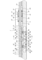
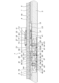
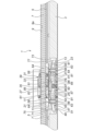
以下、図1乃至図10を参照しながら、本発明の第1の実施の形態について説明する。図1はこの第1の実施の形態によるアクチュエータ1の全体構成を示す斜視図であり、図2は要部縦断面図、図3は図2のIII-III断面図である。図1~図3に示すように、略U字型の断面形状を成すベース3がある。上記ベース3の左右両内側面にはガイドレール5、5が設置されている。上記ガイドレール5、5にはガイド溝7、7がそれぞれ形成されている。 The first embodiment of the present invention will be described below with reference to Figs. 1 to 10. Fig. 1 is a perspective view showing the overall configuration of an actuator 1 according to this first embodiment, Fig. 2 is a longitudinal cross-sectional view of the main parts, and Fig. 3 is a cross-sectional view taken along III-III in Fig. 2. As shown in Figs. 1 to 3, there is a base 3 having a substantially U-shaped cross-section. Guide rails 5, 5 are provided on both the left and right inner surfaces of the base 3. Guide grooves 7, 7 are formed in the guide rails 5, 5, respectively.

また、上記ベース3内にはボールねじ軸9が内装されている。また、図1に示すように、上記ベース3の前端側(図1中左下側)には軸受部8aがあり、上記ベース3の後端側(図2中右上側)には軸受部8bがある。上記ボールねじ軸9はこれら軸受け部8a、8bによって軸支されている。上記ボールねじ軸9には螺旋溝9aが形成されている。 A ball screw shaft 9 is mounted inside the base 3. As shown in FIG. 1, the base 3 has a bearing 8a at its front end (lower left in FIG. 1) and a bearing 8b at its rear end (upper right in FIG. 2). The ball screw shaft 9 is supported by the bearings 8a and 8b. The ball screw shaft 9 has a spiral groove 9a formed in it.

図1、図2に示すように、上記ベース3にはスライダ11が左右方向に移動可能に設置されている。上記スライダ11の幅方向の一方側(図1中左上側)であって前後方向(図1中左下から右上に向かう方向)両端にはそれぞれエンドキャップ13、13が設置されている。また、上記スライダ11の幅方向の他方側(図1中右下側)であって前後方向(図1中左下から右上に向かう方向)両端にはそれぞれエンドキャップ15、15が設置されている(後端側のエンドキャップは図示せず。)。上記エンドキャップ13、15内には図示しないリターン路が形成されている。上記スライダ11内の幅方向(図1中左上から右下に向かう方向)両側にはそれぞれ図示しない無負荷循環路が形成されている。また、上記スライダ11の幅方向(図1中左上から右下に向かう方向)両側面には図示しないガイド溝が形成されている。 1 and 2, the slider 11 is installed on the base 3 so as to be movable in the left-right direction. End caps 13, 13 are installed on one side of the width direction of the slider 11 (upper left side in FIG. 1) at both ends in the front-rear direction (direction from lower left to upper right in FIG. 1). End caps 15, 15 are installed on the other side of the width direction of the slider 11 (lower right side in FIG. 1) at both ends in the front-rear direction (direction from lower left to upper right in FIG. 1) (the end cap on the rear end side is not shown). A return path (not shown) is formed in the end caps 13, 15. Unloaded circulation paths (not shown) are formed on both sides of the width direction of the slider 11 (direction from upper left to lower right in FIG. 1). Also, guide grooves (not shown) are formed on both sides of the width direction of the slider 11 (direction from upper left to lower right in FIG. 1).

上記スライダ11内の図示しない一方の無負荷循環路と、上記一方のエンドキャップ13のリターン路、上記他方のエンドキャップ13のリターン路、及び、上記一方のガイドレール5のガイド溝7と上記スライダ11の図示しない一方のガイド溝の間の空間には、図示しない鋼球が転動・循環されている。また、上記スライダ11内の図示しない他方の無負荷循環路と、上記一方のエンドキャップ15のリターン路、上記他方のエンドキャップ15のリターン路、及び、上記他方のガイドレール5のガイド溝7と上記スライダ11の図示しない他方のガイド溝の間の空間にも、図示しない鋼球が転動・循環されている。このような構成により、上記スライダ11は上記ベース3に対して移動可能となっている。 Steel balls (not shown) roll and circulate in one unloaded circulation path (not shown) in the slider 11, the return path of the one end cap 13, the return path of the other end cap 13, and the space between the guide groove 7 of the one guide rail 5 and one guide groove (not shown) of the slider 11. Steel balls (not shown) roll and circulate in the other unloaded circulation path (not shown) in the slider 11, the return path of the one end cap 15, the return path of the other end cap 15, and the space between the guide groove 7 of the other guide rail 5 and the other guide groove (not shown) of the slider 11. With this configuration, the slider 11 is movable relative to the base 3.

また、図2に示すように、上記スライダ11には、ボールねじナット収容部材27があり、このボールねじナット収容部材27内にはボールねじナット31が固着されている。上記ボールねじナット31にはボールねじナット本体33と、前端側(図2中左側)のエンドキャップ35と、後端側(図2中右側)のエンドキャップ37がある。上記ボールねじ軸9は上記ボールねじナット31を貫通している。上記ボールねじナット本体33の内周面には螺旋溝39が形成されている。また、上記ボールねじナット本体33内には図示しない無負荷循環路が形成されていて、上記エンドキャップ35、37内には図示しないリターン路が形成されている。 As shown in FIG. 2, the slider 11 has a ball screw nut housing member 27, and a ball screw nut 31 is fixed inside the ball screw nut housing member 27. The ball screw nut 31 has a ball screw nut body 33, an end cap 35 on the front end side (left side in FIG. 2), and an end cap 37 on the rear end side (right side in FIG. 2). The ball screw shaft 9 passes through the ball screw nut 31. A spiral groove 39 is formed on the inner peripheral surface of the ball screw nut body 33. An unloaded circulation path (not shown) is formed inside the ball screw nut body 33, and a return path (not shown) is formed inside the end caps 35 and 37.

上記ボールねじナット本体33の図示しない無負荷循環路内、上記エンドキャップ35、37の図示しないリターン路、及び、上記ボールねじナット本体33の螺旋溝39と上記ボールねじ軸9の螺旋溝9aの間の空間には鋼球41が転動・循環されている。また、図1に示すように、上記ベース3の後端側(図1中右上側)にはモータ43が設置されている。このモータ43によって、上記ボールねじ軸9が回転・駆動される。上記ボールねじ軸9が回転・駆動されると、上記スライダ11が前後方向(図2中左右方向)に移動される。 Steel balls 41 roll and circulate in the unloaded circulation path (not shown) of the ball screw nut body 33, the return path (not shown) of the end caps 35 and 37, and the space between the spiral groove 39 of the ball screw nut body 33 and the spiral groove 9a of the ball screw shaft 9. As shown in FIG. 1, a motor 43 is installed on the rear end side of the base 3 (upper right side in FIG. 1). The motor 43 rotates and drives the ball screw shaft 9. When the ball screw shaft 9 rotates and drives, the slider 11 moves in the front-rear direction (left-right direction in FIG. 2).

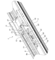
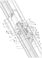
また、図2に示すように、上記スライダ11の下側の前端側(図2中左側)の幅方向両側(図2中紙面方向両側)にはボールねじナット側ローラとして樹脂製の前方ローラ21、21が回転可能に設置されている(図2中手前側の前方ローラ21は図示せず。)。また、上記スライダ11の下側の後端側(図2中右側)の幅方向両側(図2中紙面方向両側)にはボールねじナット側ローラとして樹脂製の後方ローラ23、23が回転可能に設置されている(図2中手前側の後方ローラ23は図示せず。)。また、上記スライダ11の下側の幅方向両端側(図2中紙面方向両側)には、板状の下面側摺動部材25、25が設置されている(図2中手前側の下面側摺動部材25は図示せず。)。 As shown in FIG. 2, resin front rollers 21, 21 are rotatably installed as ball screw nut side rollers on both sides in the width direction (both sides in the paper direction in FIG. 2) of the lower front end side (left side in FIG. 2) of the slider 11 (the front roller 21 on the front side in FIG. 2 is not shown). Resin rear rollers 23, 23 are rotatably installed as ball screw nut side rollers on both sides in the width direction (both sides in the paper direction in FIG. 2) of the lower rear end side (right side in FIG. 2) of the slider 11 (the rear roller 23 on the front side in FIG. 2 is not shown). Plate-shaped lower surface side sliding members 25, 25 are installed on both sides in the width direction (both sides in the paper direction in FIG. 2) of the lower side of the slider 11 (the lower surface side sliding member 25 on the front side in FIG. 2 is not shown).

また、例えば、図2、図4に示すように、上記ベース3にはサポート部材収容凹部51が形成されている。このサポート部材収容凹部51内には、ボールねじ軸サポート構造47が設置されている。上記ボールねじ軸サポート構造47には、まず、サポート部材支持部材50がある。このサポート部材支持部材50にはサポート部材用ベース53がある。上記サポート部材用ベース53の前後両端側にはサポート部材用ベース取付板54、54が固着されている。上記サポート部材用ベース取付板54の両端には貫通孔52、52が形成されている。上記サポート部材用ベース取付板54、54は固定用ねじ58によって上記サポート部材用ベース53に固定されている。上記サポート部材支持部材50にはサポート部材ガイド用支柱55、55がある。上記サポート部材ガイド用支柱55、55は、上記サポート部材用ベース53の前後方向(図2中左右方向)両端に立設されている。上記ガイド用支柱55、55は固定用ねじ56、56によって上記サポート部材用ベース53に固定されている。
上記サポート部材収容凹部51の底部には、図2に示すように、サポート部材用ベース収容孔49が形成されていて、上記サポート部材用ベース53は上記サポート部材用ベース収容孔49内に設置されている。
固定用ねじ59を上記サポート部材用ベース取付板54の貫通孔52に貫通させて上記ベース3に螺合させることで、上記サポート部材用ベース53、ひいては、上記サポート部材支持部材50が上記ベース3に固定されている。
また、上記サポート部材支持部材50には弾性手段としてのコイルバネ65がある。上記コイルバネ65は、後述するサポート部材61と上記サポート部材用ベース53との間に張置されている。
また、上記サポート部材用ベース53の前後方向(図2中左右方向)中央には後述する緩衝機構の一部であるU字型の板バネ57が設置されている。
2 and 4, the base 3 is formed with a support member accommodating recess 51. The ball screw shaft support structure 47 is installed in the support member accommodating recess 51. The ball screw shaft support structure 47 includes a support member support member 50. The support member support member 50 includes a support member base 53. Support member base mounting plates 54, 54 are fixed to both front and rear ends of the support member base 53. Through holes 52, 52 are formed at both ends of the support member base mounting plate 54. The support member base mounting plates 54, 54 are fixed to the support member base 53 by fixing screws 58. The support member support member 50 includes support member guide pillars 55, 55. The support member guide pillars 55, 55 are erected at both ends of the support member base 53 in the front-rear direction (left-right direction in FIG. 2). The guide posts 55, 55 are fixed to the support member base 53 by fixing screws 56, 56.
As shown in FIG. 2, a support member base accommodating hole 49 is formed in the bottom of the support member accommodating recess 51, and the support member base 53 is placed in the support member base accommodating hole 49.
The support member base 53 and, ultimately, the support member support member 50 are fixed to the base 3 by passing a fixing screw 59 through the through hole 52 of the support member base mounting plate 54 and screwing it into the base 3.
Further, the support member supporting member 50 has a coil spring 65 as an elastic means. The coil spring 65 is stretched between a support member 61 (to be described later) and the support member base 53.
A U-shaped leaf spring 57 which is part of a shock-absorbing mechanism (described later) is provided at the center of the support member base 53 in the front-rear direction (left-right direction in FIG. 2).

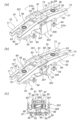
上記ボールねじ軸サポート構造47にはサポート部材61がある。上記サポート部材61は、上記サポート部材収容凹部51内であって上記サポート部材用ベース53の上側に設置されている。図5に示すように、上記サポート部材61にサポート部材本体62があり、上記サポート部材本体62の前後方向(図5中左下から右上に向かう方向)両端側には、ガイド用貫通孔63、63が形成されている。上記ガイド用貫通孔63、63には滑り軸受64、64が圧入されていて、上記サポート部材ガイド用支柱55、55はこれら滑り軸受64、64を貫通するように配置され、上記滑り軸受64、64と摺接するようになっている。上記サポート部材61は上記サポート部材ガイド用支柱55、55に沿って上下方向に移動可能になっている。また、図2に示すように、上記サポート部材61と上記サポート部材用ベース53の間には、前記した弾性手段としてのコイルバネ65が張設されている。上記コイルバネ65により上記サポート部材61は上記ボールねじ軸9側(図2中上側)に常時押圧・付勢されている。
上記のように、上記サポート部材支持部材50は上記サポート部材用ベース53と上記サポート部材用ベース53に固着される上記サポート部材用ベース取付板54、54と上記サポート部材ガイド用支柱55、55と上記サポート部材本体62を弾性支持しているコイルバネ65により構成されている。
The ball screw shaft support structure 47 includes a support member 61. The support member 61 is installed in the support member accommodating recess 51 and above the support member base 53. As shown in FIG. 5, the support member 61 includes a support member body 62, and guide through holes 63, 63 are formed on both ends of the support member body 62 in the front-rear direction (the direction from the lower left to the upper right in FIG. 5). Slide bearings 64, 64 are press-fitted into the guide through holes 63, 63, and the support member guide pillars 55, 55 are arranged to penetrate these slide bearings 64, 64 and are in sliding contact with the slide bearings 64, 64. The support member 61 is movable in the up-down direction along the support member guide pillars 55, 55. In addition, as shown in FIG. 2, a coil spring 65 is stretched between the support member 61 and the support member base 53 as the elastic means. The support member 61 is constantly pressed and urged toward the ball screw shaft 9 (upper side in FIG. 2) by the coil spring 65 .
As described above, the support member support member 50 is composed of the support member base 53, the support member base mounting plates 54, 54 fixed to the support member base 53, the support member guide pillars 55, 55, and a coil spring 65 that elastically supports the support member main body 62.

上記サポート部材本体62の上面側の前方(図5中左下)の幅方向(図5中左上から右下に向かう方向)両側にはサポート部材側傾斜面としての前方側傾斜面71、71が形成されていて、上記サポート部材本体62の上面側の後方(図5中右上)の幅方向(図5中左上から右下に向かう方向)両側にはサポート部材側傾斜面としての後方側傾斜面73、73が形成されている。上記サポート部材61には、サポート部材側傾斜面用緩衝材として、例えば、低反発のゴム製の前方側緩衝材75、75と後方側緩衝材77、77がある。上記前方側緩衝材75、75は上記前方側傾斜面71、71に設置されていて、上記後方側緩衝材77、77は上記後方側傾斜面73、73に設置されている。 Front inclined surfaces 71, 71 are formed on both sides of the front (lower left in FIG. 5) of the upper surface of the support member main body 62 in the width direction (direction from upper left to lower right in FIG. 5) as support member side inclined surfaces, and rear inclined surfaces 73, 73 are formed on both sides of the rear (upper right in FIG. 5) of the upper surface of the support member main body 62 in the width direction (direction from upper left to lower right in FIG. 5) as support member side inclined surfaces. The support member 61 has, for example, front side cushioning materials 75, 75 and rear side cushioning materials 77, 77 made of low-resilience rubber as cushioning materials for the support member side inclined surfaces. The front side cushioning materials 75, 75 are installed on the front side inclined surfaces 71, 71, and the rear side cushioning materials 77, 77 are installed on the rear side inclined surfaces 73, 73.

図2に示すように、上記スライダ11が上記サポート部材61側へ移動して、上記前方ローラ21、21が上記後方側傾斜面73、73の後方側緩衝材77、77に転動していくと、上記サポート部材61が上記コイルバネ65の弾性力に抗して図6中下側に押圧・付勢される。また、上記スライダ11が図2に示す方向とは反対側から上記サポート部材61側へ移動して、後方ローラ23、23が上記前方側傾斜面71、71の前方側緩衝材75、75に転動していく場合も、上記サポート部材61が上記コイルバネ65の弾性力に抗して図6中下側に押圧され付勢される。 2, when the slider 11 moves toward the support member 61 and the front rollers 21, 21 roll against the rear cushioning materials 77, 77 of the rear inclined surfaces 73, 73, the support member 61 is pressed and urged downward in FIG. 6 against the elastic force of the coil spring 65. Also, when the slider 11 moves toward the support member 61 from the opposite side to the direction shown in FIG. 2 and the rear rollers 23, 23 roll against the front cushioning materials 75, 75 of the front inclined surfaces 71, 71, the support member 61 is pressed and urged downward in FIG. 6 against the elastic force of the coil spring 65.

また、上記サポート部材61にはサポート部81がある。上記サポート部材本体62の上面側の中央にはサポート部用凹部79が形成されていて、上記サポート部81はこのサポート部用凹部79に設置されている。上記サポート部81には、例えば、POM(ポリオキシメチレン)製の受け部材83と、例えば、フェルト製の受け部材用緩衝材87がある。上記受け部材83は上面側に配置されていて上記ボールねじ軸9を受けるようになっている。上記受け部材83は上記受け部材用緩衝材87を介して上記サポート部用凹部79内に着脱可能に設置されている。
上記受け部材83には座グリ付きの貫通孔88、88が形成されていて、上記受け部材83はボルト89、89を上記貫通孔88、88に貫通させて上記サポート部用凹部79に形成された雌ねじ部67、67に螺合させることで上記サポート部材本体62に固定されている。上記受け部材用緩衝材87は上記ボルト89、89により、上記受け部材83と共締め固定されている。また、上記サポート部用凹部79に形成された雌ねじ部67、67の上記サポート部材本体62の下面側からセットスクリュー84、84を螺合させており、上記セットスクリュー84、84の螺合位置を調整することで、上記受け部材用緩衝材87の必要以上のつぶれを防止するとともに、上記受け部材83の高さを調整している。
上記受け部材83の上面側には上記ボールねじ軸9を受けるための凹部85が形成されている。上記受け部材83の上記凹部85の幅方向両側(図5中)は平面状の摺動部86、86となっている。図2に示すように、上記サポート部材61が上記コイルバネ65の弾性力により図2中上側に押圧・付勢されると、上記サポート部81の受け部材83の凹部85によって上記ボールねじ軸9の中央付近が支持されて、上記ボールねじ軸9の撓みが防止される。
また、上記受け部材83の前方には上記サポート部材本体62の前方側傾斜面71、71と略連続する前方側傾斜面82aが形成されていて、上記受け部材83の後方には上記サポート部材本体62の後方側傾斜面73、73と略連続する後方側傾斜面82bが形成されている。
The support member 61 also has a support portion 81. A support portion recess 79 is formed in the center of the upper surface side of the support member main body 62, and the support portion 81 is installed in this support portion recess 79. The support portion 81 has a receiving member 83 made of, for example, POM (polyoxymethylene) and a receiving member cushioning material 87 made of, for example, felt. The receiving member 83 is disposed on the upper surface side and is adapted to receive the ball screw shaft 9. The receiving member 83 is detachably installed in the support portion recess 79 via the receiving member cushioning material 87.
The receiving member 83 has through holes 88, 88 with countersunk holes, and the receiving member 83 is fixed to the support member main body 62 by passing bolts 89, 89 through the through holes 88, 88 and screwing them into the female threaded portions 67, 67 formed in the support portion recess 79. The receiving member cushioning material 87 is fastened and fixed together with the receiving member 83 by the bolts 89, 89. In addition, set screws 84, 84 are screwed into the female threaded portions 67, 67 formed in the support portion recess 79 from the lower surface side of the support member main body 62, and by adjusting the screwing positions of the set screws 84, 84, the receiving member cushioning material 87 is prevented from being crushed more than necessary and the height of the receiving member 83 is adjusted.
A recess 85 for receiving the ball screw shaft 9 is formed on the upper surface side of the receiving member 83. Both sides in the width direction (in FIG. 5) of the recess 85 of the receiving member 83 are planar sliding portions 86, 86. As shown in FIG. 2, when the support member 61 is pressed and urged upward in FIG. 2 by the elastic force of the coil spring 65, the recess 85 of the receiving member 83 of the support portion 81 supports the vicinity of the center of the ball screw shaft 9, preventing the ball screw shaft 9 from bending.
In addition, a front side inclined surface 82a that is approximately continuous with the front side inclined surfaces 71, 71 of the support member main body 62 is formed in front of the receiving member 83, and a rear side inclined surface 82b that is approximately continuous with the rear side inclined surfaces 73, 73 of the support member main body 62 is formed behind the receiving member 83.

上記フェルト製の受け部材用緩衝材87は上記受け部材83の上記ボールねじ軸9への衝突時の衝撃を緩和させるためのものであり、また、上記サポート部材本体62の下面側にも、例えば、低反発のゴム製のサポート部材用緩衝材91、91が設置されている。これらサポート部材用緩衝材91、91によって、上記サポート部材61が上記サポート部材用ベース53に衝突する際の衝撃を緩和する。
上記のように、上記サポート部材61は上記サポート部材本体62と上記サポート部材本体62に設置される上記サポート部81と上記サポート部材本体62の上記前方側傾斜面71、71および上記後方側傾斜面73、73に設置される上記前方側緩衝材75、75と上記後方側緩衝材77、77により構成されている。
The felt cushioning material 87 for receiving member is intended to reduce the impact when the receiving member 83 collides with the ball screw shaft 9, and also, for example, cushioning materials 91, 91 for supporting member made of low-resilience rubber are provided on the lower surface side of the support member main body 62. These cushioning materials 91, 91 for supporting member reduce the impact when the support member 61 collides with the support member base 53.
As described above, the support member 61 is composed of the support member main body 62, the support portion 81 installed on the support member main body 62, and the front side cushioning materials 75, 75 and rear side cushioning materials 77, 77 installed on the front side inclined surfaces 71, 71 and the rear side inclined surfaces 73, 73 of the support member main body 62.

また、図2に示すように、上記サポート部材用ベース53の前後方向(図2中左右方向)中央には後述する緩衝機構の一部であるU字型の板バネ57が設置され、固定用ねじ96、96によって上記サポート部材用ベース53に固定されている。また、図3、図5に示すように、上記サポート部材61の幅方向(図3中左右方向)両側には、後述する緩衝機構の一部である当接部材93、93が固着されている。上記サポート部材61は上記当接部材93、93を介して上記板バネ57の両端の間に介挿されている。上記板バネ57と上記当接部材93、93によって緩衝機構95が構成されている。上記緩衝機構95によって上記サポート部材61の上方向の移動、すなわち、上記ボールねじ軸9に接近する動作が緩衝される。 As shown in FIG. 2, a U-shaped leaf spring 57, which is part of a cushioning mechanism described later, is installed in the center of the support member base 53 in the front-rear direction (left-right direction in FIG. 2), and is fixed to the support member base 53 by fixing screws 96, 96. As shown in FIG. 3 and FIG. 5, abutment members 93, 93, which are part of a cushioning mechanism described later, are fixed to both sides of the support member 61 in the width direction (left-right direction in FIG. 3). The support member 61 is inserted between both ends of the leaf spring 57 via the abutment members 93, 93. The leaf spring 57 and the abutment members 93, 93 form a cushioning mechanism 95. The cushioning mechanism 95 cushions the upward movement of the support member 61, i.e., the movement of the support member 61 toward the ball screw shaft 9.

次に、この第1の実施の形態による作用について説明する。モータ43によってボールねじ軸9が回転・駆動されると、スライダ11が前後方向に進退される。上記スライダ11がサポート部材61と離間している状態では、図2に示すように、上記サポート部材61はコイルバネ65の弾性力により図2中上側に押圧・付勢されていて、サポート部81の受け部材83の凹部85によって上記ボールねじ軸9の中央付近が支持されて、上記ボールねじ軸9の撓みが防止されている。 Next, the operation of this first embodiment will be described. When the ball screw shaft 9 is rotated and driven by the motor 43, the slider 11 advances and retreats in the front-rear direction. When the slider 11 is separated from the support member 61, as shown in FIG. 2, the support member 61 is pressed and urged upward in FIG. 2 by the elastic force of the coil spring 65, and the center of the ball screw shaft 9 is supported by the recess 85 of the receiving member 83 of the support portion 81, preventing the ball screw shaft 9 from bending.

図6、図7に示すように、上記スライダ11が図6中右側から上記サポート部材61に接近すると、前方ローラ21、21が上記後方側傾斜面73、73の後方側緩衝材77、77に当接して転動し始める。それによって、上記サポート部材61は上記コイルバネ65の弾性力に抗して反ボールねじ軸9側(図6中下側)に押圧・付勢され、上記受け部材83の凹部85による上記ボールねじ軸9の支持は解除される。上記前方ローラ21、21が上記後方側緩衝材77、77に衝突する際の衝撃は上記後方側緩衝材77、77によって緩和される。図8は上記スライダ11がさらに上記サポート部材61側に接近した状態を示しており、上記サポート部材61が反ボールねじ軸9側(図8中下側)にさらに押圧・付勢されている。
上記スライダ11が更に図8中左側に移動すると、上記前方ローラ21、21は上記受け部材83の後方側傾斜面82b、82bに当接して転動し、その後上記受け部材83の摺動部86、86に当接して転動し、更に上記受け部材83の前方側傾斜面82a、82aに当接して転動する。
As shown in Figures 6 and 7, when the slider 11 approaches the support member 61 from the right side in Figure 6, the front rollers 21, 21 come into contact with the rear buffer materials 77, 77 of the rear inclined surfaces 73, 73 and start rolling. As a result, the support member 61 is pressed and urged toward the side opposite to the ball screw shaft 9 (lower side in Figure 6) against the elastic force of the coil spring 65, and the support of the ball screw shaft 9 by the recess 85 of the receiving member 83 is released. The impact when the front rollers 21, 21 collide with the rear buffer materials 77, 77 is mitigated by the rear buffer materials 77, 77. Figure 8 shows a state in which the slider 11 approaches further toward the support member 61, and the support member 61 is further pressed and urged toward the side opposite to the ball screw shaft 9 (lower side in Figure 8).
When the slider 11 moves further to the left in Figure 8, the front rollers 21, 21 abut against the rear inclined surfaces 82b, 82b of the receiving member 83 and roll, then abut against the sliding portions 86, 86 of the receiving member 83 and roll, and further abut against the front inclined surfaces 82a, 82a of the receiving member 83 and roll.

図9に示すように、上記スライダ11が上記サポート部材61の真上に移動すると、上記前方ローラ21、21は上記受け部材83から離れるが、上記サポート部材61の受け部材83の摺動部86、86が、上記スライダ11の下面側摺動部材25、25に摺接される。このとき、上記サポート部材61は最も下側に押圧・付勢されている。上記サポート部材61が上記サポート部材用ベース53に衝突する際の衝撃はサポート部材用緩衝材91、91によって緩和される。 As shown in FIG. 9, when the slider 11 moves directly above the support member 61, the front rollers 21, 21 move away from the receiving member 83, but the sliding parts 86, 86 of the receiving member 83 of the support member 61 slide against the lower side sliding members 25, 25 of the slider 11. At this time, the support member 61 is pressed and urged to the lowest side. The impact when the support member 61 collides with the support member base 53 is mitigated by the support member cushioning materials 91, 91.

次に、上記スライダ11が上記サポート部材61の上側を通過していくと、上記スライダ11の後方ローラ23、23が、上記受け部材83の後方側傾斜面82b、82b、摺動部86、86、及び、前方側傾斜面82a、82aに当接して転動された後、前方側傾斜面71、71の前方側緩衝材75、75を介して上記サポート部材61を上記コイルバネ65の弾性力に抗して反ボールねじ軸9側(図10中下側)に押圧・付勢した状態になるが、上記スライダ11の移動によりその押圧・付勢は徐々に解除されていく。そして、図10に示すように、上記スライダ11が図10中左側に移動されると、再び上記サポート部材61はコイルバネ65の弾性力により図10中上側に押圧・付勢され、サポート部81の受け部材83の凹部85によって上記ボールねじ軸9の中央付近が支持されて、上記ボールねじ軸9の撓みが防止される状態となる。上記受け部材83が上記ボールねじ軸9に再び当接される際の衝撃は受け部材用緩衝材87によって緩衝される。
また、上記サポート部材61が上側に復帰する際の急激な上昇は緩衝機構95の上記板バネ57と上記当接部材93とが接触し抵抗となることによって緩和され、それによって騒音の発生を防止している。
Next, as the slider 11 passes above the support member 61, the rear rollers 23, 23 of the slider 11 roll against the rear inclined surfaces 82b, 82b, sliding portions 86, 86, and front inclined surfaces 82a, 82a of the receiving member 83, and then press and urge the support member 61 toward the anti-ball screw shaft 9 side (lower side in Figure 10) against the elastic force of the coil spring 65 via the front cushioning materials 75, 75 of the front inclined surfaces 71, 71. However, as the slider 11 moves, this pressing and urging is gradually released. 10, when the slider 11 is moved to the left in Fig. 10, the support member 61 is again pressed and urged upward in Fig. 10 by the elastic force of the coil spring 65, and the vicinity of the center of the ball screw shaft 9 is supported by the recess 85 of the receiving member 83 of the support portion 81, thereby preventing the ball screw shaft 9 from bending. The impact when the receiving member 83 comes into contact with the ball screw shaft 9 again is buffered by the receiving member buffer material 87.
Furthermore, the sudden rise of the support member 61 when it returns to the upper side is mitigated by the leaf spring 57 of the buffer mechanism 95 coming into contact with the abutment member 93 and providing resistance, thereby preventing the generation of noise.

また、スライダ11が図2に示す方向とは反対側からサポート部材61に接近して通過していく場合も同様である。この場合には、スライダ11の後方ローラ23、23がサポート部材61の前方側傾斜面71、71の前方側緩衝材75、75に当接して転動していくことによりサポート部材61がコイルバネ65の付勢力に抗して押し下げられることになる。
また、上記ボールねじ軸サポート構造47は1つのユニットとして上記サポート部材収容凹部51に着脱できる構造となっている。
The same applies to the case where the slider 11 approaches and passes over the support member 61 from the opposite direction to the direction shown in Fig. 2. In this case, the rear rollers 23, 23 of the slider 11 abut against the front cushioning materials 75, 75 of the front inclined surfaces 71, 71 of the support member 61 and roll, so that the support member 61 is pressed down against the biasing force of the coil spring 65.
Moreover, the ball screw shaft support structure 47 is structured so as to be detachable from the support member accommodating recess 51 as a single unit.

次に、この第1の実施の形態による効果について説明する。
まず、簡易且つコンパクトな構成によりボールねじ軸9の撓みを防止することができ、振動や騒音を抑制して高速化に対応することができる。すなわち、ボールねじ軸9を支持する受け部材83を備えたサポート部材61をコイルバネ65によって常時ボールねじ軸9側に付勢する構成とし、それをスライダ11の前方ローラ21、21及び後方ローラ23、23、上記サポート部材61の前方側傾斜面71、71と後方側傾斜面73、73の協働によって適宜押し下げるように構成したからである。
また、上記受け部材83とサポート部材本体62との間には受け部材用緩衝材87が介挿されているので、上記受け部材83が上記ボールねじ軸9に衝突した際の衝撃を簡易な構成により緩和することができる。
また、上記受け部材83は着脱可能に設置されているので、交換が容易である。
また、上記受け部材用緩衝材87はフェルト製であるので構成は簡単でありその緩衝効果及び吸音効果も高い。
また、上記サポート部材61の下面側にも、サポート部材用緩衝材91、91が設置されているので、上記サポート部材61が上記サポート部材用ベース53に衝突する際の衝撃を緩和することができる。
また、前方ローラ21、後方ローラ23、上記前方側傾斜面71、71、後方側傾斜面73、73の協働によって上記サポート部材61を昇降させるようにしているので、サポート部材61の昇降動作を円滑なものとすることができる。
また、上記前方側傾斜面71、71と後方側傾斜面73、73には、前方側緩衝材75、75と後方側緩衝材77、77が設置されているので、前方ローラ21や後方ローラ23が衝突した際の衝撃を緩和することができる。
上記サポート部材用緩衝材91、91、上記前方側緩衝材75、75、及び、後方側緩衝材77、77は、例えば低反発のゴム製であるので、簡単な構成で高い緩衝効果を得ることができる。
また、緩衝機構95が設けられているので、上記サポート部材61の急激な上昇を抑え、上記ボールねじ軸9への衝撃を緩和するとともに騒音を防止することができる。また、上記緩衝機構95は上記板バネ57と上記当接部材93、93によって構成されているので、その構成も簡単である。
また、アクチュエータ1には一つの上記サポート部材61が設置されているので、その構成も簡単である。
Next, the effects of the first embodiment will be described.
First, the simple and compact configuration can prevent bending of the ball screw shaft 9, suppressing vibration and noise and enabling higher speeds to be accommodated. That is, the support member 61 having the receiving member 83 that supports the ball screw shaft 9 is constantly biased toward the ball screw shaft 9 by the coil spring 65, and is appropriately pressed down by cooperation of the front rollers 21, 21 and rear rollers 23, 23 of the slider 11 and the front inclined surfaces 71, 71 and rear inclined surfaces 73, 73 of the support member 61.
In addition, since a cushioning material 87 for the receiving member is interposed between the receiving member 83 and the support member main body 62, the impact when the receiving member 83 collides with the ball screw shaft 9 can be mitigated with a simple structure.
Moreover, since the receiving member 83 is detachably installed, it can be easily replaced.
Moreover, since the cushioning material 87 for the receiving member is made of felt, the structure is simple and the cushioning effect and sound absorbing effect are high.
In addition, since support member cushioning materials 91, 91 are also provided on the lower surface side of the support member 61, it is possible to reduce the impact when the support member 61 collides with the support member base 53.
In addition, since the support member 61 is raised and lowered by cooperation of the front roller 21, the rear roller 23, the front inclined surfaces 71, 71, and the rear inclined surfaces 73, 73, the raising and lowering operation of the support member 61 can be made smooth.
In addition, front cushioning materials 75, 75 and rear cushioning materials 77, 77 are provided on the front inclined surfaces 71, 71 and rear inclined surfaces 73, 73, so that the impact when the front roller 21 or the rear roller 23 collides can be mitigated.
The support member cushioning materials 91, 91, the front side cushioning materials 75, 75 and the rear side cushioning materials 77, 77 are made of, for example, low-resilience rubber, and therefore a high cushioning effect can be obtained with a simple structure.
In addition, since a buffer mechanism 95 is provided, it is possible to suppress a sudden rise of the support member 61, reduce the impact on the ball screw shaft 9, and prevent noise. In addition, since the buffer mechanism 95 is composed of the leaf spring 57 and the abutment members 93, 93, the configuration is also simple.
Furthermore, since the actuator 1 is provided with one support member 61, the structure is simple.

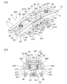
次に、図11を参照しながら、本発明の第2の実施の形態について説明する。
図11に示すように、この第2の実施の形態によるアクチュエータ101には、前記した第1の実施の形態の場合と同様にボールねじ軸サポート構造47が設けられているが、スライダ11の下側には前方ローラ21、21の代わりに前方側傾斜面部材103、103が設けられていて、後方ローラ23、23の代わりに、後方側傾斜面部材105、105が設けられている。
Next, a second embodiment of the present invention will be described with reference to FIG.
As shown in FIG. 11, the actuator 101 according to the second embodiment is provided with a ball screw shaft support structure 47 similar to the first embodiment described above, but front inclined surface members 103, 103 are provided under the slider 11 in place of the front rollers 21, 21, and rear inclined surface members 105, 105 are provided in place of the rear rollers 23, 23.

上記前方側傾斜面部材103は、例えば、図11(b)に示すように、サポート部材本体62の後方側傾斜面73と平行なボールねじナット側傾斜面107が設けられた部材である。また、上記後方側傾斜面部材105は、上記サポート部材本体62の前方側傾斜面71と平行なボールねじナット側傾斜面109が設けられた部材である。 The front side inclined surface member 103 is a member provided with a ball screw nut side inclined surface 107 that is parallel to the rear side inclined surface 73 of the support member main body 62, as shown in FIG. 11(b), for example. The rear side inclined surface member 105 is a member provided with a ball screw nut side inclined surface 109 that is parallel to the front side inclined surface 71 of the support member main body 62.

この第2の実施の形態の場合は、上記前方側傾斜面部材103のボールねじナット側傾斜面107が上記サポート部材本体62の後方側傾斜面73に当接する、または、上記後方側傾斜面部材105のボールねじナット側傾斜面109が上記サポート部材本体62の前方側傾斜面71に当接することで、サポート部材61が下側に押し下げられる。
また、図5に示すように、上記サポート部材本体62の上記前方側傾斜面71と上記後方側傾斜面73には前方側緩衝材75と後方側緩衝材77が設置されているが、上記傾斜面107や上記傾斜面109にも図示しない緩衝材を設置してもよい。
また、上記サポート部材本体62の上記前方側傾斜面71と上記後方側傾斜面73に緩衝材を設置せず、上記傾斜面107や上記傾斜面109に図示しない緩衝材を設置する場合も考えられる。
なお、前記第1の実施の形態の場合と共通する構成には同一符号を付して示しその説明を省略する。
In the case of this second embodiment, the ball screw nut side inclined surface 107 of the front side inclined surface member 103 abuts against the rear side inclined surface 73 of the support member main body 62, or the ball screw nut side inclined surface 109 of the rear side inclined surface member 105 abuts against the front side inclined surface 71 of the support member main body 62, thereby pushing the support member 61 downward.
As shown in FIG. 5, a front cushioning material 75 and a rear cushioning material 77 are provided on the front inclined surface 71 and the rear inclined surface 73 of the support member main body 62, but cushioning materials (not shown) may also be provided on the inclined surface 107 and the inclined surface 109.
Further, it is also possible to consider a case where no cushioning material is provided on the front inclined surface 71 and the rear inclined surface 73 of the support member main body 62, but a cushioning material (not shown) is provided on the inclined surface 107 and the inclined surface 109.
The same components as those in the first embodiment are denoted by the same reference numerals and the description thereof will be omitted.

次に、図12を参照しながら、本発明の第3の実施の形態について説明する。
図12に示すように、アクチュエータ201は、前記した第2の実施の形態の場合と同様に、スライダ11の下側に前方側傾斜面部材103、103と後方側傾斜面部材105、105が設置されているが、ベース3のサポート部材収容凹部51内にはボールねじ軸サポート構造203が設置されている。
Next, a third embodiment of the present invention will be described with reference to FIG.
As shown in Figure 12, the actuator 201 has front side inclined surface members 103, 103 and rear side inclined surface members 105, 105 installed on the underside of the slider 11, as in the case of the second embodiment described above, but a ball screw shaft support structure 203 is installed within the support member accommodating recess 51 of the base 3.

上記ボールねじ軸サポート構造203には、サポート部材204とサポート部材支持部材50がある。上記サポート部材204にはサポート部材本体205がある。上記サポート部材本体205の前後方向(図12(a)中左下から右上に向かう方向)両端には、ガイド用貫通孔207、207が形成されている。上記ガイド用貫通孔207、207には滑り軸受209、209が圧入されていて、サポート部材ガイド用支柱55、55はこれら滑り軸受209、209を貫通するように配置され、上記滑り軸受209、209と摺接するようになっている。 The ball screw shaft support structure 203 includes a support member 204 and a support member support member 50. The support member 204 includes a support member body 205. Guide through holes 207, 207 are formed at both ends of the support member body 205 in the front-rear direction (the direction from the lower left to the upper right in FIG. 12(a)). Slide bearings 209, 209 are pressed into the guide through holes 207, 207, and the support member guide pillars 55, 55 are arranged to pass through these slide bearings 209, 209 and are in sliding contact with the slide bearings 209, 209.

上記サポート部材本体205の幅方向(図12(a)中左上から右下に向かう方向)両端にはサポート部材側ローラ211、211が回転可能に設置されている。この第3の実施の形態の場合は、上記サポート部材側ローラ211、211が上記スライダ11に設置された前方側傾斜面部材103の傾斜面107や後方側傾斜面部材105の傾斜面109に当接して転動されることで、上記サポート部材204が下側に押圧され付勢されるようになっている。
また、上記傾斜面107や上記傾斜面109に図示しない緩衝材を設置する場合も考えられる。
なお、前記第1の実施の形態の場合と共通する構成には同一符号を付して示しその説明を省略する。
Support member side rollers 211, 211 are rotatably installed on both ends in the width direction (the direction from the upper left to the lower right in FIG. 12(a)) of the support member main body 205. In the case of the third embodiment, the support member side rollers 211, 211 abut against the inclined surface 107 of the front side inclined surface member 103 and the inclined surface 109 of the rear side inclined surface member 105 installed on the slider 11 and roll, so that the support member 204 is pressed downward and urged.
Further, a buffer material (not shown) may be provided on the inclined surface 107 and the inclined surface 109 .
The same components as those in the first embodiment are denoted by the same reference numerals and the description thereof will be omitted.

次に、図13を参照しながら、本発明の第4の実施の形態について説明する。
この第4の実施の形態では、図13に示すようなボールねじ軸サポート構造301が用いられている。このボールねじ軸サポート構造301は、前記した第1の実施の形態や第2の実施の形態におけるボールねじ軸サポート構造47と略同様の構成であるが、緩衝機構95の代わりに緩衝機構303が設けられている。
Next, a fourth embodiment of the present invention will be described with reference to FIG.
In the fourth embodiment, a ball screw shaft support structure 301 as shown in Fig. 13 is used. This ball screw shaft support structure 301 has a configuration substantially similar to the ball screw shaft support structure 47 in the first and second embodiments described above, but a buffer mechanism 303 is provided instead of the buffer mechanism 95.

上記緩衝機構303は、サポート部材用ベース53に固定された略U字型の横断面形状を成す当接部材305と、サポート部材本体62の幅方向(図13(c)中左右方向)両側に設置された板バネ307、307とから構成される。
例えば図13(a)に示すようにサポート部材61は上記当接部材305の内側に配置されていて、上記板バネ307、307の先端側は図13(b)や図13(c)に示すように上記当接部材305の内側の側面に当接して付勢している。
The buffer mechanism 303 is composed of a contact member 305 having an approximately U-shaped cross-sectional shape fixed to the support member base 53, and leaf springs 307, 307 installed on both sides of the width direction (left and right direction in Figure 13 (c)) of the support member main body 62.
For example, as shown in FIG. 13(a), the support member 61 is disposed inside the abutment member 305, and the tip sides of the leaf springs 307, 307 abut against the inner side surface of the abutment member 305 to bias it, as shown in FIG. 13(b) and FIG. 13(c).

上記緩衝機構303によると、前記した第1の実施の形態の場合の緩衝機構95と同様、上記サポート部材61の上方向の移動、すなわち、上記ボールねじ軸9に接近する動作が緩衝される。 The buffer mechanism 303, like the buffer mechanism 95 in the first embodiment described above, buffers the upward movement of the support member 61, i.e., the movement toward the ball screw shaft 9.

次に、図14を参照しながら、本発明の第5の実施の形態について説明する。
この第5の実施の形態では、図14に示すようなボールねじ軸サポート構造401が用いられている。このボールねじ軸サポート構造401は、前記した第1の実施の形態や第2の実施の形態におけるボールねじ軸サポート構造47と略同様の構成であるが、サポート部材本体62の幅方向(図14(b)中左右方向)両側に緩衝機構403、403が設けられている。
Next, a fifth embodiment of the present invention will be described with reference to FIG.
In the fifth embodiment, a ball screw shaft support structure 401 as shown in Fig. 14 is used. This ball screw shaft support structure 401 has a configuration substantially similar to the ball screw shaft support structure 47 in the first and second embodiments described above, but buffer mechanisms 403, 403 are provided on both sides in the width direction (left and right direction in Fig. 14(b)) of the support member main body 62.

上記緩衝機構403にはダンパ取付部材405がある。図14(a)にしめすように、ダンパ取付部材405の中央には段付き貫通孔407、407が設けられている。上記ダンパ取付部材405は、固定用ねじ409、409を上記段付き貫通孔407、407に貫通させてサポート部材本体62に螺合させることで、上記サポート部材本体62に固定されている。
また、図14(a)にしめすように、上記ダンパ取付部材405の前後方向両端にはダンパ411、411が設置されている。上記ダンパ411にはシリンダ413とロッド415がある。上記シリンダ413内には図示しないオイルが封入されていて、上記ロッド415の上記シリンダ413内部側の端部には図示しないピストンが固着されている。上記ロッド415の図14中下端は図示しないアクチュエータのベースに固着されている。よって、サポート部材61が図14中上下方向に移動されると、上記シリンダ413が上記ロッド415に対して相対的に移動されることになる。このとき、上記シリンダ413内の図示しないオイルの抵抗により上記シリンダ413、ひいては、上記サポート部材61の移動が緩衝される。
The buffer mechanism 403 has a damper mounting member 405. As shown in Fig. 14(a), stepped through holes 407, 407 are provided in the center of the damper mounting member 405. The damper mounting member 405 is fixed to the support member main body 62 by passing fixing screws 409, 409 through the stepped through holes 407, 407 and screwing them into the support member main body 62.
14(a), dampers 411, 411 are provided at both front and rear ends of the damper mounting member 405. The damper 411 has a cylinder 413 and a rod 415. Oil (not shown) is sealed in the cylinder 413, and a piston (not shown) is fixed to the end of the rod 415 on the inside side of the cylinder 413. The lower end of the rod 415 in FIG. 14 is fixed to the base of an actuator (not shown). Therefore, when the support member 61 is moved in the vertical direction in FIG. 14, the cylinder 413 is moved relative to the rod 415. At this time, the movement of the cylinder 413 and, by extension, the support member 61 is buffered by the resistance of the oil (not shown) in the cylinder 413.

次に、図15を参照しながら、本発明の第6の実施の形態について説明する。
この第6の実施の形態では、図15に示すようなボールねじ軸サポート構造501が用いられている。このボールねじ軸サポート構造501は、前記した第1の実施の形態や第2の実施の形態におけるボールねじ軸サポート構造47と略同様の構成であるが、サポート部材用ベース53に緩衝機構503が設置されている。
上記緩衝機構503には上記サポート部材用ベース53に固着された長方形のプレート505がある。このプレート505の各角部にはダンパ507、507、507、507(図15(a)中左端のダンパ507は図示されていない)が設置されている。上記ダンパ507は前記した第5の実施の形態のダンパ411と同様の構成であり、シリンダ509とロッド511がある。上記シリンダ509は上記プレート505に固着されており、上記ロッド511の図15中上端がサポート部材本体62の底面に固着されている。
上記ダンパ507によってサポート部材61の図15中上下方向の移動が緩衝される。
Next, a sixth embodiment of the present invention will be described with reference to FIG.
In the sixth embodiment, a ball screw shaft support structure 501 as shown in Fig. 15 is used. This ball screw shaft support structure 501 has a configuration substantially similar to the ball screw shaft support structure 47 in the first and second embodiments described above, but a buffer mechanism 503 is provided on a support member base 53.
The buffer mechanism 503 has a rectangular plate 505 fixed to the support member base 53. Dampers 507, 507, 507, 507 (the damper 507 at the left end in FIG. 15(a) is not shown) are provided at each corner of this plate 505. The damper 507 has a similar structure to the damper 411 in the fifth embodiment described above, and has a cylinder 509 and a rod 511. The cylinder 509 is fixed to the plate 505, and the upper end of the rod 511 in FIG. 15 is fixed to the bottom surface of the support member main body 62.
The damper 507 damps the movement of the support member 61 in the vertical direction in FIG.

次に、図16を参照しながら、本発明の第7の実施の形態について説明する。
前記第1の実施の形態の場合は、軸方向の中央一箇所に1個のボールねじ軸サポート構造47が設けられた構成を例に挙げて説明したが、この第7の実施の形態によるアクチュエータ701の場合には、軸方向の二箇所にボールねじ軸サポート構造47、47をそれぞれ設置した構成になっている。
なお、その他の構成は前記第1の実施の形態の場合と同じであり、図中同一部分には同一符号を付して示しその説明を省略する。
Next, a seventh embodiment of the present invention will be described with reference to FIG.
In the first embodiment described above, a configuration was given in which one ball screw shaft support structure 47 was provided at one central location in the axial direction, but in the actuator 701 according to the seventh embodiment, ball screw shaft support structures 47, 47 are provided at two locations in the axial direction.
Other configurations are the same as those in the first embodiment, and the same parts in the drawings are given the same reference numerals and their explanation is omitted.

この第7の実施の形態の場合も前記第1の実施の形態の場合と同様の作用・効果を奏するが、この第7の実施の形態の場合では前記第1の実施の形態の場合よりも長いボールねじ軸9であっても、上記ボールねじ軸9の撓みを防止して振動や騒音を抑制し高速に動作させることができる。 The seventh embodiment has the same action and effect as the first embodiment, but even if the ball screw shaft 9 is longer than in the first embodiment, the seventh embodiment prevents the ball screw shaft 9 from bending, suppresses vibration and noise, and allows high-speed operation.

なお、本発明は前記第1~第7の実施の形態に限定されない。
まず、前記第1~第7の実施の形態の場合にはサポート部材を1個、2個設けた場合を説明したが、それに限定されるものではなく、3個以上設ける場合も考えられる。
また、受け部材の材質は、POMの他に含油焼結材料等摺動性が良好な様々な場合が考えられる。
また、緩衝材の材質は、フェルトや低反発のゴムの他に、その他の布、ゴム、樹脂、ゲル状材料、スポンジ等の多孔質材料等様々な場合が考えられる。
また、ローラの材質は、樹脂の他にゴム、含油焼結材料等様々な場合が考えられる。
また、サポート部材用ベースをアクチュエータのベースと一体とし、サポート部材ガイド用支柱を直接ベースに固着することもできる。
その他、図示した構成はあくまで一例である。
The present invention is not limited to the first to seventh embodiments.
First, in the first to seventh embodiments, the case where one or two support members are provided has been described, but the present invention is not limited to this, and three or more support members may also be provided.
Moreover, the material of the receiving member may be various other materials having good sliding properties, such as oil-impregnated sintered materials, in addition to POM.
The material of the cushioning material may be various, such as felt or low-resilience rubber, other cloth, rubber, resin, gel material, sponge or other porous material.
The roller may be made of various materials such as rubber, oil-impregnated sintered material, etc., in addition to resin.
Also, the support member base can be integrated with the actuator base, and the support member guide posts can be fixed directly to the base.
Additionally, the configurations shown in the drawings are merely examples.

本発明は、ボールねじ軸サポート構造とアクチュエータに係り、特に、簡易且つコンパクトな構成によりボールねじ軸の撓みを防止して振動や騒音を抑制し高速に動作できるように工夫したものに関し、例えば、産業用ロボットに好適である。 The present invention relates to a ball screw shaft support structure and actuator, and in particular to a simple and compact configuration that prevents the ball screw shaft from bending, suppresses vibration and noise, and enables high-speed operation, making it suitable for industrial robots, for example.

1 アクチュエータ
9 ボールねじ軸
11 スライダ
21 前方ローラ
23 後方ローラ
31 ボールねじナット
57 板バネ(緩衝機構の一部)
61 サポート部材
65 コイルバネ(弾性手段)
71 前方側傾斜面
73 後方側傾斜面
81 サポート部
83 受け部材
87 受け部材用緩衝材
95 緩衝機構
101 アクチュエータ
201 アクチュエータ
303 緩衝機構
403 緩衝機構
503 緩衝機構
701 アクチュエータ
REFERENCE SIGNS LIST 1 Actuator 9 Ball screw shaft 11 Slider 21 Front roller 23 Rear roller 31 Ball screw nut 57 Leaf spring (part of the buffer mechanism)
61 Support member 65 Coil spring (elastic means)
71 Front inclined surface 73 Rear inclined surface 81 Support portion 83 Receiving member 87 Cushioning material for receiving member 95 Cushioning mechanism 101 Actuator 201 Actuator 303 Cushioning mechanism 403 Cushioning mechanism 503 Cushioning mechanism 701 Actuator

Claims (8)

ボールねじ軸と、
上記ボールねじ軸に移動可能に螺合されたボールねじナットと、
上記ボールねじ軸に離接可能に設置され弾性手段により上記ボールねじ軸に圧接されているとともに上記ボールねじナットの接近により上記弾性手段の付勢力に抗して上記ボールねじ軸から離間されるサポート部材と、
を具備し、
上記サポート部材はサポート部材本体と、上記ボールねじ軸を受ける受け部材と、から構成され、
上記サポート部材本体には上記ボールねじ軸の軸方向に沿った上記受け部材の両側にサポート部材側傾斜面が設けられていて、
上記サポート部材側傾斜面にはサポート部材側傾斜面用緩衝材が設置されていることを特徴とするボールねじ軸サポート構造。
A ball screw shaft,
a ball screw nut movably screwed to the ball screw shaft;
a support member that is detachably disposed on the ball screw shaft, that is pressed against the ball screw shaft by an elastic means, and that is moved away from the ball screw shaft against the biasing force of the elastic means when the ball screw nut approaches;
Equipped with
The support member is composed of a support member body and a receiving member that receives the ball screw shaft,
The support member body is provided with support member-side inclined surfaces on both sides of the receiving member along the axial direction of the ball screw shaft ,
A ball screw shaft support structure characterized in that a cushioning material for the support member side inclined surface is installed on the support member side inclined surface .
請求項1記載のボールねじ軸サポート構造において、
上記ボールねじナット側にボールねじナット側ローラが設置されていて、上記ボールねじナット側ローラが上記サポート部材側傾斜面に沿って転動することにより上記サポート部材が上記ボールねじ軸に離接することを特徴とするボールねじ軸サポート構造。
2. The ball screw shaft support structure according to claim 1,
a ball screw nut side roller is provided on the ball screw nut side, and the support member moves toward and away from the ball screw shaft by the ball screw nut side roller rolling along the support member side inclined surface .
ボールねじ軸と、
上記ボールねじ軸に移動可能に螺合されたボールねじナットと、
上記ボールねじ軸に離接可能に設置され弾性手段により上記ボールねじ軸に圧接されているとともに上記ボールねじナットの接近により上記弾性手段の付勢力に抗して上記ボールねじ軸から離間されるサポート部材と、
を具備し、
上記サポート部材はサポート部材本体と、上記ボールねじ軸を受ける受け部材と、から構成され、
上記サポート部材本体には上記ボールねじ軸の軸方向に沿った上記受け部材の両側にサポート部材側傾斜面が設けられていて、
上記ボールねじナット側の上記ボールねじ軸の軸方向に沿った両側にボールねじナット側傾斜面が設けられていて、
上記ボールねじナット側傾斜面が上記サポート部材側傾斜面に沿って摺動することにより上記サポート部材が上記ボールねじ軸に離接することを特徴とするボールねじ軸サポート構造。
A ball screw shaft,
a ball screw nut movably screwed to the ball screw shaft;
a support member that is detachably disposed on the ball screw shaft, that is pressed against the ball screw shaft by an elastic means, and that is moved away from the ball screw shaft against the biasing force of the elastic means when the ball screw nut approaches;
Equipped with
The support member is composed of a support member body and a receiving member that receives the ball screw shaft,
The support member body is provided with support member-side inclined surfaces on both sides of the receiving member along the axial direction of the ball screw shaft,
a ball screw nut side inclined surface is provided on both sides along the axial direction of the ball screw shaft on the ball screw nut side ,
a support member that moves in contact with and away from the ball screw shaft by sliding the inclined surface on the ball screw nut side along the inclined surface on the support member side .
請求項記載のボールねじ軸サポート構造において、
上記サポート部材側傾斜面又は上記ボールねじナット側傾斜面の少なくとも一方に傾斜面用緩衝材が設置されていることを特徴とするボールねじ軸サポート構造。
4. The ball screw shaft support structure according to claim 3 ,
A ball screw shaft support structure, characterized in that a cushioning material for an inclined surface is installed on at least one of the inclined surface on the support member side or the inclined surface on the ball screw nut side .
請求項1~請求項の何れかに記載のボールねじ軸サポート構造において、
上記サポート部材本体と上記受け部材との間に受け部材用緩衝材が介挿されることを特徴とするボールねじ軸サポート構造。
In the ball screw shaft support structure according to any one of claims 1 to 4,
A ball screw shaft support structure, characterized in that a cushioning material for the receiving member is interposed between the support member body and the receiving member .
請求項1~請求項5の何れかに記載のボールねじ軸サポート構造において、
上記サポート部材の上記ボールねじ軸に対する接近動作を緩衝する緩衝機構が設けられていることを特徴とするボールねじ軸サポート構造。
In the ball screw shaft support structure according to any one of claims 1 to 5,
a shock absorbing mechanism for absorbing the approaching movement of the support member to the ball screw shaft ,
請求項1~請求項の何れかに記載のボールねじ軸サポート構造のサポート部材が1個設置されていることを特徴とするアクチュエータ An actuator comprising one support member of the ball screw shaft support structure according to any one of claims 1 to 6. 請求項1~請求項6の何れかに記載のボールねじ軸サポート構造のサポート部材が複数個設置されていることを特徴とするアクチュエータ。 7. An actuator comprising a plurality of support members of the ball screw shaft support structure according to claim 1.
JP2023123448A 2019-11-11 2023-07-28 Ball screw shaft support structure and actuator Active JP7621674B2 (en)

Priority Applications (2)

Application Number Priority Date Filing Date Title
JP2023123448A JP7621674B2 (en) 2019-11-11 2023-07-28 Ball screw shaft support structure and actuator
JP2024173148A JP7711999B2 (en) 2019-11-11 2024-10-02 Ball screw shaft support structure and actuator

Applications Claiming Priority (3)

Application Number Priority Date Filing Date Title
JP2019204030A JP7308523B2 (en) 2019-11-11 2019-11-11 Ball screw shaft support structure and actuator
JP2021070507A JP7388732B2 (en) 2019-11-11 2021-04-19 Ball screw shaft support structure and actuator
JP2023123448A JP7621674B2 (en) 2019-11-11 2023-07-28 Ball screw shaft support structure and actuator

Related Parent Applications (1)

Application Number Title Priority Date Filing Date
JP2021070507A Division JP7388732B2 (en) 2019-11-11 2021-04-19 Ball screw shaft support structure and actuator

Related Child Applications (1)

Application Number Title Priority Date Filing Date
JP2024173148A Division JP7711999B2 (en) 2019-11-11 2024-10-02 Ball screw shaft support structure and actuator

Publications (2)

Publication Number Publication Date
JP2023133442A JP2023133442A (en) 2023-09-22
JP7621674B2 true JP7621674B2 (en) 2025-01-27

Family

ID=75899742

Family Applications (4)

Application Number Title Priority Date Filing Date
JP2019204030A Active JP7308523B2 (en) 2019-11-11 2019-11-11 Ball screw shaft support structure and actuator
JP2021070507A Active JP7388732B2 (en) 2019-11-11 2021-04-19 Ball screw shaft support structure and actuator
JP2023123448A Active JP7621674B2 (en) 2019-11-11 2023-07-28 Ball screw shaft support structure and actuator
JP2024173148A Active JP7711999B2 (en) 2019-11-11 2024-10-02 Ball screw shaft support structure and actuator

Family Applications Before (2)

Application Number Title Priority Date Filing Date
JP2019204030A Active JP7308523B2 (en) 2019-11-11 2019-11-11 Ball screw shaft support structure and actuator
JP2021070507A Active JP7388732B2 (en) 2019-11-11 2021-04-19 Ball screw shaft support structure and actuator

Family Applications After (1)

Application Number Title Priority Date Filing Date
JP2024173148A Active JP7711999B2 (en) 2019-11-11 2024-10-02 Ball screw shaft support structure and actuator

Country Status (1)

Country Link
JP (4) JP7308523B2 (en)

Families Citing this family (4)

* Cited by examiner, † Cited by third party
Publication number Priority date Publication date Assignee Title
JP2023030908A (en) * 2021-08-24 2023-03-08 株式会社日立製作所 elevator equipment
JP7635989B2 (en) 2021-08-31 2025-02-26 株式会社アイエイアイ Ball screw shaft support structure and actuator
CN114770188B (en) * 2022-04-22 2024-05-03 北京晶亦精微科技股份有限公司 Transmission support and sliding device
CN115041997B (en) * 2022-07-24 2025-12-19 江西海德汉自动化科技有限公司 Lead screw anti-shake strutting arrangement and contain device's lathe

Citations (1)

* Cited by examiner, † Cited by third party
Publication number Priority date Publication date Assignee Title
JP2017078505A (en) 2015-10-22 2017-04-27 オークマ株式会社 Waste oil recovery device in ball screw support device

Family Cites Families (5)

* Cited by examiner, † Cited by third party
Publication number Priority date Publication date Assignee Title
JPH02150538A (en) * 1988-12-02 1990-06-08 Mitsubishi Heavy Ind Ltd Feed screw device
JPH073936U (en) * 1993-06-04 1995-01-20 亜▲威▼機電股▲分▼有限公司 Anti-vibration stabilizer for long lead screw
US6014906A (en) * 1998-03-31 2000-01-18 Thomson Saginaw Ball Screw Company, Llc Ball screw and nut assembly incorporating a partible multiple jaw support system for supporting an axially rotatable ball screw
JP2002234326A (en) * 2001-02-08 2002-08-20 Kazuo Yamaguchi Vehicle height adjuster for air suspension
DE102016116519A1 (en) * 2016-09-05 2018-03-08 Stabilus Gmbh spring means

Patent Citations (1)

* Cited by examiner, † Cited by third party
Publication number Priority date Publication date Assignee Title
JP2017078505A (en) 2015-10-22 2017-04-27 オークマ株式会社 Waste oil recovery device in ball screw support device

Also Published As

Publication number Publication date
JP7388732B2 (en) 2023-11-29
JP2021119315A (en) 2021-08-12
JP7308523B2 (en) 2023-07-14
JP7711999B2 (en) 2025-07-23
JP2023133442A (en) 2023-09-22
JP2024174181A (en) 2024-12-13
JP2021076195A (en) 2021-05-20

Similar Documents

Publication Publication Date Title
JP7621674B2 (en) Ball screw shaft support structure and actuator
KR101992638B1 (en) Linear actuator having enhanced dustproof structure
CN106044468B (en) The guide device of elevator
JP2000024853A (en) Machine Tools
JP6370006B1 (en) Elevator equipment
JP7606744B2 (en) Ball screw shaft support structure and actuator
JP7635989B2 (en) Ball screw shaft support structure and actuator
JP7539735B2 (en) Ball screw shaft support structure and actuator
JP2024093253A (en) Ball screw shaft support structure and actuator
JP7741551B2 (en) Shock-absorbing slide rail
JP2012146944A (en) Component mounting device
JP5394831B2 (en) Ball screw drive
CN223894891U (en) Multi-point impact-resistant buffer rubber piece
CN212784426U (en) Anti-seismic electric control equipment casing
CN223227702U (en) A linear guide inner slider with buffer protection
JPS63270181A (en) Vibration absorber in printer
CN114658793B (en) Large-stroke anti-tilting synchronous buffering brake device
CN222254746U (en) Bearing assembly support steel frame
JP4449583B2 (en) Machining center and machining center column support method
JP2025077638A (en) Ball screw shaft support structure and actuator
JP2003311580A (en) Raceway protective bellows support for machine tool
CN113056151A (en) Rack system and slide rail mechanism thereof
CN222377092U (en) A shock-absorbing bracket for electromechanical equipment
JP7729953B2 (en) Slide Rail Assembly
CN222277227U (en) Anti-collision linear slide rail

Legal Events

Date Code Title Description
A621 Written request for application examination

Free format text: JAPANESE INTERMEDIATE CODE: A621

Effective date: 20230821

A977 Report on retrieval

Free format text: JAPANESE INTERMEDIATE CODE: A971007

Effective date: 20240724

A131 Notification of reasons for refusal

Free format text: JAPANESE INTERMEDIATE CODE: A131

Effective date: 20240815

A521 Request for written amendment filed

Free format text: JAPANESE INTERMEDIATE CODE: A523

Effective date: 20241002

TRDD Decision of grant or rejection written
A01 Written decision to grant a patent or to grant a registration (utility model)

Free format text: JAPANESE INTERMEDIATE CODE: A01

Effective date: 20241224

A61 First payment of annual fees (during grant procedure)

Free format text: JAPANESE INTERMEDIATE CODE: A61

Effective date: 20250107

R150 Certificate of patent or registration of utility model

Ref document number: 7621674

Country of ref document: JP

Free format text: JAPANESE INTERMEDIATE CODE: R150