JP7621665B2 - device - Google Patents
device Download PDFInfo
- Publication number
- JP7621665B2 JP7621665B2 JP2022141184A JP2022141184A JP7621665B2 JP 7621665 B2 JP7621665 B2 JP 7621665B2 JP 2022141184 A JP2022141184 A JP 2022141184A JP 2022141184 A JP2022141184 A JP 2022141184A JP 7621665 B2 JP7621665 B2 JP 7621665B2
- Authority
- JP
- Japan
- Prior art keywords
- cable
- cover
- case
- mounting
- opening
- Prior art date
- Legal status (The legal status is an assumption and is not a legal conclusion. Google has not performed a legal analysis and makes no representation as to the accuracy of the status listed.)
- Active
Links
- 239000011521 glass Substances 0.000 claims 5
- 238000003780 insertion Methods 0.000 description 29
- 230000037431 insertion Effects 0.000 description 29
- 239000000919 ceramic Substances 0.000 description 17
- 230000002093 peripheral effect Effects 0.000 description 17
- 238000013461 design Methods 0.000 description 8
- 239000000463 material Substances 0.000 description 8
- 239000000853 adhesive Substances 0.000 description 7
- 230000001070 adhesive effect Effects 0.000 description 7
- 229920001971 elastomer Polymers 0.000 description 5
- 238000005452 bending Methods 0.000 description 4
- 238000012986 modification Methods 0.000 description 4
- 230000004048 modification Effects 0.000 description 4
- 239000002184 metal Substances 0.000 description 3
- 238000010586 diagram Methods 0.000 description 2
- 230000000694 effects Effects 0.000 description 2
- 238000000034 method Methods 0.000 description 2
- 241000219122 Cucurbita Species 0.000 description 1
- 235000009852 Cucurbita pepo Nutrition 0.000 description 1
- 230000001133 acceleration Effects 0.000 description 1
- 238000013459 approach Methods 0.000 description 1
- 238000006243 chemical reaction Methods 0.000 description 1
- 238000001514 detection method Methods 0.000 description 1
- 239000000806 elastomer Substances 0.000 description 1
- 230000001771 impaired effect Effects 0.000 description 1
- 238000009434 installation Methods 0.000 description 1
- 230000001105 regulatory effect Effects 0.000 description 1
- 229920005989 resin Polymers 0.000 description 1
- 239000011347 resin Substances 0.000 description 1
- 239000007779 soft material Substances 0.000 description 1
Images


Landscapes
- Fittings On The Vehicle Exterior For Carrying Loads, And Devices For Holding Or Mounting Articles (AREA)
- Time Recorders, Dirve Recorders, Access Control (AREA)
- Insertion, Bundling And Securing Of Wires For Electric Apparatuses (AREA)
Description
本発明は、例えば、機器等に関する。 The present invention relates to, for example, equipment, etc.
筒形状の本体と、その本体の軸方向の一方端部の外周面に回転可能に装着されるリング部と、そのリング部の外側に連結される取付板とを備える取付用ブラケットと、本体の一方端部に取り付けられ、その本体との間でリング部を挟み込んでそのリング部を固定するナット部材とを備えた車載機器が知られている(例えば、特許文献1参照)。 There is known an in-vehicle device that includes a cylindrical main body, a mounting bracket that includes a ring portion rotatably attached to the outer peripheral surface of one axial end of the main body, a mounting plate that is connected to the outside of the ring portion, and a nut member that is attached to one end of the main body and that clamps the ring portion between the main body and the mounting bracket to fix the ring portion (see, for example, Patent Document 1).
例えば、車載機器を車両のフロントガラスの取付位置に取り付けた場合、本体の側面から引き出された電源ケーブルを、例えば上方に引き出し、フロントガラスの上縁部に隣接して設けられるルーフヘッドライニングから車両内部に引き込み、電源に接続することが想定される。その場合、車両内部に引き込まれる部分以外の配線部分は外部に露出してしまい、見栄えが良くなく、いかにも後付けのオプションで取り付けられたものという印象が強くなってしまう可能性があった。そこで、長尺状のカバー部材を配線に沿って取り付け、露出した部分を隠す方法を取り得ることができる。この場合、ルーフヘッドライニングからフロントガラスに沿わせることができる部分については、配線に沿ってカバー部材を取り付ける。しかし、そこから先の部分であって、本体の側面の配線が外部に引き出される位置までの部分については、フロントガラスから浮いてしまって沿わせることができないので、カバー部材を取り付けることができず、配線を隠すことができないという問題点があった。 For example, when an in-vehicle device is attached to a mounting position on the windshield of a vehicle, it is assumed that the power cable drawn from the side of the main body is drawn upward, for example, and then drawn into the interior of the vehicle from the roof headlining provided adjacent to the upper edge of the windshield and connected to a power source. In that case, the wiring other than the part drawn into the interior of the vehicle is exposed to the outside, which may look unattractive and give the strong impression that it was installed as an optional add-on. Therefore, a method can be adopted in which a long cover member is attached along the wiring to hide the exposed part. In this case, the cover member is attached along the wiring for the part that can be aligned from the roof headlining to the windshield. However, for the part beyond that, up to the position where the wiring on the side of the main body is drawn out to the outside, it floats above the windshield and cannot be aligned, so there is a problem that the cover member cannot be attached and the wiring cannot be hidden.
本発明の目的は、例えば、筺体から引き出される配線等を隠すことができる機器等を提供することである。 The object of the present invention is to provide, for example, equipment that can hide wiring that is pulled out from the housing.
(1)機器は、物の取付面の取付位置に取り付けられる筐体を有し、前記筐体の所定面から配線が引き出され、その配線の前記筐体側とは反対側の部分が、前記物の前記取付面に連続して設けられる前記物の部材であって、前記物の内側に隠す為の隠し部材の内側に引き込まれるようにした機器であって、前記配線のうち、前記所定面の位置から前記隠し部材によって隠れる位置までの部分を覆うカバー部材を備える。 (1) The device has a housing that is attached to a mounting position on a mounting surface of an object, wiring is pulled out from a specified surface of the housing, and the portion of the wiring opposite the housing is pulled into a concealing member that is a component of the object that is provided continuously with the mounting surface of the object and that is used to hide the wiring inside the object, and is provided with a cover member that covers the portion of the wiring from the position of the specified surface to the position hidden by the concealing member.
本発明の「機器」は、電子部品を搭載するものであれば何でもよく、例えば、配線を介して外部電源と接続するもの、又は他の機器と電気的に接続することができるものでもよい。機器が取り付けられる対象の「物」は何でもよく、例えば、自動車等の車両、家具、建造物等でもよい。「取付面」とは、筺体が取り付けられる物の一面であって、面形状は何でもよいが、平面であるのが望ましい。また、取付面の角度は限定されず、水平面、垂直面の他に、傾斜面であってもよい。「取付位置」とは、取付面において筐体が取り付けられる位置を意味する。筐体の所定面とは、筺体を構成する面であればどの面でもよいが、取付位置に取り付けられた状態において取付面側に向く面以外の面が望ましい。これにより、取付面が邪魔になることなく、配線を所定面から引き出すことができる。また、「取付面に連続する」とは、例えば、取付面と隣接して連続する、取付面に重なって連続する等の意味であり、取付面に並んで隠し部材の縁(例えば、車両のルーフヘッドライニングの縁に設けられた黒セラライン等)があることを意味する。また、「隠し部材」とは、配線を隠すことができる部材であればよく、その為だけに設けられたものに限定するものではない。また、隠し部材の色は何でもよいが、配線を隠す為には不透明であるのが望ましい。また、配線の「所定面の位置」とは、所定面において配線が引き出される位置であって、筐体の外部に露出する位置を意味する。 The "device" of the present invention may be anything that is equipped with electronic components, for example, something that can be connected to an external power source via wiring, or something that can be electrically connected to other devices. The "object" to which the device is attached may be anything, for example, a vehicle such as an automobile, furniture, a building, etc. The "mounting surface" is one surface of the object to which the housing is attached, and the surface shape may be any, but it is preferably a flat surface. The angle of the mounting surface is not limited, and it may be a horizontal surface, a vertical surface, or an inclined surface. The "mounting position" means the position at which the housing is attached on the mounting surface. The specified surface of the housing may be any surface that constitutes the housing, but it is preferably a surface other than the surface that faces the mounting surface when attached to the mounting position. This allows the wiring to be drawn out from the specified surface without the mounting surface getting in the way. In addition, "continuous with the mounting surface" means, for example, adjacent and continuous with the mounting surface, overlapping and continuous with the mounting surface, etc., and means that there is an edge of a hidden member (for example, a black ceramic line provided on the edge of the roof headlining of a vehicle) next to the mounting surface. Furthermore, the "hiding member" may be any member capable of hiding the wiring, and is not limited to a member provided solely for that purpose. The hiding member may be any color, but it is preferable for it to be opaque in order to hide the wiring. Furthermore, the "position on the specified surface" of the wiring refers to the position on the specified surface where the wiring is pulled out and exposed to the outside of the housing.
機器から引き出された配線は、カバー部材に隠れて外部に露出しないので、機器の筐体と物の隠し部材の間の見栄えを向上できる。さらに、カバー部材は、筺体と隠し部材の間の配線を覆うことから、筺体がカバー部材を介して隠し部材と繋がっているように見えるので、機器と物との間に一体感を持たせることができる。 The wiring drawn out from the device is hidden by the cover member and not exposed to the outside, improving the appearance between the device's housing and the hidden member of the object. Furthermore, since the cover member covers the wiring between the housing and the hidden member, it looks as if the housing is connected to the hidden member via the cover member, creating a sense of unity between the device and the object.
(2)機器は、前記配線を前記所定面から前記取付位置側に引き出し、さらに前記取付面に沿う方向に曲げて方向転換させる方向転換手段を備え、前記カバー部材は、前記配線のうち、前記所定面から前記取付位置側に引き出された所定位置までの部分を覆う第一カバー部材と、前記配線のうち、前記所定位置から前記取付面に沿って引き出され、前記隠し部材によって隠れる位置までの部分を覆う第二カバー部材とを備え、前記第一カバー部材の前記配線を外部に引き出す為の開口部には、前記第二カバー部材の長手方向の一端部の外表面と重なる重複部が設けられるとよい。 (2) The device is provided with a direction changing means for pulling the wiring from the specified surface toward the mounting position and further bending and changing the direction along the mounting surface, and the cover member is provided with a first cover member that covers the portion of the wiring pulled from the specified surface toward the mounting position to a specified position, and a second cover member that covers the portion of the wiring pulled from the specified position along the mounting surface to a position hidden by the concealing member, and an opening of the first cover member for pulling the wiring to the outside is preferably provided with an overlapping portion that overlaps with the outer surface of one longitudinal end of the second cover member.
「所定位置」とは、配線のうち取付位置側に引き出された部位のうち、取付位置に最も近い位置を意味する。また、「取付面に沿う」とは、取付面に密着して沿うという意味に限らず、取付面に対して隙間を介して平行に沿っていてもよい。即ち、取付面に対して浮いていてもよい。また、「長手方向の一端部の外表面と重なる」とは、外表面の全部と重なっていてもよく、一部が重なっていてもよい。第一カバー部材及び第二カバー部材は、配線を隠す為に不透明であるのがよい。 "Predetermined position" means the position of the wiring that is closest to the mounting position among the portions of the wiring pulled out toward the mounting position. Furthermore, "along the mounting surface" does not necessarily mean closely fitting along the mounting surface, but may also mean parallel to the mounting surface with a gap therebetween. In other words, it may be floating above the mounting surface. Furthermore, "overlapping with the outer surface of one end in the longitudinal direction" may mean overlapping with the entire outer surface, or may only overlap a portion of it. The first and second cover members are preferably opaque to hide the wiring.
方向転換手段によって、配線は、所定面から物の取付面側に引き出され、さらに取付面に沿う方向に曲げて引き出されるので、配線を取付面に沿わせながら、隠し部材の位置まで引き出すことができる。そして、カバー部材は、第一カバー部材と第二カバー部材を、別体にして備えている。第一カバー部材は、配線のうち、所定面から取付位置側に引き出された所定位置までの部分を覆い、第二カバー部材は、所定位置から取付面に沿って引き出され、隠し部材によって隠れる位置までの部分を覆う。配線を隠す部分を、第一カバー部材と第二カバー部材とで役割分担させることで、夫々の部分を確実に覆うことができる。そして、そのような第一カバー部材の開口部と、第二カバー部材の端部との継ぎ目となる部分において、第一カバー部材の開口部に設けられた重複部が配置されている。重複部は、第二カバー部材の端部の外表面と重なっているので、第一カバー部材の開口部と第二カバー部材の端部との継ぎ目に隙間が形成されない。これにより、第一カバー部材と第二カバー部材によって、筺体の所定面から取付面に沿う方向に引き出されて、隠し部材に引き込まれる部分までを綺麗に隠すことができる。 The direction-changing means allows the wiring to be pulled out from the predetermined surface to the mounting surface of the object, and then bent and pulled out in a direction along the mounting surface, so that the wiring can be pulled out to the position of the concealing member while being aligned with the mounting surface. The cover member includes a first cover member and a second cover member as separate members. The first cover member covers the portion of the wiring pulled out from the predetermined surface to the mounting position, and the second cover member covers the portion pulled out from the predetermined position along the mounting surface to the position hidden by the concealing member. By dividing the role of the portion that hides the wiring between the first cover member and the second cover member, each portion can be reliably covered. An overlapping portion provided at the opening of the first cover member is disposed at the joint between the opening of the first cover member and the end of the second cover member. The overlapping portion overlaps the outer surface of the end of the second cover member, so that no gap is formed at the joint between the opening of the first cover member and the end of the second cover member. This allows the first and second cover members to neatly conceal the portion that is pulled out from a specific surface of the housing in a direction along the mounting surface and is pulled into the concealing member.
特に、第二カバー部材は、取付面等に対して接着等で固定するとよい。これによって、配線を取付面に沿わせた状態で支持できる。そして、取付面が例えば車両のフロントガラスのような傾斜面である場合、第二カバー部材をフロントガラスに対して接着等で固定することによって、自動車メーカーに納入する基準の一つとして厳しく規律されている空中配線を防止することもできる。なお、第一カバー部材は、一つ又は複数の部材で構成されていてもよい。ところで、第二カバー部材は、曲げられる素材がよい。これにより、配線に取り付けた状態で曲げることができる。また、第二カバー部材は、配線を外側から抱え込める形状がよく、例えば筒状にして長手方向に切り込みが入れられたものがよい。その場合、弾性復帰力を有するものがさらに望ましい。弾性復帰力を有する素材として、例えば、樹脂、ゴム等を適用できる。これにより、第二カバー部材を切り込みから外側に押し開きつつ、配線を内側に配置するだけで、第二カバー部材は、元の形状に戻り、配線を自動的に内側に抱え込むことができる。特に、第二カバー部材は直線状であるとよい。第二カバー部材を直線状にすることで、取付面に沿わせる配線の部分を直線状に配置できるので、例えば、第一カバー部材の開口部の位置から隠し部材の位置までを最短距離で結ぶことができる。また、第二カバー部材は、可撓性を有する材質で形成するとよい。これにより、例えば、取付面の平面形状で無い部分(例えば凸凹面や曲面等)に対しても第二カバー部材を沿わせることができる。第二カバー部材は、取付面に対して接着等で固定するとよい。 In particular, the second cover member may be fixed to the mounting surface by adhesion or the like. This allows the wiring to be supported in a state where it is aligned with the mounting surface. And, when the mounting surface is an inclined surface such as the windshield of a vehicle, the second cover member may be fixed to the windshield by adhesion or the like to prevent aerial wiring, which is strictly regulated as one of the standards for delivery to automobile manufacturers. The first cover member may be composed of one or more members. Meanwhile, the second cover member is preferably made of a bendable material. This allows it to be bent while attached to the wiring. Also, the second cover member is preferably shaped to hold the wiring from the outside, for example, cylindrical with a longitudinal cut. In that case, it is more preferable that the second cover member has an elastic return force. For example, resin, rubber, etc. can be applied as a material having an elastic return force. This allows the second cover member to return to its original shape and automatically hold the wiring inside by simply pushing the second cover member outward from the cut and placing the wiring inside. In particular, the second cover member is preferably linear. By making the second cover member linear, the portion of the wiring that is to be aligned along the mounting surface can be arranged in a linear fashion, so that, for example, the position of the opening in the first cover member can be connected to the position of the hidden member in the shortest possible distance. The second cover member is preferably made of a flexible material. This allows the second cover member to be aligned along, for example, portions of the mounting surface that are not flat (such as uneven or curved surfaces). The second cover member is preferably fixed to the mounting surface by adhesive or the like.
(3)前記第二カバー部材の前記一端部とは反対側の他端部には、前記隠し部材の内側に少なくとも一部が挿入される挿入部が設けられるとよい。第二カバー部材の他端部に設けられた挿入部は、隠し部材の内側に少なくとも一部が挿入されるので、第二カバー部材の他端部と、隠し部材との間に隙間が生じない。これにより、第二カバー部材の他端部と、隠し部材との継ぎ目においても配線が全く露出しないので、その周囲の見栄えを向上できる。なお、第二カバー部材の他端部と隠し部材との継ぎ目とは、第二カバー部材の他端部と隠し部材の縁との間にできる継ぎ目である。なお、隠し部材は、例えば取付面に連続して設けられる(隠し部材とは異なる)他の部材に対して、隙間を空けて重ねられる部材で形成するとよい。即ち、隠し部材は、他の部材との間に収容空間を形成できるようなものでもよい。また、隠し部材は、それ単体で収容空間を内部に形成できるものでもよい。「挿入部」は、そのような収容空間に対して少なくとも一部が挿入される形状にするとよい。 (3) The other end of the second cover member opposite to the one end may be provided with an insertion portion at least a part of which is inserted inside the concealing member. The insertion portion provided at the other end of the second cover member is at least partially inserted inside the concealing member, so no gap is formed between the other end of the second cover member and the concealing member. As a result, no wiring is exposed at the joint between the other end of the second cover member and the concealing member, improving the appearance of the surrounding area. The joint between the other end of the second cover member and the concealing member is a joint between the other end of the second cover member and the edge of the concealing member. The concealing member may be formed of a member that is overlapped with a gap between it and another member (different from the concealing member) that is provided continuously on the mounting surface, for example. In other words, the concealing member may be one that can form a storage space between it and the other member. The concealing member may also be one that can form a storage space inside by itself. The "insertion portion" may be shaped so that at least a part of it is inserted into such a storage space.
(4)前記第二カバー部材は、切断可能な素材で形成され、前記第一カバー部材の前記開口部の位置から前記隠し部材の縁部の位置までの最短距離に対応する長さとなるように切断するとよい。第二カバー部材は切断可能な素材で形成されているので、取付位置から隠し部材までの距離が物の種類によって異なる場合でも、第一カバー部材の開口部の位置から隠し部材の位置までの最短距離に対応する長さとなるように、第二カバー部材を切断すればよい。なお、第一カバー部材の開口部の位置から隠し部材の位置までの最短距離とは、例えば、第一カバー部材の開口部の位置から隠し部材の縁の位置までの最短距離である。これにより、第一カバー部材の開口部から引き出された配線を、隠し部材の位置まで最短距離で直線状に引き出すことができる。よって、物の取付面において、配線及び第二カバー部材が占める領域を最小限にできるので、物の取付面の見栄えを損なわない。特に、第二カバー部材の他端部に、隠し部材の内側に少なくとも一部が挿入される挿入部を設けた場合は、第二カバー部材の一端部側を切断するようにしてもよい。これにより、他端部に挿入部を有する第二カバー部材の長さを、物に合せて自由に調整できる。 (4) The second cover member is preferably formed of a cuttable material and cut to a length corresponding to the shortest distance from the position of the opening of the first cover member to the position of the edge of the concealing member. Since the second cover member is formed of a cuttable material, even if the distance from the mounting position to the concealing member varies depending on the type of object, the second cover member may be cut to a length corresponding to the shortest distance from the position of the opening of the first cover member to the position of the concealing member. The shortest distance from the position of the opening of the first cover member to the position of the concealing member is, for example, the shortest distance from the position of the opening of the first cover member to the position of the edge of the concealing member. This allows the wiring drawn out from the opening of the first cover member to be drawn in a straight line to the position of the concealing member in the shortest distance. Therefore, the area occupied by the wiring and the second cover member on the mounting surface of the object can be minimized, so that the appearance of the mounting surface of the object is not impaired. In particular, when an insertion portion at least a part of which is inserted inside the concealing member is provided at the other end of the second cover member, one end side of the second cover member may be cut. This allows the length of the second cover member, which has an insertion portion at the other end, to be freely adjusted to fit the object.
(5)車載機器は、前記筐体を、前記取付位置に固定する為の取付部を備え、前記筐体は、前記取付部に対して上下方向に直交する軸心を中心に回転して位置が固定可能であって、前記所定面は、前記筐体の前記軸心と交差する側面であって、前記筐体を、前記軸心を中心に回転させた場合に、前記側面に設けられた前記配線を引き出す為の引出口が、前記軸心を中心に同一平面内を移動するような側面であってもよい。筐体は、上下方向に直交する軸心を中心に上下方向に回転する。そのような筐体において、配線は、筺体の軸心と直交する側面に設けられた引出口から引き出される。このような構成によれば、筺体が上下方向に回転しても、引出口は、側面において軸心を中心に同一平面内を移動するだけであるので、そのような側面を、第一カバー部材で覆うことができる。 (5) The in-vehicle device includes a mounting portion for fixing the housing to the mounting position, and the housing can be fixed in position by rotating around an axis perpendicular to the vertical direction relative to the mounting portion, and the specific surface may be a side surface of the housing that intersects with the axis, and when the housing is rotated around the axis, an outlet provided on the side surface for pulling out the wiring moves in the same plane around the axis. The housing rotates in the vertical direction around an axis perpendicular to the vertical direction. In such a housing, the wiring is pulled out from an outlet provided on the side surface that is perpendicular to the axis of the housing. With this configuration, even if the housing rotates in the vertical direction, the outlet only moves in the same plane on the side surface around the axis, so that such a side surface can be covered with a first cover member.
(6)前記側面は、前記筐体を、前記軸心を中心に回転させた場合に、前記引出口が、前記軸心を中心に同一平面内を円弧状に移動するような側面であって、前記第一カバー部材は、少なくとも、前記筐体が前記軸心を中心に回転することによって前記引出口が移動する範囲に対応する部分の外縁形状が円弧状に形成されるとよい。引出口は、側面において軸心を中心に同一平面内を円弧状に移動するので、そのような引出口から引き出される配線の移動に合わせて、第一カバー部材の少なくとも引出口が移動する範囲に対応する部分の外縁形状を円弧状にできる。これにより、第一カバー部材の形状を、丸味を帯びた柔らかい印象を持たせることができる。 (6) The side surface is such that when the housing is rotated about the axis, the outlet moves in an arc shape in the same plane about the axis, and the first cover member is preferably formed with an arc-shaped outer edge at least in a portion corresponding to the range in which the outlet moves as the housing rotates about the axis. Since the outlet moves in an arc shape in the same plane about the axis on the side surface, the outer edge of at least the portion of the first cover member corresponding to the range in which the outlet moves can be made arc-shaped in accordance with the movement of the wiring drawn out from such an outlet. This allows the shape of the first cover member to have a rounded, soft impression.
(7)前記第一カバー部材は、前記筐体の前記側面に対して、前記軸心と同軸上に回転可能に固定され、前記開口部は、前記取付部に近い位置に配置され、前記取付部に対して前記筐体を一方向に回転させた場合、前記第一カバー部材は、前記一方向とは反対方向に前記筐体の回転角度と同一角度で回転させた位置に固定するとよい。取付部に対して筐体を一方向に回転させると、その回転した角度に応じて開口部の位置がずれる。このとき、第一カバー部材を筐体の軸心と同軸上で且つ反対方向に回転させる。これによって、開口部の位置を、取付部に近い位置に戻すことができる。これにより、取付部に対する筐体の角度位置が変わっても、開口部から引き出される配線を、取付面に対して浮くことなく、そのまま取付面に沿わせることができる。なお、「取付部に近い位置」とは、取付部と隣り合う位置であって、隙間を介して隣り合う位置も含むものとする。 (7) The first cover member is fixed to the side surface of the housing so as to be rotatable coaxially with the axis, and the opening is disposed at a position close to the mounting portion. When the housing is rotated in one direction relative to the mounting portion, the first cover member is fixed at a position rotated at the same angle as the rotation angle of the housing in the opposite direction to the one direction. When the housing is rotated in one direction relative to the mounting portion, the position of the opening shifts according to the rotation angle. At this time, the first cover member is rotated coaxially with the axis of the housing and in the opposite direction. This allows the position of the opening to be returned to a position close to the mounting portion. This allows the wiring drawn out from the opening to be aligned along the mounting surface without floating relative to the mounting surface even if the angular position of the housing relative to the mounting portion changes. Note that the "position close to the mounting portion" refers to a position adjacent to the mounting portion, and also includes a position adjacent to the mounting portion with a gap therebetween.
(8)前記側面は円形状であって、前記引出口は、前記側面の中心部からずれた位置に設けられ、前記側面の前記中心部には、前記第一カバー部材を回転可能に固定する為の固定部が設けられ、前記第一カバー部材が回転されて位置が固定した状態で、前記開口部は、前記取付部に近い位置に配置するとよい。これにより、筺体の円形状の側面において、第一カバー部材を筐体の軸心と同軸上に回転可能に固定できる。よって、第一カバー部材に設けられた開口部が取付部に近い位置に配置された状態から、筺体を回転させて取付部に対する角度位置が変わっても、第一カバー部材を回転させるだけで、取付部と第一カバー部材の位置関係を元の状態に簡単に戻すことができる。なお、「取付部に近い位置」とは、取付部と隣り合う位置であって、隙間を介して隣り合う位置も含むものとする。 (8) The side surface is circular, the outlet is provided at a position offset from the center of the side surface, a fixing portion for rotatably fixing the first cover member is provided at the center of the side surface, and the opening is preferably located at a position close to the mounting portion when the first cover member is rotated and fixed in position. This allows the first cover member to be rotatably fixed coaxially with the axis of the housing on the circular side surface of the case. Therefore, even if the angular position relative to the mounting portion is changed by rotating the case from a state in which the opening provided in the first cover member is located at a position close to the mounting portion, the positional relationship between the mounting portion and the first cover member can be easily restored to the original state by simply rotating the first cover member. Note that "a position close to the mounting portion" means a position adjacent to the mounting portion, and also includes a position adjacent to the mounting portion with a gap therebetween.
(9)前記第一カバー部材は、自身の回転中心側から前記取付部側に突出する突出部を備え、
前記突出部は、前記取付部に隣接する位置に、前記開口部を備えるとよい。配線を引き出す為の開口部は、第一カバー部材の取付部側に突出する突出部のうち、取付部に隣接する位置に設けられている。これにより、取付部に対する筐体の角度位置が変わっても、第一カバー部材を回転させることによって、突出部の位置を、取付部に隣接する位置に容易に調整できる。特に、第一カバー部材は、突出部以外の部分について、突出部に対して径方向内側に縮径させるとよい。これにより、第一カバー部材を、例えばひょうたん型、又は涙型の形状にできるので、例えば円形状にした場合に比べて、大きくならず、コンパクトに見せることができる。
(9) The first cover member includes a protruding portion protruding from a rotation center side thereof toward the mounting portion,
The protruding portion may have the opening at a position adjacent to the mounting portion. The opening for drawing out the wiring is provided at a position adjacent to the mounting portion among the protruding portions protruding toward the mounting portion side of the first cover member. As a result, even if the angular position of the housing relative to the mounting portion changes, the position of the protruding portion can be easily adjusted to a position adjacent to the mounting portion by rotating the first cover member. In particular, the first cover member may have a portion other than the protruding portion that is reduced in diameter radially inward relative to the protruding portion. As a result, the first cover member can be made, for example, gourd-shaped or teardrop-shaped, so that it does not become large and can look compact compared to a case where it is made, for example, circular.
(10)前記突出部の前記開口部に隣接する位置には、平坦面が設けられ、前記平坦面が、前記取付部の被取付面と平行且つ同一高さ位置となるように、前記第一カバー部材の位置が固定された場合に、前記開口部は、前記平坦面と平行な方向に開口するとよい。突出部の平坦面を、取付部の被取付面と平行且つ同一高さ位置となるように、第一カバー部材を回転させて位置を固定するだけで、開口部を、取付面に沿う方向に容易に開口させることができる。 (10) A flat surface is provided at a position adjacent to the opening of the protruding portion, and when the position of the first cover member is fixed so that the flat surface is parallel to and at the same height as the mounting surface of the mounting portion, the opening opens in a direction parallel to the flat surface. By simply rotating and fixing the position of the first cover member so that the flat surface of the protruding portion is parallel to and at the same height as the mounting surface of the mounting portion, the opening can be easily opened in a direction along the mounting surface.
(11)前記取付部には、第1マークが設けられ、前記平坦面には、第2マークが設けられ、前記第1マークに対して前記第2マークが合うように、前記第一カバー部材を回転させて位置を固定した場合に、前記平坦面が、前記被取付面と平行且つ同一高さ位置にするとよい。取付部に対して筐体の角度位置を変更した場合、第1マークに対して第2マークが合うように、第一カバー部材を回転させて位置を固定するだけで、開口部の位置を容易に且つ速やかに調整できる。なお、例えば第2マークを省略して、第1マークが、平坦面の或る特定の位置に合うようにしてもよく、第1マークを省略して、第2マークが、取付部の或る特定の位置に合うようにしてもよい。 (11) A first mark is provided on the mounting portion, a second mark is provided on the flat surface, and when the first cover member is rotated and fixed in position so that the second mark aligns with the first mark, the flat surface is parallel to the mounting surface and at the same height. When the angular position of the housing is changed relative to the mounting portion, the position of the opening can be easily and quickly adjusted simply by rotating and fixing the first cover member in position so that the second mark aligns with the first mark. Note that, for example, the second mark may be omitted so that the first mark aligns with a certain position on the flat surface, or the first mark may be omitted so that the second mark aligns with a certain position on the mounting portion.
(12)前記筐体は、前記取付部に対して前記軸心を中心に回転して所定ピッチ毎に位置が固定可能であって、前記第一カバー部材は、前記側面において、前記所定ピッチと同一ピッチ毎に回転可能に固定するとよい。これにより、取付部と第一カバー部材の相互の位置関係を容易且つ正確に合わせることができる。 (12) The housing can rotate about the axis relative to the mounting portion and can be fixed in position at a predetermined pitch, and the first cover member can be fixed on the side surface so as to be rotatable at the same pitch as the predetermined pitch. This makes it possible to easily and accurately align the relative positions of the mounting portion and the first cover member.
(13)前記方向転換手段は、前記所定面から引き出された前記配線を、前記所定面に対して平行に曲げ、前記所定面に対して平行な面内において、前記取付部から離れる側に円弧状に曲げてから前記取付面側に引き出し、さらに前記取付面に沿う方向に曲げて方向転換させるとよい。配線を所定面に対して平行に曲げ、前記所定面に対して平行な面内において、取付部から離れる側に円弧状に曲げてから取付面側に引き出し、さらに前記取付面に沿う方向に曲げて方向転換させることによって、取付面に沿う方向に配線のテンションをかけることができる。これにより、配線のテンションが取付面にかからないので、第一カバー部材が配線によって取付面から離れる方向に付勢されるのを防止できる。なお、「所定面に対して平行」とは、完全な平行に限らず、例えば所定面に対して多少の傾斜があってもよい。また、「取付部から離れる側に円弧状に曲げてから」とは、例えば取付部側が凹状となり、取付部側とは反対側が凸状となる円弧状を意味する。 (13) The direction changing means may bend the wiring drawn out from the specified surface parallel to the specified surface, bend the wiring in an arc shape away from the mounting portion within a plane parallel to the specified surface, draw it out toward the mounting surface, and further bend it in a direction along the mounting surface to change its direction. By bending the wiring parallel to the specified surface, bend the wiring in an arc shape away from the mounting portion within a plane parallel to the specified surface, draw it out toward the mounting surface, and further bend it in a direction along the mounting surface to change its direction, tension can be applied to the wiring in a direction along the mounting surface. As a result, tension in the wiring is not applied to the mounting surface, and it is possible to prevent the first cover member from being biased in a direction away from the mounting surface by the wiring. Note that "parallel to the specified surface" is not limited to being completely parallel, and may be, for example, slightly inclined with respect to the specified surface. Also, "after bending in an arc shape away from the mounting portion" means, for example, an arc shape in which the mounting portion side is concave and the opposite side to the mounting portion side is convex.
(14)前記第一カバー部材は、前記所定面に対して隙間を空けて平行に離間する平板状の側壁部を備えるとよい。第一カバー部材の側壁部は、筐体の所定面に対して隙間を空けて配置されているので、その隙間に配線を配置できる。これにより、所定面から引き出された配線のうち、所定面から取付位置側に引き出された所定位置までの部分を覆うことができる。また、側壁部は平板状に形成しているので、外方に向けて膨らんだり、突出していない。これにより、機器全体をコンパクトに見せることができる。 (14) The first cover member may have a flat side wall portion that is spaced apart parallel to the specified surface with a gap therebetween. The side wall portion of the first cover member is disposed with a gap from the specified surface of the housing, so that wiring can be disposed in the gap. This makes it possible to cover the portion of the wiring drawn out from the specified surface up to a specified position drawn from the specified surface toward the mounting position. In addition, because the side wall portion is formed in a flat plate shape, it does not bulge or protrude outward. This makes it possible to make the entire device look compact.
(15)前記開口部は、前記取付面に沿う方向に開口するとよい。開口部は、取付面に沿う方向に開口しているので、開口部から引き出された配線が取付面に対して浮かず、取付面に沿って直線状にそのまま引き出すことができる。また、開口部から直線状に引き出された部分を、第二カバー部材で覆うことができる。特に、第一カバー部材の開口部は、第一カバー部材の軸心を中心とする仮想円の接線方向に開口するとよい。さらに、この接線方向が、取付部の被取付面に対して平行になるようにするとよい。これにより、開口部は、配線を物の取付面に対して平行な方向に引き出すことができ、取付面に沿わせることができる。 (15) The opening may be open in a direction along the mounting surface. Because the opening is open in a direction along the mounting surface, the wiring drawn out from the opening does not float relative to the mounting surface, and can be drawn out in a straight line along the mounting surface. In addition, the portion drawn out in a straight line from the opening can be covered with a second cover member. In particular, the opening of the first cover member may be open in a tangent direction to an imaginary circle centered on the axis of the first cover member. Furthermore, it is preferable that this tangent direction is parallel to the surface to which the mounting portion is attached. This allows the opening to draw out the wiring in a direction parallel to the mounting surface of the object, and to align it with the mounting surface.
(16)前記取付部は、前記筐体の前記所定面と隣り合う前記筐体の他面であって、前記所定面に寄せた位置に設けられるとよい。これにより、取付部と第一カバー部材が一塊の構造物として視認されるので、車載機器全体をコンパクトに見せることができる。 (16) The mounting portion may be provided on the other surface of the housing adjacent to the specified surface, close to the specified surface. This allows the mounting portion and the first cover member to be visually recognized as a single structure, making the entire in-vehicle device appear compact.
(17)機器は、前記筐体を前記取付面に対して離間した状態で支持する支持手段を備え、前記筐体は電子部品を備え、前記第一カバー部材と前記取付面との間には、所定の隙間が形成されていてもよい。第一カバー部材と取付面との間には、所定の隙間が形成されているので、物の振動が第一カバー部材を通じて筐体に伝わらない。これにより、物の振動等によって、第一カバー部材が物の取付面に衝突することを防止できるので、第一カバー部材を介して筺体に強い衝撃が生じて、筺体に設けられる電子部品の駆動に影響するのを防止できる。 (17) The device may include a support means for supporting the housing in a state spaced apart from the mounting surface, the housing including electronic components, and a predetermined gap formed between the first cover member and the mounting surface. Since a predetermined gap is formed between the first cover member and the mounting surface, vibrations of the object are not transmitted to the housing through the first cover member. This prevents the first cover member from colliding with the mounting surface of the object due to vibrations of the object, and prevents a strong impact from being generated on the housing through the first cover member and affecting the operation of the electronic components provided in the housing.
(18)前記機器は、自動車に取り付けられる車載機器であるとよい。これにより、車載機器から引き出された配線は、カバー部材に隠れて外部に露出しないので、車載機器の筐体と車両の隠し部材の間の見栄えを向上できる。さらに、カバー部材は、筺体と隠し部材の間の配線を覆うことから、筺体がカバー部材を介して隠し部材と繋がっているように見えるので、車載機器と車両との間に一体感を持たせることができるので、車載機器の後付け感が低減され、車載機器をあたかも自動車の純正品のように見せるようにできる。 (18) The device may be an on-board device that is mounted on an automobile. This allows the wiring drawn from the on-board device to be hidden by the cover member and not exposed to the outside, improving the appearance between the housing of the on-board device and the hidden member of the vehicle. Furthermore, since the cover member covers the wiring between the housing and the hidden member, the housing appears to be connected to the hidden member via the cover member, creating a sense of unity between the on-board device and the vehicle, reducing the sense that the on-board device is an afterthought and allowing the on-board device to look as if it were an original part of the automobile.
上述した(1)から(18)の発明は、任意に組み合わせることができる。例えば(1)の全部または一部を備えずに他の(2)から(18)の少なくともいずれか1つの構成を備えたものとしても良い。但し特に、(1)の構成を備えて、(2)から(18)の少なくともいずれか1つの構成と組み合わせを備えると良い。また(1)から(18)の任意の構成要素を抽出し、組み合わせても良い。本願出願人はこれらのような構成についても特許権を取得する意思を有する。 The above-mentioned inventions (1) to (18) can be combined in any way. For example, it may be possible to have at least one of the other configurations (2) to (18) without all or part of (1). However, it is particularly good to have the configuration (1) in combination with at least one of the configurations (2) to (18). In addition, any of the components (1) to (18) may be extracted and combined. The applicant intends to obtain patent rights for such configurations as well.
以下、本発明の一実施形態について、図面を参照して説明する。これらの図面は、本発明が採用しうる技術的特徴を説明するために用いられるものである。記載されている物品の構成等は、それのみに限定する趣旨ではなく、単なる説明例である。以下説明では、説明の便宜上、図中の矢印で示す左右、前後、上下を用いるが、必ずしもドライブレコーダ1の方向を一義的に定義するものではない。
One embodiment of the present invention will be described below with reference to the drawings. These drawings are used to explain technical features that may be adopted by the present invention. The configurations of the items described are not intended to be limiting, but are merely illustrative examples. For the sake of convenience, the following explanation will use the arrows in the drawings to indicate left and right, front and rear, and up and down, but these do not necessarily define the orientation of the
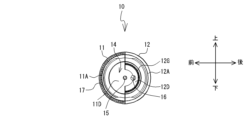
図1に示すドライブレコーダ1は、事故時及び急制動時等において、その発生前後の一定期間についての前方映像とドライバーの運転操作(ブレーキ操作、ウインカー操作、走行経路等)状況を示す走行データとを記憶可能な構成となっている。映像データの記憶をする構成について簡単に説明すると、CCDカメラ13にて常時、運転者の視点(視野)から自車と周辺状況を撮像するとともに、その撮像した映像をリングバッファ等の一時記憶メモリに記憶する。この一時記憶メモリに記憶する映像は、逐次最新のものに更新され、設定された時間分だけ過去の映像データが保持される。一方、ドライブレコーダ1は、加速度センサ等の事故や急ブレーキ・急ハンドル時に発生する衝撃を検知するセンサを備え、そのセンサの出力値が閾値を超えた場合、閾値を超えた(衝撃検出)時点より前の一定期間の映像を一時記憶メモリから読み出して不揮発性メモリ(SDメモリカード等)に格納すると共に、閾値を超えた時点以降はその後に撮像したCCDカメラの映像を不揮発性メモリに直接或いは一時記憶メモリを経由して格納することで衝撃前及び衝撃後の所定時間にわたる映像と前記走行データ等を不揮発性メモリ(SDカード)に保存する機能を備える。そして、事故が発生したときには、不揮発性メモリに保存されている自車の車両状況情報(映像等)に基づいて、運転者の正当性を明確に証言することを可能としている。また、ドライブレコーダ1は、急ハンドル、急ブレーキ等の乱暴で危険な運転操作を検出すると、警告音等を発して運転者に注意を促すことで、運転者にある種の緊張感を与えることもできる。ドライブレコーダ1は、車両の前方映像を撮影し記憶することから、通常、車両のフロントガラス101(図29,図30参照)等に取り付けた状態で、使用される。
The
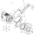
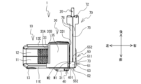
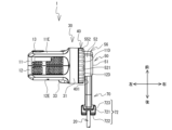
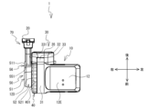
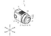
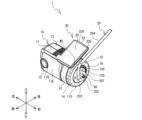
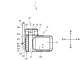
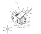
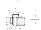
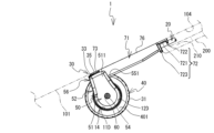
図1~図8を参照し、ドライブレコーダ1の構造を説明する。ドライブレコーダ1は、平面視L字状に構成されたユニット(図6,図7参照)であって、ケース10、取付用ブラケット30、ナット部材40、ガイドカバー50、ネジ60、ケーブルカバー70等を備える。ケース10は、左右方向に延びる軸心を備える略円筒形状に形成され、その正面にCCDカメラ13を備える。取付用ブラケット30は、ケース10の右端側(軸心方向)の一端側にリング部31が回転可能に装着され、そのリング部31に連結する取付板33が、車両のフロントガラス101の取付位置P1(図29参照)に接着して固定される。取付位置P1は、例えば、フロントガラス101において、車室の天井部に設けられたルーフヘッドライニング200の縁に沿って設けられた黒セラライン210から下方に離れる所定位置に設定される。取付位置P1は、例えば、黒セラライン210から下方に距離L1、車両中心Oから左方向に距離L2の位置に設定される。ナット部材40はリング状に形成され、ケース10の右端側に装着されている。ナット部材40は、取付用ブラケット30に対してケース10を固定する。
The structure of the
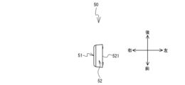
ガイドカバー50は、ケース10の右端側に、ケース10の軸心と同軸上に回転可能に設けられる。ガイドカバー50は、ケース10の右側面14(図2参照)から引き出されるケーブル20(図2,図14参照)のうち、右側面14から取付板33に隣接する位置までを覆い隠す。ケーブル20は、例えば電源ケーブルであるが、その他のケーブルでもよく、複数本の配線が束になったハーネスでもよい。また、一本ではなく複数本であってもよい。ネジ60は、ガイドカバー50をケース10の右側面14に回転可能に支持すると共に固定する。ケーブル20は、ガイドカバー50の上部後方の角部に設けられた開口部55から、取付板33に対して平行に引き出される。図30に示すように、車両のフロントガラス101に取り付けられた状態では、ケーブル20は、例えばフロントガラス101に沿うようにして上方に出され、ルーフヘッドライニング200の黒セラライン210の内側に引き込まれ、車両内部の電源供給部(図示略)に接続される。ケーブルカバー70は、ガイドカバー50の開口部55からルーフヘッドライニング200の黒セラライン210までのケーブル20に沿って外側から取り付けられる。
The
上記構成を有するドライブレコーダ1は、ケース10に対して、取付用ブラケット30のリング部31を回転可能に装着する。それ故、取付用ブラケット30の取付板33とケース10との相対角度位置を変更できる。車両のフロントガラス101(図30参照)の傾斜角度は、車両の種類によって異なるが、取付板33とケース10との相対角度位置を変更することによって、ドライブレコーダ1は、一つのユニット構成で異なる種類の車両に対応できる。以下、ドライブレコーダ1の構成部品を順に説明する。
In the
図9,図10を参照し、ケース10の構造を説明する。ケース10は、略円筒形状に形成されている。ケース10は、前後で2分割(半割)された第1ケース11と第2ケース12とを突き合わせることで構成されている。第1ケース11,第2ケース12の一方端部11A,12Aは、その外形寸法が一回り小さく形成され、その一方端部11A,12Aと、ケース10軸心方向の中央部位との間には段差が形成されている。この段差を生じた壁面のうち、一方端部11A側において、三角波状(鋸刃状)のセレーションである歯部17が右側面視半円弧状に形成されている。第1ケース11,第2ケース12の右方に突出する一方端部11A,12Aの先端側外周面には、雄ねじ18が形成されている。
9 and 10, the structure of the
一方端部11A,12Aの先端側には、右側面視小半円状の凸部11D,12Dが設けられている。凸部11D,12Dは、右方に突出する略円柱状の凸部を構成する。その凸部の右側面14は、右側面視略円形状に形成されている(図10参照)。右側面14には、ネジ孔15、引出口16、歯部12G等が設けられている。ネジ孔15は、右側面14の中心部に設けられている。ネジ孔15には、ガイドカバー50を回転可能に固定する為のネジ60(図2参照)が締結される。引出口16は、ネジ孔15の後方であって、凸部12D側に設けられている。引出口16からは、ケーブル20が右側方に引き出される。引出口16は、右側面14の中心部から後方にずれている。それ故、ガイドカバー50を回転可能に固定する為のネジ孔15を、右側面14の中心部に設けることができる。よって、ガイドカバー50を、ケース10の軸心と同軸上で、且つ右側面14の中心部で回転させることができる。
At the tip side of one
歯部12Gは、右側面14の凸部12D側において、歯部17と向かい合う位置で、歯部17よりも径の小さい右側面視半円弧状に形成されている。歯部12Gは、歯部17と同一ピッチの三角波状(鋸刃状)に形成されている。歯部12Gには、ガイドカバー50の後述する歯部58(図11,図14参照)が噛み合うようになっている。なお、歯部12Gの位置は、右側面14のうち、右側面14の中心部を取り囲む位置であればどこでもよいが、右側面14の中心部よりも外側にあった方が望ましい。この場合、歯部12Gにおいて細かくピッチを刻むことができる。また、歯部12Gのピッチについても限定しないが、狭いよりも広い方が望ましい。これにより、ガイドカバー50を回転させる角度を作り易い。また、歯部12Gは半円弧状に形成されているが、円弧状であれば長さについては限定しない。例えば、右側面14の中心部を一周取り囲む円形状にしてもよいが、本実施形態のケース10は二分割されているので、歯部12Gは半分で十分である。
The
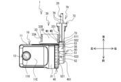
図5~図8に示すように、第1ケース11と第2ケース12は、接合面と反対側の表面が接合面と平行な平坦面11E,12Eとなる。よって、これら平坦面11E,12Eは、互いに平行に設定されている。図9に示すように、ケース10の正面の一部である平坦面11Eであって、その左端側の上下方向の中間部の位置には、円形状の開口部11Bが形成されている。その開口部11Bの内側には、CCDカメラ13がケース10の内側から前方に突出して設けられている。CCDカメラ13の視野の方向は、平坦面11Eと直交する方向に設定されている。また、ケース10の左側面には、SDカードスロット22(図5参照)が設けられている。SDカードスロット22には、SDカード(図示略)が着脱される。
As shown in Figs. 5 to 8, the
図2を参照し、取付用ブラケット30の構造を説明する。取付用ブラケット30は、リング部31、連結柱部32(図5参照)、取付板33等を備える。リング部31は、リング状に形成され、第1ケース11,第2ケース12の一方端部11A,12Aの外径に略一致(若干大きい)する内径を有する。連結柱部32は、リング部31の外周面に起立して設けられる。取付板33は、連結柱部32の先端に設けられ、平面視前後方向にやや長い略矩形状に形成されている(図6参照)。取付板33は、リング部31の直径方向に対して、所定角度に斜め傾斜状に配置されている(図5参照)。取付板33の上側に向けられた被取付面33Aには、所定の厚みを有する台座面33Bが設けられている。台座面33Bは、平面視矩形状のフロントガラス101に取り付ける為に一段高く形成されている。その台座面33Bには、両面テープ35が貼着されている。なお、両面テープ35の接着面は、例えば複数の矩形状の小片部に分割されていてもよい。両面テープ35は、剥離紙を剥がすことによって接着部が露出される。さらに、取付板33の被取付面33Aの右端側の前寄りの位置には、マークM1が設けられている。マークM1は、取付板33に対してガイドカバー50の位置を合わせるときの基準となる。マークM1の形状は何でもよいが、例えば左右方向に延びる直線状のマークにすることで、位置合わせが容易となる。
2, the structure of the mounting
リング部31の片面(ケース10に対向する面)には、その全周に渡って歯部34が形成されている。歯部34は、三角波状(鋸刃状)に形成され、ケース10に形成した歯部17と噛み合うように、同一寸法形状に設定されている。リング部31を第1ケース11,第2ケース12の一方端部11A,12Aに装着すると、リング部31はその中心軸を回転中心として、第1ケース11,第2ケース12の一方端部11A,12Aに対して相対的に、例えば5°ピッチで正逆方向に回転させることができる。そして、ケース10に設けた歯部17と、リング部31に設けた歯部34とを噛み合わせることで、回転が抑止される。
One side of the ring portion 31 (the side facing the case 10) has
図2を参照し、ナット部材40の構造を説明する。ナット部材40は、扁平な円盤状のキャップ状形態からなり、その内周面41に、雄ねじ18と螺合する雌ねじ41Aが形成されている。ナット部材40の中央部には、円形状の貫通孔42が形成されている。その貫通孔42の周囲を取り囲む蓋面401は、径方向内側になるにつれて外側に膨らむカーブを有する曲面となっている。取付用ブラケット30のリング部31を、第1ケース11,第2ケース12の一方端部11A,12Aに装着した状態では、雄ねじ18は、リング部31よりも外側(右方)に突出する。そこで、その突出した雄ねじ18に対してナット部材40を装着する。そして、ナット部材40の雌ねじと、ケース10の雄ねじ18とをしっかりと締結することで、ナット部材40と、ケース10の歯部17を形成した段差部分までの間隔が狭くなるので、ケース10とナット部材40との間でリング部31を所定の力で挟み付けることができる。これにより、取付用ブラケット30に対してケース10がしっかりと固定される。
The structure of the
しっかりと固定した状態では、歯部17,34同士が噛み合ってリング部31ひいては取付用ブラケット30の回転が抑止され、ナット部材40を緩めた状態では、当該回転が許容される。よって、ケース10と取付用ブラケット30との相対角度位置を任意の位置に設定(調整)すると共に、その位置で固定できる。つまり、第1ケース11と第2ケース12の接合面と平行な面(方向)をケース10の基本の上下方向とした場合、その上下方向と取付用ブラケット30の取付板33とのなす角を変更できる。
When firmly fixed, the
さらに、ナット部材40をしっかりと締結することで、ケース10の歯部17と取付用ブラケット30の歯部34とがしっかりと噛み合ってその回転が確実に阻止されるので、仮に事故等によりドライブレコーダ1に衝撃が加わったとしても、ケース10の向き・姿勢は、ドライブレコーダ1をフロントガラス101に取り付けたときの基本姿勢を維持し(取付板33がフロントガラス101から剥がれ落ちない限り)、しっかりと固定できる。
Furthermore, by firmly fastening the
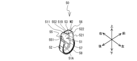
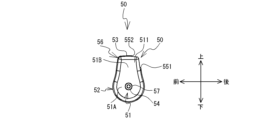
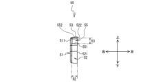
図2,図11~図17を参照し、ガイドカバー50の構造を説明する。ガイドカバー50は、右側面視略ひょうたん型に形成されている(図2,図13参照)。ガイドカバー50は、断面コの字型の蓋状に形成され、例えば左方側に内側を向けるようにして配置される。ガイドカバー50は、側壁部51と周壁部52を備える。側壁部51は上下方向に延びる右側面視略ひょうたん型の平板状に形成され、右側方から見た場合に、円形状の円形部51Aと、その円形部51Aの上部から上方に突出する矩形状の矩形部51Bとを備える。円形部51Aの中心部には、厚み方向に貫通する孔部54が設けられている。円形部51Aの内側の面であって、孔部54に対応する位置には、筒状の軸部57が円形部51Aの内面に対して垂直に設けられている。軸部57の軸孔は、孔部54と連通している。周壁部52は、側壁部51の外縁部に沿って設けられ、該外縁部から左方に延びる略筒状に形成されている。周壁部52の左右方向の長さである幅B1(図12参照)は、例えば、ケーブル20を内側に収容できる程度の長さに設定されている。
The structure of the
このような側壁部51と周壁部52で構成されるガイドカバー50は、側壁部51に設けられた軸部57を中心に径方向外側に突出する突出部56を形成し、その突出部56以外の部分は、径方向内側に縮径している。そのような突出部56の周壁部52における上部後方の角部には、開口部55が設けられている(図11,図14,図15参照)。開口部55の位置は、側壁部51の矩形部51Bの上部後方の角部の位置に対応する。開口部55は、背面視左側に開口する略コの字型の切欠き状に形成されている(図11,図17参照)。周壁部52は、開口部55によって上部後方位置で分断されている。コの字型の開口部55の下辺は、周壁部52の一端部である下側端部551によって形成されている。開口部55の上辺は、周壁部52の他端部である上側端部552によって形成されている。開口部55の右辺は、側壁部51の矩形部51Bによって形成されている。下側端部551は、開口部55の下辺に対して下方から突出する。上側端部552は、開口部55の上辺に対して前方から略水平に突出する。上側端部552は、側壁部51の矩形部51Bの上部後方の角部よりも前方に位置する。下側端部551は、上側端部552よりも後方に位置する。よって、ガイドカバー50が、ケース10の右側面14に取り付けられた状態では、開口部55は、上方の一部と後方が開口する態様となる。このような開口部55の右側には、側壁部51の上部後方の角部に設けられた後述する隠し板部511が配置されている。
The
そして、突出部56の上端部に位置する周壁部52には、上側端部552から前方に延びる平面である平坦部53が形成されている。平坦部53は、側壁部51の矩形部51Bの上端部から、ケース10の右側面14側である左方に向かって、やや左上りに傾斜している(図12,図17参照)。平坦部53の上面の左端側には、マークM2が設けられている。マークM2は、取付板33の被取付面33Aに設けられたマークM1との位置合わせに用いられる。マークM2の形状は何でもよいが、例えばマークM1と同一形状である左右方向に延びる直線状にすることで、位置合わせが容易である。
The
ここで、図17に示すように、開口部55を後方から見た場合において、周壁部52の下側端部551は、ケース10の右側面14側である左方に向かって、やや左下がりに傾斜している。さらに、上述したように、平坦部53は、左方に向かってやや左上りに傾斜している。このことから、開口部55は、略台形状に形成されている。平坦部53を、左方に向かってやや左上りに傾斜させていることによって、ガイドカバー50の側壁部51を小さくできるので、ガイドカバー50をよりコンパクトに見せることができる。また、開口部55の左右方向の長さ(ガイドカバー50の軸方向に平行な長さ)である幅B2(図17参照)は、後述するケーブルカバー70の端部73の幅K1(図1参照)と同一、又は幅K1よりもやや短くなっている。このような開口部55に対して、ケーブルカバー70の端部73が隙間なく保持される。ケーブルカバー70の端部73と、開口部55との位置関係については後述する。
Here, as shown in FIG. 17, when the
図12,図17に示すように、ガイドカバー50をケース10の右側面14に固定した状態では、周壁部52の左端部521は、ケース10側に配置される。その左端部521において、平坦部53に対応する部分は、右方に一段低くなった段部522が形成されている。後述するように、左端部521のうち段部522以外の部分は、ケース10の右側面14と、その周囲に配置されるナット部材40の蓋面401とに近接して配置される部分である。よって、段部522以外の部分は、特に蓋面401の面形状に合わせて、上下方向中央部がやや右方に湾曲している。これにより、ガイドカバー50の左端部521を、ケース10の右側面14と、ナット部材40の蓋面401とに対して寄せて配置できるので、ガイドカバー50がケース10の一部分であるかのような一体感を持たせることができる。
12 and 17, when the
一方、段部522は、取付板33の右端部331との間に隙間を空けて、干渉しないようになっている。これにより、ガイドカバー50の突出部56の先端部を、取付板33の右端部331に可能な限り寄せて配置できるので、開口部55を、取付板33に隣接する位置に配置できる。そして、取付板33に隣接する位置に対して、開口部55からケーブル20を引き出すことができるので、開口部55において、ケーブル20が車両のフロントガラス101から浮いて離れてしまうのを防止できる。
On the other hand, a gap is provided between the
そのようなガイドカバー50の左端部521には、その略下半分である半円弧状の部分に渡って歯部58(図11,図14参照)が形成されている。歯部58は、三角波状(鋸刃状)のセレーションであって、ケース10の右側面14に形成した歯部12G(図9,図10参照)と噛み合うように、同一寸法形状に設定されている。ガイドカバー50をケース10の右側面14に配置し、ネジ60を孔部54と軸部57を介して、右側面14の中心部に設けられたネジ孔15に緩く締結することで、ガイドカバー50はネジ60を回転中心として、ケース10の右側面14に対して相対的に正逆回転させることができる。そして、ガイドカバー50に設けられた歯部58を、ケース10の右側面14に設けられた歯部12Gに噛み合わせることで、回転が抑止される。また、本実施形態では、歯部12Gと58のピッチは、歯部17と34のピッチと同一に設定されているので、ケース10に対するガイドカバー50の回転ピッチを、取付板33に対するケース10の回転ピッチに合わせることができる。これにより、取付板33に対するケース10の相対角度位置が変更された場合に、ケース10に対するガイドカバー50の位置を合わせ易い。
The
そして、上記構造を備えるガイドカバー50は、突出部56以外の部分が径方向内側に縮径し、右側面視略ひょうたん型、若しくは涙型に形成されているので、ケース10とほぼ同径の円形にしたガイドカバーに比べて小さくできる。これにより、ケース10にガイドカバー50が固定された構造物全体を目立なくコンパクトにできる。
The guide cover 50 with the above structure has a diameter that is reduced radially inward except for the protruding
図2を参照し、ケーブルカバー70の構造を説明する。ケーブルカバー70は、例えば直線状に形成されたゴム製のラバー部材である。ケーブルカバー70は、外縁が断面矩形状に形成され、その内部には、長さ方向に延びるケーブル挿通孔74を備える。ケーブルカバー70の長さ方向に対して平行な一面には、フロントガラス101に接着等で固定する為の固定面76が設けられている。固定面76には、長さ方向に直交する幅方向の中央を分断するように、切欠き溝75が設けられている。切欠き溝75は、ケーブル挿通孔74に連通している。それ故、切欠き溝75を幅方向に押し広げることで、ケーブル20をケーブル挿通孔74の内側に押し込むことができる。また、切欠き溝75の幅よりも、ケーブル挿通孔74の幅の方が長くなっているので、ケーブルカバー70は、ケーブル挿通孔74の内側にケーブル20を抱え込むことができる。それ故、ケーブル20からケーブルカバー70が離脱してしまうのを防止できる。
The structure of the
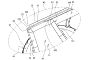
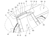
このようなケーブルカバー70の長手方向の一端部には、挿入部72が設けられている。挿入部72は、車両のルーフヘッドライニング200の黒セラライン210(図29,図30参照)の内側に挿入させる部位である。挿入部72は、側面視略U字状に形成され、例えば、横板部721、第一立壁部722、第二立壁部723等を備える。横板部721は、ケーブルカバー70の中央部よりも幅広の平面視略矩形状に形成されている。第一立壁部722と第二立壁部723は、ケーブルカバー70の長手方向において互いに離間した位置で、固定面76とは反対側に立設されている。挿入部72においても、固定面76、ケーブル挿通孔74、切欠き溝75が形成されている。このような挿入部72において、第一立壁部722と第二立壁部723の間に、ルーフヘッドライニング200の黒セラライン210の屈曲する端部が挿入される(図30参照)。これにより、黒セラライン210の端部は、第一立壁部722と第二立壁部723の間に挟持される。よって、挿入部72のうち、横板部721と第一立壁部722が、黒セラライン210の内側に挿入される。そして、横板部721と第一立壁部722は、ルーフヘッドライニング200と、フロントガラス101の上端部に隣接して設けられる板金104との間に形成された空間内に配置される。よって、挿入部72は、ルーフヘッドライニング200と、板金104との間に挟持された状態となる。横板部721と第一立壁部722は、黒セラライン210の内側に挿入され、第二立壁部723が黒セラライン210の端部の外面に当接している。これにより、第一立壁部722の下部に設けられたケーブル挿通孔74の開口から引き出されるケーブル20を、ルーフヘッドライニング200の内側に引き出して配置できる。
An
後述するが、ケーブルカバー70は、車両のフロントガラス101に設定される取付位置P1(図29参照)に応じて、その長さ寸法を調節する必要がある。その場合、ケーブルカバー70の長さ(具体的には、ケーブルカバー70の端部73から挿入部72の第二立壁部723までの長さ)が、距離L1に対応する長さとなるように、ケーブルカバー70の挿入部72とは反対側の他端部であって、ガイドカバー50の開口部55の位置に配置される端部73側をハサミ等で切断すればよい。これにより、挿入部72を残した状態で、ケーブルカバー70の長さ寸法を調節できる。なお、本実施形態のケーブルカバー70の材質は、ゴム以外の材質でもよいが、切断する必要性があることから、望ましくは弾性体がよく、より望ましくは、やわらかい材質が好ましい。例えば、ゴムの他に、エラストマー等でもよい。また、柔らかければ、手で押し開きながら取り付けることができるので、取り付けが簡単である。また、弾性体であることから、直線状のケーブルカバー70を曲げることができるので、車両のフロントガラス101の面形状に合わせて密着して固定できる。さらに、ケーブルカバー70の色は何でもよいが、ケーブル20を覆って隠す必要があるので、不透明であるのが望ましく、より望ましくは、不透明でガイドカバー50と同一色にするのがよい。これにより、ガイドカバー50との一体感を強めることができる。
As will be described later, the length of the
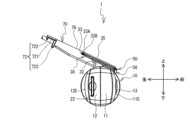
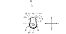
図18~図20を参照し、ケース10の右側面14の引出口16から引き出されるケーブル20の取り回し態様について説明する。上述のように、本実施形態では、軸心を左右方向に向けたケース10の右側面14(軸方向から)からケーブル20を引き出している。これは、取付板33に対してケース10が回転して相対角度位置が変わった場合でも、ケーブル20をフロントガラス101側に一旦引き出してから、フロントガラス101に沿わせ、ルーフヘッドライニング200に向かって立ち上げることができるからである。そして、本実施形態では、引出口16から引き出されたケーブル20を、フロントガラス101側に引き出してフロントガラス101に沿わせるまでの間に、ガイドカバー50の内側において、以下の様な複数の方向転換が行われる。これによって、取付板33に対するケース10の相対角度位置がどのように変わっても、ケーブル20の取り回しによって生じるケーブル20のテンションの影響を低減しつつ、車両のフロントガラス101の面に沿って、ケーブル20を無理なく引き出すことができる。
18 to 20, the manner in which the
ケーブル20にかかるテンションと、ケーブル20の方向転換によるテンションの逃がし効果について具体的に説明する。仮に、ケーブル20を引き出す引出口16がフロントガラス101側に近い場合、ケーブル20はS字を描いてしまう。この場合、フロントガラス101側に対して立つ方向にケーブル20のテンションが掛かってしまうので、ガイドカバー50はケーブル20によって下方向に付勢されてしまう。そして、ケーブル20のテンションが過剰に強くなってしまうと、ガイドカバー50の内側にケーブル20を押し込むことができず、ケース10の右側面14に対し、ガイドカバー50を取り付けることが困難になる。
The tension on the
そこで、本実施形態では、図18~図20に示すように、引出口16からケーブル20を右側方に引き出した後、右側面14に対して平行な方向に曲げ、その右側面14に対して平行な仮想平面内において、ネジ孔15の外側を円弧状にぐるっと回して取付板33側に引き出し、そのまま取付板33と平行な方向に引き出している。これにより、フロントガラス101に沿う方向にケーブル20のテンションが自然にかかる。即ち、ケーブル20のテンションを、取付板33と平行な方向な真っ直ぐな方向にそのまま逃がすことができる。これにより、ガイドカバー50が下方向に付勢されるのを効果的に防止できる。
In this embodiment, as shown in Figures 18 to 20, the
そして、上述の通り、引出口16は、ケース10の右側面14の中心部からずれた位置に設けられているので、引出口16から引き出したケーブル20について、右側面14の中心部の外側をぐるっと回すことができる。なお、引出口16の位置は、右側面14の中心部以外の位置であればどこでもよいが、望ましくは、ガイドカバー50の開口部55に対して、近くよりも遠く離れた位置にある方がよい。仮に、引出口16が開口部55に近い位置にあると、特にケーブル20が太かったり、硬かったりした場合は、ケーブル20を曲げることによるテンションが強くなってしまう。よって、引出口16は、開口部55から遠い位置にある方が、ケーブル20を右側面14の中心部の外側を無理なく回すことができる。
As described above, the
本実施形態では、ケーブル20の方向転換による取り回しを、ひょうたん型のガイドカバー50の内側において行っている。ここで、例えば、引出口16から引き出されるケーブル20について、引出口16からケーブル20を右側方に引き出す部分までを第1部分201、右側方に引き出した部分からネジ孔15の外側を円弧状にぐるっと回した部分までを第2部分202、円弧状にぐるっと回した部分から取付板33側に引き出した部分までを第3部分203、取付板33側に引き出した部分から取付板33と平行な方向に曲げて直線状に引き出した部分を第4部分204とする。
In this embodiment, the
上述の通り、ガイドカバー50は、円形状の本体部分から径方向外側に突出する突出部56を備えている。図19に示すように、そのようなガイドカバー50の内側には、ケーブル20の第1部分201から第3部分203までが収容される。そして、ケーブル20の第3部分203の前側には、ケーブル20の突出部56の根元部分が位置している。突出部56の根元部分は、円形状の本体部分に連結する部分であるため、ガイドカバー50の径方向内側にやや縮径するように湾曲している(図13参照)。このような湾曲部分の周壁部52が、第3部分203の前側に沿うように配置されることから、ケーブル20の第3部分203を開口部55側に寄せることができる。これにより、ケーブル20を無理に曲げることなく、開口部55から直線状に引き出すことができる。
As described above, the
また、本実施形態では、取付板33に対してケース10を回転させて相対角度位置を変更する場合がある。このとき、引出口16は、右側面14において、ガイドカバー50の軸心を中心に、仮想的な同一平面内を円弧状に移動する(図19中に示す矢印参照)だけである。それ故、引出口16は左右方向(ガイドカバー50の軸線方向)に大きく移動することが無い。これにより、引出口16から引き出されて、上記のように方向転換されるケーブル20も、左右方向に大きく移動することが無い。よって、ケーブル20の第1部分201から第3部分203までを覆うガイドカバー50の側壁部51を、ケース10の右側面14に対して平行な平板状に形成することができる。これにより、ガイドカバー50が右側方に大きく出っ張らないので(図3参照)、ケース10の左側面からガイドカバー50の側壁部51までの横方向の寸法を、できるだけ小さくコンパクトにまとめることができる。
In addition, in this embodiment, the
また、引出口16は、右側面14において、ガイドカバー50の軸心を中心に、仮想的な同一平面内を円弧状に移動するので、そのような引出口16から引き出されるケーブル20の移動に合わせて、ガイドカバー50の少なくとも引出口16が移動する範囲に対応する部分の外縁形状を円弧状にできる。これにより、ガイドカバー50の形状を、丸味を帯びた柔らかい印象を持たせることができる。
In addition, the
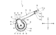
図21~図26を参照し、ケース10に固定されたガイドカバー50の開口部55の位置と、その開口する方向について説明する。ガイドカバー50がケース10の右側面14に固定された状態では、突出部56の先端部は、取付用ブラケット30の取付板33の右端部331に隣接する位置に配置される。ここで、図26に示すように、突出部56の先端部に設けられた平坦部53は、取付板33の被取付面33Aに対して同一高さ、且つ平行になるように配置される。開口部55は、そのような突出部56の周壁部52であって上部後方の角部に設けられているので、上方の一部と後方が開口する態様となる。開口部55の上辺である上側端部552は、取付板33の傾斜方向と平行で、後方に対して斜め上方に向いている(図21,図22、図24参照)。一方、開口部55の下辺である下側端部551は、取付板33側に対して略垂直方向に向いている(図23,図24参照)。このような位置関係によって、開口部55は、取付板33の右端部331に隣接する位置において、取付板33の被取付面33Aに対して平行な方向に向くことになる。
21 to 26, the position of the
そして、図26に示すように、このような開口部55付近において、ケーブル20は平坦部53の内面に接触し、そのまま上側端部552の向く方向に引き出される。つまり、ケーブル20は、開口部55から取付板33の被取付面33Aに沿う方向に引き出される。これにより、開口部55から引き出されたケーブル20の第4部分204を、取付板33の被取付面33Aが取り付けられる車両のフロントガラス101(図29,図30参照)に沿わせることができる。
As shown in FIG. 26, the
そして、ガイドカバー50の開口部55が上記位置に設定された状態では、取付板33の被取付面33Aの右端部331側の前寄りの位置に設けられたマークM1に対して、ガイドカバー50の平坦部53の上面の左端側に設けられたマークM2が対向配置されるようになっている(図1,図6参照)。例えば、取付板33に対してケース10を回転して相対角度位置を変更した場合、取付板33に対する開口部55の位置はずれてしまう。この場合、マークM1に対してマークM2が対向配置するように、ケース10の右側面14に対してガイドカバー50の相対角度位置を変更すればよい。また、仮に、マークM1とM2を備えていなくても、例えば、取付板33に対して、ケース10を正方向にX°回転させて位置を固定した場合、ケース10の軸心と同軸上において、ガイドカバー50をケース10に対して、負方向にX°回転させればよい。これにより、取付板33に対する開口部55の位置を、元の状態に戻すことができる。
When the
図1~図8、図27を参照し、ガイドカバー50の開口部55と、ケーブルカバー70の端部73との相互の位置関係について説明する。ケース10の右側面14の引出口16から引き出されるケーブル20のうち、第1部分201から第3部分203までは、ガイドカバー50で覆われる。開口部55から直線状に引き出されたケーブル20の第4部分204には、直線状のケーブルカバー70が取り付けられる。第4部分204に取り付けた状態で、ケーブルカバー70の端部73は、ガイドカバー50の開口部55に配置される。ここで、開口部55の右側には、ガイドカバー50の隠し板部511が配置され、開口部55の左側には、ナット部材40の蓋面401が夫々配置されている(図27参照)。そして、ケーブルカバー70の端部73は、これら隠し板部511と蓋面401の間に挿入される。ここで、開口部55の左右方向の長さである幅B2(図17参照)は、ケーブルカバー70の幅K1(図1参照)よりもやや短くなっているので、開口部55において、ケーブルカバー70の端部73を押し込むようにして挿入される。
With reference to Figures 1 to 8 and 27, the relative positions of the
また、ケーブルカバー70の高さK2(図4参照)は、開口部55の高さB3(図17参照)よりも高くなっているので、開口部55に対して、ケーブルカバー70の端部73を挿入すると、ケーブルカバー70の端部73は、開口部55の上側端部552に対して当接する。これにより、ケーブルカバー70の端部73は、ガイドカバー50の突出部56の奥側までは挿入されないようになっている。これは、上述したように、ガイドカバー50の突出部56の内側では、ケーブル20の第3部分203が開口部55に向かって斜めにガイドされているので、その部分に対してケーブルカバー70の端部73が当接して邪魔にならないようになっている。また、ケーブルカバー70がガイドカバー50の奥側(前側)まで挿入されてしまうと、ケーブル20を急な角度で曲げなければいけない。そこで、本実施形態のように、ガイドカバー50の突出部56の内側において、開口部55にケーブルカバー70の端部73の一部だけが挿入されることによって、引出口16からネジ孔15の外側を回して取付板33側に引き出されたケーブル20を無理なく曲げた状態で、開口部55にガイドすることができる。
In addition, since the height K2 (see FIG. 4) of the
ケーブルカバー70は、ガイドカバー50の平坦部53よりも上方に突出して配置される。なお、ケーブルカバー70の端部73側の外表面と、ガイドカバー50の開口部55の下側端部551との間には、隙間が形成されているが、当接させてもよい。ケーブルカバー70の端部73は、ガイドカバー50の隠し板部511と、ナット部材40の蓋面401とによって左右方向の両側から挟持されている。これにより、開口部55に対して、ケーブルカバー70の端部73の位置をしっかりと固定できるので、ケーブルカバー70の端部73が開口部55から離れて、車両のフロントガラス101から浮いて宙吊り状態になるのを防止できる。
The
そして、開口部55に対して、ケーブルカバー70の端部73が固定された状態を右側方から見ると、ケーブルカバー70の端部73の外表面に対して、ガイドカバー50の隠し板部511が、ケーブルカバー70の長さ方向に対して平行な方向にオーバーラップして重なっている。この状態では、隠し板部511と重なっている部分と同一の高さ位置において、ケーブルカバー70のケーブル挿通孔74が位置している。それ故、ケーブル挿通孔74に挿通されているケーブル20は、隠し板部511によって確実に隠れるので、外部からは全く見えないようにできる。これにより、ガイドカバー50の開口部55と、ケーブルカバー70の端部73との継ぎ目部分を、隠し板部511によって隠すことができるので、この継ぎ目部分においてもケーブル20を露出させないようにできる。
When the
また、車両のフロントガラス101に取り付けられた状態のドライブレコーダ1を、フロントガラス101側から見た場合において(図3,図30参照)、ガイドカバー50の開口部55の上側端部552に対して、ケーブルカバー70の端部73が当接しているので(図27参照)、ケーブル20がガイドカバー50とケーブルカバー70に隠れて露出しない。さらに、ケーブルカバー70の切欠き溝75はフロントガラス101側に位置するが、ケーブル20に取り付けた状態では、切欠き溝75は殆ど閉じた状態であるので、その下方に位置するケーブル挿通孔74に挿通されるケーブル20は全く見えない。さらに、上述した通り、ケーブルカバー70の挿入部72は、車室のルーフヘッドライニング200の黒セラライン210の内側に挿入して取り付けられる(図30参照)。
When the
従って、本実施形態では、ケース10の右側面14の引出口16から引き出されたケーブル20のうち、第1部分201から第3部分203までをガイドカバー50で覆い、第4部分をケーブルカバー70で覆い、さらに、ガイドカバー50の開口部55とケーブルカバー70の端部73との継ぎ目部分を、開口部55に設けられた隠し板部511で覆い、ケーブルカバー70の端部73とは反対側の挿入部72を、黒セラライン210の内側に挿入して取り付けることによって、ドライブレコーダ1のケーブル20を隠すことができる。これにより、ケース10と車室のルーフヘッドライニング200との間に引き出されて露出していたケーブル20を隠すことができるので、その部分の見栄えを向上できる。さらに、ケース10は、ガイドカバー50とケーブルカバー70を介して、ルーフヘッドライニング200と繋がっているように見えるので、ドライブレコーダ1と車両との間に一体感を持たせることができるので、ドライブレコーダ1の後付け感が低減され、ドライブレコーダ1をあたかも自動車の純正品のように見せるようにできる。さらに、例えば、ケース10、ガイドカバー50、ケーブルカバー70を同一色にすることで、ドライブレコーダ1が一つの構造物として強く認識させることができる。
Therefore, in this embodiment, the
また、ケーブル20を覆い隠すガイドカバー50と、ケーブルカバー70は、ケーブル20の形状とは異なり、ガイドカバー50についてはひょうたん状にコンパクトな形状にし、ケーブルカバー70については、ケーブル20の可撓性を全く感じさせない直線状の柱状物にしていることから、ケーブル20の存在を消すことができる。さらに、ケーブルカバー70は、ガイドカバー50の開口部55から、ケース10の軸心方向に対して直交する方向に延び、車室のルーフヘッドライニング200の黒セラライン210に対して垂直方向に接続するように配置されている。これにより、ケース10、ケーブルカバー70、及び黒セラライン210がH字状に配列されることから、見栄えが綺麗である。
The
また、ケーブルカバー70の固定面76を、フロントガラス101に両面テープ等で固定することで、ケーブル20を、ガイドカバー50とケーブルカバー70によって隠すことができると共に、空中配線になるのを防止できる。空中配線については、自動車メーカに直接部品を供給する企業であるティア1は厳しい基準を設けているが、そのようなティア1に対しても、本実施形態は、十分に基準を満たすドライブレコーダ1を提供することができる。
In addition, by fixing the fixing
図28~図30を参照し、車両のフロントガラス101へのドライブレコーダ1の取付方法の一例を説明する。先ず、フロントガラス101の傾斜角度に合せて、取付板33に対するケース10の相対角度位置を変更する(図28参照)。上記の通り、ドライブレコーダ1は、各種フロントガラスの角度(25~75度)に合わせて調整可能である。つまり、取付板33は、フロントガラス101の角度と平行になるが、上述のように、取付板33(取付用ブラケット30)に対するケース10の相対角度位置を調整できるので、取付板33(フロントガラス)の角度に関係なく、ケース10を基本の上下方向を例えば垂直面(地面に対する)と平行にすることができる。勿論、ケース10を基本の上下方向と、地面に対する垂直面とのなす角を適宜の角度に設定することもできる。従って、1つのドライブレコーダ1にて、異なる種類の車両に実装することができる。
With reference to Figures 28 to 30, an example of a method for mounting the
次いで、ガイドカバー50のケース10に対する相対角度位置を変更する。上述した通り、本実施形態では、取付板33の被取付面33Aに設けられたマークM1に対して、ガイドカバー50の平坦部53に設けられたマークM2が対向配置するように、ケース10の右側面14に対してガイドカバー50の相対角度位置を変更すればよい。これにより、ガイドカバー50の開口部55を、取付板33に隣接する位置において、取付板33の被取付面33Aに対して平行な方向に向けることができる。
Next, the relative angular position of the
次いで、フロントガラス101の取付位置P1(図29参照)に、取付用ブラケット30の取付板33を固定する。取付板33の上面には、両面テープ35(又は、その他の接着部材)が取り付けられ、その両面テープ35を用いて、車両のフロントガラス101に接着して固定する(図30参照)。この状態において、ガイドカバー50の突出部56の平坦部53は、取付板33の台座面33Bと平行、且つ同一高さ位置である。台座面33Bは、両面テープ35によって、フロントガラス101に接着されている。ここで、図30に示すように、ガイドカバー50の突出部56の平坦部53は、フロントガラス101から離れて浮いた状態となるので、接触しない。これにより、例えば車両走行中の振動によって、ガイドカバー50がフロントガラス101に衝突する等して、その衝撃がケース10に伝わり、ケース10内の電子部品が衝撃を感知して、ドライブ誤作動を起こすのを防止できる。
Next, the mounting
次いで、開口部55からルーフヘッドライニング200までの最短距離を計測する。計測距離に合せて、ケーブルカバー70の一端側をはさみで切断すればよい。ケーブル20にケーブルカバー70を組み付ける。ケーブルカバー70の端部73をガイドカバー50の開口部55に配置する。このとき、ケーブルカバー70の挿入部72を、ルーフヘッドライニング200の黒セラライン210内に収める。ケーブルカバー70の端部73を、上述のように、ガイドカバー50の開口部55に配置し、隠し板部511とナット部材40の蓋面401との間に挿入させて保持させる。これにより、ドライブレコーダ1の取り付けが完了する。
Next, measure the shortest distance from the
ドライブレコーダ1は、ケース10、ガイドカバー50、ケーブルカバー70が一体となった構造物として認識させ易く、さらには、ルーフヘッドライニング200と一体となった構造物として認識させ易い。よって、ドライブレコーダ1は、あたかも車両の純正品であるかのような印象を周囲に与えることができる。
The
また、ケース10の軸心方向に対して、ケーブルカバー70が直交する方向に配置されるので、平面視逆L字状の構造物として認識されるので、ルーフヘッドライニング200の一部であるかのような印象を与えることができる。
In addition, since the
取付用ブラケット30の取付板33と、ケーブルカバー70が互いに寄せた位置に夫々配置されているので、一体感がある。これにより、コンパクトでかっこよくスタイリッシュに見せることができる。また、取付板33のみならず、ケーブルカバー70もフロントガラス101に接着して固定されているので、二重でドライブレコーダ1をフロントガラス101に対して固定できる。これにより、ドライブレコーダ1を強固にフロントガラス101に対して固定できるので、事故が起きたときにドライブレコーダ1の落下を防止できる。
The mounting
また、本実施形態のドライブレコーダ1は、例えば、取付用ブラケット30だけをフロントガラス101に残すことができる。つまり、取付用ブラケット30以外の部分、即ち、ケース10、ガイドカバー50、及びケーブルカバー70を、他の車両に移すことができる。これにより、取付用ブラケット30を、フロントガラス101から取り外さなくてもよいので、例えば、フロントガラス101に両面テープ35の接着剤がこびりついて、それらを剥がす作業を不要にできる。
In addition, with the
上記説明において、ドライブレコーダ1は本発明の「機器」の一例である。ガイドカバー50とケーブルカバー70は本発明の「カバー部材」の一例である。ガイドカバー50は本発明の「第一カバー部材」の一例である。ケーブルカバー70は本発明の「第二カバー部材」の一例である。ルーフヘッドライニング200は本発明の「隠し部材」の一例である。ケース10は本発明の「筐体」の一例である。隠し板部511は本発明の「隠し部材」の一例である。ネジ60は本発明の「固定部」の一例である。ケース10の右側面14は本発明の「所定面」、及び「側面」の一例である。ガイドカバー50の平坦部53は本発明の「平坦面」の一例である。取付用ブラケット30は本発明の「支持手段」の一例である。
In the above description, the
以上説明したように、本実施形態のドライブレコーダ1は、車両のフロントガラス101の取付位置P1に取り付けられるケース10を有する。ドライブレコーダ1は、ケース10の右側面14からケーブル20を引き出し、そのケーブル20のケース10側とは反対側の部分を、車両のフロントガラス101に連続して設けられるルーフヘッドライニング200の内側に引き込まれるようにしている。ドライブレコーダ1は、そのようなケーブル20のうち、ケース10の右側面14から引き出されて、ルーフヘッドライニング200によって隠れる位置までの部分を、ガイドカバー50とケーブルカバー70で覆う。これにより、ドライブレコーダ1から引き出されたケーブル20は外部に露出しないので、ケース10とルーフヘッドライニング200の間の見栄えを向上できる。さらに、ガイドカバー50とケーブルカバー70は、ケース10とルーフヘッドライニング200の間のケーブル20を覆うことから、ケース10がガイドカバー50とケーブルカバー70を介してルーフヘッドライニング200と繋がっているように見えるので、ドライブレコーダ1と車両との間に一体感を持たせることができる。
As described above, the
また、本実施形態では、ガイドカバー50とケーブルカバー70を、別体にして備えている。ガイドカバー50は、ケーブル20の右側面14から取付板33に隣接する位置までの部分を覆い、ケーブルカバー70は、ケーブル20の取付板33に隣接する位置から車両のフロントガラス101に沿って引き出され、ルーフヘッドライニング200によって隠れる位置までの部分を覆う。ケーブル20を隠す部分を、ガイドカバー50とケーブルカバー70とで役割分担させることで、夫々の部分を確実に覆うことができる。そして、そのようなガイドカバー50の開口部55と、ケーブルカバー70の端部73との継ぎ目となる部分において、ガイドカバー50の開口部55に設けられた隠し板部511が配置されている。隠し板部511は、ケーブルカバー70の端部73の外表面と重なっているので、ガイドカバー50の開口部55とケーブルカバー70の端部73との継ぎ目に隙間が形成されない。これにより、ガイドカバー50とケーブルカバー70によって、ケース10の右側面14から車両のフロントガラス101に沿う方向に引き出されて、ルーフヘッドライニング200に引き込まれる部分までを綺麗に隠すことができる。
In addition, in this embodiment, the
なお本発明は、上述の実施形態に限定されず、種々の変更が可能である。本実施形態は、機器の一例として、ドライブレコーダ1を説明したが、電子部品を備える機器であれば何でも良く、車載機器に限定するものはない。
The present invention is not limited to the above-described embodiment, and various modifications are possible. In this embodiment, a
また、本実施形態のドライブレコーダ1は、取付用ブラケット30を備え、その取付用ブラケット30の取付板33を、車両のフロントガラス101に取り付けて、ケース10を回転可能に支持するものであるが、例えば、ケース10を車両のフロントガラス101に接着等で固定するタイプにも適用可能である。その場合、例えば、フロントガラス101の取付位置P1に取り付けるケース10の面とは異なる所定面からケーブルを引き出すようにすればよい。
The
また、ガイドカバー50は、突出部56以外の外縁部を縮径したひょうたん型であるが、これ以外の形状でもよく、例えば、円形状にしてもよい。この場合、ケース10との一体感を強めることができる。
The
また、本実施形態のドライブレコーダ1では、取付用ブラケット30の取付板33が、ケーブル20が引き出されるケース10の右側面14側に寄せた位置に配置されているが、例えば、ケース10の左側面側に寄せた位置に配置されてもよく、ケース10の左右方向の中間部に配置するようにしてもよい。
In addition, in the
また、本実施形態では、引出口16からケーブル20をケース10から引き出すようにしているが、引出口16の代わりに、例えばDCジャック等の接続部を設けてもよい。DCジャックに、ケーブルの一端を接続することによって、ケース10の右側面14からケーブルを引き出すようにしてもよい。
In addition, in this embodiment, the
また、本実施形態では、ケース10の右側面14からケーブル20を引き出しているが、ケース10の他の面からケーブル20を引き出すようにしてもよい。
In addition, in this embodiment, the
また、本実施形態では、ガイドカバー50とケーブルカバー70の二つのカバー部材で、ケーブル20を覆うようにしているが、ガイドカバー50とケーブルカバー70を一つの部材で構成してもよい。また、ガイドカバー50を一つの部材ではなく、二つ以上の部材で構成してもよい。ケーブルカバー70においても一つの部材ではなく、二つ以上の部材で構成してもよい。
In addition, in this embodiment, the
また、本実施形態では、ケース10の右側面14において、引出口16から引き出されたケーブル20を、ネジ孔15の外側をぐるっと回してから、取付板33側に出しているが、例えば、引出口16から引き出されたケーブル20をそのまま開口部55側にガイドするようにしてもよい。
In addition, in this embodiment, the
以上、本発明の様々な側面を実施形態並びに変形例を用いて説明してきたが、これらの実施形態や説明は、本発明の範囲を制限する目的でなされたものではなく、本発明の理解に資するために提供されたものであることを付言しておく。本発明の範囲は、明細書に明示的に説明された構成や限定されるものではなく、本明細書に開示される本発明の様々な側面の組み合わせをも、その範囲に含むものである。本発明のうち、特許を受けようとする構成を、添付の特許請求の範囲に特定したが、現在の処は特許請求の範囲に特定されていない構成であっても、本明細書に開示される構成を、将来的に特許請求の範囲とする意思を有する。本願発明は上述した実施の形態に記載の構成に限定されない。上述した各実施の形態や変形例の構成要素は任意に選択して組み合わせて構成するとよい。また各実施の形態や変形例の任意の構成要素と、発明を解決するための手段に記載の任意の構成要素または発明を解決するための手段に記載の任意の構成要素を具体化した構成要素とは任意に組み合わせて構成するとよい。これらについても本願の補正または分割出願等において権利取得する意思を有する。また、意匠出願への変更出願により、全体意匠または部分意匠について権利取得する意思を有する。図面は本装置の全体を実線で描画しているが、全体意匠のみならず当該装置の一部の部分に対して請求する部分意匠も包含した図面である。例えば当該装置の一部の部材を部分意匠とすることはもちろんのこと、部材と関係なく当該装置の一部の部分を部分意匠として包含した図面である。当該装置の一部の部分としては、装置の一部の部材としても良いし、その部材の部分としても良い。全体意匠はもちろんのこと、図面の実線部分のうち任意を部分を破線部分とした部分意匠を権利化する意思を有する。 Although various aspects of the present invention have been described above using embodiments and modifications, it should be noted that these embodiments and descriptions are not intended to limit the scope of the present invention, but are provided to aid in the understanding of the present invention. The scope of the present invention is not limited to the configurations explicitly described in the specification, but includes combinations of various aspects of the present invention disclosed in this specification. The configurations of the present invention for which a patent is sought are specified in the attached claims, but even if the configurations are not currently specified in the claims, the intention is to include the configurations disclosed in this specification in the claims in the future. The present invention is not limited to the configurations described in the above-mentioned embodiments. The components of each of the above-mentioned embodiments and modifications may be arbitrarily selected and combined. In addition, any component of each embodiment or modification may be arbitrarily combined with any component described in the means for solving the invention or any component embodying any component described in the means for solving the invention. The intention is to obtain rights to these as well through amendments to this application or divisional applications, etc. In addition, the intention is to obtain rights to the entire design or partial design by filing a conversion application to a design application. The drawings show the entire device in solid lines, but they include not only the overall design but also partial designs claimed for a portion of the device. For example, it is possible to claim a partial design for a part of the device, regardless of the part. A part of the device may be a part of the device, or it may be a part of that part. We intend to claim partial designs by drawing any part of the solid line part of the drawings as a dashed line part, as well as the overall design.
1 ドライブレコーダ
10 ケース
11 第1ケース
13 CCDカメラ
14 右側面
15 ネジ孔
16 引出口
20 ケーブル
30 取付用ブラケット
33 取付板
33A 被取付面
50 ガイドカバー
51 側壁部
53 平坦部
55 開口部
56 突出部
60 ネジ
70 ケーブルカバー
72 挿入部
73 端部
101 フロントガラス
104 板金
200 ルーフヘッドライニング
210 黒セラライン
M1 マーク
M2 マーク
P1 取付位置
REFERENCE SIGNS
Claims (2)
車両のガラスに接着して固定され、前記筐体を前記ガラスに取り付けるためのブラケットであって、前記筐体を前記筒の軸を中心に回転可能にして前記筐体に装着されるブラケットと、
前記筐体のうち、前記筐体の前記回転に応じて視野の方向が変化する位置に設けられたカメラと、
前記筐体の内部から前記筒の底面に相当する面側である前記筐体の側面側の引出口を通じて前記筐体の外部に引き出され、さらに前記ガラスに近づく方向に引き出されたケーブルが通される溝であって、前記ガラスの側に開口しており、かつ前記筐体側の位置から前記ガラス側の位置まで延びている溝と、
前記筐体の前記側面側に設けられ、前記ケーブルのうちの前記筐体の内部から引き出された部分の周辺を隠す部材であって、前記筐体に対して前記軸を中心として回転可能に設けられる部材と、
を備える車載機器。 A cylindrical housing;
a bracket that is adhesively fixed to a glass of a vehicle and is used to attach the housing to the glass, the bracket being attached to the housing in such a manner that the housing can rotate around an axis of the tube;
a camera provided at a position on the housing such that a direction of a field of view changes in response to the rotation of the housing;
a groove through which a cable is passed that is drawn from inside the housing to the outside of the housing through an outlet on a side surface of the housing, which is the surface side corresponding to the bottom surface of the tube, and that is drawn in a direction approaching the glass, the groove opening on the glass side and extending from a position on the housing side to a position on the glass side;
a member provided on the side surface of the housing, for concealing a periphery of a portion of the cable that is pulled out from inside the housing, the member being rotatable about the axis with respect to the housing;
An in-vehicle device comprising:
Priority Applications (2)
| Application Number | Priority Date | Filing Date | Title |
|---|---|---|---|
| JP2022141184A JP7621665B2 (en) | 2020-09-23 | 2022-09-06 | device |
| JP2024090511A JP7833805B2 (en) | 2020-09-23 | 2024-06-04 | device |
Applications Claiming Priority (2)
| Application Number | Priority Date | Filing Date | Title |
|---|---|---|---|
| JP2020158097A JP7364233B2 (en) | 2016-10-25 | 2020-09-23 | device |
| JP2022141184A JP7621665B2 (en) | 2020-09-23 | 2022-09-06 | device |
Related Parent Applications (1)
| Application Number | Title | Priority Date | Filing Date |
|---|---|---|---|
| JP2020158097A Division JP7364233B2 (en) | 2016-10-25 | 2020-09-23 | device |
Related Child Applications (1)
| Application Number | Title | Priority Date | Filing Date |
|---|---|---|---|
| JP2024090511A Division JP7833805B2 (en) | 2020-09-23 | 2024-06-04 | device |
Publications (2)
| Publication Number | Publication Date |
|---|---|
| JP2022184869A JP2022184869A (en) | 2022-12-13 |
| JP7621665B2 true JP7621665B2 (en) | 2025-01-27 |
Family
ID=74165406
Family Applications (2)
| Application Number | Title | Priority Date | Filing Date |
|---|---|---|---|
| JP2022141184A Active JP7621665B2 (en) | 2020-09-23 | 2022-09-06 | device |
| JP2024090511A Active JP7833805B2 (en) | 2020-09-23 | 2024-06-04 | device |
Family Applications After (1)
| Application Number | Title | Priority Date | Filing Date |
|---|---|---|---|
| JP2024090511A Active JP7833805B2 (en) | 2020-09-23 | 2024-06-04 | device |
Country Status (1)
| Country | Link |
|---|---|
| JP (2) | JP7621665B2 (en) |
Citations (3)
| Publication number | Priority date | Publication date | Assignee | Title |
|---|---|---|---|---|
| US20070091626A1 (en) | 2005-10-21 | 2007-04-26 | Hook Richard R | Wire cover assembly for vehicle interior mirror |
| JP2010105530A (en) | 2008-10-30 | 2010-05-13 | Yupiteru Corp | On-vehicle equipment |
| JP2013112314A (en) | 2011-11-30 | 2013-06-10 | Hitachi Automotive Systems Ltd | Installation device of on-vehicle camera |
Family Cites Families (1)
| Publication number | Priority date | Publication date | Assignee | Title |
|---|---|---|---|---|
| JP2003291726A (en) * | 2002-04-03 | 2003-10-15 | Denso Corp | Vehicle overhead module |
-
2022
- 2022-09-06 JP JP2022141184A patent/JP7621665B2/en active Active
-
2024
- 2024-06-04 JP JP2024090511A patent/JP7833805B2/en active Active
Patent Citations (3)
| Publication number | Priority date | Publication date | Assignee | Title |
|---|---|---|---|---|
| US20070091626A1 (en) | 2005-10-21 | 2007-04-26 | Hook Richard R | Wire cover assembly for vehicle interior mirror |
| JP2010105530A (en) | 2008-10-30 | 2010-05-13 | Yupiteru Corp | On-vehicle equipment |
| JP2013112314A (en) | 2011-11-30 | 2013-06-10 | Hitachi Automotive Systems Ltd | Installation device of on-vehicle camera |
Also Published As
| Publication number | Publication date |
|---|---|
| JP7833805B2 (en) | 2026-03-23 |
| JP2022184869A (en) | 2022-12-13 |
| JP2024116211A (en) | 2024-08-27 |
Similar Documents
| Publication | Publication Date | Title |
|---|---|---|
| JP4712858B2 (en) | Car equipment | |
| JP5085943B2 (en) | Power feeding device for slide structure | |
| US11890994B2 (en) | On-board bracket for on-board device at vehicle | |
| JP2012157176A (en) | Protector for wire harness | |
| JP7621665B2 (en) | device | |
| JP7364233B2 (en) | device | |
| JP5728708B2 (en) | Car equipment | |
| JP6771762B2 (en) | machine | |
| JP6291645B2 (en) | Car equipment | |
| JP2020030184A (en) | External sensor | |
| JP2011140304A (en) | Onboard equipment | |
| EP1674340A1 (en) | Outer mirror with front view arrangement | |
| JP5489021B2 (en) | Car equipment | |
| CN110857070B (en) | External sensor | |
| JP2006281966A (en) | Mounting structure of on-vehicle mounting part | |
| US7222895B2 (en) | Device for storing article protecting automobile body | |
| JP4055533B2 (en) | Automotive meter mounting structure | |
| JP7717406B2 (en) | In-vehicle equipment and drive recorders | |
| JP6771788B2 (en) | Mounting member | |
| JP6682715B2 (en) | In-vehicle equipment and drive recorder | |
| JP6492154B2 (en) | Car equipment | |
| JP2006290056A (en) | Sunshade device for vehicle | |
| JP2015157627A (en) | On-vehicle apparatus | |
| JP2023111586A (en) | Vehicular mirror device | |
| JP2009119941A (en) | Image display part-storing type equipment and in-vehicle information equipment |
Legal Events
| Date | Code | Title | Description |
|---|---|---|---|
| A621 | Written request for application examination |
Free format text: JAPANESE INTERMEDIATE CODE: A621 Effective date: 20220927 |
|
| A131 | Notification of reasons for refusal |
Free format text: JAPANESE INTERMEDIATE CODE: A131 Effective date: 20231024 |
|
| A521 | Request for written amendment filed |
Free format text: JAPANESE INTERMEDIATE CODE: A523 Effective date: 20231222 |
|
| A02 | Decision of refusal |
Free format text: JAPANESE INTERMEDIATE CODE: A02 Effective date: 20240305 |
|
| A521 | Request for written amendment filed |
Free format text: JAPANESE INTERMEDIATE CODE: A523 Effective date: 20240604 |
|
| A911 | Transfer to examiner for re-examination before appeal (zenchi) |
Free format text: JAPANESE INTERMEDIATE CODE: A911 Effective date: 20240612 |
|
| A912 | Re-examination (zenchi) completed and case transferred to appeal board |
Free format text: JAPANESE INTERMEDIATE CODE: A912 Effective date: 20240816 |
|
| A61 | First payment of annual fees (during grant procedure) |
Free format text: JAPANESE INTERMEDIATE CODE: A61 Effective date: 20250107 |
|
| R150 | Certificate of patent or registration of utility model |
Ref document number: 7621665 Country of ref document: JP Free format text: JAPANESE INTERMEDIATE CODE: R150 |