JP7621647B2 - Sheet ceiling - Google Patents
Sheet ceiling Download PDFInfo
- Publication number
- JP7621647B2 JP7621647B2 JP2021124241A JP2021124241A JP7621647B2 JP 7621647 B2 JP7621647 B2 JP 7621647B2 JP 2021124241 A JP2021124241 A JP 2021124241A JP 2021124241 A JP2021124241 A JP 2021124241A JP 7621647 B2 JP7621647 B2 JP 7621647B2
- Authority
- JP
- Japan
- Prior art keywords
- sheet
- shaped
- ceiling
- action member
- support frames
- Prior art date
- Legal status (The legal status is an assumption and is not a legal conclusion. Google has not performed a legal analysis and makes no representation as to the accuracy of the status listed.)
- Active
Links
Images


Landscapes
- Tents Or Canopies (AREA)
Description
本発明は、可撓性のシートが拡げられてなるシート天井に関するものである。 The present invention relates to a sheet ceiling made of a stretched flexible sheet.
特許文献1には、部屋の壁に固定されたL形棒材からなる支持フレームと、支持フレームの水平フランジの端部上に設けられた肩部と、支持フレームの内側に横方向に拡げられたシートと、シートの各側面上に取り付けられて肩部に掛け止めされているステープル(U形釘)形式の縁と、部屋の天井に固定されたプーリーを巡って通過するケーブルとを具備したシート天井が記載されている。
そして、ケーブルの垂直側の下端に掛け止めされた重量物が、シートの少なくとも一点に調節自在な下方への作用力を及ぼして、シートを審美的に下方へ変形させる。審美性は、重量物の接触点の形状(球形や星形)から生じる。 A weight attached to the lower vertical end of the cable exerts an adjustable downward force on at least one point of the seat, causing the seat to deform downward in an aesthetic way. The aesthetic comes from the shape of the weight's contact point (spherical or star-shaped).
あるいは、ケーブルの垂直側の下端に掛け止めされたスポットライトのような照明装置が、シートの少なくとも一点に調節自在な上方への作用力を及ぼして、シートを審美的に上方へ変形させる。 Alternatively, a lighting device such as a spotlight hung on the lower end of the vertical side of the cable exerts an adjustable upward force on at least one point of the seat to aesthetically deform the seat upward.
特許文献1では、シートの少なくとも一点に調節自在な上下方向の作用力を及ぼすため、シートは上に凸又は下に凸の点状ピークを有する変形をする。すると、シートの点状ピーク部位に作用力が集中して、同部位が伸びたり傷んだりするおそれがある。
In
そこで、本発明の目的は、シートに上に凸又は下に凸のライン状ピークを有する変形をさせることにより、シートのライン状ピーク部位にかかる作用力を分散させて、該部位が伸びたり傷んだりしないようにすることにある。また、このライン状ピークを有する変形により、シート天井に新しい審美性(見た目の美しさ)をもたらすことにある。 The object of the present invention is to disperse the force acting on the linear peak portion of the sheet by deforming the sheet to have a linear peak that is convex upward or downward, thereby preventing said portion from stretching or being damaged. In addition, this linear peak deformation is intended to bring new aesthetics (visual beauty) to the sheet ceiling.
本発明のシート天井は、部屋の対向する壁に固定された、長さ方向が壁幅方向である支持フレームと、対向する支持フレームの間に拡げられた可撓性のシートと、シートの辺縁を支持フレームに接続する接続具と、シートの中間部を調節可能に上げて又は下げてシートを変形させるシート変形装置とを含むシート天井において、
シート変形装置が、シートに上に凸又は下に凸のライン状ピークを有する変形をさせるものであることを特徴とする。
The sheet ceiling of the present invention includes support frames fixed to opposing walls of a room, the length direction of which is the wall width direction, a flexible sheet stretched between the opposing support frames, connectors for connecting edges of the sheet to the support frames, and a sheet deformation device for adjustably raising or lowering a middle portion of the sheet to deform the sheet,
The sheet deforming device is characterized in that it deforms the sheet to have a line-shaped peak that is convex upward or convex downward.
ここで、接続具が、シートの辺縁に取り付けられて支持フレームに掛け止めされた掛け止め具であることが好ましい。 Here, it is preferable that the connector is a hook attached to the edge of the sheet and hooked to the support frame.
(作用)
シート変形装置が、シートに上に凸又は下に凸のライン状ピークを有する変形をさせるため、シートのライン状ピーク部位にかかる作用力は該ライン状ピーク部位の全体に均一に分散する。
シートのライン状ピークを有する変形は、見栄えがよい。
(Action)
Since the sheet deforming device deforms the sheet to have a linear peak that is convex upward or downward, the force acting on the linear peak portion of the sheet is uniformly distributed over the entire linear peak portion.
The deformation of the sheet having line-like peaks looks good.
本発明のシート天井によれば、シートに上に凸又は下に凸のライン状ピークを有する変形をさせることにより、シートのライン状ピーク部位にかかる作用力を分散させて、該部位が伸びたり傷んだりしないようにすることができる。また、このライン状ピークを有する変形により、シート天井に新しい審美性(見た目の美しさ)をもたらすことができる。 According to the sheet ceiling of the present invention, by deforming the sheet to have a linear peak that is convex upward or downward, it is possible to disperse the force acting on the linear peak portion of the sheet, preventing said portion from stretching or being damaged. Furthermore, this deformation with a linear peak can bring new aesthetics (beauty of appearance) to the sheet ceiling.
<1>シート
可撓性のシートとしては、特に限定されないが、布、樹脂シート、これらを複合したシート等を例示できる。布の材料としては、有機繊維、無機繊維等を例示できる。
<1> Sheet The flexible sheet is not particularly limited, but examples thereof include cloth, resin sheet, composite sheet of these, etc. Examples of cloth materials include organic fibers, inorganic fibers, etc.
<2>支持フレーム
支持フレームとしては、特に限定されないが、型材(金属が所定の断面形状で押出成形されてなるもの)を例示できる。型材の断面形状としては、特に限定されないが、L(アングル)、コ(チャンネル)、T、H、角管等を例示できる。
<2> Support frame The support frame is not particularly limited, but examples thereof include a molded material (a metal extrusion molded into a predetermined cross-sectional shape). The cross-sectional shape of the molded material is not particularly limited, but examples thereof include an L (angle), a C (channel), a T, an H, a square tube, etc.
<3>掛け止め具
掛け止め具としては、特に限定されないが、シートの辺縁を掴む掴持部と、支持フレームに掛止する部位とを含むものを例示できる。
掛け止め具は、支持フレームと平行である長さ方向の長さが200~2000mmであり、シートの辺縁に複数の掛け止め具が、隣り合う掛け止め具の間の間隔が50mm以下であるように、取り付けられていることが好ましい。
この掛け止め具の長さは300~1800mmがより好ましく、500~1500mmが最も好ましい。なお、複数の掛け止め具のうちの一部は、部屋の壁幅に応じてまちまちであるシートの辺幅にアジャストするように、長さを200mm未満としてもよい。
この掛け止め具の間隔は30mm以下がより好ましく、10mm以下が最も好ましい。
<3> Hooking Device The hanging device is not particularly limited, but an example thereof includes a gripping portion that grips the edge of the sheet and a portion that is hung on the support frame.
It is preferable that the length of the hanging device in the longitudinal direction parallel to the support frame is 200 to 2000 mm, and that a plurality of hanging devices are attached to the edge of the sheet so that the interval between adjacent hanging devices is 50 mm or less.
The length of the hanging fixture is more preferably 300 to 1800 mm, and most preferably 500 to 1500 mm. Note that some of the hanging fixtures may have a length of less than 200 mm so as to adjust to the side width of the sheet, which varies depending on the wall width of the room.
The interval between the latches is more preferably 30 mm or less, and most preferably 10 mm or less.
<4>シート変形装置
シート変形装置は、シートに上に凸又は下に凸のライン状ピークを有する変形をさせるものであることが好ましい。
シートの変形におけるライン状ピークの長さは、特に限定されないが、シートのライン状ピーク部位にかかる作用力が大きく分散される点で1000mm以上が好ましく、1500mm以上がより好ましく、2000mm以上がさらに好ましい。ライン状ピークの長さの上限は、特になく、部屋の大きさにより制約される。
<4> Sheet Deforming Device The sheet deforming device is preferably one that deforms the sheet to have an upwardly or downwardly convex line-shaped peak.
The length of the linear peak in the deformation of the sheet is not particularly limited, but is preferably 1000 mm or more, more preferably 1500 mm or more, and even more preferably 2000 mm or more, in order to largely disperse the force acting on the linear peak portion of the sheet. There is no particular upper limit to the length of the linear peak, and it is limited by the size of the room.
ライン状ピークは、その全長にわたって高さのばらつきが小さいことが好ましく、具体的には、ぱらつき量(ライン状ピークの最高部と最低部との差)が200mm以下が好ましく、100mm以下がより好ましく、50mm以下が最も好ましい。上に凸のライン状ピークの場合、シートの中間部の下面にシートよりも剛性が高いライン状作用部材を当てることにより、ぱらつき量を小さくすることができる。
ここで、ライン状は、平面視で直線状が好ましいが、緩やかな曲線状でもよい。
The linear peak preferably has a small variation in height over its entire length, and specifically, the variation (difference between the highest and lowest parts of the linear peak) is preferably 200 mm or less, more preferably 100 mm or less, and most preferably 50 mm or less. In the case of an upwardly convex linear peak, the variation can be reduced by applying a linear acting member having a higher rigidity than the sheet to the underside of the middle part of the sheet.
Here, the line shape is preferably a straight line in a plan view, but may be a gently curved line.
シート変形装置としては、特に限定されないが、次の(a)~(c)を例示できる。
(a)シートの中間部の下面に当てられた、シートよりも剛性が高く水平方向に延びるライン状作用部材と、該中間部をライン状作用部材とともに吊り上げる作動装置とを含むもの
(b)シートの中間部の上面に当てられた、シートよりも剛性が高く水平方向に延びるライン状作用部材と、該中間部をライン状作用部材とともに押し下げる作動装置とを含むもの
(c)シートの中間部を掴んだ、シートよりも剛性が高く水平方向に延びるライン状作用部材と、該中間部をライン状作用部材とともに吊り上げ又は押し下げる作動装置とを含むもの
The sheet deformation device is not particularly limited, but the following (a) to (c) can be exemplified.
(a) A device including a line-shaped acting member that is placed on the underside of the middle part of the seat, has higher rigidity than the seat, extends in the horizontal direction, and an operating device that lifts up the middle part together with the line-shaped acting member. (b) A device including a line-shaped acting member that is placed on the upper surface of the middle part of the seat, has higher rigidity than the seat, extends in the horizontal direction, and an operating device that pushes down the middle part together with the line-shaped acting member. (c) A device including a line-shaped acting member that is placed on the upper surface of the middle part of the seat, has higher rigidity than the seat, extends in the horizontal direction, and grasps the middle part of the seat, and an operating device that lifts up or pushes down the middle part together with the line-shaped acting member.
ライン状作用部材としては、特に限定されないが、棒状体、幅10~200mmの細幅板状体、型材等を例示できる。ライン状作用部材の長さは、特に限定されないが、後述するようにライン状ピークの長さを決めるから、1000mm以上が好ましく、1500mm以上がより好ましく、2000mm以上がさらに好ましい。
ライン状作用部材の材料としては、特に限定されないが、金属、樹脂等を例示できる。
作動装置としては、特に限定されないが、複数本の吊り線状体と、吊り線状体を引張・弛緩調節する調節機構とを含むものを例示できる。
吊り線状体としては、特に限定されないが、ワイヤー、ロープ、チェーン等を例示できる。
調節機構としては、特に限定されないが、ターンバックル、ロック機能付き巻き取り機構等を例示できる。
The linear action member is not particularly limited, but examples thereof include a rod-shaped body, a narrow plate-shaped body having a width of 10 to 200 mm, a molded material, etc. The length of the linear action member is not particularly limited, but since it determines the length of the linear peak as described later, it is preferably 1000 mm or more, more preferably 1500 mm or more, and even more preferably 2000 mm or more.
The material of the linear action member is not particularly limited, but examples thereof include metal and resin.
The operating device is not particularly limited, but an example thereof may include a device including a plurality of suspension wires and an adjustment mechanism for tensioning and loosening the suspension wires.
The suspension line body is not particularly limited, but examples thereof include a wire, a rope, and a chain.
The adjustment mechanism is not particularly limited, but examples thereof include a turnbuckle, a winding mechanism with a locking function, and the like.
複数本の吊り線状体の端部が壁の一箇所に集められ、該一箇所の近傍に調節機構が配されることが好ましい。 It is preferable that the ends of the multiple suspension wires are gathered at one point on the wall and that the adjustment mechanism is located near that point.
本発明を具体化した実施例のシート天井について、図面を参照して説明する。但し、本発明は実施例に限定されるものではなく、発明の趣旨から逸脱しない範囲で、数値、材料、接合手段等を適宜変更して具体化することもできる。 A sheet ceiling according to an embodiment of the present invention will be described with reference to the drawings. However, the present invention is not limited to the embodiment, and the values, materials, joining means, etc. can be appropriately changed without departing from the spirit of the invention.
[実施例1]
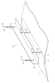
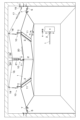
図1~図5に示す実施例1のシート天井は、シート1の中間部に上に凸のライン状ピーク2を有する谷型の変形をさせるものである。
シート天井は、部屋の対向する壁に固定された、長さ方向が壁幅方向である支持フレーム5と、対向する支持フレーム5の間に拡げられた可撓性のシート1と、シート1の辺縁に取り付けられて支持フレーム5に掛け止めされた複数の掛け止め具7と、シート1の対向する辺縁の間の中間部を調節可能に上げて又は下げてシート1を変形させるシート変形装置10とを含み構成されている。
[Example 1]
The sheet ceiling of the first embodiment shown in Figs. 1 to 5 has a valley-shaped deformation having an upwardly protruding
The sheet ceiling is composed of
なお、図2に示すように、部屋の別の対向する壁にも支持フレーム(図示略)が取り付けられ、シートの別の辺縁は複数の掛け止め具によりその支持フレームに掛け止めされている。当該別の対向する壁間の距離よりも、後述するシート変形装置10のライン状作用部材11は短く設定されているため、当該別の辺縁は水平となる。
As shown in FIG. 2, a support frame (not shown) is also attached to another opposing wall of the room, and another edge of the sheet is hooked to the support frame by a number of hooks. The
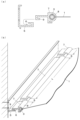
シート1は、例えばグラスファイバー(ガラス繊維)製である。図4に示すように、シート1の辺縁には厚さ方向に膨出した膨出部3が該辺縁に沿って延びるように形成されている。膨出部3は、例えば樹脂製の棒を芯材として辺縁に巻き込むことにより形成することができる。
The
図4に示すように、支持フレーム5は、アルミニウム合金製のL形型材であり、その縦部において壁にネジ止めされている。また、L形型材は、その横部の突端に縦部へ向かう返し部6が立設されている。
As shown in FIG. 4, the
図4に示すように、掛け止め具7は、アルミニウム合金製であり、膨出部3が係入することでシート1の辺縁を掴むC字状の掴持部8と、支持フレーム5の返し部6に掛止する部位としての返し部9とを一体的に含む。
掛け止め具7は、支持フレーム5と平行である長さ方向の長さLが200~2000mmである。
シート1の辺縁に複数の掛け止め具7が、隣り合う掛け止め具7の間の間隔Sが50mm以下であるように、取り付けられている。
As shown in Figure 4, the
The
A plurality of hanging
シート変形装置10は、シート1に上に凸のライン状ピーク2を有する山型の変形をさせるものである。
図1~図3に示すように、シート変形装置10は、
シート1の中間部の下面に当てられた、シート1よりも剛性が高く水平方向(対向する辺縁と平行)に延びるライン状作用部材11と、
シート1の中間部の上方にライン状作用部材11と平行に配されたシート上通し材12と、
ライン状作用部材11、シート1及びシート上通し材12を下方から順に貫通した複数のボルト13と、
シート上通し材12の上でボルトに調節可能に止められたナット14と、
シート1の中間部をライン状作用部材11等とともに吊り上げる作動装置15とを含み構成されている。
The
As shown in FIGS. 1 to 3, the
a
A sheet upper passing
A plurality of
a
The
ライン状作用部材11は、アルミニウム合金製で幅10~200mm(好ましくは20~100mm)の細幅板状体である。シート1はライン状作用部材11により下から支えられて変形し、上に凸のライン状ピーク2が生じる。よって、ライン状ピーク2の長さはライン状作用部材11の長さとはほぼ同じになり、本実施例ではライン状作用部材11の長さが1000mm以上であるから、ライン状ピーク2の長さも1000mm以上である。
シート上通し材12は、アルミニウム合金製のL形型材である。
複数のボルト13は、ライン状作用部材11の長さ方向に分散している。
The line-shaped
The upper
The
作動装置15は、複数本の吊り線状体16と、吊り線状体16を引張ったり繰り出したりして長さ調節する調節機構17とを含む。
吊り線状体16は例えばワイヤーであり、一端部がシート上通し材12に止められてそこから上方へ延び、中間部が部屋の天井に設けられたプーリー18に掛けられ、他端部が壁の止め具19に結合されている。図2に示すように、複数本の吊り線状体16の他端部が集められて、壁の一箇所の止め具19に結合されている。
調節機構17は、吊り線状体16の他端近傍に介装されたターンバックルである。
The operating
The hanging
The
ライン状作用部材11の剛性と、ボルト及びナットの調節と、調節機構17の調節により、ライン状ピーク2はその全長にわたって高さのばらつき量を50mm以下とすることができる。
By adjusting the rigidity of the
以上のように構成された実施例1のシート天井は、例えば次の[1]及び[2]のようにして施工することができる。
[1]シート1の掛け止め
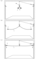
図5(a)に示すように、シート1の中間部からみて両側部を巻いた状態で、該中間部をシート変形装置10のライン状作用部材11の上に止める。次に、(b)に示すように、シート1の該両側部を巻き解いて横方向に拡げる。続いて、(c)に示すように、シート1の左右辺縁の掛け止め具7を支持フレーム5に掛け止めする。このとき、シート1の該両側部は下方へややたるんで軽く張った状態となる。
The sheet ceiling of Example 1 configured as described above can be installed, for example, as follows [1] and [2].
[1] Hanging of
(主たる作用効果)
掛け止め具7の長さLが200~2000mmであることにより、掛け止め具7の取扱性が非常によく、シート1の辺縁に取り付けやすい。
隣り合う掛け止め具7の間の間隔Sが50mm以下であることにより、隣り合う掛け止め具7の間のシート1が接近して皺になったり内側へ湾曲したりすることを防ぐことができ、シート1の辺縁が直線状になるようにして、見栄えを良くすることができる。
また、長さLが200~2000mmであり、且つ、間隔Sが50mm以下であるという組み合わせにより、シート1の辺縁部位にかかる引張力が分散し、同部位が伸びたり傷んだりしないようにすることができる。
(Main Effects)
Since the length L of the hanging
By making the interval S between the
Furthermore, by combining a length L of 200 to 2000 mm with a spacing S of 50 mm or less, the tensile force acting on the edge portions of the
(その他の作用効果)
・シート1を中間部で吊った状態で拡げて、壁に掛け止めすることができるので、作業が簡単になり、高度な技術を必要としない。
・シート1を床に広げないので、床に機械、配管等の物が置いてあってもシート1を張りでき、
・シート1を床に広げないので、床の養生やシート1のこすれ傷を減らせる。
・掛け止めは掛け止め具7の返し部を支持フレーム5の返し部に掛けるだけなので、高度な技術が必要なく、取り外しも簡単にできる。何度でも繰り返し使用できる。
・常時、シート1が掛け止め具7を引っ張っているので、掛け止めが外れない。
・掛け止め具7の返し部9と支持フレーム5の返し部6との合わせ面を斜めに加工することで、シート1の引張力を利用してくさびで締めるようにしっかり食い込ませて掛止することができる。
(Other Effects)
The
・Since the
-
The hook can be easily removed without requiring advanced skills, as all that is required to hook the
Since the
The mating surfaces of the return portion 9 of the
[2]シート1の変形
次に、上記のようにシート1の両側部が下方へたるんで軽く張った状態から、図1,2に示すように、調節機構17のターンバックルを操作して吊り線状体16を引っ張ることにより、シート1の中間部を吊り上げて、シート1に上に凸のライン状ピーク2を有する山型の変形をさせる。この変形によりシート1に張力が加わり、適度な張力が確保されて、シート天井が完成する。
[2] Deformation of
(主たる作用効果)
シート変形装置10が、シート1に上に凸のライン状ピーク2を有する変形をさせるため、シート1のライン状ピーク2部位にかかる作用力は該部位の全体に均一に分散する。よって、該部位が伸びたり傷んだりしないようにすることができる。
このライン状ピーク2を有する変形は、見栄えがよく、シート天井に新しい審美性をもたらすことができる。
(Main Effects)
Since the
This modification having
(その他の作用効果)
・シート1を水平に張る場合には、シート1に大きな張力を加える必要があるが、本実施例ではシート1を山型に張るので、シート1に適度な張力を加えれば足り、よって小さい吊り上げ力でもシート1をしっかり張れる。
・シート1を山型にすることで、スパンも例えば1/2と短くなるので、小さな力でもしっかり張れる。同じ張力でもたわみが小さくなる。
・シート1に大きな張力を加える場合には、シート1と取合う壁は鉄筋コンクリート造や鉄骨造の高強度壁に限定されるが、本実施例ではシート1に加える張力は適度なものなので、シート1と取合う壁は一般壁(普通の軽量鉄骨下地壁、木軸壁)でよく、施工範囲が大幅に広がる。
・壁に固定する支持フレーム5は、適度な張力に抗する軽量なもので足りる。
・万が一、地震などで吊り線状体16が外れても、シート1は辺縁で壁に掛け止めしてあるので、シート1は落下しない。
・複数本の吊り線状体16の端部が壁の一箇所に集められ、該一箇所の近傍に調節機構17(ターンバックル)が配されているので、シート1の吊り上げ量の調節、均一な張り具合の調整、定期点検等を効率的に行うことができる。
・ターンバックルによる調節は簡単であり、高度な技量を必要としない。
(Other Effects)
When stretching
・By making the
When a large tension is applied to
The
Even if the
Since the ends of the
-Adjustment using turnbuckles is easy and does not require advanced skills.
[実施例2]
図6に示す実施例2のシート天井は、調節機構17として、ターンバックルに代えて、吊り線状体16の他端部を調節可能に巻き取る巻き取り機構を用いた点において実施例1と相違し、その他は実施例1と共通である。
[Example 2]
The sheet ceiling of Example 2 shown in Figure 6 differs from Example 1 in that, instead of a turnbuckle, a winding mechanism that adjustably winds up the other end of the
巻き取り機構は、壁に取り付けられており、シート1よりも下方にある。但し、シート1よりも上方にあってもよい。
巻き取り機構は、巻き取り調節したところで吊り線状体16の繰り出しを止めるロック機能を備えている。
複数本の吊り線状体16は、それぞれの他端部が別々の巻き取り機構に巻き取られてもよいし、全他端部が一本の吊り線状体16に結合されたうえで一つの巻き取り機構に巻き取られてもよい。
The winding mechanism is mounted on the wall and is below the
The winding mechanism has a locking function that stops the unwinding of the
The other ends of the
実施例2によっても、実施例1と同様の作用効果が得られる。また、巻き取り機構はシート1よりも下方にあるため、室内で操作しやすい。
The second embodiment also provides the same effect as the first embodiment. In addition, the winding mechanism is located below the
[実施例3]
図7に示す実施例3のシート天井は、シート変形装置10が、シート1の中間部に下に凸のライン状ピーク2を有する谷型の変形をさせるものである点において実施例2と相違し、その他は実施例2と共通である。
[Example 3]
The sheet ceiling of Example 3 shown in Figure 7 differs from Example 2 in that the
シート変形装置10は、
シート1の上方でシート1の中間部を掴んだ、シート1よりも剛性が高く水平方向(対向する辺縁と平行)に延びるライン状作用部材11と、
ライン状作用部材11の上方に平行に配された上下動可能なスライダ21と、
ライン状作用部材11及びスライダ21を下方から順に貫通した複数のボルト22と、
スライダ21の上でボルトに調節可能に止められたナット23と、
部屋の天井に取り付けられて、スライダ21を上下動可能に案内する案内部材24と、
シート1の中間部をライン状作用部材11等とともに押し下げる作動装置15とを含み構成されている。
The
a
A
A plurality of
a
A
and an operating
シート1の中間部には厚さ方向に膨出した中間膨出部4が該中間部に沿ってライン状に延びるように形成されている。中間膨出部4は、例えば樹脂製の棒を芯材として辺縁に巻き込むことにより形成することができる。そして、ライン状作用部材11は、中間膨出部4が係入することでシート1の中間部を掴んだC字状でライン状に延びる掴持部11aと、ボルトが係止するフランジ部11bとを含む。
The
作動装置15は、複数本の吊り線状体16と、吊り線状体16を引張ったり繰り出したりして調節する調節機構17とを含む。
吊り線状体16は例えばワイヤーであり、一端部がスライダ21に止められてそこから上方へ延び、中間部が部屋の天井に設けられたプーリー25に掛けられ、他端部が調節機構17としての巻き取り機構に巻き掛けられている。
The operating
The
実施例3でもライン状作用部材11の長さが1000mm以上であるから、ライン状ピーク2の長さも1000mm以上である。
ライン状作用部材11の剛性と、ボルト22及びナット23の調節と、調節機構17の調節により、ライン状ピーク2はその全長にわたって高さのばらつき量を50mm以下とすることができる。
In the third embodiment, since the length of the
By adjusting the rigidity of the
実施例3のシート天井は、例えば次の[1]及び[2]のようにして施工することができる。
[1]シート1の掛け止め
実施例1における[1]と同様であり、シート1の両側部が下方へたるんで軽く張った状態とする。
[2]シート1の変形
上記の状態から、調節機構17の巻き取り機構を操作して吊り線状体16を繰り出すとともに、点検口20からスライダ21を押し下げてボルトにより案内部材24に固定することにより、スライダ21と共にライン状作用部材11を下動させ、シート1の中間部を押し下げて、シート1に下に凸のライン状ピーク2を有する谷型の変形をさせる。この変形によりシート1に張力が加わり、適度な張力が確保されて、シート天井が完成する。
The sheet ceiling of Example 3 can be constructed, for example, as follows [1] and [2].
[1] Hanging of
[2] Deformation of
実施例3によれば、下に凸のライン状ピーク2を有するシート1の変形により、実施例1,2とは異なる審美性が得られ、それ以外は基本的に実施例1,2と同様の作用効果が得られる。
According to Example 3, the deformation of the
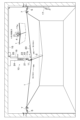
[実施例4]
図8に示す実施例4のシート天井は、シート1に3つの中間部を設定し、左右2つの中間部に、実施例1と同様のシート変形装置10により、上に凸のライン状ピーク2を有する谷型の変形をさせ、中央1つの中間部に、実施例3と同様のシート変形装置10により、下に凸のライン状ピーク2を有する谷型の変形をさせるものであり、その他は実施例1と基本的に共通である。
[Example 4]
The sheet ceiling of Example 4 shown in Figure 8 has three intermediate sections set in a
吊り線状体16は、左のシート変形装置10のプーリー18、中央のシート変形装置10の案内部材24のプーリー26、及び、左のシート変形装置10のプーリー18に掛けられて連続しており、調節機構17としてのターンバックルを介して、壁の一箇所の止め具19に結合されている。
The
実施例4のシート天井は、例えば次の[1]及び[2]のようにして施工することができる。
[1]シート1の掛け止め
シート1の3つの中間部を3つのシート変形装置10に止める。次に、シート1の左右辺縁の掛け止め具7を支持フレーム5に掛け止めする。このとき、シート1は4つの波状に下方へややたるんで軽く張った状態となる。
[2]シート1の変形
上記の状態から、調節機構17のターンバックルを操作して吊り線状体16を引っ張ることにより、左右2つの中間部に上に凸のライン状ピーク2を有する谷型の変形をさせ、それと相対的に、中央1つの中間部に下に凸のライン状ピーク2を有する谷型の変形をさせる。この変形によりシート1に張力が加わり、適度な張力が確保されて、シート天井が完成する。
The sheet ceiling of Example 4 can be constructed, for example, as follows [1] and [2].
[1] Hanging the
[2] Deformation of the
実施例4によれば、上に凸のライン状ピーク2を有するシート1の変形と、下に凸のライン状ピーク2を有するシート1の変形との組み合わせにより、変化のある審美性が得られ、それ以外は基本的に実施例1,2と同様の作用効果が得られる。
According to Example 4, a varied aesthetic appearance is obtained by combining a deformation of the
なお、実施例1と同様にしてシートの別の辺縁を水平にして別の対向する壁に掛け止めすることができるが、図8では、別の対向する壁間の距離とライン状作用部材11の長さとをほぼ同じ設定して、シートの別の辺縁を山谷状にしている。その場合は、図8にB-B断面を示すように、別の対向する壁に対してシートの別の辺縁を上下スライド可能にすればよい(金具を使って固定させない)。
As in the first embodiment, the other edge of the sheet can be hung horizontally on the other opposing wall, but in FIG. 8, the distance between the other opposing walls and the length of the
なお、本発明は前記実施例に限定されるものではなく、発明の要旨から逸脱しない範囲で適宜変更して具体化することができる。 The present invention is not limited to the above-mentioned examples, and can be modified as appropriate without departing from the spirit of the invention.
1 シート
2 ライン状ピーク
5 支持フレーム
7 掛け止め具
8 掴持部
10 シート変形装置
11 ライン状作用部材
15 作動装置
16 吊り線状体
17 調節機構
REFERENCE SIGNS
Claims (12)
シート(1)の辺縁には厚さ方向に膨出した膨出部(3)が該辺縁に沿って延びるように形成され、
接続具が、膨出部(3)が係入することでシート(1)の辺縁に取り付けられて支持フレーム(5)に掛け止めされた掛け止め具(7)であり、
シート変形装置(10)が、シート(1)に上に凸又は下に凸のライン状ピーク(2)を有する変形をさせるものであることを特徴とするシート天井。 A sheet ceiling includes support frames (5) fixed to opposing walls of a room, the length of which is in the width direction of the wall, a flexible sheet (1) stretched between the opposing support frames (5), connectors for connecting the edges of the sheet (1) to the support frames (5), and a sheet deformation device (10) for adjustably raising or lowering a middle portion of the sheet (1) to deform the sheet (1),
A bulge (3) is formed on the edge of the sheet (1) so as to extend along the edge in the thickness direction,
The connecting device is a hook (7) that is attached to the edge of the seat (1) and hooked to the support frame (5) by engaging the bulge (3),
A sheet ceiling characterized in that the sheet deformation device (10) deforms the sheet (1) to have a line-shaped peak (2) that is convex upward or downward.
シート変形装置(10)が、シート(1)に上に凸又は下に凸のライン状ピーク(2)を有する変形をさせるものであり、
シート変形装置(10)は、シート(1)の中間部の下面に当てられた、シート(1)よりも剛性が高く水平方向に延びるライン状作用部材(11)と、該中間部をライン状作用部材(11)とともに吊り上げる作動装置(15)とを含むことを特徴とするシート天井。 A sheet ceiling includes support frames (5) fixed to opposing walls of a room, the length of which is in the width direction of the wall, a flexible sheet (1) stretched between the opposing support frames (5), connectors for connecting the edges of the sheet (1) to the support frames (5), and a sheet deformation device (10) for adjustably raising or lowering a middle portion of the sheet (1) to deform the sheet (1),
A sheet deformation device (10) deforms a sheet (1) to have an upwardly or downwardly convex line-shaped peak (2);
The sheet deformation device (10) is characterized in including a line-shaped acting member (11) that is placed on the underside of the middle part of the sheet (1), extends horizontally, and has higher rigidity than the sheet (1), and an operating device (15) that lifts the middle part together with the line-shaped acting member (11).
シート変形装置(10)が、シート(1)に上に凸又は下に凸のライン状ピーク(2)を有する変形をさせるものであり、
シート変形装置(10)は、シート(1)の中間部を掴んだ、シート(1)よりも剛性が高く水平方向に延びるライン状作用部材(11)と、該中間部をライン状作用部材(11)とともに吊り上げ又は押し下げる作動装置(15)とを含むことを特徴とするシート天井。 A sheet ceiling includes support frames (5) fixed to opposing walls of a room, the length of which is in the width direction of the wall, a flexible sheet (1) stretched between the opposing support frames (5), connectors for connecting the edges of the sheet (1) to the support frames (5), and a sheet deformation device (10) for adjustably raising or lowering a middle portion of the sheet (1) to deform the sheet (1),
A sheet deformation device (10) deforms a sheet (1) to have an upwardly or downwardly convex line-shaped peak (2);
The sheet ceiling is characterized in that the sheet deformation device (10) includes a line-shaped action member (11) that grasps the middle part of the sheet (1), has higher rigidity than the sheet (1), extends horizontally, and an operating device (15) that lifts or pushes down the middle part together with the line-shaped action member (11).
シート変形装置(10)が、シート(1)に上に凸又は下に凸のライン状ピーク(2)を有する変形をさせるものであり、
シート変形装置(10)は、次の(ア)、(イ)又は(ウ)を含み、
(ア)シート(1)の中間部の下面に当てられた、シート(1)よりも剛性が高く水平方向に延びるライン状作用部材(11)と、該中間部をライン状作用部材(11)とともに吊り上げる作動装置(15)
(イ)シート(1)の中間部の上面に当てられた、シート(1)よりも剛性が高く水平方向に延びるライン状作用部材(11)と、該中間部をライン状作用部材(11)とともに押し下げる作動装置(15)
(ウ)シート(1)の中間部を掴んだ、シート(1)よりも剛性が高く水平方向に延びるライン状作用部材(11)と、該中間部をライン状作用部材(11)とともに吊り上げ又は押し下げる作動装置(15)
作動装置(15)は、複数本の吊り線状体(16)と、吊り線状体(16)を長さ調節する調節機構(17)とを含むことを特徴とするシート天井。 A sheet ceiling includes support frames (5) fixed to opposing walls of a room, the length of which is in the width direction of the wall, a flexible sheet (1) stretched between the opposing support frames (5), connectors for connecting the edges of the sheet (1) to the support frames (5), and a sheet deformation device (10) for adjustably raising or lowering a middle portion of the sheet (1) to deform the sheet (1),
A sheet deformation device (10) deforms a sheet (1) to have an upwardly or downwardly convex line-shaped peak (2);
The sheet deforming device (10) includes the following (a), (b), or (c),
(A) A linear action member (11) that is more rigid than the seat (1) and extends horizontally, is placed on the underside of the middle part of the seat (1), and an operating device (15) that lifts the middle part together with the linear action member (11).
(a) a linear action member (11) that is placed on the upper surface of the middle part of the seat (1), extends horizontally, and has higher rigidity than the seat (1); and an operating device (15) that pushes down the middle part together with the linear action member (11).
(c) A linear action member (11) that is more rigid than the sheet (1) and extends horizontally, gripping the middle portion of the sheet (1), and an operating device (15) that lifts or pushes down the middle portion together with the linear action member (11).
The actuation device (15) is a sheet ceiling characterized in that it includes a plurality of suspension wires (16) and an adjustment mechanism (17) for adjusting the length of the suspension wires (16).
Priority Applications (1)
| Application Number | Priority Date | Filing Date | Title |
|---|---|---|---|
| JP2021124241A JP7621647B2 (en) | 2021-07-29 | 2021-07-29 | Sheet ceiling |
Applications Claiming Priority (1)
| Application Number | Priority Date | Filing Date | Title |
|---|---|---|---|
| JP2021124241A JP7621647B2 (en) | 2021-07-29 | 2021-07-29 | Sheet ceiling |
Publications (2)
| Publication Number | Publication Date |
|---|---|
| JP2023019483A JP2023019483A (en) | 2023-02-09 |
| JP7621647B2 true JP7621647B2 (en) | 2025-01-27 |
Family
ID=85159595
Family Applications (1)
| Application Number | Title | Priority Date | Filing Date |
|---|---|---|---|
| JP2021124241A Active JP7621647B2 (en) | 2021-07-29 | 2021-07-29 | Sheet ceiling |
Country Status (1)
| Country | Link |
|---|---|
| JP (1) | JP7621647B2 (en) |
Citations (2)
| Publication number | Priority date | Publication date | Assignee | Title |
|---|---|---|---|---|
| JP2002139235A (en) | 2000-10-31 | 2002-05-17 | Kameyoshi Maeno | Table type smoke control tool |
| JP2005076407A (en) | 2003-09-03 | 2005-03-24 | Yasuda Kinzoku Kogyo Kk | Ceiling structure |
Family Cites Families (3)
| Publication number | Priority date | Publication date | Assignee | Title |
|---|---|---|---|---|
| FR2611779B1 (en) * | 1987-02-27 | 1992-04-24 | Scherrer Fernand | FALSE CEILING COMPRISING A HANGED TENSILE TABLECLOTH ALONG ITS EDGES, WITH A HORIZONTAL SUPPORT FRAME |
| JP2769362B2 (en) * | 1989-07-18 | 1998-06-25 | 株式会社竹中工務店 | Amai |
| JP3853927B2 (en) * | 1997-09-17 | 2006-12-06 | トヨタ自動車株式会社 | Membrane ceiling |
-
2021
- 2021-07-29 JP JP2021124241A patent/JP7621647B2/en active Active
Patent Citations (2)
| Publication number | Priority date | Publication date | Assignee | Title |
|---|---|---|---|---|
| JP2002139235A (en) | 2000-10-31 | 2002-05-17 | Kameyoshi Maeno | Table type smoke control tool |
| JP2005076407A (en) | 2003-09-03 | 2005-03-24 | Yasuda Kinzoku Kogyo Kk | Ceiling structure |
Also Published As
| Publication number | Publication date |
|---|---|
| JP2023019483A (en) | 2023-02-09 |
Similar Documents
| Publication | Publication Date | Title |
|---|---|---|
| CN107846849B (en) | tensile structure building | |
| US4835914A (en) | False ceiling constituted by a stretched sheet fixed along its edges to a support frame | |
| WO1992012309A1 (en) | Sheet setting-up device, mount adjusting device thereof and sheet to be set up by setting-up device | |
| KR102618795B1 (en) | Methods of mounting panels for suspended ceilings or similar and fabric on the frame of suspended ceilings or similar | |
| KR102011392B1 (en) | Ropeway System for Horizontal Moving of Surface Working Module for Tall Structures, and Methods of Moving with Such System | |
| KR101901823B1 (en) | Membrane structure tension regulator | |
| KR20210082050A (en) | Batten device for stage equipment | |
| JP7621647B2 (en) | Sheet ceiling | |
| KR100906193B1 (en) | Tension control device for membrane structures and tents | |
| JP7621648B2 (en) | Sheet ceiling | |
| KR20120095763A (en) | The structure of the ceiling frame | |
| KR102099771B1 (en) | Tension control apparatus of prefabricated tent | |
| JP2016169492A (en) | Fail-safe ceiling structure | |
| EP0469748A1 (en) | Fabric structure with double tensioning cables | |
| US5988595A (en) | Chain link fence installing device and method of using the same | |
| KR200493923Y1 (en) | Tension maintaining apparatus for tent | |
| CN105484510B (en) | A kind of tool-type protection device of elevator shaft | |
| US4926607A (en) | Compression leg | |
| JP3185236U (en) | Bracket for tensioning construction sheet | |
| CN114892897B (en) | Tensioning device of ETFE color film and large-span steel-wood combined truss arch structure | |
| CN201899324U (en) | Curtain with safety protection rope | |
| CN113882373A (en) | End separation device for multi-rod fixing structure and tensioning method | |
| JP2011066841A (en) | Wall-mounting structure for display article | |
| JP4041015B2 (en) | Temporary tent | |
| CN204782030U (en) | Safety protection structure |
Legal Events
| Date | Code | Title | Description |
|---|---|---|---|
| A621 | Written request for application examination |
Free format text: JAPANESE INTERMEDIATE CODE: A621 Effective date: 20231106 |
|
| A977 | Report on retrieval |
Free format text: JAPANESE INTERMEDIATE CODE: A971007 Effective date: 20240628 |
|
| A131 | Notification of reasons for refusal |
Free format text: JAPANESE INTERMEDIATE CODE: A131 Effective date: 20240806 |
|
| A521 | Request for written amendment filed |
Free format text: JAPANESE INTERMEDIATE CODE: A523 Effective date: 20240918 |
|
| TRDD | Decision of grant or rejection written | ||
| A01 | Written decision to grant a patent or to grant a registration (utility model) |
Free format text: JAPANESE INTERMEDIATE CODE: A01 Effective date: 20241224 |
|
| A61 | First payment of annual fees (during grant procedure) |
Free format text: JAPANESE INTERMEDIATE CODE: A61 Effective date: 20250107 |
|
| R150 | Certificate of patent or registration of utility model |
Ref document number: 7621647 Country of ref document: JP Free format text: JAPANESE INTERMEDIATE CODE: R150 |