JP7621639B2 - Pupil detection device and pupil detection method - Google Patents
Pupil detection device and pupil detection method Download PDFInfo
- Publication number
- JP7621639B2 JP7621639B2 JP2021030242A JP2021030242A JP7621639B2 JP 7621639 B2 JP7621639 B2 JP 7621639B2 JP 2021030242 A JP2021030242 A JP 2021030242A JP 2021030242 A JP2021030242 A JP 2021030242A JP 7621639 B2 JP7621639 B2 JP 7621639B2
- Authority
- JP
- Japan
- Prior art keywords
- pupil
- image
- light source
- camera
- dark
- Prior art date
- Legal status (The legal status is an assumption and is not a legal conclusion. Google has not performed a legal analysis and makes no representation as to the accuracy of the status listed.)
- Active
Links
Images


Landscapes
- Eye Examination Apparatus (AREA)
- Image Analysis (AREA)
Description
本発明は、人の画像から瞳孔を検出する瞳孔検出装置及び瞳孔検出方法に関する。 The present invention relates to a pupil detection device and a pupil detection method for detecting pupils from images of people.
近年、視線検出等を目的として、近赤外光源等の光源とビデオカメラを使用して得られた画像から人の瞳孔の位置を検出する装置が普及しつつある(下記特許文献1および下記特許文献2)。これらの装置では、瞳孔を相対的に明るくする傾向を有する光を対象者の顔に照射して画像(明瞳孔画像)を取得し、瞳孔を相対的に暗くする傾向を有する光を対象者の顔に照射して画像(暗瞳孔画像)を取得する。その後、それらの画像を利用して差分画像を算出することにより、対象者の瞳孔の位置を検出する。
In recent years, devices that detect the position of a person's pupil from images obtained using a light source such as a near-infrared light source and a video camera for purposes such as gaze detection have become increasingly popular (see
上述したような装置を用いて対象者の瞳孔位置を検出する際には、その検出精度が周囲環境に大きく左右される。すなわち、太陽光等の強い光が入射する環境などの比較的明るい環境下、あるいは、室内環境等の比較的暗い環境下等で使用される場合に検出精度に影響を及ぼす場合があった。例えば、交互に取得した明瞳孔画像及び暗瞳孔画像を対象に対象者の瞳孔の位置を時間的に連続して検出する際に、検出精度を安定化させることが困難となる傾向にあった。 When detecting the subject's pupil position using the above-mentioned device, the detection accuracy is greatly affected by the surrounding environment. In other words, the detection accuracy may be affected when the device is used in a relatively bright environment, such as an environment where strong light such as sunlight is incident, or in a relatively dark environment such as an indoor environment. For example, when detecting the subject's pupil position continuously over time using alternatingly acquired bright pupil images and dark pupil images, it tends to be difficult to stabilize the detection accuracy.
本発明は、上記課題に鑑みて為されたものであり、時間的に連続して対象者の瞳孔の位置を検出する際の検出精度を安定化させることが可能な瞳孔検出装置を提供することを目的とする。 The present invention was made in consideration of the above problems, and aims to provide a pupil detection device that can stabilize the detection accuracy when detecting the position of a subject's pupil continuously over time.
上記課題を解決するため、本発明の一形態にかかる瞳孔検出装置は、対象者の眼を撮像することにより眼画像を取得するカメラと、カメラの開口部の外側に設けられてカメラに対して対象者の瞳孔を相対的に明るく写す第1の光源と、カメラの開口部の外側に設けられてカメラに対して対象者の瞳孔を相対的に暗く写す第2の光源と、第1の光源及び第2の光源の点灯タイミングが所定時間間隔で交互に繰り返されるように、第1の光源及び第2の光源の点灯を制御する点灯制御部と、第1の光源の点灯タイミングに同期してカメラによって取得された眼画像である明瞳孔画像と、第2の光源の点灯タイミングに同期してカメラによって取得された眼画像である暗瞳孔画像とを交互に取得し、交互に取得した明瞳孔画像及び暗瞳孔画像の画像ペアの差分を計算することにより差分画像を連続して取得し、連続して取得したN個(Nは2以上の偶数)の差分画像を演算結果に反映することによって、演算結果を基に眼画像上の対象者の瞳孔位置を検出する算出部と、を備える。 In order to solve the above problem, a pupil detection device according to one embodiment of the present invention includes a camera that captures an image of an eye by capturing an image of the subject's eye, a first light source that is provided outside the opening of the camera and that makes the subject's pupil appear relatively bright to the camera, a second light source that is provided outside the opening of the camera and that makes the subject's pupil appear relatively dark to the camera, a lighting control unit that controls the lighting of the first light source and the second light source so that the lighting timing of the first light source and the second light source is repeated alternately at a predetermined time interval, and a calculation unit that alternately captures a bright pupil image, which is an eye image captured by the camera in synchronization with the lighting timing of the first light source, and a dark pupil image, which is an eye image captured by the camera in synchronization with the lighting timing of the second light source, and continuously captures difference images by calculating the difference between the image pairs of the alternately captured bright pupil image and dark pupil image, and detects the pupil position of the subject on the eye image based on the calculation result by reflecting N (N is an even number equal to or greater than 2) difference images continuously captured in the calculation result.
あるいは、本発明の他の形態にかかる瞳孔検出方法は、対象者の眼を撮像することにより眼画像を取得するカメラと、カメラの開口部の外側に設けられてカメラに対して対象者の瞳孔を相対的に明るく写す第1の光源と、カメラの開口部の外側に設けられてカメラに対して対象者の瞳孔を相対的に暗く写す第2の光源と、カメラ、第2の光源、及び第2の光源の制御と画像処理とを実行する処理装置と、を用いた瞳孔検出方法であって、第1の光源及び第2の光源の点灯タイミングが所定時間間隔で交互に繰り返されるように、第1の光源及び第2の光源の点灯を制御し、第1の光源の点灯タイミングに同期してカメラによって取得された眼画像である明瞳孔画像と、第2の光源の点灯タイミングに同期してカメラによって取得された眼画像である暗瞳孔画像とを交互に取得し、交互に取得した明瞳孔画像及び暗瞳孔画像の画像ペアの差分を計算することにより差分画像を連続して取得し、連続して取得したN個(Nは2以上の偶数)の差分画像を演算結果に反映することによって、演算結果を基に眼画像上の対象者の瞳孔位置を検出する。 Alternatively, a pupil detection method according to another aspect of the present invention is a pupil detection method using a camera that captures an image of a subject's eye by capturing an image of the subject's eye, a first light source that is provided outside the opening of the camera and makes the subject's pupil appear relatively bright to the camera, a second light source that is provided outside the opening of the camera and makes the subject's pupil appear relatively dark to the camera, and a processing device that controls the camera, the second light source, and the second light source and performs image processing, and controls the lighting of the first light source and the second light source so that the lighting timing of the first light source and the second light source is repeated alternately at a predetermined time interval, alternately acquiring a bright pupil image that is an eye image acquired by the camera in synchronization with the lighting timing of the first light source and a dark pupil image that is an eye image acquired by the camera in synchronization with the lighting timing of the second light source, continuously acquiring difference images by calculating the difference between the image pairs of the alternately acquired bright pupil image and the dark pupil image, and reflecting N (N is an even number equal to or greater than 2) difference images acquired continuously in the calculation result, detecting the pupil position of the subject on the eye image based on the calculation result.
上記形態の瞳孔検出装置あるいは瞳孔検出方法によれば、カメラの開口部の外側に配置された第1の光源及び第2の光源が所定時間間隔で交互に点灯され、これらの点灯タイミングに合わせてカメラで眼画像が取得されることにより、瞳孔が相対的に明るく写った明瞳孔画像と瞳孔が相対的に暗く写った暗瞳孔画像とが交互に得られ、明瞳孔画像と暗瞳孔画像との画像ペアの差分から差分画像が連続して取得される。さらに、連続して取得された2個以上の偶数個の差分画像を演算することによって対象者の瞳孔位置が検出される。このように、連続する偶数個の差分画像を演算することによって、周囲が明るい環境下であっても、周囲が暗い環境下であっても、連続して取得する差分画像において現れる瞳孔の位置を所定時間間隔のタイミングの位置に設定することができる。その結果、連続して取得する差分画像を基に、瞳孔の位置の変化を安定して検出することができる。 According to the above-described pupil detection device or pupil detection method, the first light source and the second light source arranged outside the opening of the camera are alternately turned on at a predetermined time interval, and the camera captures eye images in accordance with the timing of these light sources, thereby alternately obtaining bright pupil images in which the pupil appears relatively bright and dark pupil images in which the pupil appears relatively dark, and difference images are continuously obtained from the difference between the image pairs of the bright pupil image and the dark pupil image. Furthermore, the pupil position of the subject is detected by calculating two or more even number of difference images continuously obtained. In this way, by calculating an even number of consecutive difference images, the position of the pupil that appears in the consecutively obtained difference images can be set to the position at the timing of the predetermined time interval, regardless of whether the surrounding environment is bright or dark. As a result, changes in the pupil position can be stably detected based on the consecutively obtained difference images.
ここで、算出部は、連続して取得した2個の差分画像を演算結果に反映することによって、演算結果を基に眼画像上の対象者の瞳孔位置を検出する、こととしてもよい。この場合、連続する2個の差分画像を演算することによって、周囲が明るい環境下であっても、周囲が暗い環境下であっても、連続して取得する2個の差分画像において現れる瞳孔の位置を所定時間間隔のタイミングの位置に設定することができる。その結果、連続して取得する差分画像を基に、瞳孔の位置の変化を安定して検出することができる。 Here, the calculation unit may reflect the two successively acquired difference images in the calculation result, and detect the pupil position of the subject on the eye image based on the calculation result. In this case, by calculating two successive difference images, the pupil position appearing in the two successively acquired difference images can be set to a position at a timing with a predetermined time interval, regardless of whether the surrounding environment is bright or dark. As a result, changes in the pupil position can be stably detected based on the successively acquired difference images.
また、算出部は、連続して取得した差分画像の乗算値を計算することにより演算結果として乗算画像を取得し、乗算画像を基に瞳孔位置を検出する、こととしてもよい。この場合、連続する偶数個の差分画像の乗算画像を演算することによって、周囲が明るい環境下であっても、周囲が暗い環境下であっても、連続して取得する差分画像において現れる瞳孔の位置を所定時間間隔のタイミングの位置に設定することができる。その結果、連続して取得する差分画像を基に、瞳孔の位置の変化を安定して検出することができる。 The calculation unit may also obtain a multiplied image as a calculation result by calculating the multiplied value of successively acquired difference images, and detect the pupil position based on the multiplied image. In this case, by calculating the multiplied image of an even number of successive difference images, the position of the pupil that appears in the successively acquired difference images can be set to a position at a timing of a predetermined time interval, regardless of whether the surrounding environment is bright or dark. As a result, changes in the pupil position can be stably detected based on the successively acquired difference images.
また、算出部は、明瞳孔画像及び暗瞳孔画像における角膜反射像の位置を検出し、交互に取得した明瞳孔画像及び暗瞳孔画像を対象に差分画像を取得する際には、角膜反射像の位置が一致するように画像位置を補正する、こととしてもよい。この場合、対象者の顔が動いた場合であっても、差分画像において瞳孔像を際立たせることができ、瞳孔位置の検出精度が向上する。その結果、連続して取得する差分画像を基に、瞳孔の位置の変化をさらに安定して検出することができる。 The calculation unit may also detect the position of the corneal reflection image in the bright pupil image and the dark pupil image, and when acquiring a difference image of the alternatingly acquired bright pupil image and dark pupil image, correct the image position so that the position of the corneal reflection image matches. In this case, even if the subject's face moves, the pupil image can be made to stand out in the difference image, improving the accuracy of pupil position detection. As a result, changes in pupil position can be detected more stably based on the successively acquired difference images.
また、算出部は、交互に取得した明瞳孔画像及び暗瞳孔画像を対象に差分画像を取得する際には、角膜反射像の位置が一致するように暗瞳孔画像の位置を明瞳孔画像に対して補正する、こととしてもよい。あるいは、算出部は、交互に取得した明瞳孔画像及び暗瞳孔画像を対象に差分画像を取得する際には、角膜反射像の位置が一致するように明瞳孔画像の位置を暗瞳孔画像に対して補正する、こととしてもよい。こうすれば、画像位置を補正した場合に、周囲が明るい環境下であっても、周囲が暗い環境下であっても、連続して取得する差分画像において現れる瞳孔の位置を所定時間間隔のタイミングの位置に設定することができる。その結果、連続して取得する差分画像を基に、瞳孔の位置の変化をより安定して検出することができる。 Furthermore, when acquiring a difference image from alternately acquired bright pupil images and dark pupil images, the calculation unit may correct the position of the dark pupil image with respect to the bright pupil image so that the positions of the corneal reflection images match. Alternatively, when acquiring a difference image from alternately acquired bright pupil images and dark pupil images, the calculation unit may correct the position of the bright pupil image with respect to the dark pupil image so that the positions of the corneal reflection images match. In this way, when the image positions are corrected, the position of the pupil that appears in the continuously acquired difference images can be set to a position at a predetermined time interval regardless of whether the surrounding environment is bright or dark. As a result, changes in the pupil position can be detected more stably based on the continuously acquired difference images.
また、算出部は、交互に取得した明瞳孔画像及び暗瞳孔画像を対象に差分画像を取得する際には、当該差分画像より前に連続して取得された2個の乗算画像を基に検出された2つの瞳孔位置の変化から、明瞳孔画像及び暗瞳孔画像に対してウィンドウを設定し、ウィンドウ間で差分画像を生成する、こととしてもよい。この場合には、対象者の顔が動いた場合であっても、差分画像において瞳孔像を確実に捉えることができ、瞳孔位置を安定して検出することができる。加えて、ウィンドウを設定することで画像演算の範囲を限定できるので瞳孔検出の演算速度も向上させることができる。 Furthermore, when acquiring a difference image from alternatingly acquired bright pupil images and dark pupil images, the calculation unit may set a window for the bright pupil image and dark pupil image based on the change in the two pupil positions detected based on the two multiplied images acquired in succession prior to the difference image, and generate a difference image between the windows. In this case, even if the subject's face moves, the pupil image can be reliably captured in the difference image, and the pupil position can be stably detected. In addition, the range of image calculations can be limited by setting a window, thereby improving the calculation speed of pupil detection.
また、算出部は、角膜反射像の位置及び瞳孔位置を基に対象者の視線方向をさらに検出する、こととしてもよい。この場合には、連続して取得する差分画像を基に、視線方向の変化を安定して検出することができる。 The calculation unit may further detect the gaze direction of the subject based on the position of the corneal reflection and the pupil position. In this case, changes in the gaze direction can be stably detected based on the difference images that are continuously acquired.
さらに、算出部は、連続して取得した差分画像を対象にN個の瞳孔位置の候補を検出し、N個の瞳孔位置の候補の平均値を演算結果として取得し、演算結果を基に瞳孔位置を検出する、こととしてもよい。この場合にも、連続する差分画像から検出された瞳孔位置を平均化することによって、周囲が明るい環境下であっても、周囲が暗い環境下であっても、連続して検出する瞳孔の位置を所定時間間隔のタイミングの位置に設定することができる。その結果、連続して取得する差分画像を基に、瞳孔の位置の変化を安定して検出することができる。 Furthermore, the calculation unit may detect N candidates for the pupil position from the continuously acquired difference images, obtain an average value of the N candidates for the pupil position as the calculation result, and detect the pupil position based on the calculation result. In this case, by averaging the pupil positions detected from the continuously acquired difference images, the continuously detected pupil position can be set to a position at a timing of a predetermined time interval, whether in a bright environment or a dark environment. As a result, changes in the pupil position can be stably detected based on the continuously acquired difference images.
またさらに、算出部は、明瞳孔画像及び暗瞳孔画像のいずれかにおける角膜反射像の位置を検出し、角膜反射像の位置と差分画像を対象に検出した対象者の瞳孔位置とを基に、対象者の視線の方向を検出し、連続して取得した差分画像を対象に検出した対象者の視線の方向の平均値を、演算結果としてさらに取得する、こととしてもよい。かかる構成を採れば、連続する差分画像から検出された視線方向を平均化することによって、周囲が明るい環境下であっても、周囲が暗い環境下であっても、連続して検出する視線方向を所定時間間隔のタイミングの方向に設定することができる。その結果、連続して取得する差分画像を基に、対象者の視線方向の変化を安定して検出することができる。 Furthermore, the calculation unit may detect the position of the corneal reflection in either the bright pupil image or the dark pupil image, detect the direction of the subject's gaze based on the position of the corneal reflection and the subject's pupil position detected in the difference image, and further obtain the average of the subject's gaze direction detected in the successively acquired difference images as the calculation result. With this configuration, by averaging the gaze directions detected from the successive difference images, the continuously detected gaze direction can be set to the direction at a predetermined time interval, whether in a bright or dark environment. As a result, changes in the subject's gaze direction can be stably detected based on the successively acquired difference images.
本開示によれば、時間的に連続して対象者の瞳孔の位置を検出する際の検出精度を安定化させることができる。 According to the present disclosure, it is possible to stabilize the detection accuracy when detecting the position of a subject's pupil continuously over time.
以下、図面を参照しつつ本発明に係る瞳孔検出装置及び瞳孔検出方法の好適な実施形態について詳細に説明する。なお、図面の説明においては、同一又は相当部分には同一符号を付し、重複する説明を省略する。 Below, preferred embodiments of the pupil detection device and pupil detection method according to the present invention will be described in detail with reference to the drawings. In the description of the drawings, the same or corresponding parts are given the same reference numerals, and duplicated explanations will be omitted.
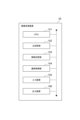
まず、図1~4を用いて、本開示の実施形態に係る瞳孔検出装置1の構成を説明する。瞳孔検出装置1は、対象者Aの眼を撮像することで対象者Aの瞳孔の位置を検出するコンピュータシステムである。対象者とは、瞳孔の位置を検出する対象となる人であり、被験者ともいうことができる。瞳孔検出装置1の利用目的は何ら限定されず、例えば、よそ見運転の検出、運転者のサイドミラーやルームミラーの安全確認動作の確認、運転者の眠気の検出、商品の興味の度合いの調査、アミューズメント装置等に利用されるコンピュータへのデータ入力、乳幼児の自閉症診断等の診断用装置などに瞳孔検出装置1を利用することができる。
First, the configuration of a
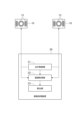
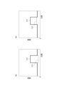
図1に模式的に示すように、瞳孔検出装置1は、ステレオカメラとして機能する一対のカメラ(第1のカメラおよび第2のカメラ)10と画像処理装置20とを備える。以下では、必要に応じて、一対のカメラ10を、対象者Aの左側にある左カメラ10Lと、対象者Aの右側にある右カメラ10Rとに区別する。本実施形態では、瞳孔検出装置1は、対象者Aが見る対象であるディスプレイ装置30をさらに備えるが、瞳孔検出装置1の利用目的は上記のように限定されないので、対象者Aの視線の先にある物はディスプレイ装置30に限定されず、例えば自動車のフロントガラスでもあり得る。したがって、ディスプレイ装置30は瞳孔検出装置1における必須の要素ではない。それぞれのカメラ10は画像処理装置20と無線または有線により接続され、カメラ10と画像処理装置20との間で各種のデータまたは命令が送受信される。各カメラ10に対しては予めカメラ較正が行われる。
As shown in FIG. 1, the
カメラ10は対象者Aの瞳孔およびその周辺を含む眼を撮影するために用いられる。一対のカメラ10は水平方向に沿って所定の間隔をおいて配され、かつ、対象者Aが眼鏡をかけているときの顔画像における反射光の写り込みを防止する目的で対象者Aの顔より低い位置に設けられる。水平方向に対するカメラ10の仰角は、瞳孔の確実な検出と対象者Aの視野範囲の妨げの回避との双方を考慮して、例えば20~35度の範囲に設定される。個々のカメラ10に対しては予めカメラ較正が行われる。
The
本実施形態では、カメラ10は、それぞれ、所定の時間間隔(例えば、120fpsの時間間隔)で撮像可能な撮像装置である。カメラ10は、画像処理装置20からの命令に応じて対象者Aを撮像し、画像データを画像処理装置20に出力する。
In this embodiment, the
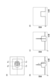
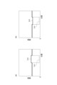
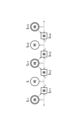
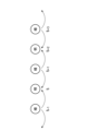
カメラ10のレンズ部分を図2に模式的に示す。この図に示すように、カメラ10では、対物レンズ11が円形状の開口部12に収容され、開口部12の外側に光源13が取り付けられている。光源13は、対象者Aの眼に向けて照明光を照射するための機器であり、複数の発光素子13a(第1の光源)と複数の発光素子13b(第2の光源)とから成る。発光素子13aは、出力光の中心波長が850nmの半導体発光素子(LED)であり、開口部12の縁に沿って等間隔でリング状に配される。発光素子13bは、出力光の中心波長が940nmの半導体発光素子であり、発光素子13aの外側の左右に上下方向に並んで配される。カメラ10の光軸から発光素子13bまでの距離は、該光軸から発光素子13aまでの距離よりも大きい。それぞれの発光素子13a,13bは、カメラ10の光軸に沿って照明光を出射するように設けられる。なお、光源13の配置は図2に示す構成に限定されず、カメラ10をピンホールモデルとみなすことができれば他の配置であってもよい。発光素子13a,13bは、それぞれ、画像処理装置20からの命令に応じた別々のタイミング及び期間で照明光を出射する。なお、発光素子13a,13bの出射する照明光の強度は、対象者Aに照射された際に瞳孔以外の背景が同じ明るさとなるように予めそれぞれの強度が設定される。
The lens part of the
光源13を構成する発光素子(第1の光源)13aは、明瞳孔画像を得るための照明光(第1の照明光)を、対象者Aの顔に向けて照射するための光源である。明瞳孔画像とは、後述の暗瞳孔画像と比較して対象者Aの瞳孔が相対的に明るく写った画像をいう。また、発光素子13aは、暗瞳孔画像の取得時に、眼鏡反射を生じさせて差分画像において眼鏡反射を相殺させるための光源としても共用される。
The light-emitting element (first light source) 13a constituting the
光源13を構成する発光素子(第2の光源)13bは、暗瞳孔画像を得るための照明光(第2の照明光)を、対象者Aの顔に向けて照射するための光源である。暗瞳孔画像とは、前述の明瞳孔画像と比較して対象者Aの瞳孔が相対的に暗く映った画像をいう。この発光素子13bは、明瞳孔画像及び暗瞳孔画像の取得時において角膜反射を強調して生じさせるための光源としても共用される。
The light-emitting element (second light source) 13b constituting the
画像処理装置20は、カメラ10及び光源13の制御と、対象者Aの瞳孔位置および視線方向の検出とを実行するコンピュータである。画像処理装置20は、据置型または携帯型のパーソナルコンピュータ(PC)により構築されてもよいし、ワークステーションにより構築されてもよいし、他の種類のコンピュータにより構築されてもよい。あるいは、画像処理装置20は複数台の任意の種類のコンピュータを組み合わせて構築されてもよい。複数台のコンピュータを用いる場合には、これらのコンピュータはインターネットやイントラネットなどの通信ネットワークを介して接続される。
The
画像処理装置20の一般的なハードウェア構成を図3に示す。画像処理装置20は、オペレーティングシステムやアプリケーション・プログラムなどを実行するCPU(プロセッサ)101と、ROMおよびRAMで構成される主記憶部102と、ハードディスクやフラッシュメモリなどで構成される補助記憶部103と、ネットワークカードあるいは無線通信モジュールで構成される通信制御部104と、キーボードやマウスなどの入力装置105と、ディスプレイやプリンタなどの出力装置106とを備える。
The general hardware configuration of the
後述する画像処理装置20の各機能要素は、CPU101または主記憶部102の上に所定のソフトウェアを読み込ませ、CPU101の制御の下で通信制御部104や入力装置105、出力装置106などを動作させ、主記憶部102または補助記憶部103におけるデータの読み出しおよび書き込みを行うことで実現される。処理に必要なデータやデータベースは主記憶部102または補助記憶部103内に格納される。
Each functional element of the
図4に示すように、画像処理装置20は機能的構成要素として点灯制御部21、画像取得部22、及び算出部23を備える。点灯制御部21は、光源13の点灯タイミング及び点灯期間を制御する。画像取得部22は、カメラ10の撮影タイミングを光源13の点灯タイミングに同期して制御することで、カメラ10から画像データ(眼画像のデータ)を取得する機能要素である。算出部23は、画像データを基に、対象者Aの瞳孔の三次元位置および対象者Aの視線方向として視線ベクトルを検出する機能要素である。視線とは、対象者Aの瞳孔中心と該対象者Aの注視点(対象者が見ている点)とを結ぶ線である。なお、「視線」という用語は、起点、終点、および方向の意味(概念)を含む。また、「視線ベクトル」とは、対象者の視線の方向をベクトルで表したもので、「視線方向」を表す一形態である。画像処理装置20の検出結果の瞳孔位置及び視線方向の出力先は何ら限定されない。例えば、画像処理装置20は判定結果を画像、図形、またはテキストでモニタに表示してもよいし、メモリやデータベースなどの記憶装置に格納してもよいし、通信ネットワーク経由で他のコンピュータシステムに送信してもよい。
As shown in FIG. 4, the
画像取得部22は、カメラ10の撮影タイミングを制御する機能要素である。具体的には、カメラ10を所定のフレームレート(例えば、120fps)及び所定の露光時間で繰り返し撮像し、交互に明瞳孔画像及び暗瞳孔画像を取得するように制御する。
The
点灯制御部21は、カメラ10の撮影タイミングに同期させて、発光素子13a,13bの点灯タイミング及びカメラ10の露光期間内の発光量を制御する機能要素である。本実施形態では、点灯制御部21は、発光素子13a,13bの発光量をそれぞれの点灯期間を設定することによって制御している。具体的には、点灯制御部21は、明瞳孔画像の撮像タイミングに同期した発光素子13aの比較的強い(比較的長い点灯期間での)点灯と、暗瞳孔画像の撮影タイミングに同期した発光素子13bの比較的強い(比較的長い点灯期間での)点灯とを交互に繰り返すように、発光素子13a,13bを点灯させる。このとき、点灯制御部21は、明瞳孔画像の撮影タイミングでは、角膜反射像を強調させるために、発光素子13bを比較的弱い強度で(比較的短い点灯期間で)点灯させるように制御し、暗瞳孔画像の撮影タイミングでは、眼鏡反射を生じさせて後述する差分画像において眼鏡反射を相殺させるために、発光素子13aを比較的弱い強度で(比較的短い点灯期間で)点灯させるように制御する。
The
上記画像取得部22及び上記点灯制御部21の機能により、主に発光素子13aから対象者Aの眼球に照明光が出射されるタイミングでカメラ10によって瞳孔が撮像されると明瞳孔画像が取得され、主に発光素子13bから照明光が出射されるタイミングでカメラ10によって瞳孔が撮像されると暗瞳孔画像が取得される。これは、次のような性質によるものである。つまり、対象者Aの眼球への照明光がカメラ10の光軸から相対的に離れた位置から入射した場合には、眼球の瞳孔から入射し、眼球内部で反射されて再び瞳孔を通過した照明光がカメラ10に届きにくいため、瞳孔が相対的に暗く映るという性質である。逆に、対象者Aの眼球への照明光がカメラ10の光軸に相対的に近い位置から入射した場合には、眼球の瞳孔から入射し、眼球内部で反射されて再び瞳孔を通過した照明光がカメラ10に届きやすいため、瞳孔が相対的に明るく映るという性質である。
Due to the functions of the
以下、算出部23による、対象者Aの瞳孔の三次元位置および対象者Aの視線方向の検出機能の詳細について説明する。
The following describes in detail the function of the
算出部23は、所定の時間間隔(例えば、120fpsに対応する時間間隔)で交互に取得された明瞳孔画像と暗瞳孔画像との2つの画像を用いて、明瞳孔画像のウィンドウ内の各画素の輝度から暗瞳孔画像のウィンドウ内の各画素の輝度を差し引いて差分を求めることにより差分画像を連続して取得する。このとき、明瞳孔画像と暗瞳孔画像を取得するタイミングには時間差があること、及び対象者Aがカメラ10に対して移動することを考慮して、算出部23は、特許第4452836号に記載の手法と同様の手法を用いて、明瞳孔画像及び暗瞳孔画像上において角膜反射像の位置を検出し、角膜反射像の位置が一致するように暗瞳孔画像の画像上のウィンドウの位置を明瞳孔画像に対して補正する。画像上の角膜反射像の位置は、前のフレームから得られた瞳孔輝度よりも高い角膜反射用閾値で2値化し、ラベリング処理を行い、最も角膜反射として大きさと形状を有する画素群を選択し、その画素群から、角膜反射像の中心を輝度も考慮した重心として求めることにより、検出される。一方で、算出部23は、明瞳孔画像及び暗瞳孔画像上において角膜反射像の位置を検出し、角膜反射像の位置が一致するように明瞳孔画像の画像上のウィンドウの位置を暗瞳孔画像に対して補正してもよい。このような機能により、算出部23は、上記の所定の時間間隔(例えば、120fpsに対応する時間間隔)で、差分画像を連続して取得することができる。図5は、算出部23による差分画像の算出機能を説明する概念図である。すなわち、明瞳孔画像及び暗瞳孔画像の所定の時間間隔の取得タイミングをti-1,ti,ti+1,…(iは任意の自然数)とすると、算出部23は、時刻tiにて取得される明瞳孔画像と時刻ti+1にて取得される暗瞳孔画像を基にした差分画像を、その後の演算時刻(例えば、ti+2)において取得し、次に、時刻ti+1にて取得される暗瞳孔画像と時刻ti+2にて取得される明瞳孔画像を基にした差分画像を、その後の演算時刻(例えば、ti+3)において取得する。
The
また、算出部23は、時間的に連続して取得した2個の差分画像を均等に演算する。すなわち、算出部23は、2個の差分画像の各画素の画素値を乗算することにより乗算画像を生成する。そして、算出部23は、時間的に連続する2個の差分画像を、1個ずつ時間的に後ろにずらして選択して乗算画像を生成することにより、上記の所定の時間間隔(例えば、120fpsに対応する時間間隔)での眼部の画像が反映された乗算画像を連続して生成する。例えば、算出部23は、演算時刻ti+1にて取得される差分画像と演算時刻ti+2にて取得される差分画像とを用いて、それらの画像が反映された乗算画像を、その後の演算時刻ti+3にて取得し、その後連続して演算時刻ti+4,ti+5,…にて乗算画像を取得する。
The
上記のように取得された乗算画像においては、瞳孔部における画素値が比較的大きな値を持ち、それ以外の部分が乗算画像の元になった差分画像に比較してより零値に近くなり、瞳孔部がより強調された画像となっている。このような性質を利用し、算出部23は、連続して取得した乗算画像を対象にして、対象者Aの瞳孔像の画像上の位置(以下、二次元位置ともいう。)を検出する。すなわち、算出部23は、乗算画像を瞳孔用閾値を基準に2値化し、孤立点除去、モルフォロジー処理によるノイズ除去、ラベリングを行う。そして、算出部23は、最も瞳孔らしい形状を有する画素群を、瞳孔として検出する。このとき、瞳孔がまぶたやまつ毛で隠れた場合にも、まぶたやまつ毛と瞳孔との境界を偽の瞳孔輪郭として排除し、真の瞳孔輪郭のみを楕円フィッティングして、真の瞳孔輪郭の乗算画像上の位置を検出し、楕円フィッティングで求まる楕円の式から瞳孔像の中心位置を算出する。このとき、算出部23は、演算対象の乗算画像の画素値のビット数を削減するために、乗算画像の画素値を所定値(例えば、画素値が8ビットで表現されている場合は2の8乗の値)で割ってから瞳孔像の二次元位置を検出してもよい。
In the multiplied image obtained as described above, the pixel values in the pupil area are relatively large, and the other areas are closer to zero compared to the difference image that was the basis of the multiplied image, resulting in an image in which the pupil area is more emphasized. Using this property, the
さらに、算出部23は、一対のカメラ10ごとに、同一の演算時間において取得された乗算画像を基に検出された瞳孔像の二次元位置と、その乗算画像の元となった3つの画像のうちの中間の暗瞳孔画像あるいは明瞳孔画像を対象に検出された角膜反射像の位置とを、連続して取得する。例えば、上記の演算時刻ti+3において取得された乗算画像に対しては、その乗算画像の元となった2つの差分画像の共通の演算元である、時刻tiの明瞳孔画像における角膜反射像の位置が対応する。また、上記の演算時刻ti+4において取得された乗算画像に対しては、その乗算画像の元となった2つの差分画像の共通の演算元である、時刻ti+1の暗瞳孔画像における角膜反射像の位置が対応する(図5)。そして、算出部23は、一対のカメラ10に対応して得られた瞳孔像の二次元位置を用いて、対象者Aの瞳孔の三次元位置を算出する。さらに、算出部23は、算出した瞳孔の三次元位置、一対のカメラ10ごとに得られた瞳孔像の二次元位置及び角膜反射像の位置とを用いて対象者Aの視線ベクトルおよび注視点を、所定の時間間隔で連続して検出する。上記の瞳孔の三次元位置の算出手法、視線ベクトルおよび注視点の算出手法は、本発明者らによって開発された手法(国際公開WO2012/020760号公報参照)を採用することができる。
Furthermore, the
ここで、上記説明では、差分画像の演算および乗算画像の演算が1フレームに相当する時間を要するという前提で差分画像及び乗算画像の演算時刻を記載している。一方で、これらの差分及び乗算の両方に要する時間の合計が十分短くて1フレームに対応する時間より小さい時間Δtである場合は、乗算画像の演算時刻を前倒しの時刻で得るように動作してもよい。例えば、図5に示す演算時刻ti+3で取得する乗算画像は、時刻ti+1に対して「Δt」の時間遅れで、言い換えれば、時刻tiに対して「1フレームの時間+Δt」の時間遅れで取得することができる。 Here, in the above description, the calculation times of the difference image and the multiplied image are described on the assumption that the calculation of the difference image and the calculation of the multiplied image require a time equivalent to one frame. On the other hand, if the total time required for both the difference and the multiplication is sufficiently short and is a time Δt that is shorter than the time corresponding to one frame, the calculation time of the multiplied image may be operated to be obtained at an earlier time. For example, the multiplied image obtained at the calculation time t i+3 shown in FIG. 5 can be obtained with a time delay of "Δt" from the time t i+1 , in other words, with a time delay of "the time of one frame + Δt" from the time t i .
以上説明した瞳孔検出装置1の作用効果について説明する。
The effects of the
瞳孔検出装置1によれば、カメラ10の開口部12の外側に配置された発光素子13a,13bが所定時間間隔で交互に点灯され、これらの点灯タイミングに合わせてカメラ10で眼画像が取得されることにより、瞳孔が相対的に明るく写った明瞳孔画像と瞳孔が相対的に暗く写った暗瞳孔画像とが交互に得られ、明瞳孔画像と暗瞳孔画像との画像ペアの差分から差分画像が連続して取得される。さらに、連続して取得された2個の差分画像を均等に演算することによって対象者Aの瞳孔位置が検出される。このように、連続する2個の差分画像を均等に演算することによって、周囲が明るい環境下であっても、周囲が暗い環境下であっても、連続して取得する差分画像において現れる瞳孔の位置を所定時間間隔のタイミングの位置に設定することができる。その結果、連続して取得する差分画像を基に、瞳孔の位置の変化を安定して検出することができる。特に、本実施形態は、比較的フレームレートの高い(通常の60fpsよりも高い)カメラを用いる場合に有効である。さらに、コストあるいは設置場所の広さの制限等の理由から、発光素子の数あるいは装置の設置面積を削減したい場合にも有効である。
According to the
また、本実施形態の算出部23は、明瞳孔画像及び暗瞳孔画像における角膜反射像の位置を検出し、交互に取得した明瞳孔画像及び暗瞳孔画像を対象に差分画像を取得する際には、角膜反射像の位置が一致するように画像位置を補正している。このような構成の場合、対象者Aの顔が動いた場合であっても、差分画像において瞳孔像を際立たせることができ、瞳孔位置の検出精度が向上する。その結果、連続して取得する差分画像を基に、瞳孔の位置の変化をさらに安定して検出することができる。
In addition, the
なお、本実施形態の算出部23は、交互に取得した明瞳孔画像及び暗瞳孔画像を対象に差分画像を取得する際には、角膜反射像の位置が一致するように暗瞳孔画像の位置を明瞳孔画像に対して補正するか、あるいは、角膜反射像の位置が一致するように明瞳孔画像の位置を暗瞳孔画像に対して補正している。こうすれば、画像位置を補正した場合に、周囲が明るい環境下であっても、周囲が暗い環境下であっても、連続して取得する差分画像において現れる瞳孔の位置を所定時間間隔のタイミングの位置に設定することができる。その結果、連続して取得する差分画像を基に、瞳孔の位置の変化をより安定して検出することができる。
When the
また、本実施形態の算出部23は、乗算画像を対象に検出した瞳孔の二次元位置、および、明瞳孔画像あるいは暗瞳孔画像を対象に検出した角膜反射像の位置を基に対象者Aの視線方向をさらに検出している。この場合には、連続して取得する差分画像を基に、視線方向の変化を安定して検出することができる。
In addition, the
上記のような瞳孔検出装置1による処理イメージを具体的に説明する。
The processing image of the
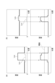
図6には、瞳孔検出装置1によって取得される明瞳孔画像及び暗瞳孔画像のイメージを示しており、(a)部には明瞳孔画像及び暗瞳孔画像の二次元分布のイメージを示し、(b)部には位置補正処理前の明瞳孔画像及び暗瞳孔画像の一次元分布のイメージを示し、(c)部には位置補正処理後の明瞳孔画像及び暗瞳孔画像の一次元分布のイメージを示し、(d)部には差分画像の一次元分布のイメージを示す。図6の(b)部~(d)部には、角膜反射像の中心に沿った直線上における画素値(輝度)の一次元分布を示し、簡略化のため瞳孔部以外の虹彩部分等の画素値が一定に表現されている(以下の各図においても同様)。
Figure 6 shows images of the bright pupil image and dark pupil image acquired by the
図6の(a)部に示すように、瞳孔検出装置1によって取得される明瞳孔画像上で比較的輝度が高い瞳孔部PBが現れ、瞳孔検出装置1によって取得される暗瞳孔画像上で比較的輝度が低い瞳孔部PDが現れ、それぞれの画像上には輝度が瞳孔部PB,PDよりも高い角膜反射像CB,CDが現れる。これらの明瞳孔画像及び暗瞳孔画像においては、発光素子13a,13bの設置位置の違いに起因して対象者Aの顔の輪郭部等において明暗差が生じたり、対象者Aの顔の動きにより顔の各部分に明暗差が生じる傾向にある。そこで、瞳孔検出装置1の算出部23は、差分画像において瞳孔の誤検出を防止するために、明瞳孔画像及び暗瞳孔画像において各瞳孔部を含むようなウィンドウを設定し、そのウィンドウ内の画像を用いて差分画像を生成するようにしている。さらに、算出部23は、対象者Aの動きにより明瞳孔画像における瞳孔部PBと暗瞳孔画像の瞳孔部PDとの間で位置がずれた場合(図6の(b)部)、互いのウィンドウの位置を角膜反射像CB,CDが一致するように補正した後に(図6の(c)部)、互いのウィンドウの共通部分を差分することにより差分画像を生成することにより(図6の(c)部)、瞳孔の位置の検出精度を保つようにしている。
6A, a pupil area P B with a relatively high luminance appears in the bright pupil image acquired by
なお、明瞳孔画像における瞳孔部PBは、暗瞳孔画像の瞳孔部PDに比較して輝度が高いが、瞳孔検出装置1が太陽光などの近赤外線を含む光が照射する環境で使用される場合には、対象者Aの顔が明るくなるために輝度が周辺部に比較して低くなる場合がある。さらに、このように周辺部が明るくなる環境下では対象者Aの瞳孔が一般的に小さくなるため、瞳孔部PBの輝度が低くなりやすい。これは、対象者Aの瞳孔を通過して眼球内に入射する光量が減少するためであり、光源とカメラと対象者との位置関係、及び、対象者の視線方向の変化がなければ、瞳孔面積と瞳孔輝度との間には比例関係が成り立つためである。同様に、暗瞳孔画像あるいは差分画像における瞳孔部においても、瞳孔面積と瞳孔輝度との間には比例関係が成り立つ。
The pupil area P B in the bright pupil image has a higher luminance than the pupil area P D in the dark pupil image, but when the
ここで、対象者の瞳孔面積あるいは使用環境に応じた瞳孔検出装置1における差分画像を用いた瞳孔像の位置の検出状態の変化について説明する。
Here, we explain how the detection state of the pupil image position using the differential image in
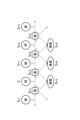
図7には、周囲が暗い環境下あるいは瞳孔面積が大きい場合における明瞳孔画像及び暗瞳孔画像の一次元分布を示す。図7の(a)部に示す状態では、明瞳孔画像における瞳孔部PBの輝度LPBが、周辺の虹彩等よりも明らかに高くなっており、暗瞳孔画像における瞳孔部PDの輝度LPDは、周辺の虹彩等より少し低くなっている。図7の(b)部に示す状態では、明瞳孔画像における瞳孔部PBの輝度LPBが、周辺の虹彩等よりも明らかに高くなっており、暗瞳孔画像における瞳孔部PDの輝度LPDは、周辺の虹彩等より少し高くなっている。これらの状態は、明瞳孔画像において瞳孔部が明るく光りやすい一方で、暗瞳孔画像においては瞳孔部が他の部分に対して輝度が同等で目立たない状態である(以下、このような状態を「明瞳孔優位」と呼ぶ。)。 7 shows one-dimensional distributions of bright and dark pupil images in a dark environment or when the pupil area is large. In the state shown in FIG. 7(a), the luminance LPB of the pupil area PB in the bright pupil image is obviously higher than the surrounding iris, etc., and the luminance LPD of the pupil area PD in the dark pupil image is slightly lower than the surrounding iris, etc. In the state shown in FIG. 7(b), the luminance LPB of the pupil area PB in the bright pupil image is obviously higher than the surrounding iris, etc., and the luminance LPD of the pupil area PD in the dark pupil image is slightly higher than the surrounding iris, etc. In these states, the pupil area tends to shine brightly in the bright pupil image, while in the dark pupil image, the pupil area has the same luminance as other areas and is not noticeable (hereinafter, such a state is called "bright pupil dominance").
図8には、周囲が明るい環境下あるいは瞳孔面積が小さい場合における明瞳孔画像及び暗瞳孔画像の一次元分布を示す。図8の(a)部に示す状態では、暗瞳孔画像における瞳孔部PDの輝度LPDが、周辺の虹彩等よりも明らかに低くなっており、明瞳孔画像における瞳孔部PBの輝度LPBは、周辺の虹彩等より少し高くなっている。図8の(b)部に示す状態では、暗瞳孔画像における瞳孔部PDの輝度LPDが、周辺の虹彩等よりも明らかに低くなっており、明瞳孔画像における瞳孔部PBの輝度LPBは、周辺の虹彩等より少し低くなっている。これらの状態は、暗瞳孔画像において瞳孔部が暗くなりやすい一方で、明瞳孔画像においては瞳孔部が他の部分に対して輝度が同等で目立たない状態である(以下、このような状態を「暗瞳孔優位」と呼ぶ。)。 Fig. 8 shows one-dimensional distributions of bright and dark pupil images in a bright environment or when the pupil area is small. In the state shown in Fig. 8(a), the luminance LPD of the pupil area PD in the dark pupil image is obviously lower than the surrounding iris, etc., and the luminance LPB of the pupil area PB in the bright pupil image is slightly higher than the surrounding iris, etc. In the state shown in Fig. 8(b), the luminance LPD of the pupil area PD in the dark pupil image is obviously lower than the surrounding iris, etc., and the luminance LPB of the pupil area PB in the bright pupil image is slightly lower than the surrounding iris, etc. In these states, the pupil area tends to be dark in the dark pupil image, while in the bright pupil image, the pupil area has the same luminance as other areas and is not noticeable (hereinafter, such a state is called "dark pupil dominance").
上記のような明瞳孔優位及び暗瞳孔優位の状態で瞳孔像が画像中で動いた場合を想定する。図9の(a)部及び(b)部には、それぞれ、明瞳孔優位及び暗瞳孔優位の場合の画像の一次元分布を示し、上側に明瞳孔画像及び暗瞳孔画像の一次元分布を示し、下側に差分画像の一次元分布を示している。 Let us consider a case where the pupil image moves within the image in the above-mentioned light pupil dominance and dark pupil dominance states. Parts (a) and (b) of Figure 9 show the one-dimensional distribution of images in the light pupil dominance and dark pupil dominance states, respectively, with the top showing the one-dimensional distribution of the light pupil image and the dark pupil image, and the bottom showing the one-dimensional distribution of the difference image.
図9の(a)部に示すように、明瞳孔優位の場合は、差分画像において直前に得られた差分画像の瞳孔部の輝度の平均値の50%を閾値として設定した場合、それによって検出される瞳孔像のエッジは元の明瞳孔画像における瞳孔部のエッジと一致する。一方、図9の(b)部に示すように、暗瞳孔優位の場合は、同様な閾値によって検出される瞳孔像のエッジは元の暗瞳孔画像における瞳孔部のエッジと一致する。このことから、差分画像を基に瞳孔の二次元位置を検出しようとする場合、明瞳孔優位の場合は明瞳孔画像の瞳孔が検出され、暗瞳孔優位の場合には暗瞳孔画像の瞳孔が検出されることが分かる。 As shown in part (a) of Figure 9, in the case of light pupil dominance, when a threshold value is set to 50% of the average brightness of the pupil area in the difference image obtained immediately before in the difference image, the edge of the pupil image detected thereby matches the edge of the pupil area in the original bright pupil image. On the other hand, as shown in part (b) of Figure 9, in the case of dark pupil dominance, the edge of the pupil image detected using a similar threshold value matches the edge of the pupil area in the original dark pupil image. From this, it can be seen that when attempting to detect the two-dimensional position of the pupil based on the difference image, in the case of light pupil dominance, the pupil in the bright pupil image is detected, and in the case of dark pupil dominance, the pupil in the dark pupil image is detected.
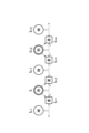
図10に示すように、時刻ti-1,ti,ti+1,…において、暗瞳孔画像、明瞳孔画像、暗瞳孔画像、…と順に取得された場合を仮定する。算出部23によって連続した時刻に取得された明瞳孔画像及び暗瞳孔画像を基に、明瞳孔画像から暗瞳孔画像を差し引いて差分画像が取得される。例えば、時刻tiに得られた明瞳孔画像から時刻ti-1で得られた暗瞳孔画像が差し引かれることにより、演算時刻ti+1に差分画像が得られる。その次に、既に時刻tiで取得された明瞳孔画像から時刻ti+1で取得される暗瞳孔画像が差し引かれることにより、演算時刻ti+2に差分画像が得られる。ここで、明瞳孔優位の状態の場合には、互いに位置ずれが生じている明瞳孔画像及び暗瞳孔画像から差分画像を生成した際には明瞳孔画像における瞳孔位置が検出されることになるため、上記の2枚の差分画像において検出される瞳孔の二次元位置は、ともに時刻tiでの明瞳孔画像における瞳孔の二次元位置となる。つまり、演算時刻ti+1,ti+2において同じ位置が続けて2回検出される。同様に、演算時刻ti+3,ti+4において、時刻ti+2での明瞳孔画像における瞳孔位置が続けて2回検出される。
10, it is assumed that a dark pupil image, a bright pupil image, a dark pupil image, ... are acquired in this order at times t i-1 , t i , t i+1 , .... Based on the bright pupil image and the dark pupil image acquired at successive times by the
また、図11に示すように、暗瞳孔優位の状態の場合には、互いに位置ずれが生じている明瞳孔画像及び暗瞳孔画像から差分画像を生成した際には暗瞳孔画像における瞳孔位置が検出されることになるため、演算時刻ti+2,ti+3で取得される2枚の差分画像において検出される瞳孔の二次元位置は、ともに時刻ti+1での暗瞳孔画像における瞳孔の二次元位置となる。つまり、演算時刻ti+2,ti+3において同じ位置が続けて2回検出される。 11 , in the case of a dark pupil dominant state, when a difference image is generated from a bright pupil image and a dark pupil image which are misaligned with each other, the pupil position in the dark pupil image is detected, so the two-dimensional positions of the pupil detected in the two difference images acquired at calculation times t i+2 and t i+3 are both the two-dimensional position of the pupil in the dark pupil image at time t i+1 . In other words, the same position is detected twice in a row at calculation times t i+2 and t i+3 .
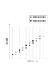
このように、明瞳孔画像と暗瞳孔画像との間の位置補正を実行しない場合は、明瞳孔優位の場合は、時刻tiと時刻ti+2の瞳孔の二次元位置が得られ、暗瞳孔優位の場合は、時刻ti+1と時刻ti+3の瞳孔の二次元位置が得られることがわかり、明瞳孔優位の状態と暗瞳孔優位の状態とでは、瞳孔の二次元位置が得られる時刻が異なってくる。図12には、瞳孔位置が一方向に等速で変化する場合に、算出部23によって検出される瞳孔位置の画像フレーム毎の変化を示している。このように、明瞳孔優位であっても暗瞳孔優位であっても、2枚の画像フレームで連続して同じ位置が検出され、明瞳孔優位の状態と暗瞳孔優位の状態とでは、同じ位置が連続して得られるタイミングが1フレームずれてしまう。つまり、別の観点から考えると、カメラ10のフレームレートの半分の頻度でしか瞳孔位置を検出できないこととなる。瞳孔位置の検出頻度が低いと次の画像フレームにおける瞳孔位置の予測の精度が低くなり、差分画像の生成対象となるウィンドウの位置を正確に設定することが困難となる。その結果、ウィンドウサイズを大きくする必要があり、背景ノイズを拾いやすくなって瞳孔検出のロバスト性が低下する。
In this way, when the position correction between the bright pupil image and the dark pupil image is not performed, the two-dimensional position of the pupil at time t i and time t i+2 is obtained in the case of bright pupil dominance, and the two-dimensional position of the pupil at time t i+1 and time t i+3 is obtained in the case of dark pupil dominance, and the time at which the two-dimensional position of the pupil is obtained differs between the bright pupil dominance state and the dark pupil dominance state. Figure 12 shows the change in the pupil position detected by the
ここで注意すべき点は、差分画像によって瞳孔が検出されて瞳孔領域が明確になる前においては、その瞳孔の位置が明瞳孔画像における瞳孔像のものなのか暗瞳孔画像における瞳孔像のものなのかが不明という点である。つまり、角膜反射像に基づく位置補正を行って差分演算および二値化演算を行って瞳孔領位置が明確になって初めて、明瞳孔優位の状態か暗瞳孔優位の状態かが明らかになる。そのため、差分画像に基づく瞳孔の二次元位置の検出時にその瞳孔位置の時刻を解析することはその処理が煩雑となる。 It should be noted here that before the pupil is detected by the difference image and the pupil area is clarified, it is unclear whether the position of the pupil is that of the pupil image in the bright pupil image or that of the pupil image in the dark pupil image. In other words, it is only once the pupil area position is clarified by performing position correction based on the corneal reflection image, subtraction calculations, and binarization calculations, that it becomes clear whether the state is bright pupil dominant or dark pupil dominant. For this reason, analyzing the time of the pupil position when detecting the two-dimensional position of the pupil based on the difference image is a cumbersome process.
これに対して、本実施形態では、連続して取得された2個の差分画像を均等に演算することによって対象者Aの瞳孔位置が検出されるため、煩雑な処理は不要である。特に、本実施形態では、瞳孔が画像中をおおよそ等速で移動するのであれば、明瞳孔優位あるいは暗瞳孔優位のいずれの場合であっても、連続する差分画像において瞳孔位置の誤差の方向が逆となっている。このような性質を考慮して乗算画像を利用して瞳孔位置を検出することによって、2枚の差分画像中の瞳孔位置の誤差が相殺されることになり、瞳孔位置の検出精度が向上する。 In contrast, in this embodiment, the pupil position of subject A is detected by equally calculating two difference images acquired in succession, so no complicated processing is required. In particular, in this embodiment, if the pupil moves at approximately the same speed in the image, the direction of the pupil position error will be opposite in successive difference images regardless of whether the pupil is light pupil dominant or dark pupil dominant. By detecting the pupil position using the multiplied image taking this property into account, the error in the pupil position in the two difference images is offset, improving the accuracy of pupil position detection.
また、本実施形態の瞳孔検出装置1によれば、明瞳孔優位か暗瞳孔優位かが不明の状況で対象者Aの頭部が動く場合であっても、瞳孔位置の検出精度を向上させるとともに、瞳孔形状までも正確に検出することが可能である。図13に示すように、本実施形態にかかる算出部23により、時刻ti-1の暗瞳孔画像と時刻tiの明瞳孔画像との間の差分画像を演算時刻ti+1で生成する際には、時刻ti-1の暗瞳孔画像の位置が時刻tiの明瞳孔画像に対して補正される。このとき、明瞳孔優位の状態であると、演算時刻ti+1の差分画像で得られる瞳孔位置は時刻tiにおける瞳孔位置となる。その後、演算時刻ti+2の差分画像で得られる瞳孔位置も時刻tiにおける瞳孔位置となる。また、暗瞳孔優位の状態である場合は、演算時刻ti+1の差分画像で得られる瞳孔位置は時刻ti-1における瞳孔位置を位置補正したものなる。その後、演算時刻ti+2の差分画像で得られる瞳孔位置は時刻ti+1における瞳孔位置を位置補正したものとなる。そのため、連続した演算時刻で得られた差分画像を基にした乗算画像を用いることにより、瞳孔位置の変化を精度よく検出できる。
Furthermore, according to the
一方で、明瞳孔画像と暗瞳孔画像との間の位置補正としては、直前のフレームの画像を直後のフレームの画像に対して補正する処理も考えられる。この場合、明瞳孔優位の状態であると、演算時刻ti+1の差分画像で得られる瞳孔位置は時刻tiにおける瞳孔位置となる。その後、演算時刻ti+2の差分画像で得られる瞳孔位置は時刻tiにおける瞳孔位置を位置補正したものとなる。そのため、演算時刻ti+2においては時刻tiの瞳孔位置を時刻ti+1の瞳孔位置に誤って検出することになり、連続した演算時刻で得られた差分画像を基にした乗算画像を用いても、瞳孔位置の検出精度を高めることはできない。この場合、明瞳孔優位であることが予めわかっていれば、演算時刻ti+2において得られる瞳孔位置を時刻tiのものと認識すれば問題ないが、既に述べたように、そのように認識することは困難である。暗瞳孔優位の状態の場合は、演算時刻ti+1の差分画像で得られる瞳孔位置は時刻ti-1における瞳孔位置が位置補正されたものとなる。その後、演算時刻ti+2の差分画像で得られる瞳孔位置は時刻ti+1における瞳孔位置となる。そのため、演算時刻ti+1においては時刻ti-1の瞳孔位置を時刻tiの瞳孔位置に誤って検出することになり、連続した演算時刻で得られた差分画像を基にした乗算画像を用いても、瞳孔位置の検出精度を高めることはできない。この場合も、暗瞳孔優位であることは不明であるため、瞳孔位置の検出時刻を修正することは困難である。 On the other hand, as a position correction between the bright pupil image and the dark pupil image, a process of correcting the image of the immediately preceding frame with respect to the image of the immediately following frame can also be considered. In this case, in a state of bright pupil dominance, the pupil position obtained in the difference image at the calculation time t i+1 is the pupil position at time t i . Thereafter, the pupil position obtained in the difference image at the calculation time t i+2 is the pupil position at time t i that has been position-corrected. Therefore, at the calculation time t i+2 , the pupil position at time t i is erroneously detected as the pupil position at time t i+1 , and even if a multiplied image based on the difference images obtained at successive calculation times is used, the detection accuracy of the pupil position cannot be improved. In this case, if it is known in advance that the bright pupil is dominant, there is no problem if the pupil position obtained at the calculation time t i+2 is recognized as that at time t i , but as already mentioned, it is difficult to recognize it in this way. In the case of a dark pupil dominant state, the pupil position obtained from the difference image at calculation time t i+1 is the pupil position at time t i-1 that has been position-corrected. Thereafter, the pupil position obtained from the difference image at calculation time t i+2 is the pupil position at time t i+1 . Therefore, at calculation time t i+1 , the pupil position at time t i-1 will be erroneously detected as the pupil position at time t i erroneously, and even if a multiplied image based on difference images obtained at successive calculation times is used, the detection accuracy of the pupil position cannot be improved. In this case, too, it is unclear that the pupil is dark pupil dominant, so it is difficult to correct the detection time of the pupil position.
図14の(a)部には差分画像の輝度分布を示し、図14の(b)部には連続した差分画像を基にした乗算画像の輝度分布を示し、図15には同一の差分画像を基にした乗算画像の輝度分布を示している。それぞれの図において、上側に各画像の表示例を示し、下側に各画像の一次元輝度分布を示す。このように、図14の(a)部に示される差分画像においては背景と瞳孔との輝度にあまり差が生じていないが、図14の(b)部に示されるように、連続した差分画像を基にした乗算画像においては、左右の瞳孔輝度が高くなっているとともに瞳孔部以外の背景部分のノイズが小さくなっており、乗算画像を用いることで瞳孔位置が検出しやすくなることが分かる。また、図15に示されるように、同一の差分画像を基にした乗算画像においては、瞳孔以外の背景部分に高輝度点が多く見られ、ノイズが強調されている。これは、画素間の画素値の大小関係は二乗しても変化しないためである。従って、同一の差分画像を基にした乗算画像を用いると、瞳孔を誤検出する可能性がある。しかも、画素値は離散的であるので、256諧調の画素値の差分画像を二乗した画像も256諧調であり、瞳孔位置の検出のための閾値を設定する際の容易さには変化がない。これに対して、連続する異なる差分画像を乗算する場合には、元の差分画像の一方が異なっている。例えば、明瞳孔画像は共通であるが暗瞳孔画像は異なっている。通常、これらの2つの暗瞳孔画像は異なったノイズを含む。そのため、乗算画像において、ランダムノイズを含むノイズ、および頭部が動くことによる画像の変化による差分画像上の輝度変化が相殺されて、瞳孔以外の部分の輝度値が零に近づくことになる。また、乗算画像においては、一方の差分画像上の瞳孔部の画素の輝度が低くなっても、他方の差分画像上の同一画素の輝度がそれを補うことになる。上述した結果から、本実施形態のように時間的に連続する差分画像を基にした乗算画像を用いることが、瞳孔輝度を高くして瞳孔位置が検出しやすくなること、及びノイズの影響を除去することに関して有効であることが示された。 Part (a) of FIG. 14 shows the luminance distribution of the difference image, part (b) of FIG. 14 shows the luminance distribution of the multiplied image based on consecutive difference images, and part (b) of FIG. 15 shows the luminance distribution of the multiplied image based on the same difference image. In each figure, the upper part shows an example of the display of each image, and the lower part shows the one-dimensional luminance distribution of each image. Thus, in the difference image shown in part (a) of FIG. 14, there is not much difference in luminance between the background and the pupil, but as shown in part (b) of FIG. 14, in the multiplied image based on consecutive difference images, the luminance of the left and right pupils is high and the noise in the background part other than the pupil part is small, and it can be seen that the pupil position can be easily detected by using the multiplied image. Also, as shown in FIG. 15, in the multiplied image based on the same difference image, many high luminance points are seen in the background part other than the pupil, and the noise is emphasized. This is because the magnitude relationship between pixel values between pixels does not change even when squared. Therefore, if a multiplied image based on the same difference image is used, there is a possibility that the pupil will be erroneously detected. Moreover, since the pixel values are discrete, the image obtained by squaring the difference image of the pixel values of 256 gradations also has 256 gradations, and the ease of setting the threshold for detecting the pupil position remains unchanged. In contrast, when successive different difference images are multiplied, one of the original difference images is different. For example, the bright pupil image is common, but the dark pupil image is different. Usually, these two dark pupil images contain different noises. Therefore, in the multiplied image, noise including random noise and brightness changes in the difference image due to changes in the image caused by head movement are offset, and the brightness value of the part other than the pupil approaches zero. Also, in the multiplied image, even if the brightness of the pixel of the pupil part in one difference image becomes low, the brightness of the same pixel in the other difference image compensates for it. From the above results, it was shown that using a multiplied image based on temporally consecutive difference images as in this embodiment is effective in increasing the pupil brightness to make it easier to detect the pupil position, and in removing the influence of noise.
さらに、本実施形態の算出部23は、連続する差分画像を基に乗算画像を取得している。つまり、演算時刻ti+2,ti+4等の演算時刻が1フレームを超えて離れた差分画像を用いていない。演算時刻ti+2,ti+4で取得された2つの差分画像を基に乗算画像を生成する場合も、2つの差分画像の元となる明瞳孔画像と暗瞳孔画像とが両方とも違うので、乗算の効果は得られる。しかしながら、このような乗算画像では、明瞳孔優位あるいは暗瞳孔優位の状態における瞳孔位置のずれ量が相殺されない。本実施形態では、瞳孔が画像中をおおよそ等速で移動するのであれば、明瞳孔優位あるいは暗瞳孔優位のいずれの場合であっても、それぞれの差分画像におけるずれ方向が同一であるので2枚の差分画像中の瞳孔位置は一致することになり、乗算による効果が期待できる。
Furthermore, the
本発明は、上述した実施形態に限定されるものではない。上記実施形態の構成は様々変更されうる。 The present invention is not limited to the above-described embodiment. The configuration of the above embodiment may be modified in various ways.
上述した実施形態では、算出部23は、所定の時間間隔で取得された連続するN個(Nは2以上の偶数)の差分画像を基に乗算画像を生成し、その乗算画像を基に瞳孔の二次元位置および視線方向を検出してもよい。この場合も、瞳孔の位置の変化を安定して検出することができる。特に、乗算画像の生成元を偶数個の差分画像に設定することにより、連続する差分画像における瞳孔位置及び視線方向の誤差方向が逆方向であることに対してその誤差を確実に相殺することができる。また、解析が必要な瞳孔の位置変化の時間間隔に応じて、乗算画像の元となる差分画像の数を設定することで演算量を削減することができる。
In the above-described embodiment, the
また、上述した実施形態の算出部23は、明瞳孔画像と暗瞳孔画像との間で角膜反射像の位置を用いた位置補正を行っているが、特許第4452832号に記載の鼻孔に基づく位置補正を行ってもよいし、特許第5429885号、特許第6083761号、特許第6583734号、及び特許第6555707号に記載の三次元空間での瞳孔の位置を予測することによる位置補正を行ってもよい。
In addition, the
また、上記実施形態の変形例として、算出部23は、連続する差分画像を均等の演算結果に反映する際には、次のように処理してもよい。すなわち、算出部23は、連続して取得した2つの差分画像を対象に、上述した方法と同様にして2つの瞳孔の二次元位置の候補を検出し、2つの瞳孔位置の候補の平均値を演算結果として取得し、その演算結果を基に最終的な瞳孔の二次元位置を検出してもよい。このようにすれば、演算時刻ti+1,ti+2で得られる2つの差分画像によって検出される2つの瞳孔位置を平均化することにより、明瞳孔優位の場合であっても暗瞳孔優位の場合であっても、その結果得られる瞳孔位置を時刻tiにおける瞳孔位置に近い位置とすることができる。その結果、連続して取得する差分画像を基に、瞳孔位置の変化を安定して検出することができる。
As a modification of the above embodiment, the
また、上記実施形態の別の変形例として、算出部23は、連続する差分画像を基に検出した視線方向を平均化することにより、連続する差分画像を均等の演算結果に反映してもよい。すなわち、算出部23は、連続して取得した2つの差分画像を対象に、上述した実施形態と同様にして、それぞれの差分画像を基に瞳孔の二次元位置と角膜反射像の位置とを検出し、それらを用いて2つの視線方向の候補を検出し、2つの視線方向の候補の平均値を演算結果として取得し、その演算結果を基に最終的な視線方向を検出してもよい。
As another modification of the above embodiment, the
ただし、上記別の変形例においては、算出部23は、連続する差分画像を基に2つの視線方向の候補を検出する際には、連続する差分画像から検出した2つの瞳孔位置を平均化したものを用いてもよい。
However, in the above-mentioned other modified example, when detecting two candidate gaze directions based on successive difference images, the
視線方向の検出を精度よく実現するためには、瞳孔の位置と角膜反射の位置とは同じ時刻に検出されたものを用いる必要がある。視線は基本的に瞳孔中心と角膜反射点位置との相対関係から算出されるため、両者の検出時刻がずれていると、検出される視線に大きなばらつきが発生したり、頭部が一定方向に移動している場合にその方向に依存した視線のずれが生じる。例えば、明瞳孔優位の場合には、演算時刻ti+1,ti+2で得られる差分画像から検出されるのは、時刻tiの瞳孔の位置であり、角膜反射の位置も時刻tiでの明瞳孔画像上の位置であるため(図10)、問題は生じない。しかし、暗瞳孔優位の場合には、演算時刻ti+1,ti+2で得られる差分画像から検出されるのは、それぞれ時刻ti-1,ti+1の瞳孔の位置であり、角膜反射の位置は時刻tiでの明瞳孔画像上の位置であるため(図11)、別々の時刻に検出された瞳孔位置と角膜反射位置から視線方向を検出することになってしまう。その結果、視線検出結果にばらつきが生じてしまう。 In order to accurately detect the gaze direction, it is necessary to use the pupil position and the corneal reflection position detected at the same time. Since the gaze is basically calculated from the relative relationship between the pupil center and the corneal reflection point position, if the detection times of the two are shifted, the detected gaze will vary greatly, and if the head moves in a certain direction, the gaze will be shifted depending on the direction. For example, in the case of light pupil dominance, what is detected from the difference images obtained at the calculation times t i+1 and t i+2 is the pupil position at time t i , and the corneal reflection position is also the position on the bright pupil image at time t i (FIG. 10), so no problem occurs. However, in the case of dark pupil dominance, what is detected from the difference images obtained at the calculation times t i+1 and t i+2 is the pupil position at time t i-1 and t i+1 , respectively, and the corneal reflection position is the position on the bright pupil image at time t i (FIG. 11), so the gaze direction will be detected from the pupil position and the corneal reflection position detected at different times. As a result, the gaze detection results vary.
直前のフレームの画像位置をその直後のフレームの画像位置に対して補正する場合にも、検出される視線方向にずれが生じる。明瞳孔優位の場合には、時刻ti-1の暗瞳孔画像を時刻tiの明瞳孔画像に対して位置補正したときは問題ないが、時刻tiの明瞳孔画像をti+1の暗瞳孔画像に対して位置補正したときには視線方向がずれる(図10)。暗瞳孔優位の場合は、時刻tiの明瞳孔画像を時刻ti+1の暗瞳孔画像に対して位置補正したときは問題ないが、時刻ti-1の暗瞳孔画像をtiの明瞳孔画像に対して位置補正したときには視線方向がずれる(図11)。そのずれ量は、瞳孔の画像中での移動速度に依存し、移動速度が大きいときほどずれ量が大きくなる。 A deviation in the detected gaze direction also occurs when the image position of the immediately preceding frame is corrected relative to the image position of the immediately succeeding frame. In the case of light pupil dominance, there is no problem when the dark pupil image at time t i-1 is position-corrected relative to the bright pupil image at time t i , but the gaze direction is shifted when the bright pupil image at time t i is position-corrected relative to the dark pupil image at time t i+1 (FIG. 10). In the case of dark pupil dominance, there is no problem when the bright pupil image at time t i is position-corrected relative to the dark pupil image at time t i+1 , but the gaze direction is shifted when the dark pupil image at time t i-1 is position-corrected relative to the bright pupil image at time t i (FIG. 11). The amount of deviation depends on the moving speed of the pupil in the image, and the greater the moving speed, the greater the amount of deviation.
一方、上記変形例によれば、明瞳孔優位か暗瞳孔優位かが不明な場合に、頭部が動いても視線方向あるいは注視点を正確に追尾できる。瞳孔が画像中でほぼ等速で動いていると仮定すると、暗瞳孔優位の場合は、時刻ti-1の暗瞳孔画像を時刻tiの明瞳孔画像に対して位置補正して両画像から差分画像を生成するときと、時刻ti+1の暗瞳孔画像を時刻tiの明瞳孔画像に対して位置補正して両画像から差分画像を生成するときとでは、検出される視線方向のずれる方向が正反対となる。従って、連続して検出される視線方向はばらつきを有し、そのばらつき方向は正反対である。さらに、明瞳孔優位の場合は、時刻ti-1の暗瞳孔画像を時刻tiの明瞳孔画像に対して位置補正して両画像から差分画像を生成するときと、時刻ti+1の暗瞳孔画像を時刻tiの明瞳孔画像に対して位置補正して両画像から差分画像を生成するときとでは、検出される視線方向が正しいので、それらの検出結果を平均化した視線方向も正しい方向を示す。本変形例によれば、差分画像を用いて連続して検出される視線方向を平均化することにより本来の正しい視線方向を検出することができる。 On the other hand, according to the above modification, when it is unclear whether the pupil is light pupil dominant or dark pupil dominant, the gaze direction or gaze point can be accurately tracked even if the head moves. Assuming that the pupil moves at a substantially constant speed in the image, in the case of dark pupil dominance, the direction of deviation of the detected gaze direction is opposite when the dark pupil image at time t i-1 is position-corrected relative to the light pupil image at time t i to generate a difference image from both images, and when the dark pupil image at time t i+1 is position-corrected relative to the light pupil image at time t i to generate a difference image from both images. Therefore, the gaze directions detected successively have variations, and the directions of the variations are opposite. Furthermore, in the case of light pupil dominance, when a difference image is generated from the dark pupil image at time t i-1 by correcting the position of the dark pupil image at time t i with respect to the bright pupil image at time t i and when a difference image is generated from the dark pupil image at time t i+1 by correcting the position of the dark pupil image at time t i with respect to the bright pupil image at time t i , the gaze direction detected is correct, and therefore the gaze direction obtained by averaging these detection results also indicates the correct direction. According to this modification, the gaze directions detected consecutively using the difference image are averaged, making it possible to detect the original and correct gaze direction.
また、上記の2つの変形例においても、所定の時間間隔で取得された連続するN個(Nは2以上の偶数)の差分画像を基に演算結果を平均化して、平均化した演算結果を基に瞳孔の二次元位置および視線方向を検出してもよい。 In addition, in the two modified examples above, the calculation results may be averaged based on N consecutive difference images (N is an even number equal to or greater than 2) acquired at a predetermined time interval, and the two-dimensional position of the pupil and the gaze direction may be detected based on the averaged calculation results.
また、上記実施形態に係る算出部23は、交互に取得した明瞳孔画像及び暗瞳孔画像を基に差分画像を取得する際には、当該差分画像より先の演算時刻に連続して取得された2つの乗算画像を基に検出された2つの瞳孔の二次元位置の変化から、明瞳孔画像及び暗瞳孔画像に対してウィンドウを設定し、設定したウィンドウ間で差分画像を生成してもよい。例えば、算出部23は、時刻ti-1,ti,ti+1の3枚の眼部画像を基にした乗算画像から検出した瞳孔位置を、時刻tiの位置として検出し、時刻ti-2,ti-1,tiの3枚の眼部画像を基にした乗算画像から検出した瞳孔位置を、時刻ti-1の位置として検出する。算出部23は、これらの瞳孔位置から時刻ti+2における瞳孔の二次元位置を予測する。同様に、算出部23は、時刻ti+1における瞳孔の二次元位置を、時刻ti-2の瞳孔位置と時刻ti-1の瞳孔位置とから予測する。そして、算出部23は、予測した瞳孔位置を基に、差分画像を取得する際に、時刻ti+1における眼部画像上のウィンドウの位置、及び、時刻ti+2における眼部画像上のウィンドウの位置を設定することができる。このような変形例によれば、対象者Aの顔が動いた場合であっても、差分画像において瞳孔像を確実に捉えることができ、瞳孔位置を安定して検出することができる。加えて、ウィンドウを設定することで画像演算の範囲を限定できるので瞳孔検出の演算速度も向上させることができる。
Furthermore, when the
また、上記実施形態、上記変形例、及び上記別の変形例においては、明瞳孔画像と暗瞳孔画像を取得する時間間隔が1フレームに対応する間隔で一定でなく変化する場合は次のような機能を有していてもよい。すなわち、算出部23は、両画像を取得した時刻を特定し、両画像から得た差分画像の演算結果への反映度合いを均等ではなく、両画像の取得時刻に対応させて調整(重み付け)してもよい。このように、算出部23は、均等に連続する差分画像を演算結果に反映する以外にも、誤差を差分画像間で打ち消すことができれば、連続する差分画像を重み付けして演算結果に反映するようにしてもよい。これにより、画像の取得間隔に対応して瞳孔位置あるいは視線方向の検出の誤差を少なくすることができる。
In addition, in the above embodiment, the above modification, and the above other modification, when the time interval for acquiring the bright pupil image and the dark pupil image is not constant but changes at an interval corresponding to one frame, the following function may be provided. That is, the
1…瞳孔検出装置、10…カメラ、12…開口部、13…光源、13a…発光素子(第1の光源)、13b…発光素子(第2の光源)、20…画像処理装置、21…点灯制御部、23…算出部、A…対象者。 1...pupil detection device, 10...camera, 12...opening, 13...light source, 13a...light-emitting element (first light source), 13b...light-emitting element (second light source), 20...image processing device, 21...lighting control unit, 23...calculation unit, A...subject.
Claims (10)
前記カメラの開口部の外側に設けられて前記カメラに対して前記対象者の瞳孔を相対的に明るく写す第1の光源と、
前記カメラの開口部の外側に設けられて前記カメラに対して前記対象者の瞳孔を相対的に暗く写す第2の光源と、
前記第1の光源及び前記第2の光源の点灯タイミングが所定時間間隔で交互に繰り返されるように、前記第1の光源及び前記第2の光源の点灯を制御する点灯制御部と、
前記第1の光源の点灯タイミングに同期して前記カメラによって取得された前記眼画像である明瞳孔画像と、前記第2の光源の点灯タイミングに同期して前記カメラによって取得された前記眼画像である暗瞳孔画像とを交互に取得し、交互に取得した明瞳孔画像及び暗瞳孔画像の画像ペアの差分を計算することにより差分画像を連続して取得し、連続して取得したN個(Nは2以上の偶数)の差分画像を演算結果に反映することによって、前記演算結果を基に前記眼画像上の前記対象者の瞳孔位置を検出する算出部と、
を備え、
前記算出部は、連続して取得した差分画像の乗算値を計算することにより前記演算結果として乗算画像を取得し、前記乗算画像を基に前記瞳孔位置を検出する、
瞳孔検出装置。 a camera that captures an image of a subject's eye to obtain an eye image;
a first light source provided outside an opening of the camera to make the pupil of the subject appear relatively bright to the camera;
a second light source provided outside the opening of the camera to make the pupil of the subject appear relatively dark to the camera;
a lighting control unit that controls lighting of the first light source and the second light source such that lighting timings of the first light source and the second light source are alternately repeated at a predetermined time interval;
a calculation unit that alternately acquires a bright pupil image, which is the eye image acquired by the camera in synchronization with a timing at which the first light source is turned on, and a dark pupil image, which is the eye image acquired by the camera in synchronization with a timing at which the second light source is turned on, calculates a difference between the image pairs of the bright pupil image and the dark pupil image that are alternately acquired, thereby continuously acquiring difference images, and detects a pupil position of the subject on the eye image based on a calculation result by reflecting N (N is an even number equal to or greater than 2) difference images that are continuously acquired in the calculation result;
Equipped with
the calculation unit calculates a multiplied value of the successively acquired difference images to obtain a multiplied image as the calculation result, and detects the pupil position based on the multiplied image.
Pupil detection device.
請求項1記載の瞳孔検出装置。 the calculation unit detects a pupil position of the subject on the eye image based on a calculation result by reflecting two difference images acquired consecutively in the calculation result;
2. The pupil detection device according to claim 1.
請求項1記載の瞳孔検出装置。 the calculation unit detects positions of corneal reflection images in the bright pupil image and the dark pupil image, and when acquiring the difference image from the alternately acquired bright pupil image and the dark pupil image, corrects image positions so that positions of the corneal reflection images match.
2. The pupil detection device according to claim 1 .
請求項3記載の瞳孔検出装置。 when acquiring the difference image from the bright pupil image and the dark pupil image acquired alternately, the calculation unit corrects a position of the dark pupil image with respect to the bright pupil image so that a position of the corneal reflection image coincides with the position of the dark pupil image.
4. The pupil detection device according to claim 3 .
請求項3記載の瞳孔検出装置。 when acquiring the difference image from the bright pupil image and the dark pupil image acquired alternately, the calculation unit corrects a position of the bright pupil image with respect to the dark pupil image so that a position of the corneal reflection image coincides with the bright pupil image and the dark pupil image.
4. The pupil detection device according to claim 3 .
請求項1~5のいずれか1項に記載の瞳孔検出装置。 when acquiring the difference image from the bright pupil image and the dark pupil image acquired alternately, the calculation unit sets a window for the bright pupil image and the dark pupil image based on a change in two pupil positions detected based on the two multiplied images acquired consecutively before the difference image, and generates a difference image between the windows.
The pupil detection device according to any one of claims 1 to 5 .
請求項3~5のいずれか1項に記載の瞳孔検出装置。 The calculation unit further detects a gaze direction of the subject based on the position of the corneal reflection and the pupil position.
The pupil detection device according to any one of claims 3 to 5 .
前記カメラの開口部の外側に設けられて前記カメラに対して前記対象者の瞳孔を相対的に明るく写す第1の光源と、
前記カメラの開口部の外側に設けられて前記カメラに対して前記対象者の瞳孔を相対的に暗く写す第2の光源と、
前記第1の光源及び前記第2の光源の点灯タイミングが所定時間間隔で交互に繰り返されるように、前記第1の光源及び前記第2の光源の点灯を制御する点灯制御部と、
前記第1の光源の点灯タイミングに同期して前記カメラによって取得された前記眼画像である明瞳孔画像と、前記第2の光源の点灯タイミングに同期して前記カメラによって取得された前記眼画像である暗瞳孔画像とを交互に取得し、交互に取得した明瞳孔画像及び暗瞳孔画像の画像ペアの差分を計算することにより差分画像を連続して取得し、連続して取得したN個(Nは2以上の偶数)の差分画像を演算結果に反映することによって、前記演算結果を基に前記眼画像上の前記対象者の瞳孔位置を検出する算出部と、
を備え、
前記算出部は、連続して取得した前記差分画像を対象にN個の瞳孔位置の候補を検出し、前記N個の瞳孔位置の候補の平均値を前記演算結果として取得し、前記演算結果を基に前記瞳孔位置を検出する、
瞳孔検出装置。 a camera that captures an image of a subject's eye to obtain an eye image;
a first light source provided outside an opening of the camera to make the pupil of the subject appear relatively bright to the camera;
a second light source provided outside the opening of the camera to make the pupil of the subject appear relatively dark to the camera;
a lighting control unit that controls lighting of the first light source and the second light source such that lighting timings of the first light source and the second light source are alternately repeated at a predetermined time interval;
a calculation unit that alternately acquires a bright pupil image, which is the eye image acquired by the camera in synchronization with a timing at which the first light source is turned on, and a dark pupil image, which is the eye image acquired by the camera in synchronization with a timing at which the second light source is turned on, calculates a difference between the image pairs of the bright pupil image and the dark pupil image that are alternately acquired, thereby continuously acquiring difference images, and detects a pupil position of the subject on the eye image based on a calculation result by reflecting N (N is an even number equal to or greater than 2) difference images that are continuously acquired in the calculation result;
Equipped with
the calculation unit detects N candidates for the pupil position from the continuously acquired difference images, obtains an average value of the N candidates for the pupil position as the calculation result, and detects the pupil position based on the calculation result .
Pupil detection device.
前記カメラの開口部の外側に設けられて前記カメラに対して前記対象者の瞳孔を相対的に明るく写す第1の光源と、
前記カメラの開口部の外側に設けられて前記カメラに対して前記対象者の瞳孔を相対的に暗く写す第2の光源と、
前記第1の光源及び前記第2の光源の点灯タイミングが所定時間間隔で交互に繰り返されるように、前記第1の光源及び前記第2の光源の点灯を制御する点灯制御部と、
前記第1の光源の点灯タイミングに同期して前記カメラによって取得された前記眼画像である明瞳孔画像と、前記第2の光源の点灯タイミングに同期して前記カメラによって取得された前記眼画像である暗瞳孔画像とを交互に取得し、交互に取得した明瞳孔画像及び暗瞳孔画像の画像ペアの差分を計算することにより差分画像を連続して取得し、連続して取得したN個(Nは2以上の偶数)の差分画像を演算結果に反映することによって、前記演算結果を基に前記眼画像上の前記対象者の瞳孔位置を検出する算出部と、
を備え、
前記算出部は、前記明瞳孔画像及び前記暗瞳孔画像のいずれかにおける角膜反射像の位置を検出し、前記角膜反射像の位置と前記差分画像を対象に検出した前記対象者の瞳孔位置とを基に、前記対象者の視線の方向を検出し、連続して取得した前記差分画像を対象に検出した前記対象者の視線の方向の平均値を、前記演算結果としてさらに取得する、
瞳孔検出装置。 a camera that captures an image of a subject's eye to obtain an eye image;
a first light source provided outside an opening of the camera to make the pupil of the subject appear relatively bright to the camera;
a second light source provided outside the opening of the camera to make the pupil of the subject appear relatively dark to the camera;
a lighting control unit that controls lighting of the first light source and the second light source such that lighting timings of the first light source and the second light source are alternately repeated at a predetermined time interval;
a calculation unit that alternately acquires a bright pupil image, which is the eye image acquired by the camera in synchronization with a timing at which the first light source is turned on, and a dark pupil image, which is the eye image acquired by the camera in synchronization with a timing at which the second light source is turned on, calculates a difference between the image pairs of the bright pupil image and the dark pupil image that are alternately acquired, thereby continuously acquiring difference images, and detects a pupil position of the subject on the eye image based on a calculation result by reflecting N (N is an even number equal to or greater than 2) difference images that are continuously acquired in the calculation result;
Equipped with
the calculation unit detects a position of a corneal reflection image in either the bright pupil image or the dark pupil image, detects a gaze direction of the subject based on the position of the corneal reflection image and a pupil position of the subject detected in the difference image, and further obtains an average value of the gaze direction of the subject detected in successively acquired difference images as the calculation result .
Pupil detection device.
前記第1の光源及び前記第2の光源の点灯タイミングが所定時間間隔で交互に繰り返されるように、前記第1の光源及び前記第2の光源の点灯を制御し、
前記第1の光源の点灯タイミングに同期して前記カメラによって取得された前記眼画像である明瞳孔画像と、前記第2の光源の点灯タイミングに同期して前記カメラによって取得された前記眼画像である暗瞳孔画像とを交互に取得し、交互に取得した明瞳孔画像及び暗瞳孔画像の画像ペアの差分を計算することにより差分画像を連続して取得し、連続して取得したN個(Nは2以上の偶数)の差分画像を演算結果に反映することによって、前記演算結果を基に前記眼画像上の前記対象者の瞳孔位置を検出し、
連続して取得した差分画像の乗算値を計算することにより前記演算結果として乗算画像を取得し、前記乗算画像を基に前記瞳孔位置を検出する、
瞳孔検出方法。 A pupil detection method using a camera that captures an image of a subject's eye by capturing an image of the subject's eye, a first light source that is provided outside an opening of the camera and that causes the pupil of the subject to appear relatively bright to the camera, a second light source that is provided outside an opening of the camera and that causes the pupil of the subject to appear relatively dark to the camera, and a processing device that controls the camera, the second light source, and the second light source and performs image processing,
controlling lighting of the first light source and the second light source such that lighting timings of the first light source and the second light source are alternately repeated at predetermined time intervals;
alternately acquiring a bright pupil image, which is the eye image acquired by the camera in synchronization with a timing at which the first light source is turned on, and a dark pupil image, which is the eye image acquired by the camera in synchronization with a timing at which the second light source is turned on, and continuously acquiring difference images by calculating a difference between the image pairs of the alternately acquired bright pupil image and dark pupil image; and detecting a pupil position of the subject on the eye image based on a calculation result by reflecting N (N is an even number equal to or greater than 2) difference images continuously acquired in a calculation result;
a multiplied image is obtained as the calculation result by calculating a multiplied value of the successively acquired difference images, and the pupil position is detected based on the multiplied image.
Pupil detection method.
Priority Applications (1)
| Application Number | Priority Date | Filing Date | Title |
|---|---|---|---|
| JP2021030242A JP7621639B2 (en) | 2021-02-26 | 2021-02-26 | Pupil detection device and pupil detection method |
Applications Claiming Priority (1)
| Application Number | Priority Date | Filing Date | Title |
|---|---|---|---|
| JP2021030242A JP7621639B2 (en) | 2021-02-26 | 2021-02-26 | Pupil detection device and pupil detection method |
Publications (2)
| Publication Number | Publication Date |
|---|---|
| JP2022131345A JP2022131345A (en) | 2022-09-07 |
| JP7621639B2 true JP7621639B2 (en) | 2025-01-27 |
Family
ID=83152887
Family Applications (1)
| Application Number | Title | Priority Date | Filing Date |
|---|---|---|---|
| JP2021030242A Active JP7621639B2 (en) | 2021-02-26 | 2021-02-26 | Pupil detection device and pupil detection method |
Country Status (1)
| Country | Link |
|---|---|
| JP (1) | JP7621639B2 (en) |
Citations (2)
| Publication number | Priority date | Publication date | Assignee | Title |
|---|---|---|---|---|
| JP2008029702A (en) | 2006-07-31 | 2008-02-14 | National Univ Corp Shizuoka Univ | Method and apparatus for detecting pupils |
| JP2019098024A (en) | 2017-12-06 | 2019-06-24 | 国立大学法人静岡大学 | Image processing device and method |
-
2021
- 2021-02-26 JP JP2021030242A patent/JP7621639B2/en active Active
Patent Citations (2)
| Publication number | Priority date | Publication date | Assignee | Title |
|---|---|---|---|---|
| JP2008029702A (en) | 2006-07-31 | 2008-02-14 | National Univ Corp Shizuoka Univ | Method and apparatus for detecting pupils |
| JP2019098024A (en) | 2017-12-06 | 2019-06-24 | 国立大学法人静岡大学 | Image processing device and method |
Also Published As
| Publication number | Publication date |
|---|---|
| JP2022131345A (en) | 2022-09-07 |
Similar Documents
| Publication | Publication Date | Title |
|---|---|---|
| Nowara et al. | Near-infrared imaging photoplethysmography during driving | |
| US12124624B2 (en) | Eye tracking system with off-axis light sources | |
| US7819525B2 (en) | Automatic direct gaze detection based on pupil symmetry | |
| JP7076368B2 (en) | Range gate type depth camera parts | |
| JP5145555B2 (en) | Pupil detection method | |
| JP6535223B2 (en) | Blink measurement method, blink measurement apparatus, and blink measurement program | |
| JP2023500210A (en) | High performance bright pupil eye tracking | |
| JP6201956B2 (en) | Gaze detection device and gaze detection method | |
| US20190361231A1 (en) | Method and device for eye metric acquisition | |
| US20160063334A1 (en) | In-vehicle imaging device | |
| JP4452833B2 (en) | Gaze movement detection method and gaze movement detection apparatus | |
| JP2017111746A (en) | Gaze detection apparatus and gaze detection method | |
| JP6381654B2 (en) | Gaze detection device | |
| WO2016027627A1 (en) | Corneal reflection position estimation system, corneal reflection position estimation method, corneal reflection position estimation program, pupil detection system, pupil detection method, pupil detection program, gaze detection system, gaze detection method, gaze detection program, face orientation detection system, face orientation detection method, and face orientation detection program | |
| CN114391129B (en) | Determination of gaze direction | |
| JP6957048B2 (en) | Eye image processing device | |
| WO2017203769A1 (en) | Sight line detection method | |
| JP7046347B2 (en) | Image processing device and image processing method | |
| JP5429885B2 (en) | Feature point tracking method and feature point tracking device | |
| JP6452235B2 (en) | Face detection method, face detection device, and face detection program | |
| JP7228885B2 (en) | Pupil detector | |
| JP6555707B2 (en) | Pupil detection device, pupil detection method, and pupil detection program | |
| JP7621639B2 (en) | Pupil detection device and pupil detection method | |
| US11156831B2 (en) | Eye-tracking system and method for pupil detection, associated systems and computer programs | |
| JP6780161B2 (en) | Line-of-sight detection device and line-of-sight detection method |
Legal Events
| Date | Code | Title | Description |
|---|---|---|---|
| A621 | Written request for application examination |
Free format text: JAPANESE INTERMEDIATE CODE: A621 Effective date: 20240119 |
|
| A977 | Report on retrieval |
Free format text: JAPANESE INTERMEDIATE CODE: A971007 Effective date: 20241028 |
|
| A131 | Notification of reasons for refusal |
Free format text: JAPANESE INTERMEDIATE CODE: A131 Effective date: 20241105 |
|
| A521 | Request for written amendment filed |
Free format text: JAPANESE INTERMEDIATE CODE: A523 Effective date: 20241210 |
|
| TRDD | Decision of grant or rejection written | ||
| A01 | Written decision to grant a patent or to grant a registration (utility model) |
Free format text: JAPANESE INTERMEDIATE CODE: A01 Effective date: 20241224 |
|
| A61 | First payment of annual fees (during grant procedure) |
Free format text: JAPANESE INTERMEDIATE CODE: A61 Effective date: 20250107 |
|
| R150 | Certificate of patent or registration of utility model |
Ref document number: 7621639 Country of ref document: JP Free format text: JAPANESE INTERMEDIATE CODE: R150 |