JP7621638B2 - Steering device - Google Patents
Steering device Download PDFInfo
- Publication number
- JP7621638B2 JP7621638B2 JP2021027791A JP2021027791A JP7621638B2 JP 7621638 B2 JP7621638 B2 JP 7621638B2 JP 2021027791 A JP2021027791 A JP 2021027791A JP 2021027791 A JP2021027791 A JP 2021027791A JP 7621638 B2 JP7621638 B2 JP 7621638B2
- Authority
- JP
- Japan
- Prior art keywords
- slit
- column
- outer column
- steering
- recess
- Prior art date
- Legal status (The legal status is an assumption and is not a legal conclusion. Google has not performed a legal analysis and makes no representation as to the accuracy of the status listed.)
- Active
Links
Images


Landscapes
- Steering Controls (AREA)
Description
本発明は、ステアリング装置に関する。 The present invention relates to a steering device.
車両には、操作者(運転者)のステアリングホイールに対する操作を車輪に伝えるための装置としてステアリング装置が設けられている。ステアリング装置には、ステアリングホイールのテレスコピック位置(前後方向の位置)を調整するためのテレスコピック調整機構が備えられることがある。テレスコピック調整機構を備えたステアリング装置としては、例えば特許文献1に記載されるステアリング装置が挙げられる。特許文献1のステアリング装置においては、締付レバーを回転させると、インナーコラム(アッパージャケット)に対する締付が解除され、ステアリングホイールのテレスコピック位置の調整が可能な状態となる。 A vehicle is provided with a steering device that transmits the operation of the operator (driver) on the steering wheel to the wheels. The steering device may be equipped with a telescopic adjustment mechanism for adjusting the telescopic position (front-rear position) of the steering wheel. An example of a steering device equipped with a telescopic adjustment mechanism is the steering device described in Patent Document 1. In the steering device of Patent Document 1, when the tightening lever is rotated, the tightening on the inner column (upper jacket) is released, and the telescopic position of the steering wheel can be adjusted.
しかし、特許文献1においては、インナーコラムが締め付けられた状態において、ステアリングホイールに径方向の荷重が加わった場合、インナーコラムが揺動することがある。すなわち、ステアリングコラムの剛性が十分でない場合がある。 However, in Patent Document 1, when the inner column is tightened and a radial load is applied to the steering wheel, the inner column may swing. In other words, the rigidity of the steering column may not be sufficient.
本発明は、上記の課題に鑑みてなされたものであって、アウターコラムがインナーコラムを締め付けた状態におけるステアリングコラムの剛性を高くすることができるステアリング装置を提供することを目的とする。 The present invention was made in consideration of the above problems, and aims to provide a steering device that can increase the rigidity of the steering column when the outer column is tightening the inner column.
上記の目的を達成するため、本開示のステアリング装置は、筒状のアウターコラム、及び前記アウターコラムに挿入されるインナーコラムを備え、ステアリングホイールに連結されるステアリングシャフトを回転可能に支持するステアリングコラムと、前記アウターコラムを挟む側板を備えるブラケットと、前記アウターコラム及び前記側板を貫通する締付部材と、を備え、前記アウターコラムは、軸方向に延びており且つ前記締付部材が貫通する第1スリットと、前記第1スリットと交差する2つの第2スリットと、2つの前記第2スリットの間に配置され且つ前記側板に接する可動部と、を備え、前記第2スリット及び前記可動部は、前記アウターコラムのうち、前記ステアリングシャフトの回転軸を含み且つ前記締付部材の長手方向に対して直交する平面で分割される2つの領域の一方のみに設けられる。 To achieve the above object, the steering device of the present disclosure includes a steering column that includes a cylindrical outer column and an inner column inserted into the outer column and rotatably supports a steering shaft connected to a steering wheel, a bracket that includes side plates that sandwich the outer column, and a fastening member that penetrates the outer column and the side plates, and the outer column includes a first slit that extends in the axial direction and through which the fastening member penetrates, two second slits that intersect with the first slit, and a movable part that is disposed between the two second slits and contacts the side plates, and the second slit and the movable part are provided in only one of two regions of the outer column that are divided by a plane that includes the rotation axis of the steering shaft and is perpendicular to the longitudinal direction of the fastening member.
これにより、締付部材によって側板が締め付けられると、可動部が揺動するが、アウターコラムのうちの可動部が設けられていない部分は揺動しない。可動部がインナーコラムを押すと、インナーコラムがアウターコラムのうち可動部が設けられていない部分に押し付けられる。すなわち、アウターコラムのうち剛性の高い部分が、インナーコラムを支持する。このため、アウターコラムが両側に可動部を有する場合と比較して、アウターコラムがインナーコラムをより強固に挟む。したがって、本開示のステアリング装置は、アウターコラムがインナーコラムを締め付けた状態におけるステアリングコラムの剛性を高くすることができる。 As a result, when the side plate is fastened by the fastening member, the movable part swings, but the part of the outer column where the movable part is not provided does not swing. When the movable part presses the inner column, the inner column is pressed against the part of the outer column where the movable part is not provided. In other words, the part of the outer column with high rigidity supports the inner column. Therefore, compared to when the outer column has movable parts on both sides, the outer column holds the inner column more firmly. Therefore, the steering device of the present disclosure can increase the rigidity of the steering column when the outer column is fastened to the inner column.
本開示のステアリング装置の望ましい態様として、前記アウターコラムは、内周面から前記第1スリットまで貫通し且つ前記軸方向に延びる第3スリットを備え、2つの前記第2スリットは、前記第3スリットと繋がっており、前記軸方向において前記第3スリットの一端は、塞がれており、前記第3スリットの一端の前記軸方向の位置は、前記第2スリットの前記軸方向の位置に対してずれている。 As a preferred embodiment of the steering device of the present disclosure, the outer column has a third slit that penetrates from the inner peripheral surface to the first slit and extends in the axial direction, the two second slits are connected to the third slit, one end of the third slit in the axial direction is blocked, and the axial position of one end of the third slit is offset from the axial position of the second slit.
ステアリングホイールの軸方向の位置を調整する時、アウターコラム及びインナーコラムが相対的に移動する。しかし、アウターコラム及びインナーコラムは、必ずしも互いに平行な状態で相対的に移動するとは限らない。すなわち、ステアリングホイールに加わる径方向の力などによって、アウターコラムがインナーコラムに対して傾斜している場合がある。このため、インナーコラムの端部が第2スリットに差し掛かる時に、操作者が抵抗を感じることがある。これに対して、本開示のステアリング装置においては、第2スリットがアウターコラムの片側にのみ設けられるので、操作者の感じる抵抗が低減される。さらに、第3スリットの一端が第2スリットとずれているので、インナーコラムの端部が第2スリットに差し掛かるタイミングが、第3スリットに差し掛かるタイミングとずれる。このため、操作者の感じる抵抗がより低減される。このように、本開示のステアリング装置は、ステアリングホイールの軸方向の位置を調整する時に、操作者が抵抗を感じにくくすることができる。 When adjusting the axial position of the steering wheel, the outer column and the inner column move relative to each other. However, the outer column and the inner column do not necessarily move relative to each other while being parallel to each other. That is, the outer column may be inclined with respect to the inner column due to a radial force applied to the steering wheel. For this reason, the operator may feel resistance when the end of the inner column approaches the second slit. In contrast, in the steering device of the present disclosure, the second slit is provided only on one side of the outer column, so the resistance felt by the operator is reduced. Furthermore, since one end of the third slit is offset from the second slit, the timing when the end of the inner column approaches the second slit is offset from the timing when it approaches the third slit. For this reason, the resistance felt by the operator is further reduced. In this way, the steering device of the present disclosure can make it difficult for the operator to feel resistance when adjusting the axial position of the steering wheel.
本開示のステアリング装置の望ましい態様として、前記第3スリットの貫通方向から見た場合、前記第3スリットの一端は、円弧を描いている。 In a preferred embodiment of the steering device disclosed herein, when viewed from the direction in which the third slit penetrates, one end of the third slit forms an arc.
これにより、インナーコラムの端部が第3スリットの一端に差し掛かる時、インナーコラムのうち第3スリットに面する範囲が極めて小さくなる。このため、操作者が感じる抵抗がより低減される。本開示のステアリング装置は、ステアリングホイールの軸方向の位置を調整する時に、操作者が抵抗をより感じにくくすることができる。 As a result, when the end of the inner column approaches one end of the third slit, the area of the inner column facing the third slit becomes extremely small. This further reduces the resistance felt by the operator. The steering device of the present disclosure makes it easier for the operator to feel resistance when adjusting the axial position of the steering wheel.
本開示のステアリング装置の望ましい態様として、前記第3スリットの少なくとも一部において、前記第3スリットの幅を前記第3スリットの一端に向かって小さくするテーパー部分がある。 A preferred aspect of the steering device of the present disclosure is that at least a portion of the third slit has a tapered portion that reduces the width of the third slit toward one end of the third slit.
これにより、第3スリットの一端の幅を容易に小さくすることができる。このため、インナーコラムの端部が第3スリットに差し掛かる時に、操作者が感じる抵抗が低減される。また、第3スリットの幅が一端に向かって小さくなっている部分をインナーコラムの端部が通過する時には、インナーコラムのうち第3スリットに面する範囲が徐々に変化することになる。このため、抵抗が生じたとしても、抵抗の急激な増加は抑制される。したがって、本開示のステアリング装置は、ステアリングホイールの軸方向の位置を調整する時に、操作者が抵抗を感じにくくすることができる。 This allows the width of one end of the third slit to be easily reduced. This reduces the resistance felt by the operator when the end of the inner column approaches the third slit. In addition, when the end of the inner column passes through a portion of the third slit where the width of the third slit decreases toward one end, the area of the inner column facing the third slit gradually changes. This prevents a sudden increase in resistance even if resistance occurs. Therefore, the steering device of the present disclosure makes it difficult for the operator to feel resistance when adjusting the axial position of the steering wheel.
本開示のステアリング装置の望ましい態様として、2つの前記第2スリットのうち、一方の第2スリットにおける前記軸方向の一端の位置は、前記テーパー部分がある前記軸方向の位置に重なる。 As a preferred embodiment of the steering device of the present disclosure, the position of one end of one of the two second slits in the axial direction overlaps with the axial position where the tapered portion is located.
これにより、インナーコラムの端部が第2スリットの軸方向の端部にさしかかるときに生じる衝撃が低減される。 This reduces the impact that occurs when the end of the inner column approaches the axial end of the second slit.
本開示のステアリング装置の望ましい態様として、前記アウターコラムは、前記2つの領域のうち前記可動部側の領域の内周面に設けられる第1凹部と、前記2つの領域のうち前記可動部とは反対側の領域の内周面に設けられる第2凹部と、を備える。 As a preferred embodiment of the steering device of the present disclosure, the outer column has a first recess provided on the inner circumferential surface of the region on the movable part side of the two regions, and a second recess provided on the inner circumferential surface of the region on the opposite side of the movable part of the two regions.
これにより、アウターコラムのうち第1凹部及び第2凹部に対応する部分が、インナーコラムに接触しなくなる。このため、アウターコラムのインナーコラムとの接触部分が、第1凹部と第2凹部との間の部分に限定される。アウターコラムが特定の複数箇所でインナーコラムに接することによって、インナーコラムがアウターコラムから受ける垂直抗力が大きくなる。アウターコラムとインナーコラムとの間に生じる摩擦力が大きくなるので、インナーコラムが強固に固定される。したがって、本開示のステアリング装置は、アウターコラムがインナーコラムを締め付けた状態におけるステアリングコラムの剛性を高くすることができる。 As a result, the portions of the outer column that correspond to the first recess and the second recess do not come into contact with the inner column. Therefore, the contact portion of the outer column with the inner column is limited to the portion between the first recess and the second recess. By the outer column coming into contact with the inner column at multiple specific points, the normal force that the inner column receives from the outer column increases. As the frictional force generated between the outer column and the inner column increases, the inner column is firmly fixed. Therefore, the steering device of the present disclosure can increase the rigidity of the steering column when the outer column is tightening the inner column.
本開示のステアリング装置の望ましい態様として、前記第1凹部は、前記平面を挟んで、前記第2凹部と対称に配置される。 In a preferred embodiment of the steering device of the present disclosure, the first recess is disposed symmetrically with the second recess across the plane.
これにより、アウターコラムが、平面を挟んだ両側から同程度の力でインナーコラムを挟むことができる。このため、インナーコラムが強固に固定される。したがって、本開示のステアリング装置は、アウターコラムがインナーコラムを締め付けた状態におけるステアリングコラムの剛性を高くすることができる。 This allows the outer column to clamp the inner column with the same amount of force from both sides of the plane. This allows the inner column to be firmly fixed. Therefore, the steering device of the present disclosure can increase the rigidity of the steering column when the outer column is tightening the inner column.
本開示のステアリング装置の望ましい態様として、前記第1凹部の周方向の長さは、前記第2凹部の周方向の長さよりも小さい。 In a preferred embodiment of the steering device of the present disclosure, the circumferential length of the first recess is smaller than the circumferential length of the second recess.
これにより、アウターコラムが特定の複数箇所でインナーコラムに接することができ、且つ第2スリットの端部周辺のアウターコラムの肉厚を大きくすることが可能である。第2スリットの端部周辺のアウターコラムの肉厚が大きくすることによって、可動部の剛性が向上する。このため、可動部がインナーコラムをより強く押すことができる。したがって、本開示のステアリング装置は、アウターコラムがインナーコラムを締め付けた状態におけるステアリングコラムの剛性を高くすることができる。 This allows the outer column to contact the inner column at multiple specific points, and makes it possible to increase the thickness of the outer column around the end of the second slit. Increasing the thickness of the outer column around the end of the second slit improves the rigidity of the movable part. This allows the movable part to press the inner column more strongly. Therefore, the steering device of the present disclosure can increase the rigidity of the steering column when the outer column is tightening the inner column.
本開示のステアリング装置は、アウターコラムがインナーコラムを締め付けた状態におけるステアリングコラムの剛性を高くすることができる。 The steering device disclosed herein can increase the rigidity of the steering column when the outer column is tightening the inner column.
以下、本発明につき図面を参照しつつ詳細に説明する。なお、下記の発明を実施するための形態(以下、実施形態という)により本発明が限定されるものではない。また、下記実施形態における構成要素には、当業者が容易に想定できるもの、実質的に同一のもの、いわゆる均等の範囲のものが含まれる。さらに、下記実施形態で開示した構成要素は適宜組み合わせることが可能である。 The present invention will be described in detail below with reference to the drawings. Note that the present invention is not limited to the following modes for carrying out the invention (hereinafter referred to as embodiments). Furthermore, the components in the following embodiments include those that a person skilled in the art can easily imagine, those that are substantially the same, and those that are within the so-called equivalent range. Furthermore, the components disclosed in the following embodiments can be combined as appropriate.
(実施形態)
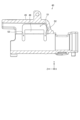
図1は、実施形態のステアリング装置の模式図である。図1に示すように、ステアリング装置80は、ステアリングホイール81と、ステアリングシャフト82と、操舵力アシスト機構83と、第1ユニバーサルジョイント84と、中間シャフト85と、第2ユニバーサルジョイント86と、を備える。
(Embodiment)
Fig. 1 is a schematic diagram of a steering device according to an embodiment of the present invention. As shown in Fig. 1, the
図1に示すように、ステアリングシャフト82は、入力軸82aと、出力軸82bとを備える。入力軸82aの一端は、ステアリングホイール81に接続される。入力軸82aの他端は、出力軸82bに接続される。出力軸82bの一端は、入力軸82aに接続される。出力軸82bの他端は、第1ユニバーサルジョイント84に接続される。
As shown in FIG. 1, the steering
図1に示すように、中間シャフト85の一端は、第1ユニバーサルジョイント84に接続される。中間シャフト85の他端は、第2ユニバーサルジョイント86に接続される。ピニオンシャフト87の一端は、第2ユニバーサルジョイント86に接続される。ピニオンシャフト87の他端は、ステアリングギヤ88に接続される。第1ユニバーサルジョイント84及び第2ユニバーサルジョイント86は、例えばカルダンジョイントである。ステアリングシャフト82の回転は、中間シャフト85を介してピニオンシャフト87に伝わる。第2ユニバーサルジョイント86は、ピニオンシャフト87に接続される。
As shown in FIG. 1, one end of the
図1に示すように、ステアリングギヤ88は、ピニオン88aと、ラック88bとを備える。ピニオン88aは、ピニオンシャフト87に接続される。ラック88bは、ピニオン88aに噛み合う。ステアリングギヤ88は、ピニオン88aに伝達された回転運動をラック88bで直進運動に変換する。ラック88bは、タイロッド89に接続される。ラック88bが移動することで車輪の角度が変化する。
As shown in FIG. 1, the
図1に示すように、操舵力アシスト機構83は、減速装置92と、電動モータ93と、を備える。減速装置92は、例えばウォーム減速装置である。電動モータ93で生じたトルクは、減速装置92の内部のウォームを介してウォームホイールに伝達され、ウォームホイールを回転させる。減速装置92は、ウォーム及びウォームホイールによって、電動モータ93で生じたトルクを増加させる。減速装置92は、出力軸82bに補助操舵トルクを与える。すなわち、ステアリング装置80は、コラムアシスト方式である。
As shown in FIG. 1, the steering force assist
図1に示すように、ステアリング装置80は、ECU(Electronic Control Unit)90と、トルクセンサ94と、車速センサ95と、を備える。電動モータ93、トルクセンサ94及び車速センサ95は、ECU90と電気的に接続される。トルクセンサ94は、入力軸82aに伝達された操舵トルクをCAN(Controller Area Network)通信によりECU90に出力する。車速センサ95は、ステアリング装置80が搭載される車体の走行速度(車速)を検出する。車速センサ95は、車体に備えられ、車速をCAN通信によりECU90に出力する。
As shown in FIG. 1, the
ECU90は、電動モータ93の動作を制御する。ECU90は、トルクセンサ94及び車速センサ95のそれぞれから信号を取得する。ECU90には、イグニッションスイッチ98がオンの状態で、電源装置99(例えば車載のバッテリ)から電力が供給される。ECU90は、操舵トルク及び車速に基づいて補助操舵指令値を算出する。ECU90は、補助操舵指令値に基づいて電動モータ93へ供給する電力値を調節する。ECU90は、電動モータ93から誘起電圧の情報又は電動モータ93に設けられたレゾルバ等から出力される情報を取得する。ECU90が電動モータ93を制御することで、ステアリングホイール81の操作に要する力が小さくなる。
The
図2は、実施形態のステアリング装置の側面図である。以下の説明においては、XYZ直交座標軸が用いられる。X軸は、車両における幅方向(左右方向)と平行である。Z軸は、ステアリングシャフト82の回転軸Rと平行である。Y軸は、X軸及びZ軸の両方に対して直交する。Y軸と平行なY方向のうち車両における上方を+Y方向とする。Z軸と平行なZ方向のうち車両における前方を+Z方向とする。+Y方向を上として+Z方向を向いた場合の右方向を+X方向とする。回転軸Rと平行な方向(Z方向)は、軸方向とも記載される。回転軸Rを中心に放射状に延びる直線に平行な方向は、径方向と記載される。回転軸Rを中心とした円周に沿う方向は、周方向と記載される。
2 is a side view of the steering device of the embodiment. In the following description, XYZ orthogonal coordinate axes are used. The X axis is parallel to the width direction (left-right direction) of the vehicle. The Z axis is parallel to the rotation axis R of the steering
図2に示すように、ステアリング装置80は、ステアリングコラム10と、第1ブラケット20と、第2ブラケット25と、締付部材31と、操作レバー39と、を備える。ステアリングコラム10は、アウターコラム40と、インナーコラム50と、を備える。
As shown in FIG. 2, the
アウターコラム40及びインナーコラム50は、ステアリングシャフト82を、回転軸Rを中心に回転できるように支持する。アウターコラム40は、軸受を介して入力軸82aを支持する。インナーコラム50は、軸受を介して出力軸82bを支持する。アウターコラム40及びインナーコラム50は、筒状の部材である。アウターコラム40及びインナーコラム50は、鋼材等で形成される。図2に示すように、アウターコラム40は、Z方向に延びる第1スリットS1を備える。インナーコラム50は、アウターコラム40に対して+Z方向に配置される。インナーコラム50一部は、アウターコラム40の内側に挿入される。インナーコラム50の外周面は、アウターコラム40の内周面に接する。
The
第1ブラケット20は、ステアリングコラム10を支持する部材である。図2に示すように、第1ブラケット20は、上板21と、側板23と、を備える。上板21は、ステアリングコラム10の+Y方向に配置される。上板21は、車体に固定される。側板23は、上板21から-Y方向に延びている。1つの上板21に、2つの側板23が設けられる。2つの側板23は、X方向に間隔を空けて、平行に配置される。2つの側板23は、アウターコラム40をX方向の両側から挟む。側板23は、Y方向に延びる長穴231を備える。
The
第2ブラケット25は、ステアリングコラム10を、X軸と平行な回転軸を中心として回転できるように支持する部材である。第2ブラケット25は、第1ブラケット20の+Z方向に配置される。第2ブラケット25は、車体に固定される。第2ブラケット25は、例えばピン部材によってインナーコラム50と連結される。ステアリングコラム10は、ピン部材を支点として回転できる。
The
締付部材31は、2つの側板23を締め付けるための部材である。締付部材31は、アウターコラム40及び2つの側板23を貫通する。より具体的には、締付部材31は、一方の側板23の長穴231、アウターコラム40の第1スリットS1、他方の側板23の長穴231の順に貫通する。締付部材31は、アウターコラム40及び側板23からの抜けを防ぐための抜け止め部を両端に備える。締付部材31と側板23との間には、カム機構が設けられる。より具体的には、カム機構は、締付部材31に取り付けられる回転カムと、側板23の長穴231に取り付けられる固定カムと、を備える。
The
側板23の長穴231は、Z方向の大きさが異なる第1長孔231wと、第2長孔231sとを備える。第1長孔231wと、第2長孔231sとは繋がっている。第1長孔231wのZ方向の大きさは、締結部材31の挿入されている部分よりも大きく、第2長孔231sのZ方向の大きさは、締結部材31の挿入されている部分よりも小さい。通常、締付部材31は、側板23の第1長穴231wに挿入されている。ステアリングホイールに対して軸方向に交差する方向の荷重が入力された場合、締付部材31は、側板23の第1長穴231wから第2長孔231sへ移動する。締結部材31は、第2長孔231sの内側を押し広げながら、第2長孔231sに挿入されるので、衝突エネルギーの吸収量が大きくなる。
The
操作レバー39は、締付部材31及び上述したカム機構の回転カムに取り付けられる。操作レバー39が回転すると、締付部材31及び回転カムが回転する一方で、固定カムは回転しない。例えば、固定カムの回転カムに面する表面には、傾斜面が設けられている。回転カムが固定カムの傾斜面に乗り上げることで、回転カムと固定カムとの間の距離が変化する。
The operating
操作レバー39が一方向に回転させられると、側板23がアウターコラム40を締め付ける。側板23とアウターコラム40との摩擦が大きくなるので、ステアリングコラム10が第2ブラケット25を支点として回転できなくなる。このため、ステアリングコラム10のY方向の位置が固定される。また、アウターコラム40とインナーコラム50との間の摩擦が大きくなる。これにより、インナーコラム50に対するアウターコラム40のZ方向の位置が固定される。よって、ステアリングホイール81の位置が固定される。
When the operating
操作レバー39が他方向に回転させられると、側板23によるアウターコラム40の締付が解除される。側板23とアウターコラム40との摩擦が小さくなる又はなくなるので、ステアリングコラム10が第2ブラケット25を支点として回転できるようになる。このため、ステアリングコラム10のY方向の位置調整が可能となる。また、アウターコラム40とインナーコラム50との間の摩擦が小さくなる又はなくなる。これにより、インナーコラム50に対するアウターコラム40のZ方向の位置調整が可能となる。よって、ステアリングホイール81の位置調整が可能となる。
When the operating
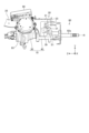
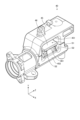
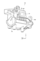
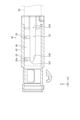
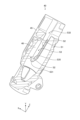
図3から図6は、実施形態のアウターコラムの斜視図である。図7は、実施形態のアウターコラムの正面図である。図8は、実施形態のアウターコラムの右側面図である。図9は、図7のA-A断面図である。図10は、図7のB-B断面図である。図11は、図8のC-C断面図である。図12は、図8のD-D断面図である。図13は、図8のE-E断面図である。図14は、図8のF-F断面図である。図15は、図5のG-G断面図である。 Figures 3 to 6 are perspective views of the outer column of the embodiment. Figure 7 is a front view of the outer column of the embodiment. Figure 8 is a right side view of the outer column of the embodiment. Figure 9 is a cross-sectional view taken along line A-A in Figure 7. Figure 10 is a cross-sectional view taken along line B-B in Figure 7. Figure 11 is a cross-sectional view taken along line C-C in Figure 8. Figure 12 is a cross-sectional view taken along line D-D in Figure 8. Figure 13 is a cross-sectional view taken along line E-E in Figure 8. Figure 14 is a cross-sectional view taken along line F-F in Figure 8. Figure 15 is a cross-sectional view taken along line G-G in Figure 5.
図3に示すように、アウターコラム40は、ハウジング45と、可動部46と、を備える。ハウジング45は、筒状に形成されている。ハウジング45の-Z方向の端部に、入力軸82aが挿入される。ハウジング45の+Z方向の端部に、インナーコラム50及び出力軸82bが挿入される。
As shown in FIG. 3, the
図3に示すように、ハウジング45は、第1スリットS1と、第2スリットS2と、第3スリットS3(図11参照)と、締付面451と、締付面452と、締付面455と、締付面456と、を備える。
As shown in FIG. 3, the
図8に示すように、第1スリットS1は、ハウジング45をX方向に貫通する孔である。第1スリットS1は、Z方向に延びている。すなわち、第1スリットS1は、長手方向がZ方向である長孔である。第1スリットS1は、回転軸Rに対して+Y方向に配置される。第1スリットS1には、締付部材31が挿入される。第1スリットS1のZ方向の長さは、締付部材31の挿入部分の直径よりも大きい。このため、ハウジング45は、締付部材31に対してZ方向に相対的に移動できる。
As shown in FIG. 8, the first slit S1 is a hole that penetrates the
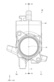
図8に示すように、ハウジング45は、2つの第2スリットS2を備える。第2スリットS2は、ハウジング45の側面から内周面まで貫通する孔である。第2スリットS2は、第1スリットS1と交差する。第2スリットS2は、第1スリットS1のZ方向の端部と繋がっている。第2スリットS2は、第1スリットS1のZ方向の両端から、-Y方向に延びている。X方向から見た場合、第1スリットS1及び2つの第2スリットS2は、略U字を描く。図13に示すように、第2スリットS2は、ハウジング45のうち、平面Pで分割される2つの領域(領域A1及び領域A2)の一方である領域A1のみに設けられる。平面Pは、回転軸Rを含み且つX方向(締付部材31の長手方向)に対して直交する平面である。
As shown in FIG. 8, the
図11に示すように、第3スリットS3は、Z方向に延びる孔である。すなわち、第3スリットS3は、長手方向がZ方向である長孔である。第3スリットS3の一端S31(-Z方向の端部)は、塞がれている。一端S31のZ方向の位置は、第2スリットS2のZ方向の位置に対してずれている。より具体的には、一端S31は、2つの第2スリットS2のうち-Z方向にある第2スリットS2よりも、-Z方向に配置される。第3スリットS3の一部において、第3スリットS3のX方向の幅は、一端S31に向かって小さくなっている。第3スリットS3は、一端S31に向かってX方向の幅が小さくなっているテーパー部分S35を含む。第3スリットS3の他端S32(+Z方向の端部)は、開放している。図12及び図13に示すように、第3スリットS3は、ハウジング45の内周面から第1スリットS1まで貫通している。図13に示すように、第3スリットS3は、第2スリットS2と繋がっている。
As shown in FIG. 11, the third slit S3 is a hole extending in the Z direction. That is, the third slit S3 is a long hole whose longitudinal direction is the Z direction. One end S31 (end in the -Z direction) of the third slit S3 is blocked. The position of the one end S31 in the Z direction is shifted from the position of the second slit S2 in the Z direction. More specifically, the one end S31 is located in the -Z direction further than the second slit S2 in the -Z direction of the two second slits S2. In a part of the third slit S3, the width of the third slit S3 in the X direction becomes smaller toward the one end S31. The third slit S3 includes a tapered portion S35 whose width in the X direction becomes smaller toward the one end S31. The other end S32 (end in the +Z direction) of the third slit S3 is open. As shown in FIG. 12 and FIG. 13, the third slit S3 penetrates from the inner peripheral surface of the
図3に示すように、締付面451は、ハウジング45の+X方向の側面の一部である。締付面451は、X方向に対して直交する平面である。締付面451は、第1スリットS1の+Y方向に配置される。
As shown in FIG. 3, the
図3に示すように、締付面452は、ハウジング45の+X方向の側面の一部である。締付面452は、X方向に対して直交する平面である。締付面452は、第1スリットS1の-Y方向に配置される。締付面452のX方向の位置は、締付面451のX方向の位置に対してずれている。すなわち、締付面452と締付面451とは、同一平面上に配置されていない。具体的には、締付面452は、締付面451よりも+X方向にある。
As shown in FIG. 3, the
図4に示すように、締付面455は、ハウジング45の-X方向の側面の一部である。締付面455は、X方向に対して直交する平面である。締付面455は、第1スリットS1の+Y方向に配置される。
As shown in FIG. 4, the
図4に示すように、締付面456は、ハウジング45の+X方向の側面の一部である。締付面456は、X方向に対して直交する平面である。締付面456は、第1スリットS1の-Y方向に配置される。締付面456のX方向の位置は、締付面455のX方向の位置と同じである。すなわち、締付面456と締付面455とは、同一平面上に配置されている。締付面455及び締付面456は一度に形成できるので、締付面455及び締付面456が同一平面状にない場合と比較して、ハウジング45の加工費が低減される。
As shown in FIG. 4, the
図3に示すように、可動部46は、2つの第2スリットS2の間に配置される。可動部46は、第1スリットS1と、2つの第2スリットS2とに囲まれる。可動部46の-Y方向の端部は、ハウジング45と繋がっている。例えば、可動部46は、ハウジング45と一体成形される。可動部46は、ハウジング45との接合部分を支点として揺動できる。図13に示すように、可動部46は、アウターコラム40のうち、平面Pで分割される2つの領域(領域A1及び領域A2)の一方である領域A1のみに設けられる。
As shown in FIG. 3, the
可動部46は、締付面461を備える。締付面461は、可動部46の側面の一部である。締付面461は、X方向に対して直交する平面である。締付面461は、第1スリットS1の-Y方向に配置される。締付面461は、ハウジング45の締付面451と締付面452との間に配置される。締付部材31による力が可動部46に作用していない状態において、締付面461のX方向の位置は、締付面451のX方向の位置に対してずれている。すなわち、締付面461と締付面451とは、同一平面上に配置されていない。具体的には、締付面461は、締付面451よりも+X方向にある。また、締付部材31による力が可動部46に作用していない状態において、締付面461のX方向の位置は、締付面452のX方向の位置と同じである。すなわち、締付面461と締付面452とは、同一平面上に配置されている。
The
操作レバー39が一方向に回転させられると、側板23がアウターコラム40を締め付ける。具体的には、2つの側板23のうち一方が締付面452及び締付面461に接する。2つの側板23のうち他方が締付面455及び締付面456に接する。締付面461が側板23で押されることによって、可動部46は、インナーコラム50に近づく方向(径方向の内側)に移動する。可動部46がインナーコラム50をアウターコラム40の内周面に押し付ける。これにより、アウターコラム40とインナーコラム50との間の摩擦が大きくなる。その結果、インナーコラム50に対するアウターコラム40のZ方向の位置が固定される。なお、可動部46がある程度変形すると、側板23が締付面451に接する。側板23が締付面451及び締付面452に接することによって、締付面461がそれ以上押されなくなる。これにより、可動部46の過剰な変形が抑制される。
When the operating
操作レバー39が他方向に回転させられると、側板23によるアウターコラム40の締付が解除される。このため、可動部46がインナーコラム50から遠ざかる方向(径方向の外側)に移動する。これにより、アウターコラム40とインナーコラム50との間の摩擦が小さくなる又はなくなる。その結果、インナーコラム50に対するアウターコラム40のZ方向の位置調整が可能となる。
When the operating
以上で説明したように、本実施形態のステアリング装置80は、ステアリングコラム10と、ブラケット(第1ブラケット20)と、締付部材31と、を備える。ステアリングコラム10は、筒状のアウターコラム40、及びアウターコラム40に挿入されるインナーコラム50を備え、ステアリングホイール81に連結されるステアリングシャフト82を回転可能に支持する。ブラケットは、アウターコラム40を挟む側板23を備える。締付部材31は、アウターコラム40及び側板23を貫通する。アウターコラム40は、軸方向(Z方向)に延びており且つ締付部材31が貫通する第1スリットS1と、第1スリットS1と交差する2つの第2スリットS2と、2つの第2スリットS2の間に配置され且つ側板23に接する可動部46と、を備える。第2スリットS2及び可動部46は、アウターコラム40のうち、ステアリングシャフト82の回転軸Rを含み且つ締付部材31の長手方向(X方向)に対して直交する平面Pで分割される2つの領域(領域A1及び領域A2)の一方(領域A1)のみに設けられる。
As described above, the
これにより、締付部材31によって側板23が締め付けられると、可動部46が揺動するが、アウターコラム40のうちの可動部46が設けられていない部分は揺動しない。可動部46がインナーコラム50を押すと、インナーコラム50がアウターコラム40のうち可動部46が設けられていない部分に押し付けられる。すなわち、アウターコラム40のうち剛性の高い部分が、インナーコラム50を支持する。このため、アウターコラム40が両側に可動部46を有する場合と比較して、アウターコラム40がインナーコラム50をより強固に挟む。したがって、本実施形態のステアリング装置80は、アウターコラム40がインナーコラム50を締め付けた状態におけるステアリングコラム10の剛性を高くすることができる。本実施形態のステアリング装置80は、ステアリングホイール81に径方向の荷重が加わった場合でも、アウターコラム40が揺動することを抑制できる。また、可動部46がアウターコラム40の両側にある場合、締付面451と締付面452のように同一平面上にない平面を切削加工で形成する必要がある。これに対して、本実施形態においては可動部46がアウターコラム40の片側にあることによって、切削加工の量を削減することができる。このため、アウターコラム40を製造する時の加工費が低減する。
As a result, when the
本実施形態のステアリング装置80において、アウターコラム40は、内周面から第1スリットS1まで貫通し且つ軸方向に延びる第3スリットS3を備える。2つの第2スリットS2は、第3スリットS3と繋がっている。第3スリットS3の軸方向の一端S31は、塞がれている。一端S31の軸方向の位置は、第2スリットS2の軸方向の位置に対してずれている。
In the
ステアリングホイール81の軸方向の位置を調整する時、アウターコラム40及びインナーコラム50が相対的に移動する。しかし、アウターコラム40及びインナーコラム50は、必ずしも互いに平行な状態で相対的に移動するとは限らない。すなわち、ステアリングホイール81に加わる径方向の力などによって、アウターコラム40がインナーコラム50に対して傾斜している場合がある。このため、インナーコラム50の端部が第2スリットS2に差し掛かる時に、操作者が抵抗を感じることがある。これに対して、本実施形態のステアリング装置80においては、第2スリットS2がアウターコラム40の片側にのみ設けられるので、操作者の感じる抵抗が低減される。さらに、第3スリットS3の一端S31が第2スリットS2とずれているので、インナーコラム50の端部が第2スリットS2に差し掛かるタイミングが、第3スリットS3の一端S31に差し掛かるタイミングとずれる。このため、操作者の感じる抵抗がより低減される。このように、本実施形態のステアリング装置80は、ステアリングホイール81の軸方向の位置を調整する時に、操作者が抵抗を感じにくくすることができる。
When adjusting the axial position of the
本実施形態のステアリング装置80において、第3スリットS3の少なくとも一部にテーパー部分S35があるので、第3スリットS3の幅は、一端S31に向かって小さくなっている。
In the
これにより、第3スリットS3の一端S31の幅を容易に小さくすることができる。このため、インナーコラム50の端部が第3スリットS3に差し掛かる時に、操作者が感じる抵抗が低減される。また、第3スリットS3の幅が一端S31に向かって小さくなっている部分をインナーコラム50の端部が通過する時には、インナーコラム50のうち第3スリットS3に面する範囲が徐々に変化することになる。このため、抵抗が生じたとしても、抵抗の急激な増加は抑制される。したがって、本実施形態のステアリング装置80は、ステアリングホイール81の軸方向の位置を調整する時に、操作者が抵抗を感じにくくすることができる。
This allows the width of one end S31 of the third slit S3 to be easily reduced. Therefore, the resistance felt by the operator when the end of the
インナーコラム50の端部が一方の第2スリットS2の軸方向の一端S2eにさしかかるときに生じる衝撃により、操作者が違和感を覚えることがある。本実施形態のステアリング装置80では、第2スリットS2の一端S2eの軸方向の位置が、第3スリットS3のテーパー部分S35がある位置に重なるので、衝撃が低減され、操作者が違和感を覚えにくくなる。
The operator may feel uncomfortable due to the impact that occurs when the end of the
(第1変形例)
図16は、第1変形例のアウターコラムの断面図である。図16は、第1変形例のアウターコラム40Aの、図8のC-C断面図に相当する断面図である。なお、上述した実施形態で説明したものと同じ構成要素には同一の符号を付して重複する説明は省略する。
(First Modification)
Fig. 16 is a cross-sectional view of an outer column of a first modified example. Fig. 16 is a cross-sectional view of an
図16に示すように、第1変形例のアウターコラム40Aは、第3スリットS3Aを備える。第3スリットS3Aは、Z方向に延びる孔である。第3スリットS3Aの一端S31A(-Z方向の端部)は、塞がれている。一端S31AのZ方向の位置は、第2スリットS2のZ方向の位置に対してずれている。より具体的には、一端S31Aは、2つの第2スリットS2のうち-Z方向にある第2スリットS2よりも、-Z方向に配置される。第3スリットS3の貫通方向(Y方向)から見た場合、一端S31Aは、円弧を描いている。
As shown in FIG. 16, the
これにより、インナーコラム50の端部が第3スリットS3の一端S31Aに差し掛かる時、インナーコラム50のうち第3スリットS3に面する範囲が極めて小さくなる。このため、操作者が感じる抵抗がより低減される。第1変形例のステアリング装置80は、ステアリングホイール81の軸方向の位置を調整する時に、操作者が抵抗をより感じにくくすることができる。
As a result, when the end of the
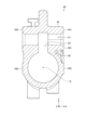
(第2変形例)
図17は、第2変形例のアウターコラムの断面図である。図17は、第2変形例のアウターコラム40Bの、図8のD-D断面図に相当する断面図である。なお、上述した実施形態で説明したものと同じ構成要素には同一の符号を付して重複する説明は省略する。
(Second Modification)
Fig. 17 is a cross-sectional view of an outer column of a second modified example. Fig. 17 is a cross-sectional view of an
図17に示すように、第2変形例のアウターコラム40Bは、ハウジング45Bを備える。ハウジング45Bは、第1凹部458と、第2凹部459と、を備える。第1凹部458及び第2凹部459は、ハウジング45Bの内周面に設けられる溝であって、Z方向に延びている。第1凹部458は、平面Pで分割される2つの領域(領域A1及び領域A2)のうち可動部46側の領域A1に設けられる。第2凹部459は、2つの領域(領域A1及び領域A2)のうち可動部46とは反対側の領域A2に設けられる。第1凹部458は、平面Pを挟んで、第2凹部459と対称に配置される。すなわち、第1凹部458の形状は、回転軸Rを対称点として、第2凹部459の形状と点対称である。第1凹部458の周方向の長さは、第2凹部459の周方向の長さと同じである。
17, the
上述したように、第2変形例のアウターコラム40Bは、2つの領域(領域A1及び領域A2)のうち可動部46側の領域A1の内周面に設けられる第1凹部458と、2つの領域のうち可動部46とは反対側の領域A2の内周面に設けられる第2凹部459と、を備える。
As described above, the
これにより、アウターコラム40Bのうち第1凹部458及び第2凹部459に対応する部分が、インナーコラム50に接触しなくなる。このため、アウターコラム40Bのインナーコラム50との接触部分が、第1凹部458と第2凹部459との間の部分に限定される。具体的には、アウターコラム40Bのインナーコラム50との接触部分が、部分Q1、部分Q2及び部分Q3に限定される。部分Q1は、第1凹部458と第2凹部459との間であって、回転軸Rに対して-Y方向の部分である。部分Q2は、第1凹部458と第3スリットS3との間の部分である。部分Q3は、第2凹部459と第3スリットS3との間の部分である。アウターコラム40Bが特定の複数箇所(部分Q1、部分Q2及び部分Q3)でインナーコラム50に接することによって、インナーコラム50がアウターコラム40Bから受ける垂直抗力が大きくなる。アウターコラム40Bとインナーコラム50との間に生じる摩擦力が大きくなるので、インナーコラム50が強固に固定される。したがって、第2変形例のステアリング装置80は、アウターコラム40Bがインナーコラム50を締め付けた状態におけるステアリングコラム10の剛性を高くすることができる。
As a result, the portions of the
第2変形例のアウターコラム40Bにおいて、第1凹部458は、平面Pを挟んで、第2凹部459と対称に配置される。
In the second modified
これにより、アウターコラム40Bが、平面Pを挟んだ両側から同程度の力でインナーコラム50を挟むことができる。このため、インナーコラム50が強固に固定される。したがって、第2変形例のステアリング装置80は、アウターコラム40Bがインナーコラム50を締め付けた状態におけるステアリングコラム10の剛性を高くすることができる。
This allows the
(第3変形例)
図18は、第3変形例のアウターコラムの断面図である。図18は、第3変形例のアウターコラム40Cの、図8のD-D断面図に相当する断面図である。なお、上述した実施形態で説明したものと同じ構成要素には同一の符号を付して重複する説明は省略する。
(Third Modification)
Figure 18 is a cross-sectional view of an outer column of a third modified example. Figure 18 is a cross-sectional view of an
図18に示すように、第3変形例のアウターコラム40Cは、ハウジング45Cを備える。ハウジング45Cは、第1凹部458Cを備える。第1凹部458Cは、ハウジング45Cの内周面に設けられる溝であって、Z方向に延びている。第1凹部458Cは、平面Pで分割される2つの領域(領域A1及び領域A2)のうち可動部46側の領域A1に設けられる。第1凹部458Cは、平面Pを挟んで、第2凹部459と非対称に配置される。第1凹部458Cの周方向の長さは、第2凹部459の周方向の長さよりも小さい。第1凹部458Cは、第2スリットS2及び締付面452よりも-Y方向に配置される。X方向から見た場合、第1凹部458Cは、第2スリットS2及び締付面452と重ならない。
As shown in FIG. 18, the
上述したように、第3変形例のアウターコラム40Cにおいて、第1凹部458Cの周方向の長さは、第2凹部459の周方向の長さよりも小さい。
As described above, in the
これにより、アウターコラム40Cが特定の複数箇所でインナーコラム50に接することができ、且つ第2スリットS2の端部周辺のアウターコラム40Cの肉厚を大きくすることが可能である。第2スリットS2の端部周辺のアウターコラム40Cの肉厚が大きくすることによって、可動部46の剛性が向上する。このため、可動部46がインナーコラム50をより強く押すことができる。したがって、第3変形例のステアリング装置80は、アウターコラム40Cがインナーコラム50を締め付けた状態におけるステアリングコラム10の剛性を高くすることができる。
This allows the
10 ステアリングコラム
20 第1ブラケット
21 上板
23 側板
25 第2ブラケット
31 締付部材
39 操作レバー
40 アウターコラム
40A アウターコラム
40B アウターコラム
40C アウターコラム
45、45B、45C ハウジング
46 可動部
50 インナーコラム
80 ステアリング装置
81 ステアリングホイール
82 ステアリングシャフト
82a 入力軸
82b 出力軸
83 操舵力アシスト機構
85 中間シャフト
87 ピニオンシャフト
88 ステアリングギヤ
88a ピニオン
88b ラック
89 タイロッド
90 ECU
92 減速装置
93 電動モータ
94 トルクセンサ
95 車速センサ
98 イグニッションスイッチ
99 電源装置
231 長穴
451、452、455、456、461 締付面
A1、A2 領域
P 平面
R 回転軸
S1 第1スリット
S2 第2スリット
S3 第3スリット
S31、S31A 一端
S32 他端
S35 テーパー部分
REFERENCE SIGNS
92
Claims (7)
前記アウターコラムを挟む側板を備えるブラケットと、
前記アウターコラム及び前記側板を貫通する締付部材と、
を備え、
前記アウターコラムは、軸方向に延びており且つ前記締付部材が貫通する第1スリットと、前記第1スリットと繋がって設けられ且つ前記第1スリットと交差する2つの第2スリットと、2つの前記第2スリットの間に配置され且つ前記側板に接する可動部と、を備え、
前記第2スリット及び前記可動部は、前記アウターコラムのうち、前記ステアリングシャフトの回転軸を含み且つ前記締付部材の長手方向に対して直交する平面で分割される2つの領域の一方のみに設けられ、
前記アウターコラムは、内周面から前記第1スリットまで貫通し且つ前記軸方向に延びる第3スリットを備え、
2つの前記第2スリットは、前記第3スリットと繋がっており、
前記軸方向において前記第3スリットの一端は、塞がれており、
前記第3スリットの一端の前記軸方向の位置は、前記第2スリットの前記軸方向の位置に対してずれている、
ステアリング装置。 a steering column including a cylindrical outer column and an inner column inserted into the outer column, the steering column rotatably supporting a steering shaft connected to a steering wheel;
a bracket having side plates that sandwich the outer column;
a fastening member penetrating the outer column and the side plate;
Equipped with
the outer column includes a first slit extending in an axial direction and through which the fastening member passes, two second slits provided to be connected to the first slit and intersect with the first slit, and a movable portion disposed between the two second slits and in contact with the side plate,
the second slit and the movable portion are provided in only one of two regions of the outer column that are divided by a plane that includes a rotation axis of the steering shaft and is perpendicular to a longitudinal direction of the fastening member ,
the outer column includes a third slit penetrating from an inner circumferential surface to the first slit and extending in the axial direction,
The two second slits are connected to the third slit,
One end of the third slit in the axial direction is closed,
A position of one end of the third slit in the axial direction is shifted with respect to a position of the second slit in the axial direction.
Steering gear.
請求項1に記載のステアリング装置。 The steering device according to claim 1 , wherein one end of the third slit describes a circular arc when viewed from a penetrating direction of the third slit.
請求項1又は2に記載のステアリング装置。 At least a part of the third slit has a tapered portion that reduces the width of the third slit toward one end of the third slit.
A steering device according to claim 1 or 2 .
請求項1から4のいずれか1項に記載のステアリング装置。 5. The steering device according to claim 1, wherein the outer column includes a first recess provided on an inner circumferential surface of one of the two regions that is adjacent to the movable portion, and a second recess provided on an inner circumferential surface of one of the two regions that is opposite to the movable portion.
請求項5に記載のステアリング装置。 The steering device according to claim 5 , wherein the first recess is disposed symmetrically to the second recess with respect to the plane.
請求項5に記載のステアリング装置。 The steering device according to claim 5 , wherein a circumferential length of the first recess is smaller than a circumferential length of the second recess.
Priority Applications (1)
| Application Number | Priority Date | Filing Date | Title |
|---|---|---|---|
| JP2021027791A JP7621638B2 (en) | 2021-02-24 | 2021-02-24 | Steering device |
Applications Claiming Priority (1)
| Application Number | Priority Date | Filing Date | Title |
|---|---|---|---|
| JP2021027791A JP7621638B2 (en) | 2021-02-24 | 2021-02-24 | Steering device |
Publications (2)
| Publication Number | Publication Date |
|---|---|
| JP2022129186A JP2022129186A (en) | 2022-09-05 |
| JP7621638B2 true JP7621638B2 (en) | 2025-01-27 |
Family
ID=83150259
Family Applications (1)
| Application Number | Title | Priority Date | Filing Date |
|---|---|---|---|
| JP2021027791A Active JP7621638B2 (en) | 2021-02-24 | 2021-02-24 | Steering device |
Country Status (1)
| Country | Link |
|---|---|
| JP (1) | JP7621638B2 (en) |
Citations (5)
| Publication number | Priority date | Publication date | Assignee | Title |
|---|---|---|---|---|
| US20110204610A1 (en) | 2010-02-23 | 2011-08-25 | Mando Corporation | Steering column for vehicle and steering apparatus having the same |
| JP2014061886A (en) | 2011-02-25 | 2014-04-10 | Nsk Ltd | Telescopic steering device |
| JP2015164851A (en) | 2013-02-13 | 2015-09-17 | 日本精工株式会社 | Outer column and steering column device |
| WO2020100931A1 (en) | 2018-11-15 | 2020-05-22 | 日本精工株式会社 | Outer column and steering device |
| JP2020111110A (en) | 2019-01-09 | 2020-07-27 | 株式会社ジェイテクト | Steering column device |
-
2021
- 2021-02-24 JP JP2021027791A patent/JP7621638B2/en active Active
Patent Citations (5)
| Publication number | Priority date | Publication date | Assignee | Title |
|---|---|---|---|---|
| US20110204610A1 (en) | 2010-02-23 | 2011-08-25 | Mando Corporation | Steering column for vehicle and steering apparatus having the same |
| JP2014061886A (en) | 2011-02-25 | 2014-04-10 | Nsk Ltd | Telescopic steering device |
| JP2015164851A (en) | 2013-02-13 | 2015-09-17 | 日本精工株式会社 | Outer column and steering column device |
| WO2020100931A1 (en) | 2018-11-15 | 2020-05-22 | 日本精工株式会社 | Outer column and steering device |
| JP2020111110A (en) | 2019-01-09 | 2020-07-27 | 株式会社ジェイテクト | Steering column device |
Also Published As
| Publication number | Publication date |
|---|---|
| JP2022129186A (en) | 2022-09-05 |
Similar Documents
| Publication | Publication Date | Title |
|---|---|---|
| US20100004823A1 (en) | Vehicle steering control system | |
| WO2011081076A1 (en) | Electric power steering device | |
| US20180216720A1 (en) | Reducer of electric power steering apparatus | |
| JP5152548B2 (en) | Vehicle steering system | |
| JP4483931B2 (en) | Steering device | |
| JP2006321434A (en) | Steering device | |
| JP7621638B2 (en) | Steering device | |
| JP2018131058A (en) | Steering device | |
| JP7371636B2 (en) | Bracket and steering device | |
| JP5262592B2 (en) | Steering force transmission device for vehicle | |
| JP7734968B2 (en) | Steering gear | |
| JP2011046310A (en) | Vehicular steering device | |
| CN110536825B (en) | Steering device | |
| JP7234636B2 (en) | Bracket and steering gear | |
| JP7286972B2 (en) | steering device | |
| JP7575061B2 (en) | Steering device | |
| JP5451321B2 (en) | Electric power steering device | |
| JP7020303B2 (en) | Steering device and intermediate shaft | |
| JP2014237416A (en) | Steering column device | |
| JP7447713B2 (en) | Connection structure, yoke and intermediate shaft | |
| JP7447615B2 (en) | steering device | |
| JP5175685B2 (en) | Steering force transmission device for vehicle | |
| JP2008126750A (en) | Steering device | |
| JP4487624B2 (en) | Electric steering column device | |
| JP6369045B2 (en) | Steering device |
Legal Events
| Date | Code | Title | Description |
|---|---|---|---|
| A711 | Notification of change in applicant |
Free format text: JAPANESE INTERMEDIATE CODE: A712 Effective date: 20231226 |
|
| A521 | Request for written amendment filed |
Free format text: JAPANESE INTERMEDIATE CODE: A821 Effective date: 20231226 |
|
| A621 | Written request for application examination |
Free format text: JAPANESE INTERMEDIATE CODE: A621 Effective date: 20240206 |
|
| A977 | Report on retrieval |
Free format text: JAPANESE INTERMEDIATE CODE: A971007 Effective date: 20240815 |
|
| A131 | Notification of reasons for refusal |
Free format text: JAPANESE INTERMEDIATE CODE: A131 Effective date: 20240827 |
|
| A521 | Request for written amendment filed |
Free format text: JAPANESE INTERMEDIATE CODE: A523 Effective date: 20241025 |
|
| TRDD | Decision of grant or rejection written | ||
| A01 | Written decision to grant a patent or to grant a registration (utility model) |
Free format text: JAPANESE INTERMEDIATE CODE: A01 Effective date: 20241210 |
|
| A61 | First payment of annual fees (during grant procedure) |
Free format text: JAPANESE INTERMEDIATE CODE: A61 Effective date: 20250107 |
|
| R150 | Certificate of patent or registration of utility model |
Ref document number: 7621638 Country of ref document: JP Free format text: JAPANESE INTERMEDIATE CODE: R150 |