JP7621637B2 - Bird damage prevention equipment - Google Patents
Bird damage prevention equipment Download PDFInfo
- Publication number
- JP7621637B2 JP7621637B2 JP2021015519A JP2021015519A JP7621637B2 JP 7621637 B2 JP7621637 B2 JP 7621637B2 JP 2021015519 A JP2021015519 A JP 2021015519A JP 2021015519 A JP2021015519 A JP 2021015519A JP 7621637 B2 JP7621637 B2 JP 7621637B2
- Authority
- JP
- Japan
- Prior art keywords
- semi
- prevention device
- pest prevention
- cylindrical body
- cylindrical
- Prior art date
- Legal status (The legal status is an assumption and is not a legal conclusion. Google has not performed a legal analysis and makes no representation as to the accuracy of the status listed.)
- Active
Links
- 230000002265 prevention Effects 0.000 title claims description 94
- 241000607479 Yersinia pestis Species 0.000 claims description 91
- 230000001105 regulatory effect Effects 0.000 claims description 18
- 230000005484 gravity Effects 0.000 claims description 7
- 238000003780 insertion Methods 0.000 claims description 6
- 230000037431 insertion Effects 0.000 claims description 6
- 241000271566 Aves Species 0.000 description 7
- 208000028804 PERCHING syndrome Diseases 0.000 description 3
- 238000010586 diagram Methods 0.000 description 3
- 238000000034 method Methods 0.000 description 2
- 241000272201 Columbiformes Species 0.000 description 1
- 241000269799 Perca fluviatilis Species 0.000 description 1
- 230000000694 effects Effects 0.000 description 1
- 210000003608 fece Anatomy 0.000 description 1
- 238000009434 installation Methods 0.000 description 1
- 238000009413 insulation Methods 0.000 description 1
- 238000012986 modification Methods 0.000 description 1
- 230000004048 modification Effects 0.000 description 1
Images


Landscapes
- Catching Or Destruction (AREA)
- Suspension Of Electric Lines Or Cables (AREA)
Description
本発明は、鳥害を防止するために、電線等の架空ケーブルに取り付けられる鳥害防止具に関する。 The present invention relates to a bird pest prevention device that is attached to overhead cables such as electric wires to prevent bird damage.
鳩等の鳥は、電線等の架空ケーブルに留まる習性を持っている。架空ケーブルに常習的に多数の鳥が留まると、架空ケーブルの被覆が損傷したり、あるいは、鳥の糞が当該架空ケーブルの下に落下して溜まったりする等といった鳥害が発生する。 Birds such as pigeons have a habit of perching on overhead cables such as power lines. If a large number of birds habitually perch on overhead cables, this can cause bird damage, such as damage to the cable's insulation or bird droppings falling and accumulating underneath the overhead cables.
このような鳥害を防止するため、予め架空ケーブルに取り付けておくことによって鳥が当該架空ケーブルに留まることをできなくする鳥害防止具が開発されている(例えば、特許文献1)。 To prevent such bird damage, bird prevention devices have been developed that are attached to overhead cables in advance to prevent birds from staying on the cables (for example, Patent Document 1).
特許文献1に開示された鳥害防止具は、一対の半筒体を互いに組み合わせることによって略円筒形状体となり、この略円筒形状体の表面から多数の突出針が突出されている。一対の半筒体で架空ケーブルを挟み込むようにして鳥害防止具を取り付けることにより、多数の突出針が邪魔をして鳥が架空ケーブルに留まることができなくなる。
The bird pest prevention device disclosed in
しかしながら、特許文献1に開示された鳥害防止具に代表される従来の鳥害防止具は、バランスが悪いことから、架空ケーブルに取り付ける際に一人の作業者で取り付け作業をスムーズに行うのが難しいという問題があった。
However, conventional bird pest prevention devices, such as the one disclosed in
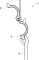
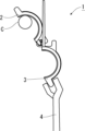
具体的に説明すると、従来の鳥害防止具1の取り付けは、図20に示すように、一方の半筒体2の一端に他方の半筒体3の一端が回動可能に取り付けられており、一方の半筒体2に対して他方の半筒体3を完全に開いた状態を保持しつつ、ヤットコ等の工具4で架空ケーブルCに一方の半筒体2(図21)あるいは他方の半筒体3(図22)の内面に掛け、然る後、架空ケーブルCに掛けられた方の半筒体の位置を保持しつつ、別の工具を用いて別の半筒体を回動させて略円筒形状体を完成させるようになっていた。つまり、従来の鳥害防止具1の取り付けには少なくとも2つの工具を用いる必要があり、一人の作業者によってスムーズに取り付け作業を実施するのが困難であった。
To be more specific, as shown in Fig. 20, the conventional bird
本発明は、このような課題に鑑みてなされたものであり、その目的は、一人の作業者によってスムーズに取り付け作業を実施できる鳥害防止具を提供することにある。 The present invention was made in consideration of these problems, and its purpose is to provide a bird pest prevention device that can be installed smoothly by a single worker.
本発明の一局面によれば、
一対の半筒状体と、
少なくともいずれか一つの前記半筒状体に設けられた鳥回避部材とを備える鳥害防止具であって、
一方の前記半筒状体に形成された、一方の前記半筒状体が延びる方向と平行に延びる被挿入部に対して、他方の前記半筒状体に形成された、他方の前記半筒状体が延びる方向と平行に延びる円柱状部が挿入されることにより、一方の前記半筒状体は、他方の前記半筒状体に対して長手方向端縁を軸として回動可能に取り付けられており、
少なくとも一方の前記半筒状体には、他方の前記半筒状体に対する一方の前記半筒状体の開き角を規制する開き角規制部が形成されていることを特徴とする
鳥害防止具が提供される。
According to one aspect of the present invention,
A pair of semi-cylindrical bodies;
A bird pest prevention device comprising a bird avoidance member provided on at least one of the semi-cylindrical bodies,
a cylindrical portion formed on one of the semi-cylindrical bodies and extending parallel to the extension direction of the other semi-cylindrical body is inserted into an insertion portion formed on one of the semi-cylindrical bodies and extending parallel to the extension direction of the other semi-cylindrical body, so that one of the semi-cylindrical bodies is attached to the other semi-cylindrical body so as to be rotatable about a longitudinal end edge as an axis;
At least one of the semi-cylindrical bodies is provided with an opening angle regulating portion for regulating an opening angle of the one semi-cylindrical body relative to the other semi-cylindrical body.
好適には、
前記開き角規制部は、前記鳥害防止具の長手方向に直交する面で見て、架空ケーブルの垂直下方に前記鳥害防止具の重心位置がくるようにしたとき、一方または他方の前記半筒状体の内面が前記架空ケーブルに掛かった状態となる前記開き角に規制する。
Preferably,
The opening angle regulating portion regulates the opening angle to such a state that when the center of gravity of the bird pest prevention device is positioned vertically below the overhead cable, when viewed in a plane perpendicular to the longitudinal direction of the bird pest prevention device, the inner surface of one or the other of the semi-cylindrical bodies is hung on the overhead cable.
また、本発明の他の局面によれば、
一対の半筒状体と、
少なくともいずれか一つの前記半筒状体に設けられた鳥回避部材とを備える鳥害防止具であって、
一方の前記半筒状体に形成された、一方の前記半筒状体が延びる方向と平行に延びる被挿入部に対して、他方の前記半筒状体に形成された、他方の前記半筒状体が延びる方向と平行に延びる円柱状部が挿入されることにより、一方の前記半筒状体は、他方の前記半筒状体に対して長手方向端縁を軸として回動可能に取り付けられており、
少なくとも一方の前記半筒状体には、一方の前記半筒状体を他方の前記半筒状体に対して閉じる方向に常に付勢する開き角規制部が形成されていることを特徴とする
鳥害防止具。
According to another aspect of the present invention,
A pair of semi-cylindrical bodies;
A bird pest prevention device comprising a bird avoidance member provided on at least one of the semi-cylindrical bodies,
a cylindrical portion formed on one of the semi-cylindrical bodies and extending parallel to the extension direction of the other semi-cylindrical body is inserted into an insertion portion formed on one of the semi-cylindrical bodies and extending parallel to the extension direction of the other semi-cylindrical body, so that one of the semi-cylindrical bodies is attached to the other semi-cylindrical body so as to be rotatable about a longitudinal end edge as an axis;
A bird pest prevention device, characterized in that at least one of the semi-cylindrical bodies is formed with an opening angle regulating portion that constantly urges the one semi- cylindrical body in a direction to close relative to the other semi-cylindrical body.
さらに、本発明の他の局面によれば、
一対の半筒状体と、
少なくともいずれか一つの前記半筒状体に設けられた鳥回避部材とを備える鳥害防止具であって、
一方の前記半筒状体は、他方の前記半筒状体に対して長手方向端縁を軸として回動可能に取り付けられており、
一対の前記半筒状体には、それぞれ一対の前記半筒状体を閉じる方向に付勢する重り部が形成されており、かつ、
一対の前記重り部には、反対側の前記重り部によって一対の前記半筒状体が閉じられる際に工具で掴まれる工具掴み部がそれぞれ形成されていることを特徴とする
鳥害防止具が提供される。
Furthermore, according to another aspect of the present invention,
A pair of semi-cylindrical bodies;
A bird pest prevention device comprising a bird avoidance member provided on at least one of the semi-cylindrical bodies,
one of the semi-cylindrical bodies is attached to the other of the semi-cylindrical bodies so as to be rotatable about a longitudinal end edge as an axis;
A weight portion is formed on each of the pair of semi-cylindrical bodies to bias the pair of semi-cylindrical bodies in a direction to close the pair of semi-cylindrical bodies , and
The bird pest prevention device is characterized in that a pair of the weight portions are each formed with a tool gripping portion that is gripped with a tool when the pair of the semi-cylindrical bodies are closed by the weight portion on the opposite side .
好適には、
前記重り部は、少なくともいずれか一つの前記半筒状体における前記軸とは反対側の長手方向端縁に形成されている。
Preferably,
The weight portion is formed on a longitudinal end edge of at least one of the semi-cylindrical bodies on the side opposite to the axis.
好適には、
前記重り部は、前記鳥害防止具の本体部よりも外側に形成されている。
Preferably,
The weight portion is formed outside the main body portion of the bird pest prevention device.
好適には、
前記重り部は、両方の前記半筒状体にそれぞれ形成されている。
Preferably,
The weight portions are formed on both of the semi-cylindrical bodies.
本発明の一局面によれば、開き角規制部によって他方の半筒状体に対する一方の半筒状体の開き角が規制されるので、一人の作業者が工具を用いて一方あるいは他方の半筒体の内面を架空ケーブルに掛けた後で鳥害防止具から工具を離しても当該鳥害防止具は落下することなく架空ケーブルに掛かったままの状態を維持できる。また、風等で鳥害防止具が揺れても架空ケーブルから落下するおそれが少なくなる。これにより、一人の作業者によってスムーズに取り付け作業を実施できる鳥害防止具を提供することができた。 According to one aspect of the present invention, the opening angle of one semi-cylindrical body relative to the other semi-cylindrical body is regulated by the opening angle regulating portion, so that even if a single worker uses a tool to hang the inner surface of one or the other semi-cylindrical body on the overhead cable and then removes the tool from the bird pest prevention device, the bird pest prevention device will not fall off and will remain hung on the overhead cable. In addition, even if the bird pest prevention device is swayed by wind, etc., there is less risk of it falling off the overhead cable. This makes it possible to provide a bird pest prevention device that can be installed smoothly by a single worker.
また、本発明の他の局面によれば、他方の半筒状体に対して一方の半筒状体が開いた状態で、重り部によって一対の半筒状体が閉じる方向に付勢されるので、一人の作業者が工具を用いて架空ケーブルに他方の半筒状体の内面を掛けたときに一方の半筒状体が速やかに閉じてくるとともに、風等の影響で一方の半筒状体が勝手に開き難くなる。これにより、一人の作業者によってスムーズに取り付け作業を実施できる鳥害防止具を提供することができた。 According to another aspect of the present invention, when one half-cylinder is open relative to the other half-cylinder, the pair of half-cylinders are biased in the closing direction by the weight portion, so that when a worker uses a tool to hook the inner surface of the other half-cylinder onto the overhead cable, one half-cylinder quickly closes and is less likely to open on its own due to the influence of wind, etc. This makes it possible to provide a bird pest prevention device that can be installed smoothly by a single worker.
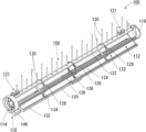
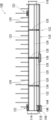
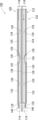
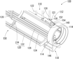
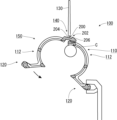
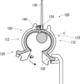
(鳥害防止具100の構成)
本発明が適用された実施形態に係る鳥害防止具100について説明する。図1は鳥害防止具100の斜視図であり、図2は鳥害防止具100の正面図であり、図3は鳥害防止具100の平面図であり、図4は鳥害防止具100の底面図であり、図5は鳥害防止具100の右側面図である。また、図6は鳥害防止具100の一端側を示す拡大斜視図である。
(Configuration of bird damage prevention device 100)
A bird
本実施形態に係る鳥害防止具100は、大略、第1の半筒状体110と、第2の半筒状体150とで構成されている。
The bird
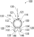
第1の半筒状体110は、大略、本体部112と、雌連結部114と、雄連結部116と、係合部118と、重り部120と、開閉機構部121とを有している。
The first
本体部112は、天面部122と、側部124と、底部126と、半円状部128と、突出針130とを有している。
The
天面部122は、架空ケーブルCに対して鳥害防止具100を正しく取り付けたときに鉛直方向の上面に位置する略矩形状の長尺部分である。また、天面部122の外面からは、外方に向けて複数の突出針130が突設されている。
The
側部124は、天面部122に対して略平行に延びる長尺部分であり、天面部122よりも細幅に形成されている。
The
底部126は、天面部122や側部124に対して略平行に延びる長尺部分であり、側部124とほぼ同じ幅に形成されている。
The
半円状部128は、互いに略平行に配設されている上記天面部122、側部124、および底部126を一定の位置関係で保持する役割を有する半円状の部分である。半円状部128の形状により、第1の半筒状体110は略半円筒の形状となっている。なお、本実施形態では3つの半円状部128が形成されているが、半円状部128の数は特に限定されるものではなく、例えば本体部112の長さに応じて半円状部128の数を設定するのが好適である。
The
突出針130は、架空ケーブルCに取り付けた鳥害防止具100に対して鳥が留まることができないようにするための部分であり、本実施形態では、天面部122の長手方向に沿って、長さの長い突出針130と長さの短い突出針130とが交互に並ぶようにして、複数の突出針130が所定の間隔で配置されている。突出針130の長さはこれに限定されるものではなく、例えば、すべての突出針130を同じ長さに設定してもよいし、すべての突出針130を互いに異なる長さに設定してもよい。
The protruding needles 130 are parts that prevent birds from landing on the bird
雌連結部114は、上述した本体部112における一方の端部に形成されており、複数の鳥害防止具100を長手方向に連結する際、別の鳥害防止具100に形成された雄連結部116の外周を覆う部分である。
The
また、雄連結部116は、本体部112における他方の端部に形成されており、複数の鳥害防止具100を長手方向に連結する際、その外周が別の鳥害防止具100に形成された雌連結部114によって覆われる部分である。
The
なお、雌連結部114および雄連結部116は、複数の鳥害防止具100を長手方向に連結できるものであればどのような形状であってもよい。例えば、鳥害防止具100に形成された雄連結部116をその長手方向に移動させて別の鳥害防止具100の雌連結部114に挿入連結できるように、雌連結部114および雄連結部116をテーパー状に形成してもよい。さらに言えば、複数の鳥害防止具100を連結する必要がない場合は、雌連結部114および雄連結部116は必要ではなくなる。
The
係合部118は、第1の半筒状体110と第2の半筒状体150とを閉じて略円筒形状体の鳥害防止具100とした状態を維持するための部分であり、第1の半筒状体110には、第2の半筒状体150に形成された凸状部156(係合部118)を受け入れる係合孔144と、当該係合孔144よりも第1の半筒状体110の中心から離れた位置に形成された、係合時に工具で挟まれる被挟み部146とを有している(特に図2を参照)。
The engaging
また、本実施形態において、係合部118は、本体部112における雌連結部114が形成された一方の端部の底側に形成されているが、係合部118の位置はこれに限定されるものではなく、本体部112における底側であればどの位置に形成されていてもよいし、また、係合部118の数も本実施形態のように1箇所ではなく、複数箇所に形成してもよい。
In addition, in this embodiment, the
重り部120は、第2の半筒状体150に対して第1の半筒状体110が回動する際の軸となる開閉機構部121が設けられたのとは反対側の長手方向端縁に形成されており、大略、長手棒状部132と、複数のステー部134とで構成されている。なお、重り部120の位置は、当該重り部120が一対の半筒状体110,150を閉じる方向に付勢できるものであれば、開閉機構部121が設けられたのとは反対側の長手方向端縁に限定されず、いずれの位置にあってもよい。
The
長手棒状部132は、本体部112の天面部122、側部124、および底部126と略平行に配置された棒状部分であり、鳥害防止具100を保持する際に工具で掴む工具掴み部136が略中央部に形成されている。長手棒状部132に形成する工具掴み部136の位置は、中央部に限定されるものではないが、工具で鳥害防止具100を保持したときのバランスから、工具掴み部136を略中央部に形成するのが好適である。
The
ステー部134は、長手棒状部132を本体部112よりも外側に配置するための部分である。ステー部134の一端は、本体部112における底部126に接続されており、他端は、長手棒状部132に接続されている。また、本実施形態では、5つのステー部134が互いにほぼ同じ間隔で並べて形成されている。もちろん、ステー部134の数や配置間隔はこれに限定されるものではなく、長手棒状部132を本体部112よりも外側に配置できるものであれば、どのような態様であってもよい。
The
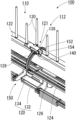
開閉機構部121は、図7に示すように、第2の半筒状体150に対して第1の半筒状体110がその長手方向端縁を軸として回動可能に取り付けられるようにする機構部である。開閉機構部121は、第1の半筒状体110における本体部112における両端部にそれぞれ形成されており、大略、被挿入部138と、開き角規制部140とを有している。
As shown in FIG. 7, the opening/
被挿入部138は、本体部112の天面部122と平行に延びる断面が略C字状の部分である。つまり、断面における略C字状部分に対応する溝部142が天面部122と平行に形成されている。そして、当該溝部142の奥において、第2の半筒状体150に形成された開閉機構部121の円柱状部152が天面部122と平行に挿入されるようになっている。
The inserted
開き角規制部140は、被挿入部138の端縁から突設された部分である。この開き角規制部140は、第1の半筒状体110に対する第2の半筒状体150の開き角が所定の角度となったときに、第2の半筒状体150に形成された開閉機構部121の円柱状部152を支持する支持部154に当接する位置に設けられている。これにより、第1の半筒状体110に対する第2の半筒状体150の開き角が所定の角度よりも大きくなるのを規制することができる。なお、開き角規制部140は、本実施形態に限定されるものではなく、第1の半筒状体110に対する第2の半筒状体150の開き角が所定の角度よりも大きくなるのを規制することができるものであれば、他の態様であってもよい。
The opening
次に、図1から図6に戻り、第2の半筒状体150の構成について説明する。第2の半筒状体150の構成は基本的に上述した第1の半筒状体110と同じであることから、第1の半筒状体110と異なる部分についてのみ説明し、それ以外の部分については第1の半筒状体110における説明を援用する。
Next, returning to FIG. 1 to FIG. 6, the configuration of the second
第2の半筒状体150における係合部118は、第1の半筒状体110と第2の半筒状体150とを閉じて略円筒形状体の鳥害防止具100とした状態を維持するための部分であり、第2の半筒状体150における係合部118は、第1の半筒状体110に形成された係合孔144に挿設される凸状部156と、当該凸状部156よりも第2の半筒状体150の中心から離れた位置に形成された、係合時に工具で挟まれる被挟み部146とを有している。(特に図2を参照)
The engaging
また、第1の半筒状体110で説明したのと同様に、本実施形態における係合部118は、本体部112における雌連結部114が形成された一方の端部側の底側に形成されているが、係合部118の位置はこれに限定されるものではなく、本体部112における底側であればどの位置に形成されていてもよいし、また、係合部118の数も本実施形態のように1箇所ではなく、複数箇所に形成してもよい。
As explained for the first
第2の半筒状体150における開閉機構部121は、図7に示すように、本体部112における両端部にそれぞれ形成されており、大略、円柱状部152と、支持部154とを有している。
As shown in FIG. 7, the opening/
円柱状部152は、本体部112の天面部122と平行に延びる断面が略円形の部分である。また、支持部154は、その一端が円柱状部152の一端に接続されているとともに、他端が第2の半筒状体150における天面部122に接続された部分であり、円柱状部152を天面部122から離間させた状態で支持する役割を有している。
The
さらに、支持部154は、第1の半筒状体110に対する第2の半筒状体150の開き角が所定の角度となったときに、第1の半筒状体110に形成された開閉機構部121の開き角規制部140に当接する位置に設けられている。
Furthermore, the
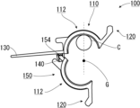
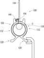
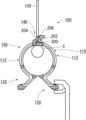
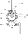
第1の半筒状体110に形成された開き角規制部140と第2の半筒状体150に形成された支持部154とが当接するときの第1の半筒状体110に対する第2の半筒状体150の開き角は、図8および図9に示すように、鳥害防止具100の長手方向に直交する面で見て、架空ケーブルCの垂直下方に鳥害防止具100の重心位置Gがくるようにしたとき、第1の半筒状体110あるいは第2の半筒状体150の内面が架空ケーブルCに掛かった状態となるように設定にするのが好適である。第1の半筒状体110に対する第2の半筒状体150の開き角が大きくなればなるほど、鳥害防止具100の重心位置Gは天面部122に近づいていくので、上述のように架空ケーブルCに掛かった状態となり難くなる。
When the opening
(鳥害防止具100の特徴)
本実施形態に係る鳥害防止具100によれば、開き角規制部140によって第1の半筒状体110に対する第2の半筒状体150の開き角が規制されるので、一人の作業者が工具を用いて第1の半筒状体110あるいは第2の半筒状体150の内面を架空ケーブルCに掛けた後で鳥害防止具100から工具を離しても当該鳥害防止具100は落下することなく架空ケーブルCに掛かったままの状態を維持できる(図8および図9)。また、風等で鳥害防止具100が揺れても架空ケーブルCから落下するおそれが少なくなる。これにより、一人の作業者によってスムーズに取り付け作業を実施できる鳥害防止具100を提供することができる。
(Features of bird pest prevention device 100)
According to the bird
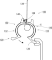
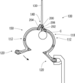
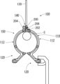
また、重り部120の長手棒状部132が本体部112よりも外側に配置されていることにより、第1の半筒状体110に対して第2の半筒状体150が開いた状態で、重り部120によって一対の半筒状体110,150が閉じる方向に付勢されるので、図10から図12に示すように、一人の作業者が工具を用いて架空ケーブルCに第1の半筒状体110の内面を掛けたときに第2の半筒状体150が速やかに閉じてくるとともに、風等の影響で第2の半筒状体150が勝手に開き難くなる。これにより、一人の作業者によってスムーズに取り付け作業を実施できる鳥害防止具100を提供することができる。
In addition, because the
さらに、本実施形態の鳥害防止具100の本体部112は、上述のように、略矩形状の長尺部材である天面部122と、細い部材である側部124および底部126とで基本的に構成されており「面」部分がほとんど存在しないことから、当該鳥害防止具100は風等の影響を受け難い「耐風性が強い」ものになっている。
Furthermore, as described above, the
(変形例1)
上述した実施形態では、第1の半筒状体110および第2の半筒状体150は、それぞれ略半円筒状に形成されており、これらを組み合わせて形成される鳥害防止具100の外形は略円筒状に形成されていたが、これに変えて、第1の半筒状体110および第2の半筒状体150をそれぞれ略半角筒状に形成して、略角筒状の鳥害防止具100としてもよい。
(Variation 1)
In the above-described embodiment, the first
(変形例2)
上述した実施形態では、重り部120は本体部112に略平行な長手棒状部132を有していたが、これに変えて、各ステー部134の先端に個別独立した球状・角状等の重りを本体部112よりも外側に配置してもよい。もちろん、この重りとステー部134のセット数も、1つでもよいし、複数であってもよい。さらに言えば、重り部120を本体部112よりも内側に配置してもよい。
(Variation 2)
In the above-described embodiment, the
(変形例3)
上述した実施形態では、第1の半筒状体110および第2の半筒状体150の両方に重り部120を設けているが、これに変えて、第1の半筒状体110および第2の半筒状体150のいずれか一方のみに重り部120を設け、いずれか他方に工具掴み部136を設けてもよい。ただし、上述した実施形態のように第1の半筒状体110および第2の半筒状体150の両方に重り部120を設ける方が、第1の半筒状体110および第2の半筒状体150のどちらを工具で保持してもよく施工性が高まる点で好適である。
(Variation 3)
In the above-described embodiment, the
(変形例4)
上述した実施形態では、開閉機構部121の一例として、第1の半筒状体110に形成された被挿入部138および開き角規制部140と、第2の半筒状体150に形成された円柱状部152および支持部154とで構成されたものを示したが、開閉機構部121は、第2の半筒状体150に対して第1の半筒状体110がその長手方向端縁を軸として回動可能に取り付けられるものであれば他の態様であってもよい。
(Variation 4)
In the above-described embodiment, an example of the opening/
例えば、図13および図14に示すように、開閉機構部121を、第1の半筒状体110に形成された開閉用舌片受入部200、および、この開閉用舌片受入部200に形成された舌片受入孔202と、第2の半筒状体150に形成された開閉用舌片204とで構成してもよい。開閉用舌片204は、第2の半筒状体150の天面から斜め上方に突設された部分であり、その先端には、開閉用舌片204を舌片受入孔202に挿設したときに当該開閉用舌片204が不所望に抜け出るのを防止するための舌片突部206が形成されている。
For example, as shown in Figures 13 and 14, the opening/
舌片突部206が形成された部分以外の開閉用舌片204の厚さは、舌片受入孔202の大きさよりも小さく形成されている。これにより、開閉用舌片204を舌片受入孔202に挿設した状態において、舌片受入孔202の中で開閉用舌片204がある程度動くことができる余裕があるので、この余裕の範囲内で第2の半筒状体150に対して第1の半筒状体110がその長手方向端縁を軸として回動可能となる。
The thickness of the opening/
第2の半筒状体150に対する第1の半筒状体110の開き角を小さくしたければ、開閉用舌片204の厚さを舌片受入孔202の大きさに近づければよく、当該開き角を大きくしたければ、開閉用舌片204の厚さを舌片受入孔202の大きさよりもさらに小さくすればよい。
If it is desired to reduce the opening angle of the first
つまり、この実施形態では、開閉用舌片204および舌片受入孔202が開き角規制部140を構成することになる。
In other words, in this embodiment, the opening/
また、図15および図16に示すように、開閉用舌片204の厚さを自身が簡単に撓む程度に薄く形成するとともに、舌片受入孔202の大きさを開閉用舌片204の厚さとほぼ同じに設定してもよい。
Also, as shown in Figures 15 and 16, the thickness of the opening/
この態様の場合、舌片受入孔202の中で開閉用舌片204が動くことはほとんど無いが、開閉用舌片204自身が撓むことにより、撓みの範囲内で第2の半筒状体150に対して第1の半筒状体110がその長手方向端縁を軸として回動可能となる。
In this embodiment, the opening/
第2の半筒状体150に対する第1の半筒状体110の開き角を小さくしたければ、開閉用舌片204を撓みにくい厚さに設定すればよく、当該開き角を大きくしたければ、開閉用舌片204の厚さをさらに薄く設定すればよい。
If it is desired to reduce the opening angle of the first
つまり、この実施形態では、開閉用舌片204が開き角規制部140を構成することになる。
In other words, in this embodiment, the opening and
(変形例5)
上述した実施形態では、鳥害防止具100に対して鳥が留まることができないようにする「鳥回避部材」として突出針130を設けているが、これに変えて、鳥害防止具100を架空ケーブルCに取り付けた状態で、本体部112から鉛直上方に離間し、かつ、当該本体部112と略平行に延びる紐部材を設ける等、突出針130以外の「鳥回避部材」を用いて鳥が留まることができないようにしてもよい。
(Variation 5)
In the above-described embodiment, the protruding
(変形例6)
上述した実施形態では、開き角規制部140は第1の半筒状体110に対する第2の半筒状体150の開き角が所定の角度となったときに支持部154に当接する位置に設けられていたが、これに変えて、図17から図19に示すように、開き角規制部140を支持部154に向けて延長してもよい。具体的には、第1の半筒状体110と第2の半筒状体150とが互いに閉じた状態でも開き角規制部140が支持部154に対して当接するようにしておき、第2の半筒状体150に対して第1の半筒状体110を開いていく際には、開き角規制部140や支持部154、さらには第1の半筒状体110や第2の半筒状体150を少し変形させるようにする。つまり、互いに当接している開き角規制部140および支持部154により、第1の半筒状体110および第2の半筒状体150は、常に閉じる方向の力が付与されていることになる。
(Variation 6)
In the above embodiment, the opening
これにより、一人の作業者が工具を用いて第1の半筒状体110あるいは第2の半筒状体150の内面を架空ケーブルCに掛けようとしている最中に、万一、当該工具から鳥害防止具100が外れてしまっても、上述のように第1の半筒状体110および第2の半筒状体150には常に閉じる方向の力が付与されているので、鳥害防止具100が架空ケーブルCから落下する可能性を低減できる。
As a result, even if the bird
今回開示された実施形態はすべての点で例示であって制限的なものではないと考えられるべきである。本発明の範囲は、上記した説明ではなく、特許請求の範囲によって示され、特許請求の範囲と均等の意味および範囲内でのすべての変更が含まれることが意図される。 The embodiments disclosed herein should be considered to be illustrative and not restrictive in all respects. The scope of the present invention is indicated by the claims, not by the above description, and is intended to include all modifications within the meaning and scope of the claims.
100…鳥害防止具
110…第1の半筒状体、112…本体部、114…雌連結部、116…雄連結部、118…係合部、120…重り部、121…開閉機構部、122…天面部、124…側部、126…底部、128…半円状部、130…突出針、132…長手棒状部、134…ステー部、136…工具掴み部、138…被挿入部、140…開き角規制部、142…溝部、144…係合孔、146…被挟み部
150…第2の半筒状体、152…円柱状部、154…支持部、156…凸状部
200…開閉用舌片受入部、202…舌片受入孔、204…開閉用舌片、206…舌片突部
C…架空ケーブル、G…重心位置
100: Bird pest prevention device 110: First semi-cylindrical body, 112: Main body, 114: Female connection part, 116: Male connection part, 118: Engagement part, 120: Weight part, 121: Opening and closing mechanism part, 122: Top surface part, 124: Side part, 126: Bottom part, 128: Semi-circular part, 130: Protruding needle, 132: Long rod part, 134: Stay part, 136: Tool gripping part, 138: Inserted part, 140: Opening angle regulating part, 142: Groove part, 144: Engagement hole, 146: Clamped part 150: Second semi-cylindrical body, 152: Cylindrical part, 154: Support part, 156: Convex part 200: Opening/closing tongue receiving portion, 202: Tongue receiving hole, 204: Opening/closing tongue, 206: Tongue protrusion C: Aerial cable, G: Center of gravity position
Claims (7)
少なくともいずれか一つの前記半筒状体に設けられた鳥回避部材とを備える鳥害防止具であって、
一方の前記半筒状体に形成された、一方の前記半筒状体が延びる方向と平行に延びる被挿入部に対して、他方の前記半筒状体に形成された、他方の前記半筒状体が延びる方向と平行に延びる円柱状部が挿入されることにより、一方の前記半筒状体は、他方の前記半筒状体に対して長手方向端縁を軸として回動可能に取り付けられており、
少なくとも一方の前記半筒状体には、他方の前記半筒状体に対する一方の前記半筒状体の開き角を規制する開き角規制部が形成されていることを特徴とする
鳥害防止具。 A pair of semi-cylindrical bodies;
A bird pest prevention device comprising a bird avoidance member provided on at least one of the semi-cylindrical bodies,
a cylindrical portion formed on one of the semi-cylindrical bodies and extending parallel to the extension direction of the other semi-cylindrical body is inserted into an insertion portion formed on one of the semi-cylindrical bodies and extending parallel to the extension direction of the other semi-cylindrical body, so that one of the semi-cylindrical bodies is attached to the other semi-cylindrical body so as to be rotatable about a longitudinal end edge as an axis;
A bird pest prevention device, characterized in that at least one of the semi-cylinders is formed with an opening angle regulating portion that regulates an opening angle of the one semi-cylinder with respect to the other semi-cylinder.
請求項1に記載の鳥害防止具。 The bird pest prevention device according to claim 1, wherein the opening angle regulating portion regulates the opening angle to such an extent that when the center of gravity of the bird pest prevention device is positioned vertically below the overhead cable, when viewed in a plane perpendicular to the longitudinal direction of the bird pest prevention device, the inner surface of one or the other of the semi-cylindrical bodies is hung on the overhead cable.
少なくともいずれか一つの前記半筒状体に設けられた鳥回避部材とを備える鳥害防止具であって、
一方の前記半筒状体に形成された、一方の前記半筒状体が延びる方向と平行に延びる被挿入部に対して、他方の前記半筒状体に形成された、他方の前記半筒状体が延びる方向と平行に延びる円柱状部が挿入されることにより、一方の前記半筒状体は、他方の前記半筒状体に対して長手方向端縁を軸として回動可能に取り付けられており、
少なくとも一方の前記半筒状体には、一方の前記半筒状体を他方の前記半筒状体に対して閉じる方向に常に付勢する開き角規制部が形成されていることを特徴とする
鳥害防止具。 A pair of semi-cylindrical bodies;
A bird pest prevention device comprising a bird avoidance member provided on at least one of the semi-cylindrical bodies,
a cylindrical portion formed on one of the semi-cylindrical bodies and extending parallel to the extension direction of the other semi-cylindrical body is inserted into an insertion portion formed on one of the semi-cylindrical bodies and extending parallel to the extension direction of the other semi-cylindrical body, so that one of the semi-cylindrical bodies is attached to the other semi-cylindrical body so as to be rotatable about a longitudinal end edge as an axis;
A bird pest prevention device, characterized in that at least one of the semi-cylindrical bodies is formed with an opening angle regulating portion that constantly urges the one semi- cylindrical body in a direction to close relative to the other semi-cylindrical body.
少なくともいずれか一つの前記半筒状体に設けられた鳥回避部材とを備える鳥害防止具であって、
一方の前記半筒状体は、他方の前記半筒状体に対して長手方向端縁を軸として回動可能に取り付けられており、
一対の前記半筒状体には、それぞれ一対の前記半筒状体を閉じる方向に付勢する重り部が形成されており、かつ、
一対の前記重り部には、反対側の前記重り部によって一対の前記半筒状体が閉じられる際に工具で掴まれる工具掴み部がそれぞれ形成されていることを特徴とする
鳥害防止具。 A pair of semi-cylindrical bodies;
A bird pest prevention device comprising a bird avoidance member provided on at least one of the semi-cylindrical bodies,
one of the semi-cylindrical bodies is attached to the other of the semi-cylindrical bodies so as to be rotatable about a longitudinal end edge as an axis;
A weight portion is formed on each of the pair of semi-cylindrical bodies to bias the pair of semi-cylindrical bodies in a direction to close the pair of semi-cylindrical bodies , and
A bird pest prevention device , wherein a pair of the weight portions are each formed with a tool gripping portion that is gripped with a tool when the pair of the semi-cylindrical bodies are closed by the weight portion on the opposite side .
請求項4に記載の鳥害防止具。 The bird pest prevention device according to claim 4 , wherein the weight portion is formed on a longitudinal end edge of at least one of the semi-cylindrical bodies on a side opposite to the axis.
請求項4または5に記載の鳥害防止具。 The bird pest prevention device according to claim 4 or 5, wherein the weight portion is formed outside a main body portion of the bird pest prevention device.
請求項4から6のいずれか1項に記載の鳥害防止具。
The bird pest prevention device according to claim 4 , wherein the weight portion is formed on each of the semi-cylindrical bodies.
Applications Claiming Priority (2)
| Application Number | Priority Date | Filing Date | Title |
|---|---|---|---|
| JP2020028205 | 2020-02-21 | ||
| JP2020028205 | 2020-02-21 |
Publications (2)
| Publication Number | Publication Date |
|---|---|
| JP2021132640A JP2021132640A (en) | 2021-09-13 |
| JP7621637B2 true JP7621637B2 (en) | 2025-01-27 |
Family
ID=77661980
Family Applications (1)
| Application Number | Title | Priority Date | Filing Date |
|---|---|---|---|
| JP2021015519A Active JP7621637B2 (en) | 2020-02-21 | 2021-02-03 | Bird damage prevention equipment |
Country Status (1)
| Country | Link |
|---|---|
| JP (1) | JP7621637B2 (en) |
Families Citing this family (1)
| Publication number | Priority date | Publication date | Assignee | Title |
|---|---|---|---|---|
| JP2024003910A (en) * | 2022-06-28 | 2024-01-16 | 大東電材株式会社 | Connector |
Citations (3)
| Publication number | Priority date | Publication date | Assignee | Title |
|---|---|---|---|---|
| JP2011172561A (en) | 2010-01-29 | 2011-09-08 | Aiyoh Sangyo Co Ltd | Support member, member for bird injury proofness each for bird injury-proof instrument, and such bird injury-proof instrument assembled using these support member and member for bird injury proofness |
| JP2013094008A (en) | 2011-10-27 | 2013-05-16 | Meishin Electric Co Ltd | Bird damage prevention tool |
| US20190379196A1 (en) | 2018-06-12 | 2019-12-12 | Te Connectivity Corporation | Power line protective apparatus having rotatable members |
-
2021
- 2021-02-03 JP JP2021015519A patent/JP7621637B2/en active Active
Patent Citations (3)
| Publication number | Priority date | Publication date | Assignee | Title |
|---|---|---|---|---|
| JP2011172561A (en) | 2010-01-29 | 2011-09-08 | Aiyoh Sangyo Co Ltd | Support member, member for bird injury proofness each for bird injury-proof instrument, and such bird injury-proof instrument assembled using these support member and member for bird injury proofness |
| JP2013094008A (en) | 2011-10-27 | 2013-05-16 | Meishin Electric Co Ltd | Bird damage prevention tool |
| US20190379196A1 (en) | 2018-06-12 | 2019-12-12 | Te Connectivity Corporation | Power line protective apparatus having rotatable members |
Also Published As
| Publication number | Publication date |
|---|---|
| JP2021132640A (en) | 2021-09-13 |
Similar Documents
| Publication | Publication Date | Title |
|---|---|---|
| US8985530B2 (en) | Cable management system | |
| JP7621637B2 (en) | Bird damage prevention equipment | |
| US10670169B2 (en) | Stackable brackets for microducts and cables | |
| US20100263303A1 (en) | Pest blocking device | |
| EP3688357B1 (en) | Cable clips | |
| US6222128B1 (en) | Cable support | |
| CN107850185B (en) | Bend limiting attachment for chain | |
| US6463728B1 (en) | Cable guide | |
| US9188248B2 (en) | Cable management device | |
| US20150164006A1 (en) | Support Element and Guide for Vines | |
| US9136681B1 (en) | Stabilized bracket for holding conductors a fixed distance from a wall surface | |
| CA2605726C (en) | Device for supporting a safety line | |
| JP2015097445A (en) | Bird damage prevention tool | |
| CN107534283A (en) | Cable limiter | |
| JP7138292B2 (en) | Bird damage prevention tool | |
| JP6695299B2 (en) | Bird damage prevention tool | |
| JP6899937B1 (en) | Long body support member | |
| US20250273944A1 (en) | Adjustable Electrical Component Cover | |
| US20200103101A1 (en) | Pigtail hanger | |
| JP3894330B2 (en) | Bird damage prevention device and bird damage prevention structure | |
| US20240240733A1 (en) | Cable hanger expansion | |
| EP3627201B1 (en) | Fire safety retainers for point of entry and other modules storing optical fibers or cables | |
| WO2026064282A1 (en) | Turret bushing guard | |
| JP7318307B2 (en) | Bird damage prevention tool | |
| JP2021029223A (en) | Prevention device |
Legal Events
| Date | Code | Title | Description |
|---|---|---|---|
| A621 | Written request for application examination |
Free format text: JAPANESE INTERMEDIATE CODE: A621 Effective date: 20231201 |
|
| A977 | Report on retrieval |
Free format text: JAPANESE INTERMEDIATE CODE: A971007 Effective date: 20240627 |
|
| A131 | Notification of reasons for refusal |
Free format text: JAPANESE INTERMEDIATE CODE: A131 Effective date: 20240710 |
|
| A521 | Request for written amendment filed |
Free format text: JAPANESE INTERMEDIATE CODE: A523 Effective date: 20240902 |
|
| TRDD | Decision of grant or rejection written | ||
| A01 | Written decision to grant a patent or to grant a registration (utility model) |
Free format text: JAPANESE INTERMEDIATE CODE: A01 Effective date: 20241224 |
|
| A61 | First payment of annual fees (during grant procedure) |
Free format text: JAPANESE INTERMEDIATE CODE: A61 Effective date: 20250107 |
|
| R150 | Certificate of patent or registration of utility model |
Ref document number: 7621637 Country of ref document: JP Free format text: JAPANESE INTERMEDIATE CODE: R150 |