JP3894330B2 - Bird damage prevention device and bird damage prevention structure - Google Patents
Bird damage prevention device and bird damage prevention structure Download PDFInfo
- Publication number
- JP3894330B2 JP3894330B2 JP2004283488A JP2004283488A JP3894330B2 JP 3894330 B2 JP3894330 B2 JP 3894330B2 JP 2004283488 A JP2004283488 A JP 2004283488A JP 2004283488 A JP2004283488 A JP 2004283488A JP 3894330 B2 JP3894330 B2 JP 3894330B2
- Authority
- JP
- Japan
- Prior art keywords
- wire
- gripping
- bird damage
- bird
- damage prevention
- Prior art date
- Legal status (The legal status is an assumption and is not a legal conclusion. Google has not performed a legal analysis and makes no representation as to the accuracy of the status listed.)
- Active
Links
Images


Description
本発明は、電線、通信線等のケーブルとこれを支持する支持線とを一体的にしてなる架線ケーブルを鳥害から防止する鳥害防止装置及び鳥害防止機構に関する。 The present invention relates to a bird damage prevention device and a bird damage prevention mechanism for preventing an overhead cable formed by integrating a cable such as an electric wire or a communication line and a support line supporting the cable from bird damage.
近年、都市部やその近郊では、鳩、ムクドリ、カラス等の数が増加しており、これらの鳥によってもたらされる被害も多岐に亘っている。特に、電線や通信線等のケーブルに止まる鳥は、近隣住民に糞害や騒音といった被害を及ぼし、生活上に大きな支障を来す虞が生じている。そこで、従来より、ケーブルに鳥類が止まるのを防止する各種の鳥害防止装置が提案されている(特許文献1参照)。 In recent years, the number of pigeons, starlings, crows, etc. has increased in urban areas and their suburbs, and the damage caused by these birds has also been wide-ranging. In particular, birds that stop on cables such as electric wires and communication lines cause damage such as excrement damage and noise to neighboring residents, and there is a risk of causing serious problems in daily life. Thus, various bird damage prevention devices that prevent birds from stopping on the cable have been proposed (see Patent Document 1).
この特許文献1に記載の鳥害防止装置は、上下方向に延びる柱状体の下部に設けられて電線を挟持可能な連結部と、柱状体の上部に設けられて鳥が掴むことができない径を有した細線(文献では線状体3)を電線の上方に離隔して架設する保持手段とを有して構成されている。 The bird harm prevention apparatus described in Patent Document 1 is provided at a lower portion of a columnar body that extends in the vertical direction and has a connecting portion that can hold an electric wire, and a diameter that is provided at the upper portion of the columnar body and cannot be gripped by a bird. It has a holding means for separating and laying the thin wire (in the literature, linear body 3) above the electric wire.
連結部は一対の把持部材(文献では顎体24)によって形成され、一対の把持部材のうちの一方の把持部材は柱状体の下部に形成されて方形状をなす。他方の把持部材は、一方の把持部材と同様に方形状をなし、一方の把持部材に対向するように配置され、その上部が柱状体に回動自在に取り付けられている。つまり、他方の把持部材は回動支点を揺動中心として一方の把持部材に対して接近及び離反する方向に揺動可能である。一方の把持部材の下部とこの部分と対向する他方の把持部材の下部には、電線を収納する半円状の溝が幅方向に延びて設けられている。保持手段は、柱状体の側面に設けたスリットに細線の一部を収納し、この収納された細線を柱状体に着脱自在に固定する当板で押さえ付けるように構成されている。
The connecting portion is formed by a pair of gripping members (
この従来の鳥害防止装置は、断面が円形状の電線を把持対象としており、電柱間に張架された支持線の下方位置に通信用又は電力供給用の電線を一体的に取り付けて断面が三角状の架空ケーブル(以下、「自己支持型の架空ケーブル」と記す。)を把持対象としていない。また、支持線は、一般的に小さな外径の限られた範囲内(例えば、φ6〜φ12mm)で形成されて、電線の上方位置に配置されるので、架空ケーブルの断面形状をより非円形状にしている。このため、この従来の鳥害防止装置によって自己支持型の架空ケーブルの全体を把持しようとすると、一対の把持部材と架空ケーブルとの間に隙間が形成されて、架空ケーブルへの取り付けが困難である。また、現実に、自己支持型の架空ケーブルに鳥害が発生しており、この架空ケーブルに取り付け可能な鳥害防止装置が望まれている。 This conventional bird damage prevention apparatus is intended for gripping an electric wire having a circular cross section, and a cross section is obtained by integrally attaching an electric wire for communication or power supply to a position below a support line stretched between power poles. Triangular aerial cables (hereinafter referred to as “self-supporting aerial cables”) are not targeted for gripping. In addition, since the support wire is generally formed within a limited range of a small outer diameter (for example, φ6 to φ12 mm) and disposed above the electric wire, the cross-sectional shape of the overhead cable is made more noncircular. I have to. For this reason, when trying to grip the entire self-supporting aerial cable with this conventional bird damage prevention device, a gap is formed between the pair of gripping members and the aerial cable, making it difficult to attach to the aerial cable. is there. Further, in reality, bird damage has occurred in the self-supporting aerial cable, and a bird damage prevention device that can be attached to this aerial cable is desired.
そこで、架空ケーブル全体を把持可能な鳥害防止装置を設計すればよいが、支持線で支持される電線には通信線や電力線が含まれ、通信線や電力線は使用目的に応じて多くの種類が存在し、支持線は前述したように径の異なるものが存在する。従って、ある架空ケーブルを把持可能な鳥害防止装置を準備しても、この鳥害防止装置は他の架空ケーブルを把持できないという事態が発生して、使用可能範囲が限られるという問題が生じる。 Therefore, it is sufficient to design a bird harm prevention device that can hold the entire aerial cable, but the wires supported by the support line include communication lines and power lines, and there are many types of communication lines and power lines depending on the purpose of use. As described above, the support wires have different diameters. Therefore, even if a bird damage prevention apparatus capable of gripping a certain aerial cable is prepared, there arises a problem that this bird damage prevention apparatus cannot grip another aerial cable and the usable range is limited.
本発明は、このような問題に鑑みてなされたものであり、断面形状が三角状の自己支持型の架空ケーブルの電線や支持線の径が異なった場合でも、これらの架空ケーブルに取り付け可能な鳥害防止装置及び鳥害防止構造を提供することを目的とする。 The present invention has been made in view of such problems, and can be attached to these overhead cables even when the diameters of the wires and support wires of the self-supporting overhead cables having a triangular cross section are different. It aims at providing a bird damage prevention apparatus and a bird damage prevention structure.
このような課題を解決するため、本発明は、電柱間に張架された支持線(例えば、実施形態におけるメッセンジャーワイヤーW)に、通信用又は電力供給用の電線を一体的に取り付けた架空ケーブルから鳥害を防止する鳥害防止装置であって、支持線を把持する把持手段(例えば、実施形態における把持部10)と、防鳥用の細線を架空ケーブルの上方に離隔して架設する細線架設手段(例えば、実施形態における細線架設部40)とを備え、把持手段を一対の把持部材によって形成し、一対の把持部材のうちの一方の把持部材(例えば、実施形態における把持部材21)に、径の異なる支持線に対応する曲率半径を有した押圧面部(例えば、実施形態における第2押圧面部22,第3押圧面部23)を複数設け、取り付けようとする支持線の径に合わせて押圧面部を選択できるように、前記一方の把持部材を他方の把持部材(例えば、実施形態における把持部材11)に対して回動可能に設け、前記他方の把持部材に、前記一方の把持部材の選択された押圧面部に対向して前記取り付けようとする支持線を把持可能な対向押圧面部(例えば、実施形態における第1押圧面部12)を設けたことを特徴とする。
In order to solve such problems, the present invention provides an aerial cable in which a communication wire or a power supply wire is integrally attached to a support wire (for example, a messenger wire W in the embodiment) stretched between utility poles. It is a bird damage prevention apparatus for preventing bird damage from a wire, and is a thin wire that is constructed by separating a holding means for holding a support wire (for example, the
この発明によれば、把持手段は、電線と支持線とを一体的に取り付けた架空ケーブルの支持線を把持し、一方の把持部材に径の異なる支持線に対応する曲率半径を有した押圧面部を複数設け、取り付けようとする支持線の径に合わせて押圧面部を選択できるように、一方の把持部材を他方の把持部材に対して回動可能に設け、他方の把持部材に、一方の把持部材の選択された押圧面部に対向して取り付けようとする支持線を把持可能な対向押圧面部を設けることにより、把持手段は、架空ケーブルの電線の径の大きさに拘らずに、支持線を把持することができる。このため、架空ケーブルに鳥害防止装置を装着することができ、架空ケーブルから鳥害を防止することができる。 According to the present invention, the gripping means grips the support line of the aerial cable in which the electric wire and the support line are integrally attached , and the pressing surface portion has a radius of curvature corresponding to the support line having a different diameter on one gripping member. Provide one gripping member so that it can be rotated with respect to the other gripping member so that the pressing surface can be selected according to the diameter of the support wire to be attached. the Rukoto provided opposing pressing surface graspable support line to attempt to install to face the selected pressing face portion of the member, gripping means, irrespective of the diameter of the overhead cable wires, the support wires Can be gripped. For this reason, the bird damage prevention device can be attached to the aerial cable, and bird damage can be prevented from the aerial cable.
また本発明は、一方の把持部材及び他方の把持部材に、これらの把持部材を締結する締結手段(例えば、実施形態における締結部50)を設けたことを特徴とする。
Further, the present invention is characterized in that a fastening means (for example, the
この発明によれば、締結手段によって一対の把持部材を締結することで、一対の把持部材によって支持線を強固に把持して、鳥害防止装置を支持線に固定することができる。 According to this invention, by fastening the pair of gripping members by the fastening means, the support wire can be firmly gripped by the pair of gripping members, and the bird damage prevention apparatus can be fixed to the support wire.
また本発明は、締結手段が、一方の把持部材及び他方の把持部材に設けられた貫通孔(例えば、実施形態における第2貫通孔24、第1貫通孔14)を挿通するボルトと該ボルトに螺合するナットとを有し、一方の把持部材及び他方の把持部材に設けられた貫通孔の少なくともいずれかに、ボルトに設けられたストッパ部と係合してボルトの回動を規制するストッパ面を設けたことを特徴とする。
Further, according to the present invention, the fastening means includes a bolt that passes through the through-holes (for example, the second through-
この発明によれば、締結手段はボルトとナットとを有してなり、ボルトが挿通する把持部材の貫通孔にボルトのストッパ部と係合するストッパ面を設けることで、ボルトにナットを螺合する際にボルトの回動を規制した状態でナットの締め付け作業を行うことができ、鳥害防止装置を支持線に装着する装着作業の作業性を向上させることができる。 According to this invention, the fastening means has a bolt and a nut, and the stopper surface that engages the stopper portion of the bolt is provided in the through hole of the gripping member through which the bolt is inserted, so that the nut is screwed onto the bolt. When doing so, the nut can be tightened in a state where the rotation of the bolt is restricted, and the workability of the mounting operation of mounting the bird harm prevention apparatus on the support wire can be improved.
さらに本発明は、細線架設手段を、他方の把持部材に設けたことを特徴とする。 Furthermore, the present invention is characterized in that the thin wire laying means is provided on the other gripping member.
この発明によれば、細線架設手段を他方の把持部材に設けることにより、支持線の種類に拘らずに、細線架設手段を架設ケーブルより上方の所定位置に配置することができる。 According to this invention, by providing the fine wire erection means on the other gripping member, the fine wire erection means can be arranged at a predetermined position above the erection cable regardless of the type of the support wire.
また本発明は、細線架設手段に、異なる高さ位置に設けられて細線を巻き付ける複数の固定溝と、風を通すための風孔を設けたことを特徴とする。 Further, the present invention is characterized in that the fine wire laying means is provided with a plurality of fixing grooves provided at different height positions and wound with fine wires, and an air hole for allowing air to pass therethrough.
この発明によれば、細線架設手段に複数の固定溝と風孔を設けることにより、架空ケーブルに対して細線の架設位置を鳥の種類に応じて変えることができ、また風が風孔を通過することで、風圧の軽減を図ることができ、その結果として架空ケーブルや周辺機材への風圧荷重の軽減や、架空ケーブルの揺れ等を抑制することができる。 According to the present invention, by providing a plurality of fixing grooves and air holes in the thin wire installation means, the installation position of the thin wires can be changed according to the type of bird with respect to the aerial cable, and the wind passes through the air holes. By doing so, it is possible to reduce the wind pressure, and as a result, it is possible to reduce the wind pressure load on the aerial cable and peripheral equipment, and to suppress the shaking of the aerial cable.
また本発明は、細線架設手段の先端部を凸状に形成したことを特徴とする。 Further, the present invention is characterized in that the tip of the thin wire erection means is formed in a convex shape.
この発明によれば、細線架設手段の先端部を凸状にすることで、鳥が細線架設手段の先端部に止まり難くして、鳥害の発生をより抑制することができる。 According to this invention, by making the tip part of the thin wire erection means convex, it is difficult for birds to stop at the tip part of the fine wire erection means, and the occurrence of bird damage can be further suppressed.
また本発明は、把持手段及び細線架設手段の少なくともいずれかに、支持線又は架空ケーブルに掛け回されたひも部材を通して繋ぐための落下防止用孔(例えば、実施形態における第1落下防止用孔15、第2落下防止用孔25)を設けたことを特徴とする。
Further, the present invention provides a fall prevention hole (for example, the first
この発明によれば、把持手段及び細線架設手段の少なくともいずれかに落下防止用孔を設けることで、この孔にひも部材を通して支持線又は架空ケーブルに掛け回して繋ぐと、鳥害防止装置を架空ケーブルに装着したり脱着したりする際に、鳥害防止装置が架空ケーブルから落下する事態を未然に防止することができる。 According to the present invention, by providing the fall prevention hole in at least one of the gripping means and the thin wire construction means, the bird damage prevention device is installed in the overhead when the string member is passed through the support member or the overhead cable. When attaching to or detaching from the cable, it is possible to prevent the bird damage prevention apparatus from falling from the overhead cable.
さらに本発明は、通信用又は電力供給用の電線を支持する支持線が電線の周面に沿って螺旋状に延びて該支持線と電線とが一体的に取り付けられて電柱間に掛け渡された架空ケーブルから鳥害を防止するための鳥害防止構造であって、防鳥用の細線を架空ケーブルの上方に離隔して架設する請求項1から7のいずれかに記載の鳥害防止装置を、支持線のうちの架空ケーブルの頂部に延びる支持線に取り付け、架空ケーブルの延びる方向に離隔して取り付けられた2つの鳥害防止装置間に延びる支持線のうち、電線の側部又は底部に延びる支持線が接する電線部分の頂部に、2つの鳥害防止装置間に掛け渡された細線を支持する中間支持手段を取り付けたことを特徴とする。 Further, according to the present invention, a support wire that supports a communication or power supply electric wire extends spirally along the peripheral surface of the electric wire, and the support wire and the electric wire are integrally attached and spanned between power poles. and a cockles preventing structure for preventing cockles from aerial cable, cockle prevention device according to any one of the fine wire for Botori claims 1 to erection spaced apart above the aerial cable 7 Is attached to the support line extending to the top of the overhead cable of the support line, and the side or bottom of the electric wire among the support lines extending between the two bird damage prevention devices that are mounted apart in the extending direction of the overhead cable. An intermediate support means for supporting the thin wire stretched between the two bird harm prevention devices is attached to the top of the electric wire portion that is in contact with the support wire extending in the direction.
この発明によれば、架空ケーブルの頂部に延びる支持線に請求項1から7のいずれかに記載の鳥害防止装置を取り付け、電線の側部又は底部に延びる支持線が接する電線部分の頂部に中間支持手段を取り付けることにより、架空ケーブルの頂部に延びる支持線に取り付けた2つの鳥害防止装置の間に掛け渡される細線の長さが長い場合であっても、中間支持手段を掛け渡された細線の中間部分に取り付けることができる。このため、掛け渡された細線の撓みを防止することができ、鳥害防止装置を取り付ける架空ケーブルの対象範囲が拡大して、鳥害防止装置の使用可能範囲を広げることができる。 According to this invention, the bird damage prevention device according to any one of claims 1 to 7 is attached to a support wire extending to the top of an aerial cable, and the top of the electric wire portion in contact with the support wire extending to the side or bottom of the electric wire is attached. By attaching the intermediate support means, even if the length of the thin wire extended between the two bird damage prevention devices attached to the support line extending to the top of the overhead cable is long, the intermediate support means is extended. It can be attached to the middle part of thin wires. For this reason, it is possible to prevent bending of the thin wire that has been stretched, and the target range of the aerial cable to which the bird damage prevention apparatus is attached is expanded, so that the usable range of the bird damage prevention apparatus can be expanded.
本発明に係わる鳥害防止装置によれば、一対の把持部材を有してなる把持手段と細線架設手段とを備え、一方の把持部材に、径の異なる支持線に対応する曲率半径を有した押圧面部を複数設け、取り付けようとする支持線の径に合わせて押圧面部を選択できるように、一方の把持部材を他方の把持部材に対して回動可能に設け、他方の把持部材に、選択された押圧面部に対向して取り付けようとする支持線を把持可能な対向押圧面部を設けることにより、把持手段が、架空ケーブルの電線の径の大きさに拘らずに、支持線を把持することができる。このため、架空ケーブルの電線の径が異なる複数の架空ケーブルのそれぞれに鳥害防止装置を装着することができ、架空ケーブルから鳥害を防止することができる。また、請求項1から7のいずれかに記載の2つの鳥害防止装置間の架空ケーブルに中間支持手段を取り付けることにより、2つの鳥害防止装置間に掛け渡された細線の撓みを防止することができ、鳥害防止装置を取り付ける架空ケーブルの対象範囲が拡大して、鳥害防止装置の使用可能範囲を広げることができる。 According to the bird damage prevention apparatus of the present invention, the gripping means having a pair of gripping members and the thin wire laying means are provided, and one gripping member has a radius of curvature corresponding to a support wire having a different diameter. Provide one gripping member so that it can rotate with respect to the other gripping member so that the pressing surface can be selected according to the diameter of the support wire to be attached. the Rukoto provided opposing pressing surface graspable support line to attempt to install to face the pressing surface portion that is, the gripping means, regardless of the diameter of the overhead cable wire, gripping the support wire be able to. For this reason, a bird damage prevention apparatus can be attached to each of a plurality of aerial cables having different diameters of the wires of the aerial cable, and bird damage can be prevented from the aerial cable. Further, by attaching an intermediate support means to the aerial cable between the two bird damage prevention devices according to any one of claims 1 to 7, bending of the thin wire stretched between the two bird damage prevention devices is prevented. The range of the overhead cable to which the bird damage prevention apparatus is attached can be expanded, and the usable range of the bird damage prevention apparatus can be expanded.
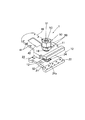
以下、本発明に係わる鳥害防止装置の好ましい実施の形態を図1から図11に基づいて説明する。本実施の形態は、自己支持型の架空ケーブルのうち電力ケーブルと支持線とが一体化された架空ケーブルに取り付けられる鳥害防止装置を例にして説明する。先ず、架空ケーブルの概略について説明する。架空ケーブルKは、図1(側面図)に示すように、図示しない電柱間に張架されたメッセンジャーワイヤーW(以下、「ワイヤーW」と記す。)と、ワイヤーWの下方位置にワイヤーWに沿って延びる電力ケーブルDと、ワイヤーW及び電力ケーブルDを一体に緊縛するバインド線Bとを有してなる。電力ケーブルDは、図2(断面図)に示すように、縦断面視において三角状に配置された3本の電線Dsからなり、各電線Dsの外径はワイヤーWのそれよりも大径である。バインド線Bは、ワイヤーWとこの下方に配置された電力ケーブルDを緊縛してワイヤーW及び電力ケーブルDを一体化している。なお、電力ケーブルDは、1本、2本、又は4本以上の電線Dsから構成されてもよい。 A preferred embodiment of a bird harm prevention apparatus according to the present invention will be described below with reference to FIGS. In the present embodiment, a bird harm prevention apparatus attached to an aerial cable in which a power cable and a support line are integrated among self-supporting aerial cables will be described as an example. First, an outline of the overhead cable will be described. As shown in FIG. 1 (side view), the overhead cable K includes a messenger wire W (hereinafter referred to as “wire W”) stretched between utility poles (not shown), and a wire W at a position below the wire W. The power cable D extends along the wire W and the bind wire B that binds the power cable D together. As shown in FIG. 2 (sectional view), the power cable D is composed of three electric wires Ds arranged in a triangular shape in a longitudinal sectional view, and the outer diameter of each electric wire Ds is larger than that of the wire W. is there. The bind line B binds the wire W and the power cable D disposed below the wire W and integrates the wire W and the power cable D. Note that the power cable D may be composed of one, two, or four or more electric wires Ds.
このように構成された架空ケーブルKに取り付けられる鳥害防止装置1は、図1に示すように、ワイヤーWに取り付けられて使用される。鳥害防止装置1は、図3(側面図)及び4(斜視図)に示すように、ワイヤーWを把持する把持部10と、防鳥用の細線Sを架空ケーブルKの上方に離隔して架設する細線架設部40と、把持部10を締結する締結部50とを有してなる。
The bird harm prevention apparatus 1 attached to the aerial cable K configured in this way is used by being attached to a wire W as shown in FIG. As shown in FIGS. 3 (side view) and 4 (perspective view), the bird damage prevention apparatus 1 separates the gripping
把持部10は一対の把持部材11、21によって構成される。把持部材11、21は板状であり、他方の把持部材11の基端部には厚さ方向の一方側に面してワイヤーWを把持するための第1押圧面部12が形成されている。第1押圧面部12は、図5(b)(側面図)に示すように、所定の曲率半径を有して円弧状に湾曲する。第1押圧面部12上には複数の突起部13が突出して設けられている。図5(a)(側面図)に示すように、把持部材11の中央部であって第1押圧面部12より上方に所定距離Aを有した位置には、円形状に開口する第1貫通孔14が形成されている。第1貫通孔14は、後述するボルトの軸部が挿通可能であれば、円形に限るものではなく、多角形状、矩形状等でもよい。把持部材11の幅方向の一方側の端部には、第1落下防止用孔15が形成されている。また把持部材11の両側部には把持部材11の厚さ方向一方側に突出して他方の把持部材21と係合する係合突出部16が形成されている。なお、第1落下防止用孔15は、把持部材11の幅方向の一方側端部の他に、他方側端部に形成されてもよい。
The
一方の把持部材21は、図6(b)(正面図)に示すように、基端側端部に前述した第1押圧面部12と対向配置されてワイヤーWを把持するための第2押圧面部22が形成されている。第2押圧面部22は第1押圧面部12と略同一の曲率半径を有して円弧状に湾曲し、第2押圧面部22上には複数の突起部13が形成されている。第1押圧面部12及び第2押圧面部22の曲率半径は、径の大きなワイヤーWを挟持可能な大きさを有している。このため、図5(a)に示す第1押圧面部12及び第2押圧面部22によって径の大きなワイヤーWが挟み込まれると、これらの面部がワイヤーWの両側面に密着してワイヤーWを確実に挟持することができる。また、複数の突起部13がワイヤーWの表面に噛み込んで、ワイヤーWに対する一対の把持部材11、21の滑りを防止している。
As shown in FIG. 6B (front view), one gripping
一方の把持部材21の先端側には、第2押圧面部22と同一方向に延びるとともに第2押圧面部22と同一方向に面する第3押圧面部23が形成されている。第3押圧面部23は、第1押圧面部12と対向配置されて第2押圧面部22の曲率半径よりも小さなそれを有して円弧状に湾曲する。第3押圧面部23の曲率半径は、径の小さなワイヤーWを挟持可能な大きさを有している。つまり、図5(a)に示す第1押圧面部12に対して第3押圧面部23を対向配置すると、径の小さなワイヤーWを挟持することができる。なお、第3押圧面部23上には、第2押圧面部22と同様に複数の突起部13が形成されている。
A third
このため、一方の把持部材21は、第2押圧面部22及び第3押圧面部23を図5(a)に示す第1押圧面部12に対向配置可能にするため、他方の把持部材11に対して回動可能に構成されている。即ち、図8(b)(斜視図)に示すように、一方の把持部材21は、この中央部に第2貫通孔24が形成され、この第2貫通孔24に挿通されたボルト51の軸部53を回動支点として回動可能である。そして、第2押圧面部22及び第3押圧面部23は、図6(b)に示す第2貫通孔24から所定距離Aを有した位置に配置されている。このため、図5(a)に示す第1貫通孔14及び第2貫通孔24にボルト51の軸部53を挿通した状態で他方の把持部材21を回動させると、図8(a)(斜視図)に示すように、第2押圧面部22を第1押圧面部12に対向配置して径の大きなワイヤーWbを把持することができ、また図8(c)(斜視図)に示すように、第3押圧面部23を第1押圧面部12に対向配置して径の小さなワイヤーWsを把持することができる。なお、一方の把持部材21に形成された押圧面部は2つに限るものではなく、3個以上の押圧面部を第2貫通孔24に対して放射状に配置して形成してもよい。
For this reason, one gripping
第2貫通孔24は、図4(斜視図)に示すように、矩形状に形成され、ボルト51に設けられた角柱状のストッパ部52と係合してボルト51の回動を規制するように構成されている。即ち、第2貫通孔24は方形状に配置された4つのストッパ面24aを有して形成され、第2貫通孔24にストッパ部52を挿着してボルト51を回動すると、ストッパ部52が4つのストッパ面24aの少なくとも何れかに当接してボルト51の回動を規制する。このため、一対の把持部材11、21をボルト51及びこれに螺合するナット55で締結する際に、ボルト51を一方の把持部材21に固定した状態でナット55を回すことができ、締結操作を容易にすることができる。なお、第2貫通孔24は多角形状でもよい。
As shown in FIG. 4 (perspective view), the second through
再び図6(b)に示すように、一方の把持部材21の幅方向の両側には、第2落下防止用孔25が形成されている。これらの第2落下防止用孔25は、第2押圧面部22又は第3押圧面部23を図5(a)に示す第1押圧面部12に対向配置すると、前述した第1落下防止用孔15と連通するように配置されている。従って、図3に示す架空ケーブルKに掛け回されたひも部材60を連通した第2落下防止用孔25及び第1落下防止用孔15に通して繋ぐことで、鳥害防止装置1が架空ケーブルKから落下する事態を未然に防止することができる。なお、ひも部材60は、折り曲げ自在な材料、例えば、金属、プラスチック、ガラス繊維等の材料で形成される。
As shown in FIG. 6B again, second fall prevention holes 25 are formed on both sides in the width direction of one gripping
このように構成された一対の把持部材11、21を締結するためのボルト51は、図7(a)(側面図)及び(b)(正面図)に示すように、雄ねじ部53aを形成した軸部53と軸部53の基端側に形成された前述したストッパ部52と、ストッパ部52の基端側に形成された頭部54とを有して形成される。頭部54は直方体状に形成され、作業者によるボルト51の把持を容易にしている。
As shown in FIGS. 7A (side view) and (b) (front view), the
さて、一対の把持部材11、21のうち他方の把持部材11の先端部には、図5(a)(正面図)に示すように、防鳥用の細線を架空ケーブルの上方に離隔して架設する細線架設部40が形成されている。細線架設部40は把持部材11の先端部から延び、その幅方向の両端部には、異なる高さ位置に設けられて細線を巻き付けるための複数の固定溝41が形成されている。また細線架設部40の中央部には風を通すための風孔42が設けられている。さらに細線架設部40の先端部は、高さ方向に突出して円弧状に形成されるとともに、図5(b)(側面図)に示すように、先端側に進むに従って漸次厚さが薄くなるように形成されている。このため、鳥が細線架設部40の先端部に止まり難くしている。
Now, as shown in FIG. 5A (front view), at the tip of the other gripping
次に、前述した鳥害防止装置1の装着方法について説明する。先ず、図4に示すように、一対の把持部材11、21を対向配置し、ボルト51の先端部を第2貫通孔24から挿入して、ボルト51を第2貫通孔24及び第1貫通孔14に挿通する。そして、一対の把持部材11、21がボルト51の軸方向に移動できるように第1貫通孔14から突出したボルト51の軸部53にナット55を螺合する。そして、この未締結状態の鳥害防止装置1を必要な数、用意する。そして、架空ケーブルのワイヤーの径に応じて第2押圧面部22又は第3押圧面部23を選択し、この選択した押圧面部が第1押圧面部12に対向配置されるように一方の把持部材21をボルト51に対して回動させる。そして、ボルト51のストッパ部52を一方の把持部材21の第2貫通孔24に係合させてボルト51の回動を規制し、一対の把持部材11、21を互いに接近移動させて第1押圧面部12と選択した押圧面部間に図1に示すワイヤーWを挟み込み、ナット55を回して一対の把持部材11、21を締結して鳥害防止装置1をワイヤーWに仮止めする。なお、ナット55を回す際に、ボルト51は一方の把持部材21に固定されて回動が規制されているので、ボルト51がナット55とともに共回りすることはない。
Next, a method for mounting the above-described bird damage prevention apparatus 1 will be described. First, as shown in FIG. 4, the pair of gripping
このようにして、図1に示すように、ワイヤーWに対して、所定間隔を有して鳥害防止装置1を順次仮止めしていく。そして、仮止めされた鳥害防止装置1のうち最端部に配置されている鳥害防止装置1の細線架設部40の固定溝41に細線Sを巻き付けて固定し、細線Sを固定した鳥害防止装置1に隣接する他の鳥害防止装置1'の複数の固定溝41のうち鳥の種類に応じて選択した固定溝41に細線Sを順次巻き付けながら張設し、この状態で細線Sに張力を与えながら仮止め状態の鳥害防止装置1、1'を本止めする。その結果、鳥害防止装置1、1'が自己支持型の架設ケーブルKに装着されるとともに、細線Sが架設ケーブルKの上方位置に架設される。このため、鳥が細線Sの存在によって架設ケーブルKとまることができなくなり、鳥害を防止することができる。
In this way, as shown in FIG. 1, the bird harm prevention apparatus 1 is temporarily temporarily attached to the wire W at a predetermined interval. And the thin wire S is wound around the fixing
なお、前述した実施の形態では、3本の電線Dsを束ねた架設ケーブルKを例にしたが、架設ケーブルKは、図9(a)に示すように、ワイヤーWの回りを1本の電線Dsが捻転しながら延びて架設されたものや、図9(b)に示すように、ワイヤーWの下方位置にワイヤーWに沿って電線Dsを配置し、ワイヤーWと電線Dsを被覆材70(例えば、合成樹脂材料製の被覆膜)で覆って繋いだものでもよい。 In the above-described embodiment, the installation cable K in which the three electric wires Ds are bundled is taken as an example. However, the installation cable K has one electric wire around the wire W as shown in FIG. As shown in FIG. 9B, the electric wire Ds is arranged along the wire W at the lower position of the wire W, and the wire W and the electric wire Ds are covered with the covering material 70 ( For example, it may be covered with a synthetic resin material covering film).
このように、鳥害防止装置1は、一対の把持部材11、21を有してなる把持部10と細線架設部40とを備え、一方の把持部材21が他方の把持部材11に対して回動可能であり、一方の把持部材21にワイヤーWの径に応じて選択可能な2つ押圧面部22、23を設けることにより、断面形状が三角状の自己支持型の架空ケーブルKにおいて、鳥害防止装置1を、電線Dsの外径に拘らずに架空ケーブルKに装着することができる。
As described above, the bird damage prevention apparatus 1 includes the
次に、本発明に係わる鳥害防止構造について説明する。なお、鳥害防止構造については、前述した鳥害防止装置1と同一態様部分については同一符号を附してその説明を省略する。 Next, the bird damage prevention structure according to the present invention will be described. In addition, about a bird damage prevention structure, about the same aspect part as the bird damage prevention apparatus 1 mentioned above, the same code | symbol is attached | subjected and the description is abbreviate | omitted.
鳥害防止構造は、図10(側面図)に示すように、電線DsとワイヤーWとが一体的に取り付けられて捩られた自己支持型の架設ケーブルK'に前述した鳥害防止装置1と中間支持具80とを取り付けたものである。この架設ケーブルK'のワイヤーWは、電線Dsの頂部のみならず電線Dsの側部や底部に延びた状態で配置されている。従って、電線Dsの頂部に延びるワイヤーWに前述した鳥害防止装置1を取り付けることはできるが、電線Dsの側部や底部に延びるワイヤーWに前述した鳥害防止装置1を取り付けると、細線Sを架設ケーブルKの上方位置に架設することができなくなる。そこで、架設ケーブルKの延びる方向に離隔して配置されて電線Dsの頂部に延びるワイヤーWに2つの鳥害防止装置1、1'を取り付け、これらの2つの鳥害防止装置1,1'間に延びるワイヤーWのうち電線Dsの底部(側部でもよい)に延びるワイヤーWに接触する部分の電線Dsの頂部に中間支持具80を取り付ける。
As shown in FIG. 10 (side view), the bird damage prevention structure includes the above-described bird damage prevention apparatus 1 mounted on a self-supporting erection cable K ′ in which an electric wire Ds and a wire W are integrally attached and twisted. An
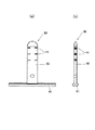
中間支持具80は、図11(a)(正面図)及び(b)(側面図)に示すように、電線に取り付けられる基部81と、基部81の中央上部から上方へ突出する細線架設部82とを有してなる。基部81の底側は凹状に形成されて電線との密着性を良くしている。基部は粘着テープやひも部材等を介して架設ケーブルに取り付けられる。
As shown in FIGS. 11A (front view) and (b) (side view), the
このように鳥害防止構造を構成することで、図10に示すように、架空ケーブルKの頂部に延びるワイヤーWに取り付けられた2つの鳥害防止装置1、1'間に掛け渡された細線Sの長さが長い場合であっても、中間支持具80をこの細線Sの中間部に取り付けると、掛け渡された細線Sの撓みを防止することができる。その結果、鳥害防止装置1を取り付け可能な架空ケーブルの対象範囲が拡大して、鳥害防止装置1の使用可能範囲を広げることができる。なお、自己支持型の架空ケーブルは、図10に示したものに限るものではなく、ワイヤーWと電線Dsを同一の被覆部材で覆ってなるケーブルを捻転したものや、電線Dsの周面にワイヤーWを螺旋状に巻き付けながら電線Dsに沿って延ばしてワイヤーWと電線Dsとを一体的に取り付けてなるケーブルでもよい。
By configuring the bird damage prevention structure in this way, as shown in FIG. 10, a thin wire spanned between the two bird damage prevention apparatuses 1 and 1 ′ attached to the wire W extending to the top of the overhead cable K. Even when the length of S is long, if the
1 鳥害防止装置
10 把持部(把持手段)
11、21 把持部材
12 第1押圧面部(対向押圧面部)
14 第1貫通孔(貫通孔)
15 第1落下防止用孔(落下防止用孔)
22 第2押圧面部(押圧面部)
23 第3押圧面部(押圧面部)
24 第2貫通孔(貫通孔)
25 第2落下防止用孔(落下防止用孔)
40 細線架設部(細線架設手段)
41 固定溝
42 風孔
50 締結部(締結手段)
51 ボルト
52 ストッパ部
55 ナット
60 ひも部材
80 中間支持具(中間支持手段)
Ds 電線
K 架空ケーブル
S 細線
W メッセンジャーワイヤー(支持線)
1 Bird
11, 21
14 First through hole (through hole)
15 First fall prevention hole (fall prevention hole)
22 2nd press surface part (press surface part)
23 3rd pressing surface part (pressing surface part)
24 Second through hole (through hole)
25 Second fall prevention hole (fall prevention hole)
40 Thin wire erection part (Thin wire erection means)
41 fixing
51
Ds Electric wire K Aerial cable S Thin wire W Messenger wire (support wire)
Claims (8)
前記支持線を把持する把持手段と、
防鳥用の細線を前記架空ケーブルの上方に離隔して架設する細線架設手段とを備え、
前記把持手段を一対の把持部材によって形成し、
前記一対の把持部材のうちの一方の把持部材に、径の異なる支持線に対応する曲率半径を有した押圧面部を複数設け、
取り付けようとする支持線の径に合わせて押圧面部を選択できるように、前記一方の把持部材を他方の把持部材に対して回動可能に設け、
前記他方の把持部材に、前記一方の把持部材の選択された押圧面部に対向して前記取り付けようとする支持線を把持可能な対向押圧面部を設けたことを特徴とする鳥害防止装置。 A bird damage prevention device for preventing bird damage from an aerial cable in which electric wires for communication or power supply are integrally attached to a support line stretched between power poles,
Gripping means for gripping the support wire;
A thin wire laying means for laying a bird proof thin wire separately above the overhead cable;
The gripping means is formed by a pair of gripping members,
A plurality of pressing surface portions having a radius of curvature corresponding to support wires having different diameters are provided on one gripping member of the pair of gripping members ,
The one gripping member is provided so as to be rotatable with respect to the other gripping member so that the pressing surface portion can be selected according to the diameter of the support wire to be attached,
A bird damage prevention device , wherein the other gripping member is provided with an opposing pressing surface portion capable of gripping the support line to be attached to face the selected pressing surface portion of the one gripping member .
前記一方の把持部材及び前記他方の把持部材に設けられた貫通孔の少なくともいずれかに、前記ボルトに設けられたストッパ部と係合して前記ボルトの回動を規制するストッパ面を設けたことを特徴とする請求項2に記載の鳥害防止装置。 The fastening means has a bolt inserted through a through hole provided in the one gripping member and the other gripping member, and a nut screwed into the bolt,
At least one of the through-holes provided in the one gripping member and the other gripping member is provided with a stopper surface that engages with a stopper portion provided on the bolt and restricts the rotation of the bolt. The bird damage prevention apparatus according to claim 2, wherein:
防鳥用の細線を前記架空ケーブルの上方に離隔して架設する請求項1から7のいずれかに記載の鳥害防止装置を、前記支持線のうちの前記架空ケーブルの頂部に延びる支持線に取り付け、
前記架空ケーブルの延びる方向に離隔して取り付けられた2つの前記鳥害防止装置間に延びる支持線のうち、前記電線の側部又は底部に延びる支持線が接する電線部分の頂部に、前記2つの鳥害防止装置間に掛け渡された細線を支持する中間支持手段を取り付けたことを特徴とする鳥害防止構造。 An aerial cable in which a support line for supporting an electric wire for communication or power supply extends spirally along the peripheral surface of the electric wire, and the support wire and the electric wire are integrally attached and are spanned between power poles A bird damage prevention structure for preventing bird damage from
The bird damage prevention apparatus according to any one of claims 1 to 7 , wherein a bird-proof thin wire is installed separately above the aerial cable. attachment,
Wherein one of the two said support wire extending between cockles prevention device mounted spaced apart in the direction of extension of the aerial cable, the top portion of the wire portion supporting line contacts extending in the side or bottom of the electric wire, the two A bird damage prevention structure characterized in that an intermediate support means for supporting a fine wire spanned between bird damage prevention apparatuses is attached.
Priority Applications (1)
| Application Number | Priority Date | Filing Date | Title |
|---|---|---|---|
| JP2004283488A JP3894330B2 (en) | 2004-09-29 | 2004-09-29 | Bird damage prevention device and bird damage prevention structure |
Applications Claiming Priority (1)
| Application Number | Priority Date | Filing Date | Title |
|---|---|---|---|
| JP2004283488A JP3894330B2 (en) | 2004-09-29 | 2004-09-29 | Bird damage prevention device and bird damage prevention structure |
Publications (3)
| Publication Number | Publication Date |
|---|---|
| JP2005000178A JP2005000178A (en) | 2005-01-06 |
| JP2005000178A5 JP2005000178A5 (en) | 2006-07-27 |
| JP3894330B2 true JP3894330B2 (en) | 2007-03-22 |
Family
ID=34101570
Family Applications (1)
| Application Number | Title | Priority Date | Filing Date |
|---|---|---|---|
| JP2004283488A Active JP3894330B2 (en) | 2004-09-29 | 2004-09-29 | Bird damage prevention device and bird damage prevention structure |
Country Status (1)
| Country | Link |
|---|---|
| JP (1) | JP3894330B2 (en) |
Families Citing this family (3)
| Publication number | Priority date | Publication date | Assignee | Title |
|---|---|---|---|---|
| JP2006296312A (en) * | 2005-04-21 | 2006-11-02 | Tokyo Electric Power Co Inc:The | Bird damage preventing device for cable |
| KR101040134B1 (en) | 2011-02-01 | 2011-06-09 | 주식회사 유원기업 | Units for bird nesting prevention |
| JP2019122344A (en) * | 2018-01-19 | 2019-07-25 | ヨツギ株式会社 | Bird damage prevention tool |
-
2004
- 2004-09-29 JP JP2004283488A patent/JP3894330B2/en active Active
Also Published As
| Publication number | Publication date |
|---|---|
| JP2005000178A (en) | 2005-01-06 |
Similar Documents
| Publication | Publication Date | Title |
|---|---|---|
| US20210041042A1 (en) | Hanger for mounting multiple cables | |
| US8648254B2 (en) | Device and method for stringing overhead cable | |
| JP6533970B2 (en) | Overhead wire holding device | |
| US8820715B2 (en) | Wire stringing angle clamp | |
| KR100638637B1 (en) | Band cable | |
| JP4757243B2 (en) | Fall prevention tool | |
| JP3894330B2 (en) | Bird damage prevention device and bird damage prevention structure | |
| CN115064986A (en) | Anti-slip paying-off tackle | |
| KR200393275Y1 (en) | wire harness fixing clip structure | |
| JP4979541B2 (en) | Cable fixing method | |
| JP2012191916A (en) | Device for preventing vine winding for utility pole support wire | |
| US11817817B2 (en) | Cable hanger | |
| JP2007262768A (en) | Curing device on bend, and curing method on bend, using the same | |
| JP2007159537A (en) | Apparatus for preventing nesting | |
| JP2010025302A (en) | Fall prevention tool | |
| US20140367623A1 (en) | Wire Stringing Angle Clamp | |
| US20150102180A1 (en) | Post Support | |
| WO2015034873A1 (en) | Impact-absorbing wire and cable fixture, system, and related methods | |
| EP1602573A3 (en) | Cable winding conversion device | |
| JP4953651B2 (en) | Pin insulator and electric wire support method using the same | |
| CN212107780U (en) | A mounting bracket for monitoring facilities on transmission tower | |
| JP4699442B2 (en) | Optical fiber cable extra length support | |
| JP4939951B2 (en) | Laying cable support | |
| JP2017189055A (en) | Branching wire fitting | |
| US9093827B2 (en) | Wire pulling device |
Legal Events
| Date | Code | Title | Description |
|---|---|---|---|
| A521 | Written amendment |
Free format text: JAPANESE INTERMEDIATE CODE: A523 Effective date: 20060607 |
|
| A621 | Written request for application examination |
Free format text: JAPANESE INTERMEDIATE CODE: A621 Effective date: 20060607 |
|
| A131 | Notification of reasons for refusal |
Free format text: JAPANESE INTERMEDIATE CODE: A131 Effective date: 20060912 |
|
| A521 | Written amendment |
Free format text: JAPANESE INTERMEDIATE CODE: A523 Effective date: 20061106 |
|
| TRDD | Decision of grant or rejection written | ||
| A01 | Written decision to grant a patent or to grant a registration (utility model) |
Free format text: JAPANESE INTERMEDIATE CODE: A01 Effective date: 20061201 |
|
| A61 | First payment of annual fees (during grant procedure) |
Free format text: JAPANESE INTERMEDIATE CODE: A61 Effective date: 20061205 |
|
| R150 | Certificate of patent or registration of utility model |
Free format text: JAPANESE INTERMEDIATE CODE: R150 Ref document number: 3894330 Country of ref document: JP Free format text: JAPANESE INTERMEDIATE CODE: R150 |
|
| FPAY | Renewal fee payment (event date is renewal date of database) |
Free format text: PAYMENT UNTIL: 20091222 Year of fee payment: 3 |
|
| FPAY | Renewal fee payment (event date is renewal date of database) |
Free format text: PAYMENT UNTIL: 20101222 Year of fee payment: 4 |
|
| R250 | Receipt of annual fees |
Free format text: JAPANESE INTERMEDIATE CODE: R250 |
|
| FPAY | Renewal fee payment (event date is renewal date of database) |
Free format text: PAYMENT UNTIL: 20101222 Year of fee payment: 4 |
|
| FPAY | Renewal fee payment (event date is renewal date of database) |
Free format text: PAYMENT UNTIL: 20111222 Year of fee payment: 5 |
|
| R250 | Receipt of annual fees |
Free format text: JAPANESE INTERMEDIATE CODE: R250 |
|
| FPAY | Renewal fee payment (event date is renewal date of database) |
Free format text: PAYMENT UNTIL: 20111222 Year of fee payment: 5 |
|
| FPAY | Renewal fee payment (event date is renewal date of database) |
Free format text: PAYMENT UNTIL: 20121222 Year of fee payment: 6 |
|
| R250 | Receipt of annual fees |
Free format text: JAPANESE INTERMEDIATE CODE: R250 |
|
| FPAY | Renewal fee payment (event date is renewal date of database) |
Free format text: PAYMENT UNTIL: 20121222 Year of fee payment: 6 |
|
| FPAY | Renewal fee payment (event date is renewal date of database) |
Free format text: PAYMENT UNTIL: 20131222 Year of fee payment: 7 |
|
| R250 | Receipt of annual fees |
Free format text: JAPANESE INTERMEDIATE CODE: R250 |
|
| R250 | Receipt of annual fees |
Free format text: JAPANESE INTERMEDIATE CODE: R250 |
|
| R250 | Receipt of annual fees |
Free format text: JAPANESE INTERMEDIATE CODE: R250 |
|
| R250 | Receipt of annual fees |
Free format text: JAPANESE INTERMEDIATE CODE: R250 |
|
| R250 | Receipt of annual fees |
Free format text: JAPANESE INTERMEDIATE CODE: R250 |
|
| R250 | Receipt of annual fees |
Free format text: JAPANESE INTERMEDIATE CODE: R250 |
|
| R250 | Receipt of annual fees |
Free format text: JAPANESE INTERMEDIATE CODE: R250 |
|
| R250 | Receipt of annual fees |
Free format text: JAPANESE INTERMEDIATE CODE: R250 |
|
| R250 | Receipt of annual fees |
Free format text: JAPANESE INTERMEDIATE CODE: R250 |