JP7621620B2 - Microwave heating unit and carbon fiber manufacturing method using the same - Google Patents
Microwave heating unit and carbon fiber manufacturing method using the same Download PDFInfo
- Publication number
- JP7621620B2 JP7621620B2 JP2022579550A JP2022579550A JP7621620B2 JP 7621620 B2 JP7621620 B2 JP 7621620B2 JP 2022579550 A JP2022579550 A JP 2022579550A JP 2022579550 A JP2022579550 A JP 2022579550A JP 7621620 B2 JP7621620 B2 JP 7621620B2
- Authority
- JP
- Japan
- Prior art keywords
- fiber
- furnace body
- heated
- waveguide
- heating unit
- Prior art date
- Legal status (The legal status is an assumption and is not a legal conclusion. Google has not performed a legal analysis and makes no representation as to the accuracy of the status listed.)
- Active
Links
Images


Classifications
-
- D—TEXTILES; PAPER
- D01—NATURAL OR MAN-MADE THREADS OR FIBRES; SPINNING
- D01F—CHEMICAL FEATURES IN THE MANUFACTURE OF ARTIFICIAL FILAMENTS, THREADS, FIBRES, BRISTLES OR RIBBONS; APPARATUS SPECIALLY ADAPTED FOR THE MANUFACTURE OF CARBON FILAMENTS
- D01F9/00—Artificial filaments or the like of other substances; Manufacture thereof; Apparatus specially adapted for the manufacture of carbon filaments
- D01F9/08—Artificial filaments or the like of other substances; Manufacture thereof; Apparatus specially adapted for the manufacture of carbon filaments of inorganic material
- D01F9/12—Carbon filaments; Apparatus specially adapted for the manufacture thereof
- D01F9/14—Carbon filaments; Apparatus specially adapted for the manufacture thereof by decomposition of organic filaments
- D01F9/32—Apparatus therefor
-
- D—TEXTILES; PAPER
- D01—NATURAL OR MAN-MADE THREADS OR FIBRES; SPINNING
- D01F—CHEMICAL FEATURES IN THE MANUFACTURE OF ARTIFICIAL FILAMENTS, THREADS, FIBRES, BRISTLES OR RIBBONS; APPARATUS SPECIALLY ADAPTED FOR THE MANUFACTURE OF CARBON FILAMENTS
- D01F9/00—Artificial filaments or the like of other substances; Manufacture thereof; Apparatus specially adapted for the manufacture of carbon filaments
- D01F9/08—Artificial filaments or the like of other substances; Manufacture thereof; Apparatus specially adapted for the manufacture of carbon filaments of inorganic material
- D01F9/12—Carbon filaments; Apparatus specially adapted for the manufacture thereof
-
- D—TEXTILES; PAPER
- D02—YARNS; MECHANICAL FINISHING OF YARNS OR ROPES; WARPING OR BEAMING
- D02J—FINISHING OR DRESSING OF FILAMENTS, YARNS, THREADS, CORDS, ROPES OR THE LIKE
- D02J13/00—Heating or cooling the yarn, thread, cord, rope, or the like, not specific to any one of the processes provided for in this subclass
-
- F—MECHANICAL ENGINEERING; LIGHTING; HEATING; WEAPONS; BLASTING
- F27—FURNACES; KILNS; OVENS; RETORTS
- F27B—FURNACES, KILNS, OVENS OR RETORTS IN GENERAL; OPEN SINTERING OR LIKE APPARATUS
- F27B9/00—Furnaces through which the charge is moved mechanically, e.g. of tunnel type; Similar furnaces in which the charge moves by gravity
- F27B9/28—Furnaces through which the charge is moved mechanically, e.g. of tunnel type; Similar furnaces in which the charge moves by gravity for treating continuous lengths of work
-
- F—MECHANICAL ENGINEERING; LIGHTING; HEATING; WEAPONS; BLASTING
- F27—FURNACES; KILNS; OVENS; RETORTS
- F27B—FURNACES, KILNS, OVENS OR RETORTS IN GENERAL; OPEN SINTERING OR LIKE APPARATUS
- F27B9/00—Furnaces through which the charge is moved mechanically, e.g. of tunnel type; Similar furnaces in which the charge moves by gravity
- F27B9/30—Details, accessories or equipment specially adapted for furnaces of these types
- F27B9/36—Arrangements of heating devices
-
- F—MECHANICAL ENGINEERING; LIGHTING; HEATING; WEAPONS; BLASTING
- F27—FURNACES; KILNS; OVENS; RETORTS
- F27D—DETAILS OR ACCESSORIES OF FURNACES, KILNS, OVENS OR RETORTS, IN SO FAR AS THEY ARE OF KINDS OCCURRING IN MORE THAN ONE KIND OF FURNACE
- F27D11/00—Arrangement of elements for electric heating in or on furnaces
- F27D11/12—Arrangement of elements for electric heating in or on furnaces with electromagnetic fields acting directly on the material being heated
-
- F—MECHANICAL ENGINEERING; LIGHTING; HEATING; WEAPONS; BLASTING
- F27—FURNACES; KILNS; OVENS; RETORTS
- F27D—DETAILS OR ACCESSORIES OF FURNACES, KILNS, OVENS OR RETORTS, IN SO FAR AS THEY ARE OF KINDS OCCURRING IN MORE THAN ONE KIND OF FURNACE
- F27D99/00—Subject matter not provided for in other groups of this subclass
- F27D99/0001—Heating elements or systems
- F27D99/0006—Electric heating elements or system
-
- H—ELECTRICITY
- H05—ELECTRIC TECHNIQUES NOT OTHERWISE PROVIDED FOR
- H05B—ELECTRIC HEATING; ELECTRIC LIGHT SOURCES NOT OTHERWISE PROVIDED FOR; CIRCUIT ARRANGEMENTS FOR ELECTRIC LIGHT SOURCES, IN GENERAL
- H05B6/00—Heating by electric, magnetic or electromagnetic fields
- H05B6/64—Heating using microwaves
- H05B6/78—Arrangements for continuous movement of material
-
- H—ELECTRICITY
- H05—ELECTRIC TECHNIQUES NOT OTHERWISE PROVIDED FOR
- H05B—ELECTRIC HEATING; ELECTRIC LIGHT SOURCES NOT OTHERWISE PROVIDED FOR; CIRCUIT ARRANGEMENTS FOR ELECTRIC LIGHT SOURCES, IN GENERAL
- H05B6/00—Heating by electric, magnetic or electromagnetic fields
- H05B6/64—Heating using microwaves
- H05B6/80—Apparatus for specific applications
-
- D—TEXTILES; PAPER
- D01—NATURAL OR MAN-MADE THREADS OR FIBRES; SPINNING
- D01F—CHEMICAL FEATURES IN THE MANUFACTURE OF ARTIFICIAL FILAMENTS, THREADS, FIBRES, BRISTLES OR RIBBONS; APPARATUS SPECIALLY ADAPTED FOR THE MANUFACTURE OF CARBON FILAMENTS
- D01F9/00—Artificial filaments or the like of other substances; Manufacture thereof; Apparatus specially adapted for the manufacture of carbon filaments
- D01F9/08—Artificial filaments or the like of other substances; Manufacture thereof; Apparatus specially adapted for the manufacture of carbon filaments of inorganic material
- D01F9/12—Carbon filaments; Apparatus specially adapted for the manufacture thereof
- D01F9/14—Carbon filaments; Apparatus specially adapted for the manufacture thereof by decomposition of organic filaments
- D01F9/32—Apparatus therefor
- D01F9/328—Apparatus therefor for manufacturing filaments from polyaddition, polycondensation, or polymerisation products
-
- D—TEXTILES; PAPER
- D10—INDEXING SCHEME ASSOCIATED WITH SUBLASSES OF SECTION D, RELATING TO TEXTILES
- D10B—INDEXING SCHEME ASSOCIATED WITH SUBLASSES OF SECTION D, RELATING TO TEXTILES
- D10B2101/00—Inorganic fibres
- D10B2101/10—Inorganic fibres based on non-oxides other than metals
- D10B2101/12—Carbon; Pitch
-
- F—MECHANICAL ENGINEERING; LIGHTING; HEATING; WEAPONS; BLASTING
- F27—FURNACES; KILNS; OVENS; RETORTS
- F27D—DETAILS OR ACCESSORIES OF FURNACES, KILNS, OVENS OR RETORTS, IN SO FAR AS THEY ARE OF KINDS OCCURRING IN MORE THAN ONE KIND OF FURNACE
- F27D3/00—Charging; Discharging; Manipulation of charge
- F27D2003/0034—Means for moving, conveying, transporting the charge in the furnace or in the charging facilities
- F27D2003/0057—Fast-outlet or inlet means
-
- F—MECHANICAL ENGINEERING; LIGHTING; HEATING; WEAPONS; BLASTING
- F27—FURNACES; KILNS; OVENS; RETORTS
- F27D—DETAILS OR ACCESSORIES OF FURNACES, KILNS, OVENS OR RETORTS, IN SO FAR AS THEY ARE OF KINDS OCCURRING IN MORE THAN ONE KIND OF FURNACE
- F27D99/00—Subject matter not provided for in other groups of this subclass
- F27D99/0001—Heating elements or systems
- F27D99/0006—Electric heating elements or system
- F27D2099/0028—Microwave heating
Landscapes
- Engineering & Computer Science (AREA)
- Mechanical Engineering (AREA)
- General Engineering & Computer Science (AREA)
- Textile Engineering (AREA)
- Physics & Mathematics (AREA)
- Electromagnetism (AREA)
- General Chemical & Material Sciences (AREA)
- Chemical & Material Sciences (AREA)
- Chemical Kinetics & Catalysis (AREA)
- Manufacturing & Machinery (AREA)
- Inorganic Fibers (AREA)
- Constitution Of High-Frequency Heating (AREA)
- Furnace Details (AREA)
Description
本発明は、マイクロ波を照射して被加熱連続繊維を加熱するマイクロ波加熱ユニット、及びこれを用いる炭素繊維製造方法に関する。The present invention relates to a microwave heating unit that irradiates microwaves to heat continuous fibers to be heated, and a method for producing carbon fibers using the same.
炭素繊維は、他の繊維と比較して優れた比強度及び比弾性率を有しており、その軽量性及び優れた機械的特性を利用して、樹脂と複合化する補強繊維等として広く工業的に利用されている。 Carbon fiber has superior specific strength and specific elastic modulus compared to other fibers, and its light weight and excellent mechanical properties mean that it is widely used industrially as a reinforcing fiber to be combined with resin.
従来、炭素繊維は次のように製造されている。先ず、前駆体繊維を加熱空気中230~260℃で30~100分間加熱することにより耐炎化処理される。この耐炎化処理により、アクリル系繊維の環化反応を生じさせ、酸素結合量を増加させて耐炎化繊維を得る。この耐炎化繊維は、例えば、窒素雰囲気下、300~800℃の焼成炉を用いて温度勾配をかけながら炭素化される(第一炭素化処理)。次いで、窒素雰囲気下で800~2100℃の焼成炉を用いて温度勾配をかけながらさらに炭素化される(第二炭素化処理)。このように、炭素繊維は加熱された焼成炉内で、耐炎化繊維をその外部から加熱することによって製造されている。Conventionally, carbon fibers are manufactured as follows. First, the precursor fibers are flame-retarded by heating them in heated air at 230-260°C for 30-100 minutes. This flame-retardant treatment causes a cyclization reaction of the acrylic fibers, increasing the amount of oxygen bonded to obtain flame-retardant fibers. The flame-retardant fibers are carbonized, for example, in a nitrogen atmosphere using a baking furnace at 300-800°C while applying a temperature gradient (first carbonization treatment). Next, the fibers are further carbonized in a nitrogen atmosphere using a baking furnace at 800-2100°C while applying a temperature gradient (second carbonization treatment). In this way, carbon fibers are manufactured by heating the flame-retardant fibers from the outside in a heated baking furnace.
上記のように製造する場合、被炭素化繊維内部の炭素化が不十分になることを避けるために、時間をかけて徐々に昇温しなければならない。また、外部から加熱を行う焼成炉は、炉体や焼成雰囲気のような被炭素化繊維以外のものも加熱されるため、熱効率が低い。When manufacturing as described above, the temperature must be raised gradually over time to avoid insufficient carbonization inside the carbonized fiber. In addition, sintering furnaces that heat from the outside have low thermal efficiency because they also heat things other than the fiber to be carbonized, such as the furnace body and the sintering atmosphere.
近年、マイクロ波を照射することにより被炭素化繊維を加熱して炭素繊維を製造することが試みられている。マイクロ波による物質の加熱は、その内部から加熱される。そのため、マイクロ波を用いて被炭素化繊維を加熱する場合、繊維表面及び繊維内部における炭素化を均一に行うことが可能であり、炭素繊維の製造時間の短縮が期待される。 In recent years, attempts have been made to produce carbon fibers by heating fibers to be carbonized by irradiating them with microwaves. When materials are heated by microwaves, they are heated from the inside. Therefore, when the fibers to be carbonized are heated using microwaves, it is possible to uniformly carbonize the fiber surface and inside the fibers, which is expected to shorten the time required to produce carbon fibers.
従来、マイクロ波を用いて炭素繊維を製造する方法としては、特許文献1が知られている。特許文献1にはマイクロ波を用いる炭素繊維の製造方法が記載されている。
また、特許文献2には、被加熱物を加熱炉に対して斜めに搬送することにより、食品等の加熱斑を抑制するマイクロ波加熱装置が記載されている。
A conventional method for producing carbon fibers using microwaves is disclosed in Patent Document 1. Patent Document 1 describes a method for producing carbon fibers using microwaves.
Furthermore, Patent Document 2 describes a microwave heating device that prevents uneven heating of food or the like by conveying the object to be heated at an angle to a heating furnace.
しかし、炭素繊維の製造工程においては、被加熱繊維が誘電体から半導体、次いで導電体へと連続的に変化する。特に、マイクロ波を用いる炭素繊維の製造工程においては、被加熱繊維の性質が瞬時に変化する。即ち、被加熱繊維の誘電率が変化することにより、適した加熱条件が瞬時に変化する。そのため、従来のマイクロ波加熱ユニットを用いて被加熱繊維を加熱する場合、炉内の電磁気学的エネルギーの性質から不安定反応が起こりやすく、被加熱繊維を著しく損傷させて工程安定性が低下するとともに、得られる繊維の品質が著しく低下する場合があった。However, in the carbon fiber manufacturing process, the heated fiber continuously changes from a dielectric to a semiconductor and then to a conductor. In particular, in the carbon fiber manufacturing process using microwaves, the properties of the heated fiber change instantaneously. That is, the suitable heating conditions change instantaneously as the dielectric constant of the heated fiber changes. Therefore, when the heated fiber is heated using a conventional microwave heating unit, unstable reactions are likely to occur due to the nature of the electromagnetic energy in the furnace, which can significantly damage the heated fiber, reducing process stability and significantly reducing the quality of the obtained fiber.
本発明の課題は、マイクロ波を照射することによって被加熱繊維を加熱するマイクロ波加熱ユニットであって、被加熱繊維の誘電率が変化しても安定して加熱することができる小型のマイクロ波加熱ユニットを提供することである。また、本発明の他の課題は、該マイクロ波加熱ユニットを用いて被加熱繊維を炭素化する炭素繊維の製造方法を提供することである。 The object of the present invention is to provide a small microwave heating unit that heats a fiber to be heated by irradiating microwaves, and that can stably heat the fiber to be heated even if the dielectric constant of the fiber to be heated changes. Another object of the present invention is to provide a method for producing carbon fiber that carbonizes the fiber to be heated using the microwave heating unit.
本発明者らは、炉体の軸心に対して被加熱連続繊維を斜めに走行させることにより、上記課題を解決できることを見出した。即ち、炉体内に生じる電磁界分布は、導波管の所定箇所で極大電界強度となるところ、被加熱連続繊維を導波管の管軸に対して斜めに走行させることにより、極大電界強度付近で被加熱連続繊維を加熱するとともに、当該加熱によって誘電率が変化した被加熱連続繊維を速やかに極大電界強度付近から退避させることにより、被加熱連続繊維が半導体や導電体に変化したことによって生じる電界反射を抑制して工程安定性を高めることができることを見出した。
また、誘電体である被加熱連続繊維が半導体や導電体に変化した後に加熱する場合、マイクロ波の電界成分を利用する加熱では、放電による切断を生じやすく、加熱が不安定になるとともに被加熱連続繊維の品質を著しく低下させるところ、磁界成分を利用する加熱により、係る問題を解決できることを見出した。
The present inventors have found that the above problem can be solved by running the heated continuous fiber obliquely relative to the axis of the furnace body. That is, the electromagnetic field distribution generated in the furnace body has a maximum electric field intensity at a predetermined location of the waveguide, and by running the heated continuous fiber obliquely relative to the axis of the waveguide, the heated continuous fiber is heated near the maximum electric field intensity, and the heated continuous fiber whose dielectric constant has changed due to the heating is quickly removed from the vicinity of the maximum electric field intensity, thereby suppressing electric field reflection caused by the heated continuous fiber changing into a semiconductor or conductor, thereby improving process stability.
In addition, when the heated continuous fiber, which is a dielectric, is converted into a semiconductor or conductor and then heated, heating using the electric field component of microwaves is prone to causing breakage due to discharge, making the heating unstable and significantly degrading the quality of the heated continuous fiber; however, it has been found that such problems can be solved by heating using the magnetic field component.
また、本発明者らは、筒状の炉体内に、マイクロ波を透過させる筒状の保温管を配設し、この中に被加熱連続繊維を走行させてマイクロ波を照射することに想到した。この保温管は、高温時にはマイクロ波を吸収して自ら発熱するため、被加熱連続繊維を高温で保温して炭素化速度を飛躍的に向上させることができることを見出した。
これらの知見に基づき、本発明を完成するに至った。
The inventors also came up with the idea of arranging a cylindrical heat-retaining tube that transmits microwaves inside a cylindrical furnace body, and irradiating the heated continuous fiber with microwaves while the heated continuous fiber runs through the tube. This heat-retaining tube absorbs microwaves at high temperatures and generates heat by itself, and they found that the heated continuous fiber can be kept at a high temperature and the carbonization speed can be dramatically improved.
Based on these findings, the present invention has been completed.
上記課題を解決する本発明は以下に記載するとおりである。The present invention, which solves the above problems, is as described below.
〔1〕 導波管の管壁に繊維導入口(103、203、303)及び繊維導出口(105、205、305)が形成されて成る炉体(100、101、201、301、401、501)と、
前記導波管内にマイクロ波を導入するマイクロ波発振器(11)と、
を含んで成るマイクロ波加熱ユニット(1000、1000a、1000b、1000c、1001、1002、1003、1004)であって、
前記被加熱連続繊維(150、250、350、450、550、251、351、451、551)が前記導波管の管軸に対して角度θ°の傾斜を有してその内部を走行するように構成されており、前記角度θ°が0<θ<90であり、
前記繊維導出口が前記導波管の終端部以外の部分に形成されていることを特徴とするマイクロ波加熱ユニット。
[1] A furnace body (100, 101, 201, 301, 401, 501) having a fiber inlet (103, 203, 303) and a fiber outlet (105, 205, 305) formed in a wall of a waveguide;
A microwave oscillator (11) for introducing microwaves into the waveguide;
A microwave heating unit (1000, 1000a, 1000b, 1000c, 1001, 1002, 1003, 1004) comprising:
The heated continuous fiber (150, 250, 350, 450, 550, 251, 351, 451, 551) is configured to run inside the waveguide at an angle θ° with respect to the axis of the waveguide, the angle θ° being 0<θ<90;
13. A microwave heating unit, comprising: a waveguide having a fiber outlet formed at a portion other than a terminal end of the waveguide;
〔2〕 前記角度θ°が10<θ<60である〔1〕に記載のマイクロ波加熱ユニット。[2] A microwave heating unit as described in [1], wherein the angle θ° is 10<θ<60.
上記〔1〕及び〔2〕のマイクロ波加熱ユニットは、導波管を炉体とし、その内部を走行する被加熱連続繊維に常圧下でマイクロ波を照射するマイクロ波加熱ユニットであり、被加熱繊維を導波管の管軸に対して斜めに走行させることを特徴とする。The microwave heating units of [1] and [2] above are microwave heating units that use a waveguide as a furnace body and irradiate microwaves under normal pressure to the heated continuous fiber running inside it, and are characterized in that the heated fiber runs obliquely with respect to the axis of the waveguide.
〔3〕 前記導波管が方形導波管であり、前記導波管の短辺管壁にそれぞれ前記繊維導入口と前記繊維導出口とが設けられている〔1〕に記載のマイクロ波加熱ユニット。[3] A microwave heating unit as described in [1], wherein the waveguide is a rectangular waveguide, and the fiber inlet and the fiber outlet are provided on each of the short side walls of the waveguide.
〔4〕 前記導波管を貫通するとともに、前記繊維導入口と前記繊維導出口とを接続する保温管(107、207、307)を更に有して成り、前記保温管の内部を前記被加熱連続繊維が走行するように構成されている〔1〕に記載のマイクロ波加熱ユニット。[4] The microwave heating unit described in [1] further comprises an insulated tube (107, 207, 307) that penetrates the waveguide and connects the fiber inlet and the fiber outlet, and is configured so that the heated continuous fiber runs inside the insulated tube.
〔5〕 前記保温管の材質がセラミックである〔1〕に記載のマイクロ波加熱ユニット。[5] A microwave heating unit as described in [1], in which the material of the heat-insulating tube is ceramic.
上記〔4〕及び〔5〕のマイクロ波加熱ユニットは、被加熱連続繊維の走行部の外周がセラミック製の保温管で覆われている。 In the microwave heating units of [4] and [5] above, the outer circumference of the running section of the heated continuous fiber is covered with a ceramic heat-insulating tube.
〔6〕 〔1〕乃至〔5〕に記載のマイクロ波加熱ユニットを用いて被加熱連続繊維を走行させながら加熱する中間炭素繊維乃至炭素繊維の製造方法であって、炭素含有率が66質量%未満の被加熱連続繊維を加熱して中間炭素繊維乃至炭素繊維を得る工程を含むことを特徴とする中間炭素繊維乃至炭素繊維の製造方法。[6] A method for producing intermediate carbon fibers or carbon fibers, which uses a microwave heating unit described in [1] to [5] to heat a heated continuous fiber while it is running, and which is characterized in that it includes a step of heating a heated continuous fiber having a carbon content of less than 66 mass% to obtain intermediate carbon fibers or carbon fibers.
〔7〕 〔6〕に記載の炭素繊維の製造方法であって、さらに〔1〕乃至〔5〕に記載のマイクロ波加熱ユニットを用いて導波管内の極大磁界部分に被加熱連続繊維を走行させながら加熱する炭素繊維の製造方法。[7] A method for producing carbon fibers as described in [6], further comprising the step of heating a continuous fiber to be heated while it is running through a maximum magnetic field portion in a waveguide using a microwave heating unit as described in [1] to [5].
上記〔6〕及び〔7〕に記載の炭素繊維製造方法は、炭素繊維製造工程の少なくとも一部に〔1〕乃至〔5〕に記載のマイクロ波加熱ユニットを用いる炭素繊維の製造方法である。
The carbon fiber production methods described in [6] and [7] above are methods for producing carbon fibers that use the microwave heating units described in [1] to [5] in at least a part of the carbon fiber production process.
本発明のマイクロ波加熱ユニットは、被加熱連続繊維が炉体の軸心に対して斜めに走行する。そのため、炉体内の極大電界部分で加熱されて性状(誘電率)が変化した被加熱連続繊維を速やかに極大電界部分から退避できる。その結果、炉内で半導体乃至導電体となった繊維による電界反射が生じ難くなり、工程安定性を高くすることができる。
また、炉体として方形導波管を用い、繊維導入口及び繊維導出口を方形導波管のH面に装荷する場合は、炉体の幅を小さくすることができ、装置をコンパクトにできる。
さらに、保温管を用いる場合には、被加熱連続繊維を高温で保持することができるため、炭素化の効率を高くできる。
In the microwave heating unit of the present invention, the heated continuous fiber runs obliquely to the axis of the furnace body. Therefore, the heated continuous fiber, whose properties (dielectric constant) have changed due to being heated in the maximum electric field part in the furnace body, can be quickly removed from the maximum electric field part. As a result, electric field reflection due to the fiber that has become a semiconductor or conductor in the furnace is less likely to occur, and the process stability can be improved.
Furthermore, when a rectangular waveguide is used as the furnace body and the fiber inlet and fiber outlet are mounted on the H-face of the rectangular waveguide, the width of the furnace body can be reduced, allowing the device to be made compact.
Furthermore, when a heat-retaining tube is used, the heated continuous fiber can be maintained at a high temperature, thereby increasing the efficiency of carbonization.
以下、図面を参照しながら本発明のマイクロ波加熱ユニット及びこれを用いる炭素繊維の製造方法について詳細に説明する。
なお、本発明において、炉体のH面とは方形導波管の短辺管壁を意味し、E面とは方形導波管の長辺管壁を意味する。
本発明において、誘電体、半導体及び導電体とは、明確な数値によって区別されるものではなく、被加熱連続繊維が加熱される前の状態が誘電体であり、完全に加熱された状態が導電体であり、その中間の状態が半導体であることを意味する。即ち、被加熱連続繊維が炭素繊維前駆体である場合、炭素繊維前駆体(炭素含有率が66~72質量%)が誘電体であり、炭素繊維乃至黒鉛化繊維が導電体(炭素含有率が90質量%以上)であり、その中間にある状態が半導体であることを意味する。
Hereinafter, the microwave heating unit of the present invention and the method for producing carbon fiber using the same will be described in detail with reference to the drawings.
In the present invention, the H-plane of the furnace body means the short side wall of the rectangular waveguide, and the E-plane means the long side wall of the rectangular waveguide.
In the present invention, the terms "dielectric,""semiconductor," and "conductor" are not distinguished by clear numerical values, but rather mean that the heated continuous fiber is in a dielectric state before it is heated, is in a conductor state when it is completely heated, and is in an intermediate state where it is a semiconductor. That is, when the heated continuous fiber is a carbon fiber precursor, the carbon fiber precursor (carbon content of 66 to 72% by mass) is a dielectric, the carbon fiber or graphitized fiber is a conductor (carbon content of 90% by mass or more), and is in an intermediate state where it is a semiconductor.
(1) マイクロ波加熱ユニット
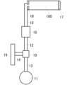
図1は、本発明のマイクロ波加熱ユニットの一構成例を示す説明図である。図1中、11はマイクロ波発振器であり、マイクロ波発振器11には、接続導波管12の一端が接続されており、接続導波管12の他端は炉体100に接続されている。この接続導波管12には、マイクロ波発振器11側から順にサーキュレータ13及び整合器15が介装されている。サーキュレータ13には、接続導波管14の一端が接続されており、接続導波管14の他端にはダミーロード19が接続されている。このとき、マイクロ波の炉体100への流入量と炉体100からの流出量を調整するための機構であるアイリス16と定在波を形成するための短絡板17とを導波管の各端部にそれぞれ設けることもできる。
(1) Microwave heating unit Fig. 1 is an explanatory diagram showing one example of the configuration of the microwave heating unit of the present invention. In Fig. 1, 11 is a microwave oscillator, and one end of a connecting
(2) 炉体
本発明のマイクロ波加熱ユニットの炉体100は、円筒導波管又は方形導波管から構成されている。導波管内にマイクロ波が導入されることにより、導波管内には、TE(Transverse Electric)モードの電磁界分布が形成される。TEモードとは、導波管内に伝送されるマイクロ波の方向に直交する電界成分を有する伝送モ-ドをいう。炉体100内に定在波を生じさせることにより、炉体100内には電界成分が極大になる場所と磁界成分が極大となる場所とが異なる位置で存在する。そのため、被加熱連続繊維を炉体内に走行させることによって、主として電界成分による加熱(以下、「電界加熱」ともいう)、及び主として磁界成分による加熱(以下、「磁界加熱」ともいう)をそれぞれ行うことができる。
(2) Furnace The
(2-1) 円筒導波管を用いる炉体
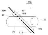
図2は、本発明のマイクロ波加熱ユニットの炉体の一構成例を示す説明図である。
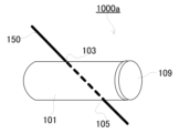
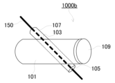
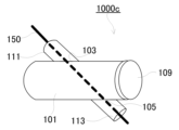
図2中、1000はマイクロ波加熱ユニットであり、101は少なくとも一端が閉塞した円筒導波管から構成される炉体である。炉体101の外周には、繊維導入口103と繊維導出口105とがそれぞれ形成されている。炉体101には、炉体101の内部を管軸に対して斜めに貫通するとともに、繊維導入口103と繊維導出口105とを接続する保温管107が設けられていてもよい。保温管107は、その内部に被加熱連続繊維150が搬送されるように構成されている。炉体101の閉塞した内端部には短絡板109が配設されている。繊維導入口103及び繊維導出口105には、炉体101からの電磁波漏えいを防ぐために、それぞれ金属スリーブ111及び113を設けることができる。
なお、図14は、金属スリーブ及び保温管を設けない場合のマイクロ波加熱ユニットの炉体1000aである。図15は、金属スリーブを設けない場合のマイクロ波加熱ユニットの炉体1000bである。図16は、保温管を設けない場合のマイクロ波加熱ユニットの炉体1000cである。図2と同じ構成には同じ参照符号を付してその説明を省略する。
(2-1) Furnace Body Using a Cylindrical Waveguide FIG. 2 is an explanatory diagram showing one example of the configuration of the furnace body of the microwave heating unit of the present invention.
In Fig. 2, 1000 is a microwave heating unit, and 101 is a furnace body composed of a cylindrical waveguide with at least one end closed. A
Fig. 14 shows a
次に、このマイクロ波加熱ユニット1000の動作について説明する。図2中、150は被加熱連続繊維であり、不図示の繊維搬送手段によって、保温管107の内部を通って繊維導入口103から炉体101内部に連続的に搬入される。マイクロ波発振器11が発振するマイクロ波は、接続導波管12内を通って、さらにアイリス16を通って炉体101内に導入される。炉体101内に到達したマイクロ波は、炉体101の閉塞した内端部(終端部)に配設された短絡板109で反射して整合器15を経由してサーキュレータ13に到達する。反射されたマイクロ波(以下、「反射波」ともいう)は、サーキュレータ13で方向が変えられ、接続導波管14を通ってダミーロード19で吸収される。このとき、整合器15を用いて整合器15と短絡板109との間で整合がとられ、炉体101内に定在波が生じる。この定在波によって、炉体101内には電界成分が極大になる場所(極大電界部分)と、磁界成分が極大になる場所(極大磁界部分)とが、それぞれ異なる位置に形成される。この定在波によって被加熱連続繊維150は加熱される。なお、本発明のマイクロ波加熱ユニット1000は、被加熱連続繊維150の走行方向は管軸に対して斜め方向であり、垂直でも平行でもない。そのため、被加熱連続繊維150は、極大電界部分又は極大磁界部分のみを走行することはない。また、このとき、炉体101内は常圧であり、且つ不図示の不活性ガス供給手段によって不活性雰囲気となっている。加熱された被加熱連続繊維150は、不図示の繊維搬送手段により、繊維導出口105を通って炉体101外に搬出される。被加熱連続繊維を繊維導入口103から炉体101内に連続的に搬入し、炉体101内で被加熱連続繊維にマイクロ波を照射して加熱し、繊維導出口105から連続的に搬出することにより、連続的に被加熱連続繊維150を加熱することができる。Next, the operation of the
炉体101の管軸と保温管107の管軸とのなす角θ°は、0<θ<90であり、10<θ<60であることが好ましく、15<θ<55であることがより好ましい。また、被加熱連続繊維150は、炉体の終端部以外の部分から炉体外に搬出されるように構成されている。即ち、繊維導出口105は炉体101の管軸に沿う外周面に形成されている。炉体101の管軸と保温管107の管軸とを斜交させることにより、被加熱連続繊維の走行方向を管軸に対して傾斜させ、被加熱連続繊維が極大電界部分又は極大磁界部分を走行しつつも、該極大電界部分又は該極大磁界部分のみを走行することを防ぐことができる。その結果、後述するように、工程安定性を向上させることができる。なお、炉体101の管軸と被加熱連続繊維150とのなす角θ°は、0<θ<90であり、10<θ<60であることが好ましく、15<θ<55であることがより好ましい。The angle θ° between the tube axis of the
(2-2) 方形導波管を用いる炉体
(a) H面装荷炉
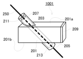
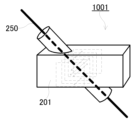
図3は、本発明のマイクロ波加熱ユニットの炉体の一構成例を示す説明図である。図3中、1001はマイクロ波加熱ユニットであり、201は少なくとも一端が閉塞した方形導波管から構成される炉体である。炉体201の短辺管壁である2つのH面201a、201bには、繊維導入口203と繊維導出口205とがそれぞれ形成されている。炉体201には、炉体201の内部を斜めに貫通するとともに、繊維導入口203と繊維導出口205とを接続する保温管207が設けられていてもよい。保温管207は、その内部に被加熱連続繊維250が搬送されるように構成されている。炉体201の閉塞した内端部には短絡板209が配設されている。繊維導入口203及び繊維導出口205には炉体201からの電磁波漏えいを防ぐために、それぞれ金属スリーブ211及び213を設けることもできる。なお、円筒導波管を用いる場合と同様に、方形導波管を用いる場合であっても、保温管及び/又は金属スリーブは省略可能である。
(2-2) Furnace using a rectangular waveguide (a) H-plane loading furnace FIG. 3 is an explanatory diagram showing one example of the configuration of the furnace of the microwave heating unit of the present invention. In FIG. 3, 1001 is a microwave heating unit, and 201 is a furnace composed of a rectangular waveguide with at least one end closed. A
次に、このマイクロ波加熱ユニット1001の動作について説明する。図3中、250は被加熱連続繊維であり、不図示の繊維搬送手段によって、保温管207の内部を通って繊維導入口203から炉体201内部に連続的に搬入される。マイクロ波発振器11が発振するマイクロ波は、接続導波管12内を通って、さらにアイリス16を通って炉体201内に導入される。炉体201内に到達したマイクロ波は、炉体201の閉塞した内端部(終端部)に配設された短絡板209で反射して整合器15を経由してサーキュレータ13に到達する。反射波は、サーキュレータ13で方向が変えられ、接続導波管14を通ってダミーロード19で吸収される。このとき、整合器15を用いて整合器15と短絡板209との間で整合がとられ、炉体201内に定在波が生じる。この定在波によって、炉体201内には電界成分が極大になる場所(極大電界部分)と、磁界成分が極大になる場所(極大磁界部分)とが、それぞれ異なる位置に形成される。この定在波によって被加熱連続繊維250は加熱される。なお、本発明のマイクロ波加熱ユニット1001は、被加熱連続繊維250の走行方向は管軸に対して斜め方向であり、垂直でも平行でもない。そのため、被加熱連続繊維250は、極大電界部分又は極大磁界部分のみを走行することはない。また、このとき、炉体201内は常圧であり、且つ不図示の不活性ガス供給手段によって不活性雰囲気となっている。加熱された被加熱連続繊維250は、不図示の繊維搬送手段により、繊維導出口205を通って炉体201外に搬出される。被加熱連続繊維を繊維導入口203から炉体201内に連続的に搬入し、炉体201内で被加熱連続繊維にマイクロ波を照射して加熱し、繊維導出口205から連続的に搬出することにより、連続的に被加熱連続繊維250を加熱することができる。Next, the operation of the
炉体201の管軸と保温管207の管軸とのなす角θ°は、0<θ<90であり、10<θ<60であることが好ましく、15<θ<55であることがより好ましい。また、被加熱連続繊維250は、炉体の終端部以外の部分から炉体外に搬出されるように構成されている。即ち、繊維導出口205は炉体201のH面201bに形成されている。炉体201の管軸と保温管207の管軸とを斜交させることにより、被加熱連続繊維の走行方向を管軸に対して傾斜させ、被加熱連続繊維が極大電界部分又は極大磁界部分を走行しつつも、該極大電界部分又は該極大磁界部分のみを走行することを防ぐことができる。その結果、後述するように、工程安定性を向上させることができる。なお、炉体201の管軸と被加熱連続繊維250とのなす角θ°は、0<θ<90であり、10<θ<60であることが好ましく、15<θ<55であることがより好ましい。The angle θ° between the tube axis of the
本発明においては、機幅及びトウピッチを小さくできるH面装荷炉であることが好ましい。In the present invention, it is preferable to use an H-face loading furnace which allows the machine width and tow pitch to be small.
(b) E面装荷炉
図4は、本発明のマイクロ波加熱ユニットの炉体の他の構成例を示す説明図である。図4中、1002はマイクロ波加熱ユニットであり、301は少なくとも一端が閉塞した方形導波管から構成される炉体である。炉体301の長辺管壁である2つのE面301a、301bには、繊維導入口303と繊維導出口305とがそれぞれ形成されている。炉体301には、炉体301の内部を斜めに貫通するとともに、繊維導入口303と繊維導出口305とを接続する保温管307が設けられている。保温管307は、その内部に被加熱連続繊維350が搬送されるように構成されている。炉体301の閉塞した内端部には短絡板309が配設されている。繊維導入口303及び繊維導出口305には炉体301からの電磁波漏えいを防ぐために、それぞれ金属スリーブ311及び313を設けることもできる。
(b) E-surface loading furnace Figure 4 is an explanatory diagram showing another example of the configuration of the furnace body of the microwave heating unit of the present invention. In Figure 4, 1002 is a microwave heating unit, and 301 is a furnace body composed of a rectangular waveguide with at least one end closed. A
このマイクロ波加熱ユニット1002の動作については、前述のマイクロ波加熱ユニット1001と同様であるため省略する。
The operation of this
(3) 電界加熱
以下、電界加熱により、誘電体である炭素繊維前駆体を加熱する炉体の構成について説明する。
(3) Electric Field Heating Hereinafter, the configuration of a furnace body that heats the carbon fiber precursor, which is a dielectric material, by electric field heating will be described.
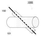
図5は、図2のマイクロ波加熱ユニットの炉体101内における電磁界分布の一例を示す説明図である。この炉体101は、被加熱連続繊維150(炭素繊維前駆体)の走行部分に極大電界部分を含んで構成されている。図5には、炉体101内における電界分布を実線で、磁界分布を破線で模式的に記載してある。この炉体101は、炉体101内を走行する被加熱連続繊維150(炭素繊維前駆体)に直交する電界成分が形成され、これにより被加熱連続繊維150(炭素繊維前駆体)は加熱される。この時、被加熱連続繊維150(炭素繊維前駆体)の走行方向は、炉体101の管軸に対して斜交しているため、炉体101内における極大電界部分のみを通るのではなく、弱電界部分も通る。即ち、繊維導入口103から炉体101内に搬入された被加熱連続繊維150(炭素繊維前駆体)は、炉体101内における弱電界部分、極大電界部分、弱電界部分を順次通って、繊維導出口105から炉体101外に搬出されるように構成されている。極大電界部分で加熱されることにより、炭素繊維前駆体が半導体乃至導電体に変化した後に、極大電界部分から被加熱繊維が速やかに退避される。そのため、炉体内におけるマイクロ波の照射状態を安定させることができる。なお、この時、繊維導入口を炉体101の上側に設けることにより、炉体から生じる熱が炉体上側に排熱されて、被加熱連続繊維150(炭素繊維前駆体)を予熱できるので好ましい。
Figure 5 is an explanatory diagram showing an example of the electromagnetic field distribution in the
図6は、図3のマイクロ波加熱ユニットの炉体201内における電磁界分布を示す説明図である。炉体201はH面装荷炉である。このH面装荷炉は、被加熱連続繊維250(炭素繊維前駆体)の走行部分に極大電界部分を含んで構成されている。図6には、炉体201内における電界分布を実線で、磁界分布を破線で模式的に記載してある。この炉体は、炉体201内を走行する被加熱連続繊維250(炭素繊維前駆体)に直交する電界成分が形成され、これにより被加熱連続繊維250(炭素繊維前駆体)は加熱される。この時、被加熱連続繊維250(炭素繊維前駆体)の走行方向は、炉体201の管軸に対して斜交しているため、炉体201内における極大電界部分のみを通るのではなく、弱電界部分も通る。即ち、繊維導入口203から炉体201内に搬入された被加熱連続繊維250(炭素繊維前駆体)は、炉体201内における弱電界部分、極大電界部分、弱電界部分を順次通って、繊維導出口205から炉体201外に搬出されるように構成されている。極大電界部分で加熱されることにより、炭素繊維前駆体が半導体乃至導電体に変化した後に、極大電界部分から被加熱繊維が速やかに退避される。そのため、炉体内におけるマイクロ波の照射状態を安定させることができる。なお、この時、繊維導入口を炉体201の上側に設けることにより、炉体から生じる熱が炉体上側に排熱されて、被加熱連続繊維250(炭素繊維前駆体)を予熱できるので好ましい。
Figure 6 is an explanatory diagram showing the electromagnetic field distribution in the
図7は、図4のマイクロ波加熱ユニットの炉体301内における電磁界分布を示す説明図である。炉体301はE面装荷炉である。このE面装荷炉は、被加熱連続繊維350(炭素繊維前駆体)の走行部分に極大電界部分を含んで構成されている。図7には、炉体301内における電界分布を実線で、磁界分布を破線で模式的に記載してある。この炉体は、炉体301内を走行する被加熱連続繊維350(炭素繊維前駆体)の長手方向に一部の電界成分が形成され、これにより被加熱連続繊維350(炭素繊維前駆体)は効率的に加熱される。この時、被加熱連続繊維350(炭素繊維前駆体)の走行方向は、炉体301の管軸に対して斜交しているため、炉体301内における極大電界部分のみを通るのではなく、弱電界部分も通る。即ち、繊維導入口303から炉体301内に搬入された被加熱連続繊維350(炭素繊維前駆体)は、炉体301内における弱電界部分、極大電界部分、弱電界部分を順次通って、繊維導出口305から炉体301外に搬出されるように構成されている。被加熱連続繊維350(炭素繊維前駆体)の長手方向の電界成分を含む極大電界部分で加熱されることにより、炭素繊維前駆体が半導体乃至導電体に変化した後に、極大電界部分から被加熱繊維が速やかに退避される。そのため、炉体内におけるマイクロ波の照射状態を安定させることができる。
Figure 7 is an explanatory diagram showing the electromagnetic field distribution in the
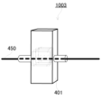
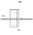
図8は、マイクロ波加熱ユニット1003の炉体401内における電磁界分布を示す説明図である。この炉体401はH面装荷炉である。このH面装荷炉においては、被加熱連続繊維450(炭素繊維前駆体)は極大電界部分を走行するように構成されている。図8には、炉体401内における電界分布を破線で、磁界分布を実線で模式的に記載してある。この炉体は、炉体401の長辺管壁に垂直な電界成分が形成され、これにより被加熱連続繊維450(炭素繊維前駆体)は加熱される。即ち、繊維導入口から炉体401内に搬入された被加熱連続繊維450(炭素繊維前駆体)は、炉体401内における極大電界部分を通って、繊維導出口から炉体401外に搬出されるように構成されている。
Figure 8 is an explanatory diagram showing the electromagnetic field distribution in the
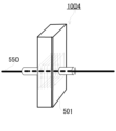
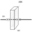
図9は、マイクロ波加熱ユニット1004の炉体501内における電磁界分布を示す説明図である。この炉体501はE面装荷炉である。このE面装荷炉においては、被加熱連続繊維550(炭素繊維前駆体)は極大電界部分を走行するように構成されている。図9には、炉体501内における電界分布を破線で、磁界分布を実線で模式的に記載してある。この炉体は、炉体501の長辺管壁に平行であり、且つ走行する被加熱連続繊維550(炭素繊維前駆体)に平行な電界成分が形成され、これにより被加熱連続繊維550(炭素繊維前駆体)は加熱される。即ち、繊維導入口から炉体501内に搬入された被加熱連続繊維550(炭素繊維前駆体)は、炉体501内における極大電界部分を通って、繊維導出口から炉体501外に搬出されるように構成されている。
FIG. 9 is an explanatory diagram showing the electromagnetic field distribution in the
(4) 磁界加熱
以下、磁界加熱により、半導体乃至導電体である被加熱連続繊維を加熱する炉体の構成について説明する。
(4) Magnetic Field Heating Hereinafter, the configuration of the furnace body that heats the heated continuous fiber, which is a semiconductor or a conductor, by magnetic field heating will be described.
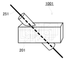
図10は、図3のマイクロ波加熱ユニットの炉体201内における電磁界分布を示す説明図である。この炉体201はH面装荷炉である。このH面装荷炉は、被加熱連続繊維251の走行部分に極大磁界発生部分を含んで構成されている。図10には、炉体201内における電界分布を破線で、磁界分布を実線で模式的に記載してある。この炉体は、炉体201の長辺管壁に平行な磁界成分が形成され、これにより被加熱連続繊維251は加熱される。この時、被加熱連続繊維251の走行方向は、炉体201の管軸に対して斜交しているため、炉体201内における極大磁界部分のみを通るのではなく、弱磁界部分も通る。即ち、繊維導入口203から炉体201内に搬入された被加熱連続繊維251は、炉体201内における弱磁界部分、極大磁界部分、弱磁界部分を順次通って、繊維導出口205から炉体201外に搬出されるように構成されている。極大磁界部分で加熱され、極大電界部分を避けることにより、炉体内におけるマイクロ波の照射状態を安定させることができる。弱磁界部分、極大磁界部分、弱磁界部分を順次通ることから、被加熱連続繊維の温度が低下しやすい。そのため、後述の保温管を用いることが好ましい。
Figure 10 is an explanatory diagram showing the electromagnetic field distribution within the
図11は、図4のマイクロ波加熱ユニットの炉体301内における電磁界分布を示す説明図である。この炉体301はE面装荷炉である。このE面装荷炉は、被加熱連続繊維351の走行部分に極大磁界部分を含んで構成されている。図11には、炉体301内における電界分布を破線で、磁界分布を実線で模式的に記載してある。この炉体は、炉体301の長辺管壁に平行な磁界成分が形成され、これにより被加熱連続繊維351は加熱される。この時、被加熱連続繊維351の走行方向は、炉体301の管軸に対して斜交しているため、炉体301内における極大磁界部分のみを通るのではなく、弱磁界部分も通る。即ち、繊維導入口303から炉体301内に搬入された被加熱連続繊維351は、炉体301内における弱磁界部分、極大磁界部分、弱磁界部分を順次通って、繊維導出口305から炉体301外に搬出されるように構成されている。極大磁界部分で加熱され、且つ極大電界部分を避けることにより、炉体内におけるマイクロ波の照射状態を安定させることができる。弱磁界部分、極大磁界部分、弱磁界部分を順次通ることから、被加熱連続繊維の温度が低下しやすい。そのため、後述の保温管を用いることが好ましい。
Figure 11 is an explanatory diagram showing the electromagnetic field distribution within the
図12は、マイクロ波加熱ユニット1003の炉体401内における電磁界分布を示す説明図である。この炉体401はH面装荷炉である。このH面装荷炉においては、被加熱連続繊維は極大磁界部分を走行するように構成されている。図12には、炉体401内における電界分布を破線で、磁界分布を実線で模式的に記載してある。この炉体は、炉体401の長辺管壁に平行な磁界成分が形成され、これにより被加熱連続繊維451は加熱される。即ち、繊維導入口から炉体401内に搬入された被加熱連続繊維451は、炉体401内における極大電界部分を避けるとともに、極大磁界部分を通って、繊維導出口から炉体401外に搬出されるように構成されている。
Figure 12 is an explanatory diagram showing the electromagnetic field distribution in the
図13は、マイクロ波加熱ユニット1004の炉体501内における電磁界分布を示す説明図である。この炉体501はE面装荷炉である。このE面装荷炉においては、被加熱連続繊維は極大磁界部分を走行するように構成されている。図13には、炉体501内における電界分布を破線で、磁界分布を実線で模式的に記載してある。この炉体は、炉体501の長辺管壁に平行であり、且つ走行する被加熱連続繊維に直交する磁界成分が形成され、これにより被加熱連続繊維551は加熱される。即ち、繊維導入口から炉体501内に搬入された炭素繊維前駆体551は、炉体501内における極大電界部分を避けるとともに、極大磁界部分を通って、繊維導出口から炉体501外に搬出されるように構成されている。
FIG. 13 is an explanatory diagram showing the electromagnetic field distribution in the
(5) 保温管
本発明のマイクロ波加熱ユニットは保温管を有していることが好ましい。保温管は、炉体を貫通するとともに、繊維導入口と繊維導出口とを接続するように炉体内に挿入され、その内部に被加熱連続繊維が走行可能に構成されている。保温管は、被加熱連続繊維の加熱に起因して生じる輻射熱を保温管が遮断して放熱を抑制することにより、保温管内が高温に保持される。保温管内は常圧であり、且つ不図示の不活性ガス供給手段によって不活性雰囲気となっている。
(5) Heat-retaining tube The microwave heating unit of the present invention preferably has a heat-retaining tube. The heat-retaining tube is inserted into the furnace body so as to penetrate the furnace body and connect the fiber inlet and the fiber outlet, and is configured so that the heated continuous fiber can run inside the heat-retaining tube. The heat-retaining tube blocks radiant heat generated by heating the heated continuous fiber and suppresses heat dissipation, thereby maintaining a high temperature inside the heat-retaining tube. The inside of the heat-retaining tube is at normal pressure, and an inert atmosphere is created by an inert gas supply means (not shown).
保温管107、207、307は円筒状であることが好ましい。保温管107、207、307の内径は、特に限定されないが、一般的には8~55mmである。保温管107、207、307の外径は、特に限定されないが、一般的には10~60mmである。保温管107、207、307の長さは、特に限定されないが、一般的には100~2500mmである。また、保温管107、207、307の材質は、マイクロ波を透過する材料であることが必要であり、マイクロ波の透過率は常温(25℃)で90~100%であることが好ましく、95~100%であることがより好ましい。このような材料としては、石英やアルミナ等のセラミックが例示される。これらの材料のマイクロ波の透過率は石英が100%、アルミナが99.9%である。セラミックのマイクロ波の透過率は組成によって異なり、シリカ41%-アルミナ55%の場合は99.9%であるが、マイクロ波の透過率が前記範囲内であれば組成がこの組み合わせに限定されるものではない。セラミックとしては、アルミナ、シリカアルミナ、チタニア、ジルコニア、マグネシア、カルシア等の金属酸化物や、窒化ケイ素、窒化アルミニウム、窒化チタン等の金属窒化物、その他の化合物を含有するものでも良い。特に、アルミナ又はシリカアルミナは、高温時において、マイクロ波を一部吸収して発熱するサセプターとして機能するので好ましい。保温管107、207、307の両端には、マイクロ波の漏洩を防ぐためにマイクロ波を吸収する材料が配されていても良い。
The heat-insulating
炉体として用いる導波管の形状は、導波管内にTEモードの電磁界分布を形成することができれば特に限定されない。一般的には、導波管の長さは、500~1500mmが好ましい。また、方形導波管の管軸に直交する断面の開口部は、長辺が105~115mmであることが好ましく、短辺は50~60mmであることが好ましい。導波管の材質は特に限定されないが、一般にステンレス、鉄、銅、アルミニウム等の金属製である。 The shape of the waveguide used as the furnace body is not particularly limited as long as it can form a TE mode electromagnetic field distribution within the waveguide. In general, the length of the waveguide is preferably 500 to 1500 mm. Furthermore, the opening of the cross section perpendicular to the tube axis of the rectangular waveguide preferably has a long side of 105 to 115 mm and a short side of 50 to 60 mm. The material of the waveguide is not particularly limited, but it is generally made of metal such as stainless steel, iron, copper, or aluminum.
マイクロ波の周波数は、特に限定されないが、一般的に915MHzや2.45GHzや5.8GHzが用いられる。マイクロ波発振器の出力は、特に限定されないが、300~2400Wが適当であり、500~2000Wがより適当である。The microwave frequency is not particularly limited, but 915 MHz, 2.45 GHz, or 5.8 GHz is generally used. The microwave oscillator output is not particularly limited, but 300 to 2400 W is appropriate, and 500 to 2000 W is more appropriate.
炭素化炉内における被炭素化繊維の搬送速度は0.05~10m/min.が好ましく、0.1~5.0m/min.がより好ましく、0.2~2.0m/min.が特に好ましい。The conveying speed of the fiber to be carbonized in the carbonization furnace is preferably 0.05 to 10 m/min, more preferably 0.1 to 5.0 m/min, and particularly preferably 0.2 to 2.0 m/min.
このようにして得られる炭素繊維は、炭素含有率が90質量%以上であることが好ましく、91質量%以上であることがより好ましい。
The carbon fiber thus obtained preferably has a carbon content of 90% by mass or more, and more preferably 91% by mass or more.
(6) 炭素繊維の製造方法
本発明のマイクロ波加熱ユニットを用いて炭素繊維を製造する場合、本発明のマイクロ波加熱ユニットを複数直列に接続して加熱を行うこともできる。また、本発明以外のマイクロ波加熱ユニットを含んで構成されても良いし、マイクロ波加熱ユニット以外の加熱装置を含んで構成されても良い。
(6) Method for Producing Carbon Fiber When producing carbon fiber using the microwave heating unit of the present invention, a plurality of microwave heating units of the present invention may be connected in series for heating. In addition, the method may be configured to include a microwave heating unit other than the present invention, or may be configured to include a heating device other than the microwave heating unit.
以下、実施例によって本発明をより具体的に説明する。本発明はこれらの実施例に限定されるものではない。The present invention will be described in more detail below with reference to examples. The present invention is not limited to these examples.
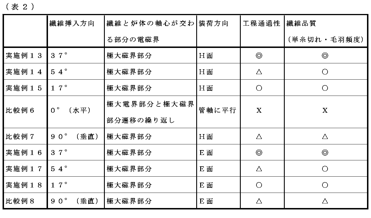
以下の実施例において、炭素繊維前駆体繊維とは、炭素含有率60質量%のPAN系耐炎化繊維をいい、中間炭素繊維とは、特に記載がない場合は炭素含有率66質量%のPAN系中間炭素繊維をいう。また、「工程通過性」の評価は、単糸が切れずに連続して炭素化(連続運転)が可能である場合を◎とし、一部の単糸が切れるが連続運転が可能である場合を○とし、単糸が切れることで切れた単糸がロールなどの搬送装置に絡みついて連続運転に支障をきたしやすい場合を△とし、繊維束全体の切断が起こり、炉体から取り出せない場合を×とした。「繊維品質」の評価は、炭素化中に繊維が全く切断しなかった場合を◎とし、炭素化中に繊維に極僅かな毛羽が発生している場合を○とし、多量の毛羽が発生している場合を△とし、繊維が完全に切断された場合を×とした。In the following examples, the carbon fiber precursor fiber refers to a PAN-based flame-retardant fiber with a carbon content of 60% by mass, and the intermediate carbon fiber refers to a PAN-based intermediate carbon fiber with a carbon content of 66% by mass unless otherwise specified. In addition, the evaluation of "process passability" was rated as ◎ when the single yarn was not broken and continuous carbonization (continuous operation) was possible, as ○ when some single yarns were broken but continuous operation was possible, as △ when the single yarn was broken and the broken single yarn became entangled in a conveying device such as a roll, which was likely to interfere with continuous operation, and as × when the entire fiber bundle was broken and could not be removed from the furnace body. The evaluation of "fiber quality" was rated as ◎ when the fiber was not broken at all during carbonization, as ○ when very little fluff was generated on the fiber during carbonization, as △ when a large amount of fluff was generated, and as × when the fiber was completely cut.
(実施例1)
図1に記載のマイクロ波加熱ユニット(マイクロ波発振器周波数:2.45GHz)を構成した。炉体としては、管軸と直交する断面の開口部が110×55mm、長さが500mmの方形導波管を用いて、図3の構成とした。繊維の導入口及び導出口は、炉体のH面(短軸管壁)に設けた。炉体の軸心と繊維走行方向との角度θは37°とした。この時、炉体内に収容される繊維の長さ(即ち、繊維の導入口中央と導出口中央とを繋ぐ線分の長さである。以下、同じ)は183mmであった。保温管としては、内径15mm、外径17mm、長さ300mmの円筒形状のシリカアルミナ管(マイクロ波の透過率=99.9%)を用いた。窒素ガス雰囲気下の炉体内にマイクロ波を導入してTEモードの電磁界分布を形成させた。マイクロ波発振器の出力は300Wとした。この炉体内の極大電界部分と誘電体である炭素繊維前駆体とが炉体の軸心で交わるように炭素繊維前駆体を0.3m/min.で走行させながら炭素化して炭素繊維を得た。得られた炭素繊維の炭素含有率は93質量%であり、繊維の切断は見られず、工程通過性は極めて良好であった。評価結果を表1に示した。
Example 1
The microwave heating unit (microwave oscillator frequency: 2.45 GHz) shown in FIG. 1 was constructed. As the furnace body, a rectangular waveguide with an opening of 110×55 mm in a cross section perpendicular to the tube axis and a length of 500 mm was used, and the configuration shown in FIG. 3 was used. The inlet and outlet of the fiber were provided on the H-plane (short axis tube wall) of the furnace body. The angle θ between the axis of the furnace body and the fiber running direction was 37°. At this time, the length of the fiber contained in the furnace body (i.e., the length of the line connecting the center of the inlet and the center of the outlet of the fiber. The same applies below) was 183 mm. As the heat retention tube, a cylindrical silica alumina tube (microwave transmittance = 99.9%) with an inner diameter of 15 mm, an outer diameter of 17 mm, and a length of 300 mm was used. Microwaves were introduced into the furnace body under a nitrogen gas atmosphere to form an electromagnetic field distribution in TE mode. The output of the microwave oscillator was 300 W. The carbon fiber precursor was carbonized while traveling at 0.3 m/min. so that the maximum electric field portion in the furnace and the carbon fiber precursor, which is a dielectric, intersected at the axis of the furnace, to obtain carbon fiber. The carbon content of the obtained carbon fiber was 93 mass%, and no fiber breakage was observed, and the processability was extremely good. The evaluation results are shown in Table 1.
(実施例2)
炉体の軸心と繊維走行方向との角度を54°に変更した他は実施例1と同様に加熱して中間炭素繊維を得た。この時、炉体内に収容される繊維の長さは136mmであった。工程中、一部の単糸に切断が見られたが、工程通過性は良好であった。評価結果を表1に示した。
Example 2
The intermediate carbon fiber was obtained by heating in the same manner as in Example 1, except that the angle between the axis of the furnace body and the fiber running direction was changed to 54°. At this time, the length of the fiber accommodated in the furnace body was 136 mm. Although some of the single yarns were broken during the process, the processability was good. The evaluation results are shown in Table 1.
(実施例3)
炉体の軸心と繊維走行方向との角度を17°とし、保温管の長さを500mmに変更した他は実施例1と同様に加熱して中間炭素繊維を得た。この時、炉体内に収容される繊維の長さは376mmであった。炉の温度は上昇したが、工程中、繊維の炭素化反応に十分な温度には至らず、中間炭素繊維及び炭素繊維を得ることができなかった。評価結果を表1に示した。
Example 3
Intermediate carbon fibers were obtained by heating in the same manner as in Example 1, except that the angle between the axis of the furnace body and the fiber running direction was set to 17° and the length of the heat-retaining tube was changed to 500 mm. At this time, the length of the fiber contained in the furnace body was 376 mm. Although the temperature of the furnace rose, it did not reach a temperature sufficient for the carbonization reaction of the fiber during the process, and intermediate carbon fibers and carbon fibers could not be obtained. The evaluation results are shown in Table 1.
(比較例1)
図1に記載のマイクロ波加熱ユニット(マイクロ波発振器周波数:2.45GHz)を構成した。炉体としては、管軸と直交する断面の開口部が110×55mm、長さが500mmの方形導波管を用いた。繊維の導入口は炉体のマイクロ波導入面に、繊維導出口は炉体の終端部に設けた。炉体の軸心と繊維走行方向との角度は0°とした。この時、炉体内に収容される繊維の長さは500mmであった。保温管としては、内径15mm、外径17mm、長さ600mmの円筒形状のシリカアルミナ管(マイクロ波の透過率=99.9%)を用いた。窒素ガス雰囲気下の炉体内にマイクロ波を導入してTEモードの電磁界分布を形成させた。マイクロ波発振器の出力は300Wとした。この炉体内を通るように、炭素繊維前駆体を0.3m/min.で走行させながら炭素化した。この時、炉体内では極大電界部分と極大磁界部分が交互に存在しているため、繊維が曝される電磁界は極大電界部分と極大磁界部分の遷移が繰り返されることになる。工程中、繊維が切断し、工程通過性は極めて不良で中間炭素繊維及び炭素繊維を得ることができなかった。評価結果を表1に示した。
(Comparative Example 1)
The microwave heating unit (microwave oscillator frequency: 2.45 GHz) shown in FIG. 1 was constructed. As the furnace body, a rectangular waveguide with an opening of 110×55 mm in a cross section perpendicular to the tube axis and a length of 500 mm was used. The fiber inlet was provided on the microwave inlet surface of the furnace body, and the fiber outlet was provided at the end of the furnace body. The angle between the axis of the furnace body and the fiber running direction was set to 0°. At this time, the length of the fiber accommodated in the furnace body was 500 mm. As the heat-retaining tube, a cylindrical silica alumina tube (microwave transmittance = 99.9%) with an inner diameter of 15 mm, an outer diameter of 17 mm, and a length of 600 mm was used. Microwaves were introduced into the furnace body under a nitrogen gas atmosphere to form an electromagnetic field distribution in TE mode. The output of the microwave oscillator was set to 300 W. Carbonization was performed while running the carbon fiber precursor through the furnace body at 0.3 m/min. At this time, since maximum electric field parts and maximum magnetic field parts alternate in the furnace, the electromagnetic field to which the fibers are exposed repeatedly transitions between maximum electric field parts and maximum magnetic field parts. During the process, the fibers were broken, and the process passability was extremely poor, so that intermediate carbon fibers and carbon fibers could not be obtained. The evaluation results are shown in Table 1.
(比較例2)
図1に記載のマイクロ波加熱ユニット(マイクロ波発振器周波数:2.45GHz)を構成した。炉体としては、管軸と直交する断面の開口部が110×55mm、長さが500mmの方形導波管を用い図8の構成とした。繊維の導入口及び導出口は、炉体のH面(短軸管壁)に設けた。炉体の軸心と繊維走行方向との角度は90°とした。この時、炉体内に収容される繊維の長さは110mmであった。保温管としては、内径15mm、外径17mm、長さ300mmの円筒形状のシリカアルミナ管(マイクロ波の透過率=99.9%)を用いた。窒素ガス雰囲気下の炉体内にマイクロ波を導入してTEモードの電磁界分布を形成させた。マイクロ波発振器の出力は300Wとした。この炉体内の極大電界部分のみを通るように、炭素繊維前駆体を0.3m/min.で走行させながら炭素化した。工程中、繊維が切断し、工程通過性は極めて不良で中間炭素繊維及び炭素繊維を得ることができなかった。評価結果を表1に示した。
(Comparative Example 2)
The microwave heating unit (microwave oscillator frequency: 2.45 GHz) shown in FIG. 1 was constructed. As the furnace body, a rectangular waveguide with an opening of 110×55 mm in a cross section perpendicular to the tube axis and a length of 500 mm was used, and the configuration shown in FIG. 8 was used. The inlet and outlet of the fiber were provided on the H surface (short axis tube wall) of the furnace body. The angle between the axis of the furnace body and the fiber running direction was 90°. At this time, the length of the fiber contained in the furnace body was 110 mm. As the heat retention tube, a cylindrical silica alumina tube (microwave transmittance = 99.9%) with an inner diameter of 15 mm, an outer diameter of 17 mm, and a length of 300 mm was used. Microwaves were introduced into the furnace body under a nitrogen gas atmosphere to form an electromagnetic field distribution in TE mode. The output of the microwave oscillator was 300 W. Carbonization was performed while running the carbon fiber precursor at 0.3 m/min. so that it passed only the maximum electric field part in this furnace body. The fibers were broken during the process, and the processability was extremely poor, so that intermediate carbon fibers and carbon fibers could not be obtained. The evaluation results are shown in Table 1.
(実施例4)
炉体内の極大磁界部分と炭素繊維前駆体とが炉体の軸心で交わるように変更した他は実施例1と同様に加熱して炭素繊維を得た。この時、炉体内に収容される繊維の長さは183mmであった。得られた炭素繊維の炭素含有率は93質量%であり、繊維の切断は見られず、工程通過性は極めて良好であった。評価結果を表1に示した。
Example 4
Carbon fibers were obtained by heating in the same manner as in Example 1, except that the maximum magnetic field portion in the furnace body and the carbon fiber precursor were changed to intersect at the axis of the furnace body. At this time, the length of the fiber contained in the furnace body was 183 mm. The carbon content of the obtained carbon fiber was 93 mass%, no fiber breakage was observed, and the process passability was extremely good. The evaluation results are shown in Table 1.
(実施例5)
炉体の軸心と繊維走行方向との角度を54°に変更した他は実施例4と同様に加熱して中間炭素繊維を得た。この時、炉体内に収容される繊維の長さは136mmであった。得られた中間炭素繊維の炭素含有率は70質量%であり、工程中、一部の単糸に切断が見られたが、工程通過性は良好であった。評価結果を表1に示した。
Example 5
The intermediate carbon fiber was obtained by heating in the same manner as in Example 4, except that the angle between the axis of the furnace body and the fiber running direction was changed to 54°. At this time, the length of the fiber accommodated in the furnace body was 136 mm. The carbon content of the obtained intermediate carbon fiber was 70 mass%, and although some of the single yarns were broken during the process, the processability was good. The evaluation results are shown in Table 1.
(実施例6)
炉体の軸心と繊維走行方向との角度を17°とし、保温管の長さを500mmに変更した他は実施例4と同様に加熱して中間炭素繊維を得た。この時、炉体内に収容される繊維の長さは376mmであった。炉の温度は上昇したが、工程中、繊維の炭素化反応に十分な温度上昇には至らず、中間炭素繊維及び炭素繊維を得ることができなかった。評価結果を表1に示した。
Example 6
Intermediate carbon fibers were obtained by heating in the same manner as in Example 4, except that the angle between the axis of the furnace body and the fiber running direction was set to 17° and the length of the heat-retaining tube was changed to 500 mm. At this time, the length of the fiber contained in the furnace body was 376 mm. Although the temperature of the furnace rose, the temperature did not rise sufficiently during the process for the carbonization reaction of the fiber, and intermediate carbon fibers and carbon fibers could not be obtained. The evaluation results are shown in Table 1.
(比較例3)
炉体内の極大磁界部分と炭素繊維前駆体とが炉体の軸心で交わるよう(即ち、図12の構成)に変更した他は比較例2と同様に加熱した。この時、炉体内に収容される繊維の長さは110mmであった。工程中、繊維の温度上昇は見られず、中間炭素繊維及び炭素繊維を得ることができなかった。評価結果を表1に示した。
(Comparative Example 3)
Heating was performed in the same manner as in Comparative Example 2, except that the maximum magnetic field portion in the furnace body and the carbon fiber precursor intersected at the axis of the furnace body (i.e., the configuration of FIG. 12). At this time, the length of the fiber contained in the furnace body was 110 mm. During the process, no temperature increase of the fiber was observed, and intermediate carbon fiber and carbon fiber could not be obtained. The evaluation results are shown in Table 1.
(実施例7)
繊維導入口及び繊維導出口を炉体のE面装荷(即ち、図4の構成)とし、炭素繊維前駆体と炉体の軸心が交わる位置を極大電界部分から極大磁界部分へと変更した他は実施例1と同様に加熱して中間炭素繊維を得た。この時、炉体内に収容される繊維の長さは91mmであった。得られた中間炭素繊維の炭素含有率は74質量%であり、繊維の切断は見られず、工程通過性は極めて良好であった。評価結果を表1に示した。
(Example 7)
The fiber inlet and fiber outlet were loaded on the E-side of the furnace body (i.e., the configuration of FIG. 4 ), and the position where the carbon fiber precursor and the axis of the furnace body intersect was changed from the maximum electric field part to the maximum magnetic field part, but heating was performed in the same manner as in Example 1 to obtain intermediate carbon fibers. At this time, the length of the fiber contained in the furnace body was 91 mm. The carbon content of the obtained intermediate carbon fiber was 74 mass%, no fiber breakage was observed, and the processability was extremely good. The evaluation results are shown in Table 1.
(実施例8)
炉体の軸心と繊維走行方向との角度を54°に変更した他は実施例7と同様に加熱して中間炭素繊維を得た。この時、炉体内に収容される繊維の長さは68mmであった。得られた中間炭素繊維の炭素含有率は72量%であり、一部の単糸に切断が見られ、加熱後の繊維は搬送ロールへ巻き付き易かった。評価結果を表1に示した。
(Example 8)
Intermediate carbon fibers were obtained by heating in the same manner as in Example 7, except that the angle between the axis of the furnace body and the fiber running direction was changed to 54°. At this time, the length of the fiber contained in the furnace body was 68 mm. The carbon content of the obtained intermediate carbon fiber was 72% by volume, some of the single yarns were broken, and the fiber after heating was easily wound around the transport roll. The evaluation results are shown in Table 1.
(実施例9)
炉体の軸心と繊維走行方向との角度を17°に変更した他は実施例7と同様に加熱して中間炭素繊維を得た。この時、炉体内に収容される繊維の長さは188mmであった。繊維の切断は見られず、工程通過性は極めて良好であった。評価結果を表1に示した。
(Example 9)
Intermediate carbon fibers were obtained by heating in the same manner as in Example 7, except that the angle between the axis of the furnace body and the fiber running direction was changed to 17°. At this time, the length of the fiber contained in the furnace body was 188 mm. No fiber breakage was observed, and the processability was extremely good. The evaluation results are shown in Table 1.
(比較例4)
図13に記載の構成とし、繊維の導入口及び導出口を、炉体のE面(長軸管壁)に設けた他は、比較例3と同様に加熱した。この時、炉体内に収容される繊維の長さは55mmであった。工程中、繊維の温度上昇は見られず、中間炭素繊維及び炭素繊維を得ることができなかった。評価結果を表1に示した。
(Comparative Example 4)
The configuration shown in Fig. 13 was used, and heating was performed in the same manner as in Comparative Example 3, except that the inlet and outlet of the fiber were provided on the E surface (long axis tube wall) of the furnace body. At this time, the length of the fiber contained in the furnace body was 55 mm. During the process, no increase in the temperature of the fiber was observed, and intermediate carbon fiber and carbon fiber could not be obtained. The evaluation results are shown in Table 1.
(実施例10)
炉体内の極大電界部分と炭素繊維前駆体が炉体の軸心で交わるように変更した他は実施例7と同様に加熱して中間炭素繊維を得た。この時、炉体内に収容される繊維の長さは91mmであった。得られた中間炭素繊維の炭素含有率は72%であり、繊維の切断は見られず、工程通過性は極めて良好であった。評価結果を表1に示した。
Example 10
An intermediate carbon fiber was obtained by heating in the same manner as in Example 7, except that the maximum electric field portion in the furnace body and the carbon fiber precursor were changed to intersect at the axis of the furnace body. At this time, the length of the fiber contained in the furnace body was 91 mm. The carbon content of the obtained intermediate carbon fiber was 72%, no fiber breakage was observed, and the processability was extremely good. The evaluation results are shown in Table 1.
(実施例11)
炉体の軸心と繊維走行方向との角度を54°に変更した他は実施例10と同様に加熱して中間炭素繊維を得た。この時、炉体内に収容される繊維の長さは68mmであった。工程中、一部の単糸に切断が見られ、加熱後の繊維において搬送ロールに巻き付き易かった。評価結果を表1に示した。
Example 11
Intermediate carbon fibers were obtained by heating in the same manner as in Example 10, except that the angle between the axis of the furnace body and the fiber running direction was changed to 54°. At this time, the length of the fiber contained in the furnace body was 68 mm. During the process, some of the single yarns were broken, and the fiber after heating was prone to winding around the transport roll. The evaluation results are shown in Table 1.
(実施例12)
炉体の軸心と繊維走行方向との角度を17°に変更した他は実施例10と同様に加熱して中間炭素繊維を得た。この時、炉体内に収容される繊維の長さは188mmであった。繊維の切断は見られず、工程通過性は極めて良好であった。評価結果を表1に示した。
Example 12
Intermediate carbon fibers were obtained by heating in the same manner as in Example 10, except that the angle between the axis of the furnace body and the fiber running direction was changed to 17°. At this time, the length of the fiber contained in the furnace body was 188 mm. No fiber breakage was observed, and the processability was extremely good. The evaluation results are shown in Table 1.
(比較例5)
炉体内の極大電界部分と炭素繊維前駆体が炉体の軸心で交わるよう(即ち、図9の構成)に変更した他は比較例4と同様に加熱した。この時、炉体内に収容される繊維の長さは55mmであった。工程中、繊維に毛羽が多量に発生し、工程通過性は極めて不良で中間炭素繊維及び炭素繊維を得ることができなかった。評価結果を表1に示した。
(Comparative Example 5)
Heating was performed in the same manner as in Comparative Example 4, except that the maximum electric field portion in the furnace body and the carbon fiber precursor were changed to intersect at the axis of the furnace body (i.e., the configuration of FIG. 9). At this time, the length of the fiber contained in the furnace body was 55 mm. During the process, a large amount of fluff was generated in the fiber, the process passability was extremely poor, and intermediate carbon fiber and carbon fiber could not be obtained. The evaluation results are shown in Table 1.

(実施例13)
加熱する繊維を炭素繊維前駆体から半導体乃至導電体である中間炭素繊維に変更した他は実施例4と同様に炭素化して炭素繊維を得た。得られた炭素繊維の炭素含有率は95質量%であり、繊維の切断は見られず、工程通過性は極めて良好であった。評価結果を表2に示した。
Example 13
Carbon fibers were obtained by carbonization in the same manner as in Example 4, except that the fiber to be heated was changed from the carbon fiber precursor to an intermediate carbon fiber which is a semiconductor or conductor. The carbon content of the obtained carbon fiber was 95 mass%, no fiber breakage was observed, and the processability was extremely good. The evaluation results are shown in Table 2.
(実施例14)
炉体の軸心と繊維走行方向との角度を54°に変更した他は実施例13と同様に加熱して炭素繊維を得た。炉体内に収容される繊維の長さは136mmであった。一部の単糸に切断が見られ、加熱後の繊維において搬送ロールに巻き付き易かった。評価結果を表2に示した。
(Example 14)
Carbon fibers were obtained by heating in the same manner as in Example 13, except that the angle between the axis of the furnace body and the fiber running direction was changed to 54°. The length of the fiber contained in the furnace body was 136 mm. Some of the single yarns were broken, and the heated fiber was easily wound around the transport roll. The evaluation results are shown in Table 2.
(実施例15)
炉体の軸心と繊維走行方向との角度を17°に変更した他は実施例13と同様に加熱して炭素繊維を得た。炉体内に収容される繊維の長さは376mmであった。工程中、一部の単糸に切断が見られたが、工程通過性は良好であった。評価結果を表2に示した。
(Example 15)
Carbon fibers were obtained by heating in the same manner as in Example 13, except that the angle between the axis of the furnace body and the fiber running direction was changed to 17°. The length of the fiber accommodated in the furnace body was 376 mm. Although some of the single yarns were broken during the process, the processability was good. The evaluation results are shown in Table 2.
(比較例6)
加熱する繊維を炭素繊維前駆体から半導体乃至導電体である中間炭素繊維に変更した他は比較例1と同様に炭素化した。工程中、繊維が切断し、工程通過性は極めて不良で炭素繊維を得ることができなかった。評価結果を表2に示した。
(Comparative Example 6)
Carbonization was carried out in the same manner as in Comparative Example 1, except that the fiber to be heated was changed from the carbon fiber precursor to an intermediate carbon fiber which is a semiconductor or conductor. During the process, the fiber was broken, the processability was extremely poor, and carbon fiber could not be obtained. The evaluation results are shown in Table 2.
(比較例7)
加熱する繊維を炭素繊維前駆体から半導体乃至導電体である中間炭素繊維に変更した他は比較例3と同様に炭素化した。工程中、単糸に切断が見られ、多量の毛羽が発生していた。評価結果を表2に示した。
(Comparative Example 7)
Carbonization was carried out in the same manner as in Comparative Example 3, except that the fiber to be heated was changed from the carbon fiber precursor to an intermediate carbon fiber which is a semiconductor or conductor. During the process, breakage of the single yarn was observed, and a large amount of fluff was generated. The evaluation results are shown in Table 2.
(実施例16)
加熱する繊維を炭素繊維前駆体から半導体乃至導電体である中間炭素繊維に変更した他は実施例7と同様に炭素化して炭素繊維を得た。得られた炭素繊維の炭素含有率は90量%であり、繊維の切断は見られず、工程通過性は極めて良好であった。評価結果を表2に示した。
(Example 16)
Carbon fibers were obtained by carbonization in the same manner as in Example 7, except that the fiber to be heated was changed from the carbon fiber precursor to an intermediate carbon fiber which is a semiconductor or conductor. The carbon content of the obtained carbon fiber was 90% by mass, no fiber breakage was observed, and the processability was extremely good. The evaluation results are shown in Table 2.
(実施例17)
加熱する繊維を炭素繊維前駆体から半導体乃至導電体である中間炭素繊維に変更した他は実施例8と同様に加熱して炭素繊維を得た。工程中、一部の単糸に切断が見られ、加熱後の繊維において搬送ロールに巻き付き易かった。評価結果を表2に示した。
(Example 17)
Carbon fibers were obtained by heating in the same manner as in Example 8, except that the fiber to be heated was changed from the carbon fiber precursor to an intermediate carbon fiber which is a semiconductor or a conductor. During the process, some of the single yarns were broken, and the heated fiber was easily wound around the transport roll. The evaluation results are shown in Table 2.
(実施例18)
加熱する繊維を炭素繊維前駆体から半導体乃至導電体である中間炭素繊維に変更した他は実施例9と同様に加熱して炭素繊維を得た。工程中、一部の単糸に切断が見られたが、工程通過性は良好であった。評価結果を表2に示した。
(Example 18)
Carbon fibers were obtained by heating in the same manner as in Example 9, except that the fibers to be heated were changed from the carbon fiber precursor to intermediate carbon fibers which are semiconductors or conductors. Although some of the single fibers were broken during the process, the processability was good. The evaluation results are shown in Table 2.
(比較例8)
加熱する繊維を炭素繊維前駆体から半導体乃至導電体である中間炭素繊維に変更した他は比較例4と同様に炭素化した。工程中、繊維に毛羽が多量に発生し、搬送用ロールへの巻き付きが起こり易かった。得られた炭素繊維の炭素含有率は90%であった。評価結果を表2に示した。
(Comparative Example 8)
Carbonization was carried out in the same manner as in Comparative Example 4, except that the fiber to be heated was changed from the carbon fiber precursor to an intermediate carbon fiber which is a semiconductor or conductor. During the process, a large amount of fuzz was generated in the fiber, and the fiber was prone to winding around the transport roll. The carbon content of the obtained carbon fiber was 90%. The evaluation results are shown in Table 2.
11・・・マイクロ波発振器
12、14・・・接続導波管
13・・・サーキュレータ
15・・・整合器
16・・・アイリス
17、109、209、309・・・短絡板
19・・・ダミーロード
100、101、201、301、401、501・・・炉体
201a、201b・・・炉体のH面
301a、301b・・・炉体のE面
103、203、303・・・繊維導入口
105、205、305・・・繊維導出口
107、207、307・・・保温管
111、113、211、213、311、313・・・金属スリーブ
150、250、350、450、550、251、351、451、551・・・被加熱連続繊維
1000、1000a、1000b、1000c、1001、1002、1003、1004・・・マイクロ波加熱ユニット
11:
Claims (7)
前記導波管内にマイクロ波を導入するマイクロ波発振器と、
を含んで成るマイクロ波加熱ユニットであって、
炭素繊維前駆体である被加熱連続繊維が前記導波管の管軸に対して角度θ°の傾斜を有してその内部を走行するように構成されており、前記角度θ°が0<θ<90であり、
前記繊維導出口が前記導波管の終端部以外の部分に形成されていることを特徴とするマイクロ波加熱ユニット。 a furnace body having a waveguide having a fiber inlet and a fiber outlet formed in a wall of the waveguide;
a microwave oscillator for introducing microwaves into the waveguide;
A microwave heating unit comprising:
The heated continuous fiber, which is a carbon fiber precursor, is configured to run inside the waveguide at an angle θ° with respect to the axis of the waveguide, the angle θ° being 0<θ<90;
13. A microwave heating unit, comprising: a waveguide having a fiber outlet formed at a portion other than a terminal end of the waveguide;
炭素含有率が66質量%未満の被加熱連続繊維を加熱して中間炭素繊維乃至炭素繊維を得る工程を含むことを特徴とする中間炭素繊維乃至炭素繊維の製造方法。 A method for producing intermediate carbon fibers or carbon fibers, comprising the steps of: heating a continuous fiber to be heated while it is running using the microwave heating unit according to any one of claims 1 to 5;
A method for producing intermediate carbon fibers or carbon fibers, comprising the step of heating heated continuous fibers having a carbon content of less than 66 mass% to obtain intermediate carbon fibers or carbon fibers.
A method for producing carbon fibers as described in claim 6, further comprising using a microwave heating unit as described in any one of claims 1 to 5 to heat a continuous fiber to be heated while it is running by a maximum magnetic field portion in a waveguide.
Applications Claiming Priority (3)
| Application Number | Priority Date | Filing Date | Title |
|---|---|---|---|
| JP2021015373 | 2021-02-02 | ||
| JP2021015373 | 2021-02-02 | ||
| PCT/JP2022/003831 WO2022168830A1 (en) | 2021-02-02 | 2022-02-01 | Microwave heating unit, and carbon fiber manufacturing method using same |
Publications (2)
| Publication Number | Publication Date |
|---|---|
| JPWO2022168830A1 JPWO2022168830A1 (en) | 2022-08-11 |
| JP7621620B2 true JP7621620B2 (en) | 2025-01-27 |
Family
ID=82741468
Family Applications (1)
| Application Number | Title | Priority Date | Filing Date |
|---|---|---|---|
| JP2022579550A Active JP7621620B2 (en) | 2021-02-02 | 2022-02-01 | Microwave heating unit and carbon fiber manufacturing method using the same |
Country Status (7)
| Country | Link |
|---|---|
| US (1) | US20240117531A1 (en) |
| EP (1) | EP4289999A4 (en) |
| JP (1) | JP7621620B2 (en) |
| KR (1) | KR20230142558A (en) |
| CN (1) | CN117280868A (en) |
| TW (1) | TWI900731B (en) |
| WO (1) | WO2022168830A1 (en) |
Citations (7)
| Publication number | Priority date | Publication date | Assignee | Title |
|---|---|---|---|---|
| JP2002538580A (en) | 1999-02-26 | 2002-11-12 | ソシエテ デ プロデユイ ネツスル ソシエテ アノニム | On-demand source or beverage heating system and method |
| DE10244941A1 (en) | 2001-09-26 | 2003-05-28 | Pueschner Gmbh & Co Kg | Microwave applicator with cavity resonator for thermal treatment of materials has wave field coupling unit with metal coupling rod extending into resonator interior |
| JP2009533562A (en) | 2006-04-15 | 2009-09-17 | 東邦テナックス株式会社 | Continuous production method of carbon fiber |
| WO2015152019A1 (en) | 2014-03-31 | 2015-10-08 | 国立大学法人 東京大学 | Carbon fiber manufacturing device and carbon fiber manufacturing method |
| WO2019170299A1 (en) | 2018-03-08 | 2019-09-12 | Siempelkamp Maschinen- Und Anlagenbau Gmbh | Continuous furnace and system for producing wooden composite boards |
| CN110257959A (en) | 2019-06-28 | 2019-09-20 | 中国科学院合肥物质科学研究院 | It is a kind of to be graphitized equipment with the carbon fiber microwave of Continuous maching |
| JP2020513486A (en) | 2016-12-19 | 2020-05-14 | エルジー・ケム・リミテッド | Carbon fiber manufacturing equipment using microwave |
Family Cites Families (6)
| Publication number | Priority date | Publication date | Assignee | Title |
|---|---|---|---|---|
| FR2458610A1 (en) * | 1979-06-07 | 1981-01-02 | Anvar | Thermal yarn processing unit |
| JPS6063045U (en) | 1983-10-07 | 1985-05-02 | ダイハツ工業株式会社 | Pedal operation amount adjustment device |
| FR2584258B1 (en) * | 1985-06-28 | 1995-04-14 | Elf Aquitaine | METHOD AND DEVICE FOR THE HEAT TREATMENT OF A CONDUCTIVE ELEMENT AT LEAST PARTIALLY CONSISTING OF A CONDUCTIVE MATERIAL |
| JP2898646B2 (en) * | 1989-02-23 | 1999-06-02 | 株式会社山海 | Microwave heating method and apparatus |
| JP6121333B2 (en) * | 2011-10-21 | 2017-04-26 | 昭和電工株式会社 | Microwave heating apparatus and microwave heating method |
| HUE041716T2 (en) | 2013-07-26 | 2019-05-28 | Teijin Ltd | Carbonization method and carbon fiber production method |
-
2022
- 2022-02-01 EP EP22749702.1A patent/EP4289999A4/en active Pending
- 2022-02-01 CN CN202280012209.2A patent/CN117280868A/en active Pending
- 2022-02-01 US US18/275,326 patent/US20240117531A1/en active Pending
- 2022-02-01 JP JP2022579550A patent/JP7621620B2/en active Active
- 2022-02-01 KR KR1020237029773A patent/KR20230142558A/en active Pending
- 2022-02-01 WO PCT/JP2022/003831 patent/WO2022168830A1/en not_active Ceased
- 2022-02-07 TW TW111104333A patent/TWI900731B/en active
Patent Citations (7)
| Publication number | Priority date | Publication date | Assignee | Title |
|---|---|---|---|---|
| JP2002538580A (en) | 1999-02-26 | 2002-11-12 | ソシエテ デ プロデユイ ネツスル ソシエテ アノニム | On-demand source or beverage heating system and method |
| DE10244941A1 (en) | 2001-09-26 | 2003-05-28 | Pueschner Gmbh & Co Kg | Microwave applicator with cavity resonator for thermal treatment of materials has wave field coupling unit with metal coupling rod extending into resonator interior |
| JP2009533562A (en) | 2006-04-15 | 2009-09-17 | 東邦テナックス株式会社 | Continuous production method of carbon fiber |
| WO2015152019A1 (en) | 2014-03-31 | 2015-10-08 | 国立大学法人 東京大学 | Carbon fiber manufacturing device and carbon fiber manufacturing method |
| JP2020513486A (en) | 2016-12-19 | 2020-05-14 | エルジー・ケム・リミテッド | Carbon fiber manufacturing equipment using microwave |
| WO2019170299A1 (en) | 2018-03-08 | 2019-09-12 | Siempelkamp Maschinen- Und Anlagenbau Gmbh | Continuous furnace and system for producing wooden composite boards |
| CN110257959A (en) | 2019-06-28 | 2019-09-20 | 中国科学院合肥物质科学研究院 | It is a kind of to be graphitized equipment with the carbon fiber microwave of Continuous maching |
Also Published As
| Publication number | Publication date |
|---|---|
| KR20230142558A (en) | 2023-10-11 |
| US20240117531A1 (en) | 2024-04-11 |
| CN117280868A (en) | 2023-12-22 |
| WO2022168830A1 (en) | 2022-08-11 |
| TW202246601A (en) | 2022-12-01 |
| EP4289999A4 (en) | 2025-10-15 |
| JPWO2022168830A1 (en) | 2022-08-11 |
| EP4289999A1 (en) | 2023-12-13 |
| TWI900731B (en) | 2025-10-11 |
Similar Documents
| Publication | Publication Date | Title |
|---|---|---|
| CN106460243B (en) | Carbon fiber manufacturing device and carbon fiber production method | |
| TWM564599U (en) | Fiber pre-oxidation equipment | |
| JP5877448B2 (en) | Heating device using microwaves | |
| TWI679321B (en) | Carbon fiber and carbon fiber manufacturing method | |
| JP2009533562A (en) | Continuous production method of carbon fiber | |
| KR20170088918A (en) | Manufacturing apparatus and preparation method of silicone oxide compounds | |
| JP7621620B2 (en) | Microwave heating unit and carbon fiber manufacturing method using the same | |
| CN214782310U (en) | A carbon fiber microwave plasma heat treatment equipment | |
| KR20200068527A (en) | Oxidation fiber manufacturing method | |
| US3607063A (en) | Manufacture of carbon filaments of high strength and modulus | |
| US11713280B2 (en) | Method for thermal treatment of a ceramic part by microwaves | |
| EP3518621A1 (en) | Fiber pre-oxidization device | |
| US20240076808A1 (en) | Apparatus and Method for Close Proximity Carbonization of Polymeric Materials for Carbon Fiber Production | |
| CN101820985B (en) | Carbon hollow fiber and manufacturing method thereof | |
| EP3517659B1 (en) | Oxidation fiber structure | |
| JPWO2008117625A1 (en) | Method for drying honeycomb formed body | |
| JP2018174081A (en) | Heating method, carbon fiber manufacturing method, carbonization apparatus and carbon fiber manufacturing apparatus | |
| US20240247412A1 (en) | Apparatus and Method for Microwave Carbonization of Polymeric Materials for Carbon Fiber Production | |
| JPS63266798A (en) | Wire drawing furnace | |
| JP2025536483A (en) | Manufacturing method for medium-high modulus large tow carbon fiber | |
| KR20120037043A (en) | Apparatus for maunfacturing carbon fiber using plasma source |
Legal Events
| Date | Code | Title | Description |
|---|---|---|---|
| A621 | Written request for application examination |
Free format text: JAPANESE INTERMEDIATE CODE: A621 Effective date: 20230725 |
|
| A521 | Request for written amendment filed |
Free format text: JAPANESE INTERMEDIATE CODE: A523 Effective date: 20230802 |
|
| AA64 | Notification of invalidation of claim of internal priority (with term) |
Free format text: JAPANESE INTERMEDIATE CODE: A241764 Effective date: 20231017 |
|
| A521 | Request for written amendment filed |
Free format text: JAPANESE INTERMEDIATE CODE: A523 Effective date: 20231117 |
|
| A131 | Notification of reasons for refusal |
Free format text: JAPANESE INTERMEDIATE CODE: A131 Effective date: 20240903 |
|
| A521 | Request for written amendment filed |
Free format text: JAPANESE INTERMEDIATE CODE: A523 Effective date: 20241030 |
|
| TRDD | Decision of grant or rejection written | ||
| A01 | Written decision to grant a patent or to grant a registration (utility model) |
Free format text: JAPANESE INTERMEDIATE CODE: A01 Effective date: 20241210 |
|
| A61 | First payment of annual fees (during grant procedure) |
Free format text: JAPANESE INTERMEDIATE CODE: A61 Effective date: 20250106 |
|
| R150 | Certificate of patent or registration of utility model |
Ref document number: 7621620 Country of ref document: JP Free format text: JAPANESE INTERMEDIATE CODE: R150 |