JP7621617B2 - Film forming apparatus and semiconductor device manufacturing method - Google Patents
Film forming apparatus and semiconductor device manufacturing method Download PDFInfo
- Publication number
- JP7621617B2 JP7621617B2 JP2021132611A JP2021132611A JP7621617B2 JP 7621617 B2 JP7621617 B2 JP 7621617B2 JP 2021132611 A JP2021132611 A JP 2021132611A JP 2021132611 A JP2021132611 A JP 2021132611A JP 7621617 B2 JP7621617 B2 JP 7621617B2
- Authority
- JP
- Japan
- Prior art keywords
- superheated steam
- mist
- substrate
- film
- solution
- Prior art date
- Legal status (The legal status is an assumption and is not a legal conclusion. Google has not performed a legal analysis and makes no representation as to the accuracy of the status listed.)
- Active
Links
Images

Classifications
-
- C—CHEMISTRY; METALLURGY
- C23—COATING METALLIC MATERIAL; COATING MATERIAL WITH METALLIC MATERIAL; CHEMICAL SURFACE TREATMENT; DIFFUSION TREATMENT OF METALLIC MATERIAL; COATING BY VACUUM EVAPORATION, BY SPUTTERING, BY ION IMPLANTATION OR BY CHEMICAL VAPOUR DEPOSITION, IN GENERAL; INHIBITING CORROSION OF METALLIC MATERIAL OR INCRUSTATION IN GENERAL
- C23C—COATING METALLIC MATERIAL; COATING MATERIAL WITH METALLIC MATERIAL; SURFACE TREATMENT OF METALLIC MATERIAL BY DIFFUSION INTO THE SURFACE, BY CHEMICAL CONVERSION OR SUBSTITUTION; COATING BY VACUUM EVAPORATION, BY SPUTTERING, BY ION IMPLANTATION OR BY CHEMICAL VAPOUR DEPOSITION, IN GENERAL
- C23C16/00—Chemical coating by decomposition of gaseous compounds, without leaving reaction products of surface material in the coating, i.e. chemical vapour deposition [CVD] processes
- C23C16/22—Chemical coating by decomposition of gaseous compounds, without leaving reaction products of surface material in the coating, i.e. chemical vapour deposition [CVD] processes characterised by the deposition of inorganic material, other than metallic material
- C23C16/30—Deposition of compounds, mixtures or solid solutions, e.g. borides, carbides, nitrides
- C23C16/40—Oxides
-
- C—CHEMISTRY; METALLURGY
- C23—COATING METALLIC MATERIAL; COATING MATERIAL WITH METALLIC MATERIAL; CHEMICAL SURFACE TREATMENT; DIFFUSION TREATMENT OF METALLIC MATERIAL; COATING BY VACUUM EVAPORATION, BY SPUTTERING, BY ION IMPLANTATION OR BY CHEMICAL VAPOUR DEPOSITION, IN GENERAL; INHIBITING CORROSION OF METALLIC MATERIAL OR INCRUSTATION IN GENERAL
- C23C—COATING METALLIC MATERIAL; COATING MATERIAL WITH METALLIC MATERIAL; SURFACE TREATMENT OF METALLIC MATERIAL BY DIFFUSION INTO THE SURFACE, BY CHEMICAL CONVERSION OR SUBSTITUTION; COATING BY VACUUM EVAPORATION, BY SPUTTERING, BY ION IMPLANTATION OR BY CHEMICAL VAPOUR DEPOSITION, IN GENERAL
- C23C16/00—Chemical coating by decomposition of gaseous compounds, without leaving reaction products of surface material in the coating, i.e. chemical vapour deposition [CVD] processes
- C23C16/44—Chemical coating by decomposition of gaseous compounds, without leaving reaction products of surface material in the coating, i.e. chemical vapour deposition [CVD] processes characterised by the method of coating
- C23C16/448—Chemical coating by decomposition of gaseous compounds, without leaving reaction products of surface material in the coating, i.e. chemical vapour deposition [CVD] processes characterised by the method of coating characterised by the method used for generating reactive gas streams, e.g. by evaporation or sublimation of precursor materials
- C23C16/4486—Chemical coating by decomposition of gaseous compounds, without leaving reaction products of surface material in the coating, i.e. chemical vapour deposition [CVD] processes characterised by the method of coating characterised by the method used for generating reactive gas streams, e.g. by evaporation or sublimation of precursor materials by producing an aerosol and subsequent evaporation of the droplets or particles
-
- C—CHEMISTRY; METALLURGY
- C23—COATING METALLIC MATERIAL; COATING MATERIAL WITH METALLIC MATERIAL; CHEMICAL SURFACE TREATMENT; DIFFUSION TREATMENT OF METALLIC MATERIAL; COATING BY VACUUM EVAPORATION, BY SPUTTERING, BY ION IMPLANTATION OR BY CHEMICAL VAPOUR DEPOSITION, IN GENERAL; INHIBITING CORROSION OF METALLIC MATERIAL OR INCRUSTATION IN GENERAL
- C23C—COATING METALLIC MATERIAL; COATING MATERIAL WITH METALLIC MATERIAL; SURFACE TREATMENT OF METALLIC MATERIAL BY DIFFUSION INTO THE SURFACE, BY CHEMICAL CONVERSION OR SUBSTITUTION; COATING BY VACUUM EVAPORATION, BY SPUTTERING, BY ION IMPLANTATION OR BY CHEMICAL VAPOUR DEPOSITION, IN GENERAL
- C23C16/00—Chemical coating by decomposition of gaseous compounds, without leaving reaction products of surface material in the coating, i.e. chemical vapour deposition [CVD] processes
- C23C16/44—Chemical coating by decomposition of gaseous compounds, without leaving reaction products of surface material in the coating, i.e. chemical vapour deposition [CVD] processes characterised by the method of coating
- C23C16/455—Chemical coating by decomposition of gaseous compounds, without leaving reaction products of surface material in the coating, i.e. chemical vapour deposition [CVD] processes characterised by the method of coating characterised by the method used for introducing gases into reaction chamber or for modifying gas flows in reaction chamber
- C23C16/45561—Gas plumbing upstream of the reaction chamber
-
- C—CHEMISTRY; METALLURGY
- C23—COATING METALLIC MATERIAL; COATING MATERIAL WITH METALLIC MATERIAL; CHEMICAL SURFACE TREATMENT; DIFFUSION TREATMENT OF METALLIC MATERIAL; COATING BY VACUUM EVAPORATION, BY SPUTTERING, BY ION IMPLANTATION OR BY CHEMICAL VAPOUR DEPOSITION, IN GENERAL; INHIBITING CORROSION OF METALLIC MATERIAL OR INCRUSTATION IN GENERAL
- C23C—COATING METALLIC MATERIAL; COATING MATERIAL WITH METALLIC MATERIAL; SURFACE TREATMENT OF METALLIC MATERIAL BY DIFFUSION INTO THE SURFACE, BY CHEMICAL CONVERSION OR SUBSTITUTION; COATING BY VACUUM EVAPORATION, BY SPUTTERING, BY ION IMPLANTATION OR BY CHEMICAL VAPOUR DEPOSITION, IN GENERAL
- C23C16/00—Chemical coating by decomposition of gaseous compounds, without leaving reaction products of surface material in the coating, i.e. chemical vapour deposition [CVD] processes
- C23C16/44—Chemical coating by decomposition of gaseous compounds, without leaving reaction products of surface material in the coating, i.e. chemical vapour deposition [CVD] processes characterised by the method of coating
- C23C16/46—Chemical coating by decomposition of gaseous compounds, without leaving reaction products of surface material in the coating, i.e. chemical vapour deposition [CVD] processes characterised by the method of coating characterised by the method used for heating the substrate
-
- C—CHEMISTRY; METALLURGY
- C30—CRYSTAL GROWTH
- C30B—SINGLE-CRYSTAL GROWTH; UNIDIRECTIONAL SOLIDIFICATION OF EUTECTIC MATERIAL OR UNIDIRECTIONAL DEMIXING OF EUTECTOID MATERIAL; REFINING BY ZONE-MELTING OF MATERIAL; PRODUCTION OF A HOMOGENEOUS POLYCRYSTALLINE MATERIAL WITH DEFINED STRUCTURE; SINGLE CRYSTALS OR HOMOGENEOUS POLYCRYSTALLINE MATERIAL WITH DEFINED STRUCTURE; AFTER-TREATMENT OF SINGLE CRYSTALS OR A HOMOGENEOUS POLYCRYSTALLINE MATERIAL WITH DEFINED STRUCTURE; APPARATUS THEREFOR
- C30B25/00—Single-crystal growth by chemical reaction of reactive gases, e.g. chemical vapour-deposition growth
- C30B25/02—Epitaxial-layer growth
- C30B25/10—Heating of the reaction chamber or the substrate
-
- C—CHEMISTRY; METALLURGY
- C30—CRYSTAL GROWTH
- C30B—SINGLE-CRYSTAL GROWTH; UNIDIRECTIONAL SOLIDIFICATION OF EUTECTIC MATERIAL OR UNIDIRECTIONAL DEMIXING OF EUTECTOID MATERIAL; REFINING BY ZONE-MELTING OF MATERIAL; PRODUCTION OF A HOMOGENEOUS POLYCRYSTALLINE MATERIAL WITH DEFINED STRUCTURE; SINGLE CRYSTALS OR HOMOGENEOUS POLYCRYSTALLINE MATERIAL WITH DEFINED STRUCTURE; AFTER-TREATMENT OF SINGLE CRYSTALS OR A HOMOGENEOUS POLYCRYSTALLINE MATERIAL WITH DEFINED STRUCTURE; APPARATUS THEREFOR
- C30B25/00—Single-crystal growth by chemical reaction of reactive gases, e.g. chemical vapour-deposition growth
- C30B25/02—Epitaxial-layer growth
- C30B25/14—Feed and outlet means for the gases; Modifying the flow of the reactive gases
-
- C—CHEMISTRY; METALLURGY
- C30—CRYSTAL GROWTH
- C30B—SINGLE-CRYSTAL GROWTH; UNIDIRECTIONAL SOLIDIFICATION OF EUTECTIC MATERIAL OR UNIDIRECTIONAL DEMIXING OF EUTECTOID MATERIAL; REFINING BY ZONE-MELTING OF MATERIAL; PRODUCTION OF A HOMOGENEOUS POLYCRYSTALLINE MATERIAL WITH DEFINED STRUCTURE; SINGLE CRYSTALS OR HOMOGENEOUS POLYCRYSTALLINE MATERIAL WITH DEFINED STRUCTURE; AFTER-TREATMENT OF SINGLE CRYSTALS OR A HOMOGENEOUS POLYCRYSTALLINE MATERIAL WITH DEFINED STRUCTURE; APPARATUS THEREFOR
- C30B25/00—Single-crystal growth by chemical reaction of reactive gases, e.g. chemical vapour-deposition growth
- C30B25/02—Epitaxial-layer growth
- C30B25/18—Epitaxial-layer growth characterised by the substrate
- C30B25/20—Epitaxial-layer growth characterised by the substrate the substrate being of the same materials as the epitaxial layer
-
- C—CHEMISTRY; METALLURGY
- C30—CRYSTAL GROWTH
- C30B—SINGLE-CRYSTAL GROWTH; UNIDIRECTIONAL SOLIDIFICATION OF EUTECTIC MATERIAL OR UNIDIRECTIONAL DEMIXING OF EUTECTOID MATERIAL; REFINING BY ZONE-MELTING OF MATERIAL; PRODUCTION OF A HOMOGENEOUS POLYCRYSTALLINE MATERIAL WITH DEFINED STRUCTURE; SINGLE CRYSTALS OR HOMOGENEOUS POLYCRYSTALLINE MATERIAL WITH DEFINED STRUCTURE; AFTER-TREATMENT OF SINGLE CRYSTALS OR A HOMOGENEOUS POLYCRYSTALLINE MATERIAL WITH DEFINED STRUCTURE; APPARATUS THEREFOR
- C30B29/00—Single crystals or homogeneous polycrystalline material with defined structure characterised by the material or by their shape
- C30B29/10—Inorganic compounds or compositions
- C30B29/16—Oxides
-
- C—CHEMISTRY; METALLURGY
- C30—CRYSTAL GROWTH
- C30B—SINGLE-CRYSTAL GROWTH; UNIDIRECTIONAL SOLIDIFICATION OF EUTECTIC MATERIAL OR UNIDIRECTIONAL DEMIXING OF EUTECTOID MATERIAL; REFINING BY ZONE-MELTING OF MATERIAL; PRODUCTION OF A HOMOGENEOUS POLYCRYSTALLINE MATERIAL WITH DEFINED STRUCTURE; SINGLE CRYSTALS OR HOMOGENEOUS POLYCRYSTALLINE MATERIAL WITH DEFINED STRUCTURE; AFTER-TREATMENT OF SINGLE CRYSTALS OR A HOMOGENEOUS POLYCRYSTALLINE MATERIAL WITH DEFINED STRUCTURE; APPARATUS THEREFOR
- C30B35/00—Apparatus not otherwise provided for, specially adapted for the growth, production or after-treatment of single crystals or of a homogeneous polycrystalline material with defined structure
-
- H—ELECTRICITY
- H10—SEMICONDUCTOR DEVICES; ELECTRIC SOLID-STATE DEVICES NOT OTHERWISE PROVIDED FOR
- H10P—GENERIC PROCESSES OR APPARATUS FOR THE MANUFACTURE OR TREATMENT OF DEVICES COVERED BY CLASS H10
- H10P14/00—Formation of materials, e.g. in the shape of layers or pillars
- H10P14/20—Formation of materials, e.g. in the shape of layers or pillars of semiconductor materials
- H10P14/24—Formation of materials, e.g. in the shape of layers or pillars of semiconductor materials using chemical vapour deposition [CVD]
-
- H—ELECTRICITY
- H10—SEMICONDUCTOR DEVICES; ELECTRIC SOLID-STATE DEVICES NOT OTHERWISE PROVIDED FOR
- H10P—GENERIC PROCESSES OR APPARATUS FOR THE MANUFACTURE OR TREATMENT OF DEVICES COVERED BY CLASS H10
- H10P14/00—Formation of materials, e.g. in the shape of layers or pillars
- H10P14/20—Formation of materials, e.g. in the shape of layers or pillars of semiconductor materials
- H10P14/26—Formation of materials, e.g. in the shape of layers or pillars of semiconductor materials using liquid deposition
- H10P14/265—Formation of materials, e.g. in the shape of layers or pillars of semiconductor materials using liquid deposition using solutions
-
- H—ELECTRICITY
- H10—SEMICONDUCTOR DEVICES; ELECTRIC SOLID-STATE DEVICES NOT OTHERWISE PROVIDED FOR
- H10P—GENERIC PROCESSES OR APPARATUS FOR THE MANUFACTURE OR TREATMENT OF DEVICES COVERED BY CLASS H10
- H10P14/00—Formation of materials, e.g. in the shape of layers or pillars
- H10P14/20—Formation of materials, e.g. in the shape of layers or pillars of semiconductor materials
- H10P14/29—Formation of materials, e.g. in the shape of layers or pillars of semiconductor materials characterised by the substrates
- H10P14/2901—Materials
- H10P14/2918—Materials being semiconductor metal oxides
-
- H—ELECTRICITY
- H10—SEMICONDUCTOR DEVICES; ELECTRIC SOLID-STATE DEVICES NOT OTHERWISE PROVIDED FOR
- H10P—GENERIC PROCESSES OR APPARATUS FOR THE MANUFACTURE OR TREATMENT OF DEVICES COVERED BY CLASS H10
- H10P14/00—Formation of materials, e.g. in the shape of layers or pillars
- H10P14/20—Formation of materials, e.g. in the shape of layers or pillars of semiconductor materials
- H10P14/34—Deposited materials, e.g. layers
- H10P14/3402—Deposited materials, e.g. layers characterised by the chemical composition
- H10P14/3434—Deposited materials, e.g. layers characterised by the chemical composition being oxide semiconductor materials
-
- H—ELECTRICITY
- H10—SEMICONDUCTOR DEVICES; ELECTRIC SOLID-STATE DEVICES NOT OTHERWISE PROVIDED FOR
- H10P—GENERIC PROCESSES OR APPARATUS FOR THE MANUFACTURE OR TREATMENT OF DEVICES COVERED BY CLASS H10
- H10P14/00—Formation of materials, e.g. in the shape of layers or pillars
- H10P14/20—Formation of materials, e.g. in the shape of layers or pillars of semiconductor materials
- H10P14/34—Deposited materials, e.g. layers
- H10P14/3438—Doping during depositing
- H10P14/3441—Conductivity type
- H10P14/3444—P-type
-
- H—ELECTRICITY
- H10—SEMICONDUCTOR DEVICES; ELECTRIC SOLID-STATE DEVICES NOT OTHERWISE PROVIDED FOR
- H10P—GENERIC PROCESSES OR APPARATUS FOR THE MANUFACTURE OR TREATMENT OF DEVICES COVERED BY CLASS H10
- H10P14/00—Formation of materials, e.g. in the shape of layers or pillars
- H10P14/20—Formation of materials, e.g. in the shape of layers or pillars of semiconductor materials
- H10P14/34—Deposited materials, e.g. layers
- H10P14/3451—Structure
- H10P14/3452—Microstructure
- H10P14/3458—Monocrystalline
Landscapes
- Chemical & Material Sciences (AREA)
- Metallurgy (AREA)
- Engineering & Computer Science (AREA)
- Materials Engineering (AREA)
- Organic Chemistry (AREA)
- Chemical Kinetics & Catalysis (AREA)
- General Chemical & Material Sciences (AREA)
- Crystallography & Structural Chemistry (AREA)
- Mechanical Engineering (AREA)
- Inorganic Chemistry (AREA)
- Dispersion Chemistry (AREA)
- Crystals, And After-Treatments Of Crystals (AREA)
- Chemical Vapour Deposition (AREA)
- Physical Deposition Of Substances That Are Components Of Semiconductor Devices (AREA)
Description
本明細書に開示の技術は、成膜装置と半導体装置の製造方法に関する。 The technology disclosed in this specification relates to a film forming apparatus and a method for manufacturing a semiconductor device.
特許文献1には、基板の表面に膜を成長させる成膜装置が開示されている。この成膜装置は、溶媒に膜材料が溶解した溶液のミストと加熱ガスを基板の表面に供給する。これによって、基板の表面に膜を成長させる。この構成によれば、ミストから溶媒が蒸発することを抑制しながら加熱ガスによってミストを加熱することができる。高温のミストが基板の表面に供給されるので、基板の温度低下を抑制できる。したがって、基板の表面に安定した品質の膜をエピタキシャル成長させることができる。 Patent Document 1 discloses a film formation apparatus for growing a film on the surface of a substrate. This film formation apparatus supplies a mist of a solution in which a film material is dissolved in a solvent and a heated gas to the surface of the substrate. In this way, a film is grown on the surface of the substrate. With this configuration, the mist can be heated by the heated gas while preventing the solvent from evaporating from the mist. Since high-temperature mist is supplied to the surface of the substrate, a drop in the temperature of the substrate can be prevented. Therefore, a film of stable quality can be epitaxially grown on the surface of the substrate.
特許文献1の技術では、加熱ガスによるミストの加熱効率がそれほど高くないという問題があった。本明細書では、より効率的にミストを加熱することができる技術を提案する。 The technology in Patent Document 1 had a problem in that the efficiency of heating the mist with the heating gas was not very high. This specification proposes a technology that can heat the mist more efficiently.
本明細書が開示する成膜装置は、基板を載置するステージと、前記基板を加熱するヒータと、溶媒に膜材料が溶解した溶液のミストを供給するミスト供給源と、前記溶媒と同じ材料の過熱蒸気を供給する過熱蒸気供給源と、前記ミストと前記過熱蒸気を前記基板の表面に向かって送出する送出装置、を有する。前記成膜装置は、前記基板の前記表面に前記膜材料を含む膜を成長させる。 The film formation apparatus disclosed in this specification includes a stage for placing a substrate, a heater for heating the substrate, a mist supply source for supplying a mist of a solution in which a film material is dissolved in a solvent, a superheated vapor supply source for supplying superheated vapor of the same material as the solvent, and a delivery device for delivering the mist and the superheated vapor toward the surface of the substrate. The film formation apparatus grows a film containing the film material on the surface of the substrate.
なお、過熱蒸気とは、沸点よりも高い温度を有するガスを意味する。 Note that superheated steam refers to gas that has a temperature higher than its boiling point.
この成膜装置では、ミストと過熱蒸気が基板の表面に向かって送出される。ミストと過熱蒸気が基板の表面に向かって送出されるときに、過熱蒸気によってミストが加熱される。蒸気の温度を沸点の温度よりも高くするためには潜熱分のエネルギーが必要であるため、過熱蒸気の分子エネルギーは飽和蒸気(すなわち、沸点と等しい温度を有するガス)の分子エネルギーよりもはるかに大きい。このため、過熱蒸気によれば、飽和蒸気よりも効率的にミストを加熱することができる。すなわち、過熱蒸気によれば、ミストから溶媒が蒸発することを抑制しながらミストを効率的に加熱することができる。したがって、この成膜装置によれば、基板の表面により安定した品質の膜を成長させることができる。 In this film formation apparatus, mist and superheated steam are sent toward the surface of the substrate. As the mist and superheated steam are sent toward the surface of the substrate, the mist is heated by the superheated steam. Since latent heat energy is required to raise the temperature of the steam above the boiling point, the molecular energy of the superheated steam is much greater than the molecular energy of saturated steam (i.e., a gas having a temperature equal to the boiling point). For this reason, superheated steam can heat the mist more efficiently than saturated steam. In other words, superheated steam can efficiently heat the mist while suppressing the evaporation of the solvent from the mist. Therefore, this film formation apparatus can grow a film of more stable quality on the surface of the substrate.
また、本明細書が開示する半導体装置の製造方法は、成膜装置を用いて半導体装置を製造する。前記成膜装置が、基板を載置するステージと、前記基板を加熱するヒータと、溶媒に膜材料が溶解した溶液のミストを供給するミスト供給源と、前記溶媒と同じ材料の過熱蒸気を供給する過熱蒸気供給源と、前記ミストと前記過熱蒸気を送出する送出装置、を有する。この製造方法は、前記送出装置から前記基板の表面に向かって前記ミストと前記過熱蒸気を送出することによって、前記基板の前記表面に前記膜材料を含む膜を成長させる工程を有する。 The present specification also discloses a method for manufacturing a semiconductor device, which uses a film formation apparatus to manufacture a semiconductor device. The film formation apparatus includes a stage for placing a substrate, a heater for heating the substrate, a mist supply source for supplying a mist of a solution in which a film material is dissolved in a solvent, a superheated vapor supply source for supplying superheated vapor of the same material as the solvent, and a delivery device for delivering the mist and the superheated vapor. This manufacturing method includes a step of growing a film containing the film material on the surface of the substrate by delivering the mist and the superheated vapor from the delivery device toward the surface of the substrate.
この製造方法によれば、基板の表面により安定した品質の膜を成長させることができる。 This manufacturing method allows a film of more stable quality to be grown on the surface of the substrate.
本明細書が開示する一例の成膜装置は、前記基板の前記表面に前記膜をエピタキシャル成長させてもよい。 The example film forming apparatus disclosed in this specification may epitaxially grow the film on the surface of the substrate.
本明細書が開示する一例の成膜装置では、前記溶媒が、H2Oであり、前記過熱蒸気が、過熱水蒸気であってもよい。 In the example of the film forming apparatus disclosed in the present specification, the solvent may be H 2 O, and the superheated steam may be superheated water steam.
本明細書が開示する一例の成膜装置では、前記ミストと前記過熱水蒸気の合流位置における前記過熱水蒸気の質量速度Gと、前記合流位置における前記過熱水蒸気の温度Tが、T<530G-0.15の関係を満たしてもよい。 In the film forming apparatus disclosed in the present specification, a mass velocity G of the superheated steam at a joining position of the mist and the superheated steam and a temperature T of the superheated steam at the joining position may satisfy the relationship T<530G −0.15 .
この構成によれば、過熱水蒸気によるミストの加熱効率をより高めることができる。 This configuration can further improve the heating efficiency of the mist using superheated steam.
本明細書が開示する一例の成膜装置では、前記過熱水蒸気の温度が175℃未満であってもよい。 In one example of a film forming apparatus disclosed in this specification, the temperature of the superheated steam may be less than 175°C.
本明細書が開示する一例の成膜装置では、前記過熱水蒸気の温度が150℃未満であってもよい。 In one example of a film forming apparatus disclosed in this specification, the temperature of the superheated steam may be less than 150°C.
本明細書が開示する一例の成膜装置では、前記過熱水蒸気が流れる流路内の気圧が大気圧未満であってもよい。前記過熱水蒸気の温度が100℃未満であってもよい。 In one example of a film forming apparatus disclosed in this specification, the air pressure in the flow path through which the superheated steam flows may be less than atmospheric pressure. The temperature of the superheated steam may be less than 100°C.
このように、流路内の気圧が大気圧未満の場合には、水の沸点が100℃未満となるので、過熱水蒸気の温度が100℃未満となり得る。 In this way, when the air pressure inside the flow path is less than atmospheric pressure, the boiling point of water is less than 100°C, so the temperature of the superheated steam can be less than 100°C.
本明細書が開示する一例の成膜装置では、前記送出装置が、前記ミストと前記過熱蒸気の混合体が流れる混合流路を有していてもよい。前記混合体が、前記混合流路を通って前記基板の前記表面に送出されてもよい。 In one example of a film forming apparatus disclosed in this specification, the delivery device may have a mixing passage through which a mixture of the mist and the superheated steam flows. The mixture may be delivered to the surface of the substrate through the mixing passage.
本明細書が開示する一例の成膜装置では、前記送出装置が、第1流路と、前記第1流路から分離されている第2流路を有していてもよい。前記ミストが、前記第1流路を通って前記基板の前記表面に送出されてもよい。前記過熱蒸気が、前記第2流路を通って前記基板の前記表面に送出されてもよい。 In one example of a film forming apparatus disclosed in this specification, the delivery device may have a first flow path and a second flow path separated from the first flow path. The mist may be delivered to the surface of the substrate through the first flow path. The superheated steam may be delivered to the surface of the substrate through the second flow path.
本明細書が開示する一例の成膜装置では、前記過熱蒸気供給源が、前記溶媒と同じ材料によって構成された液体材料を前記液体材料の沸点よりも低い第1温度まで加熱し、その後、前記液体材料を減圧することによって前記液体材料の前記沸点を前記第1温度よりも低い温度まで低下させることによって前記過熱蒸気を発生させてもよい。 In one example of a film forming apparatus disclosed in this specification, the superheated vapor supply source may generate the superheated vapor by heating a liquid material made of the same material as the solvent to a first temperature lower than the boiling point of the liquid material, and then reducing the pressure of the liquid material to lower the boiling point of the liquid material to a temperature lower than the first temperature.
この構成によれば、大量の過熱蒸気を短時間で発生させることができる。 This configuration allows a large amount of superheated steam to be generated in a short period of time.
図1に示す実施例1の成膜装置は、基板12の表面に膜をエピタキシャル成長させる装置である。実施例1の成膜装置は、エピタキシャル成長させた膜を有する半導体装置の製造に用いられる。実施例1の成膜装置は、成膜炉15、ミスト発生槽20、及び、過熱水蒸気発生装置80を有している。
The film formation apparatus of Example 1 shown in FIG. 1 is an apparatus for epitaxially growing a film on the surface of a
成膜炉15内に、サセプタ16が配置されている。サセプタ16は、水平に配置された平坦な上面を有している。サセプタ16上には、基板12が載置される。サセプタ16は、ヒータ14を内蔵している。ヒータ14によって、基板12が加熱される。サセプタ16は、その中心軸回りに回転することができる。サセプタ16が回転することで、サセプタ16上の基板12が面内で回転する。
A
ミスト発生槽20は、密閉型の容器である。ミスト発生槽20は、基板12の表面にエピタキシャル成長させる膜の原料を水(H2O)に溶かした溶液21を貯留している。例えば、酸化ガリウム(Ga2O3)の膜をエピタキシャル成長させる場合には、溶液21として水にガリウムが溶解した溶液を用いることができる。また、溶液21中に、酸化ガリウム膜にn型またはp型のドーパントを付与するための原料(例えば、フッ化アンモニウム等)がさらに溶解していてもよい。また、溶液21中に、塩酸が含まれていてもよい。溶液21の水面21aとミスト発生槽20の上面の間には、空間26が設けられている。ミスト発生槽20の底面には、超音波振動子28が設置されている。超音波振動子28は、ミスト発生槽20内に貯留されている溶液21に超音波を印加する。溶液21に超音波が印加されると、溶液21の水面21aが振動して、溶液21の上部の空間26に溶液21のミスト(以下、溶液ミスト72という)が発生する。ミスト発生槽20の上面には、溶液ミスト供給路24の上流端が接続されている。ミスト発生槽20の外周壁の上部には、搬送ガス供給路22の下流端が接続されている。搬送ガス供給路22の上流端は、図示しない搬送ガス供給源に接続されている。搬送ガス供給路22は、搬送ガス供給源からミスト発生槽20内の空間26に搬送ガス23を導入する。搬送ガス23は、例えば、窒素等の不活性ガスである。搬送ガス供給路22から空間26内に導入された搬送ガス23は、空間26から溶液ミスト供給路24へ流れる。このとき、空間26内の溶液ミスト72が、搬送ガス23とともに溶液ミスト供給路24へ流れる。
The mist generating tank 20 is a sealed container. The mist generating tank 20 stores a solution 21 in which the raw material of the film to be epitaxially grown on the surface of the
溶液ミスト供給路24は、成膜炉15の内部まで伸びている。溶液ミスト供給路24の下流端には、サセプタ16の上面に向かって伸びるノズル34が形成されている。溶液ミスト供給路24の下流端まで流れた溶液ミスト72は、ノズル34からサセプタ16上の基板12の上面に向かって吐出される。
The solution mist supply path 24 extends into the interior of the
過熱水蒸気発生装置80は、水貯留槽60と加熱炉40を有している。 The superheated steam generator 80 has a water storage tank 60 and a heating furnace 40.
水貯留槽60は、密閉型の容器である。水貯留槽60は、水(より詳細には、純水(H2O))61を貯留している。水61の水面61aと水貯留槽60の上面との間には、空間66が設けられている。水貯留槽60の底面には、超音波振動子68が設置されている。超音波振動子68は、水貯留槽60内に貯留されている水61に超音波を印加する。水61に超音波が印加されると、水61の水面61aが振動して、水61の上部の空間66に水61のミスト(以下、水ミスト70という)が発生する。水貯留槽60の上面には、水ミスト供給路64の上流端が接続されている。水貯留槽60の外周壁の上部には、搬送ガス供給路62の下流端が接続されている。搬送ガス供給路62の上流端は、図示しない搬送ガス供給源に接続されている。搬送ガス供給路62は、搬送ガス供給源から水貯留槽60内の空間66に搬送ガス63を導入する。搬送ガス63は、例えば、窒素等の不活性ガスである。搬送ガス供給路62から空間66内に導入された搬送ガス63は、空間66から水ミスト供給路64へ流れる。このとき、空間66内の水ミスト70が、搬送ガス63とともに水ミスト供給路64へ流れる。 The water tank 60 is a sealed container. The water tank 60 stores water (more specifically, pure water (H 2 O)) 61. A space 66 is provided between the water surface 61a of the water 61 and the upper surface of the water tank 60. An ultrasonic vibrator 68 is installed on the bottom surface of the water tank 60. The ultrasonic vibrator 68 applies ultrasonic waves to the water 61 stored in the water tank 60. When ultrasonic waves are applied to the water 61, the water surface 61a of the water 61 vibrates, and mist of the water 61 (hereinafter referred to as water mist 70) is generated in the space 66 above the water 61. The upstream end of the water mist supply path 64 is connected to the upper surface of the water tank 60. The downstream end of the carrier gas supply path 62 is connected to the upper part of the outer peripheral wall of the water tank 60. The upstream end of the carrier gas supply path 62 is connected to a carrier gas supply source not shown. The carrier gas supply path 62 introduces a carrier gas 63 from a carrier gas supply source into a space 66 in the water storage tank 60. The carrier gas 63 is, for example, an inert gas such as nitrogen. The carrier gas 63 introduced from the carrier gas supply path 62 into the space 66 flows from the space 66 to the water mist supply path 64. At this time, the water mist 70 in the space 66 flows into the water mist supply path 64 together with the carrier gas 63.
加熱炉40は、上流端40aから下流端40bまで延びる管状炉である。加熱炉40の外側に、ヒータ44が配置されている。ヒータ44は、電熱線式のヒータであって、加熱炉40の外周壁に沿って配置されている。ヒータ44は加熱炉40の外周壁を加熱し、それによって加熱炉40の内部が加熱される。加熱炉40の上流端40aには、水ミスト供給路64の下流端が接続されている。加熱炉40の下流端40bには、過熱水蒸気供給路42の上流端が接続されている。加熱炉40には、水ミスト供給路64から水ミスト70と搬送ガス63が導入される。水ミスト70と搬送ガス63は、加熱炉40内を上流端40aから下流端40bまで流れる。水ミスト70と搬送ガス63は、加熱炉40内で加熱される。水ミスト70は、加熱炉40内を流れる間に蒸発して水蒸気となる。加熱炉40内で発生した水蒸気が流れる流路(すなわち、加熱炉40、過熱水蒸気供給路42、及び、成膜炉15)の内部の気圧は、略大気圧である。加熱炉40内において、水蒸気は100℃(すなわち、大気圧下における水の沸点)よりも高温まで加熱される。したがって、加熱炉40内で過熱水蒸気43が発生する。過熱水蒸気43は、加熱炉40から過熱水蒸気供給路42へ流れる。過熱水蒸気43は、溶液21の溶媒である水(H2O)と同じ材料の過熱蒸気である。 The heating furnace 40 is a tubular furnace extending from an upstream end 40a to a downstream end 40b. A heater 44 is disposed on the outside of the heating furnace 40. The heater 44 is an electric wire heater and is disposed along the outer peripheral wall of the heating furnace 40. The heater 44 heats the outer peripheral wall of the heating furnace 40, thereby heating the inside of the heating furnace 40. The downstream end of the water mist supply passage 64 is connected to the upstream end 40a of the heating furnace 40. The upstream end of the superheated steam supply passage 42 is connected to the downstream end 40b of the heating furnace 40. Water mist 70 and carrier gas 63 are introduced into the heating furnace 40 from the water mist supply passage 64. The water mist 70 and carrier gas 63 flow from the upstream end 40a to the downstream end 40b in the heating furnace 40. The water mist 70 and carrier gas 63 are heated in the heating furnace 40. The water mist 70 evaporates while flowing in the heating furnace 40 and becomes water vapor. The pressure inside the flow paths (i.e., the heating furnace 40, the superheated steam supply path 42, and the film forming furnace 15) through which the water vapor generated in the heating furnace 40 flows is approximately atmospheric pressure. In the heating furnace 40, the water vapor is heated to a temperature higher than 100° C. (i.e., the boiling point of water under atmospheric pressure). Thus, superheated steam 43 is generated in the heating furnace 40. The superheated steam 43 flows from the heating furnace 40 to the superheated steam supply path 42. The superheated steam 43 is superheated steam of the same material as water (H 2 O), which is the solvent of the solution 21.
過熱水蒸気供給路42は、成膜炉15の内部まで伸びている。過熱水蒸気供給路42の下流端には、サセプタ16の上面に向かって伸びるノズル32が形成されている。過熱水蒸気供給路42の下流端まで流れた過熱水蒸気43は、ノズル32からサセプタ16上の基板12の上面に向かって吐出される。
The superheated steam supply passage 42 extends into the interior of the
次に、実施例1の成膜装置を用いた成膜方法について説明する。ここでは、基板12として、β型酸化ガリウム(β-Ga2O3)の単結晶によって構成された半導体基板を用いる。また、溶液21として、水に塩化ガリウム(GaCl3、Ga2Cl6)が溶解した水溶液を用いる。また、搬送ガス23、63として窒素ガスを用いる。
Next, a film forming method using the film forming apparatus of Example 1 will be described. Here, a semiconductor substrate made of a single crystal of β-type gallium oxide (β-Ga 2 O 3 ) is used as the
まず、サセプタ16上に基板12を設置する。次に、サセプタ16を回転させるとともに、ヒータ14によって、基板12を加熱する。基板12の温度が安定したら、超音波振動子68を動作させることによって、水貯留槽60の空間66内に水ミスト70を発生させる。さらに、搬送ガス供給路62から水貯留槽60に搬送ガス63を導入する。すると、水ミスト70が水ミスト供給路64を通って加熱炉40内に流入し、加熱炉40内で過熱水蒸気43が生成される。過熱水蒸気43は、過熱水蒸気供給路42を通ってノズル32へ流入する。したがって、ノズル32から基板12の上面に向かって過熱水蒸気43が吐出される。また、超音波振動子68を動作させるのと略同時に、超音波振動子28を動作させる。これによって、ミスト発生槽20の空間26内に溶液ミスト72を発生させる。さらに、搬送ガス供給路22からミスト発生槽20に搬送ガス23を導入する。すると、溶液ミスト72が溶液ミスト供給路24を通ってノズル34へ流入する。したがって、ノズル34から基板12の上面に向かって溶液ミスト72が吐出される。
First, the
ノズル32から吐出された過熱水蒸気43とノズル34から吐出された溶液ミスト72は、基板12の上部で合流する。ノズル32の吐出方向とノズル34の吐出方向の間の角度は、90°未満に設定されている。このため、合流位置における過熱水蒸気43と溶液ミスト72の相対速度Vrは、ノズル32から吐出される過熱水蒸気43の流速V43よりも低い。過熱水蒸気43と溶液ミスト72は、基板12の上部で混合される。したがって、過熱水蒸気43と溶液ミスト72の混合体が、基板12の上面に供給される。
The superheated steam 43 discharged from the nozzle 32 and the solution mist 72 discharged from the nozzle 34 join together above the
過熱水蒸気43と溶液ミスト72が混合されると、溶液ミスト72が過熱水蒸気43によって加熱される。過熱水蒸気43が高いエネルギーを有しているので、溶液ミスト72を効率的に加熱することができる。 When the superheated steam 43 and the solution mist 72 are mixed, the solution mist 72 is heated by the superheated steam 43. Since the superheated steam 43 has high energy, the solution mist 72 can be heated efficiently.
過熱水蒸気43と溶液ミスト72の混合体が基板12の上面に向かって吐出されると、溶液ミスト72が基板12の上面に付着する。基板12の温度が溶液ミスト72の温度よりも高いので、溶液ミスト72(すなわち、溶液21)が基板12上で化学反応を起こす。その結果、基板12上に、β型酸化ガリウム(β-Ga2O3)が生成される。基板12の表面に継続的に溶液ミスト72が供給されるので、基板12の上面に酸化ガリウム膜が成長する。基板12の表面に単結晶の酸化ガリウム膜がエピタキシャル成長する。このように形成された酸化ガリウム膜を用いて、半導体装置を製造することができる。溶液21がドーパントの原料を含む場合には、酸化ガリウム膜にはドーパントが取り込まれる。例えば、溶液21がフッ化アンモニウム(NH4F)を含む場合には、フッ素がドープされた酸化ガリウム膜が形成される。
When the mixture of the superheated steam 43 and the solution mist 72 is discharged toward the upper surface of the
溶液ミスト72が基板12の上面に付着するときに、基板12から熱が奪われる。これによって基板12の温度が低下すると、酸化ガリウム膜の膜質が低下する。これに対し、実施例1では、溶液ミスト72が過熱水蒸気43によって加熱されているので、溶液ミスト72が基板12の上面に付着するときに基板12から熱が奪われ難い。したがって、基板12を適切な温度に安定して維持することができる。したがって、基板12の上面に、好適に酸化ガリウム膜をエピタキシャル成長させることができる。
When the solution mist 72 adheres to the upper surface of the
また、溶液ミスト72が加熱されるときに溶液ミスト72から水(すなわち、溶媒)が蒸発すると、溶液ミスト72の各液滴を構成する溶液21の濃度が上昇する。このように、各液滴を構成する溶液21の濃度が変化すると、成長させる膜の特性の制御が困難となる。また、各液滴を構成する溶液21から水が過度に蒸発すると、溶液21が固体微粒子に変化する。このような固体微粒子が発生すると、成長させる膜に固体微粒子が付着して膜質が悪化する。しかしながら、実施例1の成膜装置では、過熱水蒸気43によって溶液ミスト72を加熱するので、溶液ミスト72の周囲で水蒸気の分圧が高く、溶液ミスト72から水が蒸発し難い。このため、適切な濃度の溶液21を溶液ミスト72として基板12の上面に供給できる。このため、基板12の上面に高品質な膜を成長させることができる。
In addition, when water (i.e., solvent) evaporates from the solution mist 72 when the solution mist 72 is heated, the concentration of the solution 21 constituting each droplet of the solution mist 72 increases. When the concentration of the solution 21 constituting each droplet changes in this way, it becomes difficult to control the characteristics of the film to be grown. In addition, when water evaporates excessively from the solution 21 constituting each droplet, the solution 21 changes into solid fine particles. When such solid fine particles are generated, the solid fine particles adhere to the film to be grown, deteriorating the film quality. However, in the film forming apparatus of Example 1, the solution mist 72 is heated by the superheated steam 43, so that the partial pressure of the water vapor is high around the solution mist 72, and water is difficult to evaporate from the solution mist 72. Therefore, the solution 21 of an appropriate concentration can be supplied to the upper surface of the
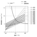
気体によって水を加熱するときの水の蒸発速度S(kg/(m2・hr))は、気体の種類、気体の質量速度G(kg/(m2・hr))、及び、気体の温度T(℃)によって異なる。なお、質量速度Gは、水に向かって気体を流すときに単位時間あたりに流れる気体の質量である。図2は、静止状態の水を気体(空気または過熱水蒸気)によって加熱するときの水の蒸発速度Sを示している。図2に示すように、空気と過熱水蒸気のそれぞれにおいて、質量速度Gが高いほど蒸発速度Sが高くなる。また、各質量速度Gにおいて、温度Tが高くなるほど蒸発速度Sが高くなる。各質量速度Gにおいて、過熱水蒸気では空気よりも、温度Tに対する蒸発速度Sの上昇率(すなわち、グラフの傾き)が大きい。このため、各質量速度Gにおいて、過熱水蒸気と空気の間で蒸発速度Sの大きさが逆転する逆転点温度Trが存在する。すなわち、各質量速度Gにおいて、温度Tが逆転点温度Trよりも低い場合には過熱水蒸気で空気よりも蒸発速度Sが小さくなり、温度Tが逆転点温度Trよりも高い場合には過熱水蒸気で空気よりも蒸発速度Sが大きくなる。したがって、過熱水蒸気で水を加熱する場合には、過熱水蒸気の温度Tが逆転点温度Trよりも低いと、より効率的に加熱することができる。図2の実験結果から、逆転点温度Trを質量速度Gの関数とみなすことができる。逆転点温度Trは、Tr=530G-0.15の関係を満たす。したがって、T<530G-0.15となる温度範囲内の過熱水蒸気であれば、水の蒸発を効果的に抑制しながら水を加熱することができる。 The evaporation rate S (kg/( m2 ·hr)) of water when water is heated by gas varies depending on the type of gas, the mass velocity G (kg/( m2 ·hr)), and the temperature T (°C) of the gas. The mass velocity G is the mass of the gas flowing per unit time when the gas is flowed toward the water. FIG. 2 shows the evaporation rate S of water when stationary water is heated by gas (air or superheated steam). As shown in FIG. 2, the higher the mass velocity G, the higher the evaporation rate S, for both air and superheated steam. Also, for each mass velocity G, the higher the temperature T, the higher the evaporation rate S. For each mass velocity G, the rate of increase of the evaporation rate S with respect to the temperature T (i.e., the slope of the graph) is larger for superheated steam than for air. For this reason, for each mass velocity G, there exists a reversal point temperature Tr at which the magnitude of the evaporation rate S is reversed between superheated steam and air. That is, at each mass velocity G, when the temperature T is lower than the inversion point temperature Tr, the evaporation rate S of the superheated steam is smaller than that of air, and when the temperature T is higher than the inversion point temperature Tr, the evaporation rate S of the superheated steam is larger than that of air. Therefore, when heating water with superheated steam, if the temperature T of the superheated steam is lower than the inversion point temperature Tr, the water can be heated more efficiently. From the experimental results in FIG. 2, the inversion point temperature Tr can be regarded as a function of the mass velocity G. The inversion point temperature Tr satisfies the relationship Tr=530G -0.15 . Therefore, if the superheated steam is within the temperature range where T<530G -0.15 , the water can be heated while effectively suppressing the evaporation of water.
実施例1の成膜装置においては、ノズル32から吐出される過熱水蒸気43の質量速度G43と温度T43が、T43<530G43 -0.15の関係を満たす。上述したように、過熱水蒸気43と溶液ミスト72の合流位置における過熱水蒸気43と溶液ミスト72の相対速度Vrは、ノズル32から吐出される過熱水蒸気43の流速V43よりも低い。したがって、合流位置における過熱水蒸気43の溶液ミスト72に対する相対的な質量速度Grは、ノズル32から吐出される過熱水蒸気43の質量速度G43よりも低い。したがって、T43<530G43 -0.15の関係が満たされれば、T43<530Gr-0.15の関係が満たされる。したがって、実施例1の成膜装置において、合流位置における過熱水蒸気43の温度T43を、逆転点温度Trよりも低い温度とすることができる。したがって、実施例1の成膜装置によれば、溶液ミスト72からの水の蒸発を効果的に抑制しながら、過熱水蒸気43によって溶液ミスト72を加熱することができる。なお、温度T43は、175℃未満であってもよい。温度T43を175℃未満とすることで、実用的な質量速度Grの範囲内において温度T43を逆転点温度以下とすることができる。特に、温度T43は、150℃未満であってもよい。 In the film forming apparatus of Example 1, the mass velocity G 43 and temperature T 43 of the superheated steam 43 discharged from the nozzle 32 satisfy the relationship T 43 < 530G 43 - 0.15 . As described above, the relative velocity Vr of the superheated steam 43 and the solution mist 72 at the joining position of the superheated steam 43 and the solution mist 72 is lower than the flow velocity V 43 of the superheated steam 43 discharged from the nozzle 32. Therefore, the relative mass velocity Gr of the superheated steam 43 to the solution mist 72 at the joining position is lower than the mass velocity G 43 of the superheated steam 43 discharged from the nozzle 32. Therefore, if the relationship T 43 < 530G 43 - 0.15 is satisfied, the relationship T 43 < 530Gr - 0.15 is satisfied. Therefore, in the film forming apparatus of the first embodiment, the temperature T43 of the superheated steam 43 at the joining position can be set to a temperature lower than the inversion point temperature Tr. Therefore, according to the film forming apparatus of the first embodiment, the solution mist 72 can be heated by the superheated steam 43 while effectively suppressing the evaporation of water from the solution mist 72. The temperature T43 may be lower than 175°C. By setting the temperature T43 to lower than 175°C, the temperature T43 can be set to the inversion point temperature or lower within a practical range of the mass velocity Gr. In particular, the temperature T43 may be lower than 150°C.
なお、実施例1では、過熱水蒸気供給路42と溶液ミスト供給路24が分離されていた。しかしながら、図3に示すように、過熱水蒸気供給路42と溶液ミスト供給路24がこれらの下流部で合流することによって混合流路45が形成されていてもよい。混合流路45の下流端に、基板12の上面に向かって伸びるノズル30が形成されている。この構成では、混合流路45の上流端で過熱水蒸気43と溶液ミスト72が合流する。混合流路45内で過熱水蒸気43と溶液ミスト72が混合され、これらの混合体73がノズル30から基板12の上面に向かって吐出される。この構成でも、過熱水蒸気43によって、溶液ミスト72からの水の蒸発を抑制しながら、溶液ミスト72を加熱することができる。この場合、過熱水蒸気43と溶液ミスト72の合流位置(すなわち、混合流路45の上流端)において、T43<530G43
-0.15の関係を満たされるように過熱水蒸気43の温度T43と質量速度G43を設定することで、溶液ミスト72からの水の蒸発をより効果的に抑制できる。
In the first embodiment, the superheated steam supply path 42 and the solution mist supply path 24 are separated. However, as shown in FIG. 3, the superheated steam supply path 42 and the solution mist supply path 24 may join at their downstream portions to form a mixed flow path 45. A
図4に示す実施例2の成膜装置では、過熱水蒸気発生装置80が、液体材料気化システム90とリフィルシステム92によって構成されている。実施例2の成膜装置のその他の構成は、図3の成膜装置と等しい。リフィルシステム92は、液体材料気化システム90に水を供給する。液体材料気化システム90は、リフィルシステム92から供給された水に対して、加熱処理と減圧処理を順に実行する。加熱処理では、液体材料気化システム90は、大気圧よりも高い気圧P1下において水を加熱する。ここでは、液体材料気化システム90は、沸点よりも低い温度まで水を加熱する。減圧処理では、液体材料気化システム90は、水に加わる気圧を気圧P1から気圧P2まで低下させる。すると、水の沸点が水の温度よりも低い温度まで低下する。すなわち、水の温度が沸点よりも高い状態となる。したがって、水が急速に蒸発し、過熱水蒸気43が発生する。 In the film forming apparatus of Example 2 shown in FIG. 4, the superheated steam generator 80 is composed of a liquid material vaporization system 90 and a refill system 92. The other configurations of the film forming apparatus of Example 2 are the same as those of the film forming apparatus of FIG. 3. The refill system 92 supplies water to the liquid material vaporization system 90. The liquid material vaporization system 90 sequentially performs a heating process and a decompression process on the water supplied from the refill system 92. In the heating process, the liquid material vaporization system 90 heats the water under pressure P1 higher than atmospheric pressure. Here, the liquid material vaporization system 90 heats the water to a temperature lower than the boiling point. In the decompression process, the liquid material vaporization system 90 reduces the pressure applied to the water from pressure P1 to pressure P2. Then, the boiling point of the water is reduced to a temperature lower than the temperature of the water. In other words, the temperature of the water is higher than the boiling point. Therefore, the water rapidly evaporates, and the superheated steam 43 is generated.
例えば、加熱処理では、水の沸点が約130℃となる気圧P1を水に印加した状態で、水を100℃よりも高いとともに沸点(すなわち、約130℃)よりも低い120℃まで加熱することができる。その後、水を大気圧と略等しい気圧P2の下へ移送すると、水の沸点が約100℃まで低下する。すると、水の温度(約120℃)が沸点(約100℃)よりも高くなるので、水が急速に蒸発する。その結果、沸点(約100℃)よりも高い温度の過熱水蒸気43が発生する。 For example, in a heating process, water can be heated to 120°C, which is higher than 100°C and lower than the boiling point (i.e., about 130°C), while pressure P1, at which the boiling point of water is about 130°C, is applied to the water. When the water is then transferred to pressure P2, which is approximately equal to atmospheric pressure, the boiling point of the water drops to about 100°C. Then, the temperature of the water (about 120°C) becomes higher than the boiling point (about 100°C), and the water evaporates rapidly. As a result, superheated steam 43 at a temperature higher than the boiling point (about 100°C) is generated.
このように、減圧によって水の沸点を低下させる方法によれば、単純に水を加熱する方法よりも、過熱水蒸気43を急速に発生させることができる。 In this way, by lowering the boiling point of water by reducing pressure, superheated steam 43 can be generated more quickly than by simply heating water.
液体材料気化システム90で生成された過熱水蒸気43は、過熱水蒸気供給路42を介して混合流路45へ送られる。また、ミスト発生槽20で発生した溶液ミスト72は、溶液ミスト供給路24を介して混合流路45へ送られる。混合流路45内で、過熱水蒸気43と溶液ミスト72が混合され、混合体73がノズル30から基板12の上面に向かって吐出される。したがって、図3の成膜装置と同様に、基板12の上面に効率的に膜を成長させることができる。
The superheated steam 43 generated in the liquid material vaporization system 90 is sent to the mixing flow path 45 via the superheated steam supply path 42. Also, the solution mist 72 generated in the mist generation tank 20 is sent to the mixing flow path 45 via the solution mist supply path 24. In the mixing flow path 45, the superheated steam 43 and the solution mist 72 are mixed, and the
図4のように混合流路45内で過熱水蒸気43と溶液ミスト72が混合される構成では、過熱水蒸気43による溶液ミスト72の加熱時間が長いので、溶液ミスト72を均一に加熱することができる。他方、加熱時間が長いと、溶液ミスト72から水が蒸発して溶液ミスト72を構成する溶液21の濃度が変化し易い。実施例2では、150℃未満の過熱水蒸気43を用いると、溶液ミスト72に凝集する水分子の数と溶液ミスト72から蒸発する水分子の数がバランスし易く、溶液ミスト72を構成する溶液21の濃度の変化を抑制できる。 In a configuration in which superheated steam 43 and solution mist 72 are mixed in the mixing flow path 45 as shown in FIG. 4, the heating time of the solution mist 72 by the superheated steam 43 is long, so the solution mist 72 can be heated uniformly. On the other hand, if the heating time is long, water evaporates from the solution mist 72, and the concentration of the solution 21 that constitutes the solution mist 72 is likely to change. In Example 2, when superheated steam 43 of less than 150°C is used, the number of water molecules that condense into the solution mist 72 and the number of water molecules that evaporate from the solution mist 72 are easily balanced, and changes in the concentration of the solution 21 that constitutes the solution mist 72 can be suppressed.
なお、実施例2において、図1と同様に、過熱水蒸気供給路42と溶液ミスト供給路24が分離されていてもよい。 In addition, in Example 2, the superheated steam supply path 42 and the solution mist supply path 24 may be separated, as in FIG. 1.
図5は、実施例3の成膜装置を示している。実施例3では、ノズル30に過熱水蒸気43と溶液ミスト72の混合体73が供給される。ノズル30は、一方向に長い直方体の形状を有している。ノズル30の下面に、一列に並ぶ複数の吐出口30aが形成されている。ノズル30は、各吐出口30aからサセプタ16に向かって混合体73を吐出する。また、実施例3では、サセプタ16上に複数の基板12を載置することができる。基板12は、サセプタ16の中心軸16aの周りに配置されている。矢印81に示すように、ノズル30から下方向に吐出された混合体73は、サセプタ16の直径方向全体に当たることができる。サセプタ16は、中心軸16aの周りに回転する。また、実施例3では、成膜炉15の排気口に排気ポンプ98が設置されている。排気ポンプ98が作動することによって、成膜炉15内が減圧される。すなわち、実施例3では、成膜炉15内の気圧が大気圧未満である。
Figure 5 shows a film forming apparatus of Example 3. In Example 3, a
ノズル30から混合体73を吐出しながらサセプタ16を回転させると、基板12の上面に沿って混合体73が層状に流れる。したがって、各基板12の上面に酸化ガリウム膜を均一に成長させることができる。
When the
また、実施例3では、成膜炉15内の気圧が大気圧よりも低いので、成膜炉15内の水の沸点が100℃未満である。例えば、成膜炉15内の水の沸点が約80℃となるように成膜炉15内の気圧を制御することができる。また、実施例3では、ノズル30から成膜炉15内に供給される過熱水蒸気43の温度が、成膜炉15内における水の沸点より高く、100℃よりも低い。例えば、成膜炉15内に供給される過熱水蒸気43の温度を、約90℃とすることができる。このように、100℃よりも低い温度を有する水蒸気であっても、減圧雰囲気中においては過熱水蒸気となる。この構成でも、過熱水蒸気43によって、溶液ミスト72から水の蒸発を抑制しながら溶液ミスト72を加熱することができる。したがって、好適に膜をエピタキシャル成長させることができる。
In addition, in Example 3, since the pressure in the
なお、実施例3と同様にして、実施例1、2において過熱水蒸気43が流れる流路の気圧を大気圧未満としてもよい。この場合、過熱水蒸気43の温度を100℃未満とすることができる。 As in Example 3, the air pressure in the flow path through which the superheated steam 43 flows in Examples 1 and 2 may be set to less than atmospheric pressure. In this case, the temperature of the superheated steam 43 can be set to less than 100°C.
なお、上述した各実施例では、溶液21の溶媒が水であったが、水以外の液体を溶媒として用いてもよい。この場合、溶媒と同じ材料の過熱蒸気によって溶液ミストを加熱することができる。 In the above-described embodiments, the solvent of the solution 21 is water, but a liquid other than water may be used as the solvent. In this case, the solution mist can be heated by superheated steam of the same material as the solvent.
また、上述した各実施例では、基板の上面に酸化ガリウム膜をエピタキシャル成長させたが、他の膜をエピタキシャル成長させてもよい。また、エピタキシャル成長以外の成長方法で膜を成長させてもよい。 In addition, in each of the above-described embodiments, a gallium oxide film is epitaxially grown on the upper surface of the substrate, but other films may be epitaxially grown. Also, films may be grown by growth methods other than epitaxial growth.
各実施例のサセプタ16は、ステージの一例である。各実施例のミスト発生槽20は、ミスト供給源の一例である。各実施例の過熱水蒸気発生装置80は、過熱蒸気供給源の一例である。各実施例の過熱水蒸気供給路42、溶液ミスト供給路24、混合流路45は、送出装置の一例である。各実施例の溶液ミスト供給路24は、第1流路の一例である。各実施例の過熱水蒸気供給路42は、第2流路の一例である。
The
以上、実施形態について詳細に説明したが、これらは例示にすぎず、特許請求の範囲を限定するものではない。特許請求の範囲に記載の技術には、以上に例示した具体例をさまざまに変形、変更したものが含まれる。本明細書または図面に説明した技術要素は、単独あるいは各種の組み合わせによって技術有用性を発揮するものであり、出願時請求項記載の組み合わせに限定されるものではない。また、本明細書または図面に例示した技術は複数目的を同時に達成するものであり、そのうちの1つの目的を達成すること自体で技術有用性を持つものである。 Although the embodiments have been described in detail above, these are merely examples and do not limit the scope of the claims. The technology described in the claims includes various modifications and variations of the specific examples given above. The technical elements described in this specification or drawings demonstrate technical utility either alone or in various combinations, and are not limited to the combinations described in the claims at the time of filing. Furthermore, the technology exemplified in this specification or drawings achieves multiple objectives simultaneously, and achieving one of these objectives is itself technically useful.
12:基板、15:成膜炉、16:サセプタ、20:ミスト発生槽、40:加熱炉、43:過熱水蒸気、60:水貯留槽、72:溶液ミスト、80:過熱水蒸気発生装置 12: Substrate, 15: Film forming furnace, 16: Susceptor, 20: Mist generating tank, 40: Heating furnace, 43: Superheated steam, 60: Water storage tank, 72: Solution mist, 80: Superheated steam generator
Claims (6)
基板(12)を載置するステージ(16)と、
前記基板を加熱するヒータ(14)と、
H 2 Oに膜材料が溶解した溶液(21)のミスト(72)を供給するミスト供給源(20)と、
過熱水蒸気(43)を供給する過熱水蒸気供給源(80)と、
前記ミストと前記過熱水蒸気を前記基板の表面に向かって送出する送出装置、
を有し、
前記基板の前記表面に前記膜材料を含む膜を成長させ、
前記ミストと前記過熱水蒸気の合流位置における前記過熱水蒸気の質量速度G(kg/(m 2 ・hr))と、前記合流位置における前記過熱水蒸気の温度T(℃)が、
T<530G -0.15
の関係を満たす、成膜装置。 A film forming apparatus,
A stage (16) on which the substrate (12) is placed;
A heater (14) for heating the substrate;
A mist source (20) for supplying a mist (72) of a solution (21) in which a membrane material is dissolved in H2O ;
a superheated steam supply source (80) for supplying superheated steam (43);
a delivery device that delivers the mist and the superheated steam toward the surface of the substrate;
having
growing a film comprising the film material on the surface of the substrate;
The mass velocity G (kg/(m 2 ·hr)) of the superheated steam at the joining position of the mist and the superheated steam, and the temperature T (°C) of the superheated steam at the joining position,
T<530G -0.15
A deposition device that satisfies the above requirements .
基板(12)を載置するステージ(16)と、
前記基板を加熱するヒータ(14)と、
H 2 Oに膜材料が溶解した溶液(21)のミスト(72)を供給するミスト供給源(20)と、
過熱水蒸気(43)を供給する過熱水蒸気供給源(80)と、
前記ミストと前記過熱水蒸気を前記基板の表面に向かって送出する送出装置、
を有し、
前記基板の前記表面に前記膜材料を含む膜を成長させ、
前記過熱水蒸気が流れる流路内の気圧が大気圧未満であり、
前記過熱水蒸気の温度が100℃未満である、
成膜装置。 A film forming apparatus,
A stage (16) on which the substrate (12) is placed;
A heater (14) for heating the substrate;
A mist source (20) for supplying a mist (72) of a solution (21) in which a membrane material is dissolved in H2O ;
a superheated steam supply source (80) for supplying superheated steam (43);
a delivery device that delivers the mist and the superheated steam toward the surface of the substrate;
having
growing a film comprising the film material on the surface of the substrate;
The air pressure in the flow path through which the superheated steam flows is lower than atmospheric pressure,
The temperature of the superheated steam is less than 100°C.
Film forming equipment.
基板(12)を載置するステージ(16)と、
前記基板を加熱するヒータ(14)と、
溶媒に膜材料が溶解した溶液(21)のミスト(72)を供給するミスト供給源(20)と、
前記溶媒と同じ材料の過熱蒸気(43)を供給する過熱蒸気供給源(80)と、
前記ミストと前記過熱蒸気を前記基板の表面に向かって送出する送出装置、
を有し、
前記基板の前記表面に前記膜材料を含む膜を成長させ、
前記過熱蒸気供給源が、前記溶媒と同じ材料によって構成された液体材料を前記液体材料の沸点よりも低い第1温度まで加熱し、その後、前記液体材料を減圧することによって前記液体材料の前記沸点を前記第1温度よりも低い温度まで低下させることによって前記過熱蒸気を発生させる、
成膜装置。 A film forming apparatus,
A stage (16) on which the substrate (12) is placed;
A heater (14) for heating the substrate;
A mist source (20) for supplying a mist (72) of a solution (21) in which a membrane material is dissolved in a solvent;
a superheated steam supply source (80) for supplying superheated steam (43) of the same material as the solvent;
a delivery device that delivers the mist and the superheated steam toward the surface of the substrate;
having
growing a film comprising the film material on the surface of the substrate;
The superheated vapor supply source heats a liquid material made of the same material as the solvent to a first temperature lower than the boiling point of the liquid material, and then reduces the pressure of the liquid material to lower the boiling point of the liquid material to a temperature lower than the first temperature, thereby generating the superheated vapor .
Film forming equipment.
前記成膜装置が、
基板を載置するステージと、
前記基板を加熱するヒータと、
H 2 Oに膜材料が溶解した溶液のミストを供給するミスト供給源と、
過熱水蒸気を供給する過熱水蒸気供給源と、
前記ミストと前記過熱水蒸気を送出する送出装置、
を有し、
前記送出装置から前記基板の表面に向かって前記ミストと前記過熱水蒸気を送出することによって、前記基板の前記表面に前記膜材料を含む膜を成長させる工程、を有し、
前記ミストと前記過熱水蒸気の合流位置における前記過熱水蒸気の質量速度G(kg/(m 2 ・hr))と、前記合流位置における前記過熱水蒸気の温度T(℃)が、
T<530G -0.15
の関係を満たす、
製造方法。 A method for manufacturing a semiconductor device using a film forming apparatus, comprising the steps of:
The film forming apparatus comprises:
A stage on which a substrate is placed;
a heater for heating the substrate;
a mist source for supplying a mist of a solution in which a membrane material is dissolved in H2O ;
A superheated steam supply source for supplying superheated steam ;
a delivery device for delivering the mist and the superheated steam ;
having
growing a film including the film material on the surface of the substrate by delivering the mist and the superheated steam from the delivery device toward the surface of the substrate ;
The mass velocity G (kg/(m 2 ·hr)) of the superheated steam at the joining position of the mist and the superheated steam, and the temperature T (°C) of the superheated steam at the joining position,
T<530G -0.15
Satisfy the relationship
Manufacturing method.
前記成膜装置が、The film forming apparatus comprises:
基板を載置するステージと、A stage on which a substrate is placed;
前記基板を加熱するヒータと、a heater for heating the substrate;
HH 22 Oに膜材料が溶解した溶液のミストを供給するミスト供給源と、a mist supply source for supplying a mist of a solution in which a membrane material is dissolved in O;
過熱水蒸気を供給する過熱水蒸気供給源と、A superheated steam supply source for supplying superheated steam;
前記ミストと前記過熱水蒸気を送出する送出装置、a delivery device for delivering the mist and the superheated steam;
を有し、having
前記送出装置から前記基板の表面に向かって前記ミストと前記過熱水蒸気を送出することによって、前記基板の前記表面に前記膜材料を含む膜を成長させる工程、を有し、growing a film including the film material on the surface of the substrate by delivering the mist and the superheated steam from the delivery device toward the surface of the substrate;
前記過熱水蒸気が流れる流路内の気圧が大気圧未満であり、The air pressure in the flow path through which the superheated steam flows is lower than atmospheric pressure,
前記過熱水蒸気の温度が100℃未満である、The temperature of the superheated steam is less than 100°C.
製造方法。Manufacturing method.
前記成膜装置が、The film forming apparatus comprises:
基板を載置するステージと、A stage on which a substrate is placed;
前記基板を加熱するヒータと、a heater for heating the substrate;
溶媒に膜材料が溶解した溶液のミストを供給するミスト供給源と、A mist supply source that supplies a mist of a solution in which a membrane material is dissolved in a solvent;
前記溶媒と同じ材料の過熱蒸気を供給する過熱蒸気供給源と、a superheated steam supply source for supplying superheated steam of the same material as the solvent;
前記ミストと前記過熱蒸気を送出する送出装置、a delivery device for delivering the mist and the superheated steam;
を有し、having
前記送出装置から前記基板の表面に向かって前記ミストと前記過熱蒸気を送出することによって、前記基板の前記表面に前記膜材料を含む膜を成長させる工程、を有し、growing a film including the film material on the surface of the substrate by delivering the mist and the superheated steam from the delivery device toward the surface of the substrate;
前記過熱蒸気供給源が、前記溶媒と同じ材料によって構成された液体材料を前記液体材料の沸点よりも低い第1温度まで加熱し、その後、前記液体材料を減圧することによって前記液体材料の前記沸点を前記第1温度よりも低い温度まで低下させることによって前記過熱蒸気を発生させる、The superheated vapor supply source heats a liquid material made of the same material as the solvent to a first temperature lower than the boiling point of the liquid material, and then reduces the pressure of the liquid material to lower the boiling point of the liquid material to a temperature lower than the first temperature, thereby generating the superheated vapor.
製造方法。Manufacturing method.
Priority Applications (3)
| Application Number | Priority Date | Filing Date | Title |
|---|---|---|---|
| JP2021132611A JP7621617B2 (en) | 2021-08-17 | 2021-08-17 | Film forming apparatus and semiconductor device manufacturing method |
| US17/886,986 US20230059168A1 (en) | 2021-08-17 | 2022-08-12 | Film formation apparatus and method for manufacturing semiconductor device |
| CN202210973812.9A CN115704094A (en) | 2021-08-17 | 2022-08-15 | Film forming apparatus and method for manufacturing semiconductor device |
Applications Claiming Priority (1)
| Application Number | Priority Date | Filing Date | Title |
|---|---|---|---|
| JP2021132611A JP7621617B2 (en) | 2021-08-17 | 2021-08-17 | Film forming apparatus and semiconductor device manufacturing method |
Publications (2)
| Publication Number | Publication Date |
|---|---|
| JP2023027494A JP2023027494A (en) | 2023-03-02 |
| JP7621617B2 true JP7621617B2 (en) | 2025-01-27 |
Family
ID=85181549
Family Applications (1)
| Application Number | Title | Priority Date | Filing Date |
|---|---|---|---|
| JP2021132611A Active JP7621617B2 (en) | 2021-08-17 | 2021-08-17 | Film forming apparatus and semiconductor device manufacturing method |
Country Status (3)
| Country | Link |
|---|---|
| US (1) | US20230059168A1 (en) |
| JP (1) | JP7621617B2 (en) |
| CN (1) | CN115704094A (en) |
Citations (4)
| Publication number | Priority date | Publication date | Assignee | Title |
|---|---|---|---|---|
| JP2011023596A (en) | 2009-07-16 | 2011-02-03 | Doshisha | Deposition method using atomic layer deposition method, and deposition device thereof |
| JP2017119907A (en) | 2015-12-24 | 2017-07-06 | 株式会社Flosfia | Method for producing perovskite film |
| JP2020002426A (en) | 2018-06-28 | 2020-01-09 | 信越化学工業株式会社 | Film deposition apparatus and film deposition method |
| JP2020120034A (en) | 2019-01-25 | 2020-08-06 | トヨタ自動車株式会社 | Film forming device and semiconductor device manufacturing method |
Family Cites Families (6)
| Publication number | Priority date | Publication date | Assignee | Title |
|---|---|---|---|---|
| US4061800A (en) * | 1975-02-06 | 1977-12-06 | Applied Materials, Inc. | Vapor desposition method |
| JP3527650B2 (en) * | 1999-02-12 | 2004-05-17 | 池田食研株式会社 | Method and apparatus for producing powder seasoning |
| CN1719228A (en) * | 2004-07-09 | 2006-01-11 | 北京林业大学 | Experimental device and detection method for vacuum superheated steam drying of wood |
| WO2007000901A1 (en) * | 2005-06-28 | 2007-01-04 | Asahi Tech Co., Ltd. | Surface modified member, surface treating method and surface treating system |
| TWI831755B (en) * | 2017-11-15 | 2024-02-11 | 日商Flosfia股份有限公司 | p-type oxide semiconductor film and method of forming same |
| JP7212890B2 (en) * | 2019-06-05 | 2023-01-26 | 株式会社デンソー | Oxide Film Forming Method, Semiconductor Device Manufacturing Method, and Oxide Film Forming Apparatus |
-
2021
- 2021-08-17 JP JP2021132611A patent/JP7621617B2/en active Active
-
2022
- 2022-08-12 US US17/886,986 patent/US20230059168A1/en not_active Abandoned
- 2022-08-15 CN CN202210973812.9A patent/CN115704094A/en active Pending
Patent Citations (4)
| Publication number | Priority date | Publication date | Assignee | Title |
|---|---|---|---|---|
| JP2011023596A (en) | 2009-07-16 | 2011-02-03 | Doshisha | Deposition method using atomic layer deposition method, and deposition device thereof |
| JP2017119907A (en) | 2015-12-24 | 2017-07-06 | 株式会社Flosfia | Method for producing perovskite film |
| JP2020002426A (en) | 2018-06-28 | 2020-01-09 | 信越化学工業株式会社 | Film deposition apparatus and film deposition method |
| JP2020120034A (en) | 2019-01-25 | 2020-08-06 | トヨタ自動車株式会社 | Film forming device and semiconductor device manufacturing method |
Also Published As
| Publication number | Publication date |
|---|---|
| JP2023027494A (en) | 2023-03-02 |
| US20230059168A1 (en) | 2023-02-23 |
| CN115704094A (en) | 2023-02-17 |
Similar Documents
| Publication | Publication Date | Title |
|---|---|---|
| US10930494B2 (en) | Vapor phase transport system and method for depositing perovskite semiconductors | |
| TWI535883B (en) | Film forming apparatus and film forming method | |
| JP7212890B2 (en) | Oxide Film Forming Method, Semiconductor Device Manufacturing Method, and Oxide Film Forming Apparatus | |
| CN113196458B (en) | Method for manufacturing gallium oxide film | |
| JP7216371B2 (en) | Oxide Film Forming Method, Semiconductor Device Manufacturing Method, and Oxide Film Forming Apparatus | |
| CN112053941A (en) | Apparatus for manufacturing group III nitride semiconductor crystal | |
| JP6839694B2 (en) | Film formation method for gallium oxide film | |
| WO2021079571A1 (en) | Method for producing gallium precursor, and method for producing layered product using same | |
| JP2019119925A (en) | Film deposition method and film deposition apparatus | |
| JP7621617B2 (en) | Film forming apparatus and semiconductor device manufacturing method | |
| JP5029966B2 (en) | Deposition equipment | |
| US11280023B2 (en) | Film formation apparatus and method of manufacturing semiconductor device | |
| CN111254489A (en) | Film forming device | |
| US20190085454A1 (en) | Vertical deposition system | |
| JP7115688B2 (en) | Film forming apparatus and semiconductor device manufacturing method | |
| JP7610231B2 (en) | Method for producing raw material solution, method for film formation, and product lot | |
| JP6627132B2 (en) | Film forming apparatus and film forming method | |
| JP4754087B2 (en) | Deposition method | |
| JP2003252627A (en) | Fine particle manufacturing method and fine particle manufacturing apparatus | |
| JP2006229104A (en) | Mocvd apparatus | |
| JP2023052350A (en) | HfN film | |
| JP2022050497A (en) | Semiconductor film |
Legal Events
| Date | Code | Title | Description |
|---|---|---|---|
| A621 | Written request for application examination |
Free format text: JAPANESE INTERMEDIATE CODE: A621 Effective date: 20231011 |
|
| A977 | Report on retrieval |
Free format text: JAPANESE INTERMEDIATE CODE: A971007 Effective date: 20240619 |
|
| A131 | Notification of reasons for refusal |
Free format text: JAPANESE INTERMEDIATE CODE: A131 Effective date: 20240716 |
|
| A521 | Request for written amendment filed |
Free format text: JAPANESE INTERMEDIATE CODE: A523 Effective date: 20240910 |
|
| TRDD | Decision of grant or rejection written | ||
| A01 | Written decision to grant a patent or to grant a registration (utility model) |
Free format text: JAPANESE INTERMEDIATE CODE: A01 Effective date: 20241210 |
|
| A61 | First payment of annual fees (during grant procedure) |
Free format text: JAPANESE INTERMEDIATE CODE: A61 Effective date: 20250106 |
|
| R150 | Certificate of patent or registration of utility model |
Ref document number: 7621617 Country of ref document: JP Free format text: JAPANESE INTERMEDIATE CODE: R150 |