JP7621606B2 - Flush toilet equipment - Google Patents
Flush toilet equipment Download PDFInfo
- Publication number
- JP7621606B2 JP7621606B2 JP2023030034A JP2023030034A JP7621606B2 JP 7621606 B2 JP7621606 B2 JP 7621606B2 JP 2023030034 A JP2023030034 A JP 2023030034A JP 2023030034 A JP2023030034 A JP 2023030034A JP 7621606 B2 JP7621606 B2 JP 7621606B2
- Authority
- JP
- Japan
- Prior art keywords
- toilet
- raised portion
- toilet seat
- flush
- water washing
- Prior art date
- Legal status (The legal status is an assumption and is not a legal conclusion. Google has not performed a legal analysis and makes no representation as to the accuracy of the status listed.)
- Active
Links
Images


Classifications
-
- E—FIXED CONSTRUCTIONS
- E03—WATER SUPPLY; SEWERAGE
- E03D—WATER-CLOSETS OR URINALS WITH FLUSHING DEVICES; FLUSHING VALVES THEREFOR
- E03D11/00—Other component parts of water-closets, e.g. noise-reducing means in the flushing system, flushing pipes mounted in the bowl, seals for the bowl outlet, devices preventing overflow of the bowl contents; devices forming a water seal in the bowl after flushing, devices eliminating obstructions in the bowl outlet or preventing backflow of water and excrements from the waterpipe
- E03D11/02—Water-closet bowls ; Bowls with a double odour seal optionally with provisions for a good siphonic action; siphons as part of the bowl
- E03D11/06—Bowls with downwardly-extending flanges for the sake of flushing
-
- E—FIXED CONSTRUCTIONS
- E03—WATER SUPPLY; SEWERAGE
- E03D—WATER-CLOSETS OR URINALS WITH FLUSHING DEVICES; FLUSHING VALVES THEREFOR
- E03D11/00—Other component parts of water-closets, e.g. noise-reducing means in the flushing system, flushing pipes mounted in the bowl, seals for the bowl outlet, devices preventing overflow of the bowl contents; devices forming a water seal in the bowl after flushing, devices eliminating obstructions in the bowl outlet or preventing backflow of water and excrements from the waterpipe
- E03D11/02—Water-closet bowls ; Bowls with a double odour seal optionally with provisions for a good siphonic action; siphons as part of the bowl
-
- E—FIXED CONSTRUCTIONS
- E03—WATER SUPPLY; SEWERAGE
- E03D—WATER-CLOSETS OR URINALS WITH FLUSHING DEVICES; FLUSHING VALVES THEREFOR
- E03D11/00—Other component parts of water-closets, e.g. noise-reducing means in the flushing system, flushing pipes mounted in the bowl, seals for the bowl outlet, devices preventing overflow of the bowl contents; devices forming a water seal in the bowl after flushing, devices eliminating obstructions in the bowl outlet or preventing backflow of water and excrements from the waterpipe
- E03D11/13—Parts or details of bowls; Special adaptations of pipe joints or couplings for use with bowls, e.g. provisions in bowl construction preventing backflow of waste-water from the bowl in the flushing pipe or cistern, provisions for a secondary flushing, for noise-reducing
-
- E—FIXED CONSTRUCTIONS
- E03—WATER SUPPLY; SEWERAGE
- E03D—WATER-CLOSETS OR URINALS WITH FLUSHING DEVICES; FLUSHING VALVES THEREFOR
- E03D9/00—Sanitary or other accessories for lavatories ; Devices for cleaning or disinfecting the toilet room or the toilet bowl; Devices for eliminating smells
- E03D9/08—Devices in the bowl producing upwardly-directed sprays; Modifications of the bowl for use with such devices ; Bidets; Combinations of bowls with urinals or bidets; Hot-air or other devices mounted in or on the bowl, urinal or bidet for cleaning or disinfecting
Landscapes
- Health & Medical Sciences (AREA)
- Public Health (AREA)
- Life Sciences & Earth Sciences (AREA)
- Engineering & Computer Science (AREA)
- Hydrology & Water Resources (AREA)
- Water Supply & Treatment (AREA)
- Molecular Biology (AREA)
- Epidemiology (AREA)
- Sanitary Device For Flush Toilet (AREA)
- Bidet-Like Cleaning Device And Other Flush Toilet Accessories (AREA)
Description
本発明は、水洗大便器装置に関し、特に、便器本体、及びこの便器本体の上に配置された温水洗浄便座を有する水洗大便器装置に関する。 The present invention relates to a flush toilet device, and in particular to a flush toilet device having a toilet body and a warm water washing toilet seat arranged on top of the toilet body.
特開2018-123667号公報(特許文献1)には、壁掛式便器用取付装置、及び、トイレシステムが記載されている。このトイレシステムにおいては、便器本体が、壁面に埋め込まれた壁掛式便器用取付装置によって壁面に支持され、便器本体の上に温水洗浄機能付き便座ユニットが配置されている。このような壁掛式の便器においては、便座ユニットに温水を供給する給水管や、電力を供給する電源コードが、壁面の中から引き出されており、これらの給水管及び電源コードを便座ユニットに接続した後、便座ユニットを便器本体の上に配置する。 JP 2018-123667 A (Patent Document 1) describes a mounting device for a wall-hung toilet and a toilet system. In this toilet system, the toilet body is supported on a wall by a mounting device for a wall-hung toilet embedded in the wall, and a toilet seat unit with a warm water flushing function is placed on top of the toilet body. In such a wall-hung toilet, a water supply pipe that supplies warm water to the toilet seat unit and a power cord that supplies electricity are pulled out from inside the wall, and after these water supply pipes and power cords are connected to the toilet seat unit, the toilet seat unit is placed on top of the toilet body.
しかしながら、便座ユニットに給水管や電源コードが接続された状態では、便座ユニット(温水洗浄便座)を便器本体上の適所に配置する作業の作業性が低下するという問題がある。特に、便座ユニットが、便器本体の上の適切な位置に配置されていないと、給水管や電源コードが、便器本体と便座ユニットの間に挟まり、これらを傷つけてしまう可能性がある。 However, when the water supply pipe and power cord are connected to the toilet seat unit, there is a problem in that it becomes more difficult to place the toilet seat unit (warm water washing toilet seat) in the appropriate position on the toilet body. In particular, if the toilet seat unit is not placed in the appropriate position on the toilet body, the water supply pipe and power cord may get caught between the toilet body and the toilet seat unit, damaging them.
従って、本発明は、便器本体上の適切な位置に、温水洗浄便座を容易に配置することができる水洗大便器装置を提供することを目的としている。 Therefore, the present invention aims to provide a flush toilet device that allows a warm water washing toilet seat to be easily positioned in an appropriate position on the toilet body.
上述した課題を解決するために、本発明は、便器本体、及びこの便器本体の上に配置された温水洗浄便座を有する水洗大便器装置であって、便器本体は、汚物を受けるボウル部と、このボウル部の上端に連なり、ボウル部を囲むように形成された便器上面と、ボウル部の底部に連通した排水トラップ管路と、を備え、温水洗浄便座は、本体部と、この本体部から進退可能に設けられ、洗浄水を噴射する洗浄ノズルと、本体部に対して回動可能に取り付けられ、ボウル部を取り囲むように便器上面の上に載置される便座と、を備え、便器上面の左右方向の両端には、上方に向けて隆起したせり上がり部が設けられ、温水洗浄便座の本体部は便器本体のせり上がり部の上端よりも下方に突出するように構成されていることを特徴としている。 In order to solve the above-mentioned problems, the present invention is a flush toilet device having a toilet body and a warm water washing toilet seat placed on the toilet body, the toilet body comprising a bowl section for receiving waste, a toilet top surface connected to the upper end of the bowl section and formed to surround the bowl section, and a drain trap pipe line connected to the bottom of the bowl section, the warm water washing toilet seat comprising a main body section, a washing nozzle for spraying washing water and provided so as to be movable forward and backward from the main body section, and a toilet seat rotatably attached to the main body section and placed on the toilet top surface so as to surround the bowl section, the toilet top surface has raised sections that protrude upwards at both left and right ends, and the main body section of the warm water washing toilet seat is configured to protrude downwards below the upper end of the raised section of the toilet body.
このように構成された本発明によれば、便器本体の便器上面に、左右方向の両端にせり上がり部が設けられているので、温水洗浄便座を便器本体の上に配置する際、作業者は、温水洗浄便座を配置すべき適正な位置を容易に認識することができる。これにより、温水洗浄便座を便器本体の上に配置する作業の作業性を向上させることができる。 According to the present invention configured in this way, since raised portions are provided on both left and right ends of the top surface of the toilet body, when placing the warm water cleaning toilet seat on the toilet body, the worker can easily recognize the appropriate position for placing the warm water cleaning toilet seat. This improves the workability of placing the warm water cleaning toilet seat on the toilet body.
本発明において、好ましくは、せり上がり部は、便器本体の前方側よりも、後方側が高くなるように構成されている。 In the present invention, the raised portion is preferably configured so that the rear side is higher than the front side of the toilet body.
このように構成された本発明によれば、せり上がり部が、便器本体の前方側よりも後方側が高くなるように構成されているので、温水洗浄便座の後方側に設けられた本体部の位置を、より正確に位置決めすることができ、温水洗浄便座を配置する作業の作業性を更に向上させることができる。 With this invention configured in this way, the raised portion is configured so that the rear side of the toilet body is higher than the front side, so the position of the body part provided on the rear side of the warm water washing toilet seat can be positioned more accurately, further improving the workability of placing the warm water washing toilet seat.
本発明において、好ましくは、せり上がり部は、便器本体の前方側から後方側に向けて、直線的に高さが高くなるように構成されている。 In the present invention, preferably, the raised portion is configured to increase in height linearly from the front side to the rear side of the toilet body.
このように構成された本発明によれば、せり上がり部が、前方側から後方側に向けて、直線的に高さが高くされているので、温水洗浄便座を配置する際、温水洗浄便座の前部を把持した作業者の手と、せり上がり部が干渉しにくく、温水洗浄便座を配置する作業の作業性を、より向上させることができる。 According to the present invention configured in this way, the height of the raised portion increases linearly from the front side to the rear side, so that when placing the warm-water washing toilet seat, the hand of the worker holding the front part of the warm-water washing toilet seat is less likely to interfere with the raised portion, which can further improve the workability of placing the warm-water washing toilet seat.
本発明において、好ましくは、せり上がり部は、便器本体の前端部には設けられていない。 In the present invention, preferably, the raised portion is not provided at the front end of the toilet body.
このように構成された本発明によれば、せり上がり部が便器本体の前端部に設けられていないので、温水洗浄便座を便器本体の前方側から、適正位置に配置する際、温水洗浄便座とせり上がり部が干渉しにくく、温水洗浄便座を配置する作業の作業性を、更に向上させることができる。 With this invention configured in this way, the raised portion is not provided at the front end of the toilet body, so when the warm water washing toilet seat is placed in the correct position from the front side of the toilet body, there is little interference between the warm water washing toilet seat and the raised portion, further improving the ease of placing the warm water washing toilet seat.
本発明において、好ましくは、せり上がり部の上端には、平坦な平坦面が形成されている。 In the present invention, preferably, a flat surface is formed at the upper end of the raised portion.
このように構成された本発明によれば、せり上がり部の上端に平坦面が形成されているので、便器本体の製造時や、運搬時において、突出しているせり上がり部が損傷されるのを防止することができる。 According to the present invention configured in this way, a flat surface is formed at the upper end of the raised portion, which prevents the protruding raised portion from being damaged during manufacturing and transportation of the toilet body.
本発明において、好ましくは、せり上がり部の平坦面は、便器本体の内方に向けて低くなるように傾斜して構成されている。 In the present invention, preferably, the flat surface of the raised portion is configured to be inclined so that it becomes lower toward the inside of the toilet body.
このように構成された本発明によれば、せり上がり部の平坦面が便器本体の内方に向けて低くなるように傾斜しているので、温水洗浄便座を便器本体の上に配置する作業が平坦面によっても案内され、温水洗浄便座を配置する作業の作業性を、更に向上させることができる。 According to the present invention configured in this way, the flat surface of the raised portion is inclined so that it is lower toward the inside of the toilet body, so the work of placing the warm water washing toilet seat on the toilet body is also guided by the flat surface, further improving the workability of placing the warm water washing toilet seat.
本発明において、好ましくは、せり上がり部には、平坦面と便器上面とを接続する内傾斜面が形成されている。 In the present invention, preferably, the raised portion has an inner inclined surface that connects the flat surface to the upper surface of the toilet bowl.
このように構成された本発明によれば、平坦面と便器上面とを接続する内傾斜面がせり上がり部に形成されているので、温水洗浄便座を便器本体の上に配置する作業が内傾斜面によっても案内され、温水洗浄便座を配置する作業の作業性を、より向上させることができる。 According to the present invention configured in this way, the inner inclined surface that connects the flat surface and the upper surface of the toilet is formed in the raised portion, so the work of placing the warm water washing toilet seat on the toilet body is also guided by the inner inclined surface, further improving the workability of placing the warm water washing toilet seat.
本発明において、好ましくは、せり上がり部の内傾斜面は、第1の曲率半径で、凹状に湾曲して形成されている。 In the present invention, preferably, the inner inclined surface of the raised portion is curved concavely with a first radius of curvature.
このように構成された本発明によれば、せり上がり部の内傾斜面が、第1の曲率半径で凹状に湾曲しているので、温水洗浄便座を便器本体の上に配置する作業が内傾斜面によって滑らかに案内され、温水洗浄便座を配置する作業の作業性を向上させることができる。 According to the present invention configured in this way, the inner inclined surface of the raised portion is concavely curved with a first radius of curvature, so that the work of placing the warm water washing toilet seat on the toilet body is smoothly guided by the inner inclined surface, improving the workability of placing the warm water washing toilet seat.
本発明において、好ましくは、せり上がり部の内傾斜面と平坦面は、第2の曲率半径を有する面で接続され、第1の曲率半径は、第2の曲率半径の2倍以上大きい。 In the present invention, preferably, the inner inclined surface and the flat surface of the raised portion are connected by a surface having a second radius of curvature, and the first radius of curvature is at least twice as large as the second radius of curvature.
このように構成された本発明によれば、せり上がり部の内傾斜面の第1の曲率半径が、内傾斜面と平坦面を接続する面の第2の曲率半径の2倍以上大きく構成されているので、温水洗浄便座を便器本体の上に配置する作業を、より滑らかに案内することができ、温水洗浄便座を配置する作業の作業性を向上させることができる。 According to the present invention configured in this way, the first radius of curvature of the inner inclined surface of the raised portion is more than twice as large as the second radius of curvature of the surface connecting the inner inclined surface and the flat surface, so that the warm water washing toilet seat can be more smoothly guided when placing it on the toilet body, improving the workability of placing the warm water washing toilet seat.
本発明において、好ましくは、第1の曲率半径は、便器本体の前方側よりも、後方側が小さくなるように構成されている。 In the present invention, the first radius of curvature is preferably configured to be smaller on the rear side of the toilet body than on the front side.
このように構成された本発明によれば、内傾斜面の第1の曲率半径が、便器本体の前方側よりも、後方側が小さくなるように構成されているので、温水洗浄便座を配置する作業において、温水洗浄便座の後部が、より厳密に案内され、温水洗浄便座後部の本体部を、より正確に位置決めすることができる。 According to the present invention configured in this way, the first radius of curvature of the inner inclined surface is configured to be smaller on the rear side than on the front side of the toilet body, so that when placing the warm-water washing toilet seat, the rear part of the warm-water washing toilet seat is guided more precisely, and the main body part of the rear part of the warm-water washing toilet seat can be positioned more accurately.
本発明の水洗大便器装置によれば、温水洗浄便座を、便器本体上の適切な位置に、容易に配置することができる。 The flush toilet device of the present invention allows the warm water washing toilet seat to be easily positioned in an appropriate position on the toilet body.
次に、添付図面を参照して、本発明の実施形態による水洗大便器装置を説明する。
図1は、本発明の実施形態の水洗大便器装置全体を示す斜視図であり、温水洗浄便座の便座カバーを開けた状態を示している。図2は、本発明の実施形態の水洗大便器装置を、便器本体と温水洗浄便座に分解した状態を示す斜視図である。図3は、本発明の実施形態の水洗大便器装置の全断面図である。
Next, a flush toilet apparatus according to an embodiment of the present invention will be described with reference to the accompanying drawings.
Fig. 1 is a perspective view showing the entire flush toilet apparatus of an embodiment of the present invention, with the toilet seat cover of the warm water washing toilet seat open. Fig. 2 is a perspective view showing the flush toilet apparatus of an embodiment of the present invention disassembled into a toilet body and a warm water washing toilet seat. Fig. 3 is a full cross-sectional view of the flush toilet apparatus of an embodiment of the present invention.
図1に示すように、本発明の実施形態の水洗大便器装置1は、便器本体2と、この便器本体2の上に配置された温水洗浄便座4と、を有する。また、本実施形態の水洗大便器装置1は、壁面Wに取り付けて使用される壁掛け式の水洗大便器であり、便器本体2に洗浄水を供給する貯水タンクや、汚物及び洗浄水を排出するための排水管(以上、図示せず)が、壁面Wの裏側に埋め込まれている。本実施形態において、便器本体2は陶器製である。なお、本明細書においては、便器本体2の壁面Wに近い側を便器本体2の後方側と呼び、その反対側を便器本体2の前方側と呼ぶものとする。また、壁面Wに平行な方向を、便器本体2の左右方向と呼ぶものとする。
As shown in FIG. 1, a flush toilet device 1 according to an embodiment of the present invention comprises a
図2及び図3に示すように、便器本体2は、汚物を受けるボウル部2aと、ボウル部2aの底部に連通した排水トラップ管路2bと、を有する。さらに、便器本体2の上面には、ボウル部2aを囲むように便器上面2cが形成されている。この便器上面2cは、ボウル部2a上端の縁と連なっており、ほぼ水平方向に延びている。さらに、図3に示すように、ボウル部2aの上端部には、リム部2dが形成されており、このリム部2dに沿って洗浄水を吐出させるようにリム吐水口2eが形成されている。便器洗浄時においては、リム吐水口2eから吐出された洗浄水により、ボウル部2aの内壁面が洗浄されると共に、ボウル部2a内の汚物及びボウル部2aの底部に溜められた溜水が、排水トラップ管路2bを通って排出される。
As shown in Figures 2 and 3, the
一方、図1に示すように、温水洗浄便座4は、本体部4aと、この本体部4aから進退可能に設けられた洗浄ノズル4bと、本体部4aに対して回動可能に取り付けられた便座4cと、この便座4cを覆うように、本体部4aに対して回動可能に取り付けられた便座カバー4dと、を有する。
On the other hand, as shown in FIG. 1, the warm water washing toilet seat 4 has a
本体部4aは、便器本体2の上面の後方側に配置され、内部には、洗浄ノズル4bや、洗浄ノズル4bの駆動機構、洗浄ノズル4bへの洗浄水の給水系統(以上、図示せず)等が収容されている。また、図2に示すように、便器本体2の上面には、開口部2fが形成されており、この開口部2fの中に、本体部4aの底部が突出する。なお、本実施形態において、壁面Wから引き出され、温水洗浄便座4に温水を供給する給水管(図示せず)、及び温水洗浄便座4に電力を供給する電源コード(図示せず)は、便器本体2の内部から開口部2fを通って本体部4aに接続される。
The
洗浄ノズル4b(図1)は、本体部4aに対し、便器本体2の前後方向に進退可能に取り付けられている。また、使用時において、洗浄ノズル4bは、本体部4aから前方斜め下方に進出し、先端部に設けられた噴射口(図示せず)から洗浄水を噴射する。これにより、水洗大便器装置1の使用者の局部が洗浄される。
The
図1に示すように、便座4cは、本体部4aに対して回動可能に取り付けられ、水洗大便器装置1の使用者が座るために、ボウル部2aを取り囲むように便器上面2cの上に載置される。また、便座4cが便器上面2cの上に載置された状態では、便器本体2の上面は、本体部4a及び便座4cにより覆われる。さらに、便座4cの底面には4つの脚部4e(図2)が設けられており、これらの脚部4eと便器本体2の便器上面2cが当接することにより、便座4cが便器本体2の上方に支持される。
As shown in Figure 1, the
便座カバー4dは、本体部4aの後部に回動可能に取り付けられている。便座カバー4dを閉じた状態においては、温水洗浄便座4の本体部4a及び便座4cが便座カバー4dによって覆われる。
The
次に、図2及び図4乃至図8を参照して、便器本体2の便器上面2cに設けられているせり上がり部の構成を説明する。
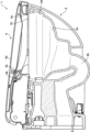
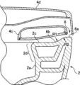
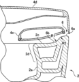
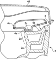
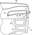
図4乃至図8は、本発明の実施形態の水洗大便器装置を、図2のIV-IV線乃至IIX-IIX線に沿って切断した断面において、せり上がり部を拡大して示す図である。ここで、図4は、水洗大便器装置1を、ボウル部2aの前端部近傍で切断した断面図であり、以下、図5乃至図8は、順に、ボウル部2aの後部側に近い位置で切断した断面を示している。
Next, the configuration of the raised portion provided on the toilet
Figures 4 to 8 are enlarged views of the raised portion of a flush toilet device according to an embodiment of the present invention, in cross-section taken along lines IV-IV to IIX-IIX in Figure 2. Here, Figure 4 is a cross-sectional view of the flush toilet device 1 taken near the front end of the
図2に示すように、便器本体2の便器上面2cには、その左右方向の両端に、上方に向けて隆起したせり上がり部6が設けられている。即ち、便器上面2cの左右方向の両端にせり上がり部6を設けることにより、便器上面2cの両端は、せり上がり、高くなっている。このせり上がり部6により、便器本体2の便器上面2cに温水洗浄便座4を配置する作業者は、視覚的に、そして手指の感触により、温水洗浄便座4を配置すべき正確な位置を認識することができ、作業性が向上する。また、温水洗浄便座4の本体部4aは、便器本体2上に配置された状態において、その一部が、便器上面2cに設けられたせり上がり部6の上端よりも下方に突出するように構成されている。
As shown in FIG. 2, the
ここで、便器本体2の便器上面2cは概ね平面であり、水平方向に向けられているのに対し、せり上がり部6の高さは、便器本体2の後方側が高くなるように構成されている。このため、せり上がり部6の上端は、水平面に対し、便器本体2の後方側が高くなるように傾斜し、せり上がり部6は、便器本体2の前方側から後方側に向けて、直線的に高さが高くなっている。そして、便器本体2の前端部付近では、せり上がり部6の高さはゼロに近くなり、便器本体2の前端部(便器上面2cの前方側の縁部の領域)にはせり上がり部6は設けられていない。このように、便器本体2の前端部にせり上がり部6が設けられていないことにより、せり上がり部6が、便器本体2の前方側から便器上面2cに温水洗浄便座4を配置する作業の邪魔にならず、作業性を向上させることができる。
Here, the
また、図4乃至図8に示すように、便座4cは、せり上がり部6の少なくとも一部を上方から覆うように配置されている。さらに、便座4cの底面に設けられた脚部4e(図5)により、便器本体2の便器上面2cと便座4cの底面の間に所定の隙間が形成されている。また、図4乃至図6に示すように、便座4cは、外周縁における厚さが、内周縁における厚さよりも薄くなるように構成されており、便器上面2cから隆起しているせり上がり部6が便座4cの底面と干渉しないようになっている。
As shown in Figures 4 to 8, the
さらに、図4乃至図8に示すように、せり上がり部6の上端には、概ね平坦に形成された平坦面6aが形成されている。このように、せり上がり部6の上端に平坦面6aを設けることにより、便器本体2の搬送時等に、せり上がり部6が損傷するのを防止することができる。
Furthermore, as shown in Figures 4 to 8, a
また、平坦面6aは、便器本体2の左右方向の断面図において、便器本体2の内方に向けて低くなるように傾斜している。このように、平坦面6aを内方に向けて低くなるように傾斜させることにより、便器上面2cに温水洗浄便座4を配置する際、作業者は手指の感触で温水洗浄便座4を配置すべき位置を認識することができ、容易に適正な位置に温水洗浄便座4を配置することができる。さらに、便器本体2の便器上面2cと、せり上がり部6の平坦面6aの間は、内傾斜面6bによって滑らかに接続されている。
Furthermore, the
この内傾斜面6bは、便器本体2の左右方向の断面図において、第1の曲率半径R1で凹状に湾曲している。さらに、平坦な平坦面6aと、凹状に湾曲した内傾斜面6bの間も滑らかに接続されており、この平坦面6aと内傾斜面6bを接続する部分(面)は、便器本体2の左右方向の断面図において、第2の曲率半径R2で丸められている。
This inner
ここで、凹状に湾曲した内傾斜面6bの有する第1の曲率半径R1は、図4から図8にかけて次第に小さくなっている。即ち、第1の曲率半径R1は、便器本体2の前方側よりも、後方側が徐々に小さくなるように構成されている。このように、内傾斜面6bの第1の曲率半径R1を後方側において小さくすることにより、温水洗浄便座4の本体部4aを配置すべき左右方向の位置が、より明確となり、温水洗浄便座4を適正な位置に配置しやすくなる。なお、本実施形態において、内傾斜面6bの第1の曲率半径R1は、内傾斜面6bと平坦面6aを接続する第2の曲率半径R2の2倍以上の大きさに構成されている。
Here, the first radius of curvature R1 of the concavely curved inner
本発明の実施形態の水洗大便器装置1によれば、便器本体2の便器上面2cに、左右方向の両端にせり上がり部6が設けられている(図2)ので、温水洗浄便座4を便器本体2の上に配置する際、作業者は、温水洗浄便座4を配置すべき適正な位置を容易に認識することができる。これにより、温水洗浄便座4を便器本体2の上に配置する作業の作業性を向上させることができる。
According to the flush toilet device 1 of the embodiment of the present invention, the toilet
また、本実施形態の水洗大便器装置1によれば、せり上がり部6が、便器本体2の前方側よりも後方側が高くなるように構成されている(図2)ので、温水洗浄便座4の後方側に設けられた本体部4aの位置を、より正確に位置決めすることができ、温水洗浄便座4を配置する作業の作業性を更に向上させることができる。
In addition, according to the flush toilet device 1 of this embodiment, the raised
さらに、本実施形態の水洗大便器装置1によれば、せり上がり部6が、前方側から後方側に向けて、直線的に高さが高くされている(図2)ので、温水洗浄便座4を配置する際、温水洗浄便座4の前部を把持した作業者の手と、せり上がり部6が干渉しにくく、温水洗浄便座4を配置する作業の作業性を、より向上させることができる。
Furthermore, according to the flush toilet device 1 of this embodiment, the raised
また、本実施形態の水洗大便器装置1によれば、せり上がり部6が便器本体2の前端部に設けられていない(図2)ので、温水洗浄便座4を便器本体2の前方側から、適正位置に配置する際、温水洗浄便座4とせり上がり部6が干渉しにくく、温水洗浄便座4を配置する作業の作業性を、更に向上させることができる。
In addition, with the flush toilet device 1 of this embodiment, the raised
さらに、本実施形態の水洗大便器装置1によれば、せり上がり部6の上端に平坦面6aが形成されている(図4乃至図8)ので、便器本体2の製造時や、運搬時において、突出しているせり上がり部6が損傷されるのを防止することができる。
Furthermore, according to the flush toilet device 1 of this embodiment, a
また、本実施形態の水洗大便器装置1によれば、せり上がり部6の平坦面6aが便器本体2の内方に向けて低くなるように傾斜している(図4乃至図8)ので、温水洗浄便座4を便器本体2の上に配置する作業が平坦面6aによっても案内され、温水洗浄便座4を配置する作業の作業性を、更に向上させることができる。
In addition, according to the flush toilet device 1 of this embodiment, the
さらに、本実施形態の水洗大便器装置1によれば、平坦面6aと便器上面2cとを接続する内傾斜面6bがせり上がり部6に形成されている(図4乃至図8)ので、温水洗浄便座4を便器本体2の上に配置する作業が内傾斜面6bによっても案内され、温水洗浄便座4を配置する作業の作業性を、より向上させることができる。
Furthermore, according to the flush toilet device 1 of this embodiment, an inner
また、本実施形態の水洗大便器装置1によれば、せり上がり部6の内傾斜面6bが、第1の曲率半径R1で凹状に湾曲している(図4乃至図8)ので、温水洗浄便座4を便器本体2の上に配置する作業が内傾斜面6bによって滑らかに案内され、温水洗浄便座4を配置する作業の作業性を向上させることができる。
In addition, according to the flush toilet device 1 of this embodiment, the inner
さらに、本実施形態の水洗大便器装置1によれば、せり上がり部6の内傾斜面6bの第1の曲率半径R1が、内傾斜面6bと平坦面6aを接続する面の第2の曲率半径R2の2倍以上大きく構成されているので、温水洗浄便座4を便器本体2の上に配置する作業を、より滑らかに案内することができ、温水洗浄便座4を配置する作業の作業性を向上させることができる。
Furthermore, according to the flush toilet device 1 of this embodiment, the first radius of curvature R1 of the inner
また、本実施形態の水洗大便器装置1によれば、内傾斜面6bの第1の曲率半径R1が、便器本体2の前方側よりも、後方側が小さくなるように構成されているので、温水洗浄便座4を配置する作業において、温水洗浄便座4の後部が、より厳密に案内され、温水洗浄便座4後部の本体部4aを、より正確に位置決めすることができる。
In addition, according to the flush toilet device 1 of this embodiment, the first radius of curvature R1 of the inner
以上、本発明の実施形態の水洗大便器装置1を説明したが、上述した実施形態に種々の変更を加えることができる。特に、上述した実施形態においては、本発明を壁掛け式の水洗大便器装置1に適用していたが、床置き式の水洗大便器装置に本発明を適用することもできる。また、上述した実施形態においては、水洗大便器装置1を設置した壁面Wから延びる給水管、電源コードが、便器本体2の内部を通って、温水洗浄便座4の本体部4aに接続されていた。しかしながら、壁面又は床面から延びる給水管及び/又は電源コードが、便器本体の外部を通って温水洗浄便座に接続される水洗大便器装置に本発明を適用することもできる。
Although the flush toilet device 1 according to the embodiment of the present invention has been described above, various modifications can be made to the above-mentioned embodiment. In particular, in the above-mentioned embodiment, the present invention is applied to a wall-hung flush toilet device 1, but the present invention can also be applied to a floor-standing flush toilet device. Also, in the above-mentioned embodiment, the water supply pipe and power cord extending from the wall surface W on which the flush toilet device 1 is installed pass through the inside of the
1 水洗大便器装置
2 便器本体
2a ボウル部
2b 排水トラップ管路
2c 便器上面
2d リム部
2e リム吐水口
2f 開口部
4 温水洗浄便座
4a 本体部
4b 洗浄ノズル
4c 便座
4d 便座カバー
4e 脚部
6 せり上がり部
6a 平坦面
6b 内傾斜面
1
Claims (9)
上記便器本体は、
汚物を受けるボウル部と、
このボウル部の上端に連なり、上記ボウル部を囲むように形成された便器上面と、
上記ボウル部の底部に連通した排水トラップ管路と、を備え、
上記温水洗浄便座は、
本体部と、
この本体部から進退可能に設けられ、洗浄水を噴射する洗浄ノズルと、
上記本体部に対して回動可能に取り付けられ、上記ボウル部を取り囲むように上記便器上面の上に載置される便座と、を備え、
上記便器上面の左右方向の両端には、上方に向けて隆起したせり上がり部が設けられ、上記温水洗浄便座の上記本体部の一部は上記便器本体の上記せり上がり部の上端よりも下方に突出するように構成され、
上記せり上がり部は、上記便器本体の前方側から後方側に向けて、直線的に高さが高くなるように構成されていることを特徴とする水洗大便器装置。 A flush toilet apparatus having a toilet body and a warm water cleaning toilet seat disposed on the toilet body,
The toilet body is
A bowl portion for receiving waste;
a toilet upper surface formed to be connected to the upper end of the bowl portion and to surround the bowl portion;
a drain trap pipe communicating with the bottom of the bowl portion;
The above warm water washing toilet seat is
A main body portion,
a cleaning nozzle provided retractably from the main body and configured to spray cleaning water;
a toilet seat that is rotatably attached to the main body and placed on the upper surface of the toilet bowl so as to surround the bowl portion;
A raised portion that is raised upward is provided at both left and right ends of the upper surface of the toilet, and a part of the main body of the warm water washing toilet seat is configured to protrude downward beyond the upper end of the raised portion of the toilet main body ,
A flush toilet apparatus characterized in that the raised portion is configured to increase in height linearly from the front side to the rear side of the toilet body .
Priority Applications (4)
| Application Number | Priority Date | Filing Date | Title |
|---|---|---|---|
| JP2023030034A JP7621606B2 (en) | 2023-02-28 | 2023-02-28 | Flush toilet equipment |
| CN202311452146.5A CN118563889A (en) | 2023-02-28 | 2023-11-03 | Flush toilet device |
| US18/396,264 US12473729B2 (en) | 2023-02-28 | 2023-12-26 | Flush toilet apparatus |
| EP24157553.9A EP4424936A1 (en) | 2023-02-28 | 2024-02-14 | Flush toilet apparatus |
Applications Claiming Priority (1)
| Application Number | Priority Date | Filing Date | Title |
|---|---|---|---|
| JP2023030034A JP7621606B2 (en) | 2023-02-28 | 2023-02-28 | Flush toilet equipment |
Publications (2)
| Publication Number | Publication Date |
|---|---|
| JP2024122474A JP2024122474A (en) | 2024-09-09 |
| JP7621606B2 true JP7621606B2 (en) | 2025-01-27 |
Family
ID=89941260
Family Applications (1)
| Application Number | Title | Priority Date | Filing Date |
|---|---|---|---|
| JP2023030034A Active JP7621606B2 (en) | 2023-02-28 | 2023-02-28 | Flush toilet equipment |
Country Status (4)
| Country | Link |
|---|---|
| US (1) | US12473729B2 (en) |
| EP (1) | EP4424936A1 (en) |
| JP (1) | JP7621606B2 (en) |
| CN (1) | CN118563889A (en) |
Citations (5)
| Publication number | Priority date | Publication date | Assignee | Title |
|---|---|---|---|---|
| JP2006009364A (en) | 2004-06-24 | 2006-01-12 | Matsushita Electric Works Ltd | Toilet stool |
| JP2015007313A (en) | 2013-06-24 | 2015-01-15 | パナソニック株式会社 | Toilet bowl device |
| JP2018123632A (en) | 2017-02-03 | 2018-08-09 | Toto株式会社 | Toilet device |
| JP2018123621A (en) | 2017-02-02 | 2018-08-09 | Toto株式会社 | Sanitary washing device and assembly method of the same |
| JP2021107628A (en) | 2019-12-27 | 2021-07-29 | 株式会社Lixil | Toilet bowl device |
Family Cites Families (21)
| Publication number | Priority date | Publication date | Assignee | Title |
|---|---|---|---|---|
| JPS5032022Y2 (en) * | 1973-08-31 | 1975-09-18 | ||
| US4242764A (en) * | 1978-09-20 | 1981-01-06 | Mamoru Fukuda | Hygienic cleaning apparatus |
| DE2912084C2 (en) * | 1979-03-27 | 1983-01-05 | Heinz Georg Thun Baus | Water closet |
| JPS58120287A (en) | 1982-01-11 | 1983-07-18 | 株式会社東芝 | Liquid crystal display |
| JPS58120287U (en) * | 1982-02-12 | 1983-08-16 | ナショナル住宅産業株式会社 | toilet bowl |
| JPS59130595U (en) * | 1983-02-19 | 1984-09-01 | 東陶機器株式会社 | bidet |
| US5987659A (en) * | 1996-05-20 | 1999-11-23 | Cannizzaro; Carl C. | Bidet device providing repeatable solution treatments |
| US6105179A (en) * | 1999-02-22 | 2000-08-22 | Burns; Robert Raymond | Toilet/bidet seat |
| US20050028263A1 (en) * | 2003-08-08 | 2005-02-10 | Josef Wodeslavsky | Water and space conservation toilet/bidet combination |
| US7284285B2 (en) * | 2005-02-01 | 2007-10-23 | Saverio Scalzi | Toilet and bidet system |
| TW200738941A (en) * | 2006-02-10 | 2007-10-16 | Toto Ltd | Sanitary washing toilet seat device, and toilet device |
| US7461414B2 (en) * | 2006-10-18 | 2008-12-09 | Santa Cruz Cathy D | Simplified bidet assembly for use with a conventional toilet |
| WO2008140105A1 (en) * | 2007-05-15 | 2008-11-20 | Toto Ltd. | Sanitary flushing device |
| US8108953B2 (en) * | 2009-07-26 | 2012-02-07 | Pin Zeng | Toilet warm water and air ejection device |
| EP2305903A1 (en) * | 2009-09-28 | 2011-04-06 | Toto Ltd. | Washing device for user's private parts |
| DE202010003453U1 (en) | 2010-03-11 | 2010-08-19 | Inhaber Alfred Spannring | Toilet bowl (ceramic) for shower toilet |
| JP6667097B2 (en) | 2015-11-12 | 2020-03-18 | Toto株式会社 | Flush toilet |
| KR102505685B1 (en) | 2017-01-16 | 2023-03-02 | 가부시키가이샤 한도오따이 에네루기 켄큐쇼 | Display device and manufacturing method thereof |
| JP6593717B2 (en) | 2017-01-30 | 2019-10-23 | Toto株式会社 | Wall-mounted toilet device and toilet system |
| CN108374466B (en) | 2017-01-30 | 2020-07-14 | Toto株式会社 | Mounting device for wall-mounted toilet and toilet flushing system |
| CN207959409U (en) | 2018-01-09 | 2018-10-12 | 松下家电研究开发(杭州)有限公司 | A kind of integral type toilet seat |
-
2023
- 2023-02-28 JP JP2023030034A patent/JP7621606B2/en active Active
- 2023-11-03 CN CN202311452146.5A patent/CN118563889A/en active Pending
- 2023-12-26 US US18/396,264 patent/US12473729B2/en active Active
-
2024
- 2024-02-14 EP EP24157553.9A patent/EP4424936A1/en active Pending
Patent Citations (5)
| Publication number | Priority date | Publication date | Assignee | Title |
|---|---|---|---|---|
| JP2006009364A (en) | 2004-06-24 | 2006-01-12 | Matsushita Electric Works Ltd | Toilet stool |
| JP2015007313A (en) | 2013-06-24 | 2015-01-15 | パナソニック株式会社 | Toilet bowl device |
| JP2018123621A (en) | 2017-02-02 | 2018-08-09 | Toto株式会社 | Sanitary washing device and assembly method of the same |
| JP2018123632A (en) | 2017-02-03 | 2018-08-09 | Toto株式会社 | Toilet device |
| JP2021107628A (en) | 2019-12-27 | 2021-07-29 | 株式会社Lixil | Toilet bowl device |
Also Published As
| Publication number | Publication date |
|---|---|
| CN118563889A (en) | 2024-08-30 |
| US20240287780A1 (en) | 2024-08-29 |
| EP4424936A1 (en) | 2024-09-04 |
| US12473729B2 (en) | 2025-11-18 |
| JP2024122474A (en) | 2024-09-09 |
Similar Documents
| Publication | Publication Date | Title |
|---|---|---|
| WO2005085538A1 (en) | Flush toilet bowl | |
| EP3551809B1 (en) | Toilet for use while squatting | |
| JP7483216B2 (en) | Flush toilet | |
| JP7621606B2 (en) | Flush toilet equipment | |
| JP2018141317A (en) | Water closet | |
| JP7778112B2 (en) | flush toilet | |
| JP2018080504A (en) | Flush toilet | |
| JP2007314975A (en) | Western-style toilet bowl equipment | |
| JP7660538B2 (en) | Flush toilet | |
| JP4599716B2 (en) | Local cleaning equipment | |
| JP4141153B2 (en) | Toilet bowl equipment | |
| JP4863458B2 (en) | Sanitary washing device and toilet device | |
| JP7499145B2 (en) | Sanitary cleaning device and toilet device | |
| JPH09125504A (en) | Western style stool | |
| JP4889099B2 (en) | Sanitary washing device and toilet device | |
| JP2004084473A (en) | Flush toilet bowl | |
| JP2024122475A (en) | Flush toilet equipment | |
| JP2002294837A (en) | Flush toilet bowl | |
| JP3212338U (en) | Western-style toilet | |
| JP7733988B2 (en) | Sanitary Cleaning Device | |
| JPH0723075U (en) | Sanitary washing equipment | |
| JP2002266412A (en) | Flush toilet | |
| JP7435029B2 (en) | flush toilet | |
| KR200426389Y1 (en) | Toilet seat with urine splash prevention aid | |
| US20250376837A1 (en) | Toilet arrangement for swirl flushing |
Legal Events
| Date | Code | Title | Description |
|---|---|---|---|
| A621 | Written request for application examination |
Free format text: JAPANESE INTERMEDIATE CODE: A621 Effective date: 20240718 |
|
| A871 | Explanation of circumstances concerning accelerated examination |
Free format text: JAPANESE INTERMEDIATE CODE: A871 Effective date: 20240718 |
|
| A131 | Notification of reasons for refusal |
Free format text: JAPANESE INTERMEDIATE CODE: A131 Effective date: 20240815 |
|
| A521 | Request for written amendment filed |
Free format text: JAPANESE INTERMEDIATE CODE: A523 Effective date: 20241011 |
|
| TRDD | Decision of grant or rejection written | ||
| A01 | Written decision to grant a patent or to grant a registration (utility model) |
Free format text: JAPANESE INTERMEDIATE CODE: A01 Effective date: 20241216 |
|
| A61 | First payment of annual fees (during grant procedure) |
Free format text: JAPANESE INTERMEDIATE CODE: A61 Effective date: 20241229 |
|
| R150 | Certificate of patent or registration of utility model |
Ref document number: 7621606 Country of ref document: JP Free format text: JAPANESE INTERMEDIATE CODE: R150 |