JP7619981B2 - Scroll compressor and heat pump water heater - Google Patents
Scroll compressor and heat pump water heater Download PDFInfo
- Publication number
- JP7619981B2 JP7619981B2 JP2022094219A JP2022094219A JP7619981B2 JP 7619981 B2 JP7619981 B2 JP 7619981B2 JP 2022094219 A JP2022094219 A JP 2022094219A JP 2022094219 A JP2022094219 A JP 2022094219A JP 7619981 B2 JP7619981 B2 JP 7619981B2
- Authority
- JP
- Japan
- Prior art keywords
- suction
- oil
- scroll
- orbiting
- back pressure
- Prior art date
- Legal status (The legal status is an assumption and is not a legal conclusion. Google has not performed a legal analysis and makes no representation as to the accuracy of the status listed.)
- Active
Links
Images


Landscapes
- Rotary Pumps (AREA)
Description
本発明は空調用や給湯用或いは冷凍用などの冷凍サイクル装置に使用されるスクロール圧縮機及びヒートポンプ式給湯機に関する。 The present invention relates to scroll compressors and heat pump water heaters used in refrigeration cycle devices such as air conditioning, hot water supply, and refrigeration.
空調用や給湯用或いは冷凍用などの冷凍サイクル装置に使用されるスクロール圧縮機としては、特許第6143862号公報(特許文献1)に記載されたものなどがある。この特許文献1のものには、台板に渦巻状のラップを立設した固定スクロールと、鏡板に渦巻状のラップを立設し前記固定スクロールと噛み合わされて旋回運動をすることにより吸込室または圧縮室を形成する旋回スクロールと、前記旋回スクロールに前記固定スクロール側への押付力を付与する背圧室と、この背圧室の背圧を調整するための背圧弁と、この背圧弁の入口側と前記背圧室を連通する背圧弁流入路と、前記背圧弁の出口側と前記吸込室または圧縮室を連通する背圧弁流出路を備えたスクロール圧縮機が記載されている。
Scroll compressors used in refrigeration cycle devices for air conditioning, hot water supply, refrigeration, etc. include those described in Japanese Patent No. 6143862 (Patent Document 1). This
また、前記背圧弁流出路の前記吸込室または圧縮室への流路出口部の少なくとも一部は、前記固定スクロールのラップ歯先の位置よりも歯底側に形成されると共に、前記背圧弁流出路における流路入口側の断面積よりも流路出口側の断面積を大きく形成することにより、前記背圧弁流出路の流路出口部の一部が、固定スクロールのラップ歯先の位置よりも歯底側となるようにすることが記載されている。 It also describes that at least a part of the flow passage outlet of the back pressure valve outflow passage to the suction chamber or compression chamber is formed closer to the tooth bottom than the position of the wrap tooth tip of the fixed scroll, and that by forming the cross-sectional area of the flow passage outlet side of the back pressure valve outflow passage larger than the cross-sectional area of the flow passage inlet side, a part of the flow passage outlet of the back pressure valve outflow passage is made closer to the tooth bottom than the position of the wrap tooth tip of the fixed scroll.
特許文献1のものは、前記背圧弁流出路(給油経路)における流路出口側の断面積を流路入口側の断面積よりも大きく形成することにより、背圧室から吸込室または圧縮室に流入する油を、固定スクロールのラップ歯先側だけでなく、固定スクロール歯底と旋回スクロールのラップ歯先とのすき間へも供給することが記載されている。
しかし、スクロール圧縮機の構造上の制約から、給油経路における流路出口側の断面積を大きく形成しても、流路出口部から吸込室に流出する油の経路上に、スクロール圧縮機の吸込口が存在すると、吸込口から吸入された軸方向のガス流れにより、固定スクロールのラップ歯底側に向かう油の流れが押さえ付けられてしまい、固定スクロールのラップ歯底側への給油を十分に行うことができない。このため、固定スクロールのラップ歯底と旋回スクロールのラップ歯先との隙間への給油が不足してシール性が低下し、体積効率が低下することによりスクロール圧縮機の効率低下を招くという課題がある。 However, due to structural constraints of the scroll compressor, even if the cross-sectional area of the oil supply path on the outlet side of the flow passage is made large, if the suction port of the scroll compressor is on the path of the oil flowing from the outlet of the flow passage to the suction chamber, the axial gas flow sucked in from the suction port will suppress the flow of oil toward the wrap tooth bottom side of the fixed scroll, and oil cannot be sufficiently supplied to the wrap tooth bottom side of the fixed scroll. This causes an issue of insufficient oil supply to the gap between the wrap tooth bottom of the fixed scroll and the wrap tooth tip of the orbiting scroll, reducing sealing performance and reducing volumetric efficiency, which leads to a decrease in the efficiency of the scroll compressor.
本発明の目的は、固定スクロールのラップ歯底側への給油を確保し、固定スクロールのラップ歯底と旋回スクロールのラップ歯先との隙間のシール性を向上させて効率向上を図ることのできるスクロール圧縮機及びヒートポンプ式給湯機を得ることにある。 The object of the present invention is to provide a scroll compressor and a heat pump water heater that can ensure oil supply to the wrap tooth bottom side of the fixed scroll and improve the sealing of the gap between the wrap tooth bottom of the fixed scroll and the wrap tooth tip of the orbiting scroll, thereby improving efficiency.
上記目的を達成するため、本発明は、固定鏡板に渦巻状の固定ラップを立設した固定スクロールと、旋回鏡板に立設した渦巻状の旋回ラップを有し前記固定スクロールと噛み合わされて旋回運動をする旋回スクロールと、前記固定スクロール及び旋回スクロールを互いに噛み合わせて形成される吸込室及び圧縮室と、前記旋回スクロールを旋回運動させるためのクランク軸と、前記旋回スクロールの旋回ボス部に設けられ前記クランク軸の偏心ピン部に対し前記旋回スクロールを軸方向に移動可能でかつ回転自在に支持するための旋回軸受と、前記旋回ボス部には密閉容器内に貯留された潤滑油が導かれて吐出圧力に近い圧力となる旋回ボス部内空間と、前記旋回スクロールの背面で前記旋回ボス部内空間よりも外周側に設けられ吐出圧力と吸込圧力との間の圧力となる背圧室と、前記固定スクロールの固定鏡板外周側に設けられ、吸込パイプからの冷媒ガスが導かれる吸込口を備えるスクロール圧縮機であって、前記吸込口と前記吸込室との間の前記固定鏡板に設けられた吸込部と、前記吸込口における前記吸込パイプとは反対側に設けられ、吸込パイプからの冷媒ガスの流れを斜め流れに偏向させる壁部材と、前記旋回鏡板の外周側に設けられ、前記背圧室の油が導かれる給油凹部と、前記固定鏡板に設けられ、前記給油凹部の油を前記吸込部側に導く吸込溝と、前記吸込溝の出口側に形成され、前記吸込溝からの油の少なくとも一部を前記旋回ラップの歯先側に吐出させるためのテーパ形状部と、を備え、前記吸込溝の吸込部側開口部を前記壁部材の背面側に開口させ、前記壁部材が、前記吸込パイプから流入する冷媒ガスに対し、前記吸込溝から流出する油の傘となるように構成されていることを特徴とする。 In order to achieve the above object, the present invention provides a fixed scroll having a spiral fixed wrap standing on a fixed end plate, an orbiting scroll having a spiral orbiting wrap standing on a rotating end plate and meshing with the fixed scroll to perform orbital motion, a suction chamber and a compression chamber formed by meshing the fixed scroll and the orbiting scroll with each other, a crankshaft for orbiting the orbiting scroll, an orbiting bearing provided in the orbiting boss of the orbiting scroll for supporting the orbiting scroll axially movable and rotatably relative to the eccentric pin of the crankshaft, an internal space of the orbiting boss to which lubricating oil stored in a sealed container is introduced and which is held at a pressure close to the discharge pressure, a back pressure chamber provided on the back surface of the orbiting scroll and closer to the outer periphery than the internal space of the orbiting boss and which is held at a pressure between the discharge pressure and the suction pressure, and a fixed end plate of the fixed scroll. A scroll compressor having an intake port provided on the outer periphery of the plate and through which refrigerant gas is guided from a suction pipe, the scroll compressor is characterized in that it is provided with an intake section provided on the fixed end plate between the intake port and the suction chamber, a wall member provided on the opposite side of the intake port from the suction pipe and deflecting the flow of refrigerant gas from the suction pipe to an oblique flow, an oil supply recess provided on the outer periphery of the rotating end plate and through which oil from the back pressure chamber is guided, an intake groove provided on the fixed end plate and guiding the oil from the oil supply recess to the intake section side, and a tapered portion formed on the outlet side of the intake groove for discharging at least a portion of the oil from the intake groove to the tooth tip side of the rotating wrap, and the intake section side opening of the intake groove is opened on the back side of the wall member, and the wall member is configured to form an umbrella of oil flowing out of the suction groove against the refrigerant gas flowing in from the suction pipe.
本発明の他の特徴は、固定鏡板に渦巻状の固定ラップを立設した固定スクロールと、旋回鏡板に立設した渦巻状の旋回ラップを有し前記固定スクロールと噛み合わされて旋回運動をする旋回スクロールと、前記固定スクロール及び旋回スクロールを互いに噛み合わせて形成される吸込室及び圧縮室と、前記旋回スクロールを旋回運動させるためのクランク軸と、前記旋回スクロールの旋回ボス部に設けられ前記クランク軸の偏心ピン部に対し前記旋回スクロールを軸方向に移動可能でかつ回転自在に支持するための旋回軸受と、前記旋回ボス部には密閉容器内に貯留された潤滑油が導かれて吐出圧力に近い圧力となる旋回ボス部内空間と、前記旋回スクロールの背面で前記旋回ボス部内空間よりも外周側に設けられ吐出圧力と吸込圧力との間の圧力となる背圧室と、前記固定スクロールの固定鏡板外周側に設けられ、吸込パイプからの冷媒ガスが導かれる吸込口を備えるスクロール圧縮機であって、前記吸込口と前記吸込室との間の前記固定鏡板に設けられた吸込部と、前記吸込口における前記吸込パイプとは反対側に設けられ、吸込パイプからの冷媒ガスの流れを斜め流れに偏向させる壁部材と、前記旋回鏡板の外周側に設けられ、前記背圧室の油が導かれる給油凹部と、前記固定鏡板に設けられ、前記給油凹部の油を前記壁部材の上流側における前記吸込口に吐出する給油経路を設けていることにある。 Other features of the present invention include a fixed scroll having a spiral-shaped fixed wrap standing on a fixed end plate, an orbiting scroll having a spiral-shaped orbiting wrap standing on a orbiting end plate and meshing with the fixed scroll to perform orbital motion, a suction chamber and a compression chamber formed by meshing the fixed scroll and the orbiting scroll with each other, a crankshaft for orbiting the orbiting scroll, an orbiting bearing provided in the orbiting boss of the orbiting scroll for supporting the orbiting scroll axially movable and rotatable relative to the eccentric pin of the crankshaft, a space in the orbiting boss into which lubricating oil stored in a sealed container is introduced and the pressure in the orbiting boss is close to the discharge pressure, and A scroll compressor having a back pressure chamber that is located on the outer periphery of the space inside the rotating boss and has a pressure between the discharge pressure and the suction pressure, and an intake port that is located on the outer periphery of the fixed end plate of the fixed scroll and through which refrigerant gas is guided from a suction pipe, and the compressor has a suction section that is located on the fixed end plate between the suction port and the suction chamber, a wall member that is located on the opposite side of the suction pipe at the suction port and deflects the flow of refrigerant gas from the suction pipe to an oblique flow, an oil supply recess that is located on the outer periphery of the rotating end plate and through which oil from the back pressure chamber is guided, and an oil supply path that is located on the fixed end plate and discharges the oil from the oil supply recess to the suction port on the upstream side of the wall member.
本発明の更に他の特徴は、湯の沸き上げを行うヒートポンプユニット部と、湯を溜める貯湯タンクユニット部を備え、前記ヒートポンプユニット部は、スクロール圧縮機と、このスクロール圧縮機から吐出された高温高圧冷媒と被加熱媒体である水とを熱交換させる水-冷媒熱交換器と、この水-冷媒熱交換器から流出した冷媒を低温低圧に膨張させる膨張手段と、膨張手段から流出した低温低圧冷媒を蒸発させる空気側熱交換器とを備え、前記スクロール圧縮機は上述したスクロール圧縮機を採用しているヒートポンプ式給湯機にある。 Another feature of the present invention is that it is a heat pump water heater that includes a heat pump unit that heats up hot water and a hot water tank unit that stores hot water, the heat pump unit including a scroll compressor, a water-refrigerant heat exchanger that exchanges heat between the high-temperature, high-pressure refrigerant discharged from the scroll compressor and water, which is the medium to be heated, an expansion means that expands the refrigerant that flows out of the water-refrigerant heat exchanger to a low-temperature, low-pressure refrigerant, and an air-side heat exchanger that evaporates the low-temperature, low-pressure refrigerant that flows out of the expansion means, and the scroll compressor is a scroll compressor as described above.
本発明によれば、固定スクロールのラップ歯底側への給油を確保し、固定スクロールのラップ歯底と旋回スクロールのラップ歯先との隙間のシール性を向上させて効率向上を図ることのできるスクロール圧縮機及びヒートポンプ式給湯機を得ることができる効果がある。 The present invention has the effect of providing a scroll compressor and a heat pump water heater that can ensure oil supply to the wrap tooth bottom side of the fixed scroll and improve the sealing of the gap between the wrap tooth bottom of the fixed scroll and the wrap tooth tip of the orbiting scroll, thereby improving efficiency.
以下、本発明のスクロール圧縮機の具体的実施例を、図面に基づいて説明する。なお、各図において、同一符号を付した部分は同一或いは相当する部分を示している。 Below, specific examples of the scroll compressor of the present invention will be described with reference to the drawings. Note that in each drawing, parts with the same reference numerals indicate the same or corresponding parts.
本発明のスクロール圧縮機の実施例1を図1~図6を用いて説明する。
まず、図1、図2により、本実施例のスクロール圧縮機の全体構成を説明する。図1は本発明のスクロール圧縮機の実施例1を示す縦断面図、図2は固定スクロールに旋回スクロールを配した状態を示す固定スクロールの下面図である。
A scroll compressor according to a first embodiment of the present invention will be described with reference to FIGS.
First, the overall configuration of the scroll compressor of the present embodiment will be described with reference to Figures 1 and 2. Figure 1 is a vertical sectional view showing a scroll compressor according to a first embodiment of the present invention, and Figure 2 is a bottom view of a fixed scroll showing a state in which an orbiting scroll is disposed on the fixed scroll.
スクロール圧縮機1は、密閉容器8内に、圧縮機構部1A及びモータ部7などを収容して構成されている。
前記圧縮機構部1Aは、フレーム4に固定された固定スクロール2に旋回スクロール3が噛み合わされて圧縮室10が形成され、前記モータ部7の回転により、クランク軸(回転軸)6を介して前記旋回スクロール3を旋回運動させることにより、前記圧縮室10の容積を減少させて圧縮動作を行う。
The
The compression mechanism 1A has a
この圧縮動作に伴って、作動流体(冷媒)が吸込パイプ12から吸込口2sを経て吸込室16(図2参照)へ吸込まれ、吸込まれた作動流体は圧縮室10での圧縮行程を経て、吐出口2dから密閉容器8内の固定背面室である吐出空間11に吐出される。この吐出空間11に吐出された作動流体は、前記固定スクロール2の外周と前記フレーム4の外周に形成された通路(図示せず)を通って、モータ室9側に流れ、その後吐出パイプ13から密閉容器8外に吐出されるように構成されている。
As a result of this compression operation, the working fluid (refrigerant) is sucked from the
前記固定スクロール2は、固定鏡板2a、この固定鏡板2aに渦巻状に立設された固定ラップ2b、前記固定鏡板2aの外周側に位置し、前記固定ラップ2bの先端面とほぼ同じ高さの固定鏡板面2uを有して固定ラップ2bを囲むように筒状に設けられた支持部2cを備えている。前記固定ラップ2bが立設された固定鏡板2aの表面は、固定ラップ2bの間にあるため、歯底と呼ばれる。
The
前記固定鏡板面2uは、固定スクロール2の支持部2cが、旋回スクロール3の旋回鏡板3aと接する摺動面となっている。固定スクロール2は、前記支持部2cをボルト等により前記フレーム4に固定しており、固定スクロール2と一体に結合された前記フレーム4は溶接等の固定手段により前記密閉容器8に固定されている。
The fixed
前記旋回スクロール3は、固定スクロール2に対向して配置され、固定スクロール2の固定ラップ2bと旋回スクロール3の旋回ラップ3bとが噛み合わされて、フレーム4内に旋回可能に設けられている。この旋回スクロール3は、円板状の旋回鏡板3aの表面である歯底から立設された渦巻状の旋回ラップ3b、及び前記旋回鏡板3aの背面中央に設けられた旋回ボス部(ボス部)3cを有する。また、前記旋回鏡板3aの外周部の前記固定スクロール2と接する表面は、旋回スクロール3の旋回鏡板上面3a1(図3参照)となっている。
The orbiting
前記旋回スクロール3の旋回ラップ3bの先端部(ラップ歯先)は前記固定スクロール2の歯底と微小すき間をもって相対するように構成されている。同様に、固定スクロール2の固定ラップ2bの先端部(ラップ歯先)も前記旋回スクロール3の歯底と微小すき間をもって相対するように構成されている。
The tip (wrap tooth tip) of the orbiting
前記圧縮機構部1A及びモータ部7等を収容している前記密閉容器8の底部には、冷凍機油としての潤滑油(以下、単に油ともいう)を溜める貯油部8dが設けられている。前記モータ部7はロータ7aとステータ7bにより構成され、前記ロータ7aには前記クランク軸6が一体に固定されている。このクランク軸6は前記フレーム4に主軸受14を介して回転自在に支持されている。
The bottom of the sealed
前記クランク軸6の先端には偏心したピン部(偏心ピン部)6aが設けられており、このピン部6aは、前記旋回スクロール3の旋回ボス部3cに設けられた旋回軸受15に挿入され、前記旋回スクロール3はクランク軸6の回転に伴い旋回可能に構成されている。
The tip of the
前記旋回スクロール3の中心軸線は、前記固定スクロール2の中心軸線に対して所定距離だけ偏心した状態となる。5は、前記旋回スクロール3を前記固定スクロール2に対して、自転しないように拘束しながら相対的に旋回運動させるためのオルダムリングである。
The central axis of the orbiting
前記密閉容器8は、中央の円筒状の胴部8aと、胴部8aの上部を塞ぐ蓋キャップ8bと、胴部8aの下部を塞ぐ底キャップ8cから構成されている。30は前記蓋キャップ8bに設けられた電源端子である。また、前記ロータ7aの上部にはカウンタウエイト35が、ロータ7aの下部にはカウンタウエイト36が設けられている。
The sealed
25は前記クランク軸6の下部を支持する副軸受で、この副軸受25は、軸受ブッシュ25aと、軸受ブッシュ25aを収容する副軸受ハウジング25bを備え、副軸受ハウジング25bは、前記密閉容器8の下部側に固定された副フレーム26に固定されている。
25 is a secondary bearing that supports the lower part of the
前記モータ部7により前記クランク軸6を回転させると、旋回スクロール3は、固定スクロール2の中心軸線を中心に、所定の旋回半径をもって旋回運動する。これにより、冷凍サイクルの冷媒(冷媒ガス)が吸込パイプ12から流入し、固定スクロール2に形成されている吸込口2sから、図2に示す吸込部17を通って、固定ラップ2bと旋回ラップ3bで形成された吸込室16に流入する。前記吸込部17は前記吸込口2sと前記吸込室16との間に形成され、前記吸込口2sからの冷媒ガス(流入ガス)を前記吸込室16に導くための空間である。
When the
冷媒ガスは吸込室16から圧縮室10に取り込まれ、旋回スクロール3の旋回運動と共に圧縮室10の容積は減少して冷媒ガスは圧縮される。圧縮された冷媒ガスは吐出口2dから吐出空間11に吐出され、その後モータ室9側に流れる。この過程で冷媒中に含まれている油は分離されて前記貯油部8dに溜まる。油を分離された冷媒は吐出パイプ13から、ヒートポンプ式給湯機や空調装置などの冷凍サイクルの凝縮器側に流出する。
Refrigerant gas is taken into the
前記貯油部8dの油の流れについて説明する。前記クランク軸6の下端には、給油パイプ6cが設けられており、密閉容器8底部の貯油部8dに溜められた潤滑油は吐出圧力であり、この吐出圧力下の潤滑油は前記給油パイプ6cから流入して、前記クランク軸6内に軸方向に貫通するように形成されている給油穴6bを通って、前記ピン部6a上端の旋回ボス部3c内の空間である旋回ボス部内空間(旋回軸受室)19へ送られる。
The flow of oil in the
なお、前記給油穴6bを流れる潤滑油の一部は、前記クランク軸6に設けられている横穴を介して副軸受25や主軸受14に供給され、副軸受25を潤滑した油は、密閉容器8底部の前記貯油部8dに戻る。前記主軸受14を潤滑した油は前記貯油部8dに戻されるか、背圧室18に流入する。
A portion of the lubricating oil flowing through the
前記給油穴6bを流れるその他の大部分の潤滑油は、偏心ピン部6a上端の前記旋回ボス部内空間(旋回軸受室)19に達し、偏心ピン部6aの外周面に設けた油溝を通って旋回軸受15を潤滑する。この潤滑油は、その後、前記背圧室18に流入する。貯油部8dの吐出圧力の油が旋回ボス部内空間19に入り、その後旋回軸受15を通過することにより減圧し、圧縮機構部1Aの吸込側や前記圧縮室10側に流れるので、背圧室18の圧力は吐出圧力と吸込圧力の間の圧力(中間圧力)となっている。なお、前記旋回ボス部内空間19の圧力は吐出圧力に近い圧力となっている。
Most of the remaining lubricating oil flowing through the
前記背圧室18に入った潤滑油は、前記オルダムリング5の潤滑、前記固定スクロール2と旋回スクロール3との摺動部の潤滑、及び前記各ラップ2b,3bの先端すき間などのシール(密閉)を行う。
The lubricating oil that enters the
本実施例では、前記背圧室18に流入した潤滑油の一部は、旋回スクロール3の旋回鏡板3aの外周側に形成された給油ポケット(給油凹部)3dを介して前記吸込部17に供給され、ここから吸込室16側に流れるように構成されている。
In this embodiment, a portion of the lubricating oil that flows into the
また、前記背圧室18に流入した潤滑油の残りは、背圧弁27を有する圧縮室給油路28を介して圧縮室10側に流れるように構成されている。
背圧室18の油が前記吸込室16や圧縮室10に流れることにより、固定スクロール2と旋回スクロール3との摺動面、固定ラップ2bと旋回ラップ3bの摺動面、ラップ先端すき間などを潤滑すると共に、圧縮室間などのシールにも利用される。
The remainder of the lubricating oil that has flowed into the
The oil in the
なお、図1において、21は吸込口2sの下方側に設けられた逆流防止弁で、モータ部7が停止したときに、圧縮室10内の圧縮された冷媒が前記吸込パイプ12側に流れないようにするためのものである。また、図1,図2に示すように、固定スクロール2の外周側には、前記給油ポケット3dに間歇的に連通すると共に吸込部17に常時連通する円弧状の吸込溝2rが形成されている。この吸込溝2rの出口側はテーパ形状部2kに形成されており、このテーパ形状部2kの開口部は前記逆流防止弁(壁部材)21の下部側(背面側)に設けられている。
In FIG. 1, 21 is a check valve provided below the
図1に示す2eは固定スクロール2の固定鏡板2aに形成されたバイパス孔で、このバイパス孔2eは、図2に示すように、固定ラップ2b間の歯底で吐出口2dに近い圧縮室10であって、旋回ラップ3bの内線側圧縮室及び外線側圧縮室に開口する位置に、この例では4か所設けられている。また、各バイパス孔2eには、図1に示すように、バイパス弁22が設けられ、バイパス弁22はストッパ37に設けられたばね38により押圧されている。バイパス孔2eが開口している圧縮室10の圧力が吐出空間11の圧力よりも高くなる過圧縮条件になり、ばね38の押圧力よりも圧力差による力が大きくなるとバイパス弁22は開き、圧縮室10の冷媒ガスは吐出空間11にバイパスして吐出される。
2e shown in FIG. 1 is a bypass hole formed in the
図2は前記固定スクロール2と旋回スクロール3との噛み合い状態を説明する図で、旋回スクロール3については、旋回ラップ3bが断面で示され、旋回スクロール3の旋回鏡板3aの外周に相当する旋回鏡板縁3a2は細い線の円で示している。
Figure 2 is a diagram explaining the meshing state between the
この図2に示すように、固定ラップ2bと旋回ラップ3b間には三日月状の複数の圧縮室10(旋回内線側圧縮室、旋回外線側圧縮室)が形成され、旋回スクロール3を旋回運動させると、各圧縮室10は中央部の方向に移動するに従い、連続的にその容積が縮小されていく。
As shown in FIG. 2, multiple crescent-shaped compression chambers 10 (inner-side compression chambers and outer-side compression chambers) are formed between the
16は吸込室で、流体を吸入している途中の空間である。この吸込室16は、旋回スクロール3の旋回運動の位相が進んで、流体の閉じ込みを完了した時点から圧縮室10となる。
16 is the suction chamber, which is the space in the process of sucking in the fluid. This
図1、図2に示すように、吸込パイプ12下方の前記吸込口2sの部分から前記吸込室16に向かって傾斜する(斜めの流路となる)ように、前記吸込部17を形成している固定鏡板2aの部分は傾斜部2t(図5参照)に構成されている。即ち、吸込部17は、吸込口2sの部分から下流側になるに従って広がるように形成されている。また、前記吸込口2sの下部には前記逆流防止弁21が設けられており、この逆流防止弁21が流れの壁(壁部材)となり、流れを吸込部17方向に導く作用もある。これらの構成により、吸込パイプ12から流入した冷媒ガスは、吸込口2sから吸込部17に向かう斜め流れとなるように構成されている。また、前記吐出口2dは固定スクロール2の固定鏡板2aの渦巻中心付近に穿設されている。
As shown in Figures 1 and 2, the portion of the
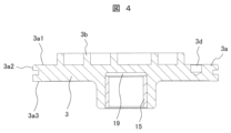
次に、前記背圧室18の油の一部を、給油ポケット3dを介して吸込部17に供給する部分の構成について、図1、図2を参照しつつ、図3~図5を用いて説明する。図3は図1に示す旋回スクロールの平面図、図4は図3のH-H線矢視断面図、図5は図2のJ-J線矢視断面図である。
Next, the configuration of the portion that supplies a portion of the oil in the
図3、図4において、3a1は旋回スクロール3の旋回鏡板3aの上面(旋回鏡板上面)で、旋回スクロール3が固定スクロール2に押し付けられる際のスラスト面(旋回スラスト面)となる。3a2は旋回鏡板3aの外周縁で、旋回鏡板縁とする。3a3は前記旋回鏡板3aの下面(旋回鏡板下面)で、この旋回鏡板下面3a3の下側に前記背圧室18が形成される。
In Figures 3 and 4, 3a1 is the upper surface (upper surface of the rotating mirror plate) of the
前記旋回鏡板上面3a1には渦巻状の旋回ラップ3bが立設されている。また、前記旋回鏡板上面3a1の外周側には、前記背圧室18の油が流入して油溜めとなる丸穴状の給油ポケット3dが形成されている。なお、図4に示す15は旋回軸受、19は前記クランク軸6のピン部6a上面と旋回スクロールとの間に形成される空間である旋回ボス部内空間(旋回軸受室)である。
A spiral-shaped
前記給油ポケット3dは、図2に示すように、旋回スクロール3の旋回運動に伴い、掃引領域31内で、32の矢印で示す旋回運動方向に軌跡を描いて、背圧室18(図1参照)と吸込室16に連通した吸込溝2rとに間欠的に連通するように構成されている。
As shown in FIG. 2, the
前記給油ポケット3dが背圧室18に連通している状態では、背圧室18内(圧力は吐出圧力と吸込圧力の中間の圧力)の油が前記給油ポケット3d内に溜められる。また、前記給油ポケット3dが、旋回スクロール3の旋回運動に伴い、前記吸込溝2r(圧力は吸込圧力)に連通すると、前記給油ポケット3d内の油が、圧力差により前記吸込溝2rを通って前記吸込室16に流入する。この動作を旋回スクロール3の旋回動作に伴って繰り返すことにより、前記背圧室18内の油は、順次吸込室16に移送される。前記給油ポケット3dの容積や個数を調整することにより、前記背圧室18から前記吸込室16への給油量を任意に調整することが可能となる。
When the
なお、図2、図3に示す例では、前記給油ポケット(給油凹部)3dを丸穴状(円形)に形成したが、これに限るものではなく、前記給油ポケット3dを深さの浅いスリット状(溝)としても良い。給油ポケット3dをスリット状とすることにより、背圧室と間欠的に連通させるだけでなく、背圧室18と吸込部17に常時連通させることも可能になる。給油ポケット3dに代えて、背圧室18と吸込溝2rを常時連通するスリット状の連通溝(給油凹部)とした場合でも、背圧室18と吸込部17との圧力差により、背圧室18の油を吸込室16側に流入させることができる。また、スリット状の連通溝の深さ、幅、長さ或いは個数などを調整することにより給油量を調整することもできる。
2 and 3, the oil supply pocket (oil supply recess) 3d is formed in a round hole (circular shape), but this is not limited thereto, and the
次に、給油ポケット3dを有する旋回スクロール3により、背圧室18の油を吸込部17に供給する給油経路の構成を、図2を参照しつつ、図5を用いて説明する。
旋回スクロール3の旋回に伴って、給油ポケット3dは、図2に示すように、所定の掃引領域31を矢印32で示す方向に旋回運動する。また、固定スクロール2には、前記給油ポケット3dの掃引領域31から吸込部17に向けて延在する吸込溝2rが設けられている。更に、前記固定スクロール2の固定ラップ2b外周側には、常時背圧室18(図1参照)と連通して油が保持されている環状凹部24と湾状凹部23が形成されている。前記湾状凹部23は、旋回スクロールに形成されている前記給油ポケット3dの旋回運動範囲(掃引領域)の一部と重なる位置に設けられている。
Next, the configuration of the oil supply path that supplies oil from the
As the
従って、前記給油ポケット3dは、前記吸込溝2rと前記湾状凹部23に対し、それぞれに重なる瞬間がある。給油ポケット3dを介して湾状凹部23と吸込溝2rは常時連通するわけではなく、旋回スクロール3の旋回動作に同期して、給油ポケット3dが湾状凹部23に臨んだときに油を汲み取り、給油ポケット3dが吸込溝2rへ臨んだときに吸込溝2rから吸込部17へ油を吐出する。
Therefore, there are moments when the
旋回スクロール3の一旋回当りの給油量は、給油ポケット3dの容積が上限となるため、過剰な油が吸込部17に供給されるのを抑制できる。このように、給油ポケット3dによって、背圧室18の油は、吸込部17へ少量だけ給油され、残りの油は圧縮室給油路28を介して圧縮室10へ供給される。
The amount of oil supplied per revolution of the
前記吸込溝2rの吸込部17側開口部は図2及び図5に示すように、逆流防止弁(壁部材)21の下部側(背面側)に開口し、逆流防止弁21が吸込溝2rから吐出する油の傘になる位置に設けられている。また、前記吸込溝2rの出口側はテーパ形状部2kに形成されており、図5に示すように、吸込溝2rから吸込部17に吐出する油は、水平方向だけでなく、上方側にも向かう流れが形成されるように構成されている。
As shown in Figures 2 and 5, the opening of the
即ち、前記テーパ形状部2kから吐出される油は、旋回ラップ3bの歯底側(固定ラップ2bの歯先側)だけでなく、旋回ラップ3bの歯先側(固定ラップ2bの歯底側)にも十分に供給されるように構成されている。
In other words, the oil discharged from the tapered
しかし、前記吸込溝2rの出口側をテーパ形状部2kに形成するだけでは、上方側に向かって油が吐出されても、吸込パイプ12から吸入される冷媒の流れ(流入ガスの流れG)によって、下方に押し付けられてしまい、旋回ラップ3bの歯先側(固定ラップ2bの歯底側)に油が十分に供給されないという課題を見い出した。そこで、本実施例では、前記吸込溝2rの出口側をテーパ形状部2kに形成すると共に、吸込溝2rの吸込部17側開口部を逆流防止弁21の下部側に開口させて、逆流防止弁21が吸込溝2rから流出する油の傘になるように構成したものである。
However, we found that simply forming the outlet side of the
本実施例のように構成することにより、前記テーパ形状部2kから吐出される油は吸込パイプ12からの流入ガスにより下方に押さえ付けられるのを抑制することができる。従って、テーパ形状部2kから吐出される油を、旋回ラップ3bの歯先側(固定ラップ2bの歯底側)にも十分に供給することができる。従って、吸込室16や圧縮室10におけるの潤滑を良好にすると共に、シール性も向上できるため、圧縮途中の作動流体の漏れも抑制できるから、スクロール圧縮機の効率を向上できる効果が得られる。
By configuring as in this embodiment, the oil discharged from the tapered
なお、前記テーパ形状部2kの開口端の位置は、本実施例では、前記逆流防止弁21の中心付近の下部に開口させている。即ち、前記テーパ形状部2kから吐出される油の上方側に向かう流れが、吸込口2sから流入するガス流れに対し、逆流防止弁21が傘として十分機能して、油が旋回ラップ3bの歯先側(固定ラップ2bの歯底側)にも十分供給されるように、前記テーパ形状部2kの開口端の位置を決める。例えば、逆流防止弁21の直径の40~60%の長さの部分が、テーパ形状部2kから吐出される油の傘として機能するように構成すると良い。
In this embodiment, the opening end of the tapered
また、旋回スクロール3の給油ポケット3dの径方向位置は、固定スクロール2に設けた吸込口2sの径方向位置と略同じ位置にすると、図2に示すように、吸込溝2rを固定ラップ2bに沿って円弧状に形成できるから製作が容易で、よりコンパクトに製作できる。
In addition, if the radial position of the
なお、前記吸込溝2rの出口側をテーパ形状部2kに形成したが、テーパ形状部2kの代わりに、1段または複数段の細かい段差でテーパ状に形成しても良い。このようにテーパ形状部2kを1段または複数段の段差で構成した段差形状部とすることにより、吐出される油の流れを乱流にして、拡散作用を助長することができる。
The outlet side of the
なお、本実施例では、逆流防止弁21を有する場合について説明したが、逆流防止弁を設けない場合には、前記テーパ形状部2kから吐出される油の傘となる壁部材を設けることにより同様の効果を得ることができる。この壁部材は、逆流防止弁21と同様に、吸込パイプ12から流入するガスの流れを、吸込口2sから吸込部17側に向かう斜め流れにするように設けると良い。
In this embodiment, the case where the
次に、図1に示す圧縮室給油路28の部分の構成について、図1、図2を参照しつつ、図6を用いて詳細に説明する。図6は図1のS部で囲む背圧弁27付近の部分拡大縦断面図である。
まず、前記背圧室18の機能について説明する。背圧室18は、固定スクロール2、旋回スクロール3及びフレーム4により囲まれた空間として形成され、この背圧室18には前述したように油が溜まっている。
Next, the configuration of the compression chamber
First, a description will be given of the function of the
スクロール圧縮機1では、その圧縮作用により、固定スクロール2と旋回スクロール3を互いに引離そうとする軸方向の力(引き離し力)が発生する。この軸方向の力により、前記両スクロールが引き離される、いわゆる旋回スクロール3の離脱現象が発生すると、圧縮室10の密閉性が悪化し、圧縮機効率を低下させる。
In the
そこで、旋回スクロール3の旋回鏡板3a背面側に、吐出圧力と吸込圧力の間の圧力となる背圧室18を設け、この背圧室18の圧力(背圧)により、前記引き離し力を打ち消すと共に、旋回スクロール3を固定スクロール2に押付けるようにしている。このときの押付力が大きすぎると、旋回スクロール3の旋回鏡板上面3a1(図4参照)と固定スクロール2の固定鏡板面2uとの摺動損失が増大し、圧縮機効率が低下する。
Therefore, a
つまり、前記背圧には最適な値が存在し、小さすぎると圧縮室の密閉性が悪化して熱流体損失が増大し、大きすぎると摺動損失が増大する。従って、背圧を最適な値に維持することが、圧縮機の高性能化、高信頼性化において重要である。 In other words, there is an optimal value for the back pressure; if it is too low, the compression chamber will not be tightly sealed, increasing thermal fluid loss, while if it is too high, friction loss will increase. Therefore, maintaining the back pressure at an optimal value is important for improving the performance and reliability of the compressor.
この最適な背圧値を得るため、本実施例のスクロール圧縮機では、図1に示すように、前記背圧室18の背圧を調整するための背圧弁27を有する前記圧縮室給油路28が前記固定スクロール2の支持部2cに備えられている。背圧室18の油は、背圧弁27が開くと、圧縮室給油路28を通じて圧縮室10に流入する。
To obtain this optimal back pressure value, in the scroll compressor of this embodiment, as shown in FIG. 1, the compression chamber
27aは、背圧弁27の弁座となる背圧弁ピース(弁座部品)で、固定スクロール2に圧入されている。29は背圧弁27とこの背圧弁を押圧するばね29bを収容する背圧弁収容空間であり、前記ばね29bはストッパ29aで支持されている。なお、図6に示す29cは止め栓であり、背圧弁流出路28bを設けるために形成された横穴の端部を密閉して塞ぐためのものである。
27a is a back pressure valve piece (valve seat part) that serves as the valve seat of the
圧縮室給油路28は、背圧室18に開口された背圧弁流入路28a、圧縮室10に連通された背圧弁流出路28b及び前記背圧弁27を収容している背圧弁収容空間29により構成されている。また、前記背圧弁流入路28aは、前記背圧弁ピース27aを貫通する穴で構成されている。
The compression chamber
ここで、図2により、本実施例における固定スクロール2の構成を説明する。
前記背圧弁流入路28a近傍の固定スクロール2には、固定鏡板面2uの内周側に位置する環状凹部24と、旋回鏡板3aの外周縁に位置する湾状凹部23が形成されている。前記環状凹部24は、旋回スクロール3の旋回鏡板3aが旋回運動するときの掃引範囲よりも大きい外径を有する環状、好ましくは円環状の部分として形成されている。
Here, the configuration of the fixed
In the fixed
前記湾状凹部23は、環状凹部24より内周側に位置し、固定ラップ2bの最外周部分に凹状、好ましくは湾状に食い込んだ形状に構成されている。この湾状凹部23は、常に旋回鏡板3aの外側まで広がっているため、背圧室18と常に連通しており、常に背圧室18の油が保持されている。これにより、圧縮室給油路28は、背圧室18の油を、湾状凹部23側の開口部から圧縮室10側に供給できる。
The bay-shaped
前記背圧弁27は、前記背圧弁流入路28aと前記背圧弁流出路28bを仕切るように配置されており、背圧室18の圧力(背圧)が所定値Pm以上になると開弁して、背圧は吐出圧Pdより低く維持される。これにより、背圧は、吸込圧力Psより高く吐出圧力Pdよりも低い圧力である中間圧力Pmになっている。また、圧縮室10による圧縮が開始され、背圧弁27が開くと、背圧室18の油が圧縮室10側に流入する。
The
つまり、前記背圧弁27は、背圧室18内の圧力がある値よりも高くなった場合に、該背圧室18内の流体を前記圧縮室10に逃がし、前記背圧室18の背圧を適正値に調整する機能を有している。
In other words, the
また、前記圧縮室10へ流入した油は、ラップ摺動面やラップ先端すき間などを良好に潤滑すると共に、圧縮室間などのシールに利用されて、シール性も向上できるため、スクロール圧縮機の効率を向上できる。
The oil that flows into the
圧縮室10に流入した油は、その後吐出口2dから吐出空間11に吐出される。この吐出された油の一部は、例えば、冷媒ガスと共に前記吐出パイプ13から冷凍サイクルへ吐出され、残りは密閉容器8内で冷媒ガスと分離されて密閉容器8底部の貯油部8dに貯溜される。
The oil that flows into the
なお、本実施例においては、背圧弁流出路28bは、吸込過程を完了して圧縮を開始した後の圧縮室10に連通している。また、前記背圧弁流出路28bの開口部は、図2に示すように、固定スクロール2の歯底中央に設けられ、旋回スクロールの旋回運動により旋回外線室と旋回内線室の両方に交互に連通するようにしている。従って、両方の圧縮室に油を供給することができ、何れかの圧縮室10で給油不足となる不具合も回避できる。
In this embodiment, the back pressure
上述したように、本発明の実施例1によれば、背圧室18へ流入した油は、図5に示す給油ポケット3dにより、吸込室16側に供給する第1の給油路と、圧縮室給油路28を経由して圧縮室10へ供給する第2の給油路を備えているので、吸込室16及び圧縮室10の潤滑及びシールを良好に行うことができる。従って、スクロール圧縮機の潤滑性を向上してスクロール圧縮機の信頼性を向上できると共に、体積効率を向上できるから、スクロール圧縮機の効率向上も図ることができる効果が得られる。
As described above, according to the first embodiment of the present invention, the oil flowing into the
また、本実施例では、前記背圧弁27を有する第2の給油路を設けているので、背圧室18内の油の一部を、吸込室16を経由することなく、前記背圧弁27を介して圧縮室10に直接供給することができる。
即ち、前記背圧室18へ供給された油のうち第1の給油路により決定される量だけが吸込室に導入され、残りの油は第2の給油路を介して圧縮室10に導入される。
従って、前記第1の給油路と第2の給油路のそれぞれの給油量を調整することにより、吸込室16への給油量と圧縮室10への給油量をそれぞれ適切な量に制御することが可能となる。
In addition, in this embodiment, a second oil supply passage having the
That is, of the oil supplied to the
Therefore, by adjusting the amount of oil supplied to each of the first oil supply passage and the second oil supply passage, it is possible to control the amount of oil supplied to the
本発明のスクロール圧縮機の実施例2を、図7を用いて説明する。図7は本実施例2を説明する図で、図5に相当する図である。なお、図7において、図1~図6と同じ符号を付した部分は同様の部分を示しており、同様の部分の説明は基本的に省略し、異なる部分を中心に説明する。 A second embodiment of the scroll compressor of the present invention will be described with reference to FIG. 7. FIG. 7 is a diagram for explaining this second embodiment, and corresponds to FIG. 5. In FIG. 7, parts with the same reference numerals as in FIG. 1 to FIG. 6 indicate similar parts, and explanations of similar parts will basically be omitted, with the focus on different parts being explained.
本実施例2でも、実施例1と同様に、旋回スクロール3に給油ポケット3dが設けられ、この給油ポケット3dには背圧室18の油が間歇的に供給されている。本実施例2が実施例1と異なる点は、前記給油ポケット3dに供給された油を、逆流防止弁(壁部材)21の上方(上流側)における吸込口2sの部分に吐出する給油経路2mを備えている点である。
In this second embodiment, as in the first embodiment, an
本実施例によれば、前記給油経路2mを備えることにより、給油ポケット3dに供給された油を、前記給油経路2mを介して、吸込パイプ12下方の吸込口2sに油を吐出することができる。従って、給油経路2mから吸込口2sに吐出された油は、吸込パイプ12から吸い込まれた流入ガスと共に、固定スクロール2の傾斜部2tに沿って吸込部17へ流れるので、油を旋回ラップ3bの歯先側(固定ラップ2bの歯底側)にも十分供給できる。
According to this embodiment, by providing the
また、本実施例2では、実施例1と同様に吸込溝2rとテーパ形状部2kも備えているから、給油ポケット3dの油を前記テーパ形状部2kから上方に向かって吐出する構成も有する。従って、実施例1と同様に、テーパ形状部2kから吐出される油についても旋回ラップ3bの歯先側(固定ラップ2bの歯底側)に供給することができる。
In addition, in this
従って、本実施例2によれば、実施例1と同様の効果が得られると共に、吸込室16や圧縮室10におけるの潤滑やシール性を更に良好にできるから、スクロール圧縮機の効率を更に向上できる。
Therefore, according to this
なお、図7に示す実施例2では、前記給油経路2mと、吸込溝2rとテーパ形状部2kを備える構成としているが、吸込溝2r下流のテーパ形状部2kを無くして吸込溝2rをその分延長する構成にしたり、或いは吸込溝2rも無くして、給油経路2mだけにしても、実施例1とほぼ同様の効果を得ることができる。
In the second embodiment shown in FIG. 7, the
本変形例2によれば、給油ポケット3dから供給された油を、逆流防止弁21の上方(上流側)における吸込口2sの部分に吐出するように構成しているので、旋回ラップ3bの歯先側(固定ラップ2bの歯底側)にも油を十分に供給することができ、吸込室16や圧縮室10におけるの潤滑やシール性を良好にできる。
According to this second modification, the oil supplied from the
本発明の実施例3を、図8を用いて説明する。図8は本発明のスクロール圧縮機を用いたヒートポンプ式給湯機を示すシステム概略図である。
ヒートポンプ式給湯機は、湯の沸き上げを行うヒートポンプユニット部40と、湯を溜める貯湯タンクユニット部41で構成されている。
A third embodiment of the present invention will be described with reference to Fig. 8. Fig. 8 is a system schematic diagram showing a heat pump water heater using the scroll compressor of the present invention.
The heat pump water heater is composed of a
ヒートポンプユニット部40は、容量可変可能なスクロール圧縮機1と、スクロール圧縮機1から吐出された高温高圧冷媒と被加熱媒体である水とを熱交換させる水-冷媒熱交換器(凝縮器)42と、水-冷媒熱交換器42から流出した冷媒を低温低圧に膨張させる膨張弁やキャピラリチューブなどの膨張手段43と、膨張手段43から流出した低温低圧冷媒と送風ファン44によって送風される空気とを熱交換させて冷媒を蒸発させる空気側熱交換器(蒸発器)45とを備える。空気側熱交換器45から流出した冷媒ガスはスクロール圧縮機1へ吸入される。これらの機器は環状に接続されて冷凍サイクル(加熱サイクル)を構成している。
The
また、スクロール圧縮機1の吐出部側の温度を検出する吐出冷媒温度検出部46、空気側熱交換器45から流出した冷媒の温度を検出する出口冷媒温度検出部47および外気温度を検出する外気温度検出部48を備える。前記各温度検出部46~48は制御部49に接続され、この制御部49は前記各温度検出部46~48で検出された温度に基づいて前記スクロール圧縮機1の容量や前記膨張手段43を制御する。なお、このヒートポンプ式給湯機における冷凍サイクルでは、冷媒として二酸化炭素が使用されている。
The
また,図8に示すように,水-冷媒熱交換器42には、貯湯タンク50の下部から低温の水が循環ポンプ51を駆動させることによって水配管52を介して供給され、水-冷媒熱交換器42で熱交換を行い、高温の湯になった後、貯湯タンク50上部に戻される。
一方、貯湯タンク50には、外部からの給水が該貯湯タンク50の下部から流入し、高温の湯が前記貯湯タンク50の上部から給湯され、台所や風呂などの用途に送られる。
As shown in FIG. 8 , low-temperature water is supplied to the water-
Meanwhile, water is supplied from the outside to the bottom of the hot
このように構成された本実施例3のヒートポンプ式給湯機は、前記スクロール圧縮機1として、上述した実施例1または実施例2に記載のスクロール圧縮機1を採用しているので、ヒートポンプ式給湯機の効率向上を図ることができる効果が得られる。
The heat pump water heater of this
なお、本発明は上述した実施例に限定されるものではなく、様々な変形例が含まれる。例えば、上記実施例では、スクロール圧縮機1として縦型のスクロール圧縮機としている場合について説明したが、横型のスクロール圧縮機にも同様に適用することが可能である。
また、上記した実施例は本発明を分かり易く説明するために詳細に説明したものであり、必ずしも説明した全ての構成を備えるものに限定されるものではない。
The present invention is not limited to the above-described embodiment, but includes various modified examples. For example, in the above embodiment, the
Furthermore, the above-described embodiment has been described in detail in order to easily explain the present invention, and the present invention is not necessarily limited to having all of the configurations described.
1…スクロール圧縮機、1A…圧縮機構部、
2…固定スクロール、2a…固定鏡板、2b…固定ラップ、2c…支持部、
2d…吐出口、2e…バイパス孔、2k…テーパ形状部、2m…給油経路、
2r…吸込溝、2s…吸込口、2t…傾斜部、
2u…固定鏡板面(スラスト支持面)、
3…旋回スクロール、3a…旋回鏡板、
3a1…旋回鏡板上面(旋回スラスト面)、3a2…旋回鏡板縁、
3a3…旋回鏡板下面、3b…旋回ラップ、3c…旋回ボス部、
3d…給油ポケット(給油凹部)、
4…フレーム、5…オルダムリング、
6…クランク軸、6a…偏心ピン部(ピン部)、6b…給油穴、6c…給油パイプ、
7…モータ部、7a…ロータ、7b…ステータ、
8…密閉容器、8a…胴部、8b…蓋キャップ、8c…底キャップ、8d…貯油部、
9…モータ室、10…圧縮室、11…吐出空間(固定背面室)、
12…吸込パイプ、13…吐出パイプ、14…主軸受、15…旋回軸受、
16…吸込室、17…吸込部、18…背圧室、
19…旋回ボス部内空間(旋回軸受室)、
21…逆流防止弁(壁部材)、22…バイパス弁、
23…湾状凹部、24…環状凹部、
25…副軸受、25a…軸受ブッシュ、25b…副軸受ハウジング、
26…副フレーム、27…背圧弁、27a…背圧弁ピース(弁座部品)、
28…圧縮室給油路、28a…背圧弁流入路、28b…背圧弁流出路、
29…背圧弁収容空間、29a…ストッパ、29b…ばね、29c…止め栓、
30…電源端子、31…旋回運動するときの掃引領域、32…旋回運動方向、
35,36…カウンタウエイト、37…ストッパ、38…ばね、
40…ヒートポンプユニット部、41…貯湯タンクユニット部、
42…水-冷媒熱交換器(凝縮器)、43…膨張手段、44…送風ファン、
45…空気側熱交換器(蒸発器)、46…吐出冷媒温度検出部、
47…出口冷媒温度検出部、48…外気温度検出部、49…制御部、
50…貯湯タンク、51…循環ポンプ、52…水配管。
1...Scroll compressor, 1A...Compression mechanism part,
2... fixed scroll, 2a... fixed end plate, 2b... fixed wrap, 2c... support portion,
2d: discharge port; 2e: bypass hole; 2k: tapered portion; 2m: oil supply path;
2r...suction groove, 2s...suction port, 2t...inclined portion,
2u: fixed end plate surface (thrust support surface),
3...rotating scroll, 3a...rotating head plate,
3a1: upper surface of the rotating head (rotating thrust surface), 3a2: edge of the rotating head,
3a3...lower surface of the rotating head plate, 3b...rotating wrap, 3c...rotating boss portion,
3d...oil supply pocket (oil supply recess),
4...Frame, 5...Oldham Ring,
6... crankshaft, 6a... eccentric pin portion (pin portion), 6b... oil supply hole, 6c... oil supply pipe,
7...motor section, 7a...rotor, 7b...stator,
8: sealed container, 8a: body, 8b: lid cap, 8c: bottom cap, 8d: oil storage section,
9: motor chamber, 10: compression chamber, 11: discharge space (fixed rear chamber),
12...suction pipe, 13...discharge pipe, 14...main bearing, 15...slewing bearing,
16...suction chamber, 17...suction section, 18...back pressure chamber,
19...Space inside the swivel boss (swivel bearing chamber),
21: check valve (wall member), 22: bypass valve,
23... bay-shaped recess, 24... annular recess,
25... Auxiliary bearing, 25a... Bearing bush, 25b... Auxiliary bearing housing,
26... sub-frame, 27... back pressure valve, 27a... back pressure valve piece (valve seat part),
28... compression chamber oil supply passage, 28a... back pressure valve inlet passage, 28b... back pressure valve outlet passage,
29: Back pressure valve accommodating space; 29a: Stopper; 29b: Spring; 29c: Stopper plug;
30: power supply terminal; 31: sweep area during pivoting; 32: pivoting direction;
35, 36 ... counterweight, 37 ... stopper, 38 ... spring,
40... heat pump unit section, 41... hot water tank unit section,
42...water-refrigerant heat exchanger (condenser), 43...expansion means, 44...blower fan,
45: air-side heat exchanger (evaporator), 46: discharge refrigerant temperature detection unit,
47: Outlet refrigerant temperature detection unit, 48: Outside air temperature detection unit, 49: Control unit,
50...hot water tank, 51...circulation pump, 52...water piping.
Claims (12)
前記吸込口と前記吸込室との間の前記固定鏡板に設けられた吸込部と、
前記吸込口における前記吸込パイプとは反対側に設けられ、吸込パイプからの冷媒ガスの流れを斜め流れに偏向させる壁部材と、
前記旋回鏡板の外周側に設けられ、前記背圧室の油が導かれる給油凹部と、
前記固定鏡板に設けられ、前記給油凹部の油を前記吸込部側に導く吸込溝と、
前記吸込溝の出口側に形成され、前記吸込溝からの油の少なくとも一部を前記旋回ラップの歯先側に吐出させるためのテーパ形状部と、を備え、
前記吸込溝の吸込部側開口部を前記壁部材の背面側に開口させ、前記壁部材が、前記吸込パイプから流入する冷媒ガスに対し、前記吸込溝から流出する油の傘となるように構成していることを特徴とするスクロール圧縮機。 a crankshaft for causing the orbiting scroll to perform orbital motion; an orbiting bearing provided in an orbiting boss portion of the orbiting scroll for supporting the orbiting scroll axially and rotatably relative to an eccentric pin portion of the crankshaft; an orbiting boss inner space having a pressure close to a discharge pressure to which lubricating oil stored in a sealed container is introduced; a back pressure chamber provided on the back surface of the orbiting scroll and radially outward of the orbiting boss inner space, the back pressure chamber being a pressure between the discharge pressure and the suction pressure; and a suction port provided on the radially outward side of the fixed end plate of the fixed scroll to which a refrigerant gas from a suction pipe is introduced.
A suction portion provided on the fixed end plate between the suction port and the suction chamber;
a wall member provided on an opposite side of the suction pipe at the suction port, the wall member deflecting a flow of the refrigerant gas from the suction pipe into an oblique flow;
an oil supply recess provided on an outer circumferential side of the rotating head, into which oil from the back pressure chamber is guided;
a suction groove provided in the fixed end plate for guiding oil from the oil supply recess toward the suction portion;
a tapered portion formed on an outlet side of the suction groove for discharging at least a portion of the oil from the suction groove to a tooth tip side of the orbiting wrap,
a suction groove having an opening on the suction portion side that opens onto a rear surface side of the wall member, and the wall member is configured to act as an umbrella for oil flowing out of the suction groove against refrigerant gas flowing in from the suction pipe.
前記吸込部を形成している前記固定鏡板に設けられ、前記吸込口側から前記吸込室側に向かって傾斜する傾斜部を備え、
前記壁部材は、吸込パイプからの冷媒ガスの流れを前記傾斜部側に偏向させることを特徴とするスクロール圧縮機。 The scroll compressor according to claim 1,
The fixed end plate forming the suction portion includes an inclined portion inclined from the suction port side toward the suction chamber side,
The scroll compressor, wherein the wall member deflects a flow of refrigerant gas from a suction pipe toward the inclined portion.
前記吸込溝から吐出される油の少なくとも一部は前記傾斜部側に吐出されるように前記テーパ形状部が形成されていることを特徴とするスクロール圧縮機。 The scroll compressor according to claim 2,
The scroll compressor, wherein the tapered portion is formed so that at least a portion of the oil discharged from the suction groove is discharged toward the inclined portion.
前記給油凹部は、前記旋回スクロールの旋回鏡板上面の外周側に形成された給油ポケットであることを特徴とするスクロール圧縮機。 The scroll compressor according to claim 1,
The scroll compressor according to claim 1, wherein the oil supply recess is an oil supply pocket formed on an outer circumferential side of an upper surface of a rotating head plate of the rotating scroll.
前記壁部材は、前記吸込口に設けられた逆流防止弁であることを特徴とするスクロール圧縮機。 The scroll compressor according to claim 1,
The scroll compressor according to claim 1, wherein the wall member is a check valve provided at the suction port .
前記吸込溝の吸込部側開口部を前記逆流防止弁の背面側に開口させ、前記逆流防止弁が、前記吸込パイプから流入する冷媒ガスに対し、前記吸込溝から流出する油の傘となるように構成されていることを特徴とするスクロール圧縮機。 The scroll compressor according to claim 5,
a check valve configured to act as an umbrella of oil flowing out of the suction groove against refrigerant gas flowing in from the suction pipe, the check valve being configured so that an opening of the suction groove on the suction portion side opens to a rear side of the check valve, the check valve acting as an umbrella of oil flowing out of the suction groove against refrigerant gas flowing in from the suction pipe.
前記吸込溝における前記テーパ形状部の開口端の位置は、前記逆流防止弁の背面側であって、逆流防止弁の直径の40~60%の長さの部分が、前記テーパ形状部から吐出される油の傘として機能することを特徴とするスクロール圧縮機。 The scroll compressor according to claim 6,
A scroll compressor characterized in that an opening end of the tapered portion in the suction groove is located on the back side of the check valve, and a portion having a length of 40 to 60% of the diameter of the check valve functions as an umbrella for oil discharged from the tapered portion.
前記吸込溝における前記テーパ形状部の開口端の位置は、前記逆流防止弁の中心付近の背面側に形成されていることを特徴とするスクロール圧縮機。 The scroll compressor according to claim 7,
a tapered portion of the suction groove having an opening end located on a rear surface side of the check valve near a center thereof;
前記固定スクロールには、前記背圧室の背圧を調整するための背圧弁を有する圧縮室給油路が備えられ、この圧縮室給油路は、前記背圧室に開口される背圧弁流入路と、前記圧縮室に連通する背圧弁流出路を備えることを特徴とするスクロール圧縮機。 The scroll compressor according to claim 1,
the fixed scroll is provided with a compression chamber oil supply passage having a back pressure valve for adjusting the back pressure of the back pressure chamber, the compression chamber oil supply passage including a back pressure valve inlet passage opening into the back pressure chamber and a back pressure valve outlet passage communicating with the compression chamber.
前記吸込口と前記吸込室との間の前記固定鏡板に設けられた吸込部と、
前記吸込口における前記吸込パイプとは反対側に設けられ、吸込パイプからの冷媒ガスの流れを斜め流れに偏向させる壁部材と、
前記旋回鏡板の外周側に設けられ、前記背圧室の油が導かれる給油凹部と、
前記固定鏡板に設けられ、前記給油凹部の油を前記壁部材の上流側における前記吸込口に吐出する給油経路を設けていることを特徴とするスクロール圧縮機。 a crankshaft for causing the orbiting scroll to perform orbital motion; an orbiting bearing provided in an orbiting boss portion of the orbiting scroll for supporting the orbiting scroll axially and rotatably relative to an eccentric pin portion of the crankshaft; an orbiting boss inner space having a pressure close to a discharge pressure to which lubricating oil stored in a sealed container is introduced; a back pressure chamber provided on the back surface of the orbiting scroll and radially outward of the orbiting boss inner space, the back pressure chamber being a pressure between the discharge pressure and the suction pressure; and a suction port provided on the radially outward side of the fixed end plate of the fixed scroll to which a refrigerant gas from a suction pipe is introduced.
A suction portion provided on the fixed end plate between the suction port and the suction chamber;
a wall member provided on an opposite side of the suction pipe at the suction port, the wall member deflecting a flow of the refrigerant gas from the suction pipe into an oblique flow;
an oil supply recess provided on an outer circumferential side of the rotating head, into which oil from the back pressure chamber is guided;
a fixed end plate having an oil supply passage for discharging oil from the oil supply recess to the suction port on the upstream side of the wall member;
前記固定鏡板に設けられ、前記給油凹部の油を前記吸込部側に導く吸込溝と、
前記吸込溝の出口側に形成され、前記吸込溝からの油の少なくとも一部を前記旋回ラップの歯先側に吐出させるためのテーパ形状部を更に備え、
前記吸込溝の吸込部側開口部を前記壁部材の背面側に開口させ、前記壁部材が、前記吸込パイプから流入する冷媒ガスに対し、前記吸込溝から流出する油の傘となるように構成していることを特徴とするスクロール圧縮機。 The scroll compressor according to claim 10,
a suction groove provided in the fixed end plate for guiding oil from the oil supply recess toward the suction portion;
A tapered portion is formed on an outlet side of the suction groove for discharging at least a portion of the oil from the suction groove to a tooth tip side of the orbiting wrap,
a suction groove having an opening on the suction portion side that opens onto a rear surface side of the wall member, and the wall member is configured to act as an umbrella for oil flowing out of the suction groove against refrigerant gas flowing in from the suction pipe.
Priority Applications (1)
| Application Number | Priority Date | Filing Date | Title |
|---|---|---|---|
| JP2022094219A JP7619981B2 (en) | 2022-06-10 | 2022-06-10 | Scroll compressor and heat pump water heater |
Applications Claiming Priority (1)
| Application Number | Priority Date | Filing Date | Title |
|---|---|---|---|
| JP2022094219A JP7619981B2 (en) | 2022-06-10 | 2022-06-10 | Scroll compressor and heat pump water heater |
Publications (2)
| Publication Number | Publication Date |
|---|---|
| JP2023180698A JP2023180698A (en) | 2023-12-21 |
| JP7619981B2 true JP7619981B2 (en) | 2025-01-22 |
Family
ID=89306874
Family Applications (1)
| Application Number | Title | Priority Date | Filing Date |
|---|---|---|---|
| JP2022094219A Active JP7619981B2 (en) | 2022-06-10 | 2022-06-10 | Scroll compressor and heat pump water heater |
Country Status (1)
| Country | Link |
|---|---|
| JP (1) | JP7619981B2 (en) |
Citations (6)
| Publication number | Priority date | Publication date | Assignee | Title |
|---|---|---|---|---|
| JP2011052590A (en) | 2009-09-02 | 2011-03-17 | Hitachi Appliances Inc | Scroll compressor, refrigeration cycle device, and heat pump water heater |
| JP2014080873A (en) | 2012-10-15 | 2014-05-08 | Hitachi Appliances Inc | Scroll compressor |
| JP2014206060A (en) | 2013-04-11 | 2014-10-30 | 日立アプライアンス株式会社 | Scroll compressor |
| WO2014196314A1 (en) | 2013-06-03 | 2014-12-11 | 日立アプライアンス株式会社 | Scroll compressor and air conditioner using same |
| JP2017053279A (en) | 2015-09-10 | 2017-03-16 | ジョンソンコントロールズ ヒタチ エア コンディショニング テクノロジー(ホンコン)リミテッド | Scroll compressor |
| US20180231002A1 (en) | 2017-02-13 | 2018-08-16 | Lg Electronics Inc. | Scroll compressor |
Family Cites Families (2)
| Publication number | Priority date | Publication date | Assignee | Title |
|---|---|---|---|---|
| JPH06317271A (en) * | 1993-05-06 | 1994-11-15 | Hitachi Ltd | Hermetic scroll compressor |
| JP3584533B2 (en) * | 1995-04-12 | 2004-11-04 | 株式会社日立製作所 | Scroll compressor |
-
2022
- 2022-06-10 JP JP2022094219A patent/JP7619981B2/en active Active
Patent Citations (6)
| Publication number | Priority date | Publication date | Assignee | Title |
|---|---|---|---|---|
| JP2011052590A (en) | 2009-09-02 | 2011-03-17 | Hitachi Appliances Inc | Scroll compressor, refrigeration cycle device, and heat pump water heater |
| JP2014080873A (en) | 2012-10-15 | 2014-05-08 | Hitachi Appliances Inc | Scroll compressor |
| JP2014206060A (en) | 2013-04-11 | 2014-10-30 | 日立アプライアンス株式会社 | Scroll compressor |
| WO2014196314A1 (en) | 2013-06-03 | 2014-12-11 | 日立アプライアンス株式会社 | Scroll compressor and air conditioner using same |
| JP2017053279A (en) | 2015-09-10 | 2017-03-16 | ジョンソンコントロールズ ヒタチ エア コンディショニング テクノロジー(ホンコン)リミテッド | Scroll compressor |
| US20180231002A1 (en) | 2017-02-13 | 2018-08-16 | Lg Electronics Inc. | Scroll compressor |
Also Published As
| Publication number | Publication date |
|---|---|
| JP2023180698A (en) | 2023-12-21 |
Similar Documents
| Publication | Publication Date | Title |
|---|---|---|
| CN101165350B (en) | scroll compressor | |
| JP6302813B2 (en) | Scroll compressor and refrigeration cycle apparatus using the same | |
| US8316664B2 (en) | Refrigeration cycle apparatus and fluid machine used therefor | |
| CN109996962B (en) | Asymmetric scroll compressor | |
| JP2012207655A (en) | Rankine cycle apparatus | |
| JP2011038480A (en) | Scroll fluid machine | |
| CN114026328B (en) | Scroll compressor and air conditioner using the scroll compressor | |
| JP4337820B2 (en) | Scroll type fluid machinery | |
| CN104105881B (en) | scroll compressor | |
| EP3594502B1 (en) | Scroll compressor | |
| JP7619981B2 (en) | Scroll compressor and heat pump water heater | |
| JP6143862B2 (en) | Scroll compressor and air conditioner using the same | |
| JP6061044B2 (en) | Scroll compressor | |
| JP7481640B2 (en) | Scroll compressor and refrigeration device | |
| JP7606947B2 (en) | Scroll compressor and refrigeration cycle device using the same | |
| WO2013160953A1 (en) | Expansion device with integrated compression mechanism | |
| JP7702647B2 (en) | Scroll Compressor | |
| JP7161139B1 (en) | Scroll compressor and refrigeration cycle device | |
| JP2011163256A (en) | Scroll compressor | |
| WO2022185956A1 (en) | Compressor and refrigeration cycle device | |
| JP2024112223A (en) | Compressor | |
| JP2014101804A (en) | Scroll type compressor | |
| JP2014009647A (en) | Compressor | |
| JP2007032293A (en) | Scroll compressor | |
| JP2015078665A (en) | Scroll compressor |
Legal Events
| Date | Code | Title | Description |
|---|---|---|---|
| A621 | Written request for application examination |
Free format text: JAPANESE INTERMEDIATE CODE: A621 Effective date: 20240325 |
|
| A977 | Report on retrieval |
Free format text: JAPANESE INTERMEDIATE CODE: A971007 Effective date: 20240912 |
|
| A131 | Notification of reasons for refusal |
Free format text: JAPANESE INTERMEDIATE CODE: A131 Effective date: 20240924 |
|
| A521 | Request for written amendment filed |
Free format text: JAPANESE INTERMEDIATE CODE: A523 Effective date: 20240927 |
|
| TRDD | Decision of grant or rejection written | ||
| A01 | Written decision to grant a patent or to grant a registration (utility model) |
Free format text: JAPANESE INTERMEDIATE CODE: A01 Effective date: 20241224 |
|
| A61 | First payment of annual fees (during grant procedure) |
Free format text: JAPANESE INTERMEDIATE CODE: A61 Effective date: 20250109 |
|
| R150 | Certificate of patent or registration of utility model |
Ref document number: 7619981 Country of ref document: JP Free format text: JAPANESE INTERMEDIATE CODE: R150 |