JP7619084B2 - Carbon Dioxide Capture System - Google Patents
Carbon Dioxide Capture System Download PDFInfo
- Publication number
- JP7619084B2 JP7619084B2 JP2021030389A JP2021030389A JP7619084B2 JP 7619084 B2 JP7619084 B2 JP 7619084B2 JP 2021030389 A JP2021030389 A JP 2021030389A JP 2021030389 A JP2021030389 A JP 2021030389A JP 7619084 B2 JP7619084 B2 JP 7619084B2
- Authority
- JP
- Japan
- Prior art keywords
- carbon dioxide
- liquid
- working electrode
- adsorption
- unit
- Prior art date
- Legal status (The legal status is an assumption and is not a legal conclusion. Google has not performed a legal analysis and makes no representation as to the accuracy of the status listed.)
- Active
Links
Images


Classifications
-
- B—PERFORMING OPERATIONS; TRANSPORTING
- B01—PHYSICAL OR CHEMICAL PROCESSES OR APPARATUS IN GENERAL
- B01D—SEPARATION
- B01D53/00—Separation of gases or vapours; Recovering vapours of volatile solvents from gases; Chemical or biological purification of waste gases, e.g. engine exhaust gases, smoke, fumes, flue gases, aerosols
- B01D53/02—Separation of gases or vapours; Recovering vapours of volatile solvents from gases; Chemical or biological purification of waste gases, e.g. engine exhaust gases, smoke, fumes, flue gases, aerosols by adsorption, e.g. preparative gas chromatography
- B01D53/04—Separation of gases or vapours; Recovering vapours of volatile solvents from gases; Chemical or biological purification of waste gases, e.g. engine exhaust gases, smoke, fumes, flue gases, aerosols by adsorption, e.g. preparative gas chromatography with stationary adsorbents
- B01D53/0407—Constructional details of adsorbing systems
-
- B—PERFORMING OPERATIONS; TRANSPORTING
- B01—PHYSICAL OR CHEMICAL PROCESSES OR APPARATUS IN GENERAL
- B01D—SEPARATION
- B01D53/00—Separation of gases or vapours; Recovering vapours of volatile solvents from gases; Chemical or biological purification of waste gases, e.g. engine exhaust gases, smoke, fumes, flue gases, aerosols
- B01D53/32—Separation of gases or vapours; Recovering vapours of volatile solvents from gases; Chemical or biological purification of waste gases, e.g. engine exhaust gases, smoke, fumes, flue gases, aerosols by electrical effects other than those provided for in group B01D61/00
- B01D53/326—Separation of gases or vapours; Recovering vapours of volatile solvents from gases; Chemical or biological purification of waste gases, e.g. engine exhaust gases, smoke, fumes, flue gases, aerosols by electrical effects other than those provided for in group B01D61/00 in electrochemical cells
-
- B—PERFORMING OPERATIONS; TRANSPORTING
- B01—PHYSICAL OR CHEMICAL PROCESSES OR APPARATUS IN GENERAL
- B01D—SEPARATION
- B01D2257/00—Components to be removed
- B01D2257/50—Carbon oxides
- B01D2257/504—Carbon dioxide
-
- Y—GENERAL TAGGING OF NEW TECHNOLOGICAL DEVELOPMENTS; GENERAL TAGGING OF CROSS-SECTIONAL TECHNOLOGIES SPANNING OVER SEVERAL SECTIONS OF THE IPC; TECHNICAL SUBJECTS COVERED BY FORMER USPC CROSS-REFERENCE ART COLLECTIONS [XRACs] AND DIGESTS
- Y02—TECHNOLOGIES OR APPLICATIONS FOR MITIGATION OR ADAPTATION AGAINST CLIMATE CHANGE
- Y02C—CAPTURE, STORAGE, SEQUESTRATION OR DISPOSAL OF GREENHOUSE GASES [GHG]
- Y02C20/00—Capture or disposal of greenhouse gases
- Y02C20/40—Capture or disposal of greenhouse gases of CO2
Landscapes
- Chemical & Material Sciences (AREA)
- Engineering & Computer Science (AREA)
- Analytical Chemistry (AREA)
- General Chemical & Material Sciences (AREA)
- Oil, Petroleum & Natural Gas (AREA)
- Chemical Kinetics & Catalysis (AREA)
- Electrochemistry (AREA)
- Treating Waste Gases (AREA)
- Carbon And Carbon Compounds (AREA)
- Electrolytic Production Of Non-Metals, Compounds, Apparatuses Therefor (AREA)
- Separation Of Gases By Adsorption (AREA)
- Gas Separation By Absorption (AREA)
Description
本発明は、二酸化炭素を含有する二酸化炭素含有ガスから二酸化炭素を回収する二酸化炭素回収システムに関する。 The present invention relates to a carbon dioxide capture system that captures carbon dioxide from a carbon dioxide-containing gas.
特許文献1では、電気化学反応によって二酸化炭素含有ガスから二酸化炭素を分離するガス分離システムが提案されている。特許文献1のガス分離システムでは、電気化学セルの作用極に二酸化炭素を吸着可能な二酸化炭素吸着材が設けられている。二酸化炭素吸着材は電気活性種であり、作用極と対極の間の電位差を変化させることで、二酸化炭素吸着材による二酸化炭素の吸着と放出を切り替えることができる。
しかしながら、上記特許文献1の構成では、二酸化炭素回収時に、作用極周りに存在する二酸化炭素以外のガス(例えば、窒素、酸素等)も一緒に回収される可能性がある。このため、回収される二酸化炭素の純度が低下するおそれがある。
However, in the configuration of
本発明は、上記点に鑑みて、回収される二酸化炭素の純度を向上させることができる二酸化炭素回収システムを提供することを目的とする。 In view of the above, the present invention aims to provide a carbon dioxide capture system that can improve the purity of the captured carbon dioxide.
上記目的を達成するため、請求項1に記載の二酸化炭素回収システムは、電気化学反応によって二酸化炭素を含有する二酸化炭素含有ガスから二酸化炭素を分離する二酸化炭素回収システムにおいて、
作用極(102)と対極(103)とを有するとともに、作用極と対極との間に電圧が印加されることで、対極から作用極に電子が供給され、作用極は電子が供給されることに伴って二酸化炭素と結合する電気化学セル(101)と、
電気化学セルが収容されるとともに、二酸化炭素含有ガスが導入される吸着部(100)と、
作用極と対極との間に電圧が印加された状態で、液体を吸着部内に供給する供給部(142、143)と、
作用極と対極との間に電圧が印加された状態で、供給部から供給された液体、および二酸化炭素含有ガスから二酸化炭素が分離された後の二酸化炭素除去ガスを吸着部から排出する排出部(1b、144、145)と、を備え、
作用極は、電極基材(102a)と、二酸化炭素吸着材(102b)と、を有しており、
作用極と対極との間に電圧が印加されることで、対極から作用極に電子が供給され、二酸化炭素吸着材は電子が供給されることに伴って二酸化炭素と結合しており、
二酸化炭素吸着材は、被覆材(102c)に覆われている。
In order to achieve the above object, the carbon dioxide recovery system according to
an electrochemical cell (101) having a working electrode (102) and a counter electrode (103), in which, when a voltage is applied between the working electrode and the counter electrode, electrons are supplied from the counter electrode to the working electrode, and the working electrode is combined with carbon dioxide as the electrons are supplied;
an adsorption section (100) in which an electrochemical cell is housed and into which a carbon dioxide-containing gas is introduced;
A supply unit (142, 143) that supplies a liquid into the adsorption unit while a voltage is applied between the working electrode and the counter electrode;
and an exhaust section (1b, 144, 145) that exhausts, from the adsorption section, the liquid supplied from the supply section and the carbon dioxide-removed gas obtained after carbon dioxide is separated from the carbon dioxide-containing gas, while a voltage is applied between the working electrode and the counter electrode ;
The working electrode has an electrode substrate (102a) and a carbon dioxide adsorbent (102b),
When a voltage is applied between the working electrode and the counter electrode, electrons are supplied from the counter electrode to the working electrode, and the carbon dioxide adsorbent bonds with carbon dioxide as the electrons are supplied.
The carbon dioxide adsorbent is covered with a covering material (102c) .
これによれば、供給部(142、143)および排出部(1b、144、145)を設けることで、吸着部(100)から液体とともに二酸化炭素除去ガスを排出することができる。その結果、吸着部(100)内の二酸化炭素の純度を高めることができるので、回収される二酸化炭素の純度を向上させることができる。 Accordingly, by providing the supply section (142, 143) and the discharge section (1b, 144, 145), the carbon dioxide-removed gas can be discharged together with the liquid from the adsorption section (100). As a result, the purity of the carbon dioxide in the adsorption section (100) can be increased, and the purity of the recovered carbon dioxide can be improved.
なお、この欄および特許請求の範囲で記載した各手段の括弧内の符号は、後述する実施形態に記載の具体的手段との対応関係を示すものである。 Note that the symbols in parentheses for each means described in this section and in the claims indicate the corresponding relationship with the specific means described in the embodiments described below.
以下、本発明の実施形態について図に基づいて説明する。なお、以下の各実施形態相互において、互いに同一もしくは均等である部分には、図中、同一符号を付してある。 Embodiments of the present invention will be described below with reference to the drawings. Note that in the following embodiments, parts that are the same or equivalent to each other are given the same reference numerals in the drawings.
(第1実施形態)
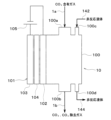
図1~図10を用いて、本発明を実施するための第1実施形態を説明する。図1に示すように、本実施形態の二酸化炭素回収システム1は、圧縮機11、二酸化炭素回収装置10、流路切替弁12、二酸化炭素利用装置13、液体回路14、制御装置15が設けられている。
First Embodiment
A first embodiment for carrying out the present invention will be described with reference to Figures 1 to 10. As shown in Figure 1, a carbon
圧縮機11は、二酸化炭素含有ガスを二酸化炭素回収装置10に圧送する。二酸化炭素含有ガスは、二酸化炭素と二酸化炭素以外のガスを含有する混合ガスであり、例えば大気や内燃機関の排気ガスを用いることができる。圧縮機11は、制御装置15から出力される制御電圧によって、回転数(すなわち、圧送能力)が制御される。
The
二酸化炭素回収装置10は、二酸化炭素含有ガスから二酸化炭素を分離して回収する装置である。二酸化炭素回収装置10は、二酸化炭素含有ガスから二酸化炭素が回収された後の二酸化炭素除去ガス、あるいは二酸化炭素含有ガスから回収した二酸化炭素を排出する。二酸化炭素回収装置10の構成については、後で詳細に説明する。
The carbon
流路切替弁12は、二酸化炭素回収装置10の排出ガスの流路を切り替える三方弁である。流路切替弁12は、二酸化炭素回収装置10から二酸化炭素除去ガスが排出される場合は、排出ガスの流路を大気側に切り替え、二酸化炭素回収装置10から二酸化炭素が排出される場合は、排出ガスの流路を二酸化炭素利用装置13側に切り替える。流路切替弁12は、制御装置15から出力される制御電圧によって、その作動が制御される。
The flow
二酸化炭素利用装置13は、二酸化炭素を利用する装置である。二酸化炭素利用装置13としては、例えば二酸化炭素を貯蔵する貯蔵タンクや二酸化炭素を燃料に変換する変換装置を用いることができる。変換装置は、二酸化炭素をメタン等の炭化水素燃料に変換する装置を用いることができる。炭化水素燃料は、常温常圧で気体の燃料であってもよく、常温常圧で液体の燃料であってもよい。
The carbon
液体回路14は、液体を二酸化炭素回収装置10に循環させる。以下、液体回路14を循環する液体を循環液体という。循環液体としては、二酸化炭素に対して非化学反応性および不溶性を有している液体を用いることができる。液体回路14の構成については、後で詳細に説明する。
The
制御装置15は、CPU、ROMおよびRAM等を含む周知のマイクロコンピュータとその周辺回路から構成されている。制御装置15は、ROM内に記憶された制御プログラムに基づいて各種演算、処理を行い、各種制御対象機器の作動を制御する。制御装置15は制御部の一例に相当する。
The
制御装置15の出力側には、各種制御対象機器が接続されている。各種制御対象機器には、圧縮機11、二酸化炭素回収装置10、流路切替弁12、液体回路14の構成機器(すなわち、後述する液体供給ポンプ143および液体排出ポンプ145)等が含まれる。
The output side of the
次に、二酸化炭素回収装置10について図2および図3を用いて説明する。図2に示すように、二酸化炭素回収装置10は、吸着部100と、電気化学セル101とを有している。吸着部100は、電気化学セル101が収容される容器である。吸着部100には、二酸化炭素含有ガスおよび循環液体が導入される。
Next, the carbon
吸着部100には、ガス流入口100a、ガス流出口100b、液体流入口100c、および液体流出口100dが設けられている。ガス流入口100aは、二酸化炭素含有ガスを吸着部100内に流入させる。ガス流出口100bは、二酸化炭素除去ガスや二酸化炭素を吸着部100内から流出させる。液体流入口100cは、循環液体を吸着部100内に流入させる。液体流出口100dは、循環液体を吸着部100から流出させる。
The
ガス流入口100aには、ガス供給流路1aが接続されている。ガス供給流路1aは、圧縮機11の吐出口側とガス流入口100aとを接続して、圧縮機11から吐出された二酸化炭素含有ガスを吸着部100に供給する。
A gas
ガス流出口100bには、ガス排出流路1bが接続されている。ガス排出流路1bは、ガス流出口100bと流路切替弁12の入口側とを接続して、吸着部100内から排出された二酸化炭素除去ガスや二酸化炭素を流路切替弁12の入口側へ導く。
The
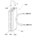
図3に示すように、電気化学セル101は、作用極102、対極103、絶縁層104を有している。図3に示す例では、作用極102、対極103、絶縁層104をそれぞれ板状に構成している。なお、図3では、作用極102、対極103、絶縁層104を、それぞれ間隔を設けて図示しているが、実際はこれらの構成要素は接するように配置されている。
As shown in FIG. 3, the
二酸化炭素回収装置10は、電気化学反応によって二酸化炭素の吸着および脱離を行い、二酸化炭素含有ガスから二酸化炭素を分離して回収する。二酸化炭素回収装置10は、作用極102と対極103に所定の電圧を印加する電圧印加部である電源105を有しており、作用極102と対極103の電位差を変化させることができる。作用極102は負極であり、対極103は正極である。
The carbon
電気化学セル101は、作用極102と対極103との間に電圧が印加されることで、対極103から作用極102に電子が供給され、作用極102(より詳細には、後述する二酸化炭素吸着材102b)は電子が供給されることに伴って二酸化炭素と結合する。
In the
電気化学セル101は、作用極102と対極103の電位差を変化させることで、作用極102に二酸化炭素を吸着させる二酸化炭素吸着モードと、作用極102から二酸化炭素を回収する二酸化炭素回収モードを切り替えて作動することができる。二酸化炭素吸着モードは電気化学セル101を充電する充電モードであり、二酸化炭素回収モードは電気化学セル101を放電する放電モードである。
The
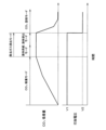
二酸化炭素吸着モードでは、作用極102と対極103の間に第1の電圧V1が印加され、対極103から作用極102に電子が供給される。第1の電圧V1では、作用極電位<対極電位となっている。第1の電圧V1は、例えば0.5~2.0Vの範囲内とすることができる。
In the carbon dioxide adsorption mode, a first voltage V1 is applied between the working
二酸化炭素回収モードでは、作用極102と対極103の間に低い第2の電圧V2が印加され、作用極102から対極103に電子が供給される。第2の電圧V2は、第1の電圧V1より低い電圧であればよく、作用極電位と対極電位の大小関係は限定されない。つまり、二酸化炭素回収モードでは、作用極電位<対極電位でもよく、作用極電位=対極電位でもよく、作用極電位>対極電位でもよい。
In the carbon dioxide capture mode, a low second voltage V2 is applied between the working
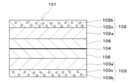
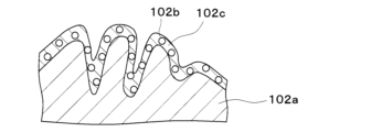
図4に示すように、作用極102には、作用極側基材102aと二酸化炭素吸着材102bが設けられている。図4では便宜上、二酸化炭素吸着材102bが作用極側基材102aの外側に位置するように図示しているが、実際は多孔質状の作用極側基材102aの内部に二酸化炭素吸着材102bが設けられている。なお、作用極側基材102aが電極基材の一例に相当している。
As shown in FIG. 4, the working
作用極側基材102aは、二酸化炭素を通過させることができる多孔質状の導電性材料である。作用極側基材102aとしては、例えば炭素質材料や金属材料を用いることができる。作用極側基材102aを構成する炭素質材料としては、例えばカーボン紙、炭素布、不織炭素マット、多孔質ガス拡散層(GDL)等を用いることができる。作用極側基材102aを構成する金属材料としては、例えば金属(例えばAl、Ni等)をメッシュ状にした構造体を用いることができる。
The working
二酸化炭素吸着材102bは、レドックス活性を有しており、可逆的に酸化還元反応を起こすことが可能な電気活性種である。二酸化炭素吸着材102bは、還元状態で二酸化炭素を結合して吸着することができ、酸化状態で二酸化炭素を放出することができる。
The
二酸化炭素吸着材102bは、二酸化炭素と結合する官能基を有している。二酸化炭素と結合する官能基は、電子の授受を行って二酸化炭素吸着サイトとなる。二酸化炭素と結合する官能基としては、電気陰性度が高い元素(F、O、N、Cl、S等)を含む官能基を挙げることができ、例えばケトン基(C=O)を用いることができる。
The
さらに、本実施形態では、二酸化炭素吸着材102bは、循環液体に対して非親和性を有している。具体的には、二酸化炭素吸着材102bは、アミン系化合物を含んでいる。
Furthermore, in this embodiment, the
作用極側基材102aと二酸化炭素吸着材102bとの間には、作用極側バインダ102cが設けられている。作用極側バインダ102cは接着力を有しており、二酸化炭素吸着材102bを作用極側基材102aに保持している。
A working
作用極側バインダ102cは、導電性を有する導電性材料である。このため、作用極側基材102aと二酸化炭素吸着材102bとの間での電子の移動を確保できる。
The working
二酸化炭素吸着材102bは、作用極側バインダ102cの内部に保持された状態となっている。すなわち、二酸化炭素吸着材102bは、作用極側バインダ102cに覆われている。したがって、作用極側バインダ102cは被覆材の一例に相当する。作用極側バインダ102cによって、二酸化炭素吸着材102bを強固に保持することができる。
The
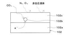
本実施形態の作用極側バインダ102cは、二酸化炭素を透過させることができる二酸化炭素透過性を有している。さらに、本実施形態の作用極側バインダ102cは、二酸化炭素含有ガスに含まれる複数種類のガスのうち、二酸化炭素を選択的に透過させることができる二酸化炭素選択透過性を有している。これに加えて、本実施形態の作用極側バインダ102cは、循環液体に対して非親和性を有している。
The working
図5に示すように、二酸化炭素含有ガスに含まれる二酸化炭素は作用極側バインダ102cを透過し、作用極側バインダ102cの内部に存在する二酸化炭素吸着材102bに到達することができる。一方、二酸化炭素含有ガスに含まれる二酸化炭素以外のガス(窒素、酸素等)は、二酸化炭素選択透過性を有する作用極側バインダ102cを透過できない。さらに、循環液体は、循環液体に対して非親和性を有する作用極側バインダ102cの内部に浸透しない。
As shown in FIG. 5, the carbon dioxide contained in the carbon dioxide-containing gas can permeate the working
作用極側バインダ102cとして、流動性を有さない非流動性物質を用いることができる。非流動性物質としては、ゲル状物質あるいは固体状物質を挙げることができる。ゲル状物質としては、例えばイオン液体ゲルを用いることができる。固体状物質としては、例えば固体電解質、あるいは導電性樹脂等を用いることができる。
A non-fluid substance that does not have fluidity can be used as the working
作用極側バインダ102cとして固体電解質を用いる場合には、二酸化炭素吸着材102bとの接触面積を増大させるために、高分子電解質等からなるアイオノマを用いることが望ましい。作用極側バインダ102cとして導電性樹脂を用いる場合には、導電性フィラーとしてAg等を含有するエポキシ樹脂やポリテトラフルオロエチレン(PTFE)、ポリフッ化ビニリデン(PVDF)等のフッ素樹脂等を用いることができる。
When a solid electrolyte is used as the working
作用極側バインダ102cの原材料は、流動性を有する液体状物質であってもよい。この場合には、作用極側バインダ102cの原材料に二酸化炭素吸着材102bを分散、混合させ、作用極側基材102aに含浸、塗布等によって付着させればよい。その後、作用極側バインダ102cの原材料を所定条件の下でゲル化あるいは固化させることができる。所定条件は、作用極側バインダ102cの原材料をゲル化あるいは固化させることができる特定圧力、特定温度、特定時間等の条件とすることができる。
The raw material of the working
図6に示すように、作用極側バインダ102cは、作用極側基材102aに形成された孔や凹凸の隙間に入り込み、そこで固定される。作用極側バインダ102cは、作用極側基材102aとの間において、投錨効果によって機械的な結合力を発生させることができる。
As shown in FIG. 6, the working
本実施形態では、作用極側バインダ102cとして、イオン液体をゲル化させたイオン液体ゲルを用いている。イオン液体ゲルは、高分子網目構造にイオン液体を保持したゲル状の構造体である。
In this embodiment, an ionic liquid gel made by gelling an ionic liquid is used as the working
イオン液体ゲルとしては、特開2015-25056号公報に開示されている構造体を好適に用いることができる。この構造体は、2種類の異なる高分子鎖からなる3次元網目構造にイオン液体が保持されている。3次元網目構造は、縮合重合で形成される第1網目構造と、ラジカル重合で形成される第2網目構造を含んでいる。 As an ionic liquid gel, the structure disclosed in JP 2015-25056 A can be suitably used. In this structure, an ionic liquid is held in a three-dimensional network structure made of two different types of polymer chains. The three-dimensional network structure includes a first network structure formed by condensation polymerization and a second network structure formed by radical polymerization.
縮合重合させるモノマとして、テトラエトキシオルトシリケート(TEOS)を用いることができる。TEOSは、縮合重合の架橋剤としても機能する。 Tetraethoxyorthosilicate (TEOS) can be used as a monomer for condensation polymerization. TEOS also functions as a cross-linking agent for condensation polymerization.
ラジカル重合させるモノマとしては、N,N-ジメチルアクリルアミド(DMAAm)を用いることができる。ラジカル重合では、架橋剤としてN,N´-メチレンビスアクリルアミド(MBAA)を用いることができ、開始剤として2,2´-アゾビス(イソブチロニトリル)(AIBN)を用いることができる。 N,N-dimethylacrylamide (DMAAm) can be used as a monomer for radical polymerization. In radical polymerization, N,N'-methylenebisacrylamide (MBAA) can be used as a crosslinking agent, and 2,2'-azobis(isobutyronitrile) (AIBN) can be used as an initiator.
イオン液体ゲルを構成するイオン液体は、第1網目構造を構成するモノマと第2網目構造を構成するモノマの溶媒として機能する。そして、第1網目構造と第2網目構造が形成された後は、第1網目構造と第2網目構造が互いに絡み合い、これらの網目構造にイオン液体が包含される。 The ionic liquid that constitutes the ionic liquid gel functions as a solvent for the monomer that constitutes the first network structure and the monomer that constitutes the second network structure. After the first network structure and the second network structure are formed, the first network structure and the second network structure become entangled with each other, and the ionic liquid is contained in these network structures.
イオン液体ゲルを構成するイオン液体としては、1-エチル-3-メチルイミダゾリウムビス(トリフルオロメタンスルホニル)イミド([EMIM][Tf2N])、1-ブチル-3-メチルイミダゾリウムビス(トリフルオロメタンスルホニル)イミド([BMIM][Tf2N])、1-ブチル-3-メチルイミダゾリウムテトラフルオロホウ酸塩([BMIM][BF4])等を用いることができる。 Examples of ionic liquids that can be used to form the ionic liquid gel include 1-ethyl-3-methylimidazolium bis(trifluoromethanesulfonyl)imide ([EMIM][Tf 2 N]), 1-butyl-3-methylimidazolium bis(trifluoromethanesulfonyl)imide ([BMIM][Tf 2 N]), and 1-butyl-3-methylimidazolium tetrafluoroborate ([BMIM][BF 4 ]).
図4に戻り、対極103は、作用極102と同様の構成を有しており、対極側基材103a、電気活性補助材103b、対極側バインダ103cが設けられている。
Returning to FIG. 4, the
対極側基材103aは、導電性材料であり、作用極側基材102aと同じ材料を用いてもよく、異なる材料を用いてもよい。対極側バインダ103cは、電気活性補助材103bを対極側基材103aに保持させることができ、かつ、導電性を有する材料であればよい。対極側バインダ103cは、作用極側バインダ102cと同じ材料を用いてもよく、異なる材料を用いてもよい。
The counter
電気活性補助材103bは、二酸化炭素吸着材102bと酸化還元状態が逆になり、二酸化炭素吸着材102bとの間で電子の授受を行う補助的な電気活性種である。電気活性補助材103bとしては、例えば金属イオンの価数が変化することで、電子の授受を可能とする金属錯体を用いることができる。このような金属錯体としては、フェロセン、ニッケロセン、コバルトセン等のシクロペンタジエニル金属錯体、あるいはポルフィリン金属錯体等を挙げることができる。
The electroactive
絶縁層104は、作用極102と対極103の間に配置されており、作用極102と対極103を分離している。絶縁層104は、作用極102と対極103の物理的な接触を防ぎ、電気的短絡を抑制する。
The insulating
絶縁層104としては、セパレータ、あるいは空気等の気体層を用いることができる。本実施形態では、絶縁層104として多孔質体のセパレータを用いている。セパレータの材料は、セルロース膜やポリマ、ポリマとセラミックの複合材料等からなるセパレータを用いることができる。
The insulating
図4に示すように、作用極102と対極103の間には、イオン伝導性部材106が設けられている。イオン伝導性部材106は、絶縁層104を介して作用極側基材102aと対極側基材103aとの間に設けられている。
As shown in FIG. 4, an ion
イオン伝導性部材106は、作用極側基材102aの内部で二酸化炭素吸着材102bと接触している。イオン伝導性部材106は、イオン伝導性を有しており、二酸化炭素吸着材102bへの導電を促進する。イオン伝導性部材106に含まれるイオンは、二酸化炭素吸着材102bに含まれる二酸化炭素と結合する官能基と直接反応しない。
The ion
イオン伝導性部材106は、流動性を有さない非流動性物質を好適に用いることができる。非流動性物質としては、ゲル状物質あるいは固体状物質を挙げることができ、例えばイオン液体ゲルや固体電解質等を用いることができる。イオン伝導性部材106は、作用極側バインダ102cと同じ材料を用いてもよく、作用極側バインダ102cと異なる材料を用いてもよい。
The ion
次に、液体回路14について図1および図7を用いて説明する。図1に示すように、液体回路14は、液体タンク141、液体供給流路142、液体供給ポンプ143、液体排出流路144、および液体排出ポンプ145を有している。
Next, the
液体タンク141は、循環液体を貯留するタンクである。液体供給流路142は、液体タンク141の出口側と吸着部100の液体流入口100cとを接続して、液体タンク141から吸着部100に循環液体を供給する流路である。
The
液体供給ポンプ143は、液体供給流路142に設けられるとともに、液体タンク141から吸着部100へ循環液体を圧送するポンプである。液体供給ポンプ143は、制御装置15から出力される制御電圧によって、回転数(すなわち、圧送能力)が制御される。
The
液体排出流路144は、吸着部100の液体流出口100dと液体タンク141の入口側とを接続して、吸着部100から液体タンク141に循環液体を排出させる流路である。すなわち、液体排出流路144は、吸着部100内の循環液体を吸着部100の外部に排出する流路である。
The liquid
液体排出ポンプ145は、液体排出流路144に設けられるとともに、吸着部100から液体タンク141へ循環液体を圧送するポンプである。液体排出ポンプ145は、制御装置15から出力される制御電圧によって、回転数(すなわち、圧送能力)が制御される。
The
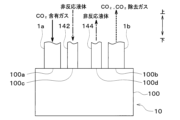
図7に示すように、液体供給流路142および液体排出流路144の各々は、吸着部100の鉛直方向下方側に接続されている。本実施形態では、液体供給流路142および液体排出流路144の各々は、吸着部100の下端面(すなわち、底面)に接続されている。
As shown in FIG. 7, each of the liquid
ガス供給流路1aおよびガス排出流路1bの各々は、吸着部100の鉛直方向上方側に接続されている。本実施形態では、ガス供給流路1aおよびガス排出流路1bの各々は、吸着部100の上端面に接続されている。
Each of the gas
次に、本実施形態の二酸化炭素回収システム1の作動について図8~図10を用いて説明する。図8に示すように、二酸化炭素回収システム1は、二酸化炭素吸着モード、除去ガス排出モード、および二酸化炭素回収モードを実行可能に構成されている。二酸化炭素回収システム1は、二酸化炭素吸着モード、除去ガス排出モード、二酸化炭素回収モード、二酸化炭素吸着モード、除去ガス排出モード、二酸化炭素回収モード、…の順に切り替えて作動する。二酸化炭素回収システム1の作動は、制御装置15によって制御される。
Next, the operation of the carbon
まず、二酸化炭素吸着モードについて説明する。図9に示すように、二酸化炭素吸着モードでは、圧縮機11が作動して吸着部100に二酸化炭素含有ガスが供給される。二酸化炭素吸着モードでは、作用極102と対極103の間に印加される電圧を第1の電圧V1とする。これにより、対極103の電気活性補助材103bによる電子供与と、作用極102の二酸化炭素吸着材102bの電子求引を同時に実現できる。
First, the carbon dioxide adsorption mode will be described. As shown in FIG. 9, in the carbon dioxide adsorption mode, the
対極103の電気活性補助材103bは電子を放出して酸化状態となり、対極103から作用極102に電子が供給される。作用極102の二酸化炭素吸着材102bは、電子を受け取って還元状態となる。
The electrically active
還元状態となった二酸化炭素吸着材102bは二酸化炭素の結合力が高くなり、二酸化炭素含有ガスに含まれる二酸化炭素を結合して吸着する。これにより、二酸化炭素回収装置10は、二酸化炭素含有ガスから二酸化炭素を回収することができる。
The
次に、除去ガス排出モードについて説明する。図8に示すように、除去ガス排出モードは、液体供給モードおよび液体排出モードを有している。二酸化炭素回収システム1は、液体供給モードを実行した後、液体排出モードを実行する。
Next, the removed gas discharge mode will be described. As shown in FIG. 8, the removed gas discharge mode has a liquid supply mode and a liquid discharge mode. The carbon
除去ガス排出モード(すなわち、液体供給モードおよび液体排出モードの双方)では、作用極102と対極103の間に第1の電圧V1を印加し続ける。除去ガス排出モードでは、圧縮機11が作動停止し、吸着部100への二酸化炭素含有ガスの供給が停止する。
In the removal gas discharge mode (i.e., both the liquid supply mode and the liquid discharge mode), the first voltage V1 continues to be applied between the working
液体供給モードでは、液体供給ポンプ143が作動して、液体タンク141から循環液体が吸着部100へ供給される。このとき、吸着部100内の二酸化炭素は、二酸化炭素吸着材102bに吸着されたままの状態であり、循環液体に溶解したり、循環液体と化学反応を起こしたりすることはない。
In the liquid supply mode, the
液体排出モードでは、液体供給ポンプ143が作動停止し、吸着部100への循環液体の供給が停止する。さらに、液体排出モードでは、液体排出ポンプ145が作動して、循環液体が吸着部100から排出されて液体タンク141にて回収される。このとき、吸着部100から排出される循環液体の流れにより、二酸化炭素を含まない二酸化炭素除去ガスが吸着部100からガス排出流路1bに排出される。液体排出モードでは、流路切替弁12は、ガス排出流路1bを大気側に切り替えており、吸着部100から排出された二酸化炭素除去ガスは大気に排出される。
In the liquid discharge mode, the
次に、二酸化炭素回収モードについて説明する。図10に示すように、二酸化炭素回収モードでは、液体排出ポンプ145が作動停止し、吸着部100からの循環液体の排出が停止する。二酸化炭素回収モードでは、作用極102と対極103の間に印加される電圧を第2の電圧V2とする。これにより、作用極102の二酸化炭素吸着材102bによる電子供与と、対極103の電気活性補助材103bの電子求引を同時に実現できる。
Next, the carbon dioxide capture mode will be described. As shown in FIG. 10, in the carbon dioxide capture mode, the
作用極102の二酸化炭素吸着材102bは、電子を放出して酸化状態となる。二酸化炭素吸着材102bは、二酸化炭素の結合力が低下し、二酸化炭素を脱離して放出する。対極103の電気活性補助材103bは、電子を受け取って還元状態となる。
The
二酸化炭素吸着材102bから放出された二酸化炭素は、吸着部100から排出される。流路切替弁12は、ガス排出流路1bを二酸化炭素利用装置13側に切り替えており、吸着部100から排出された二酸化炭素は二酸化炭素利用装置13に供給される。
The carbon dioxide released from the
本実施形態では、液体供給流路142および液体供給ポンプ143が、循環液体を吸着部100内に供給する供給部の一例に相当する。また、ガス排出流路1b、液体排出流路144および液体排出ポンプ145が、供給部から供給された循環液体および二酸化炭素除去ガスを吸着部100から排出する排出部の一例に相当する。
In this embodiment, the liquid
以上説明したように、本実施形態の二酸化炭素回収システム1は、供給部である液体供給流路142および液体供給ポンプ143、並びに、排出部であるガス排出流路1b、液体排出流路144および液体排出ポンプ145を有している。そして、二酸化炭素回収システム1は、作用極102と対極103との間に電圧が印加された状態で、循環液体を吸着部100内に供給した後、循環液体および二酸化炭素除去ガスを吸着部100から排出する除去ガス排出モードを実行可能に構成されている。
As described above, the carbon
これによれば、吸着部100から、循環液体とともに二酸化炭素除去ガスを排出することができる。その結果、吸着部100内の二酸化炭素の純度を高めることができるので、回収される二酸化炭素の純度を向上させることができる。
This allows the carbon dioxide removal gas to be discharged from the
また、本実施形態では、電気化学セル101における作用極102の二酸化炭素吸着材102bは、作用極側バインダ102cに覆われている。これにより、二酸化炭素吸着材102bが作用極側基材102aから剥離しにくくなり、電気化学セル101の二酸化炭素吸着量が経時的に低下することを抑制できる。
In addition, in this embodiment, the
また、本実施形態の作用極側バインダ102cは、循環液体に対する非親和性を有している。このため、循環液体の存在下においても、循環液体が作用極側バインダ102cに到達することを抑制できる。これにより、循環液体が二酸化炭素吸着材102bと優先的に反応することを抑制でき、二酸化炭素吸着材102bの二酸化炭素吸着量を増大させることができる。
In addition, the working
また、本実施形態では、作用極側バインダ102cは、二酸化炭素透過性を有している。このため、二酸化炭素が作用極側バインダ102cを透過して二酸化炭素吸着材102bに到達することができる。この結果、二酸化炭素吸着材102bが作用極側バインダ102cに覆われている場合でも、二酸化炭素吸着材102bによる二酸化炭素の回収が可能となる。
In addition, in this embodiment, the working
また、本実施形態では、作用極側バインダ102cとしてイオン液体ゲルを用いている。このため、作用極側バインダ102cに、循環液体に対する非親和性や二酸化炭素透過性を容易に付与することが可能となる。さらに、作用極側バインダ102cに、常温常圧における非揮発性を付与することも可能となる。
In addition, in this embodiment, an ionic liquid gel is used as the working
また、本実施形態の二酸化炭素吸着材102bは、循環液体に対する非親和性を有している。このため、循環液体が二酸化炭素吸着材102bと優先的に反応することを抑制でき、二酸化炭素吸着材102bの二酸化炭素吸着量を増大させることができる。
In addition, the
また、本実施形態の二酸化炭素回収システム1では、液体供給流路142および液体排出流路144の各々を、吸着部100の鉛直方向下方側に接続している。また、ガス排出流路1bを、吸着部100の鉛直方向上方側に接続している。これによれば、吸着部100内において液体と気体とが相分離しやすくなるので、気体である二酸化炭素除去ガスを吸着部100から容易に排出することが可能となる。
In addition, in the carbon
(第2実施形態)
次に、本発明の第2実施形態について図11に基づいて説明する。本実施形態では、第1実施形態に対して、液体供給流路142および液体排出流路144の吸着部100への接続位置を変更している。
Second Embodiment
Next, a second embodiment of the present invention will be described with reference to Fig. 11. In this embodiment, the connection positions of the liquid
図11に示すように、本実施形態の二酸化炭素回収システム1では、液体供給流路142および液体排出流路144の各々は、吸着部100の鉛直方向上方側に接続されている。本実施形態では、液体供給流路142および液体排出流路144の各々は、吸着部100の上端面に接続されている。
As shown in FIG. 11, in the carbon
以上説明したように、本実施形態の二酸化炭素回収システム1では、液体供給流路142、液体排出流路144およびガス排出流路1bを、吸着部100の鉛直方向上方側に接続している。これによれば、吸着部100に循環液体を供給し易くするとともに、吸着部100から気体である二酸化炭素除去ガスを排出し易くすることが可能となる。
As described above, in the carbon
(第3実施形態)
次に、本発明の第3実施形態について図12に基づいて説明する。本実施形態では、第1実施形態に対して、ガス供給流路1a、ガス排出流路1b、液体供給流路142および液体排出流路144の吸着部100への接続位置を変更している。
Third Embodiment
Next, a third embodiment of the present invention will be described with reference to Fig. 12. In this embodiment, the positions at which the gas
図12に示すように、本実施形態の二酸化炭素回収システム1では、ガス供給流路1a、ガス排出流路1b、液体供給流路142および液体排出流路144の各々は、吸着部100の鉛直方向中央部に接続されている。
As shown in FIG. 12, in the carbon
本実施形態では、吸着部100は、水平方向に延びる形状に形成されている。すなわち、二酸化炭素回収装置10は、吸着部100の長手方向が水平方向と平行となるように配置されている。ガス供給流路1aおよび液体供給流路142は、吸着部100の長手方向の一端側に接続されている。ガス排出流路1bおよび液体排出流路144は、吸着部100の長手方向の他端側に接続されている。
In this embodiment, the
以上説明したように、本実施形態の二酸化炭素回収システム1では、ガス供給流路1a、ガス排出流路1b、液体供給流路142および液体排出流路144の各々を、吸着部100の鉛直方向中央部に接続している。これによれば、二酸化炭素回収システム1の省スペース化を図ることができる。
As described above, in the carbon
(第4実施形態)
次に、本発明の第4実施形態について図13に基づいて説明する。本実施形態では、第1実施形態に対して、二酸化炭素回収装置10の構成を変更している。
Fourth Embodiment
Next, a fourth embodiment of the present invention will be described with reference to Fig. 13. In this embodiment, the configuration of the carbon
図13に示すように、本実施形態の二酸化炭素回収システム1では、二酸化炭素回収装置10は、温度調整部107を有している。温度調整部107は、二酸化炭素を二酸化炭素吸着材102bに吸着させる二酸化炭素吸着時に、被覆材である作用極側バインダ102cの温度を上昇させる。また、温度調整部107は、二酸化炭素吸着材102bから二酸化炭素を脱離させるに二酸化炭素脱離時に作用極側バインダ102cの温度を下降させる。温度調整部107は、制御装置15から出力される制御電圧によって、その作動が制御される。
As shown in FIG. 13, in the carbon
ここで、本実施形態では、作用極側バインダ102cとして、イオン液体をゲル化したイオン液体ゲルを用いている。イオン液体は、高温において二酸化炭素の溶解性が上がり、低温において二酸化炭素の溶解性が下がる特性を有している。
In this embodiment, an ionic liquid gel made by gelling an ionic liquid is used as the working
このため、本実施形態の二酸化炭素回収システム1によれば、二酸化炭素吸着時に、温度調整部107によって作用極側バインダ102cの温度を上昇させることで、作用極側バインダ102c内に二酸化炭素が溶けやすくなる。これにより、二酸化炭素吸着材102bへの二酸化炭素の吸着を促進できる。
Therefore, according to the carbon
さらに、二酸化炭素脱離時に、温度調整部107によって作用極側バインダ102cの温度を低下させることで、作用極側バインダ102c内に二酸化炭素が溶け難くなる。これにより、二酸化炭素吸着材102bからの二酸化炭素の脱離を促進できる。
Furthermore, when carbon dioxide is desorbed, the temperature of the working
(他の実施形態)
本発明は上述の実施形態に限定されることなく、本発明の趣旨を逸脱しない範囲内で、以下のように種々変形可能である。また、上記各実施形態に開示された手段は、実施可能な範囲で適宜組み合わせてもよい。
Other Embodiments
The present invention is not limited to the above-described embodiment, and various modifications can be made without departing from the spirit of the present invention. Furthermore, the means disclosed in each of the above-described embodiments may be appropriately combined within the scope of feasibility.
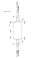
(1)上述した実施形態では、電気化学セル101の作用極102、対極103、絶縁層104をそれぞれ板状部材としたが、図14に示すように、作用極102、対極103、絶縁層104をそれぞれ円筒状部材としてもよい。この場合には、作用極102を最も内側に配置し、対極103を最も外側に配置し、作用極102と対極103の間に絶縁層104を配置すればよい。これにより、作用極102の内側に形成される空間を二酸化炭素含有ガスが通過するガス流路とすることができる。
(1) In the above-described embodiment, the working
(2)上述した実施形態では、作用極側バインダ102cとして、イオン液体をゲル化したイオン液体ゲルを用いた例について説明したが、作用極側バインダ102cはイオン液体ゲルに限定されない。例えば、作用極側バインダ102cとして、イオン液体を用いてもよい。
(2) In the above embodiment, an example was described in which an ionic liquid gel made by gelling an ionic liquid was used as the working
(3)上述した実施形態では、循環液体として、二酸化炭素に対して非化学反応性および不溶性を有している液体を用いたが、循環液体は、必ずしも二酸化炭素に対して非化学反応性および不溶性を有していなくてもよい。 (3) In the above-described embodiment, a liquid that is non-chemically reactive and insoluble in carbon dioxide is used as the circulating liquid, but the circulating liquid does not necessarily have to be non-chemically reactive and insoluble in carbon dioxide.
例えば、循環液体として、水を用いてもよい。この場合、二酸化炭素吸着材102bおよび作用極側バインダ102cは、疎水性を有していてもよい。
For example, water may be used as the circulating liquid. In this case, the
1b ガス排出流路(排出部)
100 吸着部
142 液体供給流路(供給部)
143 液体供給ポンプ(供給部)
144 液体排出流路(排出部)
145 液体排出ポンプ(排出部)
1b Gas exhaust flow path (exhaust section)
100
143 Liquid supply pump (supply section)
144 Liquid discharge flow path (discharge section)
145 Liquid discharge pump (discharge section)
Claims (8)
作用極(102)と対極(103)とを有するとともに、前記作用極と前記対極との間に電圧が印加されることで、前記対極から前記作用極に電子が供給され、前記作用極は電子が供給されることに伴って二酸化炭素と結合する電気化学セル(101)と、
前記電気化学セルが収容されるとともに、前記二酸化炭素含有ガスが導入される吸着部(100)と、
前記作用極と前記対極との間に電圧が印加された状態で、液体を前記吸着部内に供給する供給部(142、143)と、
前記作用極と前記対極との間に電圧が印加された状態で、前記供給部から供給された前記液体、および前記二酸化炭素含有ガスから二酸化炭素が分離された後の二酸化炭素除去ガスを前記吸着部から排出する排出部(1b、144、145)と、を備え、
前記作用極は、電極基材(102a)と、二酸化炭素吸着材(102b)と、を有しており、
前記作用極と前記対極との間に電圧が印加されることで、前記対極から前記作用極に電子が供給され、前記二酸化炭素吸着材は電子が供給されることに伴って二酸化炭素と結合しており、
前記二酸化炭素吸着材は、被覆材(102c)に覆われている二酸化炭素回収システム。 A carbon dioxide capture system that separates carbon dioxide from a carbon dioxide-containing gas that contains carbon dioxide by an electrochemical reaction,
an electrochemical cell (101) having a working electrode (102) and a counter electrode (103), in which, when a voltage is applied between the working electrode and the counter electrode, electrons are supplied from the counter electrode to the working electrode, and the working electrode is bonded to carbon dioxide as the electrons are supplied;
an adsorption section (100) in which the electrochemical cell is housed and into which the carbon dioxide-containing gas is introduced;
A supply unit (142, 143) that supplies a liquid into the adsorption unit while a voltage is applied between the working electrode and the counter electrode;
and a discharge section (1b, 144, 145) that discharges, from the adsorption section, the liquid supplied from the supply section and the carbon dioxide-removed gas obtained after carbon dioxide is separated from the carbon dioxide-containing gas , while a voltage is applied between the working electrode and the counter electrode;
The working electrode has an electrode substrate (102a) and a carbon dioxide adsorbent (102b),
When a voltage is applied between the working electrode and the counter electrode, electrons are supplied from the counter electrode to the working electrode, and the carbon dioxide adsorbent is bonded to carbon dioxide as the electrons are supplied,
A carbon dioxide capture system, wherein the carbon dioxide adsorbent is covered with a covering material (102c) .
前記電圧印加部、前記供給部および前記排出部の作動を制御する制御部(15)と、を備え、
前記制御部は、前記作用極と前記対極との間に電圧を印加した状態で、前記供給部によって前記液体を前記吸着部内に供給した後、前記排出部によって前記液体および前記二酸化炭素除去ガスを前記吸着部から排出する請求項1に記載の二酸化炭素回収システム。 Furthermore, a voltage application unit (105) that applies a voltage between the working electrode and the counter electrode;
A control unit (15) that controls the operation of the voltage application unit, the supply unit, and the discharge unit,
The carbon dioxide capture system according to claim 1, wherein the control unit supplies the liquid into the adsorption unit using the supply unit while a voltage is applied between the working electrode and the counter electrode, and then discharges the liquid and the carbon dioxide-removed gas from the adsorption unit using the discharge unit.
前記排出部は、
前記吸着部の上方側に接続されるとともに、前記吸着部内の前記二酸化炭素除去ガスを外部に排出するガス排出流路(1b)と、
前記吸着部の下方側に接続されるとともに、前記吸着部内の前記液体を外部に排出する液体排出流路(144)と、を有している請求項1ないし5のいずれか1つに記載の二酸化炭素回収システム。 the supply unit is connected to a lower side of the adsorption unit and has a liquid supply flow path (142) that supplies the liquid to the adsorption unit;
The discharge section is
a gas exhaust passage (1b) connected to an upper side of the adsorption section and configured to exhaust the carbon dioxide-removed gas in the adsorption section to the outside;
6. The carbon dioxide capture system according to claim 1 , further comprising: a liquid discharge passage (144) connected to a lower side of the adsorption section and discharging the liquid in the adsorption section to the outside.
前記排出部は、
前記吸着部の上方側に接続されるとともに、前記吸着部内の前記二酸化炭素除去ガスを外部に排出するガス排出流路(1b)と、
前記吸着部の上方側に接続されるとともに、前記吸着部内の前記液体を外部に排出する液体排出流路(144)と、を有している請求項1ないし5のいずれか1つに記載の二酸化炭素回収システム。 the supply unit is connected to an upper side of the adsorption unit and has a liquid supply flow path (142) that supplies the liquid to the adsorption unit;
The discharge section is
a gas exhaust passage (1b) connected to an upper side of the adsorption section and configured to exhaust the carbon dioxide-removed gas in the adsorption section to the outside;
6. The carbon dioxide capture system according to claim 1 , further comprising: a liquid discharge passage (144) connected to an upper side of the adsorption section and discharging the liquid in the adsorption section to the outside.
前記排出部は、
前記吸着部の鉛直方向中央部に接続されるとともに、前記吸着部内の前記二酸化炭素除去ガスを外部に排出するガス排出流路(1b)と、
前記吸着部の鉛直方向中央部に接続されるとともに、前記吸着部内の前記液体を外部に排出する液体排出流路(144)と、を有している請求項1ないし5のいずれか1つに記載の二酸化炭素回収システム。 The supply unit has a liquid supply flow path (142) connected to a vertical center of the suction unit and supplying the liquid to the suction unit;
The discharge section is
a gas exhaust passage (1b) connected to a vertical center of the adsorption section and configured to exhaust the carbon dioxide-removed gas in the adsorption section to the outside;
6. The carbon dioxide capture system according to claim 1 , further comprising: a liquid discharge flow path (144) connected to a vertical center portion of the adsorption section and discharging the liquid in the adsorption section to the outside.
Priority Applications (4)
| Application Number | Priority Date | Filing Date | Title |
|---|---|---|---|
| JP2021030389A JP7619084B2 (en) | 2021-02-26 | 2021-02-26 | Carbon Dioxide Capture System |
| EP22156814.0A EP4049745A1 (en) | 2021-02-26 | 2022-02-15 | Carbon dioxide recovery apparatus, system and method |
| CN202210166411.2A CN114950069A (en) | 2021-02-26 | 2022-02-23 | Carbon dioxide recovery device, system and method |
| US17/681,896 US20220274056A1 (en) | 2021-02-26 | 2022-02-28 | Carbon dioxide recovery apparatus, system and method |
Applications Claiming Priority (1)
| Application Number | Priority Date | Filing Date | Title |
|---|---|---|---|
| JP2021030389A JP7619084B2 (en) | 2021-02-26 | 2021-02-26 | Carbon Dioxide Capture System |
Publications (2)
| Publication Number | Publication Date |
|---|---|
| JP2022131439A JP2022131439A (en) | 2022-09-07 |
| JP7619084B2 true JP7619084B2 (en) | 2025-01-22 |
Family
ID=80682280
Family Applications (1)
| Application Number | Title | Priority Date | Filing Date |
|---|---|---|---|
| JP2021030389A Active JP7619084B2 (en) | 2021-02-26 | 2021-02-26 | Carbon Dioxide Capture System |
Country Status (4)
| Country | Link |
|---|---|
| US (1) | US20220274056A1 (en) |
| EP (1) | EP4049745A1 (en) |
| JP (1) | JP7619084B2 (en) |
| CN (1) | CN114950069A (en) |
Families Citing this family (1)
| Publication number | Priority date | Publication date | Assignee | Title |
|---|---|---|---|---|
| JP7459755B2 (en) * | 2020-10-20 | 2024-04-02 | 株式会社デンソー | Electrochemical Cells and Carbon Dioxide Capture Systems |
Citations (7)
| Publication number | Priority date | Publication date | Assignee | Title |
|---|---|---|---|---|
| JP2003306788A (en) | 2002-04-18 | 2003-10-31 | Meidensha Corp | Method, apparatus, and system for removing carbon dioxide |
| JP2008528285A (en) | 2005-02-03 | 2008-07-31 | サーマル エナジー システムズ リミテッド | Gas separation and compression equipment |
| WO2012144189A1 (en) | 2011-04-21 | 2012-10-26 | パナソニック株式会社 | Device for adsorbing and emitting carbon dioxide |
| JP2015036128A (en) | 2013-08-12 | 2015-02-23 | 住友化学株式会社 | Acidic gas adsorption/desorption device |
| JP2018153173A (en) | 2017-03-16 | 2018-10-04 | 株式会社東芝 | Carbon dioxide fixing device and fuel production system |
| JP2018533470A (en) | 2015-10-27 | 2018-11-15 | マサチューセッツ インスティテュート オブ テクノロジー | Electrochemical process for gas separation |
| US20190030485A1 (en) | 2017-07-25 | 2019-01-31 | Hamilton Sundstrand Corporation | Electrochemical separator |
Family Cites Families (4)
| Publication number | Priority date | Publication date | Assignee | Title |
|---|---|---|---|---|
| JP5910076B2 (en) * | 2011-12-27 | 2016-04-27 | 住友化学株式会社 | Alkaline battery with a site capable of adsorbing and desorbing carbon dioxide |
| JP6103708B2 (en) | 2013-07-25 | 2017-03-29 | 国立大学法人神戸大学 | Interpenetrating network structure containing ionic liquid and method for producing the same |
| US20180265899A1 (en) * | 2017-03-16 | 2018-09-20 | Kabushiki Kaisha Toshiba | Carbon dioxide fixation device and fuel production system |
| US12059646B2 (en) * | 2018-12-07 | 2024-08-13 | Commonwealth Scientific And Industrial Research Organisation | Adsorption and desorption apparatus |
-
2021
- 2021-02-26 JP JP2021030389A patent/JP7619084B2/en active Active
-
2022
- 2022-02-15 EP EP22156814.0A patent/EP4049745A1/en not_active Withdrawn
- 2022-02-23 CN CN202210166411.2A patent/CN114950069A/en not_active Withdrawn
- 2022-02-28 US US17/681,896 patent/US20220274056A1/en not_active Abandoned
Patent Citations (7)
| Publication number | Priority date | Publication date | Assignee | Title |
|---|---|---|---|---|
| JP2003306788A (en) | 2002-04-18 | 2003-10-31 | Meidensha Corp | Method, apparatus, and system for removing carbon dioxide |
| JP2008528285A (en) | 2005-02-03 | 2008-07-31 | サーマル エナジー システムズ リミテッド | Gas separation and compression equipment |
| WO2012144189A1 (en) | 2011-04-21 | 2012-10-26 | パナソニック株式会社 | Device for adsorbing and emitting carbon dioxide |
| JP2015036128A (en) | 2013-08-12 | 2015-02-23 | 住友化学株式会社 | Acidic gas adsorption/desorption device |
| JP2018533470A (en) | 2015-10-27 | 2018-11-15 | マサチューセッツ インスティテュート オブ テクノロジー | Electrochemical process for gas separation |
| JP2018153173A (en) | 2017-03-16 | 2018-10-04 | 株式会社東芝 | Carbon dioxide fixing device and fuel production system |
| US20190030485A1 (en) | 2017-07-25 | 2019-01-31 | Hamilton Sundstrand Corporation | Electrochemical separator |
Also Published As
| Publication number | Publication date |
|---|---|
| JP2022131439A (en) | 2022-09-07 |
| EP4049745A1 (en) | 2022-08-31 |
| US20220274056A1 (en) | 2022-09-01 |
| CN114950069A (en) | 2022-08-30 |
Similar Documents
| Publication | Publication Date | Title |
|---|---|---|
| JP7459755B2 (en) | Electrochemical Cells and Carbon Dioxide Capture Systems | |
| JP7453651B2 (en) | Electrochemical cells and carbon dioxide capture systems | |
| JP7750000B2 (en) | Carbon dioxide capture system | |
| JP7694141B2 (en) | Carbon Dioxide Capture System | |
| JP7619084B2 (en) | Carbon Dioxide Capture System | |
| US20250170516A1 (en) | Carbon dioxide recovery system | |
| JP2023176214A (en) | Gas recovery system and electrode membrane manufacturing method | |
| JP2023173789A (en) | carbon dioxide capture system | |
| CN119604352A (en) | Gas recovery system | |
| US20230381715A1 (en) | Carbon dioxide recovery system | |
| US20230387425A1 (en) | Electrochemical cell, gas recovery system equipped with electrochemical cell, and method of manufacturing electrochemical cell | |
| US20250135395A1 (en) | Carbon dioxide recovery system | |
| US20250288952A1 (en) | Electrochemical cell and carbon dioxide recovery system | |
| JP2024011778A (en) | electrochemical cell | |
| JP2024007764A (en) | electrochemical cell | |
| JP2025008827A (en) | Carbon Dioxide Capture Equipment | |
| JP2024137687A (en) | Electrochemical Cell | |
| JP2024004909A (en) | carbon dioxide capture system | |
| JP2024011776A (en) | electrochemical cell |
Legal Events
| Date | Code | Title | Description |
|---|---|---|---|
| A621 | Written request for application examination |
Free format text: JAPANESE INTERMEDIATE CODE: A621 Effective date: 20231211 |
|
| A977 | Report on retrieval |
Free format text: JAPANESE INTERMEDIATE CODE: A971007 Effective date: 20240725 |
|
| A131 | Notification of reasons for refusal |
Free format text: JAPANESE INTERMEDIATE CODE: A131 Effective date: 20240903 |
|
| A521 | Request for written amendment filed |
Free format text: JAPANESE INTERMEDIATE CODE: A523 Effective date: 20241011 |
|
| A521 | Request for written amendment filed |
Free format text: JAPANESE INTERMEDIATE CODE: A523 Effective date: 20241029 |
|
| TRDD | Decision of grant or rejection written | ||
| A01 | Written decision to grant a patent or to grant a registration (utility model) |
Free format text: JAPANESE INTERMEDIATE CODE: A01 Effective date: 20241210 |
|
| A61 | First payment of annual fees (during grant procedure) |
Free format text: JAPANESE INTERMEDIATE CODE: A61 Effective date: 20241223 |
|
| R150 | Certificate of patent or registration of utility model |
Ref document number: 7619084 Country of ref document: JP Free format text: JAPANESE INTERMEDIATE CODE: R150 |