JP7617618B2 - On-site mixing manufacturing unit for track construction, and track construction method using this on-site mixing manufacturing unit - Google Patents
On-site mixing manufacturing unit for track construction, and track construction method using this on-site mixing manufacturing unit Download PDFInfo
- Publication number
- JP7617618B2 JP7617618B2 JP2021031627A JP2021031627A JP7617618B2 JP 7617618 B2 JP7617618 B2 JP 7617618B2 JP 2021031627 A JP2021031627 A JP 2021031627A JP 2021031627 A JP2021031627 A JP 2021031627A JP 7617618 B2 JP7617618 B2 JP 7617618B2
- Authority
- JP
- Japan
- Prior art keywords
- aggregate
- mixer
- belt conveyor
- unit
- site
- Prior art date
- Legal status (The legal status is an assumption and is not a legal conclusion. Google has not performed a legal analysis and makes no representation as to the accuracy of the status listed.)
- Active
Links
Images

Landscapes
- Machines For Laying And Maintaining Railways (AREA)
- On-Site Construction Work That Accompanies The Preparation And Application Of Concrete (AREA)
- Preparation Of Clay, And Manufacture Of Mixtures Containing Clay Or Cement (AREA)
Description
開示する技術は、主に、電車が走行するレール周辺で行われる工事(軌道工事)を対象とする、現場練り製造ユニット、および、この現場練り製造ユニットを用いた軌道工事方法に関する。 The technology disclosed relates to an on-site mixing manufacturing unit that is primarily intended for construction work (track construction) carried out around the rails on which trains run, and a track construction method that uses this on-site mixing manufacturing unit.
本出願人は、先に、既設の構造物の補修工事や改修工事などに好適な、コンクリートの現場練り製造ユニットを提案している(特許文献1)。 The applicant has previously proposed an on-site concrete mixing and manufacturing unit that is suitable for repair and renovation work on existing structures (Patent Document 1).
その現場練り製造ユニットでは、小型トラックの荷台に積載できて乗り降ろしも可能なユニット台の上に、ホッパーやミキサーなど、現場練りに必要な関連装置が効率よく一体に組み込まれている。従って、この現場練り製造ユニットによれば、オフィスビル内の改装工事など、ミキサー車の乗り入れ自体ができない小規模な工事現場でも、簡単にコンクリートの現場練りが行える。 The on-site mixing production unit efficiently integrates all the related equipment required for on-site mixing, such as a hopper and mixer, onto a unit platform that can be loaded onto the bed of a small truck and easily accessed by passengers. Therefore, with this on-site mixing production unit, on-site mixing of concrete can be easily carried out even at small construction sites where a mixer truck cannot even be brought in, such as renovation work inside an office building.
軌道工事に関する先行技術としては、例えば特許文献2がある。特許文献2には、軌道の両側にレールを別途敷設し、そのレールを用いて、クレーン等を搭載した作業架台を移動させながら、軌道の横に設置されている電柱等を取り替える方法が開示されている。 Patent Document 2 is an example of prior art related to track construction. Patent Document 2 discloses a method in which rails are laid separately on both sides of the track, and a work platform equipped with a crane or the like is moved using the rails to replace utility poles and other items installed next to the track.
軌道工事は、日中は電車が走行するため、夜間しか行えない。更に、その工期も夜間の所定期間に限られるため、短時間で、しかも確実に、所定の工事を完了させる必要がある。工事の遅延はダイヤの乱れを招くおそれがあるため、許容できない。 Track construction work can only be done at night, because trains run during the day. Furthermore, the construction period is limited to a designated period at night, so the work must be completed quickly and reliably. Construction delays are unacceptable, as they could disrupt the train schedule.
例えば、電柱の建て替え工事の場合には、まず、電柱の設置場所に縦穴を掘削し、その中に枠材を設置する。電柱の下部をその枠材に組み付けた後、コンクリートを打設する。そうして、コンクリートが硬化した後、電柱の上部を組み付ければ、工事は完了となる。 For example, when replacing a utility pole, first a vertical hole is excavated at the site where the pole will be installed and a frame is placed inside it. The lower part of the pole is then attached to the frame, and concrete is poured. Once the concrete has hardened, the upper part of the pole is attached, and the work is complete.
このような電柱の建て替え工事においても、従来は、ミキサー車で工場から搬送される生コンが用いられていた。しかし、夜間では、人手の確保の面で生コンの調達自体が難しい。そのうえ、工事の進捗に合わせて、適切なタイミングで適量の生コンを準備することは、作業現場によっては極めて困難なものとなる。特に、必要とされるコンクリートの量が少ない場合は尚更である。 Traditionally, even in such utility pole replacement work, ready-mixed concrete transported from a factory in a mixer truck has been used. However, procuring ready-mixed concrete at night is difficult in terms of manpower availability. Furthermore, depending on the work site, it can be extremely difficult to prepare the right amount of ready-mixed concrete at the right time in line with the progress of the work. This is especially true when only a small amount of concrete is required.
そのため、この種の軌道工事では、作業現場でコンクリートを手練りすることが一般化しており、労力の不足と相まって、進捗が滞っているのが実情である。 As a result, in this type of track construction, it has become common to mix concrete by hand at the work site, which, combined with a labor shortage, has slowed progress.
その点、上述した現場練り製造ユニットであれば、現場練りに必要な製造装置がユニット化されているうえに、搬送も容易なので、軌道工事においても有効に利用できる。作業現場でコンクリートの製造を自動化でき、しかも、高品質なコンクリートを安定して製造できるので、工期の短縮、労力の削減、工事品質の向上等を実現できる。 In this regard, the on-site mixing manufacturing unit described above has the manufacturing equipment required for on-site mixing integrated into a unit, and is also easy to transport, making it effective for use in track construction. It can automate the production of concrete at the work site, and can steadily produce high-quality concrete, shortening construction time, reducing labor, and improving construction quality.
しかしながら、軌道工事の場合、軌道特有の事情があり、山間部など、軌道の外側からは作業現場にアクセスできない現場がある。更に、軌道の周辺には電線などが配索されているため、高所から作業現場にアクセスするのも困難であるし、現場練り製造ユニットへの材料の投入も制限を受ける。 However, track construction has its own unique circumstances, and there are some locations, such as mountainous areas, where the work site cannot be accessed from outside the track. Furthermore, because electric wires and other equipment are installed around the track, it is difficult to access the work site from high up, and there are also restrictions on the input of materials to the on-site mixing production unit.
従って、上述した現場練り製造ユニットでも、軌道工事には適用困難な場合があり、改善の余地があることが判明した。 As a result, it was found that even the on-site mixing manufacturing unit described above can be difficult to apply to track construction, and there is room for improvement.
それに対し、本発明者らは、先に、軌道工事に好適な現場練り製造ユニットを提案している(特願2020-011906)。上述したように、軌道工事は、通常の工事とは異なる様々な制限がある。本発明者らは、そのような制限をクリアしつつ、より効率的に工事が行えるように、更なる検討を重ねた。 In response to this, the present inventors have previously proposed an on-site mixing production unit suitable for track construction (Patent Application No. 2020-011906). As described above, track construction has various limitations that differ from normal construction. The present inventors have conducted further studies to overcome such limitations and carry out construction more efficiently.
ここで開示する技術は、その検討結果に基づくものである。すなわち、利便性や作業性に優れた、軌道工事に好適な現場練り製造ユニットを実現する。 The technology disclosed here is based on the results of that study. In other words, it realizes an on-site mixing manufacturing unit that is convenient, easy to use, and ideal for track construction.
開示する技術の1つは、軌道工事向けのコンクリートの現場練り製造ユニットに関する。 One of the technologies disclosed relates to an on-site concrete mixing production unit for track construction.
前記現場練り製造ユニットは、トラックの荷台に積載可能、かつ、道路および軌道の上を運搬可能な、上面視が前後に長い長方形をしたユニット台と、前記ユニット台の上に一体に組み込まれる複数の関連装置と、を備える。 The on-site mixing production unit comprises a unit base that can be loaded onto the bed of a truck and transported on roads and tracks and has a long rectangular shape when viewed from the front and back, and a number of associated devices that are integrally assembled onto the unit base.
前記関連装置は、前記ユニット台の前端部に配置されて、コンクリートを練り上げるミキサーと、前記ミキサーの重量変化を計測するロードセルと、前記ユニット台の後端部の側で前記ミキサーと隣接し、セメントが投入されるセメントホッパーと、前記セメントホッパーに投入されたセメントを搬送して前記ミキサーに供給するスクリューフィーダと、前記ユニット台の後端部に配置されて、骨材が投入される中継ホッパーと、前記中継ホッパーに投入された骨材を搬送して前記ミキサーに供給する下流側ベルトコンベアと、骨材を搬送して前記中継ホッパーに投入する上流側ベルトコンベアと、コンクリートの製造に用いる用水を貯留する貯水タンクと、前記貯水タンクから前記ミキサーに用水を供給する給水装置と、前記ロードセルの計測値に基づいて、前記ミキサー、前記スクリューフィーダ、前記下流側ベルトコンベア、および、前記給水装置の作動を制御する制御装置と、を含む。 The related devices include a mixer that is disposed at the front end of the unit table and mixes concrete, a load cell that measures the weight change of the mixer, a cement hopper that is adjacent to the mixer at the rear end of the unit table and into which cement is poured, a screw feeder that transports the cement poured into the cement hopper and supplies it to the mixer, an intermediate hopper that is disposed at the rear end of the unit table and into which aggregate is poured, a downstream belt conveyor that transports the aggregate poured into the intermediate hopper and supplies it to the mixer, an upstream belt conveyor that transports the aggregate and pours it into the intermediate hopper, a water storage tank that stores water used in the production of concrete, a water supply device that supplies water from the water storage tank to the mixer, and a control device that controls the operation of the mixer, the screw feeder, the downstream belt conveyor, and the water supply device based on the measurement value of the load cell.
そして、前記上流側ベルトコンベアが、前記ユニット台に対して移設可能に設けられると共に、前記上流側ベルトコンベアを載置して運搬可能にするためのコンベア載置台が、前記ユニット台の一方の側部に沿って延びるように設けられている。 The upstream belt conveyor is provided so as to be movable relative to the unit base, and a conveyor mounting base on which the upstream belt conveyor can be placed and transported is provided so as to extend along one side of the unit base.
すなわち、この現場練り製造ユニットは、トラックの荷台に積載できる上に、道路および軌道の上を運搬可能なユニット台の上に、現場練りに必要な関連装置が効率よく一体に組み込まれている。従って、道路上をトラック輸送した後、軌道上を運搬することにより、軌道の外部からではアクセスできないような現場でも利用できる。そして、電柱の立て替え工事などの小規模な軌道工事の現場で、少ない労力で効率的に高品質なコンクリートの現場練りが行える。 In other words, this on-site mixing production unit can be loaded onto the bed of a truck, and the related equipment required for on-site mixing is efficiently integrated onto a unit base that can be transported on roads and tracks. Therefore, by transporting it on the road by truck and then on the tracks, it can be used at sites that cannot be accessed from outside the tracks. And at small-scale track construction sites such as utility pole replacement work, high-quality on-site mixing can be carried out efficiently with little labor.
この現場練り製造ユニットの場合、コンクリートの製造に用いる用水を貯留する貯水タンクが備えられている。従って、作業現場で水を確保できなくても、コンクリートの製造が行える。 This on-site mixing production unit is equipped with a water tank that stores the water used in making concrete. Therefore, concrete can be produced even if water cannot be secured at the work site.
コンクリート材料を収容するホッパーとして、配合割合の少ないセメント向けのホッパーのみが設置されている。従って、大きなホッパーを設置できるので、セメントを多量に保持できる。 Only hoppers for cement with low mixing ratios are installed as hoppers for storing concrete materials. Therefore, large hoppers can be installed, and large amounts of cement can be stored.
一方、配合割合の多い骨材をミキサーに投入するために、中継ホッパー、下流側ベルトコンベア、および、上流側ベルトコンベアが設けられている。中継ホッパーは、ユニット台の後端部に配置されていて、下流側ベルトコンベアが中継ホッパーに投入された骨材を搬送してミキサーに供給する。 On the other hand, in order to feed aggregate with a high mixture ratio into the mixer, an intermediate hopper, a downstream belt conveyor, and an upstream belt conveyor are provided. The intermediate hopper is located at the rear end of the unit table, and the downstream belt conveyor transports the aggregate fed into the intermediate hopper and supplies it to the mixer.
対して、骨材を搬送して中継ホッパーに投入する上流側ベルトコンベアは、ユニット台に対して移設可能に設けられている。従って、作業現場で下流側ベルトコンベアを移設することにより、作業現場で、軌道の横から中継ホッパーに骨材を投入することができる。従って、作業性に優れる。 In contrast, the upstream belt conveyor that transports the aggregate and dumps it into the relay hopper is installed so that it can be moved relative to the unit table. Therefore, by moving the downstream belt conveyor at the work site, aggregate can be dumped into the relay hopper from the side of the track at the work site. This provides excellent workability.
しかも、上流側ベルトコンベアを載置して運搬可能にするためのコンベア載置台が、ユニット台の一方の側部に沿って延びるように設けられている。上流側ベルトコンベアの全長が長くても、ユニット台と共に運搬できる。従って、利便性に優れる。そして、高低差の大きい現場でも、上流側ベルトコンベアを支障無く設置できる。従って、作業性に優れる。なお、開示する技術を適用した現場練り製造ユニットは、軌道工事に好適なため、軌道工事向けとしている。従って、軌道工事に限るものではなく、軌道工事以外の工事にも適用可能である。 In addition, a conveyor platform on which the upstream belt conveyor can be placed and transported is provided to extend along one side of the unit platform. Even if the upstream belt conveyor has a long overall length, it can be transported together with the unit platform. This provides excellent convenience. And the upstream belt conveyor can be installed without hindrance even at sites with large elevation differences. This provides excellent workability. Note that the on-site mixing manufacturing unit to which the disclosed technology is applied is suitable for track construction, and is therefore intended for track construction. Therefore, it is not limited to track construction, and can be applied to construction other than track construction.
前記現場練り製造ユニットはまた、前記ユニット台の上に、所定の高さ以下に設置されたジブクレーンを更に備え、前記上流側ベルトコンベアが、前記ジブクレーンにより、前記コンベア載置台に載置される運搬可能状態と、骨材を搬送して前記中継ホッパーに投入する使用可能状態との間で移設される、としてもよい。 The on-site mixing production unit may also further include a jib crane installed on the unit base at a predetermined height or lower, and the upstream belt conveyor may be moved by the jib crane between a transportable state in which it is placed on the conveyor base and a usable state in which it transports aggregate and deposits it into the relay hopper.
ジブクレーンは、水平方向にしか旋回しないので、トロリー線への接触を回避できる。従って、軌道の上でも安全に使用できる。そして、上流側ベルトコンベアが、ジブクレーンにより、コンベア載置台に載置される運搬可能状態と、骨材を搬送して中継ホッパーに投入する使用可能状態との間で移設されるので、上流側ベルトコンベアの移設に対する作業者の負担を軽減できる。従って、利便性、作業性に優れる。 The jib crane only rotates horizontally, so it can avoid contact with the trolley wire. Therefore, it can be used safely on tracks. And because the upstream belt conveyor is moved by the jib crane between a transportable state where it is placed on the conveyor platform and a usable state where it transports aggregate and deposits it into the relay hopper, the burden on the worker in moving the upstream belt conveyor can be reduced. Therefore, it is highly convenient and easy to work with.
前記現場練り製造ユニットはまた、骨材は、前記上流側ベルトコンベアおよび前記下流側ベルトコンベアによって前記ミキサーに連続的に供給される細骨材および粗骨材を含み、前記制御装置が、前記ミキサーで練り上げるコンクリートの製造量に応じて、セメント、用水、細骨材、および、粗骨材の各々の前記ミキサーへの供給量を得る供給量演算処理と、前記供給量演算処理で得られた供給量となるように、前記ミキサー、前記スクリューフィーダ、前記下流側ベルトコンベア、および、前記給水装置の作動を制御する作動制御処理と、を実行し、細骨材および粗骨材のうち、先に投入された骨材については、演算して得られた供給量から、少なくとも前記下流側ベルトコンベアの残存量を減算した量が供給されるように、少なくとも前記下流側ベルトコンベアの作動を制御する、としてもよい。 The on-site mixing production unit may also be configured such that the aggregate includes fine aggregate and coarse aggregate continuously supplied to the mixer by the upstream belt conveyor and the downstream belt conveyor, and the control device executes a supply amount calculation process to obtain the supply amount of each of cement, water, fine aggregate, and coarse aggregate to the mixer according to the production amount of concrete to be mixed with the mixer, and an operation control process to control the operation of the mixer, the screw feeder, the downstream belt conveyor, and the water supply device so that the supply amounts obtained by the supply amount calculation process are obtained, and for the fine aggregate and coarse aggregate that were added first, the operation of at least the downstream belt conveyor is controlled so that the amount of aggregate supplied is at least the amount obtained by subtracting the remaining amount on the downstream belt conveyor from the calculated supply amount.
この製造ユニットの場合、骨材の搬送は、上流側ベルトコンベア、中継ホッパー、下流側ベルトコンベアなどからなる1つの経路で行われる。従って、骨材が細骨材および粗骨材の2種類である場合、これらを連続して搬送すると、先に供給された骨材が所定量に達した時に骨材を切り替えると、これらベルトコンベアの上には、先の骨材が残存している。従って、これらもミキサーに供給されるので、過剰供給になる。 In this manufacturing unit, aggregates are transported along a single route consisting of an upstream belt conveyor, a relay hopper, a downstream belt conveyor, etc. Therefore, if there are two types of aggregates, fine aggregate and coarse aggregate, and these are transported continuously, when the aggregates are switched when the previously supplied aggregate reaches a predetermined amount, the previous aggregate remains on these belt conveyors. Therefore, these are also supplied to the mixer, resulting in an oversupply.
そこで、この製造ユニットでは、先に投入された骨材については、所定の供給量から、ベルトコンベアの残存量を減算した量が供給されるように、ベルトコンベアの作動を制御する。つまり、残存量が投入された時に所定の供給量となるように、ベルトコンベアの作動を制御する。従って、同じ経路で2種類の骨材をミキサーに連続的に供給しても、精度高く計量できる。高品質なコンクリートを製造できる。 Therefore, in this manufacturing unit, the operation of the belt conveyor is controlled so that the amount of aggregate that was previously added is a specified supply amount minus the remaining amount on the belt conveyor. In other words, the operation of the belt conveyor is controlled so that the specified supply amount is reached when the remaining amount is added. Therefore, even if two types of aggregate are continuously fed to the mixer via the same route, they can be measured with high accuracy. High-quality concrete can be produced.
前記現場練り製造ユニットはまた、前記現場練り製造ユニットと共用される補助ユニットを更に備えるのが好ましい。前記補助ユニットは、トラックの荷台に積載可能、かつ、道路および軌道の上を運搬可能なフレーム枠と、前記フレーム枠に支持されて、細骨材および粗骨材の各々が投入される第1骨材ホッパーおよび第2骨材ホッパーと、前記第1骨材ホッパーおよび前記第2骨材ホッパーの各々に投入された細骨材および粗骨材の各々を搬送する一対の骨材用ベルトコンベアと、を有し、前記一対の骨材用ベルトコンベアが、上下方向に位置をずらして平行した状態で近接配置されている、としてもよい。 It is preferable that the on-site mixing production unit further includes an auxiliary unit shared with the on-site mixing production unit. The auxiliary unit includes a frame that can be loaded onto a truck bed and transported on roads and tracks, a first aggregate hopper and a second aggregate hopper that are supported by the frame and into which fine aggregate and coarse aggregate are respectively fed, and a pair of aggregate belt conveyors that transport the fine aggregate and coarse aggregate fed into the first aggregate hopper and the second aggregate hopper, respectively, and the pair of aggregate belt conveyors may be arranged close to each other in parallel with a vertical offset.
補助ユニットを用いれば、人手をほとんど介さずに、多量の骨材を連続してミキサーに投入できる。一対の骨材用ベルトコンベアが、上下方向に位置をずらして平行した状態で近接配置されているので、中継ホッパーに同時に2種類の骨材を投入できる。補助ユニットは、現場練り製造ユニットとは別に、軌道の上を運搬できるので、現場練り製造ユニットの作業中に、移動して骨材の補充ができる。従って、効率的かつ効果的に軌道工事が行える。 By using the auxiliary unit, large amounts of aggregate can be continuously fed into the mixer with little human intervention. A pair of aggregate conveyor belts are positioned close together in parallel with vertical offset, allowing two types of aggregate to be fed into the relay hopper at the same time. The auxiliary unit can be transported on a track separate from the on-site mixing production unit, so it can be moved and used to replenish aggregate while the on-site mixing production unit is operating. This allows for efficient and effective track construction.
開示する技術の他の1つは、軌道工事方法に関する。 Another technology we will disclose relates to a track construction method.
前記軌道工事方法は、前記現場練り製造ユニットを、軌陸車で作業現場に搬送し、軌道の横に隣接する打設部位と対向するように、前記ユニット台を配置する位置決めステップと、前記コンベア載置台に載置されている前記上流側ベルトコンベアを移動させ、その上流側の端部を前記軌道の横に配置すると共に、その下流側の端部を前記中継ホッパーの上部に配置する設置ステップと、前記セメントホッパーを用いて、セメントを前記ミキサーに所定量供給し、かつ、前記上流側ベルトコンベア、前記中継ホッパー、および、前記下流側ベルトコンベアを用いて骨材を前記ミキサーに所定量供給し、かつ、前記給水装置で用水を所定量給水した後、前記ミキサーでコンクリートを練り上げる製造ステップと、製造されたコンクリートを前記ミキサーから払い出して、前記打設部位に流し込む打設ステップと、を含む。 The track construction method includes a positioning step of transporting the on-site mixing production unit to a work site by a road-rail vehicle and positioning the unit table so that it faces the casting site adjacent to the side of the track; an installation step of moving the upstream belt conveyor placed on the conveyor mounting table to position its upstream end next to the track and its downstream end above the relay hopper; a production step of using the cement hopper to supply a predetermined amount of cement to the mixer, and using the upstream belt conveyor, the relay hopper, and the downstream belt conveyor to supply a predetermined amount of aggregate to the mixer and supply a predetermined amount of water with the water supply device, and then mixing the concrete in the mixer; and a casting step of dispensing the manufactured concrete from the mixer and pouring it into the casting site.
このような軌道工事方法によれば、作業現場で、軌道横の場所から上流側ベルトコンベアを用いて骨材をミキサーに投入しながら、コンクリートの現場練りが行える。従って、比較的多量のコンクリートを効率よく製造できるので、電柱の立て替え工事などの小規模な軌道工事の現場で、効率的かつ効果的にコンクリートの打設が、連続して行える。 With this track construction method, concrete can be mixed on-site at the work site while aggregate is fed into a mixer using an upstream belt conveyor from a location next to the track. This allows for efficient production of relatively large amounts of concrete, so concrete can be poured efficiently and effectively in succession at small-scale track construction sites, such as utility pole replacement work.
また、上流側ベルトコンベアの代わりに、補助ユニットを用いて骨材を投入するようにしてもよい。そうすれば、より効率的にコンクリートの製造が行える。 In addition, instead of using an upstream belt conveyor, an auxiliary unit can be used to add aggregate. This allows for more efficient concrete production.
更には、前記軌陸車で軌道上を移動して、前記位置決めステップ、前記設置ステップ、前記製造ステップ、および、前記打設ステップの各々を繰り返すことにより、複数箇所を連続的に工事するのが好ましい。 Furthermore, it is preferable to carry out construction work continuously at multiple locations by moving the road-rail vehicle along a track and repeating each of the positioning step, the installation step, the manufacturing step, and the pouring step.
上述した現場練り製造ユニットを用いて軌道工事を行うことで、複数箇所の現場を移動しながら、連続的にコンクリートを打設して、工事を行うことができる。更に、補助ユニットを共用すれば、多量の骨材を途切れることなく、現場練り製造ユニットに供給できるので、よりいっそう作業の時間および労力が低減できる。 By using the on-site mixing production unit described above to carry out track construction work, it is possible to move between multiple construction sites and continuously pour concrete to carry out construction work. Furthermore, by sharing the auxiliary unit, a large amount of aggregate can be supplied to the on-site mixing production unit without interruption, further reducing work time and labor.
開示する技術を適用した現場練り製造ユニットによれば、作業条件の厳しい軌道工事であっても適切に対応できるので、軌道工事を推進できる。 The on-site mixing manufacturing unit that applies the disclosed technology can appropriately handle track construction work, even under harsh working conditions, and therefore can advance track construction work.
以下、開示する技術の実施形態を図面に基づいて詳細に説明する。ただし、以下の説明は、本質的に例示に過ぎず、本発明、その適用物あるいはその用途を制限するものではない。各図に、説明で用いる前後、左右、および、上下の各方向を示す。 The following describes in detail an embodiment of the disclosed technology with reference to the drawings. However, the following description is essentially merely an example and does not limit the present invention, its applications, or its uses. Each figure indicates the front-back, left-right, and up-down directions used in the description.
<現場練り製造ユニット>
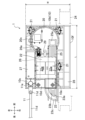
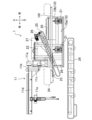
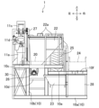
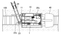
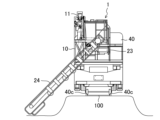
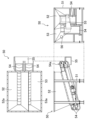
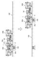
図1、図2、図3に、現場練り製造ユニットの一例を示す(単に製造ユニット1ともいう)。図1は、製造ユニット1を上方から見た図である。図2は、製造ユニット1を右側方から見た図である。図3は、製造ユニット1を後方から見た図である。
<On-site kneading manufacturing unit>
An example of an on-site mixing production unit is shown in Figures 1, 2 and 3 (also simply referred to as production unit 1). Figure 1 is a view of the
この製造ユニット1は、主に、電車等が走行する線路に沿った箇所で行われる軌道工事に適するように構成されている。軌道工事の具体例としては、電柱の建て替え工事がある。線路脇には、電線を架設するために、線路に沿って間隔を隔てて電柱が設置されている。これら電柱の多くは鉄柱である。鉄柱は、腐食によって老朽化するため、定期的に建て替える必要がある。製造ユニット1は、このような軌道工事で行われるコンクリートの打設に使用される。
This
製造ユニット1は、一回で練り上げることができるコンクリートの量が30~300L程度の、バッチ式の製造装置である。1つのコンパクトなユニット台10の上に、現場練りに必要な複数の関連装置を一体に組み込んで構成されている。
The
例えば、製造ユニット1のサイズおよび重量は、中型程度のトラックの荷台に積載して道路の上を運搬可能な範囲で設計されている。また、軌陸車の荷台にも積載して軌道の上も運搬可能な範囲で設計されている。
For example, the size and weight of the
更に、軌道の上方、約5mの高さには、トロリー線(パンタグラフを通して給電する接触電線)がある。軌道工事では、トロリー線との接触を、確実に回避しなければならない。従って、作業可能な高さには制限がある。例えば、軌道工事を行う作業者の頭からトロリー線まで、少なくとも1.5mの距離を確保する必要がある。 Furthermore, about 5m above the track, there are contact wires (contact wires that supply power through the pantograph). When working on the track, contact with the contact wires must be avoided. Therefore, there are limitations on the height at which work can be done. For example, a distance of at least 1.5m must be ensured between the heads of workers working on the track and the contact wires.
コンクリートの製造には、原料水だけでなく、洗浄水等も必要になるため、比較的多くの用水を確保しなければならない。それに対し、用水の確保が困難な現場がある。そのような現場では、給水タンクの容量が小さいと、必要なコンクリートを製造できないおそれがある。従って、多量の用水を給水タンクに貯留できるようにするのが好ましい。 The production of concrete requires not only raw water but also washing water, etc., so a relatively large amount of water must be secured. However, there are some work sites where it is difficult to secure water. At such sites, if the capacity of the water supply tank is small, there is a risk that the required amount of concrete cannot be produced. Therefore, it is preferable to be able to store a large amount of water in the water supply tank.
用水が確保できれば、その他のコンクリート材料、つまりセメントや骨材を、効率的かつ効果的に繰り返し供給できるようにするのが好ましい。そして、練り上げられたコンクリートを、効率的かつ効果的に打設できるようにするのが好ましい。この製造ユニット1では、これらの課題に対して適切に対応できるように工夫されている。
Once water is available, it is preferable to be able to supply other concrete materials, such as cement and aggregates, repeatedly and efficiently. It is also preferable to be able to pour the mixed concrete efficiently and effectively. This
(ユニット台10)
ユニット台10は、床面10a、支持枠10bなどで構成されている。床面10aの形状は、上面視で長方形であり、その短辺の長さWは2m程度、長辺Lの長さは3m程度に設定されている。支持枠10bは、上下方向に延びる複数の支柱枠や、前後方向または左右方向に延びる複数の梁枠などで、略矩形箱形に形成されている。ユニット台10の高さは1m程度である。
(Unit base 10)
The
(コンベア載置台)
ユニット台10には、クレーン台10c、作業用の第1ステップ10d、着座用の第2ステップ10e、コンベア載置台10fなどが設けられている。クレーン台10c、第1ステップ10d、および、第2ステップ10eは、ユニット台10の後側の縁に沿って設けられている。
(Conveyor placement table)
The
クレーン台10cは、強度に優れた台状の部分であり、ユニット台10の左隅部に設置されている。第1ステップ10dは、立ち作業を可能にする足場であり、図3に示すように、クレーン台10cの右側に設置されている。第1ステップ10dは、後述するスクリューフィーダ26の後方に位置している。第1ステップ10dは、高さ制限と作業性とを考慮して、主にセメントの投入作業用に設計されている。
The
第2ステップ10eは、着座を可能にする足場であり、第1ステップ10dの右側に設置されている。第2ステップ10eは、後述する下流側ベルトコンベア25の後方に位置している。第2ステップ10eは、第1ステップ10dよりも高位置に配置されている。
The
コンベア載置台10fは、ユニット台10の一方の側部(右側部)に沿って延びるように設けられている。コンベア載置台10fは、所定幅で前後方向に延びる帯状の載置可能なスペースからなり、後述する上流側ベルトコンベア24を載置して運搬できるように設計されている。
The
(ジブクレーン)
この製造ユニット1は、ジブクレーン11を備える。詳細には、クレーン台10cの上にジブクレーン11が設けられている。
(Jib crane)
The
ジブクレーン11は、図2に示すように、クレーン台10cの上に立てられた支柱11aと、支柱11aの上部に設けられた軸支部11bと、軸支部11bによって上下方向に延びる軸回りに旋回可能に支持された旋回軸11cと、旋回軸11cから水平方向に延出されたジブ11dと、ジブ11dに取り付けられたクレーン11eとを有している。ジブ11dは、所定の角度範囲で旋回可能に構成されている。
As shown in FIG. 2, the
ジブ11dの長さは、約2mであり、上方から見て、反時計回りに旋回させることで、ユニット台10と上下に重なるように設定されている。また、ジブ11dは、軌陸車40に積載した状態で、軌道から約4mの高さに位置するように設定されている。
The length of the
軌道工事では、上述したように、トロリー線との接触を確実に回避しなければならない。従って、上下方向に揺動するクレーンは、実際に使用することは困難である。それに対し、この製造ユニット1では、安全を考慮して所定の高さに設定された、ジブクレーン11が設置されている。ジブクレーン11は水平方向にのみ旋回するので、高さ要求を確実に満たすことができる。従って、安心して軌道工事が行える。
As mentioned above, during track construction work, contact with the contact wires must be reliably avoided. Therefore, it is difficult to actually use a crane that swings up and down. In contrast, this
関連装置は、ミキサー20、ロードセル21、セメントホッパー22、中継ホッパー23、上流側ベルトコンベア24、下流側ベルトコンベア25、スクリューフィーダ26、第1貯水タンク27、第2貯水タンク28、給水装置29、制御装置30などからなる。図2に示すように、上流側ベルトコンベア24は、ユニット台10に対して独立して設けられている。上流側ベルトコンベア24は、運搬時など、通常はユニット台10に載置されていて、軌道工事の時に、作業現場でユニット台10から降ろされる。
The related equipment includes a
上流側ベルトコンベア24および中継ホッパー23を除く、その他の関連装置は、床面10aの上に収まって床面10aの外側にはみ出さないように、ユニット台10に集約して設置されている。床面10aからの高さも約2mを超えないように設置されている。
Except for the
そして、製造ユニット1の総重量(運搬時の重量であり、用水も含む)は、3500kg以下となるように設定されている。その結果、製造ユニット1は、中型程度のトラックや軌陸車の荷台に積載して簡単に運搬でき、乗り降ろしも容易にできるようになっている。
The total weight of the manufacturing unit 1 (weight at the time of transportation, including water) is set to be 3,500 kg or less. As a result, the
(ミキサー)
ミキサー20は、いわゆるパン型のミキサーである。ミキサー20は、内部に撹拌羽根が設置されている底の浅い有底円筒状の捏練容器と、捏練容器の上部を覆う上蓋と、開閉可能な払出口20cとを有している。撹拌羽根は、制御装置30の制御に従って、図示しないモータの駆動によって回転する。なお、使用するコンクリート材料によっては、パン型に代えて、グラウトミキサーを用いてもよい。
(mixer)
The
図1に示すように、払出口20cは、ユニット台10の左側方に配置されている。すなわち、ユニット台10の一方の長辺と対向する部位に払出口20cが配置されている。そして、ミキサー20で練り上げられたコンクリートを、ユニット台10の側方に払い出せるように、払出口20cは、斜め下方に向かって延びるシューターを有している。
As shown in FIG. 1, the
ミキサー20は、ユニット台10の横幅方向(左右方向)の略中央部(僅かに左寄り)に位置し、ユニット台10の長手方向の一方の端部(前端部)に配置されている。上方から見て、ミキサー20は、ユニット台10の横幅の約2/3程度の直径を有している。
The
ミキサー20は、ロードセル21を介してユニット台10に支持されている。ロードセル21は、荷重を電気信号に変換するセンサである。ロードセル21は、ミキサー20の重量変化を計測する。ロードセル21は、制御装置30と電気的に接続されており、計測した値を制御装置30に出力する。
The
(セメントホッパー、スクリューフィーダ)
セメントホッパー22は、上部に矩形の大きな投入口を有し、下部に小さなセメント排出口を有する箱形容器である。セメントホッパー22は、図3に示すように、前後方向から見て、略直角三角形状を有し、その斜辺が右斜め下方に臨むように配置されている。
(Cement hopper, screw feeder)
The
投入口には、一対の扉22a,22aを有する蓋が取り付けられている。これら一対の扉22a,22aは、左右方向に揺動して開閉する(いわゆる観音開き)。排出口は、セメントホッパー22の尖った下端部に配置されている。セメントホッパー22は、ユニット台10の横幅方向の略中央部に位置し、ミキサー20に隣接した状態でユニット台10の後端部の側に配置されている。
A lid having a pair of
セメントホッパー22には、投入口を通じて、セメントが投入される。セメントホッパー22に投入されたセメントは、スクリューフィーダ26が搬送することによってミキサー20に投入される。
Cement is added to the
スクリューフィーダ26は、図2に示すように、内部にスクリュー軸が設けられた円柱状の公知の装置である。スクリュー軸の回転によってセメントを移送する。スクリューフィーダ26は、ユニット台10の長辺に沿って延びている。セメントホッパー22の排出口の下方に、スクリューフィーダ26の後端部が配置されている。ミキサー20の上部にスクリューフィーダ26の前端部が配置されている。
As shown in FIG. 2, the
スクリューフィーダ26は、後端部から前端部に向かって上り傾斜している。スクリューフィーダ26の前端部は、捏練容器20aの内部に連通しているフィーダダクト26aに収容されている。スクリューフィーダ26は、フィーダダクト26aを通じて、セメントを捏練容器20aの内部に供給する。
The
(中継ホッパー、下流側ベルトコンベア)
中継ホッパー23には、骨材が投入される。下流側ベルトコンベア25は、その骨材を搬送してミキサー20に供給する。骨材は、配合割合の多いコンクリート材料であり、その主体は、一般に、砂(細骨材)と、砂よりも粒度の大きい砕石や砂利(粗骨材)とで構成されている。細骨材および粗骨材は、いずれも骨材ではあるが、コンクリート材料としては、別々の原料として扱われる。
(Relay hopper, downstream belt conveyor)
Aggregate is fed into the
図1に示すように、中継ホッパー23は、ユニット台10の後端部に配置されている。詳細には、中継ホッパー23は、第2ステップ10eから後方に張り出すように設置されている。中継ホッパー23は、上方から見て、扇形(円形の四分の一の形状)に形成されている。中継ホッパー23は、その上部に扇形の投入口23aを有し、その下部に骨材排出口23bを有している。中継ホッパー23は、その円弧状の縁23cが、ミキサー20の払出口20cと同じように、左側に向くように配置されている。
As shown in FIG. 1, the
下流側ベルトコンベア25は、スクリューフィーダ26の右側に配置されている。下流側ベルトコンベア25は、セメントホッパー22の下方を通り、スクリューフィーダ26に沿って前後方向に延びている。下流側ベルトコンベア25は、後端部から前端部に向かって上り傾斜している。
The
下流側ベルトコンベア25の後端部は、中継ホッパー23の骨材排出口23bの下方に配置されている。下流側ベルトコンベア25の前端部は、ミキサー20の内部に連通しているコンベアダクト25aに収容されている。下流側ベルトコンベア25は、コンベアダクト25aを通じて、ミキサー20の内部に骨材を供給する。
The rear end of the
(第1貯水タンク、第2貯水タンク)
この製造ユニット1では、多量の用水を貯留できるように、貯水タンクが2つ設置されている。具体的には、各装置の配置を工夫することによって、ユニット台10に空きスペースを確保し、その空きスペースに第1貯水タンク27と第2貯水タンク28とが設置されている。
(First water tank, second water tank)
Two water tanks are installed in this
第1貯水タンク27は、支持枠10bの上に設置された縦長な矩形箱型のタンクであり、クレーン台10cの前側かつセメントホッパー22の左側であって、ユニット台10の左側部に沿った位置に配置されている。第2貯水タンク28は、第1貯水タンク27よりも容量の小さい矩形箱型のタンクからなり、床面10aの上に設置されている。第2貯水タンク28は、ユニット台10の後端部の右隅部に配置されている。
The first
これら第1貯水タンク27および第2貯水タンク28の双方には、少なくとも500L以上の用水を貯留できるように設計されている。例えば、約700Lの用水があれば、原料水や洗浄水を現場で確保ができなくても、約4t(2m3)のコンクリートを製造できる。また、製造ユニット1を運送可能にすることを考慮すると、700L以下が好ましい。
Both the first
(給水装置)
図1に給水装置29を示す。給水装置29は、詳細は図示しないが、ポンプ、配管、電磁開閉弁、流量計などで構成されている。給水装置29は、制御装置30からの指示に従ってポンプや電磁開閉弁を作動させる。それにより、給水装置29は、第1貯水タンク27または第2貯水タンク28に貯留する用水の所定量をミキサー20に供給する。
(Water supply equipment)
1 shows the
(上流側ベルトコンベア)
上流側ベルトコンベア24は、長さが約5mのベルトコンベアである。上流側ベルトコンベア24は、ユニット台10に対して移設可能であり、ユニット台10とは別に設けられている。
(Upstream conveyor belt)
The upstream
すなわち、上述したように、上流側ベルトコンベア24は、運搬時等、通常の状態では、コンベア載置台10fに載置されている(運搬可能状態)。そして、コンクリートの製造時は、上流側ベルトコンベア24は、ジブクレーン11により、骨材を搬送して中継ホッパー23に投入する状態(使用可能状態)に移設される。
That is, as described above, the
(制御装置30)
制御装置30は、図3に示すように、クレーン台10cの下方の床面10aの上に設置されている。制御装置30は、コンピュータや、コンピュータに実装された各種ソフトウエアなどで構成されており、コンクリートを製造するための制御を実行する。制御装置30にはまた、製造条件等の表示が可能なモニターや、製造条件等の入力が可能な入力装置、製造条件等の印刷が可能な出力装置なども備えられている。
(Control device 30)
The
制御装置30は、ロードセル21の計測値に基づいて、ミキサー20、スクリューフィーダ26、下流側ベルトコンベア25、および、給水装置29の作動を制御する。すなわち、制御装置30は、下流側ベルトコンベア25およびスクリューフィーダ26の作動タイミング、給水タイミング、ミキサー20の作動時間など、製造に関連する制御を実行する。
The
例えば、セメント、細骨材、粗骨材、および、原料水等からなる各コンクリート材料が、ミキサー20に連続して供給される。制御装置30は、これらコンクリート材料毎に、計測をリセットして自動的に供給量を計測する。
For example, concrete materials consisting of cement, fine aggregate, coarse aggregate, raw water, etc. are continuously supplied to the
その際、セメントなど、粉粒体のコンクリート材料は、ミキサー20の内部で山積み状態になり、ミキサー20の外に漏れ出すおそれがある。制御装置30は、計量の途中で、ミキサー20を一定時間作動し、ミキサー20の内部のコンクリート材料を略平らに均す処理を実行する(均し処理)。それにより、より多くのコンクリート材料をミキサー20に収容できるので、コンクリートの製造量が増大する。配合比の差が激しい偏った設定値でのコンクリートの製造にも適切に対応できるので、コンクリートの品質が向上する。
During this process, powdered concrete materials such as cement may pile up inside the
上流側ベルトコンベア24は、コンクリートの製造を自動化する上では、制御装置30でその作動を制御するのが好ましいが、制御装置30から独立して作動させてもよい(説明では独立して作動させるものとする)。
In order to automate the production of concrete, it is preferable to control the operation of the
制御装置30は、ミキサー20で練り上げる1バッチ分のコンクリートの製造量に応じて、セメント、原料水、細骨材、および、粗骨材の各々のミキサー20への供給量を得る処理(供給量演算処理)を実行する。そして、供給量演算処理で得られた供給量となるように、ミキサー20、スクリューフィーダ26、下流側ベルトコンベア25、および、給水装置29の作動を制御する処理(作動制御処理)を実行する。
The
この製造ユニット1の場合、細骨材および粗骨材は、同じ上流側ベルトコンベア24および下流側ベルトコンベア25を用いて、ミキサー20に連続的に供給される。例えば、細骨材が先に上流側ベルトコンベア24および下流側ベルトコンベア25によってミキサー20に供給された場合、その後、続けて粗骨材が上流側ベルトコンベア24および下流側ベルトコンベア25によってミキサー20に供給される。
In the case of this
先に供給された細骨材は、所定量に達すると、下流側ベルトコンベア25の作動が停止され、ブザーやランプで報知される。報知により、作業者は、上流側ベルトコンベア24の作動も停止する。そして、続けて粗骨材の投入が行われる。ところが、そのとき、上流側ベルトコンベア24および下流側ベルトコンベア25の上には、細骨材が残存している。従って、これらもミキサー20に供給される。
When the amount of fine aggregate supplied earlier reaches a predetermined amount, the operation of the
そこで、この製造ユニット1では、作動制御処理において補正処理が実行される。すなわち、先に投入された細骨材については、演算して得られた供給量から、下流側ベルトコンベア25および上流側ベルトコンベア24の双方に残る細骨材の量(コンベア残存量)を減算した量が供給されるように、制御装置30は、下流側ベルトコンベア25の作動を制御する。詳細には、ロードセル21の計量値を補正する。なお、コンベア残存量は、予め実験等によって求められ、制御装置30に記憶されている。コンベア残存量は、作業者が入力してもよい。
Therefore, in this
換言すれば、供給量演算処理で得られた供給量よりも、コンベア残存量の分だけ少ないタイミングで、下流側ベルトコンベア25の作動が停止され、ブザーやランプでの報知により、上流側ベルトコンベア24の作動も停止される。そして、続けて粗骨材の投入が行われることで、コンベア残存量がミキサー20に供給される。その結果、適量の細骨材がミキサー20に供給される。
In other words, the operation of the
後に投入される粗骨材は、補正されたロードセル21の計量値により、所定量に達すると、下流側ベルトコンベア25の作動が停止され、ブザーやランプで報知される。その結果、適量の粗骨材がミキサー20に供給される。細骨材と粗骨材の投入順が逆の場合でも扱いは同じである。
When the amount of coarse aggregate added later reaches a predetermined amount based on the corrected weight value of the
細骨材および粗骨材を、同じ上流側ベルトコンベア24および下流側ベルトコンベア25を用いて、ミキサー20に連続的に供給しても、精度高く計量できる。高品質なコンクリートを製造できる。なお、上流側ベルトコンベア24を使用しないで、中継ホッパー23から骨材を投入する場合も考えられる。その場合、下流側ベルトコンベア25に残る骨材の量をコンベア残存量とすればよい。
Even if fine aggregate and coarse aggregate are continuously supplied to the
更に、制御装置30は、ミキサー20でコンクリートを練り上げる時に、スランプ値を計測してモニターに表示するスランプ値計測処理が実行可能構成されている。通常、コンクリートを打設する前には、製造されたコンクリートの品質を確認するために、製造されたコンクリートを用いて、スランプ値(コンクリートの流動性に関する指標)を求めるスランプ試験が行われる。ところが、現場によっては、スランプ試験を行うのが困難な場合がある。
Furthermore, the
それに対し、制御装置30は、スランプ値計測処理の実行により、ミキサー20でコンクリートを練り上げる時にモータに加わる負荷トルクを利用して、スランプ値を計測し、その値をモニターに表示する。従って、別途スランプ試験を行う必要がないので、作業の時間および労力が低減できる。製造中にスランプ値の調整が可能になるので、適切なスランプ値のコンクリートを安定して製造できる。
In response to this, the
具体的には、制御装置30には、ミキサー20での練り混ぜ量(コンクリート材料および水の総重量)に応じて、モータに加わる負荷トルクからスランプ値を算出することが可能になるデータ(スランプ値換算データ)が、予め行った実験結果等に基づいて、記憶されている。
Specifically, the
制御装置30は、コンクリートを練り上げている時にモータへ出力される電流値と、ロードセル21の計測値に基づいて得られるキサーでの練り混ぜ量と、スランプ値換算データとを用いて、スランプ値を実測する。そうして得られるスランプ値をモニターに表示する。従って、実測されるスランプ値が、求めるスランプ値と差がある場合には、練り上げ中に、製造後のスランプ値を調整できる。
The
(コンクリートの製造)
例えば、作業者は、第1ステップ10dの上に立ち、手作業で、セメントホッパー22にセメントを投入する。このとき、セメントホッパー22の投入口の一方の扉22aは、セメント袋の載置台として利用できる。扉22aを全開にすれば、コンテナバック等を用いた機械作業による投入も容易にできる。
(Concrete production)
For example, a worker stands on the
作業者はまた、手作業で、細骨材および粗骨材を、中継ホッパー23に投入する。直接中継ホッパー23に投入してもよいし、上流側ベルトコンベア24を用いて投入してもよい。そうして、作業者は制御装置30を操作する。
The worker also manually loads the fine aggregate and coarse aggregate into the
それにより、制御装置30は、セメント、細骨材、および、粗骨材の1バッチ分の所定量をミキサー20に供給する。更に、給水装置29を作動させ、ミキサー20に1バッチ分の原料水を給水する。そうして、制御装置30は、ミキサー20を作動させることにより、所定時間、撹拌羽根を回転させて、コンクリートを練り上げる。練り上げられたコンクリートは、払出口20cから払い出す。
The
<現場練り製造ユニットによる軌道工事>
上述したように、この製造ユニット1は、軌道工事向けに、軌陸車の荷台に積載した状態で、効率的かつ効果的に使用できるように構成されている。
<Railway construction using on-site mixing manufacturing units>
As described above, the
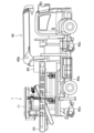
図4に、軌陸車40に製造ユニット1を積載した状態を示す。軌陸車40は、道路および軌道の両方の走行が可能な公知の車両であり、様々なタイプが実用化されている。例示の軌陸車40には、荷台40aとクレーン40bが備えられている。
Figure 4 shows the state in which the
軌陸車40の車体には、道路走行用の車輪に加え、軌道走行用の鉄輪40cが昇降可能に組み付けられている。軌陸車40は、踏切などから線路内に入り込み、軌道に合わせて鉄輪40cを降下させることにより、軌道上を走行できるようになる。
The body of the road-
製造ユニット1は、その後端部を後側に向けた状態で、発電機60と共に、軌陸車40の荷台40aに載置される。上流側ベルトコンベア24は、コンベア載置台10fに載置されている。上流側ベルトコンベア24の前端部分および後端部分は、ユニット台10から突出しているが、荷台40aへの積載および運搬に支障はないように設計されている。
The
この軌陸車40には、クレーン40bが備えられているので、大容量のコンテナバックを用いて、セメントホッパー22へのセメントの投入は容易かつ確実にできる。従って、軌道工事の前に、作業現場とは異なる場所で、十分量のセメントをセメントホッパー22に収容しておくのが好ましい。なお、トロリー線と接触する可能性があるため、このクレーン40bを軌道上で使用することは難しい。
This road-
細骨材および粗骨材は、予め、作業現場の軌道の際に準備しておき、作業現場で、作業者によって投入される。第1貯水タンク27および第2貯水タンク28に貯留した用水を用いて、バッチ式のコンクリートの製造を連続的に行うことにより、コンクリートを打設する。そのような軌道工事方法の一例について説明する。
The fine and coarse aggregates are prepared in advance at the work site when the track is laid, and are added by workers at the work site. The concrete is poured by continuously producing batch-type concrete using water stored in the
図5の上図に、電車が走行する軌道100とその周辺部分を示す。軌道100の横には、電線を架設するために、電柱101(鉄柱)が設置されている。電柱101の下部101aは、コンクリートで固められた状態で地中に埋設されている。
The upper diagram in Figure 5 shows a
例えば、老朽化した電柱101を建て替えるために、その電柱101に隣接した位置に新たな電柱101を設置する場合を想定する。
For example, consider a case in which a
その場合、まず、図5の下図に示すように、新たな電柱101の設置部位に、直径が0.5~1.5mで深さが2~5mの縦穴102を掘削する。そして、その中に、基礎となるコンクリートの枠材103を設置し、その枠材103に電柱101の下部101aを組み付ける。そうして、縦穴102にコンクリートを打設し、硬化させる。コンクリートが硬化した後、電柱101の下部101aにその上部を組み付ける。
In this case, first, as shown in the lower diagram of Figure 5, a
これら作業のうち、特に、コンクリートを打設する作業が、時間および労力を要する。そのうえ、深夜の短期間で確実に完了させる必要があるため、負担が大きい。それに対し、この製造ユニット1であれば、軌陸車40に搭載した状態で、効率的かつ効果的にコンクリートを打設することができる。
Of these tasks, pouring concrete in particular is time-consuming and labor-intensive. Moreover, it is a heavy burden to complete the task reliably in a short period of time, even late at night. In contrast, with this
すなわち、製造ユニット1を軌陸車40で作業現場に搬送し、払出口20cが、軌道100の横に隣接する打設部位、つまり縦穴102と対向するように、ユニット台10を配置する(位置決めステップ)。製造ユニット1は、軌陸車40に搭載してあるので、軌陸車40で軌道100上を走行することにより、作業現場に簡単かつ短時間で移動でき、最適な位置に配置できる。
That is, the
次に、作業者は、ジブクレーン11を操作し、コンベア載置台10fに載置されている上流側ベルトコンベア24を、骨材を搬送して中継ホッパー23に投入することができる状態(使用可能状態)に移設する。
Next, the worker operates the
すなわち、ジブクレーン11に上流側ベルトコンベア24を吊して、ジブ11dを旋回させる。ジブ11dは、水平方向にしか旋回しないので、トロリー線に接触するおそれはない。そして、上流側ベルトコンベア24の上流側の端部(上流端部)を、打設部位と同じ側の、軌道100の横に配置し、その下流側の端部(下流端部)を中継ホッパー23の上部に配置する(設置ステップ)。
That is, the
例えば、図6A、図6Bに示すように、ユニット台10に対して、上流側ベルトコンベア24が、左斜め後方に傾斜するように配置する。中継ホッパー23は、扇形の投入口23aを有しているので、下流端部は、その円弧状の縁23cに載置できる。すなわち、上流側ベルトコンベア24は、ユニット台10に対して、後方に向く位置から左側に向く位置までの範囲であれば、任意の角度で配置できる。
For example, as shown in Figures 6A and 6B, the
上述したように、細骨材および粗骨材は予め、作業現場に準備しておき、上流端部がその近傍に位置するように配置すればよい。このとき、盛り土により、軌道100は、その横の領域よりも高くなっている場合があるが、上流側ベルトコンベア24は、5mの長さがあるので、その設置位置や傾斜角度を調整することで、適切な状態に移設できる。
As mentioned above, the fine aggregate and coarse aggregate are prepared in advance at the work site, and the upstream end is positioned nearby. At this time, the
そうして、作業者が制御装置30を操作すると、制御装置30は、上述したように、セメントをミキサー20に所定量供給する。作業現場でセメントをセメントホッパー22に投入する場合には、一人の作業者が第1ステップ10dの上に立って作業する。そうすれば、高さ制限の範囲内で、セメントホッパー22に対して適度な高さになるように設計されている。従って、効率よくセメントを投入する作業ができる。
When the worker operates the
作業者は、細骨材および粗骨材のうちの一方の骨材を、上流側ベルトコンベア24を用いて、中継ホッパー23に投入する。所定量(コンベア残存量を減算した量)に達すると、下流側ベルトコンベア25が停止し、ブザーやランプで報知されるので、作業者は、上流側ベルトコンベア24を停止する。
The worker loads either the fine aggregate or the coarse aggregate into the
作業者は、続いて、他方の骨材を、上流側ベルトコンベア24を用いて中継ホッパー23に投入する。所定量に達すると、下流側ベルトコンベア25が停止し、ブザーやランプで報知されるので、作業者は、上流側ベルトコンベア24を停止する。そうすると、制御装置30は、給水装置29で原料水を所定量給水し、その後、ミキサー20でコンクリートを練り上げる(製造ステップ)。
The worker then loads the other aggregate into the
その後、ミキサー20で製造されたコンクリートを払出口20cから払い出し、縦穴102に流し込む(打設ステップ)。このとき、払出口20cは、ユニット台10の側方に位置しており、縦穴102に向けて最短距離で払い出すことができる。例えば、高低差を利用して、シューターと縦穴102との間に、後述する樋状の部材Sを掛け渡せば、コンクリートを軌道100上にこぼすことなく、容易かつ短時間で、コンクリートを縦穴102に流し込むことができる。
Then, the concrete produced by the
1バッチ分のコンクリートの製造が終われば、続けて次のバッチの製造を開始することができる。作業現場で用水の確保ができなくても、第1貯水タンク27および第2貯水タンク28に多量の用水を貯留しているので、少なくとも約4tのコンクリートを製造できる。
Once one batch of concrete has been produced, the next batch can be started immediately. Even if water cannot be secured at the work site, at least about 4 tons of concrete can be produced because a large amount of water is stored in the
従って、多量のコンクリートが必要な現場にも対応できるし、工事箇所が複数の現場にも対応できる。 Therefore, it can be used at sites where large amounts of concrete are required, and at sites with multiple construction sites.
<現場練り製造ユニットの応用例>
上述した上流側ベルトコンベア24を用いた方法では、作業者が1バッチごとに、細骨材および粗骨材を投入しなければならない。従って、時間および労力の負担が大きい。また、電柱101の建て替え工事などでは、複数箇所の作業現場を移動しながら、連続してコンクリートを打設するのが一般的である。そのため、手作業は少ない方が、工期を短縮できるので好ましい。
<Application example of on-site kneading manufacturing unit>
In the method using the
そこで、応用例の現場練り製造ユニット1では、そのような連続したコンクリートの打設作業が、より効率的かつ効果的に行えるよう、更に、製造ユニット1と共用される補助ユニット50が備えられている。
Therefore, in the application example of the on-site
図7に、補助ユニット50を例示する。補助ユニット50は、フレーム枠51、第1骨材ホッパー52、第2骨材ホッパー53、一対の骨材用ベルトコンベア54,54などで構成されている。
Figure 7 shows an example of the
フレーム枠51は、トラックおよび軌陸車の各々の荷台に積載して運搬可能なサイズに形成された枠部材である。フレーム枠51に、第1骨材ホッパー52、第2骨材ホッパー53、および一対の骨材用ベルトコンベア54,54が支持されている。第1骨材ホッパー52および第2骨材ホッパー53の各々は、上面が開口した矩形箱形の容器である。
The
第1骨材ホッパー52および第2骨材ホッパー53は、互いに隣接した状態で一体に構成されている。第1骨材ホッパー52および第2骨材ホッパー53の各々の下部は窄まっており、それらの下端部の各々に骨材排出口52a,53aが形成されている。例えば、第1骨材ホッパー52には粗骨材が投入され、第2骨材ホッパー53には細骨材が投入される。
The first
各骨材用ベルトコンベア54は、第1骨材ホッパー52および第2骨材ホッパー53の各々の下方に設置されている。各骨材用ベルトコンベア54は、第1骨材ホッパー52および第2骨材ホッパー53の各々の骨材排出口52a,53aの下方に沿って延びており、それらの上側に位置する一方(前方)の端部(排出端部54a)は、フレーム枠51から突出している。これら骨材用ベルトコンベア54は、互いに平行して傾斜した状態で、フレーム枠51に支持されている。
Each
これら骨材用ベルトコンベア54,54は、第1骨材ホッパー52および第2骨材ホッパー53の各々に投入された細骨材および粗骨材の各々を同時に搬送し、これら骨材を同じ中継ホッパー23に投入する。そのため、これら骨材用ベルトコンベア54,54は、各々の排出端部54aが近接するように、上下方向に位置をずらした状態で配置されている。
These
更に、これら排出端部54a,54aの下方には、骨材を安定して中継ホッパー23に投入できるように、骨材を中継ホッパー23の投入口23aに導く投入ガイド55が設置されている。細骨材が投入される第2骨材ホッパー53には、内部に細骨材が残らないように、バイブレータ56が取り付けられている。
Furthermore, below these discharge ends 54a, 54a, a
これら排出端部54a,54aは、製造ユニット1に向けて、補助ユニット50を軌道上で移動させた場合に、中継ホッパー23の投入口23aの上方に位置する高さに設置されている。従って、図8に示すように、軌道100の上で、製造ユニット1を搭載した軌陸車40(製造車A)に、補助ユニット50を搭載した軌陸車40(補助車B)を隣接させることで、排出端部54aが中継ホッパー23の投入口23aの上方に位置するように、製造ユニット1と補助ユニット50とを連結することができる。
These discharge ends 54a, 54a are installed at a height that is above the
各骨材用ベルトコンベア54が作動すると、第1骨材ホッパー52および第2骨材ホッパー53の各々に受け入れた細骨材および粗骨材は、これら骨材用ベルトコンベア54,54によって搬送され、中継ホッパー23に投入される。従って、補助ユニット50に収容した細骨材および粗骨材の各々を第1骨材ホッパー52および第2骨材ホッパー53の各々に投入すれば、機械的に、多量の細骨材および粗骨材を連続して供給できる。
When each
細骨材および粗骨材が不足すれば、補助車Bを、製造ユニット1から切り離して移動させ、細骨材および粗骨材を第1骨材ホッパー52および第2骨材ホッパー53の各々に補充することができる。製造車Aでの作業を止めることなく、細骨材および粗骨材を連続して供給することが可能になる。
If there is a shortage of fine aggregate and coarse aggregate, the auxiliary vehicle B can be detached from the
従って、この応用例の現場練り製造ユニット1によれば、効率的かつ効果的に、複数箇所で連続的に軌道工事が行える。例えば、図8の上図に示すように、製造車Aを、第1の現場での打設部位(縦穴102)に対して位置決めするとともに、補助車Bを、補助ユニット50が製造ユニット1と連結されるように位置決めする(位置決めステップ、設置ステップ)。
Therefore, with the on-site
そうして、ミキサー20に、縦穴102に必要とされる所定量のセメント、細骨材、粗骨材、および、原料水を投入し、所定時間、ミキサー20を作動させることによってコンクリートを練り上げる(製造ステップ)。この間、細骨材または粗骨材が不足すれば、補助車Bを移動させ、投入作業が容易な場所で、細骨材または粗骨材を補充すればよい。
Then, the
コンクリートが練り上がれば、払出口20cを開いて、製造されたコンクリートを払い出す。そのコンクリートを、シューターや樋状の部材Sを用いて縦穴102に流し込む(打設ステップ)。それにより、第1の現場での作業は終了である。
Once the concrete is mixed, the
続いて、図8の下図に示すように、製造車Aおよび補助車Bを移動させ、製造車Aおよび補助車Bを、第2の現場の縦穴102に合わせて位置決めする。そして、第1の現場と同様に、コンクリートの打設を行う。このような作業を連続して繰り返すことで、複数箇所での電柱101の建て替えを効率的かつ効果的に行うことができる。
Next, as shown in the lower diagram of Figure 8, manufacturing vehicle A and auxiliary vehicle B are moved and positioned to align with the
第1貯水タンク27および第2貯水タンク28に多量の用水を確保しているので、水の確保が難しい作業現場でも、連続してコンクリートの製造が行える。
Since a large amount of water is stored in the first
短時間で、高品質な工事が行えるので、夜間の限られた時間でも多くの工事を完了できる。軌道を走行するので、軌道の外側からアクセスできない現場でも行える。高さを要する作業も、電線の無い箇所で行えばよいので、作業の制約を受けることもない。 Since it can carry out high-quality work in a short amount of time, a lot of work can be completed even during limited hours at night. Because it runs on tracks, it can be used at sites that cannot be accessed from outside the tracks. Work that requires height can be done in places where there are no power lines, so there are no restrictions on work.
従って、このような現場練り製造ユニット1によれば、軌道工事の遅滞を解消できる。
Therefore, this on-site
なお、開示する技術にかかる軌道工事向けの現場練り製造ユニットは、上述した実施形態に限定されず、それ以外の種々の構成をも包含する。例えば、製造ユニット1、補助ユニット50などの構成は、一例であり、仕様に応じて適宜変更できる。製造ユニット1や補助ユニット50の道路上の輸送は通常のトラックで行い、軌道上の移動は、コンテナ車等に載せ替えて行ってもよい。
The on-site mixing manufacturing unit for track construction according to the disclosed technology is not limited to the above-mentioned embodiment, but also includes various other configurations. For example, the configurations of the
1 現場練り製造ユニット
10 ユニット台
10f コンベア載置台
11 ジブクレーン
20 ミキサー
21 ロードセル
22 セメントホッパー
23 中継ホッパー
24 上流側ベルトコンベア
25 下流側ベルトコンベア
26 スクリューフィーダ
27 第1貯水タンク
28 第2貯水タンク
29 給水装置
30 制御装置
40 軌陸車(トラック)
50 補助ユニット
1 On-site
50 Auxiliary Unit
Claims (7)
トラックの荷台に積載可能、かつ、道路および軌道の上を運搬可能な、上面視が前後に長い長方形をしたユニット台と、
前記ユニット台の上に一体に組み込まれる複数の関連装置と、
を備え、
前記関連装置は、
前記ユニット台の前端部に配置されて、コンクリートを練り上げるミキサーと、
前記ミキサーの重量変化を計測するロードセルと、
前記ユニット台の後端部の側で前記ミキサーと隣接し、セメントが投入されるセメントホッパーと、
前記セメントホッパーに投入されたセメントを搬送して前記ミキサーに供給するスクリューフィーダと、
前記ユニット台の後端部に配置されて、骨材が投入される中継ホッパーと、
前記中継ホッパーに投入された骨材を搬送して前記ミキサーに供給する下流側ベルトコンベアと、
骨材を搬送して前記中継ホッパーに投入する上流側ベルトコンベアと、
コンクリートの製造に用いる用水を貯留する貯水タンクと、
前記貯水タンクから前記ミキサーに用水を供給する給水装置と、
前記ロードセルの計測値に基づいて、前記ミキサー、前記スクリューフィーダ、前記下流側ベルトコンベア、および、前記給水装置の作動を制御する制御装置と、
を含み、
前記上流側ベルトコンベアが、前記ユニット台に対して移設可能に設けられると共に、前記上流側ベルトコンベアを載置して運搬可能にするためのコンベア載置台が、前記ユニット台の一方の側部に沿って延びるように設けられている、現場練り製造ユニット。 A site-mixed concrete manufacturing unit for track construction, comprising:
A unit base that can be loaded onto a truck bed and transported on roads and tracks and has a rectangular shape long from front to back when viewed from above;
A plurality of related devices are integrally assembled on the unit base;
Equipped with
The related device is
A mixer disposed at a front end of the unit table for mixing concrete;
A load cell for measuring a change in weight of the mixer;
a cement hopper adjacent to the mixer at the rear end of the unit table and into which cement is introduced;
A screw feeder that conveys the cement charged in the cement hopper and supplies it to the mixer;
A relay hopper disposed at a rear end of the unit table and into which aggregate is input;
a downstream belt conveyor that conveys the aggregate charged in the relay hopper and supplies it to the mixer;
an upstream belt conveyor that conveys aggregate and deposits it into the relay hopper;
A water tank for storing water used in the production of concrete;
a water supply device for supplying water from the water storage tank to the mixer;
a control device that controls the operation of the mixer, the screw feeder, the downstream belt conveyor, and the water supply device based on the measurement value of the load cell;
Including,
An on-site mixing production unit, in which the upstream belt conveyor is movable relative to the unit table, and a conveyor mounting table for placing the upstream belt conveyor on and transporting it is provided extending along one side of the unit table.
前記ユニット台の上に、所定の高さ以下に設置されたジブクレーンを更に備え、
前記上流側ベルトコンベアが、前記ジブクレーンにより、前記コンベア載置台に載置される運搬可能状態と、骨材を搬送して前記中継ホッパーに投入する使用可能状態との間で移設される、現場練り製造ユニット。 In the on-site mixing production unit according to claim 1,
Further, a jib crane is installed on the unit base at a predetermined height or lower,
An on-site mixing production unit in which the upstream belt conveyor is moved by the jib crane between a transportable state in which it is placed on the conveyor platform and a usable state in which it transports aggregate and deposits it into the relay hopper.
骨材は、前記上流側ベルトコンベアおよび前記下流側ベルトコンベアによって前記ミキサーに連続的に供給される細骨材および粗骨材を含み、
前記制御装置が、
前記ミキサーで練り上げるコンクリートの製造量に応じて、セメント、用水、細骨材、および、粗骨材の各々の前記ミキサーへの供給量を得る供給量演算処理と、
前記供給量演算処理で得られた供給量となるように、前記ミキサー、前記スクリューフィーダ、前記下流側ベルトコンベア、および、前記給水装置の作動を制御する作動制御処理と、
を実行し、
細骨材および粗骨材のうち、先に投入された骨材については、演算して得られた供給量から、少なくとも前記下流側ベルトコンベアの残存量を減算した量が供給されるように、少なくとも前記下流側ベルトコンベアの作動を制御する、現場練り製造ユニット。 In the on-site kneading production unit according to claim 1 or 2,
The aggregate includes fine aggregate and coarse aggregate continuously supplied to the mixer by the upstream belt conveyor and the downstream belt conveyor,
The control device,
A supply amount calculation process for obtaining the supply amount of each of cement, water, fine aggregate, and coarse aggregate to the mixer according to the production amount of concrete to be mixed by the mixer;
an operation control process for controlling the operations of the mixer, the screw feeder, the downstream belt conveyor, and the water supply device so as to achieve the supply amount obtained by the supply amount calculation process;
Run
An on-site mixing production unit that controls the operation of at least the downstream belt conveyor so that, for the fine aggregate and coarse aggregate that are added first, the amount supplied is equal to at least the remaining amount on the downstream belt conveyor subtracted from the calculated supply amount.
前記現場練り製造ユニットと共用される補助ユニットを更に備え、
前記補助ユニットは、
トラックの荷台に積載可能、かつ、道路および軌道の上を運搬可能なフレーム枠と、
前記フレーム枠に支持されて、細骨材および粗骨材の各々が投入される第1骨材ホッパーおよび第2骨材ホッパーと、
前記第1骨材ホッパーおよび前記第2骨材ホッパーの各々に投入された細骨材および粗骨材の各々を搬送する一対の骨材用ベルトコンベアと、
を有し、
前記一対の骨材用ベルトコンベアが、上下方向に位置をずらして平行した状態で近接配置されている、現場練り製造ユニット。 In the on-site kneading production unit according to claim 3,
Further comprising an auxiliary unit shared with the on-site kneading manufacturing unit,
The auxiliary unit includes:
A frame that can be loaded onto a truck bed and transported on roads and tracks;
a first aggregate hopper and a second aggregate hopper supported by the frame and into which fine aggregate and coarse aggregate are respectively introduced;
a pair of aggregate belt conveyors for transporting the fine aggregate and the coarse aggregate charged into the first aggregate hopper and the second aggregate hopper, respectively;
having
The pair of aggregate belt conveyors are arranged close to each other in parallel with a vertical offset in position, forming an on-site mixing production unit.
請求項1~3のいずれかに記載されている前記現場練り製造ユニットを、軌陸車で作業現場に搬送し、軌道の横に隣接する打設部位と対向するように、前記ユニット台を配置する位置決めステップと、
前記コンベア載置台に載置されている前記上流側ベルトコンベアを移動させ、その上流側の端部を前記軌道の横に配置すると共に、その下流側の端部を前記中継ホッパーの上部に配置する設置ステップと、
前記セメントホッパーを用いて、セメントを前記ミキサーに所定量供給し、かつ、前記上流側ベルトコンベア、前記中継ホッパー、および、前記下流側ベルトコンベアを用いて骨材を前記ミキサーに所定量供給し、かつ、前記給水装置で用水を所定量給水した後、前記ミキサーでコンクリートを練り上げる製造ステップと、
製造されたコンクリートを前記ミキサーから払い出して、前記打設部位に流し込む打設ステップと、
を含む、軌道工事方法。 A track construction method comprising the steps of:
A positioning step of transporting the on-site mixing manufacturing unit according to any one of claims 1 to 3 to a work site by a railroad car and positioning the unit table so as to face the adjacent pouring site next to the track;
an installation step of moving the upstream belt conveyor placed on the conveyor placement table to place an upstream end of the upstream belt conveyor beside the track and a downstream end of the upstream belt conveyor above the relay hopper;
a manufacturing step of supplying a predetermined amount of cement to the mixer using the cement hopper, supplying a predetermined amount of aggregate to the mixer using the upstream belt conveyor, the relay hopper, and the downstream belt conveyor, supplying a predetermined amount of water using the water supply device, and then kneading concrete in the mixer;
A casting step of discharging the produced concrete from the mixer and pouring it into the casting site;
A track construction method comprising:
請求項4に記載されている前記現場練り製造ユニットおよび前記補助ユニットの各々を、軌陸車で作業現場に搬送し、軌道の横に隣接する打設部位と対向するように、前記ユニット台を配置する位置決めステップと、
前記一対の骨材用ベルトコンベアの各々の端部が前記中継ホッパーの上部に位置するように、前記補助ユニットを配置する設置ステップと、
前記セメントホッパーを用いて、セメントを前記ミキサーに所定量供給し、かつ、前記補助ユニット、前記中継ホッパー、および、前記下流側ベルトコンベアを用いて骨材を前記ミキサーに所定量供給し、かつ、前記給水装置で用水を所定量給水した後、前記ミキサーでコンクリートを練り上げる製造ステップと、
製造されたコンクリートを前記ミキサーから払い出して、前記打設部位に流し込む打設ステップと、
を含む、軌道工事方法。 A track construction method comprising the steps of:
A positioning step of transporting each of the on-site mixing production unit and the auxiliary unit described in claim 4 to a work site by a rail-road car and arranging the unit table so as to face the adjacent pouring site next to the track;
an installation step of disposing the auxiliary unit so that each end of the pair of aggregate belt conveyors is located above the relay hopper;
a manufacturing step of supplying a predetermined amount of cement to the mixer using the cement hopper, supplying a predetermined amount of aggregate to the mixer using the auxiliary unit, the relay hopper, and the downstream belt conveyor, and then mixing concrete with the mixer after supplying a predetermined amount of water with the water supply device;
A casting step of discharging the produced concrete from the mixer and pouring it into the casting site;
A track construction method comprising:
前記軌陸車で軌道上を移動して、前記位置決めステップ、前記設置ステップ、前記製造ステップ、および、前記打設ステップの各々を繰り返すことにより、複数箇所を連続的に工事する、軌道工事方法。 The track construction method according to claim 5 or 6,
A track construction method in which the road-rail vehicle moves along a track and performs construction in multiple locations continuously by repeating each of the positioning step, the installation step, the manufacturing step, and the casting step.
Priority Applications (1)
| Application Number | Priority Date | Filing Date | Title |
|---|---|---|---|
| JP2021031627A JP7617618B2 (en) | 2021-03-01 | 2021-03-01 | On-site mixing manufacturing unit for track construction, and track construction method using this on-site mixing manufacturing unit |
Applications Claiming Priority (1)
| Application Number | Priority Date | Filing Date | Title |
|---|---|---|---|
| JP2021031627A JP7617618B2 (en) | 2021-03-01 | 2021-03-01 | On-site mixing manufacturing unit for track construction, and track construction method using this on-site mixing manufacturing unit |
Publications (2)
| Publication Number | Publication Date |
|---|---|
| JP2022132903A JP2022132903A (en) | 2022-09-13 |
| JP7617618B2 true JP7617618B2 (en) | 2025-01-20 |
Family
ID=83229254
Family Applications (1)
| Application Number | Title | Priority Date | Filing Date |
|---|---|---|---|
| JP2021031627A Active JP7617618B2 (en) | 2021-03-01 | 2021-03-01 | On-site mixing manufacturing unit for track construction, and track construction method using this on-site mixing manufacturing unit |
Country Status (1)
| Country | Link |
|---|---|
| JP (1) | JP7617618B2 (en) |
Citations (2)
| Publication number | Priority date | Publication date | Assignee | Title |
|---|---|---|---|---|
| JP2016159474A (en) | 2015-02-27 | 2016-09-05 | 新和建設工業株式会社 | On-site concrete milling manufacturing unit |
| JP2019043028A (en) | 2017-09-01 | 2019-03-22 | アルボルデマンサナ株式会社 | Spot milling unit for concrete |
Family Cites Families (3)
| Publication number | Priority date | Publication date | Assignee | Title |
|---|---|---|---|---|
| JPS62152963A (en) * | 1985-12-26 | 1987-07-07 | 富士重工業株式会社 | Concrete mixer truck for railway |
| DE3640916C2 (en) * | 1986-11-29 | 1998-07-16 | Stetter Gmbh | Method and device for producing concrete in a tunnel |
| JPH0752141A (en) * | 1993-08-19 | 1995-02-28 | Fujita Corp | Mobile ready-mixed concrete manufacturing system and equipment-equipped vehicle used for it |
-
2021
- 2021-03-01 JP JP2021031627A patent/JP7617618B2/en active Active
Patent Citations (2)
| Publication number | Priority date | Publication date | Assignee | Title |
|---|---|---|---|---|
| JP2016159474A (en) | 2015-02-27 | 2016-09-05 | 新和建設工業株式会社 | On-site concrete milling manufacturing unit |
| JP2019043028A (en) | 2017-09-01 | 2019-03-22 | アルボルデマンサナ株式会社 | Spot milling unit for concrete |
Also Published As
| Publication number | Publication date |
|---|---|
| JP2022132903A (en) | 2022-09-13 |
Similar Documents
| Publication | Publication Date | Title |
|---|---|---|
| JP7381074B2 (en) | On-site kneading manufacturing unit for track construction and track construction method using this on-site kneading manufacturing unit | |
| US6186654B1 (en) | Portable and modular batching and mixing plant for concrete and the like | |
| US20030142579A1 (en) | Mobile pavement plant | |
| US10286573B2 (en) | Mixing plant and related production methods | |
| KR101587064B1 (en) | United mixing and placing apparatus of fiber reinforced cement composite, and method for the same | |
| US3888468A (en) | Mobile concrete batch plant and dual shiftable mobile mixers therefor | |
| US3295698A (en) | Mobile batching plant | |
| CN106192623B (en) | The template self-compacting concrete pouring construction equipment of CRTS III and workflow | |
| KR101573369B1 (en) | Slabs railway track repair equipment and slabs railway track repair method using the same | |
| JPH0752141A (en) | Mobile ready-mixed concrete manufacturing system and equipment-equipped vehicle used for it | |
| JP2010184374A (en) | Ready-mixed concrete manufacturing apparatus and method for installing ready-mixed concrete manufacturing apparatus and method for installing ready-mixed concrete manufacturing apparatus in ready-mixed concrete using field | |
| US2896771A (en) | Portable concrete batcher | |
| CN104493974A (en) | Concrete conveying trolley | |
| JP7617618B2 (en) | On-site mixing manufacturing unit for track construction, and track construction method using this on-site mixing manufacturing unit | |
| JP6550430B2 (en) | Concrete mixing unit | |
| CN106868958A (en) | Self-compacting concrete construction system and its construction method | |
| WO2007105017A1 (en) | Semi-trailer plant for the production of various fresh concrete grades | |
| US4594046A (en) | Mobile apparatus for mixing and loading concrete | |
| CN1079316C (en) | Mobile batching plant | |
| JP3161558U (en) | Concrete mixer truck | |
| JP2023109546A (en) | concrete plant | |
| JP2021058815A (en) | Production facility of solidified sludge | |
| CN220561873U (en) | Sand and stone dosing unit and portable stirring station thereof | |
| KR101195573B1 (en) | quick-hardening cocrete manufacturing for movable concrete batch plant | |
| JPS6323443Y2 (en) |
Legal Events
| Date | Code | Title | Description |
|---|---|---|---|
| A621 | Written request for application examination |
Free format text: JAPANESE INTERMEDIATE CODE: A621 Effective date: 20240205 |
|
| A977 | Report on retrieval |
Free format text: JAPANESE INTERMEDIATE CODE: A971007 Effective date: 20241126 |
|
| TRDD | Decision of grant or rejection written | ||
| A01 | Written decision to grant a patent or to grant a registration (utility model) |
Free format text: JAPANESE INTERMEDIATE CODE: A01 Effective date: 20241210 |
|
| A61 | First payment of annual fees (during grant procedure) |
Free format text: JAPANESE INTERMEDIATE CODE: A61 Effective date: 20241224 |
|
| R150 | Certificate of patent or registration of utility model |
Ref document number: 7617618 Country of ref document: JP Free format text: JAPANESE INTERMEDIATE CODE: R150 |