JP7617397B2 - Positioning method and positioning device - Google Patents
Positioning method and positioning device Download PDFInfo
- Publication number
- JP7617397B2 JP7617397B2 JP2021028750A JP2021028750A JP7617397B2 JP 7617397 B2 JP7617397 B2 JP 7617397B2 JP 2021028750 A JP2021028750 A JP 2021028750A JP 2021028750 A JP2021028750 A JP 2021028750A JP 7617397 B2 JP7617397 B2 JP 7617397B2
- Authority
- JP
- Japan
- Prior art keywords
- detector
- stylus
- rotation direction
- measured
- contact
- Prior art date
- Legal status (The legal status is an assumption and is not a legal conclusion. Google has not performed a legal analysis and makes no representation as to the accuracy of the status listed.)
- Active
Links
- 238000000034 method Methods 0.000 title claims description 26
- 241001422033 Thestylus Species 0.000 claims description 123
- 238000001514 detection method Methods 0.000 claims description 73
- 238000006073 displacement reaction Methods 0.000 claims description 40
- 238000013459 approach Methods 0.000 claims description 5
- 230000008859 change Effects 0.000 claims description 3
- 238000005259 measurement Methods 0.000 description 65
- 230000003746 surface roughness Effects 0.000 description 57
- 238000010586 diagram Methods 0.000 description 23
- 238000012545 processing Methods 0.000 description 15
- 230000015654 memory Effects 0.000 description 13
- 238000004439 roughness measurement Methods 0.000 description 7
- 238000004458 analytical method Methods 0.000 description 5
- 230000006870 function Effects 0.000 description 5
- 238000011179 visual inspection Methods 0.000 description 5
- 239000012636 effector Substances 0.000 description 4
- 230000004044 response Effects 0.000 description 4
- 239000000523 sample Substances 0.000 description 4
- 238000003780 insertion Methods 0.000 description 3
- 230000037431 insertion Effects 0.000 description 3
- XEEYBQQBJWHFJM-UHFFFAOYSA-N Iron Chemical group [Fe] XEEYBQQBJWHFJM-UHFFFAOYSA-N 0.000 description 1
- 238000003491 array Methods 0.000 description 1
- 238000013461 design Methods 0.000 description 1
- 230000000694 effects Effects 0.000 description 1
- 230000005484 gravity Effects 0.000 description 1
- 230000007246 mechanism Effects 0.000 description 1
- 230000007935 neutral effect Effects 0.000 description 1
- 230000010355 oscillation Effects 0.000 description 1
- 230000008569 process Effects 0.000 description 1
- 230000035945 sensitivity Effects 0.000 description 1
Images


Landscapes
- A Measuring Device Byusing Mechanical Method (AREA)
Description
本発明は、表面形状測定機の検出器をその揺動範囲の中央位置に位置決めする位置決め方法及び位置決め装置に関する。 The present invention relates to a positioning method and device for positioning a detector of a surface profile measuring machine at the center of its swing range.
ワークの被測定面の表面粗さ及び輪郭形状等の表面形状を測定する表面形状測定機が知られている。この表面形状測定機は、揺動支点を支点として揺動自在に取り付けられたスタイラス、及びこのスタイラスの先端に設けられた触針等を有する検出器と、この検出器を揺動自在に支持し且つ被測定面に沿って移動させる駆動部と、を備える。表面形状測定機は、検出器の触針を被測定面に接触させた状態で、駆動部により検出器と被測定面とを水平方向に相対移動させることにより、触針で被測定面をトレースしながらスタイラス(触針)の変位を検出する。この変位検出結果に基づき被測定面の表面形状が得られる。 A surface shape measuring machine is known that measures the surface shape, such as the surface roughness and contour shape, of a measured surface of a workpiece. This surface shape measuring machine comprises a stylus that is attached so as to be able to swing about a swing fulcrum, a detector having a touch needle or the like attached to the tip of the stylus, and a drive unit that supports the detector so as to be able to swing and moves it along the measured surface. With the detector's touch needle in contact with the measured surface, the drive unit moves the detector and the measured surface relatively in the horizontal direction, thereby detecting the displacement of the stylus (touch needle) while tracing the measured surface with the touch needle. The surface shape of the measured surface is obtained based on the displacement detection result.
このような表面形状測定機として、検出器に取り付けられたスキッドを被測定面に接触させた状態で、触針により被測定面をトレースするスキッド測定タイプの測定機が良く知られている(特許文献1及び特許文献2参照)。この表面形状測定機では、スキッドに対するスタイラスの変位を検出することができる。
A well-known example of such a surface shape measuring machine is a skid measurement type measuring machine that traces the surface to be measured with a stylus while a skid attached to a detector is in contact with the surface to be measured (see
近年、表面形状測定機による表面形状測定についても自動化のニーズが高まっている。このため、表面形状測定機を保持するロボットアームを制御して、ロボットアームにより検出器の触針を被測定面に接触させた後、駆動部を駆動して検出器を被測定面に対して水平方向に相対移動させることで、表面形状の測定を自動で行うことができる(特許文献3参照)。 In recent years, there has been an increasing need to automate surface shape measurement using surface shape measuring instruments. For this reason, the robot arm holding the surface shape measuring instrument is controlled to bring the stylus of the detector into contact with the surface to be measured, and then the drive unit is driven to move the detector horizontally relative to the surface to be measured, thereby enabling automatic measurement of the surface shape (see Patent Document 3).
ところで、上記特許文献3に記載のようにロボットアームを用いて表面形状測定機による表面形状測定を行う場合には、ロボットアームの振動が表面形状測定の測定結果に影響を及ぼすことを防止するために上記特許文献1及び2に記載のスキッド測定タイプの表面形状測定機を用いることが望ましい。スキッドは被測定面に常時接触するため、ロボットアームの振動が表面形状測定の測定結果に及ぼす影響を低減させられる。
Incidentally, when performing surface profile measurement using a surface profile measuring machine using a robot arm as described in Patent Document 3, it is desirable to use a skid measurement type surface profile measuring machine as described in
しかしながら、スキッド測定タイプの表面形状測定機を用いて表面形状測定を行う場合には、スキッドを被測定面に接触させた状態において検出器をその揺動範囲(可動範囲)の中央位置に位置決めする必要がある。このため、ロボットアームにより検出器のスキッドを被測定面に接触させる場合には、検出器が中央位置に位置決めされるようにロボットアームを教示(ティーチング)する必要があるが、ロボットアームの教示は目視に頼った方法で行われるのが一般的である。その結果、ロボットアームの教示に時間がかかったり、作業者ごとに検出器の中央位置の位置決め精度にばらつきが生じたり、或いは検出器を被測定面に押し付け過ぎることで検出器を破損させたりするおそれある。 However, when performing surface shape measurement using a skid measurement type surface shape measuring instrument, it is necessary to position the detector in the center of its oscillation range (movable range) with the skid in contact with the surface to be measured. For this reason, when the detector skid is brought into contact with the surface to be measured using a robot arm, the robot arm must be taught so that the detector is positioned in the center position, but teaching of the robot arm is generally performed by a method that relies on visual inspection. As a result, teaching the robot arm takes time, the positioning accuracy of the detector's center position varies from operator to operator, or the detector may be damaged by being pressed too hard against the surface to be measured.
なお、ロボットアームの教示を目視で行う代わりに、検出器が中央位置にあるか否かを検出可能な検出スイッチ(検出センサ)を表面形状測定機に設け、この検出スイッチの検出結果に基づき検出器が中央位置に位置決めされるようにロボットアームの教示を行う方法も考えられる。しかしながら、この方法では、検出スイッチ及びその配線を表面形状測定機に追加する必要があるのでコストが増加するという問題がある。また、検出スイッチの位置決めが必要などの課題もある。 Instead of teaching the robot arm visually, it is also possible to provide the surface shape measuring machine with a detection switch (detection sensor) that can detect whether the detector is in the central position, and teach the robot arm so that the detector is positioned in the central position based on the detection result of this detection switch. However, this method has the problem of increasing costs because it is necessary to add the detection switch and its wiring to the surface shape measuring machine. There are also issues such as the need to position the detection switch.
本発明はこのような事情に鑑みてなされたものであり、検出器の中央位置への位置決めを高精度且つ低コストに行うことができる位置決め方法及び位置決め装置を提供することを目的とする。 The present invention was made in consideration of these circumstances, and aims to provide a positioning method and device that can position a detector to its central position with high accuracy and low cost.
本発明の目的を達成するための位置決め方法は、被測定面に接する底面及び底面に開口した貫通穴を有するスキッドと、揺動支点を中心として揺動自在に支持されるスタイラスと、スタイラスが第1回転方向に回転した場合にスキッドに近づき且つ第1回転方向とは反対の第2回転方向に回転した場合にスキッドから遠ざかるスタイラスの先端部に設けられ、貫通穴内に挿通された触針と、スタイラスを第1回転方向に付勢する付勢部材と、を備える検出器と、検出器を第1回転方向と第2回転方向とに揺動自在に保持し、且つ検出器を揺動支点の軸方向に垂直な駆動方向に移動させる駆動部と、を備える表面形状測定機において、スキッドを被測定面に接触させた場合に、検出器の揺動範囲の中央位置に検出器を位置決めする位置決め方法であって、検出器を第2回転方向に回転させて、付勢部材の付勢により底面から突出した触針の先端位置を、検出器が中央位置にある場合の底面の高さ位置に一致させる一致ステップと、触針の先端位置を高さ位置に一致させた状態で、被測定面に対して検出器を相対移動させて触針の先端を被測定面に接触させる第1接触ステップと、第1接触ステップの完了後に、検出器を第1回転方向に回転させて底面を被測定面に接触させる第2接触ステップと、を有する。 A positioning method for achieving the object of the present invention comprises a detector including a skid having a bottom surface in contact with a surface to be measured and a through hole opening into the bottom surface, a stylus supported so as to be swingable about a swing fulcrum, a contact needle provided at the tip of the stylus that approaches the skid when the stylus rotates in a first rotation direction and moves away from the skid when the stylus rotates in a second rotation direction opposite to the first rotation direction and is inserted into the through hole, and a biasing member that biases the stylus in the first rotation direction, and a drive unit that holds the detector so as to be swingable in the first rotation direction and the second rotation direction and moves the detector in a drive direction perpendicular to the axial direction of the swing fulcrum. In a surface shape measuring instrument, a positioning method for positioning a detector at the center of the detector's swing range when a skid is brought into contact with a measured surface includes a matching step of rotating the detector in a second rotation direction to match the tip position of the stylus protruding from the bottom surface by the biasing member with the height position of the bottom surface when the detector is in the center position, a first contact step of moving the detector relative to the measured surface with the tip position of the stylus matched to the height position, and a second contact step of rotating the detector in the first rotation direction after the first contact step is completed to match the bottom surface with the measured surface.
この位置決め方法によれば、オペレータの目視に頼ったり或いは検出器が中央位置にあるか否かを検出可能な検出スイッチ(検出センサ)を表面形状測定機に設けたりすることなく、検出器の中央位置への位置決めを行うことができる。 This positioning method allows the detector to be positioned in the center without relying on the operator's visual inspection or providing the surface shape measuring instrument with a detection switch (detection sensor) that can detect whether the detector is in the center position.
本発明の他の態様に係る位置決め方法において、第1接触ステップは、被測定面に対して検出器を相対移動させて、触針の先端及び被測定面の一方を他方に向けて移動させる移動ステップと、移動ステップが実行されている間、触針の変位の有無を連続的に検出する検出ステップと、検出ステップで触針の変位が検出された場合に移動ステップを停止させる停止ステップと、を含む。これにより、オペレータの目視に頼ったり或いは検出器が中央位置にあるか否かを検出可能な検出スイッチを表面形状測定機に設けたりすることなく、検出器の中央位置への位置決めを行うことができる。 In a positioning method according to another aspect of the present invention, the first contact step includes a moving step in which the detector is moved relative to the surface to be measured to move one of the tip of the stylus and the surface to be measured toward the other, a detection step in which the presence or absence of displacement of the stylus is continuously detected while the moving step is being performed, and a stopping step in which the moving step is stopped when displacement of the stylus is detected in the detection step. This makes it possible to position the detector at the central position without relying on the operator's visual inspection or providing the surface shape measuring instrument with a detection switch capable of detecting whether the detector is in the central position.
本発明の他の態様に係る位置決め方法において、移動ステップでは、表面形状測定機を保持し且つ表面形状測定機の位置姿勢を変更可能なロボットを制御して、検出器を被測定面に向けて移動させる。 In a positioning method according to another aspect of the present invention, in the moving step, a robot that holds the surface profile measuring device and is capable of changing the position and orientation of the surface profile measuring device is controlled to move the detector toward the surface to be measured.
本発明の他の態様に係る位置決め方法において、一致ステップでは、駆動部に保持具を着脱自在に取り付けて、保持具により検出器を押圧して第2回転方向に一定角度回転させることで触針の先端位置を高さ位置に一致させ、且つ保持具により検出器の第1回転方向の回転を規制する回転規制を行い、第2接触ステップでは、駆動部から保持具を取り外して回転規制を解除することで、検出器を第1回転方向に回転させる。 In a positioning method according to another aspect of the present invention, in the matching step, a holder is detachably attached to the drive unit, and the holder presses the detector and rotates it a certain angle in the second rotation direction to match the tip position of the stylus to the height position, and the holder restricts rotation of the detector in the first rotation direction, and in the second contact step, the holder is removed from the drive unit to release the rotation restriction, thereby rotating the detector in the first rotation direction.
本発明の目的を達成するための位置決め装置は、被測定面に接する底面及び底面に開口した貫通穴を有するスキッドと、揺動支点を中心として揺動自在に支持されるスタイラスと、スタイラスが第1回転方向に回転した場合にスキッドに近づき且つ第1回転方向とは反対の第2回転方向に回転した場合にスキッドから遠ざかるスタイラスの先端部に設けられ、貫通穴内に挿通された触針と、スタイラスを第1回転方向に付勢する付勢部材と、を備える検出器と、検出器を第1回転方向と第2回転方向とに揺動自在に保持し、且つ検出器を揺動支点の軸方向に垂直な駆動方向に移動させる駆動部と、を備える表面形状測定機において、スキッドを被測定面に接触させた場合に、検出器の揺動範囲の中央位置に検出器を位置決めする位置決め装置であって、駆動部に取り付けられた保持具であって、且つ検出器を押圧して第2回転方向に回転させる押圧状態と、検出器の押圧を解除した押圧解除状態と、に切り替え可能な保持具と、被測定面に対して検出器を相対移動させる相対移動部と、保持具の押圧状態と押圧解除状態との切り替えを制御する切替制御部と、切替制御部により保持具が押圧状態に切り替えられた場合に、相対移動部を駆動して、触針の先端及び被測定面の一方を他方に向けて移動させる移動制御部と、相対移動部の駆動中に触針の変位の有無を連続的に検出する変位検出部と、を備え、押圧状態の保持具が、付勢部材の付勢により底面から突出した触針の先端位置を、検出器が中央位置にある場合の底面の高さ位置に一致させ、移動制御部が、変位検出部により触針の変位が検出された場合に相対移動部の駆動を停止させ、切替制御部が、移動制御部による相対移動部の駆動が停止された場合に、保持具を押圧状態から押圧解除状態に切り替えることで、検出器を第1回転方向に回転させて被測定面に底面を接触させる。 The positioning device for achieving the object of the present invention is a surface shape measuring machine including a detector having a skid having a bottom surface that contacts the surface to be measured and a through hole that opens into the bottom surface, a stylus supported so as to be freely swingable around a swing fulcrum, a stylus provided at the tip of the stylus that approaches the skid when the stylus rotates in a first rotation direction and moves away from the skid when the stylus rotates in a second rotation direction opposite to the first rotation direction and is inserted into the through hole, and a biasing member that biases the stylus in the first rotation direction, and a drive unit that holds the detector so as to be freely swingable in the first rotation direction and the second rotation direction and moves the detector in a drive direction perpendicular to the axial direction of the swing fulcrum, the positioning device positions the detector at the center of the swing range of the detector when the skid is brought into contact with the surface to be measured, the positioning device being a holder attached to the drive unit, and having a pressing state in which the detector is pressed to rotate in the second rotation direction, and a pressing state in which the detector is pressed. The device includes a holder that can be switched between a pressure-released state in which the pressure is released and a pressure-released state in which the pressure is released; a relative movement unit that moves the detector relative to the surface to be measured; a switching control unit that controls switching between the pressure state and the pressure-released state of the holder; a movement control unit that drives the relative movement unit to move one of the tip of the stylus and the surface to be measured toward the other when the holder is switched to the pressure state by the switching control unit; and a displacement detection unit that continuously detects whether the stylus has been displaced while the relative movement unit is being driven. The holder in the pressure state causes the tip position of the stylus that protrudes from the bottom surface due to the bias of the biasing member to match the height position of the bottom surface when the detector is in the center position, the movement control unit stops driving the relative movement unit when the displacement detection unit detects the displacement of the stylus, and when the drive of the relative movement unit by the movement control unit is stopped, the switching control unit switches the holder from the pressure state to the pressure-released state, thereby rotating the detector in the first rotation direction to contact the bottom surface with the surface to be measured.
本発明の他の態様に係る位置決め装置において、相対移動部が、表面形状測定機を保持し且つ表面形状測定機の位置姿勢を変更可能なロボットである。 In a positioning device according to another aspect of the present invention, the relative moving unit is a robot that holds the surface profile measuring device and can change the position and orientation of the surface profile measuring device.
本発明は、検出器の中央位置への位置決めを高精度且つ低コストに行うことができる。 The present invention allows the detector to be positioned at the center with high precision and low cost.
[第1実施形態]
図1は、本発明の位置決め方法が適用される第1実施形態の表面粗さ測定システム10の一例を示した概略図である。なお、図中のXYZ軸は互いに直交する軸であり、XY軸が水平方向に平行な軸であり、Z軸が水平方向に直交する軸である。なお、本明細書において「平行」には「略平行」が含まれ、且つ「垂直」には「略垂直」が含まれる。
[First embodiment]
1 is a schematic diagram showing an example of a surface
図1に示すように、表面粗さ測定システム10は、ステージ12とロボット基台14とロボットアーム16と表面粗さ測定機18と制御装置20とを備え、表面粗さ測定機18を保持したロボットアーム16を用いてワークWの被測定面Waの表面粗さを測定する。
As shown in FIG. 1, the surface
ステージ12には、表面粗さ測定の対象となる被測定面Waを有するワークWが載置されていると共に、ロボット基台14が設置されている。
A workpiece W having a measurement surface Wa, the surface roughness of which is to be measured, is placed on the
<ロボット基台及びロボットアーム>
ロボット基台14は、ステージ12上において、ワークWの配置及び表面粗さ測定機18による被測定面Waの表面粗さ測定を妨げない位置に配置されている。このロボット基台14上には、ロボットアーム16が設けられている。なお、ロボット基台14が、ステージ12外に配置されていてもよい。
<Robot base and robot arm>
The
ロボットアーム16は、本発明のロボット及び相対移動部に相当するものであり、表面粗さ測定機18を保持して、この表面粗さ測定機18の検出器30(後述の触針48及びスキッド54、図3参照)を被測定面Waの所望の部位に接触させる。このロボットアーム16は、多関節型のアームであり、5つのアーム16a1~16a5と、4つの関節部16bと、エンドエフェクタ16cと、を備える。なお、ロボットアーム16のアーム数(関節数)は適宜変更可能である。
The
アーム16a1は、不図示の可動軸(回転型アクチュエータ)を介して、Z軸の軸周り方向に回転自在にロボット基台14に取り付けられている。「アーム16a1とアーム16a2」、「アーム16a2とアーム16a3」、「アーム16a3とアーム16a4」、「アーム16a4とアーム16a5」、及び「アーム16a5とエンドエフェクタ16c」は、それぞれ関節部16b(回転型アクチュエータ)を介して、Z軸に垂直な軸の軸周り方向に回転自在に連結されている。これにより、ロボットアーム16は、表面粗さ測定機18の位置姿勢を自在に変更可能である。
Arm 16a1 is attached to
図2は、ロボットアーム16の先端部分の拡大図である。図2及び既述の図1に示すように、エンドエフェクタ16cの先端部には、アダプタ16dを介して、表面粗さ測定機18が保持されている。なお、図示されたアダプタ16dの形状は一例であり、表面粗さ測定機18を保持することができればアダプタ16dの形状は限定されない。
Figure 2 is an enlarged view of the tip of the
ロボットアーム16の各関節部16b及び可動軸の駆動は、後述の制御装置20によって制御される。
The drive of each joint 16b and movable axis of the
<表面粗さ測定機>
図3は、表面粗さ測定機18の検出器30の拡大図である。なお、図3のX1Y1Z1軸は表面粗さ測定機18を基準とする座標系の座標軸であり、X1軸方向が検出器30の長手方向に平行な方向であり、Z1軸方向が検出器30の感度方向であり、Y1軸方向がX1軸方向及びZ1軸方向の双方に垂直な方向である。既述の図1及び図2では、X1軸方向がX軸方向に平行で且つY1軸方向がY軸方向に平行で且つZ1軸方向がZ軸方向に平行になるように、表面粗さ測定機18がロボットアーム16に保持されている。
<Surface roughness measuring instrument>
Fig. 3 is an enlarged view of the
図1から図3に示すように、表面粗さ測定機18は、本発明の表面形状測定機に相当するものであり、検出器30(ピックアップともいう)とノーズピース32と駆動部34(装置本体ともいう)とを備える。
As shown in Figures 1 to 3, the surface
検出器30は、X1軸方向に延びた形状を有している。この検出器30は、駆動部34によりX1軸方向(すなわち被測定面Wa)に沿って移動されることで、被測定面Waを触針48でトレースして、触針48のZ1軸方向の変位を示す検出信号を信号処理部52(図1参照)へ出力する。
The
検出器30は、揺動支点40と、スタイラス42(アーム又は測定子ともいう)と、付勢部材44と、検出センサ46と、触針48と、これら各部を収納するハウジング30a(アームともいう)と、を備える。
The
揺動支点40は、Y1軸方向に平行な回転軸(揺動軸)を備える。この揺動支点40は、スタイラス42を揺動自在に支持する。
The
スタイラス42は、揺動支点40に揺動自在に支持されるスタイラス本体部42aと、スタイラス本体部42aからスタイラス長手方向の一方側に延びたスタイラス先端部42bと、スタイラス本体部42aからスタイラス長手方向の他方側に延びたスタイラス基端部42cと、を備える。なお、スタイラス42の形状は図3に示した形状に限定されるものではなく、適宜変更してもよい。
The
スタイラス先端部42bの先端部分には触針48が設けられている。触針48は、スタイラス42のスタイラス長手方向に対して垂直又は斜めの一方向側に突出、すなわちZ1軸方向下方側に突出した下向き触針である。なお、スタイラス先端部42bの先端部分及び触針48は、ハウジング30aからノーズピース32側に突出しており、このノーズピース32内に収容されている。
A
スタイラス基端部42cには、後述の検出センサ46の一部を構成するコア46aが設けられている。
The
スタイラス42は、揺動支点40を基準として、第1回転方向SW1と第2回転方向SW2とに揺動される。第1回転方向SW1は、スタイラス先端部42b及び触針48が後述のスキッド54に近づく側の回転方向である。第2回転方向SW2は、第1回転方向SW1とは反対側の回転方向であって、且つスタイラス先端部42b及び触針48がスキッド54から遠ざかる側の回転方向である。
The
付勢部材44は、スタイラス基端部42cをZ1軸方向上方側に付勢する。この付勢部材44としては、例えばコイルバネ及び板バネ等の各種バネが用いられる。なお、バネ以外の公知の付勢方法でスタイラス基端部42cの付勢を行ってもよい。これにより、スタイラス42及び触針48は、揺動支点40を中心として、付勢部材44により第1回転方向SW1に付勢される。
The biasing
検出センサ46は、例えば線形可変差動変圧器が用いられる。この検出センサ46は、スタイラス基端部42cに設けられたコア46aと、ハウジング30a内に設けられたコイル46bとにより構成される。
The
コア46aは、スタイラス基端部42cからそのZ軸方向下方側に延びた形状の鉄心である。コイル46bは、スタイラス基端部42cのZ1軸方向下方側の位置に設けられている。コイル46bにはその内部にコア46aが非接触で挿入される。
The
コイル46bは、図示は省略するが、一次コイルと、2種類の二次コイルとにより構成されている。コイル46bの一次コイルが制御装置20により励磁されると、2種類の二次コイルからコア46aのZ1軸方向の位置(変位)を示す検出信号が、信号ケーブル50(図2参照)を介して信号処理部52(図1参照)へ出力される。その結果、揺動支点40、スタイラス42(触針48)、及びコア46aの位置関係と、検出センサ46で検出されたコア46aのZ1軸方向の位置とに基づき、スタイラス42(触針48)のZ1軸方向の変位を検出することができる。
Although not shown, the
ノーズピース32は、ハウジング30aの先端側に取り付けられている。このノーズピース32には、スタイラス先端部42bの先端部分及び触針48を収容する収容空間が設けられている。また、ノーズピース32には、収容空間内のスタイラス先端部42bの先端部分からZ軸方向下方側に離れた位置にスキッド54が設けられている。
The
スキッド54は、表面粗さ測定時に被測定面Waに接する底面であるスキッド底面54aと、スキッド底面54aに開口し且つ触針48が挿通される触針挿通穴54b(本発明の貫通穴に相当)と、を有する。スキッド底面54aが被測定面Waに接していない状態では、付勢部材44がスタイラス42を第1回転方向SW1に付勢することで、触針48が触針挿通穴54bを通してスキッド底面54aからZ1軸方向下方側に一定量だけ突出する。また逆にスキッド底面54aが被測定面Waに接している状態では、スタイラス42が付勢部材44の付勢力に抗して第2回転方向SW2に一定角度だけ回転されることで、触針48の先端とスキッド底面54aとのZ1軸方向位置が一致する。
The
駆動部34は、検出器30と同様にX1軸方向に延びた形状を有しており、検出器30を第1回転方向SW1と第2回転方向SW2とに揺動自在に保持し、且つ制御装置20の制御の下で検出器30をX1軸方向(本発明の駆動方向に相当)に移動させる。また、駆動部34は、検出器30をX1軸方向に移動させた場合にその移動量を示す移動量信号を、信号ケーブル50を介して信号処理部52へ出力する。
The
なお、駆動部34に、検出器30を第1回転方向SW1に付勢する付勢部材が設けられていてもよい。或いは駆動部34に、後述の図5に示すように検出器30がその揺動範囲Rの中央位置A1から第1回転方向SW1又は第2回転方向SW2に回転した場合に、元の姿勢に復元する付勢部材或いは弾性体等が設けられていてもよい。
The
信号処理部52は、ロボットアーム16に設けられており、検出センサ46から出力された検出信号と、駆動部34から出力された移動量信号とを必要に応じて増幅した後、制御装置20へ出力する。
The
<制御装置>
図1に戻って、制御装置20は、ロボットアーム16の動作、及び表面粗さ測定機18による被測定面Waの表面粗さ測定を統括的に制御する。この制御装置20には、ロボットアーム16、表面粗さ測定機18、及び信号処理部52の他に、記憶部60、操作部62、及び表示部64が接続されている。
<Control device>
Returning to Fig. 1, the
記憶部60には、制御プログラム(図示は省略)、被測定面Waの表面粗さ測定時のロボットアーム16及び表面粗さ測定機18の位置姿勢を規定した教示情報66(ティーチング情報)、及び被測定面Waの表面粗さの測定結果等が記憶される。教示情報66は、ワークWの被測定面Waごとに予め作成されて記憶部60内に記憶されている。
The
操作部62は、ロボットアーム16の手動操作、表面粗さ測定機18の手動操作、教示情報66の登録操作、及び表面粗さ測定の測定開始操作を含む各種操作に用いられる。
The
表示部64は、各種設定画面、及び被測定面Waの表面粗さの測定結果等を表示する。また、表示部64は、教示情報66の登録時には触針48の変位を視覚的に表示する(後述の図8及び図9参照)。
The
制御装置20は、例えばパーソナルコンピュータのような演算装置により構成され、各種のプロセッサ(Processor)及びメモリ等から構成された演算回路を備える。各種のプロセッサには、CPU(Central Processing Unit)、GPU(Graphics Processing Unit)、ASIC(Application Specific Integrated Circuit)、及びプログラマブル論理デバイス[例えばSPLD(Simple Programmable Logic Devices)、CPLD(Complex Programmable Logic Device)、及びFPGA(Field Programmable Gate Arrays)]等が含まれる。なお、制御装置20の各種機能は、1つのプロセッサにより実現されてもよいし、同種または異種の複数のプロセッサで実現されてもよい。
The
制御装置20は、記憶部60から読み出した制御プログラムを実行することで、ロボット制御部70、測定機制御部72、移動量検出部74、変位検出部76、及び表面形状解析部78として機能する。
The
ロボット制御部70は、ロボットアーム16の動作を制御する。ロボット制御部70は、被測定面Waの表面粗さ測定時には、記憶部60内の教示情報66に基づきロボットアーム16を制御することで表面粗さ測定機18の位置及び姿勢を制御して、検出器30の触針48及びスキッド54を被測定面Waに接触させる。また、ロボット制御部70は、詳しくは後述するが、被測定面Waごとの教示情報66の生成時には、操作部62に対するオペレータの手動操作に応じてロボットアーム16を駆動する。
The
測定機制御部72は、表面粗さ測定機18の各部(駆動部34及び検出センサ46)の動作を制御する。測定機制御部72は、被測定面Waの表面粗さ測定時には、ロボットアーム16により検出器30の触針48及びスキッド54が被測定面Waに接触された後、検出センサ46を作動させる共に、駆動部34を駆動して検出器30をX1軸方向に移動させることで触針48により被測定面Waを走査させる。また、測定機制御部72は、被測定面Waごとの教示情報66の生成時には検出センサ46を作動させる。
The measuring
移動量検出部74は、被測定面Waの表面粗さ測定時において、駆動部34から信号処理部52を介して入力される移動量信号に基づき、検出器30の移動量を検出してその検出結果を表面形状解析部78へ出力する。
When measuring the surface roughness of the measurement surface Wa, the movement
変位検出部76は、被測定面Waの表面粗さ測定時において、検出センサ46から信号処理部52を介して連続的に入力される検出信号に基づき、触針48のZ1軸方向の変位を連続的に検出して、その検出結果を表面形状解析部78へ逐次出力する。また、変位検出部76は、被測定面Waごとの教示情報66の生成時には、触針48のZ1軸方向の変位の有無を示す検出結果を表示部64へ逐次出力する。
When measuring the surface roughness of the measurement target surface Wa, the
表面形状解析部78は、被測定面Waの表面粗さ測定時において、移動量検出部74から入力される検出器30の移動量と、変位検出部76から入力される触針48の変位とに基づき、被測定面Waの表面粗さを算出する。
When measuring the surface roughness of the measurement surface Wa, the surface shape analysis unit 78 calculates the surface roughness of the measurement surface Wa based on the amount of movement of the
<教示情報生成(ティーチング動作)>
図4は、被測定面Waごとの教示情報66の生成を説明するための説明図である。図4の符号C1~C5に示すように、ワークWの各被測定面Waの表面粗さ測定を行う場合には、被測定面Waごとに教示情報66を生成して記憶部60に記憶させる。
<Teaching information generation (teaching operation)>
4 is an explanatory diagram for explaining the generation of teaching information 66 for each measurement target surface Wa. As shown by symbols C1 to C5 in FIG. 4, when measuring the surface roughness of each measurement target surface Wa of a workpiece W, teaching information 66 is generated for each measurement target surface Wa and stored in the
具体的には、オペレータが操作部62を操作してロボットアーム16を手動で駆動することで、検出器30の触針48及びスキッド54を被測定面Waに接触させる。この際にロボット制御部70は、オペレータの操作に応じてロボットアーム16を駆動すると共に、触針48及びスキッド54が被測定面Waに接触するまでのロボットアーム16の動きに関する情報を教示情報66として記憶部60に記憶させる。この教示情報66としては、目標点、中間点の三次元座標等を含む測定経路を示す情報が挙げられる。
Specifically, the operator operates the
以下同様に、全ての被測定面Waについて教示情報66の登録作業を繰り返し行うことで、被測定面Waごとの教示情報66が記憶部60に記憶される。
The same process is repeated to register the teaching information 66 for all the measurement surfaces Wa, so that the teaching information 66 for each measurement surface Wa is stored in the
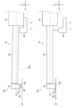
図5は、教示情報66の生成時の課題を説明するための説明である。教示情報66の生成時には、オペレータによる手動操作で検出器30の触針48及びスキッド54を被測定面Waに接触させるため、図5の符号5Aに示すように、検出器30を被測定面Waに押し付け過ぎると表面粗さ測定機18が破損するおそれがある。また逆に図5の符号5Bに示すように、検出器30の押し付けが足りないと、スキッド54が被測定面Waに十分に接触しないことで、表面粗さの測定精度が低下する。
Figure 5 is an explanatory diagram for explaining the problems that occur when generating the teaching information 66. When generating the teaching information 66, the operator manually brings the
従って、図5の符号5Cに示すように、検出器30の触針48及びスキッド54を被測定面Waに接触させた際に、検出器30をその揺動範囲Rの中央位置A1(中立位置ともいう)に位置決めする必要がある。そこで本実施形態では、オペレータの目視に頼ったり或いは検出器30の中央位置A1を検出する検出スイッチ(検出センサ)を表面粗さ測定機18に設けたりすることなく、検出器30の中央位置A1の位置決めを可能にする。具体的には本実施形態では、保持具80(図7参照)と、検出センサ46及び触針48とを用いて、検出器30を中央位置A1に位置決めする。
Therefore, as shown by
[第1実施形態の位置決め方法]
図6は、被測定面Waの教示情報66の生成時に、検出器30を中央位置A1に位置決めする位置決め方法の流れを示したフローチャートである。図7は、図6に示したフローチャートのステップS1を説明するための説明図である。図8は、図6に示したフローチャートのステップS2,S3を説明するための説明図である。図9は、図6に示したフローチャートのステップS4,S5を説明するための説明図である。図10は、図6に示したフローチャートのステップS6を説明するための説明図である。
[Positioning method of the first embodiment]
Fig. 6 is a flowchart showing the flow of a positioning method for positioning the
図6及び図7の符号7Aに示すように、オペレータは、検出器30の触針48及びスキッド54を被測定面Waに接触させる前、すなわち触針48がスキッド底面54aからZ1軸方向下方側に一定量だけ突出している状態で、保持具80を駆動部34に対して着脱自在に取り付ける(ステップS1)。
As shown by
保持具80は、駆動部34に取り付けられた場合に、図7の符号7Bに示すように検出器30を第2回転方向SW2に押圧することで、検出器30を第2回転方向SW2に一定角度回転させる。この際に、スキッド底面54aから突出している触針48の先端位置を、検出器30が中央位置A1にある場合のスキッド底面54aの高さ位置A2に一致させるように、保持具80の形状及び取付位置が調整されている。ここで、高さ位置A2については、表面粗さ測定機18の設計情報から求めたり或いは実測したりすることで既知である。このため、高さ位置A2に応じて保持具80の形状及び取付位置を調整可能である。
When the
このように、オペレータが駆動部34に保持具80を着脱自在に取り付けるだけで、触針48の先端位置を高さ位置A2に一致させることができる。また、検出器30は保持具80により支持されることで第1回転方向SW1への回転が規制された状態となる。従って、ステップS1は本発明の一致ステップに相当する。
In this way, the operator can align the tip position of the
図6及び図8に示すように、ステップS1の完了後、オペレータは、検出器30の触針48及びスキッド底面54aが被測定面Waに向けて移動するように、操作部62に対してロボットアーム16の操作入力を行う。この操作入力に応じてロボット制御部70がロボットアーム16を駆動して、触針48及びスキッド底面54aを被測定面Waに向けて移動させる(ステップS2、本発明の移動ステップに相当)。また、ロボット制御部70は教示情報66の記憶を開始する。
As shown in Figures 6 and 8, after completing step S1, the operator inputs an operation of the
ロボットアーム16の駆動が開始、すなわち表面粗さ測定機18の移動が開始すると、変位検出部76が、検出センサ46から信号処理部52を介して連続的に入力される検出信号に基づき、触針48の変位の有無を連続的に検出してその検出結果を表示部64へ逐次出力する(ステップS3、本発明の検出ステップに相当)。これにより、オペレータは、表示部64に表示され且つ触針48の変位の有無を視覚的に表した検出画面64aに基づき、触針48の先端が被測定面Waに接触したか否かを判別可能になる。そしてオペレータは、触針48の先端が被測定面Waに接触するまで、手動操作でのロボットアーム16の駆動を継続する(ステップS4でNO)。
When the
図6及び図9に示すように、オペレータは、表示部64に表示される検出画面64aに基づき、被測定面Waに触針48の先端が接触した場合に、操作部62に対してロボットアーム16の停止操作(操作部62の操作停止を含む)を行う(ステップS4でYES)。この操作停止に応じて、ロボット制御部70がロボットアーム16の駆動を停止させる(ステップS5、本発明の停止ステップに相当)。なお、ステップS2からステップS5までが本発明の第1接触ステップに相当する。
6 and 9, when the tip of the
ステップS5が完了すると、触針48の先端位置、すなわち高さ位置A2を被測定面Waに位置合わせすることができる。また、ロボット制御部70は、検出器30を接触させた被測定面Waに対応する教示情報66を記憶部60に記憶させる。
When step S5 is completed, the tip position of the
図6及び図10の符号XAに示すように、オペレータは、ロボットアーム16の駆動が停止した後、駆動部34から保持具80を取り外す(ステップS6、本発明の第2接触ステップに相当)。これにより、図10の符号XBに示すように、保持具80による検出器30の第1回転方向SW1の回転規制が解除されることで、検出器30が重力又は不図示の付勢部材等の復元力により第1回転方向SW1に回転して、スキッド底面54aが被測定面Waに接触する。この際に、高さ位置A2が被測定面Waに位置合わせされているので、スキッド底面54aが被測定面Waに接触している状態で検出器30が中央位置A1に位置決めされる。
As shown by XA in Figures 6 and 10, after the drive of the
以下、被測定面Waが複数存在する場合には、被測定面WaごとにステップS1からステップS6までの処理が繰り返し実行されることで、被測定面Waごとの教示情報66が記憶部60に記憶される。
Hereinafter, when there are multiple measurement surfaces Wa, the processing from step S1 to step S6 is repeatedly executed for each measurement surface Wa, and the teaching information 66 for each measurement surface Wa is stored in the
以上のように本実施形態では、保持具80と検出センサ46及び触針48とを用いることで、目視に頼ることなく検出器30を中央位置A1に位置決めすることできる。これにより、ロボットアーム16の教示に要する時間を短縮化し、オペレータごとの検出器30の中央位置A1への位置決め精度のばらつきの発生を低減し、さらに検出器30を被測定面Waに押し付け過ぎることによる表面粗さ測定機18の破損を防止可能である。また、検出器30が中央位置A1にあるか否かを検出するために、保持具80よりも高価な検出スイッチを表面粗さ測定機18に設ける必要がなくなるので、コストを低減させると共に検出スイッチの故障リスクをなくすことができる。その結果、検出器30の中央位置A1への位置決めを高精度且つ低コストに行うことができる。
As described above, in this embodiment, by using the
[第2実施形態の位置決め方法]
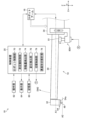
図11は、第2実施形態の表面粗さ測定システム10の一例を示した概略図である。上記第1実施形態では教示情報66の生成時における検出器30の中央位置A1への位置決めをオペレータが手動で行うが、第2実施形態では検出器30の中央位置A1への位置決めを自動で行う。
[Positioning method of the second embodiment]
11 is a schematic diagram showing an example of a surface
なお、第2実施形態の表面粗さ測定システム10は、駆動部34に保持具80Aが設けられており、且つ制御装置20が切替制御部79として機能し、且つロボット制御部70及び変位検出部76の機能が一部異なる点を除けば、上記第1実施形態の表面粗さ測定システム10と基本的に同じ構成である。このため、上記第1実施形態と機能又は構成上同一のものについては、同一符号を付してその説明は省略する。
The surface
保持具80Aは、ロボットアーム16、制御装置20、及び検出センサ46と共に本発明の位置決め装置を構成する。保持具80Aは、駆動部34に取り付けられており、Z1軸方向(図中ではZ軸方向と同一方向)に変位自在な押圧部81を有する。この保持具80Aは、後述の切替制御部79の制御の下、押圧部81により検出器30をZ軸方向下方側から押圧して第2回転方向SW2に一定角度だけ回転させる押圧状態(図13参照)と、押圧部81による検出器30の押圧を解除した押圧解除状態(図11参照)とに切り替え可能である。そして、保持具80Aが押圧状態に切り替えられた場合に、触針48の先端位置が既述の高さ位置A2に一致するように、保持具80Aの駆動部34への取付位置及び押圧部81の突出量が調整されている。
The
第2実施形態の変位検出部76は、被測定面Waごとの教示情報66の生成時には、検出センサ46から信号処理部52を介して連続的に入力される検出信号に基づき、触針48の変位の有無を連続的に検出してその検出結果をロボット制御部70へ逐次出力する。
When generating teaching information 66 for each measured surface Wa, the
第2実施形態のロボット制御部70(本発明の移動制御部に相当)は、教示情報66の生成時において保持具80Aが押圧解除状態から押圧状態に切り替えられた場合に、被測定面Waごとに予め作成された移動プログラムに従ってロボットアーム16を駆動して、検出器30(触針48及びスキッド底面54a)を被測定面Waに向けて移動させる。なお、移動プログラムは、検出器30の初期位置及び初期姿勢から被測定面Wa(目標点)までの簡易的な測定経路を示す情報である。
When the
また、ロボット制御部70は、ロボットアーム16の駆動開始後(表面粗さ測定機18の移動開始後)、変位検出部76から連続的に入力される触針48の変位の有無を示す検出結果に基づき、触針48の変位が所定の閾値よりも大きくなるか否か、すなわち触針48の先端が被測定面Waに接触したか否かを判定する。ロボット制御部70は、触針48の変位が所定の閾値以下である場合には、触針48の先端が被測定面Waに接触していないと判定し、表面粗さ測定機18の移動を継続する。そして、ロボット制御部70は、触針48の変位が所定の閾値よりも大きくなる場合には、触針48の先端が被測定面Waに接触したと判定して、ロボットアーム16の駆動を停止させる。
After the
切替制御部79は、保持具80Aの押圧状態と押圧解除状態との切り替えを制御する。この切替制御部79は、被測定面Waの教示情報66の生成開始時に保持具80Aを初期状態である押圧解除状態から押圧状態に切り替える。また、切替制御部79は、ロボット制御部70によるロボットアーム16の駆動中は保持具80Aの押圧状態を維持し、ロボット制御部70がロボットアーム16の駆動を停止した場合に保持具80Aを押圧状態から押圧解除状態に切り替える。
The switching
[第2実施形態の位置決め方法]
図12は、第2実施形態での被測定面Waの教示情報66の生成時において、検出器30を中央位置A1に位置決めする位置決め方法の流れを示したフローチャートである。図13は、図12に示したフローチャートのステップS1Aを説明するための説明図である。図14は、図12に示したフローチャートのステップS2A,S3Aを説明するための説明図である。図15は、図12に示したフローチャートのステップS4A、S5Aを説明するための説明図である。図16は、図12に示したフローチャートのステップS6Aを説明するための説明図である。
[Positioning method of the second embodiment]
Fig. 12 is a flowchart showing the flow of a positioning method for positioning the
図12及び図13に示すように、オペレータが操作部62に対して被測定面Waの教示情報66の生成開始操作を行うと、切替制御部79が保持具80Aを押圧解除状態から押圧状態に切り替える(ステップS1A、本発明の一致ステップに相当)。これにより、保持具80Aの押圧部81により検出器30が押圧されて、この検出器30が第2回転方向SW2に一定角度だけ回転することで、第1実施形態と同様に触針48の先端位置を高さ位置A2に一致させることができる。またこの場合に、検出器30は押圧部81により第1回転方向SW1への回転が規制される。
As shown in Figures 12 and 13, when the operator operates the
図12及び図14に示すように、保持具80Aが押圧状態に切り替えられると、ロボット制御部70が、被測定面Waに対応する移動プログラムに従ってロボットアーム16を駆動して、検出器30を被測定面Waに向けて移動させる(ステップS2A、本発明の移動ステップに相当)。また、ロボット制御部70は教示情報66の記憶を開始する。
As shown in Figures 12 and 14, when the
ロボットアーム16の駆動が開始、すなわち表面粗さ測定機18の移動が開始すると、変位検出部76が、検出センサ46から信号処理部52を介して連続的に入力される検出信号に基づき、触針48の変位の有無を連続的に検出してその検出結果をロボット制御部70へ逐次出力する(ステップS3A、本発明の検出ステップに相当)。これにより、ロボット制御部70は、触針48の先端が被測定面Waに接触したか否かを判定することができる。そして、ロボット制御部70は、触針48の先端が被測定面Waに接触していないと判定した場合、ロボットアーム16の駆動を継続する(ステップS4AでNO)。
When the
一方、図12及び図15に示すように、ロボット制御部70は、変位検出部76から逐次入力される検出結果に基づき、触針48の先端が被測定面Waに接触したと判定した場合には、ロボットアーム16の駆動を停止させる(ステップS4AでYES、ステップS5A、本発明の停止ステップに相当)。なお、ステップS2AからステップS5Aまでが本発明の第1接触ステップに相当する。これにより、第1実施形態と同様に、触針48の先端位置、すなわち高さ位置A2を被測定面Waに位置合わせすることができる。また、ロボット制御部70は、被測定面Waに対応する教示情報66を記憶部60に記憶させる。
On the other hand, as shown in Figures 12 and 15, when the
図12及び図16に示すように、ロボットアーム16の駆動が停止すると、切替制御部79が保持具80Aを押圧状態から押圧解除状態に切り替える(ステップS6A、本発明の第2接触ステップに相当)。これにより、保持具80Aによる検出器30の第1回転方向SW1の回転規制が解除されることで、第1実施形態と同様に検出器30が第1回転方向SW1に回転してスキッド底面54aが被測定面Waに接触する。その結果、スキッド底面54aが被測定面Waに接触している状態で検出器30が中央位置A1に位置決めされる。
As shown in Figures 12 and 16, when the drive of the
以下、被測定面Waが複数存在する場合には、被測定面WaごとにステップS1AからステップS6Aまでの処理が繰り返し実行されることで、被測定面Waごとの教示情報66が記憶部60に記憶される。
Hereinafter, when there are multiple measurement surfaces Wa, the processing from step S1A to step S6A is repeatedly executed for each measurement surface Wa, and the teaching information 66 for each measurement surface Wa is stored in the
以上のように第2実施形態では、検出器30の中央位置A1への位置決めを自動で実行することができる。その結果、この位置決めを第1実施形態よりも短時間で完了させることができる。また、検出器30の中央位置A1への位置決め精度のばらつきを第1実施形態よりも低減させることができる。
As described above, in the second embodiment, the positioning of the
[その他]
上記各実施形態では、表面粗さ測定機18を保持するロボットアーム16により、検出器30の触針48及びスキッド底面54aを被測定面Waに接触させているが、検出器30(触針48及びスキッド底面54a)と、被測定面Wa(ステージ12)とのいずれか一方を他方に向けて移動可能な各種ロボットを用いてもよい。また、ロボットを用いる代わりに、検出器30と被測定面Waとのいずれか一方を他方に向けて移動可能な公知の各種移動機構(アクチュエータ)を用いてもよい。
[others]
In each of the above embodiments, the
上記各実施形態では、被測定面Waの表面粗さを測定する表面粗さ測定機18の検出器30の中央位置A1への位置決めを例に挙げて説明したが、被測定面Waの輪郭形状を測定する輪郭形状測定機などのように触針48及びスキッド54を有する各種表面形状測定機の検出器の位置決めに本発明を適用可能である。なお、被測定面Waが水平面(略水平面を含む)に限定される場合には、触針48及びスライラス先端部42bの重さを利用してスタイラス42を第1回転方向SW1に付勢してもよく、この場合には付勢部材44を省略してもよい。
In each of the above embodiments, the positioning of the
10 測定システム
12 ステージ
14 ロボット基台
16 ロボットアーム
16a1~16a5 アーム
16b 関節部
16c エンドエフェクタ
16d アダプタ
18 測定機
20 制御装置
30 検出器
30a ハウジング
32 ノーズピース
34 駆動部
40 揺動支点
42 スタイラス
42a スタイラス本体部
42b スタイラス先端部
42c スタイラス基端部
44 付勢部材
46 検出センサ
46a コア
46b コイル
48 触針
50 信号ケーブル
52 信号処理部
54 スキッド
54a スキッド底面
54b 触針挿通穴
60 記憶部
62 操作部
64 表示部
64a 検出画面
66 教示情報
70 ロボット制御部
72 測定機制御部
74 移動量検出部
76 変位検出部
78 表面形状解析部
79 切替制御部
80 保持具
80A 保持具
81 押圧部
A1 中央位置
A2 高さ位置
R 揺動範囲
SW1 第1回転方向
SW2 第2回転方向
W ワーク
Wa 被測定面
10
Claims (6)
前記検出器を前記第1回転方向と前記第2回転方向とに揺動自在に保持し、且つ前記検出器を前記揺動支点の軸方向に垂直な駆動方向に移動させる駆動部と、
を備える表面形状測定機において、
前記スキッドを前記被測定面に接触させた場合に、前記検出器の揺動範囲の中央位置に前記検出器を位置決めする位置決め方法であって、
前記スキッドを前記被測定面に接触させる前に前記検出器を前記第2回転方向に回転させて、前記検出器内での前記スタイラスに対する前記付勢部材の付勢により前記底面から突出した前記触針の先端位置を、前記検出器が前記中央位置にあると仮定した場合の前記底面の高さ位置に一致させる一致ステップと、
前記一致ステップでの前記検出器の姿勢を維持した状態で、前記被測定面に対して前記検出器を相対移動させて前記触針の先端を前記被測定面に接触させる第1接触ステップと、
前記第1接触ステップの完了後に、前記検出器を前記第1回転方向に回転させて前記底面を前記被測定面に接触させる第2接触ステップと、
を有する位置決め方法。 a detector comprising: a skid having a bottom surface in contact with a surface to be measured and a through hole opening to the bottom surface; a stylus supported so as to be swingable about a swing fulcrum; a contact needle provided at a tip of the stylus which approaches the skid when the stylus rotates in a first rotation direction and moves away from the skid when the stylus rotates in a second rotation direction opposite to the first rotation direction and which is inserted into the through hole; and a biasing member which biases the stylus in the first rotation direction;
a drive unit that holds the detector so as to be swingable in the first rotation direction and the second rotation direction and moves the detector in a drive direction perpendicular to an axial direction of the swing fulcrum;
A surface shape measuring instrument comprising:
A method for positioning the detector at a center position of a swing range of the detector when the skid is brought into contact with the surface to be measured, comprising the steps of:
a matching step of rotating the detector in the second rotation direction before the skid is brought into contact with the surface to be measured , and matching a tip position of the stylus protruding from the bottom surface by the biasing member against the stylus in the detector with a height position of the bottom surface when the detector is assumed to be at the central position;
a first contact step of moving the detector relative to the surface to be measured while maintaining the orientation of the detector in the matching step , thereby bringing the tip of the stylus into contact with the surface to be measured;
a second contacting step of rotating the detector in the first rotation direction to bring the bottom surface into contact with the surface to be measured after the first contacting step is completed;
The positioning method includes:
前記被測定面に対して前記検出器を相対移動させて、前記触針の先端及び前記被測定面の一方を他方に向けて移動させる移動ステップと、
前記移動ステップが実行されている間、前記触針の変位の有無を連続的に検出する検出ステップと、
前記検出ステップで前記触針の変位が検出された場合に前記移動ステップを停止させる停止ステップと、
を含む請求項1に記載の位置決め方法。 The first contacting step comprises:
a moving step of moving the detector relative to the surface to be measured, so as to move one of the tip of the stylus and the surface to be measured toward the other;
a detection step of continuously detecting the presence or absence of displacement of the stylus while the moving step is being performed;
a stopping step of stopping the moving step when the displacement of the stylus is detected in the detecting step;
The method of claim 1 , further comprising:
前記第2接触ステップでは、前記駆動部から前記保持具を取り外して前記回転規制を解除することで、前記検出器を前記第1回転方向に回転させる請求項1から3のいずれか1項に記載の位置決め方法。 In the matching step, a holder is detachably attached to the drive unit, and the holder presses the detector and rotates it by a certain angle in the second rotation direction to match the tip position of the stylus to the height position, and the holder performs rotation regulation to regulate the rotation of the detector in the first rotation direction.
The positioning method according to claim 1 , wherein in the second contact step, the holder is detached from the drive unit to release the rotation restriction, thereby rotating the detector in the first rotation direction.
前記検出器を前記第1回転方向と前記第2回転方向とに揺動自在に保持し、且つ前記検出器を前記揺動支点の軸方向に垂直な駆動方向に移動させる駆動部と、
を備える表面形状測定機において、
前記スキッドを前記被測定面に接触させた場合に、前記検出器の揺動範囲の中央位置に前記検出器を位置決めする位置決め装置であって、
前記駆動部に取り付けられた保持具であって、且つ前記検出器を押圧して前記第2回転方向に回転させる押圧状態と、前記検出器の押圧を解除した押圧解除状態と、に切り替え可能な保持具と、
前記被測定面に対して前記検出器を相対移動させる相対移動部と、
前記保持具の前記押圧状態と前記押圧解除状態との切り替えを制御する切替制御部と、
前記スキッドを前記被測定面に接触させる前に前記切替制御部により前記保持具が前記押圧状態に切り替えられた場合に、前記相対移動部を駆動して、前記触針の先端及び前記被測定面の一方を他方に向けて移動させる移動制御部と、
前記相対移動部の駆動中に前記触針の変位の有無を連続的に検出する変位検出部と、
を備え、
前記押圧状態の前記保持具により前記検出器が前記第2回転方向に回転された場合には、前記検出器内での前記スタイラスに対する前記付勢部材の付勢により前記底面から前記触針が突出し、
前記押圧状態の前記保持具は、前記付勢部材の付勢により前記底面から突出した前記触針の先端位置が、前記検出器が前記中央位置にあると仮定した場合の前記底面の高さ位置に一致するように前記検出器の姿勢を維持し、
前記移動制御部が、前記変位検出部により前記触針の変位が検出された場合に前記相対移動部の駆動を停止させ、
前記切替制御部が、前記移動制御部による前記相対移動部の駆動が停止された場合に、前記保持具を前記押圧状態から前記押圧解除状態に切り替えることで、前記検出器を前記第1回転方向に回転させて前記被測定面に前記底面を接触させる位置決め装置。 a detector comprising: a skid having a bottom surface in contact with a surface to be measured and a through hole opening to the bottom surface; a stylus supported so as to be swingable about a swing fulcrum; a contact needle provided at a tip of the stylus which approaches the skid when the stylus rotates in a first rotation direction and moves away from the skid when the stylus rotates in a second rotation direction opposite to the first rotation direction and which is inserted into the through hole; and a biasing member which biases the stylus in the first rotation direction;
a drive unit that holds the detector so as to be swingable in the first rotation direction and the second rotation direction and moves the detector in a drive direction perpendicular to an axial direction of the swing fulcrum;
A surface shape measuring instrument comprising:
A positioning device that positions the detector at a center position of a swing range of the detector when the skid is brought into contact with the surface to be measured,
a holder attached to the drive unit and switchable between a pressing state in which the detector is pressed to rotate in the second rotation direction and a pressing release state in which the detector is released from the pressing;
a relative movement unit that moves the detector relative to the surface to be measured;
a switching control unit that controls switching between the pressed state and the released state of the holder;
a movement control unit that drives the relative movement unit to move one of the tip of the stylus and the surface to be measured toward the other when the holder is switched to the pressing state by the switching control unit before the skid is brought into contact with the surface to be measured;
a displacement detection unit that continuously detects the presence or absence of displacement of the stylus while the relative moving unit is being driven;
Equipped with
When the detector is rotated in the second rotation direction by the holder in the pressed state, the stylus is biased by the biasing member against the stylus in the detector, causing the stylus to protrude from the bottom surface,
the holder in the pressed state maintains the attitude of the detector so that the tip position of the stylus protruding from the bottom surface by the biasing force of the biasing member coincides with the height position of the bottom surface when the detector is assumed to be at the central position ;
the movement control unit stops driving the relative movement unit when the displacement of the stylus is detected by the displacement detection unit,
A positioning device in which, when the driving of the relative moving part by the movement control part is stopped, the switching control part switches the holder from the pressed state to the released state, thereby rotating the detector in the first rotation direction and bringing the bottom surface into contact with the measured surface.
Priority Applications (1)
| Application Number | Priority Date | Filing Date | Title |
|---|---|---|---|
| JP2021028750A JP7617397B2 (en) | 2021-02-25 | 2021-02-25 | Positioning method and positioning device |
Applications Claiming Priority (1)
| Application Number | Priority Date | Filing Date | Title |
|---|---|---|---|
| JP2021028750A JP7617397B2 (en) | 2021-02-25 | 2021-02-25 | Positioning method and positioning device |
Publications (2)
| Publication Number | Publication Date |
|---|---|
| JP2022129888A JP2022129888A (en) | 2022-09-06 |
| JP7617397B2 true JP7617397B2 (en) | 2025-01-20 |
Family
ID=83150679
Family Applications (1)
| Application Number | Title | Priority Date | Filing Date |
|---|---|---|---|
| JP2021028750A Active JP7617397B2 (en) | 2021-02-25 | 2021-02-25 | Positioning method and positioning device |
Country Status (1)
| Country | Link |
|---|---|
| JP (1) | JP7617397B2 (en) |
Citations (3)
| Publication number | Priority date | Publication date | Assignee | Title |
|---|---|---|---|---|
| JP2001241905A (en) | 2000-03-02 | 2001-09-07 | Tokyo Seimitsu Co Ltd | Roughness measuring instrument |
| JP2014081324A (en) | 2012-10-18 | 2014-05-08 | Mitsutoyo Corp | Surface roughness measurement unit and three-dimensional measurement device |
| JP6800421B1 (en) | 2019-11-29 | 2020-12-16 | 株式会社東京精密 | Measuring device and measuring method |
Family Cites Families (2)
| Publication number | Priority date | Publication date | Assignee | Title |
|---|---|---|---|---|
| JPS6230103U (en) * | 1985-08-08 | 1987-02-23 | ||
| JPS63289410A (en) * | 1987-05-20 | 1988-11-25 | Mitsutoyo Corp | Three-dimensional measuring instrument |
-
2021
- 2021-02-25 JP JP2021028750A patent/JP7617397B2/en active Active
Patent Citations (3)
| Publication number | Priority date | Publication date | Assignee | Title |
|---|---|---|---|---|
| JP2001241905A (en) | 2000-03-02 | 2001-09-07 | Tokyo Seimitsu Co Ltd | Roughness measuring instrument |
| JP2014081324A (en) | 2012-10-18 | 2014-05-08 | Mitsutoyo Corp | Surface roughness measurement unit and three-dimensional measurement device |
| JP6800421B1 (en) | 2019-11-29 | 2020-12-16 | 株式会社東京精密 | Measuring device and measuring method |
Also Published As
| Publication number | Publication date |
|---|---|
| JP2022129888A (en) | 2022-09-06 |
Similar Documents
| Publication | Publication Date | Title |
|---|---|---|
| JP7630534B2 (en) | Coordinate positioning machine | |
| JP4638327B2 (en) | Parallel mechanism device, parallel mechanism device calibration method, calibration program, and recording medium | |
| CN109655023B (en) | System for determining the state of a tool positioning machine | |
| EP2564151B1 (en) | Coordinate positioning apparatus with interchangeable task module counterweight and method of operating it | |
| JP5124579B2 (en) | Surface sensing device | |
| JP7531653B2 (en) | Method for calibrating a surface sensing device, corresponding calibration program for a control computer and corresponding calibration kit - Patents.com | |
| JPH05256602A (en) | Calibrating and measuring apparatus | |
| WO2009106830A1 (en) | Modular scanning and machining apparatus | |
| JP2006300823A (en) | Surface roughness/contour shape measuring system | |
| JP2021092531A (en) | Measurement device and measurement method | |
| JP7617397B2 (en) | Positioning method and positioning device | |
| JP7410189B2 (en) | robot calibration device | |
| JP2019120633A (en) | Surface shape measurement machine | |
| EP3736527A1 (en) | Surface shape measurement device | |
| JPS63289410A (en) | Three-dimensional measuring instrument | |
| JP7038308B2 (en) | Surface shape measuring machine | |
| JP7592970B2 (en) | Shape measuring device | |
| JP5491098B2 (en) | Calibration method for touch probe of machine tool and machine tool | |
| WO2025104904A1 (en) | Robot control device | |
| JP2025524182A (en) | Coordinate positioning machine | |
| JPH0694114B2 (en) | Origin adjustment device for horizontal joint type robot | |
| JPS58160808A (en) | Method for measuring three-dimensional free curved surface and probe device | |
| JP2020139858A (en) | Inspection jig, gauge inspection machine and gauge holding method |
Legal Events
| Date | Code | Title | Description |
|---|---|---|---|
| A621 | Written request for application examination |
Free format text: JAPANESE INTERMEDIATE CODE: A621 Effective date: 20231228 |
|
| A977 | Report on retrieval |
Free format text: JAPANESE INTERMEDIATE CODE: A971007 Effective date: 20240626 |
|
| A131 | Notification of reasons for refusal |
Free format text: JAPANESE INTERMEDIATE CODE: A131 Effective date: 20240726 |
|
| A521 | Request for written amendment filed |
Free format text: JAPANESE INTERMEDIATE CODE: A523 Effective date: 20240911 |
|
| TRDD | Decision of grant or rejection written | ||
| A01 | Written decision to grant a patent or to grant a registration (utility model) |
Free format text: JAPANESE INTERMEDIATE CODE: A01 Effective date: 20241203 |
|
| A61 | First payment of annual fees (during grant procedure) |
Free format text: JAPANESE INTERMEDIATE CODE: A61 Effective date: 20241216 |
|
| R150 | Certificate of patent or registration of utility model |
Ref document number: 7617397 Country of ref document: JP Free format text: JAPANESE INTERMEDIATE CODE: R150 |