JP7608887B2 - Non-contact voltage measuring device - Google Patents
Non-contact voltage measuring device Download PDFInfo
- Publication number
- JP7608887B2 JP7608887B2 JP2021039429A JP2021039429A JP7608887B2 JP 7608887 B2 JP7608887 B2 JP 7608887B2 JP 2021039429 A JP2021039429 A JP 2021039429A JP 2021039429 A JP2021039429 A JP 2021039429A JP 7608887 B2 JP7608887 B2 JP 7608887B2
- Authority
- JP
- Japan
- Prior art keywords
- capacitor
- electric wire
- electrode
- conductor
- capacitance
- Prior art date
- Legal status (The legal status is an assumption and is not a legal conclusion. Google has not performed a legal analysis and makes no representation as to the accuracy of the status listed.)
- Active
Links
Images


Classifications
-
- G—PHYSICS
- G01—MEASURING; TESTING
- G01R—MEASURING ELECTRIC VARIABLES; MEASURING MAGNETIC VARIABLES
- G01R15/00—Details of measuring arrangements of the types provided for in groups G01R17/00 - G01R29/00, G01R33/00 - G01R33/26 or G01R35/00
- G01R15/14—Adaptations providing voltage or current isolation, e.g. for high-voltage or high-current networks
- G01R15/16—Adaptations providing voltage or current isolation, e.g. for high-voltage or high-current networks using capacitive devices
-
- G—PHYSICS
- G01—MEASURING; TESTING
- G01R—MEASURING ELECTRIC VARIABLES; MEASURING MAGNETIC VARIABLES
- G01R19/00—Arrangements for measuring currents or voltages or for indicating presence or sign thereof
Landscapes
- Physics & Mathematics (AREA)
- General Physics & Mathematics (AREA)
- Measuring Instrument Details And Bridges, And Automatic Balancing Devices (AREA)
- Measurement Of Current Or Voltage (AREA)
Description
本発明は、電線の導体と非接触で当該導体の電圧を測定する非接触電圧測定装置に関する。 The present invention relates to a non-contact voltage measuring device that measures the voltage of an electric wire conductor without contacting the conductor.
2つの電極を備え、2つの電極の各々に誘起される電圧から電線の導体の電圧を算出する非接触電圧測定装置が知られている。 A non-contact voltage measuring device is known that has two electrodes and calculates the voltage of the conductor of an electric wire from the voltage induced in each of the two electrodes.
しかし、このような非接触電圧測定装置では、インバータ電圧駆動を行う回転機に供給される駆動電圧を正確に算出できない。インバータ電圧駆動を行う回転機の駆動電圧を測定するためには、複数の周波数成分を含む電圧の測定を行う必要があるためである。 However, such non-contact voltage measurement devices cannot accurately calculate the drive voltage supplied to a rotating machine that is inverter-driven. This is because in order to measure the drive voltage of a rotating machine that is inverter-driven, it is necessary to measure a voltage that includes multiple frequency components.
そこで、特許文献1に開示された非接触電圧測定装置は、第1電極に接続された第1電圧計測部と、第2電極に接続された第2電圧計測部と、各電圧計測部で計測されたデータを時間領域から周波数領域に変換する時間領域・周波数領域変換部と、周波数領域に変換されたデータから、周波数ごとの電圧値を演算する周波数ごと電圧値演算部と、周波数ごとの電圧値のデータを、周波数領域から時間領域に変換する周波数領域・時間領域変換部と、時間領域に変換されたデータから、導体の電圧を演算する導体電圧演算部とを備える。つまり、特許文献1に開示された非接触電圧測定装置では、時間領域・周波数領域変換部と、周波数ごと電圧値演算部と、周波数領域・時間領域変換部とを備えることによって、複数の周波数成分を含む電圧の測定を行うことができる。 The non-contact voltage measuring device disclosed in Patent Document 1 includes a first voltage measuring unit connected to the first electrode, a second voltage measuring unit connected to the second electrode, a time domain/frequency domain conversion unit that converts data measured by each voltage measuring unit from the time domain to the frequency domain, a frequency-by-frequency voltage value calculation unit that calculates a voltage value for each frequency from the data converted to the frequency domain, a frequency domain/time domain conversion unit that converts the data of the voltage value for each frequency from the frequency domain to the time domain, and a conductor voltage calculation unit that calculates the voltage of the conductor from the data converted to the time domain. In other words, the non-contact voltage measuring device disclosed in Patent Document 1 can measure a voltage including multiple frequency components by including a time domain/frequency domain conversion unit, a frequency-by-frequency voltage value calculation unit, and a frequency domain/time domain conversion unit.
しかし、特許文献1に開示された非接触電圧測定装置では、各電圧計測部で計測されたデータを時間領域から周波数領域に変換して、周波数ごとに電圧値を演算し、周波数ごとのデータを周波数領域から時間領域に変換する必要がある。この場合、演算過程において、フーリエ変換等を用いる必要があり、演算が複雑化してしまう。 However, in the non-contact voltage measuring device disclosed in Patent Document 1, it is necessary to convert the data measured by each voltage measuring unit from the time domain to the frequency domain, calculate the voltage value for each frequency, and convert the data for each frequency from the frequency domain to the time domain. In this case, it is necessary to use a Fourier transform or the like in the calculation process, which makes the calculation complicated.
従って、本発明の目的は、前記課題を解決することにあって、従来技術より簡単な演算で、しかも環境変化に対応してリアルタイムで電線の導体の電圧を測定することができる非接触電圧測定装置を提供することにある。 The object of the present invention is therefore to solve the above problems by providing a non-contact voltage measuring device that can measure the voltage of an electric wire conductor in real time with simpler calculations than conventional techniques and in response to environmental changes.
前記目的を達成するために、本発明は以下のように構成する。
本発明の一態様に係る非接触電圧測定装置は、
互いに離隔して設けられる第1電極及び第2電極と、
前記第1電極と接続される第1コンデンサと、
前記第1コンデンサと互いに直列に接続される第1増幅回路と、
前記第2電極と接続される第2コンデンサと、
前記第2コンデンサと互いに直列に接続される第2増幅回路と、
演算部と、を備え、
前記第1電極及び前記第2電極の各々は、電線の導体と非接触で且つ前記電線の導体と対向し、
前記第1コンデンサは、前記第1増幅回路の入力端子に接続され、
前記第2コンデンサは、前記第2増幅回路の入力端子に接続され、
前記第1増幅回路は、出力端子と入力端子との間に接続される第3コンデンサを備え、
前記第2増幅回路は、出力端子と入力端子との間に接続される第4コンデンサを備え、
前記演算部は、
前記第1コンデンサの容量、前記第2コンデンサの容量、前記第3コンデンサの容量、前記第4コンデンサの容量、前記第1増幅回路の出力端子の電圧、及び前記第2増幅回路の出力端子の電圧に基づいて、前記電線の導体の電圧を算出する。
In order to achieve the above object, the present invention is configured as follows.
A non-contact voltage measuring device according to one aspect of the present invention comprises:
a first electrode and a second electrode spaced apart from each other;
a first capacitor connected to the first electrode;
a first amplifier circuit connected in series with the first capacitor;
a second capacitor connected to the second electrode;
a second amplifier circuit connected in series with the second capacitor;
A calculation unit,
each of the first electrode and the second electrode faces a conductor of the electric wire without being in contact with the conductor of the electric wire;
the first capacitor is connected to an input terminal of the first amplifier circuit;
the second capacitor is connected to an input terminal of the second amplifier circuit;
the first amplifier circuit includes a third capacitor connected between an output terminal and an input terminal;
the second amplifier circuit includes a fourth capacitor connected between the output terminal and the input terminal;
The calculation unit is
The voltage of the conductor of the electric wire is calculated based on the capacitance of the first capacitor, the capacitance of the second capacitor, the capacitance of the third capacitor, the capacitance of the fourth capacitor, the voltage of the output terminal of the first amplifier circuit, and the voltage of the output terminal of the second amplifier circuit.
本発明によれば、従来技術より簡単な演算で、しかも環境変化に対応してリアルタイムで電線の導体の電圧を測定することができる。 The present invention makes it possible to measure the voltage of an electric wire conductor in real time, with simpler calculations than conventional technology, and in response to environmental changes.
本発明の一態様に係る非接触電圧測定装置は、
互いに離隔して設けられる第1電極及び第2電極と、
前記第1電極と接続される第1コンデンサと、
前記第1コンデンサと互いに直列に接続される第1増幅回路と、
前記第2電極と接続される第2コンデンサと、
前記第2コンデンサと互いに直列に接続される第2増幅回路と、
演算部と、を備え、
前記第1電極及び前記第2電極の各々は、電線の導体と非接触で且つ前記電線の導体と対向し、
前記第1コンデンサは、前記第1増幅回路の入力端子に接続され、
前記第2コンデンサは、前記第2増幅回路の入力端子に接続され、
前記第1増幅回路は、出力端子と入力端子との間に接続される第3コンデンサを備え、
前記第2増幅回路は、出力端子と入力端子との間に接続される第4コンデンサを備え、
前記演算部は、
前記第1コンデンサの容量、前記第2コンデンサの容量、前記第3コンデンサの容量、前記第4コンデンサの容量、前記第1増幅回路の出力端子の電圧、及び前記第2増幅回路の出力端子の電圧に基づいて、前記電線の導体の電圧を算出する。
A non-contact voltage measuring device according to one aspect of the present invention comprises:
a first electrode and a second electrode spaced apart from each other;
a first capacitor connected to the first electrode;
a first amplifier circuit connected in series with the first capacitor;
a second capacitor connected to the second electrode;
a second amplifier circuit connected in series with the second capacitor;
A calculation unit,
each of the first electrode and the second electrode faces a conductor of the electric wire without being in contact with the conductor of the electric wire;
the first capacitor is connected to an input terminal of the first amplifier circuit;
the second capacitor is connected to an input terminal of the second amplifier circuit;
the first amplifier circuit includes a third capacitor connected between an output terminal and an input terminal;
the second amplifier circuit includes a fourth capacitor connected between the output terminal and the input terminal;
The calculation unit is
The voltage of the conductor of the electric wire is calculated based on the capacitance of the first capacitor, the capacitance of the second capacitor, the capacitance of the third capacitor, the capacitance of the fourth capacitor, the voltage of the output terminal of the first amplifier circuit, and the voltage of the output terminal of the second amplifier circuit.
この構成によれば、演算部による電線の導体の電圧の算出過程において、周波数の項を消すことができる。これにより、フーリエ変換等を用いた複雑な演算を行うことなく、電線の導体の電圧を算出することができる。つまり、従来技術より簡単な演算で、複数の周波数成分を含む電圧の測定を行うことができる。 With this configuration, the frequency term can be eliminated in the process of calculating the voltage of the electric wire conductor by the calculation unit. This makes it possible to calculate the voltage of the electric wire conductor without performing complex calculations such as Fourier transform. In other words, it is possible to measure voltages containing multiple frequency components with calculations that are simpler than those of conventional technology.
この構成によれば、第1電極と電線の導体との間の結合容量と、第2電極と電線の導体との間の結合容量とを常時求めることができる。そのため、温度及び湿度の変化、電線の経年劣化等の環境変化による結合容量の変化にリアルタイムで対応することができる。 With this configuration, the coupling capacitance between the first electrode and the conductor of the electric wire and the coupling capacitance between the second electrode and the conductor of the electric wire can be constantly calculated. Therefore, it is possible to respond in real time to changes in coupling capacitance due to environmental changes such as changes in temperature and humidity, and deterioration of the electric wire over time.
前記非接触電圧測定装置において、前記演算部はさらに、前記第1電極と前記電線の導体との間の第1結合容量、前記第2電極と前記電線の導体との間の第2結合容量を算出してもよい。 In the non-contact voltage measuring device, the calculation unit may further calculate a first coupling capacitance between the first electrode and the conductor of the electric wire, and a second coupling capacitance between the second electrode and the conductor of the electric wire.
この構成によれば、演算部は、電線の導体の電圧と同様にして、第1コンデンサ~第4コンデンサの容量、前記第1増幅回路の出力端子の電圧、及び前記第2増幅回路の出力端子の電圧に基づいて、第1結合容量及び第2結合容量を算出することができる。 With this configuration, the calculation unit can calculate the first coupling capacitance and the second coupling capacitance based on the capacitances of the first to fourth capacitors, the voltage of the output terminal of the first amplifier circuit, and the voltage of the output terminal of the second amplifier circuit, in a manner similar to the voltage of the conductor of the electric wire.
前記非接触電圧測定装置において、前記演算部は、前記第1結合容量と前記第2結合容量とが等しいとして、前記第1結合容量と前記第2結合容量とを算出してもよい。 In the non-contact voltage measuring device, the calculation unit may calculate the first coupling capacitance and the second coupling capacitance by assuming that the first coupling capacitance and the second coupling capacitance are equal.
この構成によれば、第1結合容量と第2結合容量とを簡単な演算で算出することができる。 With this configuration, the first coupling capacitance and the second coupling capacitance can be calculated by a simple calculation.
前記非接触電圧測定装置において、前記演算部は、前記第1結合容量と前記第2結合容量との差が一定であるとして、前記第1結合容量と前記第2結合容量とを算出してもよい。 In the non-contact voltage measuring device, the calculation unit may calculate the first coupling capacitance and the second coupling capacitance assuming that the difference between the first coupling capacitance and the second coupling capacitance is constant.
この構成によれば、第1結合容量と第2結合容量とが等しくない場合であっても、第1結合容量と第2結合容量とを算出することができる。 With this configuration, even if the first coupling capacitance and the second coupling capacitance are not equal, the first coupling capacitance and the second coupling capacitance can be calculated.
前記非接触電圧測定装置において、前記演算部は、以下の式(1)から式(6)を用いて、
Z1=(CL1+C1)/jωCL1C1・・・(1)
Z2=(CL2+C2)/jωCL2C2・・・(2)
Z3=1/jωC3・・・(3)
Z4=1/jωC4・・・(4)
V1=-(Z3/Z1)VL・・・(5)
V2=-(Z4/Z2)VL・・・(6)
ここで、
CL1は、前記第1電極と前記電線の導体との間の第1結合容量であり、
CL2は、前記第2電極と前記電線の導体との間の第2結合容量であり、
C1は、前記第1コンデンサの容量であり、
C2は、前記第2コンデンサの容量であり、
C3は、前記第3コンデンサの容量であり、
C4は、前記第4コンデンサの容量であり、
Z1は、前記第1結合容量を蓄えるコンデンサと前記第1コンデンサとの合成インピーダンスであり、
Z2は、前記第2結合容量を蓄えるコンデンサと前記第2コンデンサとの合成インピーダンスであり、
Z3は、前記第3コンデンサのインピーダンスであり、
Z4は、前記第4コンデンサのインピーダンスであり、
V1は、前記第1増幅回路の出力端子の電圧であり、
V2は、前記第2増幅回路の出力端子の電圧であり、
VLは、前記電線の導体の電圧であり、
前記電線の導体の電圧を算出してもよい。
In the non-contact voltage measuring device, the calculation unit calculates, using the following equations (1) to (6),
Z 1 = (C L1 + C 1 )/jωC L1 C 1 ...(1)
Z 2 = (C L2 + C 2 )/jωC L2 C 2 ...(2)
Z 3 = 1/jωC 3 ...(3)
Z 4 = 1/jωC 4 ...(4)
V 1 =-(Z 3 /Z 1 )V L ...(5)
V 2 =-(Z 4 /Z 2 )V L ...(6)
Where:
C L1 is a first coupling capacitance between the first electrode and the conductor of the wire;
C L2 is a second coupling capacitance between the second electrode and the wire conductor;
C1 is the capacitance of the first capacitor;
C2 is the capacitance of the second capacitor;
C3 is the capacitance of the third capacitor;
C4 is the capacitance of the fourth capacitor;
Z1 is a composite impedance of the capacitor storing the first coupling capacitance and the first capacitor,
Z2 is a composite impedance of the capacitor storing the second coupling capacitance and the second capacitor,
Z3 is the impedance of the third capacitor;
Z4 is the impedance of the fourth capacitor;
V1 is the voltage at the output terminal of the first amplifier circuit;
V2 is the voltage at the output terminal of the second amplifier circuit;
VL is the voltage of the conductor of the wire;
The voltage of the conductor of the wire may be calculated.
この構成によれば、CL1とCL2との関係が規定されることにより、例えばCL1=CL2と規定されることにより、式(1)及び式(3)が代入された式(5)と、式(2)及び式(4)が代入された式(6)との連立方程式が導出される。この連立方程式を解くことによって、第1結合容量CL1、第2結合容量CL2、及び電線の導体の電圧VLを算出することができる。前記の連立方程式を解く過程において、ωの項(周波数の項)が消える。これにより、フーリエ変換等を用いた複雑な演算を行うことなく、当該連立方程式を解くことができる。つまり、従来技術より簡単な演算で、複数の周波数成分を含む電圧の測定を行うことができる。 According to this configuration, by defining the relationship between C L1 and C L2 , for example, by defining C L1 =C L2 , simultaneous equations are derived, which are the equation (5) into which equations (1) and (3) are substituted, and the equation (6) into which equations (2) and (4) are substituted. By solving this simultaneous equation, the first coupling capacitance C L1 , the second coupling capacitance C L2 , and the voltage V L of the conductor of the electric wire can be calculated. In the process of solving the simultaneous equations, the ω term (frequency term) disappears. This makes it possible to solve the simultaneous equations without performing complex calculations using Fourier transforms or the like. In other words, it is possible to measure a voltage including multiple frequency components with calculations simpler than those of the prior art.
前記非接触電圧測定装置はさらに、前記電線を把持する把持部材を備えてもよく、前記第1電極及び前記第2電極は、前記把持部材に設けられてもよく、前記第1電極及び前記第2電極の各々は、前記把持部材が前記電線を把持するときに、前記電線の導体と対向してもよい。 The non-contact voltage measuring device may further include a gripping member that grips the electric wire, and the first electrode and the second electrode may be provided on the gripping member, and each of the first electrode and the second electrode may face the conductor of the electric wire when the gripping member grips the electric wire.
この構成によれば、把持部材が電線を把持することによって、電線の導体の電圧を算出することができる。 With this configuration, the gripping member grips the electric wire, making it possible to calculate the voltage of the electric wire's conductor.
前記非接触電圧測定装置において、前記第1電極及び前記第2電極は、前記把持部材が前記電線を把持するときの前記電線の長手方向に沿って離隔して並置されてもよい。 In the non-contact voltage measuring device, the first electrode and the second electrode may be spaced apart and arranged side by side along the longitudinal direction of the electric wire when the gripping member grips the electric wire.
この構成によれば、第1電極と電線の導体との間の結合容量と、第2電極と電線の導体との間の結合容量とを同一または略同一とすることができる。 With this configuration, the coupling capacitance between the first electrode and the conductor of the electric wire and the coupling capacitance between the second electrode and the conductor of the electric wire can be made the same or approximately the same.
前記非接触電圧測定装置において、前記第1電極及び前記第2電極は、前記把持部材が前記電線を把持するときに、前記電線の中心軸を挟んで互いに対向するように配置されてもよい。 In the non-contact voltage measuring device, the first electrode and the second electrode may be arranged to face each other across the central axis of the electric wire when the gripping member grips the electric wire.
この構成によれば、第1電極と電線の導体との間の結合容量と、第2電極と電線の導体との間の結合容量とを同一または略同一とすることができる。 With this configuration, the coupling capacitance between the first electrode and the conductor of the electric wire and the coupling capacitance between the second electrode and the conductor of the electric wire can be made the same or approximately the same.
<第1実施形態>
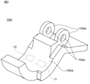
図1は、本発明の第1実施形態に係る非接触電圧測定装置の把持部材の側面図である。図2は、図1の把持部材のアームの斜視図である。図3は、本発明の第1実施形態に係る非接触電圧測定装置のブロック図である。
First Embodiment
Fig. 1 is a side view of a gripping member of a non-contact voltage measuring device according to a first embodiment of the present invention. Fig. 2 is a perspective view of an arm of the gripping member of Fig. 1. Fig. 3 is a block diagram of the non-contact voltage measuring device according to the first embodiment of the present invention.
非接触電圧測定装置1は、電線の導体の電圧を、当該導体とは非接触で測定する。第1実施形態において、非接触電圧測定装置1は、モータ4に接続された3相の電線2A,2B,2Cの導体2Aa,2Ba,2Ca(図3参照)の電圧を測定する。非接触電圧測定装置1の把持部材10が、3相の電線2A,2B,2Cのいずれかを把持する。非接触電圧測定装置1は、把持部材10が把持した電線の導体の電圧を測定する。図1では、把持部材10は、電線2Aを把持している。図3では、非接触電圧測定装置1は、電線2Aの導体2Aaの電圧を測定している。非接触電圧測定装置1によって測定された電圧は、表示部3に表示される。
The non-contact voltage measuring device 1 measures the voltage of the conductor of an electric wire without contacting the conductor. In the first embodiment, the non-contact voltage measuring device 1 measures the voltage of the conductors 2Aa, 2Ba, and 2Ca (see FIG. 3) of the three-phase
第1実施形態では、図3に示すように、電線2Aは、導体2Aaと、導体2Aaを覆う被覆部2Abとを備える。同様に、電線2Bは、導体2Baと、導体2Baを覆う被覆部2Bbとを備え、電線2Cは、導体2Caと、導体2Caを覆う被覆部2Cbとを備える。
In the first embodiment, as shown in FIG. 3, the
以下では、非接触電圧測定装置1が、3相の電線2A,2B,2Cのうちの電線2Aを把持して、電線2Aの導体2Aaの電圧を測定するものとして、説明が行われる。
The following description will be given assuming that the non-contact voltage measuring device 1 grasps the
図1~図3に示すように、非接触電圧測定装置1は、把持部材10と、装置本体20とを備える。図1に示すように、把持部材10は、電線2Aを把持する。図3に示すように、装置本体20は、把持部材10に接続される。
As shown in Figures 1 to 3, the non-contact voltage measuring device 1 includes a gripping
図1及び図2に示すように、把持部材10は、アーム10A,10Bを備える。アーム10A,10Bは、電線2Aを挟むことによって、電線2Aを把持する。
As shown in Figures 1 and 2, the gripping
アーム10Aは、面10Aaを有する。アーム10Bは、面10Baを有する。面10Aa,10Baは、互いに対向する。
図1に示すように、把持部材10を幅方向(以下、幅方向と記す。)から見て、面10Aaは、電線2Aを長手方向と直交に切断したときの断面を構成する円の円弧の形状である。幅方向は、把持部材10が電線2Aを把持するときの電線2Aの長手方向と平行である。幅方向(電線2Aの長手方向)は、図1の紙面奥行き方向と一致し、図3の紙面上下方向と一致する。
As shown in FIG. 1, when the gripping
図1に示すように、幅方向から見て、面10Baは、面10Aaと同様に、電線2Aを長手方向と直交に切断したときの断面を構成する円の円弧の形状である。
As shown in FIG. 1, when viewed from the width direction, surface 10Ba, like surface 10Aa, has the shape of an arc of a circle that constitutes a cross section when
これにより、アーム10A,10Bが電線2Aを把持したとき、面10Aa,10Baは、電線2Aの被覆部2Abの外周面に面接触する。なお、アーム10A,10Bは、電線2Aとは異なる直径の電線を把持することも可能である。この場合、面10Aa,10Baは、当該電線の被覆部の外周面に線接触する。
As a result, when the
図2に示すように、アーム10Aは、一対の軸支持部10Abを有する。一対の軸支持部10Abは幅方向に対向する。軸支持部10Abの各々は、軸支持部10Abを幅方向に貫通する貫通孔10Acを有する。
As shown in FIG. 2, the
図1に示すように、アーム10Bは、一対の軸支持部10Bbを有する。一対の軸支持部10Bbは、幅方向に対向する。図1では、一対の軸支持部10Bbのうちの一方のみが示される。一対の軸支持部10Bbは、幅方向の外側から一対の軸支持部10Abを挟む。一対の軸支持部10Bbの各々は、凹部(不図示)を有する。凹部は、軸支持部10Bbにおける軸支持部10Abを向く面に形成される。凹部は、幅方向に凹んでいる。アーム10Aの各貫通孔10Acと、アーム10Bの各凹部とは、幅方向に沿って一直線に並んでいる。
As shown in FIG. 1, the
シャフト(不図示)が、アーム10Aの各貫通孔10Acと、アーム10Bの各凹部とに挿通される。これにより、アーム10A,10Bは、互いに回動可能に支持される。つまり、アーム10Aはアーム10Bによって回転可能に支持され、アーム10Bはアーム10Aによって回転可能に支持される。
A shaft (not shown) is inserted through each through hole 10Ac of
ねじりコイルばね(不図示)が、一対の軸支持部10Abの間に配置される。ねじりコイルばねは、シャフトの周りに配置される。アーム10A,10Bは、ねじりコイルばねによって、把持部材10が閉じる方向に付勢される。これにより、電線2Aが、把持部材10によって把持された状態に保持される。
A torsion coil spring (not shown) is disposed between the pair of shaft support portions 10Ab. The torsion coil spring is disposed around the shaft. The
第1実施形態において、アーム10A,10Bは、互いに対向する。そのため、アーム10A,10Bの先端部が互いに接触すると、把持部材10はそれ以上閉じない。
In the first embodiment, the
図1及び図2に示すように、把持部材10のアーム10Aの内部に、2個の電極11,12が設けられる。電極11は、第1電極の一例である。電極11は、第2電極の一例である。図2に示すように、電極11,12は、幅方向に互いに離隔して並置される。電極11,12は、アーム10Aの面10Aaの裏側に配置される。
As shown in Figures 1 and 2, two
図3に示すように、把持部材10は、2個のコンデンサC1,C2を備える。コンデンサC1は、第1コンデンサの一例である。コンデンサC2は、第2コンデンサの一例である。第1実施形態において、コンデンサC1,C2は、アーム10Aの内部に設けられる。コンデンサC1は、電極11に接続される。コンデンサC2は、電極12に接続される。第1実施形態において、コンデンサC1の容量は、数pF~数十pFに設定される。コンデンサC2の容量は、コンデンサC1の容量の10倍~100倍に設定される。
As shown in FIG. 3, the gripping
前述したように、電極11,12はアーム10Aの内部に配置される。そのため、図1に示すように、把持部材10が電線2Aを把持するとき、電極11,12と電線2Aとの間に、アーム10Aがある。また、前述したように、電線2Aの導体2Aaは、被覆部2Abによって覆われる。そのため、把持部材10が電線2Aを把持するとき、電極11,12と電線2Aの導体2Aaとの間に、電線2Aの被覆部2Abがある。つまり、把持部材10が電線2Aを把持するとき、電極11,12と電線2Aの導体2Aaとの間に、アーム10Aと電線2Aの被覆部2Abとがある。すなわち、把持部材10が電線2Aを把持するとき、電極11,12は、電線2Aの導体2Aaと非接触である。
As described above, the
また、前述したように、電極11,12は、アーム10Aの面10Aaの裏側に配置される。そのため、把持部材10が電線2Aを把持するとき、電極11,12は、電線2Aの導体2Aaと電線2Aの径方向に対向する。
As described above, the
同様に、把持部材10が電線2Bを把持するとき、電極11,12は、電線2Bの導体2Baと非接触であり、電線2Bの導体2Baと電線2Bの径方向に対向する。また、把持部材10が電線2Cを把持するとき、電極11,12は、電線2Cの導体2Caと非接触であり、電線2Cの導体2Caと電線2Cの径方向に対向する。
Similarly, when the gripping
装置本体20は、直方体形状の筐体(不図示)と、増幅回路21,22と、演算部23とを備える。増幅回路21,22と演算部23とは、筐体の内部に配置される。なお、筐体の形状は、直方体に限らない。増幅回路21は、第1増幅回路の一例である。増幅回路22は、第2増幅回路の一例である。
The device
増幅回路21は、コンデンサC1に接続される。増幅回路21は、コンデンサC1と互いに直列に接続される。増幅回路22は、コンデンサC2に接続される。増幅回路22は、コンデンサC2と互いに直列に接続される。増幅回路21,22の構成は、後述される。
The
演算部23は、後述する演算を行う。演算部23は、様々な態様で実現可能である。例えば、演算部23は、メモリとCPU(Central Processing Unit)とを備えていてもよい。この場合、CPUが、メモリに記憶されたプログラムを実行することによって、後述する演算が実行される。また、例えば、演算部23は、後述する演算が実行可能な回路によって構成されてもよい。このような回路は、例えば、ASIC(Application Specific Integrated Circuit)、FPGA(Field Programmable Gate Array)等である。演算部23は、前述した構成が組み合わされて実現されてもよい。例えば、演算部23は、メモリと、CPUと、ASICとを備えていてもよい。
The
演算部23は、表示部3に接続される。表示部3は、LEDや液晶等複数を備えた公知のディスプレイである。表示部3は、電線2の導体の電圧を示す情報を演算部23から受け取り、電線2の導体の電圧値を、ユーザが認識可能な形式(例えば数字)で表示する。
The
図4は、本発明の第1実施形態に係る非接触電圧測定装置の等価回路図である。以下に、増幅回路21,22の構成と、演算部23が実行する演算とが説明される。
Figure 4 is an equivalent circuit diagram of the non-contact voltage measuring device according to the first embodiment of the present invention. The configuration of the
増幅回路21は、演算増幅器211と、コンデンサC3とを備える。コンデンサC3は、第3コンデンサの一例である。演算増幅器211の反転入力端子211Bに、コンデンサC1が接続される。演算増幅器211の非反転入力端子211Aは、グランドに接続される。コンデンサC3は、演算増幅器211の反転入力端子211Bと出力端子211Cとに接続される。言い換えると、コンデンサC3は、演算増幅器211の反転入力端子211Bと出力端子211Cとの間に接続される。増幅回路21の出力端子211Cは、演算部23と接続される。増幅回路21の出力端子211Cと演算部23との間は、検出電圧出力点212である。検出電圧出力点212の電圧は、言い換えると、増幅回路21の出力端子211Cの電圧である。
The
増幅回路22は、演算増幅器221と、コンデンサC4とを備える。コンデンサC4は、第4コンデンサの一例である。演算増幅器221の反転入力端子221Bに、コンデンサC2が接続される。演算増幅器221の非反転入力端子221Aは、グランドに接続される。コンデンサC4は、演算増幅器221の反転入力端子221Bと出力端子221Cとに接続される。言い換えると、コンデンサC4は、演算増幅器221の反転入力端子221Bと出力端子221Cとの間に接続される。増幅回路22の出力端子221Cは、演算部23と接続される。増幅回路22の出力端子221Cと演算部23との間は、検出電圧出力点222である。検出電圧出力点222の電圧は、言い換えると、増幅回路22の出力端子221Cの電圧である。
The
第1実施形態において、コンデンサC3の容量は、例えば、コンデンサC1の容量と同様に、数pF~数十pFに設定される。コンデンサC4の容量は、例えば、コンデンサC2の容量と同様に、コンデンサC3の容量の10倍~100倍に設定される。 In the first embodiment, the capacitance of the capacitor C3 is set to, for example, several pF to several tens of pF, similar to the capacitance of the capacitor C1 . The capacitance of the capacitor C4 is set to, for example, 10 to 100 times the capacitance of the capacitor C3 , similar to the capacitance of the capacitor C2 .
演算部23は、検出電圧出力点212,222から得た電圧と、予め設定されるコンデンサC1~C4の各々の容量とに基づいて、結合容量と、電線2Aの導体2Aaの電圧とを算出する。
The
結合容量は、容量結合している非接触電圧測定装置1と電線2Aとの間のうち、電極11と電線2Aの導体2Aaとの間、及び、電極12と電線2Aの導体2Aaとの間に存在する。つまり、図4に示すように、電極11と電線2Aの導体2Aaとの間に、コンデンサCL1が等価的に接続され、電極12と電線2Aの導体2Aaとの間に、コンデンサCL2が等価的に接続される。つまり、演算部23が算出する結合容量は、コンデンサCL1に蓄えられる容量と、コンデンサCL2に蓄えられる容量とを指す。コンデンサCL1に蓄えられる容量は、第1結合容量の一例である。コンデンサCL2に蓄えられる容量は、第2結合容量の一例である。
The coupling capacitance exists between the
演算部23は、以下の式(1)~式(6)を用いて、電極11と電線2Aの導体2Aaとの間の結合容量、電極12と電線2Aの導体2Aaとの間の結合容量、及び電線2Aの導体2Aaの電圧を算出する。なお、演算部23は、前記の結合容量を算出しなくてもよい。つまり、演算部23は、少なくとも電線2Aの導体2Aaの電圧を算出すればよい。
The
Z1=(CL1+C1)/jωCL1C1 ・・・(1)
Z2=(CL2+C2)/jωCL2C2 ・・・(2)
Z3=1/jωC3 ・・・(3)
Z4=1/jωC4 ・・・(4)
V1=-(Z3/Z1)VL ・・・(5)
V2=-(Z4/Z2)VL ・・・(6)
Z 1 = (C L1 + C 1 )/jωC L1 C 1 ...(1)
Z 2 = (C L2 + C 2 )/jωC L2 C 2 ...(2)
Z 3 = 1/jωC 3 ...(3)
Z 4 = 1/jωC 4 ...(4)
V 1 =-(Z 3 /Z 1 )V L ...(5)
V 2 =-(Z 4 /Z 2 )V L ...(6)
前述の式(1)~式(4)において、「C」を含む各記号の意味は、以下の通りである。CL1は、電極11と電線2Aの導体2Aaとの間の結合容量(コンデンサCL1に蓄えられる容量)である。CL2は、電極12と電線2Aの導体2Aaとの間の結合容量(コンデンサCL2に蓄えられる容量)である。C1は、コンデンサC1の容量である。C2は、コンデンサC2の容量である。C3は、コンデンサC3の容量である。C4は、コンデンサC4の容量である。
In the above formulas (1) to (4), the meanings of the symbols including "C" are as follows: C L1 is the coupling capacitance between the
前述の式(1)~式(6)において、「Z」を含む各記号の意味は、以下の通りである。Z1は、コンデンサCL1とコンデンサC1との合成インピーダンスである。Z2は、コンデンサCL2とコンデンサC2との合成インピーダンスである。Z3は、コンデンサC3のインピーダンスである。Z4は、コンデンサC4のインピーダンスである。 In the above formulas (1) to (6), the meanings of the symbols including "Z" are as follows: Z1 is the composite impedance of capacitors C L1 and C 1. Z2 is the composite impedance of capacitors C L2 and C 2. Z3 is the impedance of capacitor C3 . Z4 is the impedance of capacitor C4 .
前述の式(5)及び式(6)において、「V」を含む各記号の意味は、以下の通りである。V1は、検出電圧出力点212の電圧、つまり増幅回路21の出力端子211Cの電圧である。V2は、検出電圧出力点222の電圧、つまり増幅回路22の出力端子221Cの電圧である。VLは、電線2Aの導体2Aaの電圧である。なお、式(5)、(6)は、反転増幅回路である増幅回路21,22における入力電圧と出力電圧との関係式である。
In the above-mentioned formulas (5) and (6), the meanings of the symbols including "V" are as follows: V1 is the voltage at the detection
式(1)及び式(2)が式(5)に代入され、式(3)及び式(4)が式(6)に代入される。また、第1実施形態では、CL1=CL2=CLとされる。CLは、非接触電圧測定装置1と電線2Aとの間に存在する結合容量である。これにより、未知の値がCLとVLである二次元連立方程式が導出される。この二次元連立方程式を解くことによって、以下の式(7)及び式(8)が導出される。
Equations (1) and (2) are substituted into equation (5), and equations (3) and (4) are substituted into equation (6). In the first embodiment, C L1 =C L2 =C L. C L is the coupling capacitance that exists between the non-contact voltage measuring device 1 and the
CL=-(C1C2C4V2-C1C2C3V1)/(C1C4V2-C2C3V1)
・・・(7)
VL=-((C2-C1)C3C4V1V2)/(C1C2C4V2-C1C2C3V1)
・・・(8)
C L =-(C 1 C 2 C 4 V 2 - C 1 C 2 C 3 V 1 )/(C 1 C 4 V 2 - C 2 C 3 V 1 )
...(7)
V L =-((C 2 -C 1 )C 3 C 4 V 1 V 2 )/(C 1 C 2 C 4 V 2 -C 1 C 2 C 3 V 1 )
...(8)
式(7)及び式(8)の右辺は、全て既知の値である。そのため、式(7)より結合容量CLが算出され、式(8)より電線2Aの導体2Aaの電圧VLが算出される。
The right-hand sides of equations (7) and (8) are all known values. Therefore, the coupling capacitance C L is calculated from equation (7), and the voltage V L of the conductor 2Aa of the
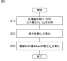
図5は、電線の導体の電圧を測定する過程を示すフローチャートである。以下、図5を参照しつつ、演算部23が、電線2Aの導体2Aaの電圧VLと、非接触電圧測定装置1と電線2Aとの間に存在する結合容量CLとを算出する手順が説明される。
5 is a flowchart showing a process for measuring the voltage of the conductor of an electric wire. Hereinafter, a procedure in which the
最初に、演算部23は、以下のようにして、各増幅回路21,22の電圧V1,V2を計測する(S10)。モータ4に電力を供給するために、3相の電線2A,2B,2Cに電圧が印加されると、コンデンサCL1、コンデンサC1、増幅回路21を介して検出電圧出力点212に電圧V1が印加される。また、コンデンサCL2、コンデンサC2、増幅回路22を介して検出電圧出力点222に電圧V2が印加される。演算部23は、これらの電圧V1,V2を取得する。
First, the
次に、演算部23は、式(7)によって結合容量CLを算出する(S20)。次に、演算部23は、式(8)によって電線2Aの導体2Aaの電圧VLを算出する(S30)。なお、ステップS20,S30の実行順序は逆でもよいし、ステップS20,S30が並行して実行されてもよい。
Next, the
第1実施形態によれば、演算部23による電線2Aの導体2Aaの電圧の算出過程において、周波数の項を消すことができる。これにより、フーリエ変換等を用いた複雑な演算を行うことなく、電線2Aの導体2Aaの電圧を算出することができる。つまり、従来技術より簡単な演算で、複数の周波数成分を含む電圧の測定を行うことができる。
According to the first embodiment, the frequency term can be eliminated in the process of calculating the voltage of the conductor 2Aa of the
第1実施形態によれば、電極11と電線2Aの導体2Aaとの間の結合容量と、電極12と電線2Aの導体2Aaとの間の結合容量とを常時求めることができる。そのため、温度及び湿度の変化、電線の経年劣化等の環境変化による結合容量の変化にリアルタイムで対応することができる。
According to the first embodiment, the coupling capacitance between the
第1実施形態によれば、演算部23は、電線2Aの導体2Aaの電圧と同様にして、コンデンサC1,C2,C3,C4の容量、増幅回路21の出力端子211Cの電圧、及び増幅回路22の出力端子221Cの電圧に基づいて、結合容量CL1,CL2を算出することができる。
According to the first embodiment, the
第1実施形態では、CL1=CL2=CLとされる。これにより、結合容量CL1と結合容量CL2とを簡単な演算で算出することができる。 In the first embodiment, C L1 =C L2 =C L. This allows the coupling capacitances C L1 and C L2 to be calculated by a simple calculation.
第1実施形態によれば、CL1とCL2との関係が規定されることにより、例えばCL1=CL2と規定されることにより、式(1)及び式(3)が代入された式(5)と、式(2)及び式(4)が代入された式(6)との連立方程式が導出される。この連立方程式を解くことによって、結合容量CL1、結合容量CL2、及び電線の導体の電圧VLを算出することができる。前記の連立方程式を解く過程において、ωの項(周波数の項)が消える。これにより、フーリエ変換等を用いた複雑な演算を行うことなく、当該連立方程式を解くことができる。つまり、従来技術より簡単な演算で、複数の周波数成分を含む電圧の測定を行うことができる。 According to the first embodiment, by defining the relationship between C L1 and C L2 , for example, by defining C L1 =C L2 , simultaneous equations are derived, which are the equation (5) into which the equations (1) and (3) are substituted, and the equation (6) into which the equations (2) and (4) are substituted. By solving this simultaneous equation, the coupling capacitance C L1 , the coupling capacitance C L2 , and the voltage V L of the conductor of the electric wire can be calculated. In the process of solving the simultaneous equations, the ω term (frequency term) disappears. This makes it possible to solve the simultaneous equations without performing complex calculations using Fourier transforms or the like. In other words, it is possible to measure a voltage including multiple frequency components with calculations simpler than those of the prior art.
第1実施形態によれば、把持部材10が電線2Aを把持することによって、電線2Aの導体2Aaの電圧を算出することができる。
According to the first embodiment, the gripping
第1実施形態によれば、結合容量CL1と結合容量CL2とを同一または略同一とすることができる。 According to the first embodiment, the coupling capacitance C L1 and the coupling capacitance C L2 can be made the same or approximately the same.
第1実施形態では、電極11,12及びコンデンサC1,C2は、把持部材10のアーム10Aの内部に設けられる。しかし、電極11,12及びコンデンサC1,C2は、把持部材10のアーム10Bの内部に設けられてもよい。この場合、電極11,12は、例えば、アーム10Bの面10Baの裏側に配置される。
In the first embodiment, the
第1実施形態では、電線2Aは、導体2Aaと、導体2Aaを覆う被覆部2Abとを備える。しかし、電線2Aは、被覆部2Abを備えていなくてもよい。この場合、電線2Aの導体2Aaは、外部に剥き出しである。しかし、第1実施形態では、電極11,12は、把持部材10のアーム10Aの内部に設けられる。そのため、把持部材10が電線2Aを把持するとき、電極11,12と電線2Aの導体2Aaとの間に、アーム10Aがある。よって、この場合であっても、把持部材10が電線2Aを把持するとき、電極11,12は、電線2Aの導体2Aaと非接触である。なお、電線2B,2Cも、それぞれ被覆部2Bb,2Cbを備えていなくてもよい。
In the first embodiment, the
第1実施形態では、電極11,12は、把持部材10のアーム10Aの内部に設けられる。しかし、電極11,12は、アーム10Aの外部に設けられてもよい。例えば、電極11,12は、アーム10Aの面10Aaに設けられてもよい。この場合、電極11,12は外部に剥き出しである。しかし、第1実施形態では、電線2A,2B,2Cの各々は、被覆部2Ab,2Bb,2Cbを備える。そのため、例えば、把持部材10が電線2Aを把持するとき、電極11,12と電線2Aの導体2Aaとの間に、電線2Aの被覆部2Abがある。よって、この場合であっても、把持部材10が電線2Aを把持するとき、電極11,12は、電線2Aの導体2Aaと非接触である。
In the first embodiment, the
非接触電圧測定装置1は、把持部材10を備えていなくてもよい。この場合、例えば、非接触電圧測定装置1によって電線2A,2B,2Cの導体2Aa,2Ba,2Caの電圧が測定されるときに、剥き出しの電極11,12が、電線2A,2B,2Cの被覆部2Ab,2Bb,2Cbの外周面に貼り付けられる。
The non-contact voltage measuring device 1 does not have to include the gripping
第1実施形態では、非接触電圧測定装置1は把持部材10と装置本体20とを備え、把持部材10の内部にコンデンサC1,C2が設けられ、装置本体20の内部に増幅回路21,22及び演算部23が設けられる。しかし、非接触電圧測定装置1は、前述のような構成に限らない。例えば、コンデンサC1,C2が把持部材10の内部ではなく、装置本体20の内部に設けられてもよい。また、例えば、増幅回路21,22が装置本体20の内部ではなく、把持部材10の内部に設けられてもよい。また、例えば、把持部材10と装置本体20とが一体に構成されていてもよい。
In the first embodiment, the non-contact voltage measuring device 1 includes a gripping
第1実施形態では、非接触電圧測定装置1のコンデンサC1,C2及び演算増幅器211,221は、図4に示すような回路構成であるが、図4に示すような回路構成に限らない。
In the first embodiment, the capacitors C 1 and C 2 and the
例えば、コンデンサC1,C3が非反転入力端子211Aに接続され、コンデンサC2,C4が非反転入力端子221Aに接続され、反転入力端子211B,221Bがグランドに接続されていてもよい。また、例えば、コンデンサC1,C3が反転入力端子211Bに接続され、コンデンサC2,C4が非反転入力端子221Aに接続され、非反転入力端子211A及び反転入力端子221Bがグランドに接続されていてもよい。また、例えば、コンデンサC1,C3が非反転入力端子211Aに接続され、コンデンサC2,C4が反転入力端子221Bに接続され、反転入力端子211B及び非反転入力端子221Aがグランドに接続されていてもよい。
For example, the capacitors C1 and C3 may be connected to the
第1実施形態では、CL1=CL2=CLと規定されることによって、式(7)及び式(8)よりなる連立方程式が導出される。しかし、結合容量CL1と結合容量CL2とは、等しくないと規定されてもよい。例えば、CL1+ΔCL1=CL2とされてもよい。つまり、演算部23は、結合容量CL1と結合容量CL2との差が一定であるとして、結合容量CL1と結合容量CL2とを算出してもよい。この場合であっても、前述した式によって結合容量CL1,CL2を算出することができる。
In the first embodiment, by defining C L1 =C L2 =C L , a simultaneous equation consisting of equations (7) and (8) is derived. However, the coupling capacitances C L1 and C L2 may be defined as not being equal. For example, C L1 +ΔC L1 =C L2 may be defined. That is, the
この場合、結合容量CL1と結合容量CL2とが等しくない場合であっても、結合容量CL1と結合容量CL2とを算出することができる。 In this case, even if the coupling capacitances C L1 and C L2 are not equal, the coupling capacitances C L1 and C L2 can be calculated.
<第2実施形態>
図6は、本発明の第2実施形態に係る非接触電圧測定装置の把持部材の正面図である。第2実施形態に係る非接触電圧測定装置が第1実施形態に係る非接触電圧測定装置と異なることは、把持部材101における電極11,12の配置である。以下、第1実施形態と相違する構成が説明される。第1実施形態の非接触電圧測定装置と共通する構成については、同一の符号が付された上で、その説明は原則省略され、必要に応じて説明される。これは、後述する第3実施形態においても同様である。
Second Embodiment
6 is a front view of a gripping member of a non-contact voltage measuring device according to a second embodiment of the present invention. The non-contact voltage measuring device according to the second embodiment differs from the non-contact voltage measuring device according to the first embodiment in the arrangement of
把持部材101は、第1実施形態の把持部材10と同様に、内部に電極11,12を有する。第2実施形態では、図6に示すように、電極11はアーム10Aの内部に設けられ、電極12はアーム10Bの内部に設けられる。電極11,12は、把持部材101が電線2Aを把持するときに、電線2Aの中心軸AXを挟んで互いに対向する位置に配置される。
The gripping
第2実施形態によれば、結合容量CL1と結合容量CL2とを同一または略同一とすることができる。 According to the second embodiment, the coupling capacitance C L1 and the coupling capacitance C L2 can be made the same or approximately the same.
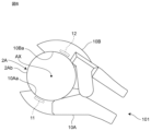
<第3実施形態>
図7は、本発明の第3実施形態に係る非接触電圧測定装置の把持部材の斜視図である。第3実施形態に係る非接触電圧測定装置が第1実施形態に係る非接触電圧測定装置と異なることは、把持部材102において、アーム10A,10Bが互いに対向していないことである。以下、第1実施形態と相違する構成が説明される。
Third Embodiment
7 is a perspective view of a gripping member of a non-contact voltage measuring device according to a third embodiment of the present invention. The non-contact voltage measuring device according to the third embodiment differs from the non-contact voltage measuring device according to the first embodiment in that the
図7に示すように、把持部材102は、図1に示すアーム10Bの代わりにアーム10Cを備える。
As shown in FIG. 7, the gripping
アーム10Cは、一対の突出部10CAを備える。一対の突出部10CAは、互いに幅方向に対向する。一対の突出部10CAは、アーム10Aを幅方向に挟む位置に形成される。アーム10Aと一対の突出部10CAとは、電線2Aを挟むことによって、電線2Aを把持する。一対の突出部10CAは、アーム10Aと対向していない。一対の突出部10CAの各々は、面10Caを有する。面10Caは、アーム10Aの面10Aaと対向していない。
The
アーム10Cは、一対の軸支持部10Cbを有する。図7では、一対の軸支持部10Cbのうちの一方のみが示される。一対の軸支持部10Cbは、幅方向に対向する。一対の軸支持部10Cbは、幅方向の外側から一対の軸支持部10Abを挟む。一対の軸支持部10Cbの各々は、貫通孔10Ccを有する。アーム10Aの各貫通孔10Acと、アーム10Cの各貫通孔10Ccとは、幅方向に沿って一直線に並んでいる。これにより、第1実施形態と同様に、アーム10A,10Cは、互いに回動可能に支持される。
The
第1実施形態では、アーム10A,10Bは、互いに対向する。そのため、アーム10A,10Bの先端部が互いに接触すると、把持部材10はそれ以上閉じない。これに対して、第3実施形態では、一対の突出部10CAは、アーム10Aと対向していない。そのため、把持部材102の一対の突出部10CAは、第1実施形態の把持部材10のアーム10Bより、アーム10Aに近づくまで閉じることができる。その結果、第3実施形態に係る非接触電圧測定装置の把持部材102は、第1実施形態に係る非接触電圧測定装置1の把持部材10より細い電線2を把持することができる。
In the first embodiment, the
1 非接触電圧測定装置
2A 電線
2B 電線
2C 電線
10 把持部材
11 電極(第1電極)
12 電極(第2電極)
21 増幅回路(第1増幅回路)
211B 反転入力端子
211C 出力端子
22 増幅回路(第2増幅回路)
221B 反転入力端子
221C 出力端子
23 演算部
C1 コンデンサ(第1コンデンサ)
C2 コンデンサ(第2コンデンサ)
C3 コンデンサ(第3コンデンサ)
C4 コンデンサ(第4コンデンサ)
REFERENCE SIGNS LIST 1 Non-contact
12 electrode (second electrode)
21 Amplification circuit (first amplification circuit)
211B: inverting
221B: inverting
C2 capacitor (second capacitor)
C3 capacitor (third capacitor)
C4 capacitor (fourth capacitor)
Claims (8)
前記第1電極と接続される第1コンデンサと、
前記第1コンデンサと互いに直列に接続される第1増幅回路と、
前記第2電極と接続される第2コンデンサと、
前記第2コンデンサと互いに直列に接続される第2増幅回路と、
演算部と、を備え、
前記第1電極及び前記第2電極の各々は、電線の導体と非接触で且つ前記電線の導体と対向し、
前記第1コンデンサは、前記第1増幅回路の入力端子である第1入力端子に接続され、
前記第2コンデンサは、前記第2増幅回路の入力端子である第2入力端子に接続され、
前記第1増幅回路は、前記第1増幅回路の出力端子である第1出力端子と前記第1入力端子との間に接続される第3コンデンサを備え、
前記第2増幅回路は、前記第2増幅回路の出力端子である第2出力端子と前記第2入力端子との間に接続される第4コンデンサを備え、
前記演算部は、
前記第1コンデンサの容量、前記第2コンデンサの容量、前記第3コンデンサの容量、前記第4コンデンサの容量、前記第1出力端子の電圧、及び前記第2出力端子の電圧に基づいて、前記電線の導体の電圧を算出する非接触電圧測定装置。 a first electrode and a second electrode spaced apart from each other;
a first capacitor connected to the first electrode;
a first amplifier circuit connected in series with the first capacitor;
a second capacitor connected to the second electrode;
a second amplifier circuit connected in series with the second capacitor;
A calculation unit,
each of the first electrode and the second electrode faces a conductor of the electric wire without being in contact with the conductor of the electric wire;
the first capacitor is connected to a first input terminal which is an input terminal of the first amplifier circuit;
the second capacitor is connected to a second input terminal which is an input terminal of the second amplifier circuit;
the first amplifier circuit includes a third capacitor connected between a first output terminal that is an output terminal of the first amplifier circuit and the first input terminal;
the second amplifier circuit includes a fourth capacitor connected between a second output terminal that is an output terminal of the second amplifier circuit and the second input terminal;
The calculation unit is
A non-contact voltage measuring device that calculates the voltage of the conductor of the electric wire based on the capacitance of the first capacitor, the capacitance of the second capacitor, the capacitance of the third capacitor, the capacitance of the fourth capacitor, the voltage of the first output terminal , and the voltage of the second output terminal.
Z1=(CL1+C1)/jωCL1C1・・・(1)
Z2=(CL2+C2)/jωCL2C2・・・(2)
Z3=1/jωC3・・・(3)
Z4=1/jωC4・・・(4)
V1=-(Z3/Z1)VL・・・(5)
V2=-(Z4/Z2)VL・・・(6)
ここで、
CL1は、前記第1電極と前記電線の導体との間の第1結合容量であり、
CL2は、前記第2電極と前記電線の導体との間の第2結合容量であり、
C1は、前記第1コンデンサの容量であり、
C2は、前記第2コンデンサの容量であり、
C3は、前記第3コンデンサの容量であり、
C4は、前記第4コンデンサの容量であり、
Z1は、前記第1結合容量を蓄えるコンデンサと前記第1コンデンサとの合成インピーダンスであり、
Z2は、前記第2結合容量を蓄えるコンデンサと前記第2コンデンサとの合成インピーダンスであり、
Z3は、前記第3コンデンサのインピーダンスであり、
Z4は、前記第4コンデンサのインピーダンスであり、
V1は、前記第1出力端子の電圧であり、
V2は、前記第2出力端子の電圧であり、
VLは、前記電線の導体の電圧であり、
前記電線の導体の電圧を算出する請求項1から4のいずれか1項に記載の非接触電圧測定装置。 The calculation unit uses the following formulas (1) to (6):
Z 1 = (C L1 + C 1 )/jωC L1 C 1 ...(1)
Z 2 = (C L2 + C 2 )/jωC L2 C 2 ...(2)
Z 3 = 1/jωC 3 ...(3)
Z 4 = 1/jωC 4 ...(4)
V 1 =-(Z 3 /Z 1 )V L ...(5)
V 2 =-(Z 4 /Z 2 )V L ...(6)
Where:
C L1 is a first coupling capacitance between the first electrode and the conductor of the wire;
C L2 is a second coupling capacitance between the second electrode and the wire conductor;
C1 is the capacitance of the first capacitor;
C2 is the capacitance of the second capacitor;
C3 is the capacitance of the third capacitor;
C4 is the capacitance of the fourth capacitor;
Z1 is a composite impedance of the capacitor storing the first coupling capacitance and the first capacitor,
Z2 is a composite impedance of the capacitor storing the second coupling capacitance and the second capacitor,
Z3 is the impedance of the third capacitor;
Z4 is the impedance of the fourth capacitor;
V1 is the voltage at the first output terminal ;
V2 is the voltage at the second output terminal ;
VL is the voltage of the conductor of the wire;
The non-contact voltage measuring device according to claim 1 , further comprising a conductor for calculating a voltage of the electric wire.
前記第1電極及び前記第2電極は、前記把持部材に設けられ、
前記第1電極及び前記第2電極の各々は、前記把持部材が前記電線を把持するときに、前記電線の導体と対向する請求項1から5のいずれか1項に記載の非接触電圧測定装置。 The non-contact voltage measuring device further includes a gripping member that grips the electric wire,
The first electrode and the second electrode are provided on the gripping member,
The non-contact voltage measurement device according to claim 1 , wherein each of the first electrode and the second electrode faces a conductor of the electric wire when the gripping member grips the electric wire.
Priority Applications (2)
| Application Number | Priority Date | Filing Date | Title |
|---|---|---|---|
| JP2021039429A JP7608887B2 (en) | 2021-03-11 | 2021-03-11 | Non-contact voltage measuring device |
| PCT/JP2022/002524 WO2022190678A1 (en) | 2021-03-11 | 2022-01-25 | Non-contact voltage measurement device |
Applications Claiming Priority (1)
| Application Number | Priority Date | Filing Date | Title |
|---|---|---|---|
| JP2021039429A JP7608887B2 (en) | 2021-03-11 | 2021-03-11 | Non-contact voltage measuring device |
Publications (2)
| Publication Number | Publication Date |
|---|---|
| JP2022139167A JP2022139167A (en) | 2022-09-26 |
| JP7608887B2 true JP7608887B2 (en) | 2025-01-07 |
Family
ID=83226691
Family Applications (1)
| Application Number | Title | Priority Date | Filing Date |
|---|---|---|---|
| JP2021039429A Active JP7608887B2 (en) | 2021-03-11 | 2021-03-11 | Non-contact voltage measuring device |
Country Status (2)
| Country | Link |
|---|---|
| JP (1) | JP7608887B2 (en) |
| WO (1) | WO2022190678A1 (en) |
Citations (9)
| Publication number | Priority date | Publication date | Assignee | Title |
|---|---|---|---|---|
| JP2012215558A (en) | 2011-03-30 | 2012-11-08 | Denso Corp | Voltage detector and coupling circuit |
| JP2015175655A (en) | 2014-03-13 | 2015-10-05 | オムロン株式会社 | Noncontact voltage measuring apparatus |
| WO2016175123A1 (en) | 2015-04-28 | 2016-11-03 | アルプス・グリーンデバイス株式会社 | Non-contact voltage measurement device |
| JP2019032175A (en) | 2017-08-04 | 2019-02-28 | 株式会社デンソー | Voltage detector |
| JP2019078677A (en) | 2017-10-26 | 2019-05-23 | 大崎電気工業株式会社 | Voltage measurement device |
| JP2019114901A (en) | 2017-12-22 | 2019-07-11 | ルネサスエレクトロニクス株式会社 | Semiconductor device and sensor system |
| JP2020144026A (en) | 2019-03-07 | 2020-09-10 | 株式会社関電工 | Insulated voltage measurement device |
| CN211905516U (en) | 2020-02-17 | 2020-11-10 | 南方电网科学研究院有限责任公司 | Non-contact voltage measuring device |
| CN112394846A (en) | 2019-08-16 | 2021-02-23 | 瑞尼斯股份有限公司 | Touch input detection device |
Family Cites Families (2)
| Publication number | Priority date | Publication date | Assignee | Title |
|---|---|---|---|---|
| JP2019032179A (en) * | 2017-08-04 | 2019-02-28 | 株式会社エム・アンド・ジェイ | Measuring method of blade |
| JP7101152B2 (en) * | 2019-09-06 | 2022-07-14 | 株式会社東芝 | Electronic circuits, current measuring devices, and methods |
-
2021
- 2021-03-11 JP JP2021039429A patent/JP7608887B2/en active Active
-
2022
- 2022-01-25 WO PCT/JP2022/002524 patent/WO2022190678A1/en not_active Ceased
Patent Citations (9)
| Publication number | Priority date | Publication date | Assignee | Title |
|---|---|---|---|---|
| JP2012215558A (en) | 2011-03-30 | 2012-11-08 | Denso Corp | Voltage detector and coupling circuit |
| JP2015175655A (en) | 2014-03-13 | 2015-10-05 | オムロン株式会社 | Noncontact voltage measuring apparatus |
| WO2016175123A1 (en) | 2015-04-28 | 2016-11-03 | アルプス・グリーンデバイス株式会社 | Non-contact voltage measurement device |
| JP2019032175A (en) | 2017-08-04 | 2019-02-28 | 株式会社デンソー | Voltage detector |
| JP2019078677A (en) | 2017-10-26 | 2019-05-23 | 大崎電気工業株式会社 | Voltage measurement device |
| JP2019114901A (en) | 2017-12-22 | 2019-07-11 | ルネサスエレクトロニクス株式会社 | Semiconductor device and sensor system |
| JP2020144026A (en) | 2019-03-07 | 2020-09-10 | 株式会社関電工 | Insulated voltage measurement device |
| CN112394846A (en) | 2019-08-16 | 2021-02-23 | 瑞尼斯股份有限公司 | Touch input detection device |
| CN211905516U (en) | 2020-02-17 | 2020-11-10 | 南方电网科学研究院有限责任公司 | Non-contact voltage measuring device |
Also Published As
| Publication number | Publication date |
|---|---|
| JP2022139167A (en) | 2022-09-26 |
| WO2022190678A1 (en) | 2022-09-15 |
Similar Documents
| Publication | Publication Date | Title |
|---|---|---|
| EP2057475A1 (en) | A method for measuring the electrical conductivity of solutions | |
| KR20230066595A (en) | Non-contact electrical parameter measuring device with dual radially mounted sensors | |
| CN106133532B (en) | Clamp Ammeter | |
| CN108072782A (en) | Non-contact voltage measuring system | |
| WO2015137017A1 (en) | Non-contact voltage measurement device | |
| WO2017168608A1 (en) | Contactless voltage measurement device and contactless voltage measurement method | |
| JP2003028900A (en) | Non-contact voltage measuring method and device | |
| JP7608887B2 (en) | Non-contact voltage measuring device | |
| WO2020095471A1 (en) | Impedance measurement device | |
| JP3469586B2 (en) | Impedance-voltage conversion device and conversion method | |
| JP4251961B2 (en) | Non-contact voltage measuring device | |
| Bera et al. | A modified Schering bridge for measurement of the dielectric parameters of a material and the capacitance of a capacitive transducer | |
| JP3815771B2 (en) | Capacitance type gap sensor and signal detection method thereof | |
| JP5322391B2 (en) | Voltage phase detection terminal | |
| JP5866890B2 (en) | Eddy current detection method and eddy current detection apparatus | |
| WO2015133212A1 (en) | Voltage measuring apparatus and voltage measuring method | |
| JP2005156492A (en) | Movable mechanism, measuring device, capacitive distance measuring device, and positioning device | |
| CN213336542U (en) | Temperature sensing device | |
| JP4208560B2 (en) | Impedance measuring device | |
| JP2655886B2 (en) | Laser processing machine nozzle distance detection device | |
| JP2003156551A (en) | Capacitance meter calibration method, calibration standard capacitance box, capacitance measurement method, capacitance measurement box and capacitance meter | |
| JP2019078677A (en) | Voltage measurement device | |
| JP2975389B2 (en) | Circuit element measuring device | |
| CN112505421A (en) | Measuring circuit for direct current resistance of dry-type air-core reactor | |
| JP3757226B2 (en) | Carrier type 3-wire strain measurement system |
Legal Events
| Date | Code | Title | Description |
|---|---|---|---|
| A621 | Written request for application examination |
Free format text: JAPANESE INTERMEDIATE CODE: A621 Effective date: 20240116 |
|
| A131 | Notification of reasons for refusal |
Free format text: JAPANESE INTERMEDIATE CODE: A131 Effective date: 20241008 |
|
| A521 | Request for written amendment filed |
Free format text: JAPANESE INTERMEDIATE CODE: A523 Effective date: 20241111 |
|
| TRDD | Decision of grant or rejection written | ||
| A01 | Written decision to grant a patent or to grant a registration (utility model) |
Free format text: JAPANESE INTERMEDIATE CODE: A01 Effective date: 20241119 |
|
| A61 | First payment of annual fees (during grant procedure) |
Free format text: JAPANESE INTERMEDIATE CODE: A61 Effective date: 20241202 |
|
| R150 | Certificate of patent or registration of utility model |
Ref document number: 7608887 Country of ref document: JP Free format text: JAPANESE INTERMEDIATE CODE: R150 |