JP7608874B2 - Display device, display method, and program - Google Patents
Display device, display method, and program Download PDFInfo
- Publication number
- JP7608874B2 JP7608874B2 JP2021033451A JP2021033451A JP7608874B2 JP 7608874 B2 JP7608874 B2 JP 7608874B2 JP 2021033451 A JP2021033451 A JP 2021033451A JP 2021033451 A JP2021033451 A JP 2021033451A JP 7608874 B2 JP7608874 B2 JP 7608874B2
- Authority
- JP
- Japan
- Prior art keywords
- row
- column
- selection
- display device
- handwritten data
- Prior art date
- Legal status (The legal status is an assumption and is not a legal conclusion. Google has not performed a legal analysis and makes no representation as to the accuracy of the status listed.)
- Active
Links
Images


Classifications
-
- G—PHYSICS
- G06—COMPUTING OR CALCULATING; COUNTING
- G06F—ELECTRIC DIGITAL DATA PROCESSING
- G06F3/00—Input arrangements for transferring data to be processed into a form capable of being handled by the computer; Output arrangements for transferring data from processing unit to output unit, e.g. interface arrangements
- G06F3/01—Input arrangements or combined input and output arrangements for interaction between user and computer
- G06F3/048—Interaction techniques based on graphical user interfaces [GUI]
- G06F3/0481—Interaction techniques based on graphical user interfaces [GUI] based on specific properties of the displayed interaction object or a metaphor-based environment, e.g. interaction with desktop elements like windows or icons, or assisted by a cursor's changing behaviour or appearance
- G06F3/0482—Interaction with lists of selectable items, e.g. menus
-
- G—PHYSICS
- G06—COMPUTING OR CALCULATING; COUNTING
- G06F—ELECTRIC DIGITAL DATA PROCESSING
- G06F3/00—Input arrangements for transferring data to be processed into a form capable of being handled by the computer; Output arrangements for transferring data from processing unit to output unit, e.g. interface arrangements
- G06F3/01—Input arrangements or combined input and output arrangements for interaction between user and computer
- G06F3/048—Interaction techniques based on graphical user interfaces [GUI]
- G06F3/0484—Interaction techniques based on graphical user interfaces [GUI] for the control of specific functions or operations, e.g. selecting or manipulating an object, an image or a displayed text element, setting a parameter value or selecting a range
- G06F3/04842—Selection of displayed objects or displayed text elements
-
- G—PHYSICS
- G06—COMPUTING OR CALCULATING; COUNTING
- G06F—ELECTRIC DIGITAL DATA PROCESSING
- G06F3/00—Input arrangements for transferring data to be processed into a form capable of being handled by the computer; Output arrangements for transferring data from processing unit to output unit, e.g. interface arrangements
- G06F3/01—Input arrangements or combined input and output arrangements for interaction between user and computer
- G06F3/048—Interaction techniques based on graphical user interfaces [GUI]
- G06F3/0487—Interaction techniques based on graphical user interfaces [GUI] using specific features provided by the input device, e.g. functions controlled by the rotation of a mouse with dual sensing arrangements, or of the nature of the input device, e.g. tap gestures based on pressure sensed by a digitiser
- G06F3/0488—Interaction techniques based on graphical user interfaces [GUI] using specific features provided by the input device, e.g. functions controlled by the rotation of a mouse with dual sensing arrangements, or of the nature of the input device, e.g. tap gestures based on pressure sensed by a digitiser using a touch-screen or digitiser, e.g. input of commands through traced gestures
- G06F3/04883—Interaction techniques based on graphical user interfaces [GUI] using specific features provided by the input device, e.g. functions controlled by the rotation of a mouse with dual sensing arrangements, or of the nature of the input device, e.g. tap gestures based on pressure sensed by a digitiser using a touch-screen or digitiser, e.g. input of commands through traced gestures for inputting data by handwriting, e.g. gesture or text
-
- G—PHYSICS
- G06—COMPUTING OR CALCULATING; COUNTING
- G06V—IMAGE OR VIDEO RECOGNITION OR UNDERSTANDING
- G06V10/00—Arrangements for image or video recognition or understanding
- G06V10/20—Image preprocessing
- G06V10/22—Image preprocessing by selection of a specific region containing or referencing a pattern; Locating or processing of specific regions to guide the detection or recognition
- G06V10/235—Image preprocessing by selection of a specific region containing or referencing a pattern; Locating or processing of specific regions to guide the detection or recognition based on user input or interaction
-
- G—PHYSICS
- G06—COMPUTING OR CALCULATING; COUNTING
- G06V—IMAGE OR VIDEO RECOGNITION OR UNDERSTANDING
- G06V30/00—Character recognition; Recognising digital ink; Document-oriented image-based pattern recognition
- G06V30/10—Character recognition
- G06V30/14—Image acquisition
- G06V30/142—Image acquisition using hand-held instruments; Constructional details of the instruments
- G06V30/1423—Image acquisition using hand-held instruments; Constructional details of the instruments the instrument generating sequences of position coordinates corresponding to handwriting
-
- G—PHYSICS
- G06—COMPUTING OR CALCULATING; COUNTING
- G06F—ELECTRIC DIGITAL DATA PROCESSING
- G06F2203/00—Indexing scheme relating to G06F3/00 - G06F3/048
- G06F2203/048—Indexing scheme relating to G06F3/048
- G06F2203/04807—Pen manipulated menu
Landscapes
- Engineering & Computer Science (AREA)
- Theoretical Computer Science (AREA)
- General Engineering & Computer Science (AREA)
- Physics & Mathematics (AREA)
- General Physics & Mathematics (AREA)
- Human Computer Interaction (AREA)
- Multimedia (AREA)
- Computer Vision & Pattern Recognition (AREA)
- User Interface Of Digital Computer (AREA)
- Processing Or Creating Images (AREA)
- Controls And Circuits For Display Device (AREA)
Description
本発明は、表示装置、表示方法、及び、プログラムに関する。 The present invention relates to a display device, a display method, and a program.
手書き認識技術を利用し、手書きデータを文字に変換して、ディスプレーに表示する表示装置が知られている。比較的大型のタッチパネルを備えた表示装置は会議室や公共施設などに配置され、複数のユーザーにより電子黒板などとして利用される。 Display devices are known that use handwriting recognition technology to convert handwritten data into characters and display them on a display. Display devices equipped with relatively large touch panels are placed in conference rooms and public facilities, and are used by multiple users as electronic whiteboards, etc.
表示装置は手書きデータに基づいて、表の入力を受け付けることができる(例えば特許文献1参照。)。特許文献1には、操作メニューを操作することで表の行や列を削除する方法が開示されている。
The display device can accept table input based on handwritten data (see, for example, Patent Document 1).
しかしながら、従来の技術は、手書きデータで行や列を選択することができないという問題がある。例えば、特許文献1にはユーザーが手書きデータで表を作成する方法が開示されているが、行や列を手書きデータで選択する方法については開示されていない。
However, conventional techniques have the problem that they do not allow users to select rows or columns using handwritten data. For example,
本発明は、上記課題に鑑み、手書きデータで行や列を選択することができる表示装置を提供することを目的とする。 In view of the above problems, the present invention aims to provide a display device that allows users to select rows and columns using handwritten data.
上記課題に鑑み、本発明は、手書きで作成された表を表示する表示装置であって、入力手段により手書きデータの入力を受け付ける受付手段と、前記表の行又は列の選択を前記手書きデータにより受け付ける選択受付手段と、前記選択受付手段により前記表の行又は列が選択された場合、ユーザー操作に応じて、選択された前記表の行又は列に関する前記表の編集を行う制御手段と、を有し、前記制御手段は、前記選択受付手段が選択を受け付けた行又は列の付近に行又は列を追加するためのボタンを表示し、前記受付手段が前記ボタンの押下を受け付けた場合、前記選択受付手段が選択を受け付けた行又は列の前又は後に、行又は列を追加する。
In view of the above problems, the present invention is a display device that displays a table created by handwriting, comprising: a receiving means for receiving input of handwritten data by an input means; a selection receiving means for receiving selection of a row or column of the table by the handwritten data; and a control means for, when a row or column of the table is selected by the selection receiving means, editing the table with respect to the selected row or column of the table in accordance with a user operation, wherein the control means displays a button for adding a row or column near the row or column selected by the selection receiving means, and when the receiving means receives pressing of the button, adds a row or column before or after the row or column selected by the selection receiving means .
本発明は、手書きデータで行や列を選択することができる表示装置を提供できる。 The present invention provides a display device that allows users to select rows and columns using handwritten data.
以下、本発明を実施するための形態の一例として表示装置2と、表示装置2が行う表示方法について図面を参照しながら説明する。
Below, a
<表の編集方法の比較例>
本実施形態の表の編集方法を説明するに当たり、表の編集方法の比較例を説明する。なお、比較例は従来技術とは限らないことに注意されたい。
<Comparison example of table editing method>
Before describing the table editing method of this embodiment, a comparative example of the table editing method will be described. Note that the comparative example is not limited to the prior art.
ユーザーが電子ペンなどで表を編集する場合、何らかのメニューを操作する方法が検討される。この場合、例えば、以下のような操作が必要となる。
・行の挿入の場合、ユーザーは挿入したい行を選択し、長押しで編集メニューを表示させる。ユーザーは編集メニューから「挿入」を選択する。
・行の削除の場合、ユーザーは削除したい行を選択し、長押しで編集メニューを表示させる。ユーザーは編集メニューから「削除」を選択する。
・行の移動の場合、ユーザーは移動したい行を選択し、長押しで編集メニューを表示させる。ユーザーは編集メニューから「切り取り」を選択する。次に、ユーザーは移動先の行を選択し、長押しで編集メニューを表示させる。ユーザーは編集メニューから「切り取った行の挿入」を選択する。
When a user edits a table using an electronic pen, a method of operating some kind of menu is considered. In this case, for example, the following operations are required.
To insert a row, the user selects the row to insert and long presses it to display the edit menu. The user selects "Insert" from the edit menu.
To delete a row, the user selects the row they want to delete and long presses it to display the edit menu. The user selects "Delete" from the edit menu.
- To move a row, the user selects the row to be moved and long presses it to display the edit menu. The user selects "Cut" from the edit menu. Next, the user selects the destination row and long presses it to display the edit menu. The user selects "Insert Cut Row" from the edit menu.
このように、編集のためにユーザーがメニューを繰り返し選択するので、メニューの操作が煩雑になり、操作性が低下するおそれがある。 In this way, the user must repeatedly select menus to edit, which can complicate menu operations and reduce operability.
<表の作成方法>
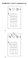
続いて、本実施形態の表示装置2における表の選択方法を説明する。まず、図1を参照して、表の作成手順を説明する。図1は、表示装置2が表の入力を受け付ける操作例を示す。
(1) ユーザーは表を入力するためのアイコン301を押下する(図1(a))。
(2) ユーザーは、フリーハンドで表302を手書きする。すなわち、ユーザーは手書きデータで表を作成する。
(3) 表示装置2は手書きデータを認識し、表303に変換する(図1(b))。すなわち、表示装置2は、縦と横、複数の平行な直線で形成される表303を表示する。
<How to create a table>
Next, a method for selecting a table in the
(1) The user presses the
(2) The user handwrites the table 302 freehand, that is, the user creates a table using handwritten data.
(3) The
このような表303に対し、本実施形態の表示装置2は、ユーザーが手書きデータで表を編集することができる。以下は、編集操作の流れである。
(1) ユーザーが手書きデータで表の一部を選択する。
(2) ユーザーが表の任意の行(列)を選択すると、ユーザーは簡単な操作で該行(列)の上(左)又は下(右)に行(列)を追加できる。
(3) 同様に、表の任意の行(列)を選択すると、ユーザーは簡単な操作で該行(列)を削除できる。
(4) 同様に、表の任意のX行(列)を選択すると、ユーザーは簡単な操作で任意のY行(列)目に移動できる。
(5) 同様に、表の任意のX行(列)を選択すると、ユーザーは簡単な操作で表の外の任意の位置にX行(列)を抜き出して表示できる。
The
(1) The user selects part of a table using handwritten data.
(2) When a user selects any row (column) in a table, the user can easily add a row (column) above (to the left) or below (to the right) of that row (column).
(3) Similarly, by selecting any row (column) in a table, the user can delete that row (column) with a simple operation.
(4) Similarly, by selecting any Xth row (column) of the table, the user can easily move to any Yth row (column).
(5) Similarly, by selecting any Xth row (column) of the table, the user can easily extract and display that Xth row (column) anywhere outside the table.
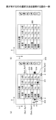
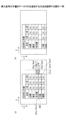
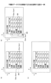
図2は、行の選択方法を説明する図である。一例として、図2(a)に示すように、ユーザーは任意の行を手書きデータの枠304で囲むことで選択できる。表示装置2は、囲まれた枠304内の領域に行オブジェクトがあるか否かを判断する。領域内のオブジェクトが行であった場合、図2(b)に示すように、表示装置2は大阪の行を選択状態にする。
Figure 2 is a diagram explaining a method for selecting a line. As an example, as shown in Figure 2(a), the user can select any line by enclosing it in a
選択状態は、表示装置2が選択された行を強調して、ユーザーに認識させる状態である。また、表示装置2は選択された行に対する操作を待ち受ける状態となる。後述するように、ユーザーはメニューを経由しないか最小限のメニュー操作で、電子ペンなどの入力手段を用いた手書きデータの入力で、表を編集できる。例えば、ユーザーは選択状態の行の前後に行を追加したり、選択状態の行を削除したり、移動したりすることができる。列についても同様である。なお、ユーザーが行又は列を選択状態にすることは必須でない。
The selected state is a state in which the
このように、本実施形態の表示装置2は、選択された行又は列について、ユーザー操作に応じて、行や列の追加、移動、又は、削除などの編集を手書きデータで実行することができるので、操作性を向上させることができる。
In this way, the
<用語について>
入力手段とはタッチパネルに座標を指定して手書きが可能な手段であればよい。例えば、ペン、人の指や手、棒状部材などがある。
<Terminology>
The input means may be any means capable of specifying coordinates on a touch panel and writing by hand, such as a pen, a human finger or hand, or a rod-shaped member.
ユーザーがディスプレーに入力手段を押しつけてから連続的に移動させた後、ディスプレーから離すという一連の操作をストロークという。ストロークデータとは、入力手段により入力される座標の軌跡に基づいてディスプレーに表示される情報である。ストロークデータは適宜、補間されてよい。手書きデータとは、1つ以上のストロークデータを有するデータである。手書き入力とは、ユーザーによって、手書きデータが入力されることを示している。 A stroke is a series of operations in which a user presses an input means against a display, moves it continuously, and then removes it from the display. Stroke data is information that is displayed on the display based on the trajectory of coordinates input by the input means. Stroke data may be appropriately interpolated. Handwritten data is data that has one or more stroke data. Handwritten input refers to handwritten data being input by a user.
ストロークデータに基づいてディスプレーに表示される表示物をオブジェクトという。オブジェクトとは対象という意味であるが、本実施形態では表示対象などの意味である。
手書きデータが文字認識して変換された文字列には、テキストデータの他、「済」などの決まった文字やマークとして表示されるスタンプ、円や星などの図形、直線等、ユーザーの操作に基づいて表示されたデータも含まれてよい。
An object is an object that is displayed on a display based on stroke data. Object means a target, but in this embodiment it means a display target.
The character string converted from handwritten data through character recognition may include not only text data, but also data displayed based on user operations, such as fixed characters such as "Done," stamps displayed as marks, shapes such as circles and stars, and straight lines.
文字列とは手書きデータから文字認識により変換された1つ以上の文字コード(フォント)である。文字列は、コンピュータで扱われる1つ以上の文字でよい。文字には、数字、アルファベット、及び、記号等が含まれる。文字列はテキストデータとも言われる。 A character string is one or more character codes (fonts) that have been converted from handwritten data using character recognition. A character string can be one or more characters that are handled by a computer. Characters include numbers, letters, and symbols. A character string is also called text data.
表示部品とは、画面を形成する色や形などの表示である。部品として表示装置2から分解できるものではなく、人間が視覚的に他と区別して認識できればよい。例えば、操作のためのメニューは表示部品である。
A display component is a display such as a color or shape that forms the screen. It is not something that can be disassembled from the
表とは情報を配列により書き表したものをいう。表は、テーブルとも呼ばれる。表は、横方向と縦方向のセルを有する。横方向に並んでいるセルを「行」と呼び、縦方向に並んでいるセルを「列」と呼ぶ。 A table is a representation of information in an array. A table is also called a table. A table has cells arranged horizontally and vertically. Cells arranged horizontally are called "rows," and cells arranged vertically are called "columns."
編集とは、著作物の修正、追加、又は、削除などをいう。本実施形態では、主に表に関する操作をいう。例えば、行(列)の追加、削除、移動、コピー、表の分割などがある。 Editing refers to modifying, adding, or deleting a work. In this embodiment, it mainly refers to operations related to tables. For example, it includes adding, deleting, moving, copying rows (columns), and splitting tables.
<構成例>
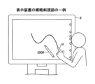
図3は、表示装置2の概略斜視図の一例を示す。表示装置2をユーザー(利用者)が利用している。本実施形態の表示装置2は、ユーザーが手又は電子ペン2500などの入力手段でディスプレー上に手書きを行うことができる。
図3の表示装置2は横置きされているが、縦置きすることも可能である。ユーザーは表示装置2をディスプレーの中心を軸に回転させて、横置きと縦置きを切り替えることができる。
<Configuration example>
3 shows an example of a schematic perspective view of the
3 is oriented horizontally, but can also be oriented vertically. The user can switch between horizontal and vertical orientations by rotating the
<ハードウェア構成例>
図4は、表示装置2のハードウェア構成の一例を示す図である。本実施形態の表示装置2は、CPU(Central Processing Unit)201、ROM(Read Only Memory)202、RAM(Random Access Memory)203、SSD(Solid State Drive)204、ネットワークコントローラ205、及び、外部機器接続I/F206(Interface)を備えており、複数の利用者により情報を共有するための共有端末である。
<Hardware configuration example>
4 is a diagram showing an example of a hardware configuration of the
これらのうち、CPU201は、表示装置2全体の動作を制御する。ROM202は、CPU201やIPL(Initial Program Loader)等のCPU201の駆動に用いられるプログラムを記憶する。RAM203は、CPU201のワークエリアとして使用される。
Of these, the
SSD204は、表示装置2用のプログラム等の各種データを記憶する。このプログラムは汎用的なOS(Windows(登録商標)、Mac OS(登録商標)、Android(登録商標)、iOS(登録商標)等)を搭載した情報処理装置で動作するアプリケーションプログラムでもよい。この場合、表示装置2は、普段は汎用的な情報処理端末として利用されるが、ユーザーがインストールされアプリケーションプログラムを実行すると、表示装置としての専用機と同様、ユーザーが手書き等することができる。
The
ネットワークコントローラ205は、ネットワークとの通信を制御する。外部機器接続I/F206は、USB(Universal Serial Bus)メモリ2600、外付け機器(カメラ2900、スピーカ2800、マイク2700)との通信を制御する。
The
また、表示装置2は、キャプチャデバイス211、GPU212、ディスプレイコントローラ213、接触センサ214、センサコントローラ215、電子ペンコントローラ216、近距離通信部219、及び近距離通信部219のアンテナ219aを備えている。
The
これらのうち、キャプチャデバイス211は、PC10のディスプレーに対して映像情報を静止画又は動画として表示させる。GPU(Graphics Processing Unit)212は、グラフィクスを専門に扱う半導体チップである。ディスプレイコントローラ213は、GPU212からの出力画像をディスプレー220等へ出力するために画面表示の制御及び管理を行う。
Of these, the
接触センサ214は、ディスプレー220上に電子ペン2500やユーザーの手H等が接触したことを検知する。電子ペン2500と手Hを区別しない場合、入力手段291という。
The
センサコントローラ215は、接触センサ214の処理を制御する。接触センサ214は、赤外線遮断方式による座標の入力及び座標の検出を行う。この座標の入力及び座標の検出する方法は、ディスプレー220の上側両端部に設置された2つ受発光装置が、ディスプレー220に平行して複数の赤外線を放射し、ディスプレー220の周囲に設けられた反射部材によって反射されて、受光素子が放射した光の光路と同一の光路上を戻って来る光を受光する方法であっても良い。
The
接触センサ214は、物体によって遮断された2つの受発光装置が放射した赤外線のIDをセンサコントローラ215に出力し、センサコントローラ215が、物体の接触位置である座標位置を特定する。電子ペンコントローラ216は、電子ペン2500と通信することで、ディスプレー220へのペン先のタッチやペン尻のタッチの有無を判断する。近距離通信部219は、NFC、Bluetooth(登録商標)等の通信回路である。
The
更に、表示装置2は、バスライン210を備えている。バスライン210は、CPU201等の各構成要素を電気的に接続するためのアドレスバスやデータバス等である。
The
なお、接触センサ214は、赤外線遮断方式に限らず、静電容量の変化を検知することにより接触位置を特定する静電容量方式のタッチパネル、対向する2つの抵抗膜の電圧変化によって接触位置を特定する抵抗膜方式のタッチパネル、接触物体が表示部に接触することによって生じる電磁誘導を検知して接触位置を特定する電磁誘導方式のタッチパネルなどの種々の検出手段を用いても良い。また、電子ペンコントローラ216が、電子ペン2500のペン先及びペン尻だけでなく、電子ペン2500のユーザーが握る部分や、その他の電子ペンの部分のタッチの有無を判断するようにしても良い。
The
<機能について>
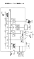
次に、図5を用いて表示装置2の機能について説明する。図5は、表示装置2が有する機能をブロック状に分けて説明する機能ブロック図の一例である。表示装置2は、接触位置検出部40、描画データ生成部41、描画オブジェクト管理部42、表オブジェクト管理部43、オブジェクト選択部44、表示制御部45、会議データ記憶部46、ネットワーク通信部47、記号認識部48、及び プレビュー画像生成部49を有している。表示装置2が有する各機能は、図4に示されている各構成要素のいずれかが、SSD204からRAM203上に展開されたプログラムに従ったCPU201からの命令によって動作することで実現される機能又は手段である。
<About the function>
Next, the functions of the
接触位置検出部40は、入力手段291の先端がディスプレーに接触したため接触センサ214が検出した座標を検出する。描画データ生成部41は入力手段291の先端が接触した座標を接触位置検出部40から取得する。描画データ生成部41はこの座標点列を補間することで接続して、ストロークデータを生成する。また、描画データ生成部41は、手書きデータに基づいて記号認識部48が認識した円や矩形等の図形を生成する。
The contact
描画オブジェクト管理部42は、描画データ生成部41が生成した手書きデータの領域、円や矩形等の図形の領域、及び、表など領域を描画オブジェクトとして、描画オブジェクトIDを付与するなどにより、これらの領域を管理する。また、描画オブジェクト管理部42は、各描画オブジェクトの表示位置(座標)も管理する。表オブジェクトは、描画オブジェクト管理部42により描画オブジェクトIDや表示位置を管理されるが、表オブジェクト管理部43は表内に記載される行や列のオブジェクトを管理する。表オブジェクト管理部43は表内の手書きデータや文字列を管理したり、行や列の順番を入れ替えたり等、表に特有の処理を行う。
The drawing
オブジェクト選択部44は手書きデータで形成された領域、又は、矢印など所定の形状の手書きデータで選択される行又は列の選択を受け付ける。オブジェクト選択部44はセルの選択を受け付けてもよい。オブジェクト選択部44は、オブジェクトを選択状態にする。
The
表示制御部45は、手書きデータ、文字列、表、及び、操作メニュー等をディスプレーに表示する。ネットワーク通信部47はLANやインターネット等のネットワークに接続して、他の機器とネットワークを介したデータの送受信を行う。
The
会議データ記憶部46は会議で使用された資料(ファイル)、手書きデータ、画像データ、及び、文字列等をハードディスク等の記憶装置に記憶させる。
The conference
プレビュー画像生成部49は、行の移動結果や表の分割結果などを、表オブジェクト管理部43が実際に移動又は分割する前に、プレビューデータ画像として表示する。
The preview
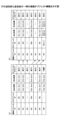
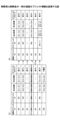
<描画オブジェクト情報、行オブジェクト情報>
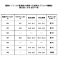
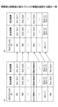
図6は描画オブジェクト管理部42が保持する描画オブジェクト情報を模式的に示す。描画オブジェクト情報は、表示装置2が表示する描画オブジェクトを管理する情報である。
<Drawing object information, line object information>
6 is a diagram showing a schematic diagram of the drawing object information held by the drawing
・描画オブジェクトIDは描画オブジェクトを識別する識別情報である。描画オブジェクトは画面に表示されている各種の表示物の全てをいう。図6の描画オブジェクトID=001の描画オブジェクトは、1つの表の各行である。図6の最下行の描画オブジェクトIDが002になっているのは、表に手描きされた囲み線や矢印の手書きデータを表している。 The drawing object ID is identification information that identifies a drawing object. A drawing object refers to all of the various display objects that are displayed on the screen. In Figure 6, the drawing object with drawing object ID = 001 is each row of a table. The bottom row in Figure 6 has a drawing object ID of 002, which represents handwritten data of an encirclement line and arrow that have been handwritten in the table.
・行オブジェクトIDは描画オブジェクトが表であり、その中の行オブジェクトに設定されるものであり、行オブジェクトを識別する識別情報である。行オブジェクトは1つの表の中の1行である。列オブジェクトについても同様に列オブジェクトIDが付与される。 - The drawing object is a table, and the row object ID is set for the row object within the table; it is identification information that identifies the row object. A row object is one row in a table. Column objects are also assigned column object IDs in the same way.
・起点座標は、表示装置2の画面の所定の原点を基準として描画オブジェクトの起点の位置を示す。描画オブジェクトの起点は例えば描画オブジェクトの外接矩形の左上の角である。座標は例えば、ディスプレーの画素単位で表される。
The origin coordinates indicate the position of the origin of a drawing object relative to a predetermined origin on the screen of the
・終点座標は、表示装置2の画面の所定の原点を基準として描画オブジェクトの終点の位置を示す。描画オブジェクトの終点は例えば描画オブジェクトの外接矩形の右下の角である。
The end point coordinates indicate the position of the end point of the drawing object relative to a predetermined origin on the screen of the
・オブジェクトのタイプは描画オブジェクトの種類である。例えば、表(行又は列)、手書き、文字列、図形、画像、等がある。表(行)は行オブジェクトを示す。手書きはストロークデータ(座標点列)である。文字は手書きデータから変換された文字列(文字コード)である。文字列をテキストデータという場合もある。図形は、三角や四角など手書きデータから変換された幾何学的な形状である。画像は、PCやインターネットなどから取り込まれたJpeg、Png、Tiffなどの画像データである。 - The object type is the type of drawing object. Examples include table (row or column), handwriting, string, shape, image, etc. Table (row) indicates a row object. Handwriting is stroke data (sequence of coordinate points). Characters are strings of characters (character codes) converted from handwritten data. Strings are sometimes called text data. Shapes are geometric shapes such as triangles and squares converted from handwritten data. Images are image data such as Jpeg, PNG, Tiff, etc. imported from a PC or the Internet.
図7は、行オブジェクト情報を模式的に示す。行オブジェクト情報は描画オブジェクトから行オブジェクトのみを取り出した情報である。 Figure 7 shows a schematic of line object information. Line object information is information that extracts only line objects from drawing objects.
・行オブジェクトIDは表の中の行(又は列)を識別する識別情報である。 - The row object ID is identification information that identifies a row (or column) in a table.
・起点座標は1行の起点の座標である。 The starting coordinates are the coordinates of the starting point of a line.
・終点座標は1行の終点の座標である。 - The end coordinates are the coordinates of the end point of a line.
<表の行又は列の選択>
図8は、表が有する行の選択方法を説明する図である。まず、図8を参照して、描画オブジェクト管理部42が管理する行オブジェクトの表示位置について説明する。ディスプレーの表示画素の位置は、表示領域の左上の角にある画素位置を原点として、右方向をX軸の正の方向、下方向をY軸の正の方向とした表示座標で表現する。
<Selecting a row or column in a table>
Fig. 8 is a diagram for explaining a method for selecting rows in a table. First, the display position of a row object managed by the drawing
すなわち、
座標=(原点位置の画素からのX軸方向の画素数,原点位置の画素からのY軸方向の画素数)
である。
That is,
Coordinates = (number of pixels in the X-axis direction from the pixel at the origin, number of pixels in the Y-axis direction from the pixel at the origin)
It is.
また、描画オブジェクト管理部42は描画オブジェクトの領域を描画オブジェクトに外接する矩形で管理し、この矩形領域の左上の角にある画素位置を起点座標、矩形領域の右下の角にある画素位置を終点座標とする。行オブジェクトの場合、行の外接矩形の左上の角を起点座標(Sxk,Syk)、外接矩形の右下の角を終点座標(Exk,Eyk)とする。ここでkは1行目から順番に付与される行番号である。例えば、選択された行をm行とすれば、起点座標が(Sxm,Sym)、終点座標が(Exm,Eym)である。
The drawing
タッチパネルの接触座標の間隔はディスプレーの表示座標の間隔と同じであり、両者の座標は一致しているものとする。 The spacing between contact coordinates on the touch panel is the same as the spacing between display coordinates on the display, and the two coordinates are assumed to match.
図8(a)に示すように、表示装置2が表を表示している。ユーザーがオブジェクト選択アイコンを選択すると、接触位置検出部40が検出する座標により、描画オブジェクト管理部42がオブジェクト選択モードであると判断する。オブジェクト選択アイコンの押下は必ずしも必要ない。
As shown in FIG. 8(a), the
ユーザーは手書きで支店の項目が大阪の行を枠304で囲む。オブジェクト選択部44は接触位置検出部40が検出した枠304の座標から最下端311、最左端312、最上端313、最右端314の座標を算出し、手書きで描いた枠304が大阪の行を囲んだと判断する(詳細はフローチャート図で説明する)。そして、オブジェクト選択部44は大阪の行を選択状態にする。なお、図8(a)では1行のみが選択されているが、ユーザーは複数行を選択することができる。
The user hand-draws a
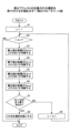
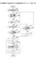
選択の詳細を図9のフローチャートで説明する。図9は、表オブジェクトの任意の行の選択を受け付ける手順を示すフローチャート図である。図8(a)の札幌から順に行オブジェクトIDを1、2、…nとする。ユーザーが手書きデータで囲んだm行目の行の外接矩形における左上の角の座標を起点座標(Sxm, Sym)とし、右下の座標を終点座標(Exm, Eym)とする。 The details of the selection are explained in the flowchart in Figure 9. Figure 9 is a flowchart showing the procedure for accepting the selection of any row in a table object. Let the row object IDs be 1, 2, ... n, starting from Sapporo in Figure 8(a). The coordinates of the upper left corner of the circumscribing rectangle of the mth row enclosed by the user's handwritten data be the starting coordinates (Sxm, Sym), and the coordinates of the lower right be the ending coordinates (Exm, Eym).
まず、図9の処理の概略は以下のとおりである。ユーザーがオブジェクト選択モードで行を囲むと、オブジェクト選択部44は接触位置検出部40が検出した座標から、ストロークデータで囲んだ領域がk行目よりd小さい領域を包括するか判断する。dはストロークデータが1つの行を完全に囲んでいない場合でも行の選択を可能にするためのマージンである。ストロークデータで囲まれた領域がk行目よりd小さい領域を包括するとオブジェクト選択部44が判断した場合、その行を選択状態にする。オブジェクト選択部44は、この処理をk=1からn行目まで繰り返す。
First, the process in FIG. 9 is outlined below. When the user surrounds a line in object selection mode, the
図8(a)では大阪の行が選択されているので、図8(b)では大阪の行が選択状態である。オブジェクト選択部44は大阪の行の色を変えたり、線305で囲んだりすることで強調する。
In FIG. 8(a), the row for Osaka is selected, and so in FIG. 8(b), the row for Osaka is in a selected state. The
図9について説明する。オブジェクト選択部44は変数kに1を設定する(S1)。kは行番号を表す。オブジェクト選択部44は終了条件(k≦nがNo)を満たすか否かを判断する(S2)。nは表が有する行数である。終了条件により、最後の行まで手書きデータで囲まれたか否かの判断が終了したことが判断される。
Referring to FIG. 9, the
終了条件を満たさない場合、オブジェクト選択部44は最上端313の座標がSyk+dより大きいか否かを判断する(S3)。
If the termination condition is not met, the
同様に、オブジェクト選択部44は最下端311の座標がEyk-dより小さいか否かを判断する(S4)。
Similarly, the
オブジェクト選択部44は最右端314の座標がExk-dより大きいか否かを判断する(S5)。
The
オブジェクト選択部44は最左端312の座標がSxk+dより小さいか否かを判断する(S6)。
The
ステップS3~S6が全てYesの場合(S7のYes)、オブジェクト選択部44はk行目を選択状態にする(S8)。
If steps S3 to S6 are all Yes (Yes in S7), the
ステップS7において、ステップS3~S6のうち1つでもNoの場合、オブジェクト選択部44はkを1つ大きくする(S9)。すなわち、オブジェクト選択部44は、次の行が選択されたかどうかを判断する。
In step S7, if any one of steps S3 to S6 is No, the
なお、図9のように全ての行について選択されたかどうかをオブジェクト選択部44が判断するのでなく、ストロークデータの外接矩形が重なっている行のみを判断してもよい。
In addition, instead of the
このように、ユーザーは行をストロークデータで囲むという簡単な方法で行を選択できる。 This way, the user can select a line simply by surrounding it with stroke data.
<行の選択方法の別の例>
行を選択する方法としては、ユーザーが行をストロークデータで囲む方法以外にも、行の隣に矢印を書く方法でもよい。
<Another example of how to select rows>
As a method for selecting a line, the user may select the line by drawing an arrow next to the line, in addition to the method of surrounding the line with stroke data.
図10は、ユーザーが矢印で行を選択する方法を説明する図である。図10(a)に示すようにユーザーは支店の項目が大阪の行の隣に、大阪に向かって矢印320を手書きする。矢印320の外接矩形における左上の角の座標を起点座標(Sxp, Syp)とし、右下の角の座標を終点座標(Exp, Eyp)とする。
Figure 10 is a diagram explaining how a user can select a row with an arrow. As shown in Figure 10 (a), the user hand-draws an
また、枠から距離Lの範囲が、ユーザーが行を選択する記号を手書きする範囲(記号の検出範囲)として予め定められている。ユーザーが選択された行とは関係なく手書きしたい場合があるためである。また、図10(a)では表の左隣に矢印が手書きされているが、表の右隣から距離Lの範囲も記号の検出範囲でよい。 The range of distance L from the frame is predefined as the range in which the user can handwrite a symbol to select a row (symbol detection range). This is because there are cases in which the user wants to handwrite something regardless of the selected row. Also, in FIG. 10(a), an arrow is handwritten to the left of the table, but the range of distance L from the right of the table can also be the symbol detection range.
オブジェクト選択部44は描画オブジェクト情報に基づいて、手書きデータが矢印であり、かつ、大阪の行の隣であると判断すると、大阪の行を選択状態にする(図10(b))。
When the
図11は、表オブジェクトの任意の行の選択を受け付ける手順を示すフローチャート図である。 Figure 11 is a flow chart showing the procedure for accepting the selection of any row in a table object.
ユーザーが大阪の行隣に矢印320を手書きすると、オブジェクト選択部44はオブジェクト情報記憶部から描画オブジェクトの座標と大きさを取得し、表から距離L以内に手書きデータがあるか否かを判断する(S11)。図6を例にすると、描画オブジェクトとして描画オブジェクトID=002の矢印が、表だけの描画オブジェクトに追加された状態となる。
When the user handwrites an
次に、表オブジェクト管理部43は手書き線が矢印320かどうかの判断を行う(S12)。すなわち、表オブジェクト管理部43は、選択された行の付近の手書きデータが予め定められている記号に認識されたかどうかを判断する。
Next, the table
矢印320の場合、オブジェクト選択部44は変数kに1を設定する(S13)。kは行番号を表す。なお、手書きデータの認識は記号認識部48が行う。矢印は一例であって、チェックマークなど各種の記号が選択用の記号として設定されていてよい。
In the case of the
オブジェクト選択部44は終了条件(k≦nでNo)を満たすか否かを判断する(S14)。nは表が有する行数である。
The
終了条件を満たさない場合、オブジェクト選択部44は、矢印の中心y座標(Syp+Eyp)/2が、選択されている行の高さに相当するSymとEymの間にあるか否かを判断する(S15)。
If the termination condition is not met, the
ステップS15の判断がYesである場合、オブジェクト選択部44はk行目を選択状態にする(S17)。
If the determination in step S15 is Yes, the
ステップS15の判断がNoである場合、オブジェクト選択部44はkを1つ大きくし、ステップS14に戻る(S16)。
If the determination in step S15 is No, the
このように、ユーザーは行の横に記号を手書きすることで、任意の行を選択状態にできる。 In this way, the user can select any row by handwriting a symbol next to it.
なお、図11のように全ての行について選択されたかどうかをオブジェクト選択部44が判断するのでなく、ストロークデータのY座標が重なっている行のみを判断してもよい。
In addition, instead of the
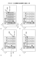
<行の追加方法 その1>
ユーザーが行を選択状態にすると、大阪の行の前後に、表示制御部45が行を追加するためのボタンや削除するためのボタンを表示する。
<How to add a
When the user places a row in a selected state, the
図12(a)は、ボタン321~323が表示された表の一例を示す。選択された大阪の行の右側に3つのボタン321~323が表示される。ボタン321~323の位置は図示する位置に限られない。ボタン321~323は選択されている行の付近にあればよい。
Figure 12 (a) shows an example of a table in which
ボタン321は選択されている行の上にユーザーが行を追加するためのボタンである。ボタン323は選択されている行の下にユーザーが行を追加するためのボタンである。ボタン322は選択されている行をユーザーが削除するためのボタンである。
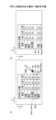
ユーザーがボタン321を押下すると、表オブジェクト管理部43は大阪の行の上に行を追加して表示する(図12(b)))。表オブジェクト管理部43は追加された行に新しい行オブジェクトIDを、1行目から連番で設定する。したがって、追加された行がm行目となり、選択された行以下の行オブジェクトIDは1つずつ増える。
When the user presses
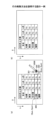
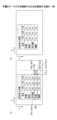
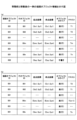
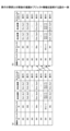
図13は、行の追加前と追加後の表オブジェクト情報を示す。図13(a)は行の追加前の表オブジェクト情報であり、図13(b)は行の追加後の表オブジェクト情報である。m行目が追加された行に相当する。行が追加されたため、行数がnからn+1に1つ増えている。 Figure 13 shows the table object information before and after a row is added. Figure 13 (a) shows the table object information before a row is added, and Figure 13 (b) shows the table object information after a row is added. The mth row corresponds to the added row. Because a row was added, the number of rows has increased by one, from n to n+1.
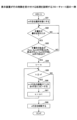
図14は、表示装置2が行の追加を受け付ける処理を説明するフローチャート図の一例である。
Figure 14 is an example of a flowchart illustrating the process by which the
まず、図9,図11で説明したように、オブジェクト選択部44がm行目を選択状態にする(S21)。
First, as described in Figures 9 and 11, the
これにより、表示制御部45がm行目に行を追加するボタン321とm行目の後(m+1行目)に行を追加するボタン323を表示する(S22)。ボタン322も表示されるが、詳細は後述する。
As a result, the
表オブジェクト管理部43は、接触位置検出部40が検出する入力手段291の接触位置に応じて、行を追加するボタン321が押下されたと判断する(S23)。
The table
表オブジェクト管理部43は表の最後に空白の1行を追加する(S24)。
The table
また、押下されたボタン321がm行目に行を追加するためのボタン321であった場合(S25のYes)、表オブジェクト管理部43は最終行を設定するため、変数kにnを設定する(S26)。kは行番号を表す。
If the pressed
押下されたボタン323がm+1行目に行を追加するためのボタン323であった場合(S25のNo)、表オブジェクト管理部43はmを1つ大きくする(S27)。これは、1行早くコピー処理を終了するためである。
If the pressed
表オブジェクト管理部43は終了条件(m≦kでNo)を満たすか否かを判断する(S28)。この終了条件は、コピー処理の対象行(変数k)が選択行mより大きいかどうかを判断している。
The table
終了条件を満たさない場合、表オブジェクト管理部43は、k行目の描画オブジェクトをk+1行目にコピーする(S29)。k行目の描画オブジェクトは消去される。
If the termination condition is not met, the table
そして、表オブジェクト管理部43はkを1つ小さくして(S30)、ステップS28から処理を繰り返す。
Then, the table
したがって、k=n, n-1, n-2, …, m(又はm+1)になるまで、1つ上の行の描画オブジェクトが1つ下の行にコピーされる。 Therefore, the drawing objects in the row above are copied to the row below until k = n, n-1, n-2, ..., m (or m+1).
このように、ユーザーは行を手書きデータで囲んでボタン321,323を押下することで行を追加できる。
In this way, the user can add a line by surrounding it with handwritten data and
<行の追加方法 その2>
次に、図15を参照して、行の追加方法(その2)を説明する。図15は手書きデータで表に行を追加する方法を説明する図である。
<How to add a
Next, a second method for adding a row will be described with reference to Fig. 15. Fig. 15 is a diagram for explaining a method for adding a row to a table using handwritten data.
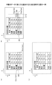
図15(a)に示すように、大阪の行が選択状態であるとする。次に、ユーザーが所定のマーク(ここでは+マーク325)を大阪の行の高さの半分より上に手書きする(図15(b))。+マーク325の外接矩形における左上の角の座標を(Sxp,Syp)とし、右下の角の座標を(Exp,Eyp)とする。
As shown in Figure 15(a), assume that the row for Osaka is selected. Next, the user handwrites a given mark (here, a + mark 325) above half the height of the row for Osaka (Figure 15(b)). The coordinates of the upper left corner of the circumscribing rectangle for the +
表オブジェクト管理部43は手書きデータが+マーク325であるか否かを判断する。+マーク325の場合、表オブジェクト管理部43は、書き込まれた位置が選択されている大阪の行の半分より上か又は下か判断する。大阪の行の半分より上に書き込まれたと判断された場合、表オブジェクト管理部43は大阪の行の上に行を追加して表示する(図15(c))。大阪の行の半分より下に書き込まれたと判断された場合、表オブジェクト管理部43は大阪の行の下に行を追加して表示する。
The table
図16は、表示装置2が行の追加を受け付ける処理を説明するフローチャート図の一例である。図16の説明では主に図14との相違を説明する。図16ではボタン321、323でなく+マーク325の手書きデータで行が追加される。
Figure 16 is an example of a flow chart illustrating the process in which the
オブジェクト選択部44がm行目を選択状態にする(S31)。
The
ユーザーが大阪の行と名古屋の行の境界に+マーク325を手書きすると、オブジェクト選択部44はオブジェクト情報記憶部から描画オブジェクトの座標と大きさを取得し、表から距離L以内に手書きデータがあるかを判断する(S32)。
When the user handwrites a
次に、表オブジェクト管理部43は、記号認識部48が+マーク325を認識したかどうかの判断を行う(S33)。+マーク325は一例であって、他の記号が行の追加用に設定されていてよい。
Next, the table
+マーク325が手書きされると、表オブジェクト管理部43は表の最後に空白の1行を追加する(S34)。
When the +
次に、表オブジェクト管理部43は、+マークの中心y座標(Syp+Eyp)/2がm行目の高さの中心(Sym+Eym)/2より大きいか判断する(S35)。表オブジェクト管理部43は、単に大きいか小さいかだけでなく、選択行の高さ方向に対し上限と下限を設けて+マーク325がある場所を判断してよい。
Next, the table
ステップS35の判断がNoの場合、表オブジェクト管理部43はmを1つ大きくする(S36)。
If the determination in step S35 is No, the table
ステップS37~S40の処理は図14のステップS27~S30と同様でよい。すなわち、ステップS35の判断がYesの場合、選択された行の上に新しい行が追加されるように、表オブジェクト管理部43は、k行目のテキストをk+1行目へコピーすることをk=nからk=mになるまで繰り返す。
The processing in steps S37 to S40 may be the same as steps S27 to S30 in FIG. 14. That is, if the determination in step S35 is Yes, the table
ステップS35の判断がNoの場合、選択された行の下に新しい行が追加されるように、k行目のテキストをk+1行目へコピーすることをk=nからk=m+1になるまで繰り返す。 If the determination in step S35 is No, the text in the kth line is copied to the k+1th line so that a new line is added below the selected line, and this process is repeated from k=n to k=m+1.
このように、ユーザーは行を手書きデータで囲んで、更に、+マークの手書きデータで行を追加できる。 This way, the user can surround a line with handwritten data and then add additional lines with handwritten data containing a + symbol.
図17は、行の追加前と追加後の描画オブジェクト情報を示す。図17(a)は行の追加前の描画オブジェクト情報であり、図17(b)は行の追加後の描画オブジェクト情報である。図17(a)のm行目が選択された行である。+マーク325の中心y座標がm行目の高さの中心より大きい場合、m行目が追加される。また、図17(a)では描画オブジェクトID=002に+マーク325の手書きデータが登録されている。
Figure 17 shows the drawing object information before and after a line is added. Figure 17(a) shows the drawing object information before a line is added, and Figure 17(b) shows the drawing object information after a line is added. The mth line in Figure 17(a) is the selected line. If the central y coordinate of the +
図17(b)では、行が追加されたため、行数がnからn+1に1つ増えている。また、描画オブジェクトID=002の+マーク325は消去されるので、描画オブジェクト情報からも消去される。
In FIG. 17(b), a row has been added, so the number of rows has increased by one from n to n+1. Also, the +
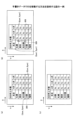
<行の追加方法 その3>
次に、図18を参照して、行の追加方法(その3)を説明する。図18は、挿入記号の手書きデータで行を追加する方法を説明する図である。
<How to add a row 3>
Next, a third method for adding a line will be described with reference to Fig. 18. Fig. 18 is a diagram for explaining a method for adding a line using handwritten data of an insertion symbol.
図18(a)に示すように、大阪の行が選択状態であるとする。次に、ユーザーが所定のマーク(ここでは<マーク326)を名古屋と大阪の間に手書きする。表オブジェクト管理部43は手書きデータが<マーク326であると判断する。<マーク326の場合、表オブジェクト管理部43は、<マーク326の先端の位置がどの行間であるか判断する。名古屋と大阪の間であると判断された場合、表オブジェクト管理部43は大阪の上に行を追加して表示する(図18(b))。
As shown in FIG. 18(a), assume that the row for Osaka is selected. Next, the user handwrites a specified mark (here, the < mark 326) between Nagoya and Osaka. The table
図19は、表示装置2が行の追加を受け付ける処理を説明するフローチャート図の一例である。図19の説明では主に図16との相違を説明する。図19では+マーク325でなく<マーク326の手書きデータで行が追加される。まず、ステップS41,S42は図16のステップS31,32と同様でよい。
Figure 19 is an example of a flow chart illustrating the process in which the
ステップS43で、表オブジェクト管理部43は、記号認識部48が<マーク326を検出したか否かを判断する(S43)。
In step S43, the table
ステップS44は図16のステップS34と同様でよい。 Step S44 may be similar to step S34 in FIG. 16.
そして、表オブジェクト管理部43は、<マーク326の先端が選択された行の上端から±h(Sym±hの範囲)内にあるか判断する(S45)。hはマージンである。
Then, the table
ステップS45の判断がNoの場合、表オブジェクト管理部43は、<マーク326の先端が選択された行の下端から±h(Eym±hの範囲)内にあるか判断する(S46)。hはマージンである。
If the determination in step S45 is No, the table
以降の処理のステップS47~S51は図16のステップS36~S40と同様でよい。すなわち、ステップS45の判断がYesの場合、選択された行の上に新しい行が追加されるように、表オブジェクト管理部43は、k行目のテキストをk+1行目へコピーすることをk=nからk=mになるまで繰り返す。
The subsequent processing steps S47 to S51 may be the same as steps S36 to S40 in FIG. 16. That is, if the determination in step S45 is Yes, the table
ステップS46の判断がYesの場合、選択された行の下に新しい行が追加されるように、k行目のテキストをk+1行目へコピーすることをk=nからk=m+1になるまで繰り返す。 If the answer to step S46 is Yes, the text in the kth line is copied to the k+1th line so that a new line is added below the selected line, and this process is repeated from k=n to k=m+1.
このように、ユーザーは行を手書きデータで囲んで、更に、<マークの手書きデータで行を追加できる。 This way, the user can surround a line with handwritten data and then add additional lines with handwritten data with the < mark.
図20は、行の追加前と追加後の描画オブジェクト情報を示す。図20の説明では主に図17との相違を説明する。図20は図17と形式は同じであるが、図20(a)では描画オブジェクトID=002に<マーク326の手書きデータが登録されている。図20(b)については図17(b)と同じでよい。
Figure 20 shows the drawing object information before and after a line is added. The explanation of Figure 20 will mainly focus on the differences from Figure 17. Figure 20 has the same format as Figure 17, but in Figure 20(a), handwritten data for the <
<行の削除方法 その1>
続いて、図21等を参照して行の削除方法について説明する。図21は、行の削除方法を説明する図である。行が選択状態となることでボタン321~323が表示されるまでは、図12と同じでよい。
<How to delete a
Next, a method for deleting a row will be described with reference to Fig. 21 etc. Fig. 21 is a diagram for explaining the method for deleting a row. The process may be the same as Fig. 12 until the row is selected and
図21(a)に示すように、大阪の行が選択状態になると、表示制御部45が行を削除するためのボタン322を選択された行の右隣に表示する。ユーザーが大阪の行を削除するためのボタン322を押下すると、表オブジェクト管理部43は大阪の行を削除し、名古屋の行の下に福岡の行を続けて表示する(図21(b))。
As shown in FIG. 21(a), when the row for Osaka is selected, the
図22は、表示装置2が行の削除を受け付ける処理を説明するフローチャート図の一例である。
Figure 22 is an example of a flowchart illustrating the process by which the
まず、オブジェクト選択部44がm行目を選択状態にする(S61)。
First, the
これにより、表示制御部45がm行目を削除するボタン322を表示する(S62)。
This causes the
表オブジェクト管理部43は、接触位置検出部40が検出する入力手段291の接触位置に応じて、行を削除するボタン322が押下されたか否かを判断する(S63)。
The table
削除するボタン322が押下された場合、表オブジェクト管理部43は変数kにmを設定する(S64)。これは、m+1行目以降の描画オブジェクトを1行ずつ繰り上げるためである(列の操作の場合は、m+1列目以降の描画オブジェクトが1列ずつ繰り上がる)。
When the
表オブジェクト管理部43は終了条件(k≦nでNo)を満たすか否かを判断する(S65)。
The table
終了条件を満たさない場合、表オブジェクト管理部43は、k+1行目のテキストをk行目にコピーする(S66)。
If the termination condition is not met, the table
そして、表オブジェクト管理部43はkを1つ大きくして(S67)、ステップS65から処理を繰り返す。したがって、表オブジェクト管理部43はk+1行目のテキストをk行目にコピーすることをk=mからk=nまで繰り返す。
Then, the table
終了条件を満たす場合、表オブジェクト管理部43は、n行目を削除する(S68)。すなわち、表オブジェクト管理部43は最下行を削除する。
If the termination condition is met, the table
このように、ユーザーは行を手書きデータで囲んでボタンを押下することで行を削除できる。 In this way, the user can delete a line by surrounding it with handwritten data and pressing a button.
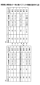
図23は、削除前と削除後の表オブジェクト情報を説明する図である。図23(a)が削除前の表オブジェクト情報を、図23(b)が削除後の表オブジェクト情報を示す。n行あった表オブジェクト情報がn-1行になっている。図23(a)のm行目が削除されたので、図23(b)のm行目の描画オブジェクトは図23(a)のm+1行目の行の内容に置き換わっている。 Figure 23 is a diagram explaining the table object information before and after deletion. Figure 23(a) shows the table object information before deletion, and Figure 23(b) shows the table object information after deletion. The table object information that had n rows has now become n-1 rows. Because row m in Figure 23(a) has been deleted, the drawing object in row m in Figure 23(b) has been replaced with the contents of row m+1 in Figure 23(a).
<行の削除方法 その2>
次に、図24を参照して、行の削除方法(その2)を説明する。図24は、手書きデータで行を削除する方法を説明する図である。
<How to delete a
Next, a line deletion method (part 2) will be described with reference to Fig. 24. Fig. 24 is a diagram for explaining a method for deleting a line in handwritten data.
図24(a)に示すように、大阪の行が選択状態であるとする。次に、ユーザーが所定のマーク(ここでは×マーク327)を大阪の行の隣に手書きする。表オブジェクト管理部43は手書きデータが×マーク327であると判断する。×マーク327の場合、表オブジェクト管理部43は、書き込まれた位置がどの行であるかを判断する。大阪の行の隣と判断された場合、表オブジェクト管理部43は大阪の行を削除して、名古屋の行に続けて福岡の行を表示する(図24(b))。
As shown in FIG. 24(a), assume that the row for Osaka is selected. Next, the user handwrites a specified mark (here, an x mark 327) next to the row for Osaka. The table
図25は、表示装置2が行の削除を受け付ける処理を説明するフローチャート図の一例である。図25の説明では主に図19又は図22との相違を説明する。図25ではボタンでなく×マークの手書きデータで行が削除される。
Figure 25 is an example of a flow chart illustrating the process in which the
まず、ステップS71,S72は図19のステップS41,S42と同様でよい。 First, steps S71 and S72 may be similar to steps S41 and S42 in FIG. 19.
次に、描画オブジェクト管理部42は、×マーク327が手書きされたか否かを判断する(S73)。×マーク327の認識は記号認識部48が行う。
Next, the drawing
ステップS74~S78は図22のステップS64~S68と同様でよい。 Steps S74 to S78 may be similar to steps S64 to S68 in FIG. 22.
すなわち、×マークが手書きされた場合、表オブジェクト管理部43は、k+1行目のテキストをk行目にコピーすることをk=mからk=nまで繰り返す。繰り返し処理が終わると表オブジェクト管理部43は、n行目を削除する。
In other words, when an X mark is handwritten, the table
このように、ユーザーは行を手書きデータで囲んで、更に、×マークの手書きデータで行を削除できる。 In this way, the user can surround a line with handwritten data and then delete the line with handwritten data of an X mark.
図26は、削除前と削除後の表オブジェクト情報を説明する図である。図26(a)が削除前の描画オブジェクト情報を、図26(b)が削除後の描画オブジェクト情報を示す。図26の説明では、主に図23との相違を説明する。 Figure 26 is a diagram explaining table object information before and after deletion. Figure 26 (a) shows the drawing object information before deletion, and Figure 26 (b) shows the drawing object information after deletion. The explanation of Figure 26 will mainly focus on the differences from Figure 23.
図26(a)の描画オブジェクト情報は、×マークに相当する描画オブジェクトID=002の手書きデータを有している。図26(b)に示すように、n行あった行オブジェクトがn-1行になっている。図26(a)のm行目が削除されたので、図26(b)のm行目の描画オブジェクトは図26(a)のm+1行目の行の内容に置き換わっている。また、描画オブジェクトID=002の×マーク327が消去されるので、描画オブジェクト情報からも消去される。
The drawing object information in FIG. 26(a) has handwritten data with drawing object ID=002, which corresponds to an x mark. As shown in FIG. 26(b), the n-row line object has become n-1 rows. Because row m in FIG. 26(a) has been deleted, the drawing object in row m in FIG. 26(b) has been replaced with the contents of row m+1 in FIG. 26(a). In addition, because the
<行の削除方法 その3>
次に、図27を参照して、行の削除方法(その3)を説明する。図27は、手書きデータで行を削除する方法を説明する図である。
<How to delete a row 3>
Next, a line deletion method (part 3) will be described with reference to Fig. 27. Fig. 27 is a diagram for explaining a method for deleting a line in handwritten data.
図27(a)に示すように、大阪の行が選択状態であるとする。次に、ユーザーが大阪の行に斜線328を手書きする。表オブジェクト管理部43は選択された行に重畳して斜線328が手書きされたかを判断する。選択された行に重畳して斜線328が手書きされた場合、表オブジェクト管理部43は、書き込まれた位置がどの行であるかを判断する。書き込まれた行が選択されている大阪の行と判断された場合、表オブジェクト管理部43は大阪の行を削除して、名古屋の行に続けて福岡の行を表示する(図27(b))。
As shown in FIG. 27(a), assume that the row for Osaka is selected. Next, the user handwrites a
図28は、表示装置2が行の削除を受け付ける処理を説明するフローチャート図の一例である。図28の説明では主に図25との相違を説明する。図28では×マーク325でなく斜線328の手書きデータで行が削除される。
Figure 28 is an example of a flow chart illustrating the process in which the
まず、ステップS81は図25のステップS71と同様でよい。 First, step S81 may be the same as step S71 in FIG. 25.
表オブジェクト管理部43は手書きデータが手書きされたか否かを判断する(S82)。すなわち、表オブジェクト管理部43は単に手書きされたかどうかを判断すればよい。
The table
次に、表オブジェクト管理部43は斜線328がm行目に手書きされたか否かを判断する(S83)。すなわち、表オブジェクト管理部43は、手書きデータの始点(Sxp,Syp)が、m行目の左上座標(Sxm,Sym)の半径d以内、かつ、終点(Exp,Eyp)がm行目の右下座標(Exm,Eym)の半径d以内かどうかを判断する。dはマージンである。
Next, the table
ステップS84~S88は図25のステップS74~S78と同様でよい。すなわち、m行目に斜線が手書きされた場合、表オブジェクト管理部43は、k+1行目のテキストをk行目にコピーすることをk=mからk=nまで繰り返す。繰り返し処理が終わるとn行目を削除する。
Steps S84 to S88 may be the same as steps S74 to S78 in FIG. 25. That is, if a diagonal line is handwritten on line m, the table
このように、ユーザーは行を手書きデータで囲んで、更に、斜線328を手書きすることで行を削除できる。
In this way, the user can delete a line by enclosing it in handwritten data and then manually drawing the
図29は、削除前と削除後の描画オブジェクト情報を説明する図である。図29(a)が削除前の描画オブジェクト情報を、図29(b)が削除後の描画オブジェクト情報を示す。図29の説明では、主に図26との相違を説明する。 Figure 29 is a diagram explaining the drawing object information before and after deletion. Figure 29 (a) shows the drawing object information before deletion, and Figure 29 (b) shows the drawing object information after deletion. The explanation of Figure 29 will mainly focus on the differences from Figure 26.
図29の描画オブジェクト情報は形式的には図26と同様である。ただし、図29(a)において、描画オブジェクトID=002の手書きデータは斜線328である。図29(b)は図26(b)と同様でよい。
The drawing object information in FIG. 29 is formally the same as that in FIG. 26. However, in FIG. 29(a), the handwritten data for drawing object ID=002 is a
<行のコピー又は移動 その1>
続いて、図30を参照して行のコピー又は移動方法について説明する。図30は、行のコピー又は移動方法を説明する図である。
<Copy or move lines,
Next, a method of copying or moving a line will be described with reference to Fig. 30. Fig. 30 is a diagram for explaining a method of copying or moving a line.
図30(a)に示すように、大阪の行が選択状態であるとする。ユーザーが入力手段291を操作して、大阪の行を表の札幌の位置にドラッグする。表オブジェクト管理部43は入力手段291の先端のタッチ座標が札幌の行に重なっていることを検出する。これにより、プレビューデータ生成部が札幌の位置に大阪が移動した表の画像を作成して表示する(図30(b))。プレビューとはコンピュータなどにおいて、実際になんらかの出力を行う前に、出力の結果をシミュレートし、画面上で確認することをいう。
As shown in Figure 30 (a), assume that the Osaka row is selected. The user operates the input means 291 to drag the Osaka row to the Sapporo position in the table. The table
図30(b)のプレビュー画像が表示されている状態から、ユーザーが入力手段291をディスプレーから離さずに所定の時間t秒経過すると、表オブジェクト管理部43は札幌の行に大阪の行の文字列がコピーされた表を作成して表示する(図30(c))。したがって、札幌の行は上書きにより削除される。
When a predetermined time t seconds has elapsed from the state in which the preview image in FIG. 30(b) is being displayed without the user removing the input means 291 from the display, the table
一方、図30(b)のプレビュー画像が表示されている状態で、所定の時間t秒経過する前にユーザーがドロップすると(入力手段291をディスプレーから離すと)、表オブジェクト管理部43は札幌の位置に大阪が移動した表を表示する。札幌の行から名古屋の行は、1行ずつ繰り下がる。また、プレビュー画像生成部49はプレビュー画像を非表示にする(図30(d))。
On the other hand, if the user drops (moves the input means 291 away from the display) before the predetermined time t seconds have elapsed while the preview image in FIG. 30(b) is displayed, the table
図31は、表示装置2が行の移動を受け付ける手順を示すフローチャート図の一例である。
Figure 31 is an example of a flowchart showing the procedure by which the
表オブジェクト管理部43はm行目(第一の行の一例)を選択状態にする(S91)。
The table
表オブジェクト管理部43は、接触位置検出部40が検出する入力手段291の接触座標に基づいて、m行目が入力手段291で押下されたか否かを判断する(S92)。ユーザーが入力手段291を離さず入力手段291の位置を移動すると、接触位置検出部40が検出する入力手段291の接触座標に基づいて、表オブジェクト管理部43がそれを検出する(S93)。
The table
入力手段291が選択されたm行からm'行(第二の行の一例)にドラッグされると、表オブジェクト管理部43がタッチ座標m'をメモリに書き込み、プレビュー画像生成部49がプレビュー画像を表示する(S94)。プレビュー画像は、図31の後述する処理と同じ処理により生成される。列の場合、m列とm'列がそれぞれ第一の列と第二の列の一例である。
When the input means 291 is dragged from the selected row m to row m' (an example of the second row), the table
入力手段291がディスプレーから離れた場合、表オブジェクト管理部43はタッチ座標m'が選択状態の行mより小さいか否かを判断する(S95)。
When the input means 291 is removed from the display, the table
タッチ座標m'が選択状態の行mより小さい場合(上に移動した場合)、表オブジェクト管理部43はm行目のテキストを変数にコピーする(S96)。変数とはデータの入れ物という意味である。m行目は上書きされるためである。
If the touch coordinate m' is smaller than the selected row m (if the touch coordinate has moved up), the table
そして、表オブジェクト管理部43は変数kにmを設定する(S97)。
Then, the table
表オブジェクト管理部43は終了条件(k=m'でNo)を満たすか否かを判断する(S98)。この終了条件はm行からm'行までコピーが終了したかを判断する。
The table
終了条件を満たさない場合、表オブジェクト管理部43はk-1行目のテキストをk行目にコピーする(S99)。
If the termination condition is not met, the table
表オブジェクト管理部43はkを1つ小さくして、ステップS98からの処理を繰り返す(S100)。
The table
終了条件を満たす場合、表オブジェクト管理部43は変数に入れておいたm行目のテキストをm'行目にコピーする(S101)。
If the termination condition is met, the table
タッチ座標m'が選択状態の行mより大きい場合(下に移動した場合)、表オブジェクト管理部43はm行目のテキストを変数にコピーする(S102)。変数とはデータの入れ物という意味である。m行目は上書きされるためである。
If the touch coordinate m' is larger than the selected row m (if it has been moved downwards), the table
そして、表オブジェクト管理部43は変数kにmを設定する(S103)。
Then, the table
表オブジェクト管理部43は終了条件(k=m'でNo)を満たすか否かを判断する(S104)。
The table
終了条件を満たさない場合、表オブジェクト管理部43はk+1行目のテキストをk行目にコピーする(S105)。
If the termination condition is not met, the table
表オブジェクト管理部43はkを1つ大きくして、ステップS104からの処理を繰り返す(S106)。
The table
終了条件を満たす場合、表オブジェクト管理部43は変数に入れておいたm行目のテキストをm'行目にコピーする(S107)。
If the termination condition is met, the table
このように、ユーザーは行を選択して、入力手段291でドラッグすることで行を移動できる。 In this way, the user can move a row by selecting it and dragging it with the input means 291.
図32は、移動前と移動後の描画オブジェクト情報を示す。図32(a)は行の移動前の描画オブジェクト情報であり、図32(b)は行の移動後の描画オブジェクト情報である。図32の描画オブジェクト情報は新たにテキストの列を有している。 Figure 32 shows the drawing object information before and after the move. Figure 32(a) shows the drawing object information before the line is moved, and Figure 32(b) shows the drawing object information after the line is moved. The drawing object information in Figure 32 now includes a new column of text.
図32(a)のテキストの列のT1~Tnはそれぞれの行に格納されていた描画オブジェクトである。図32(a)のテキストTmが、図32(b)の1行目に移動し、テキストT1~Tm-1が1行ずつ繰り下がっている。 In the text column in Figure 32(a), T1 to Tn are drawing objects stored in the respective rows. Text Tm in Figure 32(a) is moved to the first row in Figure 32(b), and text T1 to Tm-1 are moved down one row each.
<行の移動 その2>
次に、図33を参照して、手書きデータによる行の移動方法(その2)を説明する。図33は、手書きデータで行を移動する方法を説明する図である。
<
Next, a method (part 2) of moving a line using handwritten data will be described with reference to Fig. 33. Fig. 33 is a diagram for explaining a method of moving a line using handwritten data.
図33(a)に示すように、大阪の行が選択状態であるとする。ユーザーが大阪の行から札幌の行に向かう矢印329を手書きする(図33(b))。表オブジェクト管理部43は手書きデータ(矢印329)の始点が選択行であると判断すると、手書きデータ(矢印329)の終点が表のどの行に書かれたかを判断する。例えば、始点が大阪、終点が札幌と判断された場合、表オブジェクト管理部43は大阪の行を札幌の位置に移動した表を作成し表示する(図33(c))。
As shown in Figure 33(a), assume that the Osaka row is selected. The user handwrites an
図34は、表示装置2が行の移動を受け付ける処理を説明するフローチャート図の一例である。図34の説明では主に図31との相違を説明する。図34ではドラッグでなく矢印329の手書きデータで行が移動される。
Figure 34 is an example of a flow chart illustrating the process in which the
このため、表オブジェクト管理部43は手書きデータ(矢印329)の始点がm行目に手書きされたか否かを判断する(S112)。表オブジェクト管理部43は矢印という形状かどうかを判断してもよい。
Therefore, the table
m行目に手書きされた場合、表オブジェクト管理部43は、矢印の終点が手書きされた行m'をメモリに書き込む(S113)。表オブジェクト管理部43は、終点が表の内部かどうかを判断してもよい。
If the arrow is handwritten on the mth line, the table
以降のステップS115~S127は、図31のステップS95~S107と同様でよい。 The subsequent steps S115 to S127 may be similar to steps S95 to S107 in FIG. 31.
このように、ユーザーは行を選択して、矢印329を手書きすることで行を移動できる。
In this way, the user can select a row and move the row by hand-drawing the
図35は、移動前と移動後の描画オブジェクト情報を示す。図35(a)は行の移動前の描画オブジェクト情報であり、図35(b)は行の移動後の描画オブジェクト情報である。図35の説明では図32との相違を主に説明する。 Figure 35 shows the drawing object information before and after the movement. Figure 35(a) shows the drawing object information before the line is moved, and Figure 35(b) shows the drawing object information after the line is moved. The explanation of Figure 35 will mainly focus on the differences from Figure 32.
図35(a)の描画オブジェクト情報は、矢印329に相当する描画オブジェクトID=002の手書きデータを有している。図35(b)に示すように、図35(a)のテキストTmが、図35(b)の1行目に移動し、テキストT1~Tm-1が1行ずつ繰り下がっている。
The drawing object information in FIG. 35(a) has handwritten data with drawing object ID=002, which corresponds to
また、描画オブジェクトID=002の矢印329が消去されるので、描画オブジェクト情報からも消去される。
Also, since the
<行の移動 その3>
次に、図36を参照して、手書きデータによる行の移動方法(その3)を説明する。図36は、手書きデータで行を移動する方法を説明する図である。
<Line movement part 3>
Next, a method for moving a line using handwritten data (part 3) will be described with reference to Fig. 36. Fig. 36 is a diagram for explaining a method for moving a line using handwritten data.
図36(a)に示すように、大阪の行が選択状態であるとする。ユーザーが大阪の行の隣から札幌の行に向かう矢印330を手書きする(図36(b))。表オブジェクト管理部43は手書きデータ(矢印330)の始点が選択行であると判断すると、手書きデータ(矢印330)の終点が表のどの行に書かれたかを判断する。例えば、始点が大阪、終点が札幌と判断された場合、表オブジェクト管理部43は大阪の行を札幌の位置に移動した表を作成し表示する(図36(c))。
As shown in Figure 36 (a), assume that the Osaka row is selected. The user handwrites an
図37は、表示装置2が行の移動を受け付ける処理を説明するフローチャート図の一例である。図37の説明では主に図34との相違を説明する。図37では表の外の矢印330の手書きデータで行が移動される。
Figure 37 is an example of a flow chart illustrating the process in which the
このため、表オブジェクト管理部43は手書きデータ(矢印330)の始点がm行目であって表から距離L以内(所定の距離以内)に手書きされたか否かを判断する(S132)。表オブジェクト管理部43は矢印という形状かどうかを判断してもよい。
Therefore, the table
m行目であって表から距離L以内に手書きされた場合、表オブジェクト管理部43は、矢印の終点が手書きされた行m'をメモリに書き込む(S133)。表オブジェクト管理部43は矢印の終点が表から距離L以内に手書きされたか否かを判断するとよい。
If the arrow is handwritten on the mth line within the distance L from the table, the table
以降のステップS135~S147は、図34のステップS115~S127と同様でよい。 The subsequent steps S135 to S147 may be similar to steps S115 to S127 in FIG. 34.
このように、ユーザーは行を選択して、矢印を手書きすることで行を移動できる。 This way, users can select a row and move between them by drawing arrows by hand.
図38は、行の移動前と移動後の描画オブジェクト情報を示す。図38の説明では主に図35との相違を説明する。図38は図35と形式は同じであるが、図38(a)では描画オブジェクトID=002に表の外に手書きされた矢印329の手書きデータが登録されている。図38(b)については図35(b)と同じでよい。
Figure 38 shows the drawing object information before and after the row is moved. The explanation of Figure 38 will mainly focus on the differences from Figure 35. Figure 38 has the same format as Figure 35, but in Figure 38(a), handwritten data for an
<表の分割>
続いて、図39を参照して、ユーザーが表の一部を分割する方法について説明する。図39は、表の分割方法を説明する図である。
<Table division>
Next, a method in which a user divides a part of a table will be described with reference to Fig. 39. Fig. 39 is a diagram for explaining a method of dividing a table.
図39(a)に示すように、大阪の行が選択状態である。ユーザーが入力手段291で大阪の行を表の外へドラッグアンドドロップする(図39(b))。表オブジェクト管理部43は、大阪の行に、タイトル行を継承した第二表340をドロップした座標に作成する。タイトル行は少なくとも1行目の「2020年上半期」を含み、更に一般行とは異なる色が設定されている行をいう。表オブジェクト管理部43は元の表から大阪の行を削除する(図39(c))。
As shown in Figure 39 (a), the row for Osaka is selected. The user uses the input means 291 to drag and drop the row for Osaka outside the table (Figure 39 (b)). The table
図40は、表示装置2が表の分割を受け付け、表を分割する手順を示すフローチャート図である。
Figure 40 is a flowchart showing the procedure by which the
まず、オブジェクト選択部44がm行目を選択状態にする(S151)。
First, the
次に、表オブジェクト管理部43は、m行目がタッチされたか否かを判断する(S152)。ユーザーが入力手段291をディスプレーから離さず移動すると(S153)、表オブジェクト管理部43はタッチしている座標が表の内部か否かを判断する(S154)。
Next, the table
表の内部であった場合は、移動又はコピー操作なので、表オブジェクト管理部43はm'行を変数に保持しておき、プレビュー画像生成部49がプレビュー画像を表示する(S156)。このプレビュー画像は図31のステップS94と同じである。
If it is inside a table, it is a move or copy operation, so the table
表の外部でユーザーが入力手段291をドラッグした場合、プレビュー画像生成部49は入力手段291の先端がタッチしている座標に、表のタイトル行とm行目を結合した表のプレビュー画像を表示する(S155)。タイトル行は例えば1行目など予め定まっている。あるいは、色が付されている行がタイトル行と判断されてもよい。本実施形態では、「2020上半期」と「支店 4月 5月 6月」がタイトル行である。
When the user drags the input means 291 outside the table, the preview
そして、ユーザーが入力手段291をディスプレーから離すと、表オブジェクト管理部43はm'=nullかどうかを判断する(S157)。nullは表の外を表す。
Then, when the user removes the input means 291 from the display, the table
ユーザーが入力手段291で表の外部をタッチしてディスプレーから離した場合、元の表については、第二表340に分割される行の削除処理が実行される。このため、ステップS158~S162の処理は、図22のステップS64~S68と同様になる。 When the user touches the outside of the table with the input means 291 and then removes it from the display, the original table is subjected to a deletion process for the rows that are to be split into the second table 340. Therefore, the processes in steps S158 to S162 are the same as steps S64 to S68 in FIG. 22.
そして、表オブジェクト管理部43は入力手段291が最後にタッチしていた座標に元の表のタイトル行とm行目を結合した第二表340を表示する(S163)。
Then, the table
ユーザーが表の内部をタッチしていた場合、ユーザーが行の移動処理を行ったと判断される。したがって、ステップS164~S176の処理は、図37のステップS135~S147と同様でよい。 If the user touches inside the table, it is determined that the user has performed a row movement process. Therefore, the processes in steps S164 to S176 may be the same as steps S135 to S147 in FIG. 37.
このように、ユーザーは行を選択して、表の外にドラッグすることで表を分割できる。 This way, users can split a table by selecting a row and dragging it outside the table.
図41は、表の分割前と分割後の描画オブジェクト情報を説明する図である。図41(a)が分割前のオブジェクト情報を、図41(b)が分割後のオブジェクト情報を示す。分割により、新たに第二表340が生成されたので、図40(b)では最後の描画オブジェクトIDが001から002に変わっている。 Figure 41 is a diagram explaining the drawing object information before and after dividing a table. Figure 41(a) shows the object information before division, and Figure 41(b) shows the object information after division. As a result of the division, a new second table 340 was generated, so in Figure 40(b) the last drawing object ID has changed from 001 to 002.
図41(a)の行オブジェクトID=001~00nの行は、m行目が分割されたので、行オブジェクトID=00mの行が、描画オブジェクトIDが002の描画オブジェクトに対応する。また、m+1行目以降の行は1行ずつ繰り上がる。
In the rows of FIG. 41(a) with row object IDs = 001 to 00n, the mth row has been split, so the row with row object ID = 00m corresponds to the drawing object with drawing
また、描画オブジェクトID=002の行オブジェクトIDが001になる。分割後の第二表340では1行目から行オブジェクトIDが採番されるためである。なお、分割後の表では起点座標と終点座標も新しくなる。 In addition, the row object ID of the drawing object ID = 002 becomes 001. This is because row object IDs are numbered starting from the first row in the second table 340 after the split. Note that the start and end coordinates will also be new in the table after the split.
<主な効果>
以上説明したように、本実施形態の表示装置2は、行や列の追加、移動、削除、又は、分割などの編集を手書きデータで実行することができるので、操作性を向上させることができる。
<Major Effects>
As described above, the
以下の実施例では表示装置2の別の構成例について説明する。
In the following example, another configuration example of the
<<表示装置の別の構成例1>>
本実施形態の表示装置2は大型のタッチパネルを有するものとして説明されているが、表示装置2はタッチパネルを有するものに限られない。
<<Another Configuration Example 1 of the Display Device>>
Although the
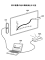
図42は、表示装置2の他の構成例を示す図である。図42では、通常のホワイトボード413の上辺にプロジェクター411が設置されている。このプロジェクター411が表示装置2に相当する。通常のホワイトボード413とは、タッチパネルと一体のフラットパネルディスプレーではなく、ユーザーがマーカーで直接、手書きするホワイトボードである。なお、ホワイトボードは黒板でもよく、映像を投影するだけの広さの平面であればよい。
Figure 42 is a diagram showing another example of the configuration of the
プロジェクター411は超短焦点の光学系を有しており、10cm程度から歪みの少ない映像をホワイトボード413に投影できる。この映像は、無線又は有線で接続されたPCから送信されてもよいし、プロジェクター411が記憶していてもよい。
The
ユーザーは専用の電子ペン2501を使ってホワイトボード413に手書きする。電子ペン2501は、ユーザーが手書きのためにホワイトボード413に押しつけるとスイッチがONになり発光する発光部を例えば先端部に有している。光の波長は近赤外や赤外なのでユーザーの目には見えない。プロジェクター411はカメラを有しており、発光部を撮像して画像を解析し電子ペン2501の方向を特定する。また、電子ペン2501は発光と共に音波を発信しており、プロジェクター411は音波の到達時間により距離を算出する。プロジェクター411は、方向と距離により電子ペン2501の位置を特定できる。電子ペン2501の位置には手書きされたデータが描画(投影)される。
The user writes by hand on the
プロジェクター411はメニュー430を投影するので、ユーザーが電子ペン2501でボタンを押下すると、プロジェクター411が電子ペン2501の位置とスイッチのON信号により押下されたボタンを特定する。例えば、保存ボタン431が押下されると、ユーザーが手書きした手書きされたデータ(座標点列)がプロジェクター411で保存される。プロジェクター411は、予め定められたサーバー412又はUSBメモリ2600等に手書き情報を保存する。手書き情報はページごとに保存されている。画像データではなく座標のまま保存されるので、ユーザーが再編集することができる。ただし、本実施形態では操作コマンドを手書きで呼び出せるのでメニュー430は表示されなくてもよい。
The
<<表示装置の別の構成例2>>
図43は、表示装置2の他の構成例を示す図である。図43の例では、表示装置2は、端末装置600、画像投影装置700A、及び、ペン動作検出装置810を有する。
<<Another Configuration Example 2 of the Display Device>>
Fig. 43 is a diagram showing another example of the configuration of the
端末装置600は、画像投影装置700A及びペン動作検出装置810と有線で接続されている。画像投影装置700Aは、端末装置600により入力された画像データをスクリーン800に投影させる。
The
ペン動作検出装置810は、電子ペン820と通信を行っており、スクリーン800の近傍における電子ペン820の動作を検出する。具体的には、電子ペン820は、スクリーン800上において、電子ペン820が示している点を示す座標情報を検出し(検出方法は図42と同様でよい)、端末装置600へ送信する。
The pen
端末装置600は、ペン動作検出装置810から受信した座標情報に基づき、電子ペン820によって入力される手書きデータの画像データを生成し、画像投影装置700Aによって手書きデータの画像をスクリーン800に描画させる。
Based on the coordinate information received from the pen
また、端末装置600は、画像投影装置700Aに投影させている背景画像と、電子ペン820によって入力された手書データの画像とを合成した重畳画像を示す重畳画像データを生成する。
In addition, the
<<表示装置の別の構成例3>>
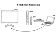
図44は、表示装置2の構成例を示す図である。図44の例では、表示装置2は、端末装置600と、ディスプレー800Aと、ペン動作検出装置810Aとを有する。
<<Another Configuration Example 3 of the Display Device>>
Fig. 44 is a diagram showing an example of the configuration of the
ペン動作検出装置810Aは、ディスプレー800Aの近傍に配置され、ディスプレー800A上に、電子ペン820Aが示している点を示す座標情報を検出し(検出方法は図42と同様でよい)、端末装置600へ送信する。なお、図44の例では、電子ペン820Aは、端末装置600によってUSBコネクタを介して充電されても良い。
The pen
端末装置600は、ペン動作検出装置810Aから受信した座標情報に基づき、電子ペン820Aによって入力される手書データの画像の画像データを生成し、ディスプレー800Aに表示させる。
Based on the coordinate information received from the pen
<<表示装置の別の構成例4>>
図45は、表示装置2の構成例を示す図である。図45の例では、表示装置2は、端末装置600と、画像投影装置700Aとを有する。
<<Another Configuration Example 4 of the Display Device>>
Fig. 45 is a diagram showing a configuration example of the
端末装置600は、電子ペン820Bと無線通信(Bluetooth(登録商標)等)を行って、スクリーン800上において電子ペン820Bが示す点の座標情報を受信する。座標情報は、スクリーン800に形成された微小な位置情報を電子ペン820Bが読み取ってもよいし、スクリーン800から座標情報を受信してもよい。
The
そして、端末装置600は、受信した座標情報に基づき、電子ペン820Bにより入力される手書データの画像の画像データを生成し、画像投影装置700Aに手書データの画像を投影させる。
Then, based on the received coordinate information, the
また、端末装置600は、画像投影装置700Aに投影させている背景画像と、電子ペン820Bによって入力された手書データの画像とを合成した重畳画像を示す重畳画像データを生成する。
In addition, the
以上のように、上記した各実施形態は、様々なシステム構成において適用することができる。 As described above, each of the above-mentioned embodiments can be applied to various system configurations.
<その他の適用例>
以上、本発明を実施するための最良の形態について実施例を用いて説明したが、本発明はこうした実施例に何等限定されるものではなく、本発明の要旨を逸脱しない範囲内において種々の変形及び置換を加えることができる。
<Other application examples>
The above describes the best mode for carrying out the present invention using examples, but the present invention is not limited to these examples in any way, and various modifications and substitutions can be made within the scope that does not deviate from the gist of the present invention.
例えば、本実施形態では、行に関する編集を主に説明したが、ユーザーは列についても同様に編集できる。列についてはタイトル列が左端にある。 For example, while this embodiment has been described primarily as editing rows, the user can edit columns in the same way. For columns, the title column is at the left end.
また、本実施形態では、手書きデータの入力を主に説明したが、表示装置は手書きデータを文字認識することができる。表内の描画オブジェクトは手書きデータでも文字列でもよい。 In addition, although the present embodiment has been described mainly with respect to input of handwritten data, the display device can perform character recognition of handwritten data. Drawing objects in a table may be handwritten data or character strings.
また、本実施形態では、電子黒板として使用できる表示装置を説明したが、表示装置は画像を表示できればよく、例えばデジタルサイネージなどでもよい。また、ディスプレーでなくプロジェクターが表示データを表示してもよい。この場合、本実施形態ではペン先の座標をタッチパネルで検知する方法でペンの座標を検出したが、表示装置2は、ペン先の座標を超音波により検出してもよい。ペンは発光と共に超音波を発信しており、表示装置2は超音波の到達時間により距離を算出する。表示装置2は、方向と距離によりペンの位置を特定できる。ペンの軌跡をストロークとしてプロジェクターが描画(投影)する。
In addition, in this embodiment, a display device that can be used as an electronic whiteboard has been described, but the display device may be any device capable of displaying images, such as digital signage. Also, a projector may display display data instead of a display. In this case, in this embodiment, the coordinates of the pen are detected by detecting the coordinates of the pen tip using a touch panel, but the
また、本実施形態では電子黒板を一例として説明したが、タッチパネルを有する情報処理装置であれば好適に適用できる。電子黒板と同様の機能を有する装置を、電子ホワイトボード、電子情報ボード、インタラクティブボードなどともいう。タッチパネルを搭載した情報処理装置としては、例えば、PJ(Projector:プロジェクター)、デジタルサイネージ等の出力装置、HUD(Head Up Display)装置、産業機械、撮像装置、集音装置、医療機器、ネットワーク家電、ノートPC(Personal Computer)、携帯電話、スマートフォン、タブレット端末、ゲーム機、PDA、デジタルカメラ、ウェアラブルPC又はデスクトップPC等であってもよい。 In addition, although an electronic whiteboard has been described as an example in this embodiment, any information processing device having a touch panel can be suitably applied. A device having the same function as an electronic whiteboard is also called an electronic whiteboard, an electronic information board, an interactive board, etc. Examples of information processing devices equipped with a touch panel include output devices such as PJ (Projector), digital signage, HUD (Head Up Display) devices, industrial machinery, imaging devices, sound collection devices, medical equipment, network home appliances, notebook PCs (Personal Computers), mobile phones, smartphones, tablet terminals, game consoles, PDAs, digital cameras, wearable PCs, or desktop PCs.
また、図5などの構成例は、表示装置2による処理の理解を容易にするために、主な機能に応じて分割したものである。処理単位の分割の仕方や名称によって本願発明が制限されることはない。表示装置2の処理は、処理内容に応じて更に多くの処理単位に分割することもできる。また、1つの処理単位が更に多くの処理を含むように分割することもできる。
The configuration examples in FIG. 5 and the like are divided according to main functions to make it easier to understand the processing by the
また、表示装置2が単体で本実施形態の機能を有する場合を説明したが、表示装置2の機能をサーバーが提供してもよい。この場合、表示装置2とサーバーがネットワークを介して通信する。表示装置2は手書きデータを表示すると共にサーバーに送信し、サーバーが文字認識や表機能などを提供する。
Although the
また、本実施形態において、比較の対象として閾値が例示されていたとしても閾値は例示された値には限定されない。このため、本実施形態では、全ての閾値に関し、閾値未満と閾値以下という記載は同等の意味を持ち、閾値超過と閾値以上という記載は同等の意味を持つ。例えば、閾値を11とした場合の閾値未満という記載は閾値が10である場合の閾値以下と同等の意味を持つ。また、閾値を10とした場合の閾値超過という記載は閾値が11である場合の閾値以上と同等の意味を持つ。 In addition, in this embodiment, even if a threshold is exemplified as an object of comparison, the threshold is not limited to the exemplified value. For this reason, in this embodiment, for all thresholds, the descriptions "less than threshold" and "below threshold" have the same meaning, and the descriptions "exceeding threshold" and "above threshold" have the same meaning. For example, the description "less than threshold" when the threshold is 11 has the same meaning as "below threshold" when the threshold is 10. Furthermore, the description "exceeding threshold" when the threshold is 10 has the same meaning as "below threshold" when the threshold is 11.
また、上記で説明した実施形態の各機能は、一又は複数の処理回路によって実現することが可能である。ここで、本明細書における「処理回路」とは、電子回路により実装されるプロセッサのようにソフトウェアによって各機能を実行するようプログラミングされたプロセッサや、上記で説明した各機能を実行するよう設計されたASIC(Application Specific Integrated Circuit)、DSP(digital signal processor)、FPGA(field programmable gate array)や従来の回路モジュール等のデバイスを含むものとする。 Furthermore, each function of the embodiments described above can be realized by one or more processing circuits. Here, the term "processing circuit" in this specification includes a processor programmed to execute each function by software, such as a processor implemented by an electronic circuit, and devices such as an ASIC (Application Specific Integrated Circuit), DSP (digital signal processor), FPGA (field programmable gate array), and conventional circuit modules designed to execute each function described above.
接触位置検出部40は受付手段の一例である。オブジェクト選択部44は選択受付手段の一例である。表オブジェクト管理部43は制御手段の一例である。記号認識部48は認識手段の一例である。
The contact
2 表示装置 2 Display device
Claims (9)
入力手段により手書きデータの入力を受け付ける受付手段と、
前記表の行又は列の選択を前記手書きデータにより受け付ける選択受付手段と、
前記選択受付手段により前記表の行又は列が選択された場合、ユーザー操作に応じて、選択された前記表の行又は列に関する前記表の編集を行う制御手段と、を有し、
前記制御手段は、前記選択受付手段が選択を受け付けた行又は列の付近に行又は列を追加するためのボタンを表示し、
前記受付手段が前記ボタンの押下を受け付けた場合、前記選択受付手段が選択を受け付けた行又は列の前又は後に、行又は列を追加する、
表示装置。 A display device for displaying a handwritten table,
a receiving means for receiving handwritten data input by an input means;
a selection receiving means for receiving a selection of a row or column of the table by the handwritten data;
a control means for editing the table with respect to the selected row or column of the table in response to a user operation when a row or column of the table is selected by the selection receiving means,
the control means displays a button for adding a row or a column near the row or column selected by the selection receiving means;
When the reception means receives a press of the button, a row or a column is added before or after the row or column selected by the selection reception means.
Display device.
前記選択受付手段が選択を受け付けた行又は列の隣に手書きされた前記手書きデータを、予め定められている記号に前記認識手段が認識した場合、前記制御手段は、前記選択受付手段が選択を受け付けた行又は列の前又は後に、行又は列を追加する請求項1又は2に記載の表示装置。 a recognition unit that recognizes the handwritten data received by the reception unit,
3. The display device according to claim 1 or 2, wherein when the recognition means recognizes the handwritten data handwritten next to a row or column for which the selection accepting means has accepted a selection as a predetermined symbol, the control means adds a row or column before or after the row or column for which the selection accepting means has accepted a selection.
前記選択受付手段が選択を受け付けた行又は列の境界に手書きされた前記手書きデータを、予め定められている記号に前記認識手段が認識した場合、前記制御手段は、前記境界に行又は列を追加する請求項1又は2に記載の表示装置。 a recognition unit that recognizes the handwritten data received by the reception unit,
3. The display device according to claim 1, wherein when the recognition means recognizes the handwritten data handwritten at the boundary of a row or column for which the selection receiving means has accepted a selection as a predetermined symbol, the control means adds a row or column to the boundary.
前記受付手段が前記ボタンの押下を受け付けた場合、前記選択受付手段が選択を受け付けた行又は列を削除する請求項1~4のいずれか1項に記載の表示装置。 the control means displays a button for deleting a row or column near the row or column selected by the selection receiving means;
5. The display device according to claim 1, wherein, when the accepting means accepts pressing of the button, the row or column selected by the selection accepting means is deleted.
前記選択受付手段が選択を受け付けた行又は列の隣に手書きされた前記手書きデータを、予め定められている記号に前記認識手段が認識した場合、前記制御手段は、前記選択受付手段が選択を受け付けた行又は列を削除する請求項1~4のいずれか1項に記載の表示装置。 a recognition unit that recognizes the handwritten data received by the reception unit,
A display device as described in any one of claims 1 to 4, wherein when the recognition means recognizes the handwritten data handwritten next to a row or column for which the selection accepting means has accepted a selection as a predetermined symbol, the control means deletes the row or column for which the selection accepting means has accepted a selection.
前記選択受付手段が選択を受け付けた行又は列を削除する請求項1~4のいずれか1項に記載の表示装置。 When the handwritten data for deleting a row or column selected by the selection receiving means is received by the receiving means,
5. The display device according to claim 1, wherein the row or column for which the selection receiving means has received a selection is deleted.
受付手段が、入力手段により手書きデータの入力を受け付けるステップと、
選択受付手段が、前記表の行又は列の選択を前記手書きデータにより受け付けるステップと、
前記選択受付手段により前記表の行又は列が選択された場合、制御手段が、ユーザー操作に応じて、選択された前記表の行又は列に関する前記表の編集を行うステップと、
前記制御手段が、前記選択受付手段が選択を受け付けた行又は列の付近に行又は列を追加するためのボタンを表示するステップと、
前記受付手段が前記ボタンの押下を受け付けた場合、前記選択受付手段が選択を受け付けた行又は列の前又は後に、行又は列を追加するステップと、
を有する表示方法。 A display method performed by a display device that displays a handwritten table, comprising the steps of:
A step in which a receiving means receives input of handwritten data by an input means;
a selection receiving means for receiving a selection of a row or column of the table by the handwritten data;
a step of, when a row or column of the table is selected by the selection receiving means, editing the table with respect to the selected row or column of the table in response to a user operation by a control means;
a step of the control means displaying a button for adding a row or column near the row or column selected by the selection receiving means;
adding a row or column before or after the row or column selected by the selection receiving means when the receiving means receives a press of the button;
A display method having the following structure:
入力手段により手書きデータの入力を受け付ける受付手段と、
前記表の行又は列の選択を前記手書きデータにより受け付ける選択受付手段と、
前記選択受付手段により前記表の行又は列が選択された場合、ユーザー操作に応じて、選択された前記表の行又は列に関する前記表の編集を行う制御手段、として機能させ、
前記制御手段は、前記選択受付手段が選択を受け付けた行又は列の付近に行又は列を追加するためのボタンを表示し、
前記受付手段が前記ボタンの押下を受け付けた場合、前記選択受付手段が選択を受け付けた行又は列の前又は後に、行又は列を追加する、
プログラム。 A display device for displaying a table created by handwriting,
a receiving means for receiving handwritten data input by an input means;
a selection receiving means for receiving a selection of a row or column of the table by the handwritten data;
when a row or column of the table is selected by the selection receiving means, the control means functions as a control means for editing the table with respect to the selected row or column of the table in response to a user operation;
the control means displays a button for adding a row or a column near the row or column selected by the selection receiving means;
When the reception means receives a press of the button, a row or a column is added before or after the row or column selected by the selection reception means.
program.
Priority Applications (2)
| Application Number | Priority Date | Filing Date | Title |
|---|---|---|---|
| JP2021033451A JP7608874B2 (en) | 2021-03-03 | 2021-03-03 | Display device, display method, and program |
| US17/582,023 US11816327B2 (en) | 2021-03-03 | 2022-01-24 | Display apparatus, method for displaying, and non-transitory recording medium |
Applications Claiming Priority (1)
| Application Number | Priority Date | Filing Date | Title |
|---|---|---|---|
| JP2021033451A JP7608874B2 (en) | 2021-03-03 | 2021-03-03 | Display device, display method, and program |
Publications (2)
| Publication Number | Publication Date |
|---|---|
| JP2022134370A JP2022134370A (en) | 2022-09-15 |
| JP7608874B2 true JP7608874B2 (en) | 2025-01-07 |
Family
ID=83117177
Family Applications (1)
| Application Number | Title | Priority Date | Filing Date |
|---|---|---|---|
| JP2021033451A Active JP7608874B2 (en) | 2021-03-03 | 2021-03-03 | Display device, display method, and program |
Country Status (2)
| Country | Link |
|---|---|
| US (1) | US11816327B2 (en) |
| JP (1) | JP7608874B2 (en) |
Citations (8)
| Publication number | Priority date | Publication date | Assignee | Title |
|---|---|---|---|---|
| US20110078560A1 (en) | 2009-09-25 | 2011-03-31 | Christopher Douglas Weeldreyer | Device, Method, and Graphical User Interface for Displaying Emphasis Animations for an Electronic Document in a Presentation Mode |
| US20110163968A1 (en) | 2010-01-06 | 2011-07-07 | Hogan Edward P A | Device, Method, and Graphical User Interface for Manipulating Tables Using Multi-Contact Gestures |
| US20120013539A1 (en) | 2010-07-13 | 2012-01-19 | Hogan Edward P A | Systems with gesture-based editing of tables |
| US20120173963A1 (en) | 2010-09-21 | 2012-07-05 | Microsoft Corporation | Web page application controls |
| JP2012181708A (en) | 2011-03-01 | 2012-09-20 | Ubiquitous Entertainment Inc | Spreadsheet control program, spreadsheet controller and spreadsheet control method |
| US20140189482A1 (en) | 2012-12-31 | 2014-07-03 | Smart Technologies Ulc | Method for manipulating tables on an interactive input system and interactive input system executing the method |
| US20140372856A1 (en) | 2013-06-14 | 2014-12-18 | Microsoft Corporation | Natural Quick Functions Gestures |
| US20180121074A1 (en) | 2016-10-28 | 2018-05-03 | Microsoft Technology Licensing, Llc | Freehand table manipulation |
Family Cites Families (4)
| Publication number | Priority date | Publication date | Assignee | Title |
|---|---|---|---|---|
| US8773370B2 (en) * | 2010-07-13 | 2014-07-08 | Apple Inc. | Table editing systems with gesture-based insertion and deletion of columns and rows |
| JP5807699B1 (en) | 2014-05-15 | 2015-11-10 | 合同会社Uxイノベーションズ | Information processing apparatus and program |
| JP2016134014A (en) | 2015-01-20 | 2016-07-25 | 株式会社リコー | Electronic information board device, information processing method and program |
| US9965445B2 (en) * | 2015-08-06 | 2018-05-08 | FiftyThree, Inc. | Systems and methods for gesture-based formatting |
-
2021
- 2021-03-03 JP JP2021033451A patent/JP7608874B2/en active Active
-
2022
- 2022-01-24 US US17/582,023 patent/US11816327B2/en active Active
Patent Citations (8)
| Publication number | Priority date | Publication date | Assignee | Title |
|---|---|---|---|---|
| US20110078560A1 (en) | 2009-09-25 | 2011-03-31 | Christopher Douglas Weeldreyer | Device, Method, and Graphical User Interface for Displaying Emphasis Animations for an Electronic Document in a Presentation Mode |
| US20110163968A1 (en) | 2010-01-06 | 2011-07-07 | Hogan Edward P A | Device, Method, and Graphical User Interface for Manipulating Tables Using Multi-Contact Gestures |
| US20120013539A1 (en) | 2010-07-13 | 2012-01-19 | Hogan Edward P A | Systems with gesture-based editing of tables |
| US20120173963A1 (en) | 2010-09-21 | 2012-07-05 | Microsoft Corporation | Web page application controls |
| JP2012181708A (en) | 2011-03-01 | 2012-09-20 | Ubiquitous Entertainment Inc | Spreadsheet control program, spreadsheet controller and spreadsheet control method |
| US20140189482A1 (en) | 2012-12-31 | 2014-07-03 | Smart Technologies Ulc | Method for manipulating tables on an interactive input system and interactive input system executing the method |
| US20140372856A1 (en) | 2013-06-14 | 2014-12-18 | Microsoft Corporation | Natural Quick Functions Gestures |
| US20180121074A1 (en) | 2016-10-28 | 2018-05-03 | Microsoft Technology Licensing, Llc | Freehand table manipulation |
Also Published As
| Publication number | Publication date |
|---|---|
| JP2022134370A (en) | 2022-09-15 |
| US11816327B2 (en) | 2023-11-14 |
| US20220283701A1 (en) | 2022-09-08 |
Similar Documents
| Publication | Publication Date | Title |
|---|---|---|
| JP7556214B2 (en) | Electronic whiteboard, audio playback method, program, and image processing system | |
| US9454257B2 (en) | Electronic system | |
| JP7600781B2 (en) | Display device, display method, and program | |
| JP7559496B2 (en) | Input device, input method, and program | |
| JP7615805B2 (en) | Display device, program, display method, and display system | |
| JP2023034010A (en) | Display device, display system, display control method, and program | |
| JP2021036401A (en) | Display device, display method and program | |
| JP6773977B2 (en) | Terminal device and operation control program | |
| JP7608874B2 (en) | Display device, display method, and program | |
| JP2022057931A (en) | Display device, display method, program | |
| JP2021197024A (en) | Display unit, display method, and program | |
| US11726654B2 (en) | Display apparatus capable of displaying icon corresponding to shape of hand-drafted input, display method, and non-transitory computer-executable medium storing program thereon | |
| US11782594B2 (en) | Display apparatus, display system, and display method | |
| JP7683253B2 (en) | Display device, program, conversion method, and display system | |
| JP7615810B2 (en) | Display device, display method, and program | |
| JP7739733B2 (en) | Display device, display method, program, and display system | |
| JP7613193B2 (en) | Display device, display method, and program | |
| JP7480608B2 (en) | Display device, display method, and program | |
| JP2022087633A (en) | Display device, erasing method switching method, program | |
| JP6821998B2 (en) | Electronic blackboard, program, method | |
| JP7619115B2 (en) | Display device, display method, and program | |
| JP7604974B2 (en) | Display device, display method, and program | |
| US12159029B2 (en) | Display apparatus, display system, display method, and non-transitory recording medium | |
| JP2022146853A (en) | Display device, program, method for display, and display system | |
| KR102149465B1 (en) | Mobile terminal and method for controlling the same |
Legal Events
| Date | Code | Title | Description |
|---|---|---|---|
| A621 | Written request for application examination |
Free format text: JAPANESE INTERMEDIATE CODE: A621 Effective date: 20240119 |
|
| A977 | Report on retrieval |
Free format text: JAPANESE INTERMEDIATE CODE: A971007 Effective date: 20240822 |
|
| A131 | Notification of reasons for refusal |
Free format text: JAPANESE INTERMEDIATE CODE: A131 Effective date: 20240827 |
|
| A521 | Request for written amendment filed |
Free format text: JAPANESE INTERMEDIATE CODE: A523 Effective date: 20241021 |
|
| TRDD | Decision of grant or rejection written | ||
| A01 | Written decision to grant a patent or to grant a registration (utility model) |
Free format text: JAPANESE INTERMEDIATE CODE: A01 Effective date: 20241119 |
|
| A61 | First payment of annual fees (during grant procedure) |
Free format text: JAPANESE INTERMEDIATE CODE: A61 Effective date: 20241202 |
|
| R150 | Certificate of patent or registration of utility model |
Ref document number: 7608874 Country of ref document: JP Free format text: JAPANESE INTERMEDIATE CODE: R150 |