JP7608870B2 - Oil leak detection system - Google Patents
Oil leak detection system Download PDFInfo
- Publication number
- JP7608870B2 JP7608870B2 JP2021031744A JP2021031744A JP7608870B2 JP 7608870 B2 JP7608870 B2 JP 7608870B2 JP 2021031744 A JP2021031744 A JP 2021031744A JP 2021031744 A JP2021031744 A JP 2021031744A JP 7608870 B2 JP7608870 B2 JP 7608870B2
- Authority
- JP
- Japan
- Prior art keywords
- oil
- data
- temperature
- filled cable
- unit
- Prior art date
- Legal status (The legal status is an assumption and is not a legal conclusion. Google has not performed a legal analysis and makes no representation as to the accuracy of the status listed.)
- Active
Links
- 238000001514 detection method Methods 0.000 title claims description 11
- 230000005611 electricity Effects 0.000 claims description 19
- 238000013500 data storage Methods 0.000 description 18
- 238000010801 machine learning Methods 0.000 description 18
- 238000010586 diagram Methods 0.000 description 15
- 238000000034 method Methods 0.000 description 13
- 230000008569 process Effects 0.000 description 8
- 238000005259 measurement Methods 0.000 description 6
- 230000007423 decrease Effects 0.000 description 4
- 238000012549 training Methods 0.000 description 4
- 230000008859 change Effects 0.000 description 3
- 239000000284 extract Substances 0.000 description 3
- 230000006870 function Effects 0.000 description 3
- 238000012545 processing Methods 0.000 description 3
- 230000000694 effects Effects 0.000 description 2
- 238000005516 engineering process Methods 0.000 description 2
- 230000005856 abnormality Effects 0.000 description 1
- 238000004891 communication Methods 0.000 description 1
- 230000006872 improvement Effects 0.000 description 1
- 238000012544 monitoring process Methods 0.000 description 1
- 230000000704 physical effect Effects 0.000 description 1
- 238000000611 regression analysis Methods 0.000 description 1
Images


Landscapes
- Examining Or Testing Airtightness (AREA)
Description
本発明は、油入りケーブルの漏油判定システムに関する。 The present invention relates to a system for determining oil leakage from oil-filled cables.
従来、油入りケーブルの漏油の可能性を判定する技術が知られている。この種の技術が記載されているものとして、特許文献1から特許文献3がある。特許文献1には、漏油していない状態での油入りケーブルの油槽の油量、油圧、電流、及び外気温を使用して油量又は油圧の近似統計関数を求め、該近似統計関数から得られる油量又は油圧値と現時点の油量又は油圧値との差を求め、その差が増加したときに漏油を判定する方法が記載されている。特許文献2には、現在の所定期間の実測油量パターン等と、現在の所定期間と同様の条件のときの過去の所定期間内の実測油量パターンを求め、現在の実測油量パターンと過去の実測油量パターンとを比較して油入りケーブルの漏油を検知する方法が記載されている。特許文献3には、油量、油圧、またはガス圧を目的変量、一または二以上の温度種別を説明変量として多重回帰分析によって予測式を算出し、該予測式を用いて油入りケーブルの異常を監視する装置が記載されている。
Conventionally, there are known techniques for determining the possibility of oil leakage from oil-filled cables.
しかしながら、特許文献1及び2の技術では、所定期間における油量又は油圧の増減を比較した後に漏油の判定を行うので、漏油量が少ないほど判定に時間がかかる。また、特許文献3に記載の技術では、油量又は油圧を求めるために説明変量として用いられた温度種別等のパラメータ以外の要素による影響が判定結果に反映されない可能性があり、より正確に漏油の可能性を判定するという点で改善の余地がある。
However, in the technologies of
本発明は、油入りケーブルの漏油の可能性をより正確かつ迅速に判定できる漏油判定システムを提供することを目的とする。 The present invention aims to provide an oil leakage detection system that can more accurately and quickly determine the possibility of oil leakage from oil-filled cables.
本発明は、油入りケーブルの漏油の可能性を判定する漏油判定システムであって、過去の年間を通した気温データ及び前記油入りケーブルの油槽の油レベルのデータを記憶する記憶部と、気温と前記油入りケーブルの油槽の油レベルを取得する取得部と、前記取得部によって取得される気温と、該気温の取得時から過去の同じ時期の気温データとの差に基づいて、所定の閾値範囲を設定する閾値設定部と、前記取得部によって取得される前記油レベルと、該油レベルの取得時から過去の同じ時期の前記油レベルのデータとの差が前記閾値範囲から外れた場合に、漏油の可能性があると判定する漏油判定部と、を備える。 The present invention is an oil leakage determination system for determining the possibility of oil leakage from an oil-filled cable, and includes a memory unit for storing air temperature data throughout the past year and data on the oil level in the oil tank of the oil-filled cable, an acquisition unit for acquiring air temperature and the oil level in the oil tank of the oil-filled cable, a threshold setting unit for setting a predetermined threshold range based on the difference between the air temperature acquired by the acquisition unit and the air temperature data for the same period in the past from the time the air temperature was acquired, and an oil leakage determination unit for determining that there is a possibility of oil leakage when the difference between the oil level acquired by the acquisition unit and the data on the oil level for the same period in the past from the time the oil level was acquired falls outside the threshold range.
前記記憶部は、過去の年間を通した前記油入りケーブルに流れる電力量データを更に記憶し、前記取得部は、前記油入りケーブルに流れる電力量を更に取得し、前記閾値設定部は、前記記憶部に記憶された電力量データと前記取得部によって取得される電力量に基づいて前記閾値範囲を補正する。 The memory unit further stores data on the amount of electricity flowing through the oil-filled cable throughout the past year, the acquisition unit further acquires the amount of electricity flowing through the oil-filled cable, and the threshold setting unit corrects the threshold range based on the amount of electricity data stored in the memory unit and the amount of electricity acquired by the acquisition unit.
前記油レベルは、少なくとも油量又は油圧の何れかである。 The oil level is at least either the oil volume or the oil pressure.
少なくとも前記油入りケーブルの油槽の油量データと前記油槽の油量計の目盛りの画像データの組又は前記油入りケーブルの油槽の油圧データと前記油槽の油圧計の目盛りの画像データとの組を教師データとして教師あり学習を行うことによって構築された学習モデルを用いて、前記油入りケーブルの油槽の油レベルを特定する油レベル特定部と、を更に備える。 The device further includes an oil level determination unit that determines the oil level of the oil tank of the oil-filled cable by using a learning model constructed by performing supervised learning using as teacher data at least a set of oil volume data of the oil tank of the oil-filled cable and image data of the scale of the oil gauge of the oil tank, or a set of oil pressure data of the oil tank of the oil-filled cable and image data of the scale of the oil pressure gauge of the oil tank.
本発明によれば、油入りケーブルの漏油の可能性をより正確かつ迅速に判定できる漏油判定システムを提供できる。 The present invention provides an oil leakage detection system that can more accurately and quickly determine the possibility of oil leakage from an oil-filled cable.
以下、本発明の実施形態について、図面を参照しながら説明する。ただし、本発明は以下の実施形態に限定されるものではない。 The following describes an embodiment of the present invention with reference to the drawings. However, the present invention is not limited to the following embodiment.
本実施形態に係る漏油判定システム1は、油入りケーブルの漏油の可能性を判定するシステムである。図1は、漏油判定システム1の電気的な構成を示すブロック図である。
The oil
油入りケーブルは、その内側に絶縁油が充填される電力ケーブル(いわゆるOFケーブル)である。油入りケーブルは、絶縁油が貯留される油槽(図示省略)に接続される。油槽内の絶縁油の量である油レベルは、油入りケーブルの損傷等によって油入りケーブルの漏油が発生した場合に減少する。 An oil-filled cable is a power cable (a so-called OF cable) whose inside is filled with insulating oil. The oil-filled cable is connected to an oil tank (not shown) in which the insulating oil is stored. The oil level, which is the amount of insulating oil in the oil tank, decreases when the oil-filled cable leaks due to damage to the oil-filled cable, etc.
本実施形態の漏油判定システム1は、油入りケーブルの油槽の油量や油圧等の油レベルを含む情報を取得して漏油の可能性を判定する。漏油判定システム1は、記憶部20と、制御部10と、を備える。
The oil
記憶部20は、過去の油入りケーブルの油槽の油レベルのデータ(以下、油レベルデータ)と、該油レベルデータの取得時における電力量データ及び気温データを記憶する。記憶部20は、油レベルデータ記憶部21と、電力量データ記憶部22と、気温データ記憶部23とを備える。
The
油レベルデータ記憶部21は、油量データ記憶部211と、油圧データ記憶部212を有する。本実施形態では、油量データ記憶部211及び油圧データ記憶部212には、過去の複数年間の月毎の油入りケーブルの油槽の油レベルが記憶される。具体的には、油量データ記憶部211には、過去の複数年間の月毎の油量データが記憶される。油圧データ記憶部212には、過去の複数年間の月毎の油圧データが記憶される。
The oil level
電力量データ記憶部22には、過去の年間を通した電力量データが記憶される。具体的には、油レベルデータ記憶部21に記憶された各油レベルデータの取得時の電力量データが記憶される。即ち、電力量データ記憶部22には、過去の複数年間の月毎の電力量データが記憶される。また、電力量データ記憶部22に記憶される電力量データは、油入りケーブル全体を流れる電力量の平均であってもよく、油入りケーブルのうち一部の区間を流れる電力量であってもよい。
The power amount
気温データ記憶部23には、過去の年間を通した気温データが記憶される。具体的には、油レベルデータ記憶部21に記憶された各油レベルデータの取得時の気温データが記憶される。即ち、気温データ記憶部23には、過去の複数年間の月毎の気温データが記憶される。記憶部20は、記憶された油レベルデータに対応する電力量データと、気温データを互いに紐付けて記憶する。
The temperature
制御部10は、漏油判定システム1の全体を制御する部分であり、各種プログラムを、ROM、RAM、フラッシュメモリ又はハードディスク(HDD)等の記憶領域から適宜読み出して実行することにより、本実施形態における各種機能を実現している。制御部10は、CPUであってよい。
The
制御部10は、取得部11と、油レベル特定部12と、閾値設定部13と、漏油判定部14と、警報発生部15を備える。
The
取得部11は、油入りケーブルの油槽の油レベルと、該油レベルの取得時における電力量及び気温を取得する。取得部11は、油レベル取得部111と、電力量取得部112と、気温取得部113を有する。
The
油レベル取得部111は、油入りケーブルの油槽の油量や油圧等の油レベルを取得する。油レベル取得部111によって取得される油レベルとしては、油入りケーブルの油槽等に設けられたセンサから送信された油レベルであってもよく、後述する油レベル特定部12から送信された油レベルであってもよい。または、油槽の油量計や油圧計の目盛りを確認した作業者によって入力され、制御部10に送信された油レベルであってもよい。
The oil
電力量取得部112は、油入りケーブルに流れる電力量を取得する。電力量取得部112によって取得される電力量としては、1本の油入りケーブル全体を流れる電力量の平均値であってもよく、1本の油入りケーブルのうち一部の区間を流れる電力量であってもよい。
The power
気温取得部113は、油入りケーブルが布設される地上の気温を取得する。気温取得部113によって取得される気温としては、現地の外気温を測定する温度センサや温度計から得られる値であってもよく、気象観測所の発表値であってもよい。なお、取得部11は、油レベルと、電力量と、気温を略同じタイミングで取得する。
The air
油レベル特定部12は、後述する機械学習装置30によって構築された学習データを用いて、油入りケーブルの油槽の油レベルを特定する。油レベル特定部12は、機械学習装置30によって構築された学習データと、油量計や油圧計の画像データに基づいて油レベルを特定する。油レベル特定部12によって特定された油レベルは、油レベル取得部111に送信される。油レベル特定部12による油レベルを特定する処理の詳細については後述する。
The oil
閾値設定部13は、気温取得部113によって取得される気温と、気温データ記憶部23に記憶された気温データとの差に基づいて所定の閾値範囲を設定する。具体的には、閾値設定部13は、気温取得部113によって取得される気温と、該気温の取得時から過去の同じ時期の気温データとの差に基づいて、油レベル取得部111によって取得される油レベルに関する所定の閾値範囲を設定する。本明細書において「同じ時期」とは、同じ季節、同じ月、又は異なる月であっても月日の差が1ヵ月未満の期間を意味する。過去の同じ時期の気温データとしては、過去の同じ時期の任意の日時の気温であってもよく、過去の同じ時期の任意の一日の平均気温であってもよく、過去の同じ時期の一月の平均気温であってもよい。
The
閾値設定部13によって設定される閾値範囲は、気温取得部113によって取得される気温と過去の気温データとの差が大きいほどその範囲が広くなるように設定される。
The threshold range set by the
本実施形態では、閾値設定部13は、閾値範囲の設定に用いられる気温データに紐づく電力量データと、電力量取得部112によって取得される電力量に基づいて閾値範囲を補正する。具体的には、閾値設定部13は、電力量取得部112によって取得される電力量が所定の値よりも高い場合は、閾値範囲の設定に用いた気温よりも高い気温を用いて設定された範囲になるように閾値範囲を補正し、反対に電力量が所定の値よりも低い場合は、閾値範囲の設定に用いた気温よりも低い気温を用いて設定された範囲になるように閾値範囲を補正する。そして、閾値設定部13は、閾値範囲の設定に用いた気温データに紐づく電力量データが所定の値よりも高い場合は、閾値範囲の設定に用いた気温データよりも高い気温データを用いて設定された範囲になるように閾値範囲を補正し、反対に電力量データが所定の値よりも低い場合は、閾値範囲の設定に用いた気温データよりも低い気温データを用いて設定された範囲になるように閾値範囲を補正する。
In this embodiment, the
漏油判定部14は、油レベル取得部111によって取得される油レベルと油レベルデータ記憶部21に記憶された油レベルデータとの差と、閾値設定部13によって設定され、補正された閾値範囲に基づいて油入りケーブルの漏油の可能性を判定する。具体的には、漏油判定部14は、油レベル取得部111によって取得される油レベルと該油レベルの取得時から過去の同じ時期の油レベルデータとの差が、閾値設定部13によって設定され、補正された閾値範囲から外れた場合に油入りケーブルの漏油の可能性があると判定する。なお、閾値範囲の設定に用いられる油レベルデータは、閾値範囲の設定に用いられる気温データに紐づいたデータである。
The oil
警報発生部15は、漏油判定部14が油入りケーブルの漏油の可能性があると判定した場合に警報を発生する。警報の種類は、特に限定されない。例えば、ブザーやスピーカーを用いて警報音を鳴らしてもよく、LED等の照明器具を用いて光を発光させてもよく、漏油の発生を警告するメッセージをディスプレイに表示してもよい。
The
漏油判定システム1が漏油の判定を行うために用いる油レベルデータ、電力量データ、及び気温データは、例えば、取得部11による油レベル、電力量、及び気温の取得時から1年前のものであってもよい。取得時から年数が経過していない1年前のデータを漏油の判定に用いることで、油入りケーブルの設備や絶縁油の使用年数による漏油判定時と過去の漏油の物性の差を低減でき、より正確に漏油の可能性を判定できる。
The oil level data, power data, and temperature data used by the oil
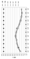
次に、年間を通した油入りケーブルの油槽内の油量の推移と、油量と気温の関係について説明する。図2は、平成25年度から平成29年度の年間を通した油入りケーブルの油槽の油量(L)を示す図である。図2の縦軸は油量(L)を示し、横軸は油量を測定した月を示している。図3は、平成28年度と平成29年度の年間を通した気温(℃)と油入りケーブルの油槽の油量を示す図である。図3の左側の縦軸は油量(L)を示し、右側の縦軸は油量測定時の気温(℃)を示し、横軸は油量を測定した月を示している。なお、図2及び図3において、二点鎖線は油入りケーブルの油槽に貯留できる油量の上限値と油量の下限値を示している。図3において実線は平成29年度の油量及び気温の推移を示し、破線は平成28年度の油量及び気温の推移を示している。また、図2及び図3に示す油量は、各月に1度、所定の日に測定された値である。 Next, we will explain the change in the amount of oil in the oil tank of the oil-filled cable throughout the year and the relationship between the amount of oil and the temperature. Figure 2 is a diagram showing the amount of oil (L) in the oil tank of the oil-filled cable throughout the year from fiscal year 2013 to fiscal year 2017. The vertical axis of Figure 2 shows the amount of oil (L), and the horizontal axis shows the month when the amount of oil was measured. Figure 3 is a diagram showing the temperature (℃) and the amount of oil in the oil tank of the oil-filled cable throughout the year from fiscal year 2016 to fiscal year 2017. The vertical axis on the left side of Figure 3 shows the amount of oil (L), the vertical axis on the right side shows the temperature (℃) when the amount of oil was measured, and the horizontal axis shows the month when the amount of oil was measured. In Figures 2 and 3, the two-dot chain lines show the upper limit and lower limit of the amount of oil that can be stored in the oil tank of the oil-filled cable. In Figure 3, the solid line shows the change in the amount of oil and the temperature in fiscal year 2017, and the dashed line shows the change in the amount of oil and the temperature in fiscal year 2016. Additionally, the oil levels shown in Figures 2 and 3 were measured on a specific day once each month.
図2に示すように、年間の油量の推移は各年で同様の傾向になる。図2に示すように、各年の同じ月の油量は多少のズレはあるものの、同様の値になることが多い。この1つの要因として、気温が高い夏場は油が膨張するので油量が増え、気温が低い冬場は油量が減少することが考えられる。 As shown in Figure 2, the annual oil volume trend follows a similar pattern each year. As shown in Figure 2, the oil volume for the same month each year tends to be similar, although there is some variation. One possible reason for this is that oil expands in the summer when temperatures are high, increasing the volume, and oil volume decreases in the winter when temperatures are low.
図3に示すように、同じ月に測定された油量でも差が比較的大きい場合がある。例えば、平成28年度と平成29年度の5月の油量を比べると、平成29年度の油量の方が平成28年度の油量に比べて約14L高くなっている。これは測定時の平成29年度の気温が平成28年度の気温に比べて約14℃高くなっているためであると考えられる。また、平成28年度と平成29年度の10月の油量を比べると、平成29年度の油量の方が平成28年度の油量に比べて約18L低くなっている。これは測定時の平成29年度の気温が平成28年度の気温に比べて約10℃低くなっているためであると考えられる。 As shown in Figure 3, there can be relatively large differences in oil volumes measured in the same month. For example, when comparing the oil volumes in May of FY2016 and FY2017, the oil volume in FY2017 is approximately 14 L higher than the oil volume in FY2016. This is thought to be because the temperature in FY2017 at the time of measurement was approximately 14°C higher than the temperature in FY2016. Also, when comparing the oil volumes in October of FY2016 and FY2017, the oil volume in FY2017 is approximately 18 L lower than the oil volume in FY2016. This is thought to be because the temperature in FY2017 at the time of measurement was approximately 10°C lower than the temperature in FY2016.
一方で、同じ年度での月毎の油量の推移を比べると、気温による影響はあるものの、基本的に8月に近づくほど油量が高くなり、2月に近づくほど油量が低くなる傾向にある。平成28年度4月の油量測定時の気温は5月の気温によりも約2℃高いが、平成28年度4月の油量は5月の油量よりも低くなっている。また、平成28年1月の油量測定時の気温は2月の気温よりも約2℃低いが、平成28年度1月の油量は2月の油量よりも低くなっている。よって、測定時の気温による影響はあるものの、基本的に測定時期による影響を強く受けると考えられる。これは、電力の使用頻度等の季節毎の電力使用者の活動状況や生活状況が油量の増減に影響しているためであると考えられる。 On the other hand, when comparing the monthly oil volume trends in the same fiscal year, although there is an influence from temperature, the oil volume generally tends to be higher as it gets closer to August and lower as it gets closer to February. The temperature when the oil volume was measured in April 2016 was about 2°C higher than the temperature in May, but the oil volume in April 2016 was lower than the oil volume in May. Also, the temperature when the oil volume was measured in January 2016 was about 2°C lower than the temperature in February, but the oil volume in January 2016 was lower than the oil volume in February. Therefore, although there is an influence from the temperature at the time of measurement, it is thought that it is basically strongly influenced by the time of measurement. This is thought to be because the activity and living conditions of electricity users in each season, such as the frequency of electricity use, affect the increase or decrease in oil volume.
本実施形態では、油レベルの取得時と過去の同じ時期の気温の差を考慮しつつ、油レベル取得部111による油レベルと、該油レベルの取得時から過去の同じ時期の油レベルデータとの差に基づいて閾値範囲を設定しているので、より正確かつ迅速に漏油の可能性を判定できる。
In this embodiment, the threshold range is set based on the difference between the oil level obtained by the oil
次に、漏油判定システム1による油入りケーブルの漏油判定の処理の一例について図4を参照しながら説明する。図4は、漏油判定システム1による漏油判定の処理の流れを示すフローチャートである。
Next, an example of the process of oil leakage detection for an oil-filled cable by the oil
ステップS1において、取得部11は、油入りケーブルの油槽の油レベルと、油入りケーブルに流れる電力量と、気温を取得する。本実施形態では、油レベルは、油レベル取得部111が油レベル特定部12からの情報を受信することによって取得される。
In step S1, the
ステップS2において、閾値設定部13は、記憶部20に格納された油レベルデータと、電力量データと、気温データを抽出する。具体的には、閾値設定部13は、ステップS1における油レベルと、電力量と、気温の取得時から過去の同じ時期の互いに紐づく油レベルデータと、電力量データと、気温データの組を1組抽出する。
In step S2, the
ステップS3において、閾値設定部13は、ステップS1で取得された気温をステップS2で抽出された気温データで差し引くことによって気温差Xを算出する。
In step S3, the
ステップS4において、閾値設定部13は、ステップS3で算出された気温差Xに基づいて、油レベルに対する閾値範囲Z1を設定する。
In step S4, the
ステップS5において、閾値設定部13は、ステップS1で取得された電力量及びステップS2で抽出された電力量データに基づいてステップS4で設定された閾値範囲Zを補正する。
In step S5, the
ステップS3~S5の処理と並行してステップS6の処理が実行される。ステップS6において、漏油判定部14は、ステップS1で取得された油レベルをステップS2で抽出された油レベルデータで差し引くことによって油レベル差Yを算出する。
The process of step S6 is executed in parallel with the processes of steps S3 to S5. In step S6, the oil
ステップS7において、漏油判定部14は、ステップS6で算出された油レベル差YとステップS5で補正された閾値範囲Z2を比較する。具体的には、漏油判定部14は、油レベル差Yが補正された閾値範囲Z2内である場合(ステップS7でYes)、漏油の可能性はないと判断し、漏油判定の処理を完了する。一方、漏油判定部14は、油レベル差Yが閾値範囲Z2から外れたと判定した場合(ステップS7でNo)、漏油の可能性があると判断し、処理をステップS8に進める。
In step S7, the oil
ステップS7の処理によって漏油判定部14が油入りケーブルの漏油が発生していると判定すると、ステップS8において警報発生部15は警報を発生する。警報発生部15が警報を発生させると、制御部10は漏油判定の処理を完了する。
When the oil
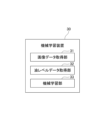
次に、機械学習装置30について図5から図7Bを参照しながら説明する。図5は、機械学習装置30の機能ブロック図である。図6A及び図6Bは、教師データである油量データと画像データを示す図である。図7A及び図7Bは、教師データである油圧データと画像データを示す図である。
Next, the
機械学習装置30は、漏油判定システム1とネットワーク(図示省略)で接続されており、ネットワークを介して相互に通信を行うことが可能である。ネットワークは、例えば、LAN(LOCAL Area Network)や、インターネット、公衆電話網、あるいは、これらの組み合わせである。ネットワークにおける具体的な通信方式や、有線接続及び無線接続のいずれであるか等については、特に限定されない。なお、機械学習装置30と漏油判定システム1とは、ネットワークを用いた通信ではなく、接続部を介して直接接続してもよい。
The
図5に示すように、機械学習装置30は、画像データ取得部31と、油レベルデータ取得部32と、機械学習部33を備える。
As shown in FIG. 5, the
画像データ取得部31は、例えば、図6A及び図6Bに示すように、油入りケーブルの油槽に設けられた油量計の目盛りを被写体として含む写真である画像データA1,A2を取得する。また例えば、図7A及び図7Bに示すように、画像データ取得部31は、油圧計の目盛りを被写体として含む写真である画像データC1,C2を取得する。
For example, as shown in Figures 6A and 6B, the image
油レベルデータ取得部32は、例えば、図6A及び図6Bに示すように、油入りケーブルの油槽に設けられた油量計の目盛りが示す値を油量データB1,B2として取得する。また例えば、図7A及び図7Bに示すように、油レベルデータ取得部32は、油入りケーブルの油槽に設けられた油圧計の目盛りが示す値を油圧データD1,D2として取得する。
For example, as shown in Figures 6A and 6B, the oil level
機械学習部33は、画像データと油量データとの組又は画像データと油圧データとの組を教師データとして教師あり学習を行うことによって学習モデルを構築する。例えば、機械学習部33は、画像データA1と油量データB1との組や画像データA2と油量データB2との組等の複数の教師データを用いて教師あり学習を行うことによって油量を求めるための学習モデルを構築する。また、機械学習部33は、画像データC1と油圧データD1との組や画像データC2と油圧データD2との組等の複数の教師データを用いて教師あり学習を行うことによって油圧を求めるための学習モデルを構築する。機械学習部33は、構築した学習モデルを漏油判定システム1の油レベル特定部12に送信する。
The
次に、油レベル特定部12による油レベルを特定する処理について説明する。
Next, we will explain the process of determining the oil level by the oil
油レベル特定部12は、機械学習装置30によって構築された学習モデルと、新たに取得された油量計の目盛りの画像データや油圧計の目盛りの画像データに基づいて、油入りケーブルの油槽の油レベルを特定する。具体的には、油レベル特定部12は、カメラ等の画像取得手段(図示省略)によって取得された油量計の目盛りの画像データや油圧計の目盛りの画像データを学習モデルに入力し、学習モデルから出力された油量データや油圧データを油入りケーブルの油レベルとする。そして、油レベル特定部12は、特定した油レベルの情報を油レベル取得部111に送信する。
The oil
以上説明した本実施形態に係る漏油判定システム1によれば、以下のような効果を奏する。
The oil
本実施形態に係る漏油判定システム1は、油入りケーブルの漏油の可能性を判定する漏油判定システム1であって、過去の年間を通した気温データ及び油入りケーブルの油槽の油レベルデータを記憶する記憶部20と、気温と油入りケーブルの油槽の油レベルを取得する取得部11と、取得部11によって取得される気温と、該気温の取得時から過去の同じ時期の気温データとの差に基づいて、所定の閾値範囲を設定する閾値設定部13と、取得部11によって取得される油レベルと、該油レベルの取得時から過去の同じ時期の油レベルデータとの差が閾値範囲から外れた場合に、漏油の可能性があると判定する漏油判定部14と、を備える。
The oil
これにより、現時点と過去の油レベル取得時の気温の差に基づき閾値範囲を設定し、過去の同じ時期の油レベルデータと現時点での油レベルの測定値を比較して漏油を判定するので迅速に漏油の判定の処理を実行できる。また、油レベルに影響を与える気温を考慮しつつ、気候や電力使用者の活動状況や生活状況が類似する現在と過去の同じ時期の油レベルの差から漏油の可能性を判定するので、漏油の判定精度がより向上する。 This allows the system to set a threshold range based on the difference in temperature between the current and previous oil level measurements, and to determine whether or not there is an oil leak by comparing the current oil level measurement with past oil level data from the same time period. This also allows for faster oil leak detection processing. In addition, the system takes into account temperature, which affects oil levels, and determines the possibility of an oil leak from the difference in oil levels between the current and previous times when the climate and the activity and living conditions of electricity users are similar, further improving the accuracy of oil leak detection.
本実施形態において、記憶部20は、過去の年間を通した前記油入りケーブルに流れる電力量データを更に記憶し、取得部11は、油入りケーブルに流れる電力量を更に取得し、閾値設定部13は、記憶部20に記憶された電力量データと取得部11によって取得される電力量に基づいて閾値範囲を補正する。
In this embodiment, the
これにより、油レベルに影響を与える電力量を考慮して閾値範囲が補正されるので、漏油の可能性をより正確に判定できる。 This allows the threshold range to be adjusted to take into account the amount of power that affects the oil level, making it possible to more accurately determine the possibility of an oil leak.
本実施形態において、油レベルは、少なくとも油量又は油圧の何れかである。これにより、油量又は油圧の漏油の可能性をより正確に判定できる。 In this embodiment, the oil level is at least either the oil volume or the oil pressure. This allows for a more accurate determination of the possibility of an oil volume or oil pressure leak.
本実施形態において、漏油判定システム1は、少なくとも油入りケーブルの油槽の油量データと油槽の油量計の目盛りの画像データとの組又は油入りケーブルの油槽の油圧データと油槽の油圧計の目盛りの画像データとの組を教師データとして教師あり学習を行うことによって構築された学習モデルを用いて、油入りケーブルの油槽の油レベルを特定する油レベル特定部12と、を更に備える。
In this embodiment, the oil
これにより、学習モデルを用いて油量計や油圧計の目盛りの画像から油レベルを特定できるので、作業者による油量計や油圧計の目盛りの読み取り作業が不要になり、迅速に正確な値を取得できる。 This makes it possible to use a learning model to identify the oil level from an image of the scale on an oil gauge or oil pressure gauge, eliminating the need for workers to read the scale on the oil gauge or oil pressure gauge and allowing accurate values to be obtained quickly.
以上、本発明の実施形態について説明したが、本発明は、上記実施形態に制限されるものではなく適宜変更が可能である。 The above describes an embodiment of the present invention, but the present invention is not limited to the above embodiment and can be modified as appropriate.
上記実施形態では、漏油判定システム1は、電力量取得部112と電力量データ記憶部22を備えていたが、電力量取得部112と電力量データ記憶部22を備えない構成であってもよい。即ち、漏油判定システム1の閾値設定部13は、閾値範囲の補正を行わない構成であってもよい。
In the above embodiment, the oil
上記実施形態では、漏油判定システム1は、油レベル特定部12を備えていたが、油レベル特定部12を備えない構成であってもよい。
In the above embodiment, the oil
上記実施形態では、記憶部20は、油レベルデータ記憶部21に記憶された各油レベルデータの取得時の電力量を電力量データとして記憶し、気温を気温データとして記憶していたが、例えば、油レベルデータを取得した日の平均電力量を電力量データとして記憶し、平均気温を気温データとして記憶してもよい。
In the above embodiment, the
上記実施形態では、漏油判定システム1は、油レベルと、電力量と、気温の取得時から過去の同じ時期の油レベルデータと、電力量データと、気温データの組を1組抽出して漏油の判定に用いたが、油レベルデータと、電力量データと、気温データの組を複数組用いてもよい。例えば、油レベルと、電力量と、気温の取得時から過去の同じ時期の複数年間の油レベルデータと、電力量データと、気温データの組を複数組抽出し、平均化した油レベルデータと、電力量データと、気温データを用いて漏油の可能性の判定の処理を実行してもよい。
In the above embodiment, the oil
上記実施形態では、記憶部20は過去の複数年間の月毎の油レベルデータ、電力量データ、及び気温データを記憶していたが、記憶部20に記憶された同じ年のデータの個数等は特に限定されない。例えば、過去の複数年間の日毎の油レベルデータ、電力量データ、及び気温データを記録してもよい。
In the above embodiment, the
上記実施形態では、油入りケーブルの油槽の油レベルとして油量や油圧を例に挙げたが、油レベルは油入りケーブルの油槽のガス圧であってもよい。 In the above embodiment, the oil level in the oil tank of the oil-filled cable is exemplified by the oil volume and oil pressure, but the oil level may also be the gas pressure in the oil tank of the oil-filled cable.
1 漏油判定システム
11 取得部
13 閾値設定部
14 漏油判定部
20 記憶部
REFERENCE SIGNS
Claims (4)
過去の年間を通した気温データ及び前記油入りケーブルの油槽の油レベルのデータを記憶する記憶部と、
気温と前記油入りケーブルの油槽の油レベルを取得する取得部と、
前記取得部によって取得される気温と、該気温の取得時から過去の同じ時期の気温データとの差に基づいて、所定の閾値範囲を設定する閾値設定部と、
前記取得部によって取得される前記油レベルと、該油レベルの取得時から過去の同じ時期の前記油レベルのデータとの差が前記閾値範囲から外れた場合に、漏油の可能性があると判定する漏油判定部と、を備える漏油判定システム。 An oil leakage determination system for determining the possibility of oil leakage from an oil-filled cable, comprising:
A storage unit for storing temperature data throughout the past year and data on the oil level of the oil tank of the oil-filled cable;
An acquisition unit for acquiring an air temperature and an oil level in an oil tank of the oil-filled cable;
a threshold setting unit that sets a predetermined threshold range based on a difference between the temperature acquired by the acquisition unit and past temperature data for the same period from the time the temperature was acquired;
An oil leakage determination system comprising: an oil leakage determination unit that determines that there is a possibility of an oil leakage when the difference between the oil level acquired by the acquisition unit and the oil level data for the same past period from the time the oil level was acquired falls outside the threshold range.
前記取得部は、前記油入りケーブルに流れる電力量を更に取得し、
前記閾値設定部は、前記記憶部に記憶された電力量データと前記取得部によって取得される電力量に基づいて前記閾値範囲を補正する請求項1に記載の漏油判定システム。 The storage unit further stores data on the amount of electricity flowing through the oil-filled cable throughout the past year,
The acquisition unit further acquires an amount of power flowing through the oil-filled cable,
The oil leakage determination system according to claim 1 , wherein the threshold setting unit corrects the threshold range based on the power amount data stored in the storage unit and the power amount acquired by the acquisition unit.
Priority Applications (1)
| Application Number | Priority Date | Filing Date | Title |
|---|---|---|---|
| JP2021031744A JP7608870B2 (en) | 2021-03-01 | 2021-03-01 | Oil leak detection system |
Applications Claiming Priority (1)
| Application Number | Priority Date | Filing Date | Title |
|---|---|---|---|
| JP2021031744A JP7608870B2 (en) | 2021-03-01 | 2021-03-01 | Oil leak detection system |
Publications (2)
| Publication Number | Publication Date |
|---|---|
| JP2022132972A JP2022132972A (en) | 2022-09-13 |
| JP7608870B2 true JP7608870B2 (en) | 2025-01-07 |
Family
ID=83229278
Family Applications (1)
| Application Number | Title | Priority Date | Filing Date |
|---|---|---|---|
| JP2021031744A Active JP7608870B2 (en) | 2021-03-01 | 2021-03-01 | Oil leak detection system |
Country Status (1)
| Country | Link |
|---|---|
| JP (1) | JP7608870B2 (en) |
Families Citing this family (2)
| Publication number | Priority date | Publication date | Assignee | Title |
|---|---|---|---|---|
| WO2025208091A1 (en) * | 2024-03-28 | 2025-10-02 | Iot Technologies Llc | Devices, systems and methods for detecting leaks and measuring usage |
| CN120409139B (en) * | 2025-06-30 | 2025-09-12 | 国网山东省电力公司淄博供电公司 | Oil leakage analysis method, system, medium and product for oil-filled cable terminal |
Citations (2)
| Publication number | Priority date | Publication date | Assignee | Title |
|---|---|---|---|---|
| JP2008259313A (en) | 2007-04-04 | 2008-10-23 | Chugoku Electric Power Co Inc:The | Of cable abnormality detector, and method of detecting oil leakage from of cable |
| JP2019124678A (en) | 2018-01-18 | 2019-07-25 | 株式会社日立製作所 | Work terminal, oil leak detection device, and oil leak detection method |
Family Cites Families (3)
| Publication number | Priority date | Publication date | Assignee | Title |
|---|---|---|---|---|
| JP3224108B2 (en) * | 1993-01-11 | 2001-10-29 | 東北電力株式会社 | Oil Leak Determination Method for OF Cable Line |
| JP3257718B2 (en) * | 1993-05-20 | 2002-02-18 | 古河電気工業株式会社 | OF Cable Oil Leak Determination Method |
| JP2001078349A (en) * | 1999-09-03 | 2001-03-23 | Sumitomo Electric Ind Ltd | Oil leak detection method for OF cable line |
-
2021
- 2021-03-01 JP JP2021031744A patent/JP7608870B2/en active Active
Patent Citations (2)
| Publication number | Priority date | Publication date | Assignee | Title |
|---|---|---|---|---|
| JP2008259313A (en) | 2007-04-04 | 2008-10-23 | Chugoku Electric Power Co Inc:The | Of cable abnormality detector, and method of detecting oil leakage from of cable |
| JP2019124678A (en) | 2018-01-18 | 2019-07-25 | 株式会社日立製作所 | Work terminal, oil leak detection device, and oil leak detection method |
Also Published As
| Publication number | Publication date |
|---|---|
| JP2022132972A (en) | 2022-09-13 |
Similar Documents
| Publication | Publication Date | Title |
|---|---|---|
| CN117371337B (en) | Water conservancy model construction method and system based on digital twin | |
| US11719760B2 (en) | Probabilistic determination of transformer end of life | |
| JP6514598B2 (en) | Gas leak detection device and gas leak detection method | |
| CN107066831B (en) | Regional comprehensive environment evaluation method, device and system | |
| CN117709709B (en) | Electric vehicle charging pile fire risk detection method based on infrared identification | |
| US20160369777A1 (en) | System and method for detecting anomaly conditions of sensor attached devices | |
| JP7608870B2 (en) | Oil leak detection system | |
| CN119147141A (en) | Substation SF6 pressure gauge based data acquisition and processing method | |
| CN105046075A (en) | Analyzing-processing method and device for dam quality monitoring data | |
| US20240288129A1 (en) | Methods and internet of things (iot) systems for intelligent detection of cathosic protection in smart gas pipelines | |
| CN103824130A (en) | Grain condition forecasting and early warning method and system based on SVM | |
| CN116202038B (en) | Pipe network leakage event early warning method, device, equipment and medium | |
| CN119375643A (en) | A method and system for detecting insulation detection function | |
| CN119845784B (en) | On-line monitoring method for working state of SF6 density sensor | |
| CN118447393A (en) | Pipeline detection method, system, electronic equipment and storage medium | |
| CN115331403A (en) | Fault data visualization analysis method and system of power supply line | |
| CN120043040A (en) | Intelligent gas pipe network transformation method, system and medium based on supervision Internet of things | |
| CN116716927A (en) | Tower base monitoring methods, devices, computer equipment, storage media and products | |
| KR20180034071A (en) | A measuring method for gas pipelines of risk assessment and measuring system using the same | |
| CN114495438B (en) | Disaster early warning method, system, equipment and storage medium based on multiple sensors | |
| CN113283276A (en) | Linkage thermal imaging self-learning fire point detection method and system | |
| EP2956751B1 (en) | Method and monitoring device for monitoring a structure | |
| Mirats-Tur et al. | Leak detection and localization using models: field results | |
| CN120372417A (en) | Construction method and application of building carbon emission measuring and calculating model | |
| CN117309085A (en) | Temperature control method and system of water meter anti-freezing incubator and water meter anti-freezing incubator |
Legal Events
| Date | Code | Title | Description |
|---|---|---|---|
| A621 | Written request for application examination |
Free format text: JAPANESE INTERMEDIATE CODE: A621 Effective date: 20240208 |
|
| A977 | Report on retrieval |
Free format text: JAPANESE INTERMEDIATE CODE: A971007 Effective date: 20241113 |
|
| TRDD | Decision of grant or rejection written | ||
| A01 | Written decision to grant a patent or to grant a registration (utility model) |
Free format text: JAPANESE INTERMEDIATE CODE: A01 Effective date: 20241119 |
|
| A61 | First payment of annual fees (during grant procedure) |
Free format text: JAPANESE INTERMEDIATE CODE: A61 Effective date: 20241202 |
|
| R150 | Certificate of patent or registration of utility model |
Ref document number: 7608870 Country of ref document: JP Free format text: JAPANESE INTERMEDIATE CODE: R150 |