JP7608858B2 - Vehicle collision avoidance support device - Google Patents
Vehicle collision avoidance support device Download PDFInfo
- Publication number
- JP7608858B2 JP7608858B2 JP2021023272A JP2021023272A JP7608858B2 JP 7608858 B2 JP7608858 B2 JP 7608858B2 JP 2021023272 A JP2021023272 A JP 2021023272A JP 2021023272 A JP2021023272 A JP 2021023272A JP 7608858 B2 JP7608858 B2 JP 7608858B2
- Authority
- JP
- Japan
- Prior art keywords
- vehicle
- avoidance
- steering
- host vehicle
- oncoming
- Prior art date
- Legal status (The legal status is an assumption and is not a legal conclusion. Google has not performed a legal analysis and makes no representation as to the accuracy of the status listed.)
- Active
Links
Images


Classifications
-
- B—PERFORMING OPERATIONS; TRANSPORTING
- B60—VEHICLES IN GENERAL
- B60W—CONJOINT CONTROL OF VEHICLE SUB-UNITS OF DIFFERENT TYPE OR DIFFERENT FUNCTION; CONTROL SYSTEMS SPECIALLY ADAPTED FOR HYBRID VEHICLES; ROAD VEHICLE DRIVE CONTROL SYSTEMS FOR PURPOSES NOT RELATED TO THE CONTROL OF A PARTICULAR SUB-UNIT
- B60W10/00—Conjoint control of vehicle sub-units of different type or different function
- B60W10/20—Conjoint control of vehicle sub-units of different type or different function including control of steering systems
-
- B—PERFORMING OPERATIONS; TRANSPORTING
- B60—VEHICLES IN GENERAL
- B60W—CONJOINT CONTROL OF VEHICLE SUB-UNITS OF DIFFERENT TYPE OR DIFFERENT FUNCTION; CONTROL SYSTEMS SPECIALLY ADAPTED FOR HYBRID VEHICLES; ROAD VEHICLE DRIVE CONTROL SYSTEMS FOR PURPOSES NOT RELATED TO THE CONTROL OF A PARTICULAR SUB-UNIT
- B60W30/00—Purposes of road vehicle drive control systems not related to the control of a particular sub-unit, e.g. of systems using conjoint control of vehicle sub-units
- B60W30/08—Active safety systems predicting or avoiding probable or impending collision or attempting to minimise its consequences
- B60W30/09—Taking automatic action to avoid collision, e.g. braking and steering
-
- B—PERFORMING OPERATIONS; TRANSPORTING
- B60—VEHICLES IN GENERAL
- B60W—CONJOINT CONTROL OF VEHICLE SUB-UNITS OF DIFFERENT TYPE OR DIFFERENT FUNCTION; CONTROL SYSTEMS SPECIALLY ADAPTED FOR HYBRID VEHICLES; ROAD VEHICLE DRIVE CONTROL SYSTEMS FOR PURPOSES NOT RELATED TO THE CONTROL OF A PARTICULAR SUB-UNIT
- B60W30/00—Purposes of road vehicle drive control systems not related to the control of a particular sub-unit, e.g. of systems using conjoint control of vehicle sub-units
- B60W30/08—Active safety systems predicting or avoiding probable or impending collision or attempting to minimise its consequences
- B60W30/095—Predicting travel path or likelihood of collision
- B60W30/0953—Predicting travel path or likelihood of collision the prediction being responsive to vehicle dynamic parameters
-
- B—PERFORMING OPERATIONS; TRANSPORTING
- B60—VEHICLES IN GENERAL
- B60W—CONJOINT CONTROL OF VEHICLE SUB-UNITS OF DIFFERENT TYPE OR DIFFERENT FUNCTION; CONTROL SYSTEMS SPECIALLY ADAPTED FOR HYBRID VEHICLES; ROAD VEHICLE DRIVE CONTROL SYSTEMS FOR PURPOSES NOT RELATED TO THE CONTROL OF A PARTICULAR SUB-UNIT
- B60W30/00—Purposes of road vehicle drive control systems not related to the control of a particular sub-unit, e.g. of systems using conjoint control of vehicle sub-units
- B60W30/08—Active safety systems predicting or avoiding probable or impending collision or attempting to minimise its consequences
- B60W30/095—Predicting travel path or likelihood of collision
- B60W30/0956—Predicting travel path or likelihood of collision the prediction being responsive to traffic or environmental parameters
-
- B—PERFORMING OPERATIONS; TRANSPORTING
- B60—VEHICLES IN GENERAL
- B60W—CONJOINT CONTROL OF VEHICLE SUB-UNITS OF DIFFERENT TYPE OR DIFFERENT FUNCTION; CONTROL SYSTEMS SPECIALLY ADAPTED FOR HYBRID VEHICLES; ROAD VEHICLE DRIVE CONTROL SYSTEMS FOR PURPOSES NOT RELATED TO THE CONTROL OF A PARTICULAR SUB-UNIT
- B60W2554/00—Input parameters relating to objects
- B60W2554/80—Spatial relation or speed relative to objects
-
- B—PERFORMING OPERATIONS; TRANSPORTING
- B60—VEHICLES IN GENERAL
- B60W—CONJOINT CONTROL OF VEHICLE SUB-UNITS OF DIFFERENT TYPE OR DIFFERENT FUNCTION; CONTROL SYSTEMS SPECIALLY ADAPTED FOR HYBRID VEHICLES; ROAD VEHICLE DRIVE CONTROL SYSTEMS FOR PURPOSES NOT RELATED TO THE CONTROL OF A PARTICULAR SUB-UNIT
- B60W2720/00—Output or target parameters relating to overall vehicle dynamics
- B60W2720/24—Direction of travel
Landscapes
- Engineering & Computer Science (AREA)
- Transportation (AREA)
- Mechanical Engineering (AREA)
- Automation & Control Theory (AREA)
- Chemical & Material Sciences (AREA)
- Combustion & Propulsion (AREA)
- Traffic Control Systems (AREA)
- Control Of Driving Devices And Active Controlling Of Vehicle (AREA)
- Steering Control In Accordance With Driving Conditions (AREA)
Description
本発明は、車両衝突回避支援装置に関する。 The present invention relates to a vehicle collision avoidance support device.
自車両の前方に存在する物体に自車両が衝突する可能性がある場合、自車両を強制的に制動して停止させることにより自車両が物体に衝突することを回避する強制制動を実施する車両衝突回避支援装置が知られている。又、自車両を強制的に制動しても物体に対する自車両の衝突を回避することができないと予測される場合、自車両が物体を避けて走行するように自車両を強制的に操舵して自車両が物体に衝突することを回避する回避操舵を実施する車両衝突回避支援装置も知られている(例えば、特許文献1参照)。 A vehicle collision avoidance support device is known that, when there is a possibility that the host vehicle will collide with an object in front of the host vehicle, performs forced braking to prevent the host vehicle from colliding with the object by forcibly braking the host vehicle to a stop. In addition, a vehicle collision avoidance support device is also known that, when it is predicted that the host vehicle will not be able to avoid colliding with the object even if the host vehicle is forcibly braked, performs avoidance steering to prevent the host vehicle from colliding with the object by forcibly steering the host vehicle so that the host vehicle runs away from the object (see, for example, Patent Document 1).
上述した従来の車両衝突回避支援装置は、回避操舵により自車両と物体との衝突を回避する場合、物体との衝突を避けるように自車両を走行させる経路(目標回避経路)を設定するが、この目標回避経路は、自車両をその走行車線(自車線)内で走行させる経路である。従来の車両衝突回避支援装置は、そうした目標回避経路を設定することができれば、回避操舵を実施するが、そうした目標回避経路を設定することができなければ、回避操舵を実施しない。従って、自車線を規定する区画線を認識できておらず、自車線を特定できていない場合、目標回避経路を設定することができず、その結果、回避操舵は実施されない。従って、自車線を特定できていない場合、自車両の運転者は、回避操舵による自車両と物体との衝突回避支援を受けることができない。 When the conventional vehicle collision avoidance support device described above uses evasive steering to avoid a collision between the vehicle and an object, it sets a route (target avoidance route) along which the vehicle will travel so as to avoid a collision with the object, but this target avoidance route is a route along which the vehicle will travel within its lane (own lane). If the conventional vehicle collision avoidance support device can set such a target avoidance route, it performs evasive steering, but if it cannot set such a target avoidance route, it does not perform evasive steering. Therefore, if the dividing line that defines the own lane cannot be recognized and the own lane cannot be identified, the target avoidance route cannot be set, and as a result, evasive steering is not performed. Therefore, if the own lane cannot be identified, the driver of the own vehicle cannot receive support for avoiding a collision between the own vehicle and an object through evasive steering.
本発明の目的は、自車線を特定できていない場合でも、自車両と物体との衝突を安全に回避することができる車両衝突回避支援装置を提供することにある。 The object of the present invention is to provide a vehicle collision avoidance support device that can safely avoid a collision between the vehicle and an object even if the vehicle's lane cannot be identified.
本発明に係る車両衝突回避支援装置は、自車両がその前方に存在する物体に衝突する可能性がある場合において、回避経路設定条件が成立したときに前記自車両が走行している車線である自車線を特定することができているときには、前記自車両と前記物体との衝突を回避可能な回避経路であって前記自車両が前記物体を避けて当該物体の横を通過でき且つ前記自車両が前記自車線内で走行する回避経路を第1の目標回避経路として設定し、該第1の目標回避経路に沿って前記自車両が走行するように前記自車両を強制的に操舵する第1の回避操舵を開始する第1の回避操舵開始条件が成立したときに前記第1の回避操舵を実施するように構成されている。
The vehicle collision avoidance assistance device of the present invention is configured to , when there is a possibility that the host vehicle will collide with an object in front of it , and when it is possible to identify the host lane, which is the lane in which the host vehicle is traveling when an avoidance path setting condition is satisfied, set an avoidance path capable of avoiding a collision between the host vehicle and the object, which allows the host vehicle to avoid the object and pass beside the object and in which the host vehicle travels within the host lane, as a first target avoidance path, and to perform the first avoidance steering when a first avoidance steering start condition is satisfied, which starts a first avoidance steering that forcibly steers the host vehicle so that the host vehicle travels along the first target avoidance path.
そして、本発明に係る車両衝突回避支援装置は、前記自車両の隣で走行する他車両が並走車であるときには該並走車が走行するときに該並走車が占める走行領域を並走車走行領域として記憶しておき、前記他車両が対向車であるときには該対向車が走行するときに該対向車が占める走行領域を対向車走行領域として記憶しておく。更に、本発明に係る車両衝突回避支援装置は、前記自車両が前記物体に衝突する可能性がある場合において、前記回避経路設定条件が成立したときに前記自車線を特定することができていないときには、前記自車両と前記物体との衝突を回避可能な回避経路であって前記自車両が前記物体を避けて当該物体の横を通過できる回避経路を第2の目標回避経路として設定し、該第2の目標回避経路に沿って前記自車両が走行したと仮定したときに前記自車両が占める走行領域を回避走行領域として取得し、前記取得した回避走行領域が前記記憶してある対向車走行領域に重なっている場合には、前記第2の目標回避経路に沿って前記自車両が走行するように前記自車両を強制的に操舵する第2の回避操舵を開始する第2の回避操舵開始条件が成立しても、前記第2の回避操舵を実施せず、前記取得した回避走行領域が前記記憶してある並走車走行領域に重なっている場合には、前記第2の回避操舵開始条件が成立したときに、前記第2の回避操舵を実施し、前記取得した回避走行領域が前記対向車走行領域にも前記並走車走行領域にも重なっていない場合、前記第2の回避操舵開始条件が成立しても、前記第2の回避操舵を実施しない、ように構成されている。
The vehicle collision avoidance support device according to the present invention stores, when the other vehicle traveling next to the host vehicle is a parallel vehicle, a traveling area occupied by the parallel vehicle when the parallel vehicle travels as a parallel vehicle traveling area, and when the other vehicle is an oncoming vehicle, a traveling area occupied by the oncoming vehicle when the oncoming vehicle travels as an oncoming vehicle traveling area. Furthermore, when the host vehicle is likely to collide with the object and the host vehicle's lane cannot be identified when the avoidance route setting condition is satisfied, the vehicle collision avoidance support device according to the present invention sets, as a second target avoidance route, an avoidance route that can avoid a collision between the host vehicle and the object and that allows the host vehicle to pass beside the object while avoiding the object, acquires, as an avoidance traveling area, a traveling area that the host vehicle would occupy if it were to travel along the second target avoidance route, and acquires, when the acquired avoidance traveling area overlaps with the stored oncoming vehicle traveling area, In this case, even if a second evasive steering start condition for starting a second evasive steering that forcibly steers the host vehicle so that the host vehicle travels along the second target evasive path is satisfied , the second evasive steering is not performed, and if the acquired evasive driving area overlaps the stored parallel vehicle driving area, the second evasive steering is performed when the second evasive steering start condition is satisfied , and if the acquired evasive driving area does not overlap either the oncoming vehicle driving area or the parallel vehicle driving area, the second evasive steering is not performed even if the second evasive steering start condition is satisfied .
自車線の隣の車線(隣接車線)が並走車線である場合、隣接車線が対向車線である場合に比べ、自車両が物体との衝突を回避するためにその隣接車線に進入しても、比較的安全である。従って、回避走行領域が並走車走行領域に重なっている場合、自車両が物体との衝突を回避するために進入しようとしている隣接車線が並走車線であるので、自車両がその隣接車線に進入しても、比較的安全である。本発明によれば、回避走行領域が対向車走行領域に重なっている場合には、回避操舵は実施されないが、回避走行領域が並走車走行領域に重なっている場合には、回避操舵は実施される。従って、自車両と物体との衝突を回避操舵により回避するときに自車両を自車線内で走行させることができない場面でも、回避操舵が実施される。このため、自車線を特定できていない場合でも、自車両と物体との衝突を安全に回避することができる。 When the lane next to the vehicle's lane (adjacent lane) is a parallel lane, it is relatively safe for the vehicle to enter the adjacent lane to avoid a collision with an object, compared to when the adjacent lane is an oncoming lane. Therefore, when the avoidance driving area overlaps with the parallel vehicle driving area, the adjacent lane into which the vehicle is about to enter to avoid a collision with an object is a parallel lane, so it is relatively safe for the vehicle to enter the adjacent lane. According to the present invention, when the avoidance driving area overlaps with the oncoming vehicle driving area, avoidance steering is not performed, but when the avoidance driving area overlaps with the parallel vehicle driving area, avoidance steering is performed. Therefore, even when the vehicle cannot be driven within the vehicle's lane to avoid a collision between the vehicle and an object by avoidance steering, avoidance steering is performed. Therefore, even when the vehicle's lane cannot be specified, the vehicle can safely avoid a collision between the vehicle and an object.
又、自車両を自車線内で走行させる回避操舵を実施することができる場合、回避走行領域が対向車走行領域又は並走車走行領域と重なっているか否かを判定する必要はない。即ち、回避走行領域を取得する必要があるのは、自車線を特定することができない場面である。本発明によれば、回避経路設定条件が成立したときに自車線を特定することができない場合に回避走行領域を取得する。このため、回避走行領域を無用に取得してしまうことを避けることができる。
Furthermore, if it is possible to perform avoidance steering that causes the vehicle to travel within the vehicle's own lane, it is not necessary to determine whether the avoidance driving area overlaps with an oncoming vehicle driving area or a parallel vehicle driving area. In other words, it is necessary to acquire the avoidance driving area in a situation where the vehicle's own lane cannot be identified. According to the present invention, the avoidance driving area is acquired when the avoidance route setting condition is met and the vehicle's own lane cannot be identified. This makes it possible to avoid acquiring an avoidance driving area unnecessarily.
又、自車線を特定することができる場合、自車両を自車線内で走行させる回避操舵を実施することがより安全である。本発明によれば、回避経路設定条件が成立したときに自車線が特定されている場合、自車両を自車線内で走行させる目標回避経路が設定される。このため、自車両と物体との衝突をより安全に回避することができる。
In addition, when the vehicle's own lane can be specified, it is safer to perform avoidance steering to make the vehicle run within the own lane. According to the present invention, when the vehicle's own lane is specified when the avoidance path setting condition is satisfied, a target avoidance path is set to make the vehicle run within the own lane. This makes it possible to more safely avoid a collision between the vehicle and an object.
又、本発明に係る車両衝突回避支援装置は、前記自車両の周辺の情報を取得する周辺情報取得装置を備えていてもよい。この場合、本発明に係る車両衝突回避支援装置は、前記周辺の情報に基づいて前記並走車を検知した場合、異なる時刻における当該並走車の前記自車両に対する相対位置を記憶し、これら相対位置をそれぞれ記憶してから前記自車両が走行した距離に基づいてこれら相対位置をそれぞれ記憶したときの当該並走車の走行路面上での位置に変換し、これら変換した位置から前記並走車の走行軌跡を取得し、該取得した走行軌跡から前記並走車走行領域を取得するように構成されてもよい。更に、本発明に係る車両衝突回避支援装置は、前記周辺の情報に基づいて前記対向車を検知した場合、異なる時刻における当該対向車の前記自車両に対する相対位置を記憶し、これら相対位置をそれぞれ記憶してから前記自車両が走行した距離に基づいてこれら相対位置をそれぞれ記憶したときの当該対向車の走行路面上での位置に変換し、これら変換した位置から前記対向車の走行軌跡を取得し、該取得した走行軌跡から前記対向車走行領域を取得するように構成されてもよい。 The vehicle collision avoidance support device according to the present invention may also include a surrounding information acquisition device that acquires information about the surroundings of the vehicle. In this case, the vehicle collision avoidance support device according to the present invention may be configured to store the relative positions of the parallel running vehicles relative to the vehicle at different times when the parallel running vehicles are detected based on the surrounding information, convert these relative positions to the positions on the road surface of the parallel running vehicles when the relative positions were stored based on the distance traveled by the vehicle after the relative positions were stored, acquire the travel trajectory of the parallel running vehicles from these converted positions, and acquire the parallel running vehicle travel area from the acquired travel trajectory. Furthermore, the vehicle collision avoidance support device according to the present invention may be configured to store the relative positions of the oncoming vehicles relative to the vehicle at different times when the oncoming vehicles are detected based on the surrounding information, convert these relative positions to the positions on the road surface of the oncoming vehicles when the relative positions were stored based on the distance traveled by the vehicle after the relative positions were stored, acquire the travel trajectory of the oncoming vehicles from these converted positions, and acquire the oncoming vehicle travel area from the acquired travel trajectory.
自車両に対する並走車の位置(相対位置)は、自車両が移動(走行)すると、その相対位置を記憶した時点における並走車の走行路面上の位置から移動してしまう。しかしながら、並走車走行領域を取得する場合、自車両に対する並走車の相対位置を用いるよりも、並走車の走行路面上の位置を用いたほうが正確に並走車走行領域を取得することができる。このことは、対向車走行領域の取得についても当てはまる。本発明によれば、並走車の自車両に対する相対位置をそれぞれ記憶してから自車両が走行した距離に基づいてこれら相対位置をそれぞれ記憶したときの並走車の走行路面上での位置に変換し、これら変換した位置を用いて並走車走行領域を取得している。又、対向車の自車両に対する相対位置をそれぞれ記憶してから自車両が走行した距離に基づいてこれら相対位置をそれぞれ記憶したときの対向車の走行路面上での位置に変換し、これら変換した位置を用いて対向車走行領域を取得している。このため、並走車走行領域及び対向車走行領域をより正確に取得することができる。 When the vehicle moves (travels), the position (relative position) of the parallel vehicle relative to the vehicle moves from the position on the road surface of the parallel vehicle at the time the relative position was stored. However, when acquiring the parallel vehicle travel area, it is possible to acquire the parallel vehicle travel area more accurately by using the position of the parallel vehicle on the road surface rather than the relative position of the parallel vehicle relative to the vehicle. This also applies to the acquisition of the oncoming vehicle travel area. According to the present invention, the relative positions of the parallel vehicles relative to the vehicle are converted to the positions on the road surface of the parallel vehicles when these relative positions were stored based on the distance traveled by the vehicle after each of them is stored, and the parallel vehicle travel area is acquired using these converted positions. Also, the relative positions of the oncoming vehicles relative to the vehicle are converted to the positions on the road surface of the oncoming vehicles when these relative positions were stored based on the distance traveled by the vehicle after each of them is stored, and the oncoming vehicle travel area is acquired using these converted positions. As a result, the parallel vehicle travel area and the oncoming vehicle travel area can be acquired more accurately.
又、前記回避経路設定条件は、例えば、前記自車両と前記物体との間の距離が所定距離以下になったときに成立する。 Furthermore, the avoidance route setting condition is met, for example, when the distance between the vehicle and the object becomes equal to or less than a predetermined distance.
自車両と物体の間の距離は、自車両が物体に衝突する可能性を表す指標として有用である。本発明によれば、自車両と物体との間の距離が短くなり(所定距離以下になり)、自車両が物体に衝突する可能性が高まったときに回避経路設定条件が成立する。回避経路設定条件が成立すれば、目標回避経路が設定される。従って、自車両が物体に衝突する可能性が非常に高くなる前に目標回避経路を設定しておくことができる。 The distance between the vehicle and an object is useful as an index of the possibility of the vehicle colliding with the object. According to the present invention, the avoidance path setting condition is met when the distance between the vehicle and an object becomes short (below a predetermined distance) and the possibility of the vehicle colliding with the object increases. If the avoidance path setting condition is met, a target avoidance path is set. Therefore, the target avoidance path can be set before the possibility of the vehicle colliding with the object becomes very high.
又、前記回避操舵開始条件は、例えば、前記自車両が前記物体に到達するのに要すると予測される時間が所定時間以下になったときに成立する。 The avoidance steering start condition is met, for example, when the time it is predicted that the host vehicle will take to reach the object becomes equal to or shorter than a predetermined time.
自車両が物体に衝突する可能性を正確に判断することができなければ、回避操舵を無用に実施することになってしまう。一方、自車両が物体に到達するのに要すると予測される時間を用いれば、自車両が物体に衝突する可能性をより正確に判断することができる。本発明によれば、自車両が物体に到達するのに要すると予測される時間が短くなった(所定時間以下になった)ときに回避操舵開始条件が成立し、回避操舵が実施される。このため、回避操舵を無用に実施することを避けることができる。 If it is not possible to accurately determine the possibility that the host vehicle will collide with an object, then evasive steering will be performed unnecessarily. On the other hand, if the time predicted for the host vehicle to reach the object is used, the possibility that the host vehicle will collide with the object can be determined more accurately. According to the present invention, when the time predicted for the host vehicle to reach the object becomes short (below a predetermined time), the evasive steering start condition is met and evasive steering is performed. This makes it possible to avoid performing evasive steering unnecessarily.
本発明の構成要素は、図面を参照しつつ後述する本発明の実施形態に限定されるものではない。本発明の他の目的、他の特徴及び付随する利点は、本発明の実施形態についての説明から容易に理解されるであろう。 The components of the present invention are not limited to the embodiments of the present invention described below with reference to the drawings. Other objects, other features and associated advantages of the present invention will be easily understood from the description of the embodiments of the present invention.
以下、図面を参照しながら、本発明の実施形態に係る車両衝突回避支援装置について説明する。図1に示したように、本発明の実施形態に係る車両衝突回避支援装置10は、自車両100に搭載されている。
Hereinafter, a vehicle collision avoidance support device according to an embodiment of the present invention will be described with reference to the drawings. As shown in FIG. 1, a vehicle collision
<ECU>
図1に示したように、車両衝突回避支援装置10は、ECU90を備えている。ECUは、エレクトロニックコントロールユニットの略称である。ECU90は、マイクロコンピュータを主要部として備える。マイクロコンピュータは、CPU、ROM、RAM、不揮発性メモリ及びインターフェース等を含む。CPUは、ROMに格納されたインストラクション又はプログラム又はルーチンを実行することにより、各種機能を実現するようになっている。
<ECU>
As shown in Fig. 1, the vehicle collision
<駆動装置等>
又、自車両100には、駆動装置21、制動装置22及び操舵装置23が搭載されている。
<Drive device, etc.>
In addition, the
<駆動装置>
駆動装置21は、自車両100を走行させるために自車両100に与えられる駆動力を出力する装置であり、例えば、内燃機関及びモータ等である。駆動装置21は、ECU90に電気的に接続されている。ECU90は、駆動装置21の作動を制御することにより駆動装置21から出力される駆動力を制御することができる。
<Drive unit>
The
<制動装置>
制動装置22は、自車両100を制動するために自車両100に与えられる制動力を出力する装置であり、例えば、ブレーキ装置である。制動装置22は、ECU90に電気的に接続されている。ECU90は、制動装置22の作動を制御することにより制動装置22から出力される制動力を制御することができる。
<Braking device>
The
<操舵装置>
操舵装置23は、自車両100を操舵するために自車両100に与えられる操舵力を出力する装置であり、例えば、パワーステアリング装置である。操舵装置23は、ECU90に電気的に接続されている。ECU90は、操舵装置23の作動を制御することにより操舵装置23から出力される操舵力を制御することができる。
<Steering device>
The
<センサ等>
更に、自車両100には、アクセルペダル操作量センサ61、ブレーキペダル操作量センサ62、操舵角センサ63、操舵トルクセンサ64、車速センサ65、縦加速度センサ66、横加速度センサ67及び周辺情報取得装置68が搭載されている。
<Sensors, etc.>
Furthermore, the
<アクセルペダル操作量センサ>
アクセルペダル操作量センサ61は、ECU90に電気的に接続されている。アクセルペダル操作量センサ61は、アクセルペダル31の操作量を検出し、検出した操作量の情報をECU90に送信する。ECU90は、その情報に基づいてアクセルペダル31の操作量をアクセルペダル操作量APとして取得する。ECU90は、アクセルペダル操作量AP及び自車両100の車速Vから要求駆動力PDreqを演算により取得する。要求駆動力PDreqは、駆動装置21に出力が要求される駆動力である。
<Accelerator pedal operation amount sensor>
The accelerator pedal
<ブレーキペダル操作量センサ>
ブレーキペダル操作量センサ62は、ECU90に電気的に接続されている。ブレーキペダル操作量センサ62は、ブレーキペダル32の操作量を検出し、検出した操作量の情報をECU90に送信する。ECU90は、その情報に基づいてブレーキペダル32の操作量をブレーキペダル操作量BPとして取得する。ECU90は、ブレーキペダル操作量BPから要求制動力PBreqを演算により取得する。要求制動力PBreqは、制動装置22に出力が要求される制動力である。
<Brake pedal operation amount sensor>
The brake pedal
<操舵角センサ>
操舵角センサ63は、ECU90に電気的に接続されている。操舵角センサ63は、自車両100のハンドル33の中立位置に対するハンドル33の回転角度を検出し、検出した回転角度の情報をECU90に送信する。ECU90は、その情報に基づいて中立位置に対する自車両100のハンドル33の回転角度を操舵角SAとして取得する。
<Steering angle sensor>
The
<操舵トルクセンサ>
操舵トルクセンサ64は、ECU90に電気的に接続されている。操舵トルクセンサ64は、運転者がハンドル33を介してステアリングシャフト34に入力したトルクを検出し、検出したトルクの情報をECU90に送信する。ECU90は、その情報に基づいて運転者がハンドル33を介してステアリングシャフト34に入力したトルクをドライバー入力トルクTQdrとして取得する。
<Steering torque sensor>
The
<車速センサ>
車速センサ65は、ECU90に電気的に接続されている。車速センサ65は、自車両100の各車輪の回転速度を検出し、検出した各車輪の回転速度の情報をECU90に送信する。ECU90は、その情報に基づいて自車両100の走行速度を車速Vとして取得する。
<Vehicle speed sensor>
The
更に、ECU90は、取得した操舵角SA、ドライバー入力トルクTQdr及び車速Vに基づいて操舵装置23からステアリングシャフト34に加えるトルク(補助操舵トルクTQas)を演算により取得する。補助操舵トルクTQasは、ハンドル33に対する運転者の操舵操作を補助するためにステアリングシャフト34に加えられるトルクである。
Furthermore, the
<縦加速度センサ>
縦加速度センサ66は、ECU90に電気的に接続されている。縦加速度センサ66は、自車両100の前後方向の加速度を検出し、検出した加速度の情報をECU90に送信する。ECU90は、その情報に基づいて自車両100の前後方向の加速度を縦加速度Gxとして取得する。
<Vertical acceleration sensor>
The
<横加速度センサ>
横加速度センサ67は、ECU90に電気的に接続されている。横加速度センサ67は、自車両100の横方向(幅方向)の加速度を検出し、検出した加速度の情報をECU90に送信する。ECU90は、その情報に基づいて自車両100の横方向の加速度を横加速度Gyとして取得する。
<Lateral acceleration sensor>
The
<周辺情報取得装置>
周辺情報取得装置68は、自車両100の周辺の情報を検出する装置であり、例えば、カメラ、レーダセンサ(ミリ波レーダ等)、超音波センサ(クリアランスソナー)及びレーザーレーダ(LiDAR)等を含んでいる。
<Peripheral information acquisition device>
The surrounding
周辺情報取得装置68は、ECU90に電気的に接続されている。周辺情報取得装置68は、自車両100の周辺の情報を検出し、検出した情報(周辺情報I_S)をECU90に送信する。
The surrounding
ECU90は、周辺情報I_S(特に、自車両100の前方の情報)に基づいて自車両100の前方に存在する物体を検知することができる。又、ECU90は、そうした物体を検知した場合、周辺情報I_Sに基づいて「その物体と自車両100との間の距離(物体距離D200)」、「その物体に対する自車両100の相対速度dV」及び「その物体の移動方向」等を取得することができる。
The
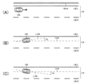
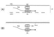
更に、ECU90は、図2の(A)に示したように、周辺情報I_Sに基づいて「自車両100の走行車線(自車線LN)を規定する左側の区画線LM_L及び右側の区画線LM_R」又は「自車両100が走行している道路の端(いわゆる道路端Rend)」を認識することができる。
Furthermore, as shown in FIG. 2A, the
そして、ECU90は、認識した左右区画線LM(即ち、左側の区画線LM_L及び右側の区画線LM_R)又は道路端Rendに基づいてヨー角YAを取得する。ヨー角YAは、図2の(B)及び(C)に示したように、自車線延在方向ラインLLN(自車線LNが延在する方向を表すライン)と自車中央前後ラインL100(自車両100の幅方向中央を自車両100の前後方向に延びるライン)との間の角度である。
The
更に、ECU90は、認識した左右区画線LMに基づいて自車線LNの範囲を特定することができる。
Furthermore, the
加えて、ECU90は、周辺情報I_Sに基づいて自車両100の周辺の他車両を検知することができる。
In addition, the
<車両衝突回避支援装置の作動の概要>
次に、車両衝突回避支援装置10の作動の概要について説明する。車両衝突回避支援装置10は、自車両100の走行中、自車両100の進行方向前方に物体が存在するか否かを周辺情報I_S(特に、自車両100の前方の情報)に基づいて判定している。より具体的には、車両衝突回避支援装置10は、自車両100の走行中、周辺情報I_Sに基づいて自車走行領域A100に物体200が存在するか否かを判定している。自車走行領域A100は、図3に示したように、自車両100の走行ルートR100を中心として自車両100の幅に等しい幅を有する領域である。自車両100の走行ルートR100は、自車両100がその時点の操舵角SAを維持したまま走行したときに自車両100が走行するルートである。尚、本例において、物体は、車両、人、自転車及びガードレール等である。
<Outline of operation of vehicle collision avoidance support device>
Next, an outline of the operation of the vehicle collision
車両衝突回避支援装置10は、自車両100の進行方向前方に物体200が存在しないとき、及び、自車両100の進行方向前方に物体200が存在するがその物体に自車両100が衝突する可能性が低い場合、通常走行制御を実行している。この通常走行制御は、要求駆動力PDreqがゼロよりも大きい場合、その要求駆動力PDreqが駆動装置21から出力されるように駆動装置21の作動を制御し、要求制動力PBreqがゼロよりも大きい場合、その要求制動力PBreqが制動装置22から出力されるように制動装置22の作動を制御し、補助操舵トルクTQasがゼロよりも大きい場合、その補助操舵トルクTQasが操舵装置23から出力されるように操舵装置23の作動を制御する。
The vehicle collision
更に、車両衝突回避支援装置10は、自車両100の走行中、周辺情報I_Sに基づいて自車両100の右隣及び左隣の並走車走行領域A201及び対向車走行領域A202を取得している。並走車走行領域A201は、自車両100の右隣又は左隣が並走車線である場合において、並走車が走行するときにその並走車が占めるであろうと予測される走行領域である。対向車走行領域A202は、自車両100の右隣又は左隣が対向車線である場合において、対向車が走行するときにその対向車が占めるであろうと予測される走行領域である。
Furthermore, while the
<並走車走行領域の取得>
車両衝突回避支援装置10は、以下のようにして並走車走行領域A201を取得する。
<Acquisition of parallel vehicle driving area>
The vehicle collision
自車両100の右隣が並走車線である場合において、並走車201が図4の(A)乃至(D)に示したように走行したと仮定する。即ち、第1時刻t1において図4の(A)に示した位置にいた並走車201が第1時刻t1から第2時刻t2までの間に図4の(B)に示した位置まで走行し、その後、第3時刻t3までの間に図4の(C)に示した位置まで走行し、その後、第4時刻t4までの間に図4の(D)に示した位置まで走行したと仮定する。
When the lane to the right of the
この場合、周辺情報I_Sから推測される並走車201の位置(並走車位置P1)は、図5の(A)乃至(D)に示したように移動する。即ち、第1時刻t1における並走車位置P11は、図5の(A)に示した位置にあり、第2時刻t2における並走車位置P12は、図5の(B)に示した位置にあり、第3時刻t3における並走車位置P13は、図5の(C)に示した位置にあり、第4時刻t4における並走車位置P14は、図5の(D)に示した位置にある。 In this case, the position of the parallel running vehicle 201 (parallel running vehicle position P1) estimated from the surrounding information I_S moves as shown in (A) to (D) of FIG. 5. That is, the parallel running vehicle position P11 at the first time t1 is at the position shown in (A) of FIG. 5, the parallel running vehicle position P12 at the second time t2 is at the position shown in (B) of FIG. 5, the parallel running vehicle position P13 at the third time t3 is at the position shown in (C) of FIG. 5, and the parallel running vehicle position P14 at the fourth time t4 is at the position shown in (D) of FIG. 5.
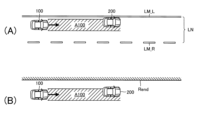
従って、第1時刻t1乃至第4時刻t4それぞれにおける並走車位置P11乃至並走車位置P14は、図6の(A)に示したように移動する。尚、図6の(A)は、第4時刻t4における自車両100及び並走車201の様子を示している。
Therefore, the parallel vehicle positions P11 to P14 at the first time t1 to the fourth time t4, respectively, move as shown in FIG. 6A. Note that FIG. 6A shows the state of the
従って、第1時刻t1乃至第4時刻t4それぞれにおける並走車位置P11乃至P14が分かれば、これら並走車位置P11乃至P14から並走車201が実際に走行した軌跡(並走車走行軌跡R201)を取得することができる。 Therefore, if the parallel vehicle positions P11 to P14 at the first time t1 to the fourth time t4, respectively, are known, the actual path traveled by the parallel vehicle 201 (parallel vehicle travel path R201) can be obtained from these parallel vehicle positions P11 to P14.
一方、車両衝突回避支援装置10は、周辺情報I_Sに基づいて並走車201を検知した場合、その並走車201の自車両100に対する位置(相対位置)を取得することができるが、この位置は、自車両100が移動すれば、それに伴って移動してしまうので、先に説明したような並走車位置P1(並走車201の走行路面(並走車201が実際に走行している路面)上での位置)とは異なってしまう。
On the other hand, when the vehicle collision
そこで、車両衝突回避支援装置10は、周辺情報I_Sに基づいて並走車201を検知した場合、複数の異なる時刻における当該並走車201の自車両100に対する相対位置(並走車相対位置P1_R)を記憶しておく。そして、車両衝突回避支援装置10は、それら並走車相対位置P1_Rをそれぞれ記憶してから自車両100が走行した距離(自車両走行距離)に基づいてそれら並走車相対位置P1_Rをそれぞれ記憶したときの当該並走車201の走行路面上での位置に変換する。より具体的には、車両衝突回避支援装置10は、各並走車相対位置P1_Rを記憶してから自車両100が走行した距離だけ各並走車相対位置P1_Rを自車両100に対して後方に移動させることにより各並走車相対位置P1_Rをそれらを記憶した時点の当該並走車201の走行路面上での位置に変換する。
When the vehicle collision
これら変換された位置は、先に説明した並走車位置P1に相当する。そして、図6の(B)に示したように、車両衝突回避支援装置10は、それら変換した位置から並走車201の走行軌跡(並走車走行軌跡R201)を取得し、その並走車走行軌跡R201に基づいて並走車走行履歴領域A201_Hを取得する。より具体的には、車両衝突回避支援装置10は、並走車走行軌跡R201を中心として並走車201の幅に等しい幅を有する領域を並走車走行履歴領域A201_Hとして取得する。並走車走行履歴領域A201_Hは、図6に示した例においては、並走車201が第1時刻t1から第4時刻t4まで実際に走行したときにその並走車201が占める走行領域である。
These converted positions correspond to the parallel running vehicle position P1 described above. Then, as shown in FIG. 6B, the vehicle collision
更に、車両衝突回避支援装置10は、取得した並走車走行履歴領域A201_Hに基づいて図6の(C)に示したように並走車201が走行するであろうと予測される領域を並走車走行領域A201として取得する。本例においては、車両衝突回避支援装置10は、並走車走行履歴領域A201_Hを自車両100の進行方向前後に延長した領域を並走車走行領域A201として取得する。
Furthermore, the vehicle collision
<対向車走行領域の取得>
又、車両衝突回避支援装置10は、以下のようにして対向車走行領域A202を取得する。
<Acquisition of oncoming vehicle driving area>
In addition, the vehicle collision
自車両100の右隣が対向車線である場合において、対向車202が図7の(A)乃至(D)に示したように走行したと仮定する。即ち、第1時刻t1において図7の(A)に示した位置にいた対向車202が第1時刻t1から第2時刻t2までの間に図7の(B)に示した位置まで走行し、その後、第3時刻t3までの間に図7の(C)に示した位置まで走行し、その後、第4時刻t4までの間に図7の(D)に示した位置まで走行したと仮定する。
When the oncoming lane is to the right of the
この場合、周辺情報I_Sから推測される対向車202の位置(対向車位置P2)は、図8の(A)乃至(D)に示したように移動する。即ち、第1時刻t1における対向車位置P21は、図8の(A)に示した位置にあり、第2時刻t2における対向車位置P22は、図8の(B)に示した位置にあり、第3時刻t3における対向車位置P23は、図8の(C)に示した位置にあり、第4時刻t4における対向車位置P24は、図8の(D)に示した位置にある。 In this case, the position of the oncoming vehicle 202 (oncoming vehicle position P2) estimated from the surrounding information I_S moves as shown in (A) to (D) of FIG. 8. That is, the oncoming vehicle position P21 at the first time t1 is at the position shown in (A) of FIG. 8, the oncoming vehicle position P22 at the second time t2 is at the position shown in (B) of FIG. 8, the oncoming vehicle position P23 at the third time t3 is at the position shown in (C) of FIG. 8, and the oncoming vehicle position P24 at the fourth time t4 is at the position shown in (D) of FIG. 8.
従って、第1時刻t1乃至第4時刻t4それぞれにおける対向車位置P21乃至対向車位置P24は、図9の(A)に示したように移動する。尚、図9の(A)は、第4時刻t4における自車両100及び対向車202の様子を示している。
Therefore, the oncoming vehicle positions P21 to P24 at the first time t1 to the fourth time t4, respectively, move as shown in FIG. 9A. Note that FIG. 9A shows the state of the
従って、第1時刻t1乃至第4時刻t4それぞれにおける対向車位置P21乃至P24が分かれば、これら対向車位置P21乃至P24から対向車202が実際に走行した軌跡(対向車走行軌跡R202)を取得することができる。 Therefore, if the oncoming vehicle positions P21 to P24 at the first time t1 to the fourth time t4, respectively, are known, the actual path traveled by the oncoming vehicle 202 (oncoming vehicle travel path R202) can be obtained from these oncoming vehicle positions P21 to P24.
一方、車両衝突回避支援装置10は、周辺情報I_Sに基づいて対向車202を検知した場合、その対向車202の自車両100に対する位置(相対位置)を取得することができるが、この位置は、自車両100が移動すれば、それに伴って移動してしまうので、先に説明したような対向車位置P2(対向車202の走行路面(対向車202が実際に走行している路面)上での位置)とは異なってしまう。
On the other hand, when the vehicle collision
そこで、車両衝突回避支援装置10は、周辺情報I_Sに基づいて対向車202を検知した場合、複数の異なる時刻における当該対向車202の自車両100に対する相対位置(対向車相対位置P2_R)を記憶しておく。そして、車両衝突回避支援装置10は、それら対向車相対位置P2_Rをそれぞれ記憶してから自車両100が走行した距離(自車両走行距離)に基づいてそれら対向車相対位置P2_Rをそれぞれ記憶したときの当該対向車202の走行路面上での位置に変換する。より具体的には、車両衝突回避支援装置10は、各対向車相対位置P2_Rを記憶してから自車両100が走行した距離だけ各対向車相対位置P2_Rを自車両100に対して後方に移動させることにより各対向車相対位置P2_Rをそれらを記憶した時点の当該対向車202の走行路面上での位置に変換する。
When the vehicle collision
これら変換した位置は、先に説明した対向車位置P2に相当する。そして、図9の(B)に示したように、車両衝突回避支援装置10は、それら変換した位置から対向車202の走行軌跡(対向車走行軌跡R202)を取得し、その対向車走行軌跡R202に基づいて対向車走行履歴領域A202_Hを取得する。より具体的には、車両衝突回避支援装置10は、対向車走行軌跡R202を中心として対向車202の幅に等しい幅を有する領域を対向車走行履歴領域A202_Hとして取得する。対向車走行履歴領域A202_Hは、図9に示した例においては、対向車202が第1時刻t1から第4時刻t4まで実際に走行したときにその対向車202が占める走行領域である。
These converted positions correspond to the oncoming vehicle position P2 described above. Then, as shown in FIG. 9B, the vehicle collision
更に、車両衝突回避支援装置10は、取得した対向車走行履歴領域A202_Hに基づいて図9の(C)に示したように対向車202が走行するであろうと予測される領域を対向車走行領域A202として取得する。本例においては、車両衝突回避支援装置10は、対向車走行履歴領域A202_Hを自車両100の進行方向前後に延長した領域を対向車走行領域A202として取得する。
Furthermore, the vehicle collision
車両衝突回避支援装置10は、図10の(A)及び図10の(B)に示したように、自車走行領域A100内に物体200が存在する場合、周辺情報I_Sに基づいて物体距離D200、相対速度dV及び予測到達時間TTCを所定演算周期で取得する。物体距離D200は、自車走行領域A100内に存在する物体200と自車両100との間の距離であり、相対速度dVは、自車走行領域A100内に存在する物体200に対する自車両100の速度である。又、予測到達時間TTCは、自車両100が物体200に到達するまでに要すると推定される時間である。車両衝突回避支援装置10は、物体距離D200を相対速度dVで除算することにより予測到達時間TTC(=D200/dV)を取得する。車両衝突回避支援装置10は、自車走行領域A100内に物体200が存在すると判定している間、物体距離D200、相対速度dV及び予測到達時間TTCの取得を所定演算周期CYCで行う。
As shown in FIG. 10A and FIG. 10B, when an
尚、図10の(A)は、左右区画線LMを周辺情報I_Sから認識できている状況において自車走行領域A100内に物体200が存在する場面を示しており、図10の(B)は、左右区画線LMを周辺情報I_Sから認識できていない状況において自車走行領域A100内に物体200が存在する場面を示している。
Incidentally, FIG. 10(A) shows a situation in which an
車両衝突回避支援装置10は、物体距離D200が所定距離(所定物体距離D200th)まで短くなったとき、回避経路設定条件が成立したと判定する。即ち、車両衝突回避支援装置10は、物体200に自車両100が衝突する可能性を表す指標値として物体距離D200を取得し、その指標値が所定指標値以上になったとき、回避経路設定条件が成立したと判定する。従って、この場合、物体200に自車両100が衝突する可能性を表す指標値は、物体距離D200が短くなるほどその値が大きくなる。
The vehicle collision
車両衝突回避支援装置10は、回避経路設定条件が成立したと判定すると、物体200を避けて自車両100を走行させる経路(目標回避経路Rtgt)を設定する処理を開始する。
When the vehicle collision
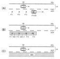
本例においては、車両衝突回避支援装置10は、左右区画線LMを周辺情報I_Sから認識できている場合、図11に示したように、自車両100が物体200を避けて通過でき且つ自車両100が自車線LN内で走行するように(即ち、自車両100が自車線LNから外に出ないように)自車両100を走行させることができる経路を目標回避経路Rtgtとして設定する。図11に示した目標回避経路Rtgtは、物体200の右横を通るように自車両100を走行させる経路であるが、物体200の左横に自車両100が走行可能なスペースが存在する場合、物体200の左横を通る目標回避経路Rtgtが設定されることもある。
In this example, when the vehicle collision
尚、車両衝突回避支援装置10は、物体200の右横に自車両100を走行させるスペースが存在する場合において、少なくとも自車線LNを規定する右側の区画線LM_Rを認識できているときには、自車両100が物体200の右横を通り且つ自車両100が右側の区画線LM_Rの左側で走行するように(即ち、自車両100が右側の区画線LM_Rの右側に出ないように)自車両100を走行させることができる経路を目標回避経路Rtgtとして設定するように構成されてもよい。同様に、車両衝突回避支援装置10は、物体200の左横に自車両100を走行させるスペースが存在する場合において、少なくとも自車線LNを規定する左側の区画線LM_Lを認識できているときには、自車両100が物体200の左横を通り且つ自車両100が左側の区画線LM_Lの右側で走行するように(即ち、自車両100が左側の区画線LM_Lの左側に出ないように)自車両100を走行させることができる経路を目標回避経路Rtgtとして設定するように構成されてもよい。
Furthermore, when there is space to the right of the
一方、車両衝突回避支援装置10は、左右区画線LMを認識できておらず、従って、自車線LNの範囲を特定することができない場合、図12の(A)に示したように、自車両100が自車線LN内で走行するか否かを問わず、自車両100が物体200を避けて通過できる経路を目標回避経路Rtgtとして設定する。図12の(A)に示した目標回避経路Rtgtは、物体200の右横を通るように自車両100を走行させる経路であるが、物体200の左横に自車両100が走行可能なスペースが存在する場合、物体200の左横を通る目標回避経路Rtgtが設定されることもある。
On the other hand, when the vehicle collision
尚、車両衝突回避支援装置10は、左右区画線LMを認識できていない場合、図12の(B)に示したように、目標回避経路Rtgtを設定するように構成されてもよい。図12の(B)に示した目標回避経路Rtgtは、物体200の右横を通るように自車両100を走行させた後、物体200の前方に自車両100を戻す経路である。
The vehicle collision
又、目標回避経路Rtgtに沿って走行するように自車両100を強制的に操舵することにより自車両100と物体200との衝突を回避するためには、目標回避経路Rtgtの設定に際し、物体200に対する自車両100の相対速度dVに応じた目標回避経路Rtgtを設定することが好ましい。そこで、車両衝突回避支援装置10は、物体200に対する自車両100の相対速度dVを考慮して目標回避経路Rtgtを設定するように構成されてもよい。
In addition, in order to avoid a collision between the
又、車両衝突回避支援装置10は、物体200を避けて自車両100が安全に走行することができるスペースが物体200の横に存在せず、従って、目標回避経路Rtgtを設定できない場合、回避操舵の実施を禁止する。従って、この場合、後述する回避操舵開始条件が成立しても、回避操舵は実施されない。
Furthermore, if there is no space beside the
又、車両衝突回避支援装置10は、回避経路設定条件が成立する前又は成立したときに自車両100が物体200に衝突する可能性があることを自車両100の運転者に知らせるための警報を行い、それにもかかわらず、運転者が自車両100と物体200との衝突を避けるための操作(アクセルペダル31に対する操作、ブレーキペダル32に対する操作及びハンドル33に対する操作)を行わないまま、回避操舵開始条件が成立したときに回避操舵を開始するように構成されてもよい。
The vehicle collision
車両衝突回避支援装置10は、左右区画線LMを認識できていない場合において、目標回避経路Rtgtを設定すると、図12の(C)に示したように、設定した目標回避経路Rtgtを中心として自車両100の幅に等しい幅を有する領域を回避走行領域Atgtとして推定により取得する。回避走行領域Atgtは、自車両100が目標回避経路Rtgtに沿って走行したと仮定したときに自車両100が占める走行領域に相当する。
When the vehicle collision
車両衝突回避支援装置10は、回避走行領域Atgtを取得すると、その回避走行領域Atgtが対向車走行領域A202と重なっているか否かを判定する。別の言い方をすると、車両衝突回避支援装置10は、回避走行領域Atgtが対向車走行領域A202上に存在するか否かを判定する。
When the vehicle collision
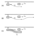
車両衝突回避支援装置10は、図13の(A)に示したように、回避走行領域Atgtが対向車走行領域A202と重なっていると判定した場合、回避操舵の実施を禁止する。この場合、後述する回避操舵開始条件が成立しても、回避操舵は実施されない。
When the vehicle collision
一方、車両衝突回避支援装置10は、図13の(B)に示したように、回避走行領域Atgtが対向車走行領域A202と重なっていないと判定した場合、回避走行領域Atgtが並走車走行領域A201と重なっているか否かを判定する。別の言い方をすると、車両衝突回避支援装置10は、回避走行領域Atgtが並走車走行領域A201上に存在するか否かを判定する。
On the other hand, when the vehicle collision
又、車両衝突回避支援装置10は、回避走行領域Atgtを取得したときに対向車走行領域A202を取得していない場合も、回避走行領域Atgtが並走車走行領域A201と重なっているか否かを判定する。
In addition, even if the vehicle collision
車両衝突回避支援装置10は、図13の(C)に示したように、回避走行領域Atgtが並走車走行領域A201と重なっていると判定した場合、回避操舵の実施を許可する。この場合、後述する回避操舵開始条件が成立した場合、回避操舵が開始される。
When the vehicle collision
一方、車両衝突回避支援装置10は、図13の(D)に示したように、回避走行領域Atgtが並走車走行領域A201と重なっていないと判定した場合、回避操舵の実施を禁止する。この場合、後述する回避操舵開始条件が成立しても、回避操舵は実施されない。
On the other hand, as shown in FIG. 13D, when the vehicle collision
又、車両衝突回避支援装置10は、回避走行領域Atgtを取得したときに対向車走行領域A202も並走車走行領域A201も取得していない場合、回避操舵の実施を禁止する。この場合、後述する回避操舵開始条件が成立しても、回避操舵は実施されない。
In addition, when the vehicle collision
尚、車両衝突回避支援装置10は、回避走行領域Atgtが対向車走行領域A202とも並走車走行領域A201とも重なっていないと判定した場合、回避操舵の実施を許可するように構成されてもよい。
The vehicle collision
予測到達時間TTCは、相対速度dVが一定である場合、自車両100が物体200に近づくほど短くなる。自車両100が物体200に近づき、予測到達時間TTCが所定時間(所定予測到達時間TTCth)まで短くなったとき、車両衝突回避支援装置10は、回避操舵開始条件が成立したと判定する。即ち、車両衝突回避支援装置10は、物体200に自車両100が衝突する可能性を表す指標値として予測到達時間TTCを取得し、その指標値が所定指標値以上になったとき、回避操舵開始条件が成立したと判定する。従って、この場合、物体200に自車両100が衝突する可能性を表す指標値は、予測到達時間TTCが短くなるほどその値が大きくなる。
When the relative speed dV is constant, the predicted arrival time TTC becomes shorter as the
車両衝突回避支援装置10は、左右区画線LMを認識できており且つ目標回避経路Rtgtを設定できているときに回避操舵開始条件が成立した場合、回避操舵を開始する。このとき、車両衝突回避支援装置10は、目標回避経路Rtgtに沿って自車両100が走行するように補助操舵トルクTQasを制御する自車両100の操舵(回避操舵)を実行する。これにより、図14の(A)に示したように、自車両100が目標回避経路Rtgtに沿って走行するように自車両100が操舵され、図14の(B)に示したように、物体200との衝突を回避することができる。
The vehicle collision
尚、車両衝突回避支援装置10は、回避操舵とともに自車両100に与える駆動力を低下させ或いは一定値以下に制限することにより又は自車両100に制動力を与えることにより減速させてもよい。
The vehicle collision
又、車両衝突回避支援装置10は、左右区画線LMを認識できていないが回避操舵の実施が許可されており且つ目標回避経路Rtgtを設定できているときに回避操舵開始条件が成立した場合も、回避操舵を開始する。このときも、車両衝突回避支援装置10は、目標回避経路Rtgtに沿って自車両100が走行するように補助操舵トルクTQasを制御する自車両100の操舵(回避操舵)を実行する。これにより、図14の(C)に示したように、自車両100が目標回避経路Rtgtに沿って走行するように自車両100が操舵され、図14の(D)に示したように、物体200との衝突を回避することができる。
The vehicle collision
尚、回避操舵の実施を禁止する条件(回避操舵禁止条件)として、以下に述べる条件C1乃至条件C21を適宜採用することもできる。 In addition, conditions C1 to C21 described below can be appropriately adopted as conditions for prohibiting the implementation of avoidance steering (avoidance steering prohibition conditions).
条件C1は、回避操舵を実現するための機器(例えば、操舵装置23)に異常がある等の理由から、回避操舵を実現することができないとの条件である。 Condition C1 is a condition in which avoidance steering cannot be realized due to an abnormality in the device for realizing avoidance steering (e.g., the steering device 23).
条件C2は、車両衝突回避支援装置10が自動ブレーキ制御(PCS)を実行可能に構成されている場合において、その自動ブレーキ制御を実現するための機器(例えば、制動装置22)に異常がある等の理由から、その自動ブレーキ制御を実現することができないとの条件である。自動ブレーキ制御とは、自車両100がその前方に存在する物体に衝突する可能性が高まったときに自車両100を強制的に制動して自車両100が物体に衝突する前に停止させる制御である。
Condition C2 is a condition that, when the vehicle collision
条件C3は、車両衝突回避支援装置10が横滑り防止制御(VSC)を実行可能に構成されている場合において、その横滑り防止制御を実現するための機器(例えば、制動装置22)に異常がある等の理由から、その横滑り防止制御を実現することができないとの条件である。横滑り防止制御とは、例えば、自車両100の操舵に起因して自車両100の走行挙動が不安定になったときに自車両100の駆動輪に与える駆動力PDを調整し或いは自車両100の車輪それぞれに与える制動力PBを個別に調整することにより自車両100の走行挙動を安定させる制御である。
Condition C3 is a condition that, when the vehicle collision
条件C4は、車両衝突回避支援装置10が自動ブレーキ制御(PCS)を実行可能に構成されている場合において、その自動ブレーキ制御により自車両100が物体200に衝突する前に自車両100を停止させることができるとの条件である。
Condition C4 is a condition that, when the vehicle collision
条件C5は、車両衝突回避支援装置10が自動ブレーキ制御(PCS)を実行可能に構成されており且つその自動ブレーキ制御が先に実行された場合において、その自動ブレーキ制御の終了時点から経過した時間が所定時間以内であるとの条件である。
Condition C5 is a condition that, if the vehicle collision
条件C6は、操舵回避制御が先に実行された場合において、その操舵回避制御の終了時点から経過した時間が所定時間以内であるとの条件である。 Condition C6 is a condition that, if steering avoidance control is executed first, the time that has elapsed since the steering avoidance control ended is within a predetermined time.
条件C7は、自車両100のウインカーを作動(点滅)させているとの条件である。
Condition C7 is a condition that the turn signal of the
条件C8は、物体200が先行車であり且つ目標回避経路Rtgtがその先行車の左側を通過するルートである場合において、その先行車の左側のウインカーが作動(点滅)しているとの条件である。車両衝突回避支援装置10は、周辺情報I_Sに基づいて先行車の左側のウインカーが作動(点滅)しているか否かを判別することができる。尚、先行車は、自車両100の進行方向と同一方向に自車両100の前方で自車線LNを走行している車両である。
Condition C8 is a condition that when the
条件C9は、物体200が先行車であり且つ目標回避経路Rtgtがその先行車の右側を通過するルートである場合において、その先行車の右側のウインカーが作動(点滅)しているとの条件である。車両衝突回避支援装置10は、周辺情報I_Sに基づいて先行車の右側のウインカーが作動(点滅)しているか否かを判別することができる。
Condition C9 is a condition that, when the
条件C10は、アクセルペダル操作量APが所定アクセルペダル操作量APth以上であるとの条件である。 Condition C10 is a condition that the accelerator pedal operation amount AP is equal to or greater than a predetermined accelerator pedal operation amount APth.
条件C11は、ブレーキペダル操作量BPが所定ブレーキペダル操作量BPth以上であるとの条件である。 Condition C11 is a condition that the brake pedal operation amount BP is equal to or greater than a predetermined brake pedal operation amount BPth.
条件C12は、自車両100の車速Vが所定範囲Rv内の車速ではないとの条件である。
Condition C12 is a condition that the vehicle speed V of the
条件C13は、自車両100に対する物体200の相対速度dVが所定範囲Rdv内の速度ではないとの条件である。
Condition C13 is a condition that the relative speed dV of the
条件C14は、横加速度Gyが所定横加速度Gy_th以上であるとの条件である。 Condition C14 is a condition that the lateral acceleration Gy is equal to or greater than a predetermined lateral acceleration Gy_th.
条件C15は、縦加速度Gxが正の値であり且つその絶対値が所定値Gx_th以上であるとの条件である。 Condition C15 is that the vertical acceleration Gx is a positive value and its absolute value is equal to or greater than a predetermined value Gx_th.
条件C16は、縦加速度Gxが負の値であり且つその絶対値が所定値Gx_th以上であるとの条件である。 Condition C16 is that the vertical acceleration Gx is a negative value and its absolute value is equal to or greater than a predetermined value Gx_th.
条件C17は、自車両100がカーブ路を走行中であるとの条件である。車両衝突回避支援装置10は、周辺情報I_Sに基づいて自車両100がカーブ路を走行中であるか否かを判別することができる。
Condition C17 is a condition that the
条件C18は、目標回避経路Rtgtが物体200の前後方向中央ラインと交差するとの条件である。車両衝突回避支援装置10は、周辺情報I_Sに基づいて目標回避経路Rtgtが物体200の前後方向中央ラインと交差するか否かを判別することができる。
Condition C18 is a condition that the target avoidance path Rtgt intersects with the longitudinal center line of the
条件C19は、物体200が目標回避経路Rtgtを横切るように移動しているとの条件である。車両衝突回避支援装置10は、周辺情報I_Sに基づいて物体200が目標回避経路Rtgtを横切るように移動しているか否かを判別することができる。
Condition C19 is a condition that the
条件C20は、目標回避経路Rtgtを設定することはできたが、その目標回避経路Rtgtがそれに沿って自車両100を走行させることができないと予測されるルートであるとの条件である。
Condition C20 is a condition that the target avoidance route Rtgt can be set, but that the target avoidance route Rtgt is a route along which it is predicted that the
<操舵回避制御の終了>
車両衝突回避支援装置10は、回避操舵を終了する条件(回避操舵終了条件)が成立した場合、回避操舵を終了する。例えば、左右区画線LMが認識できている場合、回避操舵の開始後、図15の(A)に示したように、自車両100が物体200の横を通過しているときに回避操舵を終了させても、自車両100が物体200に衝突することはない。同様に、左右区画線LMが認識できていない場合も、回避操舵の開始後、図15の(B)に示したように、自車両100が物体200の横を通過しているときに回避操舵を終了させても、自車両100が物体200に衝突することはない。そこで、回避操舵終了条件として、例えば、回避操舵の開始後、自車両100が物体200の横を通過しているとの条件が設定される。
<End of steering avoidance control>
The vehicle collision
尚、車両衝突回避支援装置10は、周辺情報I_Sに基づいて自車両100が物体200の横を通過していると判定することができる。又、自車両100が物体200の横を通過しているとき、ヨー角YAの絶対値が小さくなる。そこで、車両衝突回避支援装置10は、回避操舵の開始後、ヨー角YAの絶対値が所定ヨー角YAth以下となったときに自車両100が物体200の横を通過していると判定するように構成されてもよい。又、自車両100が物体200の横を通過しているとき、自車両100のヨーレートの絶対値が小さくなる。そこで、車両衝突回避支援装置10は、自車両100のヨーレートの絶対値が所定ヨーレート以下となったときに自車両100が物体200の横を通過していると判定するように構成されてもよい。
The vehicle collision
又、車両衝突回避支援装置10は、自車両100を停止させるように自車両100を制動しつつ、回避操舵を実施するように構成されている場合、自車両100が停止したときに回避操舵終了条件が成立したと判定するように構成されてもよい。
In addition, when the vehicle collision
又、車両衝突回避支援装置10は、操舵回避制御の実行中にドライバー入力トルクTQdrが比較的大きい所定トルクTQth以上となった場合、回避操舵を中止するように構成されていてもよい。
The vehicle collision
<効果>
自車線LNの隣の車線(隣接車線)が並走車線である場合、隣接車線が対向車線である場合に比べ、自車両100が物体200との衝突を回避するためにその隣接車線に進入しても、比較的安全である。従って、回避走行領域Atgtが並走車走行領域A201に重なっている場合、自車両100が物体200との衝突を回避するために進入しようとしている隣接車線が並走車線であるので、自車両100がその隣接車線に進入しても、比較的安全である。車両衝突回避支援装置10によれば、回避走行領域Atgtが対向車走行領域A202に重なっている場合には、回避操舵は実施されないが、回避走行領域Atgtが並走車走行領域A201に重なっている場合には、回避操舵は実施される。従って、自車両100と物体200との衝突を回避操舵により回避するときに自車両100を自車線LN内で走行させることができない場合でも、回避操舵が実施される。このため、自車線LNを特定できない場合でも、自車両100と物体200との衝突を安全に回避することができる。
<Effects>
When a lane (adjacent lane) next to the own lane LN is a parallel lane, it is relatively safe for the
<車両衝突回避支援装置の具体的な作動>
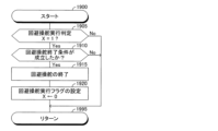
次に、車両衝突回避支援装置10の具体的な作動について説明する。車両衝突回避支援装置10のECU90のCPUは、図16に示したルーチンを所定時間の経過毎に実行するようになっている。従って、所定のタイミングになると、CPUは、図16のステップ1600から処理を開始し、その処理をステップ1605に進め、回避操舵実行フラグXの値が「0」であるか否かを判定する。回避操舵実行フラグXの値は、回避操舵が開始されたときに「1」に設定され、回避操舵が終了されたときに「0」に設定される。
<Specific Operation of Vehicle Collision Avoidance Assistance Device>
Next, a specific operation of the vehicle collision
CPUは、ステップ1605にて「Yes」と判定した場合、処理をステップ1610に進め、並走車走行領域A201及び対向車走行領域A202を取得する。次いで、CPUは、処理をステップ1615に進め、回避経路設定条件が成立したか否かを判定する。
If the CPU judges "Yes" in
CPUは、ステップ1615にて「Yes」と判定した場合、処理をステップ1620に進め、左右区画線LMを認識できているか否かを判定する。
If the CPU determines "Yes" in
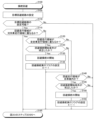
CPUは、ステップ1620にて「Yes」と判定した場合、処理をステップ1625に進め、図17に示したルーチンを実行する。従って、CPUは、処理をステップ1625に進めると、図17のステップ1700から処理を開始し、その処理をステップ1705に進め、目標回避経路Rtgtを設定する。次いで、CPUは、処理をステップ1710に進め、目標回避経路Rtgtを設定できたか否かを判定する。
If the CPU judges "Yes" at
CPUは、ステップ1710にて「Yes」と判定した場合、処理をステップ1715に進め、回避操舵開始条件が成立したか否かを判定する。
If the CPU judges "Yes" in
CPUは、ステップ1715にて「Yes」と判定した場合、処理をステップ1720に進め、回避操舵を開始する。次いで、CPUは、処理をステップ1725に進め、回避操舵実行フラグXの値を「1」に設定する。次いで、CPUは、ステップ1795を経由して図16のステップ1695に処理を進め、本ルーチンを一旦終了する。
If the CPU determines "Yes" in
一方、CPUは、ステップ1710又はステップ1715にて「No」と判定した場合、ステップ1795を経由して図16のステップ1695に処理を進め、本ルーチンを一旦終了する。この場合、回避操舵は実施されていない。
On the other hand, if the CPU judges "No" at
図16のステップ1620にて「No」と判定した場合、処理をステップ1630に進め、図18に示したルーチンを実行する。従って、CPUは、処理をステップ1630に進めると、図18のステップ1800から処理を開始し、その処理をステップ1805に進め、目標回避経路Rtgtを設定する。次いで、CPUは、処理をステップ1810に進め、目標回避経路Rtgtを設定できたか否かを判定する。
If the determination at
CPUは、ステップ1810にて「Yes」と判定した場合、処理をステップ1815に進め、回避走行領域Atgtが対向車走行領域A202と重なっているか否かを判定する。
If the CPU judges "Yes" in
CPUは、ステップ1815にて「Yes」と判定した場合、ステップ1895を経由して図16のステップ1695に処理を進め、本ルーチンを一旦終了する。
If the CPU judges "Yes" in
一方、CPUは、ステップ1815にて「No」と判定した場合、処理をステップ1820に進め、回避走行領域Atgtが並走車走行領域A201と重なっているか否かを判定する。
On the other hand, if the CPU determines "No" in
CPUは、ステップ1820にて「Yes」と判定した場合、処理をステップ1825に進め、回避操舵開始条件が成立したか否かを判定する。
If the CPU judges "Yes" in
CPUは、ステップ1825にて「Yes」と判定した場合、処理をステップ1830に進め、回避操舵を開始する。次いで、CPUは、処理をステップ1835にて回避操舵実行フラグXの値を「1」に設定する。次いで、CPUは、ステップ1895を経由して図16のステップ1695に処理を進め、本ルーチンを一旦終了する。
If the CPU determines "Yes" in
一方、CPUは、ステップ1820又はステップ1825にて「No」と判定した場合、ステップ1895を経由して図16のステップ1695に処理を進め、本ルーチンを一旦終了する。
On the other hand, if the CPU judges "No" at
又、CPUは、ステップ1810にて「No」と判定した場合も、ステップ1895を経由して図16のステップ1695に処理を進め、本ルーチンを一旦終了する。
Also, if the CPU judges "No" in
更に、CPUは、図19に示したルーチンを所定演算時間の経過毎に実行するようになっている。従って、所定のタイミングになると、CPUは、図19のステップ1900から処理を開始し、その処理をステップ1905に進め、回避操舵実行フラグXの値が「1」であるか否かを判定する。
Furthermore, the CPU executes the routine shown in FIG. 19 every time a predetermined calculation time has elapsed. Therefore, at a predetermined timing, the CPU starts processing from
CPUは、ステップ1905にて「Yes」と判定した場合、処理をステップ1910に進め、回避操舵終了条件が成立したか否かを判定する。
If the CPU determines "Yes" in
CPUは、ステップ1910にて「Yes」と判定した場合、処理をステップ1915に進め、回避操舵を終了する。次いで、CPUは、処理をステップ1920に進め、回避操舵実行フラグXの値を「0」に設定する。次いで、CPUは、処理をステップ1995に進め、本ルーチンを一旦終了する。
If the CPU determines "Yes" in
一方、CPUは、ステップ1905又はステップ1910にて「No」と判定した場合、処理をステップ1915に直接進め、本ルーチンを一旦終了する。
On the other hand, if the CPU judges "No" at
以上が車両衝突回避支援装置10の具体的な作動である。
The above is the specific operation of the vehicle collision
尚、本発明は、上記実施形態に限定されることはなく、本発明の範囲内において種々の変形例を採用することができる。 The present invention is not limited to the above embodiment, and various modifications can be made within the scope of the present invention.
<変形例>
例えば、車両衝突回避支援装置10は、回避経路設定条件が成立したときに左右区画線LMを周辺情報I_Sから認識できているか否かを判断せず、目標回避経路Rtgtを設定し、その目標回避経路Rtgtに基づいて取得した回避走行領域Atgtが対向車走行領域A202又は並走車走行領域A201と重なっているか否かに応じて回避操舵を許可したり禁止したりするように構成されてもよい。
<Modification>
For example, the vehicle collision
この本発明の実施形態の変形例に係る車両衝突回避支援装置10は、回避経路設定条件が成立した場合、目標回避経路Rtgtを設定し、その目標回避経路Rtgtに基づいて回避走行領域Atgtを取得し、その回避走行領域Atgtが対向車走行領域A202と重なっているか否かを判定する。
When the avoidance route setting condition is satisfied, the vehicle collision
回避走行領域Atgtが対向車走行領域A202と重なっている場合、車両衝突回避支援装置10は、回避操舵の実施を禁止する。従って、この場合、回避操舵開始条件が成立しても、回避操舵は実施されない。
When the avoidance driving area Atgt overlaps with the oncoming vehicle driving area A202, the vehicle collision
一方、回避走行領域Atgtが対向車走行領域A202と重なっていない場合、車両衝突回避支援装置10は、回避走行領域Atgtが並走車走行領域A201に重なっているか否かを判定する。
On the other hand, if the avoidance driving area Atgt does not overlap with the oncoming vehicle driving area A202, the vehicle collision
回避走行領域Atgtが並走車走行領域A201に重なっている場合、車両衝突回避支援装置10は、回避操舵の実施を許可する。従って、この場合、回避操舵開始条件が成立したときに、回避操舵が実施される。
When the avoidance driving area Atgt overlaps with the parallel vehicle driving area A201, the vehicle collision
一方、回避走行領域Atgtが並走車走行領域A201に重なっていない場合、車両衝突回避支援装置10は、回避走行領域Atgtが自車線LN内にあるか否かを判定する。
On the other hand, if the avoidance driving area Atgt does not overlap with the parallel vehicle driving area A201, the vehicle collision
回避走行領域Atgtが自車線LN内にある場合、車両衝突回避支援装置10は、回避操舵の実施を許可する。従って、この場合、回避操舵開始条件が成立したときに、回避操舵が実施される。
When the avoidance driving area Atgt is within the own lane LN, the vehicle collision
回避走行領域Atgtが自車線LN内にない場合、車両衝突回避支援装置10は、回避操舵の実施を禁止する。従って、この場合、回避操舵開始条件が成立しても、回避操舵は実施されない。
If the avoidance driving area Atgt is not within the own lane LN, the vehicle collision
尚、車両衝突回避支援装置10は、左右区画線LMを認識できておらず、従って、自車線LNの範囲を特定できていない場合、回避操舵の実施を禁止する。
Furthermore, if the vehicle collision
<効果>
本発明の実施形態に係る車両衝突回避支援装置10と同様に、変形例に係る車両衝突回避支援装置10によれば、回避走行領域Atgtが対向車走行領域A202に重なっている場合には、回避操舵は実施されないが、回避走行領域Atgtが並走車走行領域A201に重なっている場合には、回避操舵は実施される。従って、自車両100と物体200との衝突を回避操舵により回避するときに自車両100を自車線LN内で走行させることができない場合でも、自車両100と物体200との衝突を回避するための回避操舵が実施される。このため、自車線LNを特定できない場合でも、自車両100と物体200との衝突を安全に回避することができる。
<Effects>
As with the vehicle collision
次に、本発明の実施形態の変形例に係る車両衝突回避支援装置10の具体的な作動について説明する。この車両衝突回避支援装置10のECU90のCPUは、図20に示したルーチンを所定時間の経過毎に実行するようになっている。従って、所定のタイミングになると、CPUは、図20のステップ2000から処理を開始し、その処理をステップ2005に進め、回避操舵実行フラグXの値が「0」であるか否かを判定する。
Next, the specific operation of the vehicle collision
CPUは、ステップ2005にて「Yes」と判定した場合、処理をステップ2010に進め、並走車走行領域A201又は対向車走行領域A202を取得する。次いで、CPUは、処理をステップ2015に進め、回避経路設定条件が成立したか否かを判定する。
If the CPU judges "Yes" in
CPUは、ステップ2015にて「Yes」と判定した場合、処理をステップ2020に進め、図21に示したルーチンを実行する。従って、CPUは、処理をステップ2020に進めると、図21のステップ2100から処理を開始し、その処理をステップ2105に進め、目標回避経路Rtgtを設定する。次いで、CPUは、処理をステップ2110に進め、目標回避経路Rtgtを設定することができたか否かを判定する。
If the CPU judges "Yes" in
CPUは、ステップ2110にて「Yes」と判定した場合、処理をステップ2115に進め、回避走行領域Atgtが対向車走行領域A202に重なっているか否かを判定する。
If the CPU judges "Yes" in
CPUは、ステップ2115にて「Yes」と判定した場合、ステップ2195を経由してステップ2095に処理を進め、本ルーチンを一旦終了する。この場合、回避操舵は実施されない。
If the CPU judges "Yes" in
一方、CPUは、ステップ2115にて「No」と判定した場合、処理をステップ2120に進め、回避走行領域Atgtが並走車走行領域A201に重なっているか否かを判定する。
On the other hand, if the CPU judges "No" in
CPUは、ステップ2120にて「Yes」と判定した場合、処理をステップ2125に進め、回避操舵開始条件が成立したか否かを判定する。
If the CPU judges "Yes" in
CPUは、ステップ2125にて「Yes」と判定した場合、処理をステップ2130に進め、回避操舵を開始する。次いで、CPUは、処理をステップ2135に進め、回避操舵実行フラグXの値を「1」に設定する。次いで、CPUは、ステップ2195を経由してステップ2095に処理を進め、本ルーチンを一旦終了する。
If the CPU determines "Yes" in
一方、CPUは、ステップ2125にて「No」と判定した場合、ステップ2195を経由してステップ2095に処理を進め、本ルーチンを一旦終了する。
On the other hand, if the CPU judges "No" at
又、CPUは、ステップ2120にて「No」と判定した場合、処理をステップ2140に進め、回避走行領域Atgtが自車線LN内にあるか否かを判定する。
If the CPU determines "No" in
CPUは、ステップ2140にて「Yes」と判定した場合、処理をステップ2145に進め、回避操舵開始条件が成立したか否かを判定する。
If the CPU judges "Yes" in
CPUは、ステップ2145にて「Yes」と判定した場合、処理をステップ2150に進め、回避操舵を開始する。次いで、CPUは、処理をステップ2155に進め、回避操舵実行フラグXの値を「1」に設定する。次いで、CPUは、ステップ2195を経由してステップ2095に処理を進め、本ルーチンを一旦終了する。
If the CPU determines "Yes" in
一方、CPUは、ステップ2110又はステップ2140又はステップ2145にて「No」と判定した場合、ステップ2195を経由してステップ2095に処理を進め、本ルーチンを一旦終了する。
On the other hand, if the CPU judges "No" at
以上が本発明の実施形態の変形例に係る車両衝突回避支援装置10の具体的な作動である。
The above is the specific operation of the vehicle collision
10…車両衝突回避支援装置、21…駆動装置、22…制動装置、23…操舵装置、68…周辺情報取得装置、90…ECU、100…自車両、200…物体、201…並走車、202…対向車、A100…自車走行領域、Atgt…回避走行領域、A201…並走車走行領域、A202…対向車走行領域、LM…左右区画線、LM_L…左側の区画線、LM_R…右側の区画線、Rtgt…目標回避経路 10...vehicle collision avoidance support device, 21...driving device, 22...braking device, 23...steering device, 68...peripheral information acquisition device, 90...ECU, 100...own vehicle, 200...object, 201...parallel vehicle, 202...oncoming vehicle, A100...own vehicle driving area, Atgt...avoidance driving area, A201...parallel vehicle driving area, A202...oncoming vehicle driving area, LM...left and right dividing lines, LM_L...left dividing line, LM_R...right dividing line, Rtgt...target avoidance path
Claims (4)
前記自車両の隣で走行する他車両が並走車であるときには該並走車が走行するときに該並走車が占める走行領域を並走車走行領域として記憶しておき、
前記他車両が対向車であるときには該対向車が走行するときに該対向車が占める走行領域を対向車走行領域として記憶しておき、
前記自車両が前記物体に衝突する可能性がある場合において、前記回避経路設定条件が成立したときに前記自車線を特定することができていないときには、前記自車両と前記物体との衝突を回避可能な回避経路であって前記自車両が前記物体を避けて当該物体の横を通過できる回避経路を第2の目標回避経路として設定し、該第2の目標回避経路に沿って前記自車両が走行したと仮定したときに前記自車両が占める走行領域を回避走行領域として取得し、
前記取得した回避走行領域が前記記憶してある対向車走行領域に重なっている場合には、前記第2の目標回避経路に沿って前記自車両が走行するように前記自車両を強制的に操舵する第2の回避操舵を開始する第2の回避操舵開始条件が成立しても、前記第2の回避操舵を実施せず、
前記取得した回避走行領域が前記記憶してある並走車走行領域に重なっている場合には、前記第2の回避操舵開始条件が成立したときに、前記第2の回避操舵を実施し、
前記取得した回避走行領域が前記対向車走行領域にも前記並走車走行領域にも重なっていない場合、前記第2の回避操舵開始条件が成立しても、前記第2の回避操舵を実施しない、
ように構成されている、
車両衝突回避支援装置。 a vehicle collision avoidance support device configured to perform first evasive steering when a first evasive steering start condition is satisfied, the device being configured to set, as a first target evasive route, an evasive route that can avoid a collision between the host vehicle and the object, the host vehicle being able to pass beside the object while avoiding the object, and the host vehicle being able to travel within the host vehicle's lane, when there is a possibility that the host vehicle will collide with an object present in front of the host vehicle, and to perform first evasive steering when a first evasive steering start condition is satisfied,
When the vehicle traveling next to the host vehicle is a parallel running vehicle, a running area occupied by the parallel running vehicle when the parallel running vehicle is traveling is stored as a parallel running vehicle running area;
When the other vehicle is an oncoming vehicle, a travel area occupied by the oncoming vehicle when the oncoming vehicle travels is stored as an oncoming vehicle travel area;
When there is a possibility that the host vehicle will collide with the object, if the host vehicle lane cannot be identified when the avoidance route setting condition is satisfied, an avoidance route that can avoid a collision between the host vehicle and the object and that allows the host vehicle to pass beside the object while avoiding the object is set as a second target avoidance route, and a driving area that the host vehicle would occupy when it is assumed that the host vehicle travels along the second target avoidance route is acquired as an avoidance driving area;
When the acquired avoidance driving area overlaps with the stored oncoming vehicle driving area, even if a second avoidance steering start condition is satisfied for starting a second avoidance steering for forcibly steering the host vehicle so that the host vehicle travels along the second target avoidance path , the second avoidance steering is not performed;
When the acquired avoidance driving area overlaps with the stored parallel running vehicle driving area, the second avoidance steering is performed when the second avoidance steering start condition is satisfied ;
When the acquired avoidance driving area does not overlap with the oncoming vehicle driving area or the parallel vehicle driving area, the second avoidance steering is not performed even if the second avoidance steering start condition is satisfied.
It is configured as follows:
Vehicle collision avoidance assistance device.
前記自車両の周辺の情報を取得する周辺情報取得装置を備え、A surrounding information acquisition device for acquiring information about the surroundings of the vehicle is provided,
前記周辺の情報に基づいて前記並走車を検知した場合、異なる時刻における当該並走車の前記自車両に対する相対位置を記憶し、これら相対位置をそれぞれ記憶してから前記自車両が走行した距離に基づいてこれら相対位置をそれぞれ記憶したときの当該並走車の走行路面上での位置に変換し、これら変換した位置から前記並走車の走行軌跡を取得し、該取得した走行軌跡から前記並走車走行領域を取得し、When the parallel running vehicle is detected based on the surrounding information, storing relative positions of the parallel running vehicle with respect to the host vehicle at different times, converting these relative positions to positions on the road surface on which the parallel running vehicle is traveling at the time when each of these relative positions was stored based on a distance traveled by the host vehicle since each of these relative positions was stored, acquiring a traveling trajectory of the parallel running vehicle from these converted positions, and acquiring the parallel running vehicle traveling area from the acquired traveling trajectory;
前記周辺の情報に基づいて前記対向車を検知した場合、異なる時刻における当該対向車の前記自車両に対する相対位置を記憶し、これら相対位置をそれぞれ記憶してから前記自車両が走行した距離に基づいてこれら相対位置をそれぞれ記憶したときの当該対向車の走行路面上での位置に変換し、これら変換した位置から前記対向車の走行軌跡を取得し、該取得した走行軌跡から前記対向車走行領域を取得する、When the oncoming vehicle is detected based on the surrounding information, storing relative positions of the oncoming vehicle with respect to the host vehicle at different times, converting these relative positions to positions on the road surface on which the oncoming vehicle is traveling at the time of storing the relative positions based on the distance traveled by the host vehicle since the relative positions were stored, acquiring a travel path of the oncoming vehicle from the converted positions, and acquiring an oncoming vehicle travel area from the acquired travel path.
ように構成されている、It is configured as follows:
車両衝突回避支援装置。Vehicle collision avoidance assistance device.
前記回避経路設定条件は、前記自車両と前記物体との間の距離が所定距離以下になったときに成立する、The avoidance route setting condition is satisfied when a distance between the host vehicle and the object becomes equal to or shorter than a predetermined distance.
車両衝突回避支援装置。Vehicle collision avoidance assistance device.
前記回避操舵開始条件は、前記自車両が前記物体に到達するのに要すると予測される時間が所定時間以下になったときに成立する、The avoidance steering start condition is satisfied when a time predicted to be required for the host vehicle to reach the object becomes equal to or shorter than a predetermined time.
車両衝突回避支援装置。Vehicle collision avoidance assistance device.
Priority Applications (3)
| Application Number | Priority Date | Filing Date | Title |
|---|---|---|---|
| JP2021023272A JP7608858B2 (en) | 2021-02-17 | 2021-02-17 | Vehicle collision avoidance support device |
| US17/648,024 US20220258730A1 (en) | 2021-02-17 | 2022-01-14 | Vehicle collision-avoidance assist device |
| CN202210089925.2A CN114940167B (en) | 2021-02-17 | 2022-01-25 | Auxiliary device for avoiding collision of vehicle |
Applications Claiming Priority (1)
| Application Number | Priority Date | Filing Date | Title |
|---|---|---|---|
| JP2021023272A JP7608858B2 (en) | 2021-02-17 | 2021-02-17 | Vehicle collision avoidance support device |
Publications (2)
| Publication Number | Publication Date |
|---|---|
| JP2022125597A JP2022125597A (en) | 2022-08-29 |
| JP7608858B2 true JP7608858B2 (en) | 2025-01-07 |
Family
ID=82801955
Family Applications (1)
| Application Number | Title | Priority Date | Filing Date |
|---|---|---|---|
| JP2021023272A Active JP7608858B2 (en) | 2021-02-17 | 2021-02-17 | Vehicle collision avoidance support device |
Country Status (3)
| Country | Link |
|---|---|
| US (1) | US20220258730A1 (en) |
| JP (1) | JP7608858B2 (en) |
| CN (1) | CN114940167B (en) |
Families Citing this family (4)
| Publication number | Priority date | Publication date | Assignee | Title |
|---|---|---|---|---|
| US11897468B2 (en) * | 2020-03-03 | 2024-02-13 | Ford Global Technologies, Llc | Vehicle control system |
| JP7559656B2 (en) * | 2021-04-05 | 2024-10-02 | トヨタ自動車株式会社 | Vehicle collision avoidance support device |
| JP7813171B2 (en) * | 2022-03-31 | 2026-02-12 | 株式会社Subaru | Vehicle driving assistance device and vehicle driving assistance system |
| JP2025031020A (en) * | 2023-08-25 | 2025-03-07 | トヨタ自動車株式会社 | Steering Assistance Device |
Citations (6)
| Publication number | Priority date | Publication date | Assignee | Title |
|---|---|---|---|---|
| JP2007083818A (en) | 2005-09-21 | 2007-04-05 | Honda Motor Co Ltd | Driving assistance device |
| JP2007245953A (en) | 2006-03-16 | 2007-09-27 | Honda Motor Co Ltd | Driving assistance device |
| JP2008162456A (en) | 2006-12-28 | 2008-07-17 | Daihatsu Motor Co Ltd | Automatic braking device |
| JP2017043262A (en) | 2015-08-28 | 2017-03-02 | トヨタ自動車株式会社 | Collision avoidance support device |
| JP2019119216A (en) | 2017-12-28 | 2019-07-22 | 株式会社Soken | Vehicle travel control device, vehicle travel control system and vehicle travel control method |
| JP2019123377A (en) | 2018-01-17 | 2019-07-25 | マツダ株式会社 | Vehicle controller |
Family Cites Families (11)
| Publication number | Priority date | Publication date | Assignee | Title |
|---|---|---|---|---|
| GB2518187A (en) * | 2013-09-12 | 2015-03-18 | Ford Global Tech Llc | Collision warning for a driver controlled vehicle |
| JP6206595B2 (en) * | 2014-08-11 | 2017-10-04 | 日産自動車株式会社 | Travel control device and travel control method |
| JP2017134520A (en) * | 2016-01-26 | 2017-08-03 | トヨタ自動車株式会社 | Vehicle collision avoidance support system |
| CN107444406A (en) * | 2016-05-30 | 2017-12-08 | 奥迪股份公司 | Vehicle DAS (Driver Assistant System) and method |
| JP6961995B2 (en) * | 2017-05-12 | 2021-11-05 | トヨタ自動車株式会社 | Driving support device |
| JP6564424B2 (en) * | 2017-06-09 | 2019-08-21 | 株式会社Subaru | Vehicle control device |
| JP6791093B2 (en) * | 2017-10-23 | 2020-11-25 | 株式会社デンソー | Automatic driving control device, automatic driving control method for vehicles |
| DE102018130243A1 (en) * | 2018-11-29 | 2020-06-04 | Valeo Schalter Und Sensoren Gmbh | Extended scenario for motorway assistants |
| KR20210000994A (en) * | 2019-06-26 | 2021-01-06 | 현대자동차주식회사 | Vehicle and method for controlling thereof |
| JP7200871B2 (en) * | 2019-07-25 | 2023-01-10 | トヨタ自動車株式会社 | Collision avoidance support device |
| US11465619B2 (en) * | 2020-05-27 | 2022-10-11 | Zoox, Inc. | Vehicle collision avoidance based on perturbed object trajectories |
-
2021
- 2021-02-17 JP JP2021023272A patent/JP7608858B2/en active Active
-
2022
- 2022-01-14 US US17/648,024 patent/US20220258730A1/en not_active Abandoned
- 2022-01-25 CN CN202210089925.2A patent/CN114940167B/en active Active
Patent Citations (6)
| Publication number | Priority date | Publication date | Assignee | Title |
|---|---|---|---|---|
| JP2007083818A (en) | 2005-09-21 | 2007-04-05 | Honda Motor Co Ltd | Driving assistance device |
| JP2007245953A (en) | 2006-03-16 | 2007-09-27 | Honda Motor Co Ltd | Driving assistance device |
| JP2008162456A (en) | 2006-12-28 | 2008-07-17 | Daihatsu Motor Co Ltd | Automatic braking device |
| JP2017043262A (en) | 2015-08-28 | 2017-03-02 | トヨタ自動車株式会社 | Collision avoidance support device |
| JP2019119216A (en) | 2017-12-28 | 2019-07-22 | 株式会社Soken | Vehicle travel control device, vehicle travel control system and vehicle travel control method |
| JP2019123377A (en) | 2018-01-17 | 2019-07-25 | マツダ株式会社 | Vehicle controller |
Also Published As
| Publication number | Publication date |
|---|---|
| JP2022125597A (en) | 2022-08-29 |
| CN114940167B (en) | 2025-07-29 |
| US20220258730A1 (en) | 2022-08-18 |
| CN114940167A (en) | 2022-08-26 |
Similar Documents
| Publication | Publication Date | Title |
|---|---|---|
| JP7608858B2 (en) | Vehicle collision avoidance support device | |
| JP6387948B2 (en) | Vehicle driving support device | |
| CN112977436B (en) | Driving support device | |
| JP7470588B2 (en) | Collision avoidance support device | |
| JP7443177B2 (en) | Collision avoidance support device | |
| JP7115381B2 (en) | Pre-collision control device | |
| CN116714576A (en) | Driving support device, driving support method and program | |
| JP6372663B2 (en) | Vehicle control device | |
| CN113942501B (en) | Vehicle Controls | |
| JP7593815B2 (en) | Vehicle collision avoidance support device | |
| CN114789724B (en) | Vehicle collision avoidance support device | |
| JP6241673B2 (en) | Vehicle control device | |
| US20220032908A1 (en) | Driving support control device for vehicle | |
| KR102717372B1 (en) | Vehicle collision avoidance assistance device | |
| US11820367B2 (en) | Turning controller for vehicle, computer-readable medium storing turning control program, and turning control method for vehicle | |
| JP7647644B2 (en) | Driving assistance device, driving assistance method, and driving assistance program | |
| US12304472B2 (en) | Driving assist method and driving assist device for vehicle and medium | |
| US12252117B2 (en) | Vehicle driving assistance apparatus, vehicle driving assistance method, and computer-readable storage medium storing vehicle driving assistance program | |
| JP2024112043A (en) | Vehicle driving assistance method and driving assistance device |
Legal Events
| Date | Code | Title | Description |
|---|---|---|---|
| A621 | Written request for application examination |
Free format text: JAPANESE INTERMEDIATE CODE: A621 Effective date: 20230912 |
|
| A977 | Report on retrieval |
Free format text: JAPANESE INTERMEDIATE CODE: A971007 Effective date: 20240531 |
|
| A131 | Notification of reasons for refusal |
Free format text: JAPANESE INTERMEDIATE CODE: A131 Effective date: 20240702 |
|
| A521 | Request for written amendment filed |
Free format text: JAPANESE INTERMEDIATE CODE: A523 Effective date: 20240826 |
|
| TRDD | Decision of grant or rejection written | ||
| A01 | Written decision to grant a patent or to grant a registration (utility model) |
Free format text: JAPANESE INTERMEDIATE CODE: A01 Effective date: 20241119 |
|
| A61 | First payment of annual fees (during grant procedure) |
Free format text: JAPANESE INTERMEDIATE CODE: A61 Effective date: 20241202 |
|
| R150 | Certificate of patent or registration of utility model |
Ref document number: 7608858 Country of ref document: JP Free format text: JAPANESE INTERMEDIATE CODE: R150 |