JP7608841B2 - Golf club and weight member for golf club - Google Patents
Golf club and weight member for golf club Download PDFInfo
- Publication number
- JP7608841B2 JP7608841B2 JP2021005975A JP2021005975A JP7608841B2 JP 7608841 B2 JP7608841 B2 JP 7608841B2 JP 2021005975 A JP2021005975 A JP 2021005975A JP 2021005975 A JP2021005975 A JP 2021005975A JP 7608841 B2 JP7608841 B2 JP 7608841B2
- Authority
- JP
- Japan
- Prior art keywords
- shaft
- golf club
- diameter
- weight member
- outer diameter
- Prior art date
- Legal status (The legal status is an assumption and is not a legal conclusion. Google has not performed a legal analysis and makes no representation as to the accuracy of the status listed.)
- Active
Links
Images


Classifications
-
- A—HUMAN NECESSITIES
- A63—SPORTS; GAMES; AMUSEMENTS
- A63B—APPARATUS FOR PHYSICAL TRAINING, GYMNASTICS, SWIMMING, CLIMBING, OR FENCING; BALL GAMES; TRAINING EQUIPMENT
- A63B53/00—Golf clubs
- A63B53/04—Heads
- A63B53/0466—Heads wood-type
-
- A—HUMAN NECESSITIES
- A63—SPORTS; GAMES; AMUSEMENTS
- A63B—APPARATUS FOR PHYSICAL TRAINING, GYMNASTICS, SWIMMING, CLIMBING, OR FENCING; BALL GAMES; TRAINING EQUIPMENT
- A63B53/00—Golf clubs
- A63B53/04—Heads
- A63B53/047—Heads iron-type
-
- A—HUMAN NECESSITIES
- A63—SPORTS; GAMES; AMUSEMENTS
- A63B—APPARATUS FOR PHYSICAL TRAINING, GYMNASTICS, SWIMMING, CLIMBING, OR FENCING; BALL GAMES; TRAINING EQUIPMENT
- A63B53/00—Golf clubs
- A63B53/04—Heads
- A63B53/0487—Heads for putters
-
- A—HUMAN NECESSITIES
- A63—SPORTS; GAMES; AMUSEMENTS
- A63B—APPARATUS FOR PHYSICAL TRAINING, GYMNASTICS, SWIMMING, CLIMBING, OR FENCING; BALL GAMES; TRAINING EQUIPMENT
- A63B53/00—Golf clubs
- A63B53/08—Golf clubs with special arrangements for obtaining a variable impact
-
- A—HUMAN NECESSITIES
- A63—SPORTS; GAMES; AMUSEMENTS
- A63B—APPARATUS FOR PHYSICAL TRAINING, GYMNASTICS, SWIMMING, CLIMBING, OR FENCING; BALL GAMES; TRAINING EQUIPMENT
- A63B53/00—Golf clubs
- A63B53/14—Handles
-
- A—HUMAN NECESSITIES
- A63—SPORTS; GAMES; AMUSEMENTS
- A63B—APPARATUS FOR PHYSICAL TRAINING, GYMNASTICS, SWIMMING, CLIMBING, OR FENCING; BALL GAMES; TRAINING EQUIPMENT
- A63B60/00—Details or accessories of golf clubs, bats, rackets or the like
- A63B60/02—Ballast means for adjusting the centre of mass
-
- A—HUMAN NECESSITIES
- A63—SPORTS; GAMES; AMUSEMENTS
- A63B—APPARATUS FOR PHYSICAL TRAINING, GYMNASTICS, SWIMMING, CLIMBING, OR FENCING; BALL GAMES; TRAINING EQUIPMENT
- A63B60/00—Details or accessories of golf clubs, bats, rackets or the like
- A63B60/06—Handles
- A63B60/08—Handles characterised by the material
-
- A—HUMAN NECESSITIES
- A63—SPORTS; GAMES; AMUSEMENTS
- A63B—APPARATUS FOR PHYSICAL TRAINING, GYMNASTICS, SWIMMING, CLIMBING, OR FENCING; BALL GAMES; TRAINING EQUIPMENT
- A63B60/00—Details or accessories of golf clubs, bats, rackets or the like
- A63B60/06—Handles
- A63B60/14—Coverings specially adapted for handles, e.g. sleeves or ribbons
-
- A—HUMAN NECESSITIES
- A63—SPORTS; GAMES; AMUSEMENTS
- A63B—APPARATUS FOR PHYSICAL TRAINING, GYMNASTICS, SWIMMING, CLIMBING, OR FENCING; BALL GAMES; TRAINING EQUIPMENT
- A63B60/00—Details or accessories of golf clubs, bats, rackets or the like
- A63B60/06—Handles
- A63B60/16—Caps; Ferrules
-
- A—HUMAN NECESSITIES
- A63—SPORTS; GAMES; AMUSEMENTS
- A63B—APPARATUS FOR PHYSICAL TRAINING, GYMNASTICS, SWIMMING, CLIMBING, OR FENCING; BALL GAMES; TRAINING EQUIPMENT
- A63B60/00—Details or accessories of golf clubs, bats, rackets or the like
- A63B60/06—Handles
- A63B60/22—Adjustable handles
- A63B60/24—Weighted handles
-
- A—HUMAN NECESSITIES
- A63—SPORTS; GAMES; AMUSEMENTS
- A63B—APPARATUS FOR PHYSICAL TRAINING, GYMNASTICS, SWIMMING, CLIMBING, OR FENCING; BALL GAMES; TRAINING EQUIPMENT
- A63B60/00—Details or accessories of golf clubs, bats, rackets or the like
- A63B60/42—Devices for measuring, verifying, correcting or customising the inherent characteristics of golf clubs, bats, rackets or the like, e.g. measuring the maximum torque a batting shaft can withstand
-
- A—HUMAN NECESSITIES
- A63—SPORTS; GAMES; AMUSEMENTS
- A63B—APPARATUS FOR PHYSICAL TRAINING, GYMNASTICS, SWIMMING, CLIMBING, OR FENCING; BALL GAMES; TRAINING EQUIPMENT
- A63B60/00—Details or accessories of golf clubs, bats, rackets or the like
- A63B60/50—Details or accessories of golf clubs, bats, rackets or the like with through-holes
-
- A—HUMAN NECESSITIES
- A63—SPORTS; GAMES; AMUSEMENTS
- A63B—APPARATUS FOR PHYSICAL TRAINING, GYMNASTICS, SWIMMING, CLIMBING, OR FENCING; BALL GAMES; TRAINING EQUIPMENT
- A63B60/00—Details or accessories of golf clubs, bats, rackets or the like
- A63B60/54—Details or accessories of golf clubs, bats, rackets or the like with means for damping vibrations
Landscapes
- Health & Medical Sciences (AREA)
- General Health & Medical Sciences (AREA)
- Physical Education & Sports Medicine (AREA)
- Life Sciences & Earth Sciences (AREA)
- Engineering & Computer Science (AREA)
- Wood Science & Technology (AREA)
- Biophysics (AREA)
- Golf Clubs (AREA)
Description
本発明は、ゴルフクラブ及びゴルフクラブ用の錘部材に関する。 The present invention relates to a golf club and a weight member for a golf club.
ゴルフクラブのクラブバランスは、スイングに影響を与える。ゴルファに適したクラブバランスは、ゴルファそれぞれの力量等に応じて異なる。したがって、クラブバランスを簡単に調整することができれば便利である。 The club balance of a golf club affects the swing. The club balance suitable for a golfer varies depending on the golfer's ability, etc. Therefore, it would be convenient if the club balance could be easily adjusted.
クラブバランスを調整するために、下記特許文献1には、錘部材を、シャフトのグリップ側の端部に装着したゴルフクラブが記載されている。
In order to adjust the club balance, the following
上述のようなゴルフクラブを製造する際、錘部材は、シャフトの中空部へと挿入される。この挿入工程を容易にするために、錘部材の外径は、シャフトの内径よりも小さく形成される必要がある。 When manufacturing a golf club as described above, the weight member is inserted into the hollow portion of the shaft. To facilitate this insertion process, the outer diameter of the weight member needs to be smaller than the inner diameter of the shaft.
一方、錘部材の外径がシャフトよりも小さい場合、錘部材とシャフトとの間に隙間が生じ、ひいては、錘部材の位置ずれや、錘部材とシャフトとのガタによる音鳴りが生じるといった問題があった。 On the other hand, if the outer diameter of the weight member is smaller than the shaft, a gap will be created between the weight member and the shaft, which can lead to problems such as misalignment of the weight member and noise due to rattle between the weight member and the shaft.
本発明は、以上のような実情に鑑み案出なされたもので、錘部材のシャフトへの挿入工程を容易化しつつ、錘部材の位置ずれや音鳴りを抑制することができるゴルフクラブ及びゴルフクラブ用の錘部材を提供することを主たる課題としている。 The present invention was devised in consideration of the above-mentioned circumstances, and its main objective is to provide a golf club and a weight member for a golf club that can simplify the process of inserting the weight member into the shaft while suppressing misalignment and noise of the weight member.
本願の第1の発明は、ゴルフクラブであって、第1端と第2端とを有し、かつ、内部に空間を有するパイプ状のシャフトと、前記シャフトの前記第1端の側に装着された錘部材と、前記シャフトの前記第2端の側に設けられたゴルフクラブヘッドとを含み、前記錘部材は、前記シャフトの前記空間に配された挿入部と、前記シャフトの前記第1端に係合するように前記空間の外に位置する係合部とを含み、前記挿入部は、前記第1端の側の第1部分と、前記第2端の側の第2部分とを含み、前記第1部分は、前記シャフトの前記第1端での内径である第1内径よりも小さい外径を有し、前記第2部分は、前記シャフトに配置される前の状態において、前記第1内径よりも大きい外径を有する大径部と、外力を受けることで、前記大径部の前記外径が小さくなるように前記第2部分を弾性変形させる少なくとも一つの剛性低下部とを備え、前記第2部分は、弾性変形した状態で前記空間に配されており、前記大径部は、その弾性復元力によって、少なくとも一部が前記シャフトの内周面に当接している、ゴルフクラブである。 The first invention of the present application is a golf club comprising a pipe-shaped shaft having a first end and a second end and having a space inside, a weight member attached to the first end side of the shaft, and a golf club head provided on the second end side of the shaft, the weight member including an insertion portion disposed in the space of the shaft and an engagement portion located outside the space so as to engage with the first end of the shaft, the insertion portion including a first portion on the side of the first end and a second portion on the side of the second end, the first portion being The golf club has an outer diameter smaller than a first inner diameter, which is the inner diameter at the first end of the shaft, and the second part has a large diameter section that has an outer diameter larger than the first inner diameter before being placed on the shaft, and at least one reduced rigidity section that elastically deforms the second part by receiving an external force so that the outer diameter of the large diameter section becomes smaller, the second part is placed in the space in an elastically deformed state, and at least a portion of the large diameter section abuts against the inner peripheral surface of the shaft due to its elastic restoring force.
第1の発明の他の態様では、前記剛性低下部は、スリットを含んでも良い。 In another aspect of the first invention, the reduced rigidity portion may include a slit.
第1の発明の他の態様では、前記第2部分は、シャフト径方向の中心側が中空部とされた筒状体であり、前記剛性低下部は、前記筒状体をシャフト軸方向に延びていても良い。 In another aspect of the first invention, the second portion may be a cylindrical body having a hollow portion on the center side in the shaft radial direction, and the rigidity reduction portion may extend through the cylindrical body in the shaft axial direction.
第1の発明の他の態様では、前記第2部分には、前記剛性低下部が複数形成されていても良い。 In another aspect of the first invention, the second portion may have a plurality of reduced rigidity portions.
第1の発明の他の態様では、前記剛性低下部は、前記第2部分のシャフト周方向に等間隔で複数形成されていても良い。 In another aspect of the first invention, the reduced rigidity portion may be formed in a plurality of equally spaced locations around the shaft circumference of the second portion.
第1の発明の他の態様では、前記第2部分は、前記シャフトに配置される前の状態において、前記第2端の側に向かって外径が増加する拡径部分を含むことができる。 In another aspect of the first invention, the second portion may include an enlarged diameter portion whose outer diameter increases toward the second end before being placed on the shaft.
第1の発明の他の態様では、前記第2部分は、前記シャフトに配置される前の状態において、前記第2端の側の端部の外径が前記第1内径よりも小さい小径部を含むことができる。 In another aspect of the first invention, the second portion may include a small diameter portion in which the outer diameter of the end portion on the second end side is smaller than the first inner diameter before being placed on the shaft.
第1の発明の他の態様では、前記第2部分は、複数の前記スリットによって、シャフト軸方向に延びる複数の変形可能な爪片に区分され、前記各爪片のシャフト軸方向と直角な断面積は、前記第2端の側に向かって小さくなっていても良い。 In another aspect of the first invention, the second portion may be divided by the slits into a plurality of deformable claw pieces extending in the axial direction of the shaft, and the cross-sectional area of each of the claw pieces perpendicular to the axial direction of the shaft may be smaller toward the second end.
第1の発明の他の態様では、前記第1部分の外表面には、シャフト径方向に突出し、かつ、前記シャフトの前記内周面に当接した少なくとも一つの突起が形成されていても良い。 In another aspect of the first invention, the outer surface of the first portion may be formed with at least one protrusion that protrudes in the shaft radial direction and abuts against the inner circumferential surface of the shaft.
第1の発明の他の態様では、前記突起は、前記係合部の側に向かって突出高さが大きくなっていても良い。 In another aspect of the first invention, the protrusion may have a protruding height that increases toward the engaging portion.
第1の発明の他の態様では、前記第1部分は、金属製の錘本体と、前記錘本体を被覆する樹脂、エラストマー又はゴムからなる弾性体とを含んでも良い。 In another aspect of the first invention, the first portion may include a metal weight body and an elastic body made of resin, elastomer, or rubber that covers the weight body.
第1の発明の他の態様では、前記剛性低下部は、薄肉部又は溝を含んでも良い。 In another aspect of the first invention, the reduced rigidity portion may include a thin-walled portion or a groove.
本願の第2の発明は、第1端と第2端とを有し、かつ、内部に空間を有するパイプ状のシャフトの前記第1端の側に装着されるゴルフクラブ用の錘部材であって、前記錘部材は、前記シャフトの前記空間内に配される挿入部と、前記シャフトの前記第1端に係合するように前記空間外に位置する係合部とを含み、前記挿入部は、前記第1端の側の第1部分と、前記第2端の側の第2部分とを含み、前記第2部分は、外力を受けることで、その外径が小さくなるように前記第2部分を弾性変形させるための少なくとも一つの剛性低下部を備えている、ゴルフクラブ用の錘部材である。 The second invention of the present application is a weight member for a golf club that has a first end and a second end and is attached to the first end side of a pipe-shaped shaft having an internal space, the weight member including an insertion portion disposed within the space of the shaft and an engagement portion located outside the space so as to engage with the first end of the shaft, the insertion portion including a first portion on the side of the first end and a second portion on the side of the second end, the second portion including at least one rigidity reducing portion for elastically deforming the second portion so that its outer diameter becomes smaller when subjected to an external force.
第2の発明の他の態様では、前記剛性低下部は、スリットを含むことができる。 In another aspect of the second invention, the reduced rigidity portion may include a slit.
第2の発明の他の態様では、前記剛性低下部は、薄肉部又は溝を含むことができる。 In another aspect of the second invention, the reduced rigidity portion may include a thin-walled portion or a groove.
本発明のゴルフクラブ及びゴルフクラブ用の錘部材は、上記の構成を採用することにより、錘部材のシャフトへの挿入工程を容易化しつつ、錘部材の位置ずれや音鳴りを抑制することができる。 By adopting the above-mentioned configuration, the golf club and weight member for a golf club of the present invention can simplify the process of inserting the weight member into the shaft while suppressing misalignment and noise of the weight member.
以下、本発明の実施の一形態が図面に基づき説明される。
全ての実施形態を通して、同一の部材ないし部分については、同じ符号が付されており、重複する説明は省略される。
Hereinafter, an embodiment of the present invention will be described with reference to the drawings.
Throughout all the embodiments, the same members or parts are designated by the same reference numerals, and duplicated descriptions will be omitted.
[ゴルフクラブの全体構造]
図1は、本発明の一実施形態を示すゴルフクラブ1の斜視図である。図1に示されるように、本実施形態のゴルフクラブ1は、例えば、シャフト2と、ゴルフクラブヘッド3と、グリップ4と、錘部材5とを含む。
[Overall structure of golf club]
1 is a perspective view of a
図2には、図1のグリップ4側の断面図(シャフト軸中心線を含む断面図)が示されている。図1及び図2に示されるように、シャフト2は、内部に空間iを有するパイプ状である。より詳細には、本実施形態のシャフト2は、シャフト軸方向と直交する横断面において、その外周面2o及び内周面2iはともに円形とされている。したがって、シャフト2は、円筒形状である。シャフト2は、例えば、繊維強化樹脂又は金属材料で構成されても良い。
Figure 2 shows a cross-sectional view of the
[シャフト]
シャフト2は、シャフト軸方向において、第1端2aと第2端2b(図1に示し、以下同様である。)とを有する。シャフト2は、例えば、第1端2aから第2端2bに向かって外径及び内径がともに漸減するテーパ状に形成されている。他の態様では、シャフト2は、外径及び内径がともに一定であっても良い。
[shaft]
The
ゴルフクラブヘッド3は、ボールを打撃するためのもので、シャフト2の第2端2bに固着されている。ゴルフクラブヘッド3は、例えば、ウッド型として構成される。他の態様では、ゴルフクラブヘッド3は、アイアン型、ハイブリッド型又はパター型で構成されても良い。
The
[グリップ]
グリップ4は、シャフト2の第1端2a側に固着されている。グリップ4は、例えば、ゴルファが握る部分である筒状の把持部4aと、把持部4aの一端側に設けられた端面4bとを含む。把持部4aは、略円筒形状であり、好ましくは、ゴルフクラブヘッド3に向かってテーパ状とされている。また、把持部4aには、シャフト2が差し込み可能なように開口(図示省略)とされている。なお、端面4bには、上記差し込み工程時に空気を抜くための貫通孔4cが設けられても良い。
[grip]
The
グリップ4の材料は特に限定されないが、例えば、ゴムが好ましく、とりわけ、天然ゴム、スチレンブタジエンゴム、EPDM、イソプレンゴム及びこれらの混合物が好ましい。グリップ4の成形性の観点から、EPDM及びスチレンブタジエンゴムがさらに好ましい。
The material of the
[錘部材]
錘部材5は、シャフト2の第1端2aの側に装着されている。したがって、錘部材5は、シャフト2のゴルフクラブヘッド3とは反対側に設けられる。このような錘部材5は、カウンターバランスのゴルフクラブ1を提供するのに役立つ。
[Weight member]
The
図2に示されるように、本実施形態の錘部材5は、挿入部6と係合部7とを含む。
As shown in FIG. 2, the
[挿入部]
挿入部6は、シャフト2の空間i内に配される部分であり、第1端2aの側の第1部分10と、第2端2bの側の第2部分20とを含む。一方、係合部7は、シャフト2の第1端2aに係合するように、空間iの外に位置する部分である。
[Insertion section]
The
[第1部分]
図3は、シャフト2と、シャフト2に配置される前の状態の錘部材5とを合わせて示す。図4は、シャフト2に配置される前の状態の錘部材5の斜視図である。図2ないし4に示されるように、第1部分10は、例えば、シャフト2の第1端2aの側の内径である第1内径d1よりも小さい外径D1を有する。本実施形態の第1部分10は、円柱状とされている。また、本実施形態の第1部分10は、実質的に一定の外径D1でシャフト軸方向に延びている。他の形態では、第1部分10は、多角角柱状であっても良く、外径D1がシャフト軸方向で変化しても良い。
[First Part]
FIG. 3 shows the
第1部分10は、例えば、金属製の錘本体101と、錘本体101を被覆する樹脂、エラストマー又はゴムからなる弾性体102とを含む。本実施形態の弾性体102は、例えば、樹脂で形成されている。錘本体101は、例えば、円柱状とされている。これらは、例えば、インサート成形等により、予め一体に形成されるのが望ましい。
The
第1部分10が金属製の錘本体101を含む場合、小さな体積で十分な重量を備えた錘部材5を提供できる。また、第1部分10の表面が弾性体102で形成される場合、シャフト2と第1部分10との接触時におけるシャフト2の損傷などを抑制することができる点で望ましい。
When the
[第2部分]
第2部分20は、第1部分10よりも第2端2b側に設けられている。本実施形態の第2部分20は、シャフト径方向の中心側が中空部24とされた筒状(円錐筒状)に形成されている。具体的には、本実施形態の第2部分20は、第1部分10の弾性体102を第2端2bの側へ延長させた筒状体である。したがって、本実施形態の第2部分20は、樹脂、エラストマー又はゴムからなる弾性材料で形成されている。
[Second Part]
The
図3に示されるように、第2部分20は、シャフト2に配置される前の状態において、第1内径d1よりも大きい外径D2を有する大径部22を含む。本実施形態の第2部分20は、例えば、第1部分10から第2端2b側に向かって外径が漸増した拡径部分20Aを備え、大径部22は、この拡径部分20Aの端部側に形成されている。拡径部分20Aは、例えば、円錐状面を形成している。
As shown in FIG. 3, the
また、第2部分20には、少なくとも一つの剛性低下部21が形成されている。剛性低下部21としては、例えば、少なくとも1つのスリット21Aが挙げられる。スリット21Aは、第2部分20を切り欠くことで、その剛性を局所的に低下させる。好ましい態様では、第2部分20には、シャフト軸方向に延びる複数のスリット21Aが形成される。複数のスリット21Aによって、第2部分20は、シャフト軸方向に延びて弾性的に変形可能な複数の爪片26に区分されている。
The
上述のような第2部分20は、外力を受けることで、その外径(大径部22の外径D2)が小さくなるように弾性変形することができる。例えば、手指によって各爪片26をシャフト径方向の中心側に押し込むことにより、各爪片26は、その根本側付近から弾性的に曲げ変形し、ひいては、大径部22の外径D2を小さくできる。
When the
特に限定されるものではないが、各爪片26を容易に変形させるために、スリット21Aのシャフト軸方向に沿った長さLは、例えば、3.0mm以上、好ましくは4.0mm以上、より好ましくは5.0mm以上とされる。同様の観点で、スリット21Aの幅W(長さLと直交する寸法)は、例えば、0.5mm以上、好ましくは1.0mm以上、より好ましくは1.5mm以上とされる。
Although not particularly limited, in order to easily deform each
[係合部]
係合部7は、シャフト2の第1端2aと係合し、シャフト2の空間iには進入できない。これにより、錘部材5のシャフト2への挿入位置が規制され、また、錘部材5の位置が安定する。本実施形態の係合部7は、シャフト2の第1内径d1よりも大きい外径D3を有するフランジで形成されている。係合部7は、シャフト2の第1端2aと係合する形状であれば、様々な形態をとり得る。
[Engagement part]
The engaging
[シャフトへの錘部材の挿入工程]
シャフト2の空間iへ錘部材5を挿入する工程は、例えば、次のような手順で行われる。まず、錘部材5の第2部分20に、例えば、治具、手指、その他の手段によって外力を与え、第2部分20の外径がシャフト2の第1内径d1よりも小さくなるように弾性変形させる。次に、この状態で、錘部材5の第2部分20が、シャフト2の第1端2aの側から空間iへ押し込まれる。これにより、錘部材5の挿入部6は、シャフト2の空間i内に容易に挿入することができる。また、挿入部6のシャフト2への挿入が進行すると、係合部7がシャフト2の第1端2aに接触し、錘部材5のシャフト2への挿入位置が規制される。
[Step of Inserting Weight Member into Shaft]
The process of inserting the
さらに、挿入部6がシャフト2の空間i内に完全に挿入されると、第2部分20は前記外力から開放され、元の形状に弾性的に復元しようとする。しかし、大径部22の外径D2は、本来、シャフト2の第1内径d1よりも大きいので、第2部分20は、弾性変形した状態(完全に元の形状に復元していない状態)でシャフト2の空間iの内部に配される。このため、第2部分20の大径部22は、その弾性復元力によって拡径し、少なくとも一部がシャフト2の内周面2iに当接する。したがって、錘部材5とシャフト2の内周面2iとの間に接触摩擦が生じ、錘部材5の位置が安定する。
Furthermore, when the
以上のように、本発明のゴルフクラブ1は、錘部材5のシャフト2への挿入工程を容易化しつつ、錘部材5の位置ずれや音鳴りを抑制することができる。
As described above, the
ところで、シャフト2の第1内径d1は、一般に、ゴルフクラブ1の種類毎に異なる。好ましい態様では、係合部7の外径D3及び第2部分20の大径部22の外径D2を、複数種類のシャフト2の第1内径d1よりも大きくし、かつ、第1部分10の外径D1を前記複数種類のシャフト2の第1内径d1よりも小さく形成しても良い。この場合、錘部材5は、第1内径d1が異なる様々な種類のシャフト2に装着可能であり、錘部材5の汎用性が向上する。
The first inner diameter d1 of the
次に、本発明のさらに好ましい実施形態が説明される。 Next, a more preferred embodiment of the present invention will be described.
[剛性低下部の間隔等(図5)]
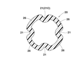
図5は、図3のV-V線の拡大断面図である。図5に示されるように、剛性低下部21(スリット21A)は、第2部分20のシャフト周方向に等間隔で形成されても良い。このような実施態様によれば、第2部分20の各爪片26の曲げ剛性等が均一化され、ひいては、各爪片26の弾性復元力がシャフト2の内周面2iの周方向にバランス良く作用する。したがって、本実施形態の錘部材5は、シャフト2の空間i内でより安定的に保持され得る。
[Spacing of reduced rigidity parts (Fig. 5)]
Fig. 5 is an enlarged cross-sectional view of line V-V in Fig. 3. As shown in Fig. 5, the reduced rigidity portions 21 (
図5では、そのような例として、同一形状の4本のスリット21Aが、シャフト周方向に90°間隔で配置されている。また、錘部材5がシャフト2の空間iに装着されたときに、第2部分20の重心g(図5に便宜的に示す)がシャフト軸中心線上に位置するように形成されるのが望ましい。これにより、上記作用がより確実に得られる。
In FIG. 5, as an example of such a configuration, four
さらに、図5に示されるように、各爪片26のシャフト軸方向と直角な断面積は、第2端2bの側に向かって小さく形成されても良い。具体的には、各爪片26のシャフト周方向の長さa、及び/又は、各爪片26のシャフト径方向の厚さbが、シャフト2の第2端2bの側に向かって段階的に、又は、連続的に小さくなるように形成されても良い。このような態様では、第2部分20の重心が、シャフト軸方向において、第1端2aの側に位置するので、カウンターバランスの効果がより一層高められる。
Furthermore, as shown in FIG. 5, the cross-sectional area of each
[錘部材の他の実施形態(図6)]
図6は、錘部材5の他の実施形態の縦断面図である。この錘部材5では、第1部分10の外径D1が、第2端2bの側に向かって漸増している点で、図3の形態と異なっている。したがって、この第1部分10は、円錐状外面を備える。また、錘部材5は、前記円錐状外面が、第1部分10から第2部分20に亘って連続するように形成されている。このような錘部材5は、第1内径d1が異なる様々なシャフトsに装着可能であり、高い汎用性を備える。
[Another embodiment of the weight member (FIG. 6)]
Fig. 6 is a vertical cross-sectional view of another embodiment of the
[錘部材のさらに他の実施形態(図6)]
図6に示されるように、この錘部材5は、第1部分10の外表面に、シャフト径方向に突出し、かつ、シャフト2の内周面2iに当接可能な少なくとも一つの突起103が形成されている。突起103は、例えば、係合部7に向かって突出高さが漸増している。これにより、突起103は、シャフト2へ容易に挿入することができる。突起103は、好ましくは、シャフト周方向に、等間隔で複数設けられるのが望ましい。
[Still another embodiment of the weight member (FIG. 6)]
6, the
この例の錘部材5は、第1部分10がシャフト2の空間iに配置されたときに、突起103、及び/又は、シャフト2の内周面2iが変形し、その部分で局所的に高い接触圧力が得られる。したがって、この錘部材5は、シャフト2の内部でより確実に固定され得る。なお、突起103は、図3の形状の錘部材5に適用可能であるのは言うまでもない。
When the
[錘部材のさらに他の実施形態(図7)]
図7は、錘部材5のさらに他の実施形態の縦断面図である。この錘部材5では、第2部分20が、小径部28を含む点で、図3の形態と異なっている。小径部28は、第2部分20の第2端2bの側の端部20eに形成されている。また、錘部材5がシャフト2に配置される前の状態において、小径部28の外径D4は、シャフト2の第1内径d1よりも小さく形成されている。
[Still another embodiment of the weight member (FIG. 7)]
Fig. 7 is a vertical cross-sectional view of yet another embodiment of the
好ましい態様では、小径部28は、第2端2bの側に向かって外径が漸減するようなテーパ状とされる。また、スリット21Aは、大径部22から小径部28に亘って形成されている。
In a preferred embodiment, the
図7の錘部材5によれば、シャフト2への錘部材5の挿入がさらに容易になり、ゴルフクラブ1の生産性が向上する。すなわち、この錘部材5は、第2部分20の端部20eが上述の小径部28とされているため、シャフト2への錘部材5の挿入工程時、予め第2部分20に外力を与えてその外径を小さくしておく必要はない。すなわち、小径部28をシャフト2の空間iに挿入していくと、大径部22の外周面は、シャフト2の内周面2iと接触し、この内周面2iからシャフト径方向の内側に向く外力を受ける。これにより、第2部分20は、その外径を徐々に縮めながらシャフト2の空間iに容易に挿入され得る。
The
[錘部材のさらに他の実施形態(図8)]
図8は、錘部材5のさらに他の実施形態の縦断面図である。図9は、図8のIX-IX線断面図である。図8及び図9に示されるように、この錘部材5では、第2部分20の剛性低下部21が、スリット21Aに代えて、薄肉部21Bとされている。薄肉部21Bは、例えば、爪片26、26の間を、爪片26よりも小さい肉厚で連結してシャフト軸方向に延びている。この例では、薄肉部21Bのシャフト径方向の肉厚は、爪片26の肉厚の50%以下とされている。
[Still another embodiment of the weight member (FIG. 8)]
Fig. 8 is a vertical cross-sectional view of yet another embodiment of the
上述のような薄肉部21Bは、外力が与えられるとそれ自身が容易に撓むことができる。したがって、この実施形態においても、スリット21Aの場合と同様、第2部分20に外力を与えると、大径部22の外径を小さく弾性変形させることができる。また、剛性低下部21が薄肉部21Bの場合、各爪片26には、スリット21Aの場合よりも大きな強く弾性復元力を生じさせることが可能である。したがって、錘部材5の位置がより一層安定する。
The thin-
上記実施形態では、薄肉部21Bは、第2部分20のシャフト径方向の外側の表面から凹んだ位置で爪片26を連結している。他の態様では、薄肉部21Bは、第2部分20のシャフト径方向の内側の表面から凹んだ位置に設けられても良い。
In the above embodiment, the thin-
図10は、錘部材5のさらに他の実施形態として、第2部分20のシャフト軸方向と直交する断面図(図8のIX-IX線断面図相当)である。図10に示されるように、この錘部材5では、第2部分20の剛性低下部21が、スリット21Aに代えて、溝21Cとされている。溝21Cは、爪片26、26の間でシャフト径方向に凹んでシャフト軸方向に延びている。また、溝21Cは、例えば、爪片26の間を、爪片26の肉厚以下の肉厚で連結している。
Figure 10 is a cross-sectional view (corresponding to the cross-sectional view of line IX-IX in Figure 8) of the
したがって、この実施形態においても、スリット21Aの場合と同様、第2部分20に外力を与えると、溝21Cが局所的に変形し、大径部22の外径を小さく弾性変形させることができる。また、剛性低下部21が溝21Cの場合、各爪片26には、スリット21Aの場合に比べて、より大きな強く弾性復元力を生じさせることが可能である。したがって、錘部材5の位置がより一層安定する。
Therefore, in this embodiment, as in the case of
なお、剛性低下部21は、スリット21Aとともに、薄肉部21Bや溝21Cを用いても良い。
The reduced
以上、本発明の実施形態が詳細に説明されたが、本発明は、上記の具体的な開示に限定されるものではなく、特許請求の範囲に記載された技術的思想の範囲内において、種々変更して実施することができる。 Although the embodiments of the present invention have been described in detail above, the present invention is not limited to the specific disclosure above, and can be implemented with various modifications within the scope of the technical ideas described in the claims.
1 ゴルフクラブ
2 シャフト
2a シャフトの第1端
2b シャフトの第2端
2i シャフトの内周面
3 ゴルフクラブヘッド
5 錘部材
6 挿入部
7 係合部
10 挿入部の第1部分
20 挿入部の第2部分
20A 拡径部分
21 剛性低下部
21A スリット
21B 薄肉部
21C 溝
22 大径部
24 中空部
26 爪片
28 小径部
101 錘本体
102 弾性体
103 突起
Claims (13)
第1端と第2端とを有し、かつ、内部に空間を有するパイプ状のシャフトと、
前記シャフトの前記第1端の側に装着された錘部材と、
前記シャフトの前記第2端の側に設けられたゴルフクラブヘッドとを含み、
前記錘部材は、前記シャフトの前記空間に配された挿入部と、前記シャフトの前記第1端に係合するように前記空間の外に位置する係合部とを含み、
前記挿入部は、前記第1端の側の第1部分と、前記第2端の側の第2部分とを含み、
前記第1部分は、前記シャフトの前記第1端での内径である第1内径よりも小さい外径を有し、
前記第2部分は、前記シャフトに配置される前の状態において、前記第1内径よりも大きい外径を有する大径部と、外力を受けることで、前記大径部の前記外径が小さくなるように前記第2部分を弾性変形させる少なくとも一つの剛性低下部とを備え、
前記第2部分は、弾性変形した状態で前記空間に配されており、
前記大径部は、その弾性復元力によって、少なくとも一部が前記シャフトの内周面に当接しており、
前記剛性低下部は、シャフト軸方向に延びるスリットを含み、
前記第2部分は、前記シャフトに配置される前の状態において、前記第2端の側に向かって外径が増加する拡径部分を含み、
前記拡径部分は、前記第1部分から前記第2端の側に向かって外径が漸増している、
ゴルフクラブ。 A golf club,
a pipe-shaped shaft having a first end and a second end and having a space therein;
A weight member attached to the first end of the shaft;
a golf club head provided on the second end of the shaft,
the weight member includes an insertion portion disposed in the space of the shaft and an engagement portion located outside the space so as to engage with the first end of the shaft,
the insertion portion includes a first portion on the first end side and a second portion on the second end side,
the first portion has an outer diameter that is smaller than a first inner diameter, the first diameter being an inner diameter of the shaft at the first end;
the second portion includes a large diameter portion having an outer diameter larger than the first inner diameter before being disposed on the shaft, and at least one reduced rigidity portion that elastically deforms the second portion such that the outer diameter of the large diameter portion becomes smaller when subjected to an external force,
The second portion is disposed in the space in an elastically deformed state,
At least a portion of the large diameter portion abuts against the inner circumferential surface of the shaft due to its elastic restoring force ,
The reduced-rigidity portion includes a slit extending in the shaft axial direction,
the second portion includes an expanded diameter portion having an outer diameter increasing toward the second end before being placed on the shaft,
The enlarged diameter portion has an outer diameter that gradually increases from the first portion toward the second end .
Golf club.
第1端と第2端とを有し、かつ、内部に空間を有するパイプ状のシャフトと、
前記シャフトの前記第1端の側に装着された錘部材と、
前記シャフトの前記第2端の側に設けられたゴルフクラブヘッドとを含み、
前記錘部材は、前記シャフトの前記空間に配された挿入部と、前記シャフトの前記第1端に係合するように前記空間の外に位置する係合部とを含み、
前記挿入部は、前記第1端の側の第1部分と、前記第2端の側の第2部分とを含み、
前記第1部分は、前記シャフトの前記第1端での内径である第1内径よりも小さい外径を有し、
前記第2部分は、前記シャフトに配置される前の状態において、前記第1内径よりも大きい外径を有する大径部と、外力を受けることで、前記大径部の前記外径が小さくなるように前記第2部分を弾性変形させる少なくとも一つの剛性低下部とを備え、
前記第2部分は、弾性変形した状態で前記空間に配されており、
前記大径部は、その弾性復元力によって、少なくとも一部が前記シャフトの内周面に当接しており、
前記第2部分は、前記シャフトに配置される前の状態において、前記第2端の側に向かって外径が増加する拡径部分と、前記拡径部分の前記第2端の側に、前記第2端の側に向かって外径が漸減する小径部とを含む、
ゴルフクラブ。 A golf club,
a pipe-shaped shaft having a first end and a second end and having a space therein;
A weight member attached to the first end of the shaft;
a golf club head provided on the second end of the shaft,
the weight member includes an insertion portion disposed in the space of the shaft and an engagement portion located outside the space so as to engage with the first end of the shaft,
the insertion portion includes a first portion on the first end side and a second portion on the second end side,
the first portion has an outer diameter that is smaller than a first inner diameter, the first diameter being an inner diameter of the shaft at the first end;
the second portion includes a large diameter portion having an outer diameter larger than the first inner diameter before being disposed on the shaft, and at least one reduced rigidity portion that elastically deforms the second portion such that the outer diameter of the large diameter portion becomes smaller when subjected to an external force,
The second portion is disposed in the space in an elastically deformed state,
At least a portion of the large diameter portion abuts against the inner circumferential surface of the shaft due to its elastic restoring force,
The second portion includes, before being placed on the shaft, an expanded diameter portion whose outer diameter increases toward the second end, and a small diameter portion, located on the second end side of the expanded diameter portion, whose outer diameter gradually decreases toward the second end .
Golf club.
前記各爪片のシャフト軸方向と直角な断面積は、前記第2端の側に向かって小さくなっている、請求項1、3、4及び5のいずれかに記載のゴルフクラブ。 The second portion is divided by the plurality of slits into a plurality of deformable claw pieces extending in the shaft axial direction,
6. The golf club according to claim 1, wherein a cross-sectional area of each of said claws perpendicular to the shaft axis direction becomes smaller toward said second end.
前記錘部材は、前記シャフトの前記空間内に配される挿入部と、前記シャフトの前記第1端に係合するように前記空間外に位置する係合部とを含み、
前記挿入部は、前記第1端の側の第1部分と、前記第2端の側の第2部分とを含み、
前記第2部分は、外力を受けることで、その外径が小さくなるように前記第2部分を弾性変形させるための少なくとも一つの剛性低下部を備えており、
前記剛性低下部は、シャフト軸方向に延びるスリットを含み、
前記第2部分は、前記シャフトに配置される前の状態において、前記第2端の側に向かって外径が増加する拡径部分を含み、
前記拡径部分は、前記第1部分から前記第2端の側に向かって外径が漸増している、
ゴルフクラブ用の錘部材。 A weight member for a golf club, the weight member having a first end and a second end, and attached to a side of the first end of a pipe-shaped shaft having an internal space,
the weight member includes an insertion portion disposed within the space of the shaft and an engagement portion located outside the space so as to engage with the first end of the shaft,
the insertion portion includes a first portion on the first end side and a second portion on the second end side,
the second portion includes at least one reduced-rigidity portion for elastically deforming the second portion so that an outer diameter of the second portion is reduced when the second portion receives an external force;
The reduced-rigidity portion includes a slit extending in the shaft axial direction,
the second portion includes an expanded diameter portion having an outer diameter increasing toward the second end before being placed on the shaft,
The enlarged diameter portion has an outer diameter that gradually increases from the first portion toward the second end.
A weight component for a golf club .
前記錘部材は、前記シャフトの前記空間内に配される挿入部と、前記シャフトの前記第1端に係合するように前記空間外に位置する係合部とを含み、
前記挿入部は、前記第1端の側の第1部分と、前記第2端の側の第2部分とを含み、
前記第2部分は、外力を受けることで、その外径が小さくなるように前記第2部分を弾性変形させるための少なくとも一つの剛性低下部を備えており、
前記第2部分は、前記シャフトに配置される前の状態において、前記第2端の側に向かって外径が増加する拡径部分と、前記拡径部分の前記第2端の側に、前記第2端の側に向かって外径が漸減する小径部とを含む、
ゴルフクラブ用の錘部材。 A weight member for a golf club, the weight member having a first end and a second end, and attached to a side of the first end of a pipe-shaped shaft having an internal space,
the weight member includes an insertion portion disposed within the space of the shaft and an engagement portion located outside the space so as to engage with the first end of the shaft,
the insertion portion includes a first portion on the first end side and a second portion on the second end side,
the second portion includes at least one reduced-rigidity portion for elastically deforming the second portion so that an outer diameter of the second portion is reduced when the second portion receives an external force ;
The second portion includes, before being placed on the shaft, an expanded diameter portion whose outer diameter increases toward the second end, and a small diameter portion, located on the second end side of the expanded diameter portion, whose outer diameter gradually decreases toward the second end .
A weight component for a golf club.
Priority Applications (3)
| Application Number | Priority Date | Filing Date | Title |
|---|---|---|---|
| JP2021005975A JP7608841B2 (en) | 2021-01-18 | 2021-01-18 | Golf club and weight member for golf club |
| US17/567,233 US12179074B2 (en) | 2021-01-18 | 2022-01-03 | Golf club and weight piece for golf club |
| US18/960,588 US20250083003A1 (en) | 2021-01-18 | 2024-11-26 | Golf club and weight piece for golf club |
Applications Claiming Priority (1)
| Application Number | Priority Date | Filing Date | Title |
|---|---|---|---|
| JP2021005975A JP7608841B2 (en) | 2021-01-18 | 2021-01-18 | Golf club and weight member for golf club |
Publications (2)
| Publication Number | Publication Date |
|---|---|
| JP2022110513A JP2022110513A (en) | 2022-07-29 |
| JP7608841B2 true JP7608841B2 (en) | 2025-01-07 |
Family
ID=82405918
Family Applications (1)
| Application Number | Title | Priority Date | Filing Date |
|---|---|---|---|
| JP2021005975A Active JP7608841B2 (en) | 2021-01-18 | 2021-01-18 | Golf club and weight member for golf club |
Country Status (2)
| Country | Link |
|---|---|
| US (2) | US12179074B2 (en) |
| JP (1) | JP7608841B2 (en) |
Families Citing this family (1)
| Publication number | Priority date | Publication date | Assignee | Title |
|---|---|---|---|---|
| JP7608841B2 (en) * | 2021-01-18 | 2025-01-07 | 住友ゴム工業株式会社 | Golf club and weight member for golf club |
Citations (2)
| Publication number | Priority date | Publication date | Assignee | Title |
|---|---|---|---|---|
| US20170182389A1 (en) | 2015-12-29 | 2017-06-29 | Acushnet Company | System and method for weighting a golf club |
| JP6601584B1 (en) | 2019-04-26 | 2019-11-06 | 住友ゴム工業株式会社 | Golf club and weight member for golf club |
Family Cites Families (13)
| Publication number | Priority date | Publication date | Assignee | Title |
|---|---|---|---|---|
| JPS5440146Y2 (en) * | 1975-05-19 | 1979-11-27 | ||
| JPH0342946Y2 (en) * | 1986-01-22 | 1991-09-09 | ||
| US20030207720A1 (en) * | 2002-05-03 | 2003-11-06 | Joseph Sery | Swing weight plug and method for manufacturing a golf club having a pre-selected swing weight |
| JP4507266B1 (en) * | 2009-11-20 | 2010-07-21 | 央 軽部 | Weight grip structure and golf club |
| US8348783B2 (en) * | 2010-04-15 | 2013-01-08 | Soracco Peter L | Butt-mounted shaft extension for a golf club |
| US9539481B2 (en) * | 2014-06-11 | 2017-01-10 | Gisle Solhaug | Selectable weight assembly for golf clubs |
| US20160016057A1 (en) * | 2014-07-15 | 2016-01-21 | High Cedar Enterprise Co., Ltd. | Counterweight assembly |
| US11691059B2 (en) * | 2015-05-28 | 2023-07-04 | Karsten Manufacturing Corporation | Adjustable putter shaft stiffener |
| US9616307B1 (en) * | 2015-10-21 | 2017-04-11 | Kai-Ping Chiang | Adjustable-counterbalanced handle |
| US10010773B1 (en) * | 2017-05-31 | 2018-07-03 | Scott J. Pugliese | Grip assemblies and related methods |
| US20180361214A1 (en) * | 2017-06-16 | 2018-12-20 | John Johnson | Golf grip with snap-in weightable cap portion |
| JP7608841B2 (en) * | 2021-01-18 | 2025-01-07 | 住友ゴム工業株式会社 | Golf club and weight member for golf club |
| US12076626B2 (en) * | 2021-08-20 | 2024-09-03 | Topgolf Callaway Brands Corp. | Removable weight for golf club shaft |
-
2021
- 2021-01-18 JP JP2021005975A patent/JP7608841B2/en active Active
-
2022
- 2022-01-03 US US17/567,233 patent/US12179074B2/en active Active
-
2024
- 2024-11-26 US US18/960,588 patent/US20250083003A1/en active Pending
Patent Citations (2)
| Publication number | Priority date | Publication date | Assignee | Title |
|---|---|---|---|---|
| US20170182389A1 (en) | 2015-12-29 | 2017-06-29 | Acushnet Company | System and method for weighting a golf club |
| JP6601584B1 (en) | 2019-04-26 | 2019-11-06 | 住友ゴム工業株式会社 | Golf club and weight member for golf club |
Also Published As
| Publication number | Publication date |
|---|---|
| US20220226704A1 (en) | 2022-07-21 |
| US12179074B2 (en) | 2024-12-31 |
| US20250083003A1 (en) | 2025-03-13 |
| JP2022110513A (en) | 2022-07-29 |
Similar Documents
| Publication | Publication Date | Title |
|---|---|---|
| US5899823A (en) | Ball bat with insert | |
| KR101880329B1 (en) | Fastener | |
| WO2011093299A1 (en) | Clamp | |
| KR20120003921A (en) | Instrument assembly with hard cap | |
| JP2013509556A (en) | Push-in fastener assembly | |
| JP7608841B2 (en) | Golf club and weight member for golf club | |
| JP6601584B1 (en) | Golf club and weight member for golf club | |
| WO2017013797A1 (en) | Fastener | |
| JP5587951B2 (en) | Method for manufacturing electric motor having balance adjustment structure of rotor | |
| JP2003319624A (en) | Motor and its manufacturing method | |
| CN114746296B (en) | Double rolling convex-lobe non-pressure jointing guide tube | |
| JP5855303B1 (en) | Spacer and spacer design method | |
| JP7683354B2 (en) | Golf club and weight member for golf club | |
| EP1770310A2 (en) | Speed changing operation apparatus for vehicle | |
| JP2024149227A (en) | Golf club and weight member for golf club | |
| JP2010125139A (en) | Golf club | |
| US20010050203A1 (en) | Dynamic damper | |
| JP2021071149A (en) | Fastener | |
| JP5871555B2 (en) | Pipe connection structure and cleaning tool using the same | |
| JP4606491B2 (en) | Golf club grip | |
| JP7280813B2 (en) | Fastener | |
| JP7518527B2 (en) | Golf club grip and method for manufacturing golf club grip | |
| JP5429484B2 (en) | Anti-vibration bush | |
| JP2000346112A (en) | Spring seat rubber | |
| JP7396074B2 (en) | Applicator manufacturing method and insertion device |
Legal Events
| Date | Code | Title | Description |
|---|---|---|---|
| A621 | Written request for application examination |
Free format text: JAPANESE INTERMEDIATE CODE: A621 Effective date: 20231121 |
|
| A977 | Report on retrieval |
Free format text: JAPANESE INTERMEDIATE CODE: A971007 Effective date: 20240830 |
|
| A131 | Notification of reasons for refusal |
Free format text: JAPANESE INTERMEDIATE CODE: A131 Effective date: 20240903 |
|
| A521 | Request for written amendment filed |
Free format text: JAPANESE INTERMEDIATE CODE: A523 Effective date: 20241025 |
|
| TRDD | Decision of grant or rejection written | ||
| A01 | Written decision to grant a patent or to grant a registration (utility model) |
Free format text: JAPANESE INTERMEDIATE CODE: A01 Effective date: 20241119 |
|
| A61 | First payment of annual fees (during grant procedure) |
Free format text: JAPANESE INTERMEDIATE CODE: A61 Effective date: 20241202 |
|
| R150 | Certificate of patent or registration of utility model |
Ref document number: 7608841 Country of ref document: JP Free format text: JAPANESE INTERMEDIATE CODE: R150 |