JP7608832B2 - Machine learning device and failure judgment device - Google Patents
Machine learning device and failure judgment device Download PDFInfo
- Publication number
- JP7608832B2 JP7608832B2 JP2021000767A JP2021000767A JP7608832B2 JP 7608832 B2 JP7608832 B2 JP 7608832B2 JP 2021000767 A JP2021000767 A JP 2021000767A JP 2021000767 A JP2021000767 A JP 2021000767A JP 7608832 B2 JP7608832 B2 JP 7608832B2
- Authority
- JP
- Japan
- Prior art keywords
- aviation obstruction
- learning model
- obstruction light
- machine learning
- learning
- Prior art date
- Legal status (The legal status is an assumption and is not a legal conclusion. Google has not performed a legal analysis and makes no representation as to the accuracy of the status listed.)
- Active
Links
Images


Landscapes
- Circuit Arrangement For Electric Light Sources In General (AREA)
Description
本発明は、機械学習装置及び故障判定装置に関する。 The present invention relates to a machine learning device and a fault determination device.
送電鉄塔の航空障害灯は、昼間は照度を高く、夜間は照度を低く設定している。しかし、落雷等により設定にトラブルが生じ、夜間も照度が高くなってしまったために、航空障害灯の設置箇所の近隣住民から航空障害灯を設置する事業者に対して、問い合わせがもたらされることがある。また、発電所煙突の航空障害灯についても同様に、故障で点灯しなくなることがある。 The aviation obstruction lights on power transmission towers are set to high brightness during the day and low brightness at night. However, problems with the settings due to lightning strikes and other factors can cause the brightness to be too high at night, which can lead to inquiries from residents living near the installation site to the companies that install the lights. Similarly, aviation obstruction lights on power plant chimneys can also malfunction and stop working.
例えば、特許文献1は、航空障害灯の故障を検出するため、所定位置に設けられた航空障害灯を撮像する撮像手段と、当該撮像手段から航空障害灯までの距離および方向に係る位置情報に基づいて、撮像手段の少なくとも方向及びフォーカスを調整して、航空障害灯の故障の判定に用いられる判定用画像を取得するよう撮像手段を制御する撮像制御手段と、判定用画像から航空障害灯の判定用発光強度を算出する発光強度算出手段と、判定用発光強度と閾値とを比較して航空障害灯の故障を判定する故障判定手段と、を有する故障検出システムに係る技術を開示している。 For example, Patent Document 1 discloses technology relating to a failure detection system that includes an imaging means for imaging an aviation obstruction light installed at a predetermined position in order to detect a failure of the aviation obstruction light, an imaging control means for controlling the imaging means to adjust at least the direction and focus of the imaging means based on position information relating to the distance and direction from the imaging means to the aviation obstruction light to obtain a judgment image used to judge the failure of the aviation obstruction light, an emission intensity calculation means for calculating the judgment emission intensity of the aviation obstruction light from the judgment image, and a failure judgment means for comparing the judgment emission intensity with a threshold value to judge the failure of the aviation obstruction light.
しかし、特許文献1に係る技術においては、航空障害灯の故障を判定するにあたり、判定用画像から取得される判定用発光強度と、閾値との比較を行っているが、航空障害灯自体の照度が同一であっても、例えば天候や時刻等の航空障害灯を取り巻く環境に応じて、判定用画像が異なることに起因して、判定用発光強度が変化してしまうことに対応していなかった。 However, in the technology disclosed in Patent Document 1, when determining whether an aviation obstruction light is faulty, the light intensity for determination obtained from the image for determination is compared with a threshold value. However, this technology does not address the fact that even if the illuminance of the aviation obstruction light itself is the same, the light intensity for determination changes depending on the environment surrounding the aviation obstruction light, such as the weather or time, due to the image for determination being different.
本発明は、航空障害灯を取り巻く環境が変化しても、より正確に当該航空障害灯の故障を判定することが可能な機械学習装置及び故障判定装置を提供することを目的とする。 The present invention aims to provide a machine learning device and a fault determination device that can more accurately determine faults in aviation obstruction lights even when the environment surrounding the lights changes.
前記目的を達成するため、本発明は、次に記載する構成を備えている。 To achieve the above objective, the present invention has the following configuration.
(1) 航空障害灯の故障を判定するための学習モデルを構築する機械学習装置であって、前記航空障害灯を撮像した写真を入力データとして取得する入力データ取得手段と、前記写真において被写体とされる前記航空障害灯の故障状態の判定結果をラベルとして取得するラベル取得手段と、前記入力データと前記ラベルとの組を教師データとして教師あり学習を行うことにより、前記航空障害灯を被写体として含む新たな写真における当該航空障害灯の故障状態を判定するための学習モデルを構築する学習モデル構築手段と、を備える機械学習装置。 (1) A machine learning device that constructs a learning model for determining whether an aviation obstruction light is faulty, the machine learning device comprising: an input data acquisition means that acquires a photograph of the aviation obstruction light as input data; a label acquisition means that acquires, as a label, a determination result of the fault state of the aviation obstruction light that is the subject of the photograph; and a learning model construction means that performs supervised learning using a pair of the input data and the label as training data to construct a learning model for determining the fault state of the aviation obstruction light in a new photograph that includes the aviation obstruction light as the subject.
(1)によれば、航空障害灯を取り巻く環境が変化しても、より正確に当該航空障害灯の故障を判定することが可能な機械学習装置を提供することが可能となる。 (1) makes it possible to provide a machine learning device that can more accurately determine whether an aviation obstruction light is faulty, even if the environment surrounding the obstruction light changes.
(2) (1)に記載の機械学習装置において、前記学習モデル構築手段は、複数の前記航空障害灯に対して一つの学習モデルを構築することが好ましい。 (2) In the machine learning device described in (1), it is preferable that the learning model construction means constructs one learning model for multiple aviation obstruction lights.
(2)によれば、複数の航空障害灯の故障を判定する学習モデルを一つにまとめることが可能となる。 According to (2), it is possible to consolidate into one learning model that detects the failure of multiple aviation obstruction lights.
(3) (1)に記載の機械学習装置において、前記学習モデル構築手段は、複数の前記航空障害灯の各々に対して一つずつ学習モデルを構築することが好ましい。 (3) In the machine learning device described in (1), it is preferable that the learning model construction means constructs a learning model for each of the multiple aviation obstruction lights.
(3)によれば、航空障害灯毎に学習モデルを構築することにより、よりきめ細かく航空障害灯の故障を判定することが可能となる。 According to (3), by constructing a learning model for each aviation obstruction light, it is possible to determine the malfunction of the aviation obstruction light in more detail.
(4) (1)から(3)までのいずれか1に記載の機械学習装置で構築した前記学習モデルを用いた故障判定装置であって、前記写真と前記学習モデルとに基づいて、前記航空障害灯の故障状態を判定する故障状態判定手段と、を備える故障判定装置。 (4) A fault determination device using the learning model constructed by the machine learning device according to any one of (1) to (3), comprising a fault condition determination means for determining a fault condition of the aviation obstruction light based on the photograph and the learning model.
(4)によれば、航空障害灯を取り巻く環境が変化しても、より正確に当該航空障害灯の故障を判定することが可能な故障判定装置を提供することが可能となる。 (4) It is possible to provide a failure determination device that can more accurately determine the failure of an aviation obstruction light even if the environment surrounding the aviation obstruction light changes.
本発明によれば、航空障害灯を取り巻く環境が変化しても、より正確に当該航空障害灯の故障を判定することが可能となる。 The present invention makes it possible to more accurately determine whether an aviation obstruction light is faulty, even if the environment surrounding the light changes.
以下、本発明の実施形態について、図1~図6を参照することにより説明する。 The following describes an embodiment of the present invention with reference to Figures 1 to 6.
〔1 実施形態の構成〕
まず、本実施形態に係る故障判定システム100の構成について説明する。図1は、本実施形態に係る故障判定システムを示すブロック図である。故障判定システム100は、図1に示すように、機械学習装置10及び故障判定装置20を備えている。
[Configuration of 1 embodiment]
First, a configuration of a
ここで、機械学習装置10と故障判定装置20とは1対1の組とされて、通信可能に接続されている。なお、図1では図示しないが、機械学習装置10と故障判定装置20とはネットワークを介して、互いに接続されていてもよい。ネットワークは、例えば、LAN(Local Area Network)や、インターネット、公衆電話網、あるいは、これらの組み合わせである。ネットワークにおける具体的な通信方式や、有線接続及び無線接続のいずれであるか等については、特に限定されない。あるいは、機械学習装置10と故障判定装置20とは、ネットワークを用いた通信ではなく、接続部を介して直接接続してもよい。
Here, the
機械学習装置10は、教師あり学習により、故障判定装置20で用いる学習モデルを構築する。そのため、機械学習装置10は、図1に示すように、学習部11を備える。
The
学習部11は、航空障害灯の故障を判定するための学習モデルを構築する。なお、この航空障害灯の故障としては、例えば夜間に照度が高すぎたり、あるいは、逆に照度が低すぎたり(そもそも航空障害灯を点灯できないために、照度が0であることを含む)することが挙げられる。
The
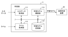
図2は、学習部11の機能ブロック図である。学習部11は、図2に示すように、入力データ取得部111、ラベル取得部112、学習モデル構築部113、学習モデル記憶部114を備える。
Figure 2 is a functional block diagram of the
入力データ取得部111は、航空障害灯を被写体として含む写真を入力データとして取得する。ここで、航空障害灯を被写体として含む写真は、当該航空障害灯を所定の地点、所定の角度から、所定の時間(例えば、午前0時、午前1時、午前2時・・・午後0時、午後1時、午後2時・・・午後11時等の定時)に撮像した写真であることが好ましい。更に、航空障害灯を撮像した時点での天気が、晴天、曇天、雨天の各々の場合の写真が含まれることが好ましい。
The input
なお、この入力データとしての写真は、1つの航空障害灯を被写体とする複数の写真であってもよく、各々が互いに異なる航空障害灯を被写体とする複数の写真であってもよい。 The photographs used as input data may be multiple photographs with one aviation obstruction light as their subject, or multiple photographs each with a different aviation obstruction light as their subject.
ラベル取得部112は、上記の写真に被写体として含まれる航空障害灯の故障状態の判定結果をラベルとして取得する。なお、この判定結果は、航空障害灯を設置した事業者による実際の判定結果であって、航空障害灯が正常か異常かの二値で表される判定結果であることが好ましい。
The
学習モデル構築部113は、上記の入力データと、上記のラベルとの組を教師データとして教師あり学習を行うことにより、航空障害灯を被写体として含む写真に含まれる当該航空障害灯の故障状態を判定するための学習モデルを構築し、構築した学習モデルを、故障判定装置20に送信する。
The learning
なお、本実施形態においては、上記の入力データとしての写真が、各々が互いに異なる航空障害灯を被写体とする複数の写真である場合、複数の航空障害灯に対して1つの学習モデルを構築する。 In this embodiment, if the above-mentioned input data consists of multiple photographs each of which has a different aviation obstruction light as its subject, one learning model is constructed for the multiple aviation obstruction lights.
学習モデル構築部113は、例として、サポート・ベクター・マシン(Support Vector Machine、以下SVMともいう)を用いて実現することが可能である。
The learning
この場合、学習モデル構築部113は、上記のラベルとして、航空障害灯が正常か異常かに係る二値化されたラベルを用いると共に、上記の入力データを含む空間を、上記の特定の故障状態に該当するか否かに関して、マージンが最大となるように分離する超平面を算出する。さらに、学習モデル構築部113は、この超平面の係数を、後述の故障判定装置20が故障状態判定のために用いる学習モデルのパラメータとすることが可能である。
In this case, the learning
学習モデル記憶部114は、学習モデル構築部113が構築した学習モデルを記憶する。
The learning
機械学習装置10は、上記の構成を有することにより、航空障害灯の故障を判定するための学習モデルを構築する。
By having the above configuration, the
図3は、故障判定装置20の機能ブロック図である。故障判定装置20は、制御部21と、記憶部22と、表示部23とを備える。
Figure 3 is a functional block diagram of the
制御部21は、故障判定装置20の全体を制御する部分であり、各種プログラムを、ROM、RAM、フラッシュメモリ又はハードディスク(HDD)等の記憶領域から適宜読み出して実行することにより、本実施形態における各種機能を実現している。制御部21は、CPUであってよい。制御部21は、写真取得部211、故障状態判定部212を備える。
The
写真取得部211は、機械学習装置10で機械学習をした際に用いた教師データに含まれる写真とは別個に、航空障害灯を被写体として含む新たな写真を取得する。例えば、作業員が、故障判定装置20に備わるキーボードやマウス等の入力デバイスを操作することにより、故障判定装置20に航空障害灯を被写体として含む新たな写真を読み込ませた後、写真取得部211は、読み込ませた新たな写真を取得してもよい。
The
故障状態判定部212は、写真取得部211によって取得された写真と学習モデルとに基づいて、当該写真において被写体となっている航空障害灯の故障状態を判定する。
The fault
記憶部22は、機械学習装置10から取得した学習モデルを記憶する。また、記憶部22は、写真取得部211によって取得された航空障害灯を被写体として含む写真を記憶してもよい。
The
表示部23は、故障状態判定部212による判定結果を表示するモニタである。
The
故障判定装置20は、上記の構成を備えることにより、航空障害灯を被写体として含む写真に基づいて、当該航空障害灯の故障を判定することが可能となる。
By being equipped with the above-mentioned configuration, the
〔2 実施形態の動作〕
次に、本実施形態に係る故障判定システム100の動作について説明する。まず、図4を参照し、機械学習装置10の動作について説明する。
2. Operation of the embodiment
Next, a description will be given of the operation of the
〔2.1 機械学習装置10の動作〕
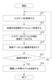
図4は、学習部11の動作を示すフローチャートである。
ステップS11において、入力データ取得部111が、航空障害灯を被写体として含む写真を入力データとして取得する。
2.1 Operation of the
FIG. 4 is a flowchart showing the operation of the
In step S11, the input
ステップS12において、ラベル取得部112が、ステップS11において取得された写真において被写体として含まれる航空障害灯の故障状態の判定結果をラベルとして取得する。
In step S12, the
ステップS13において、学習モデル構築部113は、入力データとラベルとの組を教師データとする。
In step S13, the learning
ステップS14において、学習モデル構築部113は、ステップS13の教師データを用いて教師あり学習を行う。
In step S14, the learning
ステップS15において、機械学習が終了した場合(S15:YES)には、処理はステップS16に移行する。機械学習がまだ終了していない場合(S15:NO)には、処理はステップS11に移行する。 If machine learning has ended in step S15 (S15: YES), the process proceeds to step S16. If machine learning has not yet ended (S15: NO), the process proceeds to step S11.
ステップS16において、学習モデル構築部113は、構築した学習モデルを故障判定装置20に送信する。その後、全ての処理を終了する。
In step S16, the learning
〔2.2 故障判定装置20の動作〕
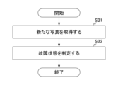
次に、図5を参照し、故障判定装置20の動作について説明する。
2.2 Operation of the
Next, the operation of the
ステップS51において、写真取得部211が、航空障害灯を被写体とする新たな写真を取得する。
In step S51, the
ステップS52において、故障状態判定部212は、写真取得部211によって取得された写真と学習モデルとに基づいて、当該写真に被写体として含まれる航空障害灯の故障状態を判定する。その後、全ての処理を終了する。
In step S52, the failure
〔3 変形例〕
以上、本発明の実施形態について説明したが、本発明は前述した実施形態に限るものではない。また、本実施形態に記載された効果は、本発明から生じる最も好適な効果を列挙したに過ぎず、本発明による効果は、本実施形態に記載されたものに限定されるものではない。
[3 Modifications]
Although the embodiment of the present invention has been described above, the present invention is not limited to the above-described embodiment. Furthermore, the effects described in the present embodiment are merely a list of the most preferable effects resulting from the present invention, and the effects of the present invention are not limited to those described in the present embodiment.
〔3.1 変形例1〕
上記の実施形態において、機械学習装置10と故障判定装置20とを別体として示したが、これには限定されない。例えば、機械学習装置10が故障判定装置20の筐体に組み込まれることにより、故障判定システム100が一体化されて実現される態様としてもよい。
3.1 Modification 1
In the above embodiment, the
〔3.2 変形例2〕
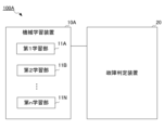
また、上記の実施形態において、複数の航空障害灯に対して一つの学習モデルを構築するが、これには限定されない。図6は、本変形例に係る故障判定システム100Aの構成を示す。図6に示すように、機械学習装置10Aが、各々が各航空障害灯に対応する複数の学習部(第1学習部11A~第n学習部11N)を備えることにより、各々が各航空障害灯に対応する複数の学習モデルを構築してもよい。すなわち、機械学習装置10Aは、複数の航空障害灯の各々に対して一つずつ学習モデルを構築してもよい。
3.2 Modification 2
In the above embodiment, one learning model is constructed for a plurality of aviation obstruction lights, but the present invention is not limited to this. Fig. 6 shows the configuration of a
故障判定システム100による故障判定方法は、ソフトウェアにより実現される。ソフトウェアによって実現される場合には、このソフトウェアを構成するプログラムが、コンピュータにインストールされる。また、これらのプログラムは、リムーバブルメディアに記録されてユーザに配布されてもよいし、ネットワークを介してユーザのコンピュータにダウンロードされることにより配布されてもよい。
The fault determination method by the
10,10A 機械学習装置
11 学習部
20 故障判定装置
21 制御部
22 記憶部
23 表示部
100,100A 故障判定システム
111 入力データ取得部
112 ラベル取得部
113 学習モデル構築部
114 学習モデル記憶部
211 写真取得部
212 故障状態判定部
REFERENCE SIGNS
Claims (4)
前記航空障害灯を撮像した写真を入力データとして取得する入力データ取得手段と、
前記写真において被写体とされる前記航空障害灯の故障状態の判定結果をラベルとして取得するラベル取得手段と、
前記入力データと前記ラベルとの組を教師データとして教師あり学習を行うことにより、前記航空障害灯を被写体として含む新たな写真における当該航空障害灯の故障状態を判定するための学習モデルを構築する学習モデル構築手段と、
を備え、
前記入力データ取得手段は、前記航空障害灯を撮像した時点での天気が晴天、曇天、雨天の各々の場合の写真を入力データとして取得し、
前記ラベル取得手段は、前記航空障害灯を撮像した時点での天気が晴天、曇天、雨天の各々の場合の写真ごとに、前記航空障害灯の故障状態の判定結果を取得し、
前記学習モデル構築手段は、前記航空障害灯を撮像した時点での天気が晴天、曇天、雨天の各々の場合の写真と、当該写真に対応した前記航空障害灯の故障状態の判定結果と、の組を教師データとして教師あり学習を行うことにより、前記学習モデルを構築する機械学習装置。 A machine learning device that constructs a learning model for determining a failure of an aviation obstruction light,
An input data acquisition means for acquiring a photograph of the obstacle light as input data;
a label acquisition means for acquiring a label as a result of a determination of a failure state of the obstacle light that is a subject of the photograph;
a learning model construction means for constructing a learning model for determining a failure state of the aviation obstruction light in a new photograph including the aviation obstruction light as a subject by performing supervised learning using a pair of the input data and the label as training data;
Equipped with
The input data acquisition means acquires, as input data, photographs of the aircraft obstruction lights when the photographs are taken in clear weather, cloudy weather, and rainy weather,
the label acquisition means acquires a determination result of a failure state of the aviation obstruction light for each photograph taken in a sunny, cloudy, or rainy weather at the time when the aviation obstruction light is captured;
The learning model construction means is a machine learning device that constructs the learning model by performing supervised learning using as training data a set of photographs taken of the aviation obstruction light when the weather was sunny, cloudy, or rainy, and a judgment result of the failure state of the aviation obstruction light corresponding to the photographs .
前記写真と前記学習モデルとに基づいて、前記航空障害灯の故障状態を判定する故障状態判定手段と、
を備える故障判定装置。 A fault determination device using the learning model constructed by the machine learning device according to any one of claims 1 to 3,
A fault state determination means for determining a fault state of the aviation obstruction light based on the photograph and the learning model;
A failure determination device comprising:
Priority Applications (1)
| Application Number | Priority Date | Filing Date | Title |
|---|---|---|---|
| JP2021000767A JP7608832B2 (en) | 2021-01-06 | 2021-01-06 | Machine learning device and failure judgment device |
Applications Claiming Priority (1)
| Application Number | Priority Date | Filing Date | Title |
|---|---|---|---|
| JP2021000767A JP7608832B2 (en) | 2021-01-06 | 2021-01-06 | Machine learning device and failure judgment device |
Publications (2)
| Publication Number | Publication Date |
|---|---|
| JP2022106059A JP2022106059A (en) | 2022-07-19 |
| JP7608832B2 true JP7608832B2 (en) | 2025-01-07 |
Family
ID=82448980
Family Applications (1)
| Application Number | Title | Priority Date | Filing Date |
|---|---|---|---|
| JP2021000767A Active JP7608832B2 (en) | 2021-01-06 | 2021-01-06 | Machine learning device and failure judgment device |
Country Status (1)
| Country | Link |
|---|---|
| JP (1) | JP7608832B2 (en) |
Citations (4)
| Publication number | Priority date | Publication date | Assignee | Title |
|---|---|---|---|---|
| JP2014235806A (en) | 2013-05-31 | 2014-12-15 | 株式会社ジェイ・パワーシステムズ | System and method for detecting failure of aircraft warning light |
| JP2020030695A (en) | 2018-08-23 | 2020-02-27 | 株式会社Ihi | Teacher data generator and machine learning system |
| JP2020525978A (en) | 2017-06-27 | 2020-08-27 | シグニファイ ホールディング ビー ヴィSignify Holding B.V. | Method and system for asset location, performance evaluation and fault detection |
| WO2020229923A1 (en) | 2019-05-13 | 2020-11-19 | International Business Machines Corporation | Counter rare training date for artificial intelligence |
-
2021
- 2021-01-06 JP JP2021000767A patent/JP7608832B2/en active Active
Patent Citations (4)
| Publication number | Priority date | Publication date | Assignee | Title |
|---|---|---|---|---|
| JP2014235806A (en) | 2013-05-31 | 2014-12-15 | 株式会社ジェイ・パワーシステムズ | System and method for detecting failure of aircraft warning light |
| JP2020525978A (en) | 2017-06-27 | 2020-08-27 | シグニファイ ホールディング ビー ヴィSignify Holding B.V. | Method and system for asset location, performance evaluation and fault detection |
| JP2020030695A (en) | 2018-08-23 | 2020-02-27 | 株式会社Ihi | Teacher data generator and machine learning system |
| WO2020229923A1 (en) | 2019-05-13 | 2020-11-19 | International Business Machines Corporation | Counter rare training date for artificial intelligence |
Also Published As
| Publication number | Publication date |
|---|---|
| JP2022106059A (en) | 2022-07-19 |
Similar Documents
| Publication | Publication Date | Title |
|---|---|---|
| US12276579B2 (en) | System for abnormal condition detection using nearest neighbor | |
| JP6936650B2 (en) | Model learning device, trained model generation method, program, trained model, monitoring device, and monitoring method | |
| WO2021114866A1 (en) | Method and apparatus for detecting occluded image, electronic device, and storage medium | |
| CN108846841A (en) | Display screen quality determining method, device, electronic equipment and storage medium | |
| CN106354604A (en) | Adjusting method and adjusting device of terminal temperature | |
| CN118244658B (en) | Intelligent control method, device, monitoring equipment, chip and storage medium for lighting device | |
| CN112383137A (en) | Transformer area monitoring system and method based on machine vision and thermal imaging technology | |
| JP7697476B2 (en) | Equipment inspection support system, equipment inspection support method, and equipment inspection support program | |
| CN118917635A (en) | Disaster intelligent monitoring and decision-making method and system based on target detection | |
| JP7608832B2 (en) | Machine learning device and failure judgment device | |
| CN113705442A (en) | Outdoor large-board advertising picture monitoring and identifying system and method | |
| JP2021056574A (en) | Infrastructure management system | |
| CN110321378A (en) | A kind of mobile monitor image identification system and method | |
| KR102703481B1 (en) | Operating method of server supporting maintenance of photovoltaic power plant based on management information about the plant | |
| CN110209558B (en) | Intelligent operation and maintenance method and device based on software-defined storage | |
| CN118920701A (en) | Distributed photovoltaic power station intelligent operation and maintenance system | |
| CN117237873A (en) | Power grid engineering supervision method and device based on machine vision | |
| US20180238773A1 (en) | Algorithm for abnormal condition detection using nearest neighbor | |
| CN116526959A (en) | Cleaning method and device for photovoltaic module | |
| JP7672039B2 (en) | State estimation system, cloud server, communication method, terminal device control method, and program | |
| CN118429789B (en) | Aquatic disease data processing method and system | |
| US20250315929A1 (en) | Techniques for image-based operational health detection | |
| CN119031009B (en) | Water-saving carrier data processing method, system and equipment based on intelligent water meter | |
| US11495105B2 (en) | Solar panel efficiency and security monitoring device | |
| CN119338261B (en) | Monitoring information processing method, display method and device for water construction site |
Legal Events
| Date | Code | Title | Description |
|---|---|---|---|
| A621 | Written request for application examination |
Free format text: JAPANESE INTERMEDIATE CODE: A621 Effective date: 20231220 |
|
| A977 | Report on retrieval |
Free format text: JAPANESE INTERMEDIATE CODE: A971007 Effective date: 20240930 |
|
| A131 | Notification of reasons for refusal |
Free format text: JAPANESE INTERMEDIATE CODE: A131 Effective date: 20241001 |
|
| A521 | Request for written amendment filed |
Free format text: JAPANESE INTERMEDIATE CODE: A523 Effective date: 20241108 |
|
| TRDD | Decision of grant or rejection written | ||
| A01 | Written decision to grant a patent or to grant a registration (utility model) |
Free format text: JAPANESE INTERMEDIATE CODE: A01 Effective date: 20241119 |
|
| A61 | First payment of annual fees (during grant procedure) |
Free format text: JAPANESE INTERMEDIATE CODE: A61 Effective date: 20241202 |
|
| R150 | Certificate of patent or registration of utility model |
Ref document number: 7608832 Country of ref document: JP Free format text: JAPANESE INTERMEDIATE CODE: R150 |