JP7607635B2 - PROGRAM, INFORMATION PROCESSING METHOD, INFORMATION PROCESSING APPARATUS AND MODEL GENERATION METHOD - Google Patents
PROGRAM, INFORMATION PROCESSING METHOD, INFORMATION PROCESSING APPARATUS AND MODEL GENERATION METHOD Download PDFInfo
- Publication number
- JP7607635B2 JP7607635B2 JP2022509536A JP2022509536A JP7607635B2 JP 7607635 B2 JP7607635 B2 JP 7607635B2 JP 2022509536 A JP2022509536 A JP 2022509536A JP 2022509536 A JP2022509536 A JP 2022509536A JP 7607635 B2 JP7607635 B2 JP 7607635B2
- Authority
- JP
- Japan
- Prior art keywords
- medical image
- treatment
- image
- device information
- model
- Prior art date
- Legal status (The legal status is an assumption and is not a legal conclusion. Google has not performed a legal analysis and makes no representation as to the accuracy of the status listed.)
- Active
Links
Images


Classifications
-
- A—HUMAN NECESSITIES
- A61—MEDICAL OR VETERINARY SCIENCE; HYGIENE
- A61B—DIAGNOSIS; SURGERY; IDENTIFICATION
- A61B6/00—Apparatus or devices for radiation diagnosis; Apparatus or devices for radiation diagnosis combined with radiation therapy equipment
-
- A—HUMAN NECESSITIES
- A61—MEDICAL OR VETERINARY SCIENCE; HYGIENE
- A61B—DIAGNOSIS; SURGERY; IDENTIFICATION
- A61B6/00—Apparatus or devices for radiation diagnosis; Apparatus or devices for radiation diagnosis combined with radiation therapy equipment
- A61B6/12—Arrangements for detecting or locating foreign bodies
-
- A—HUMAN NECESSITIES
- A61—MEDICAL OR VETERINARY SCIENCE; HYGIENE
- A61B—DIAGNOSIS; SURGERY; IDENTIFICATION
- A61B8/00—Diagnosis using ultrasonic, sonic or infrasonic waves
- A61B8/12—Diagnosis using ultrasonic, sonic or infrasonic waves in body cavities or body tracts, e.g. by using catheters
-
- G—PHYSICS
- G06—COMPUTING OR CALCULATING; COUNTING
- G06T—IMAGE DATA PROCESSING OR GENERATION, IN GENERAL
- G06T7/00—Image analysis
Landscapes
- Health & Medical Sciences (AREA)
- Life Sciences & Earth Sciences (AREA)
- Engineering & Computer Science (AREA)
- Medical Informatics (AREA)
- Physics & Mathematics (AREA)
- Heart & Thoracic Surgery (AREA)
- Surgery (AREA)
- Nuclear Medicine, Radiotherapy & Molecular Imaging (AREA)
- Veterinary Medicine (AREA)
- Pathology (AREA)
- Radiology & Medical Imaging (AREA)
- Biomedical Technology (AREA)
- Biophysics (AREA)
- Molecular Biology (AREA)
- Public Health (AREA)
- Animal Behavior & Ethology (AREA)
- General Health & Medical Sciences (AREA)
- High Energy & Nuclear Physics (AREA)
- Optics & Photonics (AREA)
- Computer Vision & Pattern Recognition (AREA)
- General Physics & Mathematics (AREA)
- Theoretical Computer Science (AREA)
- Ultra Sonic Daignosis Equipment (AREA)
- Measuring And Recording Apparatus For Diagnosis (AREA)
- Apparatus For Radiation Diagnosis (AREA)
Description
本発明は、プログラム、情報処理方法、情報処理装置及びモデル生成方法に関する。 The present invention relates to a program, an information processing method, an information processing device, and a model generation method.
超音波画像、光干渉(OCT:Optical Coherence Tomography)画像、X線画像など、人体内部を可視化した医用画像に基づく治療が行われている。これに伴い、画像観察者が好適に医用画像を観察可能なように、医用画像を加工する種々の技術が提案されている。 Treatment is based on medical images that visualize the inside of the human body, such as ultrasound images, optical coherence tomography (OCT) images, and X-ray images. Accordingly, various techniques have been proposed for processing medical images so that image observers can view them in a suitable manner.
例えば特許文献1では、被検体の病変部の超音波画像を表示する超音波診断装置であって、治療前の超音波画像と治療後の超音波画像とを重ね合わせた画像を生成し、病変部の治療領域と未治療領域とを異なった色で表示する超音波診断装置が開示されている。For example, Patent Document 1 discloses an ultrasound diagnostic device that displays ultrasound images of a lesion in a subject, generates an image by superimposing an ultrasound image before treatment and an ultrasound image after treatment, and displays treated and untreated areas of the lesion in different colors.
しかしながら、特許文献1に係る発明は、治療前に取得した画像と治療後に取得した画像とを重ね合わせるに過ぎず、治療後の画像を生成するものではない。However, the invention in Patent Document 1 merely superimposes an image taken before treatment with an image taken after treatment, and does not generate an image after treatment.
一つの側面では、治療前の医用画像から治療後の状態を予測した医用画像を得ることができるプログラム等を提供することを目的とする。 On one aspect, the objective is to provide a program, etc., that can obtain medical images that predict the post-treatment condition from pre-treatment medical images.
一つの側面に係るプログラムは、複数の治療段階のいずれかの処置前の患者の管腔器官をイメージングした第1医用画像と、前記管腔器官の治療に用いる治療用デバイスに関連するデバイス情報とを取得し、前記第1医用画像及びデバイス情報と、該第1医用画像に対応する前記治療段階を表すクラスラベルとを入力した場合に、該治療段階の処置後の第2医用画像を生成するよう学習済みのモデルに、取得した前記第1医用画像及びデバイス情報と、前記クラスラベルとを入力して前記第2医用画像を生成する処理をコンピュータに実行させる。 A program relating to one aspect acquires a first medical image of a patient's tubular organ before treatment at any of a plurality of treatment stages , and device information related to a therapeutic device used to treat the tubular organ, and when the first medical image, device information , and a class label representing the treatment stage corresponding to the first medical image are input, the program causes a computer to execute a process of inputting the acquired first medical image, device information , and the class label into a model that has been trained to generate a second medical image after treatment at the treatment stage, and generating the second medical image.
一つの側面では、治療前の医用画像から治療後の状態を予測した医用画像を得ることができる。 In one aspect, medical images that predict the post-treatment condition can be obtained from pre-treatment medical images.
以下、本発明をその実施の形態を示す図面に基づいて詳述する。
(実施の形態1)
図1は、治療支援システムの構成例を示す説明図である。本実施の形態では、血管内治療を実施前に患者の血管をイメージングした医用画像(以下、「第1医用画像」と呼ぶ)と、血管内治療に用いる治療用デバイスに関するデバイス情報とに基づき、治療後の血管の状態を予測した医用画像(以下、「第2医用画像」)を生成する治療支援システムについて説明する。治療支援システムは、情報処理装置1、画像診断システム2を有する。情報処理装置1及び画像診断システム2は、LAN(Local Area Network)、インターネット等のネットワークNに通信接続されている。
The present invention will now be described in detail with reference to the drawings showing embodiments thereof.
(Embodiment 1)
1 is an explanatory diagram showing an example of the configuration of a treatment support system. In this embodiment, a treatment support system that generates a medical image (hereinafter, "second medical image") that predicts the state of blood vessels after treatment based on a medical image (hereinafter, "first medical image") obtained by imaging a patient's blood vessels before intravascular treatment and device information related to a treatment device used in the intravascular treatment will be described. The treatment support system includes an information processing device 1 and an image
なお、本実施の形態では血管内治療を一例に説明するが、対象とする管腔器官は血管に限定されず、例えば胆管、膵管、気管支、腸などの他の管腔器官であってもよい。In this embodiment, endovascular treatment is described as an example, however, the target tubular organ is not limited to blood vessels, but may be other tubular organs such as the bile duct, pancreatic duct, bronchi, and intestines.
画像診断システム2は、血管内画像診断装置21、透視画像撮影装置22、表示装置23を有する。血管内画像診断装置21は、患者の血管内断層像をイメージングするための装置であり、例えばカテーテル211を用いた超音波検査を行うIVUS(Intravascular Ultrasound)装置である。カテーテル211は患者の血管内に挿入される医用器具であり、超音波を送信すると共に血管内からの反射波を受信するイメージングコアを備える。血管内画像診断装置21は、カテーテル211で受信した反射波の信号に基づいて超音波断層像を生成し、表示装置23に表示させる。The imaging
なお、本実施の形態では血管内画像診断装置21が超音波断層像を生成するものとするが、例えばOCT、OFDI(Optical Frequency Domain Imaging)等の光学的手法による光干渉断層像を撮影してもよい。In this embodiment, the intravascular imaging
透視画像撮影装置22は、患者体内を透視した透視画像を撮影するための装置ユニットであり、例えば血管造影検査を行うアンギオグラフィ装置である。透視画像撮影装置22は、X線源221、X線センサ222を備え、X線源221から照射されたX線をX線センサ222が受信することにより、患者のX線透視画像を撮影する。The
なお、上記では医用画像の一例として超音波断層像、光干渉断層像、アンギオグラフィ画像を挙げたが、医用画像はコンピュータ断層撮影(CT;Computed Tomography)画像、磁気共鳴(MRI;Magnetic Resonance Imaging)画像などであってもよい。Note that while ultrasound tomographic images, optical coherence tomographic images, and angiography images are given above as examples of medical images, medical images may also be computed tomography (CT) images, magnetic resonance imaging (MRI) images, etc.
情報処理装置1は、種々の情報処理、情報の送受信が可能な情報処理装置であり、例えばサーバコンピュータ、パーソナルコンピュータ等である。本実施の形態では情報処理装置1がサーバコンピュータであるものとし、以下では簡潔のためサーバ1と読み替える。なお、サーバ1は画像診断システム2と同じ施設(病院等)に設置されたローカルサーバであってもよく、インターネット等を介して通信接続されたクラウドサーバであってもよい。サーバ1は、画像診断システム2で生成された第1医用画像(超音波断層像及びX線透視画像)から第2医用画像を生成する生成装置として機能し、生成した第2医用画像を画像診断システム2に出力する。The information processing device 1 is an information processing device capable of various information processing and sending and receiving information, such as a server computer, a personal computer, etc. In this embodiment, the information processing device 1 is a server computer, and for simplicity, will be referred to as server 1 below. Note that the server 1 may be a local server installed in the same facility (hospital, etc.) as the image
具体的には後述のように、サーバ1は、所定の訓練データを学習する機械学習を事前に行い、第1医用画像及びデバイス情報を入力として、第2医用画像を生成する生成モデル50(図3等参照)を用意してある。なお、デバイス情報については後述する。サーバ1は、画像診断システム2から第1医用画像及びデバイス情報を取得して生成モデル50に入力し、第2医用画像を生成して表示装置23に表示させる。
Specifically, as described below, the server 1 performs machine learning in advance to learn predetermined training data, and prepares a generative model 50 (see FIG. 3, etc.) that generates a second medical image using the first medical image and device information as input. The device information will be described later. The server 1 acquires the first medical image and device information from the image
なお、本実施の形態では画像診断システム2とは別体のサーバ1において第2医用画像を生成するものとするが、サーバ1が機械学習によって生成した生成モデル50を画像診断システム2にインストールし、画像診断システム2で第2医用画像の生成を可能としてもよい。In this embodiment, the second medical image is generated in a server 1 separate from the image
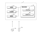
図2は、サーバ1の構成例を示すブロック図である。サーバ1は、制御部11、主記憶部12、通信部13、及び補助記憶部14を備える。
制御部11は、一又は複数のCPU(Central Processing Unit)、MPU(Micro-Processing Unit)、GPU(Graphics Processing Unit)等の演算処理装置を有し、補助記憶部14に記憶されたプログラムPを読み出して実行することにより、種々の情報処理、制御処理等を行う。主記憶部12は、SRAM(Static Random Access Memory)、DRAM(Dynamic Random Access Memory)、フラッシュメモリ等の一時記憶領域であり、制御部11が演算処理を実行するために必要なデータを一時的に記憶する。通信部13は、通信に関する処理を行うための通信モジュールであり、外部と情報の送受信を行う。
2 is a block diagram showing an example of the configuration of the server 1. The server 1 includes a
The
補助記憶部14は、大容量メモリ、ハードディスク等の不揮発性記憶領域であり、制御部11が処理を実行するために必要なプログラムP、その他のデータを記憶している。また、補助記憶部14は、生成モデル50を記憶している。生成モデル50は、上述の如く訓練データを学習済みの機械学習モデルであり、第1医用画像及びデバイス情報を入力として、第2医用画像を生成するモデルである。生成モデル50は、人工知能ソフトウェアを構成するプログラムモジュールとしての利用が想定される。The
なお、補助記憶部14はサーバ1に接続された外部記憶装置であってもよい。また、サーバ1は複数のコンピュータからなるマルチコンピュータであっても良く、ソフトウェアによって仮想的に構築された仮想マシンであってもよい。The
また、本実施の形態においてサーバ1は上記の構成に限られず、例えば操作入力を受け付ける入力部、画像を表示する表示部等を含んでもよい。また、サーバ1は、CD(Compact Disk)、DVD(Digital Versatile Disc)、USB(Universal Serial Bus)メモリ等の可搬型記憶媒体1aを読み取る読取部を備え、可搬型記憶媒体1aからプログラムPを読み取って実行するようにしても良い。あるいはサーバ1は、半導体メモリ1bからプログラムPを読み込んでも良い。In addition, in this embodiment, the server 1 is not limited to the above configuration, and may include, for example, an input unit that accepts operation input, a display unit that displays images, etc. The server 1 may also include a reading unit that reads
図3は、実施の形態1の概要を示す説明図である。図3では、生成モデル50を用いて第1医用画像及びテキスト情報から第2医用画像を生成する様子を概念的に図示している。図3に基づき、本実施の形態の概要を説明する。
Figure 3 is an explanatory diagram showing an overview of the first embodiment. Figure 3 conceptually illustrates how a second medical image is generated from a first medical image and text information using a
生成モデル50は、患者の治療前に画像診断システム2で取得した第1医用画像と、治療に用いる治療用デバイスに関するデバイス情報とを入力として、治療後の状態を予測した第2医用画像を生成する機械学習モデルである。第1医用画像は、血管内画像診断装置21及び透視画像撮影装置22でそれぞれ取得した超音波断層像及びX線透視画像であり、治療前に患者の血管を検査した画像である。The
デバイス情報は、血管内治療に使用するデバイスに関連する情報であり、例えばPCI(Percutaneous Coronary Intervention;経皮的冠動脈形成術)に用いられるステント、バルーン等に関連する情報である。例えばデバイス情報は、患者の血管内に留置するステントの長さ、直径、種類、留置位置、バルーンの種類、バルーンによる拡張後の直径(以下、「拡張径」と呼ぶ)、拡張圧、拡張時間などを含む。なお、治療用デバイスはステント及びバルーンに限定されず、ロータブレータ等の他のデバイスであってもよい。 Device information is information related to devices used in endovascular treatment, such as stents and balloons used in PCI (Percutaneous Coronary Intervention). For example, device information includes the length, diameter, type, and placement position of the stent placed in the patient's blood vessel, the type of balloon, the diameter after expansion by the balloon (hereinafter referred to as the "expansion diameter"), expansion pressure, expansion time, etc. Note that treatment devices are not limited to stents and balloons, and may be other devices such as rotablators.
第2医用画像は、治療用デバイスを用いた治療後の血管内の状態を予測した画像であり、治療後の超音波断層像及びX線透視画像である。なお、サーバ1は超音波断層像及びX線透視画像のいずれか一方のみを第2医用画像として生成してもよく、あるいは3種類以上の画像を生成してもよい。The second medical image is an image that predicts the state inside the blood vessel after treatment using the treatment device, and is an ultrasonic tomographic image and an X-ray fluoroscopic image after treatment. Note that the server 1 may generate only one of the ultrasonic tomographic image and the X-ray fluoroscopic image as the second medical image, or may generate three or more types of images.
サーバ1は、訓練用の第1医用画像及びデバイス情報と、第2医用画像とを含む訓練データを学習し、生成モデル50を生成する。訓練データは、例えば血管内治療を実施済みの患者のデータであり、治療前の超音波断層像及びX線透視画像(第1医用画像)と、当該患者の治療に用いた治療用デバイスに関するデバイス情報と、治療後の超音波断層像及びX線透視画像とを含む。サーバ1は、これらのデータを訓練データに用いて機械学習を行い、生成モデル50を予め生成してある。The server 1 learns training data including a first medical image and device information for training, and a second medical image, and generates a
なお、訓練データは実際の患者のデータに限定されず、例えばGAN(Generative Adversarial Network)等のデータ生成手段で水増しされた仮想のデータであってもよい。 In addition, the training data is not limited to actual patient data, but may be virtual data that has been inflated using a data generation method such as GAN (Generative Adversarial Network).
例えばサーバ1は、患者の治療時に第1医用画像及びデバイス情報を画像診断システム2から取得し、治療後の第2医用画像を生成して表示装置23に表示させる。具体的には、サーバ1は、カテーテル211を用いた超音波検査時に、血管の長手方向に沿って連続してイメージングされた複数の超音波断層像(フレーム画像)を血管内画像診断装置21から順次取得する。また、サーバ1は、超音波検査時に同時に撮影されているX線透視画像を透視画像撮影装置22から取得する。サーバ1は、連続する複数の超音波断層像と、各超音波断層像を取得時のX線透視画像とをデバイス情報と共に生成モデル50に順次入力し、治療後の状態を予測した超音波断層像及びX線透視画像を順次生成する。For example, the server 1 acquires a first medical image and device information from the image
図3の例では、治療後の第2医用画像として、ステントが留置され、バルーンにより拡張された後の血管の超音波断層像及びX線透視画像が生成される様子を図示している。なお、図3では、ステントに対応する部分をハッチングにより図示している。サーバ1は、生成モデル50を用いて治療後の血管の状態を予測し、第2医用画像として提示する。
In the example of Figure 3, an ultrasound tomographic image and an X-ray fluoroscopic image of a blood vessel after a stent has been placed and expanded by a balloon are generated as the second medical image after treatment. Note that in Figure 3, the part corresponding to the stent is shown hatched. The server 1 uses the
なお、本実施の形態では治療時に第2医用画像を生成して画像診断システム2に出力するものとするが、録画された第1医用画像を事後的に生成モデル50に入力して第2医用画像を生成してもよいことは勿論である。In this embodiment, the second medical image is generated during treatment and output to the image
図4は、生成モデル50に関する説明図である。本実施の形態では、生成モデル50としてGANを用いる。GANは、入力データから出力データを生成する生成器(Generator)と、生成器が生成したデータの真偽を識別する識別器(Discriminator)とを備え、生成器及び識別器が競合して学習を行うことでネットワークを構築する。
Figure 4 is an explanatory diagram of the
GANに係る生成器はランダムなノイズ(潜在変数)の入力を受け付け、出力データを生成する。識別器は、学習用に与えられる真のデータと、生成器から与えられるデータとを用いて、生成器から与えられたデータの真偽を学習する。GANでは、最終的に生成器の損失関数が最小化し、かつ、識別器の損失関数が最大化するようにネットワークを構築する。 The generator in a GAN accepts input of random noise (latent variables) and generates output data. The discriminator uses true data provided for learning and data provided by the generator to learn the truth or falsity of the data provided by the generator. In a GAN, a network is constructed so that the loss function of the generator is ultimately minimized and the loss function of the discriminator is maximized.
本実施の形態に係る生成モデル50の生成器は、入力データを潜在変数に変換するエンコーダと、潜在変数から出力データを生成するデコーダとを備え、第1医用画像及びデバイス情報から第2医用画像を生成する。例えば図4に示すように、生成モデル50の生成器は、治療前の超音波断層像、X線透視画像、及びデバイス情報の3種類の入力データの入力を受け付ける3つのエンコーダを備える。また、生成器は、治療後の超音波断層像及びX線透視画像を生成する2つのデコーダを備える。また、生成モデル50は、各デコーダから出力されたデータの真偽を識別する2つの識別器を備える。生成器は、各エンコーダにおいて入力データの特徴量を抽出し、各入力データの特徴量を結合した潜在変数を各デコーダに入力して、治療後の状態を予測した超音波断層像及びX線透視画像を生成する。2つの識別器はそれぞれ、超音波断層像及びX線透視画像の真偽を識別する。The generator of the
サーバ1は、訓練用に与えられる第1医用画像及びデバイス情報と、第2医用画像とを用いて学習を行い、生成モデル50を生成する。例えばサーバ1はまず、生成器のパラメータ(重み等)を固定した上で訓練用の第1医用画像及びデバイス情報を生成器に入力し、第2医用画像を生成する。そしてサーバ1は、生成器が生成した第2医用画像を偽のデータとし、訓練用の第2医用画像を真のデータとして識別器に与え、識別器のパラメータを最適化する。次にサーバ1は、識別器のパラメータを最適値に固定し、生成器の学習を行う。サーバ1は、生成器が生成した第2医用画像を識別器に入力した場合に、真偽の確率が50%に近似するよう生成器のパラメータを最適化する。これにより、サーバ1は生成モデル50を生成する。実際に第1医用画像から第2医用画像を生成する場合は生成器のみを用いる。The server 1 learns using the first medical image and device information given for training and the second medical image to generate a
なお、生成モデル50はGANに限定されず、VAE(Variational Autoencoder)、CNN(例えばU-net)等のニューラルネットワーク、あるいはその他の学習アルゴリズムに基づくモデルであってもよい。
Note that the
また、図4に示す生成モデル50のネットワーク構造は一例であり、本実施の形態はこれに限定されるものではない。例えば、超音波断層像及びX線透視画像という2つの画像を結合して単一の画像とみなし、1種類のエンコーダ及びデコーダで2つの画像を同時に処理可能としてもよい。また、デバイス情報の特徴量を抽出するためのエンコーダは用意せず、One-hotエンコーディング等の手段でデバイス情報(テキストデータ)を符号化し、潜在空間に直接写像(結合)してもよい。このように、生成モデル50のネットワーク構造は種々の変更が考えられる。
The network structure of the
なお、サーバ1は、訓練用の第2医用画像として、図3で例示したように、ステント等のユーザが関心あるオブジェクトを他の画像領域と異なる表示態様で表示する第2医用画像を用いると好適である。例えばサーバ1は、ステント等のオブジェクトに対応する画像領域を、色分け、エッジ強調等によりラベリング(加工)した画像を用いる。これにより、サーバ1は、ユーザが関心あるオブジェクトを識別可能な第2医用画像を生成することができる。It is preferable that the server 1 uses, as the second medical image for training, a second medical image in which an object of interest to the user, such as a stent, is displayed in a different manner from other image regions, as exemplified in FIG. 3. For example, the server 1 uses an image in which an image region corresponding to an object, such as a stent, is labeled (processed) by color coding, edge enhancement, or the like. This allows the server 1 to generate a second medical image in which the object of interest to the user can be identified.
なお、ラベリングされるオブジェクトはステント等の治療用デバイスに限定されず、例えば血管内の病変部(プラーク等)、内腔境界など、その他のオブジェクトであってもよい。In addition, the objects to be labeled are not limited to therapeutic devices such as stents, but may be other objects such as lesions in blood vessels (plaque, etc.) or lumen boundaries.
また、上記では医用画像以外の入力データとしてステント情報を挙げたが、血管内治療に関連するその他の情報も生成モデル50に入力してもよい。例えばサーバ1は、血管内の病変部に関する病変情報を生成モデル50に入力する。病変情報は、例えば病変部の種類(プラーク、石灰化した組織、血管狭窄部など)、位置、性状(病変部の硬さ等)などである。例えばサーバ1は、ステント情報に対応するエンコーダに病変情報を併せて入力し、潜在変数に変換する。これにより、生成モデル50は病変の性質や状態も参照しつつ第2医用画像を生成することができる。
Although stent information has been mentioned above as input data other than medical images, other information related to endovascular treatment may also be input to the
図5は、医用画像の表示画面例を示す説明図である。図5では、表示装置23が表示する画面例であって、第1医用画像及び第2医用画像を表示した画面例を図示している。図5に基づき、血管内治療時に実行される処理フローについて説明する。
Figure 5 is an explanatory diagram showing an example of a display screen for medical images. Figure 5 shows an example of a screen displayed by the
例えば表示装置23は、第1医用画像に対応する現在の血管の超音波断層像及びX線透視画像を、現断層像501、現透視画像502として表示する。また、表示装置23は、デバイス情報の指定入力を受け付けるため、画面左側のメニューバーに指定欄503、503、503…を表示する。また、表示装置23は、現在の治療段階の指定入力を受け付けるためのステータス欄504をメニューバーに表示する。For example, the
表示装置23は、当該画面上でデバイス情報の指定入力を受け付ける。具体的には、表示装置23は、現透視画像502上に矩形枠を描画する操作入力を受け付けることで、治療対象とする血管内の部位(病変部の位置)の指定入力を受け付ける。さらに表示装置23は、ステントの長さ、直径、バルーンによる拡張径等の指定入力を各指定欄503により受け付ける。The
なお、図5の例では、複数の指定欄503により各項目のデバイス情報を個別に入力することとしているが、例えばステントやバルーンの製品名を入力することで、各項目を同時に指定可能としてもよい。In the example of Figure 5, device information for each item is input individually in
また、表示装置23は、ステータス欄504を介して、現在の血管内治療の治療段階の指定入力を受け付ける。サーバ1は、ステータス欄504で指定された治療段階に応じた第2医用画像を生成し、表示装置23に出力する。The
図6は、血管内治療の治療段階に関する説明図である。図6では、PCIを実施する場合の一般的な治療フローを概念的に図示している。一般的には、PCIは以下の手順で実施される。 Figure 6 is an explanatory diagram of the treatment stages of endovascular treatment. Figure 6 conceptually illustrates the general treatment flow when performing PCI. Generally, PCI is performed in the following steps.
まず、カテーテル211を誘導するためのガイドワイヤを患者の血管に挿入する。次に、カテーテル211を挿入して超音波断層像を取得し、X線透視画像と合わせて病変部の状態を確認する。その後、ステントを留置可能なように、必要に応じて留置前にバルーンによる血管の拡張が行われる。なお、ステント留置前のバルーン拡張は省略され得る。First, a guide wire for guiding the
次に、ステントを血管内に留置し、バルーンによって病変部を拡張する。ステントの留置後、超音波画像を再度取得し、X線透視画像と合わせて拡張後の病変部の状態を確認する。その後、ステントの拡張が不十分である場合などには、再びバルーンによる血管の拡張が行われる。なお、ステント留置後のバルーン拡張は省略され得る。最後に病変部の状態を各画像で確認し、一連の処置が終了する。Next, a stent is placed in the blood vessel and the affected area is expanded using a balloon. After the stent is placed, ultrasound images are taken again and the condition of the affected area after expansion is confirmed in conjunction with the X-ray fluoroscopy images. If the stent is not sufficiently expanded, the blood vessel is expanded again using a balloon. Note that balloon expansion after stent placement may be omitted. Finally, the condition of the affected area is confirmed using each image, and the series of procedures is completed.
なお、以下の説明では簡潔のため、ステント留置前のバルーン拡張を「前拡張」と呼び、ステント留置後のバルーン拡張を「後拡張」と呼ぶ。For simplicity, in the following explanation, balloon expansion before stent placement will be referred to as "pre-dilation," and balloon expansion after stent placement will be referred to as "post-dilation."
本実施の形態においてサーバ1は、上記の前拡張、ステントの拡張、及び後拡張に合わせて、各治療段階の処置前の第1医用画像から処置後の第2医用画像を生成モデル50により生成する。In this embodiment, the server 1 generates a second medical image after treatment from a first medical image before treatment at each treatment stage using a
例えばサーバ1は、ConditionalGANのように、生成モデル50を入力データのクラスラベルを入力可能なモデルとして構成する。サーバ1は、生成モデル50に第1医用画像を入力する際に、第1医用画像のクラスを示すラベルデータとして、前拡張の処置前であるか、ステントの拡張前であるか、又は後拡張の処置前であるかを示す値を入力する。そしてサーバ1は、入力されたラベルデータに応じて、いずれかの処置後の第2医用画像を生成する。これにより、ユーザはこれから行う処置後の状態を予測した第2医用画像を段階的に確認することができる。For example, the server 1 configures the
図5では、ステント拡張時の表示画面例を図示している。サーバ1は、ステータス欄504で指定された治療段階に従い、ステント拡張後の第2医用画像を生成する。すなわち、サーバ1は、ステント拡張前に血管内画像診断装置21で生成された超音波断層像と、透視画像撮影装置22で撮影されたX線透視画像と、ユーザが指定したデバイス情報とを生成モデル50に入力し、ステント拡張後の状態を予測した超音波断層像及びX線透視画像を生成する。この場合、例えばサーバ1は、ステントに対応する画像領域を他の領域と異なる表示態様で示す超音波断層像及びX線透視画像を第2医用画像として生成する。
Figure 5 illustrates an example of a display screen during stent expansion. The server 1 generates a second medical image after stent expansion according to the treatment stage specified in the
サーバ1は、生成した第2医用画像を出力し、表示装置23に表示させる。表示装置23は、第2医用画像に対応する超音波断層像及びX線透視画像を、予測断層像505、予測透視画像506として表示する。The server 1 outputs the generated second medical image and displays it on the
なお、図5では第2医用画像として2次元の超音波断層像及びX線透視画像を図示しているが、サーバ1は2次元の超音波断層像及びX線透視画像を再構成し、3次元の血管画像を生成して表示装置23に表示させてもよい。図3で説明したように、サーバ1は、血管内画像診断装置21から順次取得する複数の超音波断層像(横断層像)と、X線透視画像とを生成モデル50に順次入力して、治療後の状態を予測した複数の超音波断層像と、X線透視画像とを第2医用画像として生成する。サーバ1は、超音波検査時にX線不透過マーカ等の手段で検出したカテーテル211の位置に応じて各超音波断層像とX線透視画像との位置合わせを行い、公知の手法で3次元画像に変換する。これにより、治療後の血管内の状態を3次元で表現し、ユーザに提示することができる。
In addition, although FIG. 5 illustrates two-dimensional ultrasound tomographic images and X-ray fluoroscopic images as the second medical images, the server 1 may reconstruct the two-dimensional ultrasound tomographic images and X-ray fluoroscopic images to generate three-dimensional vascular images and display them on the
また、図5の例では、一パターンのデバイス情報の指定入力を受け付けて一パターンの第2医用画像を表示するものとしたが、複数パターンのデバイス情報の指定入力を受け付けて、複数パターンに対応する複数の第2医用画像を表示してもよい。例えばサーバ1は、治療に用いるステントの候補として複数のステントの指定入力を受け付け、各ステントを用いた場合の第2医用画像を別々に生成し、表示装置23にプレビュー表示させる。これにより、ユーザの利便性を向上させることができる。
In the example of FIG. 5, one pattern of device information is accepted and one pattern of second medical image is displayed, but multiple patterns of device information may be accepted and multiple second medical images corresponding to the multiple patterns may be displayed. For example, the server 1 accepts the input of multiple stents as candidates for stents to be used in treatment, generates second medical images for each stent separately, and displays them as previews on the
図7は、生成モデル50の生成処理の手順を示すフローチャートである。図7に基づき、機械学習により生成モデル50を生成する際の処理内容について説明する。
サーバ1の制御部11は、治療を実施済みの患者についてのデータであって、治療前の医用画像である第1医用画像、及び治療に用いた治療用デバイスに関するデバイス情報と、治療後の医用画像である第2医用画像とを含む訓練データを取得する(ステップS11)。具体的には、制御部11は、血管内治療を実施済みの患者に関し、治療前の超音波断層像及びX線透視画像を第1医用画像として取得する。また、制御部11は、血管内治療に用いたステント、バルーン等の情報をデバイス情報として取得する。また、制御部11は、血管内治療後の超音波断層像及びX線透視画像を第2医用画像として取得する。
7 is a flowchart showing the procedure of the generation process of the
The
制御部11は訓練データに基づき、第1医用画像及びデバイス情報を入力した場合に第2医用画像を生成する生成モデル50を生成する(ステップS12)。具体的には、制御部11は、治療前の超音波断層像、X線透視画像、及びデバイス情報を入力として、治療後の超音波断層像及びX線透視画像を出力とするGANを生成する。制御部11は一連の処理を終了する。Based on the training data, the
図8は、第2医用画像の生成処理の手順を示すフローチャートである。図8に基づき、第2医用画像を生成する際の処理内容について説明する。
サーバ1の制御部11は、患者の管腔器官の治療に用いる治療用デバイスに関するデバイス情報を画像診断システム2から取得する(ステップS31)。また、制御部11は、第1医用画像を画像診断システム2から取得する(ステップS32)。具体的には上述の如く、制御部11は、治療対象の患者を検査した超音波断層像と、超音波検査時に同時に撮影されたX線透視画像とを取得する。
8 is a flowchart showing the procedure of the generation process of the second medical image. The process contents when the second medical image is generated will be described with reference to FIG.
The
制御部11は、ユーザからの操作入力に応じて、ステント留置前の前拡張が必要か否かを判定する(ステップS33)。前拡張が必要ではないと判定した場合(S33:NO)、制御部11は処理をステップS36に移行する。前拡張が必要であると判定した場合(S33:YES)、制御部11は、ステップS32で取得した第1医用画像を生成モデル50に入力して、前拡張後の第2医用画像を生成し、表示装置23に出力する(ステップS34)。The
制御部11は、ユーザからの操作入力に応じて、前拡張が完了したか否かを判定する(ステップS35)。前拡張が完了していないと判定した場合(S35:NO)、制御部11は処理を待機する。The
前拡張が完了したと判定した場合(S35:YES)、制御部11はステント拡張後の第2医用画像を生成し、表示装置23に出力する(ステップS36)。If it is determined that pre-expansion is completed (S35: YES), the
制御部11は、ユーザからの操作入力に応じて、後拡張が必要であるか否かを判定する(ステップS37)。後拡張が必要でないと判定した場合(S37:NO)、制御部11は一連の処理を終了する。後拡張が必要であると判定した場合(S37:YES)、制御部11は、第1医用画像を再取得する(ステップS38)。制御部11は、取得した第1医用画像を生成モデル50に入力して後拡張後の第2医用画像を生成し、表示装置23に出力する(ステップS39)。制御部11は一連の処理を終了する。The
以上より、本実施の形態1によれば、治療前の第1医用画像から治療後の状態を予測した第2医用画像を生成し、ユーザに提示することができる。 As described above, according to this embodiment 1, a second medical image that predicts the post-treatment condition can be generated from a first medical image taken before treatment and presented to the user.
また、本実施の形態1によれば、複数の治療段階に合わせて、各処置後の第2医用画像を提示することができる。 Furthermore, according to this embodiment 1, a second medical image after each treatment can be presented in accordance with multiple treatment stages.
また、本実施の形態1によれば、血管内治療に合わせて、前拡張後、ステント拡張後、及び後拡張後それぞれの第2医用画像を生成してユーザに提示することができる。 Furthermore, according to this embodiment 1, second medical images can be generated and presented to the user after pre-expansion, after stent expansion, and after post-expansion in accordance with endovascular treatment.
また、本実施の形態1によれば、X線透視画像上で対象部位の指定入力を受け付けることで、デバイス情報を好適に指定することができる。 Furthermore, according to this embodiment 1, device information can be appropriately specified by accepting input specifying the target area on the X-ray fluoroscopic image.
また、本実施の形態1によれば、生成モデル50を用いて順次生成される複数の超音波断層像(横断層像)と、X線透視画像とから、治療後の状態を3次元で表現した画像を提供することもできる。
In addition, according to this embodiment 1, it is also possible to provide an image that represents the post-treatment condition in three dimensions from multiple ultrasound tomographic images (transverse images) generated sequentially using the
また、本実施の形態1によれば、デバイス情報以外にも病変情報を生成モデル50の入力に用いることで、第2医用画像の生成精度を高めることができる。
Furthermore, according to this embodiment 1, by using lesion information in addition to device information as input to the
(実施の形態2)
本実施の形態では、第1医用画像及び第2医用画像として超音波断層像のみを扱う形態について述べる。なお、実施の形態1と重複する内容については同一の符号を付して説明を省略する。
(Embodiment 2)
In this embodiment, a form will be described in which only ultrasonic tomographic images are used as the first medical image and the second medical image. Note that the same reference numerals are used to denote the same contents as in the first embodiment, and the description thereof will be omitted.
図9は、実施の形態2に係る生成モデル50に関する説明図である。本実施の形態に係る生成モデル50は、X線透視画像を処理するためのエンコーダ及びデコーダを備えず、治療前の超音波断層像及びデバイス情報それぞれの入力を受け付ける2つのエンコーダ、治療後の超音波断層像を生成するデコーダ、及びデコーダが生成した超音波断層像の真偽を識別する識別器のみを有する。サーバ1は、訓練用の第1医用画像及び第2医用画像として、血管内治療を実施済みの患者の治療前後の超音波断層像を訓練データとして用い、図9に示す生成モデル50を生成する。
Figure 9 is an explanatory diagram of a
図10は、実施の形態2に係る医用画像の表示画面例を示す説明図である。本実施の形態において表示装置23は、実施の形態1と同様に、第1医用画像に対応する現断層像501を表示する。本実施の形態ではさらに、表示装置23は、複数の超音波断層像(横断層像)を再構成した縦断層像521を表示する。
Figure 10 is an explanatory diagram showing an example of a display screen of a medical image according to
縦断層像521は、血管内画像診断装置21で連続してイメージングされた複数の横断層像を、血管の長手方向に沿う形で再構成した縦断面画像である。サーバ1は、カテーテル211の走査に従い、血管の長手方向に沿って連続してイメージングされた複数の横断層像(フレーム画像)から縦断層像521を再構成し、表示装置23に表示させる。本実施の形態で表示装置23は、縦断層像521上で矩形枠の描画入力を受け付けることで、治療対象とする血管内の部位の指定入力を受け付ける。そのほか、表示装置23は実施の形態1と同様に、指定欄503により他のデバイス情報の指定入力を受け付ける。The longitudinal
サーバ1は、第1医用画像に対応する超音波断層像と、デバイス情報とを生成モデル50に入力し、第2医用画像に対応する超音波断層像を生成する。そしてサーバ1は、生成した超音波断層像を予測断層像505として表示させる。なお、予測断層像505として、横断層像だけでなく縦断層像を表示してもよいことは勿論である。The server 1 inputs an ultrasonic tomographic image corresponding to the first medical image and device information into the
なお、実施の形態1と同様に、生成モデル50で順次生成する複数の超音波断層像を再構成し、3次元画像を生成して表示装置23に表示させてもよい。
As in embodiment 1, multiple ultrasonic tomographic images generated sequentially by the
上記の点以外は実施の形態1と同様であるため、本実施の形態ではフローチャートその他の詳細な説明は省略する。 Other than the above, the present embodiment is the same as embodiment 1, so detailed explanations of the flowchart and other aspects will be omitted.
(実施の形態3)
本実施の形態では、生成モデル50が生成した第2医用画像の修正情報の入力を受け付け、入力された修正情報に基づいて再学習を行う形態について説明する。
(Embodiment 3)
In this embodiment, a form will be described in which the
例えば表示装置23は、図5で例示した表示画面上で、生成モデル50により生成した第2医用画像を修正するための修正情報の入力をユーザから受け付ける。具体的には、表示装置23は、色分け表示したステント(治療用デバイス)の位置、長さ、直径(幅)等を修正する修正入力を受け付ける。例えば表示装置23は、予測断層像505又は予測透視画像506に対し、ステントに対応する画像領域の境界(エッジ)を新たに描画する描画入力を受け付ける。表示装置23は、ユーザによりステントに対応する画像領域が描画された第2医用画像を修正情報としてサーバ1に送信し、再学習を行わせる。For example, the
なお、本実施の形態ではステント拡張後の第2医用画像に対する修正情報の入力を受け付けることとするが、前拡張後、又は後拡張後の第2医用画像に対する修正情報の入力を受け付けてもよい。In this embodiment, the input of correction information for the second medical image after stent expansion is accepted, but the input of correction information for the second medical image after pre-expansion or post-expansion may also be accepted.
サーバ1は、表示装置23から取得した修正情報に基づいて再学習を行い、生成モデル50を更新する。具体的には、サーバ1は、再学習用の訓練データとして、第2医用画像を生成した際に入力とした第1医用画像及びデバイス情報と、ステントの画像領域が描画された第2医用画像とを生成モデル50に与え、生成器及び識別器のパラメータを更新する。The server 1 performs re-learning based on the correction information acquired from the
図11は、実施の形態3に係る第2医用画像の生成処理の手順を示すフローチャートである。ステント留置後の第2医用画像を生成して表示装置23に出力した後(ステップS36)、サーバ1は以下の処理を実行する。
サーバ1の制御部11は、出力した第2医用画像の修正情報の入力を受け付ける(ステップS201)。例えば制御部11は、第2医用画像上でステントの位置、長さ、直径等を修正する修正入力を受け付ける。制御部11は、処理をステップS37に移行する。
11 is a flowchart showing the procedure of the generation process of the second medical image according to embodiment 3. After the second medical image after the stent placement is generated and output to the display device 23 (step S36), the server 1 executes the following process.
The
ステップS37でNO、又はステップS39の処理を実行後、制御部11は、ステップS201で入力された修正情報に基づいて生成モデル50を更新する(ステップS202)。具体的には、制御部11は、ステップS36で第2医用画像を生成した際に入力とした第1医用画像及びデバイス情報を訓練用の入力データとし、ステップS36で生成した第2医用画像を修正した画像を訓練用の出力データとして再学習を行い、生成器及び識別器のパラメータを更新する。制御部11は一連の処理を終了する。
After step S37 is NO or the processing of step S39 is executed, the
以上より、本実施の形態3によれば、本システムの運用を通じて第2医用画像の生成精度を高めることができる。 As described above, according to this embodiment 3, the accuracy of generating the second medical image can be improved through the operation of this system.
今回開示された実施の形態はすべての点で例示であって、制限的なものではないと考えられるべきである。本発明の範囲は、上記した意味ではなく、請求の範囲によって示され、請求の範囲と均等の意味及び範囲内でのすべての変更が含まれることが意図される。The embodiments disclosed herein are illustrative in all respects and should not be considered limiting. The scope of the present invention is indicated by the claims, not by the above meaning, and is intended to include all modifications within the meaning and scope of the claims.
1 サーバ(情報処理装置)
1a 可搬型記憶媒体
1b 半導体メモリ
11 制御部
12 主記憶部
13 通信部
14 補助記憶部
N ネットワーク
P プログラム
2 画像診断システム
21 血管内画像診断装置
211 カテーテル
22 透視画像撮影装置
221 X線源
222 X線センサ
23 表示装置
501 現断層像
502 現透視画像
503 指定欄
504 ステータス欄
505 予測断層像
506 予測透視画像
521 縦断層像
1 Server (information processing device)
REFERENCE SIGNS
Claims (12)
前記第1医用画像及びデバイス情報と、該第1医用画像に対応する前記治療段階を表すクラスラベルとを入力した場合に、該治療段階の処置後の第2医用画像を生成するよう学習済みのモデルに、取得した前記第1医用画像及びデバイス情報と、前記クラスラベルとを入力して前記第2医用画像を生成する
処理をコンピュータに実行させるプログラム。 Acquiring a first medical image of a patient's luminal organ before any of a plurality of treatment steps and device information related to a treatment device used to treat the luminal organ;
A program that causes a computer to execute a process of inputting the acquired first medical image and device information and the class label into a model that has been trained to generate a second medical image after treatment at a treatment stage when the first medical image, device information , and a class label that represents the treatment stage corresponding to the first medical image are input, and generating the second medical image.
ステント留置前のバルーン拡張、前記ステントの拡張、及び前記ステント留置後のバルーン拡張のいずれかの治療段階の処置前の第1医用画像を取得して前記第2医用画像を生成する
請求項1に記載のプログラム。 The treatment is an intravascular treatment using a catheter,
The program according to claim 1 , further comprising acquiring a first medical image before treatment at any one of the treatment stages of balloon expansion before stent placement, expansion of the stent, and balloon expansion after stent placement, and generating the second medical image.
前記第1医用画像に対し、治療対象の前記管腔器官内の部位と、該部位の治療に用いる複数パターンの前記治療用デバイスとを指定する指定入力を受け付け、receiving a designation input for designating a region in the hollow organ to be treated and a plurality of patterns of the treatment device to be used for treating the region in the hollow organ for the first medical image;
指定された前記部位及び複数パターンの治療用デバイスを示す前記デバイス情報を前記モデルに入力することで、複数パターンに対応する複数の前記第2医用画像を生成するThe device information indicating the specified region and a plurality of patterns of treatment devices is input to the model, thereby generating a plurality of the second medical images corresponding to the plurality of patterns.
請求項1又は2に記載のプログラム。3. The program according to claim 1 or 2.
前記透視画像を表示部に表示し、
前記透視画像に対し、治療対象の前記管腔器官内の部位と、該部位の治療に用いる前記治療用デバイスとを指定する指定入力を受け付け、
指定された前記部位及び治療用デバイスを示す前記デバイス情報を前記モデルに入力する
請求項1~3のいずれか1項に記載のプログラム。 the first medical image includes a fluoroscopic image of the inside of the patient's body;
Displaying the fluoroscopic image on a display unit;
receiving a designation input for designating a region in the hollow organ to be treated and the treatment device to be used for treating the region on the fluoroscopic image;
The program according to any one of claims 1 to 3, further comprising inputting the device information indicating the designated region and treatment device into the model.
前記管腔器官の長手方向に沿って連続してイメージングされた複数の横断層像から縦断層像を生成して表示部に表示し、
前記縦断層像に対し、治療対象の前記管腔器官内の部位と、該部位の治療に用いる前記治療用デバイスとを指定する指定入力を受け付け、
指定された前記部位及び治療用デバイスを示す前記デバイス情報を前記モデルに入力する
請求項1~3のいずれか1項に記載のプログラム。 The first medical image includes a cross-sectional image of the inside of the hollow organ,
generating a longitudinal tomographic image from a plurality of transverse tomographic images successively imaged along the longitudinal direction of the tubular organ and displaying the longitudinal tomographic image on a display unit;
receiving a designation input for designating a region in the hollow organ to be treated and the treatment device to be used for treating the region on the longitudinal tomographic image;
The program according to any one of claims 1 to 3, further comprising inputting the device information indicating the designated region and treatment device into the model.
生成した治療後の複数の横断層像から3次元の前記第2医用画像を生成する
請求項5に記載のプログラム。 inputting the plurality of transverse slice images into the model to generate a plurality of post-treatment transverse slice images;
The program according to claim 5 , further comprising: generating the second three-dimensional medical image from the generated multiple cross-sectional images after treatment.
前記病変情報を前記モデルに入力して前記第2医用画像を生成する
請求項1~6のいずれか1項に記載のプログラム。 Accepting input of lesion information indicating the characteristics of a lesion in the tubular organ;
The program according to any one of claims 1 to 6, further comprising inputting the lesion information into the model to generate the second medical image.
前記修正情報に基づき、前記モデルを更新する
請求項1~7のいずれか1項に記載のプログラム。 Accepting input of correction information for the generated second medical image;
The program according to any one of claims 1 to 7, further comprising updating the model based on the correction information.
請求項1~8のいずれか1項に記載のプログラム。The program according to any one of claims 1 to 8.
前記第1医用画像及びデバイス情報と、該第1医用画像に対応する前記治療段階を表すクラスラベルとを入力した場合に、該治療段階の処置後の第2医用画像を生成するよう学習済みのモデルに、取得した前記第1医用画像及びデバイス情報と、前記クラスラベルとを入力して前記第2医用画像を生成する
処理をコンピュータが実行する情報処理方法。 Acquiring a first medical image of a patient's luminal organ before any of a plurality of treatment steps and device information related to a treatment device used to treat the luminal organ;
An information processing method in which a computer executes a process of inputting the acquired first medical image and device information and the class label into a model that has been trained to generate a second medical image after treatment at a treatment stage when the first medical image, device information , and a class label representing the treatment stage corresponding to the first medical image are input, and generating the second medical image.
前記第1医用画像及びデバイス情報と、該第1医用画像に対応する前記治療段階を表すクラスラベルとを入力した場合に、該治療段階の処置後の第2医用画像を生成するよう学習済みのモデルに、取得した前記第1医用画像及びデバイス情報と、前記クラスラベルとを入力して前記第2医用画像を生成する生成部と
を備える情報処理装置。 1. An information processing device comprising: an acquisition unit that acquires a first medical image of a patient's tubular organ before treatment at any one of a plurality of treatment stages , and device information related to a therapeutic device used to treat the tubular organ; and a generation unit that inputs the acquired first medical image and device information , and a class label representing the treatment stage corresponding to the first medical image , into a model that has been trained to generate a second medical image after treatment at the treatment stage , and generates the second medical image.
前記訓練データに基づき、前記第1医用画像及びデバイス情報と、該第1医用画像に対応する前記治療段階を表すクラスラベルとを入力した場合に前記第2医用画像を生成する学習済みモデルを生成する
処理をコンピュータが実行するモデル生成方法。 Obtaining training data including a first medical image of a patient's luminal organ before each of a plurality of treatment steps , a second medical image of the patient's luminal organ after each of a plurality of treatment steps , and device information related to a treatment device used to treat the luminal organ;
A model generation method in which a computer executes a process of generating a trained model that generates the second medical image when the first medical image and device information , and a class label representing the treatment stage corresponding to the first medical image are input based on the training data.
Applications Claiming Priority (3)
| Application Number | Priority Date | Filing Date | Title |
|---|---|---|---|
| JP2020058996 | 2020-03-27 | ||
| JP2020058996 | 2020-03-27 | ||
| PCT/JP2021/009301 WO2021193021A1 (en) | 2020-03-27 | 2021-03-09 | Program, information processing method, information processing device, and model generation method |
Publications (2)
| Publication Number | Publication Date |
|---|---|
| JPWO2021193021A1 JPWO2021193021A1 (en) | 2021-09-30 |
| JP7607635B2 true JP7607635B2 (en) | 2024-12-27 |
Family
ID=77891479
Family Applications (1)
| Application Number | Title | Priority Date | Filing Date |
|---|---|---|---|
| JP2022509536A Active JP7607635B2 (en) | 2020-03-27 | 2021-03-09 | PROGRAM, INFORMATION PROCESSING METHOD, INFORMATION PROCESSING APPARATUS AND MODEL GENERATION METHOD |
Country Status (2)
| Country | Link |
|---|---|
| JP (1) | JP7607635B2 (en) |
| WO (1) | WO2021193021A1 (en) |
Families Citing this family (1)
| Publication number | Priority date | Publication date | Assignee | Title |
|---|---|---|---|---|
| WO2024224910A1 (en) * | 2023-04-28 | 2024-10-31 | ソニーグループ株式会社 | Learning model generation method, presentation method, evaluation method, and generation method |
Citations (4)
| Publication number | Priority date | Publication date | Assignee | Title |
|---|---|---|---|---|
| JP2018525074A (en) | 2015-07-08 | 2018-09-06 | アオーティカ コーポレイション | Apparatus and method for anatomical mapping for prosthetic implants |
| WO2019002526A1 (en) | 2017-06-29 | 2019-01-03 | Koninklijke Philips N.V. | Device and method for predicting an unfolded state of a foldable implant in biological tissue |
| JP2019510547A (en) | 2016-02-16 | 2019-04-18 | メンティス アー・ベーMentice AB | System and method for routing a catheter-like conduit line in a vessel |
| JP2020503909A (en) | 2016-09-28 | 2020-02-06 | ライトラボ・イメージング・インコーポレーテッド | Method of using a stent planning system and vascular representation |
-
2021
- 2021-03-09 WO PCT/JP2021/009301 patent/WO2021193021A1/en not_active Ceased
- 2021-03-09 JP JP2022509536A patent/JP7607635B2/en active Active
Patent Citations (4)
| Publication number | Priority date | Publication date | Assignee | Title |
|---|---|---|---|---|
| JP2018525074A (en) | 2015-07-08 | 2018-09-06 | アオーティカ コーポレイション | Apparatus and method for anatomical mapping for prosthetic implants |
| JP2019510547A (en) | 2016-02-16 | 2019-04-18 | メンティス アー・ベーMentice AB | System and method for routing a catheter-like conduit line in a vessel |
| JP2020503909A (en) | 2016-09-28 | 2020-02-06 | ライトラボ・イメージング・インコーポレーテッド | Method of using a stent planning system and vascular representation |
| WO2019002526A1 (en) | 2017-06-29 | 2019-01-03 | Koninklijke Philips N.V. | Device and method for predicting an unfolded state of a foldable implant in biological tissue |
Also Published As
| Publication number | Publication date |
|---|---|
| WO2021193021A1 (en) | 2021-09-30 |
| JPWO2021193021A1 (en) | 2021-09-30 |
Similar Documents
| Publication | Publication Date | Title |
|---|---|---|
| US12254677B2 (en) | System and methods for augmenting X-ray images for training of deep neural networks | |
| US12357189B2 (en) | Method and device for operating a medical imaging device for the positionally correct representation of non-anatomical structures during an imaging examination | |
| JP7490045B2 (en) | PROGRAM, INFORMATION PROCESSING METHOD, INFORMATION PROCESSING APPARATUS AND MODEL GENERATION METHOD | |
| JP7696356B2 (en) | Information processing device, information processing method, and program | |
| JP7695262B2 (en) | Information processing device, information processing method, program, and model generation method | |
| CN112309574A (en) | Method and apparatus for deformation simulation | |
| JP7536861B2 (en) | PROGRAM, INFORMATION PROCESSING METHOD, INFORMATION PROCESSING APPARATUS AND MODEL GENERATION METHOD | |
| JP7536862B2 (en) | PROGRAM, INFORMATION PROCESSING METHOD, INFORMATION PROCESSING APPARATUS AND MODEL GENERATION METHOD | |
| JP7607635B2 (en) | PROGRAM, INFORMATION PROCESSING METHOD, INFORMATION PROCESSING APPARATUS AND MODEL GENERATION METHOD | |
| JP7803928B2 (en) | Program, image processing method and image processing device | |
| JP7737357B2 (en) | Program, information processing method, and information processing system | |
| JP7581331B2 (en) | Program, information processing method, learning model generation method, learning model re-learning method, and information processing system | |
| JP7667134B2 (en) | PROGRAM, INFORMATION PROCESSING METHOD, INFORMATION PROCESSING APPARATUS AND MODEL GENERATION METHOD | |
| WO2021199966A1 (en) | Program, information processing method, training model generation method, retraining method for training model, and information processing system | |
| WO2021193026A1 (en) | Program, information processing method, information processing device, and model generation method | |
| CN113539516B (en) | Method and device for obtaining post-application effect of treatment scheme | |
| JP2024018562A (en) | Image processing device, method and program | |
| JP2023130134A (en) | Program, information processing method, and information processing device | |
| EP4623833A1 (en) | Providing feedback during balloon angioplasty | |
| JP7545466B2 (en) | PROGRAM, INFORMATION PROCESSING METHOD, INFORMATION PROCESSING APPARATUS AND MODEL GENERATION METHOD | |
| JP2022142607A (en) | Program, image processing method, image processing apparatus, and model generation method | |
| JP7597626B2 (en) | PROGRAM, IMAGE PROCESSING METHOD, IMAGE PROCESSING APPARATUS AND MODEL GENERATION METHOD | |
| JP2024139509A (en) | PROGRAM, IMAGE PROCESSING METHOD, IMAGE PROCESSING APPARATUS AND MODEL GENERATION METHOD | |
| US20250191241A1 (en) | Method for representing at least one medical instrument in a hollow organ, data processing apparatus, imaging system, and computer program product | |
| EP4625434A1 (en) | Supporting an interventional procedure |
Legal Events
| Date | Code | Title | Description |
|---|---|---|---|
| A621 | Written request for application examination |
Free format text: JAPANESE INTERMEDIATE CODE: A621 Effective date: 20231013 |
|
| A131 | Notification of reasons for refusal |
Free format text: JAPANESE INTERMEDIATE CODE: A131 Effective date: 20240723 |
|
| A521 | Request for written amendment filed |
Free format text: JAPANESE INTERMEDIATE CODE: A523 Effective date: 20240917 |
|
| TRDD | Decision of grant or rejection written | ||
| A01 | Written decision to grant a patent or to grant a registration (utility model) |
Free format text: JAPANESE INTERMEDIATE CODE: A01 Effective date: 20241203 |
|
| A61 | First payment of annual fees (during grant procedure) |
Free format text: JAPANESE INTERMEDIATE CODE: A61 Effective date: 20241217 |
|
| R150 | Certificate of patent or registration of utility model |
Ref document number: 7607635 Country of ref document: JP Free format text: JAPANESE INTERMEDIATE CODE: R150 |