JP7581331B2 - Program, information processing method, learning model generation method, learning model re-learning method, and information processing system - Google Patents
Program, information processing method, learning model generation method, learning model re-learning method, and information processing system Download PDFInfo
- Publication number
- JP7581331B2 JP7581331B2 JP2022511733A JP2022511733A JP7581331B2 JP 7581331 B2 JP7581331 B2 JP 7581331B2 JP 2022511733 A JP2022511733 A JP 2022511733A JP 2022511733 A JP2022511733 A JP 2022511733A JP 7581331 B2 JP7581331 B2 JP 7581331B2
- Authority
- JP
- Japan
- Prior art keywords
- tomographic image
- image
- model
- objects
- hollow organ
- Prior art date
- Legal status (The legal status is an assumption and is not a legal conclusion. Google has not performed a legal analysis and makes no representation as to the accuracy of the status listed.)
- Active
Links
Images


Classifications
-
- G—PHYSICS
- G06—COMPUTING OR CALCULATING; COUNTING
- G06V—IMAGE OR VIDEO RECOGNITION OR UNDERSTANDING
- G06V10/00—Arrangements for image or video recognition or understanding
- G06V10/70—Arrangements for image or video recognition or understanding using pattern recognition or machine learning
- G06V10/77—Processing image or video features in feature spaces; using data integration or data reduction, e.g. principal component analysis [PCA] or independent component analysis [ICA] or self-organising maps [SOM]; Blind source separation
- G06V10/774—Generating sets of training patterns; Bootstrap methods, e.g. bagging or boosting
-
- A—HUMAN NECESSITIES
- A61—MEDICAL OR VETERINARY SCIENCE; HYGIENE
- A61B—DIAGNOSIS; SURGERY; IDENTIFICATION
- A61B8/00—Diagnosis using ultrasonic, sonic or infrasonic waves
- A61B8/12—Diagnosis using ultrasonic, sonic or infrasonic waves in body cavities or body tracts, e.g. by using catheters
-
- A—HUMAN NECESSITIES
- A61—MEDICAL OR VETERINARY SCIENCE; HYGIENE
- A61B—DIAGNOSIS; SURGERY; IDENTIFICATION
- A61B8/00—Diagnosis using ultrasonic, sonic or infrasonic waves
- A61B8/08—Clinical applications
- A61B8/0891—Clinical applications for diagnosis of blood vessels
-
- A—HUMAN NECESSITIES
- A61—MEDICAL OR VETERINARY SCIENCE; HYGIENE
- A61B—DIAGNOSIS; SURGERY; IDENTIFICATION
- A61B8/00—Diagnosis using ultrasonic, sonic or infrasonic waves
- A61B8/52—Devices using data or image processing specially adapted for diagnosis using ultrasonic, sonic or infrasonic waves
- A61B8/5215—Devices using data or image processing specially adapted for diagnosis using ultrasonic, sonic or infrasonic waves involving processing of medical diagnostic data
- A61B8/5223—Devices using data or image processing specially adapted for diagnosis using ultrasonic, sonic or infrasonic waves involving processing of medical diagnostic data for extracting a diagnostic or physiological parameter from medical diagnostic data
-
- G—PHYSICS
- G06—COMPUTING OR CALCULATING; COUNTING
- G06T—IMAGE DATA PROCESSING OR GENERATION, IN GENERAL
- G06T7/00—Image analysis
- G06T7/0002—Inspection of images, e.g. flaw detection
- G06T7/0012—Biomedical image inspection
-
- G—PHYSICS
- G06—COMPUTING OR CALCULATING; COUNTING
- G06T—IMAGE DATA PROCESSING OR GENERATION, IN GENERAL
- G06T7/00—Image analysis
- G06T7/10—Segmentation; Edge detection
- G06T7/11—Region-based segmentation
-
- G—PHYSICS
- G06—COMPUTING OR CALCULATING; COUNTING
- G06T—IMAGE DATA PROCESSING OR GENERATION, IN GENERAL
- G06T7/00—Image analysis
- G06T7/60—Analysis of geometric attributes
- G06T7/62—Analysis of geometric attributes of area, perimeter, diameter or volume
-
- G—PHYSICS
- G06—COMPUTING OR CALCULATING; COUNTING
- G06V—IMAGE OR VIDEO RECOGNITION OR UNDERSTANDING
- G06V10/00—Arrangements for image or video recognition or understanding
- G06V10/70—Arrangements for image or video recognition or understanding using pattern recognition or machine learning
- G06V10/764—Arrangements for image or video recognition or understanding using pattern recognition or machine learning using classification, e.g. of video objects
-
- G—PHYSICS
- G06—COMPUTING OR CALCULATING; COUNTING
- G06V—IMAGE OR VIDEO RECOGNITION OR UNDERSTANDING
- G06V10/00—Arrangements for image or video recognition or understanding
- G06V10/70—Arrangements for image or video recognition or understanding using pattern recognition or machine learning
- G06V10/77—Processing image or video features in feature spaces; using data integration or data reduction, e.g. principal component analysis [PCA] or independent component analysis [ICA] or self-organising maps [SOM]; Blind source separation
- G06V10/776—Validation; Performance evaluation
-
- G—PHYSICS
- G06—COMPUTING OR CALCULATING; COUNTING
- G06V—IMAGE OR VIDEO RECOGNITION OR UNDERSTANDING
- G06V10/00—Arrangements for image or video recognition or understanding
- G06V10/70—Arrangements for image or video recognition or understanding using pattern recognition or machine learning
- G06V10/77—Processing image or video features in feature spaces; using data integration or data reduction, e.g. principal component analysis [PCA] or independent component analysis [ICA] or self-organising maps [SOM]; Blind source separation
- G06V10/778—Active pattern-learning, e.g. online learning of image or video features
-
- A—HUMAN NECESSITIES
- A61—MEDICAL OR VETERINARY SCIENCE; HYGIENE
- A61B—DIAGNOSIS; SURGERY; IDENTIFICATION
- A61B8/00—Diagnosis using ultrasonic, sonic or infrasonic waves
- A61B8/13—Tomography
- A61B8/14—Echo-tomography
-
- G—PHYSICS
- G06—COMPUTING OR CALCULATING; COUNTING
- G06T—IMAGE DATA PROCESSING OR GENERATION, IN GENERAL
- G06T2200/00—Indexing scheme for image data processing or generation, in general
- G06T2200/24—Indexing scheme for image data processing or generation, in general involving graphical user interfaces [GUIs]
-
- G—PHYSICS
- G06—COMPUTING OR CALCULATING; COUNTING
- G06T—IMAGE DATA PROCESSING OR GENERATION, IN GENERAL
- G06T2207/00—Indexing scheme for image analysis or image enhancement
- G06T2207/10—Image acquisition modality
- G06T2207/10016—Video; Image sequence
-
- G—PHYSICS
- G06—COMPUTING OR CALCULATING; COUNTING
- G06T—IMAGE DATA PROCESSING OR GENERATION, IN GENERAL
- G06T2207/00—Indexing scheme for image analysis or image enhancement
- G06T2207/10—Image acquisition modality
- G06T2207/10072—Tomographic images
-
- G—PHYSICS
- G06—COMPUTING OR CALCULATING; COUNTING
- G06T—IMAGE DATA PROCESSING OR GENERATION, IN GENERAL
- G06T2207/00—Indexing scheme for image analysis or image enhancement
- G06T2207/10—Image acquisition modality
- G06T2207/10072—Tomographic images
- G06T2207/10101—Optical tomography; Optical coherence tomography [OCT]
-
- G—PHYSICS
- G06—COMPUTING OR CALCULATING; COUNTING
- G06T—IMAGE DATA PROCESSING OR GENERATION, IN GENERAL
- G06T2207/00—Indexing scheme for image analysis or image enhancement
- G06T2207/20—Special algorithmic details
- G06T2207/20081—Training; Learning
-
- G—PHYSICS
- G06—COMPUTING OR CALCULATING; COUNTING
- G06T—IMAGE DATA PROCESSING OR GENERATION, IN GENERAL
- G06T2207/00—Indexing scheme for image analysis or image enhancement
- G06T2207/20—Special algorithmic details
- G06T2207/20084—Artificial neural networks [ANN]
-
- G—PHYSICS
- G06—COMPUTING OR CALCULATING; COUNTING
- G06T—IMAGE DATA PROCESSING OR GENERATION, IN GENERAL
- G06T2207/00—Indexing scheme for image analysis or image enhancement
- G06T2207/30—Subject of image; Context of image processing
- G06T2207/30004—Biomedical image processing
- G06T2207/30096—Tumor; Lesion
-
- G—PHYSICS
- G06—COMPUTING OR CALCULATING; COUNTING
- G06T—IMAGE DATA PROCESSING OR GENERATION, IN GENERAL
- G06T2207/00—Indexing scheme for image analysis or image enhancement
- G06T2207/30—Subject of image; Context of image processing
- G06T2207/30004—Biomedical image processing
- G06T2207/30101—Blood vessel; Artery; Vein; Vascular
-
- G—PHYSICS
- G06—COMPUTING OR CALCULATING; COUNTING
- G06V—IMAGE OR VIDEO RECOGNITION OR UNDERSTANDING
- G06V2201/00—Indexing scheme relating to image or video recognition or understanding
- G06V2201/03—Recognition of patterns in medical or anatomical images
- G06V2201/031—Recognition of patterns in medical or anatomical images of internal organs
Landscapes
- Engineering & Computer Science (AREA)
- Health & Medical Sciences (AREA)
- Theoretical Computer Science (AREA)
- Physics & Mathematics (AREA)
- Computer Vision & Pattern Recognition (AREA)
- General Physics & Mathematics (AREA)
- General Health & Medical Sciences (AREA)
- Medical Informatics (AREA)
- Life Sciences & Earth Sciences (AREA)
- Databases & Information Systems (AREA)
- Artificial Intelligence (AREA)
- Nuclear Medicine, Radiotherapy & Molecular Imaging (AREA)
- Multimedia (AREA)
- Radiology & Medical Imaging (AREA)
- Software Systems (AREA)
- Evolutionary Computation (AREA)
- Computing Systems (AREA)
- Public Health (AREA)
- Pathology (AREA)
- Surgery (AREA)
- Animal Behavior & Ethology (AREA)
- Biophysics (AREA)
- Veterinary Medicine (AREA)
- Molecular Biology (AREA)
- Heart & Thoracic Surgery (AREA)
- Biomedical Technology (AREA)
- Geometry (AREA)
- Quality & Reliability (AREA)
- Vascular Medicine (AREA)
- Physiology (AREA)
- Apparatus For Radiation Diagnosis (AREA)
- Ultra Sonic Daignosis Equipment (AREA)
Description
特許法第30条第2項適用 令和 1年10月31日に、テルモ株式会社のウェブサイト(https://www.terumo.co.jp/pressrelease/detail/20191031/1007/)にて公開 令和 1年11月19日に、日経産業新聞 令和元年11月19日第9面にて公開Article 30, paragraph 2 of the Patent Act applies. Published on October 31, 2019 on the Terumo Corporation website (https://www.terumo.co.jp/pressrelease/detail/20191031/1007/). Published on November 19, 2019 on page 9 of the Nikkei Business Daily.
本発明は、プログラム、情報処理方法、学習モデルの生成方法、学習モデルの再学習方法、および、情報処理システムに関する。 The present invention relates to a program, an information processing method, a method for generating a learning model, a method for relearning a learning model, and an information processing system.
血管等の管腔器官に画像診断用カテーテルを挿入して、断層像を撮影するカテーテルシステムが使用されている(特許文献1)。A catheter system is used in which a diagnostic imaging catheter is inserted into a tubular organ such as a blood vessel to take cross-sectional images (Patent Document 1).
画像診断用カテーテルを用いて撮影した断層像の読影には熟練を要する。そのため、カテーテルシステムを使用するためには長時間のトレーニングが必要である。 Interpreting cross-sectional images taken using diagnostic imaging catheters requires skill. Therefore, extensive training is required to use the catheter system.
一つの側面では、カテーテルシステムを容易に使用できるようにするプログラム等を提供することを目的とする。 In one aspect, the objective is to provide a program or the like that makes it easy to use a catheter system.
プログラムは、管腔器官に挿入された画像診断用カテーテルを用いて生成された断層像を取得し、断層像を入力した場合に、該断層像に含まれる複数のオブジェクトの種類と、それぞれの前記オブジェクトの範囲とを関連づけて出力する第1モデルに、取得した前記断層像を入力して、前記第1モデルから出力されたオブジェクトの種類と範囲とを取得し、前記断層像は、前記管腔器官および前記管腔器官の周辺を前記管腔器官の長手方向に対して交差する方向に切断した断面を示す横断層像であり、複数枚の前記横断層像のそれぞれについて、前記オブジェクトの種類および範囲をマッピングして記憶し、複数枚の前記横断層像に基づいて生成された、前記管腔器官および前記管腔器官の周辺を前記管腔器官の長手方向と平行な方向に切断した断面を示す縦断層像に前記オブジェクトの種類および範囲をマッピングして出力する処理をコンピュータに実行させる。 The program causes the computer to execute a process of acquiring a tomographic image generated using a diagnostic imaging catheter inserted into a tubular organ, inputting the acquired tomographic image into a first model which, when a tomographic image is input, outputs the types of multiple objects contained in the tomographic image in association with the range of each of the objects, acquiring the type and range of the object output from the first model, the tomographic image being a transverse cross-sectional image showing a cross-section of the tubular organ and its surroundings cut in a direction intersecting the longitudinal direction of the tubular organ, mapping and storing the type and range of the object for each of the multiple transverse cross-sectional images, and mapping and outputting the type and range of the object onto a longitudinal cross-sectional image generated based on the multiple transverse cross-sectional images and showing a cross-section of the tubular organ and its surroundings cut in a direction parallel to the longitudinal direction of the tubular organ .
一つの側面では、カテーテルシステムを容易に使用できるようにするプログラム等を提供できる。 In one aspect, a program or the like can be provided to facilitate use of the catheter system.
[実施の形態1]
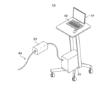
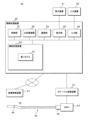
図1は、カテーテルシステム10の概要を説明する説明図である。カテーテルシステム10は、画像診断用カテーテル40と、MDU(Motor Driving Unit)33と、情報処理装置20とを備える。画像診断用カテーテル40は、MDU33を介して情報処理装置20に接続されている。情報処理装置20には、表示装置31および入力装置32が接続されている。入力装置32は、たとえばキーボード、マウス、トラックボールまたはマイク等である。表示装置31と入力装置32とは、一体に積層されて、タッチパネルを構成していてもよい。入力装置32と情報処理装置20とは、一体に構成されていてもよい。
[First embodiment]
FIG. 1 is an explanatory diagram for explaining an overview of a
図2は、画像診断用カテーテル40の概要を説明する説明図である。画像診断用カテーテル40は、プローブ部41と、プローブ部41の端部に配置されたコネクタ部45とを有する。プローブ部41は、コネクタ部45を介してMDU33に接続される。以下の説明では画像診断用カテーテル40のコネクタ部45から遠い側を先端側と記載する。
Figure 2 is an explanatory diagram outlining the
プローブ部41の内部に、シャフト43が挿通されている。シャフト43の先端側に、センサ42が接続されている。プローブ部41の先端部近傍に、環状の先端マーカ44が固定されている。A
MDU33の機能により、プローブ部41の内部でセンサ42およびシャフト43が回転しながら進退可能である。センサ42を一定の速度でMDU33側に向けて引っ張りながら回転させるプルバック操作により、プローブ部41を中心とし、プローブ部41に略垂直な複数枚の横断層像485(図4参照)が、所定の間隔で連続的に撮影される。
The
センサ42は、たとえば超音波の送受信を行なう超音波トランスデューサ、または、近赤外光の照射と反射光の受信を行なうOCT(Optical Coherence Tomography)用の送受信部である。画像診断用カテーテル40が挿入されて、使用される管腔器官は、たとえば血管、膵管、胆管または気管支等である。The
図2は、血管の内側から超音波断層像を撮影する際に用いられるIVUS(Intravascular Ultrasound)用の画像診断用カテーテル40の例を示す。以下の説明では、画像診断用カテーテル40はIVUS用カテーテルである場合を例にして説明する。
Figure 2 shows an example of an imaging
なお、画像診断用カテーテル40は機械的に回転および進退を行なう機械走査方式に限定しない。複数の超音波トランスデューサを環状に配置したセンサ42を用いた、電子ラジアル走査型の画像診断用カテーテル40であってもよい。The
画像診断用カテーテル40は、長手方向に沿って複数の超音波トランスデューサを一列に配置した、いわゆるリニア走査型のセンサ42を有してもよい。画像診断用カテーテル40は、複数の超音波トランスデューサをマトリクス状に配置した、いわゆる2次元アレイ型のセンサ42を有してもよい。The
画像診断用カテーテル40は、血管壁等の管腔壁に加えて、たとえば赤血球等の管腔器官の管腔内部に存在する反射体、および、たとえば心嚢、心臓等の管腔器官の外側に存在する臓器を含む断層像を撮影できる。The
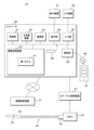
図3は、カテーテルシステム10の構成を説明する説明図である。前述の通りカテーテルシステム10は、情報処理装置20、MDU33および画像診断用カテーテル40を有する。情報処理装置20は、制御部21、主記憶装置22、補助記憶装置23、通信部24、表示部25、入力部26、カテーテル制御部271およびバスを備える。
Figure 3 is an explanatory diagram illustrating the configuration of the
制御部21は、本実施の形態のプログラムを実行する演算制御装置である。制御部21には、一または複数のCPU(Central Processing Unit)、GPU(Graphics Processing Unit)、TPU(Tensor Processing Unit)またはマルチコアCPU等が使用される。制御部21は、バスを介して情報処理装置20を構成するハードウェア各部と接続されている。The
主記憶装置22は、SRAM(Static Random Access Memory)、DRAM(Dynamic Random Access Memory)、フラッシュメモリ等の記憶装置である。主記憶装置22には、制御部21が行なう処理の途中で必要な情報および制御部21で実行中のプログラムが一時的に保存される。The
補助記憶装置23は、SRAM、フラッシュメモリ、ハードディスクまたは磁気テープ等の記憶装置である。補助記憶装置23には、制御部21に実行させるプログラム、第1モデル61およびプログラムの実行に必要な各種データが保存される。通信部24は、情報処理装置20とネットワークとの間の通信を行なうインターフェイスである。The
表示部25は、表示装置31とバスとを接続するインターフェイスである。入力部26は、入力装置32とバスとを接続するインターフェイスである。カテーテル制御部271は、MDU33の制御、センサ42の制御、および、センサ42から受信した信号に基づく横断層像485および縦断層像の生成等を行なう。カテーテル制御部271の機能および構成は、従来から使用されている超音波診断装置と同様であるため、説明を省略する。なお、制御部21が、カテーテル制御部271の機能を実現してもよい。The
情報処理装置20は、HIS(Hospital Information System)等を介して、X線血管撮影装置、X線CT(Computed Tomography)装置、MRI(Magnetic Resonance Imaging)装置、PET(Positron Emission Tomography)装置、または超音波診断装置等の様々な画像診断装置37と接続されている。The
本実施の形態の情報処理装置20は、専用の超音波診断装置、または、超音波診断装置の機能を有するパソコン、タブレット、または、スマートフォン等である。
The
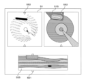
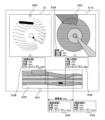
図4は、第1モデル61を説明する説明図である。第1モデル61は、横断層像485を受け付けて、横断層像485に含まれる複数のオブジェクトの種類と、それぞれのオブジェクトの範囲とを関連づけてマッピングしたオブジェクト配置像482を出力するモデルである。第1モデル61は、機械学習により生成されている。
Figure 4 is an explanatory diagram explaining the
図4に示すオブジェクト配置像482において、縦線のハッチングは、「画像診断用カテーテル40の断面」を、横線のハッチングは「管腔器官壁」を、右下がりのハッチングは「管腔器官の内側」を、左下がりのハッチングは「ガイドワイヤ」を、細い格子状のハッチングは「石灰化」をそれぞれ示す。In the
「ガイドワイヤ」は、ガイドワイヤ自体、ガイドワイヤによって生じた多重エコー、および、ガイドワイヤによって生じた音響陰影を含む。同様に「石灰化」は、石灰化した部分自体、石灰化した部分によって生じた多重エコー、および、石灰化した部分によって生じた音響陰影を含む。The term "guidewire" includes the guidewire itself, the multiple echoes produced by the guidewire, and the acoustic shadow produced by the guidewire. Similarly, "calcification" includes the calcified portion itself, the multiple echoes produced by the calcified portion, and the acoustic shadow produced by the calcified portion.
図4中のハッチングは、それぞれのオブジェクトを異なる色で塗り分けていることを模式的に示す。オブジェクトの塗り分けは、それぞれのオブジェクトを区別して表示する方法の一例である。それぞれのオブジェクトの外縁を囲む等の任意の態様により、他のオブジェクトと識別可能に表示してもよい。The hatching in Figure 4 shows a schematic representation of each object being painted in a different color. Painting each object in a different color is one example of a method for displaying each object in a distinctive way. Each object may be displayed in any manner, such as by surrounding its outer edge, to make it distinguishable from other objects.
ここで、「画像診断用カテーテル40の断面」、「管腔器官壁」、「管腔器官の内側」、「ガイドワイヤ」および「石灰化」は、横断層像485に含まれるオブジェクトの例示である。たとえば、「ガイドワイヤ自体」と、「ガイドワイヤによって生じた多重エコー」と、「ガイドワイヤによって生じた音響陰影」とが、それぞれ異なるオブジェクトに分類されてもよい。同様に、管腔器官壁に生じた「プラーク」、「解離」等の病変部が、それぞれ異なるオブジェクトに分類されてもよい。Here, "cross section of
以後の説明においては、縦断層像を生成可能な複数の横断層像485の組を1セットの横断層像485と記載する。同様に、画像診断用カテーテル40を使用して縦断層像を生成可能な1セットの横断層像485を取得することを、1回の画像取得と記載する。1セットの横断層像485の入力を受け付けて、それぞれの横断層像485に対応するオブジェクト配置像482を出力する第1モデル61の例を以下に説明する。In the following description, a set of multiple
1セットの横断層像485は、たとえばMDU33による1回のプルバック操作により取得される。1セットの横断層像485は、ユーザが手動で画像診断用カテーテル40の押し引き操作を行なっている間に取得されてもよい。ここで画像診断用カテーテル40の押し引き操作には、プローブ部41を押し引きする操作と、プローブ部41の内部でセンサ42を押し引きする操作との両方を含む。A set of
たとえば、ユーザはセンサ42を略一定の速度で引き戻す操作、または、押し込む操作を行なう。ユーザが音声入力等により取得開始を指示してから、取得終了を指示するまでの間に取得された横断層像485が、1セットの横断層像485を構成する。For example, the user pulls back or pushes in the
ユーザがセンサ42を押し引きする量を検出するセンサ等を設けてもよい。ユーザがセンサ42を所定の範囲にわたって引き戻す間、または押し込む間に取得された画像が、1セットの横断層像485を構成する。A sensor or the like may be provided to detect the amount by which the user pushes or pulls the
センサ42の位置を検出可能である場合には、ユーザはセンサ42の押し引き操作を任意の速度および向きで行なってもよい。プローブ部41の長手方向に沿った順番に並べ替えた横断層像485が、1セットの横断層像485を構成する。横断層像485間の間隔が一定でない場合には、それぞれの横断層像485にはプローブ部41の長手方向に沿った位置情報が関連づけて記録される。なお、以下の説明では、横断層像485の間隔が一定である場合を例に説明する。If the position of the
前述のとおり、第1モデル61はMDU33によるプルバック操作で得た1セットの横断層像485を受け付けるモデルであっても、センサ42を手動操作で進退させて得た1セットの横断層像485の入力を受け付けるモデルであってもよい。第1モデル61は、1枚の横断層像485の入力を受け付けるモデルであってもよい。第1モデル61は、1回のプルバック操作で得た横断層像485のうちの半分、または1/3等の入力を受け付けるモデルであってもよい。As described above, the
第1モデル61は、たとえばセマンティックセグメンテーションモデルであり、入力層と、ニューラルネットワークと、出力層とを備える。ニューラルネットワークは、たとえばセマンティックセグメンテーションを実現するU-Net構造を有する。U-Net構造は、多層のエンコーダ層と、その後ろに接続された多層のデコーダ層とにより構成される。セマンティックセグメンテーションにより、入力された画像を構成するそれぞれの画素に対して、オブジェクトの種類を示すラベルが付与される。
The
制御部21は、ラベルにしたがってそれぞれの画素の表示方法を定めることにより図4のオブジェクト配置像482に示すように、オブジェクトをその種類ごとに異なる色または地模様等の態様によりマッピングした出力画像を生成できる。The
第1モデル61は、Mask R-CNN(Regions with Convolutional Neural Networks)モデル、その他任意の機械学習アルゴリズムに基づいて生成された、画像のセグメンテーションを実現するモデルであってもよい。The
第1モデル61は、R-CNN等の物体検出を実現するモデルであっても良い。セグメンテーションを行なわずに物体検出を行なうモデルを使用する場合、制御部21は対象を検出した部分をバウンディングボックスで囲むとともに、「石灰化」等の文字をバウンディングボックスの近傍に表示する。The
なお、1セットの横断層像485全体を入力データにすることにより、隣接する横断層像485の情報がオブジェクト配置像482に反映される。したがって、個々の横断層像485中のノイズ等の影響を受けにくく、オブジェクトの範囲を正確に出力する第1モデル61を実現できる。In addition, by using the entire set of transverse
図5は、カテーテルシステム10が表示する画面の例である。図5に示す画面は、横断層像欄51、横オブジェクト配置像欄515および縦オブジェクト配置像欄525を有する。横断層像欄51には、前述の横断層像485が表示されている。横オブジェクト配置像欄515には、横断層像欄51に表示された横断層像485に対応するオブジェクト配置像482が表示されている。
Figure 5 is an example of a screen displayed by the
縦オブジェクト配置像欄525には、縦断層像に対応するオブジェクト配置像482が表示されている。縦断層像に対応するオブジェクト配置像482は、縦断層像と同様に1セットの横断層像485それぞれに対応するオブジェクト配置像482に基づいて形成される。The vertical object
具体的には、それぞれのオブジェクト配置像482から、縦断層像に対応する位置の画素を抽出し、補間処理等を行ない再構成することにより、縦断層像に対応するオブジェクト配置像を形成する。この処理は、1セットの横断層像485から縦断層像を形成する方法と同様であるため、詳細については説明を省略する。Specifically, pixels at positions corresponding to the longitudinal tomographic images are extracted from each
1セットの横断層像485に基づいて3次元データを生成し、それぞれのボクセルに対してオブジェクトの種類を示すラベルを付与する3次元セマンティックセグメンテーションを行なってもよい。3次元セマンティックセグメーション結果により生成した3次元のオブジェクト配置像から、縦断層像に対応するオブジェクト配置像482を生成できる。
Three-dimensional data may be generated based on a set of
縦オブジェクト配置像欄525の縁に、横断層像欄51および横オブジェクト配置像欄515に表示されている横断層像485の位置を示す横断層位置マーカ551が表示されている。横断層像欄51および横オブジェクト配置像欄515の縁近傍に、縦断層像欄52に表示されている縦断層像の位置を示す縦断層位置マーカ552が表示されている。A transverse
ユーザは、入力装置32を操作して横断層位置マーカ551および縦断層位置マーカ552の位置を変更することにより、表示する断面を適宜変更できる。なお、制御部21は、ユーザからの音声入力を受け付けてもよい。The user can change the cross section to be displayed as appropriate by operating the
図5の画面により、ユーザは病変部の長軸方向の状態を確認できる。なお、図5は画面表示の一例であり、これに限定するものではない。たとえば、横断面の集合体としての3次元表示を行なってもよい。The screen in Fig. 5 allows the user to check the state of the lesion in the longitudinal direction. Note that Fig. 5 is an example of a screen display, and is not limited to this. For example, a three-dimensional display as a collection of cross sections may be performed.
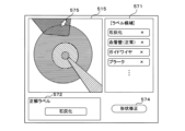
図6は、カテーテルシステム10が表示する画面の例である。ユーザが、「石灰化」を示すオブジェクトを構成する各画素について、「石灰化」という判定が正しい確率を表示するように指示した場合に、制御部21は図6に示す画面を表示する。図6の上部に「石灰化」を示す部分の拡大図を示す。
Figure 6 is an example of a screen displayed by the
なお、それぞれの画素の判定が正しい確率は、図4を使用して説明した第1モデル61から出力される。制御部21は、それぞれの画素が「石灰化」のオブジェクトに分類される確率に基づいて、画素の色を塗り分ける。The probability that the judgment of each pixel is correct is output from the
たとえば制御部21は、「石灰化」を示す色相は共通のまま、明度または彩度にグラデーションをつけることにより、「石灰化」という判定が正しい確率を表現できる。制御部21は、横オブジェクト配置像欄515全体を、各画素に対するオブジェクトの判定の正しさを確率で表す判定確率に基づいて塗分けて表示してもよい。For example, the
ユーザは、図6に示す画面により、「石灰化」という判定がどの程度信頼できる判定であるかを認識できる。仮に、比較的低い確率で「石灰化」であるという判定が出力されている場合には、ユーザは横断層像欄51に表示されている横断層像485を専門的見地に基づいて十分に観察することが望ましい。The user can recognize how reliable the determination of "calcification" is from the screen shown in Figure 6. If the determination of "calcification" is output with a relatively low probability, it is desirable for the user to thoroughly observe the transverse
図7は、カテーテルシステム10が表示する画面の例である。ユーザが、「石灰化」を示す部分に関する根拠を示すように指示した場合に、制御部21は図7に示す画面を表示する。横断層像欄51には「石灰化」という判定の根拠となった根拠領域を示す根拠マーカ561を重畳させた横断層像485が表示されている。根拠マーカ561は、横オブジェクト配置像欄515に表示するオブジェクトの根拠に関する根拠情報の一例である。
Figure 7 is an example of a screen displayed by the
制御部21は、たとえばGrad-CAM(Gradient-weighted Class Activation Mapping)、または、Grad-CAM++等のモデル可視化手法により、根拠領域を抽出する。根拠領域は、学習モデル65に入力された複数の横断層像485中の、「石灰化」と判定された画素の出力に強く影響した領域である。根拠マーカ561は、出力への影響度が高い場所ほど細かいハッチングを用いて表示されている。The
ユーザは、図7に示す画面により、制御部21による判定の根拠が妥当であるか否かを専門的見地に基づいて判断できる。
The user can use the screen shown in Figure 7 to judge from a professional perspective whether the basis for the judgment made by the
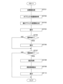
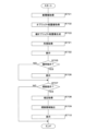
図8は、プログラムの処理の流れを説明するフローチャートである。制御部21は、カテーテル制御部271から1セット分の横断層像485を取得する(ステップS701)。制御部21は、取得した横断層像485を第1モデル61に入力して、横断層像485に含まれる複数のオブジェクトの種類と、それぞれのオブジェクトの範囲とを関連づけたオブジェクト配置像482、および、それぞれの画素に対するオブジェクトの判定が正しい確率を取得する(ステップS702)。
Figure 8 is a flow chart explaining the flow of the program processing. The
制御部21は、1セット分のオブジェクト配置像482に基づいて、オブジェクト配置像482の縦断層像を生成する(ステップS703)。以下の説明ではオブジェクト配置像482の縦断層像を、縦オブジェクト配置像と記載する。制御部21は、ユーザによる縦断層位置マーカ552の操作に対応して、指定された断面による縦オブジェクト配置像を速やかに表示できるよう、生成した縦オブジェクト配置像を補助記憶装置23に記録する。The
制御部21は、図5を使用して説明した画面を表示装置31に表示する(ステップS704)。制御部21は、オブジェクトの判定確率を表示する指示をユーザから受け付けたか否かを判定する(ステップS705)。ユーザは、たとえば横オブジェクト配置像欄515内のオブジェクトをダブルクリックする等の操作により、確率を表示する指示を入力できる。制御部21は、ユーザからの音声入力を受け付けてもよい。The
確率を表示する指示を受け付けたと判定した場合(ステップS705でYES)、制御部21はステップS702で取得したそれぞれの画素に対するオブジェクトの判定が正しい確率に基づいて、図6を使用して説明した画像を表示する(ステップS706)。If it is determined that an instruction to display the probability has been received (YES in step S705), the
確率を表示する指示を受け付けていないと判定した場合(ステップS705でNO)またはステップS706の終了後、制御部21は、根拠を表示する指示をユーザから受け付けたか否かを判定する(ステップS707)。ユーザは、たとえば横オブジェクト配置像欄515内のオブジェクトをスワイプする等の操作により、根拠を表示する指示を入力できる。制御部21は、ユーザからの音声入力を受け付けてもよい。If it is determined that an instruction to display the probability has not been received (NO in step S705) or after step S706 ends, the
根拠を表示する指示を受け付けたと判定した場合(ステップS707でYES)、制御部21は根拠を表示する項目を取得する(ステップS708)。制御部21は、たとえばGrad-CAM、またはGrad-CAM++等のモデル可視化手法により、ステップS708で取得した項目と関連する根拠領域を抽出する(ステップS709)。If it is determined that an instruction to display the basis has been received (YES in step S707), the
制御部21は、図7を使用して説明した画面を使用して、根拠マーカ561を重畳した横断層像485を横断層像欄51に表示する(ステップS710)。根拠を表示する指示を受け付けていないと判定した場合(ステップS707でNO)、またはステップS710の終了後、制御部21は処理を終了する。The
本実施の形態によると、断層像の読影に十分に習熟していないユーザであっても容易に使用できるカテーテルシステム10を提供できる。
According to this embodiment, a
本実施の形態によると、オブジェクト配置像482によりユーザの読影を補助するカテーテルシステム10を提供できる。ユーザは、断層像のどこに何が表示されているかを速やかに把握できるため、診断および処置を行なう上で重要な部分の観察に注力できる。According to this embodiment, a
本実施の形態によると、各画素に対するオブジェクトの判定確率を表示するカテーテルシステム10を提供できる。第1モデル61による判定がどの程度信頼できるかをユーザが把握できるカテーテルシステム10を提供できる。According to this embodiment, a
本実施の形態によると、オブジェクトの判定の根拠を表示するカテーテルシステム10を提供できる。第1モデル61による判定の根拠をユーザが確認できるカテーテルシステム10を提供できる。According to this embodiment, a
[実施の形態2]
本実施の形態は、カテーテル制御装置27と情報処理装置20とが別体であるカテーテルシステム10に関する。実施の形態1と共通する部分については、説明を省略する。
[Embodiment 2]
This embodiment relates to a
図9は、実施の形態2のカテーテルシステム10の構成を説明する説明図である。本実施の形態のカテーテルシステム10は、情報処理装置20、カテーテル制御装置27、MDU33および画像診断用カテーテル40を有する。情報処理装置20は、制御部21、主記憶装置22、補助記憶装置23、通信部24、表示部25、入力部26およびバスを備える。
Figure 9 is an explanatory diagram illustrating the configuration of the
カテーテル制御装置27は、MDU33の制御、センサ42の制御、および、センサ42から受信した信号に基づく横断層像485および縦断層像の生成等を行なう、IVUS用の超音波診断装置である。カテーテル制御装置27の機能および構成は、従来から使用されている超音波診断装置と同様であるため、説明を省略する。The
カテーテル制御装置27と情報処理装置20とは、ケーブルまたは無線通信を介して直接接続されていても、ネットワークを介して接続されていてもよい。The
本実施の形態の情報処理装置20は、汎用のパソコン、タブレット、スマートフォン、大型計算機、大型計算機上で動作する仮想マシン、クラウドコンピューティングシステム、または、量子コンピュータである。情報処理装置20は、分散処理を行なう複数のパソコン等であってもよい。The
[実施の形態3]
本実施の形態は、断層像に描写されている部分の長さおよび面積等の定量的な情報を表示するカテーテルシステム10に関する。実施の形態1と共通する部分については、説明を省略する。
[Embodiment 3]
This embodiment relates to a
図10から図12は、実施の形態3のカテーテルシステムが表示する画面の例である。図10に示す画面においては、図5を使用した画面の横オブジェクト配置像欄515および縦オブジェクト配置像欄525にそれぞれ値ラベル538が表示されている。
Figures 10 to 12 are examples of screens displayed by the catheter system of embodiment 3. In the screen shown in Figure 10, value labels 538 are displayed in the horizontal object
制御部21は、1セットの横断層像485に対応するオブジェクト配置像482に基づいて、ユーザにより指定されたオブジェクトに関連する長さ、面積および体積等の定量的な情報を算出する。たとえば面積を算出する場合には、制御部21はオブジェクトを構成する画素数と、1ピクセル当たりの面積とを積算する。体積を算出する場合には、制御部21は算出した面積にさらに1スライスあたりの厚さを積算する。任意の図形から定量的な情報を算出する方法については公知であるため、詳細については説明を省略する。The
指定されたオブジェクトが「管腔器官の内側」であり、1セットの横断層像485に狭窄している病変が含まれている場合を例にして説明を続ける。制御部21は、それぞれのオブジェクト配置像482から算出した「管腔器官の内側」の径に基づいて、径が最小である位置、すなわち最も狭窄している位置を判定する。制御部21は、所定の判定基準に基づいて病変の両端を判定する。The explanation will continue with an example in which the specified object is the "inside of a hollow organ" and a narrowed lesion is included in one set of
図10においては、横オブジェクト配置像欄515の左下に表示されている値ラベル538には、右下がりのハッチングで示す「管腔器官の内側」の面積と、径の最小値と、径の最大値とがそれぞれ表示されている。In Figure 10, the
縦オブジェクト配置像欄525には、「参照血管」、2つの「病変端部」および「最小径部」の位置を示す、合計4本の縦線が表示されている。「参照血管」は病変がない部分を意味する。The vertical object
それぞれの縦線の端に、対応する値ラベル538が表示されている。値ラベル538には、それぞれの位置における「管腔器官の内側」の径の最小値および最大値と、プラークバーデンが表示されている。2つの「病変端部」を示す2本の縦線の間に、「病変長」が表示されている。At the end of each vertical line, a corresponding
たとえばユーザが「最小径部」の位置を示す縦線の近傍をクリック操作した場合、横断層位置マーカ551が、「最小径部」の位置に移動する。横断層像欄51および横オブジェクト配置像欄515に「最小径部」の横断層像485および横オブジェクト配置像欄515が表示される。ユーザは「最小径部」の状態を確認できる。
For example, if the user clicks near the vertical line indicating the position of the "smallest diameter part," the transverse
同様にユーザが、「参照血管」または「病変端部」の位置を示す縦線の近傍をクリック操作した場合、横断層位置マーカ551は対応する位置に移動する。ユーザは、判断する際のポイントである部分の状態を容易に確認できる。Similarly, when the user clicks near the vertical line indicating the position of the "reference vessel" or "lesion end," the transverse
ユーザは、値ラベル538に表示された組織性状および数値と、学会等で定められた判定基準とに基づいて、診断および治療を行なえる。たとえば、ユーザは血管径、狭窄の程度、病変長、または、石灰化の分布状態に基づいて、血管拡張術の要否および術式等を判断する。制御部21は値ラベル538と共に関連する判定基準に関する情報を表示してもよい。The user can perform diagnosis and treatment based on the tissue properties and values displayed in the
図11は、ユーザが横断層位置マーカ551を縦オブジェクト配置像欄525の右側に移動させた状態を示す。横断層像欄51には、図10とは異なる横断層像485が表示されている。横オブジェクト配置像欄515には、横断層像欄51に対応するオブジェクト配置像482が表示されている。
Figure 11 shows the state in which the user has moved the transverse
図11の横オブジェクト配置像欄515には、縦線のハッチングで示す「画像診断用カテーテル40の断面」、右下がりのハッチングで示す「管腔器官の内側」および格子状のハッチングで示す「石灰化」のオブジェクトがそれぞれ表示されている。オブジェクトが表示されていない部分には、横断層像485が表示されている。ユーザは、「石灰化」のオブジェクトの周囲に存在する管腔器官の状態を確認できる。
In the horizontal object
「石灰化」を示すオブジェクトは、円弧状に表示されている。制御部21は、「管腔器官壁」の中心を基準にして、「石灰化」の角度を算出して、値ラベル538に表示する。The object showing "calcification" is displayed in the shape of an arc. The
角度を算出する方法の具体例を説明する。制御部21は「管腔器官の内側」の外周、すなわち管腔器官壁の内面に近似する形状の円を算出する。制御部21は、算出した円の中心から、「石灰化」を示すオブジェクトの両端にそれぞれ延びるベクトルを抽出する。制御部21は、抽出した2本のベクトル間の角度を算出する。なお、角度を算出する方法は任意であり、これに限定するものではない。
A specific example of a method for calculating an angle will be described. The
制御部21は「管腔器官壁」または「管腔器官の内側」のように円筒形状のオブジェクトについては、内径、外径、最小内径および最大内径をそれぞれ算出して値ラベル538に表示する。制御部21は、図11に示す「石灰化」のように円弧形状のオブジェクトについては、角度を算出して値ラベル538に表示する。なお、制御部21は図11に示す「石灰化」のオブジェクトに対して厚さおよび体積等を表示しても良い。For cylindrical objects such as the "wall of a hollow organ" or the "inside of a hollow organ", the
どの項目を値ラベル538に表示するかは、ユーザがその都度指定してもよい。オブジェクトの種類、形状等に応じて、デフォルトで値ラベル538に表示する項目が定められていても良い。The user may specify which item to display in
図12は、実施の形態3のプログラムの処理の流れを説明するフローチャートである。図12のプログラムは、図8を使用して説明したプログラムのステップS704において、制御部21が図5を使用して説明した画面を表示した後に、ユーザが値ラベル538の表示を指示した場合に実行される。
Figure 12 is a flowchart explaining the processing flow of the program of embodiment 3. The program of Figure 12 is executed when the user instructs display of
ユーザは、たとえば横オブジェクト配置像欄515に表示されたオブジェクトのタップ操作により値ラベル538の表示を指示できる。なお、制御部21は、ユーザからの音声入力を受け付けてもよい。The user can instruct the display of value labels 538, for example, by tapping an object displayed in the horizontal object
制御部21は、ユーザによる指示に基づいて、値ラベル538を表示する対象のオブジェクトの指定を取得する(ステップS721)。制御部21は、指定されたオブジェクトの形状等に基づいて、算出する項目を判定する(ステップS722)。Based on the user's instruction, the
制御部21は、ステップS722で判定した項目を算出する(ステップS723)。制御部21は、図10および図11を使用して説明したように、値ラベル538を表示する(ステップS724)。その後、制御部21は処理を終了する。The
[実施の形態4]
本実施の形態は、断層像を入力した場合に管腔器官、または、管腔器官周辺の状態に関する情報を出力する第2モデル62を使用するカテーテルシステム10に関する。実施の形態1と共通する部分については、説明を省略する。
[Fourth embodiment]
This embodiment relates to a
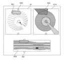
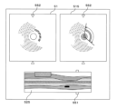
図13は、第2モデル62の構成を説明する説明図である。第2モデル62は、1セットの横断層像485を受け付けて、治療の要否、血流うっ滞の有無、または分岐の有無等、管腔器官の状態、または、当該管腔器官周辺の状態に関する所見を出力するモデルである。なお、「治療の要否」は、管腔器官の内部で処置を行なうIVR(Interventional Radiology)の要否であっても、服薬および食事療法等を含む一般的な治療の要否であってもよい。
Figure 13 is an explanatory diagram explaining the configuration of the
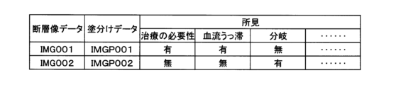
第2モデル62が出力する所見は、複数の項目のそれぞれに対する、「有」、「無」等の所定の選択肢に関する確率である。表1から表5に、第2モデル62が確率を出力する項目の例を示す。表1から表5の1つの行は、一つの項目を示す。第2モデル62は、それぞれの項目ごとに選択肢の確率を出力する。表1から表5に、第2モデル62が出力する所見に含まれる項目の例を示す。The findings output by the
表1は、治療の要否に関する情報を示す。 Table 1 provides information regarding the need for treatment.

表2は、血流情報に関する項目を示す。 Table 2 shows items related to blood flow information.

表3は、管腔器官および管腔器官周囲の定性的形状情報に関する項目を示す。Table 3 shows items related to qualitative shape information of luminal organs and their surroundings.

表4は、管腔器官および管腔器官周囲の性状を示す性状情報に関する項目を示す。Table 4 shows items related to characteristic information indicating the characteristics of hollow organs and the areas surrounding hollow organs.

表4に示す「ステント内狭窄」は、たとえば数か月から数年前に管腔器官内に留置したステントの狭窄の有無を示す。ステント留置の処置の直後に横断層像485を撮影した場合には、留置したステントの狭窄の有無を示す。すなわち、横断層像485は未処置管腔器官の断層像であっても、処置後の経過観察中の管腔器官の断層像であっても、一連の管腔器官内処置の終了直後に撮影した管腔器官の断層像であってもよい。
"In-stent stenosis" in Table 4 indicates the presence or absence of stenosis of a stent placed in a luminal organ several months to several years ago. When the
表5は、管腔器官内に配置されたステント等の留置デバイスの状態を示すデバイス情報に関する項目を示す。Table 5 shows items related to device information indicating the status of an indwelling device, such as a stent, placed within a luminal organ.

表1から表5に示す各項目は例示である。第2モデル62は、表1から表5に示す項目の一部に対する確率を出力してもよい。第2モデル62は、表1から表5に示す項目以外の項目に対する確率を出力してもよい。Each item shown in Tables 1 to 5 is an example. The
表1から表5に示す各項目の選択肢は例示である。たとえば各表で「有」、「無」の2択で表示した項目について、「大」、「小」、「無」等の3択以上の選択肢を用いてもよい。The options for each item shown in Tables 1 to 5 are examples. For example, for items shown in each table with two options, "Yes" and "No," three or more options, such as "Large," "Small," and "No," may be used.
以後の説明においては、1回の画像取得で得た1セットの横断層像485の入力を受け付けて、管腔器官の状態、または、当該管腔器官周辺の状態に関する所見を出力する第2モデル62を例に説明する。なお、第2モデル62は、1枚の横断層像485の入力を受け付けて、管腔器官、または、当該管腔器官周辺の状態に関する所見を出力するモデルであってもよい。In the following description, the
前述のとおり、MDU33による1回のプルバック操作で1回の画像取得を行なってもよい。第2モデル62は、1回のプルバック操作で得た横断層像485のうちの半分、または1/3等、一部分の横断層像485の入力を受け付けて、管腔器官の状態、または、当該管腔器官周辺の状態に関する所見を出力するモデルであってもよい。As described above, one image may be acquired by one pullback operation by the
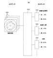
第2モデル62は、入力層と、ニューラルネットワーク629と、複数のソフトマックス層625と、出力層とを備える。ニューラルネットワーク629は、たとえば複数の畳込み層とプーリング層との組と、全結合層とを有するCNN(Convolutional Neural Network)である。表1から表5に示す1つの行について、1つのソフトマックス層625が設けられている。The
入力層には、1セットの横断層像485を走査順に結合して1枚にした画像が入力される。ニューラルネットワーク629およびソフトマックス層625を介して、出力層に表1から表5に示す各項目に対する確率を出力する。The input layer receives an image obtained by combining a set of
たとえば図13においては、「治療の必要性」については「無」である確率が95パーセント、「血流うっ滞」については「無」である確率が90パーセント、「分岐」については「有」である確率が90パーセントである。なお、第2モデル62は、表1から表5についてそれぞれ分かれていてもよい。第2モデル62は、出力する項目ごとにそれぞれ分かれていてもよい。For example, in Figure 13, the probability that "need for treatment" is "no" is 95 percent, the probability that "blood flow stagnation" is "no" is 90 percent, and the probability that "branching" is "yes" is 90 percent. The
ソフトマックス層625の後段に、最も確率が高い選択肢を選択して出力する選択層が設けられていてもよい。A selection layer may be provided after the
第2モデル62には、カテーテル制御部271がセンサ42から取得した音線データ等の、横断層像485を形成する前段階のデータが入力されてもよい。The
図14は、実施の形態4のカテーテルシステム10が表示する画面の例である。図14に示す画面は、横断層像欄51、横オブジェクト配置像欄515および所見欄53を含む。横断層像欄51および横オブジェクト配置像欄515については、図5を使用して説明した実施の形態1のカテーテルシステム10が表示する画面と同一であるため、説明を省略する。
Figure 14 is an example of a screen displayed by the
所見欄53に、所見が表示されている。制御部21は、第2モデル62から出力された所見のうち、所定の閾値よりも確率が高い所見を選択して、所見欄53に表示する。The findings are displayed in the
制御部21は、横断層像欄51に表示中の横断層像485に関連する所見を選択して所見欄53に表示してもよい。図14においては図示を省略するが、制御部21は図5と同様に縦オブジェクト配置像欄525を表示してもよい。The
図15は、実施の形態4のプログラムの処理の流れを説明するフローチャートである。ステップS703までは、図8を使用して説明した実施の形態1のプログラムと同一であるため、説明を省略する。
Figure 15 is a flowchart explaining the processing flow of the program of
制御部21は、ステップS701で取得した横断層像485を第2モデル62に入力して所見を取得する(ステップS731)。制御部21は、図14を使用して説明した画面を表示装置31に表示する(ステップS732)。制御部21は、オブジェクトの判定確率を表示する指示をユーザから受け付けたか否かを判定する(ステップS705)。以後の処理は、図8を使用して説明した実施の形態1のプログラムと同一であるため、説明を省略する。The
本実施の形態によると、オブジェクト配置像482に加えて所見を表示するカテーテルシステム10を提供できる。
According to this embodiment, a
なお、制御部21は、所見欄53に表示した所見の根拠を示す根拠マーカ561を表示してもよい。制御部21は、たとえばGrad-CAM、または、Grad-CAM++等のモデル可視化手法により、第2モデル62から出力された所見に関する根拠領域を抽出できる。The
第1モデル61および第2モデル62には、横断層像485に加えて画像診断装置37を用いて撮影した画像、血圧、心拍数または酸素飽和度等の、リアルタイムで取得した医療情報が入力されてもよい。第1モデル61および第2モデル62には、横断層像485に加えて既往症、身長、体重、過去に画像診断装置37を用いて撮影した画像等の、電子カルテから取得した医療情報が入力されてもよい。In addition to the
このようにする場合、第1モデル61は、横断層像485と医療情報とを受け付けて、横断層像485に含まれる複数のオブジェクトの種類と、それぞれのオブジェクトの範囲とを関連づけてマッピングしたオブジェクト配置像482を出力する。同様に第2モデル62は、横断層像485と医療情報とを受け付けて、管腔器官の状態、または、当該管腔器官周辺の状態に関する所見を出力する。In this case, the
横断層像485以外の医療情報を第1モデル61の入力データに含めることにより、オブジェクトの分類を精度良く行なうカテーテルシステム10を提供できる。横断層像485以外の医療情報を第2モデル62の入力データに含めることにより、精度の高い所見を出力するカテーテルシステム10を提供できる。By including medical information other than the
[実施の形態5]
本実施の形態は、画像診断装置37から取得した画像に画像診断用カテーテル40を用いて撮影した断層像の位置を重畳表示するカテーテルシステム10に関する。実施の形態1と共通する部分については、説明を省略する。
[Embodiment 5]
This embodiment relates to a
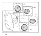
図16は、実施の形態5のカテーテルシステム10が表示する画面の例である。図16に示す画面は他装置画像欄59を含む。他装置画像欄59には、画像診断装置37により撮影された医用画像が表示されている。
Figure 16 is an example of a screen displayed by the
画像診断用カテーテル40が撮影した断層像の位置を示すスキャンエリア591が、縦断層像の外形を示す長方形で他装置画像欄59に重畳表示されている。制御部21は、スキャンエリア591の内側に縦断層像または縦オブジェクト配置像をリアルタイムで表示してもよい。制御部21は、スキャンエリア591の表示形態に関する選択をユーザから受け付けてもよい。
A
画像診断装置37が、X線血管撮影装置である場合を例にして、スキャンエリア591を表示する方法の概要を説明する。センサ42は、X線を透過しないセンサマーカに搭載されている。先端マーカ44およびセンサマーカはX線を透過しないため、X線血管撮影装置で撮影された医用画像中に鮮明に表示される。
The method of displaying the
制御部21は、医用画像から先端マーカ44およびセンサマーカを検出する。検出されたセンサマーカは、センサ42の位置を示す。たとえばMDU33によるプルバック操作を用いて1セットの横断層像485を生成する場合、画像取得時のセンサ42の動作範囲の両端が、スキャンエリア591の短辺の位置に対応する。The
制御部21は、横断層像485の表示レンジと、他装置画像の縮尺に基づいて、スキャンエリア591の短辺の長さを決定する。制御部21は、短辺の位置および短辺の長さから定まる長方形のスキャンエリア591を、医用画像を表示した他装置画像欄59に重畳表示する。The
以上の処理により、画像診断用カテーテル40の先端部分が画像診断装置37の投影面に対して平行ではない場合であっても、制御部21は他装置画像欄59の正しい位置にスキャンエリア591を表示できる。
By performing the above processing, even if the tip of the imaging
図16に戻って説明を続ける。スキャンエリア591内に、複数の横断層位置マーカ551が表示されている。それぞれの横断層位置マーカ551に対応するオブジェクト配置像482を表示する横オブジェクト配置像欄515が他装置画像欄59の周辺に表示されている。ユーザは、入力装置32を介して横断層位置マーカ551を動かすことにより、オブジェクト配置像482の断層位置を適宜変更できる。なお、制御部21は、ユーザからの音声入力を受け付けてもよい。
Returning to Figure 16 for further explanation, multiple transverse
制御部21は、ユーザによる指示に基づいてオブジェクト配置像482と横断層像485とを切り替えて表示してもよい。制御部21はオブジェクト配置像482と横断層像485とを並べて表示してもよい。制御部21は、縦断層像または縦オブジェクト配置像を表示してもよい。The
他装置画像欄59には、画像診断装置37により撮影された医用画像の代わりに、管腔器官を模式的に表したシェーマが表示されてもよい。ユーザが断層像の位置をさらに容易に把握可能なカテーテルシステム10を提供できる。In the other
図17は、実施の形態5のプログラムの処理の流れを説明するフローチャートである。制御部21は、1回の画像取得の際にカテーテル制御部271および画像診断装置37のそれぞれから横断層像485および医用画像を取得する(ステップS751)。
Figure 17 is a flowchart explaining the processing flow of the program of embodiment 5. The
制御部21は、医用画像から先端マーカ44およびセンサマーカを検出する(ステップS752)。たとえばMDU33によるプルバック操作を用いて1セットの横断層像485を生成する場合、制御部21は、プルバック操作の両端で検出されたセンサマーカの位置に基づいて、スキャンエリア591の位置および寸法を決定する。制御部21は、スキャンエリア591に基づいて横断層位置マーカ551の位置を決定する(ステップS753)。The
なお、制御部21はスキャンエリア591に対応する位置を、その後に撮影した医用画像上にリアルタイムでトレースして表示することが望ましい。
It is desirable that the
制御部21は、ステップS751で取得した横断層像485を第1モデル61に入力して、横断層像485に含まれる複数のオブジェクトの種類と、それぞれのオブジェクトの範囲とを関連づけたオブジェクト配置像482、および、それぞれの画素に対するオブジェクトの判定が正しい確率を取得する(ステップS754)。The
制御部21は、1セット分のオブジェクト配置像482に基づいて、縦オブジェクト配置像を生成する(ステップS755)。制御部21は、ユーザによる縦断層位置マーカ552の操作に対応して、指定された断面による縦オブジェクト配置像を速やかに表示できるよう、生成した縦オブジェクト配置像を補助記憶装置23に記録する。The
制御部21は、図16を使用して説明した画面を表示装置31に表示する(ステップS756)。その後、制御部21は処理を終了する。The
本実施の形態によると、画像診断装置37により撮影された医用画像に画像診断用カテーテル40を使用して撮影した断層像または断層像に基づいて生成したオブジェクト配置像482の位置を重畳表示するカテーテルシステム10を提供できる。ユーザは、横断層位置マーカ551を操作することにより表示する横断層像485の位置を容易に変更できる。以上により、ユーザが、断層像と、その周囲の臓器との位置関係を容易に把握できるカテーテルシステム10を提供できる。
According to this embodiment, it is possible to provide a
なお、画像診断装置37はX線血管撮影装置に限定しない。たとえば、体外式プローブまたはTEE(Transesophageal Echocardiography)プローブと組み合わせた超音波診断装置であっても、リアルタイムで画像診断用カテーテル40とは異なる断層像を撮影できる。The
画像診断用カテーテル40が、超音波用のセンサ42とOCT用のセンサ42との両方を搭載している場合には、略同一断面で超音波による横断層像485とOCTによる横断層像485とを撮影できる。When the imaging
制御部21は、分解能に優れたOCTによる横断層像485から得たオブジェクト配置像482を、OCTに比べると深達度に優れた超音波による横断層像485に重畳表示してもよい。そのほか、制御部21は、OCTによる横断層像485と、オブジェクト配置像482、超音波による横断層像485とオブジェクト配置像482を適宜組み合わせて表示してもよい。両者の利点を生かした情報を表示するカテーテルシステム10を提供できる。The
医用画像は、リアルタイムで撮影された医用画像に限定しない。制御部21は、たとえばCT、MRI、PET、X線血管撮影装置または超音波診断装置等の、任意の画像診断装置により撮影されて、電子カルテ等に記録されている医用画像に、スキャンエリア591を重畳表示してもよい。制御部21は、それぞれの画像中に含まれる血管の分岐、心臓の位置等に基づいて、スキャンエリア591の位置を判定する。The medical images are not limited to medical images captured in real time. The
本実施の形態の処理は、画像診断装置37側で実行され、画像診断装置37に接続された表示装置に表示されてもよい。The processing of this embodiment may be executed on the imaging
[実施の形態6]
本実施の形態は、第1モデル61および第2モデル62をそれぞれ生成するプログラムに関する。実施の形態4と共通する部分については、説明を省略する。
Sixth Embodiment
This embodiment relates to a program for generating a
図18は、訓練データDB(Database)のレコードレイアウトを説明する説明図である。訓練データDBは、入力と正解ラベルとを関連づけて記録したデータベースであり、機械学習によるモデルの訓練に使用される。訓練データDBは、断層像データフィールド、塗分けデータフィールドおよび所見フィールドを有する。所見フィールドは、治療の必要性フィールド、血流うっ滞フィールド、分岐フィールド等、第2モデル62が出力する所見に対応するフィールドを有する。
Figure 18 is an explanatory diagram explaining the record layout of the training data DB (database). The training data DB is a database that records inputs and correct labels in association with each other, and is used to train a model using machine learning. The training data DB has a tomographic image data field, a color-coded data field, and a findings field. The findings field has fields corresponding to findings output by the
断層像データフィールドには、縦断層像を生成可能な横断層像485のセットが記録されている。塗分けデータフィールドには、横断層像485を専門家がそれぞれのオブジェクトごとに異なる色または地模様で塗分けた画像のセットが記録されている。すなわち、塗分けデータフィールドには、横断層像485を構成するそれぞれの画素が対応するオブジェクトが記録されている。
In the tomographic image data field, a set of
治療の必要性フィールドには、断層像データフィールドに記録された横断層像485に基づいて、専門家が治療の必要性を判断した結果が表示されている。同様に、血流うっ滞フィールドには血流うっ滞の有無が、分岐フィールドには分岐の有無がそれぞれ記録されている。The necessity of treatment field displays the result of an expert's judgment on the necessity of treatment based on the
訓練データDBには、画像診断用カテーテル40を用いて撮影した横断層像485のセットと、専門の医師等が判断した塗分けた画像のセットおよび治療の必要性との組み合わせが大量に記録されている。なお、以下の説明では、セットを構成する横断層像485同士の間隔が一定である場合を例にして説明する。The training data DB contains a large number of records of sets of transverse
第1モデル61を生成する場合には、断層像データフィールドに記録された横断層像485のセットが入力データに、塗分けデータフィールドに記録された画像のセットが正解データに使用される。第2モデル62を生成する場合には、断層像データフィールドに記録された横断層像485のセットが入力データに、所見フィールドのそれぞれに記録されたデータが正解ラベルに使用される。When generating the
訓練データDBは、たとえば第1モデル61生成用のデータベースと、第2モデル62生成用のデータベースとに分けて作成されていてもよい。The training data DB may be created, for example, as separate databases for generating the
図19は、実施の形態5のプログラムの処理の流れを説明するフローチャートである。情報処理装置20を用いて第1モデル61の機械学習を行なう場合を例にして説明する。
Figure 19 is a flowchart explaining the processing flow of the program of embodiment 5. An example will be explained in which machine learning of the
図19のプログラムは情報処理装置20とは別のハードウェアで実行され、機械学習が完了した第1モデル61がネットワークを介して補助記憶装置23に複写されてもよい。一つのハードウェアで学習させた第1モデル61を、複数の情報処理装置20で使用できる。
The program in FIG. 19 may be executed on hardware separate from the
図19のプログラムの実行に先立ち、たとえばセマンティックセグメンテーションを実現するU-Net構造等の未学習のモデルが準備されている。前述のとおり、U-Net構造は、多層のエンコーダ層と、その後ろに接続された多層のデコーダ層とにより構成される。図19のプログラムにより、準備されたモデルの各パラメータが調整されて、機械学習が行なわれる。 Prior to executing the program in Figure 19, an untrained model, such as a U-Net structure that realizes semantic segmentation, is prepared. As mentioned above, the U-Net structure is composed of multiple encoder layers followed by multiple decoder layers. The program in Figure 19 adjusts each parameter of the prepared model and performs machine learning.
制御部21は、訓練データDBから1エポックの訓練に使用する訓練レコードを取得する(ステップS761)。1エポックの訓練に使用する訓練レコードの数は、いわゆるハイパーパラメータであり、適宜定められている。The
制御部21は、取得したそれぞれの訓練レコードに含まれる入力データから、入力画像を生成する(ステップS762)。具体的には、制御部21は断層像フィールドに含まれる横断層像485を走査順に結合して1枚にした画像を生成する。なお、断層像データフィールドに、結合済の横断層像が記録されていてもよい。The
制御部21は、取得したそれぞれの訓練レコードに含まれる塗分けデータから、正解画像を生成する(ステップS763)。具体的には、制御部21は塗分けデータフィールドに含まれる塗分け画像を走査順に結合して1枚にした画像を生成する。なお、塗分けデータフィールドに、結合済の塗分け画像が記録されていてもよい。The
制御部21は、モデルの入力層に入力画像が入力された場合に、出力層から正解画像ラベルが出力されるように、モデルのパラメータを調整する(ステップS764)。The
制御部21は、処理を終了するか否かを判定する(ステップS765)。たとえば、制御部21は所定のエポック数の学習を終了した場合に、処理を終了すると判定する。制御部21は、訓練データDBからテストデータを取得して機械学習中のモデルに入力し、所定の精度の出力が得られた場合に処理を終了すると判定してもよい。The
処理を終了しないと判定した場合(ステップS765でNO)、制御部21はステップS761に戻る。処理を終了すると判定した場合(ステップS765でYES)、制御部21は学習済のモデルのパラメータを補助記憶装置23に記録する(ステップS767)。その後、制御部21は処理を終了する。以上の処理により、学習済のモデルが生成される。If it is determined that the process is not to be terminated (NO in step S765), the
図20は、実施の形態6のプログラムの処理の流れを説明するフローチャートである。図19と同様に、情報処理装置20を用いて第2モデル62の機械学習を行なう場合を例にして説明する。
Figure 20 is a flowchart explaining the processing flow of the program of embodiment 6. As with Figure 19, an example will be explained in which machine learning of the
図20のプログラムの実行に先立ち、たとえば畳み込み層、プーリング層、全結合層を含むニューラルネットワーク629と、ソフトマックス層625とを有するCNN等の未学習のモデルが準備されている。未学習のモデルは、CNNに限定しない。たとえば決定木またはランダムフォレスト等の任意のタイプのモデルを使用できる。図20のプログラムにより、準備されたモデルの各パラメータが調整されて、機械学習が行なわれる。Prior to execution of the program in FIG. 20, an untrained model such as a CNN having a
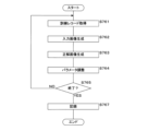
制御部21は、訓練データDBから1エポックの訓練に使用する訓練レコードを取得する(ステップS771)。制御部21は、取得したそれぞれの訓練レコードに含まれる入力データから、入力画像を生成する(ステップS772)。The
制御部21は、モデルの入力層に入力データベクトルが入力された場合に、出力層から所見フィールドに記録された正解ラベルが出力されるように、モデルのパラメータを調整する(ステップS773)。The
制御部21は、処理を終了するか否かを判定する(ステップS774)。処理を終了しないと判定した場合(ステップS774でNO)、制御部21はステップS771に戻る。処理を終了すると判定した場合(ステップS774でYES)、制御部21は学習済のモデルのパラメータを補助記憶装置23に記録する(ステップS775)。その後、制御部21は処理を終了する。以上の処理により、学習済のモデルが生成される。The
本実施の形態によると、機械学習により第1学習モデル651および第2学習モデル652を生成できる。 According to this embodiment, a first learning model 651 and a second learning model 652 can be generated by machine learning.
[実施の形態7]
本実施の形態は、学習モデル65により出力された所見をユーザが修正可能なカテーテルシステム10に関する。実施の形態1と共通する部分については、説明を省略する。
[Embodiment 7]
This embodiment relates to a
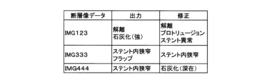
図21は、第1修正DBのレコードレイアウトを説明する説明図である。第1修正DBは、カテーテルシステム10が出力したオブジェクト配置像482と、ユーザによる修正とを関連づけた修正情報を記録したデータベースである。
Figure 21 is an explanatory diagram explaining the record layout of the first correction DB. The first correction DB is a database that records correction information that associates the
第1修正DBは、断層像データフィールド、出力データフィールドおよび修正データフィールドを有する。断層像データフィールドには、縦断層像を生成可能な横断層像485のセットが記録されている。出力データフィールドには、制御部21が表示装置31に出力したオブジェクト配置像482が記録されている。修正データフィールドには、ユーザが修正したオブジェクト配置像482が記録されている。第1修正DBは、横断層像485のセットに対するユーザによる修正ごとに、1つのレコードを有する。
The first correction DB has a tomographic image data field, an output data field, and a correction data field. The tomographic image data field records a set of
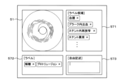
図22は、実施の形態7のカテーテルシステム10が表示する画面の例である。図22は、たとえば図6を使用して説明した画面の表示中に、ユーザがオブジェクト配置像482の修正を指示した場合に制御部21が表示装置31に表示する画面である。
Figure 22 is an example of a screen displayed by the
図22に示す画面は、横オブジェクト配置像欄515、候補ラベル欄571、正解ラベル欄572および形状修正ボタン574を含む。候補ラベル欄571には、オブジェクトの種類を示すラベルの候補が表示されている。正解ラベル欄572には、ユーザが正解であると判断したラベルが表示されている。
The screen shown in Figure 22 includes a horizontal object
ユーザはカーソル575を使用して種類を変更するオブジェクトを指定する。その後、ユーザは、候補ラベル欄571に表示されているラベルを正解ラベル欄572にドラッグアンドドロップ操作することで、正しいラベルを入力する。The user uses
制御部21は正解ラベル欄572に表示されているラベルをユーザにより指定されたラベルに入れ替える。制御部21は、カーソル575により指定されたオブジェクトをユーザにより選択されたラベルに対応する色または地模様に塗り替える。The
なお、制御部21は音声入力による入力を受け付けてもよい。たとえばユーザが「石灰化を血腫に変更」と発声した場合に、制御部21は「石灰化」の色または地模様で表示されたオブジェクトを「血腫」の色または地模様に塗り替える。The
ユーザが形状修正ボタン574を選択した場合、制御部21はペイントソフト様のユーザインターフェースによりオブジェクト配置像482の塗分け形状の修正を受け付ける。ペイントソフトは従来から使用されているため、詳細な説明は省略する。
When the user selects the
以上により、ユーザはオブジェクト配置像482を適宜修正できる。制御部21はユーザにより修正されたオブジェクト配置像482を、修正前のオブジェクト配置像482および横断層像485のセットとともに、第1修正DBに記録する。
In this way, the user can appropriately modify the
図23は、第2修正DBのレコードレイアウトを説明する説明図である。第2修正DBは、カテーテルシステム10が出力した所見と、ユーザによる修正とを関連づけた修正情報を記録したデータベースである。修正DBは、横断層像485のセットに対するユーザによる修正ごとに、1つのレコードを有する。
Figure 23 is an explanatory diagram explaining the record layout of the second revision DB. The second revision DB is a database that records revision information that associates findings output by the
修正DBは、断層像データフィールド、出力フィールドおよび修正フィールドを有する。断層像データフィールドには、縦断層像を生成可能な横断層像485のセットが記録されている。出力フィールドには、制御部21が表示装置31に出力した所見が記録されている。修正フィールドには、ユーザが修正した所見が記録されている。The correction DB has a tomographic image data field, an output field, and a correction field. The tomographic image data field records a set of
図24は、実施の形態7のカテーテルシステム10が表示する画面の例である。図24は、たとえば図14を使用して説明した画面の表示中に、ユーザが所見欄53の修正を指示した場合に制御部21が表示装置31に表示する画面である。
Figure 24 is an example of a screen displayed by the
図24に示す画面は、横断層像欄51、候補ラベル欄571、正解ラベル欄572および自由記述欄573を含む。候補ラベル欄571には、定性的所見を示すラベルの候補が表示されている。正解ラベル欄572には、ユーザが正解であると判断したラベルが表示されている。The screen shown in FIG. 24 includes a
ユーザは、候補ラベル欄571と正解ラベル欄572との間でラベルをドラッグアンドドロップ操作することで、正しい所見を入力できる。なお、制御部21は音声入力による入力を受け付けてもよい。たとえばユーザが「正解、血腫」と発声した場合に、制御部21は候補ラベル欄571の1行目の「血腫」のラベルを正解ラベル欄572に移動させる。The user can input the correct findings by dragging and dropping the labels between the
候補ラベル欄571に適切な所見を表すラベルが見付からない場合、ユーザは自由記述欄573を使用して任意の所見を入力できる。図示を省略するが、定量的な所見に関しても同様にユーザが適宜変更できる。If a label that represents an appropriate finding cannot be found in the
制御部21は、図24の画面を使用してユーザが入力した修正内容を、図23を使用して説明した修正DBに記録する。
The
図22および図24の画面を使用してユーザが修正した内容は、患者の診療結果を記録する電子カルテに添付されてもよい。第1修正DBおよび第2修正DBに記録されたデータは、第1モデル61および第2モデル62の再学習、および、機械学習のエンジニアによる機械学習時に用いるハイパーパラメータの修正等に活用される。22 and 24 may be attached to an electronic medical record that records the results of medical treatment of the patient. The data recorded in the first revision DB and the second revision DB is used for re-learning the
[実施の形態8]
図25は、実施の形態8のカテーテルシステム10の機能ブロック図である。カテーテルシステム10は、カテーテルシステム10は、取得部86および出力部87を備える。取得部86は、管腔器官に挿入された画像診断用カテーテルを用いて生成された断層像を取得する。出力部87は、取得部86が取得した断層像を入力した場合に、該断層像に含まれる複数のオブジェクトの種類と、それぞれのオブジェクトの範囲とを関連づけて出力するモデル65に、取得した断層像を入力して、モデル65から出力されたオブジェクトの種類と範囲とを出力する。
[Embodiment 8]
25 is a functional block diagram of the
[実施の形態9]
図26は、実施の形態9のカテーテルシステムの構成を説明する説明図である。本実施の形態は、汎用のコンピュータ90とプログラム97とを組み合わせて動作させることにより、本実施の形態の情報処理装置20を実現する形態に関する。図26は、実施の形態9の情報処理装置20の構成を示す説明図である。実施の形態2と共通する部分については、説明を省略する。
Ninth Embodiment
Fig. 26 is an explanatory diagram for explaining the configuration of a catheter system according to a ninth embodiment. This embodiment relates to a form in which an
本実施の形態のカテーテルシステム10は、コンピュータ90を含む。コンピュータ90は、制御部21、主記憶装置22、補助記憶装置23、通信部24、表示部25、入力部26、読取部29およびバスを備える。コンピュータ90は、汎用のパーソナルコンピュータ、タブレット、スマートフォンまたはサーバコンピュータ等の情報機器である。The
プログラム97は、可搬型記録媒体96に記録されている。制御部21は、読取部29を介してプログラム97を読み込み、補助記憶装置23に保存する。また制御部21は、コンピュータ90内に実装されたフラッシュメモリ等の半導体メモリ98に記憶されたプログラム97を読出してもよい。さらに、制御部21は、通信部24および図示しないネットワークを介して接続される図示しない他のサーバコンピュータからプログラム97をダウンロードして補助記憶装置23に保存してもよい。
The
プログラム97は、コンピュータ90の制御プログラムとしてインストールされ、主記憶装置22にロードして実行される。これにより、コンピュータ90は上述した情報処理装置20として機能する。The
各実施例で記載されている技術的特徴(構成要件)はお互いに組合せ可能であり、組み合わせすることにより、新しい技術的特徴を形成することができる。
今回開示された実施の形態はすべての点で例示であって、制限的なものでは無いと考えられるべきである。本発明の範囲は、上記した意味では無く、請求の範囲によって示され、請求の範囲と均等の意味および範囲内でのすべての変更が含まれることが意図される。
The technical features (constituent elements) described in each embodiment can be combined with each other, and by combining them, new technical features can be formed.
The embodiments disclosed herein are illustrative in all respects and should not be considered as limiting. The scope of the present invention is defined by the claims, not by the above meaning, and is intended to include all modifications within the scope and meaning equivalent to the claims.
10 カテーテルシステム
20 情報処理装置
21 制御部
22 主記憶装置
23 補助記憶装置
24 通信部
25 表示部
26 入力部
27 カテーテル制御装置
271 カテーテル制御部
29 読取部
31 表示装置
32 入力装置
33 MDU
37 画像診断装置
40 画像診断用カテーテル
41 プローブ部
42 センサ
43 シャフト
44 先端マーカ
45 コネクタ部
482 オブジェクト配置像
485 横断層像(断層像)
51 横断層像欄
515 横オブジェクト配置像欄
52 縦断層像欄
525 縦オブジェクト配置像欄
53 所見欄
538 値ラベル
551 横断層位置マーカ
552 縦断層位置マーカ
561 根拠マーカ
571 候補ラベル欄
572 正解ラベル欄
573 自由記述欄
574 形状修正ボタン
575 カーソル
591 スキャンエリア
61 第1モデル
62 第2モデル
625 ソフトマックス層
629 ニューラルネットワーク
65 学習モデル(モデル)
651 第1学習モデル
652 第2学習モデル
86 取得部
87 出力部
90 コンピュータ
96 可搬型記録媒体
97 プログラム
98 半導体メモリ
REFERENCE SIGNS
37
51 Transverse
651 First learning model 652
Claims (20)
断層像を入力した場合に、該断層像に含まれる複数のオブジェクトの種類と、それぞれの前記オブジェクトの範囲とを関連づけて出力する第1モデルに、取得した前記断層像を入力して、前記第1モデルから出力されたオブジェクトの種類と範囲とを取得し、
前記断層像は、前記管腔器官および前記管腔器官の周辺を前記管腔器官の長手方向に対して交差する方向に切断した断面を示す横断層像であり、
複数枚の前記横断層像のそれぞれについて、前記オブジェクトの種類および範囲をマッピングして記憶し、
複数枚の前記横断層像に基づいて生成された、前記管腔器官および前記管腔器官の周辺を前記管腔器官の長手方向と平行な方向に切断した断面を示す縦断層像に前記オブジェクトの種類および範囲をマッピングして出力する
処理をコンピュータに実行させるプログラム。 A tomographic image is obtained using an imaging catheter inserted into the tubular organ;
inputting the acquired tomographic image into a first model which, when a tomographic image is input, outputs the types of a plurality of objects included in the tomographic image in association with the ranges of each of the objects, and acquiring the types and ranges of the objects output from the first model;
the tomographic image is a transverse image showing a cross section of the hollow organ and the periphery of the hollow organ cut in a direction intersecting with a longitudinal direction of the hollow organ,
Mapping and storing the type and range of the object for each of the plurality of cross-sectional images;
The type and range of the object are mapped onto a longitudinal section image, which is generated based on the multiple transverse section images and shows a cross section of the hollow organ and its surroundings cut in a direction parallel to the longitudinal direction of the hollow organ, and output.
A program that causes a computer to carry out processing.
請求項1に記載のプログラム。 The program according to claim 1 , wherein the object type and range are displayed in a different manner for each object type.
前記縦断層像に、前記選択断層像の位置を示すマーカを表示する
請求項1または請求項2に記載のプログラム。 outputting the longitudinal tomographic image and a selected tomographic image selected from the plurality of transverse tomographic images at the same time;
A marker indicating the position of the selected tomographic image is displayed on the longitudinal tomographic image.
The program according to claim 1 or 2 .
請求項1から請求項3のいずれか一つに記載のプログラム。 4. The program according to claim 1, further comprising: displaying, in a superimposed manner, a marker indicating a position of the acquired tomographic image on a medical image or a schema different from the acquired tomographic image.
算出した寸法、面積または体積を出力する
請求項1から請求項4のいずれか一つに記載のプログラム。 Calculating a size, area or volume of the object based on the extent of the object;
The program according to any one of claims 1 to 4, further comprising: outputting the calculated dimension, area or volume.
算出した角度を出力する
請求項1から請求項4のいずれか一つに記載のプログラム。 calculating an angle of a range in which the hollow organ is in a state corresponding to one object selected from the objects, based on the range of the one object selected from the objects;
5. The program according to claim 1, further comprising: outputting the calculated angle.
断層像を入力した場合に、該断層像に含まれる複数のオブジェクトの種類と、それぞれの前記オブジェクトの範囲とを関連づけて出力する第1モデルに、取得した前記断層像を入力して、前記第1モデルから出力されたオブジェクトの種類と範囲とを取得し、
前記オブジェクトから選択された1つのオブジェクトの範囲に基づいて、前記管腔器官が当該オブジェクトに対応する状態である範囲の角度を算出し、
算出した角度を出力する
処理をコンピュータに実行させるプログラム。 A tomographic image is obtained using an imaging catheter inserted into the tubular organ;
inputting the acquired tomographic image into a first model which, when a tomographic image is input, outputs the types of a plurality of objects included in the tomographic image in association with the ranges of each of the objects, and acquiring the types and ranges of the objects output from the first model;
calculating an angle of a range in which the hollow organ is in a state corresponding to one object selected from the objects, based on the range of the one object selected from the objects;
Output the calculated angle
A program that causes a computer to carry out processing.
請求項1から請求項7のいずれか一つに記載のプログラム。 The program according to claim 1 , further comprising: outputting, together with the type and range of the object output from the first model, grounds information regarding the type and range of the object.
前記オブジェクトの種類および範囲を、前記オブジェクトの種類ごとに定めた色相で表示するとともに、前記オブジェクトに該当する確率の相違をそれぞれの画素の明度または彩度の相違で表示する
請求項1から請求項8のいずれか一つに記載のプログラム。 The first model outputs a probability that each pixel constituting the input tomographic image corresponds to one of the objects;
The program according to any one of claims 1 to 8, wherein the type and range of the object are displayed in a hue defined for each type of object, and the difference in the probability of the object being included is displayed by the difference in brightness or saturation of each pixel .
請求項1から請求項9のいずれか一つに記載のプログラム。 The program according to claim 1 , further comprising: receiving a modification to a type or range of the object.
請求項10に記載のプログラム。 Recording correction information that associates the acquired tomographic image with a correction regarding the type or range of the object.
The program according to claim 10 .
請求項11に記載のプログラム。 Re-learning the first model based on the correction information.
The program according to claim 11 .
請求項1から請求項10のいずれか一つに記載のプログラム。 The program according to any one of claims 1 to 10, further comprising: inputting the acquired tomographic image into a second model that outputs information regarding the condition of a tubular organ or the area surrounding the tubular organ when a tomographic image is input; and further outputting information output from the second model.
請求項13に記載のプログラム。 Accepting a modification to the state of the hollow organ or the surroundings of the hollow organ
The program according to claim 13 .
請求項14に記載のプログラム。 and recording correction information that associates the acquired tomographic image with a correction to the state of the hollow organ or the surroundings of the hollow organ.
The program according to claim 14 .
請求項15に記載のプログラム。 Re-learning the second model based on the correction information.
The program according to claim 15 .
断層像を入力した場合に、該断層像に含まれる複数のオブジェクトの種類と、それぞれの前記オブジェクトの範囲とを関連づけて出力する第1モデルに、取得した前記断層像を入力して、前記第1モデルから出力されたオブジェクトの種類と範囲とを取得し、
前記断層像は、前記管腔器官および前記管腔器官の周辺を前記管腔器官の長手方向に対して交差する方向に切断した断面を示す横断層像であり、
複数枚の前記横断層像のそれぞれについて、前記オブジェクトの種類および範囲をマッピングして記憶し、
複数枚の前記横断層像に基づいて生成された、前記管腔器官および前記管腔器官の周辺を前記管腔器官の長手方向と平行な方向に切断した断面を示す縦断層像に前記オブジェクトの種類および範囲をマッピングして出力する
処理をコンピュータが実行する情報処理方法。 A tomographic image is obtained using an imaging catheter inserted into the tubular organ;
inputting the acquired tomographic image into a first model which, when a tomographic image is input, outputs the types of a plurality of objects included in the tomographic image in association with the ranges of each of the objects, and acquires the types and ranges of the objects output from the first model;
the tomographic image is a transverse image showing a cross section of the hollow organ and the periphery of the hollow organ cut in a direction intersecting with a longitudinal direction of the hollow organ,
Mapping and storing the type and range of the object for each of the plurality of cross-sectional images;
The type and range of the object are mapped onto a longitudinal section image, which is generated based on the multiple transverse section images and shows a cross section of the hollow organ and its surroundings cut in a direction parallel to the longitudinal direction of the hollow organ, and output.
An information processing method in which processing is performed by a computer.
断層像を入力した場合に、該断層像に含まれる複数のオブジェクトの種類と、それぞれの前記オブジェクトの範囲とを関連づけて出力する第1モデルに、取得した前記断層像を入力して、前記第1モデルから出力されたオブジェクトの種類と範囲とを取得し、
前記オブジェクトから選択された1つのオブジェクトの範囲に基づいて、前記管腔器官が当該オブジェクトに対応する状態である範囲の角度を算出し、
算出した角度を出力する
処理をコンピュータが実行する情報処理方法。 A tomographic image is obtained using an imaging catheter inserted into the tubular organ;
inputting the acquired tomographic image into a first model which, when a tomographic image is input, outputs the types of a plurality of objects included in the tomographic image in association with the ranges of each of the objects, and acquiring the types and ranges of the objects output from the first model;
calculating an angle of a range in which the hollow organ is in a state corresponding to one object selected from the objects, based on the range of the one object selected from the objects;
Output the calculated angle
An information processing method in which processing is performed by a computer.
前記取得部が取得した断層像を入力した場合に、該断層像に含まれる複数のオブジェクトの種類と、それぞれの前記オブジェクトの範囲とを関連づけて出力するモデルに、取得した前記断層像を入力して、前記モデルから出力されたオブジェクトの種類と範囲とを取得する第2取得部とを備え、
前記断層像は、前記管腔器官および前記管腔器官の周辺を前記管腔器官の長手方向に対して交差する方向に切断した断面を示す横断層像であり、
前記第2取得部が取得した複数枚の前記横断層像のそれぞれについて、前記オブジェクトの種類および範囲をマッピングして記憶する記憶部と、
複数枚の前記横断層像に基づいて生成された、前記管腔器官および前記管腔器官の周辺を前記管腔器官の長手方向と平行な方向に切断した断面を示す縦断層像に前記オブジェクトの種類および範囲をマッピングして出力する出力部とをさらに備える
情報処理システム。 an acquisition unit that acquires a tomographic image generated using a diagnostic imaging catheter inserted into a hollow organ;
a second acquisition unit that, when the tomographic image acquired by the acquisition unit is input, inputs the acquired tomographic image into a model that outputs a correspondence between the types of a plurality of objects included in the tomographic image and the ranges of each of the objects, and acquires the types and ranges of the objects output from the model;
the tomographic image is a transverse image showing a cross section of the hollow organ and the periphery of the hollow organ cut in a direction intersecting with a longitudinal direction of the hollow organ,
A storage unit that maps and stores the type and range of the object for each of the plurality of cross-sectional images acquired by the second acquisition unit;
and an output unit that maps the type and range of the object onto a longitudinal section image that shows a cross section of the hollow organ and its periphery cut in a direction parallel to the longitudinal direction of the hollow organ, the longitudinal section image being generated based on the plurality of transverse section images, and outputs the mapped type and range of the object.
Information processing system.
前記取得部が取得した断層像を入力した場合に、該断層像に含まれる複数のオブジェクトの種類と、それぞれの前記オブジェクトの範囲とを関連づけて出力するモデルに、取得した前記断層像を入力して、前記モデルから出力されたオブジェクトの種類と範囲とを取得する第2取得部と、
前記オブジェクトから選択された1つのオブジェクトの範囲に基づいて、前記管腔器官が当該オブジェクトに対応する状態である範囲の角度を算出する算出部と、
算出した角度を出力する出力部と
を備える情報処理システム。 an acquisition unit that acquires a tomographic image generated using a diagnostic imaging catheter inserted into a hollow organ;
a second acquisition unit that inputs the acquired tomographic image into a model that outputs a model in which the types of a plurality of objects included in the tomographic image are associated with the ranges of each of the objects when the tomographic image acquired by the acquisition unit is input, and acquires the types and ranges of the objects output from the model;
a calculation unit that calculates an angle of a range in which the tubular organ is in a state corresponding to one object selected from the objects, based on the range of the one object;
An output section that outputs the calculated angle;
An information processing system comprising:
Applications Claiming Priority (3)
| Application Number | Priority Date | Filing Date | Title |
|---|---|---|---|
| JP2020061510 | 2020-03-30 | ||
| JP2020061510 | 2020-03-30 | ||
| PCT/JP2021/009337 WO2021199967A1 (en) | 2020-03-30 | 2021-03-09 | Program, information processing method, learning model generation method, learning model relearning method, and information processing system |
Publications (2)
| Publication Number | Publication Date |
|---|---|
| JPWO2021199967A1 JPWO2021199967A1 (en) | 2021-10-07 |
| JP7581331B2 true JP7581331B2 (en) | 2024-11-12 |
Family
ID=77928540
Family Applications (1)
| Application Number | Title | Priority Date | Filing Date |
|---|---|---|---|
| JP2022511733A Active JP7581331B2 (en) | 2020-03-30 | 2021-03-09 | Program, information processing method, learning model generation method, learning model re-learning method, and information processing system |
Country Status (4)
| Country | Link |
|---|---|
| US (1) | US12444170B2 (en) |
| JP (1) | JP7581331B2 (en) |
| CN (1) | CN115701939A (en) |
| WO (1) | WO2021199967A1 (en) |
Families Citing this family (2)
| Publication number | Priority date | Publication date | Assignee | Title |
|---|---|---|---|---|
| EP4398805A1 (en) * | 2021-10-08 | 2024-07-17 | Boston Scientific Scimed, Inc. | Medical device systems for automatic lesion assessment |
| JP7615067B2 (en) * | 2022-02-07 | 2025-01-16 | 株式会社東芝 | Ultrasound data evaluation system, ultrasound data evaluation method, and judgment model generation method |
Citations (8)
| Publication number | Priority date | Publication date | Assignee | Title |
|---|---|---|---|---|
| JP2007007410A (en) | 2005-06-30 | 2007-01-18 | Siemens Ag | Intraluminal imaging apparatus and method |
| WO2007145093A1 (en) | 2006-06-12 | 2007-12-21 | Hitachi Medical Corporation | Image diagnosis support device and image diagnosis support program |
| JP2008535566A (en) | 2005-04-05 | 2008-09-04 | ボストン サイエンティフィック リミテッド | System and method for image segmentation using a multi-stage classifier |
| JP2010075616A (en) | 2008-09-29 | 2010-04-08 | Yamaguchi Univ | Discrimination of nature of tissue using sparse coding method |
| JP2010220902A (en) | 2009-03-25 | 2010-10-07 | Fujifilm Corp | Recognition result determination apparatus and method, and program |
| JP2017042558A (en) | 2015-08-28 | 2017-03-02 | キヤノン株式会社 | Image processing apparatus, image processing method, and program |
| JP2019518581A (en) | 2016-06-08 | 2019-07-04 | リサーチ ディヴェロプメント ファウンデーション | System and method for automated feature analysis and risk assessment of coronary artery plaques using intravascular optical coherence tomography |
| JP2020010805A (en) | 2018-07-17 | 2020-01-23 | 大日本印刷株式会社 | Specification device, program, specification method, information processing device, and specifier |
Family Cites Families (15)
| Publication number | Priority date | Publication date | Assignee | Title |
|---|---|---|---|---|
| JPH03102477A (en) * | 1989-06-26 | 1991-04-26 | Fuji Photo Film Co Ltd | Radial image processing device |
| US5157733A (en) | 1990-06-08 | 1992-10-20 | Fuji Photo Film Co., Ltd. | Radiation image processing apparatus, determination apparatus, and radiation image read-out apparatus |
| JP3102477B2 (en) * | 1998-08-04 | 2000-10-23 | 日本電気株式会社 | Head positioning control device for information recording device |
| CN101953696B (en) * | 2010-09-30 | 2012-11-14 | 华北电力大学(保定) | Method for measuring three-dimensional morphological parameters of blood vessel in ICUS image sequence |
| KR101360386B1 (en) * | 2012-01-18 | 2014-02-07 | 연세대학교 산학협력단 | Computed tomography apparatus of catheter insertion type, and method applied to the same |
| CA2896505A1 (en) * | 2013-01-08 | 2014-07-17 | Volcano Corporation | Method for focused acoustic computed tomography (fact) |
| EP3838124A1 (en) * | 2014-12-12 | 2021-06-23 | Lightlab Imaging, Inc. | Systems to detect and display endovascular features |
| US10092264B2 (en) | 2015-08-27 | 2018-10-09 | Canon Kabushiki Kaisha | Image processing apparatus, image processing method, radiation imaging system, and non-transitory computer-readable storage medium |
| JP6866310B2 (en) * | 2016-01-26 | 2021-04-28 | テルモ株式会社 | Image display device and its control method |
| WO2017164071A1 (en) | 2016-03-22 | 2017-09-28 | テルモ株式会社 | Catheter and image diagnosis device |
| JP6749852B2 (en) * | 2017-01-31 | 2020-09-02 | テルモ株式会社 | catheter |
| US11596384B2 (en) * | 2018-10-26 | 2023-03-07 | Philips Image Guided Therapy Corporation | Intraluminal ultrasound vessel border selection and associated devices, systems, and methods |
| US11011257B2 (en) * | 2018-11-21 | 2021-05-18 | Enlitic, Inc. | Multi-label heat map display system |
| JP7568636B2 (en) * | 2019-03-17 | 2024-10-16 | ライトラボ・イメージング・インコーポレーテッド | Arterial imaging and evaluation system and method and associated user interface-based workflow |
| CN110136157B (en) * | 2019-04-09 | 2021-03-26 | 华中科技大学 | Three-dimensional carotid artery ultrasound image vessel wall segmentation method based on deep learning |
-
2021
- 2021-03-09 JP JP2022511733A patent/JP7581331B2/en active Active
- 2021-03-09 CN CN202180026844.1A patent/CN115701939A/en active Pending
- 2021-03-09 WO PCT/JP2021/009337 patent/WO2021199967A1/en not_active Ceased
-
2022
- 2022-09-28 US US17/954,770 patent/US12444170B2/en active Active
Patent Citations (8)
| Publication number | Priority date | Publication date | Assignee | Title |
|---|---|---|---|---|
| JP2008535566A (en) | 2005-04-05 | 2008-09-04 | ボストン サイエンティフィック リミテッド | System and method for image segmentation using a multi-stage classifier |
| JP2007007410A (en) | 2005-06-30 | 2007-01-18 | Siemens Ag | Intraluminal imaging apparatus and method |
| WO2007145093A1 (en) | 2006-06-12 | 2007-12-21 | Hitachi Medical Corporation | Image diagnosis support device and image diagnosis support program |
| JP2010075616A (en) | 2008-09-29 | 2010-04-08 | Yamaguchi Univ | Discrimination of nature of tissue using sparse coding method |
| JP2010220902A (en) | 2009-03-25 | 2010-10-07 | Fujifilm Corp | Recognition result determination apparatus and method, and program |
| JP2017042558A (en) | 2015-08-28 | 2017-03-02 | キヤノン株式会社 | Image processing apparatus, image processing method, and program |
| JP2019518581A (en) | 2016-06-08 | 2019-07-04 | リサーチ ディヴェロプメント ファウンデーション | System and method for automated feature analysis and risk assessment of coronary artery plaques using intravascular optical coherence tomography |
| JP2020010805A (en) | 2018-07-17 | 2020-01-23 | 大日本印刷株式会社 | Specification device, program, specification method, information processing device, and specifier |
Also Published As
| Publication number | Publication date |
|---|---|
| US20230042524A1 (en) | 2023-02-09 |
| JPWO2021199967A1 (en) | 2021-10-07 |
| WO2021199967A1 (en) | 2021-10-07 |
| CN115701939A (en) | 2023-02-14 |
| US12444170B2 (en) | 2025-10-14 |
Similar Documents
| Publication | Publication Date | Title |
|---|---|---|
| JP7626704B2 (en) | System for classifying arterial image regions and their features and method of operation thereof - Patents.com | |
| US11931195B2 (en) | Assessment of coronary artery calcification in angiographic images | |
| JP7536861B2 (en) | PROGRAM, INFORMATION PROCESSING METHOD, INFORMATION PROCESSING APPARATUS AND MODEL GENERATION METHOD | |
| US20230133103A1 (en) | Learning model generation method, image processing apparatus, program, and training data generation method | |
| JP2022055170A (en) | Computer program, image processing method and image processing device | |
| WO2021193024A1 (en) | Program, information processing method, information processing device and model generating method | |
| JP7581331B2 (en) | Program, information processing method, learning model generation method, learning model re-learning method, and information processing system | |
| WO2023054442A1 (en) | Computer program, information processing device, and information processing method | |
| US12518382B2 (en) | Medical system, method for processing medical image, and medical image processing apparatus | |
| US12567144B2 (en) | Information processing device, information processing method, and program | |
| JP7737357B2 (en) | Program, information processing method, and information processing system | |
| JP7644092B2 (en) | Program, information processing method, learning model generation method, learning model re-learning method, and information processing system | |
| US20250017560A1 (en) | Medical imaging apparatus, method, and storage medium | |
| JP7774259B2 (en) | Information processing device and trained model generation method | |
| JP7667134B2 (en) | PROGRAM, INFORMATION PROCESSING METHOD, INFORMATION PROCESSING APPARATUS AND MODEL GENERATION METHOD | |
| EP4108177A1 (en) | Intraluminal device data quality metric | |
| JP2023148901A (en) | Information processing method, program and information processing device | |
| JP7577734B2 (en) | PROGRAM, INFORMATION PROCESSING METHOD AND INFORMATION PROCESSING APPARATUS | |
| US20250248664A1 (en) | Image diagnostic system and method | |
| JP7680325B2 (en) | COMPUTER PROGRAM, INFORMATION PROCESSING APPARATUS, AND INFORMATION PROCESSING METHOD | |
| JP7774258B2 (en) | Information processing device, information processing method, program, and trained model generation method | |
| US20240221366A1 (en) | Learning model generation method, image processing apparatus, information processing apparatus, training data generation method, and image processing method | |
| WO2023100838A1 (en) | Computer program, information processing device, information processing method, and training model generation method | |
| WO2026063494A1 (en) | Information processing method, program, and information processing device | |
| WO2025202263A1 (en) | Supporting an interventional procedure |
Legal Events
| Date | Code | Title | Description |
|---|---|---|---|
| A80 | Written request to apply exceptions to lack of novelty of invention |
Free format text: JAPANESE INTERMEDIATE CODE: A80 Effective date: 20220826 |
|
| A621 | Written request for application examination |
Free format text: JAPANESE INTERMEDIATE CODE: A621 Effective date: 20231013 |
|
| A131 | Notification of reasons for refusal |
Free format text: JAPANESE INTERMEDIATE CODE: A131 Effective date: 20240611 |
|
| A521 | Request for written amendment filed |
Free format text: JAPANESE INTERMEDIATE CODE: A523 Effective date: 20240806 |
|
| TRDD | Decision of grant or rejection written | ||
| A01 | Written decision to grant a patent or to grant a registration (utility model) |
Free format text: JAPANESE INTERMEDIATE CODE: A01 Effective date: 20241001 |
|
| A61 | First payment of annual fees (during grant procedure) |
Free format text: JAPANESE INTERMEDIATE CODE: A61 Effective date: 20241030 |
|
| R150 | Certificate of patent or registration of utility model |
Ref document number: 7581331 Country of ref document: JP Free format text: JAPANESE INTERMEDIATE CODE: R150 |