JP7601014B2 - server - Google Patents
server Download PDFInfo
- Publication number
- JP7601014B2 JP7601014B2 JP2022001617A JP2022001617A JP7601014B2 JP 7601014 B2 JP7601014 B2 JP 7601014B2 JP 2022001617 A JP2022001617 A JP 2022001617A JP 2022001617 A JP2022001617 A JP 2022001617A JP 7601014 B2 JP7601014 B2 JP 7601014B2
- Authority
- JP
- Japan
- Prior art keywords
- power
- vehicle
- remuneration
- amount
- reward
- Prior art date
- Legal status (The legal status is an assumption and is not a legal conclusion. Google has not performed a legal analysis and makes no representation as to the accuracy of the status listed.)
- Active
Links
Images


Classifications
-
- B—PERFORMING OPERATIONS; TRANSPORTING
- B60—VEHICLES IN GENERAL
- B60L—PROPULSION OF ELECTRICALLY-PROPELLED VEHICLES; SUPPLYING ELECTRIC POWER FOR AUXILIARY EQUIPMENT OF ELECTRICALLY-PROPELLED VEHICLES; ELECTRODYNAMIC BRAKE SYSTEMS FOR VEHICLES IN GENERAL; MAGNETIC SUSPENSION OR LEVITATION FOR VEHICLES; MONITORING OPERATING VARIABLES OF ELECTRICALLY-PROPELLED VEHICLES; ELECTRIC SAFETY DEVICES FOR ELECTRICALLY-PROPELLED VEHICLES
- B60L53/00—Methods of charging batteries, specially adapted for electric vehicles; Charging stations or on-board charging equipment therefor; Exchange of energy storage elements in electric vehicles
- B60L53/60—Monitoring or controlling charging stations
- B60L53/62—Monitoring or controlling charging stations in response to charging parameters, e.g. current, voltage or electrical charge
-
- B—PERFORMING OPERATIONS; TRANSPORTING
- B60—VEHICLES IN GENERAL
- B60L—PROPULSION OF ELECTRICALLY-PROPELLED VEHICLES; SUPPLYING ELECTRIC POWER FOR AUXILIARY EQUIPMENT OF ELECTRICALLY-PROPELLED VEHICLES; ELECTRODYNAMIC BRAKE SYSTEMS FOR VEHICLES IN GENERAL; MAGNETIC SUSPENSION OR LEVITATION FOR VEHICLES; MONITORING OPERATING VARIABLES OF ELECTRICALLY-PROPELLED VEHICLES; ELECTRIC SAFETY DEVICES FOR ELECTRICALLY-PROPELLED VEHICLES
- B60L55/00—Arrangements for supplying energy stored within a vehicle to a power network, i.e. vehicle-to-grid [V2G] arrangements
-
- B—PERFORMING OPERATIONS; TRANSPORTING
- B60—VEHICLES IN GENERAL
- B60L—PROPULSION OF ELECTRICALLY-PROPELLED VEHICLES; SUPPLYING ELECTRIC POWER FOR AUXILIARY EQUIPMENT OF ELECTRICALLY-PROPELLED VEHICLES; ELECTRODYNAMIC BRAKE SYSTEMS FOR VEHICLES IN GENERAL; MAGNETIC SUSPENSION OR LEVITATION FOR VEHICLES; MONITORING OPERATING VARIABLES OF ELECTRICALLY-PROPELLED VEHICLES; ELECTRIC SAFETY DEVICES FOR ELECTRICALLY-PROPELLED VEHICLES
- B60L53/00—Methods of charging batteries, specially adapted for electric vehicles; Charging stations or on-board charging equipment therefor; Exchange of energy storage elements in electric vehicles
- B60L53/10—Methods of charging batteries, specially adapted for electric vehicles; Charging stations or on-board charging equipment therefor; Exchange of energy storage elements in electric vehicles characterised by the energy transfer between the charging station and the vehicle
- B60L53/12—Inductive energy transfer
- B60L53/126—Methods for pairing a vehicle and a charging station, e.g. establishing a one-to-one relation between a wireless power transmitter and a wireless power receiver
-
- B—PERFORMING OPERATIONS; TRANSPORTING
- B60—VEHICLES IN GENERAL
- B60L—PROPULSION OF ELECTRICALLY-PROPELLED VEHICLES; SUPPLYING ELECTRIC POWER FOR AUXILIARY EQUIPMENT OF ELECTRICALLY-PROPELLED VEHICLES; ELECTRODYNAMIC BRAKE SYSTEMS FOR VEHICLES IN GENERAL; MAGNETIC SUSPENSION OR LEVITATION FOR VEHICLES; MONITORING OPERATING VARIABLES OF ELECTRICALLY-PROPELLED VEHICLES; ELECTRIC SAFETY DEVICES FOR ELECTRICALLY-PROPELLED VEHICLES
- B60L53/00—Methods of charging batteries, specially adapted for electric vehicles; Charging stations or on-board charging equipment therefor; Exchange of energy storage elements in electric vehicles
- B60L53/30—Constructional details of charging stations
- B60L53/305—Communication interfaces
-
- B—PERFORMING OPERATIONS; TRANSPORTING
- B60—VEHICLES IN GENERAL
- B60L—PROPULSION OF ELECTRICALLY-PROPELLED VEHICLES; SUPPLYING ELECTRIC POWER FOR AUXILIARY EQUIPMENT OF ELECTRICALLY-PROPELLED VEHICLES; ELECTRODYNAMIC BRAKE SYSTEMS FOR VEHICLES IN GENERAL; MAGNETIC SUSPENSION OR LEVITATION FOR VEHICLES; MONITORING OPERATING VARIABLES OF ELECTRICALLY-PROPELLED VEHICLES; ELECTRIC SAFETY DEVICES FOR ELECTRICALLY-PROPELLED VEHICLES
- B60L53/00—Methods of charging batteries, specially adapted for electric vehicles; Charging stations or on-board charging equipment therefor; Exchange of energy storage elements in electric vehicles
- B60L53/60—Monitoring or controlling charging stations
- B60L53/63—Monitoring or controlling charging stations in response to network capacity
-
- B—PERFORMING OPERATIONS; TRANSPORTING
- B60—VEHICLES IN GENERAL
- B60L—PROPULSION OF ELECTRICALLY-PROPELLED VEHICLES; SUPPLYING ELECTRIC POWER FOR AUXILIARY EQUIPMENT OF ELECTRICALLY-PROPELLED VEHICLES; ELECTRODYNAMIC BRAKE SYSTEMS FOR VEHICLES IN GENERAL; MAGNETIC SUSPENSION OR LEVITATION FOR VEHICLES; MONITORING OPERATING VARIABLES OF ELECTRICALLY-PROPELLED VEHICLES; ELECTRIC SAFETY DEVICES FOR ELECTRICALLY-PROPELLED VEHICLES
- B60L53/00—Methods of charging batteries, specially adapted for electric vehicles; Charging stations or on-board charging equipment therefor; Exchange of energy storage elements in electric vehicles
- B60L53/60—Monitoring or controlling charging stations
- B60L53/64—Optimising energy costs, e.g. responding to electricity rates
-
- B—PERFORMING OPERATIONS; TRANSPORTING
- B60—VEHICLES IN GENERAL
- B60L—PROPULSION OF ELECTRICALLY-PROPELLED VEHICLES; SUPPLYING ELECTRIC POWER FOR AUXILIARY EQUIPMENT OF ELECTRICALLY-PROPELLED VEHICLES; ELECTRODYNAMIC BRAKE SYSTEMS FOR VEHICLES IN GENERAL; MAGNETIC SUSPENSION OR LEVITATION FOR VEHICLES; MONITORING OPERATING VARIABLES OF ELECTRICALLY-PROPELLED VEHICLES; ELECTRIC SAFETY DEVICES FOR ELECTRICALLY-PROPELLED VEHICLES
- B60L53/00—Methods of charging batteries, specially adapted for electric vehicles; Charging stations or on-board charging equipment therefor; Exchange of energy storage elements in electric vehicles
- B60L53/60—Monitoring or controlling charging stations
- B60L53/65—Monitoring or controlling charging stations involving identification of vehicles or their battery types
-
- B—PERFORMING OPERATIONS; TRANSPORTING
- B60—VEHICLES IN GENERAL
- B60L—PROPULSION OF ELECTRICALLY-PROPELLED VEHICLES; SUPPLYING ELECTRIC POWER FOR AUXILIARY EQUIPMENT OF ELECTRICALLY-PROPELLED VEHICLES; ELECTRODYNAMIC BRAKE SYSTEMS FOR VEHICLES IN GENERAL; MAGNETIC SUSPENSION OR LEVITATION FOR VEHICLES; MONITORING OPERATING VARIABLES OF ELECTRICALLY-PROPELLED VEHICLES; ELECTRIC SAFETY DEVICES FOR ELECTRICALLY-PROPELLED VEHICLES
- B60L53/00—Methods of charging batteries, specially adapted for electric vehicles; Charging stations or on-board charging equipment therefor; Exchange of energy storage elements in electric vehicles
- B60L53/60—Monitoring or controlling charging stations
- B60L53/66—Data transfer between charging stations and vehicles
- B60L53/665—Methods related to measuring, billing or payment
-
- B—PERFORMING OPERATIONS; TRANSPORTING
- B60—VEHICLES IN GENERAL
- B60L—PROPULSION OF ELECTRICALLY-PROPELLED VEHICLES; SUPPLYING ELECTRIC POWER FOR AUXILIARY EQUIPMENT OF ELECTRICALLY-PROPELLED VEHICLES; ELECTRODYNAMIC BRAKE SYSTEMS FOR VEHICLES IN GENERAL; MAGNETIC SUSPENSION OR LEVITATION FOR VEHICLES; MONITORING OPERATING VARIABLES OF ELECTRICALLY-PROPELLED VEHICLES; ELECTRIC SAFETY DEVICES FOR ELECTRICALLY-PROPELLED VEHICLES
- B60L53/00—Methods of charging batteries, specially adapted for electric vehicles; Charging stations or on-board charging equipment therefor; Exchange of energy storage elements in electric vehicles
- B60L53/60—Monitoring or controlling charging stations
- B60L53/67—Controlling two or more charging stations
-
- B—PERFORMING OPERATIONS; TRANSPORTING
- B60—VEHICLES IN GENERAL
- B60L—PROPULSION OF ELECTRICALLY-PROPELLED VEHICLES; SUPPLYING ELECTRIC POWER FOR AUXILIARY EQUIPMENT OF ELECTRICALLY-PROPELLED VEHICLES; ELECTRODYNAMIC BRAKE SYSTEMS FOR VEHICLES IN GENERAL; MAGNETIC SUSPENSION OR LEVITATION FOR VEHICLES; MONITORING OPERATING VARIABLES OF ELECTRICALLY-PROPELLED VEHICLES; ELECTRIC SAFETY DEVICES FOR ELECTRICALLY-PROPELLED VEHICLES
- B60L53/00—Methods of charging batteries, specially adapted for electric vehicles; Charging stations or on-board charging equipment therefor; Exchange of energy storage elements in electric vehicles
- B60L53/60—Monitoring or controlling charging stations
- B60L53/68—Off-site monitoring or control, e.g. remote control
-
- G—PHYSICS
- G06—COMPUTING OR CALCULATING; COUNTING
- G06Q—INFORMATION AND COMMUNICATION TECHNOLOGY [ICT] SPECIALLY ADAPTED FOR ADMINISTRATIVE, COMMERCIAL, FINANCIAL, MANAGERIAL OR SUPERVISORY PURPOSES; SYSTEMS OR METHODS SPECIALLY ADAPTED FOR ADMINISTRATIVE, COMMERCIAL, FINANCIAL, MANAGERIAL OR SUPERVISORY PURPOSES, NOT OTHERWISE PROVIDED FOR
- G06Q50/00—Information and communication technology [ICT] specially adapted for implementation of business processes of specific business sectors, e.g. utilities or tourism
- G06Q50/06—Energy or water supply
-
- G—PHYSICS
- G06—COMPUTING OR CALCULATING; COUNTING
- G06Q—INFORMATION AND COMMUNICATION TECHNOLOGY [ICT] SPECIALLY ADAPTED FOR ADMINISTRATIVE, COMMERCIAL, FINANCIAL, MANAGERIAL OR SUPERVISORY PURPOSES; SYSTEMS OR METHODS SPECIALLY ADAPTED FOR ADMINISTRATIVE, COMMERCIAL, FINANCIAL, MANAGERIAL OR SUPERVISORY PURPOSES, NOT OTHERWISE PROVIDED FOR
- G06Q50/00—Information and communication technology [ICT] specially adapted for implementation of business processes of specific business sectors, e.g. utilities or tourism
- G06Q50/40—Business processes related to the transportation industry
-
- H—ELECTRICITY
- H02—GENERATION; CONVERSION OR DISTRIBUTION OF ELECTRIC POWER
- H02J—ELECTRIC POWER NETWORKS; CIRCUIT ARRANGEMENTS OR SYSTEMS FOR SUPPLYING OR DISTRIBUTING ELECTRIC POWER; SYSTEMS FOR STORING ELECTRIC ENERGY
- H02J13/00—Circuit arrangements for providing remote monitoring or remote control of equipment in a power distribution network
- H02J13/13—Circuit arrangements for providing remote monitoring or remote control of equipment in a power distribution network characterised by the transmission of data to equipment in the power network
- H02J13/1331—Circuit arrangements for providing remote monitoring or remote control of equipment in a power distribution network characterised by the transmission of data to equipment in the power network using wireless data transmission
- H02J13/1333—Circuit arrangements for providing remote monitoring or remote control of equipment in a power distribution network characterised by the transmission of data to equipment in the power network using wireless data transmission by means of mobile telephony
-
- H—ELECTRICITY
- H02—GENERATION; CONVERSION OR DISTRIBUTION OF ELECTRIC POWER
- H02J—ELECTRIC POWER NETWORKS; CIRCUIT ARRANGEMENTS OR SYSTEMS FOR SUPPLYING OR DISTRIBUTING ELECTRIC POWER; SYSTEMS FOR STORING ELECTRIC ENERGY
- H02J3/00—Circuit arrangements for AC mains or AC distribution networks
- H02J3/17—Demand-responsive operation of AC power transmission or distribution networks
-
- H—ELECTRICITY
- H04—ELECTRIC COMMUNICATION TECHNIQUE
- H04B—TRANSMISSION
- H04B5/00—Near-field transmission systems, e.g. inductive or capacitive transmission systems
- H04B5/70—Near-field transmission systems, e.g. inductive or capacitive transmission systems specially adapted for specific purposes
- H04B5/79—Near-field transmission systems, e.g. inductive or capacitive transmission systems specially adapted for specific purposes for data transfer in combination with power transfer
-
- B—PERFORMING OPERATIONS; TRANSPORTING
- B60—VEHICLES IN GENERAL
- B60L—PROPULSION OF ELECTRICALLY-PROPELLED VEHICLES; SUPPLYING ELECTRIC POWER FOR AUXILIARY EQUIPMENT OF ELECTRICALLY-PROPELLED VEHICLES; ELECTRODYNAMIC BRAKE SYSTEMS FOR VEHICLES IN GENERAL; MAGNETIC SUSPENSION OR LEVITATION FOR VEHICLES; MONITORING OPERATING VARIABLES OF ELECTRICALLY-PROPELLED VEHICLES; ELECTRIC SAFETY DEVICES FOR ELECTRICALLY-PROPELLED VEHICLES
- B60L2240/00—Control parameters of input or output; Target parameters
- B60L2240/70—Interactions with external data bases, e.g. traffic centres
-
- H—ELECTRICITY
- H02—GENERATION; CONVERSION OR DISTRIBUTION OF ELECTRIC POWER
- H02J—ELECTRIC POWER NETWORKS; CIRCUIT ARRANGEMENTS OR SYSTEMS FOR SUPPLYING OR DISTRIBUTING ELECTRIC POWER; SYSTEMS FOR STORING ELECTRIC ENERGY
- H02J2105/00—Networks for supplying or distributing electric power characterised by their spatial reach or by the load
- H02J2105/30—Networks for supplying or distributing electric power characterised by their spatial reach or by the load the load networks being external to vehicles, i.e. exchanging power with vehicles
- H02J2105/33—Networks for supplying or distributing electric power characterised by their spatial reach or by the load the load networks being external to vehicles, i.e. exchanging power with vehicles exchanging power with road vehicles
- H02J2105/37—Networks for supplying or distributing electric power characterised by their spatial reach or by the load the load networks being external to vehicles, i.e. exchanging power with vehicles exchanging power with road vehicles exchanging power with electric vehicles [EV] or with hybrid electric vehicles [HEV]
-
- H—ELECTRICITY
- H02—GENERATION; CONVERSION OR DISTRIBUTION OF ELECTRIC POWER
- H02J—ELECTRIC POWER NETWORKS; CIRCUIT ARRANGEMENTS OR SYSTEMS FOR SUPPLYING OR DISTRIBUTING ELECTRIC POWER; SYSTEMS FOR STORING ELECTRIC ENERGY
- H02J2105/00—Networks for supplying or distributing electric power characterised by their spatial reach or by the load
- H02J2105/50—Networks for supplying or distributing electric power characterised by their spatial reach or by the load for selectively controlling the operation of the loads
- H02J2105/54—Networks for supplying or distributing electric power characterised by their spatial reach or by the load for selectively controlling the operation of the loads according to a non-electrical condition, e.g. temperature
- H02J2105/55—Networks for supplying or distributing electric power characterised by their spatial reach or by the load for selectively controlling the operation of the loads according to a non-electrical condition, e.g. temperature according to an economic condition, e.g. tariff-based load management
-
- H—ELECTRICITY
- H02—GENERATION; CONVERSION OR DISTRIBUTION OF ELECTRIC POWER
- H02J—ELECTRIC POWER NETWORKS; CIRCUIT ARRANGEMENTS OR SYSTEMS FOR SUPPLYING OR DISTRIBUTING ELECTRIC POWER; SYSTEMS FOR STORING ELECTRIC ENERGY
- H02J50/00—Circuit arrangements or systems for wireless supply or distribution of electric power
- H02J50/10—Circuit arrangements or systems for wireless supply or distribution of electric power using inductive coupling
-
- Y—GENERAL TAGGING OF NEW TECHNOLOGICAL DEVELOPMENTS; GENERAL TAGGING OF CROSS-SECTIONAL TECHNOLOGIES SPANNING OVER SEVERAL SECTIONS OF THE IPC; TECHNICAL SUBJECTS COVERED BY FORMER USPC CROSS-REFERENCE ART COLLECTIONS [XRACs] AND DIGESTS
- Y02—TECHNOLOGIES OR APPLICATIONS FOR MITIGATION OR ADAPTATION AGAINST CLIMATE CHANGE
- Y02T—CLIMATE CHANGE MITIGATION TECHNOLOGIES RELATED TO TRANSPORTATION
- Y02T10/00—Road transport of goods or passengers
- Y02T10/60—Other road transportation technologies with climate change mitigation effect
- Y02T10/70—Energy storage systems for electromobility, e.g. batteries
-
- Y—GENERAL TAGGING OF NEW TECHNOLOGICAL DEVELOPMENTS; GENERAL TAGGING OF CROSS-SECTIONAL TECHNOLOGIES SPANNING OVER SEVERAL SECTIONS OF THE IPC; TECHNICAL SUBJECTS COVERED BY FORMER USPC CROSS-REFERENCE ART COLLECTIONS [XRACs] AND DIGESTS
- Y02—TECHNOLOGIES OR APPLICATIONS FOR MITIGATION OR ADAPTATION AGAINST CLIMATE CHANGE
- Y02T—CLIMATE CHANGE MITIGATION TECHNOLOGIES RELATED TO TRANSPORTATION
- Y02T10/00—Road transport of goods or passengers
- Y02T10/60—Other road transportation technologies with climate change mitigation effect
- Y02T10/7072—Electromobility specific charging systems or methods for batteries, ultracapacitors, supercapacitors or double-layer capacitors
-
- Y—GENERAL TAGGING OF NEW TECHNOLOGICAL DEVELOPMENTS; GENERAL TAGGING OF CROSS-SECTIONAL TECHNOLOGIES SPANNING OVER SEVERAL SECTIONS OF THE IPC; TECHNICAL SUBJECTS COVERED BY FORMER USPC CROSS-REFERENCE ART COLLECTIONS [XRACs] AND DIGESTS
- Y02—TECHNOLOGIES OR APPLICATIONS FOR MITIGATION OR ADAPTATION AGAINST CLIMATE CHANGE
- Y02T—CLIMATE CHANGE MITIGATION TECHNOLOGIES RELATED TO TRANSPORTATION
- Y02T90/00—Enabling technologies or technologies with a potential or indirect contribution to GHG emissions mitigation
- Y02T90/10—Technologies relating to charging of electric vehicles
- Y02T90/12—Electric charging stations
-
- Y—GENERAL TAGGING OF NEW TECHNOLOGICAL DEVELOPMENTS; GENERAL TAGGING OF CROSS-SECTIONAL TECHNOLOGIES SPANNING OVER SEVERAL SECTIONS OF THE IPC; TECHNICAL SUBJECTS COVERED BY FORMER USPC CROSS-REFERENCE ART COLLECTIONS [XRACs] AND DIGESTS
- Y02—TECHNOLOGIES OR APPLICATIONS FOR MITIGATION OR ADAPTATION AGAINST CLIMATE CHANGE
- Y02T—CLIMATE CHANGE MITIGATION TECHNOLOGIES RELATED TO TRANSPORTATION
- Y02T90/00—Enabling technologies or technologies with a potential or indirect contribution to GHG emissions mitigation
- Y02T90/10—Technologies relating to charging of electric vehicles
- Y02T90/16—Information or communication technologies improving the operation of electric vehicles
- Y02T90/167—Systems integrating technologies related to power network operation and communication or information technologies for supporting the interoperability of electric or hybrid vehicles, i.e. smartgrids as interface for battery charging of electric vehicles [EV] or hybrid vehicles [HEV]
Landscapes
- Engineering & Computer Science (AREA)
- Power Engineering (AREA)
- Transportation (AREA)
- Mechanical Engineering (AREA)
- Business, Economics & Management (AREA)
- Economics (AREA)
- Health & Medical Sciences (AREA)
- Computer Networks & Wireless Communication (AREA)
- Primary Health Care (AREA)
- General Physics & Mathematics (AREA)
- Human Resources & Organizations (AREA)
- Marketing (AREA)
- Theoretical Computer Science (AREA)
- Strategic Management (AREA)
- Tourism & Hospitality (AREA)
- Physics & Mathematics (AREA)
- General Business, Economics & Management (AREA)
- General Health & Medical Sciences (AREA)
- Signal Processing (AREA)
- Public Health (AREA)
- Water Supply & Treatment (AREA)
- Charge And Discharge Circuits For Batteries Or The Like (AREA)
- Electric Propulsion And Braking For Vehicles (AREA)
- Management, Administration, Business Operations System, And Electronic Commerce (AREA)
- Remote Monitoring And Control Of Power-Distribution Networks (AREA)
- Supply And Distribution Of Alternating Current (AREA)
Description
本開示は、サーバに関する。 This disclosure relates to a server.
特開2015-95983号公報(特許文献1)は、電気自動車を開示する。この電気自動車は、商用電源に接続される電力設備から電力ケーブルを介して供給される電力を電気自動車のバッテリに充電可能に構成される(接触充電)。電気自動車は、充放電設備から供給される電力を非接触で受電してバッテリに充電可能にも構成される(非接触充電)。 JP 2015-95983 A (Patent Document 1) discloses an electric vehicle. This electric vehicle is configured so that the battery of the electric vehicle can be charged with power supplied via a power cable from a power facility connected to a commercial power source (contact charging). The electric vehicle is also configured so that the battery can be charged by receiving power supplied from a charging/discharging facility in a non-contact manner (non-contact charging).
仮想発電所(VPP:Virtual Power Plant)において、アグリゲータのサーバは、電力需給バランスを調整するためにデマンドレスポンス(DR:Demand Response)を用いる。DRは、電力需要を変化(例えば、増加)させるように需要者の電力リソースに要請する仕組みである。 In a virtual power plant (VPP), the aggregator server uses demand response (DR) to adjust the balance between power supply and demand. DR is a mechanism that requests the power resource of the consumer to change (e.g., increase) the power demand.
蓄電装置を搭載する車両は、上記の電力リソースとして用いられることがある。複数の車両がDRに参加する場合、ある車両(第1車両)は、接触充電を実行することによってDRに参加する一方で、他の車両(第2車両)は、非接触充電を実行することによってDRに参加する状況が想定される。 A vehicle equipped with a power storage device may be used as the above-mentioned power resource. When multiple vehicles participate in the DR, a situation is envisioned in which one vehicle (first vehicle) participates in the DR by performing contact charging, while another vehicle (second vehicle) participates in the DR by performing non-contact charging.
非接触充電の実行中に発生する電力損失は、接触充電の実行中に発生する電力損失よりも一般的に多い。よって、DRに伴って第2車両の蓄電装置に蓄えられる電力量は、第1車両の蓄電装置に蓄えられる電力量よりも少ない可能性がある。そのため、第2車両は、非接触充電を余分に実行することを要することがある。この場合、余分な電力料金がこの非接触充電に伴って第2車両にかかってしまう。 The power loss that occurs during non-contact charging is generally greater than the power loss that occurs during contact charging. Therefore, the amount of power stored in the power storage device of the second vehicle due to DR may be less than the amount of power stored in the power storage device of the first vehicle. As a result, the second vehicle may need to perform additional non-contact charging. In this case, the second vehicle will incur additional electricity charges for this non-contact charging.
その結果、第2車両は、第1車両と比較して不利益を被る可能性がある。この不利益のために、DRに参加する第2車両が減少すると、電力需給バランスの調整の観点から好ましくない。 As a result, the second vehicle may be at a disadvantage compared to the first vehicle. If the number of second vehicles participating in DR decreases due to this disadvantage, this is undesirable from the perspective of adjusting the balance between power supply and demand.
本開示は、上記の課題を解決するためになされたものであり、その目的は、非接触充電によりDRに参加する車両が減少するのを抑制して電力需給バランスの調整に貢献するサーバを提供することである。 This disclosure has been made to solve the above problems, and its purpose is to provide a server that contributes to adjusting the balance of power supply and demand by preventing a decrease in the number of vehicles participating in DR through contactless charging.
本開示のサーバは、各々が、蓄電装置を搭載し、かつ、電力系統に電気的に接続可能に構成された複数の車両に対してDR(Demand Response)への参加を要請するアグリゲータのサーバである。複数の車両の各々は、電力系統に接続される電力設備からの電力を用いて蓄電装置を充電する外部充電を実行することによってDRに参加可能に構成される。複数の車両のうち第1車両は、電力設備としての第1電力設備の電力ケーブルを通じて受ける電力を用いた外部充電である接触充電を実行可能に構成される。複数の車両のうち第2車両は、電力設備としての第2電力設備から非接触で受ける電力を用いた外部充電である非接触充電を実行可能に構成される。サーバは、取得装置と、処理装置とを備える。取得装置は、DRに参加している車両の外部充電中に電力設備から送電される送電電力量を取得する。処理装置は、複数の車両の各々がDRに参加する場合に、アグリゲータから複数の車両の各々に与えられる報酬の基準である基準報酬を送電電力量に従って算出する。処理装置は、第1車両がDRに参加する場合に、アグリゲータから第1車両に与えられる報酬である第1報酬が第1車両の基準報酬になるように第1報酬を決定し、第2車両がDRに参加する場合に、アグリゲータから第2車両に与えられる報酬である第2報酬が第2車両の基準報酬よりも多くなるように第2報酬を決定する。 The server of the present disclosure is an aggregator server that requests a plurality of vehicles, each of which is equipped with a power storage device and configured to be electrically connectable to a power grid, to participate in a demand response (DR). Each of the plurality of vehicles is configured to be able to participate in the DR by performing external charging to charge the power storage device using power from a power facility connected to the power grid. A first vehicle among the plurality of vehicles is configured to be able to perform contact charging, which is external charging using power received through a power cable of a first power facility as a power facility. A second vehicle among the plurality of vehicles is configured to be able to perform non-contact charging, which is external charging using power received in a non-contact manner from a second power facility as a power facility. The server includes an acquisition device and a processing device. The acquisition device acquires the amount of transmitted power transmitted from the power facility during external charging of the vehicle participating in the DR. When each of the plurality of vehicles participates in the DR, the processing device calculates a reference remuneration, which is a standard of the remuneration given to each of the plurality of vehicles by the aggregator, according to the amount of transmitted power. The processing device determines a first reward, which is a reward given to the first vehicle by the aggregator when the first vehicle participates in the DR, so that the first reward is the base reward of the first vehicle, and determines a second reward, which is a reward given to the second vehicle by the aggregator when the second vehicle participates in the DR, so that the second reward is greater than the base reward of the second vehicle.
非接触充電中の電力損失量は、接触充電中の電力損失量よりも多い。そのため、DRに伴って第2車両の蓄電装置に蓄えられる電力量は、第1車両の蓄電装置に蓄えられる電力量よりも少ない。そのため、第2車両が第1車両と比べて不利益を被る可能性がある。上記の構成とすることにより、第1車両の報酬(第1報酬)は基準報酬であるのに対し、第2車両の報酬(第2報酬)は基準報酬よりも多いので、第2車両は、第1車両よりも報酬の観点で恩恵を受けることができる。そのため、非接触充電によりDRに参加する車両が減少するのを抑制して電力需給バランスの調整に貢献することができる。 The amount of power loss during non-contact charging is greater than the amount of power loss during contact charging. Therefore, the amount of power stored in the power storage device of the second vehicle due to DR is less than the amount of power stored in the power storage device of the first vehicle. Therefore, the second vehicle may be at a disadvantage compared to the first vehicle. With the above configuration, the reward (first reward) for the first vehicle is the base reward, while the reward (second reward) for the second vehicle is greater than the base reward, so the second vehicle can benefit more from the reward than the first vehicle. Therefore, it is possible to suppress a decrease in the number of vehicles participating in DR through non-contact charging, thereby contributing to adjusting the balance between power supply and demand.
好ましくは、処理装置は、第1車両に対する送電電力量である第1送電電力量と、第1送電電力量に対する第1報酬の単価である第1単価とに従って第1報酬を決定し、第2車両に対する送電電力量である第2送電電力量と、第2送電電力量に対する第2報酬の単価である第2単価とに従って第2報酬を決定し、第2単価は、第1単価よりも高い。 Preferably, the processing device determines the first remuneration according to a first amount of transmitted power, which is the amount of transmitted power to the first vehicle, and a first unit price, which is the unit price of the first remuneration for the first amount of transmitted power, and determines the second remuneration according to a second amount of transmitted power, which is the amount of transmitted power to the second vehicle, and a second unit price, which is the unit price of the second remuneration for the second amount of transmitted power, and the second unit price is higher than the first unit price.
上記の構成とすることにより、第2単価が第1単価よりも高くなるように第2単価および第1単価が決定される。これにより、第2車両が第1車両と比べて不利益を被る状況を改善することができる。 By adopting the above configuration, the second unit price and the first unit price are determined so that the second unit price is higher than the first unit price. This makes it possible to improve the situation in which the second vehicle is at a disadvantage compared to the first vehicle.
好ましくは、処理装置は、電力系統の電力料金単価と、第1送電電力量とに従って、DRにおける第1車両の電力コストである第1電力コストを算出し、電力料金単価と、第2送電電力量と従って、DRにおける第2車両の電力コストである第2電力コストを算出し、第1車両がDRに参加するときに得る利益である第1利益を、第1報酬から第1電力コストを差し引くことによって算出し、第2車両がDRに参加するときに得る利益である第2利益を、第2報酬から第2電力コストを差し引くことによって算出し、第1利益と第2利益との差分がしきい値未満になるように、第1報酬および第2報酬を決定する。 Preferably, the processing device calculates a first power cost, which is the power cost of the first vehicle in the DR, according to the power rate unit price of the power grid and the first amount of transmitted power, calculates a second power cost, which is the power cost of the second vehicle in the DR, according to the power rate unit price and the second amount of transmitted power, calculates a first profit, which is the profit the first vehicle will gain when participating in the DR, by subtracting the first power cost from the first reward, calculates a second profit, which is the profit the second vehicle will gain when participating in the DR, by subtracting the second power cost from the second reward, and determines the first reward and the second reward so that the difference between the first profit and the second profit is less than a threshold value.
上記の構成とすることにより、第1利益と第2利益とが乖離する事態を回避しつつ、第1報酬および第2報酬を適切に決定することができる。 By adopting the above configuration, it is possible to appropriately determine the first reward and the second reward while avoiding a situation in which the first profit and the second profit diverge.
好ましくは、アグリゲータから複数の車両の各々に与えられる報酬の合計であるトータル報酬金額は、少なくとも1つの第1車両の各々の第1報酬の合計と、少なくとも1つの第2車両の各々の第2報酬の合計との加算値である。処理装置は、トータル報酬金額が保たれるように第1報酬および第2報酬を決定する。 Preferably, the total reward amount, which is the sum of the rewards given by the aggregator to each of the multiple vehicles, is the sum of the first rewards of each of the at least one first vehicle and the second rewards of each of the at least one second vehicle. The processing device determines the first reward and the second reward such that the total reward amount is maintained.
上記の構成とすることにより、アグリゲータは、トータル報酬金額の増大に伴って電力調整利益が減少する事態を回避しつつ、トータル報酬金額を第1車両および第2車両に適切に分配することができる。 By adopting the above configuration, the aggregator can appropriately distribute the total remuneration amount to the first vehicle and the second vehicle while avoiding a situation in which the power adjustment profit decreases as the total remuneration amount increases.
好ましくは、第1車両および第2車両が有料インフラを利用する場合に、処理装置は、第2車両が第1車両よりも有料インフラを安く利用できるように第1報酬および第2報酬を決定する。 Preferably, when the first vehicle and the second vehicle use a toll infrastructure, the processing device determines the first remuneration and the second remuneration so that the second vehicle can use the toll infrastructure more cheaply than the first vehicle.
上記の構成とすることにより、第2車両は、有料インフラの利用料金という観点から、第1車両よりも恩恵を受けることができる。 By using the above configuration, the second vehicle can benefit more than the first vehicle in terms of the usage fee for the paid infrastructure.
好ましくは、非接触充電は、第2電力設備が設けられる給電レーンを第2車両が走行している間に実行される走行中充電を含む。第2車両が走行中充電を実行することによってDRに参加する場合に、処理装置は、第2車両がDRに参加する期間の開始時刻が到来すると第2車両のユーザに報知を行うための処理を実行する。上記報知は、開始時刻に第2車両が給電レーンとは異なる走行レーンを走行している場合に、第2車両が給電レーンを走行するように第2車両のユーザに促す報知を含む。 Preferably, the contactless charging includes in-motion charging that is performed while the second vehicle is traveling in a power supply lane in which the second power facility is provided. When the second vehicle participates in the DR by performing in-motion charging, the processing device executes processing for notifying the user of the second vehicle when the start time of the period in which the second vehicle participates in the DR arrives. The notification includes a notification that urges the user of the second vehicle to drive the second vehicle in the power supply lane if the second vehicle is traveling in a driving lane different from the power supply lane at the start time.
上記の構成とすることにより、第2車両が走行中充電を実行する場合に、アグリゲータは、第2車両を確実にDRに参加させることができる。 By using the above configuration, when the second vehicle performs charging while traveling, the aggregator can ensure that the second vehicle participates in the DR.
好ましくは、複数の車両の各々は、蓄電装置に蓄えられた電力を電力設備に供給する外部給電を実行することによってDRに参加可能に構成される。第1車両は、電力ケーブルを通じて第1電力設備に給電する外部給電である接触給電を実行可能に構成される。第2車両は、非接触で第2電力設備に給電する外部給電である非接触給電を実行可能に構成される。取得装置は、DRに参加している車両の外部給電中に電力設備が受電する受電電力量を取得する。処理装置は、複数の車両の各々がDRに参加する場合に、受電電力量に従って基準報酬を算出し、第1車両がDRに参加する場合に、第1報酬が第1電力設備の受電電力量に従って算出される第1車両の基準報酬になるように第1報酬を決定し、第2車両がDRに参加する場合に、第2報酬が第2電力設備の受電電力量に従って算出される第2車両の基準報酬よりも多くなるように第2報酬を決定する。 Preferably, each of the multiple vehicles is configured to be able to participate in DR by performing external power feeding to supply power stored in the power storage device to the power equipment. The first vehicle is configured to be able to perform contact power feeding, which is external power feeding that feeds power to the first power equipment through a power cable. The second vehicle is configured to be able to perform non-contact power feeding, which is external power feeding that feeds power to the second power equipment in a non-contact manner. The acquisition device acquires the amount of received power received by the power equipment during external power feeding of the vehicle participating in the DR. The processing device calculates a base reward according to the amount of received power when each of the multiple vehicles participates in DR, determines a first reward such that the first reward is the base reward of the first vehicle calculated according to the amount of received power of the first power equipment when the first vehicle participates in DR, and determines a second reward such that the second reward is greater than the base reward of the second vehicle calculated according to the amount of received power of the second power equipment when the second vehicle participates in DR.
非接触充電中の電力損失量は、接触充電中の電力損失量よりも多い。そのため、DRに伴う第2電力設備の受電電力量は、第1電力設備の受電電力量よりも少ないことがある。そのため、第2車両の報酬が第1車両の報酬よりも少なくなり、第2車両は、第1車両と比べて不利益を被る可能性がある。上記の構成とすることにより、第1車両および第2車両が外部給電によりDRに参加する場合においても、第1車両の報酬(第1報酬)は基準報酬であるのに対し、第2車両の報酬(第2報酬)は基準報酬よりも多い。したがって、第2車両は、第1車両よりも報酬の観点で恩恵を受けることができる。 The amount of power loss during non-contact charging is greater than the amount of power loss during contact charging. Therefore, the amount of power received by the second power facility in DR may be less than the amount of power received by the first power facility. Therefore, the reward for the second vehicle may be less than the reward for the first vehicle, and the second vehicle may be at a disadvantage compared to the first vehicle. With the above configuration, even when the first vehicle and the second vehicle participate in DR through external power supply, the reward for the first vehicle (first reward) is the base reward, while the reward for the second vehicle (second reward) is greater than the base reward. Therefore, the second vehicle can benefit more from the perspective of reward than the first vehicle.
本開示によれば、非接触充電によりDRに参加する車両が減少するのを抑制して電力需給バランスの調整に貢献することができる。 According to the present disclosure, it is possible to prevent a decrease in the number of vehicles participating in DR through contactless charging, thereby contributing to adjusting the balance of power supply and demand.
以下、本開示の実施の形態について、図面を参照しながら詳細に説明する。図中、同一又は相当部分には同一符号を付してその説明を繰り返さない。 The following describes in detail the embodiments of the present disclosure with reference to the drawings. In the drawings, the same or corresponding parts are designated by the same reference numerals and their description will not be repeated.
[実施の形態1]
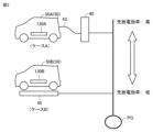
図1は、本実施の形態に従う電力管理システムの概略的な構成を示す図である。図1を参照して、電力管理システム10は、電力系統PGと、サーバ305と、電力リソース群500と、サーバ600と、サーバ700とを含む。
[First embodiment]
1 is a diagram showing a schematic configuration of a power management system according to the present embodiment. Referring to Fig. 1, the
電力系統PGは、送配電設備によって構築される。電力系統PGは、その運用者である電力会社により保守および管理される。 The power grid PG is constructed by power transmission and distribution facilities. The power grid PG is maintained and managed by the electric power company that operates it.
サーバ305は、車両用の有料インフラ310を管理する事業者により運用される。車両用の有料インフラ310は、例えば、高速道路312または駐車場315である。車両が有料インフラ310を利用する場合、サーバ305は、その有料インフラ310の利用料金の支払いを車両のユーザに請求する。
The
電力リソース群500は、各々がバッテリ130を搭載する複数の車両50を含む。各車両50は、電力系統PGと電気的に接続可能に構成されており、分散型電源として機能する電気自動車(BEV:Battery Electric Vehicle)である。
The
各車両50は、車両外部に設けられる電力設備からの電力を用いてバッテリ130を充電する外部充電を実行可能に構成される。
Each
各車両50が外部充電を実行すると、電力系統PGから各車両50に電力が供給されるため、電力系統PGにおける電力負荷が増加する。そのため、各車両50は、外部充電を実行することによって電力負荷の調整に貢献(DRに参加)することができる。各車両50は、DRに参加すると、電力系統PGにおける電力需給バランスへの貢献度に従ってアグリゲータから報酬を得ることができる。
When each
外部充電における充電電力量の増加を車両50に要請する「上げDR」に車両50が参加する場合、増加された電力量だけ電力系統PGにおける電力需要を増加させることができる。上げDRは、電力系統PGにおける電力供給が電力需要よりも多い場合に実施される。
When the
他方、外部充電における充電電力量の低減(節約)を車両50に要請する「下げDR」に車両50が参加する場合、低減された充電電力量だけ電力系統PGにおける電力需要が低減する。下げDRは、電力系統PGにおける電力需要が電力供給よりも多い場合に実施される。この場合、車両50の外部給電(後述)により電力設備45を通じて電力系統PGに電力が供給されてもよい。
On the other hand, when the
サーバ600は、アグリゲータに帰属しており、電力リソース群500を管理するように構成される。アグリゲータは、電力リソース群500を用いて電力系統PGに電力を調達したり、電力系統PGにおける電力負荷を増加または低減させたりする電気事業者である。これにより、アグリゲータは、電力会社から報酬を得ることができる。
The
サーバ600は、処理装置605と、記憶装置620と、通信装置630とを備える。処理装置605は、CPU(Central Processing Unit)などのプロセッサと、ROM(Read Only Memory)およびRAM(Random Access Memory)などのメモリとを含む。記憶装置620は、例えば、処理装置605により実行されるプログラム、ならびに処理装置605により用いられる種々の情報およびデータを格納する。通信装置630は、各種の通信インターフェースである。
The
サーバ600は、サーバ700(後述)から、電力系統PGにおける電力需給バランスの調整要求AREを受信する。調整要求AREは、対象の時間帯において電力需要と電力供給とのいずれが多いかの予測結果を含む。サーバ600は、調整要求AREを受信すると、車両50にDRへの参加を要請する。具体的には、サーバ600は、DR信号S1を各車両50に送信する。
The
DR信号S1は、車両50に下げDRまたはおよび上げDRへの参加を要請するための信号である。DR信号S1は、DRの種類(上げDRまたは下げDRのいずれであるか)と、車両50がDRに参加するように要請される期間(DR期間)とを含む。DR信号S1は、DR期間中に車両50と電力系統PGとの間で授受される電力量(電力系統PGに接続される電力設備から車両50に向けて送電される送電電力量など)と、DRへの参加に対してアグリゲータから車両50のユーザに支払われる報酬(DR報酬)とを示す情報をさらに含む。
The DR signal S1 is a signal for requesting the
サーバ600は、承認信号S11を車両50から受信するように構成される。承認信号S11は、車両50によるDRへの参加が車両50のユーザにより承認された場合に、車両50からサーバ600に送信される。
The
サーバ600が承認信号S11を受信すると、車両50のユーザとアグリゲータとの間で契約が成立する。この契約は、DR期間と、DRの種類、DR期間中の授受電力量と、DR報酬とを示す情報を含む。この契約の内容を示す契約情報は、承認信号S11に含まれており、車両50の記憶装置およびサーバ600の記憶装置620に格納される。
When the
サーバ700は、電力会社に帰属するコンピュータであって、サーバ600と通信可能に構成される。サーバ700は、電力系統PGにおける電力需給バランスを期間(時間帯)ごとに予測し、その予測結果に従って、サーバ600に電力需給バランスの調整要求AREを出力する。
図2は、車両50の構成を示す図である。図2を参照して、車両50は、インレット110と、電圧センサ121,131,141と、電流センサ122,132,142とを備える。車両50は、受電装置123と、バッテリ130と、HMI装置170と、通信装置180と、GPS(Global Positioning System)受信装置181と、ECU150とをさらに備える。
Fig. 2 is a diagram showing the configuration of the
インレット110は、電力スタンド40(後述)から受電するように構成される。電圧センサ121は、インレット110による受電電力の電圧を検出する。電流センサ122は、インレット110による受電電力の電流を検出する。
The
受電装置123は、電力設備45(後述)から非接触で受電したり、電力設備45に非接触で送電したりすることができる。受電装置123は、コイル124を含む。
The
電圧センサ141は、受電装置123による受電電力または送電電力の電圧を検出する。電流センサ142は、受電装置123による受電電力または送電電力の電流を検出する。
The
バッテリ130は、リチウムイオン電池またはニッケル水素電池などの二次電池である。バッテリ130は、電気二重層キャパシタまたはその他の蓄電装置により代替されてもよい。バッテリ130は、インレット110または受電装置123により受電された電力を蓄えるように構成される。
The
電圧センサ131は、バッテリ130の電圧を検出する。電流センサ132は、バッテリ130に対して入出力される電流を検出する。
The
HMI装置170は、入力装置172と、表示装置174とを含む。入力装置172は、ユーザ操作(例えば、車両50の目的地を入力するための操作)を受ける。表示装置174は、各種画面を表示する。
The
通信装置180は、各種機器(例えば、サーバ600またはユーザ端末300)と無線で通信するように構成される。GPS受信装置181は、人工衛星から、車両50の現在地を示す位置情報を取得する。位置情報は、通信装置180を通じてサーバ600に送信されてもよい。
The
ECU150は、プロセッサ151、RAM152、および、記憶装置153を含む。プロセッサ151は、各種の演算処理を実行する。RAM152は、プロセッサ151によって処理されるデータを一時的に記憶する作業用メモリとして機能する。記憶装置153は、プロセッサ151により実行されるプログラム、およびプロセッサ151により用いられる各種情報(例えば、前述の契約情報)を格納する。
The
ECU150は、受電装置123、HMI装置170、および通信装置180などの各種装置を制御する。ECU150は、例えば、電力スタンド40または電力設備45に充電開始要求もしくは充電停止要求を出力することによって車両50の外部充電を制御する。車両50の目的地が設定されている場合、ECU150は、車両50の走行ルートを設定することもできる。
The
車両50が電力スタンド40から電力ケーブル42(後述)を通じて受ける電力を用いた外部充電は、接触充電である。車両50が電力設備45から非接触で受ける電力を用いた外部充電は、非接触充電である。非接触充電は、車両50が給電レーン(後述)を走行している間に実行される走行中充電を含む。
External charging using power that the
電力設備45は、車両50に送電する送電設備として作動可能に構成される。電力設備45は、コイル48と、電圧センサ48Aと、電流センサ48Bと、通信装置46と、制御装置47とを含む。コイル48は、インバータ(図示せず)を通じて商用電源PSに接続される。コイル48は、商用電源PSから供給される電力を用いて車両50に非接触で(より詳細には、電磁界を通じて)給電したり、車両50から非接触で受電したりするように構成される。
The
電圧センサ48Aは、コイル48による送電電力または受電電力の電圧を検出する。電流センサ48Bは、コイル48による送電電力または受電電力の電流を検出する。
The
制御装置47は、DR期間中の電力設備45と車両50との間の電力伝送を制御する。制御装置47は、電圧センサ48Aおよび電流センサ48Bの検出値に従って、DR期間中のコイル48による送電電力量または受電電力量を算出する。通信装置46は、サーバ600と通信するように構成され、例えば、制御装置47により算出された送電電力量および受電電力量をサーバ600に送信する。
The
電力設備45は、地面(例えば、走行レーン)に設置されてもよいし、側壁に設置されてもよい。電力設備45が走行レーンに設置される場合、その走行レーンを給電レーンとも表す。
The
電力スタンド40は、電源回路44と、電圧センサ44Aと、電流センサ44Bと、電力ケーブル42と、コネクタ43と、通信装置48と、制御装置41とを含む。
The
電源回路44は、商用電源PSから供給される電力を変換して、変換後の電力を電力ケーブル42に出力する。
The
電圧センサ44Aは、電源回路44に対して入出力される電圧を検出する。電流センサ44Bは、電源回路44に対して入出力される電流を検出する。
The
電力ケーブル42は、電力スタンド40から車両50へ電力を供給する。電力ケーブル42は、車両50からの電力を電力スタンド40に供給することもできる。
The
コネクタ43は、電力ケーブル42の先端に設けられ、車両50のインレット110に挿入可能に構成される。
The
通信装置48は、サーバ600などの外部機器と通信するように構成される。制御装置41は、通信装置48および電源回路44を制御する。
The
制御装置41は、DR期間中に電力スタンド40から車両50に向けて送電する処理である送電処理を実行可能に構成される。送電処理が実行されると、車両50の外部充電が実行される。制御装置41は、送電処理(外部充電)の完了後、DR期間中の電力スタンド40による送電電力量を、通信装置48を通じてサーバ600に送信する。
The
制御装置41は、DR期間中に電力スタンド40が車両50から受電する処理である受電処理を実行可能にも構成される。受電処理の完了後、電力スタンド40による受電電力量を、通信装置48を通じてサーバ600に送信する。
The
制御装置41は、電力スタンド40から車両50への送電中または電力スタンド40による車両50から受電中の電圧センサ44Aおよび電流センサ44Bの検出値に従って、DR期間中の電力スタンド40の受電電力量または送電電力量を算出する。この受電電力量および送電電力量は、通信装置48によりサーバ600に送信される。
The
ユーザ端末300は、車両50のユーザにより操作される。ユーザ端末300は、入力装置311と、表示装置316と、通信装置318とを含む。入力装置311は、ユーザ入力を受ける。表示装置316は、各種画面を表示する。通信装置318は、ユーザ端末300とは異なる機器(例えば、サーバ600)と通信するように構成される。
The
図3は、車両50が接触充電を実行しているときの状況と、車両50が非接触充電を実行しているときの状況とを示す図である。
Figure 3 shows the situation when the
図3を参照して、車両50が電力スタンド40を用いて接触充電を実行することによってDRに参加する場合(ケースA)、その車両50を車両50A(第1車両)とも表す。バッテリ130Aは、車両50Aに搭載されるバッテリ130である。
Referring to FIG. 3, when the
車両50が電力設備45を用いて非接触充電を実行することによってDRに参加する場合(ケースB)、その車両50を車両50B(第2車両)とも表す。バッテリ130Bは、車両50Bに搭載されるバッテリ130である。
When the
図4は、車両50AがDRに参加する場合にバッテリ130Aに蓄えられる電力量と、車両50BがDRに参加する場合にバッテリ130Bに蓄えられる電力量との違いを示す図である。
Figure 4 shows the difference between the amount of power stored in
図4を参照して、電力スタンド40から車両50Aに対する送電電力量PT1と、電力設備45から車両50Bに対する送電電力量PT2とが等しいケースを想定する。以下の説明において、送電電力量PT1,PT2を特に区別しない場合、これらの送電電力量の各々を送電電力量PTとも表す。
Referring to FIG. 4, a case is assumed in which the amount of power transmitted from the
車両50Aにおいて、送電電力量PTのうちLAの電力量が損失として発生する。その結果、DRに伴って車両50Aのバッテリ130Aに充電される電力量は、PRA(<PT)である。DR期間中の接触充電中の電力スタンド40から車両50Aへの送電効率を送電効率PTE1とも表す。
In the
車両50Bにおいて、送電電力量PTのうちLBの電力量が損失として発生する。非接触充電中の電力設備45から車両50Bへの送電効率を送電効率PTE2とも表す。送電効率PTE2は、送電効率PTE1よりも一般的に低い。そのため、非接触充電において発生する電力損失は、接触充電において発生する電力損失よりも多い(LB>LA)。その結果、DRに伴って車両50Bのバッテリ130Bに充電される電力量は、PRBであり、バッテリ130Aの充電電力量よりも差分ΔPRだけ少ない(PRB=PRA-ΔPR)。
In
上記のように送電電力量PT1,PT2が等しい場合、ケースA,Bのいずれにおいても、送電電力量PTに対応する電力負荷が電力系統PGにおいて発生する。よって、車両50Bは、車両50Aと同程度に電力系統PGの電力需給バランスに貢献をしている。一方で、DRへの参加に伴うバッテリ130の充電電力量という観点からは、車両50Bは、車両50Aに比べて不利である。
When the transmission power amounts PT1 and PT2 are equal as described above, in both cases A and B, a power load corresponding to the transmission power amount PT occurs in the power system PG. Therefore,
図5は、車両50がDRに参加するときに得る利益という観点から、接触充電と非接触充電との違いを説明するための図である。この例は、後述のサーバ600による処理が実行されない場合の比較例を示す。
Figure 5 is a diagram for explaining the difference between contact charging and non-contact charging from the viewpoint of the benefits that a
図5を参照して、グラフ220は、比較例においてアグリゲータから車両50A,50Bに与えられる報酬と、車両50A,50BがDRに参加するときにかかる電力料金とを示す。
Referring to FIG. 5,
車両50AのDR報酬RWAおよび車両50BのDR報酬RWBは、それぞれ、車両50A,50Bによる、電力系統PGにおける需給バランスの調整への貢献度に従って決定される。例えば、送電電力量PTが増加するほど、電力系統PGにおける電力負荷が増加する。そのため、この実施の形態1では、車両50A,50BのDR報酬は、DR期間中の送電電力量PTに従って決定される(例えば、送電電力量PTが増加するほど多くなる)。
The DR remuneration RWA of
送電電力量PT1に対する、DR報酬RWAの単価をDR報酬単価UPRR1とも表す。送電電力量PT2に対する、DR報酬RWBの単価をDR報酬単価UPRR2とも表す。この例では、DR報酬単価UPRR1,UPRR2は、いずれもUPRR10であるものとする。電力系統PGの電力料金単価を、電力コスト単価UPRPとも表す。 The unit price of DR remuneration RWA for the amount of transmitted power PT1 is also referred to as the DR remuneration unit price UPRR1. The unit price of DR remuneration RWB for the amount of transmitted power PT2 is also referred to as the DR remuneration unit price UPRR2. In this example, both the DR remuneration unit prices UPRR1 and UPRR2 are UPRR10. The power rate unit price of the power system PG is also referred to as the power cost unit price UPRP.
DR報酬RWAは、送電電力量PT1(PT)に従って決定され、RW0(=UPRR10×PT1)である。車両50AがDRに参加するときの接触充電に伴って車両50Aにかかる電力コストPCAは、電力コスト単価UPRPと、送電電力量PT1とに従って決定される(PCA=UPRP×PT1)。よって、車両50AがDRに参加するときに得るDR利益PAは、PA0(=RW0-PCA)である。
The DR reward RWA is determined according to the amount of transmitted power PT1 (PT) and is RW0 (= UPRR10 x PT1). The power cost PCA incurred by
同様に、DR報酬RWBは、送電電力量PT2(PT)に従って決定され、RW0(=UPRR10×PT2=RWA)である。車両50BがDRに参加するときの非接触充電に伴って車両50Bにかかる電力コストPCB0は、送電電力量PT2と、電力コスト単価UPRPとに従って決定される(PCB0=UPRP×PT2)。この例では、DR期間中の車両50Bの電力コストPCB0は、車両50Aの電力コストPCAに等しい。
Similarly, the DR reward RWB is determined according to the amount of transmitted power PT2 (PT) and is RW0 (=UPRR10 x PT2 = RWA). The power cost PCB0 incurred by
DR期間中、バッテリ130Bの充電電力量は、バッテリ130Aの充電電力量よりも少ない(図4)。よって、DR期間終了後にバッテリ130Bの蓄電量が不十分である場合(例えば、車両50Bのユーザがバッテリ130Bの満充電を望む場合)、車両50Bは、非接触充電を余分に実行することを要することがある。この例では、差分ΔPR(図4)の電力量をバッテリ130Bに充電するために差分ΔPCの電力量が電力設備45から車両50Bに向けて余分に送電されることを要するものとする。差分ΔPCは、差分ΔPRと、送電効率PTE1,PTE2(図4)とに依存する。
During the DR period, the amount of charging power of the
差分ΔPCの電力量が電力設備45から車両50Bに向けて送電されると、余分な電力コストΔPAB(=UPRP×ΔPC)が非接触充電に伴って車両50Bのユーザにかかる。その結果、車両50Bにかかるトータルの電力コストPCBは、車両50Aの電力コストPCAよりも多い(PCB=PCA+ΔPAB)。
When the amount of power difference ΔPC is transmitted from the
グラフ230は、比較例において車両50A,50BがDRに参加するときに得るDR利益を示す。DR利益PAは、DR報酬RWAから電力コストPCAを差し引くことによって得られる。車両50BのDR利益PBは、DR報酬RWBから電力コストPCBを差し引くことによって得られる。この例では、DR報酬RWBがDR報酬RWAに等しいため(グラフ220)、車両50BのDR利益PB(PB0)は、車両50AのDR利益PA(PA0)よりもこれらの利益の差分ΔP(=ΔPAB)だけ少ない。
以上から、車両50Bが車両50Aと比較して不利益を被り、車両50Bのユーザは、車両50Aのユーザと比較して損をするために不公平であると感じる可能性がある。車両50BのユーザがDRに参加する意欲を不公平感のために失うと、非接触充電によりDRに参加する電力リソースが減少する可能性がある。あるいは、車両50Bが非接触充電(例えば、走行中充電)によりDRに参加することが要望される期間に車両50Bが非接触充電を実行しない可能性がある。そして、その期間終了後に、車両50Bが非接触充電に代えて接触充電を実行する状況さえ想定され得る。このような状況は、電力需給バランスが適切に調整されない事態を引き起こし得る。
From the above,
実施の形態1に従うサーバ600は、上記のような問題に対処するための構成を備える。具体的には、通信装置630は、DRに参加している車両50の外部充電中に電力設備から送電される送電電力量PTを取得する。各車両50がDRに参加する場合に、処理装置605は、送電電力量PTに従って基準報酬を設定する。基準報酬は、アグリゲータから各車両50に与えられる報酬の基準である。基準報酬の設定方法の詳細については、後述する。
The
車両50AがDRに参加する場合に、処理装置605は、アグリゲータから車両50Aに与えられるDR報酬RWA(第1報酬)が車両50Aの基準報酬になるようにDR報酬RWAを決定する。一方、車両50BがDRに参加する場合に、処理装置605は、アグリゲータから車両50Bに与えられるDR報酬RWB(第2報酬)が車両50Bの基準報酬よりも多くなるようにDR報酬RWBを決定する。
When
このような構成とすることにより、DR報酬RWAは車両50Aの基準報酬であるのに対し、DR報酬RWBは車両50Bの基準報酬よりも多いので、車両50Bは、車両50Aよりも報酬の観点で恩恵を受けることができる。そのため、車両50Bが車両50Aと比べて不利益を被る状況を改善することができる。
By configuring in this way, the DR reward RWA is the base reward for
この実施の形態1では、処理装置605は、送電電力量PT1と、DR報酬単価UPRR1(第1単価)とに従ってDR報酬RWAを決定する。処理装置605は、送電電力量PT2と、DR報酬単価UPRR2(第2単価)とに従ってDR報酬RWBを決定する。処理装置605は、DR報酬単価UPRR2がDR報酬単価UPRR1よりも高くなるようにDR報酬単価UPRR1およびDR報酬単価UPRR2を決定する。
In this
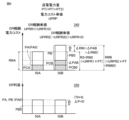
図6は、実施の形態1においてDR報酬RWBが基準報酬よりも多くなるように決定されることを説明するための図である。
Figure 6 is a diagram to explain how the DR reward RWB is determined to be greater than the base reward in
図6を参照して、グラフ240は、実施の形態1における、DR報酬RWA,RWBを示す。グラフ240は、DR報酬RWBが比較例(図5)の場合よりも差分ΔRWだけ多い点において、グラフ220とは異なる。より詳細には、グラフ240は、DR報酬単価UPRR2(=UPRR20)が比較例の場合よりも高い点においてグラフ220とは異なる(UPRR20>UPRR10)。その他の点について、グラフ240は、グラフ220と基本的に同様である。
Referring to FIG. 6,
この実施の形態1では、車両50A,50Bについて、基準報酬RSが設定される。車両50A,50Bの基準報酬RSは、送電電力量PTに従って設定され(例えば、送電電力量PTが大きいほど多い)、この例では、いずれもRW0である。
In this
車両50AのDR報酬RWAは、車両50Aの基準報酬RSに等しくなるように決定される(RWA=RS)。この例では、車両50AのDR報酬単価UPRR1(=UPRR10)は、比較的の場合と等しい。
The DR remuneration RWA of
他方、車両50BのDR報酬RWBは、車両50Bの基準報酬RSよりも差分ΔRW(=ΔPAB)だけ多くなるように決定される(RWB=RWB0=RS+ΔRW)。より詳細には、DR報酬単価UPRR2が比較例の場合よりも高くなるように設定される(UPRR20>UPRR10)。上記のようにDR報酬RWBが車両50Bの基準報酬RSよりも多く決定されることは、別の観点からは、比較例の場合と比べて差分ΔRWの金額が車両50Bに補填される(追加報酬として支払われる)ことに等しい。
On the other hand, the DR remuneration RWB of
その結果、非接触充電中の電力損失に伴う余分な電力コストΔPABが車両50Bにかかったとしても、電力コストΔPABと、差分ΔRWの追加報酬とが相殺される。
As a result, even if
グラフ250は、実施の形態1における、DR利益PA,PBを示す。実施の形態1において、車両50BのDR利益PBは、比較例の場合(図5のPB0)よりも多い。その結果、DR利益PA,PBの差分ΔPは、比較例(図5)の場合よりも小さくなる。この例では、差分ΔPが0になるようにDR報酬RWA,RWBが決定される。これにより、車両50A,50Bの間の不公平が解消される。
差分ΔPがしきい値TH未満になるように、DR報酬RWA,RWBが決定されてもよい。この場合においても、DR利益PA,PBが乖離する事態を回避することができる。その結果、比較例の場合よりも不公平を低減しつつ、DR報酬RWA,RWBを適切に決定することができる。上記のしきい値THは、0以上の値として適宜予め定められるが、実質的に0であることが好ましい。 The DR rewards RWA and RWB may be determined so that the difference ΔP is less than the threshold value TH. Even in this case, it is possible to avoid a situation in which the DR profits PA and PB diverge. As a result, it is possible to appropriately determine the DR rewards RWA and RWB while reducing unfairness more than in the comparative example. The above threshold value TH is appropriately predetermined as a value equal to or greater than 0, but it is preferable that it is substantially 0.
以上から、実施の形態1では、車両50BのユーザがDRに参加する意欲を不公平感のために失う事態を回避することができる。その結果、DRに参加する車両50Bが減少するのを抑制して電力需給バランスの調整に貢献することができる。
As described above, in the first embodiment, it is possible to avoid a situation in which the user of
図7は、サーバ600の記憶装置620に記憶されるデータの一例を示す図である。図7を参照して、記憶装置620は、調整計画情報650と、電力コスト単価情報670と、リソース情報665と、送電計画情報666と、DR報酬単価/DR報酬情報668とを記憶している。
Figure 7 is a diagram showing an example of data stored in the
調整計画情報650は、アグリゲータと電力会社との間の事前の契約に従って決定された、電力需給バランスの調整計画を示す。調整計画情報650は、調整要求電力量ARPと、調整報酬ARと、調整報酬単価ARUPと、トータル報酬金額TRAと、調整利益APRとをDR期間ごとに示す。各DR期間の長さは、例えば30分であるが、限定されない。
The
調整要求電力量ARPは、電力系統PGにおいて調整(調達または増加もしくは低減)されるように電力会社がアグリゲータに要求する電力量を示す。調整報酬ARは、アグリゲータが調整要求電力量ARPを首尾よく調整した場合に電力会社から受ける報酬を示す。調整報酬単価ARUPは、調整要求電力量ARPに対する調整報酬ARの単価を示す。 The adjustment requested power amount ARP indicates the amount of power that the power company requests the aggregator to adjust (procure or increase or decrease) in the power system PG. The adjustment remuneration AR indicates the remuneration that the aggregator receives from the power company when it successfully adjusts the adjustment requested power amount ARP. The adjustment remuneration unit price ARUP indicates the unit price of the adjustment remuneration AR for the adjustment requested power amount ARP.
トータル報酬金額(トータル分配額)TRAは、調整利益APRのうちアグリゲータから各車両50に与えられる(分配される)報酬の合計を示す。少なくとも1つの車両50Aおよび少なくとも1つの車両50BがDRに参加する場合、トータル報酬金額TRAは、各車両50AのDR報酬RWAの合計と、各車両50Bの報酬DRBの合計との加算値である。以下、説明の簡略化のため、トータル報酬金額TRAが、一つの車両50Aの報酬RWAと、一つの車両50Bの報酬RWBとの合計であるケースを代表的に説明する。
The total remuneration amount (total distribution amount) TRA indicates the sum of the remuneration given (distributed) by the aggregator to each
調整利益APRは、アグリゲータが首尾よく電力調整を達成したときに得る利益を示す。調整利益APRは、調整報酬ARとトータル報酬金額TRAとの差分である(APR=AR-TRA)。電力コスト単価情報670は、電力系統PGの電力コスト単価UPRPを示す。
The adjusted profit APR indicates the profit that the aggregator obtains when it successfully achieves power adjustment. The adjusted profit APR is the difference between the adjusted remuneration AR and the total remuneration amount TRA (APR=AR-TRA). The power cost
リソース情報665は、各電力リソース(この例では、各車両50)の外部充電の方式をリソースIDごとに示す。リソースIDは、電力リソースを識別するための番号である。さらに、リソース情報665は、各電力リソースがDRに参加可能であるか否かと、DR期間中の外部充電の方式を期間ごとに示す。リソース情報665は、アグリゲータと各電力リソースのユーザとの間で行われた契約の内容に従って決定される。
The
R1またはR2のリソースIDを有する車両は、接触充電および非接触充電の両方を実行することができる。この例では、R1のIDを有する車両が車両50A(図3)に対応し、R2のIDを有する車両が車両50Bに対応するものとする。
A vehicle with a resource ID of R1 or R2 can perform both contact charging and contactless charging. In this example, the vehicle with an ID of R1 corresponds to
送電計画情報666は、送電電力量PTと、電力設備から車両への送電方式とをリソースIDおよびDR期間ごとに示す。この例では、PE1のIDを有する電力設備が電力スタンド40に対応し、PE2のIDを有する電力設備が電力設備45に対応するものとする。
The power
DR報酬単価/DR報酬情報668は、電力リソースのDR報酬の単価およびDR報酬をリソースIDおよびDR期間ごとに示す。DR報酬単価/DR報酬情報668は、送電計画情報666の送電電力量PTに依存する。例えば、R1のリソースIDを有する車両50Aについて、期間P1中のDR報酬RWAは、prA1(=uprA1×a1)である。
The DR remuneration unit price/
図8は、実施の形態1に従うサーバ600の機能を説明するための機能ブロック図である。以下の説明において、図4から図7を適宜参照する。
Figure 8 is a functional block diagram for explaining the functions of
図8を参照して、サーバ600は、充電電力量取得部400と、余分電力コスト算出部404と、送電電力量取得部406と、DR報酬算出部405と、電力コスト算出部408とを備える。サーバ600は、DR利益算出部410と、DR利益差算出部425と、判定部430と、基準報酬設定部435と、補填額設定部440と、DR報酬単価設定部445とをさらに備える。サーバ600は、DR報酬決定部450と、トータル報酬金額設定部460と、送電計画設定部470と、送電計画送信部475と、充電計画送信部476と、DR期間開始報知部488とをさらに備える。
Referring to FIG. 8, the
充電電力量取得部400、送電電力量取得部406、送電計画送信部475、充電計画送信部476、およびDR期間開始報知部488の機能は、通信装置630が処理装置605からの指令に従って作動することによって達成される。他の機能は、処理装置605が作動することによって達成される。
The functions of the charging energy
充電電力量取得部400は、DR期間終了後に、車両50A,50Bから、それぞれ、信号SA1,SB1を通信によって取得する。信号SA1は、DR期間中の車両50Aのバッテリ130Aの充電電力量を示す。信号SB1は、DR期間中の車両50Bのバッテリ130Bの充電電力量を示す。
After the DR period ends, the charging energy
余分電力コスト算出部404は、バッテリ130A,130Bの充電電力量の差分ΔPR(図4)を電力設備45の送電効率PTE2により除算することによって、差分ΔPCを算出する。差分ΔPCは、電力設備45から車両50Bに向けて余分に送電されることを要する電力量である。余分電力コスト算出部404は、電力コスト単価UPRPと差分ΔPCとに従って、車両50Bの余分の電力コストΔPAB(図5)を算出する。送電効率PTE1,PTE2は、DR期間の終了に伴って処理装置605により算出され、記憶装置620に格納される。
The excess power
送電電力量取得部406は、DR期間終了後に、電力スタンド40および電力設備45から、それぞれ、信号SA2,SB2を通信により取得する。信号SA2は、DR期間中の送電電力量PT1を示す。送電電力量PT1は、電力スタンド40の電圧センサ44Aおよび電流センサ44Bの検出値に従って制御装置41により算出される。信号SB2は、DR期間中の送電電力量PT2を示す。送電電力量PT2は、電力設備45の電圧センサ48Aおよび電流センサ48Bの検出値に従って制御装置47により算出される。
After the DR period ends, the transmitted power
DR報酬算出部405は、送電電力量取得部406による取得結果に従って、DR報酬RWA,RWBの仮の値を算出する。具体的には、DR報酬算出部405は、DR報酬単価/DR報酬情報668(図7)におけるDR報酬単価UPRR1(この例では、図6のUPRR10であるものとする)と、送電電力量PT1とに従って、DR報酬RWAの仮の値を算出する。このように算出された車両50Aの仮のDR報酬を仮第1報酬とも表す。仮第1報酬は、例えば、RW0である。そして、DR報酬算出部405は、DR報酬単価/DR報酬情報668におけるDR報酬単価UPRR2がDR報酬単価UPRR1に等しいデフォルト値であるものとして、送電電力量PT2と、DR報酬単価UPRR2とに従って、DR報酬RWBの仮の値を算出する。このように算出された車両50Bの仮のDR報酬を仮第2報酬とも表す。仮第2報酬は、例えば、仮第1報酬に等しいRW0である。DR報酬単価/DR報酬情報668におけるDR報酬単価UPRR2は、デフォルト値から後ほど変更され得る(後述)。
The DR
電力コスト算出部408は、DR期間中の車両50A,50Bの電力コストを算出する。具体的には、電力コスト算出部408は、送電電力量PT1と、電力コスト単価情報670(図8)とに従って、電力コストPCAを算出する。同様に、電力コスト算出部408は、送電電力量PT2と、電力コスト単価情報670とに従って、電力コストPCB0を算出する。さらに、電力コスト算出部408は、電力コストPCB0と、車両50Bの余分の電力コストΔPABとに従って電力コストPCBを算出する。
The power
DR利益算出部410は、車両50Aの仮DR利益(仮第1利益)と、車両50Bの仮DR利益(仮第2利益)とを算出する。具体的には、DR利益算出部410は、仮第1報酬から電力コストPCAを差し引くことによって仮第1利益を算出する。同様に、DR利益算出部410は、仮第2報酬から電力コストPCBを差し引くことによって仮第2利益を算出する。
The DR
DR利益差算出部425は、仮第1利益と仮第2利益との差分である仮利益差を算出する。
The DR profit
判定部430は、DR報酬単価UPRR2がデフォルト値から変更されることを要するか否かを、仮利益差に従って判定する。具体的には、判定部430は、仮利益差がしきい値TH以上であるか否かを判定する。
The
仮利益差がしきい値TH未満である場合、車両50Aと車両50Bとの間の不公平が無いか、または実用的な観点から問題が無いほど小さい。この場合、仮第1利益および仮第2利益は、それぞれ、利益RWAおよび利益RWBとして決定される。
If the provisional profit difference is less than the threshold value TH, there is no unfairness between
他方、仮利益差がしきい値TH以上である場合、不公平が無視できないほど仮第2利益が仮第1利益よりも少ない。よって、仮第1利益および仮第2利益が、それぞれ、利益RWAおよび利益RWBとして決定されることは、好ましくない(例えば、図5のグラフ230)。
On the other hand, if the provisional profit difference is equal to or greater than the threshold value TH, the provisional second profit is less than the provisional first profit to the extent that unfairness cannot be ignored. Therefore, it is not preferable to determine the provisional first profit and the provisional second profit as the profit RWA and the profit RWB, respectively (for example,
判定部430は、送電電力量PT1に対する仮第1利益の比率(仮第1利益率)と、送電電力量PT2に対する仮第2利益の比率(仮第2利益率)との差分がしきい率以上であるか否かを判定してもよい。しきい率は、実質的に0(例えば、0以上かつ0.1未満)となるように適宜予め定められることが好ましい。これにより、送電電力量PT1,PT2が異なる場合においても、不公平の有無を判定することができる。
The
仮利益差がしきい値TH以上である場合、基準報酬設定部435は、車両50A,50Bの基準報酬RSを送電電力量PTに従って設定する。実施の形態1では、基準報酬設定部435は、送電電力量PTと、DR報酬単価UPRR1(図6のUPRR10)との乗算値として、車両50A,50Bの基準報酬RSを算出する。この例では、車両50A,50Bの基準報酬RSは、いずれも、図6のRW0である。
If the provisional profit difference is equal to or greater than the threshold value TH, the base
補填額設定部440は、利益PRA,PRBの差分ΔPがしきい値TH未満になるように、車両50Bへの補填額を設定する。この例では、補填額設定部440は、余分の電力コストΔPAB(図6)と差分ΔRWの追加報酬とが相殺されるように上記の補填額を設定する。この補填額は、電力コストΔPABに等しいことが好ましいが、電力コストΔPAB未満であってもよい。
The compensation
DR報酬単価設定部445は、DR報酬単価UPRR1,UPRR2が上記の補填額を反映するように、これらの単価を設定する。この例では、DR報酬単価設定部445は、DR報酬単価UPRR1をUPRR10(図6)に保つ。他方、DR報酬単価設定部445は、DR報酬単価/DR報酬情報668を書き換えることによって、DR報酬単価UPRR2をデフォルト値(UPRR10)よりも高いUPRR20に設定する。
The DR remuneration unit
その後、DR報酬算出部405は、上記のように設定されたDR報酬単価(書き換え後のDR報酬単価/DR報酬情報668に従って、DR報酬RWA,RWBを算出する。この例では、DR報酬RWAは、仮第1報酬に等しいRW0に保たれる。他方、DR報酬RWBは、仮第2報酬であるRW0よりも差分ΔRWだけ増加する。
Then, the DR
DR利益算出部410は、このように算出されたDR報酬RWAと電力コストPCAとに従って、DR利益PA(図6)を算出する。同様に、DR利益算出部410は、上記のように算出されたDR報酬RWBと電力コストPCBとに従って、DR利益PBを算出する。
The DR
DR利益差算出部425は、DR利益PA,PBの差分ΔPを算出する。この例では、差分ΔPがしきい値TH未満となるようにDR報酬単価/DR報酬情報668が既に書き換えられている。
The DR profit
判定部430は、差分ΔPがしきい値TH以上であるか否かを判定し、差分ΔPがしきい値TH未満であると判定する。
The
DR報酬決定部450は、書き換え後のDR報酬単価/DR報酬情報668に従って算出された、DR報酬RWA,RWBを、それぞれ、車両50A,50BのDR報酬として決定する。決定されたDR報酬RWA,RWBは、車両50A,50Bのユーザの銀行口座を管理するサーバ(図示せず)に送信される。
The DR
トータル報酬金額設定部460は、報酬RWA,RWBの決定結果に従って、トータル報酬金額TRA(図7)を設定する。この例では、説明の簡略化のため、トータル報酬金額TRAは、報酬RWA,RWBの合計であるものとする。トータル報酬金額設定部460が、上記のようにトータル報酬金額TRAを設定すると、DR報酬RWBの増加に伴ってトータル報酬金額TRAが増加する。トータル報酬金額設定部460は、トータル報酬金額TRAが増加するように調整計画情報650を書き換える。これにより、調整利益APR(図6)が調整計画情報650の書き換え前と比べて減少する(更新される)。
The total remuneration
送電計画設定部470は、DR期間中の電力スタンド40および電力設備45の送電計画を、調整計画情報650と、リソース情報665とに従って設定する。具体的には、送電計画設定部470は、複数の電力リソースの中から、対象の期間中にDRに参加することができる電力リソース(例えば、車両50A,50B)をリソース情報665に従って選択する。送電計画設定部470は、調整計画情報650により定められた調整要求電力量ARPに従って、送電計画情報666を設定する。
The power transmission
送電計画送信部475は、送電計画情報666を電力設備(電力スタンド40および電力設備45)に送信する。電力スタンド40および電力設備45は、送信された送電計画情報666に従って、それぞれ、車両50A,50Bに向けてDR期間中に送電電力量PTを送電する。
The power transmission
充電計画送信部476は、DR期間中の外部充電の計画を車両50A,50Bに送信する。この計画は、DR期間の開始時刻および終了時刻を示す情報を含む。この計画は、送電計画情報666に従って作成される。
The charging
DR期間開始報知部488は、車両50A,50BのDR期間の開始時刻が到来すると車両50A,50Bのユーザに報知を行うための処理を実行する。具体的には、DR期間開始報知部488は、上記の開始時刻の到来を報知する報知信号S31A,S31Bを、それぞれ、車両50A,50Bに送信する。
The DR period start
例えば、車両50Bは、走行中充電を実行することによってDRに参加するものとする。DR期間の開始時刻が到来するまで、車両50Bが、給電レーンとは異なる走行レーン(例えば、給電レーンに隣接しており、かつ、給電機能を有しない走行レーン)を走行している場合、報知信号S31Bは、車両50Bが給電レーンを走行するように車両50Bのユーザに促す。
For example,
具体的には、車両50BのECU150は、報知信号S31Bに受信に応答して、HMI装置170の表示装置174に上記の報知をユーザに行うための報知画面を表示する。ECU150は、ユーザ端末300の表示装置316に報知画面が表示されるように通信装置180を制御してもよい。このように報知が行われると、アグリゲータは、車両50BをDRに確実に参加させることができる。
Specifically, in response to receiving the notification signal S31B, the
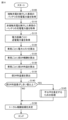
図9は、実施の形態1において、対象のDR期間が到来する前にサーバ600の処理装置605により実行される処理の一例を示すフローチャートである。このフローチャートの処理は、対象のDR期間中の電力系統PGにおいて電力供給が電力需給よりも多いことを示す調整要求ARE(図1)をサーバ600が受信すると開始される。
Figure 9 is a flowchart showing an example of processing executed by the
図9を参照して、処理装置605は、対象の期間中にDRに参加することができる電力リソース(この例では、車両50A,50B)を、リソース情報665に従って選択する(ステップS20)。
Referring to FIG. 9, the
次いで、処理装置605は、調整計画情報650により定められた調整要求電力量ARPに従って、送電計画情報666を設定する(ステップS25)。
Next, the
次いで、処理装置605は、車両50A,50Bに外部充電の計画を送信し(ステップS30)、電力設備(電力スタンド40および電力設備45)に送電計画情報666を送信する(ステップS40)。
Next, the
図10は、実施の形態1において、対象のDR期間が終了した後に処理装置605により実行される処理の一例を示すフローチャートである。
Figure 10 is a flowchart showing an example of processing executed by the
図10を参照して、処理装置605は、DRのために接触充電を実行した車両50Aのバッテリ130Aの充電電力量を、通信装置630を通じて車両50Aから取得する(ステップS105)。
Referring to FIG. 10, the
次いで、処理装置605は、DRのために非接触充電を実行した車両50Bのバッテリ130Bの充電電力量を、通信装置630を通じて車両50Bから取得する(ステップS110)。
Next, the
次いで、処理装置605は、DRのために用いられた電力設備ごとの(この例では、電力スタンド40および電力設備45の)送電電力量PTを取得する(ステップS115)。
Next, the
次いで、処理装置605は、DRに参加した車両ごとに電力コストを算出する(ステップS120)。この例では、処理装置605は、電力コストPCA,PCB(図6)を算出する。電力コストPCBは、DRに伴う電力コストPCB0と、余分の電力コストΔPABとを含む。
Next, the
次いで、処理装置605は、車両ごとの仮DR報酬を算出する(ステップS125)。この例では、処理装置605は、車両50Aの仮第1報酬と、車両50Bの仮第2報酬とを算出する。
Next, the
次いで、処理装置605は、車両ごとの仮DR利益を算出する(ステップS130)。この例では、処理装置605は、車両50Aの仮第1利益と、車両50Bの仮第2利益とを算出する。
Next, the
次いで、処理装置605は、車両50Aの仮第1利益と車両50Bの仮第2利益との差分を算出することによって、車両50A,50Bの仮利益差を算出する(ステップS135)。
Next, the
次いで、処理装置605は、仮DR利益差がしきい値TH以上であるか否かを判定する(ステップS140)。仮DR利益差がしきい値TH未満である場合(ステップS140においてNO)、処理装置605は、ステップS150に処理を進める。他方、仮DR利益差がしきい値TH以上である場合(ステップS140においてYES)、処理装置605は、車両50Aと車両50Bとの間の不公平を是正するための処理を実行する(ステップS145)。
Next, the
図11は、不公平を是正するための処理(図10のステップS145)の詳細を説明するためのフローチャートである。 Figure 11 is a flowchart explaining the details of the process for correcting unfairness (step S145 in Figure 10).
図11を参照して、処理装置605は、車両50A,50Bについて、送電電力量PTに従って基準報酬RSを算出する(ステップS1451)。この例では、送電電力量PT1と、送電電力量PT2とが等しいものとし、車両50A,50Bの基準報酬RSは、いずれもRW0(図6)である。
Referring to FIG. 11, the
次いで、処理装置605は、車両50Bへの補填額として与えられる報酬(例えば、図6の差分ΔRWの追加報酬)を設定する(ステップS1452)。
Next, the
次いで、処理装置605は、DR報酬単価UPRR1,UPRR2が上記の補填額を反映するように、これらのDR報酬単価を設定する(ステップS1455)。具体的には、処理装置605は、図6の差分ΔPがしきい値TH未満になるように、これらのDR報酬単価を設定する。
Next, the
次いで、処理装置605は、ステップS1455において設定されたDR報酬単価UPRR1,UPRR2に従って、DR報酬RWA(第1報酬)と、DR報酬RWB(第2報酬)とを決定する(ステップS1457)。この例では、DR報酬RWAは、RW0(図6)であり、DR報酬RWBは、RW0+ΔRWである。その後、処理は、ステップS150(図10)に進む。
Next, the
図10を再び参照して、処理装置605は、DR報酬RWA,RWBの決定結果に従って、トータル報酬金額TRAを決定する(ステップS150)。その後、一連の処理が終了する。
Referring again to FIG. 10, the
図12は、車両50のECU150により実行される処理の一例を示すフローチャートである。このフローチャートの処理は、車両50の走行ルートが設定されている場合に車両50が承認信号S11(図1)をサーバ600に送信すると開始される。
Figure 12 is a flowchart showing an example of processing executed by the
次いで、ECU150は、DR期間が到来したか否かを判定する(ステップS215)。ECU150は、記憶装置153に記憶された契約情報に従って、この判定処理を実行する。DR期間が未だ到来していない場合(ステップS215においてNO)、ECU150は、この期間が到来するまでこの判定処理を実行する。他方、DR期間が到来した場合(ステップS215においてYES)、ECU150は、ステップS217に処理を進める。
Next, the
次いで、ECU150は、DR期間の到来を車両50のユーザに報知する(ステップS217)。例えば、ECU150が車両50Bに搭載されており、かつ、車両50Bが走行中充電を実行することによりDRに参加する場合には、ECU150は、表示装置174に前述の報知画面を表示する。
Next, the
次いで、ECU150は、車両50の外部充電可能条件が満たされているか否かを判定する(ステップS215)。車両50が車両50Aである場合、外部充電可能条件は、インレット110にコネクタ43が挿入されていることである。車両50が車両50Bである場合、外部充電可能条件は、車両50と電力設備45との距離が、車両50が電力設備45から受電することができるしきい値距離未満である(例えば、車両50が給電レーンを走行している)ことである。
Next, the
外部充電可能条件が満たされていない場合(ステップS215においてNO)、ECU150は、この条件が満たされるまで上記の判定処理を実行する。他方、充電可能条件が満たされている場合(ステップS215においてYES)、ECU150は、ステップS220に処理を進める。
If the external chargeable condition is not met (NO in step S215), the
次いで、ECU150は、車両50がDRに参加するために外部充電(接触充電または非接触充電)を実行する(ステップS220)。この外部充電は、DR期間が終了するまで継続する。
[実施の形態1の変形例1]
前述の実施の形態1では、処理装置605は、報酬RWAが保たれた状態で報酬RWBが増加するように報酬RWA,RWBを決定するものとした(図6)。その結果、アグリゲータから各車両50へのトータル報酬金額TRA(図7)が増加する。
Next,
[First Modification of First Embodiment]
In the first embodiment described above, the
この変形例1では、処理装置605は、調整計画情報650のトータル報酬金額TRAが一定に保たれるように報酬RWAおよび報酬RWBを決定する。
In this variant example 1, the
その結果、上記のトータル報酬金額TRAが増大する事態が回避される。よって、アグリゲータは、トータル報酬金額TRAの増大に伴って調整利益APR(図7)が減少する事態を回避しつつ、トータル報酬金額TRAを車両50A,50Bに適切に分配することができる。これにより、アグリゲータビジネスへの新規参入事業者が減少する事態を回避することによって、電力需給バランスの調整に貢献することができる。
As a result, the total remuneration amount TRA is prevented from increasing. Therefore, the aggregator can appropriately distribute the total remuneration amount TRA to the
図13は、この変形例1における、車両50A,50BのDR報酬の決定方法を説明するための図である。
Figure 13 is a diagram illustrating the method for determining the DR rewards for
図13を参照して、グラフ260は、この変形例における車両50A,50Bの基準報酬RSと、DR報酬RWA,RWBとを示す。この例では、車両50A,50Bの基準報酬RSは、いずれも、実施の形態1の基準報酬(図6のRW0)よりも小さい。
Referring to FIG. 13,
DR報酬単価UPRR1は、前述の実施の形態1の場合よりも低く設定される(UPRR15<UPRR10)。DR報酬RWAは、車両50Aの基準報酬RS(=UPRR15×PT)に等しい一方で、実施の形態1のRW0よりも少ない。
The DR remuneration unit price UPRR1 is set lower than in the first embodiment described above (UPRR15<UPRR10). The DR remuneration RWA is equal to the base remuneration RS (=UPRR15×PT) for
DR報酬RWBは、車両50Bの基準報酬RSよりも差分ΔRWだけ多くなるように決定される一方で、実施の形態1(図6)の場合のRWB0よりも差分ΔRWWだけ低い。この例では、DR報酬単価UPRR2は、前述の実施の形態1の場合よりも低く設定される一方で、DR報酬単価UPRR1よりは高く決定される(UPRR15<UPRR2=UPRR25<UPRR20)。
The DR remuneration RWB is determined to be greater than the base remuneration RS of
グラフ270は、この変形例1において車両50A,50BがDRに参加するときに得るDR利益を示す。DR利益RWAは、実施の形態1の場合(図6のPA0)よりもΔPAだけ少なくなるように決定される。一方、DR利益PBは、この例では、比較例のDR利益PB(PB0)よりもΔPAだけ多い。すなわち、車両50AのDR利益(PA0)の一部(ΔPA)がDR利益PBに補填されている。
図14は、この変形例1において、対象のDR期間が終了した後に処理装置605により実行される処理の一例を示すフローチャートである。この例では、トータル報酬金額(トータル分配額)TRAが一定に保たれる。
Figure 14 is a flow chart showing an example of processing executed by the
図14を参照して、このフローチャートは、トータル報酬金額を決定する処理(ステップS150)が実行されない点において、前述の実施の形態1のフローチャート(図10)とは異なる。ステップS205~ステップS245の処理は、それぞれ、図6のステップS105~ステップS145の処理と同様である。 Referring to FIG. 14, this flowchart differs from the flowchart of the first embodiment (FIG. 10) in that the process of determining the total remuneration amount (step S150) is not executed. The processes of steps S205 to S245 are similar to the processes of steps S105 to S145 in FIG. 6, respectively.
ステップS245において、トータル報酬金額TRAが保たれるように、DR報酬RWA,RWB(より詳細には、DR報酬単価UPRR1,UPRR2)が決定される。具体的には、DR報酬RWA,RWBは、車両50AのDR利益の一部がDR利益PBに補填されるように決定される(図13参照)。
[実施の形態1の変形例2]
車両50Aおよび車両50Bが車両用の有料インフラ310を利用する場合に、処理装置605は、車両50Bが車両50Aよりも有料インフラ310を安く利用できるように報酬RWAおよび報酬RWBを決定してもよい。
In step S245, the DR remunerations RWA and RWB (more specifically, the DR remuneration unit prices UPRR1 and UPRR2) are determined so that the total remuneration amount TRA is maintained. Specifically, the DR remunerations RWA and RWB are determined so that a part of the DR profit of the
[Modification 2 of the First Embodiment]
When the
例えば、処理装置605は、有料インフラ310を管理する事業者のサーバ305(図1)に、車両50Bの利用料金を車両50Aの利用料金よりも差分ΔRW(図6)だけ割引するように要求を出力する。この例では、車両50Bがその割引額で有料インフラ310を利用することをサーバ305が許可するものとする。その後、処理装置605は、アグリゲータから有料インフラの管理事業者に差分ΔRWの料金が支払われるように決済処理を実行する。
For example, the
これにより、車両50BのDR報酬RWBのうち差分ΔRWの料金は、アグリゲータから上記の管理事業者を通じて上記の割引額として車両50Bに間接的に支払われる。このように、この変形例2では、DR報酬RWBは、アグリゲータから車両50Bに直接的に支払われる報酬(車両50AのDR報酬RWAに等しい)と、割引額としてアグリゲータから車両50Bに間接的に支払われる報酬(割引額)とを含んで構成される。これにより、車両50Bは、有料インフラ310の利用料金という観点から、車両50Aよりも恩恵を受けることができる。
As a result, the fee difference ΔRW of the DR remuneration RWB of
図15は、この変形例2に従うサーバ600の機能を説明するための機能ブロック図である。図15を参照して、この変形例2に従うサーバ600は、DR報酬単価設定部445に代えて、割引額決定部447および割引情報送信部477を備える点において、実施の形態1のサーバ600(図8)とは異なる。その他の点について、この変形例2に従うサーバ600の機能的構成は、実施の形態1のサーバ600の機能的構成と基本的に同様である。
Figure 15 is a functional block diagram for explaining the functions of
仮DR利益差がしきい値TH以上であると判定部430が判定する場合、DR報酬決定部450は、仮第1報酬およびその報酬に等しい仮第2報酬を、それぞれ、アグリゲータから車両50A,50Bに直接支払われるDR報酬として決定する。さらに、基準報酬設定部435は、車両50A,50Bの基準報酬RSを、それぞれ、上記の仮第1報酬および仮第2報酬に設定する。補填額設定部440は、仮DR利益差と、車両50Bの基準報酬RSとに従って、車両50Bへの補填額を設定する。
When the
割引額決定部447は、車両50Bが有料インフラを利用するときの割引額を補填額に従って決定する。割引額決定部447は、例えば、差分ΔRW(図6)に割引額を決定する。割引情報送信部477は、決定された割引額を示す情報を、サーバ305に送信する。
The discount
図16は、この変形例2において、車両50Aと車両50Bとの間の不公平を是正するために実行される処理の詳細を示すフローチャートである。この処理は、図10のステップS140において仮DR利益差がしきい値TH以上である場合(ステップS140においてNO)に実行される。
Figure 16 is a flowchart showing the details of the process executed to correct the unfairness between
図16を参照して、処理装置605は、車両50Bの割引額としての補填額を設定する(ステップS1453)。次いで、処理装置605は、設定された割引額を示す情報を、有料インフラ310を管理するサーバ305に送信する(ステップS1458)。その後、図10のステップS150に処理が進む。
[実施の形態2]
車両50A,50Bを含む各車両50は、バッテリ130に蓄えられた電力を電力設備(例えば、電力スタンド40または電力設備45)に給電する外部給電を実行可能に構成されていてもよい。この場合、電力設備45は、車両50から非接触で受電する受電設備として作動する。
16, the
[Embodiment 2]
Each
各車両50が外部給電を実行すると、各車両50から電力設備を通じて電力系統PGに電力が供給されるため、電力系統PGにおける電力供給を増加させることができる。よって、電力系統PGにおいて電力需要が電力供給よりも多い場合、各車両50は、外部給電を実行することによってDRに参加することができる。
When each
車両50Aがバッテリ130Aに蓄えられた電力を電力ケーブル42を通じて電力スタンド40に給電する外部給電を接触給電とも表す。車両50Bがバッテリ130Bに蓄えられた電力を非接触で電力設備45に給電する外部給電を非接触給電とも表す。非接触給電が実行される場合、受電装置123は、車両50から電力設備45に電力を非接触で供給する給電装置として機能する。すなわち、車両50Bは、この給電装置を通じて非接触給電を実行することができる。
External power feeding in which
以下、説明の簡略化のため、車両50Aから電力スタンド40に向けて送電される電力量と、車両50Bから電力設備45に向けて送電される電力量とが等しいものとする。
In the following, for the sake of simplicity, it is assumed that the amount of power transmitted from
車両50Bが非接触給電を実行することによってDRに参加する場合、車両50Aが接触給電を実行することによってDRに参加する場合よりも、車両50から電力設備に向けて送電される電力量のうちの電力損失量が一般的に多い。そのため、DRに伴う電力設備45の受電電力量は、電力スタンド40の受電電力量よりも少ないことがある。よって、車両50Bから電力設備45を通じて電力系統PGに供給される電力量は、車両50Aから電力スタンド40を通じて電力系統PGに供給される電力量よりも少なくなる。
When
これにより、車両50Bは、車両50Aに比べて電力系統PGへの貢献の度合いが少なくなる。その結果、車両50A,50Bについてバッテリ130の電力の減少量が同じであるにも拘らず、車両50Bの報酬は、車両50Aの報酬よりも少なくなる可能性がある。あるいは、電力スタンド40が車両50Aから受電する受電電力量と、電力設備45が車両50Bから受電する受電電力量とが等しい場合、DRに伴うバッテリ130Bの電力の減少量は、バッテリ130Aの電力の減少量よりも、電力損失量の違いに起因して多い。よって、車両50A,50Bの間の不公平が引き起こされる。
This causes
実施の形態2に従うサーバ600の処理装置605は、このような問題に対処するための構成を備える。
The
具体的には、通信装置630は、DRに参加している車両50の外部給電中に電力設備が車両50から受電する受電電力量を取得する。通信装置630は、例えば、DR期間中に電力スタンド40が車両50Aから受電する電力量(第1受電電力量)と、DR期間中に電力設備45が車両50Bから受電する電力量(第2受電電力量)とを取得する。
Specifically, the
処理装置605は、各車両50が外部給電を実行することによってDRに参加する場合に、電力設備の受電電力量に従って基準報酬RSを算出する。例えば、車両50Aが接触給電を実行することによってDRに参加する場合に、処理装置605は、DR期間中の電力スタンド40の受電電力量に従って車両50Aの基準報酬RSを算出する。そして、処理装置605は、DR報酬RWAが車両50Aの基準報酬RSになるように報酬RWAを決定する。
When each
同様に、処理装置605は、車両50Bが非接触給電を実行することによってDRに参加する場合に、処理装置605は、DR期間中の電力設備45の受電電力量に従って車両50Bの基準報酬RSを算出する。そして、処理装置605は、DR報酬RWBが車両50Bの基準報酬RSよりも多くなるように報酬RWBを決定する。
Similarly, when
図17は、実施の形態2において、対象のDR期間が終了した後に処理装置605により実行される処理の一例を示すフローチャートである。このフローチャートは、電力系統PGにおける電力需要が電力供給よりも多い場合に実行される。
Figure 17 is a flowchart showing an example of processing executed by the
図17を参照して、処理装置605は、DRのために接触給電を実行した車両50Aから電力スタンド40に向けて送られた電力量を、通信装置630を通じて車両50Aから取得する(ステップS305)。この電力量は、車両50Aの電圧センサ121および電流センサ122に従って車両50AのECU150により算出される。
Referring to FIG. 17, the
次いで、処理装置605は、DRのために非接触充電を実行した車両50Bから電力設備45に向けて送られた電力量を、通信装置630を通じて車両50Bから取得する(ステップS310)。この電力量は、車両50Bの電圧センサ141および電流センサ142に従って車両50BのECU150により算出される。
Next, the
次いで、処理装置605は、DRのために用いられた電力設備ごとの(この例では、電力スタンド40および電力設備45の)受電電力量を取得する(ステップS315)。
Next, the
次いで、処理装置605は、車両50ごとの仮DR報酬を算出する(ステップS325)。この例では、処理装置605は、車両50Aについて仮第1報酬を算出し、車両50Bについて仮第2報酬を算出する。仮第1報酬は、電力スタンド40の受電電力量と、DR報酬単価UPRR1とに依存する。仮第2報酬は、電力設備45の受電電力量と、車両50BのDR報酬単価UPRR2とに依存する。この段階では、DR報酬単価UPRR1,UPRR2は等しいものとする。
Next, the
次いで、処理装置605は、車両50ごとに仮DR利益を算出する(ステップS330)。この例では、処理装置605は、車両50Aの仮DR利益(仮第1利益)と、車両50Bの仮DR利益(仮第2利益)とを算出する。仮第1利益は、仮第1報酬から、バッテリ130Aの電力の減少量と電力コスト単価UPRPとの乗算値を差し引いた値である。仮第2利益は、仮第2報酬から、バッテリ130Bの電力の減少量と電力コスト単価UPRPとの乗算値を差し引いた値である。
Next, the
次いで、処理装置605は、仮第1利益と仮第2利益との差分を算出することによって仮DR利益差を算出する(ステップS335)。
Next, the
次いで、処理装置605は、仮DR利益差がしきい値TH以上であるか否かを判定する(ステップS340)。このDR利益差がしきい値TH未満である場合(ステップS340においてNO)、処理装置605は、ステップS350に処理を進める。
Next, the
他方、このDR利益差がしきい値TH以上である場合(ステップS340においてYES)、処理装置605は、車両50A,50Bの間の不公平を是正するための処理を実行する(ステップS345)。この処理は、図11または図16の処理と同様である。例えば、DR利益PA,PBの差分ΔP(図6)がしきい値TH未満になるように、DR報酬RWA,RWBが決定される。
On the other hand, if the DR profit difference is equal to or greater than the threshold value TH (YES in step S340), the
次いで、処理装置605は、DR報酬RWA,RWBの決定結果に従って、トータル報酬金額TRAを決定する(ステップS350)。
Next, the
今回開示された実施の形態はすべての点で例示であって制限的なものではないと考えられるべきである。本発明の範囲は、上記した説明ではなく、特許請求の範囲によって示され、特許請求の範囲と均等の意味及び範囲内でのすべての変更が含まれることが意図される。 The embodiments disclosed herein should be considered to be illustrative and not restrictive in all respects. The scope of the present invention is indicated by the claims, not by the above description, and is intended to include all modifications within the meaning and scope of the claims.
10 電力管理システム、40 電力スタンド、42 電力ケーブル、45 電力設備、46,48,180,318,630 通信装置、48,124 コイル、50,50A,50B 車両、110 インレット、123 受電装置、130,130A,130B バッテリ、153,620 記憶装置、305,600,700 サーバ、PG 電力系統。 10 Power management system, 40 Power stand, 42 Power cable, 45 Power equipment, 46, 48, 180, 318, 630 Communication device, 48, 124 Coil, 50, 50A, 50B Vehicle, 110 Inlet, 123 Power receiving device, 130, 130A, 130B Battery, 153, 620 Storage device, 305, 600, 700 Server, PG Power system.
Claims (7)
前記複数の車両の各々は、前記電力系統に接続される電力設備からの電力を用いて前記蓄電装置を充電する外部充電を実行することによって前記DRに参加可能に構成され、
前記複数の車両のうち第1車両は、前記電力設備としての第1電力設備の電力ケーブルを通じて受ける電力を用いた前記外部充電である接触充電を実行可能に構成され、
前記複数の車両のうち第2車両は、前記電力設備としての第2電力設備から非接触で受ける電力を用いた前記外部充電である非接触充電を実行可能に構成され、
前記サーバは、
前記DRに参加している車両の前記外部充電中に前記電力設備から送電される送電電力量を取得する取得装置と、
前記複数の車両の各々が前記DRに参加する場合に、前記アグリゲータから前記複数の車両の各々に与えられる報酬の基準である基準報酬を前記送電電力量に従って算出する処理装置とを備え、
前記第1車両に対する前記送電電力量である第1送電電力量と前記第2車両に対する前記送電電力量である第2送電電力量とが等しい場合に、前記処理装置は、
前記第2車両が参加する前記DRの後に実施される前記非接触充電中の電力コストである追加電力コストを前記電力系統の電力料金単価に従って算出し、
前記第1車両が前記DRに参加するときに、前記アグリゲータから前記第1車両に与えられる報酬である第1報酬が前記第1車両の前記基準報酬になるように前記第1報酬を決定し、
前記第2車両が前記DRに参加するときに、前記アグリゲータから前記第2車両に与えられる報酬である第2報酬が前記第2車両の前記基準報酬よりも前記追加電力コストだけ多くなるように前記第2報酬を決定する、サーバ。 a server of an aggregator that requests a plurality of vehicles, each of which is equipped with a power storage device and configured to be electrically connectable to an electric power grid, to participate in a demand response (DR),
each of the plurality of vehicles is configured to be able to participate in the DR by performing external charging to charge the power storage device using electric power from power equipment connected to the power grid;
A first vehicle among the plurality of vehicles is configured to be capable of performing contact charging, which is the external charging, using electric power received through a power cable of a first electric power facility serving as the electric power facility;
A second vehicle among the plurality of vehicles is configured to be capable of performing wireless charging, which is the external charging, using electric power wirelessly received from a second electric power facility serving as the electric power facility,
The server,
an acquisition device that acquires an amount of transmitted power transmitted from the power facility during the external charging of the vehicle participating in the DR;
a processing device that calculates a reference remuneration, which is a reference of a remuneration to be given to each of the plurality of vehicles by the aggregator when each of the plurality of vehicles participates in the DR, in accordance with the amount of transmitted power;
When a first amount of transmitted power that is the amount of transmitted power to the first vehicle is equal to a second amount of transmitted power that is the amount of transmitted power to the second vehicle, the processing device:
Calculating an additional power cost, which is a power cost during the wireless charging performed after the DR in which the second vehicle participates, in accordance with a power rate unit price of the power grid ;
determining a first reward, which is a reward given to the first vehicle by the aggregator when the first vehicle participates in the DR, so that the first reward becomes the base reward of the first vehicle;
A server that determines a second reward, which is a reward given to the second vehicle by the aggregator when the second vehicle joins the DR, so that the second reward is more than the base reward of the second vehicle by the additional power cost .
前記第1送電電力量と、前記第1送電電力量に対する前記第1報酬の単価である第1単価とに従って前記第1報酬を決定し、
前記第2送電電力量と、前記第2送電電力量に対する前記第2報酬の単価である第2単価とに従って前記第2報酬を決定し、
前記第2単価は、前記第1単価よりも高い、請求項1に記載のサーバ。 The processing device includes:
determining the first remuneration according to the first amount of transmitted power and a first unit price which is a unit price of the first remuneration for the first amount of transmitted power;
determining the second remuneration according to the second amount of transmission power and a second unit price which is a unit price of the second remuneration for the second amount of transmission power;
The server according to claim 1 , wherein the second unit price is higher than the first unit price.
前記電力料金単価と、前記第1送電電力量とに従って、前記DRにおける前記第1車両の電力コストである第1電力コストを算出し、
前記電力料金単価と、前記第2送電電力量と従って、前記DRにおける前記第2車両の電力コストである第2電力コストを算出し、
前記第1車両が前記DRに参加するときに得る利益である第1利益を、前記第1報酬から前記第1電力コストを差し引くことによって算出し、
前記第2車両が前記DRに参加するときに得る利益である第2利益を、前記第2報酬から前記第2電力コストを差し引くことによって算出し、
前記第1利益と前記第2利益との差分がしきい値未満になるように、前記第1報酬および前記第2報酬を決定する、請求項2に記載のサーバ。 The processing device includes:
Calculating a first electricity cost, which is an electricity cost of the first vehicle in the DR, according to the electricity rate unit price and the first transmitted electricity amount;
Calculating a second power cost, which is the power cost of the second vehicle in the DR, based on the power rate unit price and the second transmitted power amount;
Calculating a first profit, which is a profit obtained when the first vehicle participates in the DR, by subtracting the first power cost from the first reward;
Calculating a second profit, which is a profit obtained when the second vehicle participates in the DR, by subtracting the second power cost from the second reward;
The server of claim 2 , further comprising: determining the first reward and the second reward such that a difference between the first reward and the second reward is less than a threshold value.
前記処理装置は、前記トータル報酬金額が保たれるように前記第1報酬および前記第2報酬を決定する、請求項1から請求項3のいずれか1項に記載のサーバ。 a total remuneration amount, which is a sum of the remunerations given to each of the plurality of vehicles by the aggregator, is a sum of the first remunerations of at least one of the first vehicles and the second remunerations of at least one of the second vehicles;
The server according to claim 1 , wherein the processing device determines the first remuneration and the second remuneration such that the total remuneration amount is maintained.
前記第2車両が前記走行中充電を実行することによって前記DRに参加する場合に、前記処理装置は、前記第2車両が前記DRに参加する期間の開始時刻が到来すると前記第2車両のユーザに報知を行うための処理を実行し、
前記報知は、前記開始時刻に前記第2車両が前記給電レーンとは異なる走行レーンを走行している場合に、前記第2車両が前記給電レーンを走行するように前記第2車両のユーザに促す報知を含む、請求項1から請求項5のいずれか1項に記載のサーバ。 the wireless charging includes in-travel charging that is performed while the second vehicle is traveling in a power supply lane in which the second power facility is provided,
When the second vehicle participates in the DR by performing the on-travel charging, the processing device executes a process for notifying a user of the second vehicle when a start time of a period in which the second vehicle will participate in the DR arrives; and
6. The server according to claim 1, wherein the notification includes a notification that prompts a user of the second vehicle to drive in the power supply lane when the second vehicle is driving in a driving lane different from the power supply lane at the start time.
前記第1車両は、前記電力ケーブルを通じて前記第1電力設備に給電する前記外部給電である接触給電を実行可能に構成され、
前記第2車両は、非接触で前記第2電力設備に給電する前記外部給電である非接触給電を実行可能に構成され、
前記取得装置は、前記DRに参加している車両の前記外部給電中に前記電力設備が受電する受電電力量を取得し、
前記処理装置は、
前記複数の車両の各々が前記DRに参加する場合に、前記受電電力量に従って前記基準報酬を算出し、
前記第1車両が前記DRに参加する場合に、前記第1報酬が前記第1電力設備の前記受電電力量に従って算出される前記第1車両の前記基準報酬になるように前記第1報酬を決定し、
前記第2車両が前記DRに参加する場合に、前記第2報酬が前記第2電力設備の前記受電電力量に従って算出される前記第2車両の前記基準報酬よりも多くなるように前記第2報酬を決定する、請求項1から請求項6のいずれか1項に記載のサーバ。 each of the plurality of vehicles is configured to be able to participate in the DR by performing external power feeding to supply the power equipment with the power stored in the power storage device;
the first vehicle is configured to be able to execute contact power feeding, which is the external power feeding, for feeding power to the first power equipment through the power cable;
The second vehicle is configured to be able to execute contactless power supply, which is the external power supply that supplies power to the second power facility in a contactless manner,
The acquisition device acquires an amount of received power received by the power equipment during the external power feeding of the vehicle participating in the DR,
The processing device includes:
When each of the plurality of vehicles participates in the dynamic range, the base remuneration is calculated according to the amount of received power;
determining a first remuneration such that the first remuneration becomes the base remuneration of the first vehicle calculated according to the amount of received power of the first power facility when the first vehicle participates in the DR;
7. A server as described in any one of claims 1 to 6, which determines the second remuneration when the second vehicle participates in the DR so that the second remuneration is greater than the standard remuneration of the second vehicle calculated according to the amount of received power of the second power equipment.
Priority Applications (3)
| Application Number | Priority Date | Filing Date | Title |
|---|---|---|---|
| JP2022001617A JP7601014B2 (en) | 2022-01-07 | 2022-01-07 | server |
| US18/050,575 US12485787B2 (en) | 2022-01-07 | 2022-10-28 | Server |
| CN202211675759.0A CN116409187B (en) | 2022-01-07 | 2022-12-26 | server |
Applications Claiming Priority (1)
| Application Number | Priority Date | Filing Date | Title |
|---|---|---|---|
| JP2022001617A JP7601014B2 (en) | 2022-01-07 | 2022-01-07 | server |
Publications (2)
| Publication Number | Publication Date |
|---|---|
| JP2023101173A JP2023101173A (en) | 2023-07-20 |
| JP7601014B2 true JP7601014B2 (en) | 2024-12-17 |
Family
ID=87052114
Family Applications (1)
| Application Number | Title | Priority Date | Filing Date |
|---|---|---|---|
| JP2022001617A Active JP7601014B2 (en) | 2022-01-07 | 2022-01-07 | server |
Country Status (3)
| Country | Link |
|---|---|
| US (1) | US12485787B2 (en) |
| JP (1) | JP7601014B2 (en) |
| CN (1) | CN116409187B (en) |
Citations (2)
| Publication number | Priority date | Publication date | Assignee | Title |
|---|---|---|---|---|
| JP2015095983A (en) | 2013-11-13 | 2015-05-18 | パナソニックIpマネジメント株式会社 | Charge/discharge management system |
| JP2020115704A (en) | 2019-01-17 | 2020-07-30 | 本田技研工業株式会社 | Power transmission/reception management device and program |
Family Cites Families (5)
| Publication number | Priority date | Publication date | Assignee | Title |
|---|---|---|---|---|
| US7991665B2 (en) * | 2008-06-16 | 2011-08-02 | International Business Machines Corporation | Managing incentives for electric vehicle charging transactions |
| CN101937593B (en) * | 2009-06-30 | 2015-07-01 | 曹松伟 | Information-inducing self-service multi-control cluster-charge intelligent charge server |
| US9371007B1 (en) * | 2011-04-22 | 2016-06-21 | Angel A. Penilla | Methods and systems for automatic electric vehicle identification and charging via wireless charging pads |
| GB2527597B (en) * | 2014-06-27 | 2016-11-23 | Relco Induction Dev Ltd | Electronic Vapour Inhalers |
| JP7251459B2 (en) * | 2019-12-09 | 2023-04-04 | トヨタ自動車株式会社 | Power management system and server |
-
2022
- 2022-01-07 JP JP2022001617A patent/JP7601014B2/en active Active
- 2022-10-28 US US18/050,575 patent/US12485787B2/en active Active
- 2022-12-26 CN CN202211675759.0A patent/CN116409187B/en active Active
Patent Citations (2)
| Publication number | Priority date | Publication date | Assignee | Title |
|---|---|---|---|---|
| JP2015095983A (en) | 2013-11-13 | 2015-05-18 | パナソニックIpマネジメント株式会社 | Charge/discharge management system |
| JP2020115704A (en) | 2019-01-17 | 2020-07-30 | 本田技研工業株式会社 | Power transmission/reception management device and program |
Also Published As
| Publication number | Publication date |
|---|---|
| US20230219443A1 (en) | 2023-07-13 |
| JP2023101173A (en) | 2023-07-20 |
| CN116409187A (en) | 2023-07-11 |
| US12485787B2 (en) | 2025-12-02 |
| CN116409187B (en) | 2026-03-27 |
Similar Documents
| Publication | Publication Date | Title |
|---|---|---|
| Janjic et al. | Commercial electric vehicle fleet scheduling for secondary frequency control | |
| CN114926231A (en) | Usage charge setting device, usage charge setting method, and recording medium | |
| US11491887B2 (en) | Charge control device, vehicle, charging system, and charge control method | |
| KR102040027B1 (en) | Server and method for managing use of distributed energy resource and microgrid power trading system including the same | |
| KR101629807B1 (en) | System and method for controlling particpation-capacity of electric charging station for associating with renewable energy source | |
| JP6915233B2 (en) | Power management equipment, power systems, consumer equipment, power management methods and power management programs | |
| JP7444089B2 (en) | Power adjustment device, power supply and demand balance adjustment system and method | |
| JP6554785B2 (en) | Power management apparatus, power system, customer apparatus, power management method, and power management program | |
| CN102832613A (en) | Power equipment control system | |
| CN111179506A (en) | Shared charging pile self-service charging system and shared charging pile recommendation method | |
| JP2019080403A (en) | Charge and discharge management system of vehicle-mounted battery | |
| US20230070376A1 (en) | Electric vehicle, and charging and discharging facility, and system | |
| JP7601014B2 (en) | server | |
| KR20220077087A (en) | Demand Management Method Using Electric Vehicle Charger | |
| KR20220077088A (en) | Demand Management Method Using Electric Vehicle Charger | |
| KR102047913B1 (en) | Virtual power plant management method to provide reward by reflecting game elements, server and system using the same | |
| JP2024012899A (en) | Server and power conditioning system | |
| KR20150067860A (en) | Apparatus for managing Battery Energy Storage System and method for the same | |
| US20240174084A1 (en) | Display device, server and method | |
| JP7708027B2 (en) | Power Management System | |
| US11769211B2 (en) | Vehicle insurance system, vehicle dealer terminal, and vehicle sales method | |
| US11329490B2 (en) | Management device, management method, and storage medium | |
| JP6537935B2 (en) | Consumer communication device, vehicle and communication method | |
| US20230246448A1 (en) | Vehicle | |
| US12211059B2 (en) | Power management system |
Legal Events
| Date | Code | Title | Description |
|---|---|---|---|
| A621 | Written request for application examination |
Free format text: JAPANESE INTERMEDIATE CODE: A621 Effective date: 20231123 |
|
| A977 | Report on retrieval |
Free format text: JAPANESE INTERMEDIATE CODE: A971007 Effective date: 20240829 |
|
| A131 | Notification of reasons for refusal |
Free format text: JAPANESE INTERMEDIATE CODE: A131 Effective date: 20240910 |
|
| A521 | Request for written amendment filed |
Free format text: JAPANESE INTERMEDIATE CODE: A523 Effective date: 20241030 |
|
| TRDD | Decision of grant or rejection written | ||
| A01 | Written decision to grant a patent or to grant a registration (utility model) |
Free format text: JAPANESE INTERMEDIATE CODE: A01 Effective date: 20241105 |
|
| A61 | First payment of annual fees (during grant procedure) |
Free format text: JAPANESE INTERMEDIATE CODE: A61 Effective date: 20241118 |
|
| R150 | Certificate of patent or registration of utility model |
Ref document number: 7601014 Country of ref document: JP Free format text: JAPANESE INTERMEDIATE CODE: R150 |