JP7597232B2 - Image processing device, image processing method, and image processing program - Google Patents
Image processing device, image processing method, and image processing program Download PDFInfo
- Publication number
- JP7597232B2 JP7597232B2 JP2023547973A JP2023547973A JP7597232B2 JP 7597232 B2 JP7597232 B2 JP 7597232B2 JP 2023547973 A JP2023547973 A JP 2023547973A JP 2023547973 A JP2023547973 A JP 2023547973A JP 7597232 B2 JP7597232 B2 JP 7597232B2
- Authority
- JP
- Japan
- Prior art keywords
- viewpoint image
- image
- eye
- phase shift
- eye position
- Prior art date
- Legal status (The legal status is an assumption and is not a legal conclusion. Google has not performed a legal analysis and makes no representation as to the accuracy of the status listed.)
- Active
Links
Images


Classifications
-
- H—ELECTRICITY
- H04—ELECTRIC COMMUNICATION TECHNIQUE
- H04N—PICTORIAL COMMUNICATION, e.g. TELEVISION
- H04N13/00—Stereoscopic video systems; Multi-view video systems; Details thereof
- H04N13/10—Processing, recording or transmission of stereoscopic or multi-view image signals
- H04N13/106—Processing image signals
- H04N13/128—Adjusting depth or disparity
-
- H—ELECTRICITY
- H04—ELECTRIC COMMUNICATION TECHNIQUE
- H04N—PICTORIAL COMMUNICATION, e.g. TELEVISION
- H04N13/00—Stereoscopic video systems; Multi-view video systems; Details thereof
- H04N13/30—Image reproducers
- H04N13/332—Displays for viewing with the aid of special glasses or head-mounted displays [HMD]
Landscapes
- Engineering & Computer Science (AREA)
- Multimedia (AREA)
- Signal Processing (AREA)
- Testing, Inspecting, Measuring Of Stereoscopic Televisions And Televisions (AREA)
Description
本発明は、映像処理装置、映像処理方法、及び映像処理プログラムに関する。 The present invention relates to an image processing device, an image processing method, and an image processing program.
人間が奥行きを知覚する際に働く視覚メカニズムを応用したステレオ画像生成技術として、“HiddenStereo手法”が知られている。HiddenStereo手法では、基準画像に対して90度位相の異なる視差誘導パタンを生成し、基準画像に加算又は減算して作成したステレオペア画像を3Dディスプレイで表示する。この手法を用いることで、3Dメガネをかけているユーザは両眼立体視による3D画像を知覚でき、3Dメガネをかけていないユーザはゴーストや2重像のない2D画像(上述の基準画像)を知覚できる。 The "HiddenStereo method" is known as a stereo image generation technology that applies the visual mechanism that works when humans perceive depth. In the HiddenStereo method, a parallax-inducing pattern that is 90 degrees out of phase with a reference image is generated, and the stereo pair image created by adding or subtracting it to the reference image is displayed on a 3D display. Using this method, users wearing 3D glasses can perceive a 3D image through binocular stereoscopic vision, while users without 3D glasses can perceive a 2D image (the reference image mentioned above) without ghosts or double images.
しかしながら、当該手法では、基準画像と視差誘導パタンとの位相差が90度に固定されているため、基準画像に対する左右の視差誘導量が常に等しい。その結果、視差が左右対称である場合、例えばユーザの正面位置のオブジェクト等の場合には正確な奥行きを再現できるが、視差が左右非対称である場合、例えばユーザの正面から水平方向に離れた位置のオブジェクト等の場合には正確な奥行きを再現することが難しかった。この現象は、特に大型3Dディスプレイにおける画面端のオブジェクトで顕著に表れる。そこで、視差が左右非対称である場合においても適切に奥行きを再現することができるステレオ画像生成技術が求められている。However, in this method, the phase difference between the reference image and the parallax induction pattern is fixed at 90 degrees, so the left and right parallax induction amounts for the reference image are always equal. As a result, when the parallax is symmetrical, for example, for an object located directly in front of the user, accurate depth can be reproduced. However, when the parallax is asymmetrical, for example, for an object located horizontally away from the user, accurate depth reproduction is difficult. This phenomenon is particularly noticeable for objects at the edge of the screen on a large 3D display. Therefore, there is a demand for stereo image generation technology that can properly reproduce depth even when the parallax is asymmetrical.
本発明は、視差が左右非対称である場合においても適切に奥行きを再現することができる映像処理装置、映像処理方法、及び映像処理プログラムを提供することを目的とする。 The present invention aims to provide an image processing device, an image processing method, and an image processing program that can appropriately reproduce depth even when the parallax is asymmetric.
実施形態によれば、映像処理装置は、画像取得部、最適化処理部、パタン生成部、及び画像生成部を具備する。画像取得部は、左目位置から表示領域を撮影した左目視点画像と、右目位置から表示領域を撮影した右目視点画像と、左目位置及び右目位置の中間位置から表示領域を撮影した中間視点画像と、を取得する。最適化処理部は、中間視点画像に基づいて算出された位相シフト量及び重みを、左目視点画像及び右目視点画像に基づいて最適化する。パタン生成部は、最適化された位相シフト量及び最適化された重みに基づいて、左目位置及び右目位置の間の視差に対応する視差誘導パタンを生成する。画像生成部は、中間視点画像及び視差誘導パタンに基づいて、ステレオペア画像を生成する。According to an embodiment, the video processing device includes an image acquisition unit, an optimization processing unit, a pattern generation unit, and an image generation unit. The image acquisition unit acquires a left-eye viewpoint image obtained by capturing a display area from a left eye position, a right-eye viewpoint image obtained by capturing a display area from a right eye position, and an intermediate viewpoint image obtained by capturing a display area from an intermediate position between the left eye position and the right eye position. The optimization processing unit optimizes the phase shift amount and weight calculated based on the intermediate viewpoint image based on the left eye viewpoint image and the right eye viewpoint image. The pattern generation unit generates a parallax-inducing pattern corresponding to the parallax between the left eye position and the right eye position based on the optimized phase shift amount and the optimized weight. The image generation unit generates a stereo pair image based on the intermediate viewpoint image and the parallax-inducing pattern.
実施形態によれば、視差が左右非対称である場合においても適切に奥行きを再現することができる映像処理装置、映像処理方法、及び映像処理プログラムを提供することができる。 According to the embodiments, it is possible to provide an image processing device, an image processing method, and an image processing program that can appropriately reproduce depth even when the parallax is asymmetric.
本発明の一実施形態について、適宜図面を参照しながら詳細に説明する。 One embodiment of the present invention will be described in detail with reference to the drawings as appropriate.
図1は、実施形態に係る映像処理装置を使用して3Dオブジェクトを再現するときに、ユーザの視点において生じる視差を説明する説明図である。図1では、奥行き方向(矢印Y1及び矢印Y2で示す方向)及び水平方向(矢印X1及び矢印X2で示す方向)が規定される。奥行き方向は、鉛直方向と交差する(直交又は略直交する)。水平方向は、奥行き方向及び鉛直方向の両方と交差する(直交又は略直交する)。図1では、ユーザは奥行き方向について現実の表示領域RSに対して手前側(矢印Y2側)に位置する。したがって、ユーザは手前側から表示領域RSを視ることで3Dオブジェクトを知覚する。このとき、3Dオブジェクトで再現する奥行き幅を距離Dとする。距離Dは、現実の表示領域RSと仮想表示面VSとの間の、奥行き方向の距離である。また、図1では、左目位置PL、右目位置PR、中間位置PCが規定される。左目位置PLは、3Dオブジェクトを知覚するユーザの両目の想定視点のうち左目に対応する想定視点の位置である。右目位置PRは、3Dオブジェクトを知覚するユーザの両目の想定視点のうち右目に対応する想定視点の位置である。中間位置PCは、左目位置PL及び右目位置PRの中間の、水平方向の位置である。 FIG. 1 is an explanatory diagram for explaining the parallax occurring at the user's viewpoint when a 3D object is reproduced using a video processing device according to an embodiment. In FIG. 1, a depth direction (direction indicated by arrows Y1 and Y2) and a horizontal direction (direction indicated by arrows X1 and X2) are defined. The depth direction intersects with the vertical direction (orthogonal or approximately orthogonal). The horizontal direction intersects with both the depth direction and the vertical direction (orthogonal or approximately orthogonal). In FIG. 1, the user is located on the near side (arrow Y2 side) of the real display area RS in the depth direction. Therefore, the user perceives the 3D object by viewing the display area RS from the near side. At this time, the depth width reproduced by the 3D object is set to distance D. Distance D is the distance in the depth direction between the real display area RS and the virtual display surface VS. In addition, in FIG. 1, a left eye position PL, a right eye position PR, and an intermediate position PC are defined. The left eye position PL is the position of the assumed viewpoint corresponding to the left eye of the assumed viewpoints of both eyes of the user perceiving the 3D object. The right eye position PR is the position of the assumed viewpoint corresponding to the right eye of the assumed viewpoints of both eyes of the user perceiving the 3D object. The intermediate position PC is a horizontal position midway between the left eye position PL and the right eye position PR.
例えば、ユーザが視認領域DLを視ることで3Dオブジェクトを知覚すると、ユーザは距離D離れた仮想表示面VSにおける仮想点VLを知覚する。このとき、視認領域DLの拡大図に示すように、左目位置PLにおいて表示領域RSの画像を知覚する場合と、中間位置PCにおいて表示領域RSの画像を知覚する場合とでは、ユーザにおいて水平方向に沿う視差W1が生じる。同様に、右目位置PRにおいて表示領域RSの画像を知覚する場合と、中間位置PCにおいて表示領域RSの画像を知覚する場合とでは、ユーザにおいて水平方向に沿う視差W2が生じる。この例では、視認領域DLの拡大図に示すように、ユーザが視認領域DLを視るとき、視差W1と視差W2とはほとんど等しい。For example, when a user perceives a 3D object by viewing the viewing area DL, the user perceives a virtual point VL on a virtual display surface VS at a distance D away. At this time, as shown in the enlarged view of the viewing area DL, a horizontal parallax W1 occurs for the user when the image of the display area RS is perceived at the left eye position PL and when the image of the display area RS is perceived at the intermediate position PC. Similarly, a horizontal parallax W2 occurs for the user when the image of the display area RS is perceived at the right eye position PR and when the image of the display area RS is perceived at the intermediate position PC. In this example, as shown in the enlarged view of the viewing area DL, the parallax W1 and the parallax W2 are almost equal when the user views the viewing area DL.
一方、ユーザが視認領域DRを視る場合、視認領域DRは、水平方向について視認領域DLよりもユーザから離れている。この場合、視認領域DRの拡大図に示すように、視差W2が視差W1より大きい。このように視差W1及び視差W2は、ユーザの視認領域が変わることにともなって変化する。本実施形態の映像処理装置20では、このような視差の変化に対応させた視差誘導パタンを生成することにより、例えばユーザから水平方向に離れた位置に表示される3Dオブジェクトであっても、ユーザが正しい奥行き表現により知覚することを可能とする。On the other hand, when the user views the viewing area DR, the viewing area DR is farther from the user in the horizontal direction than the viewing area DL. In this case, as shown in the enlarged view of the viewing area DR, the parallax W2 is greater than the parallax W1. Thus, the parallax W1 and the parallax W2 change as the user's viewing area changes. In the
図2は、映像処理装置20の構成の一例を示す図である。映像処理装置20は、例えばコンピュータである。映像処理装置20は、例えばプロセッサ201、記憶媒体202、ユーザインタフェース203、及び通信モジュール204を備える。プロセッサ201、記憶媒体202、ユーザインタフェース203、及び通信モジュール204は、互いに対してバス205を介して接続される。
Figure 2 is a diagram showing an example of the configuration of the
プロセッサ201は、CPU(Central Processing Unit)、GPU(Graphics Processing Unit)、ASIC(Application Specific Integrated Circuit)、マイコン、FPGA(Field Programmable Gate Array)、及び、DSP(Digital Signal processor)等のいずれかを含む。記憶媒体202には、メモリ等の主記憶装置に加え、補助記憶装置が含まれ得る。The
主記憶装置は、非一時的な記憶媒体である。主記憶装置は、例えば、HDD(Hard Disk Drive)又はSSD(Solid State Drive)等の書き込み及び読み出しが随時に可能な不揮発性メモリ、ROM(Read Only Memory)等の不揮発性メモリ等である。また、これらの不揮発性メモリが組み合わせて使用されているものであってもよい。補助記憶装置は、有形の記憶媒体である。補助記憶装置は、前述の不揮発性メモリ、RAM(Random Access Memory)等の揮発性メモリが組み合わせて使用されるものである。映像処理装置20では、プロセッサ201及び記憶媒体202のそれぞれは、1つのみ設けられてもよく、複数設けられてもよい。The main storage device is a non-transient storage medium. The main storage device is, for example, a non-volatile memory such as a HDD (Hard Disk Drive) or SSD (Solid State Drive) that can be written to and read from at any time, or a non-volatile memory such as a ROM (Read Only Memory). A combination of these non-volatile memories may also be used. The auxiliary storage device is a tangible storage medium. A combination of the aforementioned non-volatile memory and a volatile memory such as a RAM (Random Access Memory) may be used as the auxiliary storage device. In the
映像処理装置20では、プロセッサ201は、記憶媒体202に記憶されるプログラム等を実行することにより、処理を行う。また、映像処理装置20では、プロセッサ201によって実行されるプログラムは、インターネット等のネットワークを介して接続されたコンピュータ(サーバ)又はクラウド環境のサーバ等に格納されてもよい。この場合、プロセッサ201は、ネットワークを経由でプログラムをダウンロードする。In the
ユーザインタフェース203では、映像処理装置20の使用者によって各種の操作等が入力されるとともに、使用者に告知する情報等が表示等によって告知される。ユーザインタフェース203は、ディスプレイなどの表示部であったり、タッチパネルやキーボード等の入力部であったりする。なお、入力部とし映像処理装置20に接続されたデバイスが使用されてもよく、ネットワークを介して通信可能な他の処理装置の入力部が使用されてもよい。In the
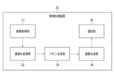
図3は、映像処理装置20の機能構成の一例を示す図である。図3に示すように、映像処理装置20は、例えば画像取得部31、最適化処理部32、パタン生成部33、画像生成部34、及び通信部35を備える。画像取得部31、最適化処理部32、パタン生成部33、画像生成部34、及び通信部35の処理は、例えば、プロセッサ201及び通信モジュール204によって実現される。
Figure 3 is a diagram showing an example of the functional configuration of the
画像取得部31は、映像処理装置20で使用する視点画像を取得する。画像取得部31は、例えばカメラである。最適化処理部32は、画像取得部31が取得した視点画像に基づいて、所定の処理を実行する。パタン生成部33は、画像取得部31が取得した視点画像及び最適化処理部32の処理結果に基づいて、視差誘導パタンを生成する。視差誘導パタンは、基準となる所定の画像とともに所定の処理が実行されることにより、例えば図1で説明した視差W1及び視差W2を実現する。画像生成部34は、パタン生成部33が生成した視差誘導パタンと基準となる所定の画像とに基づいて、ステレオペア画像を生成する。通信部35は、画像生成部34で生成されたステレオペア画像を所定の方法で送信する。例えば、通信部35は、映像処理装置20に接続された画像出力デバイスにステレオペア画像を送信することにより、画像出力デバイスからステレオペア画像を出力させる。The
次に、映像処理装置20がステレオペア画像を生成する方法について詳細に説明する。図4は、映像処理装置20がステレオペア画像を生成する処理の一例を説明する説明図である。画像取得部31は、前述したように、左目視点画像PLP、中間視点画像PCP、及び右目視点画像PRPを取得する。最適化処理部32は、これら3つの画像に基づいて、視差誘導パタンIDを生成する。本実施形態では、中間視点画像PCPが基準となる所定の画像(基準画像)として使用される。最適化処理部32は、左目視点画像PLP、中間視点画像PCP、及び右目視点画像PRPのそれぞれを周波数-位相成分へと変換する。周波数-位相成分への変換は、非特許文献1に記載の方法と同様の処理により実行される。中間視点画像PCPの周波数-位相成分への変換後における、周波数i及び位置jの位相成分をX(i,j)と表記する。左目視点画像PLPの周波数-位相成分への変換後における、周波数i及び位置jの位相成分をL(i,j)と表記する。右目視点画像PRPの周波数-位相成分への変換後における、周波数i及び位置jの位相成分をR(i,j)と表記する。Next, a method in which the
最適化処理部32は、中間視点画像PCPをy度位相シフトさせる。最適化処理部32は、中間視点画像PCPの位相成分X(i,j)に位相シフト量y(i,j)を加えることで、位相シフトさせた中間視点画像PCPshiftを生成する。最適化処理部32は、中間視点画像PCPと位相シフトさせた中間視点画像PCPshiftとを加算することで、左目視点画像PLPを推定した、推定左目視点画像PLPasmを生成する。このとき、最適化処理部32は、位相シフトさせた中間視点画像PCPshiftに重みAを掛け合わせた状態で、中間視点画像PCPとの加算を実行する。重みAの値は、例えば、所定の初期値が予め設定される。最適化処理部32は、推定左目視点画像PLPasmに基づいて、推定左目視点画像PLPasmにおける中間視点画像PCPからの推定位相シフト量zL(i,j)を算出する。
The
同様にして、最適化処理部32は、中間視点画像PCPから位相シフトさせた中間視点画像PCPshiftを減算することで、右目視点画像PRPを推定した推定右目視点画像PRPasmを生成する。このとき、最適化処理部32は、位相シフトさせた中間視点画像PCPshiftに重みAを掛け合わせた状態で、中間視点画像PCPとの減算を実行する。最適化処理部32は、推定右目視点画像PRPasmに基づいて、推定右目視点画像PRPasmにおける中間視点画像PCPからの推定位相シフト量zR(i,j)を算出する。
Similarly, the
最適化処理部32は、式(1)で表される誤差Nを最小化する条件の下で、重みA及び位相シフト量yの組(A,y)を最適化する。推定位相シフト量zL(i,j),zR(i,j)が重みA及び位相シフト量yの両方に依存して変化するため、誤差Nを最小化することにより、組(A,y)が最適化される。重みA及び位相シフト量yの組は、例えば、全探索により決定する。この誤差Nの最小化計算により、最適化処理部32は、最適重みAopt及び最適位相シフト量yoptの組(Aopt,yopt)を算出する。
The
![]()
![]()
最適化処理部32が算出した最適重みAopt及び最適位相シフト量yoptに基づいて、パタン生成部33は視差誘導パタンIDを生成する。視差誘導パタンIDの生成は、非特許文献1に記載の方法と同様の処理により実行される。画像生成部34は、パタン生成部33により生成された視差誘導パタンIDと中間視点画像PCPとを加算することにより、左目位置PLにおける、ステレオぺア画像のうちの一方を生成する。画像生成部34は、中間視点画像PCPからパタン生成部により生成された視差誘導パタンIDを減算することにより、右目位置PRにおける、ステレオぺア画像のうちの他方を生成する。このようにして、画像生成部34は、ステレオペア画像を生成する。
Based on the optimal weight A opt and the optimal phase shift amount y opt calculated by the
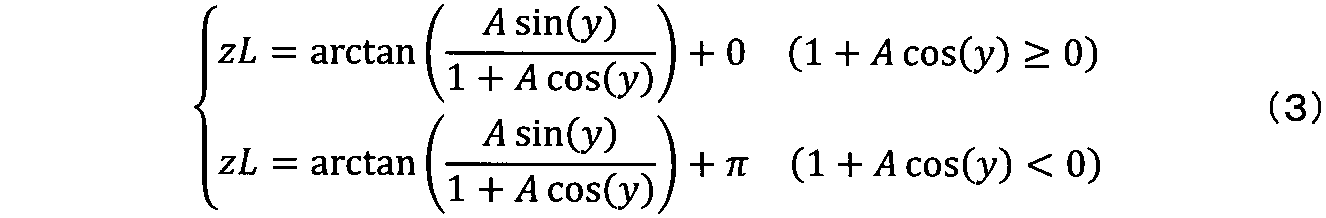
前述した最適化処理を、視点位置の位相θにおけるレベルが正弦波の強度で表される場合で、具体的に説明する。この場合、中間位置PCの位相Xにおける強度はsin(X)と表される。このとき、位相Xをy度位相シフトさせると、位相シフト後の強度はsin(X+y)と表される。最適化処理部32は、位相Xにおける強度sin(X)と、位相シフト後の強度sin(X+y)を重みAにより重み付けしたAsin(X+y)とを加算した結果を、左目位置PLの位相Lにおける推定強度とする。このときの推定強度を、位相X、推定位相シフト量zL、及び重みBLを用いて表すと式(2)のように表される。The above-mentioned optimization process will be specifically described in the case where the level at the phase θ of the viewpoint position is expressed as the intensity of a sine wave. In this case, the intensity at the phase X of the intermediate position PC is expressed as sin(X). At this time, when the phase X is shifted by y degrees, the intensity after the phase shift is expressed as sin(X+y). The
![]()
![]()
よって、推定位相シフト量zLは式(3)のように表される。Therefore, the estimated phase shift amount zL is expressed as equation (3).
同様にして、最適化処理部32は、位相Xにおける強度sin(X)から、位相シフト後の強度sin(X+y)を重みAにより重み付けしたAsin(X+y)を減算した結果を、右目位置PRの位相Rにおける推定強度とする。このときの推定強度を、位相X、推定位相シフト量zR、及び重みBRを用いて表すと式(4)のように表される。
Similarly, the
![]()
![]()
よって、推定位相シフト量zRは式(5)のように表される。Therefore, the estimated phase shift amount zR is expressed as equation (5).

これらを用いて、最適化処理部32は、式(1)で表される誤差Nを最小化する条件の下で、重みA及び位相シフト量yの組(A,y)を最適化する。Using these, the
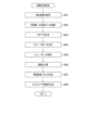
図5は、実施形態に係る映像処理装置20で実行される処理の一例を説明するフローチャートである。図5の処理は、映像処理装置20がステレオペア画像を生成するタイミングで繰り返し実行される。したがって、図5の処理は、ステレオペア画像を生成する画像生成処理の1回の処理におけるフローチャートの一例である。
Figure 5 is a flowchart illustrating an example of processing executed by the
ステレオペア画像を生成するタイミングでは、映像処理装置20は、画像取得部31により視点画像を取得する(S501)。このとき、画像取得部31は、左目視点画像PLP、中間視点画像PCP、及び右目視点画像PRPをそれぞれ取得する。映像処理装置20は、前述したようにして、取得した左目視点画像PLP、中間視点画像PCP、及び右目視点画像PRPを周波数-位相成分へ変換する(S502)。映像処理装置20は、前述したようにして位相シフトさせた中間視点画像PCPshiftを生成する(S503)。映像処理装置20は、前述したようにして、中間視点画像PCPと位相シフトさせた中間視点画像PCPshiftとに基づいて、推定左目視点画像PLPasm及び推定右目視点画像PRPasmを生成する(S504)。映像処理装置20は、推定左目視点画像PLPasmに基づいて推定位相シフト量zL(i,j)を推定し、推定右目視点画像PRPasmに基づいて推定位相シフト量zR(i,j)を推定する(S505)。映像処理装置20は、前述したようにして、誤差Nを最小化する条件下、位相シフト成分y(i,j)及び重みA(i,j)の組を最適化する(S506)。映像処理装置20は、前述したようにして、最適重みAopt及び最適位相シフト量yoptに基づいて、視差誘導パタンIDを生成する(S507)。映像処理装置20は、前述したようにして、中間視点画像PCP及び視差誘導パタンIDに基づいて、ステレオペア画像を生成する(S508)。以上により、映像処理装置20はステレオペア画像の生成処理を完了する。
At the timing of generating the stereo pair images, the
本実施形態では、映像処理装置20は、画像取得部31、最適化処理部32、パタン生成部33、及び画像生成部34を具備する。画像取得部31は、左目位置PLから表示領域RSを撮影した左目視点画像PLPと、右目位置PRから表示領域RSを撮影した右目視点画像PRPと、左目位置PL及び右目位置PRの中間から表示領域RSを撮影した中間視点画像PCPと、を取得する。最適化処理部32は、中間視点画像PCPに基づいて算出された位相シフト量y及び重みAを、左目視点画像PLP及び右目視点画像PRPに基づいて最適化する。パタン生成部33は、最適化された最適位相シフト量yopt及び最適化された最適重みAoptに基づいて、左目位置PL及び右目位置PRの間の視差に対応する視差誘導パタンIDを生成する。画像生成部34は、中間視点画像PCP及び視差誘導パタンIDに基づいて、ステレオペア画像を生成する。このように、映像処理装置20は位相シフト量及び重みAを左目視点画像PLP及び右目視点画像PRPに基づいて最適化するため、視差が左右非対称である場合においても適切な視差をユーザに与えることができる。したがって、映像処理装置20はユーザに適切な奥行き表現を提供することができる。
In this embodiment, the
(変形例)
図6は、変形例に係る映像処理装置20がステレオペア画像を生成するときの表示領域RSの分割方法の一例を説明する説明図である。本変形例では、中間位置PCを基準として、現実の表示領域RSを所定の個数に分割し、分割された領域ごとに位相シフト量y及び重みAを最適化する。すなわち、分割された領域内において、位相シフト量yは同一であり、重みAは同一である。現実の表示領域RSの分割数は、特に限定されるものではない。図6の一例では、現実の表示領域RSを3分割し、それぞれ左側領域AL、中央領域AC、及び右側領域ARとする。この場合、映像処理装置20は、左側領域ALにおいて位相シフト量y及び重みAを最適化し、中央領域ACにおいて位相シフト量y及び重みAを最適化し、右側領域ARにおいて位相シフト量y及び重みAを最適化する。
(Modification)
FIG. 6 is an explanatory diagram for explaining an example of a method of dividing the display area RS when the
図7は、変形例に係る映像処理装置20がステレオペア画像を生成する処理の一例を説明する説明図である。本変形例では、最適化処理部32が中間視点画像PCPをy度位相シフトさせるとき、表示領域RSが分割された分割領域内のそれぞれにおいて、共通の位相シフト量ypartが用いられる。最適化処理部32は、分割領域内のそれぞれにおける中間視点画像PCPの位相成分X(i,j)に位相シフト量ypartを加えることで、位相シフトさせた中間視点画像(PCPshift)partを、分割領域ごとに生成する。
7 is an explanatory diagram for explaining an example of a process in which the
最適化処理部32は、中間視点画像PCPと位相シフトさせた中間視点画像(PCPshift)partとを分割領域ごとに加算することで、左目視点画像PLPの対応する部分を推定した推定左目視点画像(PLPasm)partを生成する。このとき、最適化処理部32は、位相シフトさせた中間視点画像(PCPshift)partに重みApartを掛け合わせた状態で、中間視点画像PCPとの加算を実行する。最適化処理部32は、分割領域ごとの推定左目視点画像(PLPasm)partに基づいて、中間視点画像PCPからの推定位相シフト量zLpartを推定する。
The
最適化処理部32は、分割領域ごとに、式(1)で表される誤差Nを最小化する条件の下で、重みApart及び位相シフト量ypartの組(Apart,ypart)を最適化する。最適化処理部32が、分割領域ごとに算出した最適重み(Apart)opt及び最適位相シフト量(ypart)optに基づいて、パタン生成部33は分割領域ごとに視差誘導パタンIDpartを生成する。画像生成部34は、パタン生成部33により生成された視差誘導パタンIDpart及び分割領域に対応する中間視点画像PCPの部分を加算することにより、分割領域に対応する、左目位置PLにおけるステレオぺア画像の一方を生成する。画像生成部34は、分割領域に対応する中間視点画像PCPからパタン生成部33により生成された視差誘導パタンIDpartを減算することにより、分割領域に対応する、右目位置PRにおけるステレオぺア画像の他方を生成する。全分割領域において、分割領域に対応するステレオペア画像の生成が完了した後、画像生成部34は、各分割領域に対応するステレオペア画像を合成することにより、表示領域RSに対応するステレオペア画像を生成する。
The
図8は、本変形例の映像処理装置20で実行される処理の一例を説明するフローチャートである。ステレオペア画像を生成するタイミングでは、映像処理装置20は、画像取得部31により視点画像を取得する(S801)。このとき、画像取得部31は、左目視点画像PLP、中間視点画像PCP、及び右目視点画像PRPをそれぞれ取得する。映像処理装置20は、前述したようにして、取得した左目視点画像PLP、中間視点画像PCP、及び右目視点画像PRPを周波数-位相成分へ変換する(S802)。映像処理装置20は、前述したようにして位相シフトさせた中間視点画像(PCPshift)partを分割領域ごとに生成する(S803)。映像処理装置20は、前述したようにして、中間視点画像PCPと位相シフトさせた中間視点画像(PCPshift)partとに基づいて、推定左目視点画像(PLPasm)part及び推定右目視点画像(PRPasm)partを分割領域ごとに生成する(S804)。
8 is a flowchart for explaining an example of processing executed by the
映像処理装置20は、推定左目視点画像(PLPasm)partに基づいて推定位相シフト量zLpartを分割領域ごとに推定し、推定右目視点画像(PRPasm)partに基づいて推定位相シフト量zRpartを分割領域ごとに推定する(S805)。映像処理装置20は、前述したようにして、誤差Nを最小化する条件下、位相シフト量ypart及び重みApartの組を分割領域ごとに最適化する(S806)。映像処理装置20は、前述したようにして、最適重み(Apart)opt及び最適位相シフト量(ypart)optに基づいて、視差誘導パタンIDpartを分割領域ごとに生成する(S807)。映像処理装置20は、前述したようにして、中間視点画像PCP及び視差誘導パタンIDpartに基づいて、ステレオペア画像を分割領域ごとに生成する(S808)。映像処理装置20は、分割領域ごとのステレオペア画像を合成することにより、表示領域RSに対応するステレオペア画像を生成する(S809)。以上により、映像処理装置20はステレオペア画像の生成を完了する。
The
本変形例においても、前述の実施形態と同様に、映像処理装置20は位相シフト量y及び重みAを左目視点画像PLP及び右目視点画像PRPに基づいて最適化するため、視差が左右非対称である場合においても適切な視差をユーザに与えることができる。したがって、映像処理装置20はユーザに適切な奥行き表現を与えることができる。In this modified example, as in the above embodiment, the
別の変形例では、映像処理装置20は、左目位置PL、右目位置PR、及び中間位置PCをリアルタイムで取得してもよい。左目位置PL、右目位置PR、及び中間位置PCのリアルタイムでの取得は、例えば、ユーザのヘッドトラッキングにより実行される。この場合、映像処理装置20は、リアルタイムで取得した左目位置PL、右目位置PR、及び中間位置PCに基づいて、ステレオペア画像をリアルタイムで生成する。そのため、映像処理装置20は、図5又は図8に示す処理を、左目位置PL、右目位置PR、及び中間位置PCが更新されるたびに実行する。このように、リアルタイムで左目位置PL、右目位置PR、及び中間位置PCを取得することで、ユーザのリアルタイムでの視点を反映したステレオペア画像が生成される。よって、映像処理装置20は、ユーザにさらに適正な奥行き表現を提供することができる。In another modified example, the
前述の実施形態等に記載された手法は、コンピュータに実行させることができるプログラム(ソフトウェア)として、例えば、磁気ディスク、光ディスク、半導体メモリ等の記憶媒体に格納して頒布され得る。記憶媒体は、頒布用に限らず、計算機内部あるいはネットワークを介して接続される機器に設けられた磁気ディスク、半導体メモリ等の記憶媒体を含む。また、実施形態に記載された手法は、通信媒体により伝送して頒布され得る。媒体側に格納されるプログラムには、コンピュータに実行させるソフトウェアをコンピュータ内に構成させる設定プログラムをも含む。ソフトウェアには、実行プログラムのみならずテーブル、データ構造も含む。本システムを実現するコンピュータは、記憶媒体に記録されたプログラムを読み込むとともに、ソフトウェアにより動作が制御されることで、前述の処理を実行する。ソフトウェアは、コンピュータが設定プログラムにより構築してもよい。The methods described in the above-mentioned embodiments and the like can be distributed as a program (software) that can be executed by a computer, stored in a storage medium such as a magnetic disk, optical disk, or semiconductor memory. The storage medium is not limited to a storage medium for distribution, but includes a storage medium such as a magnetic disk or semiconductor memory provided inside a computer or in a device connected via a network. The methods described in the embodiments can also be distributed by transmission via a communication medium. The program stored on the medium side also includes a setting program that configures the software to be executed by a computer within the computer. Software includes not only execution programs but also tables and data structures. The computer that realizes this system reads the program recorded on the storage medium and executes the above-mentioned processing by being controlled by the software. The software may be constructed by the computer using a setting program.
なお、本発明は、上記実施形態に限定されるものではなく、実施段階ではその要旨を逸脱しない範囲で種々に変形することが可能である。また、各実施形態は適宜組み合わせて実施してもよく、その場合組み合わせた効果が得られる。更に、上記実施形態には種々の発明が含まれており、開示される複数の構成要件から選択された組み合わせにより種々の発明が抽出され得る。例えば、実施形態に示される全構成要件からいくつかの構成要件が削除されても、課題が解決でき、効果が得られる場合には、この構成要件が削除された構成が発明として抽出され得る。 Note that the present invention is not limited to the above-described embodiments, and can be modified in various ways in the implementation stage without departing from the gist of the invention. The embodiments may also be implemented in appropriate combination, in which case the combined effects can be obtained. Furthermore, the above-described embodiments include various inventions, and various inventions can be extracted by combinations selected from the multiple constituent elements disclosed. For example, if the problem can be solved and an effect can be obtained even if some constituent elements are deleted from all the constituent elements shown in the embodiments, the configuration from which these constituent elements are deleted can be extracted as an invention.
20…映像処理装置
201…プロセッサ
202…記憶媒体
203…ユーザインタフェース
204…通信モジュール
31…画像取得部
32…最適化処理部
33…パタン生成部
34…画像生成部
35…通信部
ID…視差誘導パタン
RS…表示領域
PL…左目位置
PR…右目位置
PC…中間位置
PLP…左目視点画像
PRP…右目視点画像
PCP…中間視点画像
20: Video processing device 201: Processor 202: Storage medium 203: User interface 204: Communication module 31: Image acquisition unit 32: Optimization processing unit 33: Pattern generation unit 34: Image generation unit 35: Communication unit ID: Parallax induction pattern RS: Display area PL: Left eye position PR: Right eye position PC: Intermediate position PLP: Left eye viewpoint image PRP: Right eye viewpoint image PCP: Intermediate viewpoint image
Claims (7)
前記中間視点画像に基づいて算出された位相シフト量及び重みを、前記左目視点画像及び前記右目視点画像に基づいて最適化する最適化処理部と、
最適化された前記位相シフト量及び最適化された前記重みに基づいて、前記左目位置及び前記右目位置の間の視差に対応する視差誘導パタンを生成するパタン生成部と、
前記中間視点画像及び前記視差誘導パタンに基づいて、ステレオペア画像を生成する画像生成部と、
を具備する、映像処理装置。 an image acquisition unit that acquires a left-eye viewpoint image obtained by capturing a display area from a left eye position, a right-eye viewpoint image obtained by capturing the display area from a right eye position, and an intermediate viewpoint image obtained by capturing the display area from an intermediate position between the left eye position and the right eye position;
an optimization processing unit that optimizes the amount of phase shift and the weight calculated based on the intermediate viewpoint image based on the left-eye viewpoint image and the right-eye viewpoint image;
a pattern generator that generates a disparity-inducing pattern corresponding to a disparity between the left eye position and the right eye position based on the optimized phase shift amount and the optimized weight;
an image generating unit that generates a stereo pair image based on the intermediate viewpoint image and the parallax inducing pattern;
A video processing device comprising:
前記中間視点画像の位相を前記位相シフト量に基づいてシフトさせ、
前記重み、前記中間視点画像、及び位相シフトされた前記中間視点画像に基づいて、前記左目視点画像を推定した推定左目視点画像、及び、前記右目視点画像を推定した推定右目視点画像を生成し、
前記推定左目視点画像における前記中間視点画像からの推定位相シフト量、及び、前記推定右目視点画像における前記中間視点画像からの推定位相シフト量を算出し、
前記推定左目視点画像の推定位相シフト量、及び、前記右目視点画像の推定位相シフト量に基づいて、前記重み及び前記位相シフト量を最適化する、
請求項1に記載の映像処理装置。 The optimization processing unit:
shifting a phase of the intermediate viewpoint image based on the phase shift amount;
generating an estimated left-eye viewpoint image by estimating the left-eye viewpoint image and an estimated right-eye viewpoint image by estimating the right-eye viewpoint image based on the weights, the intermediate viewpoint image, and the phase-shifted intermediate viewpoint image;
calculating an estimated phase shift amount in the estimated left-eye viewpoint image from the intermediate viewpoint image, and an estimated phase shift amount in the estimated right-eye viewpoint image from the intermediate viewpoint image;
optimizing the weight and the phase shift amount based on an estimated phase shift amount of the estimated left-eye viewpoint image and an estimated phase shift amount of the right-eye viewpoint image;
The video processing device according to claim 1 .
前記中間視点画像と前記視差誘導パタンとを加算することにより、前記ステレオペア画像のうち前記左目位置に対応する画像を生成し、
前記中間視点画像から前記視差誘導パタンを減算することにより、前記ステレオペア画像のうち前記右目位置に対応する画像を生成する、
請求項1に記載の映像処理装置。 The image generating unit includes:
generating an image corresponding to the left eye position among the stereo pair images by adding the intermediate viewpoint image and the parallax inducing pattern;
generating an image corresponding to the right eye position from the stereo pair images by subtracting the parallax inducing pattern from the intermediate viewpoint image;
The video processing device according to claim 1 .
前記最適化処理部は、複数の前記表示領域のそれぞれにおいて前記位相シフト量及び前記重みを最適化し、
前記パタン生成部は、複数の前記表示領域のそれぞれにおいて前記視差誘導パタンを生成し、
前記画像生成部は、複数の前記表示領域のそれぞれにおいて前記ステレオペア画像を生成するとともに、複数の前記表示領域のそれぞれに対応する前記ステレオペア画像から前記表示領域の全体に対応する前記ステレオペア画像を生成する、
請求項1に記載の映像処理装置。 The display area includes a plurality of the display areas,
the optimization processing unit optimizes the phase shift amount and the weight in each of the plurality of display regions;
The pattern generation unit generates the parallax inducing pattern in each of the plurality of display regions,
the image generation unit generates the stereo pair images in each of the plurality of display areas, and generates the stereo pair image corresponding to the entirety of the display area from the stereo pair images corresponding to each of the plurality of display areas,
The video processing device according to claim 1 .
請求項1に記載の映像処理装置。 The image acquisition unit acquires the left eye position, the right eye position, and the intermediate position in real time.
The video processing device according to claim 1 .
前記中間視点画像に基づいて算出された位相シフト量及び重みを、前記左目視点画像及び前記右目視点画像に基づいて最適化することと、
最適化された前記位相シフト量及び最適化された前記重みに基づいて、前記左目位置及び前記右目位置の間の視差に対応する視差誘導パタンを生成することと、
前記中間視点画像及び前記視差誘導パタンに基づいて、ステレオペア画像を生成することと、
を具備する、映像処理方法。 Obtaining a left-eye viewpoint image obtained by photographing a display area from a left eye position, a right-eye viewpoint image obtained by photographing the display area from a right eye position, and an intermediate viewpoint image obtained by photographing the display area from an intermediate position between the left eye position and the right eye position;
optimizing the phase shift amount and the weight calculated based on the intermediate viewpoint image based on the left eye viewpoint image and the right eye viewpoint image;
generating a disparity-inducing pattern corresponding to a disparity between the left eye position and the right eye position based on the optimized phase shift amount and the optimized weights;
generating a stereo pair image based on the intermediate viewpoint image and the parallax inducing pattern;
A video processing method comprising:
左目位置から表示領域を撮影した左目視点画像と、右目位置から前記表示領域を撮影した右目視点画像と、前記左目位置及び前記右目位置の中間位置から前記表示領域を撮影した中間視点画像と、を取得させ、
前記中間視点画像に基づいて算出された位相シフト量及び重みを、前記左目視点画像及び前記右目視点画像に基づいて最適化させ、
最適化された前記位相シフト量及び最適化された前記重みに基づいて、前記左目位置及び前記右目位置の間の視差に対応する視差誘導パタンを生成させ、
前記中間視点画像及び前記視差誘導パタンに基づいて、ステレオペア画像を生成させる、
映像処理プログラム。
On the computer,
acquiring a left-eye viewpoint image obtained by photographing a display area from a left eye position, a right-eye viewpoint image obtained by photographing the display area from a right eye position, and an intermediate viewpoint image obtained by photographing the display area from an intermediate position between the left eye position and the right eye position;
optimizing the phase shift amount and the weight calculated based on the intermediate viewpoint image based on the left eye viewpoint image and the right eye viewpoint image;
generating a disparity-inducing pattern corresponding to a disparity between the left eye position and the right eye position based on the optimized phase shift amount and the optimized weights;
generating a stereo pair image based on the intermediate viewpoint image and the parallax inducing pattern;
Image processing program.
Applications Claiming Priority (1)
| Application Number | Priority Date | Filing Date | Title |
|---|---|---|---|
| PCT/JP2021/033764 WO2023042266A1 (en) | 2021-09-14 | 2021-09-14 | Video processing device, video processing method, and video processing program |
Publications (2)
| Publication Number | Publication Date |
|---|---|
| JPWO2023042266A1 JPWO2023042266A1 (en) | 2023-03-23 |
| JP7597232B2 true JP7597232B2 (en) | 2024-12-10 |
Family
ID=85602001
Family Applications (1)
| Application Number | Title | Priority Date | Filing Date |
|---|---|---|---|
| JP2023547973A Active JP7597232B2 (en) | 2021-09-14 | 2021-09-14 | Image processing device, image processing method, and image processing program |
Country Status (2)
| Country | Link |
|---|---|
| JP (1) | JP7597232B2 (en) |
| WO (1) | WO2023042266A1 (en) |
Citations (2)
| Publication number | Priority date | Publication date | Assignee | Title |
|---|---|---|---|---|
| JP2004522382A (en) | 2001-07-23 | 2004-07-22 | コーニンクレッカ フィリップス エレクトロニクス エヌ ヴィ | Stereoscopic image processing apparatus and method |
| JP2019185589A (en) | 2018-04-16 | 2019-10-24 | 日本電信電話株式会社 | Image generation device, image generation method, and program |
Family Cites Families (2)
| Publication number | Priority date | Publication date | Assignee | Title |
|---|---|---|---|---|
| JP5347717B2 (en) * | 2008-08-06 | 2013-11-20 | ソニー株式会社 | Image processing apparatus, image processing method, and program |
| JP6615824B2 (en) * | 2016-09-23 | 2019-12-04 | 日本電信電話株式会社 | Image generating apparatus, image generating method, and program |
-
2021
- 2021-09-14 JP JP2023547973A patent/JP7597232B2/en active Active
- 2021-09-14 WO PCT/JP2021/033764 patent/WO2023042266A1/en not_active Ceased
Patent Citations (2)
| Publication number | Priority date | Publication date | Assignee | Title |
|---|---|---|---|---|
| JP2004522382A (en) | 2001-07-23 | 2004-07-22 | コーニンクレッカ フィリップス エレクトロニクス エヌ ヴィ | Stereoscopic image processing apparatus and method |
| JP2019185589A (en) | 2018-04-16 | 2019-10-24 | 日本電信電話株式会社 | Image generation device, image generation method, and program |
Non-Patent Citations (2)
| Title |
|---|
| 吹上大樹 他1名,技術解説 人間の視覚の理解に基づいたステレオ画像生成手法「Hidden Stereo」,映像情報メディア学会誌,2020年05月01日,Vol.74, No.3,pp.485-490 |
| 巻口誉宗 他3名,360度裸眼3D映像表示技術への視差誘導パターンを用いた画質変動軽減手法の適用性評価,2018年映像情報メディア学会冬季大会講演予稿集,2018年12月21日 |
Also Published As
| Publication number | Publication date |
|---|---|
| WO2023042266A1 (en) | 2023-03-23 |
| JPWO2023042266A1 (en) | 2023-03-23 |
Similar Documents
| Publication | Publication Date | Title |
|---|---|---|
| CN112136324B (en) | A Multi-Focal Plane-Based Method for Generating Stereo Viewpoints in DIBR Systems (MFP-DIBR) | |
| KR101529812B1 (en) | Run-time conversion of native monoscopic 3d into stereoscopic 3d | |
| KR101851180B1 (en) | Morphological anti-aliasing (mlaa) of a re-projection of a two-dimensional image | |
| CN103518372B (en) | Image processing device, image processing method, and program | |
| US20090282429A1 (en) | Viewer tracking for displaying three dimensional views | |
| JP5942195B2 (en) | 3D image processing apparatus, 3D imaging apparatus, and 3D image processing method | |
| WO2012056686A1 (en) | 3d image interpolation device, 3d imaging device, and 3d image interpolation method | |
| JP2014010805A (en) | Image processing device, image processing method and image processing program | |
| JP4489610B2 (en) | Stereoscopic display device and method | |
| CN107087149B (en) | Method and apparatus for processing holographic image | |
| US20120176367A1 (en) | Morphological anti-aliasing (mlaa) of a re-projection of a two-dimensional image | |
| JP7597232B2 (en) | Image processing device, image processing method, and image processing program | |
| EP4030752A1 (en) | Image generation system and method | |
| CN112470470B (en) | Multi-focus display device and method | |
| JPWO2012176526A1 (en) | Stereoscopic image processing apparatus, stereoscopic image processing method, and program | |
| KR101826025B1 (en) | System and method for generating 3d image contents that user interaction is possible | |
| JP7218801B2 (en) | Image generation device, image generation method, program | |
| JP7827070B2 (en) | Image processing device and image processing method | |
| Lee | 1-Way Directional Subpixel Rendering Method for Glasses-free 3D Display. | |
| JP2011066507A (en) | Image processing apparatus | |
| KR102732451B1 (en) | Apparatus and method for processing hologram image data | |
| RU2523980C2 (en) | Method and system for displaying set of multimedia objects on 3d display | |
| JP2019159886A (en) | Image generation method and image generation device | |
| JP2015231178A (en) | Image selection device, stereoscopic image display system, image selection method, and image selection program | |
| Vismara et al. | Analysis of stereoscopic visualization in a consumer-oriented head mounted display |
Legal Events
| Date | Code | Title | Description |
|---|---|---|---|
| A621 | Written request for application examination |
Free format text: JAPANESE INTERMEDIATE CODE: A621 Effective date: 20240215 |
|
| TRDD | Decision of grant or rejection written | ||
| A01 | Written decision to grant a patent or to grant a registration (utility model) |
Free format text: JAPANESE INTERMEDIATE CODE: A01 Effective date: 20241029 |
|
| A61 | First payment of annual fees (during grant procedure) |
Free format text: JAPANESE INTERMEDIATE CODE: A61 Effective date: 20241111 |
|
| R150 | Certificate of patent or registration of utility model |
Ref document number: 7597232 Country of ref document: JP Free format text: JAPANESE INTERMEDIATE CODE: R150 |
|
| S533 | Written request for registration of change of name |
Free format text: JAPANESE INTERMEDIATE CODE: R313533 |
|
| R350 | Written notification of registration of transfer |
Free format text: JAPANESE INTERMEDIATE CODE: R350 |