JP7596830B2 - Display device, display method, and program - Google Patents
Display device, display method, and program Download PDFInfo
- Publication number
- JP7596830B2 JP7596830B2 JP2021016604A JP2021016604A JP7596830B2 JP 7596830 B2 JP7596830 B2 JP 7596830B2 JP 2021016604 A JP2021016604 A JP 2021016604A JP 2021016604 A JP2021016604 A JP 2021016604A JP 7596830 B2 JP7596830 B2 JP 7596830B2
- Authority
- JP
- Japan
- Prior art keywords
- correction
- mode
- voice
- touch operation
- display
- Prior art date
- Legal status (The legal status is an assumption and is not a legal conclusion. Google has not performed a legal analysis and makes no representation as to the accuracy of the status listed.)
- Active
Links
Images


Landscapes
- User Interface Of Digital Computer (AREA)
Description
本発明は、表示装置、表示方法およびプログラムに関する。 The present invention relates to a display device, a display method, and a program.
音声の入力を受け付けて、入力された音声を音声認識によって文字に変換して表示する表示装置が開示されている。 A display device is disclosed that accepts voice input, converts the input voice into text using voice recognition, and displays the text.
例えば、特許文献1には、音声受付手段が受け付けた音声のテキストデータに係る文字の表示部への表示属性を決定し、決定された表示属性に基づき文字を表示する入力表示装置が開示されている。表示属性とは、例えば、表示すべき文字又は文字列の表示開始及び表示終了位置、フォントサイズ、縦書きまたは横書き等である。 For example, Patent Document 1 discloses an input display device that determines the display attributes of characters related to the text data of the voice received by a voice receiving means on a display unit, and displays the characters based on the determined display attributes. The display attributes include, for example, the display start and end positions of the character or character string to be displayed, the font size, vertical or horizontal writing, etc.
従来の技術では、音声認識による文字表示において、音声認識を開始するタイミングの指定、文字を表示する位置の指定および表示された文字の訂正等の操作が煩雑であり、操作性が低いという問題がある。 In conventional technology, when displaying characters using voice recognition, the operations required to specify the timing to start voice recognition, specify the position to display the characters, and correct the displayed characters are cumbersome, resulting in low operability.
開示の技術は、音声認識による文字表示における操作性を向上させることを目的とする。 The disclosed technology aims to improve the ease of use when displaying text using voice recognition.
開示の技術は、画面への第一のタッチ操作が検出されると、音声の入力を受け付けて、入力された音声を音声認識によって文字に変換する音声処理部と、前記画面における前記第一のタッチ操作を受けた位置に、変換された前記文字を表示する制御を行う表示制御部と、を備え、前記音声処理部は、前記音声認識によって表示された文字への第二のタッチ操作が検出されると、前記第二のタッチ操作を前記文字の訂正操作として受け付け、画面への第一のタッチ操作が検出されると、訂正機能についての動作モードを訂正ONモードに切り替え、前記訂正機能についての動作モードが前記訂正ONモードである場合に、前記音声認識によって表示された文字への前記第二のタッチ操作が検出されると、前記第二のタッチ操作を前記文字の訂正操作として受け付け、訂正ONモードの開始から一定時間が経過すると、訂正機能についての動作モードを訂正OFFモードに切り替える表示装置である。
The disclosed technology is a display device that includes a voice processing unit that, when a first touch operation on a screen is detected, accepts voice input and converts the input voice into characters through voice recognition, and a display control unit that controls displaying the converted characters at the position on the screen where the first touch operation was received, and when a second touch operation on a character displayed by the voice recognition is detected, the voice processing unit accepts the second touch operation as a correction operation for the character , and when a first touch operation on the screen is detected, switches an operation mode for a correction function to a correction ON mode, and when the operation mode for the correction function is the correction ON mode, when a second touch operation on a character displayed by the voice recognition is detected, accepts the second touch operation as a correction operation for the character, and when a certain time has elapsed since the start of the correction ON mode, switches the operation mode for the correction function to a correction OFF mode .
音声認識による文字表示における操作性を向上させることができる。 This can improve the ease of use when displaying text using voice recognition.
以下に図面を参照して、本発明の実施の形態について説明する。 The following describes an embodiment of the present invention with reference to the drawings.
まず、本実施形態に係る用語について説明する。手書きデータとは、ディスプレー上でユーザが入力手段を連続的に移動させた座標点列を軌跡として表示したデータである。また、ユーザがディスプレーに入力手段を押しつけてから連続的に移動させた後、ディスプレーから離すという一連の操作をストロークといい、ストロークにより手書きされたデータをストロークデータという。ストロークデータは、座標点列を示す座標群とも言える。 First, the terminology used in this embodiment will be explained. Handwritten data is data that displays as a trajectory a sequence of coordinate points created by a user continuously moving the input tool on a display. A series of operations in which the user presses the input tool against the display, continuously moves it, and then removes it from the display is called a stroke, and data handwritten using strokes is called stroke data. Stroke data can also be thought of as a coordinate group that indicates a sequence of coordinate points.
手書きデータは1つ以上のストロークデータを有する。具体的には、手書きデータは、ストロークが終了してから次のストロークを開始するまでの時間、すなわち、入力手段をディスプレーから離してから接触させるまでの時間が、所定の時間よりも短い複数のストロークデータをまとめたデータである。したがって、手書きデータは、手書きデータが有するストロークデータが示す座標群を含む。 The handwritten data has one or more stroke data. Specifically, the handwritten data is a compilation of multiple stroke data in which the time between the end of a stroke and the start of the next stroke, i.e., the time between removing the input means from the display and touching it back, is shorter than a predetermined time. Therefore, the handwritten data includes a group of coordinates indicated by the stroke data contained in the handwritten data.
入力手段は、ディスプレーの座標を指定して手書きデータを入力するための手段である。例えば、ペン、人の指や手、棒状部材などは、入力手段の一例である。 The input means is a means for inputting handwritten data by specifying coordinates on the display. Examples of input means include a pen, a human finger or hand, and a rod-shaped member.
次に、表示装置の構成について説明する。 Next, we will explain the configuration of the display device.
図1は、表示装置の全体構成の一例を示す図である。 Figure 1 shows an example of the overall configuration of a display device.
(a)では、表示装置2の一例として、壁につり下げられた横長の電子黒板として使用される表示装置2を示している。
(a) shows an example of a
(b)は壁につり下げられた縦長の電子黒板として使用される表示装置2を示している。
(b) shows the
(c)は机230に平置きされた表示装置2を示す。表示装置2は厚みが1cm程度なので、一般の机に平置きしても机の高さを調整する必要がない。また、容易に移動できる。
(c) shows the
表示装置2には表示部の一例としてのディスプレー220が設置されている。ユーザUは、ペン2500を用いて、ディスプレー220に文字等を手書きする(入力、描画ともいう)ことができる。
The
図2は、表示装置のハードウェア構成の一例を示す図である。 Figure 2 shows an example of the hardware configuration of a display device.
表示装置2は、情報処理装置又はコンピュータの構成を有している。表示装置2は、CPU(Central Processing Unit)201、ROM(Read Only Memory)202、RAM(Random Access Memory)203、及び、SSD(Solid State Drive)204を備えている。
The
CPU201は、表示装置2全体の動作を制御する。ROM202は、CPU201およびIPL(Initial Program Loader)等のCPU201の駆動に用いられるプログラムを記憶する。RAM203は、CPU201のワークエリアとして使用される。SSD204は、表示装置2用のプログラム等の各種データを記憶する。
The
また、表示装置2は、ディスプレーコントローラ213、タッチセンサコントローラ215、タッチセンサ216、ディスプレー220、電源スイッチ227、チルトセンサ217、シリアルインターフェイス218、スピーカ219、マイク221、無線通信装置222、赤外線I/F223、電源制御回路224、ACアダプター225、及びバッテリー226を備えている。
The
ディスプレーコントローラ213は、出力画像をディスプレー220等へ出力するために画面表示の制御及び管理を行う。タッチセンサ216は、ディスプレー220上にペン2500やユーザの手等(ペンやユーザの手は入力手段となる)が接触したことを検知する。また、タッチセンサ216はペンIDを受信する。
The
タッチセンサコントローラ215は、タッチセンサ216の処理を制御する。タッチセンサ216は、座標の入力及び座標の検出を行う。具体的には、例えば、光学式の場合、ディスプレー220の上側両端部に設置された2つ受発光装置が、ディスプレー220に平行して複数の赤外線を放射する。そして、当該2つの受発光装置が、ディスプレー220の周囲に設けられた反射部材によって反射されて、受光素子が放射した光の光路と同一の光路上を戻って来る光を受光する。
The
タッチセンサ216は、物体によって遮断された2つの受発光装置が放射した赤外線の位置情報をタッチセンサコントローラ215に出力する。タッチセンサコントローラ215は、物体の接触位置である座標位置を特定する。また、タッチセンサコントローラ215は、通信ユニット215aを有しており、ペン2500と無線で通信することができる。
The
例えば、Bluetooth(登録商標)などの規格に従って通信している場合は、市販されているペンを使用することができる。通信ユニット215aに予め1つ以上のペン2500が登録されていると、ユーザはペン2500を表示装置2と通信させる接続設定を行わなくても通信できる。
For example, if communication is performed according to a standard such as Bluetooth (registered trademark), a commercially available pen can be used. If one or
電源スイッチ227は、表示装置2の電源のON/OFFを切り換えるためのスイッチである。チルトセンサ217は、表示装置2の傾き角度を検出するセンサである。表示装置2は、チルトセンサ217によって測定される設置状態に応じて、文字等の太さを自動で変更することができる。
The
シリアルインターフェイス218はUSBなどの外部との通信インターフェイスであって、外部から情報を入力する。スピーカ219は、音声を出力する。マイク221は、音声を入力する。無線通信装置222は、ユーザが携帯する端末と通信し、例えばインターネットへの接続を中継する。無線通信装置222はWi-Fi(登録商標)またはBluetooth(登録商標)などの規格に沿って通信するが、どのような規格に沿って通信しても良い。無線通信装置222はアクセスポイントを形成しており、ユーザが入手したSSID(Service Set Identifier)とパスワードをユーザが携帯する端末に設定すると、当該端末は、アクセスポイントを形成している無線通信装置222に接続できる。
The
なお、無線通信装置222には例えば下記の2つのアクセスポイントを形成している。
a.アクセスポイント→インターネット
b.アクセスポイント→社内ネットワーク→インターネット
aのアクセスポイントは社外のユーザ用である。aのアクセスポイントに接続された端末は、社内ネットワークにはアクセスできないが、インターネットを利用できる。bのアクセスポイントは社内のユーザ用である。bのアクセスポイントに接続された端末は、ユーザは社内ネットワーク及びインターネットを利用できる。
The
a. Access point → Internet b. Access point → Internal network → Internet Access point a is for users outside the company. A terminal connected to access point a cannot access the internal network, but can use the Internet. Access point b is for users inside the company. A terminal connected to access point b can use the internal network and the Internet.
赤外線I/F223は隣に配置された表示装置2を検出する。赤外線の直進性を利用して、隣に配置された表示装置2のみを検出できる。赤外線I/F223は各辺に1つずつ設けられることが好ましく、表示装置2のどの方向に他の表示装置2が配置されたのかを検出できる。これにより画面が広がり、隣の表示装置2に過去に手書きされた手書き情報(1つのディスプレー220の広さを1ページとして別のページの手書き情報)等を表示できる。
The infrared I/
電源制御回路224は表示装置2の電源であるACアダプター225とバッテリー226を制御する。ACアダプター225は商用電源が共有する交流を直流に変換する。
The power
ディスプレー220がいわゆる電子ペーパーの場合、画像の表示を維持するためにほとんど又は一切電力を消費しないので、バッテリー226による駆動も可能である。これにより、屋外など電源を接続しにくい場所でもデジタルサイネージなどの用途で表示装置2を使用することが可能になる。
When the
更に、表示装置2は、バスライン210を備えている。バスライン210は、図2に示されているCPU201等の各構成要素を電気的に接続するためのアドレスバスやデータバス等である。
The
なお、タッチセンサ216は、光学式に限らず、静電容量の変化を検知することにより接触位置を特定する静電容量方式の検出手段、対向する2つの抵抗膜の電圧変化によって接触位置を特定する抵抗膜方式の検出手段、または接触物体が表示部に接触することによって生じる電磁誘導を検知して接触位置を特定する電磁誘導方式の検出手段など種々の検出手段を備えていてもよい。タッチセンサ216は、ペン先のタッチの有無を検知するのに電子ペンが不要な方式であっても良い。この場合はタッチ操作をするのに指先やペン型の棒を使用できる。なお、ペン2500は、細長いペン型の形状でなくても良い。
The
図3は、ペンの斜視図の一例を示す図である。 Figure 3 shows an example of a perspective view of a pen.
電源を内蔵して表示装置2に命令を送信できるペン2500をアクティブペンという(電源を内蔵しないペンをパッシブペンという)。図3のペン2500は、物理的なスイッチをペン先に一つ、ペン尻に一つおよびペン側面に二つ備えている。ペン先のスイッチが筆記用であり、ペン尻が消去用であり、ペン側面のスイッチがユーザ機能割り当て用である。本実施形態のペン2500は不揮発性のメモリを有しており、他のペンと重複しないペンIDを記憶している。
A
なお、スイッチ付きのペンであれば、ユーザの表示装置2の操作手順を減らすことも可能である。スイッチ付きのペンとは主にアクティブペンを言うが、電磁誘導方式では電源を内蔵しないパッシブペンでもLC回路だけで電力を発生できるため、アクティブペンだけでなく電磁誘導方式のパッシブペンを含む。電磁誘導方式以外の光学方式、赤外線方式、及び、静電容量方式のスイッチのあるペンはアクティブペンである。
If the pen has a switch, it is possible to reduce the number of steps required for the user to operate the
なお、ペン2500のハードウェア構成は、通信機能とマイコンを備えた一般的な制御方式と同様である。ペン2500の座標の入力方式には、電磁誘導方式またはアクティブ静電結合方式などがある。また、ペン2500は、筆圧検知、傾き検知またはホバー機能(ペンが触れる前にカーソルを表示)などの機能を有していても良い。
The hardware configuration of the
図4は、表示装置の機能の一例を示す図である。 Figure 4 shows an example of the functions of a display device.
表示装置2は、接触位置検出部21と、描画データ生成部22と、文字認識部23と、接触処理部24と、音声処理部25と、表示制御部26と、データ記録部27と、ネットワーク通信部28と、操作受付部29と、記憶部30と、を備える。
The
表示装置2が備える各部は、図2に示されている各構成要素のいずれかが、SSD204からRAM203上に展開されたプログラムに従ったCPU201からの命令によって動作することで実現される。
Each unit of the
接触位置検出部21は、ペン2500のペン先がディスプレー220に接触した位置の座標を検出する。接触位置検出部21は、タッチセンサコントローラ215とタッチセンサ216により実現される。接触位置検出部21は、入力手段によって手書きデータの入力を受け付ける受付手段の一例である。
The contact
描画データ生成部22は、ペン2500のペン先がディスプレー220に接触した座標を接触位置検出部21から短い時間間隔で複数回に亘って取得して、取得した複数の座標を補間することによって接続された画像を示す描画データを生成する。すなわち、描画データ生成部22は、手書きデータに基づく画像を示す描画データを生成する。
The drawing
文字認識部23はユーザが手書きした1つ以上のストロークデータ(手書きデータ)に対し文字認識処理を行い、文字コードに変換する。文字認識部23は、ユーザのペン操作と並行して文字(日本語だけでなく英語などの多国語)、数字、記号(%、$、&など)、図形(線、丸、三角など)等を認識していく。認識方法については様々なアルゴリズムが考案されているが、本実施形態では公知の技術を利用できるとして詳細を割愛する。
The
接触処理部24は、接触位置検出部21によってペン2500のペン先がディスプレー220に接触した位置を検出した場合に、各機能の動作モードに応じて規定された処理を実行する。具体的には、音声認識機能についての動作モードとして、音声認識ONモードと音声認識OFFモードとを切り替える。また、音声認識による文字を訂正するための訂正機能について動作モードとして、訂正ONモードと訂正OFFモードとを切り替える。接触処理部24は、音声認識OFFモードかつ訂正OFFモードである場合に、ディスプレー220へのタッチ操作を検出すると、音声認識ONモードかつ訂正ONモードに切り替える。
When the contact
ここで、タッチ操作とは、ペン2500のペン先を、基準時間以下の短い時間だけディスプレー220に接触させる操作である。それに対して、ペン2500のペン先を、基準時間を超える長い時間、ディスプレー220に接触させる操作を長押し操作と呼ぶ。タッチ操作か長押し操作かの判別基準となる基準時間は、例えば1秒のようにあらかじめ設定されている。この基準時間は、変更可能であっても良い。
Here, a touch operation is an operation in which the tip of the
接触処理部24は、訂正機能についての動作モードが訂正ONモードである場合に、音声認識による文字へのタッチ操作を検出すると、音声処理部25に文字の訂正の開始を依頼する。そして、接触処理部24は、音声処理部25による制御を受けて画面に表示される訂正候補へのタッチ操作を検出すると、訂正候補の選択完了を音声処理部25に通知する。
When the operation mode for the correction function is the correction ON mode, if the
また、接触処理部24は、訂正ONモードの開始から一定時間(以下、Tbとする)の経過により、訂正機能についての動作モードを訂正OFFモードに切り替える。
In addition, the
なお、接触処理部24は、音声認識機能または訂正機能についての動作モードを、音声認識を行うごとに別々に管理していても良い。すなわち、音声認識OFFモードに切り替わった後も訂正ONモードが続く場合には、その後さらに別の位置に対するタッチ操作により音声認識ONモードに切り替わった場合には、2つの訂正機能についての動作モードが同時に訂正ONモードとなる。このように、接触処理部24は、音声認識を開始するためのタッチ操作が行われるたびに、個々の音声認識機能として管理し、対応する訂正機能についての動作モードについても、音声認識機能に関連付けて個々に管理する。
The
音声処理部25は、音声の入力に関連する各種の処理を、各機能の動作モードに応じて実行する。具体的には、音声処理部25は、音声認識機能についての動作モードが音声認識ONモードである場合に、マイク221を介して音声の入力を受け付けて、音声認識処理を行って文字に変換し、変換された文字を表示制御部26に引き渡す。
The
また、音声処理部25は、接触処理部24から文字の訂正の開始を依頼されると、訂正候補を表示制御部26に引き渡す。
When the
音声処理部25は、音声認識機能についての動作モードが音声認識ONモードである場合、音声認識ONモードの開始後一定時間(以下、Taとする)の経過により、音声認識機能についての動作モードを音声認識OFFモードに切り替える。音声処理部25は、音声認識機能についての動作モードが音声認識OFFモードである場合には、マイク221を介して音声の入力を受けても特に処理を行わない。
When the operation mode for the voice recognition function is the voice recognition ON mode, the
表示制御部26は、手書きデータに基づく画像、ユーザが操作するための操作メニューまたは音声処理部25に引き渡される文字、訂正候補などをディスプレー220に表示する。
The
データ記録部27は、表示装置2に手書きされた手書きデータ、文字認識または音声認識により変換された文字列並びに音声認識における文節の区切り位置を示す情報等を記憶部30に記録する。
The
ネットワーク通信部28は、LAN(Local Area Network)等のネットワークに接続して、他の機器とネットワークを介したデータの送受信を行う。
The
操作受付部29は、ディスプレー220に表示された操作用のボタン等に対するペン2500等の入力手段による操作を受け付ける。
The
記憶部30は、SSD204やRAM203などに構築され、データ記録部27が記録する上記の情報を記憶する。
The
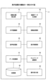
図5は、音声処理の流れの一例を示すシーケンス図である。 Figure 5 is a sequence diagram showing an example of the flow of audio processing.
ユーザの操作によってペン2500のペン先が表示装置2のディスプレー220にタッチすると(ステップS101)、接触処理部24は、接触位置検出部21によって検出された接触位置におけるタッチ操作(第一のタッチ操作)を検知する。すると、接触処理部24は、音声認識機能についての動作モードを音声認識ONモードに切り替える。
When the tip of the
接触処理部24は、音声認識機能についての動作モードを音声認識ONモードに切り替えたこと(すなわち、音声認識の開始)を、接触位置を示す情報とともに音声処理部25に通知する(ステップS102)。音声処理部25は、音声認識開始の通知を受けると、データ記録部27を介して、接触位置を示す情報を文字の表示を開始する開始座標として記憶部30に保存する(ステップS103)。
The
次に、接触処理部24は、訂正機能についての動作モードを訂正ONモードに切り替える(ステップS104)。そして、接触処理部24は、音声認識ONモードおよび訂正ONモードの開始から一定時間(TaおよびTb)の経過を検知するために、タイマーをスタートさせる(ステップS105)。
Next, the
次に、音声処理部25は、ユーザからの音声の入力を受けると(ステップS106)、音声認識処理を実行して、文字に変換する。ここで、音声処理部25は、音声認識によって文節または単語の区切り位置と、各文節または単語に変換する文字の候補とを、データ記録部27を介して記憶部30に記憶させる。記憶させる文字の候補は、第一候補だけでなく、第二候補、第三候補等も含むことが望ましい。
Next, when the
そして、音声処理部25は、変換された文字を表示制御部26に引き渡して、描画を依頼する(ステップS107)。表示制御部26は、ディスプレー220において、記憶部30に保存された開始座標の位置に、引き渡された文字を表示する制御を行う(ステップS108)。
Then, the
音声処理部25および表示制御部26は、ユーザからの音声の入力を受けるたびに、ステップS106-S108と同様の処理を実行する(ステップS109-S111)。
The
タイマーが一定時間(Ta)の経過を検知すると、音声処理部25は、音声認識機能についての動作モードを音声認識OFFモードに切り替える(ステップS112)。なお、TaおよびTbはあらかじめ設定され、Ta<Tbに設定されている。したがって、ここでは訂正機能についての動作モードは、訂正OFFモードには切り替えられていない。
When the timer detects that a certain period of time (Ta) has elapsed, the
次に、ユーザの操作によってペン2500のペン先がディスプレー220の描画された文字にタッチすると(ステップS113)、接触処理部24は、接触位置検出部21によって検出された接触位置におけるタッチ操作(第二のタッチ操作)を検知する。そして、接触処理部24は、接触位置検出部21によって検出された接触位置に描画された文字の訂正処理の開始を音声処理部25に依頼する(ステップS114)。
Next, when the user touches the tip of the
音声処理部25は、ペン2500のペン先がタッチした位置に表示されている文字を含む単語を訂正箇所とする。なお、音声処理部25は、他の方法によって訂正箇所を特定しても良い。例えば、ペン2500のペン先によって書き込まれた線(取り消し線)の位置に表示されている単語を訂正箇所としても良い。また、ペン2500のペン先によって書き込まれた線に囲まれた領域に表示されている単語を訂正箇所としても良い。
The
なお、音声処理部25は、音声認識の際に記憶部30に記憶させた文節または単語の区切り位置に基づいて、単語または文節の切れ目を決定する。例えば、「じゅうようじこうのせつめい」という音声の入力に対して、音声認識の際に「じゅうよう」、「じこう」、「の」および「せつめい」という単語の区切り位置を記憶している場合、記憶されている区切り位置に基づいて、「じゅうよう」という単語を訂正箇所とする。
The
なお、音声処理部25は、他の方法によって単語または文節の切れ目を決定しても良い。例えば、音声処理部25は、タッチされた文字を中心にして、例えば1文字から4文字程度の文字を含む文字列が単語として適切か否かを判定することによって、単語の切れ目を決定しても良い。例えば、「じゅうよう」の「よ」がタッチされた文字である場合、音声処理部25は、「よう」、「うよ」、「うよう」、「じゅうよう」等の切り目の候補の中から、単語として適切な単語「じゅうよう」を1単語とする切れ目に決定しても良い。
The
次に、音声処理部25は、訂正候補を表示制御部26に引き渡して表示を依頼する(ステップS115)。なお、音声処理部25は、音声認識の際に記憶部30に記憶させた文字の候補のうち、現在表示中のもの(通常は第一候補)以外の候補(例えば第二候補、第三候補等)を訂正候補とする。例えば、音声認識の際に、「重量」を第一候補、「重要」を第二候補、「従量」を第三候補、「中量」を第四候補にそれぞれ決定されていたことを示す情報が、記憶部30によって記憶されている場合、音声処理部25は、これらのうち、訂正対象である第一候補の「重量」を除く、「重要」、「従量」および「中量」を訂正候補とする。また、音声処理部25は、他の方法によって訂正候補を決定しても良い。例えば、音声処理部25は、切れ目が決定された単語または文節に近い単語または文節を、音声認識エンジンを使用して出力しても良い。
Next, the
表示制御部26は、引き渡された訂正候補を表示する制御を行う(ステップS116)。
The
次に、ユーザの操作によってペン2500のペン先がディスプレー220の描画された訂正候補にタッチすると(ステップS117)、接触処理部24は、接触位置検出部21によって検出された接触位置におけるタッチ操作(第三のタッチ操作)を検知する。接触処理部24は、接触位置検出部21によって検出された接触位置に描画された訂正候補への選択完了を音声処理部25に通知する(ステップS118)。
Next, when the user operates the pen tip of the
音声処理部25は、訂正された文字列を表示制御部26に引き渡して描画を依頼する(ステップS119)。表示制御部26は、引き渡された文字列を描画する制御を行う(ステップS120)。
The
タイマーが一定時間(Tb)の経過を検知すると、接触処理部24は、訂正機能についての動作モードを訂正OFFモードに切り替える(ステップS121)。
When the timer detects that a certain period of time (Tb) has elapsed, the
図6は、音声処理に係る表示画面の一例を示す第一の図である。 Figure 6 is a first diagram showing an example of a display screen related to audio processing.
図6(a)は、ペン2500のペン先が音声入力開始位置をタッチした状態(図5;ステップS101)のディスプレー220を示している。図6(b)は、音声入力「重要事項の説明」という音声が入力された状態(図5;ステップS106)のディスプレー220を示している。なお、ディスプレー220には、音声認識処理の結果、「重要」ではなく「重量」と表示されている。
Figure 6 (a) shows the
図6(c)は、ペン2500のペン先が訂正箇所をタッチした状態(図5;ステップS113)のディスプレー220を示している。図6(d)は、訂正候補が表示された状態(図5;ステップS116)のディスプレー220を示している。図6(e)は、訂正が完了した状態(図5;ステップS120)のディスプレー220を示している。
Figure 6(c) shows the
本実施形態に係る表示装置2によれば、音声処理部25は、画面への第一のタッチ操作が検出されると、音声の入力を受け付けて、入力された音声を音声認識によって文字に変換する。これによって、簡単な操作で音声認識を開始することができる。また、表示制御部26は、画面における第一のタッチ操作を受けた位置に、変換された文字を表示する制御を行う。これによって、簡単な操作によって、音声認識の結果を表示する箇所を指定することができる。
According to the
さらに、本実施形態に係る表示装置2によれば、音声処理部25は、音声認識によって表示された文字への第二のタッチ操作が検出されると、第二のタッチ操作を文字の訂正操作として受け付ける。これによって、簡単な操作によって、音声認識の結果を訂正することができる。
Furthermore, in the
タッチ操作を長押し操作と区別する場合において、タッチ操作は、長押し操作よりも素早く反応が得られる操作であり、上述した各操作は、直感的な操作である。したがって、音声認識による文字表示における操作性を向上させることができる。 When distinguishing between a touch operation and a long press operation, a touch operation is an operation that can obtain a quicker response than a long press operation, and each of the above-mentioned operations is an intuitive operation. Therefore, it is possible to improve the operability in displaying characters by voice recognition.
なお、訂正ONモードは一定時間(Tb)の経過によって終了する。これによって、上述したタッチ操作を訂正として扱う時間を、当該操作を行う可能性が高い時間に限定させることができる。仮に、このような限定を行わない場合には、新たな文字入力を行いたい場合にも、訂正として扱われてしまう可能性が高くなる。これによって、操作性をさらに向上させることができる。 The correction ON mode ends after a certain period of time (Tb) has elapsed. This makes it possible to limit the time during which the above-mentioned touch operation is treated as a correction to a time when such an operation is likely to be performed. If such a limitation were not imposed, even when a new character is to be input, there is a high possibility that the operation will be treated as a correction. This makes it possible to further improve operability.
なお、音声処理部25は、音声認識による文節の区切りの検知、または音声が途切れてから一定時間の経過等により、音声認識機能についての動作モードを音声認識OFFモードに切り替えるようにしても良い。
The
また、接触処理部24は、音声認識ONモードから音声認識OFFモードに切り替わってから一定時間の経過または音声認識によって変換された文字の量に応じた時間の経過により、訂正機能についての動作モードを訂正OFFモードに切り替えるようにしても良い。
The
また、表示装置2は、訂正OFFモードへの切り替えまたは音声認識OFFモードへの切り替えを示すメニュー等を表示して、ユーザの明示的な操作によって、切り替えるようにしても良い。
The
図7は、音声処理に係る表示画面の一例を示す第二の図である。 Figure 7 is a second diagram showing an example of a display screen related to audio processing.
図7(d)に示すように、音声処理部25は、図5のステップS115の処理において、訂正候補を表示する代わりに、手書き入力を受け付けるための枠線を表示する制御を表示制御部26に依頼しても良い。この場合、手書き入力を受け付けると、文字認識部23は、入力された手書きデータから文字を認識して、訂正後の文字として表示する制御を表示制御部26に依頼する。
As shown in FIG. 7(d), in the process of step S115 in FIG. 5, the
図8は、音声処理に係る表示画面の一例を示す第三の図である。 Figure 8 is a third diagram showing an example of a display screen related to audio processing.
図8(d)に示すように、音声処理部25は、図5のステップS115の処理において、訂正候補を表示する代わりに、音声での入力を受け付ける。この場合、音声での入力を受け付けると、音声処理部25は、入力された音声に対する音声認識処理を実行して、訂正後の文字として表示する制御を表示制御部26に依頼するとともに、記憶部30に記憶させる。
As shown in FIG. 8(d), in the process of step S115 in FIG. 5, the
図9は、表示装置の他の構成例を示す第一の図である。 Figure 9 is a first diagram showing another example configuration of a display device.
図9では、通常のホワイトボード413の上辺にプロジェクタ411が設置されている。このプロジェクタ411が表示装置2に相当する。通常のホワイトボード413とは、タッチパネルと一体のフラットパネルディスプレーではなく、ユーザがマーカーで直接、手書きするホワイトボードである。なお、ホワイトボードは黒板でもよく、映像を投影するだけの広さの平面であればよい。
In FIG. 9, a
プロジェクタ411は超短焦点の光学系を有しており、10cm程度から歪みの少ない映像をホワイトボード413に投影できる。この映像は、無線又は有線で接続されたPC400-1から送信されてもよいし、プロジェクタ411が記憶していてもよい。
ユーザは専用の電子ペン2501を使ってホワイトボード413に手書きする。電子ペン2501は、ユーザが手書きのためにホワイトボード413に押しつけるとスイッチがONになり発光する発光部を例えば先端部に有している。光の波長は近赤外や赤外なのでユーザの目には見えない。プロジェクタ411はカメラを有しており、発光部を撮像して画像を解析し電子ペン2501の方向を特定する。また、電子ペン2501は発光と共に音波を発信しており、プロジェクタ411は音波の到達時間により距離を算出する。方向と距離により電子ペン2501の位置を特定できる。電子ペン2501の位置には手書きされたデータが描画(投影)される。
The user writes by hand on the
プロジェクタ411はメニュー430を投影するので、ユーザが電子ペン2501でボタンを押下すると、プロジェクタ411が電子ペン2501の位置とスイッチのON信号により押下されたボタンを特定する。例えば、保存ボタン431が押下されると、ユーザが手書きした手書きされたデータ(座標点列)がプロジェクタ411で保存される。プロジェクタ411は、予め定められたサーバ412又はUSBメモリ2600等に手書き情報を保存する。手書き情報はページごとに保存されている。画像データではなく座標のまま保存されるので、ユーザが再編集することができる。ただし、本実施形態では操作コマンドを手書きで呼び出せるのでメニュー430は表示されなくてもよい。
The
図10は、表示装置の他の構成例を示す第二の図である。 Figure 10 is a second diagram showing another example configuration of a display device.
表示装置2として、端末装置600、画像投影装置700A、及び、ペン動作検出装置810を有する。
The
端末装置600は、画像投影装置700A及びペン動作検出装置810と有線で接続されている。画像投影装置700Aは、端末装置600により入力された画像データをスクリーン800に投影させる。
The
ペン動作検出装置810は、電子ペン820と通信を行っており、スクリーン800の近傍における電子ペン820の動作を検出する。具体的には、電子ペン820は、スクリーン800上において、電子ペン820が示している点を示す座標情報を検出し(検出方法は図9と同様でよい)、端末装置600へ送信する。
The pen
端末装置600は、ペン動作検出装置810から受信した座標情報に基づき、電子ペン820によって入力される手書きデータの画像データを生成し、画像投影装置700Aによって手書きデータの画像をスクリーン800に描画させる。
Based on the coordinate information received from the pen
また、端末装置600は、画像投影装置700Aに投影させている背景画像と、電子ペン820によって入力された手書きデータの画像とを合成した重畳画像を示す重畳画像データを生成する。
In addition, the
図11は、表示装置の他の構成例を示す第三の図である。 Figure 11 is a third diagram showing another example configuration of a display device.
図11の例では、表示装置2として、端末装置600と、ディスプレー800Aと、ペン動作検出装置810とを有する。
In the example of FIG. 11, the
ペン動作検出装置810は、ディスプレー800Aの近傍に配置され、ディスプレー800A上に、電子ペン820Aが示している点を示す座標情報を検出し(検出方法は図26と同様でよい)、端末装置600へ送信する。なお、図28の例では、電子ペン820Aは、端末装置600によってUSBコネクタを介して充電されても良い。
The pen
端末装置600は、ペン動作検出装置810から受信した座標情報に基づき、電子ペン820Aによって入力される手書きデータの画像を示す画像データを生成し、ディスプレー800Aに表示させる。
Based on the coordinate information received from the pen
図12は、表示装置の他の構成例を示す第四の図である。 Figure 12 is a fourth diagram showing another example configuration of a display device.
図12の例では、表示装置2として、端末装置600と、画像投影装置700Aとを有する。
In the example of FIG. 12, the
端末装置600は、電子ペン820Bと無線通信(Bluetooth(登録商標)等)を行って、スクリーン800上において電子ペン820Bが示す点の座標情報を受信する。座標情報は、スクリーン800に形成された微小な位置情報を電子ペン820Bが読み取ってもよいし、スクリーン800から座標情報を受信してもよい。
The
そして、端末装置600は、受信した座標情報に基づき、電子ペン820Bにより入力される手書きデータの画像の画像データを生成し、画像投影装置700Aに手書きデータの画像を投影させる。
Then, based on the received coordinate information, the
また、端末装置600は、画像投影装置700Aに投影させている背景画像と、電子ペン820によって入力された手書きデータの画像とを合成した重畳画像を示す重畳画像データを生成する。
In addition, the
以上のように、上記した各実施形態は、様々なシステム構成において適用することができる。 As described above, each of the above-mentioned embodiments can be applied to various system configurations.
以上、本発明を実施するための最良の形態について実施例を用いて説明したが、本発明はこうした実施例に何等限定されるものではなく、本発明の要旨を逸脱しない範囲内において種々の変形及び置換を加えることができる。 The above describes the best mode for carrying out the present invention using examples, but the present invention is not limited to these examples, and various modifications and substitutions can be made without departing from the spirit of the present invention.
文字列は文字コードとして、手書きデータは座標点データとして表示装置2に保存される。また、各種の記憶媒体に保存したり、ネットワーク上の記憶装置に保存したりしておいて、後で、表示装置2からダウンロードして再使用することができる。再使用する表示装置2はどの表示装置でもよく、一般的な情報処理装置でもよい。したがって、ユーザは手書きした内容を異なる表示装置2で再現して会議などを継続することができる。
The character string is stored as character codes, and the handwritten data is stored as coordinate point data on the
また、本実施形態ではペン先の座標をタッチパネルで検知する方法でペンの座標を検出したが、ペン先の座標を超音波により検出してもよい。また、ペンは発光と共に超音波を発信しており、表示装置2は超音波の到達時間により距離を算出する。方向と距離によりペンの位置を特定できる。ペンの軌跡をストロークデータとしてプロジェクタが描画(投影)する。
In this embodiment, the coordinates of the pen are detected by detecting the coordinates of the pen tip using a touch panel, but the coordinates of the pen tip may also be detected using ultrasonic waves. The pen emits light and also emits ultrasonic waves, and the
また、図4などの構成例は、表示装置2による処理の理解を容易にするために、主な機能に応じて分割したものである。処理単位の分割の仕方や名称によって本願発明が制限されることはない。表示装置2の処理は、処理内容に応じて更に多くの処理単位に分割することもできる。また、1つの処理単位が更に多くの処理を含むように分割することもできる。
The configuration examples in FIG. 4 and the like are divided according to the main functions to make it easier to understand the processing by the
また、表示装置2が行う処理の一部を、表示装置2とネットワークを介して接続されたサーバが行ってもよい。
In addition, some of the processing performed by the
上記で説明した実施形態の各機能は、一又は複数の処理回路によって実現することが可能である。ここで、本明細書における「処理回路」とは、電子回路により実装されるプロセッサのようにソフトウェアによって各機能を実行するようプログラミングされたプロセッサや、上記で説明した各機能を実行するよう設計されたASIC(Application Specific Integrated Circuit)、DSP(Digital Signal Processor)、FPGA(Field Programmable Gate Array)や従来の回路モジュール等のデバイスを含むものとする。 Each function of the embodiments described above can be realized by one or more processing circuits. In this specification, the term "processing circuit" includes a processor programmed to execute each function by software, such as a processor implemented by an electronic circuit, and devices such as an ASIC (Application Specific Integrated Circuit), DSP (Digital Signal Processor), FPGA (Field Programmable Gate Array), and conventional circuit modules designed to execute each function described above.
上記で説明した実施形態の各機能は、表示装置2の備えるCPU201の動作を規定するOS(Operating system)上で動作するアプリケーションプログラムによって実現され得る。
The functions of the above-described embodiments can be realized by application programs that run on an OS (Operating system) that defines the operation of the
尚、本実施形態が適用される装置は、タッチ操作によって、オブジェクトを操作する機能を備えた表示装置であれば良く、電子黒板に限定されにない。本実施形態が適用される表示装置は、例えば、PJ(Projector:プロジェクタ)、デジタルサイネージ等の出力装置、HUD(Head Up Display)装置、ネットワーク家電、自動車(Connected Car)、ノートPC(Personal Computer)、携帯電話、スマートフォン、タブレット端末、ゲーム機、PDA(Personal Digital Assistant)、ウェアラブルPC等であってもよい。 The device to which this embodiment is applied may be any display device equipped with a function for operating objects by touch operation, and is not limited to electronic whiteboards. The display device to which this embodiment is applied may be, for example, a PJ (Projector), an output device such as digital signage, a HUD (Head Up Display) device, a network home appliance, an automobile (Connected Car), a notebook PC (Personal Computer), a mobile phone, a smartphone, a tablet terminal, a game console, a PDA (Personal Digital Assistant), a wearable PC, etc.
以上、各実施形態に基づき本発明の説明を行ってきたが、上記実施形態に示した要件に本発明が限定されるものではない。これらの点に関しては、本発明の主旨をそこなわない範囲で変更することができ、その応用形態に応じて適切に定めることができる。 The present invention has been described above based on each embodiment, but the present invention is not limited to the requirements shown in the above embodiments. These points can be changed without departing from the spirit of the present invention, and can be appropriately determined according to the application form.
2 表示装置
21 接触位置検出部
22 描画データ生成部
23 文字認識部
24 接触処理部
25 音声処理部
26 表示制御部
27 データ記録部
28 ネットワーク通信部
29 操作受付部
30 記憶部
2
Claims (6)
前記画面における前記第一のタッチ操作を受けた位置に、変換された前記文字を表示する制御を行う表示制御部と、を備え、
前記音声処理部は、前記音声認識によって表示された文字への第二のタッチ操作が検出されると、前記第二のタッチ操作を前記文字の訂正操作として受け付け、前記画面への第一のタッチ操作が検出されると、訂正機能についての動作モードを訂正ONモードに切り替え、前記訂正機能についての動作モードが前記訂正ONモードである場合に、前記音声認識によって表示された文字への前記第二のタッチ操作が検出されると、前記第二のタッチ操作を前記文字の訂正操作として受け付け、訂正ONモードの開始から一定時間が経過すると、訂正機能についての動作モードを訂正OFFモードに切り替える、
表示装置。 a voice processing unit that receives a voice input and converts the input voice into text by voice recognition when a first touch operation on the screen is detected;
a display control unit that performs control to display the converted character at a position on the screen where the first touch operation is received,
When a second touch operation on a character displayed by the voice recognition is detected, the voice processing unit accepts the second touch operation as a correction operation of the character , and when a first touch operation on the screen is detected, the voice processing unit switches an operation mode for a correction function to a correction ON mode, and when the operation mode for the correction function is the correction ON mode, when the second touch operation on a character displayed by the voice recognition is detected, the voice processing unit accepts the second touch operation as a correction operation of the character, and when a certain time has elapsed since the start of the correction ON mode, switches the operation mode for the correction function to a correction OFF mode.
Display device.
請求項1に記載の表示装置。 when a second touch operation on the character displayed by the voice recognition is detected, the display control unit displays a correction candidate for the character.
The display device according to claim 1 .
請求項1に記載の表示装置。 when a second touch operation on the character displayed by the voice recognition is detected, the voice processing unit accepts a handwritten input as a correction to the character.
The display device according to claim 1 .
請求項1に記載の表示装置。 when a second touch operation on the character displayed by the voice recognition is detected, the voice processing unit accepts a voice input as a correction to the character and converts it into the corrected character by voice recognition.
The display device according to claim 1 .
画面への第一のタッチ操作が検出されると、音声の入力を受け付けて、入力された音声を音声認識によって文字に変換するステップと、
前記画面における前記第一のタッチ操作を受けた位置に、変換された前記文字を表示する制御を行うステップと、
前記音声認識によって表示された文字への第二のタッチ操作が検出されると、前記第二のタッチ操作を前記文字の訂正操作として受け付け、前記画面への第一のタッチ操作が検出されると、訂正機能についての動作モードを訂正ONモードに切り替え、前記訂正機能についての動作モードが前記訂正ONモードである場合に、前記音声認識によって表示された文字への前記第二のタッチ操作が検出されると、前記第二のタッチ操作を前記文字の訂正操作として受け付け、訂正ONモードの開始から一定時間が経過すると、訂正機能についての動作モードを訂正OFFモードに切り替えるステップと、を備える、
表示方法。 1. A computer-implemented method comprising:
receiving a voice input when a first touch operation on the screen is detected, and converting the input voice into text by voice recognition;
performing control to display the converted character at a position on the screen where the first touch operation is received;
when a second touch operation on a character displayed by the voice recognition is detected, the second touch operation is accepted as a correction operation of the character ; when a first touch operation on the screen is detected, an operation mode for a correction function is switched to a correction ON mode; when the operation mode for the correction function is the correction ON mode, when the second touch operation on a character displayed by the voice recognition is detected, the second touch operation is accepted as a correction operation of the character; and when a certain time has elapsed since the start of the correction ON mode, the operation mode for the correction function is switched to a correction OFF mode .
Display method.
画面への第一のタッチ操作が検出されると、音声の入力を受け付けて、入力された音声を音声認識によって文字に変換するステップと、
前記画面における前記第一のタッチ操作を受けた位置に、変換された前記文字を表示する制御を行うステップと、
前記音声認識によって表示された文字への第二のタッチ操作が検出されると、前記第二のタッチ操作を前記文字の訂正操作として受け付け、前記画面への第一のタッチ操作が検出されると、訂正機能についての動作モードを訂正ONモードに切り替え、前記訂正機能についての動作モードが前記訂正ONモードである場合に、前記音声認識によって表示された文字への前記第二のタッチ操作が検出されると、前記第二のタッチ操作を前記文字の訂正操作として受け付け、訂正ONモードの開始から一定時間が経過すると、訂正機能についての動作モードを訂正OFFモードに切り替えるステップと、
を実行させるためのプログラム。 On the computer,
receiving a voice input when a first touch operation on the screen is detected, and converting the input voice into text by voice recognition;
performing control to display the converted character at a position on the screen where the first touch operation is received;
when a second touch operation on a character displayed by the voice recognition is detected, accepting the second touch operation as a correction operation of the character ; when a first touch operation on the screen is detected, switching an operation mode for a correction function to a correction ON mode; when the operation mode for the correction function is the correction ON mode, when the second touch operation on a character displayed by the voice recognition is detected, accepting the second touch operation as a correction operation of the character; and when a certain time has elapsed since the start of the correction ON mode, switching the operation mode for the correction function to a correction OFF mode ;
A program for executing the above.
Priority Applications (1)
| Application Number | Priority Date | Filing Date | Title |
|---|---|---|---|
| JP2021016604A JP7596830B2 (en) | 2021-02-04 | 2021-02-04 | Display device, display method, and program |
Applications Claiming Priority (1)
| Application Number | Priority Date | Filing Date | Title |
|---|---|---|---|
| JP2021016604A JP7596830B2 (en) | 2021-02-04 | 2021-02-04 | Display device, display method, and program |
Publications (2)
| Publication Number | Publication Date |
|---|---|
| JP2022119463A JP2022119463A (en) | 2022-08-17 |
| JP7596830B2 true JP7596830B2 (en) | 2024-12-10 |
Family
ID=82848177
Family Applications (1)
| Application Number | Title | Priority Date | Filing Date |
|---|---|---|---|
| JP2021016604A Active JP7596830B2 (en) | 2021-02-04 | 2021-02-04 | Display device, display method, and program |
Country Status (1)
| Country | Link |
|---|---|
| JP (1) | JP7596830B2 (en) |
Citations (4)
| Publication number | Priority date | Publication date | Assignee | Title |
|---|---|---|---|---|
| US20140163983A1 (en) | 2012-12-10 | 2014-06-12 | Lg Electronics Inc. | Display device for converting voice to text and method thereof |
| JP2014149612A (en) | 2013-01-31 | 2014-08-21 | Nippon Hoso Kyokai <Nhk> | Voice recognition error correction device and its program |
| JP2019149080A (en) | 2018-02-28 | 2019-09-05 | シャープ株式会社 | Information processing apparatus, information processing method, and program |
| WO2020115909A1 (en) | 2018-12-07 | 2020-06-11 | 三菱電機株式会社 | Input display control device, input display control method, and input display system |
-
2021
- 2021-02-04 JP JP2021016604A patent/JP7596830B2/en active Active
Patent Citations (4)
| Publication number | Priority date | Publication date | Assignee | Title |
|---|---|---|---|---|
| US20140163983A1 (en) | 2012-12-10 | 2014-06-12 | Lg Electronics Inc. | Display device for converting voice to text and method thereof |
| JP2014149612A (en) | 2013-01-31 | 2014-08-21 | Nippon Hoso Kyokai <Nhk> | Voice recognition error correction device and its program |
| JP2019149080A (en) | 2018-02-28 | 2019-09-05 | シャープ株式会社 | Information processing apparatus, information processing method, and program |
| WO2020115909A1 (en) | 2018-12-07 | 2020-06-11 | 三菱電機株式会社 | Input display control device, input display control method, and input display system |
Also Published As
| Publication number | Publication date |
|---|---|
| JP2022119463A (en) | 2022-08-17 |
Similar Documents
| Publication | Publication Date | Title |
|---|---|---|
| US11250253B2 (en) | Handwriting input display apparatus, handwriting input display method and recording medium storing program | |
| JP2025026538A (en) | Display device, display method, and program | |
| CN113961061A (en) | Display device, control method, storage medium, and information processing device | |
| JP7615805B2 (en) | Display device, program, display method, and display system | |
| US20230043998A1 (en) | Display apparatus, information processing method, and recording medium | |
| WO2022071448A1 (en) | Display apparatus, display method, and program | |
| JP7786523B2 (en) | Input device, input method, and program | |
| JP7596830B2 (en) | Display device, display method, and program | |
| US20230070034A1 (en) | Display apparatus, non-transitory recording medium, and display method | |
| JP2021197024A (en) | Display unit, display method, and program | |
| TW201423563A (en) | Apparatus and method for processing handwriting input | |
| JP7615790B2 (en) | Display device, display method, and program | |
| JP7508916B2 (en) | Display device, display method, and program | |
| JP7392315B2 (en) | Display device, display method, program | |
| JP7604974B2 (en) | Display device, display method, and program | |
| JP7619115B2 (en) | Display device, display method, and program | |
| JP7480608B2 (en) | Display device, display method, and program | |
| JP7739733B2 (en) | Display device, display method, program, and display system | |
| JP7615810B2 (en) | Display device, display method, and program | |
| JP7351374B2 (en) | Display device, display program, display method | |
| JP7268479B2 (en) | Display device, program, display method | |
| JP7388153B2 (en) | Display device, display program, display method | |
| JP7494506B2 (en) | Display device, display method, and program | |
| JP2023133110A (en) | Display device, display method, and program | |
| JP2023137822A (en) | Display device, fair copy method, program, and information sharing system |
Legal Events
| Date | Code | Title | Description |
|---|---|---|---|
| A621 | Written request for application examination |
Free format text: JAPANESE INTERMEDIATE CODE: A621 Effective date: 20231212 |
|
| A977 | Report on retrieval |
Free format text: JAPANESE INTERMEDIATE CODE: A971007 Effective date: 20240617 |
|
| A131 | Notification of reasons for refusal |
Free format text: JAPANESE INTERMEDIATE CODE: A131 Effective date: 20240709 |
|
| A521 | Request for written amendment filed |
Free format text: JAPANESE INTERMEDIATE CODE: A523 Effective date: 20240814 |
|
| TRDD | Decision of grant or rejection written | ||
| A01 | Written decision to grant a patent or to grant a registration (utility model) |
Free format text: JAPANESE INTERMEDIATE CODE: A01 Effective date: 20241029 |
|
| A61 | First payment of annual fees (during grant procedure) |
Free format text: JAPANESE INTERMEDIATE CODE: A61 Effective date: 20241111 |
|
| R150 | Certificate of patent or registration of utility model |
Ref document number: 7596830 Country of ref document: JP Free format text: JAPANESE INTERMEDIATE CODE: R150 |