JP7592012B2 - Method for manufacturing a ceramic dental prosthetic part - Patent application - Google Patents
Method for manufacturing a ceramic dental prosthetic part - Patent application Download PDFInfo
- Publication number
- JP7592012B2 JP7592012B2 JP2021526495A JP2021526495A JP7592012B2 JP 7592012 B2 JP7592012 B2 JP 7592012B2 JP 2021526495 A JP2021526495 A JP 2021526495A JP 2021526495 A JP2021526495 A JP 2021526495A JP 7592012 B2 JP7592012 B2 JP 7592012B2
- Authority
- JP
- Japan
- Prior art keywords
- blank
- grinding tool
- cad
- recess
- adapter
- Prior art date
- Legal status (The legal status is an assumption and is not a legal conclusion. Google has not performed a legal analysis and makes no representation as to the accuracy of the status listed.)
- Active
Links
Images


Classifications
-
- A—HUMAN NECESSITIES
- A61—MEDICAL OR VETERINARY SCIENCE; HYGIENE
- A61C—DENTISTRY; APPARATUS OR METHODS FOR ORAL OR DENTAL HYGIENE
- A61C13/00—Dental prostheses; Making same
- A61C13/0003—Making bridge-work, inlays, implants or the like
- A61C13/0004—Computer-assisted sizing or machining of dental prostheses
-
- A—HUMAN NECESSITIES
- A61—MEDICAL OR VETERINARY SCIENCE; HYGIENE
- A61C—DENTISTRY; APPARATUS OR METHODS FOR ORAL OR DENTAL HYGIENE
- A61C13/00—Dental prostheses; Making same
- A61C13/0003—Making bridge-work, inlays, implants or the like
- A61C13/0006—Production methods
-
- A—HUMAN NECESSITIES
- A61—MEDICAL OR VETERINARY SCIENCE; HYGIENE
- A61C—DENTISTRY; APPARATUS OR METHODS FOR ORAL OR DENTAL HYGIENE
- A61C13/00—Dental prostheses; Making same
- A61C13/0003—Making bridge-work, inlays, implants or the like
- A61C13/0022—Blanks or green, unfinished dental restoration parts
-
- A—HUMAN NECESSITIES
- A61—MEDICAL OR VETERINARY SCIENCE; HYGIENE
- A61C—DENTISTRY; APPARATUS OR METHODS FOR ORAL OR DENTAL HYGIENE
- A61C13/00—Dental prostheses; Making same
- A61C13/08—Artificial teeth; Making same
- A61C13/083—Porcelain or ceramic teeth
-
- A—HUMAN NECESSITIES
- A61—MEDICAL OR VETERINARY SCIENCE; HYGIENE
- A61C—DENTISTRY; APPARATUS OR METHODS FOR ORAL OR DENTAL HYGIENE
- A61C5/00—Filling or capping teeth
- A61C5/70—Tooth crowns; Making thereof
- A61C5/77—Methods or devices for making crowns
Landscapes
- Health & Medical Sciences (AREA)
- Animal Behavior & Ethology (AREA)
- Veterinary Medicine (AREA)
- Public Health (AREA)
- Oral & Maxillofacial Surgery (AREA)
- Dentistry (AREA)
- Epidemiology (AREA)
- Life Sciences & Earth Sciences (AREA)
- General Health & Medical Sciences (AREA)
- Engineering & Computer Science (AREA)
- Manufacturing & Machinery (AREA)
- Ceramic Engineering (AREA)
- Chemical & Material Sciences (AREA)
- Dental Prosthetics (AREA)
- Grinding And Polishing Of Tertiary Curved Surfaces And Surfaces With Complex Shapes (AREA)
- Dental Tools And Instruments Or Auxiliary Dental Instruments (AREA)
Description
関連出願への相互参照
この特許出願は、あらゆる目的で参照により本明細書に組み込まれる、2018年11月15日に出願されたEP特許出願第18206460.0号の利益及び優先権を主張するものである。
CROSS-REFERENCE TO RELATED APPLICATIONS This patent application claims the benefit of and priority to EP Patent Application No. 18206460.0, filed November 15, 2018, which is incorporated herein by reference for all purposes.
本発明は、CAD/CAM機械加工ステーションによってセラミック歯科補綴部品を製造するための方法、対応するCAD/CAM機械加工ステーション、及びCAD/CAM機械加工ステーションを制御するためのコンピュータプログラム、並びに最終強度の歯科用セラミックで作製された円盤形ブランクに関する。 The present invention relates to a method for manufacturing ceramic dental prosthetic parts by means of a CAD/CAM machining station, a corresponding CAD/CAM machining station, a computer program for controlling the CAD/CAM machining station, and a disk-shaped blank made of final strength dental ceramic.
焼結されていない形態又は最終的な焼結がまだ行われていない形態で存在する円盤形ブランクが加工される、歯科修復物の製造方法が、WO2004/086999A1から公知である。この既に知られている方法によれば、最終強度のブランクを加工することはできない。 A method for manufacturing dental restorations is known from WO 2004/086999 A1, in which a disk-shaped blank is processed that is present in an unsintered form or in a form in which the final sintering has not yet taken place. With this already known method, it is not possible to process a blank in its final strength.
対照的に、本発明の目的は、セラミック歯科補綴部品を製造するための改良された方法、及び対応するCAD/CAM機械加工ステーション、コンピュータプログラム、及びブランクをもたらすことである。 In contrast, the object of the present invention is to provide an improved method for manufacturing ceramic dental prosthetic components, and corresponding CAD/CAM machining stations, computer programs, and blanks.
本発明の根底にある目的は、独立請求項の特徴によって達成される。本発明の実施形態は、従属請求項で説明される。 The object underlying the present invention is achieved by the features of the independent claims. Embodiments of the invention are described in the dependent claims.
本明細書での「歯科補綴部品」は、修復歯科医学分野でのクラウン又はブリッジなどのセラミック歯科補綴物を意味すると理解されるものとする。 In this specification, "dental prosthetic part" shall be understood to mean a ceramic dental prosthesis such as a crown or bridge in the field of restorative dentistry.
本明細書での「円盤形のセラミックブランク」は、特に、例えば、円筒形、特に円柱形、平円盤形、又は長方形の輪郭、或いは人間の顎に似た輪郭を有することができる、いわゆる円形ブランクを意味すると理解されるものとする(https://www.amanngirrbach.com/index.php?id=23&news=UWC9bNZ4&no_cache=1&L=2参照)。本明細書で理解される「円盤形のセラミックブランク」はまた、円形、長方形、三角形、又は他の多角形、或いは湾曲した又は楕円形の周縁を有し得る、円盤形、プレート形、又はスライス形のセラミックブランクを包含し、これは、プレス嵌め及び/又はフォームフィットにより、その周縁がマウント装置によって解放可能に保持されるように構成される。 A "disc-shaped ceramic blank" in this specification is to be understood to mean in particular a so-called circular blank, which may have, for example, a cylindrical, in particular cylindrical, disk-shaped or rectangular contour, or a contour resembling a human jaw (see https://www.amannngirrbach.com/index.php?id=23&news=UWC9bNZ4&no_cache=1&L=2). A "disc-shaped ceramic blank" as understood in this specification also encompasses a disk-, plate- or slice-shaped ceramic blank, which may have a circular, rectangular, triangular or other polygonal, or curved or elliptical periphery, which is configured to be releasably held by the mounting device at its periphery by press-fitting and/or form-fitting.
例えばDE 20 2008 018 342 U1及びEP 2 016 922 B1から公知の「サブブランク84」と呼ばれるブロック形のブランクとは対照的に、本発明に係るこのような円盤形のセラミックブランクは、CAD/CAM機械加工ステーションのマウント装置によってその周縁が囲まれることを意図されているため、ブランクに取り付けられたホルダ(EP 2 016 922 B1に「支持体86」として示される)を必要としない。
In contrast to the block-shaped blanks known, for example from DE 20 2008 018 342 U1 and
ブロック形のブランクに比べて、円盤形ブランクの特別な特徴は、機械加工の目的で円盤形ブランクがマウント装置に全周又はほぼ全周を囲まれていることであり、より具体的には、機械加工中に、一般に片側のみを、例えば接着して取り付けられたブロックホルダによって、取り付けられているブロック形のブランクとは対照的である。 A special feature of disk-shaped blanks, as compared to block-shaped blanks, is that for machining purposes the disk-shaped blanks are surrounded all around or almost all around by a mounting device, in contrast to block-shaped blanks, which are generally mounted during machining on only one side, for example by a glued-on block holder.
円盤形ブランクの使用は、メカニカルレバーがそれなりに高いので、例えば接着剤での片側での、ブロックホルダによる取り付けは不利であるというブロック形のブランクの欠点が回避されるため、歯科用ブリッジなどのロングスパンの補綴物に特に有利である。 The use of disk-shaped blanks is particularly advantageous for long-span prostheses such as dental bridges, since the disadvantage of block-shaped blanks, which have a relatively high mechanical lever and therefore are disadvantageous for mounting on one side, for example with adhesive, by means of a block holder, is avoided.
「円盤形のセラミックブランク」の場合、ブロック形のブランクとは対照的に、ブランクの厚さと直径の比は、1:1とは相当異なり、ブランクの厚さと直径の比は、例えば1:10から1:4の間の範囲であり得る。直径は、少なくとも40mmを超える、好ましくは90mmを超える、好ましくは200mm未満、特に95mmから110mmの間である。このようなブランクには、ホルダがない、つまり、接着剤結合などによってブランクにホルダが取り付けられておらず、ブランクは、マウント装置に好ましくは圧力嵌めで及び/又はフォームロック式にその周縁に沿って取り付けられることを意図されている。マウントは、全周に沿って行われてよく、又は周縁に沿った凹部によって間断されてもよい。 In the case of a "disc-shaped ceramic blank", in contrast to a block-shaped blank, the ratio of thickness to diameter of the blank is significantly different from 1:1, and the ratio of thickness to diameter of the blank may range, for example, between 1:10 and 1:4. The diameter is at least more than 40 mm, preferably more than 90 mm, preferably less than 200 mm, in particular between 95 mm and 110 mm. Such a blank is holder-free, i.e. no holder is attached to the blank, for example by adhesive bonding, and the blank is intended to be attached along its periphery, preferably by press-fit and/or form-locking, to a mounting device. The mounting may be along the entire circumference or may be interrupted by recesses along the periphery.
例えば、直径98.5mm、厚さ12、14、18、又は25mmの標準形態を有する円形ブランクが様々なセラミック材料で市販されている。しかしながら、円形ブランクは、105mmなどの異なる直径を有していてもよい。円形ブランクは、人間の上顎の形状に基づく輪郭などの非円形の形状を有していてもよい。 For example, circular blanks are commercially available in a variety of ceramic materials having a standard configuration of 98.5 mm diameter and 12, 14, 18, or 25 mm thickness. However, the circular blanks may have different diameters, such as 105 mm. The circular blanks may have a non-circular shape, such as a contour based on the shape of the human upper jaw.
本発明の実施形態によれば、ブランクは、CAD/CAM機械加工ステーションのマウント装置内にその周縁が囲まれるように取り付けられる。本明細書における「その周縁が囲まれる」とは、特に、包囲がブランクの全周、又は少なくとも1つの凹部を有するブランクの周縁の一部に沿って行われることを意味すると理解されるものとし、少なくとも1つの凹部は、ブランク及び/又はアダプタ及び/又はマウント装置に実装される可能性がある。 According to an embodiment of the invention, the blank is mounted in a mounting device of a CAD/CAM machining station so that it is surrounded around its periphery. In this specification, "surrounded around its periphery" is understood to mean in particular that the surrounding is along the entire periphery of the blank or along a part of the periphery of the blank that has at least one recess, which may be implemented in the blank and/or in the adapter and/or in the mounting device.
ブランクは、マウント装置に取り外し可能に囲まれており、包囲は、圧力嵌めで及び/又はフォームロック式に行われ得る。 The blank is removably enclosed in a mounting arrangement, and the enclosure may be press-fit and/or form-locked.
本明細書での「CAD/CAM機械加工ステーション」は、特に、歯科補綴部品を製造するべくブランクを機械加工するためのプログラムで制御されるマシンを意味すると理解されるものとする。 In this specification, "CAD/CAM machining station" is understood to mean, in particular, a program-controlled machine for machining blanks to produce dental prosthetic parts.
「研削ツール」は、特に、ミリングカッターとは対照的に、画定された回転切れ刃を含まないが研磨作業面によって形成される画定されていないブレードを含む、CAD/CAM機械加工ステーション用のツールを意味すると理解されるものとする。例えば、作業面は、特定の粒径を有するダイヤモンドなどの研磨粒子を含んでいてもよく、それにより、画定されていないブレードが形成される。 "Grinding tool" is to be understood to mean in particular a tool for a CAD/CAM machining station that, in contrast to a milling cutter, does not include a defined rotating cutting edge but an undefined blade formed by an abrasive working surface. For example, the working surface may include abrasive particles such as diamonds having a specific grain size, thereby forming an undefined blade.
本発明の実施形態は、円盤形のセラミックブランクの周縁がマウント装置に囲まれており、結果的に切削力に対するマウンティングの耐性が増すため、特に有利であり、これは、高い力及びトルクの下で接着が剥がれると機械加工中にホルダから落下する可能性があるブロックの機械加工に比べて有利である。 Embodiments of the invention are particularly advantageous because the peripheral edge of the disc-shaped ceramic blank is surrounded by a mounting arrangement, resulting in an increased resistance of the mounting to cutting forces, which is advantageous compared to machining blocks that may fall out of the holder during machining if the bond fails under high forces and torques.
本発明の実施形態は、最終強度のブランクからセラミック歯科補綴部品の直接の製造が可能となるので特に有利である。最新技術とは対照的に、製造する歯科補綴部品の寸法を指定するCADファイルを生成する際に、最終的な焼結に起因して生じる収縮を考慮に入れる必要はなく、CADファイルは、製造する歯科補綴部品の所望の最終寸法を直接示すことができる。 Embodiments of the invention are particularly advantageous since they allow the direct manufacture of ceramic dental prosthesis components from blanks of final strength. In contrast to the state of the art, when generating a CAD file specifying the dimensions of the dental prosthesis component to be manufactured, it is not necessary to take into account shrinkage resulting from final sintering, but the CAD file can directly indicate the desired final dimensions of the dental prosthesis component to be manufactured.
歯科補綴部品をブランクから機械加工した後の加工ステップ、すなわち、他の方法で必要とされる最終的な焼結が排除されるという点で、機械加工の複雑さも低減される。これは、実験室での適用といわゆるチェアサイドでの適用との両方に有利である。 The machining complexity is also reduced in that a processing step after machining the dental prosthetic part from the blank, i.e. the final sintering required with other methods, is eliminated. This is advantageous for both laboratory and so-called chairside applications.
別の利点は、ミリングの代わりに研削による機械加工を使用することにより、その幾何学的寸法に関して、特に表面粗さが小さいという点で精度が向上した歯科補綴部品の製造が可能となることである。 Another advantage is that the use of machining by grinding instead of milling allows the production of dental prosthetic components with improved precision in terms of their geometric dimensions, in particular with respect to reduced surface roughness.
機械加工後の焼結プロセスが排除される結果として、不正確な収縮率などの潜在的な誤差の原因が排除されることは、これに関してさらに有利であり得る。さらに、本発明の実施形態は、これをツールの交換なしに、すなわち研削ツールのみを使用して行うことができるので、特に有利である。 It may be further advantageous in this regard that potential sources of error such as inaccurate shrinkage rates are eliminated as a result of the elimination of the sintering process after machining. Moreover, embodiments of the present invention are particularly advantageous since this can be done without tool changes, i.e. using only grinding tools.
本発明の実施形態によれば、研削ツールの縦軸を中心とした回転によるブランクに対する運動が研削ツールとブランクとの間の接触面全体で起こるようにブランクと研削ツールとの最初の接触が確立されることで、最終強度のセラミックブランクの、ミリングではなく研削による機械加工が可能となる。 According to an embodiment of the invention, initial contact between the blank and the grinding tool is established such that motion relative to the blank due to rotation of the grinding tool about its longitudinal axis occurs across the entire interface between the grinding tool and the blank, allowing for machining of the ceramic blank to its final strength by grinding rather than milling.
言い換えれば、研削ツールは、最初に研磨作業面とブランクとの接触面が形成されるようにブランクに移動され、研削ツールの回転の中心となる縦軸の位置合わせは、研磨作業面のすべての点が接触面でブランクに対して相対運動を生じるようにブランクに対して選択され、それにより、接触面全体でブランクから材料が除去される。これは、有利なことに、摩耗を低く抑えながら、研削ツールを使用して最終強度のセラミックブランクの機械加工作業を行うことを可能にする。 In other words, the grinding tool is first moved to the blank so that the interface between the grinding surface and the blank is formed, and the alignment of the longitudinal axis about which the grinding tool rotates is selected with respect to the blank so that all points of the grinding surface are subjected to relative motion with respect to the blank at the interface, thereby removing material from the blank over the entire interface. This advantageously allows the grinding tool to be used to perform machining operations on the ceramic blank to its final strength while keeping wear low.
本発明の実施形態によれば、接触面の幾何学的形状は、接触面全体で同じ相対速度が達成されるように選択される。このようにして、特に均一な除去、低いツール摩耗、並びに製造された表面の高い品質及び精度が可能となる。 According to an embodiment of the invention, the geometry of the contact surface is selected in such a way that the same relative velocity is achieved over the entire contact surface. In this way, a particularly uniform removal, low tool wear and high quality and precision of the produced surface are possible.
本発明の一実施形態によれば、CAD/CAM機械加工ステーションのマウント装置は、ブランクに向かって開口している凹部を有する。凹部は、研削ツールを導入するのに十分な大きさの断面を有する軸方向に延びる溝であり得る。溝をできるだけ小さく設計することは、ブランクとマウント装置との接触面及びそれに伴うマウントの安定性が実質的に低下せずに、局所的な表面圧力を低く保つことができるという利点を有する。 According to one embodiment of the present invention, the mounting device of the CAD/CAM machining station has a recess opening towards the blank. The recess can be an axially extending groove with a cross section large enough to introduce a grinding tool. Designing the groove as small as possible has the advantage that local surface pressures can be kept low without substantial reduction in the contact surface between the blank and the mounting device and therefore in the stability of the mount.
本発明の一実施形態によれば、研削ツールを対応する複数の場所でブランクに送ることができるように、マウント装置の周縁に沿って複数の凹部を分布させることができる。 According to one embodiment of the present invention, multiple recesses can be distributed around the circumference of the mounting device so that the grinding tool can be delivered to the blank at multiple corresponding locations.
本発明の実施形態によれば、研削ツールは、マウント装置の凹部のうちの1つに、より具体的にはマウント装置又はブランクと接触せずに導入される。研削ツールがブランクの厚さ又は凹部の深さに対応する範囲で軸方向に導入された後にのみ、研削ツールがブランクの機械加工を開始するべく最初の接触のために半径方向にブランクに移動される。 According to an embodiment of the invention, the grinding tool is introduced into one of the recesses of the mounting device, more specifically without contacting the mounting device or the blank. Only after the grinding tool has been introduced axially to a range corresponding to the thickness of the blank or the depth of the recess, is the grinding tool moved radially into the blank for initial contact to start machining the blank.
本発明の一実施形態によれば、ブランクは、例えば環状設計を有することができるアダプタによってマウント装置に取り付けられる。この実施形態では、少なくとも1つの凹部は、マウント装置にではなくアダプタに形成される。これは、従来のマウント装置を備えるCAD/CAM機械加工ステーションを本発明に係る方法で用いることができるという利点を有する。 According to one embodiment of the present invention, the blank is attached to the mounting device by means of an adapter, which may have, for example, an annular design. In this embodiment, at least one recess is formed in the adapter and not in the mounting device. This has the advantage that a CAD/CAM machining station with a conventional mounting device can be used with the method according to the present invention.
一実施形態によれば、アダプタは、金属又はプラスチック材料などの材料で作製され、これにより、ブランクをマウント装置内に十分にしっかりと保持することができる。 According to one embodiment, the adapter is made of a material such as a metal or plastic material that is sufficiently secure to hold the blank within the mounting device.
本発明の一実施形態によれば、アダプタがブランクの最終強度のセラミックよりも軟質の1つの材料で作製され、結果として研削ツールで摩耗なしに又はほとんど摩耗なしに機械加工することができる場合、アダプタの凹部は不要であり得る。アダプタは、例えばここではプラスチックリングとすることができる。この実施形態では、研削ツールの端面をアダプタ材料へ予め下げることによって、ケーシング側でブランクにアクセスすることができる。ツール交換器を備えるCAD/CAM機械加工ステーションの場合、このケーシング側でのアクセスは、例えばプラスチックミリングカッターなどにより、歯科用セラミックの機械加工を意図されたツール以外の研削ツールで行うこともできる。 According to one embodiment of the present invention, a recess in the adapter may not be necessary if the adapter is made of a material that is softer than the final strength ceramic of the blank and can therefore be machined without or almost without wear with a grinding tool. The adapter can be, for example, a plastic ring here. In this embodiment, the blank can be accessed on the casing side by pre-lowering the end face of the grinding tool into the adapter material. In the case of a CAD/CAM machining station with a tool changer, this access on the casing side can also be made with a grinding tool other than the one intended for machining dental ceramics, for example by a plastic milling cutter.
本発明の一実施形態によれば、研削ツールのケーシング側でのブランクへのアクセスは、ブランクは半径方向に平坦な領域を有し、これはツールがケーシング側で係合するのに十分な凹部を提供するということで実装される。このような凹部は、ブランクの製造中に、例えばセラミックのプレス加工中に、又は後で、例えば表面研削マシンによりブランクのケーシング領域から材料を除去することによって作製することができる。 According to one embodiment of the present invention, the access to the blank on the casing side of the grinding tool is implemented in that the blank has a radially flat area, which provides a sufficient recess for the tool to engage on the casing side. Such a recess can be created during the manufacture of the blank, e.g. during ceramic pressing, or later, for example by removing material from the casing area of the blank by means of a surface grinding machine.
本発明の一実施形態によれば、ブランクは、最初の接触のために研削ツールを送ることができるように、ブランクの厚さ全体にわたって延びる少なくとも1つの凹部を有する。そしてまた、このような凹部は、ブランクの製造中にプレス加工によって、又は機械加工技術を用いる前処理ステップで実装することができる。 According to one embodiment of the present invention, the blank has at least one recess extending through the entire thickness of the blank so that the grinding tool can be fed for initial contact. And also, such a recess can be implemented by pressing during the manufacture of the blank or in a pre-processing step using machining techniques.
凹部を有する前述の実施形態では、ブランクは同様に周縁が囲まれ、この包囲は、各凹部の領域で間断する。これらの周縁に沿った間断の合計は、好ましくは、周縁に沿って間断があるにもかかわらずブランクに導入された応力が過度に変動しないように、周縁の長さよりも実質的に小さい。例えば、これらの間断の合計は、周縁の80%、60%、40%、30%、又は20%未満であり、凹部のうちの少なくとも1つは、接触せずに研削ツールを導入するのに十分に大きい。 In the aforementioned embodiments having recesses, the blank is similarly surrounded at the periphery, with the surrounding being interrupted in the region of each recess. The sum of these interruptions along the periphery is preferably substantially less than the length of the periphery so that the stresses introduced into the blank do not vary excessively despite the interruptions along the periphery. For example, the sum of these interruptions is less than 80%, 60%, 40%, 30%, or 20% of the periphery, and at least one of the recesses is large enough to introduce a grinding tool without contact.
代替として、少なくとも1つの凹部はまた、研削ツールの直径よりも小さい直径を有することができる。この場合、研削ツールが凹部に導入されるときに機械加工作業が行われ、研削ツールの回転軸は、凹部を通って、好ましくはその中心を通って延びる。このようにして、この場合でも、回転軸(縦軸)は凹部と位置合わせされるので、ブランクと研削ツールとの最初の接触が確立されるときに研削ツールとブランクとの接触面全体でブランクに対する相対運動が生じることが保証される。 Alternatively, at least one recess can also have a diameter smaller than that of the grinding tool. In this case, the machining operation is performed when the grinding tool is introduced into the recess, the axis of rotation of the grinding tool running through the recess, preferably through its center. In this way, even in this case, the axis of rotation (longitudinal axis) is aligned with the recess, so that it is ensured that a relative movement with respect to the blank occurs over the entire contact surface between the grinding tool and the blank when the initial contact between the blank and the grinding tool is established.
本発明の一実施形態によれば、ブランクの製造中に、ブランクは、
-プレスされる、
-静水圧プレスされる、
-熱間静水圧プレスされる、又はヒップされる、
-キャストされる、及び/又は
-事前粉砕、事前ミル、事前旋削、又は事前焼結される。
According to one embodiment of the present invention, during the manufacture of the blank, the blank is
- Pressed,
- isostatically pressed,
- hot isostatically pressed or hipped,
- cast, and/or - pre-ground, pre-milled, pre-turned or pre-sintered.
ヒップされた(熱間静水圧プレスされた)ブランクは、特に硬い、したがって、高品質の歯科補綴物を供給するので、特に有利である。 Hipped (hot isostatically pressed) blanks are particularly advantageous as they provide particularly hard and therefore high quality dental prostheses.
本発明の一実施形態によれば、ブランクは、最終強度の歯科用セラミックで作製され、ブランクは、特に長石、特に二ケイ酸リチウムガラスセラミックでできている長石様のガラスセラミック、特に酸化アルミニウム及び/又は酸化ジルコニウムでできている結晶セラミックである。 According to one embodiment of the present invention, the blank is made of a final strength dental ceramic, the blank being a feldspar-like glass ceramic, in particular made of feldspar, in particular lithium disilicate glass ceramic, in particular a crystalline ceramic made of aluminium oxide and/or zirconium oxide.
さらなる態様では、本発明は、研削ツールの縦軸を中心とした回転に基づいて研削ツールとブランクとの接触面全体でブランクに対する相対運動を生じるように構成される制御ユニットを備えるCAD/CAM機械加工ステーションに関する。この最初の接触に続いて、ブランクはさらに、所望のセラミック歯科補綴部品を製造するべく、例えば事前に計算された軌道に沿って、研削ツールによって機械加工される。 In a further aspect, the invention relates to a CAD/CAM machining station comprising a control unit configured to generate a relative motion with respect to the blank across a contact surface between the grinding tool and the blank based on a rotation of the grinding tool about its longitudinal axis. Following this initial contact, the blank is further machined by the grinding tool, e.g., along a pre-calculated trajectory, to produce the desired ceramic dental prosthesis part.
さらなる態様では、本発明は、CAD/CAM機械加工ステーションを適宜制御するためのコンピュータプログラムに関する。コンピュータプログラムは、メモリ媒体、例えば、特にデータキャリア上に存在してよく、又はコンピュータプログラムは、例えばインターネットを介してサーバからダウンロードして入手できる状態に保たれ得る。コンピュータプログラムは、例えばいわゆるファームウェア更新を使用してCAD/CAM機械加工ステーション上にインストールすることができる。 In a further aspect, the invention relates to a computer program for appropriately controlling a CAD/CAM machining station. The computer program may be present on a memory medium, for example, in particular a data carrier, or the computer program may be kept available for download, for example via the Internet, from a server. The computer program may be installed on the CAD/CAM machining station, for example using a so-called firmware update.
さらなる概念において、本発明は、最終強度の歯科用セラミックよりも軟質の材料、特に木材又はプラスチック材料で作製されたケーシングをその側面上に有する、最終強度の歯科用セラミックで作製された円盤形ブランク、特に円形ブランクとして知られているものに関する。特に、このような円形ブランクは、対応する標準的なマウント装置にクランプできるように標準的な寸法を有することができる。最初の横方向の接触のために研削ツールをブランクに横方向に送るべく、研削ツールをケーシングへ予め下げることで準備することができる。 In a further concept, the invention relates to a disk-shaped blank, in particular known as a circular blank, made of a full strength dental ceramic, having on its side a casing made of a material softer than the full strength dental ceramic, in particular wood or a plastic material. In particular, such a circular blank can have standard dimensions so that it can be clamped in a corresponding standard mounting device. The grinding tool can be prepared by pre-lowering it into the casing in order to feed it laterally into the blank for the first lateral contact.
さらなる態様では、本発明は、最終強度の歯科用セラミックで作製された円盤形ブランク、特に、ブランクの厚さ全体にわたって延びる凹部を有する円形ディスクに関し、凹部は通り穴とすることができ、又は凹部はブランクの縁に配置される。次いで、研削ツールを、この凹部を通してブランクに送ることができる。 In a further aspect, the invention relates to a disk-shaped blank made of final strength dental ceramic, in particular a circular disk, having a recess extending through the entire thickness of the blank, which can be a through hole or the recess is located at the edge of the blank. A grinding tool can then be fed into the blank through this recess.
本発明の実施形態を、図面を参照して以下により詳細に説明する。 Embodiments of the present invention are described in more detail below with reference to the drawings.
以下の実施形態の互いに対応する又は同一の要素は、それぞれ同じ参照番号で示される。 Corresponding or identical elements in the following embodiments are each designated by the same reference numerals.
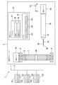
図1は、セラミック歯科補綴部品を製造するためのCAD/CAM機械加工ステーション2を備えるCAD/CAM機械加工システム1を示す。CAD/CAM機械加工システム1は、製造する歯科補綴部品のうちの1つ又は複数の最終寸法を指定するCADファイル4.1を生成するための少なくとも1つのCADデバイス3.1を備える。
Figure 1 shows a CAD/CAM machining system 1 with a CAD/
例えば、CADデバイス3.1は、患者から3D測定データを取得するためのスキャナを含む。代替として、3D測定データは、歯科医からデジタル形式で受信することができる。CADデバイス3.1は、製造する歯科補綴部品を指定するCADファイル4.1を生成するべくCADソフトウェアを実行するために用いられる。Dentsply SironaからのinEos X5などの適切なスキャナが市販されている。 For example, the CAD device 3.1 includes a scanner for acquiring 3D measurement data from a patient. Alternatively, the 3D measurement data can be received in digital form from a dentist. The CAD device 3.1 is used to run CAD software to generate a CAD file 4.1 that specifies the dental prosthetic part to be manufactured. Suitable scanners are commercially available, such as the inEos X5 from Dentsply Sirona.
CADファイル4.1は、インターネットなどの通信ネットワーク5を介して機械加工ステーション2に送信することができる。本質的に同じ設計を有するさらなるCADデバイス3.2、3.3などが、さらなる歯科補綴部品の最終寸法を指定するさらなるCADファイル4.2、4.3などを生成するべく、対応するCADファイルを、通信ネットワーク5を介して機械加工ステーション2に送信することができる。
The CAD file 4.1 can be transmitted to the
機械加工ステーション2は、ブランク7を機械加工ステーション2内に取り付けるためのマウント装置6を備える。例えば、マウント装置6は、ブランク7の周縁をマウント装置6内にクランプするように設計される。マウント装置6は、ベアリング8、9によってY軸を中心として回転可能に保持される。Y軸を中心とした回転は、制御ユニット11で制御可能なマウント装置6の駆動ユニット10によってもたらされる。Y軸を中心としたマウント装置6の回転位置合わせに加えて、駆動ユニット10は、XY平面内で位置決めを行うように設計することができ、その目的のために、駆動ユニット10を制御ユニット11で適宜制御することができる。
The
機械加工ステーション2は、ここで説明する実施形態ではピン形状を有する研削ツール12を受け入れるためのスピンドルモータ16をさらに備える。スピンドルモータ16は、縦軸13を中心として研削ツール12を回転させるために用いられる。ここで説明する実施形態では、スピンドルモータ16は、さらなる駆動ユニット14によってマウント装置6に対して位置決めすることができ、その目的のために、駆動ユニット14を制御ユニット11で制御することができる。例えば、スピンドルモータ16は、駆動ユニット14で3つのすべての空間方向X、Y、及びZに位置決めすることができる。
The
機械加工ステーション2の制御ユニット11は、CADデバイス3.1、3.2、3.3などから受信したCADファイル4.1、4.2、4.3などを格納するための少なくとも1つの電子メモリ15を備える。
The
制御ユニット11は、例えばプログラムコンポーネント18及び19を含むコンピュータプログラムを実行するための少なくとも1つのマイクロプロセッサ17をさらに備える。
The
プログラムコンポーネント18は、CADファイル4.1、4.2、4.3などから軌道を計算するために用いられ、この軌道に沿って、研削ツール12は、指定された歯科補綴部品を製造するためにブランク7を機械加工する必要がある。
The
プログラムコンポーネント19は、プログラムコンポーネント18によって計算された軌道に従ってブランク7を機械加工するために、駆動ユニット10及び14の、そしてまたスピンドルモータ16の、制御コマンドを生成する。
ここで説明する実施形態では、ブランク7は通り穴20を有し、これは研削ツール12を、ブランク7と接触せずに、通り穴20に軸方向に、ここではZ軸に沿って、完全に導入できるように設計される。例えば、通り穴20は、研削ツール12の直径より大直径の、円柱形の形状を有する。他の幾何学的形状も可能である。
In the embodiment described here, the blank 7 has a through
例えば、通り穴20は、研削ツールが通り穴に導入されるときに研磨研削作用が生じるように、研削ツール12を受け入れるほどには十分な大きさではない形状を有することができる。
For example, the through
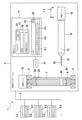
図2は、コンピュータプログラムによって軌道及び制御コマンドが計算された後の及び研削ツール12がブランク7に送られた後のCAD/CAM機械加工システム1を示し、ここでは、ブランク7と研削ツール12は、駆動ユニット10及び/又は14によって、研削ツール12が通り穴12に接触せずに完全に導入された状態に、相対的な位置が変化している。縦軸13を中心として研削ツール12を回転させるためにスピンドルモータ16が既にオンに切り換えられているかどうかは無関係である。
Figure 2 shows the CAD/CAM machining system 1 after the trajectory and control commands have been calculated by the computer program and after the grinding
図3は、図2に示されているブランク7と研削ツール12の相対的な位置から開始して、より具体的にはブランク7と研削ツール12との最初の接触を確立するために駆動ユニット10及び/又は14の制御によって別の相対的な移動が行われた後のCAD/CAM機械加工システム1を示す。この目的のために、研削ツール12は、研削ツールが通り穴20と接触面21で接触するまで、通り穴20の軸方向の縁23に垂直なy方向に移動される。次いで、研削ツール12は、スピンドルモータ16によって縦軸13を中心として回転させられる。研削ツール12は、特定の粒径を有するダイヤモンドなどの研磨要素を含む側面22を有し、それにより、接触面21で材料が除去される。研削ツール12の端面26には負荷がかからない。
Figure 3 shows the CAD/CAM machining system 1 after another relative movement has been made under the control of the
したがって、ここでのブランク7と研削ツール12の最初の接触は、例えば軸方向にすなわちZ方向に延びる通り穴12の縁23に対して、研削ツール12の側面22が垂直にすなわちy方向に移動することで起こり、したがって、この最初の接触が確立されるときに側面22がZ方向の厚さの全体にわたって縁23と接触し、これにより接触面21が生じる。
The initial contact between the blank 7 and the grinding
縦軸13を中心とした側面22の回転により、接触面全体に沿って研削ツール12の研磨要素の相対運動が生じ、それにより、接触面21全体に沿って本質的に同じ相対速度でブランク7から材料が除去される。
Rotation of the
次いで、この最初の接触から進んで、制御ユニット11は、CADファイル4.1、4.2、4.3などで指定された歯科補綴部品がブランク7から機械加工されるように、制御コマンドによって駆動ユニット10及び/又は14を制御する。これは、研削による機械加工により、特に高い精度で、特に高い表面品質で、ツール交換又はその後の焼結の必要なしに行われるという点で、ここでは特に有利である。このようにして製造された歯科補綴部品は、さらなる処理ステップなしに、歯科医が患者に直接使用することができる。
Proceeding from this first contact, the
図4Aは、マウント装置6が凹部24を備える、CAD/CAM機械加工システム1の一実施形態を示す。これらの凹部24は、図1、図2、及び図3と同様に、研削ツール12がブランク7の縁25にアクセスすることを可能にする。したがって、ここで説明する実施形態では存在する必要がないブランク7の通り穴20に導入される代わりに、研削ツール12は、マウント装置6の凹部24のうちの1つに導入され、次いで、側面22がブランク7の縁25に対して移動され、そこで接触面21と同様に接触面を形成する。
Figure 4A shows an embodiment of the CAD/CAM machining system 1 in which the mounting
この実施形態は、通り穴20のない標準的なブランクを使用することができるという利点を有する。
This embodiment has the advantage that a standard blank without through
図4Bは、例えば図1、図2、及び図3に係る実施形態で使用され得る、凹部24のない環状のマウント装置6の幾何学的形状を示す。
Figure 4B shows the geometry of an
図4Cは、マウント装置の周縁に均等に分布し、それぞれマウント装置6にクランプされるブランク7の縁25への半径方向のアクセスを提供する複数の凹部24を有するマウント装置6の幾何学的形状を示す。
Figure 4C shows the geometry of the mounting
図4Dは、4つの凹部24が、均等に配置されていないが曲線形状を有する、図4Cに係るマウント装置6の代替的な実施形態を示す。
Figure 4D shows an alternative embodiment of the mounting
マウント装置6の代わりに、ブランク7のアダプタ又はケーシングが、図4A、図4B、図4C、又は図4Dに係る幾何学的形状を有することもできる。
Instead of the mounting
図5A及び図5Bは、ブランクと側面22との最初の接触の利点を再び示している。図5Aに示すように、最初の接触が研削ツール12の側面22ではなく端面26で確立される場合、研削ツール12とブランク7との接触点での縦軸13を中心とした回転中心で相対運動は起こらず、したがって、研削ツール12でブランク7から材料をほとんど除去することができないか又は摩耗が多いだけである。
5A and 5B again show the advantage of initial contact between the blank and the
対照的に、最初の接触が、図1~図4に係る実施形態と同様にブランク7と研削ツール12の側面22とで起こる場合、研磨要素がブランク7に対して相対運動する接触面21が形成され、それにより、高い表面品質及び高い精度でツールに優しい材料除去が可能となる。
In contrast, when the initial contact occurs between the blank 7 and the
図6は、2つの凹部24.1及び24.2を有するブランク7の一実施形態のためのCAD/CAM機械加工システム1のさらなる実施形態を示す。 Figure 6 shows a further embodiment of a CAD/CAM machining system 1 for one embodiment of a blank 7 having two recesses 24.1 and 24.2.
凹部24.1及び24.2は、それぞれ止り穴として設計することができる。これらの止り穴の深さは、合計すると少なくともブランク7の厚さとなる。このようにして、以下のような機械加工が可能となる:
1.最初に、研削ツール12を凹部24.1に導入し、次いで、凹部24.1の縁で最初の接触面21.1を形成する。
2.凹部24.2に向かう方向に、ここではY方向に研削ツール12を移動させることにより、図6に示す階段状の幾何学的形状の通り穴20が作製される。
3.凹部24.1及び24.2がこのようにつながれば、作製された通り穴20に研削ツール12を導入することができ、図1、図2、図3に係る実施形態と同様にさらなる機械加工を行うことができる。
The recesses 24.1 and 24.2 can each be designed as blind holes, the depth of which amounts in total to at least the thickness of the blank 7. In this way, the following machining is possible:
1. First, the grinding
2. By moving the grinding
3. Once the recesses 24.1 and 24.2 are thus connected, a grinding
図7は、マウント装置6内に配置されたブランク7の上面図である。ブランク7は、例えばブランク7にプレス加工することによってブランク7の製造中に形成される通り穴20を有することができる。代替として、ブランク7は、通り穴20なしで製造することもできる。その場合、通り穴20は、ブランク7が製造された後に、ミリング、特にドリリングによって、後であけられる。
Figure 7 is a top view of the blank 7 arranged in the mounting
通り穴20の代替として、上部が開口しているキャビティ、すなわち凹部24.1及び24.2を、ブランク7の両方の側部に形成又はミリングすることができる(図6参照)。
As an alternative to the through
図8は、マウント装置6内のブランク7のさらなる実施形態を示し、ブランク7はその縁27上に凹部28を有し、これはブランク7とマウント装置8の間に空間を形成する。この実施形態では、この空間を介してブランク7の縁27に軸方向にアクセスすることができ、この空間を介して研削ツール12を最初の接触のためにブランク7に移動させることができる。
Figure 8 shows a further embodiment of the blank 7 in the mounting
図9は、偏心通り穴20を有するブランク7を含むCAD-CAM機械加工システム1のさらなる実施形態を示す。マウント装置6に対する通り穴20の位置を定義するためにブランク7上又は内にマーキング29を設けることができ、対応するマーキング30をマウント装置6上又は内に設けることができる。ブランク7をマウント装置6にクランプするときに、ユーザは、マーキング29及び30を互いに位置合わせし、したがって、通り穴は、制御ユニット11による移動に用いることができる所定の位置Pをとることになる。
Figure 9 shows a further embodiment of the CAD-CAM machining system 1 including a blank 7 with an eccentric through
代替として又は加えて、制御ユニット11は、マウント装置6に対する通り穴20の位置Pを自動的に検出することができる。この目的のために、機械加工ステーション2は、通り穴20の位置Pを検出する光学センサなどのセンサ31を備える。その場合、この位置Pを示す適切なデータ32はメモリ15に記憶される。マイクロプロセッサ17は、プログラムコンポーネント33を実行して、位置Pを確認することができ、データ32を格納することができる。次いで、プログラムコンポーネント18及び/又は19が、軌道の開始点を指定するこの位置Pを考慮に入れて、軌道を計算し、制御コマンドを生成する。代替として又は加えて、センサがマーキング29の位置を、したがって、間接的に通り穴の位置も、確かめることができる。
Alternatively or additionally, the
図10は、図9に係る実施形態のブランク7の上面図である。 Figure 10 is a top view of the blank 7 of the embodiment shown in Figure 9.
さらなる実施形態によれば、通り穴20は、円筒形円盤形ブランク7の中心を通って軸方向に延びることもでき、したがって、この場合、マーキング29、30を省くことができる。これは図10に点線で示されている。
According to a further embodiment, the through
さらなる実施形態によれば、ブランク7の縁とマウント装置6との機械的インターフェースは、事前定義された位置でのみブランク7をマウント装置6にクランプできるように設計することができる。この目的のために、例えば、回転をロックするための、すなわち回転を防止するためのガイド溝をマウント装置6に設けることができる。
According to a further embodiment, the mechanical interface between the edge of the blank 7 and the mounting
図11は、円筒形の研削ツール12の代わりに円錐部34を有する研削ツール12が用いられる本発明の別の実施形態を示す。この実施形態では、円錐形の形状に基づいて同じく図11に示されている所望の接触面が生じるため、通り穴20などの凹部は不要である。
Figure 11 shows another embodiment of the invention in which a grinding
この目的のために、ブランク7と研削ツール12の円錐面34は、ブランク7の表面上で円錐面34との最初の接触がなされてそこに接触面21が生じるような角度設定で、制御ユニット11によって相対的な位置が決定される。角度設定は、研削ツールの回転中心に対して行われる。したがって、ブランク7と研削ツール12のz方向の相対的な送りによって、ブランク7を貫通する通り穴20をあけることができ、そこから進んで、軌道に沿ってさらなる機械加工が行われる。z方向の送りに加えて、随意的に、好ましくはそれぞれz方向の送りよりも小さい、x方向及び/又はy方向の送り成分が存在してもよい。
For this purpose, the blank 7 and the
さらなる実施形態によれば、円錐形の研削ツールの代わりに円錐台を有する研削ツールが使用され、最初の接触面21は、円錐台の上面とではなく側面と形成され、したがって、研磨粒子の相対運動が同様に接触面全体で生じる。
According to a further embodiment, instead of a conical grinding tool, a grinding tool with a truncated cone is used, in which the
図12~図17は、球形の作業面を有する研削ツール12が使用されるさらなる実施形態を示す。図12~図17は、ブランク7内の通り穴20の作製を示す。
Figures 12-17 show a further embodiment in which a grinding
ここでは、最初の接触は、研削ツールがブランク7の表面に直角にではなくブランク7の表面法線に対して傾斜して配置されることで確立される。これにより、接触面21の各点と研削ツール12の球形の作業面上の研磨粒子との相対運動が確実に生じる。
Here, initial contact is established by positioning the grinding tool at an angle to the surface normal of the blank 7, rather than perpendicular to the surface of the blank 7. This ensures relative movement between each point of the
次いで、図12~図17に示すように、研削ツール12は、作製される通り穴の輪郭内で揺れ動くように前後に移動され、研削ツール12は、この前後の移動中にブランクに対して垂直になる位置に到達すると上昇する。研削ツール12が前述の位置に上昇することにより、その回転中心では相対運動は存在しない接触面が束の間に形成されることが回避される。そのような接触面の形成は、駆動ユニット10及び/又は14の適切な制御により制御ユニット11が研削ツール12を前後の移動中に僅かに上昇させることで回避される。
The grinding
実施形態は、特許請求される主題と任意の組み合わせで組み合わせることができる以下の特徴の組み合わせのうちの1つ又は複数を含み得る:
A.CAD/CAM機械加工ステーション(2)によってセラミック歯科補綴部品を製造するための方法であって、
円盤形のセラミックブランク(7)を提供するステップと、
ブランクをCAD/CAM機械加工ステーションのマウント装置(6)内にブランクの周縁が囲まれるように取り付けるステップと、
研削ツールの縦軸(13)を中心とした回転により研削ツールとブランクの接触面(21)全体で相対運動が生じるようにブランクと研削ツールとの最初の接触を確立するべく、CAD/CAM機械加工ステーションを制御するステップと、
セラミック歯科補綴部品を製造するべく、最初の接触から進んで回転研削ツールによりブランクを機械加工するステップと、
を含む、方法。
Implementations may include one or more of the following feature combinations, which may be combined in any combination with the claimed subject matter:
A. A method for manufacturing a ceramic dental prosthetic part by means of a CAD/CAM machining station (2), comprising:
Providing a disc-shaped ceramic blank (7);
Mounting the blank in a mounting device (6) of a CAD/CAM machining station so that the blank is surrounded by its peripheral edge;
controlling the CAD/CAM machining station to establish initial contact between the blank and the grinding tool such that rotation of the grinding tool about its longitudinal axis (13) results in relative motion across the grinding tool/blank contact surface (21);
- machining the blank with a rotating grinding tool proceeding from the initial contact to produce a ceramic dental prosthesis part;
A method comprising:
B.ブランクが円形であることを特徴とする、項Aに記載の方法。 B. The method according to claim A, wherein the blank is circular.
C.凹部が、ブランクの製造中にプレス加工によってブランクに形成される、項A又は項Bに記載の方法。 C. The method of claim A or B, in which the recess is formed in the blank by pressing during manufacture of the blank.
D.凹部が、ブランクの前処理ステップ中に切削技術によって機械加工される、項A、項B、又は項Cに記載の方法。 D. The method of claim A, B, or C, wherein the recess is machined by cutting techniques during a preparation step of the blank.
E.凹部を空間的に配置できるように円盤形ブランクにマーキング(29)が設けられる、前記項のいずれかに記載の方法。 E. The method of any of the preceding paragraphs, in which the disk-shaped blank is provided with markings (29) so that the recesses can be spatially located.
F.ブランクが、長石、特に二ケイ酸リチウムガラスセラミックでできている長石様のガラスセラミック、特に酸化アルミニウム及び/又は酸化ジルコニウムでできている結晶セラミックである、前記項のいずれかに記載の方法。 F. The method according to any of the preceding paragraphs, wherein the blank is a feldspar-like glass ceramic made of feldspar, in particular a lithium disilicate glass ceramic, in particular a crystalline ceramic made of aluminum oxide and/or zirconium oxide.
G.ブランクが、十分に焼結された、特にヒップされたセラミックで作製される、前記項のいずれかに記載の方法。 G. The method according to any of the preceding paragraphs, in which the blank is made of fully sintered, in particular hipped, ceramic.
H.最終強度の歯科用セラミックで作製された円盤形ブランクであって、最終強度の歯科用セラミックの周囲を囲むケーシングを備え、ケーシングが最終強度のセラミックよりも軟質の材料で作製される、特に木材又はプラスチック材料で作製される、円盤形ブランク。 H. A disc-shaped blank made of a final strength dental ceramic, with a casing surrounding the final strength dental ceramic, the casing being made of a material softer than the final strength ceramic, in particular a wood or plastic material.
I.ブランクの厚さ全体を通して延びる少なくとも1つの凹部(24、28)を備える、最終強度の歯科用セラミックで作製された円盤形ブランク。 I. A disk-shaped blank made of final strength dental ceramic with at least one recess (24, 28) extending through the entire thickness of the blank.
J.凹部(28)がブランクの縁に配置される、項Iに記載の円盤形ブランク。 J. A disk-shaped blank as described in paragraph I, in which the recesses (28) are disposed on the edges of the blank.
K.凹部が、ブランクを貫通する通り穴(20)である、項Jに記載の円盤形ブランク。 K. A disk-shaped blank as described in paragraph J, in which the recess is a through hole (20) that passes through the blank.
L.最終強度の歯科用セラミックで作製された円盤形ブランクであって、最終強度の歯科用セラミックのそれぞれの凹部(24.1、24.2)がブランクの両方の側部に配置され、凹部の深さが合計すると少なくともブランクの厚さになる、円盤形ブランク。 L. A disk-shaped blank made of final strength dental ceramic, in which respective recesses (24.1, 24.2) of the final strength dental ceramic are located on both sides of the blank, the depths of the recesses totaling at least the thickness of the blank.
M.ブランクの回転位置決めのためのマーキングを備える、項H~項Lのいずれか一項に記載の円盤形ブランク。 M. A disk-shaped blank according to any one of claims H to L, having markings for rotational positioning of the blank.
1 CAD/CAM機械加工システム
2 CAD/CAM機械加工ステーション
3.1 CADデバイス
3.2 CADデバイス
3.3 CADデバイス
4.1 CADファイル
4.2 CADファイル
4.3 CADファイル
5 通信ネットワーク
6 マウント装置
7 ブランク
8 ベアリング
9 ベアリング
10 駆動ユニット
11 制御ユニット
12 研削ツール
13 縦軸
14 駆動ユニット
15 メモリ
16 スピンドルモータ
17 マイクロプロセッサ
18 プログラムコンポーネント
19 プログラムコンポーネント
20 通り穴
21 接触面
22 側面
23 縁
24 凹部
25 縁
26 端面
24.1 凹部
24.2 凹部
27 縁
28 凹部
29 マーキング
30 マーキング
31 センサ
32 データ
33 プログラムコンポーネント
34 円錐面
1 CAD/
Claims (12)
円盤形のセラミックブランク(7)を提供するステップと、Providing a disc-shaped ceramic blank (7);
前記ブランクを前記CAD/CAM機械加工ステーションのマウント装置(6)内に前記ブランクの周縁が囲まれるように取り付けるステップと、mounting said blank in a mounting arrangement (6) of said CAD/CAM machining station so that the blank is surrounded by its periphery;
研削ツールの縦軸(13)を中心とした回転により前記研削ツールと前記ブランクの接触面(21)全体で前記研削ツールの縦軸(13)を中心とした回転による相対運動が生じるように前記ブランクと前記研削ツールとの最初の接触を確立するべく、前記CAD/CAM機械加工ステーションを制御するステップと、controlling the CAD/CAM machining station to establish initial contact between the blank and the grinding tool such that rotation about the grinding tool's longitudinal axis (13) results in relative motion across a contact surface (21) between the grinding tool and the blank in rotation about the grinding tool's longitudinal axis (13);
セラミック歯科補綴部品を製造するべく、前記最初の接触から進んで回転する前記研削ツールにより前記ブランクを機械加工するステップと、machining the blank with the grinding tool rotating proceeding from said first contact to produce a ceramic dental prosthesis part;
を含み、Including,
前記マウント装置が、前記ブランクの縁に向かって開口している少なくとも1つの第1の凹部を有し、前記ブランクの周縁の少なくとも一部に沿って前記ブランクをクランプし、前記研削ツールが、前記研削ツールを前記ブランクに送るべく前記第1の凹部に導入され、前記最初の接触のために前記第1の凹部の開口を通して前記ブランクに移動される、方法。The method of claim 1, wherein the mounting device has at least one first recess opening toward an edge of the blank and clamps the blank along at least a portion of a periphery of the blank, and the grinding tool is introduced into the first recess to deliver the grinding tool to the blank and moved into the blank through the opening of the first recess for the initial contact.
円盤形のセラミックブランク(7)を提供するステップと、Providing a disc-shaped ceramic blank (7);
前記ブランクを前記CAD/CAM機械加工ステーションのマウント装置(6)内に前記ブランクの周縁が囲まれるように取り付けるステップと、mounting said blank in a mounting arrangement (6) of said CAD/CAM machining station so that the blank is surrounded by its periphery;
研削ツールと前記ブランクの接触面(21)全体で前記研削ツールの縦軸(13)を中心とした回転による相対運動が生じるように前記ブランクと前記研削ツールとの最初の接触を確立させる、前記CAD/CAM機械加工ステーションを制御するステップと、controlling the CAD/CAM machining station to establish initial contact between the blank and the grinding tool such that relative motion occurs across a contact surface (21) between the grinding tool and the blank in rotation about a longitudinal axis (13) of the grinding tool;
セラミック歯科補綴部品を製造するべく、前記最初の接触から進んで回転する前記研削ツールにより前記ブランクを機械加工するステップと、machining the blank with the grinding tool rotating proceeding from said first contact to produce a ceramic dental prosthesis part;
を含み、Including,
前記ブランクが、前記ブランクの縁に向かって開口している少なくとも1つの凹部を有するアダプタによって前記マウント装置に取り付けられ、前記アダプタは、前記ブランクの周縁の少なくとも一部に沿って前記ブランクをクランプし、前記研削ツールが、前記研削ツールを前記ブランクに送るべく前記アダプタの前記凹部に導入され、前記最初の接触のために前記アダプタの前記凹部の開口を通して前記ブランクに移動される、方法。The blank is attached to the mounting device by an adapter having at least one recess opening toward an edge of the blank, the adapter clamping the blank along at least a portion of a periphery of the blank, and the grinding tool is introduced into the recess of the adapter to deliver the grinding tool to the blank and moved into the blank through the opening of the recess of the adapter for the initial contact.
Priority Applications (1)
| Application Number | Priority Date | Filing Date | Title |
|---|---|---|---|
| JP2024108292A JP2024133614A (en) | 2018-11-15 | 2024-07-04 | CAD/CAM machining station, CAD/CAM machining system, and computer program |
Applications Claiming Priority (2)
| Application Number | Priority Date | Filing Date | Title |
|---|---|---|---|
| EP18206460.0A EP3653168B1 (en) | 2018-11-15 | 2018-11-15 | Method for producing ceramic dental prosthesis parts, cad/cam machining station and computer program |
| PCT/US2019/061939 WO2020102794A1 (en) | 2018-11-15 | 2019-11-18 | Method for producing ceramic dental prosthesis parts, cad/cam machining station, computer program and blank made of final-strength dental ceramic |
Related Child Applications (1)
| Application Number | Title | Priority Date | Filing Date |
|---|---|---|---|
| JP2024108292A Division JP2024133614A (en) | 2018-11-15 | 2024-07-04 | CAD/CAM machining station, CAD/CAM machining system, and computer program |
Publications (2)
| Publication Number | Publication Date |
|---|---|
| JP2022536224A JP2022536224A (en) | 2022-08-15 |
| JP7592012B2 true JP7592012B2 (en) | 2024-11-29 |
Family
ID=64331751
Family Applications (2)
| Application Number | Title | Priority Date | Filing Date |
|---|---|---|---|
| JP2021526495A Active JP7592012B2 (en) | 2018-11-15 | 2019-11-18 | Method for manufacturing a ceramic dental prosthetic part - Patent application |
| JP2024108292A Pending JP2024133614A (en) | 2018-11-15 | 2024-07-04 | CAD/CAM machining station, CAD/CAM machining system, and computer program |
Family Applications After (1)
| Application Number | Title | Priority Date | Filing Date |
|---|---|---|---|
| JP2024108292A Pending JP2024133614A (en) | 2018-11-15 | 2024-07-04 | CAD/CAM machining station, CAD/CAM machining system, and computer program |
Country Status (8)
| Country | Link |
|---|---|
| US (2) | US20210393381A1 (en) |
| EP (3) | EP3900667B1 (en) |
| JP (2) | JP7592012B2 (en) |
| KR (1) | KR20220088627A (en) |
| CN (1) | CN113164238B (en) |
| AU (1) | AU2019379822B2 (en) |
| CA (1) | CA3117683A1 (en) |
| WO (1) | WO2020102794A1 (en) |
Citations (7)
| Publication number | Priority date | Publication date | Assignee | Title |
|---|---|---|---|---|
| JP2002320626A (en) | 2001-03-26 | 2002-11-05 | Kaltenbach & Voigt Gmbh & Co | Cutting and grinding machine for manufacturing dental care workpieces to be processed |
| JP2006521842A (en) | 2003-04-04 | 2006-09-28 | クサヴェクス・アクチエンゲゼルシャフト | Method for manufacturing a dental prosthesis |
| JP2010131395A (en) | 2008-12-05 | 2010-06-17 | Ivoclar Vivadent Ag | Addressable matrices/cluster blanks for dental cad/cam systems and optimization method thereof |
| DE102009011442A1 (en) | 2009-02-24 | 2010-09-23 | Wieland Dental + Technik Gmbh & Co. Kg | Dental prostheses i.e. tooth crowns, manufacturing method for patient, involves aligning dental prostheses such that reference directions point dental prostheses in direction of upper side and lower side of blank |
| WO2013117540A1 (en) | 2012-02-06 | 2013-08-15 | Wieland Dental + Technik Gmbh & Co. Kg | Blank holder for dental milling machine |
| US20140377718A1 (en) | 2012-02-13 | 2014-12-25 | 3M Innovative Properties Company | Dental milling block containing individualized dental article and process of production |
| JP2017047175A (en) | 2015-08-31 | 2017-03-09 | 株式会社松風 | Dental restoration manufacturing system manufacturing dental restoration from dental cutting object having open hole, operation method and program of the same, and dental cutting object used in the same |
Family Cites Families (30)
| Publication number | Priority date | Publication date | Assignee | Title |
|---|---|---|---|---|
| DE19801530C1 (en) * | 1998-01-16 | 1999-12-09 | Stefan Wolz | Method of producing entirely ceramic inlays, crowns, bridges, partial bridges and frames for dental implants or superstructures |
| EP1106146A1 (en) * | 1999-12-02 | 2001-06-13 | Eidgenössische Technische Hochschule Zürich | Machine tool for the production of preforms for dental prosthesis |
| US6832877B2 (en) * | 2000-05-29 | 2004-12-21 | Kabushiki Kaisya Advance | Dental measuring and machining system |
| WO2001097707A1 (en) * | 2000-06-22 | 2001-12-27 | 3M Espe Ag | Device for producing dental workpieces |
| AU2002223358B2 (en) * | 2000-12-07 | 2004-10-28 | Eidgenossische Technische Hochschule Zurich Nichtmetallische Werkstoffe | Holding device for a ceramic blank |
| DE10120341B4 (en) * | 2001-01-30 | 2005-07-14 | Sirona Dental Systems Gmbh | Method for determining current position data of a machining tool |
| EP1658825B1 (en) * | 2004-11-22 | 2016-12-21 | 3M Deutschland GmbH | System and method for manufacturing dental prostheses |
| DE102004063417B4 (en) * | 2004-12-23 | 2006-08-24 | Sirona Dental Systems Gmbh | Blank for the production of dental moldings and method for producing the molded part |
| DE102005039010B4 (en) * | 2005-08-16 | 2008-04-30 | Sirona Dental Systems Gmbh | Machining device with measuring device for a model |
| DE102006023673B4 (en) * | 2006-05-19 | 2013-07-04 | Institut Straumann Ag | Milling device for producing dental prostheses |
| GB0702196D0 (en) * | 2007-02-06 | 2007-03-14 | 3M Innovative Properties Co | Device for producing a dental workpiece |
| US8551622B2 (en) | 2007-07-20 | 2013-10-08 | Ivoclar Vivadent Ag | Addressable matrices/cluster blanks for dental CAD/CAM systems and optimization thereof |
| US8443502B2 (en) * | 2007-09-14 | 2013-05-21 | Ivoclar Vivadent Ag | Blank arrangement |
| US20090275000A1 (en) * | 2009-04-28 | 2009-11-05 | Yunoh Jung | System and Method for Securing Multiple Ceramic Dental Blocks for Milling |
| KR20120099696A (en) * | 2009-10-28 | 2012-09-11 | 쓰리엠 이노베이티브 프로퍼티즈 컴파니 | Dental implant mill blank articles and methods of making those |
| US8784021B2 (en) * | 2009-11-05 | 2014-07-22 | O'brien Dental Lab, Inc. | Jig device and apparatus and method of making a dental prosthesis or pattern therefor |
| US20110171604A1 (en) * | 2010-01-11 | 2011-07-14 | Duane Milford Durbin | Method for manufacturing and supply of dental prosthesis |
| CN103003041A (en) * | 2010-04-29 | 2013-03-27 | 牙科实验室铣床用品有限责任公司 | Methods, systems and apparatuses for producing products from blanks |
| DE102010016847A1 (en) * | 2010-05-07 | 2011-11-10 | Dentona Ag | Dental model blank |
| US9675433B2 (en) * | 2012-11-29 | 2017-06-13 | Jensen Industries Inc. | Adapter for dental milling blank |
| DE102014015423A1 (en) * | 2014-10-20 | 2016-04-21 | Amann Girrbach Ag | Milling machine and blank of a dental component |
| ES2822627T3 (en) * | 2014-10-22 | 2021-05-04 | Ivoclar Vivadent Ag | Dental machine tool |
| DE102015204174A1 (en) * | 2015-03-09 | 2016-09-15 | Precis Glashütte GmbH | Holding device for dental blanks |
| JP2017046794A (en) * | 2015-08-31 | 2017-03-09 | 株式会社ギコウ | Dental mill blank and manufacturing method of dental workpiece using the same as well as manufacturing program of dental workpiece |
| EP3178440A1 (en) * | 2015-12-10 | 2017-06-14 | Ivoclar Vivadent AG | Method for generating dental restorations and dental restoration generating device and milling body |
| JP6571511B2 (en) * | 2015-12-18 | 2019-09-04 | クラレノリタケデンタル株式会社 | Manufacturing method of dental mill blank and dental mill blank obtained by the manufacturing method |
| JP6431516B2 (en) * | 2016-12-07 | 2018-11-28 | ローランドディー.ジー.株式会社 | Workpiece holding device and cutting machine |
| EP3345723A1 (en) * | 2017-01-10 | 2018-07-11 | Ivoclar Vivadent AG | Method for controlling a machine tool |
| WO2018172180A1 (en) * | 2017-03-20 | 2018-09-27 | Straumann Holding Ag | System and method for manufacturing dental workpiece |
| EP3708114A1 (en) * | 2019-03-11 | 2020-09-16 | DeguDent GmbH | Blank for milling or grinding a dental article |
-
2018
- 2018-11-15 EP EP21171998.4A patent/EP3900667B1/en active Active
- 2018-11-15 EP EP21171965.3A patent/EP3912591B1/en active Active
- 2018-11-15 EP EP18206460.0A patent/EP3653168B1/en active Active
-
2019
- 2019-11-18 WO PCT/US2019/061939 patent/WO2020102794A1/en not_active Ceased
- 2019-11-18 CN CN201980081741.8A patent/CN113164238B/en active Active
- 2019-11-18 CA CA3117683A patent/CA3117683A1/en active Pending
- 2019-11-18 JP JP2021526495A patent/JP7592012B2/en active Active
- 2019-11-18 AU AU2019379822A patent/AU2019379822B2/en active Active
- 2019-11-18 US US17/291,844 patent/US20210393381A1/en not_active Abandoned
- 2019-11-18 KR KR1020217017013A patent/KR20220088627A/en not_active Ceased
-
2024
- 2024-07-04 JP JP2024108292A patent/JP2024133614A/en active Pending
-
2025
- 2025-04-14 US US19/178,155 patent/US20250235297A1/en active Pending
Patent Citations (7)
| Publication number | Priority date | Publication date | Assignee | Title |
|---|---|---|---|---|
| JP2002320626A (en) | 2001-03-26 | 2002-11-05 | Kaltenbach & Voigt Gmbh & Co | Cutting and grinding machine for manufacturing dental care workpieces to be processed |
| JP2006521842A (en) | 2003-04-04 | 2006-09-28 | クサヴェクス・アクチエンゲゼルシャフト | Method for manufacturing a dental prosthesis |
| JP2010131395A (en) | 2008-12-05 | 2010-06-17 | Ivoclar Vivadent Ag | Addressable matrices/cluster blanks for dental cad/cam systems and optimization method thereof |
| DE102009011442A1 (en) | 2009-02-24 | 2010-09-23 | Wieland Dental + Technik Gmbh & Co. Kg | Dental prostheses i.e. tooth crowns, manufacturing method for patient, involves aligning dental prostheses such that reference directions point dental prostheses in direction of upper side and lower side of blank |
| WO2013117540A1 (en) | 2012-02-06 | 2013-08-15 | Wieland Dental + Technik Gmbh & Co. Kg | Blank holder for dental milling machine |
| US20140377718A1 (en) | 2012-02-13 | 2014-12-25 | 3M Innovative Properties Company | Dental milling block containing individualized dental article and process of production |
| JP2017047175A (en) | 2015-08-31 | 2017-03-09 | 株式会社松風 | Dental restoration manufacturing system manufacturing dental restoration from dental cutting object having open hole, operation method and program of the same, and dental cutting object used in the same |
Also Published As
| Publication number | Publication date |
|---|---|
| EP3653168A1 (en) | 2020-05-20 |
| WO2020102794A1 (en) | 2020-05-22 |
| CN113164238A (en) | 2021-07-23 |
| US20210393381A1 (en) | 2021-12-23 |
| AU2019379822A1 (en) | 2021-06-24 |
| EP3653168B1 (en) | 2021-05-05 |
| JP2022536224A (en) | 2022-08-15 |
| EP3912591B1 (en) | 2023-03-15 |
| CN113164238B (en) | 2022-11-25 |
| BR112021009277A2 (en) | 2021-08-10 |
| EP3900667A1 (en) | 2021-10-27 |
| AU2019379822B2 (en) | 2024-11-07 |
| JP2024133614A (en) | 2024-10-02 |
| EP3900667B1 (en) | 2023-01-25 |
| EP3912591A1 (en) | 2021-11-24 |
| CA3117683A1 (en) | 2020-05-22 |
| WO2020102794A8 (en) | 2025-10-02 |
| US20250235297A1 (en) | 2025-07-24 |
| KR20220088627A (en) | 2022-06-28 |
Similar Documents
| Publication | Publication Date | Title |
|---|---|---|
| DK2844183T3 (en) | MILLING PROCEDURE FOR THE MANUFACTURING OF DENTAL PROTESTS | |
| US20120148985A1 (en) | Method for Machining a Dental Prosthesis | |
| JP2002320626A (en) | Cutting and grinding machine for manufacturing dental care workpieces to be processed | |
| JP7592012B2 (en) | Method for manufacturing a ceramic dental prosthetic part - Patent application | |
| JP7514829B2 (en) | Method for manufacturing ceramic dental prosthetic parts, CAD/CAM machining station, computer program, and blanks made of final strength dental ceramic | |
| JP2001001229A (en) | Working method for replica | |
| WO2002076328A1 (en) | An apparatus and a method for producing a dental restoration | |
| CN113784685B (en) | Method for manufacturing tooth replacement parts | |
| BR112021009277B1 (en) | METHOD FOR PRODUCING CERAMIC DENTAL PROSTHESIS PARTS, CAD/CAM MACHINING STATION AND SYSTEM, AND COMPUTER READABLE STORAGE MEDIA | |
| BR112021009267B1 (en) | RAW PART, METHOD FOR PRODUCING CERAMIC DENTAL PROSTHESIS PARTS, AND, CAD/CAM MACHINING STATION | |
| EP4331528A1 (en) | Cutting machining device, holding device, and machining method | |
| JP2012130698A (en) | Method and apparatus for manufacturing extraoral dental prosthesis | |
| WO2023282173A1 (en) | Dental end mill and processing method | |
| JP2000287997A (en) | Block for dental prosthesis | |
| US20100143867A1 (en) | method for producing a dental restoration | |
| WO2005058184A1 (en) | A method for producing a dental restoration |
Legal Events
| Date | Code | Title | Description |
|---|---|---|---|
| A621 | Written request for application examination |
Free format text: JAPANESE INTERMEDIATE CODE: A621 Effective date: 20221115 |
|
| A131 | Notification of reasons for refusal |
Free format text: JAPANESE INTERMEDIATE CODE: A131 Effective date: 20230822 |
|
| A521 | Request for written amendment filed |
Free format text: JAPANESE INTERMEDIATE CODE: A523 Effective date: 20231122 |
|
| A02 | Decision of refusal |
Free format text: JAPANESE INTERMEDIATE CODE: A02 Effective date: 20240305 |
|
| A521 | Request for written amendment filed |
Free format text: JAPANESE INTERMEDIATE CODE: A523 Effective date: 20240704 |
|
| A911 | Transfer to examiner for re-examination before appeal (zenchi) |
Free format text: JAPANESE INTERMEDIATE CODE: A911 Effective date: 20240731 |
|
| TRDD | Decision of grant or rejection written | ||
| A01 | Written decision to grant a patent or to grant a registration (utility model) |
Free format text: JAPANESE INTERMEDIATE CODE: A01 Effective date: 20241022 |
|
| A61 | First payment of annual fees (during grant procedure) |
Free format text: JAPANESE INTERMEDIATE CODE: A61 Effective date: 20241119 |
|
| R150 | Certificate of patent or registration of utility model |
Ref document number: 7592012 Country of ref document: JP Free format text: JAPANESE INTERMEDIATE CODE: R150 |