JP7591908B2 - Coordinate conversion system, coordinate conversion method and program - Google Patents
Coordinate conversion system, coordinate conversion method and program Download PDFInfo
- Publication number
- JP7591908B2 JP7591908B2 JP2020192745A JP2020192745A JP7591908B2 JP 7591908 B2 JP7591908 B2 JP 7591908B2 JP 2020192745 A JP2020192745 A JP 2020192745A JP 2020192745 A JP2020192745 A JP 2020192745A JP 7591908 B2 JP7591908 B2 JP 7591908B2
- Authority
- JP
- Japan
- Prior art keywords
- coordinate
- trajectory
- movement trajectory
- movement
- transformation
- Prior art date
- Legal status (The legal status is an assumption and is not a legal conclusion. Google has not performed a legal analysis and makes no representation as to the accuracy of the status listed.)
- Active
Links
Images


Landscapes
- Image Analysis (AREA)
- Navigation (AREA)
Description
本発明は、座標変換システム、座標変換方法及びプログラム関する。 The present invention relates to a coordinate transformation system, a coordinate transformation method, and a program.
移動する移動体の位置を推定する方法としては、GPS(Global Positioning System)を用いる方法と、撮像装置により撮像した動画像を用いる方法とがある。
GPSを用いる方法は、直接的に所定の周期における位置を検出して、検出結果として得た時系列の移動の軌跡を、絶対な座標(例えば、緯度軽度)を示す第1座標系、絶対座標系である第1座標系における第1移動軌跡として生成する(例えば、特許文献1)。
また、動画像を用いる方法は、例えばSLAM(Simultaneous Localization and Mapping)のように、動画像における画像間の被写体の大きさ変化や位置変化により、所定の周期毎の相対的な移動位置を示し、この移動位置を連結して得られる移動の軌跡を、相対的な位置変化を示す座標系である第2座標系における第1移動軌跡(相対的な変化位置に対応した移動軌跡)を生成する(例えば、特許文献2)。
Methods for estimating the position of a moving object include a method using a global positioning system (GPS) and a method using a moving image captured by an imaging device.
A method using GPS directly detects a position at a specified period, and generates a time-series movement trajectory obtained as a result of the detection as a first coordinate system indicating absolute coordinates (e.g., latitude and longitude), a first movement trajectory in the first coordinate system which is an absolute coordinate system (e.g., Patent Document 1).
In addition, a method using moving images, such as SLAM (Simultaneous Localization and Mapping), indicates the relative movement position at a predetermined period based on changes in size and position of the subject between images in the moving image, and generates a first movement trajectory (a movement trajectory corresponding to the relative change position) in a second coordinate system, which is a coordinate system that indicates relative position changes, from the movement trajectory obtained by linking these movement positions (for example, Patent Document 2).
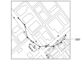
しかし、GPSで得られる位置座標は、実際の移動体の位置に対して数メートル程度の誤差があるため、図10に示すように、移動軌跡300T(以下、第1移動軌跡)における位置座標に誤差がノイズとして重畳するため、正確な移動軌跡が得られない問題がある。
また、SLAMで求められる移動軌跡400T(以下、第2移動軌跡)は、図11で示すように、GPSで得られた移動軌跡300Tとは異なり、ノイズは少ない形状として求められるが、独自の座標系(以下、ローカル座標系)における相対的な位置変化を示す情報として示されているため、実際の距離に対応した移動軌跡を得ることができない。
However, since the position coordinates obtained by GPS have an error of about several meters from the actual position of the moving body, as shown in Figure 10, the error is superimposed as noise on the position coordinates in the
Furthermore, as shown in FIG. 11, the
そのため、従来においては、第2座標系における第2移動軌跡を、第1座標系(世界座標系)における第1移動軌跡に対応させて、第1座標系(世界座標系)に対して線形的な座標変換(線形変換行列による線形座標変換、以下、単に座標変換と示す場合もある)を行うことで、最終的に移動体の移動軌跡としている。
ここで、座標変換を行うための上記線形変換行列は、例えば、Umeyama法(例えば、非特許文献1参照)が用いられている。
これにより、図12に示すように、図10のGPSによる移動軌跡に比較し、実際の移動軌跡に対応した滑らかな形状の移動軌跡400T’を得ることができる。
Therefore, conventionally, the second movement trajectory in the second coordinate system is matched to the first movement trajectory in the first coordinate system (world coordinate system), and a linear coordinate transformation (linear coordinate transformation using a linear transformation matrix, hereinafter sometimes simply referred to as coordinate transformation) is performed on the first coordinate system (world coordinate system) to ultimately obtain the movement trajectory of the moving body.
Here, for example, the Umeyama method (see, for example, Non-Patent Document 1) is used as the linear transformation matrix for performing the coordinate transformation.
As a result, as shown in FIG. 12, a
上述したように、従来の方法においては、図10のGPSで求めた第1移動軌跡(300T)に合わせて、SLAMで用いた図11の第2移動軌跡(400T)の線形変換(例えば上記Umeyama法)を行った場合、GPSの場合のようにノイズの影響は無くなる。
しかしながら、SLAMで生成した第2移動軌跡には、軌跡の周囲のスケールが徐々に大きくなる、あるいは小さくなるスケールドリフトの影響が反映される。
このため、図13に示すように、実際の軌跡(移動軌跡501T)に対して、SLAMのスケールドリフトの影響により、線形変換結果の第2移動軌跡(400T’)における移動における距離間隔が実際と異なってしまう。
As described above, in the conventional method, when a linear transformation (for example, the above-mentioned Umeyama method) is performed on the second movement trajectory (400T) in FIG. 11 used in SLAM to match it with the first movement trajectory (300T) obtained by GPS in FIG. 10, the influence of noise as in the case of GPS is eliminated.
However, the second movement trajectory generated by SLAM reflects the effect of scale drift, in which the scale around the trajectory gradually increases or decreases.
For this reason, as shown in FIG. 13, due to the effect of scale drift in SLAM, the distance interval in the movement of the second movement trajectory (400T') resulting from the linear transformation differs from the actual trajectory (
本発明は、このような状況に鑑みてなされたもので、GPSにより生成される、ノイズを含む移動位置からなる歪んだ第1移動軌跡から、従来例に比較してより実際に移動した軌跡に近い形状の推定移動軌跡を生成することができる座標変換システム、座標変換方法及びプログラムを提供する。 The present invention has been made in consideration of such circumstances, and provides a coordinate transformation system, coordinate transformation method, and program that can generate an estimated movement trajectory that is closer in shape to the actual movement trajectory than conventional examples from a distorted first movement trajectory that is generated by GPS and consists of movement positions that include noise.
本発明の座標変換システムは、GPS(Global Positioning System)により計測した移動体の時系列な移動位置の各々を用いて、実距離の第1座標系における第1移動軌跡を生成する第1移動軌跡生成部と、移動する風景を撮像した時系列な撮像画像の各々を用いて、前記移動体の相対的な位置の変化を示す第2座標系における第2移動軌跡を生成する第2移動軌跡生成部と、前記第2移動軌跡を所定の幅に分割して分割第2移動軌跡の各々を生成する第2移動軌跡分割部と、前記分割第2移動軌跡の各々を、第1座標系における前記第1移動軌跡の対応する部分に合わせて線形座標変換を行い、前記移動体の移動の軌跡を推定した推定移動軌跡を生成する座標変換部とを備えることを特徴とする。 The coordinate transformation system of the present invention is characterized by comprising a first movement trajectory generation unit that generates a first movement trajectory in a first coordinate system of actual distance using each of the time-series movement positions of a moving object measured by a GPS (Global Positioning System), a second movement trajectory generation unit that generates a second movement trajectory in a second coordinate system that indicates a change in the relative position of the moving object using each of the time-series captured images of a moving landscape, a second movement trajectory division unit that divides the second movement trajectory into a predetermined width to generate each of the divided second movement trajectories, and a coordinate transformation unit that performs linear coordinate transformation on each of the divided second movement trajectories to match the corresponding portion of the first movement trajectory in the first coordinate system, and generates an estimated movement trajectory that estimates the movement trajectory of the moving object.
本発明の座標変換システムは、前記分割第2移動軌跡の各々を、第1座標系における前記第1移動軌跡の部分に対応して座標変換する変換行列を補正する変換行列補正部をさらに備え、前記座標変換部が、前記分割第2移動軌跡の各々を、前記第2座標系から前記第1座標系における前記第1移動軌跡に対応して線形変換する前記変換行列を生成し、前記変換行列補正部が、隣接する分割第2移動軌跡の各々の前記変換行列における要素それぞれの変化量を低減する補正を行い、前記座標変換部が、前記変換行列補正部が補正した前記変換行列を用いて、前記分割第2移動軌跡の座標変換を行い、前記推定移動軌跡を生成することを特徴とする。 The coordinate transformation system of the present invention further includes a transformation matrix correction unit that corrects a transformation matrix that transforms each of the divided second movement trajectories into a coordinate corresponding to a portion of the first movement trajectory in a first coordinate system, the coordinate transformation unit generates the transformation matrix that linearly transforms each of the divided second movement trajectories from the second coordinate system into a coordinate corresponding to the first movement trajectory in the first coordinate system, the transformation matrix correction unit performs a correction to reduce the amount of change of each element in the transformation matrix of each of the adjacent divided second movement trajectories, and the coordinate transformation unit performs coordinate transformation of the divided second movement trajectories using the transformation matrix corrected by the transformation matrix correction unit to generate the estimated movement trajectory.
本発明の座標変換システムは、前記座標変換部が、隣接する分割第2移動軌跡の各々の前記変換行列における要素のそれぞれを、より変化量が低減された数値とする関数をガウス過程により求め、前記変換行列の前記要素を当該関数により算出することを特徴とする。 The coordinate transformation system of the present invention is characterized in that the coordinate transformation unit uses a Gaussian process to determine a function that reduces the amount of change in each of the elements in the transformation matrix of each of the adjacent divided second movement trajectories, and calculates the elements of the transformation matrix using the function.
本発明の座標変換システムは、前記座標変換部が、隣接する分割第2移動軌跡の各々の前記変換行列における要素を、連続する前記分割第2移動軌跡それぞれの当該変換行列の元々の要素を用いてカルマンフィルタにより推定した数値にとすることを特徴とする。 The coordinate transformation system of the present invention is characterized in that the coordinate transformation unit sets elements in the transformation matrix of each of the adjacent divided second movement trajectories to values estimated by a Kalman filter using the original elements of the transformation matrix of each of the consecutive divided second movement trajectories.
本発明の座標変換方法は、第1移動軌跡生成部が、GPS(Global Positioning System)により計測した移動体の時系列な移動位置の各々を用いて、実距離の第1座標系における第1移動軌跡を生成する第1移動軌跡生成過程と、第2移動軌跡生成部が、移動する風景を撮像した時系列な撮像画像の各々を用いて、前記移動体の相対的な位置の変化を示す第2座標系における第2移動軌跡を生成する第2移動軌跡生成過程と、第2移動軌跡分割部が、前記第2移動軌跡を所定の幅に分割して分割第2移動軌跡の各々を生成する第2移動軌跡分割過程と、座標変換部が、前記分割第2移動軌跡の各々を、第1座標系における前記第1移動軌跡の対応する部分に合わせて線形座標変換を行い、前記移動体の移動の軌跡を推定した推定移動軌跡を生成する座標変換過程とを含むことを特徴とする。 The coordinate transformation method of the present invention includes a first movement trajectory generation process in which a first movement trajectory generation unit generates a first movement trajectory in a first coordinate system of actual distance using each of the time-series movement positions of a moving object measured by a GPS (Global Positioning System); a second movement trajectory generation process in which a second movement trajectory generation unit generates a second movement trajectory in a second coordinate system indicating a change in the relative position of the moving object using each of the time-series captured images of a moving landscape; a second movement trajectory division process in which a second movement trajectory division unit divides the second movement trajectory into a predetermined width to generate each of the divided second movement trajectories; and a coordinate transformation process in which a coordinate transformation unit performs linear coordinate transformation on each of the divided second movement trajectories to match the corresponding portion of the first movement trajectory in the first coordinate system, and generates an estimated movement trajectory that estimates the movement trajectory of the moving object.
本発明のプログラムは、コンピュータを、GPS(Global Positioning System)により計測した移動体の時系列な移動位置の各々を用いて、実距離の第1座標系における第1移動軌跡を生成する第1移動軌跡生成手段、移動する風景を撮像した時系列な撮像画像の各々を用いて、前記移動体の相対的な位置の変化を示す第2座標系における第2移動軌跡を生成する第2移動軌跡生成手段、前記第2移動軌跡を所定の幅に分割して分割第2移動軌跡の各々を生成する第2移動軌跡分割手段、前記分割第2移動軌跡の各々を、第1座標系における前記第1移動軌跡の対応する部分に合わせて線形座標変換を行い、前記移動体の移動の軌跡を推定した推定移動軌跡を生成する座標変換手段として機能させるプログラムである。 The program of the present invention causes a computer to function as a first movement trajectory generating means for generating a first movement trajectory in a first coordinate system of actual distance using each of the time-series movement positions of a moving object measured by a GPS (Global Positioning System), a second movement trajectory generating means for generating a second movement trajectory in a second coordinate system indicating a change in the relative position of the moving object using each of the time-series captured images of a moving landscape, a second movement trajectory dividing means for dividing the second movement trajectory into a predetermined width and generating each of the divided second movement trajectories, and a coordinate conversion means for performing a linear coordinate conversion on each of the divided second movement trajectories to match the corresponding portion of the first movement trajectory in the first coordinate system and generating an estimated movement trajectory that estimates the movement trajectory of the moving object.
以上説明したように、本発明によれば、GPSにより生成される、ノイズを含む移動位置からなる歪んだ第1移動軌跡から、従来例に比較してより実際に移動した軌跡に近い形状の推定移動軌跡を生成することができる座標変換システム、座標変換方法及びプログラムを提供することが可能となる。 As described above, according to the present invention, it is possible to provide a coordinate transformation system, a coordinate transformation method, and a program that can generate an estimated movement trajectory that is closer in shape to the actual movement trajectory than conventional examples from a distorted first movement trajectory that is generated by GPS and consists of movement positions that include noise.
<第1の実施形態>
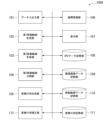
以下、本発明の第1の実施形態による座標変換システムの構成例について、図面を参照して説明する。図1は、本発明の第1の実施形態による座標変換システムの構成例を示すブロック図である。図1において、座標変換システム100は、データ入出力部101、第1移動軌跡生成部102、第2移動軌跡生成部103、第2移動軌跡分割部104、変換行列生成部105、座標変換部106、表示部107、GPSデータ記憶部108、撮像画像データ記憶部109、移動軌跡データ記憶部110及び変換行列記憶部111の各々を備えている。
First Embodiment
Hereinafter, a configuration example of a coordinate conversion system according to a first embodiment of the present invention will be described with reference to the drawings. Fig. 1 is a block diagram showing a configuration example of a coordinate conversion system according to a first embodiment of the present invention. In Fig. 1, a
データ入出力部101は、GPSにより取得された、GPS装置が搭載された移動体の移動に対応した時系列の位置データ(緯度経度における位置を示すデータであり、以降、GPSデータと示す)と、上記移動体に搭載された撮像装置により撮像された、移動体の周囲の風景を撮像した撮像画像のデータ(以降、撮像画像データと示す)との各々を、それぞれGPS装置(不図示)、撮像装置(不図示)それぞれから入力する。
また、データ入出力部101は、入力されるGPSデータをGPSデータ記憶部108に対して、ID(identification)番号(識別情報の一例)を付与して、当該ID番号とともに時系列に書き込んで記憶させる。
The data input/
Furthermore, the data input/
同様に、データ入出力部101は、入力される撮像画像データを撮像画像データ記憶部109に対して、ID番号を付与して、当該ID番号とともに時系列に書き込んで記憶させる。
ここで、GPS装置及び撮像装置の各々が、GPSデータ、撮像画像データそれぞれを取得するタイミングは、データ入出力部101により同期制御されている。
このため、GPSデータに付与されるID番号と撮像画像データに付与されるID番号とは、同一の番号である。
Similarly, the data input/
Here, the timing at which the GPS device and the imaging device acquire GPS data and captured image data, respectively, is synchronously controlled by the data input/
Therefore, the ID number assigned to the GPS data and the ID number assigned to the captured image data are the same number.
第1移動軌跡生成部102は、GPSデータをGPSデータ記憶部108から読出し、3次元座標系(例えば、緯度、経度及び高度の絶対座標系(第1座標系))に対して配置し、ID番号の順番に接続することにより、第1移動軌跡の曲線データを生成する。
そして、第1移動軌跡生成部102は、生成した第1移動軌跡の曲線データを移動軌跡データ記憶部110に対して書き込んで記憶させる。
図2は、第1移動軌跡生成部102が生成する第1移動軌跡の曲線データの一例を示す図である。図2において、ID番号に対応した、GPSデータの示す座標点201Pが、絶対座標系である緯度、経度及び高度からなる3次元座標系上に配置され、座標点201Pの各々が、ID番号の順番に線分201Lにより接続されている。
The first movement
Then, the first
Fig. 2 is a diagram showing an example of curve data of a first movement trajectory generated by the first movement
図1に戻り、第2移動軌跡生成部103は、撮像画像データを撮像画像データ記憶部108から読出し、ID番号の順番において撮像画像から前の位置からの相対的な位置変化量を求め(例えば、SLAMの手法を用いて求め)、3次元(例えば、x軸、y軸及びz軸、x軸及びy軸が地表面を形成する軸であり、z軸が高さ方向を示す軸)の相対座標系(第2座標系)に対して配置し、ID番号の順番に接続することにより、第2移動軌跡の曲線データを生成する。
そして、第2移動軌跡生成部103は、生成した第2移動軌跡の曲線データを、移動軌跡データ記憶部110に対して書き込んで記憶させる。
Returning to Figure 1, the second movement
Then, the second
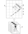
図3は、第2移動軌跡生成部103が生成する第2移動軌跡の曲線データの一例を示す図である。図3において、ID番号に対応した、撮像画像データ301から生成された移動位置を示す座標点302Pが、相対位置を示す相対座標系である3次元座標系(第2座標系)上に配置され、座標点302Pの各々が、ID番号の順番に線分302Lにより接続されている。
また、枠303、304及び305の各々は、第2移動軌跡を複数の移動位置単位(図3においては5個単位)で分割(分離)して分割第2移動軌跡(後述)を生成するための分割対象の移動位置を選択する枠である。
Fig. 3 is a diagram showing an example of curve data of a second movement trajectory generated by the second movement
Furthermore, each of
図1に戻り、第2移動軌跡分割部104は、第2移動軌跡生成部103が生成した第2移動軌跡を、複数の移動位置単位(図3における枠により選択される移動位置群)で分割することにより、上記分割第2移動軌跡を生成する。上記移動位置単位のグループにおける移動位置の個数は、ユーザが任意に設定することができる。ここで、グループにおける移動位置の個数を変化させ、最終的に生成される推定移動軌跡(後述)が実際の移動軌跡に最も近くなる移動位置の個数をシミュレーションにより、求めて、この個数をディフォルト値として用いる構成としてもよい。
Returning to FIG. 1, the second movement
変換行列生成部105は、分割第2移動軌跡に含まれるID番号の各々の座標点の座標値(以下、単に座標点として示す)が、第1移動軌跡における当該分割第2移動軌跡と同一のID番号の座標点それぞれに対応する位置に線形座標変換を行う線形変換行列(以下、単に変換行列と示す)を生成する。
このとき、変換行列生成部105は、分割第2移動軌跡における座標点と、第1移動軌跡における座標点とにおいて、同一のID番号の座標点間の距離、すなわち誤差(また、Umeyama法を用いた場合には誤差の二乗)の合計が最小となる位置に線形座標変換を行う変換行列を生成する。すなわち、この変換行列は、分割第2移動軌跡における座標点を第2座標系から、第1座標系の座標値に線形座標変換を行う行列である。
そして、変換行列生成部105は、生成した変換行列を変換行列記憶部111に対して書き込んで記憶させる。
The transformation
At this time, the transformation matrix generating
Then, the transformation
図4は、分割第2移動軌跡に含まれるID番号の各々の座標点と、当該分割第2移動軌跡に対応する変換行列との関係を示す図である。
変換行列M1は、ID番号がID1からID5までの座標値を含む分割第2移動軌跡(例えば、図3における枠303で分割された座標点から成る移動軌跡)を、当該ID番号がID1からID5の座標値の各々が、第1移動軌跡のID番号がID1からID5それぞれに対応して線形座標変換を行う変換行列である。
FIG. 4 is a diagram showing the relationship between the coordinate points of the ID numbers included in the divided second movement trajectories and the transformation matrix corresponding to the divided second movement trajectories.
The transformation matrix M1 is a transformation matrix that performs a linear coordinate transformation on a divided second movement trajectory (e.g., a movement trajectory consisting of coordinate points divided by
同様に、変換行列M2は、ID番号がID2からID6までの座標値を含む分割第2移動軌跡(例えば、図3における枠304で分割された座標点から成る移動軌跡)を、当該ID番号がID2からID6の座標値の各々が、第1移動軌跡のID番号がID2からID6それぞれに対応して線形座標変換を行う変換行列である。
他の、変換行列M3からM5の各々も、上述した変換行列M1及びM2の各々と同様である。
本実施形態においては、ID番号を一つずつ進行方向にシフトさせて、分割第2移動軌跡の各々を生成するため、それぞれの分割第2移動軌跡に含まれる移動位置は、当該分割第2移動軌跡の前後の分割第2移動軌跡と重複している。
Similarly, transformation matrix M2 is a transformation matrix that performs linear coordinate transformation on a divided second movement trajectory (e.g., a movement trajectory consisting of coordinate points divided by
Each of the other transformation matrices M3 to M5 is similar to each of the above-mentioned transformation matrices M1 and M2.
In this embodiment, each divided second movement trajectory is generated by shifting the ID number by one in the direction of travel, so that the movement positions included in each divided second movement trajectory overlap with the divided second movement trajectories before and after the divided second movement trajectory.
そして、座標変換部106は、第2移動軌跡における第2座標系における座標点を、第1移動軌跡に対応させて第1座標系における座標点に線形変換を行い、推定移動軌跡を生成する。
このとき、座標変換部106は、第2座標系における座標点の各々の線形座標変換に用いる変換行列の選択を行う。
例えば、座標変換部106は、第2座標系における座標変換対象の座標点が中央にある分割第2移動軌跡に対応した変換行列を変換行列記憶部111から読出し、当該変換行列を用いて座標点の第2座標系から第1座標系への線形座標変換を行う。図4を例とした場合、座標変換部106は、第2移動軌跡におけるID5の座標点を、第2座標系から第1座標系に線形座標変換を行う際に、変換行列M3を変換行列記憶部111から読出して使用する。
Then, the coordinate
At this time, the coordinate
For example, the coordinate
また、座標変換部106は、第2座標系における座標変換対象の座標点が含まれる分割第2移動軌跡に対応する変換行列の全てを変換行列記憶部111から読出し、変換行列における、同一の行及び列の位置の成分である要素のそれぞれの平均値を求めて、平均値を新たな要素とした平均変換行列を新たに生成し、座標変換対象の座標点の線形座標変換を行う構成としてもよい。
The coordinate
さらに、平均値を単に求めるだけでなく、対象の座標点が分割第2移動軌跡の何れの位置にあるかにより、それぞれの変換行列の要素の重み付けを持たせた(重み係数を付加した)加重平均により平均値を求める構成としてもよい。例えば、対象の座標点が中央にある分割第2移動軌跡に対応する行列の要素の重み係数を、対象の座標点が中央より外れた位置にある分割第2移動軌跡に対応する行列の要素の重み係数より大きく設定する。
図5に示す変換行列の場合、第2座標系におけるID番号がID5の座標点に対しては、変換行列M3の要素の重み係数を最も大きくし、変換行列M2及びM4の重み係数を変換行列M3の重み係数に比較してより小さく、変換行列M1及びM5の重み係数を変換行列M2及びM4の重み係数に比較してより小さく設定する。
Furthermore, instead of simply calculating the average value, the average value may be calculated by weighting the elements of each transformation matrix (by adding a weighting factor) depending on the position of the divided second movement trajectory of the target coordinate point. For example, the weighting factor of the matrix element corresponding to the divided second movement trajectory in which the target coordinate point is in the center is set to be larger than the weighting factor of the matrix element corresponding to the divided second movement trajectory in which the target coordinate point is in a position away from the center.
In the case of the transformation matrix shown in Figure 5, for a coordinate point with an ID number of ID5 in the second coordinate system, the weighting coefficient of the elements of transformation matrix M3 is set to the largest, the weighting coefficients of transformation matrices M2 and M4 are set to be smaller than the weighting coefficient of transformation matrix M3, and the weighting coefficients of transformation matrices M1 and M5 are set to be smaller than the weighting coefficients of transformation matrices M2 and M4.
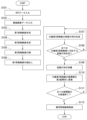
図5は、第1の実施形態における座標変換システムによる第2座標系における座標点を第1座標系に対して線形座標変換を行う処理の動作を示すフローチャートである。
ステップS101:データ入出力部101は、GPS装置から供給されるGPSデータをGPSデータ記憶部108に、付与したID番号とともに時系列に書き込んで記憶させる。
FIG. 5 is a flowchart showing the operation of a process of performing linear coordinate transformation of a coordinate point in a second coordinate system to a first coordinate system by the coordinate transformation system in the first embodiment.
Step S101: The data input/
ステップS102:また、データ入出力部101は、GPSデータを取得したタイミングと同一のタイミングで撮像装置により撮像された撮像画像データを、同一のタイミングで供給されたGPSデータと同一のID番号を付与し、時系列に撮像画像データ記憶部109に書き込んで記憶させる。
Step S102: The data input/
ステップS103:第1移動軌跡生成部102は、GPSデータ記憶部108から時系列に(例えば、ID番号の順番に)GPSデータを読み込み、それぞれを第1座標系に配置して、座標点の各々をそれぞれのID番号の順番に線分で連結して、第1移動軌跡の曲線データを生成する。
そして、第1移動軌跡生成部102は、生成した第1移動軌跡の曲線データを移動軌跡データ記憶部110に書き込んで記憶させる。
Step S103: The first movement
Then, the first
ステップS104:第2移動軌跡生成部103は、撮像画像データ記憶部109から時系列に(ID番号の順番に)撮像画像データを読み込み、それぞれの始点からの相対位置としての移動位置を座標値として第2座標系に配置する。
そして、第2移動軌跡生成部103は、第2座標系に配置された座標値をID番号の順番に線分で連結し、第2移動軌跡の曲線データを生成する。
そして、第2移動軌跡生成部103は、生成した第2移動軌跡の曲線データを移動軌跡データ記憶部110に書き込んで記憶させる。
Step S104: The second movement
Then, the second movement
Then, the second
ステップS105:第2移動軌跡分割部104は、移動軌跡データ記憶部110から第2移動軌跡の曲線データを読み出す。
そして、第2移動軌跡分割部104は、所定の数の移動位置の座標を含む分割第2移動軌跡それぞれに、移動位置を時系列に一個ずつ移動軌跡の分割を行なう枠をシフトさせて第2移動軌跡を分割する(図3及び図4)。
第2移動軌跡分割部104は、第2移動軌跡を分割して生成した分割第2移動軌跡の各々を、移動軌跡データ記憶部110に書き込んで記憶させる。
Step S<b>105 : The second
Then, the second movement
The second
ステップS106:変換行列生成部105は、移動軌跡データ記憶部110から第1移動軌跡の曲線データを読み出す。
Step S106: The transformation
ステップS107:変換行列生成部105は、移動軌跡データ記憶部110から分割第2移動軌跡のデータを読み出す。
そして、変換行列生成部105は、分割第2移動軌跡に含まれる座標値の各々を、第1座標系における第1移動軌跡における同一のID番号の座標値それぞれに対応して、当該同一のID番号を有する座標値の各々の間の距離が最も近くなるように、第2座標系から第1座標系に線形座標変換させる変換行列を生成する。
変換行列生成部105は、生成した変換行列を、当該変換行列に対応する分割第2移動軌跡に含まれる座標値のID番号の組に対応させて、変換行列とID番号の組とを変換行列記憶部111に書き込んで記憶させる。
Step S<b>107 : The transformation
Then, the transformation
The transformation
ステップS108:変換行列生成部105は、第2移動軌跡を分割した分割第2移動軌跡の全てに対応する変換行列を生成したか否か、すなわち変換行列を生成していない分割第2移動軌跡の有無を検出する。
このとき、変換行列生成部105は、第2移動軌跡を分割した分割第2移動軌跡の全てに対応する変換行列を生成した場合、処理をステップS109へ進める。
一方、変換行列生成部105は、第2移動軌跡を分割した分割第2移動軌跡の全てに対応する変換行列を生成していない場合、処理をステップS107へ進める。
Step S108: The transformation
At this time, if the transformation
On the other hand, if the transformation
ステップS109:座標変換部106は、第2座標系の第2移動軌跡における座標点をID番号とともに、移動軌跡データ記憶部110から読み出す。
次に、座標変換部106は、例えば、変換行列記憶部111から処理対象の座標点のID番号が含まれるすべての分割第2移動軌跡に対応した変換行列の各々を、変換行列記憶部111が読み出す。
そして、座標変換部106は、読み出した変換行列における同一の列及び行の各々の要素の平均値を算出し、この平均値を要素とする平均変換行列を求め、第2座標系における座標点を第1座標系に変換する変換行列の準備を行う。
Step S109: The coordinate
Next, the coordinate
Then, the coordinate
ステップS110:座標変換部106は、第2の座標系の第2移動軌跡における座標点を、第1座標系の座標点に変換する座標変換を行う。
座標変換部106は、第2座標系の座標点から第1座標系に座標変換した座標点を、ID番号ととともに移動軌跡データ記憶部110に書き込んで記憶させる。
Step S110: The coordinate
The coordinate
ステップS111:座標変換部106は、第2移動軌跡における全ての座標点を第1座標系に座標変換したか否か、すなわち座標変換を行っていない第2移動軌跡の有無を検出する。
このとき、座標変換部106は、第2移動軌跡における全ての座標点を第1座標系に座標変換した場合、処理をステップS112へ進める。
一方、座標変換部106は、第2移動軌跡における全ての座標点を第1座標系に座標変換していない場合、処理をステップS109へ進める。
Step S111: The coordinate
At this time, if the coordinate
On the other hand, if the coordinate
ステップS112:座標変換部106は、移動軌跡データ記憶部110から第1座標系への座標変換が終了した第2移動軌跡における座標点(すなわち、座標値)を読出し、第2座標系の対応する座標値に配置する。
そして、座標変換部106は、第1座標系に配置された座標点の各々を、ID番号の順番に連結し、推定移動軌跡の曲線データを生成する。
座標変換部106は、生成した推定移動軌跡の曲線データを、移動軌跡データ記憶部110に対して書き込んで記憶させる。
また、座標変換部106は、生成した推定移動軌跡の曲線データを表示部107の表示画面に対して表示する構成としてもよい(後述する図9に示す表示画面のように)。
Step S112: The coordinate
Then, the coordinate
The coordinate
Furthermore, the coordinate
上述した座標変換システムは、第2座標系における撮像画像データから生成した第2移動軌跡を、所定の数の座標点から構成される分割第2移動軌跡に分割し、当該分割第2移動軌跡における座標点の各々と、GPSデータにより生成した第1移動軌跡の同一のID番号を有する座標点のそれぞれとの距離(あるいは距離の二乗)の合計値が最小となる第1座標系における位置に、分割第2移動軌跡における座標点を線形変換させる変換行列を生成し、この変換行列により分割第2移動軌跡を第2変換行列から第1変換行列に座標変換することにより、第1移動軌跡の有するGPSデータの絶対位置の情報により、第2移動軌跡のスケールドリフトの影響が分割第2移動軌跡に分割した各々において解消し、かつ第2移動軌跡が有する局所的に正しい移動軌跡の変化形状の情報が反映されて第1移動軌跡におけるノイズが平滑化され、GPSによるノイズを含む歪んだ形状が整形され、絶対位置の情報及び相対的な変化形状との双方を有する(すなわち、絶対位置を有した相対的な移動変化が滑らかな形状として)、移動体の推定移動軌跡を得ることができる。 The above-mentioned coordinate transformation system divides the second movement trajectory generated from the captured image data in the second coordinate system into divided second movement trajectories consisting of a predetermined number of coordinate points, generates a transformation matrix that linearly transforms the coordinate points in the divided second movement trajectory to positions in the first coordinate system where the sum of the distances (or squares of the distances) between each of the coordinate points in the divided second movement trajectory and each of the coordinate points having the same ID number in the first movement trajectory generated from the GPS data is the smallest, and performs coordinate transformation of the divided second movement trajectory from the second transformation matrix to the first transformation matrix using this transformation matrix. By converting the first trajectory into a divided second trajectory, the effects of scale drift in the second trajectory are eliminated in each divided second trajectory due to the absolute position information of the GPS data of the first trajectory, and the locally correct information on the changing shape of the trajectory of the second trajectory is reflected to smooth out the noise in the first trajectory, and the distorted shape including noise due to GPS is shaped, thereby obtaining an estimated trajectory of the moving body that has both absolute position information and a relative changing shape (i.e., a shape with smooth relative movement changes with absolute position).
<第2の実施形態>
以下、本発明の第2の実施形態による座標変換システムの構成例について、図面を参照して説明する。図6は、本発明の第2の実施形態による座標変換システムの構成例を示すブロック図である。図6において、座標変換システム100Aは、データ入出力部101、第1移動軌跡生成部102、第2移動軌跡生成部103、第2移動軌跡分割部104、変換行列生成部105、座標変換部106、表示部107、GPSデータ記憶部108、撮像画像データ記憶部109、移動軌跡データ記憶部110、変換行列記憶部111及び変換行列補正部112の各々を備えている。図6に示す座標変換システム100Aは、図1に示す第1の実施形態における構成と同様の構成に対し、同一の符号を付してある。
以下、第1の実施形態と異なる構成及び動作について説明する。
Second Embodiment
Hereinafter, a configuration example of a coordinate conversion system according to a second embodiment of the present invention will be described with reference to the drawings. FIG. 6 is a block diagram showing a configuration example of a coordinate conversion system according to a second embodiment of the present invention. In FIG. 6, the coordinate
The configuration and operation different from the first embodiment will be described below.
変換行列補正部112は、変換行列生成部105が生成した変換行列の各々における要素を補正して、補正変換行列を生成する。
ここで、変換行列補正部112は、変換行列生成部105が生成した変換行列の集合(M1,M2,M3,M4,M5,…,Mn)において、隣接する分割第2移動軌跡の各々の間で、同一の列及び行の位置にある要素のそれぞれの行列間における変化量を小さくする(以降、変換行列を滑らかにすると示す)処理を行う。ここで、nは整数。
The transformation matrix correction unit 112 corrects the elements of each of the transformation matrices generated by the transformation
Here, the transformation matrix correction unit 112 performs a process of reducing the amount of change between the matrices of elements at the same column and row positions between adjacent divided second trajectories in the set of transformation matrices (M1, M2, M3, M4, M5, ..., Mn) generated by the transformation matrix generation unit 105 (hereinafter, referred to as smoothing the transformation matrices), where n is an integer.
第1座標系及び第2座標系の各々は、本実施形態においては、3次元空間を示す座標系であるため、変換座標としては、4行4列の16個の要素を有している。ここで、座標変換の行列においては、この16個の要素のうち、4行目の要素が(0,0,0,1)である性質を有している。
このため、変換行列Mnにおいては、変換に用いるスカラー値としては12個の要素がある。
In this embodiment, each of the first and second coordinate systems is a coordinate system that indicates a three-dimensional space, and therefore has 16 elements of 4 rows and 4 columns as transformation coordinates. Here, in the coordinate transformation matrix, the element in the fourth row of these 16 elements has the property of being (0, 0, 0, 1).
Therefore, in the transformation matrix Mn, there are 12 elements as scalar values used for transformation.
同一の行及び列の要素の各々を変数とし、例えば、変数の系列(x1_11,x2_11,x2_11,…,xn_11)を作成する。ここで、x1_11は変換行列M1における第1行目、第1列目の要素を示し、xn_11は変換行列Mnにおける第1行目、第1列目の要素を示している。
すなわち、変換行列補正部112は、スカラー値である要素の12個に対応して、12個の変数の系列を生成する。
Each element in the same row and column is treated as a variable, and a series of variables (x1_11, x2_11, x2_11, ..., xn_11) is created, where x1_11 indicates the element in the first row and first column in the transformation matrix M1, and xn_11 indicates the element in the first row and first column in the transformation matrix Mn.
That is, the transformation matrix correction unit 112 generates a sequence of 12 variables corresponding to the 12 elements that are scalar values.
そして、変換行列補正部112は、変換行列M1の順番を示す番号を入力することにより、この番号に対応する変数の系列における要素が出力される関数を、ガウス過程により生成する。
図7は、隣接する分割第2移動軌跡に対応する変換行列の各々を、ガウス過程を用いて滑らかにする処理を説明する図である。
図7は、縦軸が変数(要素のスカラー値)の数値を示し、横軸が分割第2移動軌跡に対応した変換行列の時系列の順番を示している。
番号「1」から「8」の各々が変換行列M1からM8それぞれを示している。また、x1_11からx8_11の各々は、それぞれ変換行列M1からM8それぞれの…の各々は、第1行目、第1列目の要素のスカラー値を示している。
Then, the transformation matrix correction unit 112 receives a number indicating the order of the transformation matrix M1, and generates, by a Gaussian process, a function that outputs an element in the sequence of variables corresponding to this number.
FIG. 7 is a diagram illustrating a process of smoothing each of the transformation matrices corresponding to adjacent divided second trajectories using a Gaussian process.
In FIG. 7, the vertical axis indicates the numerical values of variables (scalar values of elements), and the horizontal axis indicates the time-series order of the transformation matrix corresponding to the divided second trajectories.
The numbers "1" to "8" indicate transformation matrices M1 to M8, respectively. Also, x1_11 to x8_11 indicate the scalar value of the element in the first row and first column of each of the transformation matrices M1 to M8, respectively.
変換行列補正部112は、補正前の各変換行列間の同一の列及び行の位置にある要素のスカラー値を離散的な学習データとして、ガウス過程を用いて隣接する変換行列間における同一の列及び行の位置にある要素のスカラー値の変化量が、補正前に比較してより小さくなるスカラー値として、番号に対応して出力される関数Fを求める(番号に対応したスカラー値の変化のノイズによる変化量の大きさを低減し、隣接するスカラー値の変化を滑らかとする関数Fを求める)。
すなわち、変換行列補正部112は、例えば、番号1から番号8の各々のスカラー値x1_11からx8_11を用いて、入力値(移動軌跡の進行方向の順番により付された変換行列の番号)の各々に対応して出力される、隣接する変換行列における同一の列及び行の位置にある要素、すなわち関数の出力値(スカラー値)それぞれが滑らかな変化を有する関係となる関数Fを生成する。
The transformation matrix correction unit 112 uses the scalar values of elements located at the same column and row positions between each transformation matrix before correction as discrete learning data, and uses a Gaussian process to find a function F that is output corresponding to a number as a scalar value that reduces the amount of change in the scalar values of elements located at the same column and row positions between adjacent transformation matrices compared to before correction (finds a function F that reduces the amount of change due to noise in the change in the scalar value corresponding to the number and smooths the change in adjacent scalar values).
That is, the transformation matrix correction unit 112 uses, for example, scalar values x1_11 to x8_11, respectively, of numbers 1 to 8, to generate a function F in which elements located at the same column and row positions in adjacent transformation matrices, which are output corresponding to each input value (the number of the transformation matrix assigned according to the order of the progression direction of the movement trajectory), i.e., the output values (scalar values) of the function each have a relationship that has a smooth change.
ここで、変換行列補正部112は、例えば、同一の列及び行の位置にある補正前の要素のスカラー値と、関数Fから出力される要素のスカラー値との差を全ての変換行列において合計し、当該合計がより小さくなり、かつ関数から出力される隣接する変換行列間のスカラー値の変化の変化量の合計値がより小さくなるような、番号と出力値と関係を有するように、数値計算により関数を求められる。
これにより、関数Fは、例えば、番号1が入力されるとスカラー値x1_11’を出力し、番号2が入力されるとスカラー値x2_11’を出力する。同様に、関数Fは、他の番号3から番号8の各々が入力された場合、スカラー値x3_11’からx8_11’それぞれを出力する。
Here, the transformation matrix correction unit 112, for example, sums up the differences between the scalar values of elements before correction in the same column and row position and the scalar values of elements output from function F for all transformation matrices, and calculates a function by numerical calculation so that the relationship between the numbers and output values is such that the sum is smaller and the total value of the amount of change in scalar values between adjacent transformation matrices output from the function is smaller.
As a result, when the number 1 is input to the function F, for example, the function outputs the scalar value x1_11', and when the
変換行列補正部112は、変換行列M1からM8それぞれの第1行目、第1列目の要素のスカラー値の集合である、要素(変数)の補正系列(x1_11’,x2_11’,x2_11’,…,xn_11’)を生成する。
そして、変換行列補正部112は、上述した変換行列M1からM8それぞれの第1行目、第1列目の要素のスカラー値の集合と同様に、変換行列を滑らかとする関数を作成して、第i行目(1≦i≦3、iは整数)、第j列目(1≦j≦4、jは整数)の要素の各々の補正系列を生成する。
The transformation matrix correction unit 112 generates a correction sequence of elements (variables) (x1_11', x2_11', x2_11', . . . , xn_11'), which is a set of scalar values of the elements in the first row and first column of each of the transformation matrices M1 to M8.
Then, similar to the set of scalar values of the elements in the first row and first column of each of the transformation matrices M1 to M8 described above, the transformation matrix correction unit 112 creates a function that smoothes the transformation matrix, and generates a correction series for each of the elements in the i-th row (1≦i≦3, i is an integer) and j-th column (1≦j≦4, j is an integer).
変換行列補正部112は、上述して生成した、第i行目、第j列目の要素の各々の補正系列(x1_ij’,x2_ij’,x2_ij’,…,xn_ij’)のそれぞれを用いて、補正変換行列M1’からMn’を生成する。
また、変換行列補正部112は、生成した補正変換行列M1’からMn’の各々を変換行列記憶部111に対して書き込んで記憶させる。
座標変換部106は、変換行列記憶部111から、変換行列生成部105が生成した変換行列M1からM8の各々に換え、変換行列補正部112の生成した補正変換行列M1’からMn’のそれぞれを読出す。
そして、座標変換部106は、変換行列(M1からM8)に換えて、読み出した補正変換行列(例えば、M1’からM8’など)を用いて、第1に実施形態と同様に、第2座標系における第2移動軌跡の座標点(移動位置)を、第1座標系における座標点に座標変換を行う。
The transformation matrix correction unit 112 generates corrected transformation matrices M1' to Mn' using each of the correction series (x1_ij', x2_ij', x2_ij', . . . , xn_ij') of the elements in the i-th row and j-th column generated as described above.
Moreover, the transformation matrix correction unit 112 writes each of the generated corrected transformation matrices M1' to Mn' into the transformation
Coordinate
Then, the coordinate
図8は、第2の実施形態における座標変換システムによる第2座標系における座標点を第1座標系に対して線形座標変換を行う処理の動作を示すフローチャートである。
図8におけるステップS201~S208と、ステップS210~S213との各々においては、第1の実施形態における図5におけるステップS101~S108と、ステップS109~S112と同様の処理が行われる。以下、ステップS209及びS210の各々の説明を行う。
FIG. 8 is a flowchart showing the operation of a process of performing linear coordinate transformation of a coordinate point in a second coordinate system to a first coordinate system by a coordinate transformation system in the second embodiment.
In steps S201 to S208 and steps S210 to S213 in Fig. 8, the same processes as in steps S101 to S108 and steps S109 to S112 in Fig. 5 in the first embodiment are performed. Steps S209 and S210 will be described below.
ステップS209:変換行列補正部112は、変換行列記憶部111から変換行列生成部105が生成した変換行列M1~Mnの各々を読み出す。
そして、変換行列補正部112は、変換行列M1~Mnにおける同一の列及び行の位置にある要素のスカラー値を離散的な学習データとして、ガウス過程を用いて隣接する変換行列間における要素のスカラー値の変化量が、補正前に比較してより小さくなるスカラー値として、番号に対応して出力される関数Fを求める。
Step S 209 : The transformation matrix correction unit 112 reads out each of the transformation matrices M 1 to Mn generated by the transformation
Then, the transformation matrix correction unit 112 uses the scalar values of elements located at the same column and row positions in the transformation matrices M1 to Mn as discrete learning data, and uses a Gaussian process to determine a function F that is output corresponding to a number as a scalar value that reduces the amount of change in the scalar values of elements between adjacent transformation matrices compared to before correction.
変換行列補正部112は、関数Fに対して変換行列M1~Mnの各々の番号を入力し、それぞれに対応した出力として、変換行列M1~Mnにおける同一の列及び行の位置にある要素のスカラー値を補正系列として得る。
これにより、変換行列補正部112は、補正系列として変換行列M1~Mnの各々における全ての要素のスカラー値を関数Fから算出することにより、補正変換行列M1’~Mn’それぞれを生成する。
そして、変換行列補正部112は、生成した補正変換行列M1’~Mn’の各々を、変換行列記憶部111に対して書き込んで記憶させる。
The transformation matrix correction unit 112 inputs the numbers of each of the transformation matrices M1 to Mn to the function F, and obtains, as the corresponding output, the scalar values of the elements located at the same column and row positions in the transformation matrices M1 to Mn as a correction series.
As a result, the transformation matrix correction unit 112 calculates, from the function F, scalar values of all elements in each of the transformation matrices M1 to Mn as a correction sequence, thereby generating the corrected transformation matrices M1' to Mn', respectively.
Then, the transformation matrix correction unit 112 writes each of the generated corrected transformation matrices M1' to Mn' into the transformation
ステップS210:座標変換部106は、第2座標系の第2移動軌跡における座標点をID番号とともに、移動軌跡データ記憶部110から読み出す。
次に、座標変換部106は、例えば、変換行列記憶部111から処理対象の座標点のID番号が含まれるすべての分割第2移動軌跡に対応した補正変換行列(M1’~Mn’)の各々を、変換行列記憶部111が読み出す。
そして、座標変換部106は、読み出した補正変換行列における同一の列及び行の各々の要素の平均値を算出し、この平均値を要素とする平均変換行列を求め、第2座標系における座標点を第1座標系に変換する変換行列の準備を行う。
Step S210: The coordinate
Next, the coordinate
Then, the coordinate
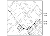
図9は、実測した移動軌跡と本実施形態の座標変換システムで生成した推定移動軌跡との対応を示す図である。
図9において、座標点501Pが実測により測定した移動点であり、座標点502Pが推定移動軌跡における移動点である。
また、線分501Lが実測により測定した移動点を連結した線分であり、線分502Lが推定移動軌跡における移動点を連結した線分である。
本実施形態による推定移動軌跡が、実測した移動軌跡に対し、移動点の位置及び軌跡の形状が良く対応していることが図9から判る。
FIG. 9 is a diagram showing the correspondence between an actually measured movement trajectory and an estimated movement trajectory generated by the coordinate transformation system of this embodiment.
In FIG. 9, coordinate
A
It can be seen from FIG. 9 that the estimated movement trajectory according to this embodiment corresponds well to the actually measured movement trajectory in terms of the positions of the moving points and the shape of the trajectory.
上述した座標変換システムは、第2座標系における撮像画像データから生成した第2移動軌跡を、所定の数の座標点から構成される分割第2移動軌跡に分割し、当該分割第2移動軌跡における座標点の各々と、GPSデータにより生成した第1移動軌跡の同一のID番号を有する座標点のそれぞれとの距離(あるいは距離の二乗)の合計値が最小となる第1座標系における位置に、分割第2移動軌跡における座標点を線形変換させる変換行列を生成し、この変換行列の各々の同一の列及び行の位置にある要素のスカラー値を系列とし、ガウス過程を用いて隣接した分割第2移動軌跡に対応した変換行列間におけるスカラー値の変化量を低減させて新たな補正変換行列を生成し、この補正変換行列により分割第2移動軌跡を第2変換行列から第1変換行列に座標変換することにより、第1移動軌跡の有するGPSデータの絶対位置の情報により、第2移動軌跡のスケールドリフトの影響が分割第2移動軌跡に分割した各々において解消し、かつ第2移動軌跡が有する局所的に正しい移動軌跡の変化形状の情報が反映され、かつガウス過程によるノイズの低減とにより、第1移動軌跡におけるノイズが平滑化され、GPSによるノイズを含む歪んだ形状が整形され、絶対位置の情報及び相対的な変化形状との双方を有する(すなわち、絶対位置を有した相対的な移動変化が滑らかな形状として)、移動体の推定移動軌跡を得ることができる。 The above-mentioned coordinate transformation system divides the second movement trajectory generated from the captured image data in the second coordinate system into divided second movement trajectories consisting of a predetermined number of coordinate points, generates a transformation matrix that linearly transforms the coordinate points in the divided second movement trajectory to positions in the first coordinate system where the sum of the distances (or the squares of the distances) between each of the coordinate points in the divided second movement trajectory and each of the coordinate points having the same ID number in the first movement trajectory generated from the GPS data is the smallest, and generates a new correction transformation matrix by treating the scalar values of the elements in the same column and row positions of each of the transformation matrices as a series and reducing the amount of change in scalar values between the transformation matrices corresponding to adjacent divided second movement trajectories using a Gaussian process. By performing coordinate transformation of the divided second movement trajectory from the second transformation matrix to the first transformation matrix using this correction transformation matrix, the influence of scale drift of the second movement trajectory is eliminated in each of the divided second movement trajectories due to the absolute position information of the GPS data of the first movement trajectory, and locally correct information on the changing shape of the movement trajectory of the second movement trajectory is reflected. Furthermore, by reducing noise using the Gaussian process, the noise in the first movement trajectory is smoothed, and the distorted shape including noise due to GPS is shaped, and an estimated movement trajectory of the moving body having both absolute position information and relative changing shape (i.e., a shape with smooth relative movement changes having absolute position) can be obtained.
<第3の実施形態>
以下、本発明の第3の実施形態による座標変換システムについて説明する。第3の実施形態の座標変換システムの構成は、図6に示す第2の実施形態の構成と同様である。
以下、第2の実施形態と異なる動作の説明を行う。
第2の実施形態においては、変換行列M1~Mnの各々における要素(変数)の系列(x1_ij,x2_ij,x2_ij,…,xn_ij)の隣接するスカラー値の平滑化をガウス過程を用いて行ったが、第3の実施形態においてはカルマンフィルタを用いて行う。第2移動軌跡から生成した分割第2移動軌跡の各々に対応して、変換行列M1からMnのそれぞれは、第2移動軌跡における移動体の進行方向に向かって、符号の順番で連続した関係を有している。
Third Embodiment
A coordinate transformation system according to a third embodiment of the present invention will now be described. The configuration of the coordinate transformation system of the third embodiment is similar to that of the second embodiment shown in FIG.
The following describes operations that differ from the second embodiment.
In the second embodiment, the smoothing of adjacent scalar values of the series of elements (variables) (x1_ij, x2_ij, x2_ij, ..., xn_ij) in each of the transformation matrices M1 to Mn was performed using a Gaussian process, but in the third embodiment, it is performed using a Kalman filter. Corresponding to each of the divided second movement trajectories generated from the second movement trajectory, each of the transformation matrices M1 to Mn has a continuous relationship in the order of the signs toward the moving direction of the moving body on the second movement trajectory.
すなわち、変換行列補正部112は、カルマンフィルタに推定値r(k-1)_ijとスカラー値r(k-1)_ijとを入力し、推定値r(k)_ijを得る処理を行う。ここで、1≦k≦nであり、k及びnは整数である。スカラー値r(k-1)_ijは、変換行列Mk-1の第i行目、第j列目の要素のスカラー値である。推定値r(k-1)_ijは、変換行列Mkの第i行目、第j列目における要素の推定値である。
そして、上記カルマンフィルタは、変換行列Mk-1の第i行目、第j列目の要素のスカラー値と、変換行列Mk-1の第i行目、第j列目の要素の推定値とから、変換行列Mkの第i行目、第j列目の要素の推定値r(k)_ijを指定して出力する。
That is, the transformation matrix correction unit 112 inputs the estimated value r(k-1)_ij and the scalar value r(k-1)_ij to the Kalman filter, and performs processing to obtain the estimated value r(k)_ij. Here, 1≦k≦n, and k and n are integers. The scalar value r(k-1)_ij is the scalar value of the element in the i-th row and j-th column of the transformation matrix Mk-1. The estimated value r(k-1)_ij is the estimated value of the element in the i-th row and j-th column of the transformation matrix Mk.
The Kalman filter then specifies and outputs an estimated value r(k)_ij of the element in the i-th row and j-th column of the transformation matrix Mk, based on the scalar value of the element in the i-th row and j-th column of the transformation matrix Mk-1 and the estimated value of the element in the i-th row and j-th column of the transformation matrix Mk-1.
上述したように、変換行列補正部112は、カルマンフィルタを用いて、系列(x1_ij,x2_ij,x2_ij,…,xn_ij)から、補正系列(x1_ij’,x2_ij,x2_ij’,…,xn_ij’)を求める。
そして、変換行列補正部112は、変換行列M1からMnの各々の行及び列における要素の全てに対する補正系列を用いて、補正変換行列M1’からMn’の各々を生成する。
変換行列補正部112は、生成した補正変換行列M1’からMn’の各々を、変換行列記憶部111に対して書き込んで記憶させる。
As described above, the transformation matrix correction unit 112 uses a Kalman filter to obtain a corrected sequence (x1_ij', x2_ij, x2_ij', ..., xn_ij') from the sequence (x1_ij, x2_ij, x2_ij, ..., xn_ij).
Then, the transformation matrix correction unit 112 generates each of the corrected transformation matrices M1' to Mn' using the correction sequence for all of the elements in the rows and columns of each of the transformation matrices M1 to Mn.
The transformation matrix correction unit 112 writes each of the generated corrected transformation matrices M1' to Mn' into the transformation
上述した座標変換システムは、第2座標系における撮像画像データから生成した第2移動軌跡を、所定の数の座標点から構成される分割第2移動軌跡に分割し、当該分割第2移動軌跡における座標点の各々と、GPSデータにより生成した第1移動軌跡の同一のID番号を有する座標点のそれぞれとの距離(あるいは距離の二乗)の合計値が最小となる第1座標系における位置に、分割第2移動軌跡における座標点を線形変換させる変換行列を生成し、この変換行列の各々の同一の列及び行の位置にある要素のスカラー値を系列とし、カルマンフィルタを用いて隣接した分割第2移動軌跡に対応した変換行列間におけるスカラー値を推定させて新たな補正変換行列を生成し、この補正変換行列により分割第2移動軌跡を第2変換行列から第1変換行列に座標変換することにより、第1移動軌跡の有するGPSデータの絶対位置の情報により、第2移動軌跡のスケールドリフトの影響が分割第2移動軌跡に分割した各々において解消し、かつ第2移動軌跡が有する局所的に正しい移動軌跡の変化形状の情報が反映され、かつカルマンフィルタによるノイズの低減により、第1移動軌跡におけるノイズが平滑化され、GPSによるノイズを含む歪んだ形状が整形され、絶対位置の情報及び相対的な変化形状との双方を有する(すなわち、絶対位置を有した相対的な移動変化が滑らかな形状として)、移動体の推定移動軌跡を得ることができる。 The coordinate transformation system described above divides the second movement trajectory generated from the captured image data in the second coordinate system into divided second movement trajectories consisting of a predetermined number of coordinate points, generates a transformation matrix that linearly transforms the coordinate points in the divided second movement trajectory to positions in the first coordinate system where the sum of the distances (or squares of the distances) between each of the coordinate points in the divided second movement trajectory and each of the coordinate points having the same ID number in the first movement trajectory generated from the GPS data is the smallest, and generates a new correction transformation matrix by estimating the scalar values between the transformation matrices corresponding to adjacent divided second movement trajectories using a Kalman filter. Then, by performing coordinate transformation of the divided second movement trajectory from the second transformation matrix to the first transformation matrix using this correction transformation matrix, the influence of scale drift of the second movement trajectory is eliminated in each of the divided second movement trajectories due to the absolute position information of the GPS data of the first movement trajectory, and locally correct information on the changing shape of the movement trajectory of the second movement trajectory is reflected, and noise in the first movement trajectory is smoothed by reducing noise using a Kalman filter, and the distorted shape including noise due to GPS is shaped, so that an estimated movement trajectory of the moving body having both absolute position information and a relative changing shape (i.e., a shape with smooth relative movement changes having absolute positions) can be obtained.
以上、本発明の実施形態を図面を参照し説明してきたが、具体的な構成はこの形態に限られるものではなく、この発明の要旨を逸脱しない範囲の設計なども含まれる。
本実施形態においては、第1座標系及び第2座標系の各々を3次元空間を示す3次元座標系として示したが、2次元座標系として構成してもよい。この場合、第1座標系の場合には、緯度及び経度の示す2次元平面に対応し、第2座標系は2次元平面上における移動軌跡の形状を示す。
Although the embodiment of the present invention has been described above with reference to the drawings, the specific configuration is not limited to this embodiment, and designs within the scope of the present invention that do not deviate from the gist of the present invention are also included.
In this embodiment, the first coordinate system and the second coordinate system are each shown as a three-dimensional coordinate system indicating a three-dimensional space, but they may be configured as two-dimensional coordinate systems. In this case, the first coordinate system corresponds to a two-dimensional plane indicated by latitude and longitude, and the second coordinate system indicates the shape of a movement trajectory on the two-dimensional plane.
なお、本発明における図1の座標変換システム100及び図6の座標変換システム100Aの各々の機能をそれぞれ実現するためのプログラムをコンピュータ読み取り可能な記録媒体に記録して、この記録媒体に記録されたプログラムをコンピュータシステムに読み込ませ、実行することによりGPSデータ及び撮像画像データにより移動体の移動軌跡を推定する処理を行ってもよい。なお、ここでいう「コンピュータシステム」とは、OSや周辺機器等のハードウェアを含むものとする。
In addition, a program for implementing the functions of the coordinate
また、「コンピュータシステム」は、ホームページ提供環境(あるいは表示環境)を備えたWWWシステムも含むものとする。また、「コンピュータ読み取り可能な記録媒体」とは、フレキシブルディスク、光磁気ディスク、ROM、CD-ROM等の可搬媒体、コンピュータシステムに内蔵されるハードディスク等の記憶装置のことをいう。さらに「コンピュータ読み取り可能な記録媒体」とは、インターネット等のネットワークや電話回線等の通信回線を介してプログラムが送信された場合のサーバやクライアントとなるコンピュータシステム内部の揮発性メモリ(RAM)のように、一定時間プログラムを保持しているものも含むものとする。 "Computer system" also includes a WWW system equipped with a homepage provision environment (or display environment). "Computer-readable recording medium" refers to portable media such as flexible disks, optical magnetic disks, ROMs, and CD-ROMs, as well as storage devices such as hard disks built into computer systems. "Computer-readable recording medium" also includes devices that hold a program for a certain period of time, such as volatile memory (RAM) inside a computer system that serves as a server or client when a program is transmitted via a network such as the Internet or a communication line such as a telephone line.
また、上記プログラムは、このプログラムを記憶装置等に格納したコンピュータシステムから、伝送媒体を介して、あるいは、伝送媒体中の伝送波により他のコンピュータシステムに伝送されてもよい。ここで、プログラムを伝送する「伝送媒体」は、インターネット等のネットワーク(通信網)や電話回線等の通信回線(通信線)のように情報を伝送する機能を有する媒体のことをいう。また、上記プログラムは、前述した機能の一部を実現するためのものであっても良い。さらに、前述した機能をコンピュータシステムにすでに記録されているプログラムとの組み合わせで実現できるもの、いわゆる差分ファイル(差分プログラム)であっても良い。 The above program may also be transmitted from a computer system in which the program is stored in a storage device or the like to another computer system via a transmission medium, or by transmission waves in the transmission medium. Here, the "transmission medium" that transmits the program refers to a medium that has the function of transmitting information, such as a network (communication network) such as the Internet or a communication line (communication line) such as a telephone line. The above program may also be one that realizes part of the above-mentioned functions. Furthermore, it may be a so-called difference file (difference program) that can realize the above-mentioned functions in combination with a program already recorded in the computer system.
100,100A…座標変換システム
101…データ入出力部
102…第1移動軌跡生成部
103…第2移動軌跡生成部
104…第2移動軌跡分割部
105…変換行列生成部
106…座標変換部
107…表示部
108…GPSデータ記憶部
109…撮像画像データ記憶部
110…移動軌跡データ記憶部
111…変換行列記憶部
112…変換行列補正部
REFERENCE SIGNS
Claims (6)
移動する風景を撮像した時系列な撮像画像の各々を用いて、前記移動体の相対的な位置の変化を示す第2座標系における第2移動軌跡を生成する第2移動軌跡生成部と、
前記第2移動軌跡を所定の幅に分割して分割第2移動軌跡の各々を生成する第2移動軌跡分割部と、
前記第1移動軌跡の座標点のそれぞれとの距離の合計値が最小または距離の二乗の合計値が最小となる第1座標系における位置に、前記第1移動軌跡の座標点の識別番号と同一の識別番号を有する前記分割第2移動軌跡における座標点を線形変換させる変換行列を生成する変換行列生成部と、
前記変換行列により前記分割第2移動軌跡の各々を、第1座標系における前記第1移動軌跡の対応する部分に合わせて線形座標変換を行い、前記移動体の移動の軌跡を推定した推定移動軌跡を生成する座標変換部と、
を備えることを特徴とする座標変換システム。 a first movement trajectory generation unit that generates a first movement trajectory in a first coordinate system of real distance by using each of time-series movement positions of the moving object measured by a GPS (Global Positioning System);
a second movement trajectory generation unit that generates a second movement trajectory in a second coordinate system that indicates a change in a relative position of the moving object, using each of time-series captured images of a moving landscape;
a second trajectory division unit that divides the second trajectory into predetermined widths to generate divided second trajectories;
a transformation matrix generating unit that generates a transformation matrix for linearly transforming a coordinate point on the divided second movement trajectory having an identification number identical to an identification number of a coordinate point on the first movement trajectory to a position in a first coordinate system where a total value of distances to each of the coordinate points on the first movement trajectory or a total value of squares of distances to each of the coordinate points on the first movement trajectory is minimum;
a coordinate transformation unit that performs linear coordinate transformation on each of the divided second trajectories by using the transformation matrix to match a corresponding portion of the first trajectory in a first coordinate system, thereby generating an estimated trajectory that estimates a trajectory of movement of the moving object;
A coordinate transformation system comprising:
前記座標変換部が、
前記分割第2移動軌跡の各々を、前記第2座標系から前記第1座標系における前記第1移動軌跡に対応して線形変換する前記変換行列を生成し、
前記変換行列補正部が、隣接する分割第2移動軌跡の各々の前記変換行列における要素それぞれの変化量を低減する補正を行い、
前記座標変換部が、
前記変換行列補正部が補正した前記変換行列を用いて、前記分割第2移動軌跡の座標変換を行い、前記推定移動軌跡を生成する
ことを特徴とする請求項1に記載の座標変換システム。 a transformation matrix correction unit that corrects a transformation matrix that performs coordinate transformation on each of the divided second movement trajectories so as to correspond to a portion of the first movement trajectory in a first coordinate system;
The coordinate conversion unit
generating the transformation matrix that linearly transforms each of the divided second movement trajectories from the second coordinate system to correspond to the first movement trajectory in the first coordinate system;
the transformation matrix correction unit performs a correction to reduce an amount of change in each of the elements in the transformation matrix of each of the adjacent divided second movement trajectories;
The coordinate conversion unit
The coordinate transformation system according to claim 1 , further comprising: a transformation matrix correction unit that performs coordinate transformation of the divided second trajectory using the transformation matrix corrected by the transformation matrix correction unit to generate the estimated trajectory.
隣接する分割第2移動軌跡の各々の前記変換行列における要素のそれぞれを、より変化量が低減された数値とする関数をガウス過程により求め、前記変換行列の前記要素を当該関数により算出する
ことを特徴とする請求項2に記載の座標変換システム。 The transformation matrix correction unit:
The coordinate transformation system according to claim 2, characterized in that a function that reduces the amount of change in each of the elements in the transformation matrix of each of the adjacent divided second movement trajectories is obtained using a Gaussian process, and the elements of the transformation matrix are calculated using the function.
隣接する分割第2移動軌跡の各々の前記変換行列における要素を、連続する前記分割第2移動軌跡それぞれの当該変換行列の元々の要素を用いてカルマンフィルタにより推定した数値にとする
ことを特徴とする請求項2に記載の座標変換システム。 The transformation matrix correction unit:
The coordinate transformation system according to claim 2, characterized in that elements in the transformation matrix of each of the adjacent divided second movement trajectories are set to values estimated by a Kalman filter using original elements of the transformation matrix of each of the consecutive divided second movement trajectories.
第2移動軌跡生成部が、移動する風景を撮像した時系列な撮像画像の各々を用いて、前記移動体の相対的な位置の変化を示す第2座標系における第2移動軌跡を生成する第2移動軌跡生成過程と、
第2移動軌跡分割部が、前記第2移動軌跡を所定の幅に分割して分割第2移動軌跡の各々を生成する第2移動軌跡分割過程と、
変換行列生成部が、前記第1移動軌跡の座標点のそれぞれとの距離の合計値が最小または距離の二乗の合計値が最小となる第1座標系における位置に、前記第1移動軌跡の座標点の識別番号と同一の識別番号を有する前記分割第2移動軌跡における座標点を線形変換させる変換行列を生成する変換行列生成過程と、
座標変換部が、前記変換行列により前記分割第2移動軌跡の各々を、第1座標系における前記第1移動軌跡の対応する部分に合わせて線形座標変換を行い、前記移動体の移動の軌跡を推定した推定移動軌跡を生成する座標変換過程と、
を含むことを特徴とする座標変換方法。 a first movement trajectory generation step in which a first movement trajectory generation unit generates a first movement trajectory in a first coordinate system of real distance by using each of time-series movement positions of the moving object measured by a GPS (Global Positioning System);
a second movement trajectory generation step in which a second movement trajectory generation unit generates a second movement trajectory in a second coordinate system indicating a change in a relative position of the moving object, using each of time-series captured images of a moving landscape;
a second trajectory division step of dividing the second trajectory into a predetermined width to generate each divided second trajectory;
a transformation matrix generation step in which a transformation matrix generation unit generates a transformation matrix for linearly transforming a coordinate point on the divided second movement trajectory having an identification number identical to an identification number of a coordinate point on the first movement trajectory to a position in a first coordinate system where a total value of distances to each of the coordinate points on the first movement trajectory is minimum or a total value of squares of distances is minimum;
a coordinate transformation step in which a coordinate transformation unit performs linear coordinate transformation on each of the divided second trajectories by using the transformation matrix to match a corresponding portion of the first trajectory in a first coordinate system, thereby generating an estimated trajectory that estimates a trajectory of movement of the moving object;
A coordinate transformation method comprising:
GPS(Global Positioning System)により計測した移動体の時系列な移動位置の各々を用いて、実距離の第1座標系における第1移動軌跡を生成する第1移動軌跡生成手段、
移動する風景を撮像した時系列な撮像画像の各々を用いて、前記移動体の相対的な位置の変化を示す第2座標系における第2移動軌跡を生成する第2移動軌跡生成手段、
前記第2移動軌跡を所定の幅に分割して分割第2移動軌跡の各々を生成する第2移動軌跡分割手段、
前記第1移動軌跡の座標点のそれぞれとの距離の合計値が最小または距離の二乗の合計値が最小となる第1座標系における位置に、前記第1移動軌跡の座標点の識別番号と同一の識別番号を有する前記分割第2移動軌跡における座標点を線形変換させる変換行列を生成する変換行列生成手段、
前記変換行列により前記分割第2移動軌跡の各々を、第1座標系における前記第1移動軌跡の対応する部分に合わせて線形座標変換を行い、前記移動体の移動の軌跡を推定した推定移動軌跡を生成する座標変換手段、
として機能させるプログラム。 Computer,
a first movement trajectory generating means for generating a first movement trajectory in a first coordinate system of real distance by using each of time-series movement positions of the moving object measured by a GPS (Global Positioning System);
a second movement trajectory generating means for generating a second movement trajectory in a second coordinate system indicating a change in a relative position of the moving object, using each of time-series captured images of a moving landscape;
a second movement trajectory dividing means for dividing the second movement trajectory into a predetermined width to generate each divided second movement trajectory;
a transformation matrix generating means for generating a transformation matrix for linearly transforming a coordinate point on the divided second movement trajectory having the same identification number as an identification number of a coordinate point on the first movement trajectory to a position in the first coordinate system where the sum of distances to each of the coordinate points on the first movement trajectory is the smallest or the sum of squares of distances is the smallest;
a coordinate transformation means for performing linear coordinate transformation on each of the divided second trajectories in accordance with the transformation matrix to match a corresponding portion of the first trajectory in a first coordinate system, thereby generating an estimated trajectory of the trajectory of the movement of the moving object;
A program that functions as a
Priority Applications (1)
| Application Number | Priority Date | Filing Date | Title |
|---|---|---|---|
| JP2020192745A JP7591908B2 (en) | 2020-11-19 | 2020-11-19 | Coordinate conversion system, coordinate conversion method and program |
Applications Claiming Priority (1)
| Application Number | Priority Date | Filing Date | Title |
|---|---|---|---|
| JP2020192745A JP7591908B2 (en) | 2020-11-19 | 2020-11-19 | Coordinate conversion system, coordinate conversion method and program |
Publications (2)
| Publication Number | Publication Date |
|---|---|
| JP2022081296A JP2022081296A (en) | 2022-05-31 |
| JP7591908B2 true JP7591908B2 (en) | 2024-11-29 |
Family
ID=81799392
Family Applications (1)
| Application Number | Title | Priority Date | Filing Date |
|---|---|---|---|
| JP2020192745A Active JP7591908B2 (en) | 2020-11-19 | 2020-11-19 | Coordinate conversion system, coordinate conversion method and program |
Country Status (1)
| Country | Link |
|---|---|
| JP (1) | JP7591908B2 (en) |
Families Citing this family (2)
| Publication number | Priority date | Publication date | Assignee | Title |
|---|---|---|---|---|
| WO2024181473A1 (en) * | 2023-03-02 | 2024-09-06 | Necソリューションイノベータ株式会社 | Information processing device, information processing method, and computer-readable recording medium |
| CN116839612B (en) * | 2023-06-30 | 2026-01-06 | 惠州市德赛西威汽车电子股份有限公司 | A method, apparatus, vehicle, and storage medium for determining vehicle waypoints |
Citations (6)
| Publication number | Priority date | Publication date | Assignee | Title |
|---|---|---|---|---|
| JP2011043419A (en) | 2009-08-21 | 2011-03-03 | Sony Corp | Information processor, information processing method, and program |
| JP2013537995A (en) | 2010-09-24 | 2013-10-07 | エボリューション・ロボティクス・インコーポレイテッド | System and method for VSLAM optimization |
| JP2018517979A (en) | 2015-05-22 | 2018-07-05 | コンティネンタル・テーベス・アクチエンゲゼルシヤフト・ウント・コンパニー・オッフェネ・ハンデルスゲゼルシヤフト | Method for estimating driving lane |
| JP2018124787A (en) | 2017-01-31 | 2018-08-09 | 富士通株式会社 | Information processing apparatus, data management apparatus, data management system, method, and program |
| JP2020067439A (en) | 2018-10-26 | 2020-04-30 | 富士通株式会社 | System and method for estimating position of moving body |
| JP2020153956A (en) | 2019-03-22 | 2020-09-24 | 富士通株式会社 | Moving body position estimation system and moving body position estimation method |
-
2020
- 2020-11-19 JP JP2020192745A patent/JP7591908B2/en active Active
Patent Citations (6)
| Publication number | Priority date | Publication date | Assignee | Title |
|---|---|---|---|---|
| JP2011043419A (en) | 2009-08-21 | 2011-03-03 | Sony Corp | Information processor, information processing method, and program |
| JP2013537995A (en) | 2010-09-24 | 2013-10-07 | エボリューション・ロボティクス・インコーポレイテッド | System and method for VSLAM optimization |
| JP2018517979A (en) | 2015-05-22 | 2018-07-05 | コンティネンタル・テーベス・アクチエンゲゼルシヤフト・ウント・コンパニー・オッフェネ・ハンデルスゲゼルシヤフト | Method for estimating driving lane |
| JP2018124787A (en) | 2017-01-31 | 2018-08-09 | 富士通株式会社 | Information processing apparatus, data management apparatus, data management system, method, and program |
| JP2020067439A (en) | 2018-10-26 | 2020-04-30 | 富士通株式会社 | System and method for estimating position of moving body |
| JP2020153956A (en) | 2019-03-22 | 2020-09-24 | 富士通株式会社 | Moving body position estimation system and moving body position estimation method |
Also Published As
| Publication number | Publication date |
|---|---|
| JP2022081296A (en) | 2022-05-31 |
Similar Documents
| Publication | Publication Date | Title |
|---|---|---|
| JP7271244B2 (en) | CNN processing device, CNN processing method, and program | |
| JP2006091011A (en) | Multi-view parallax display | |
| CN114556421A (en) | Scene representation using image processing | |
| JP2006260527A (en) | Image matching method and image interpolation method using the same | |
| JP7591908B2 (en) | Coordinate conversion system, coordinate conversion method and program | |
| CN112508996A (en) | Target tracking method and device for anchor-free twin network corner generation | |
| JP7622837B2 (en) | Object detection device and method | |
| US8036454B2 (en) | Information processing system | |
| El Akkad et al. | Reconstruction of 3D scenes by camera self-calibration and using genetic algorithms | |
| CN109087344B (en) | Image selection method and device in three-dimensional reconstruction | |
| TWI462056B (en) | Image processing method, apparatus, and computer program product | |
| Jia et al. | A novel dynamic multilevel technique for image registration | |
| CN111090688A (en) | Smoothing processing method and device for time sequence data | |
| CN110428461B (en) | Monocular SLAM method and device combined with deep learning | |
| JP2009109200A (en) | Position / orientation estimation system, position / orientation estimation device, and position / orientation estimation method | |
| CN111028346B (en) | A method and device for reconstructing video objects | |
| JP2016157174A (en) | Three-dimensional space data interpolation program and shape generation program achieved by combining the same | |
| WO2020149044A1 (en) | Parameter selection device, parameter selection method, and parameter selection program | |
| CN115205419A (en) | Instant positioning and map construction method and device, electronic equipment and readable storage medium | |
| Tan et al. | Improved shape-from-template method with perspective space constraints for disappearing features | |
| CN119559100A (en) | Image processing method, device, storage medium and program product | |
| CN113592710B (en) | A method and device for enhancing spatiotemporal trajectory data quality based on deep learning | |
| JP2020041950A (en) | Surveying device, surveying method, and program | |
| CN113537351B (en) | Coordinate matching method for remote sensing images captured by mobile devices | |
| Broxton et al. | 3d lunar terrain reconstruction from apollo images |
Legal Events
| Date | Code | Title | Description |
|---|---|---|---|
| A621 | Written request for application examination |
Free format text: JAPANESE INTERMEDIATE CODE: A621 Effective date: 20231016 |
|
| A977 | Report on retrieval |
Free format text: JAPANESE INTERMEDIATE CODE: A971007 Effective date: 20240221 |
|
| A131 | Notification of reasons for refusal |
Free format text: JAPANESE INTERMEDIATE CODE: A131 Effective date: 20240305 |
|
| A601 | Written request for extension of time |
Free format text: JAPANESE INTERMEDIATE CODE: A601 Effective date: 20240502 |
|
| A521 | Request for written amendment filed |
Free format text: JAPANESE INTERMEDIATE CODE: A523 Effective date: 20240703 |
|
| A131 | Notification of reasons for refusal |
Free format text: JAPANESE INTERMEDIATE CODE: A131 Effective date: 20240806 |
|
| A521 | Request for written amendment filed |
Free format text: JAPANESE INTERMEDIATE CODE: A523 Effective date: 20241001 |
|
| TRDD | Decision of grant or rejection written | ||
| A01 | Written decision to grant a patent or to grant a registration (utility model) |
Free format text: JAPANESE INTERMEDIATE CODE: A01 Effective date: 20241022 |
|
| A61 | First payment of annual fees (during grant procedure) |
Free format text: JAPANESE INTERMEDIATE CODE: A61 Effective date: 20241119 |
|
| R150 | Certificate of patent or registration of utility model |
Ref document number: 7591908 Country of ref document: JP Free format text: JAPANESE INTERMEDIATE CODE: R150 |