JP7589757B2 - Laminated material - Google Patents
Laminated material Download PDFInfo
- Publication number
- JP7589757B2 JP7589757B2 JP2022576695A JP2022576695A JP7589757B2 JP 7589757 B2 JP7589757 B2 JP 7589757B2 JP 2022576695 A JP2022576695 A JP 2022576695A JP 2022576695 A JP2022576695 A JP 2022576695A JP 7589757 B2 JP7589757 B2 JP 7589757B2
- Authority
- JP
- Japan
- Prior art keywords
- glass
- mol
- sic
- less
- laminated
- Prior art date
- Legal status (The legal status is an assumption and is not a legal conclusion. Google has not performed a legal analysis and makes no representation as to the accuracy of the status listed.)
- Active
Links
Images

Classifications
-
- B—PERFORMING OPERATIONS; TRANSPORTING
- B32—LAYERED PRODUCTS
- B32B—LAYERED PRODUCTS, i.e. PRODUCTS BUILT-UP OF STRATA OF FLAT OR NON-FLAT, e.g. CELLULAR OR HONEYCOMB, FORM
- B32B17/00—Layered products essentially comprising sheet glass, or glass, slag, or like fibres
- B32B17/06—Layered products essentially comprising sheet glass, or glass, slag, or like fibres comprising glass as the main or only constituent of a layer, next to another layer of a specific material
- B32B17/10—Layered products essentially comprising sheet glass, or glass, slag, or like fibres comprising glass as the main or only constituent of a layer, next to another layer of a specific material of synthetic resin
-
- B—PERFORMING OPERATIONS; TRANSPORTING
- B32—LAYERED PRODUCTS
- B32B—LAYERED PRODUCTS, i.e. PRODUCTS BUILT-UP OF STRATA OF FLAT OR NON-FLAT, e.g. CELLULAR OR HONEYCOMB, FORM
- B32B18/00—Layered products essentially comprising ceramics, e.g. refractory products
-
- B—PERFORMING OPERATIONS; TRANSPORTING
- B32—LAYERED PRODUCTS
- B32B—LAYERED PRODUCTS, i.e. PRODUCTS BUILT-UP OF STRATA OF FLAT OR NON-FLAT, e.g. CELLULAR OR HONEYCOMB, FORM
- B32B7/00—Layered products characterised by the relation between layers; Layered products characterised by the relative orientation of features between layers, or by the relative values of a measurable parameter between layers, i.e. products comprising layers having different physical, chemical or physicochemical properties; Layered products characterised by the interconnection of layers
- B32B7/02—Physical, chemical or physicochemical properties
- B32B7/022—Mechanical properties
-
- B—PERFORMING OPERATIONS; TRANSPORTING
- B32—LAYERED PRODUCTS
- B32B—LAYERED PRODUCTS, i.e. PRODUCTS BUILT-UP OF STRATA OF FLAT OR NON-FLAT, e.g. CELLULAR OR HONEYCOMB, FORM
- B32B7/00—Layered products characterised by the relation between layers; Layered products characterised by the relative orientation of features between layers, or by the relative values of a measurable parameter between layers, i.e. products comprising layers having different physical, chemical or physicochemical properties; Layered products characterised by the interconnection of layers
- B32B7/02—Physical, chemical or physicochemical properties
- B32B7/023—Optical properties
-
- B—PERFORMING OPERATIONS; TRANSPORTING
- B32—LAYERED PRODUCTS
- B32B—LAYERED PRODUCTS, i.e. PRODUCTS BUILT-UP OF STRATA OF FLAT OR NON-FLAT, e.g. CELLULAR OR HONEYCOMB, FORM
- B32B7/00—Layered products characterised by the relation between layers; Layered products characterised by the relative orientation of features between layers, or by the relative values of a measurable parameter between layers, i.e. products comprising layers having different physical, chemical or physicochemical properties; Layered products characterised by the interconnection of layers
- B32B7/02—Physical, chemical or physicochemical properties
- B32B7/027—Thermal properties
-
- B—PERFORMING OPERATIONS; TRANSPORTING
- B32—LAYERED PRODUCTS
- B32B—LAYERED PRODUCTS, i.e. PRODUCTS BUILT-UP OF STRATA OF FLAT OR NON-FLAT, e.g. CELLULAR OR HONEYCOMB, FORM
- B32B7/00—Layered products characterised by the relation between layers; Layered products characterised by the relative orientation of features between layers, or by the relative values of a measurable parameter between layers, i.e. products comprising layers having different physical, chemical or physicochemical properties; Layered products characterised by the interconnection of layers
- B32B7/04—Interconnection of layers
- B32B7/12—Interconnection of layers using interposed adhesives or interposed materials with bonding properties
-
- B—PERFORMING OPERATIONS; TRANSPORTING
- B32—LAYERED PRODUCTS
- B32B—LAYERED PRODUCTS, i.e. PRODUCTS BUILT-UP OF STRATA OF FLAT OR NON-FLAT, e.g. CELLULAR OR HONEYCOMB, FORM
- B32B9/00—Layered products comprising a layer of a particular substance not covered by groups B32B11/00 - B32B29/00
- B32B9/005—Layered products comprising a layer of a particular substance not covered by groups B32B11/00 - B32B29/00 comprising one layer of ceramic material, e.g. porcelain, ceramic tile
-
- B—PERFORMING OPERATIONS; TRANSPORTING
- B32—LAYERED PRODUCTS
- B32B—LAYERED PRODUCTS, i.e. PRODUCTS BUILT-UP OF STRATA OF FLAT OR NON-FLAT, e.g. CELLULAR OR HONEYCOMB, FORM
- B32B9/00—Layered products comprising a layer of a particular substance not covered by groups B32B11/00 - B32B29/00
- B32B9/04—Layered products comprising a layer of a particular substance not covered by groups B32B11/00 - B32B29/00 comprising such particular substance as the main or only constituent of a layer, which is next to another layer of the same or of a different material
- B32B9/045—Layered products comprising a layer of a particular substance not covered by groups B32B11/00 - B32B29/00 comprising such particular substance as the main or only constituent of a layer, which is next to another layer of the same or of a different material of synthetic resin
-
- C—CHEMISTRY; METALLURGY
- C03—GLASS; MINERAL OR SLAG WOOL
- C03C—CHEMICAL COMPOSITION OF GLASSES, GLAZES OR VITREOUS ENAMELS; SURFACE TREATMENT OF GLASS; SURFACE TREATMENT OF FIBRES OR FILAMENTS MADE FROM GLASS, MINERALS OR SLAGS; JOINING GLASS TO GLASS OR OTHER MATERIALS
- C03C27/00—Joining pieces of glass to pieces of other inorganic material; Joining glass to glass other than by fusing
-
- C—CHEMISTRY; METALLURGY
- C03—GLASS; MINERAL OR SLAG WOOL
- C03C—CHEMICAL COMPOSITION OF GLASSES, GLAZES OR VITREOUS ENAMELS; SURFACE TREATMENT OF GLASS; SURFACE TREATMENT OF FIBRES OR FILAMENTS MADE FROM GLASS, MINERALS OR SLAGS; JOINING GLASS TO GLASS OR OTHER MATERIALS
- C03C3/00—Glass compositions
- C03C3/04—Glass compositions containing silica
- C03C3/06—Glass compositions containing silica with more than 90% silica by weight, e.g. quartz
-
- C—CHEMISTRY; METALLURGY
- C03—GLASS; MINERAL OR SLAG WOOL
- C03C—CHEMICAL COMPOSITION OF GLASSES, GLAZES OR VITREOUS ENAMELS; SURFACE TREATMENT OF GLASS; SURFACE TREATMENT OF FIBRES OR FILAMENTS MADE FROM GLASS, MINERALS OR SLAGS; JOINING GLASS TO GLASS OR OTHER MATERIALS
- C03C3/00—Glass compositions
- C03C3/04—Glass compositions containing silica
- C03C3/076—Glass compositions containing silica with 40% to 90% silica, by weight
- C03C3/083—Glass compositions containing silica with 40% to 90% silica, by weight containing aluminium oxide or an iron compound
- C03C3/085—Glass compositions containing silica with 40% to 90% silica, by weight containing aluminium oxide or an iron compound containing an oxide of a divalent metal
- C03C3/087—Glass compositions containing silica with 40% to 90% silica, by weight containing aluminium oxide or an iron compound containing an oxide of a divalent metal containing calcium oxide, e.g. common sheet or container glass
-
- C—CHEMISTRY; METALLURGY
- C03—GLASS; MINERAL OR SLAG WOOL
- C03C—CHEMICAL COMPOSITION OF GLASSES, GLAZES OR VITREOUS ENAMELS; SURFACE TREATMENT OF GLASS; SURFACE TREATMENT OF FIBRES OR FILAMENTS MADE FROM GLASS, MINERALS OR SLAGS; JOINING GLASS TO GLASS OR OTHER MATERIALS
- C03C3/00—Glass compositions
- C03C3/04—Glass compositions containing silica
- C03C3/076—Glass compositions containing silica with 40% to 90% silica, by weight
- C03C3/089—Glass compositions containing silica with 40% to 90% silica, by weight containing boron
- C03C3/091—Glass compositions containing silica with 40% to 90% silica, by weight containing boron containing aluminium
- C03C3/093—Glass compositions containing silica with 40% to 90% silica, by weight containing boron containing aluminium containing zinc or zirconium
-
- C—CHEMISTRY; METALLURGY
- C03—GLASS; MINERAL OR SLAG WOOL
- C03C—CHEMICAL COMPOSITION OF GLASSES, GLAZES OR VITREOUS ENAMELS; SURFACE TREATMENT OF GLASS; SURFACE TREATMENT OF FIBRES OR FILAMENTS MADE FROM GLASS, MINERALS OR SLAGS; JOINING GLASS TO GLASS OR OTHER MATERIALS
- C03C3/00—Glass compositions
- C03C3/04—Glass compositions containing silica
- C03C3/076—Glass compositions containing silica with 40% to 90% silica, by weight
- C03C3/097—Glass compositions containing silica with 40% to 90% silica, by weight containing phosphorus, niobium or tantalum
-
- C—CHEMISTRY; METALLURGY
- C04—CEMENTS; CONCRETE; ARTIFICIAL STONE; CERAMICS; REFRACTORIES
- C04B—LIME, MAGNESIA; SLAG; CEMENTS; COMPOSITIONS THEREOF, e.g. MORTARS, CONCRETE OR LIKE BUILDING MATERIALS; ARTIFICIAL STONE; CERAMICS; REFRACTORIES; TREATMENT OF NATURAL STONE
- C04B35/00—Shaped ceramic products characterised by their composition; Ceramics compositions; Processing powders of inorganic compounds preparatory to the manufacturing of ceramic products
- C04B35/515—Shaped ceramic products characterised by their composition; Ceramics compositions; Processing powders of inorganic compounds preparatory to the manufacturing of ceramic products based on non-oxide ceramics
- C04B35/56—Shaped ceramic products characterised by their composition; Ceramics compositions; Processing powders of inorganic compounds preparatory to the manufacturing of ceramic products based on non-oxide ceramics based on carbides or oxycarbides
- C04B35/565—Shaped ceramic products characterised by their composition; Ceramics compositions; Processing powders of inorganic compounds preparatory to the manufacturing of ceramic products based on non-oxide ceramics based on carbides or oxycarbides based on silicon carbide
- C04B35/573—Shaped ceramic products characterised by their composition; Ceramics compositions; Processing powders of inorganic compounds preparatory to the manufacturing of ceramic products based on non-oxide ceramics based on carbides or oxycarbides based on silicon carbide obtained by reaction sintering or recrystallisation
-
- C—CHEMISTRY; METALLURGY
- C04—CEMENTS; CONCRETE; ARTIFICIAL STONE; CERAMICS; REFRACTORIES
- C04B—LIME, MAGNESIA; SLAG; CEMENTS; COMPOSITIONS THEREOF, e.g. MORTARS, CONCRETE OR LIKE BUILDING MATERIALS; ARTIFICIAL STONE; CERAMICS; REFRACTORIES; TREATMENT OF NATURAL STONE
- C04B35/00—Shaped ceramic products characterised by their composition; Ceramics compositions; Processing powders of inorganic compounds preparatory to the manufacturing of ceramic products
- C04B35/622—Forming processes; Processing powders of inorganic compounds preparatory to the manufacturing of ceramic products
- C04B35/626—Preparing or treating the powders individually or as batches ; preparing or treating macroscopic reinforcing agents for ceramic products, e.g. fibres; mechanical aspects section B
- C04B35/62605—Treating the starting powders individually or as mixtures
- C04B35/62645—Thermal treatment of powders or mixtures thereof other than sintering
- C04B35/6265—Thermal treatment of powders or mixtures thereof other than sintering involving reduction or oxidation
-
- C—CHEMISTRY; METALLURGY
- C04—CEMENTS; CONCRETE; ARTIFICIAL STONE; CERAMICS; REFRACTORIES
- C04B—LIME, MAGNESIA; SLAG; CEMENTS; COMPOSITIONS THEREOF, e.g. MORTARS, CONCRETE OR LIKE BUILDING MATERIALS; ARTIFICIAL STONE; CERAMICS; REFRACTORIES; TREATMENT OF NATURAL STONE
- C04B35/00—Shaped ceramic products characterised by their composition; Ceramics compositions; Processing powders of inorganic compounds preparatory to the manufacturing of ceramic products
- C04B35/622—Forming processes; Processing powders of inorganic compounds preparatory to the manufacturing of ceramic products
- C04B35/626—Preparing or treating the powders individually or as batches ; preparing or treating macroscopic reinforcing agents for ceramic products, e.g. fibres; mechanical aspects section B
- C04B35/63—Preparing or treating the powders individually or as batches ; preparing or treating macroscopic reinforcing agents for ceramic products, e.g. fibres; mechanical aspects section B using additives specially adapted for forming the products, e.g.. binder binders
- C04B35/632—Organic additives
- C04B35/634—Polymers
- C04B35/63404—Polymers obtained by reactions only involving carbon-to-carbon unsaturated bonds
- C04B35/63424—Polyacrylates; Polymethacrylates
-
- C—CHEMISTRY; METALLURGY
- C04—CEMENTS; CONCRETE; ARTIFICIAL STONE; CERAMICS; REFRACTORIES
- C04B—LIME, MAGNESIA; SLAG; CEMENTS; COMPOSITIONS THEREOF, e.g. MORTARS, CONCRETE OR LIKE BUILDING MATERIALS; ARTIFICIAL STONE; CERAMICS; REFRACTORIES; TREATMENT OF NATURAL STONE
- C04B35/00—Shaped ceramic products characterised by their composition; Ceramics compositions; Processing powders of inorganic compounds preparatory to the manufacturing of ceramic products
- C04B35/622—Forming processes; Processing powders of inorganic compounds preparatory to the manufacturing of ceramic products
- C04B35/626—Preparing or treating the powders individually or as batches ; preparing or treating macroscopic reinforcing agents for ceramic products, e.g. fibres; mechanical aspects section B
- C04B35/63—Preparing or treating the powders individually or as batches ; preparing or treating macroscopic reinforcing agents for ceramic products, e.g. fibres; mechanical aspects section B using additives specially adapted for forming the products, e.g.. binder binders
- C04B35/632—Organic additives
- C04B35/636—Polysaccharides or derivatives thereof
- C04B35/6365—Cellulose or derivatives thereof
-
- C—CHEMISTRY; METALLURGY
- C04—CEMENTS; CONCRETE; ARTIFICIAL STONE; CERAMICS; REFRACTORIES
- C04B—LIME, MAGNESIA; SLAG; CEMENTS; COMPOSITIONS THEREOF, e.g. MORTARS, CONCRETE OR LIKE BUILDING MATERIALS; ARTIFICIAL STONE; CERAMICS; REFRACTORIES; TREATMENT OF NATURAL STONE
- C04B35/00—Shaped ceramic products characterised by their composition; Ceramics compositions; Processing powders of inorganic compounds preparatory to the manufacturing of ceramic products
- C04B35/622—Forming processes; Processing powders of inorganic compounds preparatory to the manufacturing of ceramic products
- C04B35/626—Preparing or treating the powders individually or as batches ; preparing or treating macroscopic reinforcing agents for ceramic products, e.g. fibres; mechanical aspects section B
- C04B35/63—Preparing or treating the powders individually or as batches ; preparing or treating macroscopic reinforcing agents for ceramic products, e.g. fibres; mechanical aspects section B using additives specially adapted for forming the products, e.g.. binder binders
- C04B35/638—Removal thereof
-
- C—CHEMISTRY; METALLURGY
- C04—CEMENTS; CONCRETE; ARTIFICIAL STONE; CERAMICS; REFRACTORIES
- C04B—LIME, MAGNESIA; SLAG; CEMENTS; COMPOSITIONS THEREOF, e.g. MORTARS, CONCRETE OR LIKE BUILDING MATERIALS; ARTIFICIAL STONE; CERAMICS; REFRACTORIES; TREATMENT OF NATURAL STONE
- C04B37/00—Joining burned ceramic articles with other burned ceramic articles or other articles by heating
- C04B37/04—Joining burned ceramic articles with other burned ceramic articles or other articles by heating with articles made from glass
- C04B37/047—Joining burned ceramic articles with other burned ceramic articles or other articles by heating with articles made from glass by means of an interlayer consisting of an organic adhesive, e.g. phenol resin or pitch
-
- B—PERFORMING OPERATIONS; TRANSPORTING
- B32—LAYERED PRODUCTS
- B32B—LAYERED PRODUCTS, i.e. PRODUCTS BUILT-UP OF STRATA OF FLAT OR NON-FLAT, e.g. CELLULAR OR HONEYCOMB, FORM
- B32B2255/00—Coating on the layer surface
- B32B2255/26—Polymeric coating
-
- B—PERFORMING OPERATIONS; TRANSPORTING
- B32—LAYERED PRODUCTS
- B32B—LAYERED PRODUCTS, i.e. PRODUCTS BUILT-UP OF STRATA OF FLAT OR NON-FLAT, e.g. CELLULAR OR HONEYCOMB, FORM
- B32B2307/00—Properties of the layers or laminate
- B32B2307/30—Properties of the layers or laminate having particular thermal properties
- B32B2307/302—Conductive
-
- B—PERFORMING OPERATIONS; TRANSPORTING
- B32—LAYERED PRODUCTS
- B32B—LAYERED PRODUCTS, i.e. PRODUCTS BUILT-UP OF STRATA OF FLAT OR NON-FLAT, e.g. CELLULAR OR HONEYCOMB, FORM
- B32B2307/00—Properties of the layers or laminate
- B32B2307/30—Properties of the layers or laminate having particular thermal properties
- B32B2307/306—Resistant to heat
-
- B—PERFORMING OPERATIONS; TRANSPORTING
- B32—LAYERED PRODUCTS
- B32B—LAYERED PRODUCTS, i.e. PRODUCTS BUILT-UP OF STRATA OF FLAT OR NON-FLAT, e.g. CELLULAR OR HONEYCOMB, FORM
- B32B2307/00—Properties of the layers or laminate
- B32B2307/40—Properties of the layers or laminate having particular optical properties
- B32B2307/412—Transparent
-
- B—PERFORMING OPERATIONS; TRANSPORTING
- B32—LAYERED PRODUCTS
- B32B—LAYERED PRODUCTS, i.e. PRODUCTS BUILT-UP OF STRATA OF FLAT OR NON-FLAT, e.g. CELLULAR OR HONEYCOMB, FORM
- B32B2307/00—Properties of the layers or laminate
- B32B2307/50—Properties of the layers or laminate having particular mechanical properties
- B32B2307/54—Yield strength; Tensile strength
-
- B—PERFORMING OPERATIONS; TRANSPORTING
- B32—LAYERED PRODUCTS
- B32B—LAYERED PRODUCTS, i.e. PRODUCTS BUILT-UP OF STRATA OF FLAT OR NON-FLAT, e.g. CELLULAR OR HONEYCOMB, FORM
- B32B2307/00—Properties of the layers or laminate
- B32B2307/50—Properties of the layers or laminate having particular mechanical properties
- B32B2307/558—Impact strength, toughness
-
- B—PERFORMING OPERATIONS; TRANSPORTING
- B32—LAYERED PRODUCTS
- B32B—LAYERED PRODUCTS, i.e. PRODUCTS BUILT-UP OF STRATA OF FLAT OR NON-FLAT, e.g. CELLULAR OR HONEYCOMB, FORM
- B32B2307/00—Properties of the layers or laminate
- B32B2307/70—Other properties
- B32B2307/72—Density
-
- B—PERFORMING OPERATIONS; TRANSPORTING
- B32—LAYERED PRODUCTS
- B32B—LAYERED PRODUCTS, i.e. PRODUCTS BUILT-UP OF STRATA OF FLAT OR NON-FLAT, e.g. CELLULAR OR HONEYCOMB, FORM
- B32B2307/00—Properties of the layers or laminate
- B32B2307/70—Other properties
- B32B2307/732—Dimensional properties
- B32B2307/737—Dimensions, e.g. volume or area
- B32B2307/7375—Linear, e.g. length, distance or width
- B32B2307/7376—Thickness
-
- C—CHEMISTRY; METALLURGY
- C04—CEMENTS; CONCRETE; ARTIFICIAL STONE; CERAMICS; REFRACTORIES
- C04B—LIME, MAGNESIA; SLAG; CEMENTS; COMPOSITIONS THEREOF, e.g. MORTARS, CONCRETE OR LIKE BUILDING MATERIALS; ARTIFICIAL STONE; CERAMICS; REFRACTORIES; TREATMENT OF NATURAL STONE
- C04B2235/00—Aspects relating to ceramic starting mixtures or sintered ceramic products
- C04B2235/02—Composition of constituents of the starting material or of secondary phases of the final product
- C04B2235/30—Constituents and secondary phases not being of a fibrous nature
- C04B2235/42—Non metallic elements added as constituents or additives, e.g. sulfur, phosphor, selenium or tellurium
- C04B2235/428—Silicon
-
- C—CHEMISTRY; METALLURGY
- C04—CEMENTS; CONCRETE; ARTIFICIAL STONE; CERAMICS; REFRACTORIES
- C04B—LIME, MAGNESIA; SLAG; CEMENTS; COMPOSITIONS THEREOF, e.g. MORTARS, CONCRETE OR LIKE BUILDING MATERIALS; ARTIFICIAL STONE; CERAMICS; REFRACTORIES; TREATMENT OF NATURAL STONE
- C04B2235/00—Aspects relating to ceramic starting mixtures or sintered ceramic products
- C04B2235/02—Composition of constituents of the starting material or of secondary phases of the final product
- C04B2235/50—Constituents or additives of the starting mixture chosen for their shape or used because of their shape or their physical appearance
- C04B2235/54—Particle size related information
- C04B2235/5418—Particle size related information expressed by the size of the particles or aggregates thereof
- C04B2235/5436—Particle size related information expressed by the size of the particles or aggregates thereof micrometer sized, i.e. from 1 to 100 micron
-
- C—CHEMISTRY; METALLURGY
- C04—CEMENTS; CONCRETE; ARTIFICIAL STONE; CERAMICS; REFRACTORIES
- C04B—LIME, MAGNESIA; SLAG; CEMENTS; COMPOSITIONS THEREOF, e.g. MORTARS, CONCRETE OR LIKE BUILDING MATERIALS; ARTIFICIAL STONE; CERAMICS; REFRACTORIES; TREATMENT OF NATURAL STONE
- C04B2235/00—Aspects relating to ceramic starting mixtures or sintered ceramic products
- C04B2235/60—Aspects relating to the preparation, properties or mechanical treatment of green bodies or pre-forms
- C04B2235/602—Making the green bodies or pre-forms by moulding
- C04B2235/6021—Extrusion moulding
-
- C—CHEMISTRY; METALLURGY
- C04—CEMENTS; CONCRETE; ARTIFICIAL STONE; CERAMICS; REFRACTORIES
- C04B—LIME, MAGNESIA; SLAG; CEMENTS; COMPOSITIONS THEREOF, e.g. MORTARS, CONCRETE OR LIKE BUILDING MATERIALS; ARTIFICIAL STONE; CERAMICS; REFRACTORIES; TREATMENT OF NATURAL STONE
- C04B2235/00—Aspects relating to ceramic starting mixtures or sintered ceramic products
- C04B2235/65—Aspects relating to heat treatments of ceramic bodies such as green ceramics or pre-sintered ceramics, e.g. burning, sintering or melting processes
- C04B2235/658—Atmosphere during thermal treatment
- C04B2235/6581—Total pressure below 1 atmosphere, e.g. vacuum
-
- C—CHEMISTRY; METALLURGY
- C04—CEMENTS; CONCRETE; ARTIFICIAL STONE; CERAMICS; REFRACTORIES
- C04B—LIME, MAGNESIA; SLAG; CEMENTS; COMPOSITIONS THEREOF, e.g. MORTARS, CONCRETE OR LIKE BUILDING MATERIALS; ARTIFICIAL STONE; CERAMICS; REFRACTORIES; TREATMENT OF NATURAL STONE
- C04B2235/00—Aspects relating to ceramic starting mixtures or sintered ceramic products
- C04B2235/70—Aspects relating to sintered or melt-casted ceramic products
- C04B2235/72—Products characterised by the absence or the low content of specific components, e.g. alkali metal free alumina ceramics
- C04B2235/725—Metal content
-
- C—CHEMISTRY; METALLURGY
- C04—CEMENTS; CONCRETE; ARTIFICIAL STONE; CERAMICS; REFRACTORIES
- C04B—LIME, MAGNESIA; SLAG; CEMENTS; COMPOSITIONS THEREOF, e.g. MORTARS, CONCRETE OR LIKE BUILDING MATERIALS; ARTIFICIAL STONE; CERAMICS; REFRACTORIES; TREATMENT OF NATURAL STONE
- C04B2235/00—Aspects relating to ceramic starting mixtures or sintered ceramic products
- C04B2235/70—Aspects relating to sintered or melt-casted ceramic products
- C04B2235/74—Physical characteristics
- C04B2235/77—Density
-
- C—CHEMISTRY; METALLURGY
- C04—CEMENTS; CONCRETE; ARTIFICIAL STONE; CERAMICS; REFRACTORIES
- C04B—LIME, MAGNESIA; SLAG; CEMENTS; COMPOSITIONS THEREOF, e.g. MORTARS, CONCRETE OR LIKE BUILDING MATERIALS; ARTIFICIAL STONE; CERAMICS; REFRACTORIES; TREATMENT OF NATURAL STONE
- C04B2235/00—Aspects relating to ceramic starting mixtures or sintered ceramic products
- C04B2235/70—Aspects relating to sintered or melt-casted ceramic products
- C04B2235/96—Properties of ceramic products, e.g. mechanical properties such as strength, toughness, wear resistance
-
- C—CHEMISTRY; METALLURGY
- C04—CEMENTS; CONCRETE; ARTIFICIAL STONE; CERAMICS; REFRACTORIES
- C04B—LIME, MAGNESIA; SLAG; CEMENTS; COMPOSITIONS THEREOF, e.g. MORTARS, CONCRETE OR LIKE BUILDING MATERIALS; ARTIFICIAL STONE; CERAMICS; REFRACTORIES; TREATMENT OF NATURAL STONE
- C04B2237/00—Aspects relating to ceramic laminates or to joining of ceramic articles with other articles by heating
- C04B2237/30—Composition of layers of ceramic laminates or of ceramic or metallic articles to be joined by heating, e.g. Si substrates
- C04B2237/32—Ceramic
- C04B2237/36—Non-oxidic
- C04B2237/365—Silicon carbide
Landscapes
- Chemical & Material Sciences (AREA)
- Engineering & Computer Science (AREA)
- Ceramic Engineering (AREA)
- Materials Engineering (AREA)
- Organic Chemistry (AREA)
- Chemical Kinetics & Catalysis (AREA)
- Life Sciences & Earth Sciences (AREA)
- General Chemical & Material Sciences (AREA)
- Geochemistry & Mineralogy (AREA)
- Manufacturing & Machinery (AREA)
- Structural Engineering (AREA)
- Inorganic Chemistry (AREA)
- Thermal Sciences (AREA)
- Physics & Mathematics (AREA)
- Mechanical Engineering (AREA)
- Glass Compositions (AREA)
- Laminated Bodies (AREA)
- Joining Of Glass To Other Materials (AREA)
Description
本発明は、積層部材および積層部材を構成するガラス部材に用いられるガラス組成物に関する。The present invention relates to a glass composition used in a laminated member and a glass member constituting the laminated member.
システムキッチンは、作業台、加熱調理器などがワークトップで繋がっている。ワークトップの素材としては、ステンレス、人工大理石、セラミックス等が挙げられる。 In a system kitchen, the worktop, cooking appliances, etc. are connected by a worktop. Materials for the worktop include stainless steel, artificial marble, ceramics, etc.
また、電子デバイスの電気的試験を行うための検査装置や試験装置において、電子デバイスを載せる載置台の素材として、ガラス等が用いられている。 In addition, in inspection equipment and test equipment for performing electrical tests on electronic devices, glass and other materials are used as materials for the mounting tables on which the electronic devices are placed.
加熱調理器は、ワークトップに設けられた開口に組み込まれる。加熱調理器は、被加熱体(鍋等)を載置するトッププレートを備える。トッププレートの素材としては、結晶化ガラス(特許文献1参照)、セラミックス等が挙げられる。The cooking device is fitted into an opening in the worktop. The cooking device has a top plate on which the object to be heated (such as a pot) is placed. Materials for the top plate include crystallized glass (see Patent Document 1), ceramics, etc.
また、特許文献2や特許文献3には、電子デバイスの電気的特性を検査する検査装置や試験装置が開示されており、例えば特許文献2の検査装置における載置台は、セラミック、石英、ガラスで構成されたステージ蓋や冷却ユニットを備えている。Furthermore, Patent Documents 2 and 3 disclose inspection and testing equipment for inspecting the electrical characteristics of electronic devices. For example, the mounting table in the inspection equipment of Patent Document 2 is equipped with a stage lid and a cooling unit made of ceramic, quartz, and glass.
近年、デザイン性の点から、ワークトップとトッププレートとを同じ素材にすることの要望がある。そのため、加熱調理器や検査装置等のトッププレートに用いる加熱部材をワークトップに適用することが検討されている。In recent years, from the standpoint of design, there has been a demand for worktops and top plates to be made of the same material. For this reason, the use of heating elements used in the top plates of cooking appliances, inspection devices, etc. as worktops has been considered.
ここで、トッププレートに用いる加熱部材は、温度を設定温度に対して所定の温度範囲内に制御すべく、急速に加熱できる構造と、電子デバイスを含む温度センサー部を保護するための冷却(吸熱)構造とを有することが求められる。そのため、当該加熱部材としては、温度上昇性および耐衝撃性に優れることが求められる。Here, the heating member used in the top plate is required to have a structure capable of rapid heating in order to control the temperature within a predetermined temperature range relative to the set temperature, and a cooling (heat absorbing) structure to protect the temperature sensor part including the electronic device. Therefore, the heating member is required to have excellent temperature rise properties and impact resistance.
本発明者らが、従来の加熱部材として、ガラス部材、樹脂である接合層、および、Si-SiC部材を有する積層部材を評価したところ、温度上昇性および耐衝撃性に優れるものの、耐熱衝撃性については改善の余地があることを見出した。The inventors evaluated a laminated member having a glass member, a resin bonding layer, and a Si-SiC member as a conventional heating member and found that although it had excellent temperature rise properties and impact resistance, there was room for improvement in terms of thermal shock resistance.
そこで、本発明は、温度上昇性、耐衝撃性および耐熱衝撃性に優れる積層部材および、当該積層部材を構成するガラス部材に用いられるガラス組成物の提供を課題とする。Therefore, the present invention aims to provide a laminated member having excellent temperature rise properties, impact resistance and thermal shock resistance, and a glass composition to be used in the glass member constituting the laminated member.
本発明者らは、上記課題について鋭意検討した結果、所定の直線透過率のガラス部材と、樹脂を含む接合層と、Si-SiC部材と、を有する積層部材であって、上記ガラス部材の組成が所定範囲内であり、上記Si-SiC部材の平均線膨張係数α、上記ガラス部材の平均線膨張係数β、及び、上記αとβとの差の絶対値(|α―β|)が所定範囲内であれば、温度上昇性、耐衝撃性および耐熱衝撃性に優れることを見出し、本発明を完成させるに至った。As a result of thorough investigation into the above-mentioned problems, the inventors have discovered that a laminated member having a glass member with a predetermined linear transmittance, a bonding layer containing a resin, and a Si-SiC member, in which the composition of the glass member is within a predetermined range, and the average linear expansion coefficient α of the Si-SiC member, the average linear expansion coefficient β of the glass member, and the absolute value of the difference between α and β (|α-β|) are within predetermined ranges, has excellent temperature rise properties, impact resistance, and thermal shock resistance, and have completed the present invention.
すなわち、発明者らは、以下の構成により上記課題が解決できることを見出した。
[1]波長850nmにおける直線透過率が80%以上であるガラス部材と、
上記ガラス部材上に樹脂を含む接合層と、
上記接合層上にSi-SiC部材と、を有する積層部材であって、
上記ガラス部材が、酸化物基準のモル百分率表示で、55.0~85.0モル%のSiO2と、1.5~22.0モル%のAl2O3と、2.0~14.0モル%のB2O3と、0~5.0モル%のP2O5と、を含み、
上記SiO2、上記Al2O3、上記B2O3および上記P2O5の含有量の合計が、酸化物基準のモル百分率表示で、70.0~97.0%であり、
上記Si-SiC部材の20~200℃における平均線膨張係数αが、2.85~4.00ppm/℃であり、
上記ガラス部材の20~200℃における平均線膨張係数βが、1.50~5.00ppm/℃であり、
上記Si-SiC部材の20~200℃における平均線膨張係数αから上記ガラス部材の20~200℃における平均線膨張係数βを引いた値の絶対値|α-β|が2.00ppm/℃以下である、積層部材。
[2]上記ガラス部材が、酸化物基準のモル百分率表示で、60.0~78.0モル%のSiO2と、8.0~18.0モル%のAl2O3と、2.0~11.0モル%のB2O3と、0~3.0モル%のP2O5と、を含み、
上記SiO2、上記Al2O3、上記B2O3および上記P2O5の含有量の合計が、酸化物基準のモル百分率表示で、80.0~90.0%である、[1]に記載の積層部材。
[3]上記ガラス部材中のROおよびZnOの含有量の合計が、酸化物基準のモル百分率表示で、2.0~25.0%であり、
上記ガラス部材中のR2Oの含有量の合計が、酸化物基準のモル百分率表示で、0~15.0%である、[1]または[2]に記載の積層部材。
[4]上記ガラス部材の平均線膨張係数βが、2.00~3.50ppm/℃であり、ヤング率が、40~120GPaであり、溶解温度が、1000~2000℃である、[1]~[3]のいずれか1に記載の積層部材。
[5]上記ガラス部材に含まれる上記B2O3の含有量が、8.5モル%以下である、[1]~[4]のいずれか1に記載の積層部材。
[6]上記ガラス部材が、酸化物基準のモル百分率表示で、0~13.0モル%のNa2Oを含む、[1]~[5]のいずれか1に記載の積層部材。
[7]上記ガラス部材が、酸化物基準のモル百分率表示で、0.0001~0.0115モル%のFe2O3を含む、[1]~[6]のいずれか1に記載の積層部材。
[8]上記ガラス部材の波長850nmにおける直線透過率が90%以上である、[1]~[7]のいずれか1に記載の積層部材。
[9]上記ガラス部材の厚さが2~40mmであり、
上記Si-SiC部材の厚さが0.5~15mmである、[1]~[8]のいずれか1に記載の積層部材。
[10]上記Si-SiC部材の20℃における熱伝導率が130~300W/m・Kである、[1]~[9]のいずれか1に記載の積層部材。
[11]上記ガラス部材の20~200℃における平均線膨張係数βが、上記Si-SiC部材の20~200℃における平均線膨張係数αよりも小さい、[1]~[10]のいずれか1に記載の積層部材。
[12]上記Si-SiC部材のヤング率が300~420GPaである、[1]~[11]のいずれか1に記載の積層部材。
[13]上記Si-SiC部材の金属Si含有比率が8~60質量%である、[1]~[12]のいずれか1に記載の積層部材。
[14]上記樹脂の耐熱温度が120~420℃である、[1]~[13]のいずれか1に記載の積層部材。
[15]上記接合層の20~200℃における平均線膨張係数γが2~200ppm/℃である、[1]~[14]のいずれか1に記載の積層部材。
[16]密度が2.40~2.85g/cm3である、[1]~[15]のいずれか1に記載の積層部材。
[17]反り量が0.25mm以下である、[1]~[16]のいずれか1に記載の積層部材。
[18]上記Si-SiC部材の上に設けられる第2の接合層と、
上記第2の接合層を介して上記Si-SiC部材と接合される第2のSi-SiC部材と、をさらに有する、[1]~[17]のいずれか1に記載の積層部材。
[19]ガラス部材と、上記ガラス部材上に樹脂を含む接合層と、上記接合層上にSi-SiC部材、からなる積層部材において、上記ガラス部材に用いられるガラス組成物であって、
上記ガラス組成物は、波長850nmにおける直線透過率が80%以上であり、
上記ガラス組成物は、酸化物基準のモル百分率表示で、55.0~85.0モル%のSiO2と、1.5~22.0モル%のAl2O3と、2.0~14.0モル%のB2O3と、0~5.0モル%のP2O5と、を含み、
上記ガラス組成物は、上記SiO2、上記Al2O3、上記B2O3および上記P2O5の含有量の合計が、酸化物基準のモル百分率表示で、70.0~97.0%であり、
上記ガラス組成物は、20~200℃における平均線膨張係数βが、1.50~5.00ppm/℃であり、
上記ガラス組成物は、20~200℃における平均線膨張係数αが2.85~4.00ppm/℃であるSi-SiC部材を有する積層部材に用いられるものであり、上記Si-SiC部材の20~200℃における平均線膨張係数αから上記ガラス部材の20~200℃における平均線膨張係数βを引いた値の絶対値|α-β|が2.00ppm/℃以下となるように用いられる、ガラス組成物。
[20]酸化物基準のモル百分率表示で、55.0~85.0モル%のSiO2と、1.5~22.0モル%のAl2O3と、2.0~14.0モル%のB2O3と、0~5.0モル%のP2O5と、を含み、
上記SiO2、上記Al2O3、上記B2O3および上記P2O5の含有量の合計が、酸化物基準のモル百分率表示で、70.0~97.0%であり、
20~200℃における平均線膨張係数βが、1.50~5.00ppm/℃であり、
波長850nmにおける直線透過率が80%以上である、ガラス組成物。
That is, the inventors discovered that the above problems can be solved by the following configuration.
[1] A glass member having an in-line transmittance of 80% or more at a wavelength of 850 nm;
a bonding layer including a resin on the glass member;
A laminated member having a Si-SiC member on the bonding layer,
The glass member includes, in terms of mole percentages on an oxide basis, 55.0 to 85.0 mol % of SiO 2 , 1.5 to 22.0 mol % of Al 2 O 3 , 2.0 to 14.0 mol % of B 2 O 3 , and 0 to 5.0 mol % of P 2 O 5 ;
the total content of the SiO 2 , the Al 2 O 3 , the B 2 O 3 and the P 2 O 5 is 70.0 to 97.0% in terms of mole percentage based on the oxides;
The Si-SiC member has an average linear expansion coefficient α of 2.85 to 4.00 ppm/°C at 20 to 200°C,
The glass member has an average linear expansion coefficient β of 1.50 to 5.00 ppm/°C at 20 to 200°C,
The laminated member has an absolute value |α-β| obtained by subtracting the average linear expansion coefficient β of the glass member at 20 to 200° C. from the average linear expansion coefficient α of the Si-SiC member at 20 to 200° C., which is 2.00 ppm/° C. or less.
[2] The glass member contains, in terms of mole percentages based on oxides, 60.0 to 78.0 mol % SiO 2 , 8.0 to 18.0 mol % Al 2 O 3 , 2.0 to 11.0 mol % B 2 O 3 , and 0 to 3.0 mol % P 2 O 5 ;
The laminated member according to [1], wherein the total content of the SiO 2 , the Al 2 O 3 , the B 2 O 3 and the P 2 O 5 is 80.0 to 90.0% in terms of mole percentage based on oxides.
[3] The total content of RO and ZnO in the glass member is 2.0 to 25.0%, expressed in mole percentage based on oxides;
The laminate member according to [1] or [2], wherein the total content of R 2 O in the glass member is 0 to 15.0%, expressed in mole percentage based on oxides.
[4] The glass member has an average linear expansion coefficient β of 2.00 to 3.50 ppm/° C., a Young's modulus of 40 to 120 GPa, and a melting temperature of 1000 to 2000° C. The laminate member according to any one of [1] to [3].
[5] The laminate member according to any one of [1] to [4], wherein the content of the B 2 O 3 contained in the glass member is 8.5 mol % or less.
[6] The laminated member according to any one of [1] to [5], wherein the glass member contains, in terms of mole percentage based on oxide, 0 to 13.0 mol % of Na 2 O.
[7] The laminate member according to any one of [1] to [6], wherein the glass member contains, in terms of mole percentage based on oxide, 0.0001 to 0.0115 mol % of Fe 2 O 3 .
[8] The laminate member according to any one of [1] to [7], wherein the glass member has a linear transmittance of 90% or more at a wavelength of 850 nm.
[9] The thickness of the glass member is 2 to 40 mm,
The laminated member according to any one of [1] to [8], wherein the Si-SiC member has a thickness of 0.5 to 15 mm.
[10] The laminated member according to any one of [1] to [9], wherein the thermal conductivity of the Si-SiC member at 20 ° C. is 130 to 300 W / m · K.
[11] The laminate member according to any one of [1] to [10], wherein the average linear expansion coefficient β of the glass member at 20 to 200 ° C. is smaller than the average linear expansion coefficient α of the Si-SiC member at 20 to 200 ° C.
[12] The laminated member according to any one of [1] to [11], wherein the Si-SiC member has a Young's modulus of 300 to 420 GPa.
[13] The laminate member according to any one of [1] to [12], wherein the metal Si content of the Si-SiC member is 8 to 60 mass%.
[14] The laminated member according to any one of [1] to [13], wherein the resin has a heat resistance temperature of 120 to 420 ° C.
[15] The laminate member according to any one of [1] to [14], wherein the bonding layer has an average linear expansion coefficient γ at 20 to 200 ° C. of 2 to 200 ppm / ° C.
[16] The laminated member according to any one of [1] to [15], having a density of 2.40 to 2.85 g / cm 3 .
[17] The laminated member according to any one of [1] to [16], wherein the amount of warping is 0.25 mm or less.
[18] A second bonding layer provided on the Si-SiC member;
The laminated member according to any one of [1] to [17], further comprising a second Si—SiC member joined to the Si—SiC member via the second bonding layer.
[19] A laminated member including a glass member, a bonding layer including a resin on the glass member, and a Si-SiC member on the bonding layer, comprising a glass composition used in the glass member,
The glass composition has an in-line transmittance of 80% or more at a wavelength of 850 nm,
The glass composition includes, in terms of mole percentages on an oxide basis, 55.0 to 85.0 mol % of SiO 2 , 1.5 to 22.0 mol % of Al 2 O 3 , 2.0 to 14.0 mol % of B 2 O 3 , and 0 to 5.0 mol % of P 2 O 5 ;
The glass composition has a total content of the SiO 2 , the Al 2 O 3 , the B 2 O 3 and the P 2 O 5, expressed in terms of mole percentage based on oxides, of 70.0 to 97.0%;
The glass composition has an average linear expansion coefficient β of 1.50 to 5.00 ppm/°C at 20 to 200°C,
The glass composition is used in a laminated member having a Si-SiC member having an average linear expansion coefficient α at 20 to 200° C. of 2.85 to 4.00 ppm/° C., and is used so that the absolute value |α-β| of the value obtained by subtracting the average linear expansion coefficient β at 20 to 200° C. of the glass member from the average linear expansion coefficient α at 20 to 200° C. of the Si-SiC member is 2.00 ppm/° C. or less.
[20] In terms of mole percentages based on oxides, it comprises 55.0 to 85.0 mol% SiO 2 , 1.5 to 22.0 mol% Al 2 O 3 , 2.0 to 14.0 mol% B 2 O 3 , and 0 to 5.0 mol% P 2 O 5 ;
the total content of the SiO 2 , the Al 2 O 3 , the B 2 O 3 and the P 2 O 5 is 70.0 to 97.0% in terms of mole percentage based on the oxides;
The average linear expansion coefficient β at 20 to 200° C. is 1.50 to 5.00 ppm/° C.;
A glass composition having an in-line transmittance of 80% or more at a wavelength of 850 nm.
本発明によれば、温度上昇性、耐衝撃性および耐熱衝撃性に優れる積層部材、および当該積層部材を構成するガラス部材に用いられるガラス組成物を提供できる。According to the present invention, it is possible to provide a laminated member having excellent temperature rise properties, impact resistance and thermal shock resistance, and a glass composition used in the glass member constituting the laminated member.
本発明における用語の意味は以下の通りである。
「~」を用いて表される数値範囲は、「~」の前後に記載される数値を下限値および上限値として含む範囲を意味する。
The terms used in the present invention have the following meanings.
A numerical range expressed using "to" means a range that includes the numerical values before and after "to" as the lower and upper limits.
[積層部材]
本開示の積層部材は、波長850nmにおける直線透過率が80%以上であるガラス部材と、上記ガラス部材上に樹脂を含む接合層と、上記接合層上にSi-SiC部材と、を有し、上記ガラス部材が、酸化物基準のモル百分率表示で、55.0~85.0モル%のSiO2と、1.5~22.0モル%のAl2O3と、2.0~14.0モル%のB2O3と、0~5.0モル%のP2O5と、を含み、上記SiO2、上記Al2O3、上記B2O3および上記P2O5の含有量の合計が、酸化物基準のモル百分率表示で、70.0~97.0%であり、上記Si-SiC部材の20~200℃における平均線膨張係数αが2.85~4.00ppm/℃であり、上記ガラス部材の20~200℃における平均線膨張係数βが、1.50~5.00ppm/℃であり、上記Si-SiC部材の20~200℃における平均線膨張係数αから上記ガラス部材の20~200℃における平均線膨張係数βを引いた値の絶対値|α-β|が2.00ppm/℃以下であることを特徴とする。
[Laminated member]
The laminated member of the present disclosure has a glass member having a linear transmittance of 80% or more at a wavelength of 850 nm, a bonding layer containing a resin on the glass member, and a Si-SiC member on the bonding layer, wherein the glass member contains, in terms of mole percentages on an oxide basis, 55.0 to 85.0 mol % of SiO 2 , 1.5 to 22.0 mol % of Al 2 O 3 , 2.0 to 14.0 mol % of B 2 O 3 , and 0 to 5.0 mol % of P 2 O 5 , and the SiO 2 , Al 2 O 3 , B 2 O 3, and P 2 O The total content of 5 is 70.0 to 97.0%, expressed as a mole percentage based on oxides, the average linear expansion coefficient α of the Si-SiC member at 20 to 200° C. is 2.85 to 4.00 ppm/° C., the average linear expansion coefficient β of the glass member at 20 to 200° C. is 1.50 to 5.00 ppm/° C., and the absolute value |α-β| of the value obtained by subtracting the average linear expansion coefficient β of the glass member at 20 to 200° C. from the average linear expansion coefficient α of the Si-SiC member at 20 to 200° C. is 2.00 ppm/° C. or less.
本開示の積層部材は、温度上昇性、耐衝撃性および耐熱衝撃性に優れる。この理由の詳細は未だ明らかになっていないが、概ね以下の理由によるものと推測される。The laminated member of the present disclosure has excellent temperature rise properties, impact resistance, and thermal shock resistance. Although the details of the reasons for this have not yet been clarified, it is generally assumed to be due to the following reasons.
すなわち、波長850nmにおける直線透過率が80%以上であるガラス部材を用いることで、加熱利用に十分な赤外線が透過して、積層部材が高速で昇温したと推測される。In other words, it is presumed that by using glass components with a linear transmittance of 80% or more at a wavelength of 850 nm, sufficient infrared light for heating purposes was transmitted, causing the laminated components to heat up rapidly.
また、樹脂を含む接合層を有することで、接合層が緩衝材として機能して、耐衝撃性が向上したと推測される。 It is also speculated that the inclusion of a resin-containing bonding layer allows the bonding layer to function as a cushioning material, improving impact resistance.
また、Si-SiC部材の平均線膨張係数α、ガラス部材の平均線膨張係数β、および絶対値|α-β|が上記範囲にあることで、樹脂を含む接合層との膨張係数差が小さくなるので、発生する応力が小さくなり、耐熱衝撃性が向上したと推測される。 In addition, since the average linear expansion coefficient α of the Si-SiC member, the average linear expansion coefficient β of the glass member, and the absolute value |α-β| are within the above ranges, the difference in expansion coefficient with the resin-containing bonding layer becomes small, thereby reducing the generated stress and improving thermal shock resistance.
以下において、本発明の一態様の積層部材について、図面を参照しながら説明する。 Below, one embodiment of a laminated member of the present invention is described with reference to the drawings.
図1は、本発明の一態様の積層部材を模式的に示す断面図である。積層部材100は、ガラス部材101と、ガラス部材101上に配置された接合層103と、接合層103上に配置されたSi-SiC部材105と、を有する。積層部材100は、ガラス部材101と、接合層103と、Si-SiC部材105とが、この順に積層された積層構造を有する。
Figure 1 is a cross-sectional view showing a schematic diagram of a laminated member according to one embodiment of the present invention. The
〔Si-SiC部材〕
本発明の一態様において、Si-SiC部材とは、炭化ケイ素(SiC)とケイ素(Si)(金属Si)とを含む複合材料で構成された焼結部材を意味する。
[Si-SiC member]
In one aspect of the present invention, the Si-SiC member means a sintered member made of a composite material containing silicon carbide (SiC) and silicon (Si) (metallic Si).
Si-SiC部材105は、Si-SiC部材の全質量に対して、40~92質量%のSiCと、8~60質量%のSiとを含むセラミックスであるのが好ましく、50~87質量%のSiCと、13~50質量%のSiとを含むセラミックスであるのがより好ましく、55~82質量%のSiCと、18~45質量%のSiとを含むセラミックスであるのがさらに好ましく、60~77質量%のSiCと、23~40質量%のSiとを含むセラミックスであるのが特に好ましく、65~72質量%のSiCと、28~35質量%のSiとを含むセラミックスであるのが最も好ましい。The Si-
Si-SiC部材105のSiおよびSiCの含有率が上述の範囲であれば、Si-SiC部材105は熱的特性と機械的特性のバランスが優れる。
When the Si and SiC content of the Si-
Si-SiC部材105の組成は、SiCおよびSiを含んでいれば特に限定されず、焼結助剤を由来とする成分や微量の不純物(Fe等)等を含んでいてもよい。焼結助剤は、特に限定されないが、例えばBeO、B4C、BN、Al、及びAlNが挙げられる。
The composition of the Si-
Si-SiC部材105の厚さは、0.5~15mmが好ましい。Si-SiC部材105の厚さは、1.5mm以上がより好ましく、2.0mm以上がさらに好ましく、2.5mm以上が特に好ましい。The thickness of the Si-
Si-SiC部材105の厚さは、10.0mm以下がより好ましく、7.5mm以下がさらに好ましく、5.5mm以下が特に好ましい。
The thickness of the Si-
Si-SiC部材105は、ガラス部材101で支持されることで、薄くできる。Si-SiC部材105を薄くできるため、素早い昇降温が可能となる。The Si-
Si-SiC部材105の厚さは、例えばノギスやデジタルメジャー等により測定できる。
The thickness of the Si-
Si-SiC部材105の20~200℃における平均線膨張係数αは、2.85~4.00ppm/℃である。以下、Si-SiC部材105の20~200℃における平均線膨張係数αを、単に平均線膨張係数αとも呼ぶ。The average linear expansion coefficient α of the Si-
平均線膨張係数αは、2.90ppm/℃以上が好ましく、2.95ppm/℃以上がより好ましく、3.00ppm/℃以上が特に好ましい。The average linear expansion coefficient α is preferably 2.90 ppm/°C or more, more preferably 2.95 ppm/°C or more, and particularly preferably 3.00 ppm/°C or more.
平均線膨張係数αは、3.40ppm/℃以下が好ましく、3.20ppm/℃以下がより好ましく、3.10ppm/℃以下が特に好ましい。The average linear expansion coefficient α is preferably 3.40 ppm/°C or less, more preferably 3.20 ppm/°C or less, and particularly preferably 3.10 ppm/°C or less.
Si-SiC部材105の平均線膨張係数αが上述の範囲であれば、Si-SiC部材105とガラス部材101との平均線膨張係数を一致または近づけやすい。また、Si-SiC部材105の熱伝導率と強度を高くできるので、温度上昇速度を高めつつ、耐衝撃性も高めることができる。If the average linear expansion coefficient α of the Si-
中でも、平均線膨張係数αが3.00~3.10ppm/℃であれば、Si-SiC部材の熱伝導率と強度のバランスがより優れる。In particular, if the average linear expansion coefficient α is 3.00 to 3.10 ppm/°C, the balance between thermal conductivity and strength of the Si-SiC component is better.
平均線膨張係数αは、測定する温度範囲を20℃~200℃とした熱膨張計(Dilatometer)や、熱機械分析装置(TMA)により測定できる。The average linear expansion coefficient α can be measured using a thermal expansion meter (dilatometer) with a measurement temperature range of 20°C to 200°C or a thermomechanical analyzer (TMA).
Si-SiC部材105の平均線膨張係数αを上記範囲にする方法としては、SiCとSiとの含有量を上述の範囲に調節する方法が挙げられる。One method for bringing the average linear expansion coefficient α of the Si-
Si-SiC部材105の20℃における熱伝導率は、130~300W/m・Kが好ましい。The thermal conductivity of the Si-
Si-SiC部材105の20℃における熱伝導率は、190W/m・K以上がより好ましく、210W/m・K以上がさらに好ましく、225W/m・K以上が特に好ましい。The thermal conductivity of the Si-
Si-SiC部材105の20℃における熱伝導率は、270W/m・K以下がより好ましく、260W/m・K以下がさらに好ましく、250W/m・K以下が特に好ましい。The thermal conductivity of the Si-
Si-SiC部材105の20℃における熱伝導率が上述の範囲であれば、加熱部材として均熱性が向上する。また、Si-SiC部材105の熱伝導率が上述の範囲であれば、Si-SiC部材105の製造時に熱伝導率がばらつくことによる歩留まりの低下を防ぐことができ、Si-SiC部材105の品質を安定させやすい。If the thermal conductivity of the Si-
Si-SiC部材105の20℃における熱伝導率は、例えばレーザーフラッシュ法等により測定できる。The thermal conductivity of the Si-
Si-SiC部材105の20℃における熱伝導率を上記範囲にする方法としては、SiCとSiとの含有量を上述の範囲に調節する方法が挙げられる。One method for bringing the thermal conductivity of the Si-
Si-SiC部材105のヤング率は、300~420GPaが好ましい。Si-SiC部材105のヤング率は、320GPa以上がより好ましく、350GPa以上がさらに好ましく、370GPa以上が特に好ましい。The Young's modulus of the Si-
Si-SiC部材105のヤング率は、410GPa以下がより好ましく、400GPa以下がさらに好ましく、390GPa以下が特に好ましい。
The Young's modulus of the Si-
ヤング率は低い方が、耐熱衝撃性が高い。Si-SiC部材105は、ヤング率が上記範囲を満たすことで、耐熱衝撃性が向上するため好ましい。また、Si-SiC部材105は、他の炭化ケイ素質のセラミックスに比べてヤング率が低いため、耐熱衝撃性が高く好ましい。
The lower the Young's modulus, the higher the thermal shock resistance. Si-
Si-SiC部材105のヤング率は、日本工業規格(JIS R1602:1995)に記載された弾性率試験方法(超音波パルス法:動的弾性率)により20℃で測定できる。The Young's modulus of the Si-
Si-SiC部材105のヤング率を上記範囲にする方法としては、SiCとSiとの含有量を上述の範囲に調節する方法が挙げられる。One method for bringing the Young's modulus of the Si-
Si-SiC部材105の曲げ強度は、130~300MPaが好ましい。Si-SiC部材105の曲げ強度は、200MPa以上がより好ましく、220MPa以上がさらに好ましく、230MPa以上が特に好ましい。The bending strength of the Si-
Si-SiC部材105の曲げ強度は260MPa以下がより好ましく、250MPa以下がさらに好ましく、240MPa以下が特に好ましい。
The bending strength of the Si-
Si-SiC部材105の曲げ強度が上記範囲を満たすことで、落下物によるSi-SiC部材105ひいては積層部材100の割れを防止でき、耐衝撃性を高めることができる。By ensuring that the bending strength of the Si-
Si-SiC部材105の曲げ強度は、日本工業規格(JIS R1601:2008)に記載された曲げ強さ試験方法(4点曲げ強さ)により20℃で測定できる。The bending strength of the Si-
Si-SiC部材105のビッカース硬さ(Hv)は、20~27GPaが好ましい。The Vickers hardness (Hv) of the Si-
ビッカース硬さは、21GPa以上がより好ましく、22GPa以上がさらに好ましく、23GPa以上が特に好ましい。 The Vickers hardness is preferably 21 GPa or more, more preferably 22 GPa or more, and particularly preferably 23 GPa or more.
ビッカース硬さは、26GPa以下がより好ましく、25GPa以下がさらに好ましく、24GPa以下が特に好ましい。The Vickers hardness is preferably 26 GPa or less, more preferably 25 GPa or less, and particularly preferably 24 GPa or less.
Si-SiC部材105のビッカース硬さが上記範囲を満たすことで、Si-SiC部材105ひいては積層部材100の耐擦傷性が向上する。When the Vickers hardness of the Si-
Si-SiC部材105のビッカース硬さは、ビッカース硬さ計システムにより20℃で測定できる。
The Vickers hardness of the Si-
〔ガラス部材〕
ガラス部材101としては、例えば、ソーダライムガラス、ホウケイ酸ガラス、アルミノケイ酸ガラス、無アルカリガラスが挙げられる。また、ガラス部材101は、化学強化されたガラス(化学強化ガラス)、風冷等により物理強化されたガラス(物理強化ガラス)、結晶化処理を施したガラス(結晶化ガラス)であってもよい。
[Glass Members]
Examples of the glass member 101 include soda-lime glass, borosilicate glass, aluminosilicate glass, and alkali-free glass. The glass member 101 may also be chemically strengthened glass, physically strengthened glass by air cooling or the like, or crystallized glass.
以下、ガラス部材101のガラス組成について説明する。なお、本明細書におけるガラス組成(ガラス部材の対象成分の含有量)は、酸化物基準のモル百分率表示(モル%)で示す。The glass composition of the glass member 101 is described below. Note that the glass composition (content of the target components of the glass member) in this specification is expressed in mole percentage (mol%) based on oxides.
ガラス部材101は、SiO2を含有する。SiO2は、ガラスの主成分である。 The glass member 101 contains SiO 2. SiO 2 is a main component of glass.
SiO2の含有量は、ガラスの耐候性を高める点から、55.0モル%以上であり、57.0モル%以上が好ましく、60.0モル%以上がより好ましく、62.0モル%以上が特に好ましい。 The SiO 2 content is 55.0 mol % or more, preferably 57.0 mol % or more, more preferably 60.0 mol % or more, and particularly preferably 62.0 mol % or more, from the viewpoint of enhancing the weather resistance of the glass.
SiO2の含有量は、ガラスの溶解温度を低くして製造性を高める点から、85.0モル%以下であり、83.0モル%以下が好ましく、80.0モル%以下がより好ましく、78.0モル%以下が特に好ましい。 The SiO2 content is 85.0 mol% or less, preferably 83.0 mol% or less, more preferably 80.0 mol% or less, and particularly preferably 78.0 mol% or less, from the viewpoint of lowering the melting temperature of the glass and improving manufacturability.
ガラス部材101は、Al2O3を含有する。Al2O3を含有することで、ガラスの耐候性を高め、線膨張係数を低くできる。 The glass member 101 contains Al 2 O 3. By containing Al 2 O 3 , the weather resistance of the glass can be improved and the linear expansion coefficient can be reduced.
Al2O3の含有量は、ガラスのヤング率を高くできる点から、1.5モル%以上であり、3.0モル%以上が好ましく、5.0モル%以上がより好ましく、8.0モル%以上が特に好ましい。 The content of Al 2 O 3 is 1.5 mol % or more, preferably 3.0 mol % or more, more preferably 5.0 mol % or more, and particularly preferably 8.0 mol % or more, in order to increase the Young's modulus of the glass.
Al2O3の含有量は、ガラスの耐酸性を高める点から、22.0モル%以下である。また、ガラスの失透を抑制する(失透温度を低くできる)点、原料の未融物発生を抑制する点、および、ガラスの溶解温度の向上を抑制して清澄性を向上する点から、18.0モル%以下が好ましく、17.0モル%以下がより好ましく、16.0モル%以下が特に好ましい。 The content of Al 2 O 3 is 22.0 mol % or less from the viewpoint of increasing the acid resistance of the glass, and is preferably 18.0 mol % or less, more preferably 17.0 mol % or less, and particularly preferably 16.0 mol % or less, from the viewpoints of suppressing devitrification of the glass (reducing the devitrification temperature), suppressing the generation of unmelted material in the raw materials, and suppressing an increase in the melting temperature of the glass to improve clarity.
ガラス部材101は、B2O3を含有する。B2O3を含有することで、ガラスの線膨張係数を調整できる。 The glass member 101 contains B 2 O 3. By containing B 2 O 3 , the linear expansion coefficient of the glass can be adjusted.
B2O3の含有量は、ガラスの線膨張係数を抑制する点から、2.0モル%以上であり、3.5モル%以上が好ましく、5.0モル%以上が特に好ましい。 The content of B 2 O 3 is 2.0 mol % or more, preferably 3.5 mol % or more, and particularly preferably 5.0 mol % or more, from the viewpoint of suppressing the linear expansion coefficient of the glass.
B2O3の含有量は、ガラスの耐候性を向上させる点から、14.0モル%以下である。また、ガラスのヤング率を高くできる点から、11.0モル%以下が好ましく、10.0モル%以下がより好ましく、8.5モル%以下がさらに好ましく、7.5モル%以下が特に好ましい。 The content of B2O3 is 14.0 mol% or less from the viewpoint of improving the weather resistance of the glass. Also, from the viewpoint of increasing the Young's modulus of the glass, the content is preferably 11.0 mol % or less, more preferably 10.0 mol% or less, further preferably 8.5 mol% or less, and particularly preferably 7.5 mol% or less.
ガラス部材101は、ROを含有してもよいし、含有しなくてもよい。ROは、MgO、CaO、SrO、および、BaOのうちの少なくとも1種を意味する。ROの含有量は、MgO、CaO、SrO、および、BaOの合計量を表す。The glass member 101 may or may not contain RO. RO means at least one of MgO, CaO, SrO, and BaO. The content of RO represents the total amount of MgO, CaO, SrO, and BaO.
ROおよびZnOの含有量の合計は、ガラスの溶解温度を低くして溶解性を高め、線膨張係数を制御する点から、2.0モル%以上が好ましく、3.0モル%以上がより好ましく、4.0モル%以上がさらに好ましく、5.0モル%以上が特に好ましい。The total content of RO and ZnO is preferably 2.0 mol% or more, more preferably 3.0 mol% or more, even more preferably 4.0 mol% or more, and particularly preferably 5.0 mol% or more, in order to lower the melting temperature of the glass, thereby increasing its solubility, and to control the linear expansion coefficient.
ROおよびZnOの含有量の合計は、ガラスの失透温度を低くして製造性を高め、線膨張係数を制御する点から、25.0モル%以下が好ましく、20.0モル%以下がより好ましく、16.0モル%以下がさらに好ましく、15.0モル%以下が特に好ましい。The total content of RO and ZnO is preferably 25.0 mol% or less, more preferably 20.0 mol% or less, even more preferably 16.0 mol% or less, and particularly preferably 15.0 mol% or less, in order to lower the devitrification temperature of the glass to improve manufacturability and control the linear expansion coefficient.
MgOは、ガラスの溶解温度を低くして溶解性を高め、線膨張係数を制御するために、含有させてもよい。MgO may be included to lower the melting temperature of the glass, thereby increasing its solubility, and to control the linear expansion coefficient.
MgOの含有量は、1.0モル%以上が好ましく、2.0モル%以上がより好ましく、2.5モル%以上がさらに好ましく、3.0モル%以上が特に好ましい。The MgO content is preferably 1.0 mol% or more, more preferably 2.0 mol% or more, even more preferably 2.5 mol% or more, and particularly preferably 3.0 mol% or more.
MgOの含有量は、ガラスの失透温度を低くして生産性を高め、線膨張係数を制御する点から、15.0モル%以下が好ましく、12.0モル%以下がより好ましく、10.0モル%以下がさらに好ましく、9.0モル%以下が特に好ましい。The MgO content is preferably 15.0 mol% or less, more preferably 12.0 mol% or less, even more preferably 10.0 mol% or less, and particularly preferably 9.0 mol% or less, in order to lower the devitrification temperature of the glass, thereby increasing productivity, and to control the linear expansion coefficient.
CaOは、ガラスの溶解温度を低くして溶解性を高め、線膨張係数を制御するために、含有させてもよい。 CaO may be included to lower the melting temperature of the glass, thereby increasing its solubility, and to control the linear expansion coefficient.
CaOの含有量は、0.5モル%以上が好ましく、1.0モル%以上がより好ましい。The CaO content is preferably 0.5 mol% or more, and more preferably 1.0 mol% or more.
CaOの含有量は、10.0モル%以下が好ましく、8.0モル%以下がより好ましい。The CaO content is preferably 10.0 mol% or less, and more preferably 8.0 mol% or less.
SrOは、ガラスの溶解温度を低くして溶解性を高め、線膨張係数を制御するために含有させてもよい。SrO may be included to lower the melting temperature of the glass, thereby increasing its solubility, and to control the linear expansion coefficient.
SrOの含有量は、0モル%以上が好ましく、0.01モル%以上がより好ましく、0.1モル%以上がさらに好ましい。The SrO content is preferably 0 mol% or more, more preferably 0.01 mol% or more, and even more preferably 0.1 mol% or more.
SrOの含有量は、5.0モル%以下が好ましく、3.0モル%以下がより好ましく、2.0モル%以下がさらに好ましい。The SrO content is preferably 5.0 mol% or less, more preferably 3.0 mol% or less, and even more preferably 2.0 mol% or less.
BaOは、ガラスの溶解温度を低くして生産性を高め、線膨張係数を制御するために含有させてもよい。BaO may be included to lower the melting temperature of the glass to increase productivity and to control the linear expansion coefficient.
BaOの含有量は、0モル%以上が好ましく、0.01モル%以上がさらに好ましい。The BaO content is preferably 0 mol% or more, and more preferably 0.01 mol% or more.
BaOの含有量は、3.0モル%以下が好ましく、2.0モル%以下がより好ましい。The BaO content is preferably 3.0 mol% or less, and more preferably 2.0 mol% or less.
なお、BaOは、意図的に含有させなくても石灰石やドロマイト、炭酸ストロンチウム等の原料や製造工程由来の不純物として混入することがある。Even if BaO is not intentionally included, it can be mixed in as an impurity from raw materials such as limestone, dolomite, and strontium carbonate, or from the manufacturing process.
ガラス部材101は、R2Oを含有してもよいし、含有しなくてもよい。R2Oは、Li2O、Na2O、および、K2Oのうちの少なくとも1種を意味する。R2Oの含有量は、Li2O、Na2O、および、K2Oの合計量を表す。 The glass member 101 may or may not contain R 2 O. R 2 O means at least one of Li 2 O, Na 2 O, and K 2 O. The content of R 2 O represents the total amount of Li 2 O, Na 2 O, and K 2 O.
R2Oは、ガラス原料の溶融を促進し、線膨張係数、溶解温度等を調整するのに有用な成分である。 R 2 O is a component that is useful for promoting the melting of glass raw materials and for adjusting the linear expansion coefficient, melting temperature, and the like.
R2Oの含有量は、上記効果を良好に発揮するために、0モル%以上が好ましく、0.01モル%以上がより好ましい。 In order to satisfactorily exert the above-mentioned effects, the content of R 2 O is preferably 0 mol % or more, and more preferably 0.01 mol % or more.
R2Oの含有量は、ガラスの線膨張係数を小さくして、温度変化の際に発生する応力を小さくできる点から、15.0モル%以下が好ましく、10.0モル%以下がより好ましく、6.0モル%以下がさらに好ましく、5.0モル%以下が特に好ましい。 The content of R2O is preferably 15.0 mol% or less, more preferably 10.0 mol% or less, even more preferably 6.0 mol% or less, and particularly preferably 5.0 mol% or less, from the viewpoint of reducing the linear expansion coefficient of the glass and reducing the stress generated during temperature changes.
なお、Li2Oを含有しない場合のR2O、すなわちNa2OおよびK2Oの合計量は、0モル%以上が好ましく、0.01モル%以上がより好ましい。 When Li 2 O is not contained, the total amount of R 2 O, that is, Na 2 O and K 2 O, is preferably 0 mol % or more, and more preferably 0.01 mol % or more.
Li2Oを含有しない場合のR2O、すなわちNa2OおよびK2Oの合計量は、線膨張係数を小さくする点から、13.0モル%以下が好ましく、10.0モル%以下がより好ましく、5.0モル%以下がさらに好ましく、3.0モル%以下が特に好ましい。 When Li 2 O is not contained, the total amount of R 2 O, i.e., Na 2 O and K 2 O, is preferably 13.0 mol % or less, more preferably 10.0 mol % or less, even more preferably 5.0 mol % or less, and particularly preferably 3.0 mol % or less, in order to reduce the linear expansion coefficient.
Li2Oは、ガラス原料の溶融を促進し、線膨張係数、溶解温度等を調整するのに有用な成分である。 Li 2 O is a component that is useful for promoting the melting of glass raw materials and for adjusting the linear expansion coefficient, melting temperature, and the like.
Li2Oの含有量は、0モル%以上が好ましく、0.01モル%以上がより好ましい。 The Li 2 O content is preferably 0 mol % or more, and more preferably 0.01 mol % or more.
Li2Oの含有量は、ガラスの線膨張係数を小さくして、温度変化の際に発生する応力を小さくする点から、10.0モル%以下が好ましく、7.0モル%以下がより好ましく、5.0モル%以下がさらに好ましく、4.0モル%以下が特に好ましい。 The content of Li 2 O is preferably 10.0 mol % or less, more preferably 7.0 mol % or less, even more preferably 5.0 mol % or less, and particularly preferably 4.0 mol % or less, in order to reduce the linear expansion coefficient of the glass and reduce the stress generated during temperature changes.
Na2Oは、ガラス原料の溶融を促進し、線膨張係数、溶解温度等を調整するのに有用な成分である。 Na 2 O is a component that is useful for promoting the melting of glass raw materials and for adjusting the linear expansion coefficient, melting temperature, and the like.
Na2Oの含有量は、0~13.0モル%が好ましい。
Na2Oの含有量は、0.01モル%以上がより好ましい。
Na2Oの含有量は、10.0モル%以下がより好ましく、5.0モル%以下がさらに好ましく、3.0モル%以下が特に好ましい。
Na2Oの含有量が13.0モル%以下であれば、ガラスの線膨張係数を小さくして、温度変化の際に発生する応力を小さくできる。
The Na 2 O content is preferably 0 to 13.0 mol %.
The Na 2 O content is more preferably 0.01 mol % or more.
The Na 2 O content is more preferably 10.0 mol % or less, further preferably 5.0 mol % or less, particularly preferably 3.0 mol % or less.
If the content of Na 2 O is 13.0 mol % or less, the linear expansion coefficient of the glass can be reduced, and the stress generated during temperature changes can be reduced.
K2Oは、ガラス原料の溶融を促進し、線膨張係数、溶解温度等を調整するのに有用な成分である。 K 2 O is a component that promotes the melting of glass raw materials and is useful for adjusting the linear expansion coefficient, melting temperature, and the like.
K2Oの含有量は、0モル%以上が好ましく、0.01モル%以上がより好ましい。 The content of K 2 O is preferably 0 mol % or more, and more preferably 0.01 mol % or more.
K2Oの含有量は、ガラスの線膨張係数を小さくして、高温に曝された際に発生する応力を小さくする点から、3.0モル%以下が好ましく、1.0モル%以下がより好ましく、0.1モル%以下がさらに好ましい。 The content of K 2 O is preferably 3.0 mol % or less, more preferably 1.0 mol % or less, and even more preferably 0.1 mol % or less, from the viewpoint of reducing the linear expansion coefficient of the glass and reducing the stress generated when exposed to high temperatures.
ガラス部材101は、ZrO2を含有してもよいし、含有しなくてもよい。ZrO2を含有する場合、ガラスの耐薬品性を向上できる。 Glass member 101 may or may not contain ZrO 2. When ZrO 2 is contained, the chemical resistance of the glass can be improved.
ZrO2の含有量は、上記効果を良好に発揮できる点から、0モル%以上が好ましく、0.01モル%以上がより好ましく、0.1モル%以上がさらに好ましい。 The content of ZrO2 is preferably 0 mol% or more, more preferably 0.01 mol% or more, and even more preferably 0.1 mol% or more, in order to satisfactorily exhibit the above effects.
ZrO2の含有量は、ガラスの失透温度を低くして生産性を高める点から、5.0モル%以下が好ましく、3.0モル%以下がより好ましく、2.0モル%以下がさらに好ましい。 From the viewpoint of lowering the devitrification temperature of the glass and increasing the productivity, the content of ZrO2 is preferably 5.0 mol% or less, more preferably 3.0 mol% or less, and further preferably 2.0 mol% or less.
ガラス部材101は、TiO2を含有してもよいし、含有しなくてもよい。TiO2を含有する場合、ガラスの耐薬品性を向上できる。 Glass member 101 may or may not contain TiO 2. When glass member 101 contains TiO 2 , the chemical resistance of the glass can be improved.
TiO2の含有量は、上記効果を良好に発揮できる点から、0モル%以上が好ましく、0.01モル%以上がより好ましく、0.1モル%以上がさらに好ましい。 The content of TiO2 is preferably 0 mol% or more, more preferably 0.01 mol% or more, and even more preferably 0.1 mol% or more, in order to satisfactorily exert the above-mentioned effects.
TiO2の含有量は、ガラスの失透温度を低くして生産性を高める点、不要な着色を抑制する点から、5.0モル%以下が好ましく、3.0モル%以下がより好ましく、2.0モル%以下がさらに好ましい。 The content of TiO2 is preferably 5.0 mol% or less, more preferably 3.0 mol% or less, and even more preferably 2.0 mol% or less, from the viewpoint of lowering the devitrification temperature of the glass to increase productivity and suppressing unnecessary coloring.
ガラス部材101は、P2O5を含有してもよいし、含有しなくてもよい。P2O5を含有する場合、ガラスの結晶化を抑制し、ガラスを安定化できる。 Glass member 101 may or may not contain P 2 O 5. When glass member 101 contains P 2 O 5 , crystallization of the glass can be suppressed and the glass can be stabilized.
P2O5の含有量は、0モル%以上である。また、上記効果を良好に発揮できる点から、0.05モル%以上が好ましく、0.1モル%以上がより好ましい。 The content of P 2 O 5 is 0 mol % or more. In order to satisfactorily exert the above-mentioned effects, the content is preferably 0.05 mol % or more, and more preferably 0.1 mol % or more.
P2O5の含有量は、ガラスの溶解温度を高くしすぎることなくガラスを安定化できる点、および、ガラスの分相を抑制して、透明性を向上できる点から、5.0モル%以下であり、4.0モル%以下が好ましく、3.5モル%以下がより好ましく、3.0モル%以下が特に好ましい。 The content of P2O5 is 5.0 mol% or less, preferably 4.0 mol% or less, more preferably 3.5 mol % or less, and particularly preferably 3.0 mol% or less, from the viewpoints of being able to stabilize the glass without increasing the melting temperature of the glass too much and being able to suppress phase separation of the glass and improve transparency.
ガラス部材101は、Fe2O3を含有してもよいし、含有しなくてもよい。Fe2O3を含有する場合、ガラスの色味を損なうことなく、ガラスの清澄性を改善させ、溶融炉の底素地の温度制御ができる。また、ガラス部材101の波長850nmにおける直線透過率を後述の範囲に調節することが容易になり、安定した製品を得ることができる。 The glass member 101 may or may not contain Fe 2 O 3. When the glass member 101 contains Fe 2 O 3 , the clarity of the glass is improved without impairing the color of the glass, and the temperature of the bottom base of the melting furnace can be controlled. In addition, the linear transmittance of the glass member 101 at a wavelength of 850 nm can be easily adjusted to the range described below, and a stable product can be obtained.
Fe2O3の含有量は、上記効果を良好に発揮できる点から、0.0001モル%以上が好ましく、0.0005モル%以上がより好ましく、0.0010モル%以上がさらに好ましい。 The content of Fe 2 O 3 is preferably 0.0001 mol % or more, more preferably 0.0005 mol % or more, and even more preferably 0.0010 mol % or more, in order to satisfactorily exert the above-mentioned effects.
Fe2O3の含有量は、ガラスの色味を維持させる点から、0.0115モル%以下が好ましく、0.0100モル%以下がより好ましく、0.0080モル%以下がさらに好ましく、0.0050モル%以下が特に好ましい。 The content of Fe 2 O 3 is preferably 0.0115 mol % or less, more preferably 0.0100 mol % or less, even more preferably 0.0080 mol % or less, and particularly preferably 0.0050 mol % or less, from the viewpoint of maintaining the color of the glass.
ガラス部材101は、ZnOを含有してもよいし、含有しなくてもよい。
ZnOの含有量は、0モル%以上が好ましく、0.01モル%以上がより好ましく、0.1モル%以上がさらに好ましく、0.5モル%以上が特に好ましい。
The glass member 101 may or may not contain ZnO.
The ZnO content is preferably 0 mol % or more, more preferably 0.01 mol % or more, further preferably 0.1 mol % or more, and particularly preferably 0.5 mol % or more.
ZnOの含有量は、ガラスの失透温度を低くして生産性を高める点から、15.0モル%以下が好ましく、12.0モル%以下がより好ましく、10.0モル%以下がさらに好ましく、8.0モル%以下が特に好ましい。The ZnO content is preferably 15.0 mol% or less, more preferably 12.0 mol% or less, even more preferably 10.0 mol% or less, and particularly preferably 8.0 mol% or less, in order to lower the devitrification temperature of the glass and increase productivity.
ガラス部材101は、本発明の効果を損なわない限り、上記以外の他の成分(例えば、TiO2、Y2O3、Gd2O3等)を含有してもよい。
他の成分の含有量の合計は、10.0モル%以下が好ましい。
Glass member 101 may contain components other than those described above (for example, TiO 2 , Y 2 O 3 , Gd 2 O 3 , etc.) as long as the effects of the present invention are not impaired.
The total content of the other components is preferably 10.0 mol % or less.
ガラス部材101は、ガラスの溶融の際の清澄剤として、硫酸塩、塩化物、フッ化物、ハロゲン化物、水酸化物、SnO2、Sb2O3、As2O3などを適宜含有してもよい。 The glass member 101 may appropriately contain sulfates, chlorides, fluorides, halides, hydroxides, SnO 2 , Sb 2 O 3 , As 2 O 3 or the like as a fining agent when the glass is melted.
さらに、色味の調整のため、Ni、Co、Cr、Mn、V、Se、Au、Ag、Cdなどの着色成分を含有してもよい。 In addition, coloring components such as Ni, Co, Cr, Mn, V, Se, Au, Ag, and Cd may be contained to adjust the color.
また、積極的に着色させたい場合は、0.0001モル%以上の範囲で、Fe、Ni、Co、Cr、Mn、V、Se、Au、Ag、Cdなどの着色成分を含有してもよい。 In addition, if active coloring is desired, coloring components such as Fe, Ni, Co, Cr, Mn, V, Se, Au, Ag, and Cd may be contained in the range of 0.0001 mol % or more.
なお、上記他の成分のうち、硫酸塩、塩化物、フッ化物、ハロゲン化物、水酸化物、SnO2、Sb2O3、およびAs2O3からなる群から選択される少なくとも1種を含有する場合、これらの群の含有量の合計は、清澄性の点から、0.01モル%以上が好ましく、0.02モル%以上がより好ましく、0.05モル%以上がさらに好ましい。 In addition, when at least one selected from the group consisting of sulfates, chlorides, fluorides, halides, hydroxides, SnO2 , Sb2O3 , and As2O3 is contained among the other components, the total content of these components is preferably 0.01 mol% or more , more preferably 0.02 mol% or more, and even more preferably 0.05 mol% or more from the viewpoint of clarity.
これら群の含有量の合計は、ガラス特性に影響を与えない点から、5.0モル%以下が好ましく、2.0モル%以下がより好ましく、1.0モル%以下がさらに好ましい。The total content of these groups is preferably 5.0 mol% or less, more preferably 2.0 mol% or less, and even more preferably 1.0 mol% or less, in order not to affect the glass properties.
SiO2、Al2O3、B2O3およびP2O5は、ガラスの網目形成成分(ネットワークフォーマー)である。 SiO 2 , Al 2 O 3 , B 2 O 3 and P 2 O 5 are glass network formers.
ガラス部材101中のSiO2、Al2O3、B2O3およびP2O5の含有量の合計は、ガラス構造の安定性、化学的耐久性を高める点から、70.0モル%以上であり、75.0モル%以上が好ましく、78.0モル%以上がより好ましく、80.0モル%以上が特に好ましい。 The total content of SiO 2 , Al 2 O 3 , B 2 O 3 and P 2 O 5 in glass member 101 is 70.0 mol % or more, preferably 75.0 mol % or more, more preferably 78.0 mol % or more, and particularly preferably 80.0 mol % or more, in order to enhance the stability and chemical durability of the glass structure.
SiO2、Al2O3、B2O3およびP2O5の含有量の合計は、ガラスの溶解温度の向上を抑制して清澄性を向上する点から、97.0モル%以下であり、95.0モル%以下が好ましく、93.0モル%以下がより好ましく、90.0モル%以下が特に好ましい。 The total content of SiO 2 , Al 2 O 3 , B 2 O 3 and P 2 O 5 is 97.0 mol % or less, preferably 95.0 mol % or less, more preferably 93.0 mol % or less, and particularly preferably 90.0 mol % or less, from the viewpoint of suppressing an increase in the melting temperature of the glass and improving the clarity.
ガラス部材101のガラス組成の好適態様としては、55.0~85.0モル%のSiO2と、1.5~14.5モル%のAl2O3と、3.0~14.0モル%のB2O3と、0~3.5モル%のP2O5と、を含み、ガラス部材101中のSiO2、Al2O3、B2O3およびP2O5の含有量の合計が、酸化物基準のモル百分率表示で、70.0~97.0%である態様が挙げられる。これにより、ガラス特性がより優れる。 A preferred embodiment of the glass composition of glass member 101 includes 55.0 to 85.0 mol % SiO 2 , 1.5 to 14.5 mol % Al 2 O 3 , 3.0 to 14.0 mol % B 2 O 3 , and 0 to 3.5 mol % P 2 O 5 , and the total content of SiO 2 , Al 2 O 3 , B 2 O 3 , and P 2 O 5 in glass member 101 is 70.0 to 97.0%, expressed as a molar percentage based on oxides. This provides more excellent glass properties.
ガラス部材101の厚さは、特に制限されず、Si-SiC部材105を支持できる厚さであればよい。ガラス部材101の厚さは、具体的には、2~40mmが好ましい。The thickness of the glass member 101 is not particularly limited, and may be any thickness that can support the Si-
ガラス部材101の厚さは、3mm以上がより好ましく、5mm以上がさらに好ましく、10mm以上が特に好ましく、15mm以上が最も好ましい。The thickness of the glass member 101 is preferably 3 mm or more, more preferably 5 mm or more, particularly preferably 10 mm or more, and most preferably 15 mm or more.
ガラス部材101の厚さは、35mm以下がより好ましく、30mm以下がさらに好ましく、25mm以下が特に好ましい。The thickness of the glass member 101 is preferably 35 mm or less, more preferably 30 mm or less, and particularly preferably 25 mm or less.
ガラス部材101の厚さが上記範囲であれば、支持部材として十分な強度を維持できる。If the thickness of the glass member 101 is within the above range, it can maintain sufficient strength as a support member.
ガラス部材101の厚さは、例えば、ノギスやデジタルメジャー等により測定できる。 The thickness of the glass member 101 can be measured, for example, using a vernier caliper or a digital tape measure.
ガラス部材101の20~200℃における平均線膨張係数βは、1.50~5.00ppm/℃である。以下、ガラス部材101の20~200℃における平均線膨張係数βを、単に平均線膨張係数βとも呼ぶ。The average linear expansion coefficient β of the glass member 101 at 20 to 200° C. is 1.50 to 5.00 ppm/° C. Hereinafter, the average linear expansion coefficient β of the glass member 101 at 20 to 200° C. will also be referred to simply as the average linear expansion coefficient β.
平均線膨張係数βは、2.00ppm/℃以上が好ましく、2.50ppm/℃以上がより好ましく、2.60ppm/℃以上が特に好ましい。The average linear expansion coefficient β is preferably 2.00 ppm/°C or more, more preferably 2.50 ppm/°C or more, and particularly preferably 2.60 ppm/°C or more.
平均線膨張係数βは、3.50ppm/℃以下が好ましく、3.25ppm/℃以下がより好ましく、3.10ppm/℃以下がさらに好ましく、3.00ppm/℃以下が特に好ましい。The average linear expansion coefficient β is preferably 3.50 ppm/°C or less, more preferably 3.25 ppm/°C or less, even more preferably 3.10 ppm/°C or less, and particularly preferably 3.00 ppm/°C or less.
ガラス部材101の平均線膨張係数βが上述の範囲であれば、ガラス部材101とSi-SiC部材105との平均線膨張係数を一致させやすくでき、βが小さいほどガラス部材内部で温度差がついた際の、ガラス内部で発生する歪みを小さくできる。If the average linear expansion coefficient β of the glass member 101 is within the above-mentioned range, it is easier to match the average linear expansion coefficients of the glass member 101 and the Si-
平均線膨張係数βは、測定する温度範囲を20℃~200℃とした熱膨張計(Dilatometer)や、熱機械分析装置(TMA)により測定できる。The average linear expansion coefficient β can be measured using a thermal expansion meter (dilatometer) with a measurement temperature range of 20°C to 200°C or a thermomechanical analyzer (TMA).
Si-SiC部材105の平均線膨張係数αからガラス部材101の平均線膨張係数βを引いた値の絶対値|α-β|は、2.00ppm/℃以下である。絶対値|α-β|は、1.00ppm/℃以下が好ましく、0.50ppm/℃以下がより好ましく、0.30ppm/℃以下が特に好ましい。The absolute value |α-β| of the average linear expansion coefficient α of the Si-
絶対値|α-β|を上記値以下とすることで、得られる積層部材100の反りを防止できる。By keeping the absolute value |α-β| below the above value, warping of the resulting
Si-SiC部材105とガラス部材101では、Si-SiCの方がガラスに比べて熱伝導率が高いことから、使用時に温度差がつくことがある。特に冷却時にはガラスの接合層と反対の面に引っ張り応力が入るため、ガラスが割れやすくなることから、ガラス部材101の平均線膨張係数βは、Si-SiC部材105の平均線膨張係数αよりも小さいことが好ましい。
Because Si-SiC has a higher thermal conductivity than glass, there may be a temperature difference between the Si-
波長850nmにおけるガラス部材101の直線透過率は、80%以上であり、85%以上が好ましく、88%以上がより好ましく、90%以上がさらに好ましい。波長850nmにおけるガラス部材101の直線透過率が80%以上であれば、加熱利用に十分な赤外線の透過量を実現できる。
ガラス部材101の直線透過率の上限は、100%である。
The linear transmittance of the glass member 101 at a wavelength of 850 nm is 80% or more, preferably 85% or more, more preferably 88% or more, and even more preferably 90% or more. If the linear transmittance of the glass member 101 at a wavelength of 850 nm is 80% or more, a sufficient amount of infrared light can be transmitted for heating.
The upper limit of the linear transmittance of the glass member 101 is 100%.
直線透過率は、入射光の入射角を0°とし、ガラス部材101をその厚さ方向に直線的に透過する光の透過率であって、分光光度計により20℃で測定できる。 Linear transmittance is the transmittance of light that passes linearly through the glass member 101 in its thickness direction, with the incident angle of the incident light being 0°, and can be measured at 20°C using a spectrophotometer.
ガラス部材101の直線透過率を上記範囲にする方法としては、ガラス部材101中のFe2O3の含有量を上述の範囲に調節する方法や、ガラス部材101の表面反射を抑制するために反射防止膜を成膜する方法が挙げられる。反射防止膜の成膜方法としては、スプレーコート、スピンコート、フローコートなどによるウェットコーティングや、スパッタリングや蒸着などによるドライコーティングなど、一般的に知られている手法を用いることができる。 Methods for setting the linear transmittance of glass member 101 within the above range include a method for adjusting the content of Fe2O3 in glass member 101 to the above range, and a method for depositing an anti-reflection film to suppress surface reflection of glass member 101. As a method for depositing an anti-reflection film, a commonly known method can be used, such as wet coating by spray coating, spin coating, flow coating, or the like, or dry coating by sputtering, vapor deposition, or the like.
ガラス部材101のヤング率は、40~120GPaが好ましい。The Young's modulus of the glass member 101 is preferably 40 to 120 GPa.
ガラス部材101のヤング率は、60GPa以上がより好ましく、65GPa以上がさらに好ましく、70GPa以上が特に好ましい。The Young's modulus of the glass member 101 is preferably 60 GPa or greater, more preferably 65 GPa or greater, and particularly preferably 70 GPa or greater.
ガラス部材101のヤング率は、100GPa以下がより好ましく、95GPa以下がさらに好ましく、90GPa以下が特に好ましい。The Young's modulus of the glass member 101 is preferably 100 GPa or less, more preferably 95 GPa or less, and particularly preferably 90 GPa or less.
ガラス部材101のヤング率が上記範囲であれば、支持部材として十分な強度を保ち、反り量を低減できる。If the Young's modulus of the glass member 101 is within the above range, it will maintain sufficient strength as a support member and the amount of warping can be reduced.
ガラス部材101のヤング率は、日本工業規格(JIS R1602:1995)に記載された超音波パルス法により20℃で測定できる。The Young's modulus of the glass member 101 can be measured at 20°C using the ultrasonic pulse method described in the Japanese Industrial Standards (JIS R1602:1995).
ガラス部材101の溶解温度は、1000~2000℃が好ましい。The melting temperature of the glass member 101 is preferably 1000 to 2000°C.
ガラス部材101の溶解温度は、1300℃以上がより好ましく、1400℃以上がさらに好ましく、1500℃以上が特に好ましい。The melting temperature of the glass member 101 is preferably 1300°C or higher, more preferably 1400°C or higher, and particularly preferably 1500°C or higher.
ガラス部材101の溶解温度は、1900℃以下がより好ましく、1800℃以下がさらに好ましく、1700℃以下が特に好ましい。The melting temperature of the glass member 101 is preferably 1900°C or less, more preferably 1800°C or less, and particularly preferably 1700°C or less.
ガラス部材101の溶解温度が上述の範囲であれば、ガラスの清澄性、原料の溶解性が優れ、ガラス中の欠点を抑制できる。If the melting temperature of the glass member 101 is within the above-mentioned range, the clarity of the glass and the solubility of the raw materials are excellent, and defects in the glass can be suppressed.
ガラス部材101の溶解温度は、回転粘度計を用いて粘度を測定し、102dPa・sとなるときの温度T2(℃)を示す。 The melting temperature of the glass member 101 is the temperature T2 (° C.) at which the viscosity is measured using a rotational viscometer and reaches 10 2 dPa·s.
ガラス部材101の失透温度は、800~1600℃が好ましい。The devitrification temperature of the glass member 101 is preferably 800 to 1600°C.
ガラス部材101の失透温度は、900℃以上がより好ましく、1000℃以上がさらに好ましく、1100℃以上が特に好ましい。The devitrification temperature of the glass member 101 is preferably 900°C or higher, more preferably 1000°C or higher, and particularly preferably 1100°C or higher.
ガラス部材101の失透温度は、1500℃以下がより好ましく、1450℃以下がさらに好ましく、1400℃以下が特に好ましい。The devitrification temperature of the glass member 101 is preferably 1500°C or less, more preferably 1450°C or less, and particularly preferably 1400°C or less.
ガラス部材101の失透温度が上記範囲であれば、ガラスの製造時に発生する欠点が少なくなる。If the devitrification temperature of the glass member 101 is within the above range, fewer defects will occur during glass manufacturing.
ガラス部材101の失透温度は、白金製皿に粉砕されたガラス粒子を入れ、一定温度に制御された電気炉中で17時間熱処理を行い、熱処理後の光学顕微鏡観察によって、ガラス表面および内部に結晶が析出しない温度の最大値である。The devitrification temperature of glass member 101 is the maximum temperature at which no crystals precipitate on the surface or inside of the glass when crushed glass particles are placed in a platinum dish and heat-treated for 17 hours in an electric furnace controlled at a constant temperature, and observed under an optical microscope after heat treatment.
〔接合層〕
接合層103は、ガラス部材101とSi-SiC部材105とを接合する部材である。
[Bonding layer]
The
接合層103に含まれる樹脂としては、例えばエポキシ樹脂、シリコーン樹脂、フッ素樹脂、及びポリイミド樹脂等が挙げられる。耐熱性がより優れる点から、エポキシ樹脂、シリコーン樹脂、及びフッ素樹脂が好ましい。
樹脂は、1種単独で用いても2種以上を併用してもよい。
Examples of the resin contained in the
The resins may be used alone or in combination of two or more.
樹脂の含有量は、接合層103の全質量に対して、40~100質量%が好ましく、50~90質量%がより好ましく、60~80質量%がさらに好ましい。The resin content is preferably 40 to 100 mass %, more preferably 50 to 90 mass %, and even more preferably 60 to 80 mass %, relative to the total mass of the
樹脂の含有量が上記範囲であれば、接合層103を介したガラス部材101とSi-SiC部材105との密着性がより優れ、Si-SiC部材との膨張係数差を小さくできる。If the resin content is within the above range, the adhesion between the glass member 101 and the Si-
接合層103は、樹脂以外の成分(以下、「他の成分」ともいう。)を含んでいてもよいし、含んでいなくてもよい。他の成分の具体例としては、例えば可塑剤、フィラー等が挙げられる。The
接合層103が他の成分を含む場合、他の成分の含有量は、接合層103の全質量に対して、10~50質量%が好ましく、20~40質量%がより好ましく、25~35質量%がさらに好ましい。他の成分の含有量が50質量%以下であれば、接合層103を介したガラス部材101とSi-SiC部材105との密着性がより優れる。When the
接合層103は、樹脂フィルムや塗布タイプの接着剤等で構成されてもよい。The
接合層103が樹脂フィルムで構成される場合は、例えば加熱プレス装置を用いて作製できる。ガラス部材101とSi-SiC部材105との間に、接合層103を構成する樹脂フィルムを挟み込む(この構成を仮積層体とする)。仮積層体を樹脂フィルムの軟化点以上の温度に加熱し、仮積層体に圧力をかけてプレスし、ガラス部材101とSi-SiC部材105とを接合する。接合時に泡の巻き込みを防ぐために、仮積層体は真空雰囲気下でプレスすることが好ましい。When the
また、接合層103が塗布タイプの接着剤で構成される場合は、ガラス部材101の上に従来公知の任意の方法で塗布し、その上にSi-SiC部材105を積層する。
In addition, if the
アンカー効果を高めるために、ガラス部材101の接合層103との接触面およびSi-SiC部材105の接合層103との接触面は、ブラスト処理などで適度に荒らしておいてもよい。
To enhance the anchor effect, the contact surfaces of the glass member 101 with the
接合層103の厚さは、0.001~0.300mmが好ましい。The thickness of the
接合層103の厚さは、0.005mm以上であってもよく、0.008mm以上であってもよく、0.010mm以上であってもよい。The thickness of the
接合層103の厚さは、0.150mm以下であってもよく、0.050mm以下であってもよく、0.030mm以下であってもよい。The thickness of the
接合層103の厚さは、SEM断面観察による撮影のデジタルデータや画像処理ソフトを用いて算出できる。The thickness of the
波長850nmにおける接合層103の直線透過率は、88%以上が好ましく、91%以上がより好ましく、93%以上がさらに好ましく、95%以上が特に好ましい。接合層103の直線透過率が88%以上であれば、加熱利用に十分な赤外線の透過量を実現できる。
接合層103の直線透過率の上限は、100%である。
The linear transmittance of the
The upper limit of the linear transmittance of the
直線透過率は、入射光の入射角を0°とし、接合層103をその厚さ方向に直線的に透過する光の透過率であって、分光光度計により20℃で測定できる。
Linear transmittance is the transmittance of light that passes linearly through the
接合層103に含まれる樹脂の耐熱温度は、120~420℃が好ましい。また、高温使用時の応力緩和の点から、120~300℃がより好ましい。The heat resistance temperature of the resin contained in the
接合層103に含まれる樹脂の耐熱温度は、140℃以上がさらに好ましく、160℃以上が特に好ましく、180℃以上が最も好ましい。The heat resistance temperature of the resin contained in the
接合層103に含まれる樹脂の耐熱温度は、280℃以下であってもよく、260℃以下であってもよく、240℃以下であってもよい。The heat resistance temperature of the resin contained in the
接合層103に含まれる樹脂の耐熱温度は、大気雰囲気下で熱重量測定(TGA)を行い、測定対象物の質量が1質量%減少した温度とする。The heat resistance temperature of the resin contained in the
接合層103の20~200℃における平均線膨張係数γは、2~200ppm/℃が好ましい。以下、接合層103の20~200℃における平均線膨張係数γを、単に平均線膨張係数γとも呼ぶ。The average linear expansion coefficient γ of the
平均線膨張係数γは、4ppm/℃以上がより好ましく、7ppm/℃以上がさらに好ましく、10ppm/℃以上が特に好ましい。The average linear expansion coefficient γ is preferably 4 ppm/°C or more, more preferably 7 ppm/°C or more, and particularly preferably 10 ppm/°C or more.
平均線膨張係数γは、100ppm/℃以下がより好ましく、50ppm/℃以下がさらに好ましく、30ppm/℃以下が特に好ましく、20ppm/℃以下が最も好ましい。The average linear expansion coefficient γ is preferably 100 ppm/°C or less, more preferably 50 ppm/°C or less, particularly preferably 30 ppm/°C or less, and most preferably 20 ppm/°C or less.
接合層103の平均線膨張係数γが上記範囲であれば、密着性に優れ、かつSi-SiC部材との膨張係数差を小さくできるので、積層部材100の耐熱衝撃性が優れる。If the average linear expansion coefficient γ of the
平均線膨張係数γは、測定する温度範囲を20℃~200℃とした熱膨張計(Dilatometer)や、熱機械分析装置(TMA)により測定できる。The average linear expansion coefficient γ can be measured using a thermal expansion meter (dilatometer) with a measurement temperature range of 20°C to 200°C or a thermomechanical analyzer (TMA).
接合層103の平均線膨張係数γを上記範囲にする方法としては、上述の種類の樹脂を使用しカーボンやシリカなどのフィラーを配合する方法が挙げられる。One method for setting the average linear expansion coefficient γ of the
接合層103の作製に樹脂フィルムを用いる場合、樹脂フィルムのヤング率は、Si-SiC部材105とガラス部材101の密着性を上げ、部材全体の形状を維持する点で、0.05GPa以上が好ましく、0.10GPa以上がより好ましく、0.15GPa以上がさらに好ましい。When a resin film is used to prepare the
接合層103の作製に樹脂フィルムを用いる場合、樹脂フィルムのヤング率は、Si-SiC部材との膨張係数差から発生する応力を低減する点で、3.5GPa以下が好ましく、3.0GPa以下がより好ましく、2.0GPa以下がさらに好ましく、1.0GPa以下が特に好ましく、0.5GPa以下が最も好ましい。When a resin film is used to prepare the
Si-SiC部材との膨張係数差から発生する応力は、樹脂層のヤング率が大きいほど応力は高くなり、ヤング率が小さければ発生する応力は小さくなる。The stress generated by the difference in expansion coefficient with the Si-SiC component increases as the Young's modulus of the resin layer increases, and decreases as the Young's modulus decreases.
樹脂層のヤング率は、日本工業規格(JIS K7171)に記載された弾性率試験方法により25℃で測定できる。The Young's modulus of the resin layer can be measured at 25°C using the elastic modulus test method described in the Japanese Industrial Standards (JIS K7171).
〔積層部材の物性等〕
積層部材100の反り量は、0.25mm以下が好ましく、0.20mm以下がより好ましく、0.10mm以下がさらに好ましく、0.05mm以下が特に好ましい。
[Physical properties of laminated materials]
The amount of warping of the
積層部材100の反り量が上記値以下であれば、応力発生時に、特定の箇所への応力集中を防止できるので、耐衝撃性をより向上できる。また、積層部材100をキッチン用途等に施工した際に、積層部材100の反りにより周囲が歪んで積層部材100に映り込みデザイン性が低くなるのを避けることができる。また、積層部材100上に被加熱体を載置した際に、被加熱体のぐらつきを防止できる。If the amount of warping of the
積層部材100の反り量の下限は、0mmである。
The lower limit of the warping of the
積層部材100の反り量は、非接触の3次元形状測定装置により測定できる。
The amount of warping of the
積層部材100の反り量を上記範囲にする方法としては、ガラス部材101、接合層103およびSi-SiC部材105の厚さや、各部材(層)を構成する成分の種類および含有量等を、上述の通りにする方法が挙げられる。Methods for keeping the amount of warping of the
積層部材100の密度は、2.40~2.85g/cm3が好ましい。
The density of the
積層部材100の密度は、2.45g/cm3以上がより好ましく、2.50g/cm3以上がさらに好ましく、2.55g/cm3以上が特に好ましい。
The density of the
積層部材100の密度は、2.80g/cm3以下がより好ましく、2.75g/cm3以下がさらに好ましく、2.70g/cm3以下が特に好ましい。
The density of the
密度が上述の範囲であれば、積層部材を加熱部材として筐体に組み込む際の施工性が向上する。 If the density is within the above range, the workability is improved when incorporating the laminated member into a housing as a heating member.
密度は、積層部材100の総質量を、積層部材100の総体積で除した値である。積層部材100の総質量は、質量測定器により測定できる。積層部材100の総体積は、デジタルメジャーにより測定できる。Density is the total mass of the
積層部材100の密度を上記範囲にする方法としては、ガラス部材101、接合層103およびSi-SiC部材105の厚さや、各部材(層)を構成する成分の種類および含有量等を、上述の通りにする方法が挙げられる。Methods for setting the density of the
積層部材100のSi-SiC部材105側の最上面の面積(積層部材100のSi-SiC部材105側の主表面)は、0.01~10m2が好ましい。
The area of the top surface of the
積層部材100の最上面の面積は、0.07m2以上がより好ましく、0.15m2以上がさらに好ましく、0.30m2以上が特に好ましく、0.60m2以上が最も好ましい。
The area of the uppermost surface of the
積層部材100の最上面の面積は、8m2以下がより好ましく、4m2以下がさらに好ましく、2m2以下が特に好ましく、1m2以下が最も好ましい。
The area of the uppermost surface of the
積層部材100の最上面の面積が上述の範囲であれば、加熱部材として筐体に組み込む際の施工性が向上する。If the area of the top surface of the
最上面の面積は、積層部材100の寸法をデジタルメジャーで測定して算出する。The area of the top surface is calculated by measuring the dimensions of the
〔積層部材の製造方法〕
積層部材100の製造方法の一例としては、ガラス部材101とSi-SiC部材105との間に接合層103を配置して、ガラス部材101とSi-SiC部材105とを接合層103を介して貼り合わせる方法が挙げられる。
[Method for manufacturing laminated member]
One example of a method for manufacturing the
積層部材100のより詳細な製造方法の一例としては、ガラス部材101と、接合層103と、Si-SiC部材105とがこの順になるように積層した後、150~380℃の温度で貼り合わせる方法が挙げられる。One example of a more detailed manufacturing method for the
〔他の態様〕
本発明の積層部材の一例であって、上述の積層部材100とは異なる他の態様の積層部材(以下、「他の態様の積層部材」ともいう。)について説明する。
Other Aspects
A laminated member of another embodiment (hereinafter also referred to as a "laminate member of another embodiment") that is an example of the laminated member of the present invention and differs from the
他の態様の積層部材は、上記Si-SiC部材105の上に設けられる第2の接合層と、第2の接合層を介して上記Si-SiC部材105と接合される第2のSi-SiC部材と、をさらに有する。
第2のSi-SiC部材は、上記Si-SiC部材105と同様に構成されるので、説明を省略する。
The laminated member of another embodiment further has a second bonding layer provided on the Si-
The second Si--SiC member is configured similarly to the above-mentioned Si--
Si-SiC部材105と第2のSi-SiC部材とを積層させた構造とすることで、複雑な形状の積層部材を作製しやすくなる。例えば、積層部材中に温度測定用のセンサーを差し込むための空間を設ける場合には、予めSi-SiC部材105と第2のSi-SiC部材の一方に溝加工を施しておき、他方を貼り合わせることで積層部材中に空間を設けることが容易となる。
By stacking the Si-
第2の接合層によってSi-SiC部材105と第2のSi-SiC部材とを接合する方法は、特に限定されないが、例えば、エポキシ樹脂やフッ素樹脂などの樹脂を用いた接合、スズやインジウムなどの溶融金属を用いた接合、ガラスフリットを用いた接合が挙げられる。積層部材を加熱部材として用いることを想定すると、耐熱性および熱伝導率の点から、金属を用いた接合が好ましい。
The method for joining the Si-
耐熱性および熱伝導率の点から、ガラスフリットは耐熱性が高いが熱伝導率が低く、樹脂は耐熱性および熱伝導率どちらも低いため、金属を用いた接合が好ましい。金属の具体例としては、インジウム、スズ、スズ系合金、鉛系合金が挙げられる。中でも、熱伝導率、耐熱性および環境負荷の点からは、スズ金属、スズ系合金が好ましい。From the standpoint of heat resistance and thermal conductivity, glass frit has high heat resistance but low thermal conductivity, while resin has low heat resistance and low thermal conductivity, so joining using metal is preferred. Specific examples of metals include indium, tin, tin-based alloys, and lead-based alloys. Among these, tin metal and tin-based alloys are preferred from the standpoint of thermal conductivity, heat resistance, and environmental impact.
溶融金属を用いて接合する例を説明する。Si-SiC部材105と第2のSi-SiC部材を所望の温度、例えば250℃~270℃に加熱する。加熱したSi-SiC部材と第2のSi-SiC部材の接合面に超音波を当てながら、所望の温度(例えば250℃~270℃)近傍の温度で溶融しておいた金属を塗り込んだ後、接合面同士を重ね合わせればよい。An example of joining using molten metal will be described. The Si-
他の態様の積層部材は、第2のSi-SiC部材の上に設けられる第3の接合層と、第3の接合層を介して第2のSi-SiC部材と接合される第3のSi-SiC部材と、をさらに有してもよい。第3の接合層は、第2の接合層と同様に構成される。また、第3のSi-SiC部材は、Si-SiC部材105と同様に構成される。ただし、他の態様の積層部材は、厚さの点では、第3の接合層および第3のセラミックス部材を有しないことが好ましい。
The laminated member of another embodiment may further include a third bonding layer provided on the second Si-SiC member, and a third Si-SiC member bonded to the second Si-SiC member via the third bonding layer. The third bonding layer is configured similarly to the second bonding layer. The third Si-SiC member is configured similarly to the Si-
本発明の積層部材は、積層部材を急速に冷却できる構成を有していてもよい。The laminated member of the present invention may have a configuration that allows the laminated member to be rapidly cooled.
例えば、積層部材100は、ガラス部材101と接合層103との間、および、Si-SiC部材105と接合層103との間、の少なくとも1つに流路を備えていてもよい。あるいは、積層部材100は、ガラス部材101、および、Si-SiC部材105、の少なくとも1つが流路になるように加工されていてもよい。For example, the
また、他の態様の積層部材は、ガラス部材101と接合層103との間、Si-SiC部材105と接合層103との間、Si-SiC部材105と第2の接合層との間、および、第2のSi-SiC部材と第2の接合層との間、の少なくとも1つに流路を備えてもよい。あるいは、他の態様の積層部材は、ガラス部材101、Si-SiC部材105、および、第2のSi-SiC部材、の少なくとも1つが流路になるように加工されていてもよい。
積層部材は、流路に水を流して冷却できる。
Further, the laminated member of another embodiment may have a flow path in at least one of between the glass member 101 and the
The laminated members can be cooled by passing water through the channels.
本発明の積層部材は、透過率および照射効率を高める反射防止膜を備えてもよい。The laminated member of the present invention may be provided with an anti-reflective coating to increase transmittance and irradiation efficiency.
例えば、積層部材100は、ガラス部材101の接合層103側とは反対側の主表面および/またはガラス部材101の接合層103側の主表面に反射防止膜を備えてもよい。For example, the
また、他の態様の積層部材は、Si-SiC部材105の接合層103側の主表面または第2のSi-SiC部材の第2の接合層側の主表面に反射防止膜を備えてもよい。
In addition, other embodiments of the laminated member may be provided with an anti-reflective coating on the main surface of the Si-
反射防止膜は、赤外線を透過させる面に設けることで、照射効率(加熱効率)を高めることができる。 By applying an anti-reflective coating to surfaces that transmit infrared rays, irradiation efficiency (heating efficiency) can be improved.
本発明の積層部材は、温度センサーを備えていてもよい。The laminated member of the present invention may be equipped with a temperature sensor.
例えば、積層部材100は、温度センサーをSi-SiC部材105の内側に備えてもよい。また、他の態様の積層部材は、温度センサーをSi-SiC部材105の内側、または、第2のSi-SiC部材の内側に備えてもよい。For example, the
温度センサーを有する構成の具体例としては、Si-SiC部材105、または、第2のSi-SiC部材の側面に開けた穴に、温度センサーを差し込んだ構成が挙げられる。この場合、温度センサーは、Si-SiC部材105の接合層103側とは反対側の主表面の直下、または、第2のSi-SiC部材の第2の接合層とは反対側の主表面の直下に配置する。温度センサーは、接合層103または第2の接合層とは接しないように、かつ、温度センサーが露出しないように配置する。温度センサーにより、Si-SiC部材105の接合層103側とは反対側の主表面温度、または、第2のSi-SiC部材の第2の接合層とは反対側の主表面温度を測定できる。A specific example of a configuration having a temperature sensor is a configuration in which a temperature sensor is inserted into a hole drilled in the side of the Si-
本発明の積層部材は、加熱部材として好適に使用できる。本発明の積層部材は、例えば、加熱調理器の加熱部材として好適に使用できる。The laminated member of the present invention can be suitably used as a heating member. The laminated member of the present invention can be suitably used, for example, as a heating member for a cooking device.
また、本発明の積層部材は、キッチンのワークトップ(天板)として用いてもよい。The laminated member of the present invention may also be used as a kitchen worktop.
また、本発明の積層部材は、電子デバイスの電気的試験を行うための検査装置や試験装置において、電子デバイスを載せる載置台の素材として、用いてもよい。 The laminated member of the present invention may also be used as a material for a mounting table on which electronic devices are placed in inspection or testing equipment for performing electrical testing of electronic devices.
また、本発明の積層部材は、加熱調理器や電子デバイスの電気的試験を行うための検査装置や試験装置のトッププレートとキッチンのワークトップとしての機能を兼ね備えてもよい。 The laminated member of the present invention may also function as a top plate for inspection or testing equipment for electrical testing of cooking appliances or electronic devices, and as a kitchen worktop.
[ガラス組成物]
本開示のガラス組成物の一態様は、ガラス部材と、上記ガラス部材上に樹脂を含む接合層と、上記接合層上にSi-SiC部材、からなる積層部材において、上記ガラス部材に用いられるガラス組成物であって、上記ガラス組成物は、波長850nmにおける直線透過率が80%以上であり、上記ガラス組成物は、酸化物基準のモル百分率表示で、55.0~85.0モル%のSiO2と、1.5~22.0モル%のAl2O3と、2.0~14.0モル%のB2O3と、0~5.0モル%のP2O5と、を含み、上記ガラス組成物は、上記SiO2、上記Al2O3、上記B2O3および上記P2O5の含有量の合計が、酸化物基準のモル百分率表示で、70.0~97.0%であり、上記ガラス組成物は、20~200℃における平均線膨張係数βが、1.50~5.00ppm/℃であり、上記ガラス組成物は、20~200℃における平均線膨張係数αが2.85~4.00ppm/℃であるSi-SiC部材を有する積層部材に用いられるものであり、上記Si-SiC部材の20~200℃における平均線膨張係数αから上記ガラス部材の20~200℃における平均線膨張係数βを引いた値の絶対値|α-β|が2.00ppm/℃以下となるように用いられることを特徴とする。
[Glass composition]
One aspect of a glass composition of the present disclosure is a glass composition used in a laminated member including a glass member, a bonding layer containing a resin on the glass member, and a Si-SiC member on the bonding layer, the glass composition having a linear transmittance of 80% or more at a wavelength of 850 nm, the glass composition containing, expressed in terms of oxide-based molar percentage, 55.0 to 85.0 mol % of SiO 2 , 1.5 to 22.0 mol % of Al 2 O 3 , 2.0 to 14.0 mol % of B 2 O 3 , and 0 to 5.0 mol % of P 2 O 5 , the glass composition being SiO 2 , Al 2 O 3 , B 2 O 3, and P 2 O 5 . The glass composition has an average linear expansion coefficient β at 20 to 200° C. of 1.50 to 5.00 ppm/° C., and is used in a laminated member having a Si-SiC member having an average linear expansion coefficient α at 20 to 200° C. of 2.85 to 4.00 ppm/° C., and is characterized in that the glass composition is used so that the absolute value |α-β| of the value obtained by subtracting the average linear expansion coefficient β of the glass member at 20 to 200° C. from the average linear expansion coefficient α of the Si-SiC member at 20 to 200° C. is 2.00 ppm/° C. or less.
本開示のガラス組成物の別の態様は、酸化物基準のモル百分率表示で、55.0~85.0モル%のSiO2と、1.5~22.0モル%のAl2O3と、2.0~14.0モル%のB2O3と、0~5.0モル%のP2O5と、を含み、上記SiO2、上記Al2O3、上記B2O3および上記P2O5の含有量の合計が、酸化物基準のモル百分率表示で、70.0~97.0%であり、20~200℃における平均線膨張係数βが、1.50~5.00ppm/℃であり、波長850nmにおける直線透過率が80%以上であることを特徴とする。 Another aspect of the glass composition of the present disclosure is characterized in that the glass composition contains, in terms of mole percentages based on oxides, 55.0 to 85.0 mol % of SiO 2 , 1.5 to 22.0 mol % of Al 2 O 3 , 2.0 to 14.0 mol % of B 2 O 3 , and 0 to 5.0 mol % of P 2 O 5 , the total content of the SiO 2 , the Al 2 O 3 , the B 2 O 3 , and the P 2 O 5 is, in terms of mole percentages based on oxides, 70.0 to 97.0%, the average linear expansion coefficient β at 20 to 200° C. is 1.50 to 5.00 ppm/° C., and the linear transmittance at a wavelength of 850 nm is 80% or more.
上記ガラス組成物は、上述した積層部材を構成するガラス部材として好適に用いられる。上述した積層部材を構成するガラス部材として上記ガラス組成物を用いることで、当該積層部材の温度上昇性、耐衝撃性および耐熱衝撃性が優れたものとなる。The above glass composition is preferably used as a glass member constituting the above-mentioned laminated member. By using the above-mentioned glass composition as a glass member constituting the above-mentioned laminated member, the temperature rise property, impact resistance, and thermal shock resistance of the laminated member are excellent.
なお、上記ガラス組成物におけるガラス組成や各物性値等は、本開示の積層部材のガラス部材に関する上記説明が当てはまる。なお、上記ガラス組成物における、波長850nmにおける直線透過率は、当該ガラス組成物をガラス部材として測定した場合の値を意味するものとする。
また、上記ガラス組成物を用いて得られるガラス部材を有する積層部材において、当該積層部材を構成する接合層およびSi-SiC部材についても、当該積層部材のガラス部材に関する上記説明が当てはまる。
The glass composition and each physical property value of the glass composition are the same as those of the glass member of the laminated member of the present disclosure. The linear transmittance of the glass composition at a wavelength of 850 nm means a value measured when the glass composition is used as a glass member.
In addition, in a laminated member having a glass member obtained using the above glass composition, the above description regarding the glass member of the laminated member also applies to the bonding layer and Si-SiC member that constitute the laminated member.
以下、本発明の一態様を実施例によって説明するが、本発明の一態様はこれらにより限定されるものではない。 One aspect of the present invention will be described below with reference to examples, but the present invention is not limited to these.
[ガラス部材]
作製したガラスを表1、表2に示す。
[Glass member]
The glasses prepared are shown in Tables 1 and 2.


〔ガラスの作製手順〕
表1、表2の(i-A)~(v)および(vii)~(xxix)のガラスは、表1、表2に示される酸化物基準のモル百分率表示の各ガラス組成となるように、次のように作製した。なお、表1、表2中の空欄は、該当する成分を含有しないことを意味する。
まず、酸化物、水酸化物、炭酸塩、硫酸塩、ハロゲン化物または硝酸塩等、一般に使用されているガラス原料を適宜選択し、ガラスとして10000gになるように秤量した。次に、混合した原料を白金るつぼに入れ、1500~1700℃の抵抗加熱式電気炉に投入して12時間程度溶融し、脱泡、均質化した。得られた溶融ガラスを型材に流し込み、ガラス転移点+50℃の温度において1時間保持した後、0.5℃/分の速度で室温まで冷却し、ガラスブロックを得た。
[Glass preparation procedure]
The glasses (i-A) to (v) and (vii) to (xxix) in Tables 1 and 2 were prepared as follows so as to have the glass compositions shown in Tables 1 and 2 in terms of oxide-based mole percentages. Note that blanks in Tables 1 and 2 mean that the corresponding component was not contained.
First, commonly used glass raw materials such as oxides, hydroxides, carbonates, sulfates, halides, or nitrates were appropriately selected and weighed out to give 10,000 g of glass. Next, the mixed raw materials were placed in a platinum crucible and placed in a resistance heating electric furnace at 1500 to 1700°C, where they were melted for about 12 hours, degassed, and homogenized. The resulting molten glass was poured into a mold material and held at a temperature of glass transition point + 50°C for 1 hour, and then cooled to room temperature at a rate of 0.5°C/min to obtain a glass block.
表1の(vi)のガラスは、AGC株式会社製の合成石英ガラス(製品名:AQ)を用いた。The glass (vi) in Table 1 was synthetic quartz glass (product name: AQ) manufactured by AGC Inc.
得られた各ガラスブロックを切断、研削、研磨加工し、ガラス部材(縦300mm、横300mm)を得た。Each of the obtained glass blocks was cut, ground and polished to obtain glass components (length 300 mm, width 300 mm).
〔ガラス部材の物性〕
得られたガラス部材について、以下の測定を行った。測定結果を表1、表2に示す。
[Physical properties of glass components]
The following measurements were carried out on the obtained glass member. The measurement results are shown in Tables 1 and 2.
厚さは、デジタルメジャーを用いて20℃で測定した。 Thickness was measured at 20°C using a digital tape measure.
平均線膨張係数βは、ネッチ社製の高精度熱膨張計「DIL402 Expedis」を用いて、20℃~200℃の温度範囲で測定した。なお、表1の(xi)のガラスは、分相により白濁しており、ガラス部材として用いることができないことが明らかであるので、平均線膨張係数βを測定しなかった。The average linear expansion coefficient β was measured in the temperature range of 20°C to 200°C using a high-precision thermal expansion meter "DIL402 Expedis" manufactured by Netzsch. Note that the glass of (xi) in Table 1 was cloudy due to phase separation and was clearly unable to be used as a glass component, so the average linear expansion coefficient β was not measured.
直線透過率は、分光光度計により20℃、波長850nmで測定した。
なお、表1の(xi)のガラスは分相により白濁しており、直線透過率が80%未満になることが明らかであるので、直線透過率を測定しなかった。
The in-line transmittance was measured at 20° C. and a wavelength of 850 nm using a spectrophotometer.
The glass of (xi) in Table 1 was cloudy due to phase separation, and it was clear that the linear transmittance was less than 80%, so the linear transmittance was not measured.
ヤング率は、日本工業規格(JIS R1602:1995)に記載された超音波パルス法により20℃で測定した。なお、表1の(xi)のガラスは、分相により白濁しており、ガラス部材として用いることができないことが明らかであるので、ヤング率を測定しなかった。The Young's modulus was measured at 20°C by the ultrasonic pulse method described in the Japanese Industrial Standards (JIS R1602:1995). The glass of (xi) in Table 1 was cloudy due to phase separation and was clearly unable to be used as a glass component, so the Young's modulus was not measured.
溶解温度(T2)は、回転粘度計を用いて粘度を測定し、102dPa・sとなるときの温度T2(℃)を示す。
なお、表1の(iv)のガラスおよび(v)のガラスの溶解温度(T2)は、実測できなかったため、外挿により算出した。(vi)のガラスは、粘度が高すぎるため回転粘度計では測定ができなかった。
The dissolution temperature (T2) is the temperature T2 (° C.) at which the viscosity is measured using a rotational viscometer and reaches 10 2 dPa·s.
The melting temperatures (T2) of the glasses (iv) and (v) in Table 1 could not be measured, so were calculated by extrapolation. The viscosity of the glass (vi) was too high to be measured with a rotational viscometer.
失透温度は、白金製皿に粉砕されたガラス粒子を入れ、一定温度に制御された電気炉中で17時間熱処理を行い、熱処理後の光学顕微鏡観察によって、ガラス表面および内部に結晶が析出しない温度の最大値(℃)である。なお、表1の(xi)のガラスは、分相により白濁しており、ガラス部材として用いることができないことが明らかであるので、失透温度を測定しなかった。The devitrification temperature is the maximum temperature (°C) at which no crystals precipitate on the surface or inside of the glass when observed under an optical microscope after heat treatment for 17 hours in an electric furnace controlled at a constant temperature. Note that the glass (xi) in Table 1 was cloudy due to phase separation and was clearly unusable as a glass component, so the devitrification temperature was not measured.
密度は、アルキメデス法により測定した。 Density was measured using the Archimedes method.
分相は、SEM(走査型電子顕微鏡)によってガラス部材を観察して評価し、分相が確認されなかった場合を「○」、分相が確認された場合を「×」とした。Phase separation was evaluated by observing the glass components using a SEM (scanning electron microscope), with cases where no phase separation was observed being marked as "○" and cases where phase separation was observed being marked as "×".
[Si-SiC部材]
作製したSi-SiC部材を表3に示す。
[Si-SiC member]
The fabricated Si-SiC members are shown in Table 3.

〔Si-SiC部材の作製手順〕
Si-SiC部材(a-1)~(a-3)は、次のように作製した。
α-SiC粉末A1を325メッシュの篩で分級して、α-SiC粉末A2(最大粒子径44μm、平均粒子径8μm)を得た。α-SiC粉末A2を、混酸(フッ酸:硝酸=2:1(質量比))および純水で洗浄して、α-SiC粉末A3(鉄の含有量2.1質量ppm)を得た。α-SiC粉末A3と、純水と、アクリル樹脂エマルジョン(結合剤)と、を混合して、泥漿(固形分濃度約75質量%)を得た。
[Procedure for producing Si-SiC members]
The Si--SiC members (a-1) to (a-3) were fabricated as follows.
The α-SiC powder A1 was classified using a 325 mesh sieve to obtain α-SiC powder A2 (maximum particle size 44 μm, average particle size 8 μm). The α-SiC powder A2 was washed with mixed acid (hydrofluoric acid:nitric acid = 2:1 (mass ratio)) and pure water to obtain α-SiC powder A3 (iron content 2.1 mass ppm). The α-SiC powder A3, pure water, and acrylic resin emulsion (binder) were mixed to obtain a slurry (solid concentration approximately 75 mass%).
次に、泥漿を石膏型中に流し込んで成形体(サイズ:320mm×320mm×16mm)を得た。得られた成形体を50℃で14日間乾燥した後に、アルゴンの不活性雰囲気とした電気炉中において1900℃で焼成して、焼結体を得た。焼結体の気孔率は18.2%であった。
次いで、焼結体A1を別の電気炉に移し、真空中1500℃の条件下で、焼結体A1に高純度シリコンを溶融含浸して、すべての気孔が高純度シリコンで充たされたSi-SiC部材を得た。Si-SiC部材中に含まれる鉄の含有量は、2.2ppmであった。
The slurry was then poured into a plaster mold to obtain a molded body (size: 320 mm x 320 mm x 16 mm). The molded body was dried at 50°C for 14 days and then fired at 1900°C in an electric furnace with an inert argon atmosphere to obtain a sintered body. The porosity of the sintered body was 18.2%.
Next, the sintered body A1 was transferred to another electric furnace, and high-purity silicon was molten and impregnated into the sintered body A1 under the condition of 1500° C. in a vacuum to obtain a Si—SiC member in which all pores were filled with high-purity silicon. The iron content in the Si—SiC member was 2.2 ppm.
次に、Si-SiC部材を縦30cm、横30cm、表3に示す厚さになるように加工して、Si-SiC部材(a-1)~(a-3)を得た。Next, the Si-SiC members were processed to a length of 30 cm, a width of 30 cm, and a thickness as shown in Table 3 to obtain Si-SiC members (a-1) to (a-3).
Si-SiC部材(b)は、泥漿の固形分濃度を約79質量%に変更した以外はSi-SiC部材(a-1)と同様に作製した。The Si-SiC part (b) was prepared in the same manner as the Si-SiC part (a-1), except that the solids concentration of the slurry was changed to approximately 79% by mass.
Si-SiC部材(c)は、泥漿の固形分濃度を約61質量%に変更した以外はSi-SiC部材(a-1)と同様に作製した。The Si-SiC part (c) was prepared in the same manner as the Si-SiC part (a-1), except that the solids concentration of the slurry was changed to approximately 61% by mass.
Si-SiC部材(d)は、次のように作製した。
混錬機(宮崎鉄工株式会社製、型番:MP100)に、SiC粉末(太平洋ランダム株式会社製、型番:GMF-12S(平均粒径0.7μm))48.2質量%と、シリコン粉末(山石金属株式会社製、型番:No.700(平均粒径2.5μm))25.0質量%と、バインダーとしてメトローズ(信越化学株式会社製、型番SM8000)5.5質量%と、純水21.5質量%と、を投入して、6時間混錬し坏土を得た。
The Si--SiC member (d) was fabricated as follows.
A kneader (manufactured by Miyazaki Iron Works Co., Ltd., model number: MP100) was charged with 48.2 mass% SiC powder (manufactured by Pacific Random Co., Ltd., model number: GMF-12S (average particle size 0.7 μm)), 25.0 mass% silicon powder (manufactured by Yamaishi Metals Co., Ltd., model number: No. 700 (average particle size 2.5 μm)), 5.5 mass% Metolose (manufactured by Shin-Etsu Chemical Co., Ltd., model number SM8000) as a binder, and 21.5 mass% pure water, and the mixture was kneaded for 6 hours to obtain a clay.
得られた坏土を、押出成形機(宮崎鉄工株式会社製、型番:FM100)に投入し、ヘッド圧1.0MPa、吐出量1200g/分の条件で押出し成形して成形体を得た。得られた成形体を、50℃で14日間乾燥した後に、450℃の大気雰囲気下で3時間加熱し脱脂して脱脂体を得た。
得られた脱脂体を、カーボン焼成炉で10-3Paの真空雰囲気下1700℃の条件で2時間焼成して焼結体を得た。
得られた焼結体に、アルゴン雰囲気下1500℃の条件でSiを含侵させ、Si-SiC部材を得た。得られたSi-SiC部材を、縦30cm、横30cm、表3に示す厚みになるように加工して、Si-SiC部材(d)を得た。
The obtained clay was put into an extrusion molding machine (manufactured by Miyazaki Iron Works Co., Ltd., model number: FM100) and extrusion molded under conditions of a head pressure of 1.0 MPa and a discharge rate of 1200 g/min to obtain a molded body. The obtained molded body was dried at 50°C for 14 days, and then heated in an air atmosphere at 450°C for 3 hours to be degreased, thereby obtaining a degreased body.
The obtained degreased body was sintered in a carbon sintering furnace under the conditions of a vacuum atmosphere of 10 −3 Pa at 1700° C. for 2 hours to obtain a sintered body.
The obtained sintered body was impregnated with Si under the condition of 1500° C. in an argon atmosphere to obtain a Si—SiC member. The obtained Si—SiC member was processed to have a length of 30 cm, a width of 30 cm, and a thickness shown in Table 3 to obtain a Si—SiC member (d).
Si-SiC部材(e)は、泥漿の固形分濃度を約77質量%に変更した以外はSi-SiC部材(a-1)と同様に作製した。The Si-SiC part (e) was prepared in the same manner as the Si-SiC part (a-1), except that the solids concentration of the slurry was changed to approximately 77% by mass.
Si-SiC部材(f)は、泥漿の固形分濃度を約58質量%に変更した以外はSi-SiC部材(a-1)と同様に作製した。The Si-SiC part (f) was prepared in the same manner as the Si-SiC part (a-1), except that the solids concentration of the slurry was changed to approximately 58% by mass.
〔Si-SiC部材の物性〕
得られたSi-SiC部材(a-1)~(f)について、以下の測定を行った。測定結果を表3に示す。
[Physical properties of Si-SiC members]
The following measurements were carried out on the obtained Si-SiC members (a-1) to (f). The measurement results are shown in Table 3.
Si-SiC部材の各成分量(組成)は、誘導結合プラズマ質量分析計ICP-MS(島津製作所社製)により測定した。The amount (composition) of each component of the Si-SiC parts was measured using an inductively coupled plasma mass spectrometer ICP-MS (manufactured by Shimadzu Corporation).
厚さは、株式会社エー・アンド・デイ社製のノギス(AD-5764A)を用いて20℃で測定した。 The thickness was measured at 20°C using a vernier caliper (AD-5764A) manufactured by A&D Co., Ltd.
平均線膨張係数αは、ブルカー・エイエックスエス社製の示差熱膨張計(TMA)「TMA4000SA」を用いて、20℃~200℃の温度範囲で測定した。The average linear expansion coefficient α was measured in the temperature range of 20°C to 200°C using a Bruker AXS differential thermal expansion meter (TMA) "TMA4000SA."
熱伝導率は、京都電子工業社製のレーザーフラッシュ法熱物性測定装置「MODEL LFA-502」を用いて、20℃の温度下で測定した。 Thermal conductivity was measured at a temperature of 20°C using a laser flash method thermal property measuring device "MODEL LFA-502" manufactured by Kyoto Electronics Manufacturing Co., Ltd.
ヤング率は、株式会社ティー・エス・イー社製のオートコム万能試験機「AC-300KN」を用いて、日本工業規格(JIS R1602:1995)に記載された弾性率試験方法(動的弾性率法)により20℃で測定した。 Young's modulus was measured at 20°C using an Autocom universal testing machine "AC-300KN" manufactured by TSE Co., Ltd., according to the elastic modulus test method (dynamic elastic modulus method) described in the Japanese Industrial Standards (JIS R1602:1995).
曲げ強度は、株式会社ティー・エス・イー社製のオートコム万能試験機「AC-300KN」を用いて、日本工業規格(JIS R1601:2008)に記載された曲げ強さ試験方法(4点曲げ強さ)により20℃で測定した。 The bending strength was measured at 20°C using an Autocom universal testing machine "AC-300KN" manufactured by TSE Co., Ltd., according to the bending strength test method (four-point bending strength) described in the Japanese Industrial Standards (JIS R1601:2008).
ビッカース硬さは、ビッカース硬さ計システム(日鉄住金テクノロジー社製)を用いて、10kgfの押し込み荷重で15秒間押し込むことにより20℃で測定した。 Vickers hardness was measured at 20°C using a Vickers hardness tester system (manufactured by Nippon Steel & Sumitomo Metal Technology Co., Ltd.) by pressing with a pressing load of 10 kgf for 15 seconds.
[接合層]
表4に示す各樹脂(樹脂フィルム、塗布タイプの接着剤)について、以下の測定を行った。測定結果を表4に示す。
表4中、フッ素樹脂は、AGC株式会社製、製品名EA-2000(樹脂フィルム)を使用し、エポキシ樹脂は、株式会社スリーボンド社製、製品名TB2237J(塗布タイプの接着剤)を使用し、ポリイミド樹脂は、河村産業株式会社製、製品名KPI―MX300F(樹脂フィルム)を使用した。
なお、エポキシ樹脂は塗布タイプの接着剤であるため、シート状に成型した状態で以下の測定を行った。
[Bonding layer]
The following measurements were carried out for each resin (resin film, coating-type adhesive) shown in Table 4. The measurement results are shown in Table 4.
In Table 4, the fluororesin used was manufactured by AGC Inc. and had the product name EA-2000 (resin film), the epoxy resin used was manufactured by ThreeBond Co., Ltd. and had the product name TB2237J (coating-type adhesive), and the polyimide resin used was manufactured by Kawamura Sangyo Co., Ltd. and had the product name KPI-MX300F (resin film).
Since epoxy resin is a coating type adhesive, the following measurements were carried out after it was molded into a sheet.

厚さは、デジタルメジャーで測定した。 Thickness was measured using a digital tape measure.
直線透過率は、分光光度計により20℃、波長850nmで測定した。 In-line transmittance was measured using a spectrophotometer at 20°C and a wavelength of 850 nm.
耐熱温度は、大気雰囲気下で熱重量測定(TGA)を行い、樹脂フィルムや塗布タイプの接着剤の質量が1質量%減少した温度とした。The heat resistance temperature was determined by thermogravimetric analysis (TGA) in an atmospheric environment, and was determined as the temperature at which the mass of the resin film or applied adhesive decreased by 1% by mass.
平均線膨張係数γは、ブルカー・エイエックスエス社製の示差熱膨張計(TMA)「TMA4000SA」を用いて、20℃~200℃の温度範囲で測定した。
なお、樹脂フィルムや塗布タイプの接着剤の平均線膨張係数γと、樹脂フィルムや塗布タイプの接着剤を用いて得られた後述の接合層の平均線膨張係数γとは、同じ値であった。
The average linear expansion coefficient γ was measured in the temperature range of 20° C. to 200° C. using a differential thermal expansion meter (TMA) “TMA4000SA” manufactured by Bruker AXS.
The average linear expansion coefficient γ of the resin film or coating type adhesive and the average linear expansion coefficient γ of a bonding layer (described below) obtained using the resin film or coating type adhesive were the same value.
ヤング率は、Instron社製の万能試験機(型式5966)を用いて、日本工業規格(JIS K7171)に記載された弾性率試験方法により25℃で測定した。 Young's modulus was measured at 25°C using an Instron universal testing machine (model 5966) according to the elastic modulus test method described in the Japanese Industrial Standards (JIS K7171).
[積層部材]
作製した積層部材を表5~表7に示す。
[Laminated member]
The laminated members produced are shown in Tables 5 to 7.


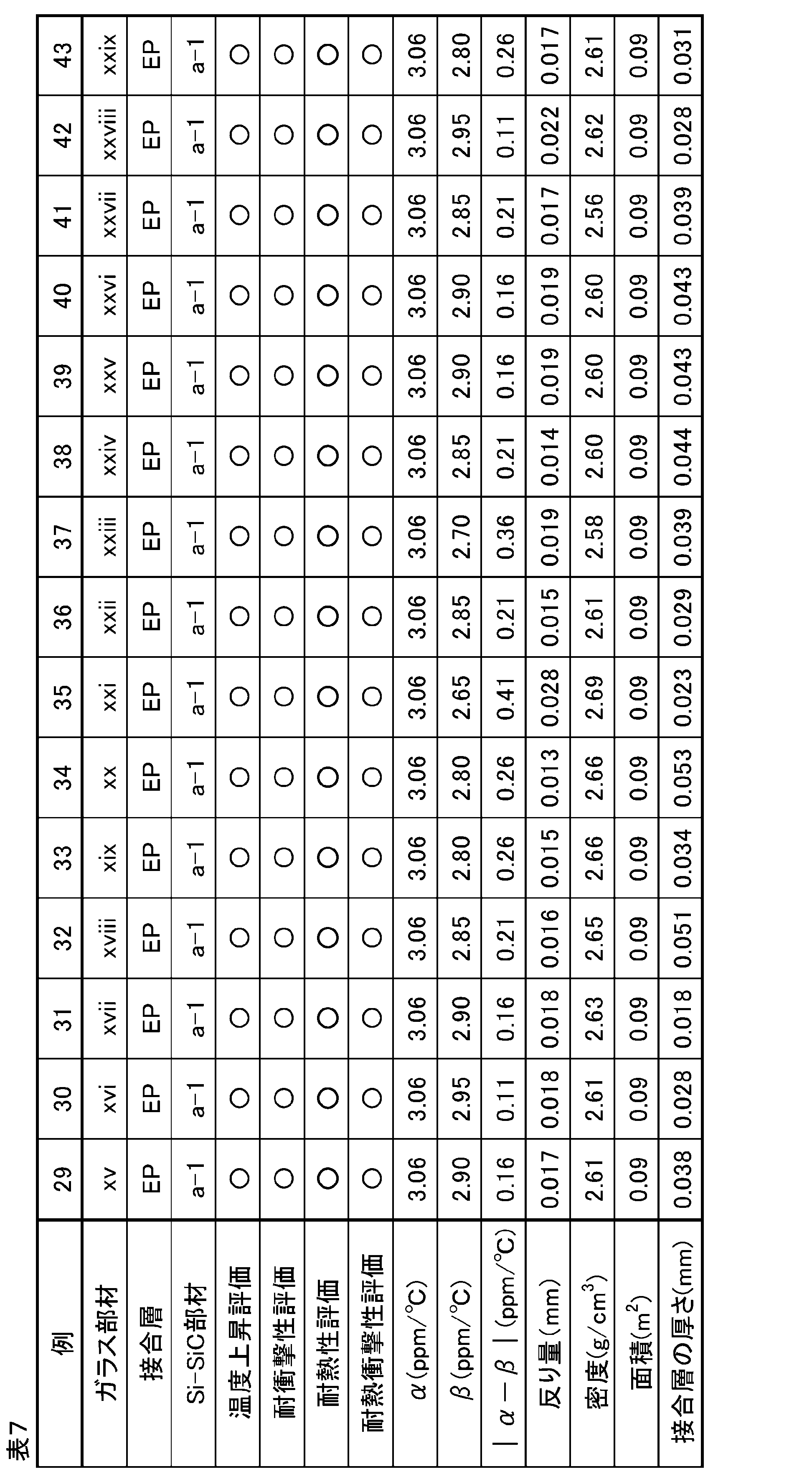
〔作製手順〕
各部材が表5~表7に記載の組み合わせになるように、例1~14、18~43のサンプル(積層部材)を以下のようにして作製した。また、例15~17のサンプルを準備した。
例1~5、7、9~13、20~24、26~43は実施例であり、例6、8、14~19、25は比較例である。
[Preparation procedure]
Samples (laminate members) of Examples 1 to 14 and 18 to 43 were prepared as follows so that the respective members were combined as shown in Tables 5 to 7. Samples of Examples 15 to 17 were also prepared.
Examples 1 to 5, 7, 9 to 13, 20 to 24, and 26 to 43 are working examples, and Examples 6, 8, 14 to 19, and 25 are comparative examples.
まず、SiC研磨紙を用いて、表1、表2に示すガラス部材の樹脂(接合層)と接触する側の表面を、Ra=0.2μmの面粗さに加工した。同様に、SiC研磨紙を用いて、表3に示すSi-SiC部材の樹脂(接合層)と接触する側の表面を、Ra=0.2μmの面粗さに加工した。
次に、表4に示す樹脂フィルムを、ガラス部材とSi-SiC部材との間に挟み込み、樹脂フィルムの軟化点+20度の温度に加熱し、2MPaの圧力をかけて5分間プレスすることで、ガラス部材とSi-SiC部材とを接合層を介して接合した。あるいは、表4に示す塗布タイプの接着剤をガラス部材に兵神社製ディスペンサーND型を用いて厚さ0.080mmで塗布し、さらにその上にSi-SiC部材を積層し、1.0MPaの圧力で加圧して120℃で4時間加熱し硬化させることで、ガラス部材とSi-SiC部材とを接合層を介して接合した。このようにして、例1~14、18~43のサンプル(積層部材)を得た。
First, the surfaces of the glass members shown in Tables 1 and 2 that come into contact with the resin (bonding layer) were processed to a surface roughness of Ra = 0.2 μm using SiC abrasive paper. Similarly, the surfaces of the Si-SiC members shown in Table 3 that come into contact with the resin (bonding layer) were processed to a surface roughness of Ra = 0.2 μm using SiC abrasive paper.
Next, the resin film shown in Table 4 was sandwiched between the glass member and the Si-SiC member, heated to a temperature of the softening point of the resin film +20 degrees, and pressed for 5 minutes with a pressure of 2 MPa to bond the glass member and the Si-SiC member via a bonding layer. Alternatively, the coating type adhesive shown in Table 4 was applied to the glass member with a thickness of 0.080 mm using a dispenser ND type made by Hyojinja, and the Si-SiC member was laminated on top of it, and the glass member and the Si-SiC member were bonded via a bonding layer by applying pressure at 1.0 MPa and heating and curing at 120 ° C for 4 hours. In this way, samples (laminate members) of Examples 1 to 14 and 18 to 43 were obtained.
〔積層部材の評価〕
各例のサンプルについて、以下の評価を行った。評価結果を上記表5~表7に示す。
[Evaluation of laminated members]
The samples of each example were subjected to the following evaluations. The evaluation results are shown in Tables 5 to 7 above.
(温度上昇評価)
各例のサンプルに、2kWの赤外線ランプ9個を用いて赤外線(850nm)を2分照射し、温度上昇の評価をした。
評価基準は、サンプルの最表面の温度が200℃を超える場合は〇、サンプルの最表面の温度が200℃を超えない場合は×とした。
積層部材である例1~14、18~43のサンプルは、ガラス部材側から赤外線を照射し、Si-SiC部材側の最表面温度で評価した。例15~17のサンプルは、赤外線照射側と反対側の最表面温度で評価した。
(Temperature rise evaluation)
The samples of each example were irradiated with infrared rays (850 nm) for 2 minutes using nine 2 kW infrared lamps, and the temperature rise was evaluated.
The evaluation criteria were as follows: ◯ when the temperature of the outermost surface of the sample exceeded 200°C; × when the temperature of the outermost surface of the sample did not exceed 200°C.
The laminated member samples of Examples 1 to 14 and 18 to 43 were irradiated with infrared rays from the glass member side and evaluated based on the outermost surface temperature of the Si-SiC member side. The laminated member samples of Examples 15 to 17 were evaluated based on the outermost surface temperature of the side opposite to the infrared ray irradiated side.
(耐衝撃性評価)
各例のサンプルに、533gの鋼球を落下させ、耐衝撃性の評価をした。耐衝撃性評価は、各例についてサンプル数3つ(n=3)で行った。サンプルの外周部には、厚さ3mm、幅15mm、硬さA50のゴム板製の支持枠を設け、上下から挟み込み固定した。鋼球はサンプルの中心から距離25mm以内の範囲に入るように落下させた。
評価基準は、落球高さ20cmで、サンプル数3つのうち2つ以上が割れた場合は×、サンプル数3つのうち1つが割れた場合は△、サンプル3つが割れなかった場合は〇として、△以上を合格とした。
積層部材である例1~14、18~43のサンプルは、Si-SiC部材側から鋼球を落下させた。なお、例17、25のサンプルについては、耐衝撃性を評価しなかった。
(Impact resistance evaluation)
A steel ball of 533 g was dropped onto the sample of each example to evaluate the impact resistance. The impact resistance evaluation was performed on three samples (n=3) for each example. A support frame made of a rubber plate having a thickness of 3 mm, a width of 15 mm, and a hardness of A50 was provided on the outer periphery of the sample, and the sample was sandwiched and fixed from above and below. The steel ball was dropped so as to be within a distance of 25 mm from the center of the sample.
The evaluation criteria were as follows: if two or more of the three samples broke at a falling height of 20 cm, it was given an X; if one of the three samples broke, it was given a △; if none of the three samples broke, it was given an O; and if the sample was △ or better, it was considered a pass.
The steel ball was dropped from the Si-SiC member side of the laminated member samples of Examples 1 to 14 and 18 to 43. Note that the impact resistance of Samples 17 and 25 was not evaluated.
(耐熱性評価)
各例のサンプルを230℃の温度で24時間加熱し、外観変化の目視評価をした。評価基準は、外観上の変化(変色、泡、異物の発生、接合層の滲みだしなど)が無かった場合は〇、外観上の変化が有った場合は×とした。なお、例25のサンプルについては、耐熱性を評価しなかった。
(Heat resistance evaluation)
The samples of each example were heated at a temperature of 230° C. for 24 hours, and visually evaluated for changes in appearance. The evaluation criteria were ◯ if there was no change in appearance (discoloration, bubbles, generation of foreign matter, bleeding of the bonding layer, etc.), and × if there was a change in appearance. The heat resistance of the sample of Example 25 was not evaluated.
(反り量)
各例のサンプルの反り量は、三鷹光機株式会社製の非接触三次元形状測定装置「NH-5Ns」を用いて、ISO25178-605に準拠してサンプル表面の三次元性状を測定し、サンプル表面の最大傾斜式平面度を求めることで測定した。
具体的には、精密定盤の上にサンプルを置き、レーザオートフォーカス顕微鏡を用いてサンプル上面の各点の高さを測定し、サンプル上面を平行な2つの平面で挟んだときにできる隙間の値、つまり、最大傾斜式平面度を反り量として求めた。
(Warpage amount)
The amount of warping of the samples in each example was measured using a non-contact three-dimensional shape measuring device "NH-5Ns" manufactured by Mitaka Koki Co., Ltd. in accordance with ISO 25178-605 to measure the three-dimensional properties of the sample surface and determine the maximum inclined flatness of the sample surface.
Specifically, a sample was placed on a precision surface plate, and the height of each point on the top surface of the sample was measured using a laser autofocus microscope. The value of the gap created when the top surface of the sample was sandwiched between two parallel flat surfaces, i.e., the maximum inclined flatness, was calculated as the amount of warping.
(密度)
各例のサンプルの質量を、株式会社ディジ・テック社製のデジタルメジャーで測定した体積で除して求めた。
(density)
The mass of each sample was divided by the volume measured using a digital measure manufactured by Digitec Corporation.
(面積)
各例のサンプルの最上面の面積(積層部材の場合はSi-SiC部材の露出している主表面、単部材の場合は一方の主表面)を、株式会社ディジ・テック社製のデジタルメジャーで測定した寸法から求めた。
(area)
The area of the top surface of each sample (the exposed main surface of the Si-SiC member in the case of a laminated member, or one of the main surfaces in the case of a single member) was determined from the dimensions measured using a digital tape measure manufactured by Digitec Corporation.
(接合層の厚さ)
例1~14、18~43のサンプルの接合層(樹脂)の厚さを、SEM断面観察により算出した。
(Thickness of bonding layer)
The thickness of the bonding layer (resin) of each of the samples of Examples 1 to 14 and 18 to 43 was calculated by observing the cross section using an SEM.
(耐熱衝撃性評価)
例1~14、18~43のサンプルと同じ組み合わせで、幅15mm、長さ100mmの積層部材を作製し、Si-SiC部材側を、ホットプレートを用いて加熱することでガラスとの間に温度差を与え、耐熱衝撃性の評価をした。具体的には、220℃にセットしたホットプレートを用いてSi-SiC部材表面を加熱し、ガラス部材側は冷却水を流し10℃に冷却した冷却板を用いて冷却し、温度差を与えた状態で1時間保持した。
評価基準は、目視にて接着層にクラックや白濁が見られた場合は×、変化が見られない場合は〇とした。なお、例15~17および例25のサンプルについては、耐熱衝撃性を評価しなかった。
(Thermal shock resistance evaluation)
A laminated member having a width of 15 mm and a length of 100 mm was prepared using the same combination as the samples of Examples 1 to 14 and 18 to 43, and the Si-SiC member side was heated using a hot plate to create a temperature difference between the glass and the laminated member, and the thermal shock resistance was evaluated. Specifically, the surface of the Si-SiC member was heated using a hot plate set at 220°C, and the glass member side was cooled using a cooling plate cooled to 10°C by flowing cooling water, and the temperature difference was maintained for 1 hour.
The evaluation criteria were as follows: if cracks or cloudiness were found in the adhesive layer by visual inspection, it was marked x; if no change was found, it was marked ◯. Note that the samples of Examples 15 to 17 and Example 25 were not evaluated for thermal shock resistance.
表5~表7の結果より、本発明の積層部材は、温度上昇速度が速く、耐衝撃性および耐熱衝撃性が高く、加熱部材として好適であることがわかった(例1~5、7、9~13、20~24、26~43)。 From the results in Tables 5 to 7, it was found that the laminated members of the present invention have a fast temperature rise rate, high impact resistance and thermal shock resistance, and are suitable as heating members (Examples 1 to 5, 7, 9 to 13, 20 to 24, 26 to 43).
一方、例6の積層部材は、Si-SiC部材の20~200℃における平均線膨張係数αが2.85ppm/℃未満と低く、耐熱衝撃性が低かった。
例8の積層部材は、Si-SiC部材の20~200℃における平均線膨張係数αが2.85ppm/℃未満と低く、耐衝撃性および耐熱衝撃性が低かった。
例14の積層部材は、温度上昇速度が速く、耐衝撃性および耐熱衝撃性が高いものの、反り量が大きかった。
例15~例17のサンプルは、温度上昇速度または耐衝撃性が低かった。
例18、19の積層部材は、Si-SiC部材の20~200℃における平均線膨張係数αが2.85ppm/℃未満と低く、耐熱衝撃性が低かった。
例23の積層部材は、耐衝撃性が低く、反り量が大きかった。
例25の積層部材は、温度上昇速度が低かった。
On the other hand, the laminated member of Example 6 had a low average linear expansion coefficient α of less than 2.85 ppm/° C. at 20 to 200° C. for the Si—SiC member, and thus had low thermal shock resistance.
In the laminated member of Example 8, the average linear expansion coefficient α of the Si-SiC member at 20 to 200° C. was low at less than 2.85 ppm/° C., and the impact resistance and thermal shock resistance were low.
The laminated member of Example 14 had a high temperature rise rate and high impact resistance and thermal shock resistance, but had a large amount of warping.
The samples of Examples 15 to 17 had low temperature rise rates or low impact resistance.
In the laminated members of Examples 18 and 19, the average linear expansion coefficient α of the Si-SiC members at 20 to 200° C. was low at less than 2.85 ppm/° C., and the thermal shock resistance was low.
The laminated member of Example 23 had low impact resistance and a large amount of warping.
The laminate of Example 25 had a slower rate of temperature rise.
以上、図面を参照しながら各種の実施の形態について説明したが、本発明はかかる例に限定されないことは言うまでもない。当業者であれば、特許請求の範囲に記載された範疇内において、各種の変更例又は修正例に想到し得ることは明らかであり、それらについても当然に本発明の技術的範囲に属するものと了解される。また、発明の趣旨を逸脱しない範囲において、上記実施の形態における各構成要素を任意に組み合わせてもよい。 Although various embodiments have been described above with reference to the drawings, it goes without saying that the present invention is not limited to such examples. It is clear that a person skilled in the art can come up with various modified or revised examples within the scope of the claims, and it is understood that these naturally fall within the technical scope of the present invention. Furthermore, the components in the above embodiments may be combined in any manner as long as it does not deviate from the spirit of the invention.
なお、本出願は、2021年1月20日出願の日本特許出願(特願2021-007287)に基づくものであり、その内容は本出願の中に参照として援用される。 This application is based on a Japanese patent application (Patent Application No. 2021-007287) filed on January 20, 2021, the contents of which are incorporated by reference into this application.
100 積層部材
101 ガラス部材
103 接合層
105 Si-SiC部材
100 Laminated member 101
Claims (18)
前記ガラス部材上に樹脂を含む接合層と、
前記接合層上にSi-SiC部材と、を有する積層部材であって、
前記ガラス部材が、酸化物基準のモル百分率表示で、55.0~85.0モル%のSiO2と、1.5~22.0モル%のAl2O3と、2.0~14.0モル%のB2O3と、0~5.0モル%のP2O5と、を含み、
前記SiO2、前記Al2O3、前記B2O3および前記P2O5の含有量の合計が、酸化物基準のモル百分率表示で、70.0~97.0%であり、
前記Si-SiC部材の20~200℃における平均線膨張係数αが、2.85~4.00ppm/℃であり、
前記ガラス部材の20~200℃における平均線膨張係数βが、1.50~5.00ppm/℃であり、
前記Si-SiC部材の20~200℃における平均線膨張係数αから前記ガラス部材の20~200℃における平均線膨張係数βを引いた値の絶対値|α-β|が2.00ppm/℃以下である、積層部材。 A glass member having an in-line transmittance of 80% or more at a wavelength of 850 nm;
a bonding layer including a resin on the glass member;
A laminated member having a Si-SiC member on the bonding layer,
The glass member contains, in terms of mole percentages on an oxide basis, 55.0 to 85.0 mol % of SiO 2 , 1.5 to 22.0 mol % of Al 2 O 3 , 2.0 to 14.0 mol % of B 2 O 3 , and 0 to 5.0 mol % of P 2 O 5 ;
the total content of the SiO 2 , the Al 2 O 3 , the B 2 O 3 and the P 2 O 5 is 70.0 to 97.0% in terms of mole percentage based on oxides;
The Si-SiC member has an average linear expansion coefficient α of 2.85 to 4.00 ppm/°C at 20 to 200°C,
The average linear expansion coefficient β of the glass member at 20 to 200° C. is 1.50 to 5.00 ppm/° C.;
The laminated member has an absolute value |α-β| obtained by subtracting the average linear expansion coefficient β of the glass member at 20 to 200° C. from the average linear expansion coefficient α of the Si-SiC member at 20 to 200° C., which is 2.00 ppm/° C. or less.
前記SiO2、前記Al2O3、前記B2O3および前記P2O5の含有量の合計が、酸化物基準のモル百分率表示で、80.0~90.0%である、請求項1に記載の積層部材。 The glass member contains, in terms of mole percentages on an oxide basis, 60.0 to 78.0 mol % of SiO 2 , 8.0 to 18.0 mol % of Al 2 O 3 , 2.0 to 11.0 mol % of B 2 O 3 , and 0 to 3.0 mol % of P 2 O 5 ;
2. The lamination member according to claim 1, wherein the total content of said SiO 2 , said Al 2 O 3 , said B 2 O 3 and said P 2 O 5 is 80.0 to 90.0% in terms of mole percentage based on oxides.
前記ガラス部材中のR2Oの含有量の合計が、酸化物基準のモル百分率表示で、0~15.0%である、請求項1または2に記載の積層部材。 the total content of RO and ZnO in the glass member is 2.0 to 25.0%, expressed in mole percentage on an oxide basis;
3. The laminate member according to claim 1, wherein the total content of R 2 O in the glass member is 0 to 15.0%, expressed as a mole percentage based on oxides.
前記Si-SiC部材の厚さが0.5~15mmである、請求項1~8のいずれか1項に記載の積層部材。 The glass member has a thickness of 2 to 40 mm;
The laminated member according to any one of claims 1 to 8, wherein the Si-SiC member has a thickness of 0.5 to 15 mm.
前記第2の接合層を介して前記Si-SiC部材と接合される第2のSi-SiC部材と、をさらに有する、請求項1~17のいずれか1項に記載の積層部材。 a second bonding layer provided on the Si-SiC member;
The laminated member according to any one of claims 1 to 17, further comprising a second Si-SiC member joined to the Si-SiC member via the second bonding layer.
Applications Claiming Priority (3)
| Application Number | Priority Date | Filing Date | Title |
|---|---|---|---|
| JP2021007287 | 2021-01-20 | ||
| JP2021007287 | 2021-01-20 | ||
| PCT/JP2022/001654 WO2022158457A1 (en) | 2021-01-20 | 2022-01-18 | Lamination member and glass composition |
Publications (2)
| Publication Number | Publication Date |
|---|---|
| JPWO2022158457A1 JPWO2022158457A1 (en) | 2022-07-28 |
| JP7589757B2 true JP7589757B2 (en) | 2024-11-26 |
Family
ID=82549420
Family Applications (1)
| Application Number | Title | Priority Date | Filing Date |
|---|---|---|---|
| JP2022576695A Active JP7589757B2 (en) | 2021-01-20 | 2022-01-18 | Laminated material |
Country Status (5)
| Country | Link |
|---|---|
| US (1) | US12410105B2 (en) |
| JP (1) | JP7589757B2 (en) |
| KR (1) | KR20230135064A (en) |
| CN (1) | CN116745251A (en) |
| WO (1) | WO2022158457A1 (en) |
Families Citing this family (2)
| Publication number | Priority date | Publication date | Assignee | Title |
|---|---|---|---|---|
| KR102905561B1 (en) * | 2019-07-25 | 2025-12-31 | 에이지씨 가부시키가이샤 | laminated member |
| JP7841427B2 (en) | 2020-06-10 | 2026-04-07 | Agc株式会社 | glass |
Citations (4)
| Publication number | Priority date | Publication date | Assignee | Title |
|---|---|---|---|---|
| JP2008199006A (en) | 2007-01-24 | 2008-08-28 | Asml Holding Nv | Wafer chuck and method for forming wafer chuck |
| WO2015087812A1 (en) | 2013-12-11 | 2015-06-18 | 旭硝子株式会社 | Cover glass for light emitting diode packages, sealed structure and light emitting device |
| JP2018203571A (en) | 2017-06-05 | 2018-12-27 | Agc株式会社 | Glass |
| WO2021251247A1 (en) | 2020-06-10 | 2021-12-16 | Agc株式会社 | Multilayer member |
Family Cites Families (24)
| Publication number | Priority date | Publication date | Assignee | Title |
|---|---|---|---|---|
| JPS6169116A (en) * | 1984-09-13 | 1986-04-09 | Toshiba Ceramics Co Ltd | Susceptor for continuous cvd coating on silicon wafer |
| US5200241A (en) * | 1989-05-18 | 1993-04-06 | General Electric Company | Metal-ceramic structure with intermediate high temperature reaction barrier layer |
| DE4429825C1 (en) * | 1994-08-23 | 1995-11-09 | Heraeus Quarzglas | Coated component made of quartz glass |
| JP3435410B2 (en) | 1996-05-09 | 2003-08-11 | 東京エレクトロン株式会社 | Low temperature test equipment and low temperature test method |
| JP4120897B2 (en) | 1997-09-25 | 2008-07-16 | 日本電気硝子株式会社 | Infrared transmitting glass ceramics |
| JP3960933B2 (en) * | 2003-03-18 | 2007-08-15 | 日本碍子株式会社 | High thermal conductive heat dissipation material and method for manufacturing the same |
| US7083694B2 (en) * | 2003-04-23 | 2006-08-01 | Integrated Materials, Inc. | Adhesive of a silicon and silica composite particularly useful for joining silicon parts |
| JP2005086711A (en) | 2003-09-10 | 2005-03-31 | Ngk Spark Plug Co Ltd | Method for manufacturing support resonator integrated dielectric resonator |
| JP5935304B2 (en) | 2010-12-27 | 2016-06-15 | 日本電気硝子株式会社 | Crystallized glass |
| JP2013197425A (en) * | 2012-03-22 | 2013-09-30 | Okamoto Machine Tool Works Ltd | Planarization grinding process of silicon carbide substrate |
| WO2013179881A1 (en) * | 2012-05-29 | 2013-12-05 | 旭硝子株式会社 | Glass laminate and method for manufacturing electronic device |
| JP6162428B2 (en) | 2013-02-27 | 2017-07-12 | 日本特殊陶業株式会社 | Support device |
| US11072144B2 (en) | 2013-11-26 | 2021-07-27 | Daikin Industries, Ltd. | Laminate |
| JPWO2016088778A1 (en) * | 2014-12-02 | 2017-09-14 | 旭硝子株式会社 | Glass plate and heater using the same |
| RU2591209C1 (en) * | 2015-04-06 | 2016-07-20 | Государственное научное учреждение "Институт порошковой металлургии" | Method of making light optical mirrors |
| WO2016190303A1 (en) * | 2015-05-28 | 2016-12-01 | 旭硝子株式会社 | Glass substrate and laminated substrate |
| JP6819613B2 (en) | 2015-12-28 | 2021-01-27 | Agc株式会社 | Manufacturing methods for glass substrates, laminated substrates, laminates, and semiconductor packages |
| JP6670153B2 (en) * | 2016-03-31 | 2020-03-18 | 日本碍子株式会社 | Heat storage material |
| CN109983350B (en) | 2016-11-29 | 2022-02-22 | 东京毅力科创株式会社 | Stages and test equipment for electronic devices |
| US11221358B2 (en) | 2017-03-21 | 2022-01-11 | Tokyo Electron Limited | Placement stand and electronic device inspecting apparatus |
| KR20260013303A (en) * | 2018-03-20 | 2026-01-27 | 에이지씨 가부시키가이샤 | Glass substrate, liquid crystal antenna and high-frequency device |
| KR102905559B1 (en) * | 2019-07-25 | 2025-12-31 | 에이지씨 가부시키가이샤 | laminated member |
| KR102905561B1 (en) * | 2019-07-25 | 2025-12-31 | 에이지씨 가부시키가이샤 | laminated member |
| JP7841427B2 (en) | 2020-06-10 | 2026-04-07 | Agc株式会社 | glass |
-
2022
- 2022-01-18 JP JP2022576695A patent/JP7589757B2/en active Active
- 2022-01-18 CN CN202280010574.XA patent/CN116745251A/en active Pending
- 2022-01-18 KR KR1020237024361A patent/KR20230135064A/en active Pending
- 2022-01-18 WO PCT/JP2022/001654 patent/WO2022158457A1/en not_active Ceased
-
2023
- 2023-07-18 US US18/353,977 patent/US12410105B2/en active Active
Patent Citations (4)
| Publication number | Priority date | Publication date | Assignee | Title |
|---|---|---|---|---|
| JP2008199006A (en) | 2007-01-24 | 2008-08-28 | Asml Holding Nv | Wafer chuck and method for forming wafer chuck |
| WO2015087812A1 (en) | 2013-12-11 | 2015-06-18 | 旭硝子株式会社 | Cover glass for light emitting diode packages, sealed structure and light emitting device |
| JP2018203571A (en) | 2017-06-05 | 2018-12-27 | Agc株式会社 | Glass |
| WO2021251247A1 (en) | 2020-06-10 | 2021-12-16 | Agc株式会社 | Multilayer member |
Also Published As
| Publication number | Publication date |
|---|---|
| WO2022158457A1 (en) | 2022-07-28 |
| TW202231471A (en) | 2022-08-16 |
| KR20230135064A (en) | 2023-09-22 |
| JPWO2022158457A1 (en) | 2022-07-28 |
| CN116745251A (en) | 2023-09-12 |
| US12410105B2 (en) | 2025-09-09 |
| TW202237395A (en) | 2022-10-01 |
| US20230357091A1 (en) | 2023-11-09 |
Similar Documents
| Publication | Publication Date | Title |
|---|---|---|
| JP7537434B2 (en) | Laminated material | |
| US12434456B2 (en) | Laminated member | |
| JP7287524B2 (en) | Alkali-free glass substrate, laminated substrate, and method for manufacturing glass substrate | |
| US12410105B2 (en) | Lamination member and glass composition | |
| JP7540440B2 (en) | Laminated material | |
| US12570571B2 (en) | Glass | |
| JP4790300B2 (en) | Glass | |
| TWI917537B (en) | Laminated components and glass assemblies | |
| TWI915315B (en) | Laminated components | |
| JP5169440B2 (en) | Method for producing glass substrate with electrode | |
| TW202608682A (en) | Laminated components | |
| WO2015199035A1 (en) | Radiation-shielding glass and laminated glass using same | |
| JP2006210328A (en) | Glass set for forming front substrate of plasma display panel | |
| WO2024219379A1 (en) | Glass | |
| TW202506588A (en) | Glass |
Legal Events
| Date | Code | Title | Description |
|---|---|---|---|
| A621 | Written request for application examination |
Free format text: JAPANESE INTERMEDIATE CODE: A621 Effective date: 20230718 |
|
| A131 | Notification of reasons for refusal |
Free format text: JAPANESE INTERMEDIATE CODE: A131 Effective date: 20240723 |
|
| A521 | Request for written amendment filed |
Free format text: JAPANESE INTERMEDIATE CODE: A523 Effective date: 20240920 |
|
| TRDD | Decision of grant or rejection written | ||
| A01 | Written decision to grant a patent or to grant a registration (utility model) |
Free format text: JAPANESE INTERMEDIATE CODE: A01 Effective date: 20241015 |
|
| A61 | First payment of annual fees (during grant procedure) |
Free format text: JAPANESE INTERMEDIATE CODE: A61 Effective date: 20241028 |
|
| R150 | Certificate of patent or registration of utility model |
Ref document number: 7589757 Country of ref document: JP Free format text: JAPANESE INTERMEDIATE CODE: R150 |