JP7588974B2 - Prosthetic implant including a frame for fixation to bone and related methods - Patents.com - Google Patents
Prosthetic implant including a frame for fixation to bone and related methods - Patents.com Download PDFInfo
- Publication number
- JP7588974B2 JP7588974B2 JP2020108729A JP2020108729A JP7588974B2 JP 7588974 B2 JP7588974 B2 JP 7588974B2 JP 2020108729 A JP2020108729 A JP 2020108729A JP 2020108729 A JP2020108729 A JP 2020108729A JP 7588974 B2 JP7588974 B2 JP 7588974B2
- Authority
- JP
- Japan
- Prior art keywords
- frame
- bone
- prosthetic
- glenoid
- component
- Prior art date
- Legal status (The legal status is an assumption and is not a legal conclusion. Google has not performed a legal analysis and makes no representation as to the accuracy of the status listed.)
- Active
Links
Images


Classifications
-
- A—HUMAN NECESSITIES
- A61—MEDICAL OR VETERINARY SCIENCE; HYGIENE
- A61F—FILTERS IMPLANTABLE INTO BLOOD VESSELS; PROSTHESES; DEVICES PROVIDING PATENCY TO, OR PREVENTING COLLAPSING OF, TUBULAR STRUCTURES OF THE BODY, e.g. STENTS; ORTHOPAEDIC, NURSING OR CONTRACEPTIVE DEVICES; FOMENTATION; TREATMENT OR PROTECTION OF EYES OR EARS; BANDAGES, DRESSINGS OR ABSORBENT PADS; FIRST-AID KITS
- A61F2/00—Filters implantable into blood vessels; Prostheses, i.e. artificial substitutes or replacements for parts of the body; Appliances for connecting them with the body; Devices providing patency to, or preventing collapsing of, tubular structures of the body, e.g. stents
- A61F2/02—Prostheses implantable into the body
- A61F2/30—Joints
- A61F2/30721—Accessories
- A61F2/30749—Fixation appliances for connecting prostheses to the body
-
- A—HUMAN NECESSITIES
- A61—MEDICAL OR VETERINARY SCIENCE; HYGIENE
- A61F—FILTERS IMPLANTABLE INTO BLOOD VESSELS; PROSTHESES; DEVICES PROVIDING PATENCY TO, OR PREVENTING COLLAPSING OF, TUBULAR STRUCTURES OF THE BODY, e.g. STENTS; ORTHOPAEDIC, NURSING OR CONTRACEPTIVE DEVICES; FOMENTATION; TREATMENT OR PROTECTION OF EYES OR EARS; BANDAGES, DRESSINGS OR ABSORBENT PADS; FIRST-AID KITS
- A61F2/00—Filters implantable into blood vessels; Prostheses, i.e. artificial substitutes or replacements for parts of the body; Appliances for connecting them with the body; Devices providing patency to, or preventing collapsing of, tubular structures of the body, e.g. stents
- A61F2/02—Prostheses implantable into the body
- A61F2/30—Joints
- A61F2/40—Joints for shoulders
- A61F2/4014—Humeral heads or necks; Connections of endoprosthetic heads or necks to endoprosthetic humeral shafts
-
- A—HUMAN NECESSITIES
- A61—MEDICAL OR VETERINARY SCIENCE; HYGIENE
- A61F—FILTERS IMPLANTABLE INTO BLOOD VESSELS; PROSTHESES; DEVICES PROVIDING PATENCY TO, OR PREVENTING COLLAPSING OF, TUBULAR STRUCTURES OF THE BODY, e.g. STENTS; ORTHOPAEDIC, NURSING OR CONTRACEPTIVE DEVICES; FOMENTATION; TREATMENT OR PROTECTION OF EYES OR EARS; BANDAGES, DRESSINGS OR ABSORBENT PADS; FIRST-AID KITS
- A61F2/00—Filters implantable into blood vessels; Prostheses, i.e. artificial substitutes or replacements for parts of the body; Appliances for connecting them with the body; Devices providing patency to, or preventing collapsing of, tubular structures of the body, e.g. stents
- A61F2/02—Prostheses implantable into the body
- A61F2/30—Joints
- A61F2/40—Joints for shoulders
- A61F2/4081—Glenoid components, e.g. cups
-
- A—HUMAN NECESSITIES
- A61—MEDICAL OR VETERINARY SCIENCE; HYGIENE
- A61F—FILTERS IMPLANTABLE INTO BLOOD VESSELS; PROSTHESES; DEVICES PROVIDING PATENCY TO, OR PREVENTING COLLAPSING OF, TUBULAR STRUCTURES OF THE BODY, e.g. STENTS; ORTHOPAEDIC, NURSING OR CONTRACEPTIVE DEVICES; FOMENTATION; TREATMENT OR PROTECTION OF EYES OR EARS; BANDAGES, DRESSINGS OR ABSORBENT PADS; FIRST-AID KITS
- A61F2/00—Filters implantable into blood vessels; Prostheses, i.e. artificial substitutes or replacements for parts of the body; Appliances for connecting them with the body; Devices providing patency to, or preventing collapsing of, tubular structures of the body, e.g. stents
- A61F2/02—Prostheses implantable into the body
- A61F2/30—Joints
- A61F2002/30001—Additional features of subject-matter classified in A61F2/28, A61F2/30 and subgroups thereof
- A61F2002/30108—Shapes
- A61F2002/30199—Three-dimensional shapes
- A61F2002/30224—Three-dimensional shapes cylindrical
-
- A—HUMAN NECESSITIES
- A61—MEDICAL OR VETERINARY SCIENCE; HYGIENE
- A61F—FILTERS IMPLANTABLE INTO BLOOD VESSELS; PROSTHESES; DEVICES PROVIDING PATENCY TO, OR PREVENTING COLLAPSING OF, TUBULAR STRUCTURES OF THE BODY, e.g. STENTS; ORTHOPAEDIC, NURSING OR CONTRACEPTIVE DEVICES; FOMENTATION; TREATMENT OR PROTECTION OF EYES OR EARS; BANDAGES, DRESSINGS OR ABSORBENT PADS; FIRST-AID KITS
- A61F2/00—Filters implantable into blood vessels; Prostheses, i.e. artificial substitutes or replacements for parts of the body; Appliances for connecting them with the body; Devices providing patency to, or preventing collapsing of, tubular structures of the body, e.g. stents
- A61F2/02—Prostheses implantable into the body
- A61F2/30—Joints
- A61F2002/30001—Additional features of subject-matter classified in A61F2/28, A61F2/30 and subgroups thereof
- A61F2002/30316—The prosthesis having different structural features at different locations within the same prosthesis; Connections between prosthetic parts; Special structural features of bone or joint prostheses not otherwise provided for
- A61F2002/30329—Connections or couplings between prosthetic parts, e.g. between modular parts; Connecting elements
- A61F2002/30331—Connections or couplings between prosthetic parts, e.g. between modular parts; Connecting elements made by longitudinally pushing a protrusion into a complementarily-shaped recess, e.g. held by friction fit
-
- A—HUMAN NECESSITIES
- A61—MEDICAL OR VETERINARY SCIENCE; HYGIENE
- A61F—FILTERS IMPLANTABLE INTO BLOOD VESSELS; PROSTHESES; DEVICES PROVIDING PATENCY TO, OR PREVENTING COLLAPSING OF, TUBULAR STRUCTURES OF THE BODY, e.g. STENTS; ORTHOPAEDIC, NURSING OR CONTRACEPTIVE DEVICES; FOMENTATION; TREATMENT OR PROTECTION OF EYES OR EARS; BANDAGES, DRESSINGS OR ABSORBENT PADS; FIRST-AID KITS
- A61F2/00—Filters implantable into blood vessels; Prostheses, i.e. artificial substitutes or replacements for parts of the body; Appliances for connecting them with the body; Devices providing patency to, or preventing collapsing of, tubular structures of the body, e.g. stents
- A61F2/02—Prostheses implantable into the body
- A61F2/30—Joints
- A61F2002/30001—Additional features of subject-matter classified in A61F2/28, A61F2/30 and subgroups thereof
- A61F2002/30316—The prosthesis having different structural features at different locations within the same prosthesis; Connections between prosthetic parts; Special structural features of bone or joint prostheses not otherwise provided for
- A61F2002/30329—Connections or couplings between prosthetic parts, e.g. between modular parts; Connecting elements
- A61F2002/30428—Connections or couplings between prosthetic parts, e.g. between modular parts; Connecting elements made by inserting a protrusion into a slot
-
- A—HUMAN NECESSITIES
- A61—MEDICAL OR VETERINARY SCIENCE; HYGIENE
- A61F—FILTERS IMPLANTABLE INTO BLOOD VESSELS; PROSTHESES; DEVICES PROVIDING PATENCY TO, OR PREVENTING COLLAPSING OF, TUBULAR STRUCTURES OF THE BODY, e.g. STENTS; ORTHOPAEDIC, NURSING OR CONTRACEPTIVE DEVICES; FOMENTATION; TREATMENT OR PROTECTION OF EYES OR EARS; BANDAGES, DRESSINGS OR ABSORBENT PADS; FIRST-AID KITS
- A61F2/00—Filters implantable into blood vessels; Prostheses, i.e. artificial substitutes or replacements for parts of the body; Appliances for connecting them with the body; Devices providing patency to, or preventing collapsing of, tubular structures of the body, e.g. stents
- A61F2/02—Prostheses implantable into the body
- A61F2/30—Joints
- A61F2002/30001—Additional features of subject-matter classified in A61F2/28, A61F2/30 and subgroups thereof
- A61F2002/30316—The prosthesis having different structural features at different locations within the same prosthesis; Connections between prosthetic parts; Special structural features of bone or joint prostheses not otherwise provided for
- A61F2002/30329—Connections or couplings between prosthetic parts, e.g. between modular parts; Connecting elements
- A61F2002/30476—Connections or couplings between prosthetic parts, e.g. between modular parts; Connecting elements locked by an additional locking mechanism
- A61F2002/305—Snap connection
-
- A—HUMAN NECESSITIES
- A61—MEDICAL OR VETERINARY SCIENCE; HYGIENE
- A61F—FILTERS IMPLANTABLE INTO BLOOD VESSELS; PROSTHESES; DEVICES PROVIDING PATENCY TO, OR PREVENTING COLLAPSING OF, TUBULAR STRUCTURES OF THE BODY, e.g. STENTS; ORTHOPAEDIC, NURSING OR CONTRACEPTIVE DEVICES; FOMENTATION; TREATMENT OR PROTECTION OF EYES OR EARS; BANDAGES, DRESSINGS OR ABSORBENT PADS; FIRST-AID KITS
- A61F2/00—Filters implantable into blood vessels; Prostheses, i.e. artificial substitutes or replacements for parts of the body; Appliances for connecting them with the body; Devices providing patency to, or preventing collapsing of, tubular structures of the body, e.g. stents
- A61F2/02—Prostheses implantable into the body
- A61F2/30—Joints
- A61F2002/30001—Additional features of subject-matter classified in A61F2/28, A61F2/30 and subgroups thereof
- A61F2002/30316—The prosthesis having different structural features at different locations within the same prosthesis; Connections between prosthetic parts; Special structural features of bone or joint prostheses not otherwise provided for
- A61F2002/30329—Connections or couplings between prosthetic parts, e.g. between modular parts; Connecting elements
- A61F2002/30476—Connections or couplings between prosthetic parts, e.g. between modular parts; Connecting elements locked by an additional locking mechanism
- A61F2002/30507—Connections or couplings between prosthetic parts, e.g. between modular parts; Connecting elements locked by an additional locking mechanism using a threaded locking member, e.g. a locking screw or a set screw
-
- A—HUMAN NECESSITIES
- A61—MEDICAL OR VETERINARY SCIENCE; HYGIENE
- A61F—FILTERS IMPLANTABLE INTO BLOOD VESSELS; PROSTHESES; DEVICES PROVIDING PATENCY TO, OR PREVENTING COLLAPSING OF, TUBULAR STRUCTURES OF THE BODY, e.g. STENTS; ORTHOPAEDIC, NURSING OR CONTRACEPTIVE DEVICES; FOMENTATION; TREATMENT OR PROTECTION OF EYES OR EARS; BANDAGES, DRESSINGS OR ABSORBENT PADS; FIRST-AID KITS
- A61F2/00—Filters implantable into blood vessels; Prostheses, i.e. artificial substitutes or replacements for parts of the body; Appliances for connecting them with the body; Devices providing patency to, or preventing collapsing of, tubular structures of the body, e.g. stents
- A61F2/02—Prostheses implantable into the body
- A61F2/30—Joints
- A61F2/30767—Special external or bone-contacting surface, e.g. coating for improving bone ingrowth
- A61F2/30771—Special external or bone-contacting surface, e.g. coating for improving bone ingrowth applied in original prostheses, e.g. holes or grooves
- A61F2002/30878—Special external or bone-contacting surface, e.g. coating for improving bone ingrowth applied in original prostheses, e.g. holes or grooves with non-sharp protrusions, for instance contacting the bone for anchoring, e.g. keels, pegs, pins, posts, shanks, stems, struts
- A61F2002/30879—Ribs
- A61F2002/30881—Circumferential ribs, flanges or fins
-
- A—HUMAN NECESSITIES
- A61—MEDICAL OR VETERINARY SCIENCE; HYGIENE
- A61F—FILTERS IMPLANTABLE INTO BLOOD VESSELS; PROSTHESES; DEVICES PROVIDING PATENCY TO, OR PREVENTING COLLAPSING OF, TUBULAR STRUCTURES OF THE BODY, e.g. STENTS; ORTHOPAEDIC, NURSING OR CONTRACEPTIVE DEVICES; FOMENTATION; TREATMENT OR PROTECTION OF EYES OR EARS; BANDAGES, DRESSINGS OR ABSORBENT PADS; FIRST-AID KITS
- A61F2/00—Filters implantable into blood vessels; Prostheses, i.e. artificial substitutes or replacements for parts of the body; Appliances for connecting them with the body; Devices providing patency to, or preventing collapsing of, tubular structures of the body, e.g. stents
- A61F2/02—Prostheses implantable into the body
- A61F2/30—Joints
- A61F2/30767—Special external or bone-contacting surface, e.g. coating for improving bone ingrowth
- A61F2/30771—Special external or bone-contacting surface, e.g. coating for improving bone ingrowth applied in original prostheses, e.g. holes or grooves
- A61F2002/30878—Special external or bone-contacting surface, e.g. coating for improving bone ingrowth applied in original prostheses, e.g. holes or grooves with non-sharp protrusions, for instance contacting the bone for anchoring, e.g. keels, pegs, pins, posts, shanks, stems, struts
- A61F2002/30891—Plurality of protrusions
-
- A—HUMAN NECESSITIES
- A61—MEDICAL OR VETERINARY SCIENCE; HYGIENE
- A61F—FILTERS IMPLANTABLE INTO BLOOD VESSELS; PROSTHESES; DEVICES PROVIDING PATENCY TO, OR PREVENTING COLLAPSING OF, TUBULAR STRUCTURES OF THE BODY, e.g. STENTS; ORTHOPAEDIC, NURSING OR CONTRACEPTIVE DEVICES; FOMENTATION; TREATMENT OR PROTECTION OF EYES OR EARS; BANDAGES, DRESSINGS OR ABSORBENT PADS; FIRST-AID KITS
- A61F2/00—Filters implantable into blood vessels; Prostheses, i.e. artificial substitutes or replacements for parts of the body; Appliances for connecting them with the body; Devices providing patency to, or preventing collapsing of, tubular structures of the body, e.g. stents
- A61F2/02—Prostheses implantable into the body
- A61F2/30—Joints
- A61F2/30767—Special external or bone-contacting surface, e.g. coating for improving bone ingrowth
- A61F2002/3092—Special external or bone-contacting surface, e.g. coating for improving bone ingrowth having an open-celled or open-pored structure
-
- A—HUMAN NECESSITIES
- A61—MEDICAL OR VETERINARY SCIENCE; HYGIENE
- A61F—FILTERS IMPLANTABLE INTO BLOOD VESSELS; PROSTHESES; DEVICES PROVIDING PATENCY TO, OR PREVENTING COLLAPSING OF, TUBULAR STRUCTURES OF THE BODY, e.g. STENTS; ORTHOPAEDIC, NURSING OR CONTRACEPTIVE DEVICES; FOMENTATION; TREATMENT OR PROTECTION OF EYES OR EARS; BANDAGES, DRESSINGS OR ABSORBENT PADS; FIRST-AID KITS
- A61F2/00—Filters implantable into blood vessels; Prostheses, i.e. artificial substitutes or replacements for parts of the body; Appliances for connecting them with the body; Devices providing patency to, or preventing collapsing of, tubular structures of the body, e.g. stents
- A61F2/02—Prostheses implantable into the body
- A61F2/30—Joints
- A61F2/40—Joints for shoulders
- A61F2/4081—Glenoid components, e.g. cups
- A61F2002/4085—Glenoid components, e.g. cups having a convex shape, e.g. hemispherical heads
-
- A—HUMAN NECESSITIES
- A61—MEDICAL OR VETERINARY SCIENCE; HYGIENE
- A61F—FILTERS IMPLANTABLE INTO BLOOD VESSELS; PROSTHESES; DEVICES PROVIDING PATENCY TO, OR PREVENTING COLLAPSING OF, TUBULAR STRUCTURES OF THE BODY, e.g. STENTS; ORTHOPAEDIC, NURSING OR CONTRACEPTIVE DEVICES; FOMENTATION; TREATMENT OR PROTECTION OF EYES OR EARS; BANDAGES, DRESSINGS OR ABSORBENT PADS; FIRST-AID KITS
- A61F2310/00—Prostheses classified in A61F2/28 or A61F2/30 - A61F2/44 being constructed from or coated with a particular material
- A61F2310/00389—The prosthesis being coated or covered with a particular material
- A61F2310/00395—Coating or prosthesis-covering structure made of metals or of alloys
- A61F2310/00407—Coating made of titanium or of Ti-based alloys
-
- A—HUMAN NECESSITIES
- A61—MEDICAL OR VETERINARY SCIENCE; HYGIENE
- A61F—FILTERS IMPLANTABLE INTO BLOOD VESSELS; PROSTHESES; DEVICES PROVIDING PATENCY TO, OR PREVENTING COLLAPSING OF, TUBULAR STRUCTURES OF THE BODY, e.g. STENTS; ORTHOPAEDIC, NURSING OR CONTRACEPTIVE DEVICES; FOMENTATION; TREATMENT OR PROTECTION OF EYES OR EARS; BANDAGES, DRESSINGS OR ABSORBENT PADS; FIRST-AID KITS
- A61F2310/00—Prostheses classified in A61F2/28 or A61F2/30 - A61F2/44 being constructed from or coated with a particular material
- A61F2310/00389—The prosthesis being coated or covered with a particular material
- A61F2310/00592—Coating or prosthesis-covering structure made of ceramics or of ceramic-like compounds
- A61F2310/00796—Coating or prosthesis-covering structure made of a phosphorus-containing compound, e.g. hydroxy(l)apatite
Landscapes
- Health & Medical Sciences (AREA)
- Orthopedic Medicine & Surgery (AREA)
- Cardiology (AREA)
- Oral & Maxillofacial Surgery (AREA)
- Transplantation (AREA)
- Engineering & Computer Science (AREA)
- Biomedical Technology (AREA)
- Heart & Thoracic Surgery (AREA)
- Vascular Medicine (AREA)
- Life Sciences & Earth Sciences (AREA)
- Animal Behavior & Ethology (AREA)
- General Health & Medical Sciences (AREA)
- Public Health (AREA)
- Veterinary Medicine (AREA)
- Prostheses (AREA)
- Surgical Instruments (AREA)
Description
本開示は、概してプロテーゼインプラントに関し、より具体的には、骨に固定するためのフレームを含むプロテーゼインプラントと、そのようなインプラントを患者に配設するための関連方法と、に関する。 The present disclosure relates generally to prosthetic implants, and more specifically to prosthetic implants including a frame for fixation to bone, and related methods for disposing such implants in a patient.
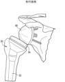
患者の一生の間には、例えば、疾患又は外傷の結果として、患者に全肩関節形成術を行う必要が生じる場合がある。図1Aに示すように、解剖学的全肩関節形成術では、上腕骨プロテーゼ10を使用して、患者の上腕骨の天然ヘッドを置換することができる。典型的には、上腕骨プロテーゼ10は、患者の上腕骨の髄内管内に埋め込まれる長尺状ポストコンポーネント12、及びポストコンポーネント12に固定される半球形状のプロテーゼヘッドコンポーネント14を含んでいる。加えて、肩甲骨の天然の関節窩表面は、解剖学的関節窩インプラント20を用いて、新しい表面に作り替えられるか、ないしは別の方法で置換され得る。解剖学的関節窩インプラント20は、典型的には、上腕骨プロテーゼ10のプロテーゼヘッドコンポーネント14がその上で関節運動する凹状の軸受表面24を含む。ペグ又はキール22は、インプラント20の遠位端から突出し得、患者の肩甲骨の関節窩内に接着され得る。
During a patient's lifetime, for example as a result of disease or trauma, a patient may need to undergo a total shoulder arthroplasty. As shown in FIG. 1A, in an anatomical total shoulder arthroplasty, a
解剖学的関節窩インプラントは、典型的にはポリエチレンで作製される。ポリエチレンは、比較的低い強度、硬度、及び剛性を有するが、比較的高い延性及び衝撃強度を有するプラスチック材料である。耐久性及び骨への固定を改善するために、いくつかのポリエチレンインプラントは、金属バックプレートで増強される。例えば、図1Bは、ポリエチレンコンポーネント32の遠位表面上に配設された金属バックプレート30を有する解剖学的関節窩インプラント20’を示す。そのような金属バックインプラントは、摩耗速度の増加、関節窩の緩み、応力遮蔽、過剰な関節窩骨喪失若しくは他の骨溶解、及び/又は金属バックプレートからのポリエチレンコンポーネントの分離などのいくつかの欠点を有し得る。これらの欠点のいくつかに対処する試みとして、ポリエチレンコンポーネントの厚さを調整することも行われてきた。しかしながら、ポリエチレンコンポーネントを薄くし過ぎると、インプラントの摩耗の加速化を招き得る。逆に、ポリエチレンコンポーネントを厚くし過ぎると、回旋腱板の過剰な張力及びポリエチレンコンポーネントに対する負荷の増加を招き得る。
Anatomical glenoid implants are typically made of polyethylene. Polyethylene is a plastic material that has relatively low strength, hardness, and stiffness, but relatively high ductility and impact strength. To improve durability and fixation to the bone, some polyethylene implants are augmented with a metal backplate. For example, FIG. 1B shows an anatomical glenoid implant 20' having a
いくつかの臨床的状況では、例えば、患者の天然の肩が重度の関節不安定性及び痛みへと悪化したときに、逆型全肩関節形成術を実施して肩の力学を変化させることが好ましい場合がある。逆型肩関節インプラントを使用して、健康な肩の解剖学的構造又は構造を逆転させることができる。例えば、図1Cに示すように、逆型全肩関節形成術では、上腕骨プロテーゼ50を使用して、患者の上腕骨の天然ヘッドを置換し得る。典型的には、上腕骨プロテーゼ50は、患者の上腕骨の髄内管内に埋め込まれる長尺状ポストコンポーネント52、及びポストコンポーネント52に固定される、上腕骨カップとして知られる凹状のプロテーゼヘッドコンポーネント54を含む。加えて、逆型関節窩インプラント、例えば、半球形状のグレノスフィア60を患者の肩甲骨の関節窩骨に固定することができる。かかる逆の構成は、大きく、かつより強い肩の筋肉の1つである患者の三角筋が腕を持ち上げることを可能とするものである。
In some clinical situations, for example, when a patient's natural shoulder deteriorates into severe joint instability and pain, it may be preferable to perform a reverse total shoulder arthroplasty to change the shoulder mechanics. A reverse shoulder implant can be used to reverse the anatomy or structure of a healthy shoulder. For example, as shown in FIG. 1C, in a reverse total shoulder arthroplasty, a
一部の患者では、解剖学的-逆型全肩関節形成術を実施して、以前に再建された肩関節を解剖学的構成から逆型構成に変換することができる。関節窩側では、以前に配設された解剖学的関節窩インプラント(例えば、20又は20’)を逆型関節窩インプラント(例えば、グレノスフィア60)と置換することができる。このような置換は、典型的には、対応のインプラントの独立した構成及びコンポーネントによる複雑かつ困難な処置を伴う。いくつかの臨床的状況において、骨喪失及び/又は関節窩骨の更なる劣化もまた、解剖学的-逆型変換の完全性を損ない得る処置中に生じ得る。 In some patients, an anatomical-reverse total shoulder arthroplasty can be performed to convert a previously reconstructed shoulder joint from an anatomical configuration to a reverse configuration. On the glenoid side, a previously placed anatomical glenoid implant (e.g., 20 or 20') can be replaced with a reverse glenoid implant (e.g., Glenosphere 60). Such replacement typically involves a complex and difficult procedure with separate configurations and components of the corresponding implant. In some clinical situations, bone loss and/or further deterioration of the glenoid bone can also occur during the procedure that can compromise the integrity of the anatomical-reverse conversion.
したがって、従来の金属バックインプラント(解剖学的肩関節再建処置に関して上述した装置及び方法など)の欠点を回避する方法で、インプラントを骨に固定するための改善されたプロテーゼインプラント及び関連方法が必要とされている。加えて、これらの複雑性を克服し得る効率的な方法で解剖学的-逆型全肩変換を実施するための、改善されたプロテーゼインプラント及び関連する方法が更に必要とされている。 Therefore, there is a need for improved prosthetic implants and related methods for securing the implant to bone in a manner that avoids the shortcomings of conventional metal back implants (such as the devices and methods described above with respect to anatomical shoulder reconstruction procedures). In addition, there is a further need for improved prosthetic implants and related methods for performing an anatomical-to-reverse total shoulder conversion in an efficient manner that can overcome these complexities.
本開示は、優れたインプラントと共に使用し得る、特に関節窩修復処置に使用するためのフレーム及びプロテーゼコンポーネントの組み合わせを提供するが、当業者は、本明細書で提供される、ないしは別の方法で本開示を考慮して導き出すことができるインプラントは、他の用途に、かつ、患者の身体の他の部分に使用され得、かかる患者はヒトに限定されない(すなわち、任意の動物)ことを理解されよう。本明細書に記載されるように、フレームとプロテーゼコンポーネントとの組み合わせは、プロテーゼコンポーネントがインプラント部位と直接接触することを可能にするために使用される。フレームは開口を画定し、プロテーゼコンポーネントの遠位向き表面は該開口を通過して、インプラント部位において骨と直接係合し得る。本明細書で提供されるフレーム及びプロテーゼコンポーネントは、プロテーゼコンポーネントが、フレームに固定されるか、ないしは別の方法で連結されると同時に、骨にも係合することを可能にする、様々な異なる構成を提供する。フレームは安定性を提供し、プロテーゼコンポーネントは、骨との所望の直接接触を提供する。多くの実施形態において、フレームは1つ以上の金属で作製することができ、プロテーゼは、1つ以上のプラスチック材料で作製することができる。プロテーゼコンポーネントをフレームと係合させるために提供される構成のいくつかの非限定的な例としては、骨アンカーポケット、固定ペグ、スナップ嵌めコネクタインターフェース及びコンポーネント、並びに取り外し可能なフレームアダプタ(例えば、Tバー)が挙げられる。本開示はまた、規則的な修復(例えば、全肩関節形成術)及び逆修復(例えば、逆型全肩関節形成術)の両方において、フレームなど、同じコンポーネントのいくつかを使用することができるという利益を可能にする。 While the present disclosure provides a combination of a frame and prosthetic components that may be used with a superior implant, particularly for use in glenoid repair procedures, those skilled in the art will understand that the implants provided herein or that may otherwise be derived in light of the present disclosure may be used for other applications and in other parts of a patient's body, such patients not being limited to humans (i.e., any animal). As described herein, the combination of the frame and prosthetic components is used to allow the prosthetic components to directly contact the implant site. The frame defines an opening, and the distally facing surface of the prosthetic component may pass through the opening to directly engage the bone at the implant site. The frames and prosthetic components provided herein provide a variety of different configurations that allow the prosthetic components to be secured or otherwise connected to the frame while also engaging the bone. The frame provides stability, and the prosthetic components provide the desired direct contact with the bone. In many embodiments, the frame can be made of one or more metals, and the prosthesis can be made of one or more plastic materials. Some non-limiting examples of configurations provided for engaging the prosthetic components with the frame include bone anchor pockets, fixation pegs, snap-fit connector interfaces and components, and removable frame adapters (e.g., T-bars). The present disclosure also allows for the benefit of being able to use some of the same components, such as frames, in both regular repairs (e.g., total shoulder arthroplasty) and reverse repairs (e.g., reverse total shoulder arthroplasty).
1つの例示的な実施形態では、プロテーゼインプラントは、プロテーゼコンポーネント及びフレームを含む。プロテーゼコンポーネントは、近位軸受表面及び遠位向き表面を有し、遠位向き表面は近位軸受表面と対向している。フレームは、骨内に固定されるように構成される。フレームは開口を画定し、プロテーゼコンポーネントの一部分は、該開口に通して配設されるように構成されており、フレームは、1つ以上の取り付けインターフェースを含む。1つ以上の取り付けインターフェースは、プロテーゼコンポーネントの遠位向き表面が、フレームの開口を通って延在して骨と直接接触するように、プロテーゼコンポーネントをフレームに連結するように構成される。 In one exemplary embodiment, the prosthetic implant includes a prosthetic component and a frame. The prosthetic component has a proximal bearing surface and a distal facing surface, the distal facing surface opposing the proximal bearing surface. The frame is configured to be secured within bone. The frame defines an opening, a portion of the prosthetic component is configured to be disposed through the opening, and the frame includes one or more attachment interfaces. The one or more attachment interfaces are configured to couple the prosthetic component to the frame such that a distal facing surface of the prosthetic component extends through the opening of the frame in direct contact with the bone.
フレームは、1つ以上の金属を含み得る。フレームはまた、環状形本体を含み得る。環状形本体は、実質的に平坦な近位表面と、実質的に凸形状の遠位表面と、を含み得る。環状形本体の内壁は、フレームの開口を画定し得る。 The frame may include one or more metals. The frame may also include an annular body. The annular body may include a substantially flat proximal surface and a substantially convex distal surface. An inner wall of the annular body may define an opening in the frame.
いくつかの実施形態では、フレームは、フレームを骨に固定するための1つ以上の骨アンカーポケットを含む。1つ以上の骨アンカーポケットのそれぞれは、骨アンカーを骨に挿入する際に通す貫通ボアを画定し得る。骨アンカーポケット(複数可)は、フレームの開口を通してアクセス可能であり得る。フレームは、フレームを骨に固定するための複数の固定ペグを含み得る。固定ベグ(beg)は、フレームから遠位方向に延在し得る。 In some embodiments, the frame includes one or more bone anchor pockets for securing the frame to the bone. Each of the one or more bone anchor pockets may define a through bore through which a bone anchor is inserted into the bone. The bone anchor pocket(s) may be accessible through an opening in the frame. The frame may include a plurality of fixation pegs for securing the frame to the bone. The fixation begs may extend distally from the frame.
フレームの1つ以上の取り付けインターフェースは、1つ以上のスナップ嵌めコネクタインターフェースを含み得る。いくつかのそのような実施形態では、プロテーゼコンポーネントは、フレームの1つ以上のスナップ嵌めコネクタインターフェース上にスナップ嵌めされるように構成され得る、1つ以上のスナップ嵌めコネクタをそれ自体で含む本体を含み得る。プロテーゼコンポーネントのスナップ嵌めコネクタ(複数可)がフレームのスナップ嵌めコネクタインターフェース(複数可)に取り付けられると、プロテーゼコンポーネントの遠位向き表面は、フレームの開口を通して骨と直接接触し得る。 The one or more attachment interfaces of the frame may include one or more snap-fit connector interfaces. In some such embodiments, the prosthetic component may include a body that itself includes one or more snap-fit connectors that may be configured to snap-fit onto the one or more snap-fit connector interfaces of the frame. When the snap-fit connector(s) of the prosthetic component are attached to the snap-fit connector interface(s) of the frame, the distally facing surface of the prosthetic component may be in direct contact with the bone through the opening in the frame.
1つ以上の金属を含むフレームに加えて、又はその代わりに、プロテーゼコンポーネントは、1つ以上のプラスチック材料を含み得る。プロテーゼコンポーネントは、プロテーゼコンポーネントの遠位向き表面から延在するポストを含み得る。ポストは、骨内に形成された空隙と係合するように構成され得る。いくつかの実施形態では、プロテーゼコンポーネントの遠位向き表面は、フレームの開口の断面プロファイルのネガを形成するように成形された断面プロファイルを含み得る。 In addition to or instead of a frame including one or more metals, the prosthetic component may include one or more plastic materials. The prosthetic component may include a post extending from a distally facing surface of the prosthetic component. The post may be configured to engage a void formed in the bone. In some embodiments, the distally facing surface of the prosthetic component may include a cross-sectional profile shaped to form a negative of the cross-sectional profile of the opening in the frame.
近位軸受表面及び遠位向き表面は、それぞれが凹形状、それぞれが凸形状、及び一方が凹形状で他方が凸形状を含む、様々な形状を有し得る。例えば、いくつかの例示的実施形態では、プロテーゼコンポーネントの遠位向き表面は凸形状を含み得、プロテーゼコンポーネントの近位軸受表面は凹形状を含み得る。 The proximal bearing surface and the distally facing surface may have a variety of shapes, including each being concave, each being convex, and one being concave and the other being convex. For example, in some exemplary embodiments, the distally facing surface of the prosthetic component may include a convex shape and the proximal bearing surface of the prosthetic component may include a concave shape.
フレームの1つ以上の取り付けインターフェースは、様々な構成を有し得る。例えば、場合によっては、フレームの1つ以上の取り付けインターフェースは、取り外し可能なフレームアダプタを含み得る。取り外し可能なフレームアダプタは、1つ以上のロックねじ留めを画定し得、取り外し可能なフレームアダプタは、フレームの対向する脚部の間で、開口を横切って延在するように構成され得る。いくつかのそのような実施形態では、フレームは、取り外し可能なフレームアダプタを誘導してフレームの対向する脚部の間でフレームの開口に位置合わせするように構成され得る、対向する凹部を画定する遠位表面を含み得る。プロテーゼコンポーネントは、取り外し可能なフレームアダプタの1つ以上のロック孔に対応し得る1つ以上の貫通孔を画定し得る。更に、プロテーゼコンポーネントは、ロックねじをプロテーゼコンポーネントの1つ以上の貫通孔に通して取り外し可能なフレームアダプタの1つ以上のロックねじ孔内に挿入することによって、フレームに連結されるように構成され得る。プロテーゼコンポーネントの遠位向き表面は、プロテーゼコンポーネントを取り外し可能なフレームアダプタと位置合わせするための凹部を画定し得る。いくつかの実施形態では、インプラントはプロテーゼヘッドを含み得る。ヘッドは、半球形状を有し得、プロテーゼコンポーネントの近位軸受表面に連結され得る。プロテーゼコンポーネントは、プロテーゼコンポーネントの遠位向き表面から延在するポストを含み得る。ポストは、骨内に形成された空隙と係合するように構成され得る。 The one or more mounting interfaces of the frame may have various configurations. For example, in some cases, the one or more mounting interfaces of the frame may include a removable frame adaptor. The removable frame adaptor may define one or more locking screw fasteners, and the removable frame adaptor may be configured to extend across an opening between opposing legs of the frame. In some such embodiments, the frame may include a distal surface defining opposing recesses that may be configured to guide the removable frame adaptor into alignment with the opening of the frame between opposing legs of the frame. The prosthetic component may define one or more through holes that may correspond to one or more locking holes of the removable frame adaptor. Further, the prosthetic component may be configured to be coupled to the frame by inserting a locking screw through one or more through holes of the prosthetic component and into one or more locking screw holes of the removable frame adaptor. The distally facing surface of the prosthetic component may define a recess for aligning the prosthetic component with the removable frame adaptor. In some embodiments, the implant may include a prosthetic head. The head may have a hemispherical shape and may be coupled to a proximal bearing surface of the prosthetic component. The prosthetic component may include a post extending from a distally facing surface of the prosthetic component. The post may be configured to engage a void formed in the bone.
更なる例として、フレームの1つ以上の取り付けインターフェースは、開口を通してアクセス可能であり得る1つ以上のロックねじポケットを含み得る。ロックねじポケット(複数可)は、1つ以上の対応するロックねじ孔を画定し得る。いくつかの実施形態では、ロックねじポケット(複数可)は、フレームの対向する脚部から開口内に突出する少なくとも2つのねじポケットを含み得る。プロテーゼコンポーネントは、1つ以上のロックねじポケットの1つ以上のロック孔に対応し得る1つ以上の貫通孔を画定し得る。更に、プロテーゼコンポーネントは、ロックねじをプロテーゼコンポーネントの1つ以上の貫通孔に通してロックねじポケットのロックねじ孔(複数可)内に挿入することによって、フレームに連結されるように構成され得る。プロテーゼコンポーネントの遠位向き表面は、1つ以上のガイドレールを含み得、ガイドレールは、プロテーゼコンポーネントをロックねじポケット(複数可)と位置合わせするためのものであり得る。いくつかの実施形態では、インプラントはプロテーゼヘッドを含み得る。ヘッドは、半球形状を有し得、プロテーゼコンポーネントの近位軸受表面に連結され得る。いくつかのこのような実施形態では、プロテーゼヘッドは、ロックねじをプロテーゼコンポーネントの1つ以上の貫通孔に通してロックねじポケット(複数可)のロックねじ孔(複数可)内に挿入する際に通す開口部を画定し得る。プロテーゼコンポーネントは、プロテーゼコンポーネントの遠位向き表面から延在するポストを含み得る。ポストは、骨内に形成された空隙と係合するように構成され得る。 As a further example, the one or more mounting interfaces of the frame may include one or more locking screw pockets that may be accessible through the opening. The locking screw pocket(s) may define one or more corresponding locking screw holes. In some embodiments, the locking screw pocket(s) may include at least two screw pockets that protrude into the opening from opposing legs of the frame. The prosthetic component may define one or more through holes that may correspond to one or more locking holes of the one or more locking screw pockets. Additionally, the prosthetic component may be configured to be coupled to the frame by inserting a locking screw through the one or more through holes of the prosthetic component and into the locking screw hole(s) of the locking screw pocket. The distally facing surface of the prosthetic component may include one or more guide rails, which may be for aligning the prosthetic component with the locking screw pocket(s). In some embodiments, the implant may include a prosthetic head. The head may have a hemispherical shape and may be coupled to a proximal bearing surface of the prosthetic component. In some such embodiments, the prosthetic head may define an opening through which a locking screw is inserted through one or more through holes in the prosthetic component and into the locking screw hole(s) of the locking screw pocket(s). The prosthetic component may include a post extending from a distally facing surface of the prosthetic component. The post may be configured to engage a void formed in the bone.
なお更なる例として、フレームの1つ以上の取り付けインターフェースは、複数の固定ペグを含み得る。固定ペグは、フレームから突出し得、フレームを骨に固定するためのものであり得る。このようなペグのうちの1つ以上は、それらの中に1つ以上のボアを画定し得る。プロテーゼコンポーネントは、固定ペグ(複数可)内に画定された1つ以上のボアに対応し得る1つ以上の孔を画定し得る。更に、プロテーゼコンポーネントは、ロックねじをプロテーゼコンポーネントの孔(複数可)に通して固定ペグ(複数可)内に画定された1つ以上のボアに挿入することによって、フレームに連結されるように構成され得る。いくつかのこのような実施形態では、プロテーゼコンポーネントの遠位向き表面は、フレームの開口の断面プロファイルのネガを形成するように成形された断面プロファイルを有し得る。ねじなしボアが、フレームの固定ペグの少なくとも1つに画定され得る。いくつかのこのような実施形態では、プロテーゼコンポーネントは、プロテーゼコンポーネントの遠位軸受表面から突出する回転防止ペグを含み得る。回転防止ペグは、ねじなしボアと嵌合するように構成され得る。いくつかの実施形態では、インプラントはプロテーゼヘッドを含み得る。ヘッドは、半球形状を有し得、プロテーゼコンポーネントの近位軸受表面に連結され得る。プロテーゼコンポーネントは、プロテーゼコンポーネントの遠位向き表面から延在するポストを含み得る。ポストは、骨内に形成された空隙と係合するように構成され得る。 As yet a further example, one or more mounting interfaces of the frame may include a plurality of fixation pegs. The fixation pegs may protrude from the frame and may be for fixing the frame to the bone. One or more of such pegs may define one or more bores therein. The prosthetic component may define one or more holes that may correspond to the one or more bores defined in the fixation peg(s). Additionally, the prosthetic component may be configured to be coupled to the frame by inserting a locking screw through the hole(s) of the prosthetic component and into the one or more bores defined in the fixation peg(s). In some such embodiments, the distally facing surface of the prosthetic component may have a cross-sectional profile shaped to form a negative of the cross-sectional profile of the opening in the frame. An unthreaded bore may be defined in at least one of the fixation pegs of the frame. In some such embodiments, the prosthetic component may include an anti-rotation peg protruding from a distal bearing surface of the prosthetic component. The anti-rotation peg may be configured to mate with the unthreaded bore. In some embodiments, the implant may include a prosthetic head. The head may have a hemispherical shape and may be coupled to a proximal bearing surface of the prosthetic component. The prosthetic component may include a post extending from a distally facing surface of the prosthetic component. The post may be configured to engage a void formed in the bone.
いくつかの実施形態では、インプラントは骨ねじを含み得る。骨ねじは、プロテーゼコンポーネントを骨に固定するために、プロテーゼコンポーネントのポスト内に配設されるように構成され得る。 In some embodiments, the implant may include a bone screw. The bone screw may be configured to be disposed within a post of the prosthetic component to secure the prosthetic component to bone.
1つ以上の取り付けインターフェースは、少なくとも2つの取り付けインターフェースを含み得る。いくつかのこのような実施形態では、第1の取り付けインターフェースは、プロテーゼ関節窩コンポーネントをフレームに取り付けるように構成され得、第2の取り付けインターフェースは、プロテーゼグレノスフィアコンポーネントをフレームに取り付けるように構成され得る。 The one or more attachment interfaces may include at least two attachment interfaces. In some such embodiments, a first attachment interface may be configured to attach a prosthetic glenoid component to the frame and a second attachment interface may be configured to attach a prosthetic glenosphere component to the frame.
プロテーゼインプラントを患者に挿入する1つの例示的な方法では、この方法は、フレームを骨に固定することと、プロテーゼコンポーネントをフレームに連結することと、を含む。フレームは開口を画定し、プロテーゼコンポーネントは、プロテーゼコンポーネントがフレームの開口を通して骨と直接接触するようにフレームに連結される。 In one exemplary method of inserting a prosthetic implant into a patient, the method includes securing a frame to bone and coupling a prosthetic component to the frame. The frame defines an opening, and the prosthetic component is coupled to the frame such that the prosthetic component is in direct contact with the bone through the opening in the frame.
この方法は、フレームからプロテーゼコンポーネントを取り外すことと、フレームが骨に固定されたままである間に、異なるプロテーゼコンポーネントをフレームに連結することと、を更に含み得る。異なるプロテーゼコンポーネントは、初期プロテーゼコンポーネントと同様の構成のコンポーネントであってもよく、又は異なる構成を有してもよい。 The method may further include removing the prosthetic component from the frame and coupling a different prosthetic component to the frame while the frame remains fixed to the bone. The different prosthetic component may be a component of similar configuration to the initial prosthetic component or may have a different configuration.
プロテーゼコンポーネントをフレームに連結する処置は、様々な方法で実施され得る。例えば、場合によっては、プロテーゼコンポーネントをフレームの1つ以上のスナップ嵌めコネクタインターフェースにスナップ嵌めするように、プロテーゼコンポーネントをフレームの開口内に押し込むことを伴い得る。あるいは、又は加えて、フレームの開口内に取り外し可能なフレームアダプタを挿入することと、フレームアダプタを操作して、フレームの対向する脚部の間に開口を横切って延在させることと、を含み得る。フレームアダプタは、1つ以上のねじ孔を画定し得、この方法は、プロテーゼコンポーネントの1つ以上の貫通孔を、フレームアダプタの1つ以上のねじ孔と位置合わせすることを更に伴い得る。ロックねじは、プロテーゼコンポーネントの1つ以上の貫通孔を通って、フレームアダプタの1つ以上のねじ孔に挿入され得る。 The procedure of coupling the prosthetic component to the frame may be performed in a variety of ways. For example, in some cases, it may involve forcing the prosthetic component into an opening in the frame so that the prosthetic component snaps into one or more snap-fit connector interfaces of the frame. Alternatively, or in addition, it may include inserting a removable frame adaptor into the opening in the frame and manipulating the frame adaptor to extend across the opening between opposing legs of the frame. The frame adaptor may define one or more screw holes, and the method may further involve aligning one or more through holes of the prosthetic component with one or more screw holes of the frame adaptor. Locking screws may be inserted through one or more through holes of the prosthetic component and into one or more screw holes of the frame adaptor.
更なる非限定的な例として、プロテーゼコンポーネントをフレームに連結することは、プロテーゼコンポーネントの1つ以上の貫通孔を、フレームから開口内に突出する1つ以上のロックねじポケット内に画定された1つ以上のねじ孔と位置合わせすることを含み得る。この方法は、ロックねじをプロテーゼコンポーネントのボア(複数可)に通して、フレームのロックねじポケット(複数可)の1つ以上のねじ孔に挿入することを更に含み得る。なお更なる非限定的な例として、プロテーゼコンポーネントをフレームに連結することは、プロテーゼコンポーネントの1つ以上の貫通孔を、フレームから遠位方向に突出する複数の固定ペグのうちの1つ以上に画定された1つ以上のボアと位置合わせすることを含み得る。この方法は、ロックねじをプロテーゼコンポーネントの貫通孔(複数可)に通して、固定ペグ(複数可)内に画定された1つ以上のボアのうちの1つ以上のボア内に挿入することを更に含み得る。 As a further non-limiting example, coupling the prosthetic component to the frame may include aligning one or more through holes of the prosthetic component with one or more screw holes defined in one or more locking screw pockets projecting from the frame into the opening. The method may further include inserting a locking screw through the bore(s) of the prosthetic component and into one or more screw holes of the locking screw pocket(s) of the frame. As a still further non-limiting example, coupling the prosthetic component to the frame may include aligning one or more through holes of the prosthetic component with one or more bores defined in one or more of a plurality of fixation pegs projecting distally from the frame. The method may further include inserting a locking screw through the through hole(s) of the prosthetic component and into one or more of the bores defined in the fixation peg(s).
いくつかの実施形態では、プロテーゼコンポーネントは、解剖学的関節窩コンポーネント及び逆型関節窩コンポーネントのうちの1つであり得る。フレームは、1つ以上の金属を含み得る。プロテーゼコンポーネントは、1つ以上のプラスチック材料を含み得る。 In some embodiments, the prosthetic component may be one of an anatomical glenoid component and a reverse glenoid component. The frame may include one or more metals. The prosthetic component may include one or more plastic materials.
本明細書に組み込まれ、本明細書の一部をなす添付の図面は、例示的な実施形態を例解したものであって、上に述べた一般的説明及び以下に述べる詳細な説明と共に、種々の実施形態の特徴を説明するものである。
以下に、本明細書で開示する装置及び方法の構造、機能、製造、及び使用の原理の全体的な理解が得られるように、特定の例示的な実施形態を説明する。これらの実施形態のうちの1つ又は2つ以上の実施例が、添付の図面に例示されている。当業者は、具体的に本明細書において説明され、添付の図面において例解される装置及び方法が、非限定的な例示的な実施形態であること、並びに本開示の範囲が、特許請求の範囲によってのみ定義されることを理解するであろう。1つの例示的な実施形態に関連して図示又は記載される特徴は、他の実施形態の特徴と組み合わせることができる。そのような修正及び変形は、本開示の範囲内に含まれるものとする。装置及びそのコンポーネントのサイズ及び形状は、様々な要因に依存し得るが、これらの要因としては、装置が使用される対象物(すなわち、患者)の解剖学的構造及び体質、装置が使用されるコンポーネントのサイズ及び形状、装置が使用される方法及び手技、並びに装置を操作する、及び/又は別様に関連する手技(複数可)を行う外科医の選好、が挙げられるが、これらに限定されない。例えば、少なくともいくつかの例示される実施形態において、プロテーゼインプラントのフレームの形状は実質的に楕円形であるが、当業者であれば、フレームは、他の要因の中でも、フレームが使用される他のコンポーネント(例えば、プロテーゼコンポーネント)、フレームが配設されている解剖学的構造(例えば、各種骨)、及び外科医の好みの形状、サイズ、及び構成に、少なくとも部分的に依存して、他の形状(例えば、円形、矩形)を有するように構成されてもよいことを認識するであろう。 Below, specific exemplary embodiments are described to provide a general understanding of the principles of the structure, function, manufacture, and use of the devices and methods disclosed herein. One or more examples of these embodiments are illustrated in the accompanying drawings. Those skilled in the art will appreciate that the devices and methods specifically described herein and illustrated in the accompanying drawings are non-limiting exemplary embodiments, and that the scope of the disclosure is defined only by the claims. Features shown or described in connection with one exemplary embodiment may be combined with features of other embodiments. Such modifications and variations are intended to be included within the scope of the present disclosure. The size and shape of the device and its components may depend on a variety of factors, including, but not limited to, the anatomy and constitution of the subject (i.e., the patient) on whom the device is used, the size and shape of the components on which the device is used, the method and procedure on which the device is used, and the preferences of the surgeon who will operate the device and/or perform the procedure(s) involved otherwise. For example, in at least some illustrated embodiments, the frame of the prosthetic implant is substantially oval in shape, although one skilled in the art will recognize that the frame may be configured to have other shapes (e.g., circular, rectangular) depending, at least in part, on the other components (e.g., prosthetic components) with which the frame is used, the anatomical structure (e.g., various bones) in which the frame is disposed, and the surgeon's preferred shape, size, and configuration, among other factors.
本開示では、実施形態の同様の名称のコンポーネントは、別途記載されない限り、概して、類似の機能及び/又は目的を有する。加えて、いくつかの用語が開示全体を通して互換的に使用される場合があるが、このことは当業者には理解されるであろう。更に、直線的又は円形の寸法が、開示された装置、及び方法の説明で使用される限りにおいて、このような寸法は、このような装置、及び方法と共に使用され得る形状のタイプを限定しようとするものではない。当業者は、かかる線形及び円形寸法に対する等価物を、任意の幾何学形状について容易に決定すること(例えば、当業者による、円形及び線形寸法のそれぞれについて容易に適合可能である幅及び直径の言及)ができることを認識するであろう。なお更に、開示されるプロテーゼ装置及びそのコンポーネントの、並びに/又はかかる装置の開示されるアセンブリ方法及び/若しくは埋め込み方法を行うための、方向、配向、及び/又は相対位置を説明するために、用語が本開示において使用される限りでは、かかる用語は、限定することを意図しない。例えば、当業者は、外科医又は他の操作者の観点に少なくとも部分的に依存して、方向、配向、及び/又は相対位置(例えば、近位、遠位、中間、横方向など)の用語を交換可能に使用することができることを認識するであろう。 In this disclosure, like-named components of the embodiments generally have similar functions and/or purposes unless otherwise stated. In addition, some terms may be used interchangeably throughout the disclosure, as would be understood by one of ordinary skill in the art. Furthermore, to the extent that linear or circular dimensions are used in describing the disclosed devices and methods, such dimensions are not intended to limit the types of shapes that may be used with such devices and methods. Those of ordinary skill in the art will recognize that equivalents to such linear and circular dimensions can be readily determined for any geometric shape (e.g., references to widths and diameters that are readily adaptable for circular and linear dimensions, respectively, by those of ordinary skill in the art). Still further, to the extent that terms are used in this disclosure to describe the directions, orientations, and/or relative positions of the disclosed prosthetic devices and their components, and/or for performing the disclosed assembly and/or implantation methods of such devices, such terms are not intended to be limiting. For example, those skilled in the art will recognize that terms of direction, orientation, and/or relative position (e.g., proximal, distal, medial, lateral, etc.) can be used interchangeably, depending at least in part on the perspective of a surgeon or other operator.
本開示は概して、肩関節の関節窩表面を増強又は置換するためのプロテーゼインプラントに関し、かかるインプラントの既存の設計に勝る改善を提供する。以下により詳細に論じられるように、プロテーゼインプラントの実施形態に提供されるものは、概して、骨に固定され、プロテーゼ関節窩コンポーネントをそれに取り付けることを可能にする、金属又は他の好適な材料で作製されたフレーム又はリムを含む。例えば、いくつかの実施形態では、ポリエチレン製の解剖学的関節窩コンポーネントは、フレーム上に取り外し可能にスナップ嵌めされるように構成され得る。その利点の中でも、フレームは、従来の固定技術と比較して、そのようなプラスチックコンポーネントの骨への固定を改善し得る。フレームはまた、他の利点の中でも、ポリエチレンコンポーネントの遠位表面が、フレームの開口を通したプラスチックと骨とが直接接触することを可能にし、応力遮蔽、関節窩の緩み、及び全体的な摩耗を低減し得る。 The present disclosure generally relates to a prosthetic implant for augmenting or replacing the glenoid surface of a shoulder joint, and provides improvements over existing designs of such implants. As discussed in more detail below, the embodiments of the prosthetic implant provided generally include a frame or rim made of metal or other suitable material that is secured to bone and allows for attachment of a prosthetic glenoid component thereto. For example, in some embodiments, a polyethylene anatomical glenoid component may be configured to be removably snap-fit onto the frame. Among its advantages, the frame may improve fixation of such plastic components to bone compared to conventional fixation techniques. The frame may also, among other advantages, allow the distal surface of the polyethylene component to have direct plastic-to-bone contact through openings in the frame, reducing stress shielding, glenoid loosening, and overall wear.
いくつかの実施形態では、プロテーゼインプラントのフレームは、フレームが骨に固定されたままである間に、あるタイプの関節窩コンポーネントから別のタイプに変換するため、2つ以上の取り付けインターフェースを含み得るか又は含むように適合され得る。例えば、以下により詳細に論じられるように、フレームは、第1の取り付けインターフェース(例えば、1組のスナップ嵌めコネクタインターフェース)から解剖学的関節窩コンポーネントを取り外し、逆型関節窩コンポーネントを第2の取り付けインターフェース(例えば、取り外し可能なフレームアダプタ、ロックねじポケット、及び/又は固定ペグ)に取り付けることによって、肩関節の解剖学的-逆型変換を容易にするために利用され得る。したがって、フレームは、肩関節インプラントが解剖学的構成から逆型構成に容易に変換されることを可能にし得る。 In some embodiments, the frame of the prosthetic implant may include or be adapted to include two or more attachment interfaces for converting from one type of glenoid component to another while the frame remains fixed to the bone. For example, as discussed in more detail below, the frame may be utilized to facilitate an anatomical-to-reverse conversion of the shoulder joint by removing an anatomical glenoid component from a first attachment interface (e.g., a set of snap-fit connector interfaces) and attaching a reverse glenoid component to a second attachment interface (e.g., a removable frame adapter, locking screw pockets, and/or fixation pegs). Thus, the frame may allow the shoulder joint implant to be easily converted from an anatomical configuration to a reverse configuration.
本明細書に開示される様々な実施形態は、プロテーゼコンポーネントを肩関節の関節窩側に固定するためのフレームを含むインプラントを伴うが、当業者は、本明細書で提供される開示がどのように、プロテーゼコンポーネント、例えば、プロテーゼヘッド又はカップを肩関節の上腕骨側に固定するためにフレームを利用するように適合され得るかを理解するであろう。当業者はまた、本開示の趣旨を逸脱から逸脱することなく、本明細書に提供されている開示がどのように、限定するものではないが、肘、くるぶし、股関節、及び/又は膝関節などの他の関節と関連付けられた装置及び手技と共に使用するように適合され得るかも理解するであろう。 While the various embodiments disclosed herein involve implants including a frame for securing a prosthetic component to the glenoid side of the shoulder joint, those skilled in the art will understand how the disclosure provided herein can be adapted to utilize a frame for securing a prosthetic component, such as a prosthetic head or cup, to the humeral side of the shoulder joint. Those skilled in the art will also understand how the disclosure provided herein can be adapted for use with devices and procedures associated with other joints, such as, but not limited to, the elbow, ankle, hip, and/or knee, without departing from the spirit of the present disclosure.
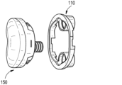
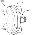
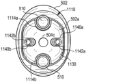
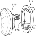
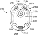
図2A~図2Dは、解剖学的肩関節インプラント100の1つの例示的な実施形態を示す。プロテーゼインプラント100は、フレーム110及び解剖学的関節窩コンポーネント150を含み得る。フレーム110は、骨に固定され得、関節窩コンポーネント150をフレームに取り付けるための複数の取り付けインターフェース120を含み得る。加えて、フレーム110は、開口130(図3Aを参照)を画定し得、関節窩コンポーネント150の遠位部分150dは、フレームに取り付けられたときに開口130を通して骨と直接接触し得る。以下により詳細に論じられるように、いくつかの実施形態では、フレーム110は、肩関節インプラント100が逆型肩関節インプラントに変換されることを可能にするように構成された取り外し可能なフレームアダプタで修正され得る。
2A-2D show one exemplary embodiment of an
例示される実施形態では、フレーム110は金属で作製される。フレームを製造するために使用され得る例示的な金属としては、非限定的な例として、チタン合金(例えば、Ti-6Al-4V)、タンタル、ステンレス鋼(例えば、316L)、コバルトクロム、これらの組み合わせ(又は他の材料との組み合わせ)、及び/又はそれらの任意の金属複合物/合金が挙げられる。しかしながら、当業者であれば、セラミック、ポリエチレン、ポリカーボネート、ポリエーテルエーテルケトン、又はこれらの材料を含む任意の組み合わせが、これらに限定されない他の材料を使用してフレームを製造し得ることを認識するであろう。解剖学的関節窩コンポーネント150は、プラスチック又はプラスチック材料で作製され得る。解剖学的関節窩コンポーネント150を製造するために使用され得る例示的なプラスチック材料としては、非限定的な例として、ポリエチレン、ポリエチレン類、ポリカーボネート、ポリエーテルエーテルケトン、及びこれらの組み合わせ(又は他の材料との組み合わせ)が挙げられ得る。しかしながら、当業者であれば、チタン合金(例えば、Ti-6Al-4V)、タンタル、ステンレス鋼(例えば、316L)、コバルトクロム、セラミックス、摩擦利点の硬度を上げるためのコーティング、又はこれらの材料を伴う任意の組み合わせを含む、解剖学的関節窩コンポーネントを製造するために他の材料が使用され得ることを認識するであろう。
In the illustrated embodiment, the
図3A~図3Dにより詳細に示されるように、フレーム110は、概ね環状形状の本体112を有し得る。例示される実施形態では、フレーム形状は実質的に楕円形である。しかしながら、当業者であれば、フレームは、他の要因の中でも、フレームが使用される他のコンポーネント(例えば、プロテーゼコンポーネント)、フレームが配設されている解剖学的構造(例えば、各種骨)、及び外科医の好みの形状、サイズ、及び構成に、少なくとも部分的に依存して、他の形状(例えば、円形、矩形)を有するように構成されてもよいことを認識するであろう。環状フレーム本体112は、解剖学的関節窩コンポーネント150の近位部分150pがフレーム110に取り付けられたときに当接し得るプラットフォームを提供する、実質的に平面の近位表面112pを有し得る。環状フレーム本体112の遠位表面112dは、患者の肩甲骨内の関節窩骨の実質的に凹状の表面と直接嵌合するように構成された実質的に凸状の形状を有し得る。当業者であれば、環状フレーム本体112の近位表面112p及び遠位表面112dは、例えば、他の要因の中でも、フレームに係合することが意図されたプロテーゼコンポーネント及び/又は骨の対向する表面に依存して、異なる形状又は表面トポロジーを有し得ることを認識するであろう。
As shown in more detail in FIGS. 3A-3D, the
フレーム110はまた、フレームを骨に固定するために使用される1つ以上の骨アンカーポケットを含み得る。例示される実施形態では、一対の骨アンカーポケット114a及び114b(集合的に114)は、環状フェーム本体112の実質的に対向する端部から遠位方向に突出するように構成されている。図示のように、骨アンカーポケット114aは、フレーム本体112の上端部112sに配設され得、骨アンカーポケット114bは、下端部112iに配設され得る。骨アンカーポケット114のそれぞれは、ねじ付き又はねじなしの貫通孔116a及び116b(集合的に116)を画定する、実質的に管状の形状を有し得る。多軸ねじ又は他の骨アンカー(図示せず)は、フレーム110を骨に固定するために、孔116に通して遠位方向に打ち込まれるか、ないしは別の方法で挿入され得る。図示のように、骨アンカーポケット114は、開口130を通してアクセス可能であり得る。一対の骨アンカーポケット114が示されているが、フレームは、フレームを骨に固定するために2つより多い又は少ない骨アンカーポケットを含み得る。あるいは、いくつかの実施形態では、骨アンカーポケットは、フレームの面内占有面積を増加させるという犠牲を払うものの、環状フレーム本体112の外辺部の外側でアクセスされ得る。
The
フレーム110の開口130は、環状フレーム本体112の内壁によって画定され得る。例示される実施形態では、開口は、概ね楕円形状の断面プロファイルを有し、例えば図3Aに示されるように、開口が開口内の深さに応じて複数の直径を有するような段差構成を更に含み得る。このような段差構成は、ねじなどを開口の内壁内に邪魔にならないように設置可能にすることを支援し得、段差構成は、ねじの遠位向き表面の形状に一致するように成形される。あるいは、いくつかの実施形態では、フレームは、限定するものではないが、矩形、多角形、円形、若しくはベスポーク形状、又はこれらの可能な形状の複数の開口を含む、様々な形状(複数可)を有する断面プロファイルを有する開口を画定し得る。フレーム開口130の寸法は、関節窩コンポーネント150と骨との間の接触表面積を直接最大化するように構成され得る。例えば、いくつかの実施形態では、フレーム開口130は、おおよそ、約20平方ミリメートル~約2400平方ミリメートルの範囲の断面積を有するように構成され得る。いくつかの実施形態では、フレーム開口部130の断面積は、おおよそ、約10パーセント~約99パーセントの範囲のフレーム110によって包囲された総断面積又は占有面積の割合と同等であり得る。いくつかの実施形態では、フレーム開口130の断面プロファイルは、おおよそ、約20ミリメートル~約60ミリメートルの範囲の最大長さ130L、及びおおよそ、約20ミリメートル~約40ミリメートルの範囲の最大幅130Wを有し得る。
The
例示される実施形態では、フレーム110は、解剖学的関節窩コンポーネント150をフレーム110に取り付けるための複数のスナップ嵌めコネクタインターフェース120a、120b、120c、120d、120e、及び120f(集合的に120)を含む。図3Dに示されるように、スナップ嵌めコネクタインターフェース120は、環状フレーム本体112の遠位表面112d内に画定され得る。スナップ嵌めコネクタインターフェース120は、スロット、溝、又は他の凹部として構成され得、時には、雌型連結コンポーネント、コネクタ、又はインターフェースと呼ばれ得る。図4A~図4Dに関連してより詳細に説明されるように、スナップ嵌めコネクタインターフェース120は、解剖学的関節窩コンポーネント150の対応するスナップ嵌めコネクタが、一緒に押圧されたときにフレーム110と結合するか、ないしは別の方法で係合することを可能にするように構成され得る。
In the illustrated embodiment, the
フレーム110のスナップ嵌めコネクタインターフェース120は、環状本体の遠位表面112dの周りに均等に分散され得る。例えば、例示される実施形態では、2つのスナップ嵌めコネクタインターフェース120a及び120bは、骨アンカーポケット114aに隣接する環状フレーム本体112の上端部112sに画定され、2つのスナップ嵌めコネクタインターフェース120c及び120dは、骨アンカーポケット114bに隣接する環状フレーム本体の下端部112iに画定され、2つのスナップ嵌めコネクタインターフェース120e及び120fは、上端部と下端部との間の環状フレーム本体の対向する脚部上に画定される。図には、6つのスナップ嵌めコネクタインターフェース120を含むものとしてフレーム110が示されているが、フレームは、環状本体112の遠位表面112d内の様々な位置に画定された、6つより多い又は少ないスナップ嵌めコネクタインターフェース(例えば、1、2、3、4、5、7、8、9、又は10など)を含み得る。あるいは、又は加えて、いくつかの実施形態では、スナップ嵌めコネクタインターフェース120のうちの1つ以上は、環状本体112の近位表面112p内に画定されてもよい。
The snap-fit connector interfaces 120 of the
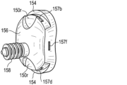
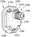
図4A~図4Dに示されるように、解剖学的関節窩コンポーネント150は、近位部分150p及び遠位部分150dを含む概ね円盤状の本体を有し得る。近位部分150pは、上腕骨プロテーゼ(例えば、図1Aの10)のプロテーゼヘッド(例えば、図1Aの14)が関節運動し得る近位軸受表面152を有し得る。近位軸受表面152は、健康な関節窩骨の凹部を実質的に模倣する、実質的に凹状の形状を有し得る。近位部分150pは、関節窩コンポーネント150の近位部分150pと遠位部分150dとの間のインターフェースに、遠位向き隆起部154を画定し得る。隆起部154は、関節窩コンポーネント150がフレーム100に取り付けられたときにフレーム110の近位表面112pに当接する停止部として機能し得る。例示される実施形態では、隆起部154は、コンポーネント150の上端部150s及び下端部150iにおいて外向きに突出している。
As shown in FIGS. 4A-4D, the anatomical
解剖学的関節窩コンポーネント150の遠位部分150dは、フレーム110の開口130内に挿入するように構成されたベスポーク形状を有し得る。例えば、例示される実施形態では、遠位部分150dのベスポーク形状は、フレーム開口130の断面プロファイルのネガを概ね形成するように構成された断面プロファイルを有する。遠位部分150はまた、骨アンカーポケット114を取り囲む(又は少なくとも部分的に取り囲む)ように構成された凹部(又は切欠部分)150rを画定し得、そのようにして、関節窩コンポーネント150のフレーム110への取り付け中にポケットが干渉することを防止する。遠位部分150dは、患者の肩甲骨内の関節窩骨の実質的に凹状の表面と直接嵌合するように構成された概ね凸形状の遠位軸受表面156を有し得、そのようにして、関節窩コンポーネント150と関節窩骨との間の接触表面積を最大化し得る。
The
当業者であれば、解剖学的関節窩コンポーネント150の遠位軸受表面156は、例えば、標的骨の対向する表面トポロジーに応じて、異なる形状又は表面トポロジーを有し得ることを認識するであろう。いくつかの実施形態では、関節窩コンポーネント150の遠位部分150dは、遠位軸受表面156から外向きに突出する骨係合ポスト158を含み得る。以下により詳細に記載されるように、骨係合ポスト158は、関節窩骨に開けられる孔又は空隙と係合するように構成され得る。1本の骨係合ポスト158が図に示されているが、1本より多い又は少ない骨係合ポストが、解剖学的関節窩コンポーネント150の遠位軸受表面156から突出するように構成され得る(例えば、0本、2本、3本、又は4本以上のポスト)。
Those skilled in the art will recognize that the
上述のように、フレーム110は、解剖学的関節窩コンポーネント150をフレームに取り付けるための複数のスナップ嵌めコネクタインターフェース120を含み得る。図4C及び図4Dを参照すると、解剖学的関節窩コンポーネント150は、フレーム110の対応するスナップ嵌めコネクタインターフェース120a、120b、120c、120d、120e、及び120f(集合的に120)と結合するか、ないしは別の方法で係合するように構成された複数のスナップ嵌めコネクタ157a、157b、157c、157d、157e、及び157f(集合的に157)を含み得る。例示される実施形態では、スナップ嵌めコネクタ157のそれぞれは、プロテーゼコンポーネント150の遠位部分150dから横方向に突出し、スナップ嵌めコネクタインターフェース120の位置でフレーム110内にスナップ嵌めされるように構成された舌部又は突出部であり得る。コネクタ157は、時には、雄型連結コンポーネント、コネクタ、又はインターフェースと呼ばれ得る。当業者であれば、スナップ嵌めコネクタ157は、解剖学的関節窩コンポーネント150がフレーム110上に押圧されたときにスナップ嵌めコネクタインターフェース120を係合するための代替の形状及び/又は構成を有し得ることを認識するであろう。非限定的な例として、雄型接続及び雌型接続は、2つのコンポーネント110、150の間で反転され得る。
As mentioned above, the
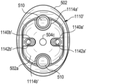
図5A~図5Cは、患者の肩甲骨内に解剖学的肩関節インプラント100を配設する方法の例示的な実施形態の概略図である。例示される実施形態では、解剖学的肩関節インプラント100は、解剖学的肩関節全置換術の一部として埋め込まれ得、それにより、インプラント100は、患者の肩甲骨の関節窩骨に固定されて、上腕骨プロテーゼのプロテーゼヘッド(例えば、図1Aの14)の対応する凹状の軸受表面を提供する。例示される方法は上述のインプラント100を使用するが、インプラント100に関連付けられる、ないしは別の方法でインプラント100と共に使用されるコンポーネントの少なくともいくつかは容易に視認できない場合がある。本明細書に提供される本開示、及びそれらの関連する図を考慮して、当業者は、インプラント100の種々のコンポーネントが、どのように、患者の解剖学的構造の種々の部分に、並びに/又は図5A~図5Cに関して開示される処置と共に使用されるインプラント100及び関連する工具(複数可)のコンポーネントに係合するのかを理解するであろう。
5A-5C are schematic diagrams of an exemplary embodiment of a method for disposing an
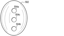
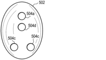
図5Aを参照すると、患者の肩甲骨の関節窩骨502は、インプラント100を装着するためのほぼ滑らかな凹面を有するように調整され得る。当業者であれば、リーマー(図示せず)又は他の工具(複数可)を使用して、フレーム110及び解剖学的関節窩コンポーネント150の凸形状の遠位表面と嵌合するように、関節窩骨502の凹面を調製し得ることを認識するであろう。加えて、インプラント100の装着用に1つ以上の孔又は空隙504a、504b、504cを関節窩骨502に穿孔することができる(図示のように、3つ)。例えば、孔504a及び504bは、フレーム110の管形状の骨アンカーポケット114a及び114bを受容するように構成され得、孔504cは、解剖学的関節窩コンポーネント150の骨係合ポスト158を受容するように構成され得る。いくつかの実施形態では、当業者であれば、他の工具(複数可)の中でも、ガイドピン及び/又はガイドプレート(図示せず)と位置合わせされた停止ドリルを使用して穿孔し得ることを認識するであろう。
5A, the
図5Bを参照すると、フレーム110は関節窩骨502に固定され得る。例えば、例示される実施形態では、フレーム110は、骨アンカーポケット114a及び114bを穿孔504a及び504b内に挿入することによって骨に固定され得る。その後、多軸骨ねじ510又は他の骨アンカーは、それぞれのポケットを通って関節窩骨502内へと遠位方向に打ち込まれるか、ないしは別の方法で挿入され得る。いくつかの実施形態では、ねじ回し(図示せず)を使用して、骨ねじ510を関節窩骨に打ち込むことができる。フレーム110が骨に固定されると、フレーム開口130は、孔504cを含む関節窩骨502の凹形状部分502aを露出させ得る。
5B, the
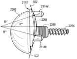
図5Cを参照すると、解剖学的関節窩コンポーネント150は、関節窩コンポーネントの遠位部分150dがフレーム開口130を通して関節窩骨502aと直接接触するように、フレーム110に取り付けられ得る。例えば、図示のように、関節窩コンポーネントの凸形状の遠位表面156及びポスト158は、フレーム開口130を通して関節窩骨502aと直接接触し得る。関節窩コンポーネント150の凸形状の遠位表面156及びフレーム110の凸形状の遠位表面112dを、同じ又は実質的に同じ曲率半径Rを有するように構成することによって、直接コンポーネントと骨との接触表面積を最大化させることができる。
5C, the anatomical
いくつかの実施形態では、解剖学的関節窩コンポーネント150は、ポスト158を開口130に通して穿孔504c内に挿入し、該コンポーネントを開口130に通して、フレームにスナップ嵌めされるまで遠位方向に押すことによって、フレーム110に取り付けられ得る。例えば、解剖学的関節窩コンポーネント150は、コンポーネント(不可視)のスナップ嵌めコネクタ157がフレーム110のスナップ嵌めコネクタインターフェース120(不可視)と結合するか、ないしは別の方法で係合するとき、フレーム上にスナップ嵌めされ得る。ポスト158は、穿孔504cの直径に対して僅かにオーバーサイズであり得、プレス嵌合を可能にし得る。
In some embodiments, the anatomical
上述のように、いくつかの臨床的状況では、患者の肩関節の解剖学的構造又は構造を反転させることを伴う逆型全肩関節形成術を実施することが必要である場合がある。例えば、関節窩側では、半球形状のグレノスフィア(すなわち、球窩関節の「球」)を含む逆型関節窩インプラントが、患者の肩甲骨の関節窩骨に固定され得る。一部の患者では、以前に配設された解剖学的関節窩インプラントを逆型関節窩インプラントに置換するために、解剖学的-逆型変換が必要である場合がある。このような置換は、典型的には、対応のインプラントの独立した構成及び構成及びコンポーネントによる複雑かつ困難な処置を伴う。したがって、図6A~図6Dに関してより詳細に記載されるように、解剖学的肩関節インプラント(例えば、100)の以前に固定されたフレーム(例えば、110)を再使用して、かかる複雑さを回避し得る方法で解剖学的-逆型変換を容易にするように構成され得る、逆型肩関節インプラントが本明細書に提供される。 As mentioned above, in some clinical situations, it may be necessary to perform a reverse total shoulder arthroplasty, which involves reversing the anatomy or structure of the patient's shoulder joint. For example, on the glenoid side, a reverse glenoid implant including a hemispherical glenosphere (i.e., the "ball" of the ball-and-socket joint) may be fixed to the glenoid bone of the patient's scapula. In some patients, an anatomical-to-reverse conversion may be required to replace a previously placed anatomical glenoid implant with a reverse glenoid implant. Such a replacement typically involves a complex and difficult procedure with separate configurations and components of the corresponding implant. Thus, as described in more detail with respect to FIGS. 6A-6D, a reverse shoulder implant is provided herein that may be configured to reuse a previously fixed frame (e.g., 110) of an anatomical shoulder implant (e.g., 100) to facilitate an anatomical-to-reverse conversion in a manner that may avoid such complications.
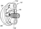
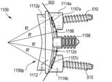
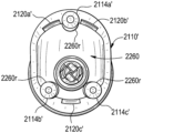
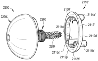
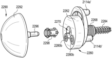
図6A~図6Dは、逆型肩関節インプラント200の例示的な実施形態を示す。プロテーゼインプラント200は、フレーム110’、フレームアダプタ140、及び逆型関節窩コンポーネント250を含み得る。例示される実施形態では、フレーム110’は、環状形状の本体112’、骨アンカーポケット114a’及び114b’(集合的に114’)、並びに環状フレーム本体内に画定されたスナップ嵌めコネクタインターフェース120a’、120b’、120c’、120d’、120e’、及び120f’(集合的に120’)を含む。以下に記載されるか、又は当業者によって容易に理解されることを除いて、フレーム110’は、上述のフレーム110と同じ又は実質的に同じである。ゆえに、フレーム110’の構造及び機能の詳細な説明は、簡潔にするためにここでは省略する。
6A-6D show an exemplary embodiment of a
いくつかの実施形態では、フレームアダプタ140は、フレーム110’の対向する脚部の間で、フレーム開口130’を横切って実質的に水平に延在するように構成された取り外し可能な取り付けバーであり得る。例えば、例示される実施形態では、フレームアダプタ140は、フレームアダプタ140の末端部140a及び140bが環状フレーム本体112’の遠位表面112d’内に画定された対応する凹部120e’及び120f’内に受容されるように、フレーム開口130’にわたって延在するように構成されている。いくつかの実施形態では、凹部120e’及び120f’は、図3A~図3Dに関連して上述したスナップ嵌めコネクタインターフェース120e及び120fと同じであり得る。
In some embodiments, the
フレームアダプタ140は、逆型関節窩コンポーネント250をフレーム110’に取り付けるための対応するロックねじ(図示せず)を受容するように構成された一対のロックねじ孔142a及び142b(集合的に142)を画定し得る。2つのロックねじ孔142が図に示されているが、フレームアダプタ140内には2つより多い又は少ないロックねじ孔(例えば、1、3、4、5、又は6つ以上のロックねじボア)が画定され得る。いくつかの実施形態では、フレームアダプタ140は、フレームアダプタが位置合わせの鍵として機能することを可能にする断面形状を有し得る。例えば、例示される実施形態では、フレームアダプタ140は、逆型関節窩コンポーネント250内に画定された対応するT字形状凹部(例えば、図7Bの262r)内に受容されるように構成されたT字形状断面を有する。
The
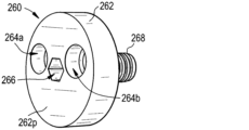
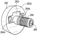
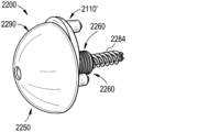
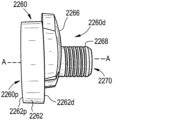
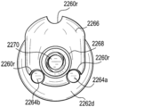
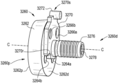
逆型関節窩コンポーネント250は、ベースプレート260と、ベースプレートに連結された半球形状のプロテーゼヘッド290と、を含み得る。当業者であれば、本開示を考慮すると、逆型関節窩コンポーネント250が本明細書に提供されるようなプロテーゼコンポーネントであり、ベースプレート260は、プロテーゼコンポーネントの遠位向き表面の一部であるか、又はそこに連結されており、半球形状のプロテーゼヘッド290は、プロテーゼコンポーネントの近位軸受表面の一部であるか、又はそれに連結されていることを理解するであろう。図7A及び図7Bに示されるように、本明細書で「関節窩受け部」と呼ばれる場合があるベースプレート260は、概ね円盤形状のプラットフォーム262と、その遠位表面262dから外向きに延在する円筒形状のポスト268と、を含み得る。1つ以上の貫通孔は、関節窩受け部プラットフォーム262の近位表面262p及び遠位表面262dを通って延在するように画定され得る。例示される実施形態では、一対の貫通孔264a及び264b(集合的に264)は、関節窩受け部プラットフォーム262内に画定され、フレームアダプタ140の対応するロックねじ孔142a及び142bと位置合わせするように構成されている。2つの貫通孔264が図に示されているが、例えば、フレームアダプタ内に画定されたロックねじ孔の数に応じて、2つより多い又は少ない貫通孔が関節窩受け部プラットフォーム262内に画定され得る(例えば、1、3、4、5、又は6つ以上の貫通孔)。
The reverse
いくつかの実施形態では、関節窩受け部プラットフォーム262の遠位表面262dは、フレームアダプタ140の断面形状のネガを概ね形成する断面形状を有する凹部262rを画定し得る。例示される実施形態では、凹部262rは、T字形状フレームアダプタ140を受容するように構成されたT字形状断面を有する。いくつかの実施形態では、関節窩受け部プラットフォーム262の貫通孔264は、フレームアダプタと嵌合するように凹部262rを配向することによって、フレームアダプタ140のロックねじ孔142と位置合わせされ得る。
In some embodiments, the
円筒形状のポスト268は、関節窩受け部プラットフォーム262の遠位表面262dに対して実質的に垂直に突出するように構成され得る。ポスト268は、骨、例えば、患者の肩甲骨の関節窩骨に形成された孔又は空洞内に埋め込まれるように構成され得る。いくつかの実施形態では、中心ボア266は、関節窩受け部プラットフォーム262を通って、少なくとも部分的にポスト268の長さに沿って延在するように画定され得る。以下により詳細に論じられるように、中心ボア266は、プロテーゼヘッド290を関節窩受け部260に固定するための連結要素を受容するように構成され得る。
The
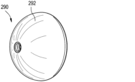
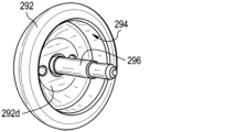
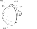
図8A及び図8Bに示されるように、本明細書で「グレノスフィア」と呼ばれる場合があるプロテーゼヘッド290は、実質的に半球形状の本体292を有し得る。グレノスフィア290を関節窩受け部260に取り付けるために、グレノスフィア本体292は、円盤形状の関節窩受け部プラットフォーム262と嵌合するように構成された開口空洞294を画定し得る。いくつかの実施形態では、グレノスフィア290及び関節窩受け部260は、関節窩受け部プラットフォーム262が空洞294内に受容されたときにテーパロックを形成するように構成され得る。
8A and 8B, the
あるいは、又は加えて、グレノスフィア290を関節窩受け部260に取り付けるための連結要素296は、グレノスフィア本体292の遠位向き表面292dから遠位方向に突出し得る。例示される実施形態に示されるように、連結要素296は、関節窩受け部260のボア266内にロックするように構成されたねじ付き又はねじなしシャフトであり得る。例えば、いくつかの実施形態では、グレノスフィア290を操作して、連結要素296を関節窩受け部260のボア266内にねじ込むか又はプレス嵌合することができる。当業者であれば、グレノスフィア及び関節窩受け部は、あるコンポーネントを別のコンポーネントに対して固定するための他の技術及び/又は機構を使用して、一緒に取り付けられ得ることを認識するであろう。
Alternatively, or in addition, a connecting
いくつかの実施形態では、関節窩受け部260及びグレノスフィア290のうちのいずれか及び全ては、インプラントを形成するための任意の数の埋め込み可能な金属材料又は他の生体適合性材料から作製され得る。インプラントの種々のコンポーネントを形成するのに好適な材料のいくつかの非限定的な例としては、チタン、タンタル、コバルトクロム、ステンレス鋼、及び当業者に既知の他の金属、並びに限定されないがポリエーテルエーテルケトン(PEEK)及び超高分子量ポリエチレン(UHMWPE)などのいくつかのプラスチック材料が挙げられ得る。場合によっては、種々のコンポーネント(例えば、関節窩受け部260及びグレノスフィア290)を同じ材料から作製することができ、一方で、他の実施形態では、1つ以上のコンポーネントを異なる材料から作製することができる。加えて、当業者は、いくつかの異なる材料の混合物を使用して、本明細書について提供される、又はそうでなければ本開示から導出可能である、インプラントの任意のコンポーネントを形成することができることを認識するであろう。
In some embodiments, any and all of the
図9A~図9Dは、患者の肩甲骨内に逆型肩関節インプラント200を配設する方法の例示的な実施形態の概略図である。例示される実施形態では、逆型肩関節インプラント200は、解剖学的肩関節インプラント100の解剖学的関節窩コンポーネント150を取り外して逆型関節窩コンポーネント250に置換する、肩関節全置換術の解剖学的-逆型変換の一部として配設され得る。例示される実施形態は解剖学的-逆型変換を説明しているが、当業者であれば、本明細書に提供される逆型肩関節インプラント200は、解剖学的関節窩インプラントを事前に配設する必要なく配設され得ることを認識するであろう。
9A-9D are schematic diagrams of an exemplary embodiment of a method for disposing a
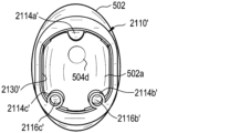
図9A及び図9Bを参照すると、フレーム110’は、関節窩骨502に固定され、穿孔504c’を含む関節窩骨の凹形形状部分502aを露出した状態で示されている。例示される実施形態では、フレーム110’は、骨アンカーポケット114a、114bに通して挿入された多軸骨ねじ510によって骨に固定される。例示された解剖学的-逆型変換では、固定されたフレーム110’は、図5A~図5Cに関連して上述した解剖学的全肩関節形成術の一部として以前に配設されたフレーム(例えば、110)と同じであり得る。以前に配設された解剖学的関節窩インプラントの解剖学的関節窩コンポーネント150(図示せず)は、前処理工程で取り外され得る。
9A and 9B, the frame 110' is shown secured to the
フレームアダプタ140は、フレーム110’の開口130’内に挿入され得る(部分的透明画で示される)。挿入されると、フレームアダプタ140は、アダプタがフレーム110’の対向する脚部の間で、フレーム開口130’を横切って実質的に水平に延在するように操作され得る。例えば、例示される実施形態に示されるように、フレームアダプタ140は、フレームアダプタ140の末端部140a及び140bが環状フレーム本体112’の遠位表面内に画定された対応する凹部120e’及び120f’内に受容されるように、フレーム開口130’内で操作され得る。いくつかの実施形態では、凹部120e’及び120f’は、フレーム110’内で水平にそろって回転される際に、フレームアダプタ140にクリアランスを提供するように画定され得る。いくつかの実施形態では、フレームアダプタ140の断面プロファイルは、アダプタがフレーム110の対向する凹部120e’及び120f’内で位置合わせされるときに、孔504c’を少なくとも部分的に取り囲むように構成され得る。
The
図9Cを参照すると、関節窩受け部260は、ポスト268(図9Dに示す)が穿孔504cに挿入され、貫通孔264a及び264bがフレームアダプタ140のロックねじ孔142a及び142bと位置合わせされるように、フレーム110上に装着され得る。いくつかの実施形態では、関節窩受け部260の貫通孔264及びフレームアダプタ140のロックねじ孔142は、その遠位表面内に画定された凹部262r(図7Bを参照)がフレームアダプタ140と嵌合ように関節窩受け部プラットフォーム262を配向することによって位置合わせされ得る。ロックねじ520a及び520b(集合的に520)は、関節窩受け部プラットフォーム262の貫通孔264内に、及びフレームアダプタ140のロックねじ孔142内に、遠位方向に打ち込まれるか、ないしは別の方法で挿入され得る。ロックねじ520がフレームアダプタ140内に挿入されると、関節窩受け部プラットフォーム262及びフレームアダプタ140は、それらが環状フレーム本体112’に押し付けられるように互いに向かって移動し得る。
9C, the
図9Dを参照すると、グレノスフィア290は、関節窩受け部260に取り付けられ得る。例えば、いくつかの実施形態では、グレノスフィア本体292の連結要素296(不可視)は、関節窩受け部260の中心ボア266(図9C)にねじ込まれるか、又はプレス嵌合され得る。加えて、又はあるいは、グレノスフィア290及び関節窩受け部260は、円盤形状の関節窩受け部プラットフォーム262がグレノスフィア本体292内に画定された空洞294(不可視)内に受容されるとき、テーパロックを形成し得る。
9D, the
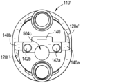
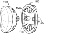
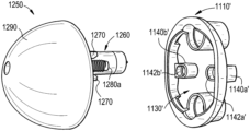
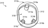
図10A~図10Dは、解剖学的肩関節インプラント1100の別の例示的な実施形態を示す。プロテーゼインプラント1100は、フレーム1110及び解剖学的関節窩コンポーネント1150を含み得る。フレーム1110は、骨に固定され得、解剖学的関節窩コンポーネント1150をフレームに取り付けるための複数の取り付けインターフェース1120を含み得る。加えて、フレーム1110は、開口1130を画定し得、関節窩コンポーネント1150の遠位部分1150dは、フレームに取り付けられたときに開口1130を通して骨と直接接触し得る。以下により詳細に論じられるように、いくつかの実施形態では、フレーム1110は、肩関節インプラント1100が逆型肩関節インプラントに変換されることを可能にするように構成され得る。
10A-10D show another exemplary embodiment of an
図11A~図11Dに示されるように、フレーム1110は、開口1130を画定する環状形状の本体1112と、骨アンカーポケット1114a及び1114b(集合的に1114)と、スナップ嵌めコネクタインターフェース1120a、1120b、1120c、及び1120d(集合的に1120)と、ロックねじポケット1140a及び1140b(集合的に1140)と、を含み得る。以下に記載されるか、又は当業者によって容易に理解されることを除いて、フレーム1110、環状形状のフレーム本体1112、骨アンカーポケット1114、スナップ嵌めコネクタインターフェース1120、及び開口1130は、上述のフレーム110、環状形状のフレーム本体112、骨アンカーポケット114、スナップ嵌めコネクタインターフェース120、及び開口130と同じであるか、又は実質的に同じである。ゆえに、その構造及び機能の詳細な説明は、簡潔にするためにここでは省略する。
11A-11D, the
いくつかの実施形態では、ロックねじポケット1140は、ポケットがフレーム開口1130を通してアクセス可能であるように、環状フレーム本体1112の対向する脚部から内側に延在するように構成された片持ちブロックであり得る。いくつかの実施形態では、ロックねじポケット1140は、フレーム1110の中心横軸A-Aに沿って位置合わせされ得る。ロックねじポケット1140は、対応するロックねじ(図示せず)を受容するように構成された対応のねじ孔1142a及び1142b(集合的に1142)を画定し得る。例えば、図14A~図14Cに関連してより詳細に説明されるように、ロックねじポケット1140を使用して、逆型関節窩コンポーネントをフレーム1110に取り付けることができ、それによって別個のフレームアダプタの必要性を回避することができる。2つのロックねじポケット1140が図に示されているが、2つより多い又は少ないロックねじポケット(例えば、1、3、4、5、又は6つ以上のロックねじポケット)がフレーム1110の一部として含まれ得る。
In some embodiments, the locking screw pocket 1140 may be a cantilever block configured to extend inwardly from opposing legs of the
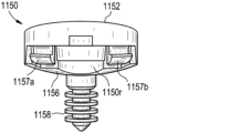
図12A~図12Dに示されるように、解剖学的関節窩コンポーネント1150は、近位部分1150p及び遠位部分1150dを含む概ね円盤形状の本体を有し得る。近位部分1150pは、凹形状の近位軸受表面1152と、遠位向き隆起部1154と、を含み得る。コンポーネント1150の遠位部分1150dは、凸形状の遠位表面1156と、遠位表面から実質的に垂直に突出する円筒形状のポスト1158と、を有し得る。以下に記載されるか、又は当業者によって容易に理解されることを除いて、限定するものではないがその近位部分1150p及び遠位部分1150dを含む、解剖学的関節窩コンポーネント1150は、限定するものではないがその近位部分150p及び遠位部分150dを含む、上述の解剖学的関節窩コンポーネント150と同じ又は実質的に同じである。ゆえに、その構造及び機能の詳細な説明は、簡潔にするためにここでは省略する。
12A-12D, the
解剖学的関節窩コンポーネント1150の遠位部分1150dは、フレーム1110の開口1130内に挿入するように構成されたベスポーク形状を有し得る。例えば、例示される実施形態では、遠位部分1150dのベスポーク形状は、フレーム開口1130の断面プロファイルのネガを概ね形成するように構成された断面プロファイルを有する。遠位部分1150はまた、骨アンカーポケット1114及びロックねじポケット1140を取り囲む(又は少なくとも部分的に取り囲む)ように構成された凹部(又は切欠部分)1150rを画定し得、そのようにして、関節窩コンポーネント1150のフレームへの取り付け中にポケットが干渉することを防止する。上記のように、遠位部分1150dは、患者の肩甲骨内の関節窩骨の実質的に凹状の表面と直接嵌合するように構成された概ね凸形状の遠位軸受表面1156を有し得、そのようにして、関節窩コンポーネント1150と骨との間の接触表面積を最大化し得る。
The
上述のように、フレーム1110は、解剖学的関節窩コンポーネント1150をフレームに取り付けるための複数のスナップ嵌めコネクタインターフェース1120を含み得る。図12A~図12Dを参照すると、解剖学的関節窩コンポーネント1150は、フレーム1110の対応するスナップ嵌めコネクタインターフェース1120a、1120b、1120c、及び1120d(集合的に1120)と結合するか、ないしは別の方法で係合するように構成された複数のスナップ嵌めコネクタ1157a、1157b、1157c、及び1157d(集合的に1157)を含み得る。例示される実施形態では、スナップ嵌めコネクタ1157のそれぞれは、関節窩コンポーネントの近位部分1150pの隆起部1154から遠位方向に突出するフック又はクランプのような形状であり得る。いくつかの実施形態では、スナップ嵌めコネクタ1157は、環状フレーム本体1112内に画定されたスナップ嵌めコネクタインターフェース1120の位置でフレーム1110上にスナップ嵌めするように構成され得る。当業者であれば、スナップ嵌めコネクタ1157は、解剖学的関節窩コンポーネント1150がフレーム1110上に押圧されたときにスナップ嵌めコネクタインターフェース1120を係合するための代替の形状及び/又は構成を有し得ることを認識するであろう。同様に、本開示は、コネクタ157に関して上に提供された雄型インターフェース(例えば、157、1157)及び雌型インターフェース(例えば、120、1120)により一般的に適用可能であり、インターフェース120は、コネクタ1157及びインターフェース1120に適用可能である。
As discussed above, the
図13A~図13Cは、患者の肩甲骨内に解剖学的肩関節インプラント1100を配設する方法の例示的な実施形態の概略図である。例示される実施形態では、解剖学的肩関節インプラント1100は、解剖学的肩関節全置換術の一部として埋め込まれ得、それにより、インプラント1100は、患者の肩甲骨の関節窩骨に固定されて、上腕骨プロテーゼのプロテーゼヘッド(例えば、図1Aの14)に対応する凹状の軸受表面を提供する。例示される構成は上述のインプラント1100を使用するが、インプラント1100に関連付けられる、ないしは別の方法でインプラント100と共に使用されるコンポーネントの少なくともいくつかは容易に視認できない場合がある。本明細書に提供される本開示、及びそれらの関連する図を考慮して、当業者は、インプラント1100の種々のコンポーネントが、どのように、患者の解剖学的構造の種々の部分に、並びに/又は図13A~図13Cに関して開示される処置と共に使用されるインプラント1100及び関連する工具(複数可)のコンポーネントに係合するのかを理解するであろう。
13A-13C are schematic diagrams of an exemplary embodiment of a method for disposing an
図13Aを参照すると、患者の肩甲骨の関節窩骨502は、関節窩骨502の表面が、フレーム1110及び解剖学的関節窩コンポーネント1150の凸形状の遠位表面1112d、1156にそれぞれ実質的に一致するようにリーマー加工され得る。当業者であれば、リーマー(図示せず)又は他の工具(複数可)を使用して、フレーム1110及び関節窩コンポーネント1150の凸面と同じ又は実質的に同じ曲率半径を有するほぼ滑らかな凹面を有するように、関節窩骨502を準備し得ることを認識するであろう。
13A, the
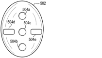
更に、図13Aに示されるように、骨内へと遠位方向に突出するように構成されたインプラント1100のコンポーネントを受容するために、1つ以上の孔を関節窩骨502に穿孔することができる。図5Aに関連して上述したように、孔504a及び504bは、フレーム1110の骨アンカーポケット1114a及び1114bを受容する直径で穿孔され得、孔504cは、解剖学的関節窩コンポーネント150の骨係合ポスト1158を受容するように穿孔され得る。加えて、例示される実施形態では、孔504d及び504eは、ロックねじポケット1140a及び1140bを受容するように骨に穿孔され得る。当業者であれば、ストップドリル(stop drill)又は他の骨用リーマー加工工具(複数可)を使用して、骨に穿孔し得ることを認識するであろう。いくつかの実施形態では、1つ以上のガイドプレート(図示せず)及び/又は他の位置合わせ工具を使用して、適切な位置に穿孔することができる。
13A, one or more holes can be drilled in the
図13Bを参照すると、開口1130を画定するフレーム1110は、関節窩骨502に固定され得る。例えば、例示される実施形態では、4つのポケット(すなわち、骨アンカーポケット1114及びロックねじポケット1142)がボア504a、504b、504d、及び504e(不可視)内に挿入されるように、フレーム1110を関節窩骨502上に装着することができる。フレーム1110が関節窩骨502上に装着された後、フレームは、多軸骨ねじ510又は他の骨アンカーを骨アンカーポケット1114のそれぞれに通して遠位方向に打ち込むか、ないしは別の方法で挿入することによって、骨に固定され得る。いくつかの実施形態では、ねじ回し(図示せず)を使用して、骨ねじ510を関節窩骨に打ち込むことができる。骨に固定されると、フレーム1110の開口1130は、穿孔504c’を含む関節窩骨502の凹形状部分502aを露出させる。
13B, the
図13Cを参照すると、関節窩コンポーネントの遠位部分1150dがフレーム開口130を通して関節窩骨502aと直接接触するように、解剖学的関節窩コンポーネント1150をフレーム1110に取り付けることができる。例えば、図示されるように、関節窩コンポーネント1150の凸形状の遠位表面1156及びポスト1158は、フレーム開口1130を通して関節窩骨502aと直接接触し得る。関節窩コンポーネント1150の凸形状の遠位表面1156及びフレーム1110の凸形状の遠位表面1112dを、同じ又は実質的に同じ曲率半径R’を有するように構成することによって、直接コンポーネントと骨との接触表面積を最大化させることができる。
13C, the
いくつかの実施形態では、解剖学的関節窩コンポーネント1150は、ポスト1158を開口1130に通して穿孔504c’内に挿入し、該コンポーネントを開口1130に通して、フレームにスナップ嵌めされるまで遠位方向に押すことによって、フレーム1110に取り付けられ得る。例えば、解剖学的関節窩コンポーネント1150は、コンポーネント(不可視)のスナップ嵌めコネクタ1157がフレーム1110のスナップ嵌めコネクタインターフェース1120(不可視)と結合するか、ないしは別の方法で係合するとき、フレーム上にスナップ嵌めされ得る。ポスト1158は、プレス嵌合を可能にし得る、穿孔504cの直径に対して僅かにオーバーサイズであり得る。
In some embodiments, the
以下により詳細に記載されるように、解剖学的-逆型変換を容易にするために、以前に配設された解剖学的肩関節インプラント1100の固定されたフレーム1110を再使用するように構成され得る、逆型肩関節インプラントが本明細書に提供される。例えば、フレーム1110のロックねじポケット1140を使用して、逆型関節窩コンポーネントをフレームに取り付けることができ、それによって別個のフレームアダプタの必要性を回避することができる。
As described in more detail below, provided herein is a reverse shoulder implant that may be configured to reuse the fixed
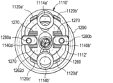
図14A~図14Cは、逆型肩関節インプラント1200の例示的な実施形態を示す。プロテーゼインプラント1200は、フレーム1110’及び逆型関節窩コンポーネント1250を含み得る。図示のように、逆型関節窩コンポーネント1250は、フレーム上にコンポーネントを装着し、ロックねじ1280a及び1280b(集合的に1280)を該コンポーネントに通して、フレームのロックねじポケット1140a’及び1140b’(集合的に1140’)内に画定されたねじ付き孔1142a及び1142b(集合的に1142)内へと遠位方向に打ち込むか、ないしは別の方法で挿入することによって、フレーム1110’に直接取り付けられ得る。
14A-14C show an exemplary embodiment of a
例示される実施形態に示されるように、フレーム1110’は、環状形状の本体1112’と、骨アンカーポケット1114a’及び1114b’(集合的に1114’)と、スナップ嵌めコネクタインターフェース1120a’、1120b’、1120c’、及び1120d’(集合的に1120’)と、ロックねじポケット1140’と、を含み得る。以下に記載されるか、又は当業者によって容易に理解されることを除いて、フレーム1110’は、上述のフレーム1110と同じ又は実質的に同じである。ゆえに、フレーム1110’の構造及び機能の詳細な説明は、簡潔にするためにここでは省略する。
As shown in the illustrated embodiment, the frame 1110' may include an annular shaped body 1112', bone anchor pockets 1114a' and 1114b' (collectively 1114'), snap-
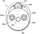
図15A~図15Cに示されるように、逆型関節窩コンポーネント1250は、ベースプレート1260と、プロテーゼヘッド1290と、フレームロックねじ1280a及び1280b(集合的に1280)と、グレノスフィアロックねじ1282a及び1282b(集合的に1282)と、中心骨ねじ1284と、を含み得る。いくつかの実施形態では、逆型関節窩コンポーネント1250の構成コンポーネント1260、1290、1280、1282、及び1284は、フレーム1110’への取り付けの前に組み立てられ得る。
15A-15C, the
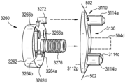
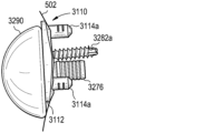
本明細書で「関節窩受け部」と呼ばれる場合があるベースプレート1260は、概ね円盤形状のプラットフォーム1262と、プラットフォームの遠位表面1262dから外向きに延在する円筒形状のポスト1268と、を含み得る。貫通孔1264a及び1264b(集合的に1264)は、逆型関節窩コンポーネント1250をフレーム1110’に取り付けるためのロックねじ1280を受容するため、関節窩受け部プラットフォーム1262内に画定され得る。貫通孔1264は、ねじ付き又はねじなしとすることができる。貫通孔1264は、ロックねじ1280が、垂直又は斜めの角度でフレーム1110’のロックねじポケット1140’内に打ち込まれるか、ないしは別の方法で挿入され得るように配向され得る。いくつかの実施形態では、ガイドレール1270は、関節窩受け部プラットフォーム1262の遠位表面1262dから外向きに突出し得る。ガイドレール1270は、逆型関節窩コンポーネント1250のロックねじ1280をフレーム1110’のロックねじポケット1140’と位置合わせするように構成され得る。
The
いくつかの実施形態では、円筒形状のポスト1268は、関節窩受け部プラットフォーム1262の遠位表面1262dから遠位方向に延在するように構成され得る。関節窩受け部ポスト1268は、骨、例えば、患者の肩甲骨の関節窩骨に形成された孔又は空洞内に埋め込まれるように構成され得る。いくつかの実施形態では、中心貫通孔1266は、関節窩受け部プラットフォーム1262及び関節窩受け部ポスト1268の長さを通って延在するように画定され得る。任意選択的に、中心骨ねじ1284は、例えば、追加の固定支持体を提供するために、中心孔1266を通って、関節窩骨内に打ち込まれるか、ないしは別の方法で挿入され得る。
In some embodiments, a
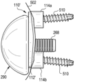
本明細書で「グレノスフィア」と呼ばれる場合があるプロテーゼヘッド1290は、実質的に半球形状の本体1292を有し得る。逆型関節窩コンポーネント1250を形成するために、グレノスフィア1290は、グレノスフィアロックねじ1282を、関節窩プラットフォーム1262内に画定された貫通孔1263a及び1263b(集合的に1263)に通してグレノスフィア本体1292内に近位方向へ打ち込む、ないしは別の方法で挿入することによって、関節窩受け部1260に取り付けられ得る。以下により詳細に記載されるように、グレノスフィア本体1292は、円盤形状の関節窩受け部プラットフォーム1262と嵌合するように構成され得る開口空洞1294(図16Cを参照)を画定し得る。いくつかの実施形態では、グレノスフィア1290及び関節窩受け部1260は、関節窩受け部プラットフォーム1262が空洞1294内に受容されたときにテーパロックを形成するように構成され得る。当業者であれば、グレノスフィア及び関節窩受け部は、あるコンポーネントを別のコンポーネントに対して固定するための他の技術及び/又は機構を使用して、一緒に取り付けられ得ることを認識するであろう。以下により詳細に記載されるように、関節窩受け部1260及びグレノスフィア1290によって形成される逆型関節窩コンポーネント1250は、該コンポーネントをフレーム上に装着し、フレームのロックねじポケット1140’内にロックねじ1280を打ち込むか、ないしは別の方法で挿入することによって、フレーム1110’に取り付けられ得る。更に、当業者であれば、本開示を考慮すると、逆型関節窩コンポーネント1250が本明細書に提供されるようなプロテーゼコンポーネントであり、ベースプレート1260は、プロテーゼコンポーネントの遠位向き表面の一部であるか、又はそこに連結されており、半球形状のプロテーゼヘッド1290は、プロテーゼコンポーネントの近位軸受表面の一部であるか、又はそれに連結されていることを理解するであろう。
The
図16A~図16Dは、患者の肩甲骨内に逆型肩関節インプラント1200を配設する方法の例示的な実施形態の概略図である。例示される実施形態では、逆型肩関節インプラント1200は、解剖学的肩関節インプラント1100の解剖学的関節窩コンポーネント1150を取り外して逆型関節窩コンポーネント1250に置換する、肩関節全置換術の解剖学的-逆型変換の一部として配設され得る。例示される実施形態は解剖学的-逆型変換を説明しているが、当業者であれば、本明細書に提供される逆型肩関節インプラント1200は、解剖学的関節窩インプラントを事前に配設する必要なく配設され得ることを認識するであろう。
16A-16D are schematic diagrams of an exemplary embodiment of a method for disposing a
図16Aを参照すると、フレーム1110’は、関節窩骨502に固定され、穿孔504c’を含む関節窩骨の凹形状部分502aを露出した状態で示されている。例示される実施形態では、フレーム1110’は、骨アンカーポケット1114a’、1114b’に通して打ち込まれた、ないしは別の方法で挿入された多軸骨ねじ510によって、骨に固定される。例示された解剖学的-逆型変換では、固定されたフレーム1110’は、図11A~図11Dに関連して上述した解剖学的全肩関節形成術の一部として以前に配設されたフレーム(例えば、1110)と同じであり得る。以前に配設された解剖学的関節窩インプラントの解剖学的関節窩コンポーネント1150(図示せず)は、前処理工程で取り外され得る。
16A, the frame 1110' is shown secured to the
図16Bを参照すると、組み立てられた逆型関節窩コンポーネント1250は、ポスト1268がフレーム開口1130’を通って関節窩骨502aの穿孔504c(不可視)内に挿入されるように、フレーム1110’上に装着され得る。逆型関節窩コンポーネントは、関節窩受け部プラットフォーム1262dの遠位表面1262dから突出するフレームロックねじ1280a及び1280bが、フレーム1110’のロックねじポケット1140a’及び1140b’と位置合わせされるように操作され得る。いくつかの実施形態では、ロックねじ1280は、例えば、図14Cに示されるように、ポケットがガイドレール1290の間に位置付けられるまで、逆型関節窩コンポーネントを回転させることによって、ロックねじポケット1140と位置合わせされ得る。
16B, the assembled reverse
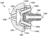
図16Cを参照すると、逆型関節窩コンポーネント1250は、フレームロックねじ1280を、ロックねじポケット1140内に画定されたねじボア1142内に打ち込むか、ないしは別の方法で挿入することによって、フレーム1110’に固定され得る。いくつかの実施形態では、ロックねじ1280は、グレノスフィア本体1292の頂点Vに画定された開口部又はポート1296を通してアクセスされ得る。ポート1296は、ロックねじ1280の対応のヘッドが露出され得る空洞1294につながるように構成され得る。例えば、ねじ回し(図示せず)をポート1296に通してグレノスフィア本体1292の空洞1294内に挿入して、ロックねじ1280を関節窩受け部プラットフォーム1262の孔1264に通してフレーム1110’のロックねじポケット1140’内に打ち込むことができる。任意選択的に、例えば、追加の固定支持体を提供するため、ねじ回しをポート1296に通してグレノスフィア本体1292の空洞1294内に挿入して、中心骨ねじ1284を関節窩受け部プラットフォーム1260の中心孔1266に通して関節窩骨内に打ち込むことができる。
16C, the
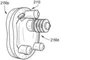
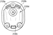
図17A~図17Dは、解剖学的肩関節インプラント2100の更に別の例示的な実施形態を示す。プロテーゼインプラント2100は、フレーム2110及び解剖学的関節窩コンポーネント2150を含む。フレーム2110は、骨に固定され得、解剖学的関節窩コンポーネント2150をフレームに取り付けるための複数の取り付けインターフェース2120a、2120b、及び2120c(集合的に2120)を含み得る。加えて、フレーム2110は、開口2130を画定し得、関節窩コンポーネント2150の遠位部分2150dは、フレームに取り付けられたときに開口2130を通して骨と直接接触し得る。以下により詳細に記載されるように、いくつかの実施形態では、フレーム2110は、肩関節インプラント2100が逆型肩関節インプラントに変換されることを可能にするように構成され得る。
17A-17D show yet another exemplary embodiment of an
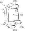
図18A~図18Dに示されるように、フレーム2110は、開口2130を画定する環状形状の本体2112と、固定ペグ2114a、2114b、2114c(集合的に2114)と、スナップ嵌めコネクタインターフェース2120a、2120b、及び2120c(集合的に2120)と、を含み得る。以下に記載されるか、又は当業者によって容易に理解されることを除いて、フレーム2110、環状形状のフレーム本体2112、スナップ嵌めコネクタインターフェース2120、及び開口2130は、上述のフレーム110、環状形状のフレーム本体112、スナップ嵌めコネクタインターフェース120、及び開口130と同じであるか、又は実質的に同じである。ゆえに、その構造及び機能の詳細な説明は、簡潔にするために省略する。
18A-18D, the
例示される実施形態では、フレーム2110は、フレームを骨に固定するように構成された3つのペグ2114a、2114b、及び2114c(集合的に2114)を含む。図21A~図21Cに関連してより詳細に記載されるように、固定ペグ2114は、解剖学的肩インプラント1100を逆型肩インプラントに変換するためにも使用され得る。固定ペグ2114は、フレーム2110から遠位方向に延在する実質的に円筒形の形状を有し得る。例えば、図示のように、固定ペグ2114aはフレーム本体2112の上端部2112sに配設され得、固定ペグ2114b及び2114cは下端部2112iに配設され得る。
In the illustrated embodiment, the
3つの骨固定ペグ2114が示されているが、フレームは、フレームを骨に固定するために3つより多い又は少ないペグ(例えば、1、2、4、5、又は6つ以上のペグ)を含み得る。いくつかの実施形態では、固定ペグ2114の外側表面及びフレーム2110の遠位表面2112dは、主な事業所をRaynham,Massachusettsに有するDePuy Synthes Products,Inc.から入手可能なチタン系材料、GRIPTION(登録商標)など、骨への固定を強化する材料でコーティングされ得る。当業者であれば、フレームの骨への固定を強化するために、限定するものではないが、ヒドロキシアパタイト、POROCOAT(登録商標)、又は単純に高度にテクスチャ加工された表面を含む、他の材料を使用し得ることを認識するであろう。かかる材料を、本明細書に提供される、ないしは別の方法で本開示から導き出すことができる開示のいずれかと共に使用することができる。
Although three bone fixation pegs 2114 are shown, the frame may include more or less than three pegs (e.g., 1, 2, 4, 5, or 6 or more pegs) for fixing the frame to the bone. In some embodiments, the outer surfaces of the fixation pegs 2114 and the
固定ペグ2114のうちの1つ以上は、少なくとも部分的にペグの長さに沿って延在するねじ付きボアを画定し得る。例えば、例示される実施形態では、固定ペグ2114b及び2114cはそれぞれ、ねじ付きボア2116b及び2116c(集合的に2116)を画定する。図21A~図21Cに関連してより詳細に記載されるように、固定ペグのねじ付きボア2116は、別のプロテーゼコンポーネント、例えば、逆型関節窩コンポーネントをフレーム2110に取り付けるためのロックねじを受容するように構成され得る。
One or more of the fixation pegs 2114 may define a threaded bore extending at least partially along the length of the peg. For example, in the illustrated embodiment, fixation pegs 2114b and 2114c define threaded
いくつかの実施形態では、スナップ嵌めコネクタインターフェース2120は、フレーム2110の遠位表面2112d内に画定され得る。例えば、例示される実施形態に示すように、スナップ嵌めコネクタインターフェース2120a及び2120bは、固定ペグ2114aの隣接する側部上のフレーム2110の上端部2112sに画定され得、スナップ嵌めコネクタインターフェース2120cは、固定ペグ2114bと2114cとの間のフレームの下端部2112iに画定され得る。4つのスナップ嵌めコネクタインターフェース2120が示されているが、フレームは、解剖学的関節窩コンポーネント2150をフレームに取り付けるために4つよりも多い又は少ないスナップ嵌めコネクタインターフェースを画定し得る(例えば、1、2、3、5、6、7、又は8つ以上のスナップ嵌めコネクタインターフェース)。
In some embodiments, the snap-fit connector interfaces 2120 may be defined in the
図19A~図19Cに示されるように、解剖学的関節窩コンポーネント2150は、近位部分2150p及び遠位部分2150dを含む概ね円盤形状の本体を有し得る。近位部分2150pは、凹形状の近位軸受表面2152と、遠位向き隆起部2154と、を含み得る。コンポーネント2150の遠位部分2150dは、凸形状の遠位表面2156と、遠位表面から実質的に垂直に突出する円筒形状のポスト2158と、を有し得る。以下に記載されるか、又は当業者によって容易に理解されることを除いて、限定するものではないがその近位部分2150p及び遠位部分2150dを含む、解剖学的関節窩コンポーネント2150は、限定するものではないがその近位部分150p及び遠位部分150dを含む、上述の解剖学的関節窩コンポーネント150と同じ又は実質的に同じである。ゆえに、その構造及び機能の詳細な説明は、簡潔にするためにここでは省略する。
19A-19C, the
解剖学的関節窩コンポーネント2150の遠位部分2150dは、フレーム2110の開口2130内に挿入するように構成されたベスポーク形状を有し得る。例えば、例示される実施形態では、遠位部分2150dのベスポーク形状は、フレーム開口2130の断面プロファイルのネガを概ね形成するように構成された断面プロファイルを有する。遠位部分2150はまた、固定ペグ2114を少なくとも部分的に取り囲むように構成された複数の凹部(又は切欠部分)2150rを画定し得、そのようにして、解剖学的関節窩コンポーネント2150のフレームへの取り付け中にペグが干渉することを防止する。上記のように、遠位部分2150dは、患者の肩甲骨内の関節窩骨の実質的に凹状の表面と直接嵌合するように構成された概ね凸形状の遠位軸受表面2156を有し得、そのようにして、関節窩コンポーネント2150と骨との間の接触表面積を最大化し得る。
The
上述のように、フレーム2110は、解剖学的関節窩コンポーネント2150をフレームに取り付けるための複数のスナップ嵌めコネクタインターフェース2120を含み得る。例示される実施形態では、解剖学的関節窩コンポーネント2150は、フレーム2110の対応するスナップ嵌めコネクタインターフェース2120a、2120b、及び2120c(集合的に2120)と結合するか、ないしは別の方法で係合するように構成された複数のスナップ嵌めコネクタ2157a、2157b、及び2157c(集合的に2157)を含み得る。例示される実施形態では、スナップ嵌めコネクタ2157のそれぞれは、関節窩コンポーネントの近位部分2150pの隆起部2154から遠位方向に突出するフック又はクランプのような形状であり得る。いくつかの実施形態では、スナップ嵌めコネクタ2157は、環状フレーム本体2112内に画定されたスナップ嵌めコネクタインターフェース2120の位置でフレーム2110上にスナップ嵌めするように構成され得る。当業者であれば、スナップ嵌めコネクタ2157は、解剖学的関節窩コンポーネント2150がフレーム1110上に押圧されたときにスナップ嵌めコネクタインターフェース2120を係合するための代替の形状及び/又は構成を有し得ることを認識するであろう。同様に、本開示は、コネクタ157に関して上に提供された雄型インターフェース(例えば、157、1157、2157)及び雌型インターフェース(例えば、120、1120、2120)により一般的に適用可能であり、インターフェース120は、コネクタ2157及びインターフェース2120に適用可能である。
As described above, the
図20A~図20Cは、患者の肩甲骨内に解剖学的肩関節インプラント2100を配設する方法の例示的な実施形態の概略図である。例示される実施形態では、解剖学的肩関節インプラント2100は、解剖学的肩関節全置換術の一部として埋め込まれ得、それにより、インプラント2100は、患者の肩甲骨の関節窩骨に固定されて、上腕骨プロテーゼのプロテーゼヘッド(例えば、図1Aの14)の対応する凹状の軸受表面を提供する。例示される構成は上述のインプラント2100を使用するが、インプラント2100に関連付けられる、ないしは別の方法でインプラント2100と共に使用されるコンポーネントの少なくともいくつかは容易に視認できない場合がある。本明細書に提供される本開示、及びそれらの関連する図を考慮して、当業者は、インプラント2100の種々のコンポーネントが、どのように、患者の解剖学的構造の種々の部分に、並びに/又は図20A~図20Cに関して開示される処置と共に使用されるインプラント2100及び関連する工具(複数可)のコンポーネントに係合するのかを理解するであろう。
20A-20C are schematic diagrams of an exemplary embodiment of a method for disposing an
図20Aを参照すると、患者の肩甲骨の関節窩骨502は、関節窩骨502の表面が、フレーム2110の凸形状の遠位表面2112d及び解剖学的関節窩コンポーネント2150の凸形状の遠位表面2156にそれぞれ実質的に一致するようにリーマー加工され得る。当業者であれば、リーマー(図示せず)又は他の工具(複数可)を使用して、フレーム2110及び関節窩コンポーネント2150の凸面と同じ又は実質的に同じ曲率半径を有するほぼ滑らかな凹面を有するように、関節窩骨502を準備し得ることを認識するであろう。
20A, the
更に、図20Aに示されるように、骨内へと遠位方向に突出するように構成されたインプラント2100のコンポーネントを受容するために、1つ以上の孔を関節窩骨502に穿孔することができる。ボア504a、504b、及び504cは、フレーム2110の骨固定ペグ2114a、2114b、及び2114cを受容する直径で穿孔され得る。加えて、ボア504dは、解剖学的関節窩コンポーネント2150の骨係合ポスト2158を受容するように穿孔され得る。当業者であれば、ストップドリル又は他の骨用リーマー加工工具(複数可)を使用して、骨に穿孔し得ることを認識するであろう。いくつかの実施形態では、1つ以上のガイドプレート(図示せず)及び/又は他の位置合わせ工具を使用して、適切な位置に穿孔することができる。
20A, one or more holes can be drilled into the
図20Bを参照すると、開口2130を画定するフレーム2110は、関節窩骨502に固定され得る。例えば、例示される実施形態では、骨固定ペグ2114a、2114b、及び2114cを対応の孔504a、504b、及び504c(不可視)に挿入することによって、フレーム2110が関節窩骨502に固定され得る。ペグ2114は、プレス嵌合を可能にし得る、穿孔504a、504b、及び504cの直径に対して僅かにオーバーサイズであり得る。フレーム2110が骨に固定されると、フレーム2100の開口2130は、穿孔504dを含む関節窩骨502の凹形状部分502aを露出させ得る。
20B, the
図20Cを参照すると、解剖学的関節窩コンポーネント2150は、コンポーネントの遠位部分2150dがフレーム開口2130を通して関節窩骨502aと直接接触するように、フレーム2100に取り付けられ得る。例えば、図示のように、関節窩コンポーネント2150の凸形状の遠位表面2156及びポスト2158は、フレーム開口2130を通して関節窩骨502aと直接接触し得る。関節窩コンポーネント2150の凸形状の遠位表面2156及びフレーム2110の凸形状の遠位表面2112dを、同じ又は実質的に同じ曲率半径R’’を有するように構成することによって、直接コンポーネントと骨との接触表面積を最大化させることができる。
20C, the
いくつかの実施形態では、解剖学的関節窩コンポーネント2150は、ポスト2158をフレーム開口2130に通して穿孔504dに挿入し、該コンポーネントを開口に通して、フレームにスナップ嵌めされるまで遠位方向に押すことによって、フレーム2110に取り付けられ得る。例えば、解剖学的関節窩コンポーネント2150は、コンポーネント(不可視)のスナップ嵌めコネクタ2157がフレーム2110のスナップ嵌めコネクタインターフェース2120(不可視)と結合するか、ないしは別の方法で係合するとき、フレーム上にスナップ嵌めされ得る。ポスト2158は、プレス嵌合を可能にし得る、穿孔504d’の直径に対して僅かにオーバーサイズであり得る。
In some embodiments, the
図21A~図21Cに関連して以下により詳細に記載されるように、逆型肩関節インプラントは、解剖学的-逆型変換を容易にするために、以前に配設された解剖学的肩関節インプラント2100の固定されたフレーム2110を再使用するように構成され得る。例えば、フレーム2110の1つ以上の固定ペグ2114のねじ付きボア2116を使用して、逆型関節窩コンポーネントをフレームに取り付けることができる。
As described in more detail below in connection with FIGS. 21A-21C, the reverse shoulder implant may be configured to reuse the fixed
図21A~図21Dは、逆型肩関節インプラント2200の例示的な実施形態を示す。プロテーゼインプラント2200は、フレーム2110’及び逆型関節窩コンポーネント2250を含み得る。例示される実施形態では、フレーム2110’は、開口2130’を画定する環状形状の本体2112’と、固定ペグ2114a’、2114b’、2114c’(集合的に2114)と、スナップ嵌めコネクタインターフェース2120a’、2120b’、及び2120c’(集合的に2120)と、を含み得る。以下に記載されるか、又は当業者によって容易に理解されることを除いて、フレーム2110’は、上述のフレーム2110と同じ又は実質的に同じである。ゆえに、その構造及び機能の詳細な説明は、簡潔にするために省略する。
21A-21D show an exemplary embodiment of a
いくつかの実施形態では、逆型関節窩コンポーネント2250は、ベースプレート2260と、ベースプレートに連結された半球形状のプロテーゼヘッド2290と、を含み得る。当業者であれば、本開示を考慮すると、逆型関節窩コンポーネント2250が本明細書に提供されるようなプロテーゼコンポーネントであり、ベースプレート2260は、プロテーゼコンポーネントの遠位向き表面の一部であるか、又はそこに連結されており、半球形状のプロテーゼヘッド2290は、プロテーゼコンポーネントの近位軸受表面の一部であるか、又はそれに連結されていることを理解するであろう。図22A~図22Dに示されるように、本明細書で「関節窩受け部」と呼ばれる場合があるベースプレート2260は、近位部分2260p及び遠位部分2260dを含み得る。関節窩受け部2260の近位部分2260pは、近位表面2262p及び遠位表面2262dを有する概ね円盤形状のプラットフォーム2262を含み得る。関節窩受け部2260の遠位部分2260dは、フレーム2110’の開口2130’に挿入するように構成されたベスポーク形状を有し得る。例示される実施形態では、近位部分2260pは、関節窩受け部プラットフォーム2262の遠位表面2262dが隆起部を形成するように、遠位部分2260dから下方向にオフセットされ得る。ゆえに、遠位表面2262dは、関節窩受け部2260がフレーム2100’に取り付けられたときに、フレーム2110’の近位表面2112p’に当接し得る。
In some embodiments, the
1つ以上の貫通孔は、関節窩受け部プラットフォーム2262の近位表面2262p及び遠位表面2262dを通って延在するように画定され得る。例示される実施形態では、一対の貫通孔2264a及び2264b(集合的に2264)は、関節窩受け部プラットフォーム2262内に画定され、関節窩受け部2260がフレーム2110に装着されたときに固定ペグ2114b’及び2114b’内に画定されたねじ付きボア2116b’及び2116c’と位置合わせするように構成されている。2つの貫通孔2262が図に示されているが、2つより多い又は少ない貫通孔が関節窩受け部プラットフォーム2262内に画定され得る(例えば、1、3、4、5、又は6つ以上の貫通孔)。
One or more through holes may be defined extending through the
いくつかの実施形態では、遠位部分2260dのベスポーク形状は、フレーム開口2130’の断面プロファイルのネガを概ね形成するように構成された断面プロファイルを有し得る。遠位部分2260dはまた、フレーム2110’の固定ペグ2114’を取り囲む(又は少なくとも部分的に取り囲む)ように構成された凹部(又は切欠部分)2260rを画定し得、そうようにして、関節窩受け部2260のフレームへの取り付け中にペグが干渉するのを防止し得る。いくつかの実施形態では、関節窩受け部2260の遠位部分2260dは、患者の肩甲骨内の関節窩骨の実質的に凹面と直接嵌合するように構成された概ね凸形状の遠位軸受表面2266を有し得、そのようにして、関節窩受け部2260と関節窩骨との間の接触表面積を最大化し得る。当業者であれば、関節窩受け部2260の遠位軸受表面2266は、標的骨の対向する表面トポロジーに少なくとも部分的に依存して、異なる形状又は表面トポロジーを有し得ることを認識するであろう。これは、本開示で提供される軸受表面及びその相補的表面のいずれかにも当てはまる。
In some embodiments, the bespoke shape of the
いくつかの実施形態では、関節窩受け部2260の遠位部分2260dは、円筒形状のポスト2268を含み得る。例示される実施形態に示されるように、ポスト2268は、関節窩受け部2260の遠位表面2266に対して実質的に垂直に突出するように構成され得る。ポスト2268は、骨、例えば、患者の肩甲骨の関節窩骨に形成された孔又は空洞に挿入され得る。いくつかの実施形態では、貫通ボア2270は、ポスト2268を通って延在する長手方向中心軸B-Bに沿って関節窩受け部2260を通って延在するように画定され得る。図21A~図21Cに示されるように、中心ボア2270は、例えば、インプラントを骨に固定するために、骨ねじ2284を受容するように構成され得る。他の実施形態では、中心骨ねじを省略することができる。
In some embodiments, the
図23A及び図23Bに示されるように、本明細書で「グレノスフィア」と呼ばれる場合があるプロテーゼヘッド2290は、実質的に半球形状の本体2292を有し得る。グレノスフィア2290を関節窩受け部2260に取り付けるために、グレノスフィア本体2292は、関節窩受け部2260の円盤形状プラットフォーム2262と嵌合するように構成され得る開口空洞2294を画定し得る。いくつかの実施形態では、グレノスフィア2290及び関節窩受け部プラットフォーム2262は、関節窩受け部プラットフォームがグレノスフィア空洞2294内に受容されたときにテーパロックを形成するように構成され得る。
23A and 23B, the
あるいは、又は加えて、グレノスフィア2290を関節窩受け部2260に取り付けるために、連結要素2296が、グレノスフィア本体2292の空洞2294の遠位向き表面2294dから遠位方向に突出し得る。例示される実施形態に示されるように、連結要素2296は、関節窩受け部2260の中心貫通ボア2270内でロックするように構成されたねじ付き又はねじなしシャフトであり得る。例えば、いくつかの実施形態では、グレノスフィア2290を操作して、連結要素2296を関節窩受け部2260の貫通ボア2270内にねじ込むか又はプレス嵌合することができる。当業者であれば、グレノスフィア及び関節窩受け部は、あるコンポーネントを別のコンポーネントに対して固定するための他の技術及び/又は機構を使用して、一緒に取り付けられ得ることを認識するであろう。
Alternatively, or in addition, a connecting
図24A~図24Dは、患者の肩甲骨内に逆型肩関節インプラント2200を配設する方法の例示的な実施形態の概略図である。例示される実施形態では、逆型肩関節インプラント2200は、解剖学的肩関節インプラント1100の解剖学的関節窩コンポーネントを取り外して逆型関節窩コンポーネント1250に置換する、肩関節全置換術の解剖学的-逆型変換の一部として配設され得る。例示される実施形態は解剖学的-逆型変換を説明しているが、当業者であれば、本明細書に提供される逆型肩関節インプラント1200は、解剖学的インプラントを事前に配設する必要なく配設され得ることを認識するであろう。
24A-24D are schematic diagrams of an exemplary embodiment of a method for disposing a
図24Aを参照すると、フレーム2110’は、関節窩骨502に固定され、穿孔504d’を含む関節窩骨の凹形状部分502aを露出した状態で示されている。例示される実施形態では、フレーム2110’は、3つの固定ペグ2114a’、2114b’、及び2114c’によって骨に固定される。上述のように、固定ペグ2114’の外側表面及びフレーム2110’の遠位表面2112d’(不可視)は、GRIPTION(登録商標)などの骨への固定を強化する材料でコーティングされ得る。例示された解剖学的-逆型変換では、固定されたフレーム2110’は、図20A~図20Cに関連して上述した解剖学的全肩関節形成術の一部として以前に配設されたフレーム(例えば、2110)と同じであり得る。以前に配設された解剖学的関節窩インプラントの解剖学的関節窩コンポーネント2150(図示せず)は、前処理工程で取り外され得る。
24A, the frame 2110' is shown secured to the
図24Bを参照すると、関節窩受け部2260をフレーム2110’に取り付けることができる。関節窩受け部2260をフレーム2110’に取り付けるために、ポスト2268が以前に穿孔された孔504d’(不可視)に挿入されるように、関節窩受け部2260の遠位部分2260dがフレーム開口2130’を通って遠位方向に挿入され得る。関節窩受け部2260は、関節窩受け部プラットフォーム2262の遠位表面2262dがフレーム2110’の近位表面2112p’に当接するまで、引き続き遠位方向に挿入され得る。関節窩受け部2260がフレーム開口2130’に挿入されると、その遠位部分2260dのベスポーク形状は、関節窩受け部プラットフォーム2262の貫通孔2264を固定ペグ2114’のねじ付きボア2116’と位置合わせするための鍵として機能し得る。関節窩受け部2260をフレーム2110’に固定するために、ロックねじ2280a及び2280b(集合的に2280)は、関節窩受け部2260の貫通孔2264内、及び対応する固定ペグ2114’のねじ付きボア2116’内へと遠位方向に打ち込まれるか、ないしは別の方法で挿入され得る。任意選択的に、骨ねじ2284は、関節窩受け部1260の中心貫通ボア2270を通って骨内へと遠位方向に打ち込まれるか、ないしは別の方法で挿入され得る。
24B, the
図24Cを参照すると、グレノスフィア2290は、関節窩受け部2260に取り付けられ得る。例えば、いくつかの実施形態では、グレノスフィア本体2292の連結要素2296は、関節窩受け部2260の中心ボア2270にねじ込まれるか、又はプレス嵌合され得る。加えて、又はあるいは、グレノスフィア2290及び関節窩受け部2260は、円盤形状の関節窩受け部プラットフォーム2262がグレノスフィア本体2292内に画定された空洞2294(不可視)内に受容されるとき、テーパロックを形成し得る。
24C, the
いくつかの実施形態では、取り外し可能なコレット2298は、関節窩受け部2260の中心貫通ボア2270内に配設され得る。コレット2298は、連結要素の直径が中心貫通ボア2270の直径よりも小さいとき、グレノスフィア2290の連結要素2296と係合するような寸法とすることができる。例えば、いくつかの実施形態では、連結要素2296よりも大きい最大直径を有する骨ねじ2284をボア2270に通して骨502a内へと遠位方向に打ち込むか、ないしは別の方法で挿入した後、関節窩受け部2260の中心貫通ボア2270の直径を低減するために、コレット2298を挿入することができる。いくつかの実施形態では、コレット2298は、その内容全体が参照により本明細書に組み込まれる、「BASEPLATE OF A MODULLAR SHOULDER JOINT PROSTHESIS AND RELATED METHODS FOR IMPLANTING THE SAME」と題する、2018年7月24日に出願された米国特許出願第16/044,473号に示され、記載されているように実装され得る。
In some embodiments, a
図24Dに示すように、逆型関節窩コンポーネント2250のフレーム2110’への取り付けが完了すると、関節窩受け部2260の遠位部分2260dは、フレーム開口2130’を通して関節窩骨502aと直接接触し得る。例えば、例示される実施形態では、凸形状の遠位表面2266及び関節窩受け部2260のポスト2268は、フレーム開口2130を通して関節窩骨502aと直接接触し得る。関節窩受け部2260の凸形状の遠位表面2266及びフレーム2110’の凸形状の遠位表面2112dを、同じ又は実質的に同じ曲率半径R’’’を有するように構成することによって、直接コンポーネントと骨との接触表面積を最大化させることができる。
As shown in FIG. 24D, once the
図25A~図25Bは、逆型肩関節インプラント3200の別の例示的な実施形態を示す。プロテーゼインプラント3200は、フレーム3110及び逆型関節窩コンポーネント3250を含み得る。フレーム3110は、開口3130を画定し得、逆型関節窩コンポーネント3250の遠位部分3250dは、フレームに取り付けられたときに開口3130を通して骨と直接接触し得る。いくつかの実施形態では、逆型関節窩コンポーネント3250は、ベースプレート3260と、ベースプレートに連結された半球形状のプロテーゼヘッド3290と、を含み得る。任意追加的に、周囲骨ネジ3282a及び3282b(集合的に3282)は、インプラント3200を骨に更に固定するために、ベースプレート3260に通して打ち込まれるか、ないしは別の方法で挿入され得る。
25A-25B show another exemplary embodiment of a
以下に記載されるか、又は当業者によって容易に理解されることを除いて、フレーム3110は、上述のフレーム2110と同じ又は実質的に同じであり得る。例えば、例示される実施形態では、フレーム3110は、開口3130を画定する環状形状の本体3112と、固定ペグ3114a、3114b、及び3114c(集合的に3114)と、を含み得る。ゆえに、フレーム3110の構造及び機能の詳細な説明は、簡潔にするためにここでは省略する。
Except as described below or as would be readily understood by one of ordinary skill in the art, the
図26に示されるように、フレーム3110の固定ペグ3114のそれぞれは、実質的に円筒形の形状を有し、フレームから遠位方向に延在し得る。例えば、例示される実施形態では、固定ペグ3114aは、フレーム本体3112の上端部3112sに配置され得、固定ペグ3114b及び3114cは、下端部3112iに配設され得る。固定ペグ3114a、3114b、及び3114cのそれぞれは、ペグの長さに沿って少なくとも部分的に延在する対応するボア3116a、3116b、及び3116c(集合的に3116)を画定し得る。固定ペグ3114内に画定されたボア3116は、ねじ付き又はねじなしであり得る。非限定的な例として、例示される実施形態では、固定ペグ3114aのボア3116aはねじなしボアであり得、対応の固定ペグ3114b及び3114cのボア3116b及び3116cはねじ付きボアであり得る。
As shown in FIG. 26, each of the fixation pegs 3114 of the
図28A~図28Cに関連してより詳細に記載されるように、固定ペグ3114のボア3116は、逆型関節窩コンポーネント3250をフレーム3110に取り付けるように構成され得る。上記のように、いくつかの実施形態では、逆型関節窩コンポーネント3250は、ベースプレート3260と、ベースプレートに連結された半球形状のプロテーゼヘッド3290と、を含み得る。当業者であれば、本開示を考慮すると、逆型関節窩コンポーネント3250が本明細書に提供されるようなプロテーゼコンポーネントであり、ベースプレート3260は、プロテーゼコンポーネントの遠位向き表面の一部であるか、又はそこに連結されており、半球形状のプロテーゼヘッド3290は、プロテーゼコンポーネントの近位軸受表面の一部であるか、又はそれに連結されていることを理解するであろう。図27に示されるように、本明細書で「関節窩受け部」と呼ばれることもあるベースプレート3260は、近位部分3260p及び遠位部分3260dを含み得る。
28A-28C, the bore 3116 of the fixation peg 3114 may be configured to mount the
いくつかの実施形態では、関節窩受け部3260の近位部分3260pは、近位表面3262p及び遠位表面3262dを有する概ね円盤状のプラットフォーム3262を含み得る。いくつかの実施形態では、1つ以上の貫通孔は、関節窩受け部プラットフォーム3262の近位表面3262p及び遠位表面3262dを通って延在して、関節窩受け部をフレームに取り付けるためのロックねじ(図示せず)を受容するように画定され得る。例えば、例示される実施形態では、一対の貫通孔3264a及び3264b(集合的に3264)は、関節窩受け部プラットフォーム3262内に画定され、関節窩受け部3260がフレーム3110に装着されたときに固定ペグ3114b及び3114c内に画定されたねじ付きボア3116b及び3116cと位置合わせするように構成され得る。2つの貫通孔が図に示されているが、関節窩受け部をフレームに取り付けるために、2つより多い又は少ない貫通孔が関節窩受け部プラットフォーム3262内に画定され得る(例えば、1、3、4、5、又は6つ以上の貫通孔)。
In some embodiments, the
いくつかの実施形態では、関節窩受け部3260の遠位部分3260dは、プレート形状のフランジ3270と、フランジの上端部3270sに配設されたねじなしペグ3272と、を含み得る。ペグ3272は、フレーム3110の上端部3112sにおいて固定ペグ3114aのねじなしボア3116aに挿入されるように構成され得る。いくつかの実施形態では、フランジ3270は、フレーム3110の開口3130内に挿入するように構成された断面プロファイルを有し得る。例えば、フランジ3270の断面プロファイルは、フレーム開口部3130の断面プロファイルのネガを概ね形成するように構成され得る。フランジ3270はまた、フレーム3110の固定ペグ3114b及び3114cを取り囲む(又は少なくとも部分的に取り囲む)ように構成された凹部(又は切欠部分)3270rを画定し得、そのようにして、関節窩受け部3260のフレームへの取り付け中にペグが干渉するのを防止し得る。加えて、例示される実施形態に示されるように、貫通孔3266a及び3266b(集合的に3266)は、関節窩受け部プラットフォーム3262及びフランジ3270を通って延在するように画定され得る。このように、いくつかの実施形態では、貫通孔3266は、骨ねじなどを関節窩受け部3260に通して骨内へと遠位方向に打ち込むか、ないしは別の方法で挿入することを可能にするために使用され得る。
In some embodiments, the
いくつかの実施形態では、関節窩受け部3260の遠位部分3260dは、円筒形状のポスト3276を含み得る。例示される実施形態に示されるように、ポスト3276は、関節窩受け部3260のフランジ3270に対して実質的に垂直に突出するように構成され得る。ポスト3276は、骨、例えば、患者の肩甲骨の関節窩骨に形成されたボア又は空洞に挿入され得る。いくつかの実施形態では、貫通ボア3278は、ポスト3276を通って延在する長手方向中心軸C-Cに沿って、関節窩受け部3260を通って延在するように画定され得る。いくつかの実施形態では、中心ボア3278は、骨にインプラントを固定するための骨ねじ又は他のアンカー(図示せず)を受容するように構成され得る。いくつかの実施形態では、関節窩受け部3260の中心ボア3278は、プロテーゼヘッド3290の連結要素(不可視)を受容するように構成され得る。
In some embodiments, the
図28A~図28Cは、患者の肩甲骨内に逆型肩関節インプラント3200を配設する方法の例示的な実施形態の概略図である。例示される実施形態では、逆型肩関節インプラント3200は、以前に配設された解剖学的肩関節インプラントの解剖学的関節窩コンポーネントを取り外して逆型関節窩コンポーネント3250に置換する、肩関節全置換術の解剖学的-逆型変換の一部として配設され得る。例示される実施形態は解剖学的-逆型変換を説明しているが、当業者であれば、本明細書に提供される逆型肩関節インプラント3200は、解剖学的インプラントを事前に配設する必要なく配設され得ることを認識するであろう。
28A-28C are schematic diagrams of an exemplary embodiment of a method for disposing a
図28Aを参照すると、フレーム3110は、関節窩骨502に固定され、穿孔504dを含む関節窩骨の凹形状部分を露出した状態で示されている。例示される実施形態では、フレーム3110は、3つの固定ペグ3114a、3114b、及び3114cによって骨に固定される。例示される解剖学的逆型変換では、固定されたフレーム3110は、解剖学的全肩関節形成術の一部として以前に配設されたものであり得る。以前に配設された解剖学的関節窩インプラントの解剖学的関節窩コンポーネント(例えば、2150(図示せず))は、前処理工程で取り外され得る。
28A, the
関節窩受け部3260をフレーム3110に取り付けるために、ポスト3276が以前に穿孔された孔504dに挿入されるように、関節窩受け部3260の遠位部分3260dをフレーム開口3130に通して遠位方向に挿入し得る。関節窩受け部3260は、関節窩受け部プラットフォーム3262の遠位表面3262dがフレーム3110の近位表面3112pに当接するまで、引き続き遠位方向に挿入され得る。関節窩受け部3260は、フランジ3270から遠位方向に突出する回転防止ペグ3272が固定ペグ3114aのねじなしボア3116a内に挿入されるように操作され得る。関節窩受け部3260がフレーム開口2130’に挿入されると、遠位フランジ3270のベスポーク形状は、関節窩受け部プラットフォーム3262の貫通孔3264を固定ペグ3114b及び3114cのねじ付きボア3116b及び3116cと位置合わせするための鍵として機能し得る。
To attach the
図28Bを参照すると、いくつかの実施形態では、関節窩受け部3260をフレーム3110に固定するために、ロックねじ3280a及び3280b(集合的に3280)は、関節窩受け部3260の貫通孔3264(不可視)内、及び対応の固定ペグ3114b及び3114cのねじ付きボア3116b及び3116c(不可視)内へと遠位方向に打ち込まれるか、ないしは別の方法で挿入され得る。任意選択的に、周囲骨ネジ3282a及び3282b(集合的に3282)は、関節窩受け部3260の対応の貫通孔3266を通って骨内へと遠位方向に打ち込まれるか、ないしは別の方法で挿入され得る。
28B, in some embodiments, locking
図28Cを参照すると、本明細書で「グレノスフィア」と呼ばれる場合があるプロテーゼヘッド3290は、関節窩受け部3260に取り付けられ得る。例示される実施形態では、グレノスフィア3290は、実質的に半球形状の本体3292を有し得る。以下に記載されるか、又は当業者によって容易に理解されることを除いて、グレノスフィア3290は、上述のグレノスフィア2290と同じ又は実質的に同じであり得る。ゆえに、グレノスフィア3290の構造及び機能の詳細な説明は、簡潔にするためにここでは省略する。
28C, a
例えば、図24A~図24Dに関連して上述したように、グレノスフィア3290は、関節窩受け部プラットフォーム3262がグレノスフィア本体3292の開口空洞(不可視)内に受容されるときにテーパロックを形成することによって、関節窩受け部3260に取り付けられ得る。あるいは、又は加えて、グレノスフィア3290の連結要素(不可視)は、関節窩受け部3260の中心貫通ボア3278内にロックするように構成され得る。例えば、いくつかの実施形態では、グレノスフィア3290を操作して、連結要素を関節窩受け部3260の貫通ボア3270内にねじ込むか又はプレス嵌合することができる。当業者であれば、グレノスフィア及び関節窩受け部は、あるコンポーネントを別のコンポーネントに対して固定するための他の技術及び/又は機構を使用して、一緒に取り付けられ得ることを認識するであろう。
For example, as described above in connection with FIGS. 24A-24D, the
開示される実施形態の上の説明は、任意の当業者が本特許請求の範囲を行うこと、又は使用することを可能にするために提供される。これらの実施形態に対する種々の変更は、当業者には容易に明らかになり、かつ、本明細書で定義される一般的な原理は、特許請求の範囲の範囲から逸脱することなく、他の実施形態に適用され得る。したがって、本開示は、本明細書で示される実施形態に限定することを意図するものではなく、本明細書で開示される原理及び新規な特徴と合致する最も広い範囲が与えられるものである。本明細書において引用されている全ての刊行物及び参照文献は、それらの全体が参照により本明細書に明示的に組み込まれている。 The above description of the disclosed embodiments is provided to enable any person skilled in the art to make or use the present claims. Various modifications to these embodiments will be readily apparent to those skilled in the art, and the general principles defined herein may be applied to other embodiments without departing from the scope of the claims. Thus, the present disclosure is not intended to be limited to the embodiments shown herein, but is to be accorded the widest scope consistent with the principles and novel features disclosed herein. All publications and references cited herein are expressly incorporated herein by reference in their entirety.
〔実施の態様〕
(1) プロテーゼインプラントであって、
近位軸受表面及び遠位向き表面を有するプロテーゼコンポーネントであって、前記遠位向き表面は、前記近位軸受表面と対向している、プロテーゼコンポーネントと、
骨に固定されるように構成されたフレームであって、前記フレームは開口を画定し、前記プロテーゼコンポーネントの一部分は、前記開口を通して配設されるように構成されており、前記フレームは、1つ以上の取り付けインターフェースを含み、前記1つ以上の取り付けインターフェースは、前記プロテーゼコンポーネントの前記遠位向き表面が、前記フレームの前記開口を通って延在して骨と直接接触するように、前記プロテーゼコンポーネントを前記フレームに連結するように構成されている、フレームと、を備える、プロテーゼインプラント。
(2) 前記フレームが1つ以上の金属を含む、実施態様1に記載のインプラント。
(3) 前記プロテーゼコンポーネントが1つ以上のプラスチック材料を含む、実施態様1に記載のインプラント。
(4) 前記フレームが、前記フレームを骨に固定するための1つ以上の骨アンカーポケットを更に含み、前記1つ以上の骨アンカーポケットのそれぞれは、骨アンカーを骨内に挿入する際に通す貫通ボアを画定する、実施態様1に記載のインプラント。
(5) 前記1つ以上の骨アンカーポケットが、前記フレームの前記開口を通してアクセス可能である、実施態様4に記載のインプラント。
[Embodiment]
(1) A prosthetic implant, comprising:
a prosthetic component having a proximal bearing surface and a distal facing surface, the distal facing surface opposing the proximal bearing surface;
1. A prosthetic implant comprising: a frame configured to be secured to a bone, the frame defining an opening, a portion of the prosthetic component configured to be disposed through the opening, the frame including one or more attachment interfaces configured to couple the prosthetic component to the frame such that the distally facing surface of the prosthetic component extends through the opening in the frame and directly contacts bone.
2. The implant of claim 1, wherein the frame comprises one or more metals.
3. The implant of claim 1, wherein the prosthetic component comprises one or more plastic materials.
(4) The implant of claim 1, wherein the frame further comprises one or more bone anchor pockets for securing the frame to a bone, each of the one or more bone anchor pockets defining a through bore through which a bone anchor is inserted into the bone.
5. The implant of claim 4, wherein the one or more bone anchor pockets are accessible through the openings in the frame.
(6) 前記フレームが、前記フレームを骨に固定するための複数の固定ペグを更に含み、前記複数の固定ペグは、前記フレームから遠位方向に延在している、実施態様1に記載のインプラント。
(7) 前記プロテーゼコンポーネントが、前記プロテーゼコンポーネントの前記遠位向き表面から延在するポストを更に含み、前記ポストは、骨内に形成された空洞と係合するように構成されている、実施態様1に記載のインプラント。
(8) 前記プロテーゼコンポーネントの前記近位軸受表面に連結された半球形状を有するプロテーゼヘッドを更に備える、実施態様1に記載のインプラント。
(9) 前記フレームの前記1つ以上の取り付けインターフェースが、1つ以上のスナップ嵌めコネクタインターフェースを含む、実施態様1に記載のインプラント。
(10) 前記プロテーゼコンポーネントの前記1つ以上のスナップ嵌めコネクタが、前記フレームの前記1つ以上のスナップ嵌めコネクタインターフェースに取り付けられるとき、前記プロテーゼコンポーネントの前記遠位向き表面は、前記フレームの前記開口を通して骨と直接接触する、実施態様9に記載のインプラント。
6. The implant of claim 1, wherein the frame further comprises a plurality of fixation pegs for fixing the frame to bone, the plurality of fixation pegs extending distally from the frame.
7. The implant of claim 1, wherein the prosthetic component further comprises a post extending from the distally facing surface of the prosthetic component, the post configured to engage a cavity formed in a bone.
8. The implant of claim 1, further comprising a prosthetic head having a hemispherical shape coupled to the proximal bearing surface of the prosthetic component.
9. The implant of claim 1, wherein the one or more attachment interfaces of the frame include one or more snap-fit connector interfaces.
10. The implant of claim 9, wherein when the one or more snap-fit connectors of the prosthetic component are attached to the one or more snap-fit connector interfaces of the frame, the distally facing surface of the prosthetic component is in direct contact with bone through the opening in the frame.
(11) 前記フレームの前記1つ以上の取り付けインターフェースが、取り外し可能なフレームアダプタを含み、前記取り外し可能なフレームアダプタは、1つ以上のロックねじ孔を画定し、前記取り外し可能なフレームアダプタは、前記フレームの対向する脚部の間で、前記開口を横切って延在するように構成されている、実施態様1に記載のインプラント。
(12) 前記プロテーゼコンポーネントが、前記取り外し可能なフレームアダプタの前記1つ以上のロックねじ孔に対応する1つ以上の貫通孔を画定し、前記プロテーゼコンポーネントは、ロックねじを前記プロテーゼコンポーネントの前記1つ以上の貫通孔に通して、前記取り外し可能なフレームアダプタの前記1つ以上のロックねじ孔内に挿入することによって、前記フレームに連結されるように構成されている、実施態様11に記載のインプラント。
(13) 前記フレームの前記1つ以上の取り付けインターフェースが、前記開口を通してアクセス可能であり、1つ以上の対応するロックねじ孔を画定する、1つ以上のロックねじポケットを含む、実施態様1に記載のインプラント。
(14) 前記プロテーゼコンポーネントが、前記1つ以上のロックねじポケットの前記1つ以上のロックねじ孔に対応する1つ以上の貫通孔を画定し、
前記プロテーゼコンポーネントは、ロックねじを前記プロテーゼコンポーネントの前記1つ以上の貫通孔に通して、前記1つ以上のロックねじポケットの前記1つ以上のロックねじ孔内に挿入することによって、前記フレームに連結されるように構成されている、実施態様13に記載のインプラント。
(15) 前記フレームの前記1つ以上の取り付けインターフェースが、前記フレームを骨に固定するために前記フレームから突出している複数の固定ペグを含み、前記複数の固定ペグのうちの1つ以上の固定ペグは、その中に1つ以上のボアを画定し、
前記プロテーゼコンポーネントが、前記1つ以上の固定ペグ内に画定された前記1つ以上のボアに対応する1つ以上の孔を画定し、
前記プロテーゼコンポーネントは、ロックねじを前記プロテーゼコンポーネントの前記1つ以上の孔に通して、前記1つ以上の固定ペグ内に画定された前記1つ以上のボア内に挿入することによって、前記フレームに連結されるように構成されている、実施態様1に記載のインプラント。
11. The implant of claim 1, wherein the one or more mounting interfaces of the frame include a removable frame adaptor, the removable frame adaptor defining one or more locking screw holes, the removable frame adaptor configured to extend across the opening between opposing legs of the frame.
12. The implant of claim 11, wherein the prosthetic component defines one or more through holes corresponding to the one or more locking screw holes of the removable frame adaptor, and the prosthetic component is configured to be coupled to the frame by inserting locking screws through the one or more through holes of the prosthetic component and into the one or more locking screw holes of the removable frame adaptor.
13. The implant of claim 1, wherein the one or more mounting interfaces of the frame include one or more locking screw pockets accessible through the opening and defining one or more corresponding locking screw holes.
(14) The prosthetic component defines one or more through holes corresponding to the one or more locking screw holes of the one or more locking screw pockets;
14. The implant of claim 13, wherein the prosthetic component is configured to be coupled to the frame by inserting a locking screw through the one or more through holes of the prosthetic component and into the one or more locking screw holes of the one or more locking screw pockets.
(15) The one or more mounting interfaces of the frame include a plurality of fixation pegs protruding from the frame for securing the frame to a bone, one or more fixation pegs of the plurality of fixation pegs defining one or more bores therein;
the prosthetic component defining one or more holes corresponding to the one or more bores defined in the one or more fixation pegs;
2. The implant of claim 1, wherein the prosthetic component is configured to be coupled to the frame by inserting a locking screw through the one or more holes of the prosthetic component and into the one or more bores defined in the one or more fixation pegs.
(16) 前記フレームの前記複数の固定ペグのうちの少なくとも1つにねじなしボアが画定され、前記プロテーゼコンポーネントが、前記プロテーゼコンポーネントの前記遠位軸受表面から突出している回転防止ペグを含み、前記回転防止ペグは、前記ねじなしボアと嵌合するように構成されている、実施態様15に記載のインプラント。
(17) 前記フレームの前記1つ以上の取り付けインターフェースが、
プロテーゼ関節窩コンポーネントを前記フレームに取り付けるように構成された少なくとも第1の取り付けインターフェースと、
プロテーゼグレノスフィアコンポーネントを前記フレームに取り付けるように構成された第2の取り付けインターフェースと、を含む、実施態様1に記載のインプラント。
(18) プロテーゼインプラントを患者内に挿入する方法であって、
開口を画定するフレームを骨に固定することと、
プロテーゼコンポーネントが前記フレームの前記開口を通して骨と直接接触するように、前記プロテーゼコンポーネントを前記フレームに連結することと、を含む、方法。
(19) 前記フレームから前記プロテーゼコンポーネントを取り外すことと、
前記フレームが骨に固定されたままである間に、異なるプロテーゼコンポーネントを前記フレームに連結することと、を更に含む、実施態様18に記載の方法。
(20) プロテーゼコンポーネントを前記フレームに連結することは、前記プロテーゼコンポーネントが前記フレームの1つ以上のスナップ嵌めコネクタインターフェースにスナップ嵌めされるように、前記プロテーゼコンポーネントを前記フレームの前記開口内に押し込むことを含む、実施態様18に記載の方法。
16. The implant of claim 15, wherein at least one of the plurality of fixation pegs of the frame defines an unthreaded bore, and the prosthetic component includes an anti-rotation peg protruding from the distal bearing surface of the prosthetic component, the anti-rotation peg configured to mate with the unthreaded bore.
(17) The one or more mounting interfaces of the frame include
at least a first attachment interface configured to attach a prosthetic glenoid component to the frame;
and a second attachment interface configured to attach a prosthetic glenosphere component to the frame.
(18) A method of inserting a prosthetic implant into a patient, comprising:
securing a frame to a bone, the frame defining an aperture;
and coupling the prosthetic component to the frame such that the prosthetic component is in direct contact with bone through the opening in the frame.
(19) Removing the prosthetic component from the frame;
20. The method of claim 18, further comprising coupling a different prosthetic component to the frame while the frame remains fixed to the bone.
20. The method of claim 18, wherein coupling the prosthetic component to the frame comprises forcing the prosthetic component into the opening in the frame such that the prosthetic component snaps into one or more snap-fit connector interfaces of the frame.
(21) プロテーゼコンポーネントを前記フレームに連結することが、
前記フレームの前記開口内に取り外し可能なフレームアダプタを挿入することであって、前記フレームアダプタは1つ以上のねじ孔を画定している、ことと、
前記フレームアダプタを操作して、前記フレームの対向する脚部の間に、前記開口を横切って延在させることと、
前記プロテーゼコンポーネントの1つ以上の貫通孔を前記フレームアダプタの前記1つ以上のねじ孔と位置合わせすることと、
ロックねじを前記プロテーゼコンポーネントの前記1つ以上の貫通孔に通して、前記フレームアダプタの前記1つ以上のねじ孔内に挿入することと、を含む、実施態様18に記載の方法。
(22) プロテーゼコンポーネントを前記フレームに連結することが、
前記プロテーゼコンポーネントの1つ以上の貫通孔を、前記フレームから前記開口内に突出している1つ以上のロックねじポケット内に画定された1つ以上のねじ孔と位置合わせすることと、
ロックねじを前記プロテーゼコンポーネントの前記1つ以上の貫通ボアに通して、前記フレームの前記1つ以上のロックねじポケットの前記1つ以上のねじ孔内に挿入することと、を含む、実施態様18に記載の方法。
(23) プロテーゼコンポーネントを前記フレームに連結することが、
前記プロテーゼコンポーネントの1つ以上の貫通孔を、前記フレームから遠位方向に突出している複数の固定ペグのうちの1つ以上に画定された1つ以上のボアと位置合わせすることと、
ロックねじを前記プロテーゼコンポーネントの前記1つ以上の貫通孔に通して、前記1つ以上の固定ペグ内に画定された前記1つ以上のボアのうちの前記1つ以上のボア内に挿入することと、を含む、実施態様18に記載の方法。
(24) 前記プロテーゼコンポーネントが、解剖学的関節窩コンポーネント及び逆型関節窩コンポーネントのうちの1つである、実施態様18に記載の方法。
(21) Connecting the prosthetic component to the frame comprises:
inserting a removable frame adapter into the opening of the frame, the frame adapter defining one or more screw holes;
manipulating the frame adapter to extend across the opening between opposing legs of the frame;
aligning one or more through holes of the prosthetic component with the one or more screw holes of the frame adaptor;
20. The method of claim 18, comprising inserting a locking screw through the one or more through holes of the prosthetic component and into the one or more screw holes of the frame adaptor.
(22) Connecting the prosthetic component to the frame comprises:
aligning one or more through holes of the prosthetic component with one or more screw holes defined in one or more locking screw pockets protruding from the frame into the opening;
and inserting a locking screw through the one or more through bores of the prosthetic component and into the one or more screw holes of the one or more locking screw pockets of the frame.
(23) Connecting the prosthetic component to the frame comprises:
aligning one or more through holes of the prosthetic component with one or more bores defined in one or more of a plurality of fixation pegs protruding distally from the frame;
and inserting a locking screw through the one or more through holes of the prosthetic component and into the one or more of the one or more bores defined in the one or more fixation pegs.
24. The method of claim 18, wherein the prosthetic component is one of an anatomical glenoid component and a reverse glenoid component.
Claims (15)
近位軸受表面及び遠位向き表面を有するプロテーゼコンポーネントであって、前記遠位向き表面は、前記近位軸受表面と対向している、プロテーゼコンポーネントと、
骨に固定されるように構成されたフレームであって、前記フレームは開口を画定し、前記プロテーゼコンポーネントの一部分は、前記開口を通して配設されるように構成されており、前記フレームは、1つ以上の取り付けインターフェースを含み、前記1つ以上の取り付けインターフェースは、前記プロテーゼコンポーネントの前記遠位向き表面が、前記フレームの前記開口を通って延在して骨と直接接触するように、前記プロテーゼコンポーネントを前記フレームに連結するように構成されている、フレームと、を備え、
前記フレームが、前記フレームを骨に固定するための1つ以上の骨アンカーポケットを更に含み、前記1つ以上の骨アンカーポケットのそれぞれは、骨アンカーを骨内に挿入する際に通す貫通ボアを画定し、
前記1つ以上の骨アンカーポケットが、前記フレームの前記開口を通してアクセス可能である、プロテーゼインプラント。 1. A prosthetic implant comprising:
a prosthetic component having a proximal bearing surface and a distal facing surface, the distal facing surface opposing the proximal bearing surface;
a frame configured to be secured to a bone, the frame defining an opening, a portion of the prosthetic component configured to be disposed through the opening, the frame including one or more attachment interfaces configured to couple the prosthetic component to the frame such that the distally facing surface of the prosthetic component extends through the opening of the frame and directly contacts the bone;
the frame further comprising one or more bone anchor pockets for securing the frame to a bone, each of the one or more bone anchor pockets defining a through bore through which a bone anchor is inserted into the bone;
The one or more bone anchor pockets are accessible through the openings in the frame .
近位軸受表面及び遠位向き表面を有するプロテーゼコンポーネントであって、前記遠位向き表面は、前記近位軸受表面と対向している、プロテーゼコンポーネントと、
骨に固定されるように構成されたフレームであって、前記フレームは開口を画定し、前記プロテーゼコンポーネントの一部分は、前記開口を通して配設されるように構成されており、前記フレームは、1つ以上の取り付けインターフェースを含み、前記1つ以上の取り付けインターフェースは、前記プロテーゼコンポーネントの前記遠位向き表面が、前記フレームの前記開口を通って延在して骨と直接接触するように、前記プロテーゼコンポーネントを前記フレームに連結するように構成されている、フレームと、を備え、
前記フレームの前記1つ以上の取り付けインターフェースが、取り外し可能なフレームアダプタを含み、前記取り外し可能なフレームアダプタは、1つ以上のロックねじ孔を画定し、前記取り外し可能なフレームアダプタは、前記フレームの対向する脚部の間で、前記開口を横切って延在するように構成されている、プロテーゼインプラント。 1. A prosthetic implant comprising:
a prosthetic component having a proximal bearing surface and a distal facing surface, the distal facing surface opposing the proximal bearing surface;
a frame configured to be secured to a bone, the frame defining an opening, a portion of the prosthetic component configured to be disposed through the opening, the frame including one or more attachment interfaces configured to couple the prosthetic component to the frame such that the distally facing surface of the prosthetic component extends through the opening of the frame and directly contacts the bone;
The one or more mounting interfaces of the frame include a removable frame adaptor, the removable frame adaptor defining one or more locking screw holes, the removable frame adaptor configured to extend across the opening between opposing legs of the frame.
近位軸受表面及び遠位向き表面を有するプロテーゼコンポーネントであって、前記遠位向き表面は、前記近位軸受表面と対向している、プロテーゼコンポーネントと、
骨に固定されるように構成されたフレームであって、前記フレームは開口を画定し、前記プロテーゼコンポーネントの一部分は、前記開口を通して配設されるように構成されており、前記フレームは、1つ以上の取り付けインターフェースを含み、前記1つ以上の取り付けインターフェースは、前記プロテーゼコンポーネントの前記遠位向き表面が、前記フレームの前記開口を通って延在して骨と直接接触するように、前記プロテーゼコンポーネントを前記フレームに連結するように構成されている、フレームと、を備え、
前記フレームの前記1つ以上の取り付けインターフェースが、前記開口を通してアクセス可能であり、1つ以上の対応するロックねじ孔を画定する、1つ以上のロックねじポケットを含む、プロテーゼインプラント。 1. A prosthetic implant comprising:
a prosthetic component having a proximal bearing surface and a distal facing surface, the distal facing surface opposing the proximal bearing surface;
a frame configured to be secured to a bone, the frame defining an opening, a portion of the prosthetic component configured to be disposed through the opening, the frame including one or more attachment interfaces configured to couple the prosthetic component to the frame such that the distally facing surface of the prosthetic component extends through the opening of the frame and directly contacts the bone;
The one or more mounting interfaces of the frame include one or more locking screw pockets accessible through the openings and defining one or more corresponding locking screw holes.
前記プロテーゼコンポーネントは、ロックねじを前記プロテーゼコンポーネントの前記1つ以上の貫通孔に通して、前記1つ以上のロックねじポケットの前記1つ以上のロックねじ孔内に挿入することによって、前記フレームに連結されるように構成されている、請求項4に記載のプロテーゼインプラント。 the prosthetic component defines one or more through holes corresponding to the one or more locking screw holes of the one or more locking screw pockets;
5. The prosthetic implant of claim 4, wherein the prosthetic component is configured to be coupled to the frame by inserting a locking screw through the one or more through holes of the prosthetic component and into the one or more locking screw holes of the one or more locking screw pockets.
近位軸受表面及び遠位向き表面を有するプロテーゼコンポーネントであって、前記遠位向き表面は、前記近位軸受表面と対向している、プロテーゼコンポーネントと、
骨に固定されるように構成されたフレームであって、前記フレームは開口を画定し、前記プロテーゼコンポーネントの一部分は、前記開口を通して配設されるように構成されており、前記フレームは、1つ以上の取り付けインターフェースを含み、前記1つ以上の取り付けインターフェースは、前記プロテーゼコンポーネントの前記遠位向き表面が、前記フレームの前記開口を通って延在して骨と直接接触するように、前記プロテーゼコンポーネントを前記フレームに連結するように構成されている、フレームと、を備え、
前記フレームの前記1つ以上の取り付けインターフェースが、前記フレームを骨に固定するために前記フレームから突出している複数の固定ペグを含み、前記複数の固定ペグのうちの1つ以上の固定ペグは、その中に1つ以上のボアを画定し、
前記プロテーゼコンポーネントが、前記1つ以上の固定ペグ内に画定された前記1つ以上のボアに対応する1つ以上の孔を画定し、
前記プロテーゼコンポーネントは、ロックねじを前記プロテーゼコンポーネントの前記1つ以上の孔に通して、前記1つ以上の固定ペグ内に画定された前記1つ以上のボア内に挿入することによって、前記フレームに連結されるように構成されている、プロテーゼインプラント。 1. A prosthetic implant comprising:
a prosthetic component having a proximal bearing surface and a distal facing surface, the distal facing surface opposing the proximal bearing surface;
a frame configured to be secured to a bone, the frame defining an opening, a portion of the prosthetic component configured to be disposed through the opening, the frame including one or more attachment interfaces configured to couple the prosthetic component to the frame such that the distally facing surface of the prosthetic component extends through the opening of the frame and directly contacts the bone;
the one or more mounting interfaces of the frame include a plurality of fixation pegs protruding from the frame for securing the frame to a bone, one or more fixation pegs of the plurality of fixation pegs defining one or more bores therein;
the prosthetic component defining one or more holes corresponding to the one or more bores defined in the one or more fixation pegs;
The prosthetic component is configured to be coupled to the frame by inserting a locking screw through the one or more holes of the prosthetic component and into the one or more bores defined in the one or more fixation pegs.
プロテーゼ関節窩コンポーネントを前記フレームに取り付けるように構成された少なくとも第1の取り付けインターフェースと、
プロテーゼグレノスフィアコンポーネントを前記フレームに取り付けるように構成された第2の取り付けインターフェースと、を含む、請求項1、2、4、又は6に記載のプロテーゼインプラント。 the one or more mounting interfaces of the frame being:
at least a first attachment interface configured to attach a prosthetic glenoid component to the frame;
The prosthetic implant of claim 1 , 2, 4, or 6 , further comprising: a second attachment interface configured to attach a prosthetic glenosphere component to the frame.
Applications Claiming Priority (2)
| Application Number | Priority Date | Filing Date | Title |
|---|---|---|---|
| US16/451,720 US11458019B2 (en) | 2019-06-25 | 2019-06-25 | Prosthetic implants including a frame for fixation to bone and related methods |
| US16/451,720 | 2019-06-25 |
Publications (2)
| Publication Number | Publication Date |
|---|---|
| JP2021003555A JP2021003555A (en) | 2021-01-14 |
| JP7588974B2 true JP7588974B2 (en) | 2024-11-25 |
Family
ID=71143594
Family Applications (1)
| Application Number | Title | Priority Date | Filing Date |
|---|---|---|---|
| JP2020108729A Active JP7588974B2 (en) | 2019-06-25 | 2020-06-24 | Prosthetic implant including a frame for fixation to bone and related methods - Patents.com |
Country Status (6)
| Country | Link |
|---|---|
| US (2) | US11458019B2 (en) |
| EP (1) | EP3756625B1 (en) |
| JP (1) | JP7588974B2 (en) |
| CN (1) | CN112120835A (en) |
| AU (1) | AU2020203734B2 (en) |
| BR (1) | BR102020012609A2 (en) |
Families Citing this family (13)
| Publication number | Priority date | Publication date | Assignee | Title |
|---|---|---|---|---|
| FR2971144A1 (en) | 2011-02-08 | 2012-08-10 | Tornier Sa | GLENOIDAL IMPLANT FOR SHOULDER PROSTHESIS AND SURGICAL KIT |
| EP3089709B1 (en) | 2014-01-03 | 2020-09-09 | Tornier, Inc. | Reverse shoulder systems |
| US10813769B2 (en) * | 2018-07-24 | 2020-10-27 | DePuy Synthes Products, Inc. | Baseplate of a modular shoulder joint prosthesis and related methods for implanting the same |
| WO2020231657A1 (en) | 2019-05-13 | 2020-11-19 | Tornier, Inc. | Glenoid baseplate and implant assemblies |
| AU2020204539B2 (en) * | 2019-07-12 | 2024-10-31 | Howmedica Osteonics Corp. | Augmented glenoid design |
| AU2020207869A1 (en) * | 2019-08-01 | 2021-02-18 | Howmedica Osteonics Corp. | Hybrid metal-backed glenoid component |
| AU2020328486B2 (en) * | 2019-08-09 | 2024-01-25 | Howmedica Osteonics Corp. | Apparatuses and methods for implanting glenoid prostheses |
| US20220087828A1 (en) * | 2020-09-20 | 2022-03-24 | Tigon Medical | Partial glenoid arthroplasty |
| CN112858046B (en) * | 2021-01-15 | 2024-01-12 | 大连医科大学附属第一医院 | Intensity detection equipment and detection method for artificial bone for orthopedic operation |
| WO2023097324A1 (en) * | 2021-11-29 | 2023-06-01 | Howmedica Osteonics Corp. | Convertible glenoid implants |
| FR3134309B1 (en) * | 2022-04-08 | 2024-05-10 | Fx Solutions | Implant mainly made of ceramic and assembly with gripping and placement device |
| WO2025090285A1 (en) * | 2023-10-24 | 2025-05-01 | Howmedica Osteonics Corp. | Improved glenoid implants |
| WO2025189029A1 (en) * | 2024-03-06 | 2025-09-12 | Catalyst Orthoscience Inc. | Arthroplasty devices, systems, instruments, and methods |
Citations (4)
| Publication number | Priority date | Publication date | Assignee | Title |
|---|---|---|---|---|
| US20060069443A1 (en) | 2004-09-27 | 2006-03-30 | Deffenbaugh Daren L | Modular glenoid prosthesis and associated method |
| JP2018509226A (en) | 2015-03-19 | 2018-04-05 | リマ コーポレート エス.ピー.エー. | Improved glenoid anchor for shoulder prosthesis |
| JP2018515176A (en) | 2015-04-07 | 2018-06-14 | ジンマー,インコーポレイティド | Convertible Glenoid |
| US20180368982A1 (en) | 2017-04-14 | 2018-12-27 | Shoulder Innovations, Llc | Total shoulder prosthesis having inset glenoid implant convertible from anatomic to reverse |
Family Cites Families (21)
| Publication number | Priority date | Publication date | Assignee | Title |
|---|---|---|---|---|
| US4550450A (en) * | 1984-07-24 | 1985-11-05 | Kinnett James G | Total shoulder prosthesis system |
| US4964865A (en) * | 1988-02-03 | 1990-10-23 | Intermedics Orthopedics, Inc. | Glenoid prosthesis and method of use |
| US8062376B2 (en) * | 2002-07-10 | 2011-11-22 | Biomet Manufacturing Corp. | Shoulder implant assembly |
| US7329284B2 (en) * | 2002-09-27 | 2008-02-12 | Depuy Products, Inc. | Concave resurfacing prosthesis |
| GB0320287D0 (en) | 2003-08-29 | 2003-10-01 | Stanmore Implants Worldwide | Shoulder joint prosthetic system |
| DE502004012350D1 (en) * | 2004-05-19 | 2011-05-12 | Zimmer Gmbh | glenoid |
| GB2431354A (en) * | 2005-10-24 | 2007-04-25 | Benoist Girard Sas | A prosthetic glenoid component with soft bearing surface |
| WO2007051151A2 (en) * | 2005-10-26 | 2007-05-03 | Exactech, Inc. | Apparatus and method to obtain bone fixation |
| EP1787603A1 (en) * | 2005-11-18 | 2007-05-23 | Zimmer GmbH | Basis-platform for an artificial joint |
| JP5457035B2 (en) | 2006-01-20 | 2014-04-02 | ジンマー テクノロジー,インコーポレイティド | Shoulder arthroplasty system |
| US7959680B2 (en) | 2006-02-02 | 2011-06-14 | Biomet Manufacturing Corp. | Method and apparatus for performing a shoulder implant procedure |
| EP1993482B1 (en) * | 2006-03-14 | 2014-09-10 | Mako Surgical Corp. | System for implanting prosthetic device |
| GB201003921D0 (en) | 2010-03-10 | 2010-04-21 | Depuy Orthopaedie Gmbh | Orthopaedic instrument |
| US9439768B2 (en) | 2011-12-08 | 2016-09-13 | Imds Llc | Glenoid vault fixation |
| US9498334B2 (en) | 2012-03-27 | 2016-11-22 | DePuy Synthes Products, Inc. | Glenoid defect-filling component |
| US9248022B2 (en) * | 2012-03-27 | 2016-02-02 | DePuy Synthes Products, Inc. | Method of implanting a glenoid defect-filling component |
| US11071635B2 (en) * | 2013-03-08 | 2021-07-27 | Mayo Foundation For Medical Education And Research | Shoulder prosthesis with variable inclination humeral head component |
| US9597190B2 (en) | 2015-01-15 | 2017-03-21 | DePuy Synthes Products, Inc. | Modular reverse shoulder orthopaedic implant and method of implanting the same |
| US10172714B2 (en) | 2016-02-28 | 2019-01-08 | Consortium Of Focused Orthopedists, Llc | Shoulder arthroplasty implant system |
| IT201700101751A1 (en) | 2017-09-12 | 2019-03-12 | Permedica S P A | TOTAL PROSTHETICS OF PERFECTED SHOULDER |
| US10813769B2 (en) | 2018-07-24 | 2020-10-27 | DePuy Synthes Products, Inc. | Baseplate of a modular shoulder joint prosthesis and related methods for implanting the same |
-
2019
- 2019-06-25 US US16/451,720 patent/US11458019B2/en active Active
-
2020
- 2020-06-05 AU AU2020203734A patent/AU2020203734B2/en active Active
- 2020-06-19 BR BR102020012609-1A patent/BR102020012609A2/en active Search and Examination
- 2020-06-24 EP EP20182087.5A patent/EP3756625B1/en active Active
- 2020-06-24 JP JP2020108729A patent/JP7588974B2/en active Active
- 2020-06-24 CN CN202010586570.9A patent/CN112120835A/en active Pending
-
2022
- 2022-07-28 US US17/875,971 patent/US20220362025A1/en active Pending
Patent Citations (4)
| Publication number | Priority date | Publication date | Assignee | Title |
|---|---|---|---|---|
| US20060069443A1 (en) | 2004-09-27 | 2006-03-30 | Deffenbaugh Daren L | Modular glenoid prosthesis and associated method |
| JP2018509226A (en) | 2015-03-19 | 2018-04-05 | リマ コーポレート エス.ピー.エー. | Improved glenoid anchor for shoulder prosthesis |
| JP2018515176A (en) | 2015-04-07 | 2018-06-14 | ジンマー,インコーポレイティド | Convertible Glenoid |
| US20180368982A1 (en) | 2017-04-14 | 2018-12-27 | Shoulder Innovations, Llc | Total shoulder prosthesis having inset glenoid implant convertible from anatomic to reverse |
Also Published As
| Publication number | Publication date |
|---|---|
| EP3756625A1 (en) | 2020-12-30 |
| US20220362025A1 (en) | 2022-11-17 |
| EP3756625B1 (en) | 2025-09-24 |
| AU2020203734B2 (en) | 2025-06-12 |
| JP2021003555A (en) | 2021-01-14 |
| EP3756625C0 (en) | 2025-09-24 |
| US20200405491A1 (en) | 2020-12-31 |
| AU2020203734A1 (en) | 2021-01-21 |
| US11458019B2 (en) | 2022-10-04 |
| BR102020012609A2 (en) | 2021-03-09 |
| CN112120835A (en) | 2020-12-25 |
Similar Documents
| Publication | Publication Date | Title |
|---|---|---|
| JP7588974B2 (en) | Prosthetic implant including a frame for fixation to bone and related methods - Patents.com | |
| US20230218404A1 (en) | Shoulder arthroplasty systems and configurations for components thereof | |
| JP7642306B2 (en) | Modular shoulder prosthesis base plate and related method for implanting same - Patents.com | |
| JP5448842B2 (en) | Knee joint prosthesis system and implantation method | |
| US9283083B2 (en) | Shoulder implant assembly | |
| EP2685941B1 (en) | Revision glenoid device | |
| CN100457062C (en) | Intervertebral implant | |
| US6673114B2 (en) | Multi modular trialing system and instrumentation | |
| AU2004316388B2 (en) | Shoulder prosthesis with humeral fracture stem | |
| JP5457035B2 (en) | Shoulder arthroplasty system | |
| US9855147B2 (en) | Modular prosthesis | |
| US20040193276A1 (en) | Modular articulating surface replacement prosthesis | |
| EP1402854A2 (en) | Reverse-type humeral prosthesis | |
| US20040193278A1 (en) | Articulating surface replacement prosthesis | |
| US20040167629A1 (en) | Modular shoulder prosthesis | |
| EP3432837B1 (en) | Mandible endoprosthesis implant, implant system and surgical kit | |
| US20230145300A1 (en) | Modular stemless implants for arthroplasty implant systems |
Legal Events
| Date | Code | Title | Description |
|---|---|---|---|
| A621 | Written request for application examination |
Free format text: JAPANESE INTERMEDIATE CODE: A621 Effective date: 20230509 |
|
| A977 | Report on retrieval |
Free format text: JAPANESE INTERMEDIATE CODE: A971007 Effective date: 20240209 |
|
| A131 | Notification of reasons for refusal |
Free format text: JAPANESE INTERMEDIATE CODE: A131 Effective date: 20240227 |
|
| A601 | Written request for extension of time |
Free format text: JAPANESE INTERMEDIATE CODE: A601 Effective date: 20240527 |
|
| A521 | Request for written amendment filed |
Free format text: JAPANESE INTERMEDIATE CODE: A523 Effective date: 20240712 |
|
| TRDD | Decision of grant or rejection written | ||
| A01 | Written decision to grant a patent or to grant a registration (utility model) |
Free format text: JAPANESE INTERMEDIATE CODE: A01 Effective date: 20241015 |
|
| A61 | First payment of annual fees (during grant procedure) |
Free format text: JAPANESE INTERMEDIATE CODE: A61 Effective date: 20241113 |
|
| R150 | Certificate of patent or registration of utility model |
Ref document number: 7588974 Country of ref document: JP Free format text: JAPANESE INTERMEDIATE CODE: R150 |