JP7588964B2 - Transfer means and image forming apparatus - Google Patents
Transfer means and image forming apparatus Download PDFInfo
- Publication number
- JP7588964B2 JP7588964B2 JP2020076005A JP2020076005A JP7588964B2 JP 7588964 B2 JP7588964 B2 JP 7588964B2 JP 2020076005 A JP2020076005 A JP 2020076005A JP 2020076005 A JP2020076005 A JP 2020076005A JP 7588964 B2 JP7588964 B2 JP 7588964B2
- Authority
- JP
- Japan
- Prior art keywords
- transfer
- belt
- toner
- transport
- storage container
- Prior art date
- Legal status (The legal status is an assumption and is not a legal conclusion. Google has not performed a legal analysis and makes no representation as to the accuracy of the status listed.)
- Active
Links
Images


Landscapes
- Cleaning In Electrography (AREA)
- Electrophotography Configuration And Component (AREA)
- Electrostatic Charge, Transfer And Separation In Electrography (AREA)
Description
本発明は、複写機やプリンタ等の電子写真方式の画像形成装置に関するものである。 The present invention relates to electrophotographic image forming devices such as copiers and printers.
電子写真方式の画像形成装置として、搬送ベルトや中間転写ベルトなどのベルトの移動方向に関して複数の画像形成部をそれぞれ配置したタンデム型の画像形成装置の構成が知られている。各色の画像形成部は、それぞれ像担持体としてのドラム状の感光体(以下、感光ドラムと称する)を有している。各色の感光ドラムに担持された各色のトナー像は、転写材搬送ベルトによって搬送される紙やOHPシートなどの転写材に転写されるか、または、中間転写ベルトに1度転写された後に転写材に転写された後に、定着手段によって転写材に定着される。 As an electrophotographic image forming apparatus, a tandem type image forming apparatus configuration is known in which multiple image forming units are arranged in relation to the movement direction of a belt such as a conveyor belt or an intermediate transfer belt. Each color image forming unit has a drum-shaped photosensitive body (hereinafter referred to as a photosensitive drum) as an image carrier. The toner image of each color carried on the photosensitive drum of each color is transferred to a transfer material such as paper or an OHP sheet transported by a transfer material transport belt, or is transferred once to the intermediate transfer belt and then transferred to the transfer material, and then fixed to the transfer material by a fixing means.
転写材への転写が終了した後の搬送ベルトや中間転写ベルトなどのベルトには、一部の転写されなかったトナーが残留する場合があり、このような残留トナーは、画像形成装置内に設けられた回収手段によって残留トナーを収容する収容容器に回収される。これにより、次の画像形成工程において、残留したトナーが転写材に転写されることによって発生する画像不良を抑制することが可能である。 After the transfer to the transfer material is completed, some untransferred toner may remain on the conveyor belt, intermediate transfer belt, or other belts. This residual toner is collected in a container that contains residual toner by a collection means provided in the image forming device. This makes it possible to prevent image defects that occur in the next image forming process due to the remaining toner being transferred to the transfer material.
特許文献1には、回収した残留トナーを収容する収容容器内に、第1の方向にトナーを搬送する第1搬送部材と、第1の方向と直交する第2の方向にトナーを搬送する第2及び第3搬送部材と、を設ける構成が開示されている。このような構成においては、まず、第1搬送部材によって収容容器の一辺に沿う第1の方向に残留トナーを搬送する。そしてその後、第1の方向に関して異なる位置に設けられた第2及び第3搬送部材によって、第2の方向に残留トナーをそれぞれ搬送することで、収容容器内に効率よくトナーを充填している。
特許文献1の構成においても、収容容器の容積に対して効率よく残留トナーを充填することが可能であるが、収容容器内に複数の搬送部材を設けていることから、収容容器に充填可能なトナーの容積が複数の搬送部材が占める領域分少なくなる。近年は画像形成装置の更なる小型化が求められており、収容容器の容積に対するトナーの充填率の更なる向上が求められている。
Even with the configuration of
そこで、本発明は、残留トナーを収容する収容容器内にトナーを搬送する搬送部材を設ける構成において、収容容器の容積に対するトナーの充填率を向上させることを目的とする。 The present invention aims to improve the toner filling rate relative to the volume of a storage container in a configuration in which a transport member for transporting toner is provided inside a storage container that contains residual toner.
本発明は、トナー像を担持する像担持体を備える画像形成装置に設けられる転写手段であって、前記転写手段は、移動可能であって、前記像担持体と接触する無端状のベルトと、第1の転写部材及び第2の転写部材及び第3の転写部材を含む複数の転写部材と、前記ベルトに当接し、前記ベルトに残留したトナーを回収するための回収部材と、前記ベルトの内周面によって構成される領域内に配置された収容容器であって、前記回収部材によって回収されたトナーが流入する流入口を備える収容容器と、回転することによって、前記収容容器内において前記流入口からトナーを搬送する単一の搬送部材と、を備え、前記搬送部材は前記搬送部材の回転軸線方向に関して螺旋状に設けられる搬送部と、前記搬送部の搬送方向において前記搬送部の下流側に設けられ前記搬送部とは異なる軸部と、を有し、前記収容容器は、前記流入口から流入したトナーを保持する底面と、前記底面と対向する上面と、前記底面に設けられ、前記軸部を支持する支持部と、を有し、前記ベルトの移動方向において、前記複数の転写部材は、第1の転写部材、第2の転写部材、第3の転写部材の順に整列して設けられ、前記ベルトの移動方向及び前記ベルトの幅方向と直交する方向から前記収容容器を水平面に投影して見た際に、前記移動方向に関して前記収容容器を三等分したときの真ん中の領域と、前記幅方向に関して前記収容容器を三等分したときの真ん中の領域とが重なる領域に前記収容容器の中央領域が形成されており、前記搬送部材は、前記流入口と反対側に設けられた前記搬送部の端部が前記中央領域に配置されており、前記ベルトの移動方向及び前記ベルトの幅方向と直交する方向から前記収容容器を水平面に投影して見た際に、前記中央領域は、前記第1の転写部材と前記第2の転写部材との間に位置し、前記搬送部材の回転軸線方向は、前記ベルトの移動方向または前記ベルトの幅方向と直交せず、前記ベルトの移動方向および前記ベルトの幅方向と交差し、前記移動方向において、前記支持部は、前記第2の転写部材と前記第3の転写部材との間に設けられ、前記搬送部の長さよりも前記軸部の長さが短くなるように構成されることを特徴とする。 The present invention provides a transfer means provided in an image forming apparatus having an image carrier that carries a toner image, the transfer means comprising: a movable endless belt that is in contact with the image carrier; a plurality of transfer members including a first transfer member, a second transfer member, and a third transfer member; a recovery member that contacts the belt and recovers toner remaining on the belt; a storage container that is disposed within an area defined by an inner circumferential surface of the belt and has an inlet through which the toner recovered by the recovery member flows; and a single transport member that rotates to transport toner from the inlet within the storage container, the transport member having a transport section that is spirally disposed with respect to a rotation axis direction of the transport member , and a shaft section that is different from the transport section and is disposed downstream of the transport section in a transport direction of the transport section, the storage container having a bottom surface that holds the toner that has flowed in from the inlet, an upper surface that faces the bottom surface, and a support section that is disposed on the bottom surface and supports the shaft section, the plurality of transfer members being arranged in a first direction in the moving direction of the belt, a transfer member, a second transfer member, and a third transfer member are arranged in this order, and when the storage container is projected onto a horizontal plane from a direction perpendicular to the movement direction of the belt and the width direction of the belt, a central region of the storage container is formed in a region where a middle region when the storage container is divided into thirds in the movement direction overlaps with a middle region when the storage container is divided into thirds in the width direction; the conveying member has an end of the conveying section provided on the opposite side to the inlet arranged in the central region, and when the storage container is projected onto a horizontal plane from a direction perpendicular to the movement direction of the belt and the width direction of the belt, the central region is located between the first transfer member and the second transfer member , the rotation axis direction of the conveying member is not perpendicular to the movement direction of the belt or the width direction of the belt, but intersects with the movement direction of the belt and the width direction of the belt, and in the movement direction, the support section is arranged between the second transfer member and the third transfer member, and is configured such that the length of the shaft section is shorter than the length of the conveying section .
本発明によれば、残留トナーを収容する収容容器内にトナーを搬送する搬送部材を設ける構成において、収容容器の容積に対するトナーの充填率を向上させることが可能である。 According to the present invention, in a configuration in which a transport member for transporting toner is provided inside a storage container that stores residual toner, it is possible to improve the toner filling rate relative to the volume of the storage container.
以下、図面を参照して、本発明の好適な実施例を例示的に詳しく説明する。ただし、以下の実施例に記載されている構成部品の寸法、材質、形状、それらの相対配置などは、本発明が適用される装置の構成や各種条件により適宜変更されるべきものである。従って、特に特定的な記載がない限りは、本発明の範囲を限定する趣旨のものではない。 The following describes in detail preferred embodiments of the present invention by way of example, with reference to the drawings. However, the dimensions, materials, shapes, and relative positions of the components described in the following embodiments should be modified as appropriate depending on the configuration and various conditions of the device to which the present invention is applied. Therefore, unless otherwise specified, they are not intended to limit the scope of the present invention.
(実施例1)
[画像形成装置の構成]
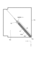
図1は、本実施例の画像形成装置1の外観構成を説明するための模式的な斜視図であり、図2は、画像形成装置1の内部構成を示す概略的な断面図である。本実施例の画像形成装置1は、複数の画像形成部PY、PM、PC、PKを有する、いわゆるタンデム型の画像形成装置である。第1の画像形成部PYはイエロー(Y)、第2の画像形成部PMはマゼンタ(M)、第3の画像形成部PCはシアン(C)、第4の画像形成部PKはブラック(Bk)の各色のトナーによって画像を形成する。
Example 1
[Configuration of Image Forming Apparatus]
Fig. 1 is a schematic perspective view for explaining the external configuration of the
また、画像形成装置1はプロセスカートリッジ方式であり、複数の画像形成部PY、PM、PC、PKは、それぞれプロセスカートリッジとして構成され、装置本体2に対して着脱可能である。なお、各プロセスカートリッジの取り外し又は取り付けは、画像形成装置1に設けられる開閉ドア3を開いた状態で行われる。図2に示すように、これら4つの画像形成部は一定の間隔をおいて一列に配置されており、各画像形成部の構成は収容するトナーの色を除いて実質的に共通である部分が多い。したがって、以下の説明において、特に区別を要しない場合は、いずれかの色用の要素であることを示す符号の末尾Y,M,C,Kは省略して、当該要素について統括的に説明する。
The
また、以下の説明においては、画像形成装置1に関して、開閉ドア3を設けた側を正面(前面)、正面と反対側の面を背面(後面)とする。また、画像形成装置1を正面から見て右側を駆動側、左側を非駆動側と称す。なお、図面において、装置本体2の背面から正面に向かう方向をX軸方向、本体非駆動側から駆動側に向かう方向をY軸方向、装置本体2の底面から上面に向かう方向をZ軸方向、とそれぞれ定義する。
In the following description, the side of the
図2に示すように、各画像形成部Pは、装置本体2の底面に対して水平に並んで配置されている。画像形成部Pは、電子写真プロセス機構を有しており、装置本体2に設けられた不図示のカートリッジ駆動伝達部から回転駆動力が伝達される。画像形成部Pは、トナー像を担持する像担持体としての感光ドラム40と、帯電手段(不図示)と、現像手段(不図示)と、を有する。
As shown in FIG. 2, each image forming unit P is arranged horizontally on the bottom surface of the device
そして、Z軸方向に関する画像形成部Pの上方には、露光手段LSが設けられており、露光手段LSは、不図示のコントローラが受信した画像情報に対応してレーザ光を出力する。露光手段LSから出力されたレーザ光は、画像形成部Pの露光窓部を通過して感光ドラム40の表面を走査露光する。 An exposure means LS is provided above the image forming unit P in the Z-axis direction, and the exposure means LS outputs laser light corresponding to image information received by a controller (not shown). The laser light output from the exposure means LS passes through an exposure window portion of the image forming unit P and scans and exposes the surface of the photosensitive drum 40.
また、Z軸方向に関する画像形成部Pの下方には、転写手段11が設けられている。転写手段11は、移動可能な無端状の中間転写ベルト12と、一次転写ローラ16と、駆動ローラ13と、張架ローラ17と、張架ローラ15と、回収手段19と、収容容器18と、を有する。駆動ローラ13は、駆動力を受けて回転することで中間転写ベルト12を図示矢印B方向に移動させ、張架ローラ17及び張架ローラ15と共に中間転写ベルト12を張架する。回収手段19は、中間転写ベルト12に残留したトナーを回収し、回収手段19によって回収されたトナーは、中間転写ベルト12の内周面によって構成される領域内に設けられる収容容器18に収容される。
In addition, below the image forming unit P in the Z-axis direction, a
一次転写ローラ16は、感光ドラム40に担持されたトナー像を、感光ドラム40から中間転写ベルト12に転写するための転写手段であり、中間転写ベルト12の内周面に接触している。各一次転写ローラ16Y、16M、16C、16Kは、中間転写ベルト12を介して各感光ドラム40Y、40M、40C、40Kに対応して設けられている。各一次転写ローラ16は、図示矢印B方向と直交する方向、即ち、Y軸方向に延在して設けられており、中間転写ベルト12を各感光ドラム40に向けて付勢し、感光ドラム40と中間転写ベルト12とが接触する一次転写部を形成する。
The primary transfer roller 16 is a transfer means for transferring the toner image carried on the photosensitive drum 40 from the photosensitive drum 40 to the
本実施例において、各一次転写ローラ16は、弾性層を有さない金属ローラである。金属ローラによって構成される一次転写ローラは、コスト面が安価である一方で、硬度が高いために対向部材を摩耗させてしまう恐れがある。そこで、本実施例の構成においては、図2に示すように、各感光ドラム40と中間転写ベルト12とが接触する各一次転写部の位置に対して、各一次転写ローラ16をずらして配置している。より詳細には、中間転写ベルト12の移動方向に関して、各一次転写ローラ16を、各一次転写部の位置よりも下流側にシフトさせて配置している。なお、各一次転写ローラ16は、各一次転写部の位置よりも上流側にシフトさせてもよい。
In this embodiment, each primary transfer roller 16 is a metal roller that does not have an elastic layer. While primary transfer rollers made of metal rollers are inexpensive, they have a high hardness and may wear out the opposing members. Therefore, in the configuration of this embodiment, as shown in FIG. 2, each primary transfer roller 16 is positioned with a shift with respect to the position of each primary transfer section where each photosensitive drum 40 and the
回収手段19は、枠体19aと、枠体19aの内部に設けられ、Y軸方向に関して延在するクリーニングブレード19b(回収部材)と、を有する。クリーニングブレード19bは、中間転写ベルト12の移動方向に対向するカウンター方向で中間転写ベルト12の外周面に当接するように配置されており、中間転写ベルト12に残留したトナーを枠体19aに回収する。
The recovery means 19 has a
中間転写ベルト12を介して、駆動ローラ13(駆動回転体)と対向する位置には二次転写ローラ14が配置されており、二次転写ローラ14と中間転写ベルト12とが当接する位置に二次転写部が形成されている。また、転写材Sの搬送方向に関して、二次転写部よりも上流側には、転写材Sを収容する給紙カセット51と、給紙カセット51から二次転写部に向かって転写材Sを給送する給紙ローラ52と、を有する給送手段50が設けられている。
A
転写材Sの移動方向に関して、二次転写部よりも下流側には、転写材Sにトナー像を定着する定着手段21と、トナー像が定着された転写材Sを装置本体2から排出する排出ローラ対22と、が設けられている。排出ローラ対22によって装置本体2から排出された転写材Sは、排紙トレイ23に積載される。
In terms of the direction of movement of the transfer material S, downstream of the secondary transfer section are provided
[画像形成動作]
次に本発明の画像形成装置1の画像形成動作を説明する。コントローラ等の制御手段(不図示)が画像信号を受信することによって画像形成動作が開始され、感光ドラム40及び駆動ローラ13等は不図示の駆動源からの駆動力によって所定の周速度(プロセススピード)で回転を始める。
[Image Forming Operation]
Next, a description will be given of an image forming operation of the
感光ドラム40は、不図示の帯電手段によって、その表面をトナーの正規の帯電極性(本実施例においては負極性)と同極性に一様に帯電される。その後、露光手段LSからレーザ光を照射されることによって画像情報に従った静電潜像が形成される。そして、不図示の現像手段に収容されたトナーによって感光ドラム40に形成された静電潜像が現像され、感光ドラム40の表面に画像情報に応じたトナー像が担持される。この時、各感光ドラム40Y、40M、40C、40Kに、イエロー、マゼンタ、シアン、ブラックの各色の画像成分に応じたトナー像が担持される。
The surface of the photosensitive drum 40 is uniformly charged by a charging means (not shown) to the same polarity as the normal charging polarity of the toner (negative polarity in this embodiment). After that, an electrostatic latent image according to the image information is formed by irradiating it with laser light from an exposure means LS. The electrostatic latent image formed on the photosensitive drum 40 is then developed by the toner contained in a developing means (not shown), and a toner image according to the image information is carried on the surface of the photosensitive drum 40. At this time, toner images according to the image components of each color of yellow, magenta, cyan, and black are carried on each of the
その後、各感光ドラム40に担持された各色のトナー像は、各感光ドラム40の回転に伴って各一次転写部に到達する。そして、各一次転写ローラ16に不図示の電源から電圧を印加することによって、各感光ドラム40に担持された各色のトナー像は各一次転写部において中間転写ベルト12に順次重ねて一次転写される。これにより、中間転写ベルト12には、目的のカラー画像に対応した4色のトナー像が形成される。
Then, the toner images of each color carried on each photosensitive drum 40 reach the respective primary transfer sections as each photosensitive drum 40 rotates. Then, by applying a voltage to each primary transfer roller 16 from a power source (not shown), the toner images of each color carried on each photosensitive drum 40 are sequentially superimposed and primarily transferred onto the
その後、中間転写ベルト12に担持された4色のトナー像は、中間転写ベルト12の移動に伴って二次転写部に到達し、二次転写部を通過する過程で、紙やOHPシートなどの転写材Sの表面に一括で二次転写される。この時、二次転写ローラ14には不図示の二次転写電源からトナーの正規の帯電極性とは逆極性の電圧が印加される。
The four-color toner image carried by the
給紙カセット51に収容された転写材Sは、所定のタイミングで給紙ローラ52によって給紙カセット51から給送され、二次転写部に向けて搬送される。そして、二次転写部において4色のトナー像を転写された転写材Sは、定着手段21において加熱および加圧されることにより、4色のトナーが溶融混色して転写材Sに定着される。その後、転写材Sは排出ローラ対22によって装置本体2から排出され、積載部としての排紙トレイ23に積載される。
The transfer material S stored in the
二次転写後に中間転写ベルト12に残留したトナー(以下、転写残トナーと称する)は、中間転写ベルト12を介して駆動ローラ13に対向して設けられた回収手段19によって、中間転写ベルト12の表面から除去される。本実施例の画像形成装置1においては、以上の動作により、フルカラーのプリント画像が形成される。
Toner remaining on the
なお、本実施例の画像形成装置1には、画像形成装置の各部の動作の制御を行うための不図示のコントローラと、各種の制御情報が格納された記憶手段としてのメモリ(不図示)などが搭載されている。コントローラは、転写材Sの搬送に関する制御や、中間転写ベルト12、及びプロセスカートリッジとしての各画像形成部Pの駆動に関する制御、画像形成に関する制御、更には故障検知に関する制御などを実行する。
The
[回収手段による転写残トナーの回収]
二次転写後に中間転写ベルト12に残留した転写残トナーは、クリーニングブレード19bで物理的に中間転写ベルト12から掻きとられ、回収手段19の枠体19aに一時的に収容される。以下、回収手段19による転写残トナーの回収工程について説明する。
[Recovery of Residual Toner After Transfer by Recovery Unit]
Residual toner remaining on the
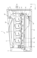
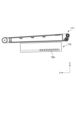
図3(a)は、中間転写ベルト12を除去した状態の転写手段11の構成を示す模式的な斜視図である。図3(a)における矢印は、クリーニングブレード19bによって回収された転写残廃トナーの搬送経路を示している。なお、回収手段19の内部構成を説明するために、図3においては、枠体19aを省略して図示していない。回収手段19は、枠体19aの内部に、クリーニングブレード19bと、クリーニングブレード19bによって中間転写ベルト12から掻きとられた転写残トナーを搬送する搬送部材19cと、を有する。搬送部材19cは、回転軸の軸線方向に螺旋状の搬送部C1を有し、不図示の駆動源からの駆動力を受けて回転することにより、図示矢印Sa方向(Y軸方向)に転写残トナーを搬送する。
Figure 3(a) is a schematic perspective view showing the configuration of the transfer means 11 with the
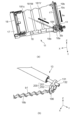
その後、枠体19a内において図示矢印Sa方向に搬送された転写残トナーは、搬送部材19cによるトナー搬送方向に関する下流端部側、言い換えると、転写手段11の駆動側端部に隣接して設けられた搬送路184において図示矢印Sb方向に搬送される。搬送路184は、収容容器18の流入口18aと連結されている。また、収容容器18の内部には、一端側が流入口18aの近傍に配置された搬送部材18bが設けられている。搬送部材18bは、回転軸の軸線方向に螺旋状の搬送部b1を有し、回転することによって、流入口18aに到達した転写残トナーを図示矢印Sc方向に搬送する。
Then, the transfer residual toner transported in the
図3(b)は、転写手段11の駆動側端部に設けられる、駆動ローラ13及び搬送部材18bに駆動を伝達する機構を説明する模式図である。図3(b)に示すように、本実施例においては、搬送部材18bと駆動ローラ13は、ギア部201とギア部201とを有する駆動連結部材200によって、駆動が連結されている。より詳細には、駆動ローラ13は駆動側端部にギア131を有し、搬送部材18bは駆動側端部にギア186を有しており、ギア131はギア部201と係合し、ギア186はギア部202と係合している。駆動ローラ13は、軸部132を有しており、軸部132が不図示の駆動源からの駆動力を受けて回転すると、ギア131も回転する。そして、ギア131の回転によって駆動連結部材200を介して、駆動ローラ13の回転力がギア186に伝達され、搬送部材18bが回転する。
Figure 3(b) is a schematic diagram illustrating a mechanism for transmitting drive to the
[転写手段及び収容容器の構成]
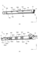
図4(a)は、転写手段11を側面(XZ面)から見た際の模式的な断面図である。また、図4(b)は、転写手段11の、駆動側の構成を説明するための模式的な側面(XZ面)図である。ここで、図4(b)においては、中間転写ベルト12の図示を省略している。図4(a)、(b)に示すように、本実施例の収容容器18は、転写手段11の、中間転写ベルト12の内周面によって構成される領域内に設けられている。また、転写手段11及び収容容器18の底面は、画像形成装置1の底面に対して略水平となるように配置されている。
[Configuration of transfer means and storage container]
Fig. 4(a) is a schematic cross-sectional view of the transfer means 11 as viewed from the side (XZ plane). Fig. 4(b) is a schematic side (XZ plane) view for explaining the configuration of the drive side of the transfer means 11. Here, in Fig. 4(b), the
本実施例における収容容器18は、重力方向に関して、収容容器18の上面を構成する上側部材18cと、収容容器18の底面を構成する下側部材18dと、を有し、上側部材18cと下側部材18dによって枠体が構成されている。より詳細には、上側部材18cは、一次転写ローラ16が設けられている側に配置されており、下側枠体18dは、転写手段11において画像形成装置1の底面側に近い位置に配置されている。また、上側部材18cと下側部材18dは、XY平面上において略長方形形状で構成された上側部材18c及び下側部材18dの端部4辺を超音波溶着することによって接合されることで、収容容器18の枠体を構成する。なお、上側部材18cと下側部材18dの固定は超音波溶着に限定されるものではなく、収容容器18から転写残トナーが漏れない構成であれば、熱溶着などの他の溶着、締結や接着など手段を用いてもよい。
The
図4(a)に示すように、上側部材18cの、一次転写ローラ16Y,16M,16Cと対向する部分は、各一次転写ローラ16が設けられている位置から離れる方向、即ち、下側部材18dに向かう方向に退避して構成されている。より詳細には、上側部材18aの、各一次転写ローラ16が設けられている位置には、各一次転写ローラ16の延在方向に沿って、溝部181Y、181M、181Cが形成されている。この構成により、収容容器18は、各一次転写ローラ16の回転を規制することなく、収容容器18のトナー収容容量を十分に確保することが可能である。また、上側部材18cに溝部181Y、181M、181Cを形成することにより、収容容器18の強度を向上させて枠体の変形を抑制することが可能である。
As shown in FIG. 4A, the portion of the
図4(b)に示すように、一次転写ローラ16Y、16M、16C、16Kは、各一次転写ローラ16の延在方向に関する端部側を、それぞれ、一次転写軸受162Y、162M、162C、162Kによって回転可能に支持されている。一次転写軸受162Y、162M、162C、162Kは、上側部材18cに一端側を固定されたバネ163Y、163M、163C、163Kによって+Z方向にそれぞれ付勢されており、Z軸方向に移動可能な状態で上側部材18cに支持されている。
As shown in FIG. 4B, the
本実施例の構成においては、各一次転写ローラ16は、中間転写ベルト12から離間するための機構を有さない。即ち、各一次転写ローラ16が各バネ163(付勢部材)によって付勢されることで、中間転写ベルト12と各感光ドラム40は常に接触した状態を形成する。このように、転写手段11に、各一次転写ローラ16を中間転写ベルト12から離間する機構を設けないことにより、転写手段11の内部の領域を、最大限に収容容器18の容量にあてることが可能となる。
In the configuration of this embodiment, each primary transfer roller 16 does not have a mechanism for separating it from the
また、張架ローラ17は、軸受17aを介してテンションバネ173によって+X方向に付勢されることで、中間転写ベルト12を張架する。ここで、テンションバネ173の一端側は軸受17aを付勢しており、他端側は上側部材18cによって支持されている。本実施例の構成においては、軸受17aをテンションバネ173の付勢力に抗して移動させることで、張架ローラ17による中間転写ベルト12の張架状態を解除することが可能である。
The
[収容容器への転写残トナーの充填]
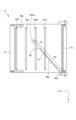
図5は、中間転写ベルト12の移動方向及び一次転写ローラ16の延在方向と直交する方向から水平面(XY平面)に投影して見た際の、転写手段11及び収容容器18の概略的な模式図である。図5においては、収容容器18の構成を説明するために、転写手段11における中間転写ベルト12の図示を省略している。搬送路184を介して流入口18aから収容容器18に流入する転写残トナーは、搬送部材18bによってXY平面における収容容器18の略中央部へ搬送される。
[Filling of Residual Toner into Storage Container]
5 is a schematic diagram of the transfer means 11 and the
図5に示すように、搬送部材18bは、搬送部材18bの回転軸線方向に関して、一端部が流入口18a側に設けられており、他端部が軸受183a(支持部)に支持されている。軸受183aは、収容容器18の下側部材18dに設けられており、搬送部材18bを回転可能に支持する。搬送部材18bは、回転軸線方向に関して、搬送部b1が設けられている領域Sbと、搬送部b1が設けられておらず、軸部のみで構成される領域Srと、を有する。領域Sbと領域Srとの境には、回転軸線方向に関して、流入口18aとは反対側に設けられる搬送部b1の端部Eb(末端部)が設けられている。ここで、搬送部材18bの回転軸線方向は、図5にも示すように、中間転写ベルト12の移動方向であるX軸方向とも一次転写ローラ16の延在方向であるY軸方向とも直交しない方向であって、X軸方向及びY軸方向と交差する方向である。
As shown in FIG. 5, the conveying
XY平面に投影して収容容器18を見た際に、端部Ebは、中間転写ベルト12の移動方向であるX軸方向に関して、一次転写ローラ16Yよりも下流側であって、かつ、一次転写ローラ16Kよりも上流側に設けられている。言い換えると、端部Ebは、X軸方向に関して、一次転写ローラ16Yと一次転写ローラ16Kとの間、本実施例におけるより詳細な位置としては、一次転写ローラ16Yと一次転写ローラ16Mとの間にあたる、収容容器18の中央領域Rcに設けられている。中央領域Rcに関しては後に詳細に説明する。本実施例においては、この構成により、流入口18aから流入した転写残トナーは、収容容器18の内部において、搬送部b1によって流入口18aから端部Ebに向かって搬送され、領域Sbの終端部である、収容容器18の略中央部で堆積する。
When the
ここで、搬送部材18bの回転軸線方向に関して、端部Ebに近接して軸受183aを設けて搬送部材18bの他端部を支持すると、搬送部材18bによるトナー搬送力を強く受ける領域付近で軸受183aと搬送部材18bの回転摺動が生じることとなる。このような構成、即ち領域Srを設けない構成とした場合、回転摺動が生じる位置においてトナーが固着することによって、搬送部材18bによる転写残トナーの搬送安定性の低下が起きるおそれがある。
Here, if bearing 183a is provided near end Eb in the direction of the rotation axis of
また、詳細は後述するが、本実施例の構成によれば、搬送部材18bによって搬送された転写残トナーが、端部Ebにおいて同心円形状に拡散しながら収容容器18に充填されていく。しかしながら、端部Ebに近接して軸受け183aを設けてしまうと、転写残トナーが拡散する際に同心円形状の不均一化が生じてしまうおそれがある。よって、図5に示すように、領域Sbと軸受183aの間に、螺旋状の搬送部b1を有さない領域Srを設けることが望ましい。ただし、回転軸線方向における領域Srの長さは任意に設定されるものであって、図5に示すように、収容容器18のXY平面上、一次転写ローラ16M付近に搬送部材18bの終端を設ける構成に限らない。例えば、領域Srを図5よりもさらに長く設け、XY平面上において、搬送部材18bの回転軸線方向に関する仮想線と収容容器18bとが交差する壁面18e付近に搬送部材18bの終端を設ける構成としてもよい。
In addition, although details will be described later, according to the configuration of this embodiment, the transfer residual toner transported by the
次に、図6(a)~図6(d)を用いて、本実施例の収容容器18における、転写残トナーの充填について説明する。図6(a)は、収容容器18の流入口18aに転写残トナーが到達する前の収容容器18を、XY平面に投影して見た模式図である。図6(b)、(c)、(d)は、それぞれ、搬送部材18bの回転により流入口18aから端部Ebに向かって搬送される転写残トナーが収容容器18において充填されていく様子を説明する模式図である。
Next, the filling of the
本実施例の構成においては、図6(a)に示した収容容器18に転写残トナーが収容されていない状態をスタートとして、転写残トナーの充填が開始される。流入口18aに転写残トナーが到達すると、搬送部材18bの回転によって、転写残トナーが端部Ebに向かって搬送され、図6(b)の状態となる。そして、図6(b)に示すように、搬送部材18bの回転によって収容容器18の中央領域Rcに設けられた端部Ebに向かって搬送された転写残トナーは、端部Ebを中心として堆積し、同心円状に広がりながら収容容器18内に充填される。
In the configuration of this embodiment, the
ここで、図6(a)及び(b)における一点鎖線は、中間転写ベルト12の移動方向であるX軸方向と、中間転写ベルト12の幅方向であるY軸方向のそれぞれに関して収容容器18を三等分した線である。このように区分けすることによって、図6(a)及び(b)に示されるように、収容容器18をXY平面上において9つの領域に略等分割することができる。本実施例においては、搬送部材18bの端部Ebを、9つに等分割された領域のうちの中央領域Rc内に配置している。ここにおける中央領域Rcは、X軸方向に関して収容容器18を三等分した真ん中の領域と、Y軸方向に関して収容容器18を三等分した真ん中の領域とが重なる領域である。端部Ebの配置に関して後に詳細に説明する。
The dashed lines in Figures 6(a) and (b) are lines dividing the
図6(c)に示すように、引き続き、搬送部材18bの回転により転写残トナーが端部Ebに向けて搬送され、同心円形状が拡大することで充填が継続される。そして、図6(c)からさらに転写残トナーの充填が行われると、図6(d)に示すように、同心円状に広がった転写残トナーが略長方形形状の上側部材18cの4つの各壁面に到達し、収容容器18内が転写残トナーで満たされる。なお、本実施例の構成においては、収容容器18の底面が画像形成装置1の底面に対して略水平な構成、言い換えると、下側部材18dが画像形成装置1の接地面に対して略水平な形状である。この構成によれば、収容容器18において同心円形状で拡散する転写残トナーが収容容器18の4つの各壁面へほぼ同時に到達するため、充填効率上望ましい。
As shown in FIG. 6(c), the transfer residual toner continues to be transported toward the end Eb by the rotation of the
図7は、本実施例の比較例の構成であり、搬送部材18bxの領域Sbxの端部Ebxの位置を、本実施例の端部Ebが設けられている位置よりも、回転軸線方向に関する流入口18a側に配置した構成である。言い換えると、比較例においては、端部Ebxは中央領域Rcに配置されていない。また、この比較例の構成においては、図示はしていないが、端部Ebxは、中間転写ベルト12の移動方向であるX軸方向に関して一次転写ローラ16Yよりも上流側の位置であり、一次転写ローラ16Kよりも駆動ローラ13に近い位置に設けられている。以下の説明において、比較例と本実施例とで構成が実質的に同一の部分に関しては、同一の符号を付して説明を省略する。
Figure 7 shows a comparative example of the present embodiment, in which the position of the end Ebx of the region Sbx of the transport member 18bx is located closer to the
図7に示すように、比較例の構成においても、本実施例と同様に、収容容器18内で領域Sbxの終端部、即ち、搬送部材18bxの端部Ebxを中心として同心円状に転写残トナーが拡散される。しかしながら、比較例の構成においては、端部Ebxが一次転写ローラ16Yよりも上流側、即ち、収容容器18の略中央よりも流入口18aに位置することから、拡散した転写残トナーは上側部材18cの流入口18a側の2つの壁面に先に到達する。そして図7の状態から継続して転写残トナー搬送をした場合、転写残トナーの同心円形状の一部が壁面に到達していることから、更なる同心円形状の拡大化が困難となり、搬送部材18bの回転トルクの上昇や、収容容器18の変形が発生するおそれがある。
As shown in FIG. 7, in the comparative example, the transfer residual toner is diffused in a concentric shape around the end of the region Sbx in the
このように、比較例の構成においても、1本の搬送部材18bによって同心円状に転写残トナーを拡散させることは可能である。しかし、図7の状態からさらに継続して搬送部材18bxの回転による転写残トナーの搬送を実施しても、転写残トナーはこれ以上同心円状には拡散していかないため、比較例の構成は本実施例の構成よりも転写残トナーの充填効率が低い。また、中央領域Rcの外側であって、搬送部材18bの回転軸線方向に関する流入口18aとは反対側の領域に端部Ebを設けた場合も、同様の理由により充填効率が低くなる。以上のことから、本実施例においては、転写残トナーを収容容器18に効率よく充填するために、端部Ebを収容容器18の中央領域Rcに設けている。
In this way, even in the configuration of the comparative example, it is possible to diffuse the transfer residual toner in a concentric shape by a
ここで、本実施例の転写手段11と収容容器18の配置の関係から見ると、収容容器18の中央領域Rcは、図5、図6(a)で示したように、中間転写ベルト12の移動方向に関して一次転写ローラ16Yよりも下流側であって、一次転写ローラ16Cよりも上流側にあたる領域である。以上の説明のように、中央領域Rcに端部Ebを設けることによって転写残トナーの充填率を向上させることが可能であるが、中央領域Rcの中でより中心部に近い位置に端部Ebを設けることで、更なる充填率の向上をのぞめる。即ち、本実施例の画像形成装置1の構成における各一次転写ローラ16の配置に関していえば、端部Ebを、中間転写ベルト12の移動方向に関して一次転写ローラ16Yと一次転写ローラ16Mとの間にあたる中央領域Rc内に設けることで、より充填効率の向上を達成することが可能となる。
In terms of the arrangement of the transfer means 11 and the
本実施例においては、転写手段11における中間転写ベルト12の内周面によって構成される領域内に配置した収容容器18の中央領域Rcが、一次転写ローラ16Yと16Mの間の位置に対応している。ここで、中間転写ベルト12の移動方向(X軸方向)に関する各一次転写ローラ16の配置は、各感光ドラム40の位置に応じて適宜設定されるものである。また、X軸方向に関する各感光ドラム40の配置は、画像形成装置1における各種部材の配置に基づいて適宜設定されるものである。即ち、X軸方向に関して、各一次転写ローラ16位置は本実施例において図示した位置よりも多少異なる場合がある。
In this embodiment, the central region Rc of the
この場合、図7に示すように、流入口18aに近い位置よりも、流入口18aと壁面18eとを結ぶ直線(搬送部材18bの回転軸線方向に関する仮想線)の中間点AEに近い位置が中央領域Rcに対応することが多い。したがって、中間点AEの近傍に端部Ebを配置することで、本実施例と同様の効果を得ることができる。搬送部材18bの回転軸線方向に関する流入口18aとは反対側の領域に関しても、同様に、壁面18eよりも中間点AEに近い位置に端部Ebを配置することで、本実施例と同様の効果を得ることができる。
In this case, as shown in FIG. 7, the central region Rc is often closer to the midpoint AE of the straight line (a virtual line in the direction of the rotation axis of the conveying
以上説明したように、本実施例は、収容容器18の内部に1本の搬送部材18bを設け、搬送部材18bによって搬送される転写残トナーを収容容器18内で同心円状に充填する構成を有する。この構成によれば、1本の搬送部材18bのみでも効率よく転写残トナーを充填できるため、収容容器18の内部に複数の搬送部材を設ける必要がなく、収容容器の容積に対するトナーの充填率を向上させることが可能である。また、複数の搬送部材を設けなくてもよいことから、画像形成装置のコストダウンを達成することも可能となる。
As described above, this embodiment has a configuration in which one
さらに、従来の、収容容器内に複数の搬送部材を設ける構成においては、転写残トナーが介在する収容容器の内部空間にて複数の搬送部材間で回転動作の連結が必要であった。この場合、回転動作の連結部に転写残トナーが付着したときに発生する異音や振動による動作不良、回転動作の連結部において発生する摩擦熱に伴うトナー融着による部品破損等に対処可能な構成を採用する必要があった。しかしながら、本実施例の構成によれば、収容容器内において複数の部材間駆動連結を行う構成を採用する必要がないことから、前述のような課題を考慮する必要がない。その結果、より簡易的な構成で、安定的に収容容器18に転写残トナーを充填することが可能である。
Furthermore, in the conventional configuration in which multiple transport members are provided in the storage container, it was necessary to couple the rotational motion between the multiple transport members in the internal space of the storage container where the transfer residual toner is present. In this case, it was necessary to adopt a configuration that could deal with malfunctions caused by abnormal noise and vibrations that occur when transfer residual toner adheres to the connection part of the rotational motion, and damage to parts due to toner fusion caused by frictional heat generated at the connection part of the rotational motion. However, according to the configuration of this embodiment, since it is not necessary to adopt a configuration for driving and coupling multiple members within the storage container, there is no need to consider the above-mentioned issues. As a result, it is possible to stably fill the
また、本実施例のように、転写手段11の内部に収容容器18を設ける構成においては、部品寿命などによって転写手段11を交換する際に、転写手段11を交換する動作に伴って収容容器18も交換することが可能である。これにより、ユーザやサービスマンによる交換作業の手間を減らし、ユーザビリティの向上を図ることができる。さらに、本実施例構成によれば、転写手段11の内部に収容容器18を設けることで、従来収容容器を配置していたスペースを削減して画像形成装置1の小型化を達成することが可能である。
In addition, in a configuration in which a
本実施例においては、各一次転写ローラ16として、より安価な金属ローラを用いる構成について説明したが、これに限らない。転写部材として、導電弾性層を有するローラ部材や、導電性のシート部材、導電性のブラシ部材などを用いる事も可能である。また、導電弾性層を有するローラなどの前述の転写部材を用いる場合、本実施例のように、各一次転写部に対して転写部材をシフトさせて配置してもよく、各一次転写部材の直下に配置してもよい。 In this embodiment, a configuration in which a less expensive metal roller is used as each primary transfer roller 16 has been described, but this is not limited to this. It is also possible to use a roller member having a conductive elastic layer, a conductive sheet member, a conductive brush member, or the like as the transfer member. Furthermore, when using the aforementioned transfer members such as rollers having a conductive elastic layer, the transfer members may be shifted and positioned with respect to each primary transfer section, as in this embodiment, or may be positioned directly below each primary transfer member.
(変形例1)
図8は、本実施例の変形例1として、収容容器18内において、搬送部材18bの両側を囲うように、搬送ガイド183b(ガイド部)を下側部材18dに設ける構成について説明する模式図である。図8は、図6(a)~(b)と同様、収容容器18をXY平面に投影して見た模式図であり、以下の説明において、実施例1と変形例1とで実質的に共通する構成に関しては、同一の符号を付して説明を省略する。
(Variation 1)
Fig. 8 is a schematic diagram for explaining a configuration in which, as a first modification of this embodiment, a
図8に示すように、変形例1においては、搬送ガイド183bを設けたことにより、流入口18aから収容容器18の中央領域Rcに向かって、転写残トナーを搬送ガイド183bより外側に漏らすことなく搬送することが可能となる。これにより、転写残トナーが収容容器18の略中央部に到達するまでのトナー搬送ロスを小さくし、より効率よく転写残トナーを充填することが可能となる。ここで、搬送ガイド183bの内側とは、搬送ガイド183bが搬送部材18bと面している側を指しており、搬送ガイド183bの外側はその内側とは反対側を指す。
As shown in FIG. 8, in the first modified example, the
なお、搬送ガイド183bの形状は図8に示す形状に限らない。搬送ガイド183bの外側に転写残トナーが漏れない構成であれば、例えば、搬送部材18bのZ方向上面を覆うようなトンネル形状としても良い。また、搬送ガイド183bの外側への転写残トナーの漏れ量を最小限にするため、本変形例においては搬送ガイド183bを、搬送部材18bの回転軸線方向に関して流入口18aから端部Ebまでの領域Sb内全域に設けたが、これに限らない。領域Sb内において、流入口18a側のみに設けてもよく、搬送ガイド183bを回転軸線方向に関して連続して設けずに一部領域ずつ複数に分割して設けてもよい。
The shape of the
(変形例2)
図9は、本実施例の変形例2として、収容容器18の下側部材18dに放射状のリブ183cを設ける構成について説明する模式図である。図9は、図6(a)~(b)と同様、収容容器18をXY平面に投影して見た模式図であり、以下の説明において、実施例1と変形例2とで実質的に共通する構成に関しては、同一の符号を付して説明を省略する。
図9に示すように、変形例2は、下側部材18dにおいて、収容容器18の中央領域Rcに設けられる端部Ebの近傍を起点として、放射状にリブ183cを設けている。リブ183cを設けたことによって、収容容器18の強度を向上させることができ、転写残トナーの充填時の重量増加による下側部材18dの変形の低減することか可能である。これにより、転写手段11の内部に収容容器18を設ける構成において、転写残トナーの充填に伴って収容容器18が-Z方向に変形し、下側部材18dの一部が中間転写ベルト12と接触してしまうことを抑制することが可能である。
(Variation 2)
Fig. 9 is a schematic diagram illustrating a configuration in which
9, in the second modification,
また、本変形例の構成によれば、同心円状に充填される転写残トナーの進展方向と放射状のリブ183cの長手方向が略一致しているため、放射状のリブ183cが転写残トナーの充填を妨げない。さらに、放射状のリブ183cは、転写残トナーが同心円状に拡大する際のガイドとなることで、転写残トナーの各方向への進展をより均一化させて、転写残トナーを収容容器18に充填する際の効率を向上させることが可能である。なお、リブ183cの長さ、高さ、本数等は、本変形例の図9に示した構成に限らず適宜設定してよい。下側部材18dの強度向上の観点においては、リブ183cの長さは収容容器18の各壁面まで延長されている方がより望ましい。
In addition, according to the configuration of this modified example, the direction of progression of the transfer residual toner filled concentrically is approximately the same as the longitudinal direction of the
(変形例3)
図10(a)は、本実施例の変形例3として、収容容器18の内部において、下側部材18dと上側部材18cとの間に柱状部材182aを設ける構成について説明する模式図である。また、図10(b)は、図6(a)~(d)と同様に、本変形例の収容容器18を、XY平面に投影して見た模式図である。以下の説明において、実施例1と変形例3とで実質的に共通する構成に関しては、同一の符号を付して説明を省略する。
(Variation 3)
Fig. 10(a) is a schematic diagram for explaining a configuration in which a
図10(a)に示すように、本変形例においては、中央領域Rcの近傍に柱状部材182aを設けている。より詳細には、上側部材18cの略中央部の近傍位置に柱状部材182aを設け、上側部材18cと下側部材18dを連結する。この構成により、転写残トナーを充填すする際の、収容容器18のZ軸方向の変形を低減し、上側部材18c及び下側部材18dが中間転写ベルト12と接触してしまうことを抑制することが可能である。
また、図10(b)に示すように、本変形例の構成によれば、柱状部材182cを、端部Ebの近傍において端部Ebから一定の距離を設けて配置している。これにより、柱状部材182cは、転写残トナーの充填を妨げることなく、収容容器18内で転写残トナーの堆積が開始する位置を支持することが可能となり、下側部材18dの変形を効率的に抑制できる。柱状部材182aは、同心円状に拡散する転写残トナーの進展の妨げとならない形状が望ましく、その一例として、図10(b)に示すように、柱状部材182aの断面が転写残トナーの放射状の進展方向と略一致する向きの流線形状となる構成が挙げられる。
10A, in this modification, a
10B, according to the configuration of this modification, the columnar member 182c is disposed at a certain distance from the end Eb in the vicinity of the end Eb. This allows the columnar member 182c to support the position where the accumulation of the transfer residual toner starts in the
図10(b)に示すように、本変形例においては、柱状部材182aを端部Ebの近傍に4点設けている。しかし、柱状部材182aの配置数はこれに限らない。また、本変形例においては、柱状部材182aと下側部材18dとをビス締結によって固定しているが、これに限らず、熱溶着・超音波溶着などの溶着や接着などの手段を用いて上側部材18cに設けた柱状部材182aを下側部材18dに固定してもよい。さらに、本変形例においては、柱状部材182aを上側部材18cに設けているが、これに限らず、柱状部材182aを下側部材18dに設け、上側部材18cに対して前述の固定手段を用いて固定してもよい。
As shown in FIG. 10(b), in this modified example, four
(実施例2)
実施例1においては、転写手段11の内部、即ち、中間転写ベルト12の内周面によって構成される領域内に転写残トナーを収容する収容容器18を設ける構成について説明した。これに対し、実施例2は、転写残トナーを収容する収容容器118を、中間転写ベルト12の内周面の内側ではなく、転写手段11の外部に配置する点で実施例1と異なる。なお、実施例2においては、収容容器118の配置位置を除くその他の画像形成装置の構成は実施例1と実質同一である。したがって、以下、実施例1と共通する部分に関しては実施例1と同一の符号を付して説明を省略する。
Example 2
In the first embodiment, a configuration has been described in which a
図11は、本実施例の収容容器118の配置について説明する模式図である。図11に示すように、収容容器118は、Z軸方向に関して、転写手段11の底面よりも下に配置されている。このように、収容容器118を転写手段11の外部に設けることで、実施例1において説明したような転写残トナーの充填性を維持しつつ、収容容器118のみを画像形成装置1に対して着脱することが可能となる。即ち、本実施例の構成においては、転写手段11の部品寿命に関係なく、収容容器118を交換することが可能である。
Figure 11 is a schematic diagram illustrating the arrangement of the
なお、以上の実施例においては、中間転写ベルト12を用いた中間転写方式の画像形成装置1について説明したが、これに限らない。転写材Pを搬送する搬送ベルトを有する直接転写方式の画像形成装置においても、本実施例にて説明した転写残トナー回収構成を用いることで、本実施例と同様の効果を得ることが可能である。
In the above embodiment, the
11 転写手段
12 中間転写ベルト
16 一次転写ローラ
18 収容容器
18a 流入口
18b 搬送部材
19a クリーニングブレード
REFERENCE SIGNS
Claims (11)
前記転写手段は、
移動可能であって、前記像担持体と接触する無端状のベルトと、
第1の転写部材及び第2の転写部材及び第3の転写部材を含む複数の転写部材と、
前記ベルトに当接し、前記ベルトに残留したトナーを回収するための回収部材と、
前記ベルトの内周面によって構成される領域内に配置された収容容器であって、前記回収部材によって回収されたトナーが流入する流入口を備える収容容器と、
回転することによって、前記収容容器内において前記流入口からトナーを搬送する単一の搬送部材と、を備え、
前記搬送部材は前記搬送部材の回転軸線方向に関して螺旋状に設けられる搬送部と、前記搬送部の搬送方向において前記搬送部の下流側に設けられ前記搬送部とは異なる軸部と、を有し、
前記収容容器は、前記流入口から流入したトナーを保持する底面と、前記底面と対向する上面と、前記底面に設けられ、前記軸部を支持する支持部と、を有し、
前記ベルトの移動方向において、前記複数の転写部材は、第1の転写部材、第2の転写部材、第3の転写部材の順に整列して設けられ、
前記ベルトの移動方向及び前記ベルトの幅方向と直交する方向から前記収容容器を水平面に投影して見た際に、前記移動方向に関して前記収容容器を三等分したときの真ん中の領域と、前記幅方向に関して前記収容容器を三等分したときの真ん中の領域とが重なる領域に前記収容容器の中央領域が形成されており、前記搬送部材は、前記流入口と反対側に設けられた前記搬送部の端部が前記中央領域に配置されており、
前記ベルトの移動方向及び前記ベルトの幅方向と直交する方向から前記収容容器を水平面に投影して見た際に、前記中央領域は、前記第1の転写部材と前記第2の転写部材との間に位置し、
前記搬送部材の回転軸線方向は、前記ベルトの移動方向または前記ベルトの幅方向と直交せず、前記ベルトの移動方向および前記ベルトの幅方向と交差し、
前記移動方向において、前記支持部は、前記第2の転写部材と前記第3の転写部材との間に設けられ、前記搬送部の長さよりも前記軸部の長さが短くなるように構成されることを特徴とする転写手段。 A transfer unit provided in an image forming apparatus having an image carrier that carries a toner image,
The transfer means is
a movable endless belt in contact with the image carrier;
a plurality of transfer members including a first transfer member, a second transfer member, and a third transfer member;
a recovery member that contacts the belt and recovers the toner remaining on the belt;
a container disposed within an area defined by an inner circumferential surface of the belt, the container having an inlet through which the toner collected by the collection member flows;
a single conveying member that conveys the toner from the inlet into the container by rotating;
the conveying member has a conveying portion provided in a spiral shape with respect to a rotation axis direction of the conveying member , and a shaft portion provided downstream of the conveying portion in a conveying direction of the conveying portion and different from the conveying portion ,
the container has a bottom surface that holds the toner flowing in from the inlet, an upper surface that faces the bottom surface, and a support portion that is provided on the bottom surface and supports the shaft portion ,
the plurality of transfer members are arranged in the order of a first transfer member, a second transfer member, and a third transfer member in the moving direction of the belt;
When the container is projected onto a horizontal plane from a direction perpendicular to the moving direction of the belt and the width direction of the belt, a central region of the container is formed in a region where a middle region when the container is divided into thirds in the moving direction overlaps with a middle region when the container is divided into thirds in the width direction, and the conveying member is arranged such that an end of the conveying section provided on the opposite side to the inlet is disposed in the central region,
when the container is projected onto a horizontal plane in a direction perpendicular to the moving direction of the belt and the width direction of the belt, the central region is located between the first transfer member and the second transfer member ,
a rotation axis direction of the conveying member is not perpendicular to the moving direction of the belt or the width direction of the belt, but intersects with the moving direction of the belt and the width direction of the belt ;
A transfer means characterized in that, in the movement direction, the support portion is provided between the second transfer member and the third transfer member, and is configured so that the length of the shaft portion is shorter than the length of the transport portion .
前記第1の付勢部材及び前記第2の付勢部材の付勢力に抗して前記第1の転写部材及び前記第2の転写部材を前記ベルトから離間させる手段を有さないことを特徴とする請求項3に記載の転写手段。 a first biasing member that biases the first transfer member toward the belt, and a second biasing member that biases the second transfer member toward the belt,
4. The transfer means according to claim 3, further comprising no means for separating the first transfer member and the second transfer member from the belt against the urging forces of the first urging member and the second urging member.
前記ベルトは中間転写ベルトであり、前記像担持体に担持されたトナー像は、前記像担持体から前記中間転写ベルトに一次転写された後に前記中間転写ベルトから転写材に二次転写されることを特徴とする画像形成装置。 The transfer means according to any one of claims 1 to 8 is provided,
The belt is an intermediate transfer belt, and a toner image carried on the image carrier is primarily transferred from the image carrier to the intermediate transfer belt, and then secondarily transferred from the intermediate transfer belt to a transfer material.
前記ベルトは、転写材を搬送する搬送ベルトであり、前記像担持体に担持されたトナー像は、前記搬送ベルトによって搬送される転写材に順次重ねて転写されることを特徴とする画像形成装置。 The transfer means according to any one of claims 1 to 8 is provided,
The image forming apparatus is characterized in that the belt is a transport belt that transports a transfer material, and the toner images carried on the image carrier are transferred in succession, superimposed on the transfer material transported by the transport belt.
Priority Applications (3)
| Application Number | Priority Date | Filing Date | Title |
|---|---|---|---|
| CN202010438872.1A CN112015073A (en) | 2019-05-31 | 2020-05-22 | Transfer unit and image forming apparatus |
| US16/884,742 US11054758B2 (en) | 2019-05-31 | 2020-05-27 | Transfer unit and image-forming apparatus to increase a ratio of filled toner volume to toner container volume |
| US17/322,630 US11333991B2 (en) | 2019-05-31 | 2021-05-17 | Transfer unit and image-forming apparatus to increase a ratio of filled toner volume to a toner container volume |
Applications Claiming Priority (2)
| Application Number | Priority Date | Filing Date | Title |
|---|---|---|---|
| JP2019102858 | 2019-05-31 | ||
| JP2019102858 | 2019-05-31 |
Publications (3)
| Publication Number | Publication Date |
|---|---|
| JP2020197702A JP2020197702A (en) | 2020-12-10 |
| JP2020197702A5 JP2020197702A5 (en) | 2023-04-24 |
| JP7588964B2 true JP7588964B2 (en) | 2024-11-25 |
Family
ID=73648488
Family Applications (1)
| Application Number | Title | Priority Date | Filing Date |
|---|---|---|---|
| JP2020076005A Active JP7588964B2 (en) | 2019-05-31 | 2020-04-22 | Transfer means and image forming apparatus |
Country Status (1)
| Country | Link |
|---|---|
| JP (1) | JP7588964B2 (en) |
Citations (6)
| Publication number | Priority date | Publication date | Assignee | Title |
|---|---|---|---|---|
| JP2007199197A (en) | 2006-01-24 | 2007-08-09 | Fuji Xerox Co Ltd | Image forming apparatus and waste toner storage container |
| JP2007286371A (en) | 2006-04-18 | 2007-11-01 | Canon Inc | Developer transport device and image forming apparatus |
| JP2013130752A (en) | 2011-12-22 | 2013-07-04 | Ricoh Co Ltd | Waste toner recovery container, and image forming apparatus |
| JP2015129889A (en) | 2014-01-08 | 2015-07-16 | カシオ電子工業株式会社 | Waste toner collecting container and image forming apparatus using the same |
| JP2016156952A (en) | 2015-02-24 | 2016-09-01 | 株式会社沖データ | Image forming apparatus |
| JP2021015259A (en) | 2019-07-16 | 2021-02-12 | キヤノン株式会社 | Transfer means and image forming apparatus |
Family Cites Families (1)
| Publication number | Priority date | Publication date | Assignee | Title |
|---|---|---|---|---|
| JP3577689B2 (en) * | 1997-06-13 | 2004-10-13 | コニカミノルタホールディングス株式会社 | Image forming device |
-
2020
- 2020-04-22 JP JP2020076005A patent/JP7588964B2/en active Active
Patent Citations (6)
| Publication number | Priority date | Publication date | Assignee | Title |
|---|---|---|---|---|
| JP2007199197A (en) | 2006-01-24 | 2007-08-09 | Fuji Xerox Co Ltd | Image forming apparatus and waste toner storage container |
| JP2007286371A (en) | 2006-04-18 | 2007-11-01 | Canon Inc | Developer transport device and image forming apparatus |
| JP2013130752A (en) | 2011-12-22 | 2013-07-04 | Ricoh Co Ltd | Waste toner recovery container, and image forming apparatus |
| JP2015129889A (en) | 2014-01-08 | 2015-07-16 | カシオ電子工業株式会社 | Waste toner collecting container and image forming apparatus using the same |
| JP2016156952A (en) | 2015-02-24 | 2016-09-01 | 株式会社沖データ | Image forming apparatus |
| JP2021015259A (en) | 2019-07-16 | 2021-02-12 | キヤノン株式会社 | Transfer means and image forming apparatus |
Also Published As
| Publication number | Publication date |
|---|---|
| JP2020197702A (en) | 2020-12-10 |
Similar Documents
| Publication | Publication Date | Title |
|---|---|---|
| US9519264B2 (en) | Process cartridge and image forming apparatus | |
| US7983589B2 (en) | Developing apparatus, process cartridge, and image forming apparatus | |
| US12174582B2 (en) | Process cartridge and image forming apparatus | |
| US11333991B2 (en) | Transfer unit and image-forming apparatus to increase a ratio of filled toner volume to a toner container volume | |
| JP7370751B2 (en) | Transfer means and image forming device | |
| US20130121721A1 (en) | Developer conveyance apparatus developing apparatus and process cartridge | |
| US11561497B2 (en) | Cleaning device capable of preventing solidification of toner and image forming apparatus including the same | |
| JP7588964B2 (en) | Transfer means and image forming apparatus | |
| JP7673264B2 (en) | Toner conveying device | |
| JP2010197611A (en) | Transfer device and image forming apparatus | |
| US8306462B2 (en) | Rotor rotating apparatus, developing apparatus, and image forming apparatus | |
| KR101074745B1 (en) | Conveyance apparatus and image forming apparatus | |
| JP2011232386A (en) | Retention mechanism of distance between shafts of gears, image formation apparatus and assembly | |
| US9170533B2 (en) | Belt driving device, fixing device, and image forming apparatus | |
| JP7562304B2 (en) | Belt conveying device and image forming apparatus | |
| US6967669B2 (en) | Accumulator drum and method of use for an image forming apparatus | |
| JP2021081513A (en) | Toner conveying device and image forming apparatus | |
| JP4996652B2 (en) | Image forming unit and image forming apparatus | |
| JP2022014748A (en) | Image formation system with stopper for toner breaking member | |
| JP2010197468A (en) | Transfer unit and image forming apparatus | |
| JP2009031700A (en) | Image forming apparatus |
Legal Events
| Date | Code | Title | Description |
|---|---|---|---|
| A521 | Request for written amendment filed |
Free format text: JAPANESE INTERMEDIATE CODE: A523 Effective date: 20230414 |
|
| A621 | Written request for application examination |
Free format text: JAPANESE INTERMEDIATE CODE: A621 Effective date: 20230414 |
|
| RD01 | Notification of change of attorney |
Free format text: JAPANESE INTERMEDIATE CODE: A7421 Effective date: 20231213 |
|
| A977 | Report on retrieval |
Free format text: JAPANESE INTERMEDIATE CODE: A971007 Effective date: 20240118 |
|
| A131 | Notification of reasons for refusal |
Free format text: JAPANESE INTERMEDIATE CODE: A131 Effective date: 20240123 |
|
| A521 | Request for written amendment filed |
Free format text: JAPANESE INTERMEDIATE CODE: A523 Effective date: 20240315 |
|
| A131 | Notification of reasons for refusal |
Free format text: JAPANESE INTERMEDIATE CODE: A131 Effective date: 20240528 |
|
| A521 | Request for written amendment filed |
Free format text: JAPANESE INTERMEDIATE CODE: A523 Effective date: 20240723 |
|
| TRDD | Decision of grant or rejection written | ||
| A01 | Written decision to grant a patent or to grant a registration (utility model) |
Free format text: JAPANESE INTERMEDIATE CODE: A01 Effective date: 20241015 |
|
| A61 | First payment of annual fees (during grant procedure) |
Free format text: JAPANESE INTERMEDIATE CODE: A61 Effective date: 20241113 |
|
| R150 | Certificate of patent or registration of utility model |
Ref document number: 7588964 Country of ref document: JP Free format text: JAPANESE INTERMEDIATE CODE: R150 |