JP7588958B2 - Electronics - Google Patents
Electronics Download PDFInfo
- Publication number
- JP7588958B2 JP7588958B2 JP2020025996A JP2020025996A JP7588958B2 JP 7588958 B2 JP7588958 B2 JP 7588958B2 JP 2020025996 A JP2020025996 A JP 2020025996A JP 2020025996 A JP2020025996 A JP 2020025996A JP 7588958 B2 JP7588958 B2 JP 7588958B2
- Authority
- JP
- Japan
- Prior art keywords
- condition
- gaze
- display
- image
- state
- Prior art date
- Legal status (The legal status is an assumption and is not a legal conclusion. Google has not performed a legal analysis and makes no representation as to the accuracy of the status listed.)
- Active
Links
Images


Classifications
-
- H—ELECTRICITY
- H04—ELECTRIC COMMUNICATION TECHNIQUE
- H04N—PICTORIAL COMMUNICATION, e.g. TELEVISION
- H04N23/00—Cameras or camera modules comprising electronic image sensors; Control thereof
- H04N23/60—Control of cameras or camera modules
- H04N23/67—Focus control based on electronic image sensor signals
- H04N23/672—Focus control based on electronic image sensor signals based on the phase difference signals
-
- H—ELECTRICITY
- H04—ELECTRIC COMMUNICATION TECHNIQUE
- H04N—PICTORIAL COMMUNICATION, e.g. TELEVISION
- H04N23/00—Cameras or camera modules comprising electronic image sensors; Control thereof
- H04N23/10—Cameras or camera modules comprising electronic image sensors; Control thereof for generating image signals from different wavelengths
-
- H—ELECTRICITY
- H04—ELECTRIC COMMUNICATION TECHNIQUE
- H04N—PICTORIAL COMMUNICATION, e.g. TELEVISION
- H04N23/00—Cameras or camera modules comprising electronic image sensors; Control thereof
- H04N23/50—Constructional details
- H04N23/54—Mounting of pick-up tubes, electronic image sensors, deviation or focusing coils
-
- H—ELECTRICITY
- H04—ELECTRIC COMMUNICATION TECHNIQUE
- H04N—PICTORIAL COMMUNICATION, e.g. TELEVISION
- H04N23/00—Cameras or camera modules comprising electronic image sensors; Control thereof
- H04N23/50—Constructional details
- H04N23/55—Optical parts specially adapted for electronic image sensors; Mounting thereof
-
- H—ELECTRICITY
- H04—ELECTRIC COMMUNICATION TECHNIQUE
- H04N—PICTORIAL COMMUNICATION, e.g. TELEVISION
- H04N23/00—Cameras or camera modules comprising electronic image sensors; Control thereof
- H04N23/60—Control of cameras or camera modules
- H04N23/61—Control of cameras or camera modules based on recognised objects
- H04N23/611—Control of cameras or camera modules based on recognised objects where the recognised objects include parts of the human body
-
- H—ELECTRICITY
- H04—ELECTRIC COMMUNICATION TECHNIQUE
- H04N—PICTORIAL COMMUNICATION, e.g. TELEVISION
- H04N23/00—Cameras or camera modules comprising electronic image sensors; Control thereof
- H04N23/60—Control of cameras or camera modules
- H04N23/62—Control of parameters via user interfaces
-
- H—ELECTRICITY
- H04—ELECTRIC COMMUNICATION TECHNIQUE
- H04N—PICTORIAL COMMUNICATION, e.g. TELEVISION
- H04N23/00—Cameras or camera modules comprising electronic image sensors; Control thereof
- H04N23/60—Control of cameras or camera modules
- H04N23/63—Control of cameras or camera modules by using electronic viewfinders
- H04N23/633—Control of cameras or camera modules by using electronic viewfinders for displaying additional information relating to control or operation of the camera
-
- H—ELECTRICITY
- H04—ELECTRIC COMMUNICATION TECHNIQUE
- H04N—PICTORIAL COMMUNICATION, e.g. TELEVISION
- H04N23/00—Cameras or camera modules comprising electronic image sensors; Control thereof
- H04N23/70—Circuitry for compensating brightness variation in the scene
- H04N23/73—Circuitry for compensating brightness variation in the scene by influencing the exposure time
-
- H—ELECTRICITY
- H04—ELECTRIC COMMUNICATION TECHNIQUE
- H04N—PICTORIAL COMMUNICATION, e.g. TELEVISION
- H04N23/00—Cameras or camera modules comprising electronic image sensors; Control thereof
- H04N23/80—Camera processing pipelines; Components thereof
- H04N23/84—Camera processing pipelines; Components thereof for processing colour signals
- H04N23/88—Camera processing pipelines; Components thereof for processing colour signals for colour balance, e.g. white-balance circuits or colour temperature control
Landscapes
- Engineering & Computer Science (AREA)
- Multimedia (AREA)
- Signal Processing (AREA)
- Human Computer Interaction (AREA)
- Studio Devices (AREA)
- Focusing (AREA)
- Indication In Cameras, And Counting Of Exposures (AREA)
- Automatic Focus Adjustment (AREA)
Description
本発明は、ユーザの視線に関する視線情報を取得可能な電子機器に関する。 The present invention relates to an electronic device capable of acquiring gaze information regarding a user's gaze.
特許文献1には、ファインダ視野内を覗くユーザ(撮影者)の視線を検出することで、測距点を選択する方法が開示されている。特許文献1に開示の撮像装置では、複数の測距点選択方法の優先度に応じて測距点選択を行うため、ユーザの意図に応じた測距点選択を実現することができる。特許文献1に開示の撮像装置は、ピント板状に形成される光学像を観察するいわゆる光学ファインダを有している。 Patent Document 1 discloses a method for selecting a distance measurement point by detecting the line of sight of a user (photographer) looking into the viewfinder field of view. In the imaging device disclosed in Patent Document 1, a distance measurement point is selected according to the priority of multiple distance measurement point selection methods, so that distance measurement point selection according to the user's intention can be realized. The imaging device disclosed in Patent Document 1 has a so-called optical viewfinder for observing an optical image formed on a focusing plate.
一方、近年では、光学ファインダを備えず、撮影光学系を通過した光束を受光する撮像素子で取得された映像を再生する表示装置として、電子ビューファインダを有する撮像装置が存在する。光学ファインダを有する撮像装置が、光束分割部を有するのに対して、電子ビューファインダを有する撮像装置は、光束分割部を必要としないため、撮影範囲内のより広い範囲で焦点検出を行ったり、被写体検出を行ったりすることができる。 On the other hand, in recent years, imaging devices with electronic viewfinders have been developed as display devices that do not have an optical viewfinder and play back images captured by an image sensor that receives a light beam that has passed through the shooting optical system. While imaging devices with optical viewfinders have a light beam splitter, imaging devices with electronic viewfinders do not require a light beam splitter, and therefore can perform focus detection and subject detection over a wider range within the shooting range.
特許文献1には、視線検出を優先したい場合にファインダ内の表示を抑制(視認性を低下)し、ファインダ内の表示を優先したい場合に視線検出を中断する技術が開示されている。 Patent document 1 discloses a technology that suppresses the display in the viewfinder (reducing visibility) when it is desired to prioritize gaze detection, and suspends gaze detection when it is desired to prioritize the display in the viewfinder.
しかしながら、ユーザの視線位置(視線)を検出可能であり、且つ、電子ビューファインダを備える従来の撮像装置では、検出された視線位置の表示状態を好適に制御できないことがある。例えば、特許文献1に開示の技術では、視線検出を優先したい場合や、ファインダ内の表示を優先したい場合などにおいて、他の要因により視線位置の表示状態(表示の有無など)を変更する必要があると、視線位置の表示状態を好適に制御することができない。 However, in conventional imaging devices that are capable of detecting the user's gaze position (line of sight) and that are equipped with an electronic viewfinder, it may not be possible to suitably control the display state of the detected gaze position. For example, in the technology disclosed in Patent Document 1, when it is necessary to change the display state of the gaze position (such as whether or not to display) due to other factors, such as when it is desired to prioritize gaze detection or display in the viewfinder, it is not possible to suitably control the display state of the gaze position.
本発明は、視線位置の表示状態を好適に制御することができる技術を提供することを目的とする。 The present invention aims to provide a technology that can optimally control the display state of the gaze position.
本発明の電子機器は、ユーザの視線に関する視線情報を取得する取得手段と、撮像された画像を表示面に表示するように制御すると共に、前記表示面における前記視線の位置を示す所定のアイテムを第1状態で表示するように制御する表示制御手段とを有し、前記表示制御手段は、所定の第1条件が満たされた場合に、前記所定のアイテムの表示状態を、前記第1状態よりも前記所定のアイテムの表示を抑制した第2状態に切り替えるように制御し、前記第1条件は、前記画像における前記視線の位置での露出が所定の範囲外であるという条件、フォーカスレンズの駆動量または駆動速度が所定の閾値よりも大きいという条件、及び、ズームレンズの駆動量または駆動速度が所定の閾値よりも大きいという条件の少なくともいずれかを含むことを特徴とする。 The electronic device of the present invention has an acquisition means for acquiring gaze information regarding a user's gaze, and a display control means for controlling the display of an captured image on a display surface and controlling a specified item indicating the position of the gaze on the display surface to be displayed in a first state, wherein the display control means controls, when a specified first condition is satisfied, to switch the display state of the specified item to a second state in which the display of the specified item is suppressed more than in the first state, and wherein the first condition includes at least one of a condition that the exposure at the gaze position in the image is outside a specified range, a condition that the drive amount or drive speed of the focus lens is greater than a specified threshold, and a condition that the drive amount or drive speed of the zoom lens is greater than a specified threshold.
本発明によれば、視線位置の表示状態を好適に制御することができる。 The present invention makes it possible to optimally control the display state of the gaze position.
以下、添付図面を参照して本発明をその例示的な実施形態に基づいて詳細に説明する。なお、以下の実施形態は本発明を限定するものではない。また、以下では複数の特徴が記載されているが、その全てが本発明に必須のものとは限らない。また、以下に記載される複数の特徴は任意に組み合わせてもよい。さらに、添付図面において同一若しくは同様の構成には同一の参照番号を付し、重複する説明は省略する。 The present invention will be described in detail below based on an exemplary embodiment with reference to the attached drawings. Note that the following embodiment does not limit the present invention. In addition, although several features are described below, not all of them are necessarily essential to the present invention. In addition, the several features described below may be combined in any combination. Furthermore, the same reference numbers are used for the same or similar configurations in the attached drawings, and duplicate explanations are omitted.
なお、以下の実施形態では、本発明を撮像装置(具体的にはレンズ交換式のデジタルカメラ)で実施する場合に関して説明する。しかし、本発明は視線情報取得機能(ユーザの視線に関する視線情報を取得する機能)を搭載可能な任意の電子機器に対して適用可能である。このような電子機器には、ビデオカメラ、コンピュータ機器(パーソナルコンピュータ、タブレットコンピュータ、メディアプレーヤ、PDAなど)、携帯電話機、スマートフォン、ゲーム機、ロボット、ドローン、ドライブレコーダなどが含まれる。これらは例示であり、本発明は他の電子機器にも適用可能である。また、以下のデジタルカメラは視線検出機能や撮像機能、表示機能などを有するが、それらの機能を互いに通信可能な複数の機器(例えば本体とリモートコントローラ)に分けて搭載する構成にも本発明は適用可能である。 In the following embodiment, the present invention will be described with respect to a case where the present invention is implemented in an imaging device (specifically, a digital camera with interchangeable lenses). However, the present invention can be applied to any electronic device that can be equipped with a gaze information acquisition function (a function for acquiring gaze information related to the user's gaze). Such electronic devices include video cameras, computer devices (personal computers, tablet computers, media players, PDAs, etc.), mobile phones, smartphones, game consoles, robots, drones, drive recorders, etc. These are merely examples, and the present invention can be applied to other electronic devices. In addition, the digital camera below has a gaze detection function, an imaging function, a display function, etc., but the present invention can also be applied to a configuration in which these functions are divided and installed in multiple devices that can communicate with each other (for example, a main body and a remote controller).
[構成]
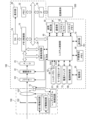
図1は、本発明の実施形態にかかる電子機器の一例としてのデジタルカメラシステムの構成例を示すブロック図である。デジタルカメラシステムは、レンズ交換式デジタルカメラの本体100と、本体100に着脱可能なレンズユニット150とを有している。なお、レンズ交換式であることは本発明に必須でない。
[composition]
1 is a block diagram showing an example of the configuration of a digital camera system as an example of an electronic device according to an embodiment of the present invention. The digital camera system has a
レンズユニット150は、本体100に装着されると本体100に設けられた通信端子10と接触する通信端子6を有する。通信端子10および通信端子6を通じて本体100からレンズユニット150に電源が供給される。また、レンズユニット150のレンズシステム制御回路4と本体100のシステム制御部50とは通信端子10および通信端子6を通じて双方向に通信可能である。
The
レンズユニット150において、レンズ群103は可動レンズを含む複数のレンズから構成される撮像光学系である。可動レンズには少なくともフォーカスレンズが含まれる。また、レンズユニット150によっては、変倍レンズや、ぶれ補正レンズなどの1つ以上がさらに含まれ得る。AF駆動回路3は、フォーカスレンズを駆動するモータやアクチュエータなどを含む。フォーカスレンズは、レンズシステム制御回路4がAF駆動回路3を制御することによって駆動される。絞り駆動回路2は、絞り102を駆動するモータアクチュエータなどを含む。絞り102の開口量は、レンズシステム制御回路4が絞り駆動回路2を制御することによって調整される。
In the
メカニカルシャッタ101はシステム制御部50によって駆動され、撮像素子22の露光時間を調整する。なお、メカニカルシャッタ101は動画撮影時には全開状態に保持される。
The
撮像素子22は例えばCCDイメージセンサやCMOSイメージセンサである。撮像素子22には複数の画素が2次元配置されており、各画素には1つのマイクロレンズ、1つのカラーフィルタ、および1つ以上の光電変換部が設けられている。本実施形態においては、各画素に複数の光電変換部が設けられており、各画素は光電変換部ごとに信号を読み出し可能に構成されている。画素をこのような構成にすることにより、撮像素子22から読み出した信号から撮像画像、視差画像対、および位相差AF用の像信号を生成することができる。
The
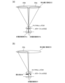
図2(a)は、撮像素子22が有する画素が2つの光電変換部を有する場合の、レンズユニット150の射出瞳と各光電変換部との対応関係を模式的に示した図である。
Figure 2(a) is a diagram showing a schematic diagram of the correspondence between the exit pupil of the
画素に設けられた2つの光電変換部201a,201bは1つのカラーフィルタ252および1つのマイクロレンズ251を共有する。そして、光電変換部201aには射出瞳(領域253)の部分領域253aを通過した光が、光電変換部201bには射出瞳の部分領域253bを通過した光が、それぞれ入射する。
The two photoelectric conversion units 201a and 201b provided in a pixel share one color filter 252 and one microlens 251. Light that has passed through a partial region 253a of the exit pupil (region 253) enters the photoelectric conversion unit 201a, and light that has passed through a
したがって、或る画素領域に含まれる画素について、光電変換部201aから読み出される信号で形成される画像と、光電変換部201bから読み出される信号で形成される画像とは視差画像対を構成する。また、視差画像対は位相差AF用の像信号(A像信号およびB像信号)として用いることができる。さらに、光電変換部201aから読み出される信号と光電変換部201bから読み出される信号とを画素ごとに加算することで、通常の画像信号(撮像画像)を得ることができる。 Therefore, for a pixel included in a certain pixel region, an image formed by the signal read out from photoelectric conversion unit 201a and an image formed by the signal read out from photoelectric conversion unit 201b form a parallax image pair. In addition, the parallax image pair can be used as image signals (A image signal and B image signal) for phase difference AF. Furthermore, a normal image signal (captured image) can be obtained by adding the signal read out from photoelectric conversion unit 201a and the signal read out from photoelectric conversion unit 201b for each pixel.
なお、本実施形態では撮像素子22の各画素が、位相差AF用の信号を生成するための画素(焦点検出用画素)としても、通常の画像信号を生成するための画素(撮像用画像)としても機能する。しかしながら、撮像素子22の一部の画素を焦点検出用画素とし、他の画素を撮像用画素とした構成であってもよい。図2(b)は、焦点検出用画素と、入射光が通過する射出瞳の領域253との対応関係の一例を示している。図2(b)に示す焦点検出用画素において、光電変換部201は、開口部254により、図2(a)の光電変換部201bと同様に機能する。図2(b)に示す焦点検出用画素と、図2(a)の光電変換部201aと同様に機能する別の種類の焦点検出用画素とを、撮像素子22の全体に分散配置することにより、実質的に任意の場所及び大きさの焦点検出領域を設定することが可能になる。
In this embodiment, each pixel of the
図2(a),2(b)に示す構成は、記録用の画像を得るための撮像素子を位相差AF用のセンサとして用いる構成であるが、任意の大きさ及び位置の焦点検出領域を設定可能な他のAFなど、AFの方式に依らず本発明は実施可能である。例えばコントラストAFを用いる構成であっても本発明は実施可能である。コントラストAFのみを用いる場合には、各画素が有する光電変換部は1つである。 The configuration shown in Figures 2(a) and 2(b) uses an image sensor for obtaining an image for recording as a sensor for phase difference AF, but the present invention can be implemented regardless of the AF method, such as other AF that can set a focus detection area of any size and position. For example, the present invention can be implemented even with a configuration that uses contrast AF. When only contrast AF is used, each pixel has one photoelectric conversion unit.
図1に戻り、A/D変換器23は、撮像素子22から出力されるアナログ画像信号をデジタル画像信号(画像データ)に変換するために用いられる。なお、A/D変換器23は撮像素子22が備えてもよい。
Returning to FIG. 1, the A/
A/D変換器23が出力する画像データ(RAW画像データ)は、必要に応じて画像処理部24で処理されたのち、メモリ制御部15を通じてメモリ32に格納される。メモリ32は画像データや音声データを一時的に記憶するバッファメモリとして用いられたり、表示部28用のビデオメモリとして用いられたりする。
The image data (RAW image data) output by the A/
画像処理部24は、画像データに対して予め定められた画像処理を適用し、信号や画像データを生成したり、各種の情報を取得および/または生成したりする。画像処理部24は例えば特定の機能を実現するように設計されたASICのような専用のハードウェア回路であってもよいし、DSPのようなプロセッサがソフトウェアを実行することで特定の機能を実現する構成であってもよい。
The
ここで、画像処理部24が適用する画像処理には、前処理、色補間処理、補正処理、検出処理、データ加工処理、評価値算出処理などが含まれる。前処理には、信号増幅、基準レベル調整、欠陥画素補正などが含まれる。色補間処理は、画像データに含まれていない色成分の値を補間する処理であり、デモザイク処理とも呼ばれる。補正処理には、ホワイトバランス調整、画像の輝度を補正する処理、レンズユニット150の光学収差を補正する処理、色を補正する処理などが含まれる。検出処理には、特徴領域(たとえば顔領域や人体領域)の検出および追尾処理、人物の認識処理などが含まれる。データ加工処理には、スケーリング処理、符号化および復号処理、ヘッダ情報生成処理などが含まれる。評価値算出処理には、位相差AF用の1対の像信号やコントラストAF用の評価値や、自動露出制御に用いる評価値などの算出処理が含まれる。なお、これらは画像処理部24が実施可能な画像処理の例示であり、画像処理部24が実施する画像処理を限定するものではない。また、評価値算出処理はシステム制御部50が行ってもよい。
Here, the image processing applied by the
D/A変換器19は、メモリ32に格納されている表示用の画像データから、表示部28での表示に適したアナログ信号を生成して、生成したアナログ信号を表示部28に供給する。表示部28は例えば液晶表示装置を有し、D/A変換器19からのアナログ信号に基づく表示を表示面上で行う。
The D/
動画の撮像(撮像制御)と、撮像された動画の表示(表示制御)とを継続的に行うことで、表示部28を電子ビューファインダ(EVF)として機能させることができる。表示部28をEVFとして機能させるために表示する動画をライブビュー画像と呼ぶ。表示部28は接眼部を通じて観察するように本体100の内部に設けられてもよいし、接眼部を用いずに観察可能なように本体100の筐体表面に設けられてもよい。表示部28は、本体100の内部と筐体表面との両方に設けられてもよい。
By continuously capturing video (capture control) and displaying the captured video (display control), the
システム制御部50は例えばCPU(MPU、マイクロプロセッサとも呼ばれる)である。システム制御部50は、不揮発性メモリ56に記憶されたプログラムをシステムメモリ52に読み込んで実行することにより、本体100およびレンズユニット150の動作を制御し、カメラシステムの機能を実現する。システム制御部50は、通信端子10および6を通じた通信によってレンズシステム制御回路4に様々なコマンドを送信することにより、レンズユニット150の動作を制御する。
The
不揮発性メモリ56は、システム制御部50が実行するプログラム、カメラシステムの各種の設定値、GUI(Graphical User Interface)の画像データなどを記憶する。システムメモリ52は、システム制御部50がプログラムを実行する際に用いるメインメモリである。不揮発性メモリ56に格納されたデータ(情報)は書き替え可能であってよい。
The
システム制御部50はその動作の一部として、画像処理部24または自身が生成した評価値に基づく自動露出制御(AE)処理を行い、撮影条件を決定する。例えば、静止画撮影の撮影条件はシャッター速度、絞り値、感度である。システム制御部50は、設定されているAEのモードに応じて、シャッター速度、絞り値、感度の1つ以上を決定する。システム制御部50はレンズユニット150の絞り機構の絞り値(開口量)を制御する。また、システム制御部50は、メカニカルシャッタ101の動作も制御する。
As part of its operation, the
また、システム制御部50は、画像処理部24または自身が生成した評価値もしくはデフォーカス量に基づいてレンズユニット150のフォーカスレンズを駆動し、レンズ群103を焦点検出領域内の被写体に合焦させる自動焦点検出(AF)処理を行う。
The
システムタイマー53は内蔵時計であり、システム制御部50が利用する。
The system timer 53 is a built-in clock used by the
操作部70はユーザが操作可能な複数の入力デバイス(ボタン、スイッチ、ダイヤルなど)を有する。操作部70が有する入力デバイスの一部は、割り当てられた機能に応じた名称を有する。シャッターボタン61、モード切り替えスイッチ60、電源スイッチ72は便宜上、操作部70と別に図示ししているが、操作部70に含まれる。表示部28がタッチパネルを備えるタッチディスプレイである場合には、タッチパネルもまた操作部70に含まれる。操作部70に含まれる入力デバイスの操作はシステム制御部50が監視している。システム制御部50は、入力デバイスの操作を検出すると、検出した操作に応じた処理を実行する。
The
シャッターボタン61は半押し状態でONとなり信号SW1を出力する第1シャッタースイッチ62と、全押し状態でONとなり信号SW2を出力する第2シャッタースイッチ64とを有する。システム制御部50は、信号SW1(第1シャッタースイッチ62のON)を検出すると、静止画撮影の準備動作を実行する。準備動作には、AE処理やAF処理などが含まれる。また、システム制御部50は、信号SW2(第2シャッタースイッチ64のON)を検出すると、AE処理で決定した撮影条件に従った静止画の撮影動作(撮像および記録の動作)を実行する。
The
また、本実施形態の操作部70は、ユーザの視線(視線方向)を検出して検出結果(ユーザの視線に関する視線情報)を出力する視線検出部701を有する。システム制御部50は、視線検出部701からの視線情報に応じて各種制御を実行することができる。視線検出部701はユーザが直接操作する部材ではないが、視線検出部701が検出する視線を入力として取り扱うため、操作部70に含めている。
The
図3(a)は、ファインダ内に設ける視線検出部701の構成例を模式的に示す側面図である。視線検出部701は、本体100の内部に設けられた表示部28をファインダのアイピースを通じて見ているユーザの眼球501aの光軸の回転角を視線の方向として検出する。検出された視線の方向に基づいて、ユーザが表示部28で注視している位置(表示画像中の注視点)を特定することができる。
Figure 3(a) is a side view showing a schematic configuration example of a
表示部28には例えばライブビュー画像が表示され、ユーザはアイピースの窓を覗き込むことにより、表示部28の表示内容を接眼レンズ701dおよびダイクロックミラー701cを通じて観察することができる。光源701eは、アイピースの窓方向(本体100の外部方向)に赤外光を発することができる。ユーザがファインダを覗いている場合には、光源701eが発した赤外光は眼球501aで反射されてファインダ内に戻ってくる。ファインダに入射した赤外光はダイクロックミラー701cで受光レンズ701b方向に反射される。
For example, a live view image is displayed on the
受光レンズ701bは、赤外光による眼球像を撮像素子701aの撮像面に形成する。撮像素子701aは赤外光撮像用のフィルタを有する2次元撮像素子である。視線検出用の撮像素子701aの画素数は撮影用の撮像素子22の画素数よりも少なくてよい。撮像素子701aによって撮像された眼球画像はシステム制御部50に送信される。システム制御部50は、眼球画像から赤外光の角膜反射の位置と瞳孔の位置とを検出し、両者の位置関係から視線方向を検出する。また、システム制御部50は、検出した視線方向に基づ
いて、ユーザが注視している表示部28の位置(表示画像中の注視点)を検出する。なお、眼球画像から角膜反射の位置と瞳孔の位置を画像処理部24で検出し、システム制御部50は画像処理部24からこれらの位置を取得してもよい。
The
なお、本発明は視線検出の方法や視線検出部の構成には依存しない。したがって、視線検出部701の構成は図3(a)に示したものに限定されない。例えば、図3(b)に示すように、本体100の背面に設けられた表示部28の近傍に配置されたカメラ701fにより撮像された画像に基づいて視線を検出してもよい。破線で示すカメラ701fの画角は、表示部28を見ながら撮影を行うユーザの顔が撮像されるように定められている。カメラ701fで撮像した画像から検出した目領域(眼球501aと眼球501の少なくとも一方の領域)の画像に基づいて視線の方向を検出することができる。赤外光の画像を用いる場合には、カメラ701fの近傍に光源701eを配置し、光源701eで画角内の被写体に赤外光を投写して撮像を行えばよい。その場合は、得られた画像から視線の方向を検出する方法は図3(a)の方法と同様でよい。また、可視光の画像を用いる場合には光を投射しなくてもよい。可視光の画像を用いる場合には、目領域の目頭と虹彩の位置関係などから視線の方向を検出することができる。
Note that the present invention does not depend on the method of gaze detection or the configuration of the gaze detection unit. Therefore, the configuration of the
再び図1に戻り、電源制御部80は、電池検出回路、DC-DCコンバータ、通電するブロックを切り替えるスイッチ回路等により構成され、電池の装着の有無、電池の種類、電池残量の検出を行う。また、電源制御部80は、検出結果及びシステム制御部50の指示に基づいてDC-DCコンバータを制御し、必要な電圧を必要な期間、記録媒体200を含む各部へ供給する。
Returning to FIG. 1, the power supply control unit 80 is composed of a battery detection circuit, a DC-DC converter, a switch circuit that switches between blocks to which electricity is applied, and the like, and detects whether a battery is installed, the type of battery, and the remaining battery power. The power supply control unit 80 also controls the DC-DC converter based on the detection results and instructions from the
電源部30は、電池やACアダプター等からなる。I/F18は、メモリカードやハードディスク等の記録媒体200とのインターフェースである。記録媒体200には、撮影された画像や音声などのデータファイルが記録される。記録媒体200に記録されたデータファイルはI/F18を通じて読み出され、画像処理部24およびシステム制御部50を通じて再生することができる。
The
通信部54は、無線通信および有線通信の少なくとも一方による外部機器との通信を実現する。撮像素子22で撮像した画像(撮像画像;ライブビュー画像を含む)や、記録媒体200に記録された画像は、通信部54を通じて外部機器に送信可能である。また、通信部54を通じて外部機器から画像データやその他の各種情報を受信することができる。
The communication unit 54 realizes communication with an external device by at least one of wireless communication and wired communication. Images captured by the image sensor 22 (captured images; including live view images) and images recorded on the
姿勢検出部55は重力方向に対する本体100の姿勢を検出する。姿勢検出部55は加速度センサ、または角速度センサであってよい。システム制御部50は、撮影時に姿勢検出部55で検出された姿勢に応じた向き情報を、当該撮影で得られた画像データを格納するデータファイルに記録することができる。向き情報は、例えば記録済みの画像を撮影時と同じ向きで表示するために用いることができる。
The
本実施形態の本体100は、画像処理部24が検出した特徴領域が適切な画像となるように各種の制御を実施することが可能である。例えば、本体100は、特徴領域で合焦させる自動焦点検出(AF)や、特徴領域が適正露出となるような自動露出制御(AE)を実施することが可能である。また、本体100は、特徴領域のホワイトバランスが適切になるような自動ホワイトバランスや、特徴領域の明るさが適切になるような自動フラッシュ光量調整なども実施することが可能である。なお、特徴領域を適切にする制御は、これらに限定されない。画像処理部24は、例えばライブビュー画像に対して公知の方法を適用して、予め定められた特徴に当てはまると判定される領域を特徴領域として検出し、各特徴領域の位置、大きさ、信頼度といった情報をシステム制御部50に出力する。なお、本発明は特徴領域の種類や検出方法には依存しない。また特徴領域の検出には公知の方法
を利用可能であるため、特徴領域の検出方法についての説明は省略する。
The
また、特徴領域は、被写体情報を検出するためにも用いることができる。特徴領域が顔領域の場合、被写体情報として、例えば、赤目現象が生じているか否か、目をつむっているか否か、表情(例えば笑顔)などが検出される。なお、被写体情報はこれらに限定されない。 The feature region can also be used to detect subject information. When the feature region is a face region, the subject information detected may include, for example, whether or not red-eye is occurring, whether or not the eyes are closed, and facial expression (e.g., smiling). Note that the subject information is not limited to these.
本実施形態では、大きさおよび位置が不定である複数の画像領域の一例としての複数の特徴領域から、各種の制御に用いたり、被写体情報を取得したりするための1つの特徴領域(主被写体領域)を、ユーザの視線を用いて選択することができる。視線検出部701で検出されるようにユーザが視線を向ける動作は、視線入力と呼ぶことができる。
In this embodiment, from among multiple feature regions, which are examples of multiple image regions whose sizes and positions are indefinite, one feature region (main subject region) to be used for various controls or to obtain subject information can be selected using the user's gaze. The action of the user directing their gaze as detected by the
[動作]
以下、図4を参照して、本体100で行われる撮影処理について説明する。図4は、本実施形態に係る撮影処理のフローチャートである。撮影モードで本体100が起動したことや、本体100のモードとして撮影モードが設定されたことなどに応じて、図4の処理が開始される。
[Action]
The photographing process performed by the
ステップS1では、システム制御部50は、撮像素子22の駆動を開始し、撮像データ(画像)の取得を開始する。これにより、焦点検出や被写体検出、ライブビュー表示などの少なくともいずれかを行うために十分な解像度を有する画像が順次取得される。ここでは、ライブビュー表示用の動画撮像のための駆動動作であるため、ライブビュー表示用のフレームレートに応じた時間の電荷蓄積を撮像データの読み出しの度に行う、いわゆる電子シャッタを用いた撮像を行う。ライブビュー表示は、表示部28を電子ビューファインダ(EVF)として機能させる表示であり、被写体を略リアルタイムで表す表示である。ライブビュー表示は、例えば、ユーザ(撮影者)が撮影範囲や撮影条件の確認を行うために行われ、ライブビュー表示用のフレームレートは、例えば、30フレーム/秒(撮像間隔33.3ms)や60フレーム/秒(撮像間隔16.6ms)などである。
In step S1, the
ステップS2では、システム制御部50は、現在の撮像データから焦点検出データと撮像画像データを取得する処理を開始する。焦点検出データは、焦点検出領域における視差画像対を構成する第1画像と第2画像のデータを含む。例えば、第1画像を構成する画素のデータは、図2(a)の光電変換部201aから得られるデータであり、第2画像を構成する画素のデータは、光電変換部201bから得られるデータである。撮像画像データは、撮像画像のデータであり、第1画像のデータと第2画像のデータとを足し合わせ、画像処理部24で色補間処理などを適用して得られるデータである。このように、1回の撮像により、焦点検出データと撮像画像データを取得することができる。なお、焦点検出用画素と撮像用画素とを別々の画素とした場合には、焦点検出用画素の位置での画素値を得る補間処理などを行って撮像画像データを取得する。
In step S2, the
ステップS3では、システム制御部50はライブビュー表示処理を開始する。システム制御部50は、ライブビュー表示処理において、画像処理部24を用いて現在の撮像画像(撮像画像データ)からライブビュー表示用の画像を生成し、生成した画像を表示部28の画像表示領域に表示する。画像表示領域は、表示部28の表示面の全領域、表示部28に表示された画面(ウィンドウなど)の全領域、表示面または画面の一部の領域などのいずれかである。なお、ライブビュー表示用の画像は、例えば、表示部28の解像度に合わせた縮小画像であり、撮像画像を生成する際に画像処理部24で縮小処理を実施することもできる。この場合には、システム制御部50は、生成された撮像画像(縮小処理後の画像)を表示部28に表示する。上述したように、ライブビュー表示は被写体を略リアルタイムで表すため、ユーザは、ライブビュー表示を確認しながら、撮影時の構図や露出条件
の調整などを容易に行うことができる。さらに、本実施形態では、本体100は、撮像画像から、人物の顔や動物などの被写体を検出することができる。このため、ライブビュー表示において、検出している被写体の領域を示す枠などの表示も行うことができる。
In step S3, the
ステップS4では、システム制御部50は、視線検出と焦点検出を開始する。視線検出では、視線検出部701により、表示部28の表示面における視線位置(ユーザの視線の位置)を示す視線情報が、ユーザが見ていた撮像画像と関連付けて、所定の時間間隔で取得される。さらに、ステップS4では、システム制御部50は、検出された視線位置をユーザに通知するため、表示部28の表示面における視線位置への所定のアイテム(丸など)の表示を開始する。焦点検出については後述する。
In step S4, the
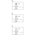
本実施形態では、所定の条件Aが満たされた否かに応じて、視線位置の表示状態を、視線位置(所定のアイテム)を常に表示する第1状態と、線種の変更、点滅、変色などにより視線位置の表示を第1状態よりも抑制した第2状態との間で切り替える。図6(a)は第1状態の表示例を示し、図6(b),6(c)は第2状態の表示例を示す。第1状態の図6(a)では、視線位置が太線601で表示されており、第2状態の図6(b)では、視線位置が細線602で表示されており、第2状態の図6(c)では、視線位置が破線603で表示されている。第2状態は、第1状態よりも視線位置の視認性が低い表示状態とも言える。図5(a)は、そのような切り替え処理(表示状態の切り替え処理)のフローチャートである。
In this embodiment, depending on whether a predetermined condition A is satisfied, the display state of the gaze position is switched between a first state in which the gaze position (predetermined item) is always displayed, and a second state in which the display of the gaze position is suppressed more than in the first state by changing the line type, blinking, discoloration, etc. FIG. 6(a) shows a display example of the first state, and FIGS. 6(b) and 6(c) show display examples of the second state. In FIG. 6(a) of the first state, the gaze position is displayed by a
ステップS20では、システム制御部50は、条件Aが満たされたか否かを判定する。システム制御部50は、条件Aが満たされたと判定した場合にステップS22へ処理を進め、条件Aが満たされなかったと判定した場合にステップS21へ処理を進める。ステップS21では、システム制御部50は、視線位置の表示状態を、視線位置を常に表示する第1状態に制御する。ステップS22では、システム制御部50は、視線位置の表示状態を、非表示や点滅、変色などにより視線位置の表示を第1状態よりも抑制した第2状態に制御する。
In step S20, the
視線情報の信頼度(視線情報によって示された位置とユーザが意図した位置との一致度)は一定ではなく、変化し得る。そして、視線情報の信頼度が所定の閾値未満の場合には、視線情報に基づく処理がユーザの意図通りに行われない可能性が高い。そのため、視線情報の信頼度が所定の閾値未満であるという条件を、条件Aに含めることが好ましい。ここで、視線情報の信頼度が所定の閾値未満であるという条件を条件Aとして用いる場合を考える。システム制御部50は、視線情報を取得する度に、取得した視線情報の信頼度を算出し、図5(a)の切り替え処理を行う。ステップS20では、システム制御部50は、視線情報の信頼度が所定の閾値未満であるか否かを判定する。信頼度が所定の閾値以上の場合には、ステップS21へ処理が進められ、システム制御部50は、視線位置の表示状態を第1状態に制御する。一方で、信頼度が所定の閾値未満の場合には、ステップS22へ処理が進められ、システム制御部50は、視線位置の表示状態を第2状態に制御する。こうすることで、視線位置の表示状態を好適に制御することができる。具体的には、信頼度の高い視線情報が本体100で取得できている否か、視線情報に基づく処理がユーザの意図通りに行われない可能性の有無などをユーザに容易に把握させることができる。なお、視線情報の信頼度を算出する方法は特に限定されない。システム制御部50は、視線情報の信頼度を算出せずに、視線情報の信頼度が所定の閾値未満の状態に対応する状態を検出してもよい(詳細は後述する)。
The reliability of the gaze information (the degree of agreement between the position indicated by the gaze information and the position intended by the user) is not constant and may change. If the reliability of the gaze information is less than a predetermined threshold, it is highly likely that the processing based on the gaze information will not be performed as intended by the user. Therefore, it is preferable to include in condition A the condition that the reliability of the gaze information is less than a predetermined threshold. Here, consider a case where the condition that the reliability of the gaze information is less than a predetermined threshold is used as condition A. Each time gaze information is acquired, the
図4に戻り、ステップS5では、システム制御部50は、信号SW1(第1シャッタースイッチ62のON;撮影準備指示;シャッターボタン61の半押し状態)が検出された否かを判定する。システム制御部50は、信号SW1が検出されたと判定した場合にステ
ップS6へ処理を進め、信号SW1が検出されなかったと判定した場合にステップS13へ処理を進める。
4, in step S5, the
ステップS6では、システム制御部50は、焦点検出領域の設定と、ステップS4で開始した焦点検出とを行う。ここでは、システム制御部50は、現在の視線位置と、現在の撮像画像から検出された被写体の位置とに基づいて、焦点検出領域を設定する。例えば、検出された複数の被写体のうち、視線位置に最も近い被写体の領域(視線位置を含む領域)を、焦点検出領域に設定することができる。そして、システム制御部50は、焦点検出領域で合焦する焦点位置(合焦点)を検出する。ステップS6以降では、視線情報を用いた焦点検出(焦点検出領域の設定を含む)が繰り返し実行される。なお、視線情報が取得される前の焦点検出領域の設定方法は特に限定されない。例えば、ユーザが任意に選択した被写体の領域を、焦点検出領域として設定することができる。
In step S6, the
システム制御部50は、焦点検出を行う際に、焦点検出の精度を高める(保障する)ために露出制御も行う。システム制御部50は、この露出制御により取得した露出情報(撮像画像の露出情報)から、視線位置における露出状態を判別することができる。視線位置における露出状態が飽和状態(高輝度状態)や低輝度状態である場合には、ユーザが視線位置の被写体を正しく視認できていない可能性が高く、視認情報の信頼度が低い可能性が高い。そのため、視線位置での露出が所定の範囲外の不適正露出であるという条件と条件Aに含めて、図5(a)の切り替え処理を行うことが好ましい。そのような切り替え処理は、露出制御により露出情報を取得した後に行われる。なお、露出が所定の範囲の最大値を超えている状態が飽和状態であり、露出が所定の範囲の最小値を下回った状態が低輝度状態である。また、視線位置での露出が所定の範囲外の不適正露出である状態(飽和状態や低輝度状態)は、視線情報の信頼度が所定の閾値未満の状態に対応する状態とも言える。
When performing focus detection, the
ここで、図5(a)の切り替え処理において、視線位置での露出が所定の範囲外の不適正露出であるという条件を条件Aとして用いる場合を考える。ステップS20では、システム制御部50は、取得した露出情報に基づいて、視線位置での露出が所定の範囲外の不適正露出であるか否かを判定する。露出が不適正露出でない場合(露出が適正露出である場合)には、ステップS21へ処理が進められ、システム制御部50は、視線位置の表示状態を第1状態に制御する。一方で、露出が不適正露出である場合には、ステップS22へ処理が進められ、システム制御部50は、視線位置の表示状態を第2状態に制御する。
Now, consider a case where, in the switching process of FIG. 5(a), the condition that the exposure at the gaze position is improperly exposed outside a predetermined range is used as condition A. In step S20, the
なお、焦点検出時における露出制御で取得する露出情報から、視線位置における露出状態を判別する例を説明したが、視線位置における露出状態の判別の方法やタイミングは特に限定されず、他の方法やタイミングで露出状態が判別されてもよい。 Note that, although an example has been described in which the exposure state at the gaze position is determined from the exposure information acquired by exposure control during focus detection, the method and timing of determining the exposure state at the gaze position are not particularly limited, and the exposure state may be determined by other methods and timings.
焦点検出では、焦点検出領域における視差画像対を構成する第1画像と第2画像の像ずれ量(位相差)が算出され、像ずれ量から焦点検出領域におけるデフォーカス量(大きさと方向を含むベクトル量)が算出される。以下、焦点検出について具体的に説明する。 In focus detection, the amount of image shift (phase difference) between the first image and the second image that make up the parallax image pair in the focus detection area is calculated, and the amount of defocus (vector quantity including magnitude and direction) in the focus detection area is calculated from the amount of image shift. Focus detection is explained in detail below.
まず、システム制御部50は、第1画像と第2画像にシェーディング補正を施すことにより、第1画像と第2画像の間の光量差(輝度差)を低減する。さらに、システム制御部50は、シェーディング補正後の第1画像と第2画像にフィルター処理を施すことにより、位相差検出を行う空間周波数の画像(データ)を抽出する。
First, the
次に、システム制御部50は、フィルター処理後の第1画像と第2画像を相対的に瞳分割方向にシフトさせるシフト処理を行い、第1画像と第2画像の一致度を表す相関値を算出する。
Next, the
ここで、フィルター処理後の第1画像におけるk番目の画素のデータをA(k)とし、フィルター処理後の第2画像におけるk番目の画素のデータをB(k)とし、焦点検出領域に対応する番号kの範囲をWとする。さらに、シフト処理によるシフト量をs1として、シフト量s1の範囲(シフト範囲)をΓ1とする。この場合に、相関値COR(s1)は、以下の式1を用いて算出できる。
![]()
![]()
具体的には、シフト量s1のシフト処理により、フィルター処理後の第1画像におけるk番目の画素のデータA(k)に、フィルター処理後の第2画像におけるk-s1番目の画素のデータB(k-s1)を対応付ける。次に、データA(k)からデータB(k-s1)を減算し、減算結果の絶対値を算出する。そして、焦点検出領域に対応する範囲W内で算出された絶対値の総和を、相関値COR(s1)として算出する。なお、必要に応じて、行毎に算出された相関量を、シフト量毎に、複数行に亘って加算してもよい。 Specifically, by shifting by a shift amount s1, data A(k) of the kth pixel in the first image after filtering is associated with data B(k-s1) of the k-s1th pixel in the second image after filtering. Next, data B(k-s1) is subtracted from data A(k) to calculate the absolute value of the subtraction result. Then, the sum of the absolute values calculated within the range W corresponding to the focus detection area is calculated as the correlation value COR(s1). Note that, if necessary, the correlation amount calculated for each row may be added across multiple rows for each shift amount.
次に、システム制御部50は、相関値から、サブピクセル演算により、相関値が最小となる実数値のシフト量を、像ずれ量p1として算出する。そして、システム制御部50は、算出した像ずれ量p1に、焦点検出領域の像高と、撮像レンズ(結像光学系;撮像光学系)のF値と、射出瞳距離とに応じた変換係数K1を乗算することにより、デフォーカス量を算出する。
Next, the
ステップS7では、システム制御部50は、ステップS6で検出(算出)したデフォーカス量に基づき、フォーカスレンズを駆動する。検出されたデフォーカス量が所定値より小さい場合には、必ずしもフォーカスレンズを駆動する必要はない。
In step S7, the
フォーカスレンズを駆動する(移動させる)と像面移動が発生するため、撮像画像が変化する。デフォーカス量が大きい場合には、撮像画像の変化量も大きくなる。ユーザは、このような撮像画像の変化を予期することが難しく、フォーカスレンズの大きな駆動や速い駆動が行われる場合には、ユーザが視線で追っていた被写体をうまく視線で追えなくなる可能性が高く、視認情報の信頼度が低減する可能性が高い。そのため、フォーカスレンズの駆動量が所定の閾値よりも大きいという条件や、フォーカスレンズの駆動速度が所定の閾値よりも大きいという条件を条件Aに含めて、図5(a)の切り替え処理を行うことが好ましい。そのような切り替え処理は、フォーカスレンズを駆動する前(際)に行われる。なお、システム制御部50は、検出したデフォーカス量から、フォーカスレンズの駆動量やフォーカスレンズの駆動速度を判別することができる。また、フォーカスレンズの駆動量が所定の閾値よりも大きい状態や、フォーカスレンズの駆動速度が所定の閾値よりも大きい(速い)状態は、視線情報の信頼度が所定の閾値未満の状態に対応する状態とも言える。
When the focus lens is driven (moved), the image plane moves, so the captured image changes. When the defocus amount is large, the change in the captured image also increases. It is difficult for the user to predict such changes in the captured image, and when the focus lens is driven large or fast, it is highly likely that the user will not be able to follow the subject that he or she was following with their line of sight, and the reliability of the visual information is highly likely to decrease. Therefore, it is preferable to perform the switching process of FIG. 5(a) by including in condition A the condition that the drive amount of the focus lens is larger than a predetermined threshold value and the condition that the drive speed of the focus lens is larger than a predetermined threshold value. Such a switching process is performed before (when) the focus lens is driven. The
ここで、図5(a)の切り替え処理において、フォーカスレンズの駆動量が所定の閾値よりも大きいという条件を条件Aとして用いる場合を考える。ステップS20では、システム制御部50は、フォーカスレンズの駆動量が所定の閾値よりも大きいか否かを判定する。駆動量が所定の閾値以下である場合には、ステップS21へ処理が進められ、システム制御部50は、視線位置の表示状態を第1状態に制御する。一方で、駆動量が所定の閾値よりも大きい場合には、ステップS22へ処理が進められ、システム制御部50は、視線位置の表示状態を第2状態に制御する。
Now, consider a case where the condition A is that the drive amount of the focus lens is greater than a predetermined threshold in the switching process of FIG. 5(a). In step S20, the
撮像光学系のズームレンズを駆動する(移動させる)場合も、像倍率変化が発生し、フォーカスレンズを駆動する場合と同様に、撮像画像の変化が発生する。そのため、ズームレンズの駆動量が所定の閾値よりも大きいという条件や、ズームレンズの駆動速度が所定の閾値よりも大きいという条件を条件Aに含めて、図5(a)の切り替え処理を行うことが好ましい。そのような切り替え処理は、ズームレンズの駆動を検出できる場合に実行でき、ズームレンズを駆動する前(際)に実行される。なお、ズームレンズは、例えば、ユーザがレンズユニット150や操作部70を操作することによって任意のタイミングで動かされる。そして、システム制御部50は、レンズユニット150や操作部70に対する操作などの、ズームレンズを駆動する指示から、ズームレンズの駆動量やズームレンズの駆動速度を判別することができる。また、ズームレンズの駆動量が所定の閾値よりも大きい状態や、ズームレンズの駆動速度が所定の閾値よりも大きい(速い)状態は、視線情報の信頼度が所定の閾値未満の状態に対応する状態とも言える。
When driving (moving) the zoom lens of the imaging optical system, the image magnification also changes, and the captured image changes in the same way as when driving the focus lens. Therefore, it is preferable to perform the switching process of FIG. 5(a) by including in condition A the condition that the driving amount of the zoom lens is greater than a predetermined threshold value and the condition that the driving speed of the zoom lens is greater than a predetermined threshold value. Such switching process can be performed when the driving of the zoom lens can be detected, and is performed before (when) the zoom lens is driven. Note that the zoom lens is moved at any timing, for example, by the user operating the
また、フォーカスレンズやズームレンズといった撮像光学系の駆動以外に、撮像画像の変化(変動)を発生させる要因として、本体100の振れ(揺れ;本体100を持つ手の振れに起因した手振れなど)がある。本体100が大きく揺れている場合には、撮影範囲(撮像範囲)や、表示部28の表示面(表示面上での撮像画像)も大きく揺れているため、ユーザが所望の被写体をうまく視線で追えない可能性が高く、視認情報の信頼度が低い可能性が高い。そのため、本体100の振れ量が所定の閾値よりも大きいという条件と条件Aに含めて、図5(a)の切り替え処理を行うことが好ましい。そのような切り替え処理は、本体100の振れを検出できる場合に実行でき、本体100の振れを検知した後に行われる。なお、システム制御部50は、姿勢検出部55による検出の結果から、本体100の振れの種別や量を判別することができる。また、本体100の振れ量(揺れ量)が所定の閾値よりも大きい状態は、視線情報の信頼度が所定の閾値未満の状態に対応する状態とも言える。
In addition to the driving of the imaging optical system such as the focus lens and the zoom lens, a factor that causes a change (fluctuation) in the captured image is the shaking of the main body 100 (shaking; hand shaking caused by shaking of the hand holding the
ステップS8では、システム制御部50は、ステップS1~S4で開始した処理(撮像、ライブビュー表示、視線検出、視線位置の表示、焦点検出など)を行う。焦点検出の方法は、ステップS6の方法(視線情報を用いた焦点検出)と同様である。なお、ステップS8の処理は、ステップS7の処理中(フォーカスレンズの駆動中)に、並列的に行ってもよい。また、ライブビュー表示(撮像画像)の変化や、視線位置の変化などに基づいて、焦点検出領域を変更してもよい。
In step S8, the
ステップS9では、システム制御部50は、信号SW2(第2シャッタースイッチ64のON;撮影指示;シャッターボタン61の全押し状態)が検出された否かを判定する。システム制御部50は、信号SW2が検出されたと判定した場合にステップS10へ処理を進め、信号SW2が検出されなかったと判定した場合にステップS5へ処理を戻す。
In step S9, the
ステップS10では、システム制御部50は、撮像画像の記録(撮影)を行うか否かを判定する。システム制御部50は、撮像画像の記録を行うと判定した場合にステップS11へ処理を進め、撮像画像の記録を行わないと判定した場合にステップS12へ処理を進める。本実施形態では、第2シャッタースイッチ64の長押しで連写(連写撮影;連続撮影)が行われ、連写中には、撮影(撮像画像の記録)と焦点検出の間で処理が切り替えられる。撮影と焦点検出が交互に行われるように、1回の撮像の度に処理を切り替えてもよい。複数回(例えば、3回)の撮像の度に1回の焦点検出が行われるように処理を切り替えてもよい。これにより、単位時間当たりの撮影枚数を大幅に減らすことなく、焦点検出を好適に行うことができる。
In step S10, the
ステップS11では、システム制御部50は、撮像画像を記録媒体200に記録する。また、システム制御部50は、必要に応じて、記録(撮影)された画像を表示部28に表
示する(画像確認表示)。撮影指示が画像確認表示の指示を兼ねて、撮影後に画像確認表示が自動で行われてもよい。操作部70が撮影指示とは別の指示(操作)を受け付け、システム制御部50が、当該指示に応じて画像確認表示のための制御を行ってもよい。ステップS11の後、ステップS9へ処理が戻される。
In step S11, the
画像確認表示は、例えば、撮影された画像をユーザに確認させるために行われ、画像確認表示が実行中である場合には、視線位置(視線情報)の取得や表示を必要としない。このため、画像確認表示の指示があったという条件や、画像確認表示の実行中であるという条件を条件Aに含めて、図5(a)の切り替え処理を行うことが好ましい。こうすることで、視線位置の表示状態をより好適に制御することができる。具体的には、視線情報に基づく処理が実行可能な状態か否かなどをユーザに容易に把握させることができる。上述したように、システム制御部50は、操作部70(シャッターボタン61を含む)がユーザから受け付けた指示に応じて、画像確認表示のための制御を行う。このため、システム制御部50は、操作部70(シャッターボタン61を含む)がユーザから受け付けた指示に応じて、画像確認表示の指示があったか否かや、画像確認表示の実行中であるか否かを判別することができる。
The image confirmation display is performed, for example, to allow the user to confirm the captured image, and when the image confirmation display is being executed, it is not necessary to acquire or display the gaze position (gaze information). For this reason, it is preferable to perform the switching process of FIG. 5(a) by including the condition that an instruction for image confirmation display has been given and the condition that the image confirmation display is being executed in condition A. In this way, the display state of the gaze position can be controlled more suitably. Specifically, the user can easily understand whether or not the processing based on the gaze information is in a state where it can be executed. As described above, the
同様に、撮影画面(撮影を行う画面)とは異なる画面が表示部28で表示中である場合にも、視線位置(視線情報)の取得や表示を必要としないことがある。このため、撮影画面とは異なる画面が表示部28で表示中であるという条件や、撮影画面とは異なる画面を表示部28に表示する指示があったという条件を条件Aに含めて、図5(a)の切り替え処理を行うことが好ましい。撮影画面とは異なる画面は、例えば、カメラシステムの設定を変更するためのカメラ設定変更画面(メニュー画面)や、カメラシステムを外部装置と通信させるための通信画面などである。画像確認表示と同様に、システム制御部50は、操作部70がユーザから受け付けた指示に応じて、撮影画面とは異なる画面を表示するための制御を行う。このため、システム制御部50は、操作部70がユーザから受け付けた指示に応じて、撮影画面とは異なる画面の表示中であるか否かや、撮影画面とは異なる画面を表示する指示があったか否かを判別することができる。
Similarly, even when a screen other than the shooting screen (a screen on which shooting is performed) is being displayed on the
一方で、撮影画面(ライブビュー画面)とは異なる画面が撮影画面とともに表示されている場合は、撮影画面を確認しつつ視線によって操作を行えるようにするために、継続して視線検出および検出された視線位置に基づく指示を受け付けてもよい。 On the other hand, if a screen other than the shooting screen (live view screen) is displayed together with the shooting screen, gaze detection may be continued and instructions based on the detected gaze position may be accepted so that operations can be performed by gaze while checking the shooting screen.
また、マニュアルフォーカス(手動での焦点調整)を行う場合にも、視線位置(視線情報)の取得や表示を必要としないことがある。このため、マニュアルフォーカス中であるという条件や、マニュアルフォーカスを開始する指示があったという条件を条件Aに含めて、図5(a)の切り替え処理を行うことが好ましい。なお、マニュアルフォーカスを行う場合には、ステップS7のフォーカスレンズ駆動や、ステップS4,S6~8,S12の焦点検出を図4の撮影処理から除いた処理が行われる。マニュアルフォーカスでは、フォーカスレンズが手動で駆動される。また、マニュアルフォーカスは、操作部70がユーザから受け付けた指示に応じて、システム制御部50により設定される。このため、システム制御部50は、操作部70がユーザから受け付けた指示に応じて、マニュアルフォーカス中であるか否かや、マニュアルフォーカスを開始する指示があったか否かを判別することができる。
In addition, even when performing manual focus (manual focus adjustment), it may not be necessary to obtain or display the gaze position (gaze information). For this reason, it is preferable to perform the switching process of FIG. 5(a) by including the condition that manual focus is being performed or the condition that an instruction to start manual focus has been given in condition A. Note that, when performing manual focus, a process is performed in which the focus lens driving in step S7 and the focus detection in steps S4, S6 to S8, and S12 are removed from the shooting process in FIG. 4. In manual focus, the focus lens is driven manually. Also, manual focus is set by the
さらに、マニュアルフォーカスでは、ユーザはピントを合わせたい位置に焦点位置を手動で調整するため、細かなピントの変化を撮影画像から視認する必要がある。このため、視線位置が視認性良く表示されている場合には、ユーザが焦点位置の調整を好適に行えない可能性が高い(操作性の低下)。このため、マニュアルフォーカス中での視線位置の表示状態(第2状態)は、視認性が十分に低い状態であることが好ましく、非表示の状態で
あることが特に好ましい。こうすることで、焦点位置の調整を好適に行いやすくすることができる(操作性の向上)。
Furthermore, in manual focus, the user manually adjusts the focal position to the desired position, and therefore needs to visually check the minute changes in focus from the captured image. Therefore, if the gaze position is displayed with good visibility, there is a high possibility that the user will not be able to adjust the focal position appropriately (decreased operability). Therefore, it is preferable that the display state (second state) of the gaze position during manual focus is in a state with sufficiently low visibility, and it is particularly preferable that it is in a non-display state. This makes it easier to adjust the focal position appropriately (improved operability).
ステップS12では、システム制御部50は、ステップS8と同様に、ステップS1~S4で開始した処理(撮像、ライブビュー表示、視線検出、視線位置の表示、焦点検出など)を行う。但し、連写のフレームレート(撮像コマ速)や、撮像画像から記録画像(記録する画像)を生成する生成処理などにより、ステップS12では、撮像画像の表示期間や表示更新レート(間隔)、表示遅延などがステップS8と異なる。ステップS12の後、ステップS9へ処理が戻される。
In step S12, the
連写中は、シャッターが切られることによりブラックアウトが発生したり、画像確認表示が行われたりする。このため、ユーザは表示部28(電子ビューファインダ)で被写体を視認することが難しく、視認情報の信頼度が低い可能性が高い。そのため、連写中であるという条件と条件Aに含めて、図5(a)の切り替え処理を行うことが好ましい。システム制御部50は、操作部70(シャッターボタン61を含む)がユーザから受け付けた指示に応じて、連写のための制御を行う。このため、システム制御部50は、操作部70(シャッターボタン61を含む)がユーザから受け付けた指示に応じて、連写中であるか否かを判別することができる。また、連写中である状態は、視線情報の信頼度が所定の閾値未満の状態に対応する状態とも言える。
During continuous shooting, a blackout occurs when the shutter is released, or an image confirmation display is performed. This makes it difficult for the user to visually confirm the subject on the display unit 28 (electronic viewfinder), and the reliability of the visual confirmation information is likely to be low. Therefore, it is preferable to perform the switching process of FIG. 5(a) by including the condition that continuous shooting is in progress in condition A. The
上述したように、ステップS5で信号SW1が検出されなかった場合には、ステップS13へ処理が進められる。ステップS13では、システム制御部50は、撮影処理の終了指示(操作)があったか否かを判定する。終了指示は、例えば、本体100のモードを撮影モードから他のモードへ変更する指示や、本体100の電源を切る指示などである。システム制御部50は、終了指示があったと判定した場合に図4の撮影処理を終了し、終了指示が無かったと判定した場合にステップS5へ処理を戻す。
As described above, if signal SW1 is not detected in step S5, the process proceeds to step S13. In step S13, the
なお、所定の条件Bが満たされた否かに応じて、視線検出(視線情報の取得)の実行/非実行を切り替えてもよい。図5(b)は、そのような切り替え処理(視線検出の実行/非実行の切り替え処理)のフローチャートである。 Note that the execution/non-execution of gaze detection (acquisition of gaze information) may be switched depending on whether a predetermined condition B is satisfied. FIG. 5(b) is a flowchart of such a switching process (switching between execution/non-execution of gaze detection).
ステップS30では、システム制御部50は、条件Bが満たされたか否かを判定する。システム制御部50は、条件Bが満たされたと判定した場合にステップS32へ処理を進め、条件Aが満たされなかったと判定した場合にステップS31へ処理を進める。ステップS31では、システム制御部50は、視線検出を実行する(視線検出を開始する)ように制御する。ステップS32では、システム制御部50は、視線検出を実行しない(視線検出を停止する)ように制御する。ステップS32の処理が行われると、視線情報が取得されなくなるため、視線位置は非表示となる。視線検出を停止することにより、視線検出部701への電源供給を停止することができ、電力消費を低減することができる。さらに、視線検出に関する処理を省略することができ、処理負荷を低減することができる。なお、システム制御部50は、視線検出部701による視線の検出を停止せずに、視線検出部701からの視線情報の取得を停止してもよい。そうすることにより、視線情報が取得される状態への復帰を短時間で行うことが可能となる。
In step S30, the
条件Bは条件Aと同じであってもよいし、異なっていてもよい。視線位置(視線情報)の取得や表示を必要としない場合や、視認情報の信頼度が特に低い場合には、視線位置を表示しないことが好ましい。このため、そられの場合に対応する以下の条件の少なくともいずれかを条件Bに含めることが好ましい。
・画像確認表示の指示があったという条件
・撮影画面とは異なる画面を表示部28で表示中であるという条件
・連写中であるという条件
・マニュアルフォーカス中であるという条件
Condition B may be the same as or different from condition A. When there is no need to acquire or display the gaze position (gaze information) or when the reliability of the visual information is particularly low, it is preferable not to display the gaze position. For this reason, it is preferable to include at least one of the following conditions corresponding to these cases in condition B.
A condition that an instruction for image confirmation display has been given; A condition that an image other than the shooting image is being displayed on the
上述した条件Aの候補を以下にまとめるが、条件Aは以下の条件のうちの1つの条件であってもよいし、複数の条件を含んでもよい。
・画像確認表示の指示があったという条件
・撮影画面とは異なる画面を表示部28で表示中であるという条件
・連写中であるという条件
・マニュアルフォーカス中であるという条件
・視線情報の信頼度が所定の閾値未満であるという条件
・フォーカスレンズの駆動量が所定の閾値よりも大きいという条件
・フォーカスレンズの駆動速度が所定の閾値よりも大きいという条件
・ズームレンズの駆動量が所定の閾値よりも大きいという条件
・ズームレンズの駆動速度が所定の閾値よりも大きいという条件
・本体100の振れ量が所定の閾値よりも大きいという条件
・視線位置での露出が所定の範囲外であるという条件
Candidates for the above-mentioned condition A are summarized below, but condition A may be one of the following conditions or may include a plurality of conditions.
- A condition that an instruction to display an image confirmation has been given - A condition that a screen other than the shooting screen is being displayed on the display unit 28 - A condition that continuous shooting is in progress - A condition that manual focus is in progress - A condition that the reliability of the gaze information is less than a predetermined threshold - A condition that the drive amount of the focus lens is greater than a predetermined threshold - A condition that the drive speed of the focus lens is greater than a predetermined threshold - A condition that the drive amount of the zoom lens is greater than a predetermined threshold - A condition that the drive speed of the zoom lens is greater than a predetermined threshold - A condition that the amount of shake of the
以上に示した条件Aが複数の条件を含む場合には、複数の条件のいずれも満たされなければ、図5(a)のステップS21の処理(視線位置の表示状態を第1状態に切り替える処理)が行われる。複数の条件の少なくともいずれかが満たされると、ステップS22の処理(視線位置の表示状態を第2状態に切り替える処理)が行われる。同様に、条件Bは1つの条件であってもよいし、複数の条件を含んでもよい。条件Bが複数の条件を含む場合には、複数の条件のいずれも満たされなければ、図5(b)のステップS31の処理(視線検出を実行させる処理)が行われる。複数の条件の少なくともいずれかが満たされると、ステップS32の処理(視線情報の取得を停止する処理)が行われる。 When condition A shown above includes multiple conditions, if none of the multiple conditions are met, the process of step S21 in FIG. 5(a) (process of switching the display state of the gaze position to the first state) is performed. When at least one of the multiple conditions is met, the process of step S22 (process of switching the display state of the gaze position to the second state) is performed. Similarly, condition B may be one condition or may include multiple conditions. When condition B includes multiple conditions, if none of the multiple conditions are met, the process of step S31 in FIG. 5(b) (process of executing gaze detection) is performed. When at least one of the multiple conditions is met, the process of step S32 (process of stopping acquisition of gaze information) is performed.
(その他の実施形態)
本発明は、上述の実施形態の1以上の機能を実現するプログラムを、ネットワーク又は記憶媒体を介してシステム又は装置に供給し、そのシステム又は装置のコンピュータにおける1つ以上のプロセッサがプログラムを読出し実行する処理でも実現可能である。また、1以上の機能を実現する回路(例えば、ASIC)によっても実現可能である。
Other Embodiments
The present invention can also be realized by a process in which a program for implementing one or more of the functions of the above-described embodiments is supplied to a system or device via a network or a storage medium, and one or more processors in a computer of the system or device read and execute the program. The present invention can also be realized by a circuit (e.g., ASIC) that implements one or more of the functions.
なお、上述の実施形態はあくまで一例であり、本発明の要旨の範囲内で実施形態の構成(処理の順番を含む)を適宜変形したり変更したりすることにより得られる構成も、本発明に含まれる。実施形態の構成を適宜組み合わせて得られる構成も、本発明に含まれる。 The above-described embodiment is merely an example, and the present invention also includes configurations obtained by appropriately modifying or changing the configurations of the embodiments (including the order of processing) within the scope of the gist of the present invention. The present invention also includes configurations obtained by appropriately combining the configurations of the embodiments.
100:本体 24:画像処理部 28:表示部 50:システム制御部
701:視線検出部
100: Main body 24: Image processing unit 28: Display unit 50: System control unit 701: Line-of-sight detection unit
Claims (14)
撮像された画像を表示面に表示するように制御すると共に、前記表示面における前記視線の位置を示す所定のアイテムを第1状態で表示するように制御する表示制御手段と
を有し、
前記表示制御手段は、所定の第1条件が満たされた場合に、前記所定のアイテムの表示状態を、前記第1状態よりも前記所定のアイテムの表示を抑制した第2状態に切り替えるように制御し、
前記第1条件は、
前記画像における前記視線の位置での露出が所定の範囲外であるという条件、
フォーカスレンズの駆動量または駆動速度が所定の閾値よりも大きいという条件、及び、
ズームレンズの駆動量または駆動速度が所定の閾値よりも大きいという条件
の少なくともいずれかを含む
ことを特徴とする電子機器。 An acquisition means for acquiring gaze information regarding a user's gaze;
a display control means for controlling the display of the captured image on a display surface and for controlling the display of a predetermined item indicating the position of the line of sight on the display surface in a first state;
the display control means controls, when a predetermined first condition is satisfied, to switch a display state of the predetermined item to a second state in which display of the predetermined item is suppressed more than in the first state;
The first condition is:
a condition that the exposure at the gaze position in the image is outside a predetermined range;
The condition that the driving amount or driving speed of the focus lens is greater than a predetermined threshold value, and
1. An electronic device comprising at least one of a condition that a driving amount or a driving speed of a zoom lens is greater than a predetermined threshold value.
ことを特徴とする請求項1に記載の電子機器。 The electronic device according to claim 1 , wherein the first condition includes a condition that continuous shooting is in progress.
ことを特徴とする請求項1または2に記載の電子機器。 3. The electronic device according to claim 1, wherein the first condition includes a condition that an instruction to display a captured image on the display surface has been given.
ことを特徴とする請求項1~3のいずれか1項に記載の電子機器。 4. The electronic device according to claim 1, wherein the first condition includes a condition that a screen different from a screen to be photographed is being displayed on the display surface.
ことを特徴とする請求項1~4のいずれか1項に記載の電子機器。 5. The electronic device according to claim 1, wherein the first condition includes a condition that the camera is in manual focus.
前記取得手段は、前記第2条件が満たされた場合に、前記視線検出手段による前記視線の検出を停止することにより、前記視線検出手段からの前記視線情報の取得を停止する
ことを特徴とする請求項6に記載の電子機器。 a gaze detection unit that detects the gaze and outputs the gaze information;
7. The electronic device according to claim 6, wherein the acquisition means stops acquisition of the gaze information from the gaze detection means by stopping detection of the gaze by the gaze detection means when the second condition is satisfied.
前記取得手段は、前記第2条件が満たされた場合に、前記視線検出手段による前記視線の検出を停止せずに、前記視線検出手段からの前記視線情報の取得を停止する
ことを特徴とする請求項6に記載の電子機器。 a gaze detection unit that detects the gaze and outputs the gaze information;
7. The electronic device according to claim 6, wherein the acquisition means stops acquiring the gaze information from the gaze detection means without stopping the gaze detection by the gaze detection means when the second condition is satisfied.
撮影された画像を前記表示面に表示する指示があったという条件、
撮影を行う画面とは異なる画面を前記表示面で表示中であるという条件、
連写中であるという条件、及び、
マニュアルフォーカス中であるという条件
の少なくともいずれかを含む
ことを特徴とする請求項6~8のいずれか1項に記載の電子機器。 The second condition is:
a condition that an instruction to display the captured image on the display surface has been given;
A condition that a screen other than the screen on which the image is to be captured is being displayed on the display screen;
The condition is that continuous shooting is in progress, and
9. The electronic device according to claim 6, further comprising at least one of the conditions that the focus is being manually focused.
ことを特徴とする請求項1~9のいずれか1項に記載の電子機器。 10. The electronic device according to claim 1, wherein the electronic device is an imaging device.
ことを特徴とする請求項1~10のいずれか1項に記載の電子機器。 The electronic device according to any one of claims 1 to 10, characterized in that the second state is a state in which the display of the specified item is suppressed more than in the first state by at least one of changing the line type, blinking, and discoloration.
撮像された画像を表示面に表示するように制御すると共に、前記表示面における前記視線の位置を示す所定のアイテムを第1状態で表示するように制御する表示制御ステップとを有し、
前記表示制御ステップでは、所定の第1条件が満たされた場合に、前記所定のアイテムの表示状態を、前記第1状態よりも前記所定のアイテムの表示を抑制した第2状態に切り替えるように制御し、
前記第1条件は、
前記画像における前記視線の位置での露出が所定の範囲外であるという条件、
フォーカスレンズの駆動量または駆動速度が所定の閾値よりも大きいという条件、及び、
ズームレンズの駆動量または駆動速度が所定の閾値よりも大きいという条件
の少なくともいずれかを含む
ことを特徴とする電子機器の制御方法。 An acquisition step of acquiring gaze information regarding a user's gaze;
a display control step of controlling the captured image to be displayed on a display surface and controlling the display surface to display a predetermined item indicating the position of the line of sight in a first state,
In the display control step, when a predetermined first condition is satisfied, a display state of the predetermined item is controlled to be switched to a second state in which display of the predetermined item is suppressed more than in the first state;
The first condition is:
a condition that the exposure at the gaze position in the image is outside a predetermined range;
The condition that the driving amount or driving speed of the focus lens is greater than a predetermined threshold value, and
1. A method for controlling an electronic device, comprising the step of: determining whether a zoom lens is driven by a predetermined amount or a driving speed of the zoom lens is greater than a predetermined threshold value.
Priority Applications (3)
| Application Number | Priority Date | Filing Date | Title |
|---|---|---|---|
| JP2020025996A JP7588958B2 (en) | 2020-02-19 | 2020-02-19 | Electronics |
| US17/178,129 US11523048B2 (en) | 2020-02-19 | 2021-02-17 | Electronic device, control method of electronic device, and non-transitory computer readable medium |
| CN202110191255.0A CN113286074A (en) | 2020-02-19 | 2021-02-19 | Electronic device, control method of electronic device, and computer-readable medium |
Applications Claiming Priority (1)
| Application Number | Priority Date | Filing Date | Title |
|---|---|---|---|
| JP2020025996A JP7588958B2 (en) | 2020-02-19 | 2020-02-19 | Electronics |
Publications (3)
| Publication Number | Publication Date |
|---|---|
| JP2021131441A JP2021131441A (en) | 2021-09-09 |
| JP2021131441A5 JP2021131441A5 (en) | 2023-02-21 |
| JP7588958B2 true JP7588958B2 (en) | 2024-11-25 |
Family
ID=77273040
Family Applications (1)
| Application Number | Title | Priority Date | Filing Date |
|---|---|---|---|
| JP2020025996A Active JP7588958B2 (en) | 2020-02-19 | 2020-02-19 | Electronics |
Country Status (3)
| Country | Link |
|---|---|
| US (1) | US11523048B2 (en) |
| JP (1) | JP7588958B2 (en) |
| CN (1) | CN113286074A (en) |
Families Citing this family (5)
| Publication number | Priority date | Publication date | Assignee | Title |
|---|---|---|---|---|
| US11516378B2 (en) * | 2020-04-27 | 2022-11-29 | Qualcomm Incorporated | Methods and apparatus employing a phase detection autofocus (PDAF) optical system |
| JP7767077B2 (en) * | 2021-09-27 | 2025-11-11 | キヤノン株式会社 | Control device, imaging device, control method, and program |
| CN116709029A (en) * | 2023-04-12 | 2023-09-05 | 杭州华橙软件技术有限公司 | Tracking control method, control device, equipment and medium based on image acquisition |
| US12481360B2 (en) * | 2023-04-21 | 2025-11-25 | Meta Platforms Technologies, Llc | Gaze based auto exposure control algorithm |
| CN121387218A (en) * | 2024-07-22 | 2026-01-23 | 华为技术有限公司 | Information processing method, equipment and computer readable storage medium |
Citations (3)
| Publication number | Priority date | Publication date | Assignee | Title |
|---|---|---|---|---|
| JP2002062470A (en) | 2000-08-21 | 2002-02-28 | Canon Inc | Optical device and camera |
| JP2002122775A (en) | 2000-10-17 | 2002-04-26 | Canon Inc | Camera having line-of-sight detection means |
| JP2018129659A (en) | 2017-02-08 | 2018-08-16 | キヤノン株式会社 | Image processing apparatus, imaging apparatus, and control method |
Family Cites Families (25)
| Publication number | Priority date | Publication date | Assignee | Title |
|---|---|---|---|---|
| JP3201421B2 (en) | 1990-12-11 | 2001-08-20 | 株式会社ニコン | Camera with gaze detection means |
| JP3097250B2 (en) * | 1991-12-20 | 2000-10-10 | 株式会社ニコン | Camera display device |
| JPH0667086A (en) * | 1992-08-24 | 1994-03-11 | Canon Inc | Optical device with glance detecting function |
| JPH07281275A (en) * | 1994-04-04 | 1995-10-27 | Nikon Corp | camera |
| JPH08184748A (en) * | 1994-12-28 | 1996-07-16 | Canon Inc | Focus determination device with line-of-sight detection function and camera |
| JPH11249220A (en) * | 1998-03-05 | 1999-09-17 | Canon Inc | Viewfinder display |
| JP2943862B2 (en) * | 1998-03-16 | 1999-08-30 | キヤノン株式会社 | camera |
| JP2004012503A (en) * | 2002-06-03 | 2004-01-15 | Canon Inc | Camera |
| US8406479B2 (en) * | 2006-07-14 | 2013-03-26 | Panasonic Corporation | Visual axis direction detection device and visual line direction detection method |
| US20110273466A1 (en) * | 2010-05-10 | 2011-11-10 | Canon Kabushiki Kaisha | View-dependent rendering system with intuitive mixed reality |
| KR101891786B1 (en) * | 2011-11-29 | 2018-08-27 | 삼성전자주식회사 | Operation Method For User Function based on a Eye-Tracking and Portable Device supporting the same |
| US8941722B2 (en) * | 2012-01-03 | 2015-01-27 | Sony Corporation | Automatic intelligent focus control of video |
| US20130340006A1 (en) * | 2012-06-14 | 2013-12-19 | Mobitv, Inc. | Eye-tracking navigation |
| EP2720464B1 (en) * | 2012-10-11 | 2018-01-10 | Sony Mobile Communications Inc. | Generating image information |
| US9996150B2 (en) * | 2012-12-19 | 2018-06-12 | Qualcomm Incorporated | Enabling augmented reality using eye gaze tracking |
| US10635167B2 (en) * | 2013-05-30 | 2020-04-28 | Umoove Services Ltd. | Smooth pursuit gaze tracking |
| WO2015108161A1 (en) * | 2014-01-17 | 2015-07-23 | 株式会社ニコン | Electronic apparatus, image pickup apparatus, and communication apparatus |
| US9529428B1 (en) * | 2014-03-28 | 2016-12-27 | Amazon Technologies, Inc. | Using head movement to adjust focus on content of a display |
| US9466130B2 (en) * | 2014-05-06 | 2016-10-11 | Goodrich Corporation | Systems and methods for enhancing displayed images |
| KR102429427B1 (en) * | 2015-07-20 | 2022-08-04 | 삼성전자주식회사 | Image capturing apparatus and method for the same |
| US11006101B2 (en) * | 2016-01-29 | 2021-05-11 | Hewlett-Packard Development Company, L.P. | Viewing device adjustment based on eye accommodation in relation to a display |
| US10218968B2 (en) * | 2016-03-05 | 2019-02-26 | Maximilian Ralph Peter von und zu Liechtenstein | Gaze-contingent display technique |
| WO2017212610A1 (en) * | 2016-06-09 | 2017-12-14 | 三菱電機株式会社 | Display control device, display device, in-vehicle display system, and display control method |
| JP2021165864A (en) * | 2018-06-18 | 2021-10-14 | ソニーグループ株式会社 | Information processing device, information processing method, and program |
| CN110460831B (en) * | 2019-08-22 | 2021-12-03 | 京东方科技集团股份有限公司 | Display method, device, equipment and computer readable storage medium |
-
2020
- 2020-02-19 JP JP2020025996A patent/JP7588958B2/en active Active
-
2021
- 2021-02-17 US US17/178,129 patent/US11523048B2/en active Active
- 2021-02-19 CN CN202110191255.0A patent/CN113286074A/en active Pending
Patent Citations (3)
| Publication number | Priority date | Publication date | Assignee | Title |
|---|---|---|---|---|
| JP2002062470A (en) | 2000-08-21 | 2002-02-28 | Canon Inc | Optical device and camera |
| JP2002122775A (en) | 2000-10-17 | 2002-04-26 | Canon Inc | Camera having line-of-sight detection means |
| JP2018129659A (en) | 2017-02-08 | 2018-08-16 | キヤノン株式会社 | Image processing apparatus, imaging apparatus, and control method |
Also Published As
| Publication number | Publication date |
|---|---|
| CN113286074A (en) | 2021-08-20 |
| US20210258473A1 (en) | 2021-08-19 |
| JP2021131441A (en) | 2021-09-09 |
| US11523048B2 (en) | 2022-12-06 |
Similar Documents
| Publication | Publication Date | Title |
|---|---|---|
| JP7588958B2 (en) | Electronics | |
| JP7346654B2 (en) | Image processing device, imaging device, control method, program, and storage medium | |
| JP7467114B2 (en) | Imaging device and control method thereof | |
| JP7615367B2 (en) | Electronic device and control method thereof | |
| JP7500211B2 (en) | Electronics | |
| US10477101B2 (en) | Focus detection apparatus, control method and storage medium | |
| JP7500217B2 (en) | Electronics | |
| JP7703357B2 (en) | Line-of-sight information acquisition device, imaging device, line-of-sight information acquisition method, and program | |
| CN107800956B (en) | Image pickup apparatus, control method, and storage medium | |
| JP5448868B2 (en) | IMAGING DEVICE AND IMAGING DEVICE CONTROL METHOD | |
| US12393270B2 (en) | Control apparatus, image pickup apparatus, control method, and storage medium | |
| JP7790882B2 (en) | Control device and control method thereof | |
| JP7770822B2 (en) | Electronic device and control method | |
| JP2020134766A (en) | Imaging apparatus and method for controlling imaging apparatus | |
| JP7532045B2 (en) | Electronics | |
| JP2015232620A (en) | Imaging device, control method and program | |
| WO2019065820A1 (en) | Photography device, method of controlling same, and control program | |
| JP2023004678A (en) | Processing device and control method therefor | |
| JP7767077B2 (en) | Control device, imaging device, control method, and program | |
| JP6949803B2 (en) | Imaging device, its control method, program and recording medium | |
| JP2022090300A (en) | Focus detector and focus detection method | |
| JP7702623B1 (en) | Imaging device | |
| JP2023108866A (en) | IMAGE PROCESSING DEVICE, IMAGING DEVICE, CONTROL METHOD AND PROGRAM FOR IMAGE PROCESSING DEVICE | |
| JP2021180347A (en) | Control device, imaging device, control method, and program | |
| JP2015114523A (en) | Imaging device with image shake correction function |
Legal Events
| Date | Code | Title | Description |
|---|---|---|---|
| A521 | Request for written amendment filed |
Free format text: JAPANESE INTERMEDIATE CODE: A523 Effective date: 20230213 |
|
| A621 | Written request for application examination |
Free format text: JAPANESE INTERMEDIATE CODE: A621 Effective date: 20230213 |
|
| A977 | Report on retrieval |
Free format text: JAPANESE INTERMEDIATE CODE: A971007 Effective date: 20231110 |
|
| A131 | Notification of reasons for refusal |
Free format text: JAPANESE INTERMEDIATE CODE: A131 Effective date: 20231121 |
|
| A521 | Request for written amendment filed |
Free format text: JAPANESE INTERMEDIATE CODE: A523 Effective date: 20240116 |
|
| A131 | Notification of reasons for refusal |
Free format text: JAPANESE INTERMEDIATE CODE: A131 Effective date: 20240507 |
|
| A521 | Request for written amendment filed |
Free format text: JAPANESE INTERMEDIATE CODE: A523 Effective date: 20240703 |
|
| TRDD | Decision of grant or rejection written | ||
| A01 | Written decision to grant a patent or to grant a registration (utility model) |
Free format text: JAPANESE INTERMEDIATE CODE: A01 Effective date: 20241015 |
|
| A61 | First payment of annual fees (during grant procedure) |
Free format text: JAPANESE INTERMEDIATE CODE: A61 Effective date: 20241113 |
|
| R150 | Certificate of patent or registration of utility model |
Ref document number: 7588958 Country of ref document: JP Free format text: JAPANESE INTERMEDIATE CODE: R150 |