JP7588935B2 - Container with screw cap - Google Patents
Container with screw cap Download PDFInfo
- Publication number
- JP7588935B2 JP7588935B2 JP2020199223A JP2020199223A JP7588935B2 JP 7588935 B2 JP7588935 B2 JP 7588935B2 JP 2020199223 A JP2020199223 A JP 2020199223A JP 2020199223 A JP2020199223 A JP 2020199223A JP 7588935 B2 JP7588935 B2 JP 7588935B2
- Authority
- JP
- Japan
- Prior art keywords
- thread portion
- female thread
- thread
- screw cap
- female
- Prior art date
- Legal status (The legal status is an assumption and is not a legal conclusion. Google has not performed a legal analysis and makes no representation as to the accuracy of the status listed.)
- Active
Links
- 230000002093 peripheral effect Effects 0.000 claims description 26
- 230000007423 decrease Effects 0.000 description 13
- 238000012937 correction Methods 0.000 description 2
- 238000012986 modification Methods 0.000 description 2
- 230000004048 modification Effects 0.000 description 2
- 238000005516 engineering process Methods 0.000 description 1
- 238000001746 injection moulding Methods 0.000 description 1
- 238000000034 method Methods 0.000 description 1
- 238000000465 moulding Methods 0.000 description 1
- 238000012856 packing Methods 0.000 description 1
- 238000005507 spraying Methods 0.000 description 1
- 229920003002 synthetic resin Polymers 0.000 description 1
- 239000000057 synthetic resin Substances 0.000 description 1
Images


Landscapes
- Closures For Containers (AREA)
Description
本開示は、ねじキャップ付き容器に関する。 This disclosure relates to a container with a screw cap.
従来、例えば特許文献1に記載されるように、外周面に雄ねじが形成された口部を備える容器本体と、当該雄ねじ部にねじ係合可能な雌ねじを内面に形成した周壁を有するねじキャップとを備えた容器であって、当該雌ねじ部として間欠ねじを用いたものが知られている。 As described in Patent Document 1, for example, a container is known that includes a container body having a mouth portion with a male thread formed on the outer peripheral surface, and a screw cap having a peripheral wall with a female thread formed on the inner surface that can be screwed into the male thread portion, and the female thread portion is an intermittent thread.
特許文献1に記載されるような間欠ねじを用いたねじキャップでは、従来の全周にねじ部を設けた場合と比較して、ねじ山同士の接触面積が減少するために残留トルクが減少し、ねじの緩みが生じ易くなってしまう。従って、ねじキャップを蓋体として用いる場合では、十分な残留トルクが得られずに意図せずねじキャップが開放されてしまい、内容物が漏出する可能性があった。またねじキャップでノズル付きポンプを容器本体に固定した場合では、ノズルヘッドを補助キャップから螺脱させるためにノズルヘッドを回転させると、ノズルヘッドの回転に伴ってねじキャップのねじ係合が緩んで前記螺脱が妨げられることがあり、この点において改善の余地があった。 In a screw cap using an intermittent screw as described in Patent Document 1, the contact area between the threads is reduced compared to conventional cases where a thread is provided around the entire circumference, and as a result, the residual torque is reduced, making the screw more likely to loosen. Therefore, when using a screw cap as a lid, there is a possibility that the screw cap will open unintentionally due to insufficient residual torque being obtained, causing the contents to leak. Also, when a nozzle-equipped pump is fixed to a container body with a screw cap, when the nozzle head is rotated to unscrew it from the auxiliary cap, the rotation of the nozzle head may loosen the screw engagement of the screw cap, preventing the unscrewment, and there is room for improvement in this regard.
本開示は、前記の現状に鑑み開発されたもので、ねじキャップが間欠ねじを備えつつ、容器本体に装着したときの残留トルクの減少を抑制できる、ねじキャップ付き容器を提供することを目的とする。 The present disclosure was developed in consideration of the above-mentioned current situation, and aims to provide a container with a screw cap that has an intermittent thread and can suppress a decrease in residual torque when attached to the container body.
本開示のねじキャップ付き容器は、
外周面に雄ねじ部が形成された筒状の口部と、前記口部に連なり内容物の収容空間を形成する胴部と、胴部の下端部を閉塞する底部とを有する容器本体と、
前記口部にねじ係合により装着されるねじキャップと
を備えるねじキャップ付き容器であって、
前記ねじキャップは、
前記口部を径方向外側から囲む周壁を備え、
前記周壁の内周面には、前記雄ねじ部にねじ係合する雌ねじ部が設けられ、
前記雌ねじ部は、周方向に間欠的に設けられており、
前記雌ねじ部の下端部におけるねじ山の高さは、前記雌ねじ部の上端部におけるねじ山の高さよりも高く、
前記雌ねじ部の巻数は1巻以上であり、
前記雌ねじ部の下端部から上方に向かって半周分のねじ部は、前記雌ねじ部の上端部から下方に向かって半周分のねじ部よりも、同じ周方向位置で比較したときのねじ山の高さが高いことを特徴とする。
The screw cap container of the present disclosure comprises:
a container body having a cylindrical mouth portion having a male screw portion formed on an outer peripheral surface thereof, a body portion connected to the mouth portion and forming a storage space for the contents, and a bottom portion closing a lower end portion of the body portion;
A screw cap is attached to the mouth by threaded engagement.
The screw cap is
A peripheral wall is provided surrounding the mouth portion from the radially outer side,
An internal thread portion is provided on an inner peripheral surface of the peripheral wall and is threadedly engaged with the external thread portion,
The female thread portion is provided intermittently in a circumferential direction,
The height of the thread at the lower end of the female thread portion is higher than the height of the thread at the upper end of the female thread portion,
The number of turns of the female thread portion is 1 or more,
The thread portion extending from the lower end of the female thread portion toward the upper half of the circumference has a higher thread height than the thread portion extending from the upper end of the female thread portion toward the lower half of the circumference when compared at the same circumferential position .
本開示によれば、ねじキャップが間欠ねじを備えつつ、容器本体に装着したときの残留トルクの減少を抑制できる、ねじキャップ付き容器を提供することができる。 According to the present disclosure, it is possible to provide a container with a screw cap that has an intermittent thread and can suppress a decrease in residual torque when attached to the container body.
以下、図1から図4を参照して、本開示の一実施形態に係るねじキャップ付き容器100について詳細に例示説明する。
Below, a detailed illustration of a
なお、本実施形態において、ねじキャップ付き容器100の上方向とは、図1における上方向であり、下方向とは、図1における下方向である。また、径方向内側とは、中心軸線O(図1参照)を通り当該中心軸線Oに垂直な直線に沿って中心軸線Oに近づく方向を意味し、径方向外側とは、当該直線に沿って中心軸線Oから遠ざかる方向を意味するものとする。
In this embodiment, the upward direction of the
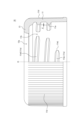
図1に示すように、本実施形態に係るねじキャップ付き容器100は、内容物を収容する収容空間S(図4参照)を有する容器本体20と、容器本体20の口部22(図4参照)にねじ係合により装着されたねじキャップ10と、ねじキャップ10によって口部22に装着されたポンプ30と、ポンプ30から上方に延びるステムに固定されたノズルヘッド40とを備えている。ノズルヘッド40には、内容物を噴出させるノズル41が設けられている。
As shown in FIG. 1, the screw-capped
図2に示すように、本実施形態に係るねじキャップ付き容器100を構成するねじキャップ10は、外周面に雄ねじ部22aが形成された口部22(図4参照)を有する容器本体20に装着され、口部22を径方向外側から囲む周壁11と、周壁11の上端部を閉塞する天壁13とを備えている。
As shown in FIG. 2, the
周壁11の内周面には、口部22の雄ねじ部22aにねじ係合する雌ねじ部11aが設けられている。本実施形態において、雌ねじ部11aは、図2及び図3に示すように、周方向4箇所に間欠部11bを設けた間欠ねじとして構成されている。図3の例では、1周内における間欠部11bを除いたねじ部の割合は約80%である。
The inner peripheral surface of the
天壁13には、図2及び図3に示すように、天壁開口13aが設けられている。天壁開口13aは平面視で略円形状を備えており、図4に例示するように、この天壁開口13aを通して、ポンプ30のシリンダ31から上方に向けて立設部を突出させて、ノズルヘッド40と連結させることができる。
As shown in Figures 2 and 3, the
ねじキャップ10に設けられた雌ねじ部11aは、1条ねじであり、雌ねじ部11aを雄ねじ部22aに対して中心軸線O周りに1回転させたときに中心軸線Oに沿って進む距離(リード)が、隣り合うねじの距離(ピッチ)に等しい。また、雌ねじ部11aの内径は、図2に表れていない雌ねじ部11aの上端部(口部22の雄ねじ部22aと係合している部分の上端部)から下方に向かって徐々に小さくなるように形成されている。したがって、図2に示す下端部11eLの内径が、雌ねじ部11aの上端部の内径よりも小さくなるように構成されている。
The
本実施形態では、雌ねじ部11aのねじ部が周方向の全周に形成されていると仮定した場合にそのねじ部の内径が下方に向かって徐々に連続的に小さくなるように構成されている。実際には、本実施形態では雌ねじ部11aに間欠部11bを設けているため、間欠部11bを介して隣り合うねじ部の端部同士は、下方側のねじ部の内径の方が小さく形成されている。
In this embodiment, assuming that the female threaded
本実施形態では、雌ねじ部11aの上端部よりも上方の無効ねじ部11tは、図4に示すように、有効ねじ部(雌ねじ部11aの上端部と下端部11eLの間のねじ部)よりも内径が小さく雄ねじ部22aがねじ係合しにくい構成とされている。
In this embodiment, the
なお、雌ねじ部11aの下端部11eLは、雌ねじ部11aの有効ねじ部の下端部を意味するものとする。
The lower end 11eL of the
従来の雌ねじは、下方向(ねじ係合を解除する方向)に向かって雌ねじ部の内径が大きくなるように構成されていたため、ねじ係合を解除していく過程で係合し合う雄ねじ部の谷の径と雌ねじ部の内径との差が大きくなり、ねじ係合の解除に必要なトルクが、係合するねじ山の数の減少割合よりも顕著に低下していく。これによって、ねじ係合を解除するために雌ねじ部を雄ねじ部に対して周方向に回転させると、すぐにねじ係合が解除されてしまい、利用者が意図しないキャップの脱落等が発生することがあった。 Conventional female threads are configured so that the inner diameter of the female thread increases in the downward direction (the direction in which the threaded engagement is released). As a result, the difference between the root diameter of the male thread and the inner diameter of the female thread increases during the process of releasing the threaded engagement, and the torque required to release the threaded engagement decreases more significantly than the rate at which the number of engaged threads decreases. As a result, when the female thread is rotated circumferentially relative to the male thread to release the threaded engagement, the threaded engagement is immediately released, which can cause the cap to fall off unintentionally by the user.
これに対して本実施形態では、雌ねじ部11aの下端部11eLの内径が、雌ねじ部11aの上端部の内径よりも小さくなるように構成されているため、特に、雌ねじ部11aの下部において、雌ねじ部11aのねじ山と雄ねじ部22aのねじ山との接触面積を増加させて所望の残留トルクを発生させることができる。また、ねじ係合が完全に解除される直前まで、内径が小さい雌ねじ部11aの下端部11eLにおいて所定の残留トルクを発生させることができる。従って、ねじ係合が完全に解除されるまでの間に雄ねじ部22aに対して雌ねじ部11aが意図せず外れてしまうことを抑制することができる。
In contrast, in this embodiment, the inner diameter of the lower end 11eL of the
特に本実施形態では、雌ねじ部11aの巻数(雌ねじ部11aの上端部から下端部までの巻数)は1巻以上となっており、雌ねじ部11aの下端部11eLから上方に向かって半周分のねじ部11aLは、雌ねじ部11aの上端部から下方に向かって半周分のねじ部11aUよりも、同じ周方向位置で比較したときに、ねじ山が径方向内側にdだけ突出しており、内径が2dだけ小さくなるように構成されている(図2及び図4参照)。この構成の採用によって、主に雌ねじ部11aの下部の領域で雌ねじ部11aのねじ山と雄ねじ部22aのねじ山との接触面積を更に増加させて所望の残留トルクを発生させることができる。また、ねじ係合解除時のトルクの減少による意図しないねじキャップ10の脱落をより確実に抑制することができる。
In particular, in this embodiment, the number of turns of the
なお、ここで述べる「ねじ部の内径」とは、中心軸線Oを挟んで対向するねじ部が同じ突出量だけ径方向内側に突出していると仮定したときの対向するねじ部同士の最短距離であり、中心軸線Oとねじ部との最短距離の2倍の距離である。 The "inner diameter of the threaded portion" mentioned here is the shortest distance between the opposing threaded portions when it is assumed that the opposing threaded portions on either side of the central axis O protrude radially inward by the same amount, and is twice the shortest distance between the central axis O and the threaded portions.
また、ここで述べる、「雌ねじ部11aの巻数は1巻以上」とは、雌ねじ部11aが、上端部から下端部11eLまで間欠部11bを含めて1周分以上のねじ部を有する、という意味である。雌ねじ部11aが2条ねじである場合、雌ねじ部11aは2条ねじを構成する2つのねじ部(ねじ山)をそれぞれ間欠部11bを含めて1周分含んでいる、という意味である。なお、雌ねじ部11aは、3条以上の多条ねじであってもよい。
In addition, the phrase "the number of turns of the
本実施形態にように、雌ねじ部11aの内径が、下方に向かって徐々に小さくなるように構成した場合では、残留トルクを600N・cmから639N・cmへと約6.5%増加させることができる。
In this embodiment, when the inner diameter of the
なお、本実施形態では、ねじキャップ10の周壁11を下方に向けて僅かに径方向外側に拡径するように構成し、雌ねじ部11aの内径を、雌ねじ部11aの上端部から下方に向かって徐々に小さくなるように形成したが、この態様には限定されない。例えば、ねじキャップ10の周壁11を下方に向けて径方向外側に拡径するように構成するとともに雌ねじ部11aの上端部から下方に向かってねじ部の内径が略同一になるように構成することによって、雌ねじ部11aのねじ山の高さが雌ねじ部11aの上端部から下方に向かって徐々に大きくなるように構成してもよい。この構成によって、雌ねじ部11aの上端部から下端部11eLまで、雄ねじ部22aと雌ねじ部11aのねじの係合(当接)の度合いを略同一にすることができる。なお、ねじ山の高さは、「(ねじ山の谷の径-ねじ山の内径)/2」で表すことができる。この構成であっても、従来技術の間欠ねじに対して、残留トルクの減少を抑制することができる。
In this embodiment, the
また、ねじキャップ10の周壁11を下方に向けて径方向外側に拡径するように構成するとともに、雌ねじ部11aの下端部11eLから上方に向かって半周分のねじ部11aLと雌ねじ部11aの上端部から下方に向かって半周分のねじ部11aUとが、同じ周方向位置で比較したときに内径が略同一になるように構成することによって、雌ねじ部11aの下端部11eLから上方に向かって半周分のねじ部11aLが、雌ねじ部11aの上端部から下方に向かって半周分のねじ部11aUよりも、同じ周方向位置で比較したときに、ねじ山の高さが高くなるように構成してもよい。
The
また、ねじキャップ10の周壁11を下方に向けて径方向外側に拡径するように構成するとともに、雌ねじ部11aの上端部のねじ部の内径と雌ねじ部11aの下端部11eLのねじ部の内径とが略同一になるように構成することによって、雌ねじ部11aの下端部11eLが雌ねじ部11aの上端部よりも、ねじ山の高さが高くなるように構成してもよい。
The
なお、本実施形態では、雌ねじ部11aの有効ねじ部(雌ねじ部11aの上端部から下端部11eLまでのねじ部)の巻数は約1.2巻である。
In this embodiment, the number of turns of the effective thread portion of the
本実施形態にかかるねじキャップ10は、周壁11の外周面に、縦方向に延びる平目ローレット11dが形成されている。これによって、ねじキャップ10の周壁11を把持する際の利用者の指等と周壁11との間の摩擦力を大きくすることができる。したがって、利用者は、ねじキャップ10を中心軸線O周りに回転させて雄ねじ部22aと雌ねじ部11aとのねじ係合を解除させるための力をより効率よく伝達することができる。
The
本実施形態に係るねじキャップ10は、図4に示すように、例えば、ノズル付きポンプを容器本体20の口部22に装着するために用いることができる。図4において、ポンプを構成するシリンダ31の上端部から径方向外側に延びるフランジ部31aが、パッキン31bとともに口部22の上端部とねじキャップ10の天壁13との間に挟持されている。
As shown in Fig. 4, the
なお、ねじキャップ10の用途は図4に示すものに限定されず、例えば、口部22を閉塞する蓋体として用いるようにしてもよい。その場合、ねじキャップ10は、天壁13に天壁開口13aが設けられていなくてもよい。
The use of the
本実施形態に係るねじキャップ10は、例えば合成樹脂製とすることができる。そして、ねじキャップ10を例えば射出成形によって形成する場合には、金型のコアが径方向内側にスライドするスライドコアを用いることによって、間欠部11bを有する雌ねじ部11aを比較的容易に形成することができる。スライドコアを用いることによって、従来の雌ねじ部を備えたねじキャップを形成する場合のように、コアを回転させながらキャビティから取り外す必要がないので、成形サイクルが短くなるほか、抜き勾配を設けておく必要がない。従って、本実施形態のように、雌ねじ部11aの内径が雌ねじ部11aの上端部から下方に向かって徐々に小さくなるような形状を比較的容易に形成することができる。
The
以上述べたように、本実施形態は、外周面に雄ねじ部22aが形成された筒状の口部22と、口部22に肩部24を介して連なり内容物の収容空間Sを形成する胴部23と、胴部23の下端部を閉塞する底部25とを有する容器本体20と、口部22にねじ係合により装着されるねじキャップ10とを備えるねじキャップ付き容器100であって、ねじキャップ10は、口部22を径方向外側から囲む周壁11を備え、周壁11の内周面には、雄ねじ部22aにねじ係合する雌ねじ部11aが設けられ、雌ねじ部11aは、周方向に間欠的に設けられており、雌ねじ部11aの下端部11eLにおけるねじ山の高さは、雌ねじ部11aの上端部におけるねじ山の高さよりも高くなるように構成した。このような構成の採用によって、特に、雌ねじ部11aの下部において、雌ねじ部11aのねじ山と雄ねじ部22aのねじ山との接触面積を増加させて所望の残留トルクを発生させることができる。また、ねじ係合が完全に解除される直前まで、ねじ山の高さが高い雌ねじ部11aの下端部11eLにおいて所定の残留トルクを発生させることができる。従って、ねじ係合が完全に解除されるまでの間に雌ねじ部11aが意図せず雄ねじ部22aから外れてしまうことを抑制することができる。
As described above, this embodiment is a container with a
また、本実施形態では、雌ねじ部11aの巻数は1巻以上であるように構成した。このような構成の採用によって、有効ねじ部の長さを十分に確保して、ねじキャップ10を容器本体20の口部22に装着したときの残留トルクを確保し易くすることができる。
In addition, in this embodiment, the number of turns of the
また、本実施形態では、雌ねじ部11aの下端部11eLから上方に向かって半周分のねじ部11aLは、雌ねじ部11aの上端部から下方に向かって半周分のねじ部11aUよりも、同じ周方向位置で比較したときのねじ山の高さが高くなるように構成した。このような構成の採用によって、雌ねじ部11aのねじ山と雄ねじ部22aのねじ山との接触面積を更に増加させて所望の残留トルクを発生させることができる。また、ねじ係合解除時の残留トルクの減少による意図しないねじキャップ10の脱落をより確実に抑制することができる。
In addition, in this embodiment, the threaded portion 11aL extending upward from the lower end 11eL of the female threaded
本開示を諸図面や実施例に基づき説明してきたが、当業者であれば本開示に基づき種々の変形や修正を行うことが容易であることに注意されたい。従って、これらの変形や修正は本発明の範囲に含まれることに留意されたい。例えば、各構成部に含まれる機能などは論理的に矛盾しないように再配置可能であり、複数の構成部を1つに組み合わせたり、或いは分割したりすることが可能である。本発明の範囲にはこれらも包含されるものと理解されたい。 Although the present disclosure has been described based on various drawings and examples, it should be noted that a person skilled in the art would be able to easily make various modifications and corrections based on the present disclosure. Therefore, it should be noted that these modifications and corrections are included in the scope of the present invention. For example, the functions contained in each component can be rearranged so as not to cause logical inconsistencies, and multiple components can be combined into one or divided. It should be understood that these are also included in the scope of the present invention.
例えば、雌ねじ部11aの巻数は1巻以上(約1.2巻)としているが、この態様には限定されず、雌ねじ部11aの巻数は、2巻以上であってもよい。
For example, the number of turns of the
また、本実施形態では、雌ねじ部11aの1周分のねじ部に、間欠部11bが4箇所設けられるように構成したが、この態様には限定されない。1周分のねじ部内に設ける間欠部11bの数は3箇所以下であってもよいし、5箇所以上であってもよい。また、間欠部11bを設ける周方向位置は、間欠部11bごとに異なっていてもよい。また、1周分のねじ部内に間欠部11bを含まない箇所があってもよく、雌ねじ部11aが全体として少なくとも1つの間欠部11bを備えていればよい。
In addition, in this embodiment, the
また、本実施形態では、雌ねじ部11aは、下方に向かって内径が徐々に小さくなるように構成されていることが最も好ましい旨記載したが、この態様には限定されない。雌ねじ部11aの下端部11eLのねじ山の高さが雌ねじ部11aの上端部のねじ山の高さよりも高く構成されていればよい。
In addition, in this embodiment, it has been described that it is most preferable that the
10 ねじキャップ
11 周壁
11a 雌ねじ部
11aL 雌ねじ部の下端部から上方に向かって半周分のねじ部
11aU 雌ねじ部の上端部から下方に向かって半周分のねじ部
11b 間欠部
11d 平目ローレット
11eL 雌ねじ部の下端部
11t 無効ねじ部
13 天壁
13a 天壁開口
20 容器本体
22 口部
22a 雄ねじ部
23 胴部
24 肩部
25 底部
30 ポンプ
31 シリンダ
31a フランジ部
31b パッキン
40 ノズルヘッド
41 ノズル
100 ねじキャップ付き容器
O 中心軸線
S 収容空間
REFERENCE SIGNS
Claims (1)
前記口部にねじ係合により装着されるねじキャップと
を備えるねじキャップ付き容器であって、
前記ねじキャップは、
前記口部を径方向外側から囲む周壁を備え、
前記周壁の内周面には、前記雄ねじ部にねじ係合する雌ねじ部が設けられ、
前記雌ねじ部は、周方向に間欠的に設けられており、
前記雌ねじ部の下端部におけるねじ山の高さは、前記雌ねじ部の上端部におけるねじ山の高さよりも高く、
前記雌ねじ部の巻数は1巻以上であり、
前記雌ねじ部の下端部から上方に向かって半周分のねじ部は、前記雌ねじ部の上端部から下方に向かって半周分のねじ部よりも、同じ周方向位置で比較したときのねじ山の高さが高いことを特徴とするねじキャップ付き容器。 a container body having a cylindrical mouth portion having a male screw portion formed on an outer peripheral surface thereof, a body portion connected to the mouth portion and forming a storage space for the contents, and a bottom portion closing a lower end portion of the body portion;
A screw cap is attached to the mouth by threaded engagement.
The screw cap is
A peripheral wall is provided surrounding the mouth portion from the radially outer side,
An internal thread portion is provided on an inner peripheral surface of the peripheral wall and is threadedly engaged with the external thread portion,
The female thread portion is provided intermittently in a circumferential direction,
The height of the thread at the lower end of the female thread portion is higher than the height of the thread at the upper end of the female thread portion,
The number of turns of the female thread portion is 1 or more,
A container with a screw cap, characterized in that the thread height of the half-circumference of the thread portion extending upward from the lower end of the female thread portion is higher than the thread height of the half-circumference of the thread portion extending downward from the upper end of the female thread portion when compared at the same circumferential position .
Priority Applications (1)
| Application Number | Priority Date | Filing Date | Title |
|---|---|---|---|
| JP2020199223A JP7588935B2 (en) | 2020-11-30 | 2020-11-30 | Container with screw cap |
Applications Claiming Priority (1)
| Application Number | Priority Date | Filing Date | Title |
|---|---|---|---|
| JP2020199223A JP7588935B2 (en) | 2020-11-30 | 2020-11-30 | Container with screw cap |
Publications (2)
| Publication Number | Publication Date |
|---|---|
| JP2022086922A JP2022086922A (en) | 2022-06-09 |
| JP7588935B2 true JP7588935B2 (en) | 2024-11-25 |
Family
ID=81894570
Family Applications (1)
| Application Number | Title | Priority Date | Filing Date |
|---|---|---|---|
| JP2020199223A Active JP7588935B2 (en) | 2020-11-30 | 2020-11-30 | Container with screw cap |
Country Status (1)
| Country | Link |
|---|---|
| JP (1) | JP7588935B2 (en) |
Citations (2)
| Publication number | Priority date | Publication date | Assignee | Title |
|---|---|---|---|---|
| JP2015030483A (en) | 2013-07-31 | 2015-02-16 | 株式会社吉野工業所 | Container with cap |
| WO2016151746A1 (en) | 2015-03-24 | 2016-09-29 | サントリーホールディングス株式会社 | Cap structure for resin container |
Family Cites Families (2)
| Publication number | Priority date | Publication date | Assignee | Title |
|---|---|---|---|---|
| JPS579239Y2 (en) * | 1978-12-13 | 1982-02-22 | ||
| JPS56131009U (en) * | 1980-03-07 | 1981-10-05 |
-
2020
- 2020-11-30 JP JP2020199223A patent/JP7588935B2/en active Active
Patent Citations (2)
| Publication number | Priority date | Publication date | Assignee | Title |
|---|---|---|---|---|
| JP2015030483A (en) | 2013-07-31 | 2015-02-16 | 株式会社吉野工業所 | Container with cap |
| WO2016151746A1 (en) | 2015-03-24 | 2016-09-29 | サントリーホールディングス株式会社 | Cap structure for resin container |
Also Published As
| Publication number | Publication date |
|---|---|
| JP2022086922A (en) | 2022-06-09 |
Similar Documents
| Publication | Publication Date | Title |
|---|---|---|
| US20150321798A1 (en) | Container sealing device | |
| JP6084542B2 (en) | Cap with inner plug | |
| CN113226940A (en) | Safety cap bottle assembly | |
| JP6138651B2 (en) | Cap with inner plug | |
| CN102470959B (en) | Child resistant closure with stacking position | |
| JP2016222288A (en) | Double container | |
| JP7588935B2 (en) | Container with screw cap | |
| RU2129512C1 (en) | Bottle cap | |
| JP6050993B2 (en) | Pouring container with overcap | |
| JP6177677B2 (en) | Container sealing device | |
| JP7154981B2 (en) | corkscrew cap | |
| JP5560395B2 (en) | Container with inner stopper | |
| EP3077300B1 (en) | Closure cap | |
| JP6144146B2 (en) | Container with cap | |
| JP6017981B2 (en) | Cap with inner plug | |
| JP4954695B2 (en) | Refill container | |
| JPWO2018020532A1 (en) | container | |
| JP2001158456A (en) | Liquid storage container and refill container for the container | |
| JP6635898B2 (en) | Safety cap | |
| JP6220538B2 (en) | Bottle | |
| JP7175846B2 (en) | Feeding container | |
| JP5593135B2 (en) | Container with inner stopper | |
| JP5529633B2 (en) | Container with inner stopper | |
| JP7246831B2 (en) | pouring cap | |
| JP7713405B2 (en) | Transfer stopper cap |
Legal Events
| Date | Code | Title | Description |
|---|---|---|---|
| A621 | Written request for application examination |
Free format text: JAPANESE INTERMEDIATE CODE: A621 Effective date: 20230607 |
|
| A977 | Report on retrieval |
Free format text: JAPANESE INTERMEDIATE CODE: A971007 Effective date: 20231227 |
|
| A131 | Notification of reasons for refusal |
Free format text: JAPANESE INTERMEDIATE CODE: A131 Effective date: 20240116 |
|
| A02 | Decision of refusal |
Free format text: JAPANESE INTERMEDIATE CODE: A02 Effective date: 20240618 |
|
| A521 | Request for written amendment filed |
Free format text: JAPANESE INTERMEDIATE CODE: A523 Effective date: 20240912 |
|
| A911 | Transfer to examiner for re-examination before appeal (zenchi) |
Free format text: JAPANESE INTERMEDIATE CODE: A911 Effective date: 20240924 |
|
| TRDD | Decision of grant or rejection written | ||
| A01 | Written decision to grant a patent or to grant a registration (utility model) |
Free format text: JAPANESE INTERMEDIATE CODE: A01 Effective date: 20241112 |
|
| A61 | First payment of annual fees (during grant procedure) |
Free format text: JAPANESE INTERMEDIATE CODE: A61 Effective date: 20241112 |
|
| R150 | Certificate of patent or registration of utility model |
Ref document number: 7588935 Country of ref document: JP Free format text: JAPANESE INTERMEDIATE CODE: R150 |