JP7588933B2 - Medical Materials - Google Patents
Medical Materials Download PDFInfo
- Publication number
- JP7588933B2 JP7588933B2 JP2020190934A JP2020190934A JP7588933B2 JP 7588933 B2 JP7588933 B2 JP 7588933B2 JP 2020190934 A JP2020190934 A JP 2020190934A JP 2020190934 A JP2020190934 A JP 2020190934A JP 7588933 B2 JP7588933 B2 JP 7588933B2
- Authority
- JP
- Japan
- Prior art keywords
- catheter
- defect
- tube
- cable
- tubular
- Prior art date
- Legal status (The legal status is an assumption and is not a legal conclusion. Google has not performed a legal analysis and makes no representation as to the accuracy of the status listed.)
- Active
Links
- 239000012567 medical material Substances 0.000 title claims description 38
- 230000007547 defect Effects 0.000 claims description 164
- 238000005304 joining Methods 0.000 claims description 4
- 239000000463 material Substances 0.000 description 144
- 239000000835 fiber Substances 0.000 description 17
- 208000013914 atrial heart septal defect Diseases 0.000 description 15
- 208000035478 Interatrial communication Diseases 0.000 description 14
- 206010003664 atrial septal defect Diseases 0.000 description 14
- 230000008859 change Effects 0.000 description 12
- 210000005246 left atrium Anatomy 0.000 description 12
- 210000005245 right atrium Anatomy 0.000 description 12
- 230000001746 atrial effect Effects 0.000 description 11
- 210000003157 atrial septum Anatomy 0.000 description 9
- 230000007774 longterm Effects 0.000 description 8
- 238000009940 knitting Methods 0.000 description 7
- 229910045601 alloy Inorganic materials 0.000 description 6
- 239000000956 alloy Substances 0.000 description 6
- 238000000034 method Methods 0.000 description 6
- 238000001356 surgical procedure Methods 0.000 description 6
- 235000017060 Arachis glabrata Nutrition 0.000 description 5
- 241001553178 Arachis glabrata Species 0.000 description 5
- 235000010777 Arachis hypogaea Nutrition 0.000 description 5
- 235000018262 Arachis monticola Nutrition 0.000 description 5
- 229910052751 metal Inorganic materials 0.000 description 5
- 239000002184 metal Substances 0.000 description 5
- 235000020232 peanut Nutrition 0.000 description 5
- 230000009471 action Effects 0.000 description 4
- 239000008280 blood Substances 0.000 description 4
- 210000004369 blood Anatomy 0.000 description 4
- 229920001577 copolymer Polymers 0.000 description 4
- 239000004744 fabric Substances 0.000 description 4
- 210000002837 heart atrium Anatomy 0.000 description 4
- 230000007257 malfunction Effects 0.000 description 4
- 238000002560 therapeutic procedure Methods 0.000 description 4
- 208000008883 Patent Foramen Ovale Diseases 0.000 description 3
- -1 knit shape Substances 0.000 description 3
- 230000014759 maintenance of location Effects 0.000 description 3
- 238000003825 pressing Methods 0.000 description 3
- YCKRFDGAMUMZLT-UHFFFAOYSA-N Fluorine atom Chemical compound [F] YCKRFDGAMUMZLT-UHFFFAOYSA-N 0.000 description 2
- FYYHWMGAXLPEAU-UHFFFAOYSA-N Magnesium Chemical compound [Mg] FYYHWMGAXLPEAU-UHFFFAOYSA-N 0.000 description 2
- TZCXTZWJZNENPQ-UHFFFAOYSA-L barium sulfate Chemical compound [Ba+2].[O-]S([O-])(=O)=O TZCXTZWJZNENPQ-UHFFFAOYSA-L 0.000 description 2
- 210000004204 blood vessel Anatomy 0.000 description 2
- 238000005520 cutting process Methods 0.000 description 2
- 238000010586 diagram Methods 0.000 description 2
- 239000003814 drug Substances 0.000 description 2
- 229940079593 drug Drugs 0.000 description 2
- 230000000694 effects Effects 0.000 description 2
- 210000003191 femoral vein Anatomy 0.000 description 2
- 229910052731 fluorine Inorganic materials 0.000 description 2
- 239000011737 fluorine Substances 0.000 description 2
- 210000004013 groin Anatomy 0.000 description 2
- 210000005240 left ventricle Anatomy 0.000 description 2
- 210000004072 lung Anatomy 0.000 description 2
- 229910052749 magnesium Inorganic materials 0.000 description 2
- 239000011777 magnesium Substances 0.000 description 2
- 229910001000 nickel titanium Inorganic materials 0.000 description 2
- BASFCYQUMIYNBI-UHFFFAOYSA-N platinum Chemical compound [Pt] BASFCYQUMIYNBI-UHFFFAOYSA-N 0.000 description 2
- 210000005241 right ventricle Anatomy 0.000 description 2
- 229910001285 shape-memory alloy Inorganic materials 0.000 description 2
- 239000010935 stainless steel Substances 0.000 description 2
- 229910001220 stainless steel Inorganic materials 0.000 description 2
- 238000009941 weaving Methods 0.000 description 2
- 239000002759 woven fabric Substances 0.000 description 2
- 206010003226 Arteriovenous fistula Diseases 0.000 description 1
- 102000008186 Collagen Human genes 0.000 description 1
- 108010035532 Collagen Proteins 0.000 description 1
- 206010010356 Congenital anomaly Diseases 0.000 description 1
- 208000012239 Developmental disease Diseases 0.000 description 1
- 108010010803 Gelatin Proteins 0.000 description 1
- CBENFWSGALASAD-UHFFFAOYSA-N Ozone Chemical compound [O-][O+]=O CBENFWSGALASAD-UHFFFAOYSA-N 0.000 description 1
- 239000002202 Polyethylene glycol Substances 0.000 description 1
- 229920000954 Polyglycolide Polymers 0.000 description 1
- 239000004372 Polyvinyl alcohol Substances 0.000 description 1
- 208000001910 Ventricular Heart Septal Defects Diseases 0.000 description 1
- HZEWFHLRYVTOIW-UHFFFAOYSA-N [Ti].[Ni] Chemical compound [Ti].[Ni] HZEWFHLRYVTOIW-UHFFFAOYSA-N 0.000 description 1
- 210000000709 aorta Anatomy 0.000 description 1
- 230000008901 benefit Effects 0.000 description 1
- 238000009954 braiding Methods 0.000 description 1
- 229920001436 collagen Polymers 0.000 description 1
- 201000010099 disease Diseases 0.000 description 1
- 208000037265 diseases, disorders, signs and symptoms Diseases 0.000 description 1
- 238000010894 electron beam technology Methods 0.000 description 1
- 238000005516 engineering process Methods 0.000 description 1
- 230000008175 fetal development Effects 0.000 description 1
- 229920000159 gelatin Polymers 0.000 description 1
- 239000008273 gelatin Substances 0.000 description 1
- 235000019322 gelatine Nutrition 0.000 description 1
- 235000011852 gelatine desserts Nutrition 0.000 description 1
- 238000002695 general anesthesia Methods 0.000 description 1
- PCHJSUWPFVWCPO-UHFFFAOYSA-N gold Chemical compound [Au] PCHJSUWPFVWCPO-UHFFFAOYSA-N 0.000 description 1
- 239000010931 gold Substances 0.000 description 1
- 229910052737 gold Inorganic materials 0.000 description 1
- 238000009998 heat setting Methods 0.000 description 1
- 238000003384 imaging method Methods 0.000 description 1
- 238000000338 in vitro Methods 0.000 description 1
- 238000001727 in vivo Methods 0.000 description 1
- 230000001788 irregular Effects 0.000 description 1
- JJTUDXZGHPGLLC-UHFFFAOYSA-N lactide Chemical compound CC1OC(=O)C(C)OC1=O JJTUDXZGHPGLLC-UHFFFAOYSA-N 0.000 description 1
- 210000004115 mitral valve Anatomy 0.000 description 1
- 238000012986 modification Methods 0.000 description 1
- 230000004048 modification Effects 0.000 description 1
- 229920005615 natural polymer Polymers 0.000 description 1
- 235000014571 nuts Nutrition 0.000 description 1
- 208000003278 patent ductus arteriosus Diseases 0.000 description 1
- 229910052697 platinum Inorganic materials 0.000 description 1
- 229920000747 poly(lactic acid) Polymers 0.000 description 1
- 229920002463 poly(p-dioxanone) polymer Polymers 0.000 description 1
- 229920001610 polycaprolactone Polymers 0.000 description 1
- 239000004632 polycaprolactone Substances 0.000 description 1
- 229920001223 polyethylene glycol Polymers 0.000 description 1
- 239000004633 polyglycolic acid Substances 0.000 description 1
- 229920002451 polyvinyl alcohol Polymers 0.000 description 1
- 210000001147 pulmonary artery Anatomy 0.000 description 1
- 210000003492 pulmonary vein Anatomy 0.000 description 1
- 239000002994 raw material Substances 0.000 description 1
- 238000007789 sealing Methods 0.000 description 1
- 229920002379 silicone rubber Polymers 0.000 description 1
- 239000004945 silicone rubber Substances 0.000 description 1
- 210000002784 stomach Anatomy 0.000 description 1
- 238000003860 storage Methods 0.000 description 1
- 229920001059 synthetic polymer Polymers 0.000 description 1
- 230000007704 transition Effects 0.000 description 1
- 210000000591 tricuspid valve Anatomy 0.000 description 1
- 210000003462 vein Anatomy 0.000 description 1
- 210000001631 vena cava inferior Anatomy 0.000 description 1
- 210000002620 vena cava superior Anatomy 0.000 description 1
- 201000003130 ventricular septal defect Diseases 0.000 description 1
Images


Landscapes
- Surgical Instruments (AREA)
Description
本発明は、生体組織に形成された欠損孔を治療するための医療用材料に関し、特に、カテーテルにセットされて血管内を通じて治療部位まで送り込まれて生体内に留置される医療用材料に関する。 The present invention relates to a medical material for treating defects formed in biological tissue, and in particular to a medical material that is set in a catheter, delivered to the treatment site through a blood vessel, and left in the living body.
人間の心臓は中隔という組織で左右の部屋が仕切られており、左右それぞれに心房と心室とがあり、右心房、右心室、左心房、左心室の2心房2心室で構成されている。このような構成の心臓において、胎児期の発達障害により、先天的に欠損孔と呼ばれる穴が、右心房と左心房とを隔てる心房中隔に開いている心房中隔欠損症(ASD:Atrial Septal Defect)という疾患がある。 The human heart is divided into left and right chambers by tissue called the septum, with each chamber having an atrium and a ventricle, making it a two-atrium, two-ventricle arrangement: the right atrium, the right ventricle, and the left atrium and left ventricle. In a heart with this arrangement, there is a condition called atrial septal defect (ASD), in which a congenital hole called a defect is created in the atrial septum that separates the right and left atria due to a developmental disorder during fetal development.
この心房中隔欠損症の治療としては、以下に示す2つの方法がある。ひとつは胸を切って行う外科手術、もうひとつが胸を切らずに、閉鎖栓を使ったカテーテル治療である。
外科手術(パッチ手術)は、人工心肺を使用し、開胸して、欠損孔をパッチにて閉じる。カテーテル治療は、カテーテルに閉鎖栓をセットし、カテーテルを血管内に挿入し、目的の位置(欠損孔)まで送り込んで、その後、閉鎖栓を放出し体内に留置する。このカテーテル治療では胸を切開しないで足の付け根の静脈(大腿静脈)から、細長く折り畳んだ閉鎖栓とよばれる小さな治具(デバイス)を心房中隔に開いた穴の位置まで送り込み、穴を塞ぐものである。このカテーテル治療の長所は、全身麻酔が必要な開胸手術をすることなく、足の付け根(そけい部)という目立たない場所から、ごく小さな皮膚の切開(数ミリ)で治療ができる点である。
There are two methods for treating this atrial septal defect: one is a surgical procedure that involves cutting the chest, and the other is catheter treatment that uses an occluder without cutting the chest.
In surgery (patch surgery), a heart-lung machine is used, the chest is opened, and the defect hole is closed with a patch. In catheter therapy, a closure plug is set in a catheter, the catheter is inserted into a blood vessel, and sent to the desired location (defect hole), after which the closure plug is released and left in the body. In this catheter therapy, a small, folded tool (device) called a closure plug is sent from a vein at the base of the leg (femoral vein) to the location of the hole in the atrial septum and closes the hole without opening the chest. The advantage of this catheter therapy is that it can be performed with a very small skin incision (a few millimeters) from an inconspicuous location such as the groin (groin), without the need for open-chest surgery, which requires general anesthesia.
特表2008-512139号公報(特許文献1)は、心房中隔欠損症のカテーテル治療に用いられるアセンブリ(閉鎖栓)を開示する。このアセンブリは、心臓の通路(欠損孔)を密閉する。このアセンブリは、通路の第一端の近位に配置するために使用される第一アンカー、通路の第二端の近位に配置するために使用される第二アンカー、および通路を通って伸び、第一および第二アンカーに結合するために使用される可撓性延長材を含む心臓の通路を密閉する閉鎖装置からなり、第二アンカーは可撓性延長材に対して移動可能で第一および第二アンカーの間の可撓性延長材の長さを変更し、閉鎖装置を心臓の通路に供給する供給システムからなり、供給装置はガイドカテーテルの内腔の中を移動するように設定され、第二アンカーの可撓性延長材に沿った運動を制御するワイヤーを含む。 JP2008-512139A (Patent Document 1) discloses an assembly (closure plug) used in catheter treatment of atrial septal defect. The assembly seals a passageway (defect hole) in the heart. The assembly comprises a closure device for sealing the passageway in the heart, including a first anchor used for placement proximal to a first end of the passageway, a second anchor used for placement proximal to a second end of the passageway, and a flexible extension member used for extending through the passageway and connecting to the first and second anchors, the second anchor being movable relative to the flexible extension member to change the length of the flexible extension member between the first and second anchors, and a supply system for supplying the closure device to the passageway in the heart, the supply device being set to move within the lumen of the guide catheter and including a wire for controlling the movement of the second anchor along the flexible extension member.
そして、この特許文献1において、卵円孔開存(PFO:Patent Foramen Ovale)閉鎖装置(閉鎖栓)は、左心房アンカー、右心房アンカー、テザーおよびロックを含み、左心房アンカー、テザーを介して左心房アンカーに結合する右心房アンカーおよびロックは心臓内に残留してPFOを密閉することが開示されている。
パッチ手術の場合には、人工心肺を使用し、また、侵襲性が高いため入院期間が長くなるという問題がある。カテーテル治療の場合には、人工心肺は使用せず、また、侵襲性も低いため入院期間も短く好ましい。
特許文献1に開示されるように、左心房アンカーおよび右心房アンカーは心臓内に残留する。そして、左心房アンカーおよび右心房アンカーは一つまたはそれ以上のアームを含み、アームはハブから放射状に外側に向かって伸びており、このアームは好適には二成分ニッケルチタン合金の圧延シートから形成されている。そして、これらの左心房アンカーおよび右心房アンカーを生体内で拡張させて欠損孔を塞ぐことになるが、アンカーの拡張を開始させると、容易には元に戻すことはできない。特許文献1に開示されているような、複雑な構造で、かつ、生体外からの操作が難しい、専用の取出し装置を用いてアンカー
を折りたたむことになる。
Patch surgery requires the use of a heart-lung machine and is highly invasive, which results in a long hospital stay. Catheter therapy does not require the use of a heart-lung machine and is less invasive, which results in a shorter hospital stay.
As disclosed in the patent, the left atrial anchor and the right atrial anchor remain in the heart. The left atrial anchor and the right atrial anchor include one or more arms that extend radially outward from a hub, preferably formed from a rolled sheet of a binary nickel-titanium alloy. The left atrial anchor and the right atrial anchor are expanded in vivo to close the defect, but once the expansion of the anchors begins, they cannot be easily restored. The anchors are collapsed using a specialized removal device, as disclosed in the patent, which has a complex structure and is difficult to operate from outside the body.
しかしながら、たとえば、アンカーが心房内の生体組織に引っ掛かり傷付ける等の事態になった場合には、このような専用の取出し装置でアンカーを折りたたむだけの時間的余裕がない場合もある。このような場合には、開胸手術に即座に切り換えざるを得ない。これでは、結局、侵襲性が高い開胸手術を受けることになるという問題点がある。
さらに、金属製の欠損孔閉鎖栓が体内に一生涯残存するため、遠隔期の不具合が懸念されるという問題点がある。
However, if the anchor gets caught in biological tissue inside the atrium and injures it, there may not be enough time to collapse the anchor with a dedicated retrieval device. In such a case, the patient must immediately switch to open-chest surgery, which is a highly invasive procedure.
Furthermore, since the metal defect plug remains in the body for the patient's lifetime, there is a concern that it may cause problems in the long term.
本発明は、従来技術の上記の問題点に鑑みて開発されたものであり、その目的とするところは、生体内の治療部位にて放出・留置できる低侵襲のカテーテル治療を、複雑な構造を備えず容易かつ確実な操作で可能となり、体内に残存しても遠隔期の不具合の可能性がほとんどない、医療用材料を提供することを目的とする。 The present invention was developed in consideration of the above-mentioned problems with the conventional technology, and its purpose is to provide a medical material that allows for minimally invasive catheter treatment that can be released and placed at a treatment site inside the body, can be easily and reliably operated without a complex structure, and has almost no risk of long-term problems even if it remains in the body.
上記目的を達成するため、本発明に係る医療用材料は以下の技術的手段を講じている。
すなわち、本発明に係る医療用材料は、生体吸収性を備えた線材を用いた編み目状組織の筒体と前記筒体に離脱可能に接合されたデリバリーケーブルとを含む医療用材料であって、前記筒体の略中央部の筒径が他の部分の筒径よりも小さい形状を備え、前記略中央部を中心にして前記筒体の長手方向の一端である第1の端部側の第1の筒部と他端である第2の端部側の第2の筒部とが形成され、前記第1の端部と前記第2の端部とが前記略中央部を中心にして離隔して前記他の部分の筒径が縮小されてカテーテルに前記医療用材料が収納された場合に前記第2の端部側が前記カテーテルの先端側となり、前記医療用材料は、前記第1の端部側から前記略中央部を介して前記第2の端部側まで通されたデリバリーケーブルを接合する接合部を前記第2の端部側に備え、前記デリバリーケーブルを前記第1の端部側から前記医療用材料の外部へ通すことが可能なように形成され、前記デリバリーケーブルは、生体外から操作することにより前記第1の端部を前記第2の端部側へ押圧することが可能な構成を備えていることを特徴とする。
In order to achieve the above object, the medical material according to the present invention employs the following technical measures.
That is, the medical material according to the present invention is a medical material including a tubular body of a knitted structure using a wire having bioabsorbability and a delivery cable detachably joined to the tubular body, the tubular body has a shape in which the tubular diameter at approximately the center is smaller than the tubular diameter of other parts, a first tubular portion on a first end side which is one end in the longitudinal direction of the tubular body and a second tubular portion on a second end side which is the other end are formed around the approximately center, the first end and the second end are separated from each other around the approximately center, and the tubular diameter of the other parts is reduced, so that the medical material is inserted into a catheter. When the medical material is stored, the second end becomes the tip side of the catheter, the medical material is provided with a joint on the second end side for joining a delivery cable that has been passed from the first end side through the approximate central portion to the second end side, the delivery cable is formed so as to be able to be passed from the first end side to the outside of the medical material, and the delivery cable is configured so as to be able to press the first end toward the second end side by operating it from outside the living body.
好ましくは、前記デリバリーケーブルは、ケーブル本体と、前記ケーブル本体に沿って摺動可能なように前記医療用材料から生体外まで前記ケーブル本体に被せられた外筒とを含み、前記外筒を生体外から押す操作により前記第1の端部を前記第2の端部側へ押圧するように構成することができる。
さらに好ましくは、前記カテーテルに前記デリバリーケーブルが接合された医療用材料が収納された場合に、前記外筒の生体外側の端部が生体外に出ている状態で前記外筒の生体内側の端部が前記第1の端部に当接するように構成することができる。
Preferably, the delivery cable includes a cable body and an outer tube that covers the cable body from the medical material to outside the body so as to be slidable along the cable body, and can be configured so that the first end is pressed toward the second end by pushing the outer tube from outside the body.
More preferably, when the medical material to which the delivery cable is joined is stored in the catheter, the end of the outer tube on the inside of the body can be configured to abut against the first end while the end of the outer tube on the outside of the body is protruding outside the body.
さらに好ましくは、前記接合部は、雌ネジが設けられた中空円筒形状物であって、前記デリバリーケーブルの先端側に設けられた雄ネジが前記雌ネジに螺合することにより接合され、前記接合部により前記デリバリーケーブルに接合された前記医療用材料の全体が前記カテーテルに収納されている状態で前記欠損孔閉鎖材が前記カテーテルの開口部の方向へ進むように前記デリバリーケーブルが操作されて前記カテーテルの先端から前記第2の筒部に続いて前記第1の筒部が前記カテーテルの外部へ出されることにより、前記第1の端部と前記第2の端部とが前記略中央部を中心にして接近して、前記医療用材料により閉鎖される欠損孔に対応した大きさまで前記他の部分の筒径が拡張された場合に生体外において、前記デリバリーケーブルの生体外側の端部が前記外筒の生体外側の端部よりも長く、前記外筒から露出した前記デリバリーケーブルの生体外側の端部側に、前記デリバリーケーブルを自転させることにより前記雄ネジと前記雌ネジとの螺合を解放して前記筒体から前記デリバリーケーブルを離脱させる手元操作治具が接続されたように構成することができる。 More preferably, the joint is a hollow cylindrical object provided with a female thread, and is joined by screwing a male thread provided on the tip side of the delivery cable into the female thread, and when the entire medical material joined to the delivery cable by the joint is housed in the catheter, the delivery cable is operated so that the defect closure material advances toward the opening of the catheter, and the first cylindrical portion is taken out of the catheter from the tip of the catheter, followed by the second cylindrical portion, so that the first end and the second end approach each other around the approximate center, and the cylindrical diameter of the other portion is expanded to a size corresponding to the defect hole to be closed by the medical material. In vitro, the end of the delivery cable outside the living body is longer than the end of the outer tube outside the living body, and a hand-operated tool that rotates the delivery cable on its own axis to release the male thread from the female thread and detach the delivery cable from the tube.
本発明の医療用材料によれば、生体内の治療部位にて放出・留置できる低侵襲のカテーテル治療を、複雑な構造を備えず容易かつ確実な操作で可能となる。さらに、本発明の医療用材料によれば、体内に残存しても遠隔期の不具合の可能性がほとんどない。 The medical material of the present invention enables minimally invasive catheter treatment that can be released and placed at a treatment site inside the body, with easy and reliable operation without a complex structure. Furthermore, the medical material of the present invention has almost no risk of long-term problems even if it remains in the body.
以下、本発明に係る医療用材料を、図面に基づき詳しく説明する。なお、以下においては、本発明に係る医療用材料の一例として、カテーテル治療に用いられる欠損孔閉鎖材について説明するが、その他の開口または通路、たとえば心室中隔欠損、動脈管開存等の心臓のその他の開口、および動静脈瘻等の生体のその他の部位(たとえば胃)の開口または通路の閉鎖にも適している。従って、本発明の実施の形態に係る欠損孔閉鎖材は、心房中隔欠損症の穴を閉鎖するための使用に限定されるものではない。また、本発明に係る医療用材料には、後述する編み目状組織の筒体(右心房側に配置される手元側の第1の筒部110と左心房側に配置される先端側の第2の筒部120とが略中央部130で介して接続された筒体)自体に加えて、この筒体に離脱可能に接合されたデリバリーケーブル500を含む場合がある。
The medical material according to the present invention will be described in detail below with reference to the drawings. In the following, a defect closure material used in catheter treatment will be described as an example of the medical material according to the present invention, but it is also suitable for closing other openings or passages, such as other openings in the heart, such as ventricular septal defect and patent ductus arteriosus, and openings or passages in other parts of the body (for example, the stomach), such as arteriovenous fistulas. Therefore, the defect closure material according to the embodiment of the present invention is not limited to use for closing holes in atrial septal defects. In addition, the medical material according to the present invention may include a cylinder of a knitted tissue (a cylinder in which a
さらに、以下の実施の形態においては、本発明に係る医療用材料の一例である欠損孔閉鎖材(閉鎖栓)100(以下において医療用材料100と記載する場合がある)の編み目状組織は生体吸収性繊維(線材の一例)を編成したものとして説明するが、本発明はこれに限定されるものではない。生体に形成された欠損孔を閉鎖するカテーテル治療ができる欠損孔閉鎖材であればよく、その編み目状組織も素材も、後述する第1の特徴~第2の特徴を備え第1の作用~第3の作用を発現するものであれば限定されるものではなく、たとえば素材は生体吸収性繊維以外の線材で編成されていても構わない。このような線材としては、(後述する形状保持部材による形状保持性とは異なる)欠損孔閉鎖材の形状保持性を備えるために、ある程度の硬度を備える線材であることが好ましい。 Furthermore, in the following embodiment, the mesh-like structure of the defect hole closure material (closure plug) 100 (hereinafter sometimes referred to as medical material 100), which is an example of the medical material according to the present invention, is described as being formed by weaving bioabsorbable fibers (an example of wire material), but the present invention is not limited to this. Any defect hole closure material that can perform catheter treatment to close a defect hole formed in a living body may be used, and the mesh-like structure and material are not limited as long as they have the first and second characteristics described below and exhibit the first to third actions, and for example, the material may be knitted with wire material other than bioabsorbable fibers. It is preferable that such wire material has a certain degree of hardness in order to provide the shape retention of the defect hole closure material (different from the shape retention provided by the shape retention member described below).
[基本的構成]
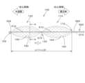
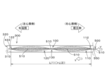
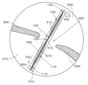
図1に本実施の形態に係る欠損孔閉鎖材100の全体図(第1の端部112と第2の端部122との距離が接近状態)を、図2にこの欠損孔閉鎖材100の別の全体図(第1の端部112と第2の端部122との距離が中間状態)を、図3にこの欠損孔閉鎖材100のさらに別の全体図(欠損孔閉鎖材100の全体がカテーテル300内に収納されて第1の端部112と第2の端部122との距離が離隔状態)を、図4にこの欠損孔閉鎖材100のさらに別の全体図(第2の筒部120がカテーテル300の外に出されて第1の筒部110がカテーテル300内に収納された状態)を、それぞれ示す。なお、この欠損孔閉鎖材100のカテーテル300への収納関係としては、図3はこの欠損孔閉鎖材100の全体がカテーテル300に収納されている状態を、図4はこの欠損孔閉鎖材100の半分(第1の筒部110側)がカテーテル300に収納されている状態を、それぞれ示す図である。
[Basic configuration]
FIG. 1 shows an overall view of defect
時間遷移的には、図3に示すカテーテル300の内部(内壁310により形成される空間)にその全体が収納されている欠損孔閉鎖材100を、第2の筒部120をカテーテル300の開口部320から矢示Y方向に出すと図4の状態になって、さらに第1の筒部110を矢示Y方向に出すと図1の状態になる。ここで、図2に示す欠損孔閉鎖材100の状態は、第1の端部112と第2の端部122との距離が中間状態であって仮想的な状態である。なお、「手元」と「根元」とは同義である。
In terms of time transition, the defect
これらの図に示すように、この欠損孔閉鎖材100は、大略的には、線材を用いた編み目状組織の筒体により形成され、この筒体の略中央部130の筒径が他の部分の筒径よりも小さい形状を備え、略中央部130を中心にして欠損孔閉鎖材100における筒体長手方向の第1の端部112側の第1の筒部110と他の端部(第2の端部122)側の第2の筒部120とが形成されている。
As shown in these figures, the defect
そして特徴的であるのは、第1の端部112と第2の端部122とが略中央部130を中心にして離隔して他の部分の筒径が縮小されてカテーテル300に欠損孔閉鎖材100が収納された場合に(図3に示す状態)第2の端部122側がカテーテル300の先端側となる。この場合において、この欠損孔閉鎖材100は、第1の端部112側から略中央部130を介して第2の端部122側まで通された操作ワイヤー500(以下においてデリバリーケーブル500と記載する場合がある)を接合する接合部422を第2の端部122側に備える。さらに、この欠損孔閉鎖材100は、このデリバリーケーブル500を第1の端部112側から欠損孔閉鎖材100の外部へ通すことが可能なように(たとえば、第1の端部112にデリバリーケーブル500のケーブル本体510が通る穴が)形成されている。
And what is characteristic is that when the
ここで、図10~図12に示すように、この接合部422は、雌ネジ424が設けられた中空円筒形状物(たとえば金属製)であって、デリバリーケーブル500のケーブル本体510の先端側に設けられた雄ネジ514が雌ネジ424に螺合することにより接合される。なお、生体内において、雌ネジ424に雄ネジ514が螺合する方向とは逆方向にケーブル本体510を回転(自転)させることにより、この螺合による接合を開放して、欠損孔閉鎖材100とデリバリーケーブル500とを離隔させることができる。
As shown in Figs. 10 to 12, the
ここで、図10~図12に示すように、この接合部422を形成する中空円筒形状物は、第1の筒部110側が開口して雌ネジ424が設けられて、デリバリーケーブル500のケーブル本体510の先端側に設けられた雄ネジ514と螺合可能であって、第1の筒部110側の反対側が閉じられている。
このように第1の筒部110側の反対側が閉じられていると、シース内で欠損孔閉鎖材を押し進めていくときにデリバリーケーブルの操作が容易になり、欠損孔閉鎖材が捻じれないようにすることができる点で好ましい。
Here, as shown in Figures 10 to 12, the hollow cylindrical object forming this joint 422 is open on the first
This is preferable in that closing the side opposite the first
なお、後述の[使用態様]において詳しく説明するが、この欠損孔閉鎖材100は、接合部422によりデリバリーケーブル500に接合された欠損孔閉鎖材100の全体がカテーテル300に収納されている状態で、デリバリーケーブル500が(欠損孔閉鎖材100がカテーテル300の開口部320の方向へ進むように)操作されてカテーテル300の先端から第2の筒部120に続いて第1の筒部110がカテーテル300の外部へ出されることにより、第1の端部112と第2の端部122とが略中央部130を中心にして接近して、欠損孔閉鎖材100により閉鎖される欠損孔に対応した大きさまで他の部分の筒径が拡張される。
As will be described in detail later in the section on [Use Mode], when the entire defect
このとき、第2の端部122側に接合部422が設けられ、この接合部422にデリバリーケーブル500の先端部が接合されているので、(デリバリーケーブル500の先端部に接合される接合部422が第1の端部122側に設けられている場合のように)第2の筒部120も第1の筒部110も押し出されるようにカテーテル300の外部へ出されるのではなく、引っ張られるようにカテーテル300の外部へ出される。押し出す場合に
は欠損孔閉鎖材100が捻れてしまい第1の端部112と第2の端部122とが略中央部130を中心にして適切に接近できずに欠損孔閉鎖材100により閉鎖される欠損孔に対応した大きさまで他の部分の筒径が適切に拡張しない場合があるが、引っ張る場合にはこのような欠損孔閉鎖材100が捻れることが抑制されて第1の端部112と第2の端部122とが略中央部130を中心にして適切に接近して欠損孔閉鎖材100により閉鎖される欠損孔に対応した大きさまで他の部分の筒径が適切に拡張することができる。
At this time, a joint 422 is provided on the
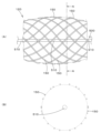
さらに、図5(A)に、この欠損孔閉鎖材100の部分的な側面図を、図5(B)に図2および図5(A)のA-A断面図を、それぞれ示す。なお、図5(B)は、欠損孔閉鎖材100(より詳しくは第2の筒部120)の断面図であるが、デリバリーケーブル500のケーブル本体510の断面を図示して、矢示A方向から視認できる生体吸収性繊維150の編み目を図示していない。また、図1~図5において、欠損孔閉鎖材100の内部に位置するデリバリーケーブル500のケーブル本体510の存在および生体吸収性繊維150の編み目についての理解を容易にするために紙面奥側に配置された生体吸収性繊維150については図示していないとともに、欠損孔閉鎖材100の外観形状についての理解を容易にするためにこの欠損孔閉鎖材100の外観形状を点線で示している部分がある。
Furthermore, FIG. 5(A) shows a partial side view of the defect
これらの図(特に図2)に示すように、この欠損孔閉鎖材100は、生体吸収性材料を用いた編み目状組織の2つの筒体(第1の筒部110および第2の筒部120)により形成されており、その形状はこのような2つの筒体から構成される、たとえば砂時計型、8の字型、2連の紡錘型(細長い棒状の真ん中が太く両端が細い紡錘形状物が2つ連続した形状)またはピーナッツ型(2粒の実を内包するピーナッツの殻の外観形状)と呼ばれるような形状を備える。このような形状を備える欠損孔閉鎖材100は、筒体の略中央部130の筒径が他の部分の筒径よりも小さくなるように略中央部130が絞られた形状を備える。すなわち、略中央部130を中心にして第1の端部112側の第1の筒部110と第2の端部122側の第2の筒部120とが形成されている。
As shown in these figures (particularly FIG. 2), the
なお、限定されるものではないが、この欠損孔閉鎖材100は、略中央部130の筒径を他の部分の筒径よりも小さい形状になるように、第1の筒部110および第2の筒部120が一体的に編まれて、この欠損孔閉鎖材100の全体形状としては2つの筒体から構成される砂時計型、8の字型、2連の紡錘型またはピーナッツ型に形成される。
この場合において、このような砂時計型、8の字型、2連の紡錘型またはピーナッツ型の型枠(3次元型紙)を用いて、その型枠に合わせて1本の生体吸収性繊維150を編成することによりこの欠損孔閉鎖材100の全体形状が形成される。さらに、限定されるものではないが、この欠損孔閉鎖材100は、第1の筒部110および第2の筒部120が一体的に編まれて略同一径の筒体を編成した後に熱セットすること等により、略中央部130の筒径が他の部分の筒径よりも小さく、かつ、略中央部130の筒径がデリバリーケーブル500のケーブル本体510の直径よりも大きい略中央部130を形成して、この欠損孔閉鎖材100の全体形状としては2つの筒体から構成される砂時計型、8の字型、2連の紡錘型またはピーナッツ型に形成されるようにしても構わない。
Although not limited thereto, the first
In this case, such an hourglass-shaped, figure-of-eight-shaped, double spindle-shaped, or peanut-shaped form (three-dimensional paper template) is used, and one
そして、詳しくは後述するが、このような形状を編み物で実現することにより、図3に示すカテーテル300の内部(内壁310により形成される空間)にその全体が収納されている欠損孔閉鎖材100を、第2の端部122側の接合部422にその先端部が接合されたデリバリーケーブル500が(欠損孔閉鎖材100がカテーテル300の開口部320の方向へ進むように)操作されてカテーテル300の先端の開口部320から第2の筒部120がカテーテル300の外部へ引っ張り出すように矢示Y方向に出されることにより、第2の筒部120がカテーテル300の内壁310により形成される空間から開放されて第2の筒部120が図4に示す状態になって、さらに、デリバリーケーブル500が(欠損孔閉鎖材100がカテーテル300の開口部320の方向へ(さらに)進むように)操作されてカテーテル300の先端の開口部320から第1の筒部110がカテーテル300の外部へ引っ張り出すように矢示Y方向に出されることにより、第2の筒部120に続いて第1の筒部110もカテーテル300の内壁310により形成される空間から開
放されて第1の筒部110(および第2の筒部120)が図1に示す状態になるという形状の変化(時間遷移的な形状の変化)を実現させることができる。
As will be described in detail later, by realizing such a shape by knitting, defect
図1に示すように、この欠損孔閉鎖材100がカテーテル300に収納されておらず空間に孤立して存在している場合には、第1の端部112と第2の端部122とが略中央部130を中心にして接近して、略中央部130以外の他の部分である第1の筒部110および第2の筒部120の筒径が拡張されている。拡張した筒径については、この欠損孔閉鎖材100により閉鎖される欠損孔に対応した大きさまで、(略中央部130以外の他の部分である)第1の筒部110および第2の筒部120の筒径が拡張されていることが特に好ましい。
As shown in FIG. 1, when the
そして、図3に示すように、この欠損孔閉鎖材100をカテーテル300に収納すること等により空間に孤立して存在しているのではなく径方向の自由が制限されている場合には、第1の端部112と第2の端部122とが略中央部130を中心にして離隔して、他の部分である第1の筒部110および第2の筒部120の筒径が縮小されている。縮小した筒径については、この欠損孔閉鎖材100が収納されるカテーテル300に対応した大きさまで(略中央部130以外の他の部分である)第1の筒部110および第2の筒部120の筒径が縮小されていることが特に好ましい。
As shown in FIG. 3, when the
なお、デリバリーケーブル500のケーブル本体510の径は、略中央部130の筒径よりも小さい。
このように、この欠損孔閉鎖材100を、たとえば、カテーテル300に収納して径方向の自由を制限したり、カテーテル300から引き出すようにしてカテーテル300の外部に出して径方向の自由を制限しないようにしたりして、欠損孔閉鎖材100における筒体の長手方向の第1の端部112と他の端部である第2の端部122とを離隔させたり(カテーテル300に収納したり)接近させたり(カテーテル300から引き出したり)することができる。この欠損孔閉鎖材100を、たとえばカテーテル300から引き出すようにしてカテーテル300の外部に出して径方向の自由を制限しないと図1に示すように、第1の端部112と第2の端部122とが接近して、略中央部130の他の部分の筒径(第1の筒部110および第2の筒部120における胴部分の筒径)が拡張され、カテーテル300に収納して径方向の自由を制限すると図3に示すように、第1の端部112と第2の端部122とが離隔して、略中央部130の他の部分の筒径(第1の筒部110および第2の筒部120における胴部分の筒径)が縮小される。
The diameter of cable
In this way, the defect
さらに、図4に示すように、カテーテル300から第2の筒部120を矢示Y方向に引き出すとカテーテル300の内壁310により形状が規制されていた(径方向の自由が制限されていた)第2の筒部120が自由に形状を変化でき、第2の筒部120における胴部分の筒径だけが拡張される。そして、さらに、カテーテル300から第1の筒部110を矢示Y方向に引き出すとカテーテル300の内壁310により形状が規制されていた(径方向の自由が制限されていた)第1の筒部110も自由に形状を変化でき、第1の筒部110における胴部分の筒径も拡張される。
Furthermore, as shown in FIG. 4, when the
そして、この欠損孔閉鎖材100においては、第1の筒部110および第2の筒部120は、生体吸収性繊維150の織物(目の粗いもの)、編み物、組み紐状織物、または、筒編み状編み物で構成されており、全体が編み目状組織とされている。ここで確認的に記載するが、この編み目状組織は編成により形成される編み物に限定されるものではなく、上述したように網戸のような目の粗い織り組織により網目状組織が形成されるものを含む。すなわち、編み目状と呼ばれる組織であっても網目状と呼ばれる組織であっても構わない。
In this
このように、基本的には、たとえば金属製(たとえばステンレス製)の金属片からなる接合部422を除いて、第1の筒部110および第2の筒部120は全て生体吸収性材料で構成されているために、接合部422を除く欠損孔閉鎖材100の全体が生体吸収性を備える(デリバリーケーブル500は本発明に係る医療用材料を構成するものではなく生体内に残存するものではないので材質は特に問わない)。さらに、欠損孔閉鎖材100の形状が変化することにより欠損孔を閉鎖する治療が行われるわけであるが、欠損孔閉鎖材
100のこのように生体内で形状が変化しても生体内組織を損傷することがないような、素材、編み目形状、繊維組織および繊維断面で欠損孔閉鎖材100が、接合部422を含めて、形成されている。
In this way, basically, the first
なお、通常、接合部422はたとえばステンレス等が用いられ生体吸収性を備えないが、後述するマグネシウムをベースとする合金を用いて生体吸収性を備えるようにしても構わない。接合部422に、生体吸収性を備える合金を使用するとレントゲン撮像に反応する点で有利であって、生体吸収性を備える合金を使用すると金属製部材が体内に一生涯残存しないことになるため遠隔期の不具合が懸念されるという問題点を生じない点で有利である。 Although the joint 422 is usually made of, for example, stainless steel and is not bioabsorbable, it may be made bioabsorbable by using a magnesium-based alloy, as described below. Using a bioabsorbable alloy for the joint 422 is advantageous in that it reacts to X-ray imaging, and using a bioabsorbable alloy is advantageous in that the metal component does not remain in the body for the rest of the body, eliminating the problem of concern about long-term malfunctions.
第1の筒部110および第2の筒部120を構成している生体吸収性繊維150は、たとえば、ポリグリコール酸、ポリラクチド(D、L、DL体)、ポリカプロラクトン、グリコール酸-ラクチド(D、L、DL体)共重合体、グリコール酸-ε-カプロラクトン共重合体、ラクチド(D、L、DL体)-ε-カプロラクトン共重合体、ポリ(p-ジオキサノン)、グリコール酸-ラクチド(D、L、DL体)-ε-カプロラクトン共重合体等から選択される少なくとも1種とされ、モノフィラメント糸、マルチフィラメント糸、撚糸、組み紐などのいずれかに加工した形態で使用されるが、モノフィラメント糸の形態で使用されるのが好ましい。
The
さらに、この生体吸収性繊維150の素材は、生体吸収性合金であっても構わない。このような生体吸収性合金の一例として、原材料としてマグネシウムをベースとする合金が挙げられる。
生体吸収性繊維150の直径は、0.001mm~1.5mm程度とされ、適用するカテーテル治療に適切な繊維径および種類が選定される。また、生体吸収性繊維150の断面は、生体内組織を損傷しないことを条件として、円、楕円、その他の異形(たとえば星形)などのいずれであってもよい。さらに、生体吸収性繊維150の表面は、プラズマ放電、電子線処理、コロナ放電、紫外線照射、オゾン処理等により親水化処理してもよい。また、生体吸収性繊維150は、X線不透過材(たとえば、硫酸バリウム、金チップ、白金チップ等)の塗布または含浸処理や、薬剤(たとえば、心房中隔欠損症のカテーテル治療に適した薬剤)の付着処理、コラーゲン、ゼラチン等の天然高分子あるいはポリビニルアルコール、ポリエチレングリコール等の合成高分子でコーティング処理してもよい。
Furthermore, the material of the
The diameter of the
第1の筒部110および第2の筒部120は、生体吸収性繊維150が、たとえば、モノフィラメント糸として所望される外径のシリコーン製ゴム管(図示省略)の回りに複数(たとえば、8口または12口)の給糸口をもつ組紐機を用いて組み紐状織物に製作され、または、丸編機(図示省略)で、略同一径の筒体の編み目状組織に編成される。編成後、上記したように、第1の筒部110および第2の筒部120との2つの筒体から構成される砂時計型、8の字型、2連の紡錘型またはピーナッツ型に形成される。第1の筒部110および第2の筒部120の筒径は、縮径した場合にカテーテル300の内径よりも小さく、拡径した場合に心房中隔欠損症のカテーテル治療に好適な大きさを備える。たとえば、拡径した場合の第1の筒部110および第2の筒部120の筒径は、5mm~80mm、好ましくは15mm~25mm程度である。また、第1の筒部110および第2の筒部120の長さ、ならびに、欠損孔閉鎖材100の編み目状組織の密度についても、心房中隔欠損症のカテーテル治療に好適な密度を備える。なお、第1の筒部110および第2の筒部120の筒径および長さは、同じである必要はなく、心房中隔欠損症のカテーテル治療に好適なように変更すれば良い。
The first
以上のように、本実施の形態に係る欠損孔閉鎖材100は、以下の特徴を備える。
(第1の特徴)略中央部130において絞られた第1の筒部110および第2の筒部120から構成される砂時計型、8の字型、2連の紡錘型またはピーナッツ型に形成されている。
(第2の特徴)第1の端部112側から略中央部130を介して第2の端部122側まで通された操作ワイヤー500を接合する接合部422を第2の端部122側(カテーテル300の先端側)に備え、このデリバリーケーブル500を第1の端部112側から欠損
孔閉鎖材100の外部へ通すことが可能なように形成されている。
As described above,
(First feature) The first
(Second feature) A joint 422 is provided on the
そして、第1の特徴および第2の特徴により、カテーテル300に収納されたこの欠損孔閉鎖材100に対して、カテーテル300から第2の筒部120をカテーテル300の外部へ出すとカテーテル300の内壁310により形状が規制されていた第2の筒部120が自由に形状を変化できて第2の筒部120における胴部分の筒径だけが拡張され、さらに、カテーテル300から第1の筒部110をカテーテル300の外部へ出すとカテーテル300の内壁310により形状が規制されていた第1の筒部110も自由に形状を変化できて第1の筒部110における胴部分の筒径も拡張される。そして、この欠損孔閉鎖材100により閉鎖される欠損孔に対応した大きさまで胴部分の筒径が拡張される
特に、この欠損孔閉鎖材100は、以下の作用を発現する点で、心房中隔欠損症のカテーテル治療に適している。
Then, due to the first and second features, when the second
(第1の作用)第1の端部112と第2の端部122とが略中央部130を中心にして離隔させて(第1の端部112と第2の端部122とが離隔するように互いに逆方向へ引っ張って)、他の部分である第1の筒部110および第2の筒部120の筒径を縮小させることにより、欠損孔閉鎖材100の筒径をカテーテル300の内径よりも細くして、カテーテル300にセットすることができる。
(第2の作用)第2の端部122側に接合部422が設けられ、この接合部422にデリバリーケーブル500の先端部が接合されているので、第2の筒部120も第1の筒部110も押し出されるようにカテーテル300の外部へ出されるのではなく、引っ張られるようにカテーテル300の外部へ出されるために、押し出す場合には欠損孔閉鎖材100が捻れてしまい第1の端部112と第2の端部122とが略中央部130を中心にして適切に接近できずに欠損孔閉鎖材100により閉鎖される欠損孔に対応した大きさまで他の部分の筒径が適切に拡張しなくなることを抑制して、引っ張ることによりこのように欠損孔閉鎖材100が捻れることが抑制されて第1の端部112と第2の端部122とが略中央部130を中心にして適切に接近して欠損孔閉鎖材100により閉鎖される欠損孔に対応した大きさまで他の部分の筒径が適切に拡張させることができる。これにより、右心房側に配置された第1の筒部110と左心房側に配置された第2の筒部120とが略中央部130を中心にして接近して、心房中隔に開いた穴を塞ぐことができる。
(First action) By separating the
(Second action) A joint 422 is provided on the side of
(第3の作用)この欠損孔閉鎖材100を構成する素材(接合部422を除く場合がある)は全て生体吸収性材料であるので、最終的に生体内に吸収されるので遠隔期の不具合の可能性がほとんどなくなる。
さらに、本発明の好ましい形態について以下に説明する。
この欠損孔閉鎖材100は、上述したように生体吸収性を備えた線材を用いた編み目状組織の筒体(右心房側に配置される手元側の第1の筒部110と左心房側に配置される先端側の第2の筒部120とが略中央部130で介して接続された筒体)自体に加えて、この筒体に離脱可能に接合されたデリバリーケーブル500(より詳しくはケーブル本体510および外筒550)とを含んで構成されることが好ましい。そして、このデリバリーケーブル500は、生体外から操作することにより手元側の第1の端部112を先端側の第2の端部122側へ押圧することが可能な構成を備えている。
(Third effect) All of the materials constituting this defect closure material 100 (except for the joint 422 in some cases) are bioabsorbable materials, and therefore are ultimately absorbed into the body, almost eliminating the possibility of malfunctions in the long term.
Further, preferred embodiments of the present invention will be described below.
As described above, this
より詳しくは、このデリバリーケーブル500は、ケーブル本体510と、このケーブル本体510に沿って摺動可能なように欠損孔閉鎖材100の筒体自体から生体外までケーブル本体510に被せられた外筒550とを含むように構成されることが好ましい。そして、この外筒550を生体外から押す操作により手元側の第1の端部112を先端側の第2の端部122側へ押圧することができる。
More specifically, the
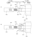
この外筒550の長さについては、デリバリーケーブル500が接合された欠損孔閉鎖材100の筒体自体がカテーテル300に収納された場合に(図3に示す状態において)、図6に示すように、外筒550の生体外側の端部が生体外に出ている状態で外筒550の生体内側の端部552が第1の端部112に当接する。これについて、図1~図4および図6を参照して、詳しく説明する。生体内側のデリバリーケーブル500のケーブル本体510における、先端側の接合部422(の手元側の接合部412側)の端面から、外筒550の生体内側の端面までの距離(以下において単に距離と記載する場合がある)は、最も短い場合を示す図1の状態でL(2)であって、最も長い状態を示す図3の状態でL(1)(>L(2))である。図2および図4に示す状態においては、その距離はL(1)~L(2)である。いずれの場合であっても、外筒550の生体内側の端部552が第1の端部112に当接することができているとともに、いずれの場合であっても、図6に示すように外筒550の生体外側の端部が生体外に出ている。そして、このような距離および位置関係ならびに筒体自体の形状変化を備えるために、いずれの状態であっても、外筒550の生体内側の端部552が第1の端部112に当接しているために、この外筒550を生体外から押す操作により手元側の第1の端部112を先端側の第2の端部122側へ押圧することができる。
Regarding the length of the
ここで、図10(A)に示すように、外筒550の生体内側の端部552が第1の端部112に当接していて、この外筒550を生体外から押す操作により手元側の第1の端部112を先端側の第2の端部122側へ押圧することができるものであることに替えて、図10(B)に示す構成であっても構わない。図10(B)に示すように、外筒550の生体内側の端部に鍔556が設けられていて、その鍔556の端面554が第1の端部112に当接していて、この外筒550を生体外から押す操作により手元側の第1の端部112を先端側の第2の端部122側へ押圧することができるものであっても構わない。このように構成することにより、生体内側の鍔556の端面554が第1の端部112に当接していて、この外筒550を生体外から押す操作によりこの鍔556の端面554が手元側の第1の端部112を先端側の第2の端部122側へ好適に(端部ではなく端面により第1の端部112を好適に)押圧することができる。なお、鍔556の最大外径は、カテーテル300の内径dよりも小さいことを確認的に記載する。
Here, as shown in Fig. 10(A), the
ここで、このように構成することによる顕著な作用効果について説明する。医療用材料100の筒体自体の素材として特に好ましく採用される生分解性材料は、ニッケルチタン合金のような形状記憶合金と比較すると、筒体の展開が遅い、または、展開性が悪い場合があり得る。このような場合において、図4に示すように、先端側の第2の筒部120を展開させた後に根元側の第1の筒部110を展開させる場合において(図4に示す状態からデリバリーケーブル500が(欠損孔閉鎖材100がカテーテル300の開口部320の方向へ(さらに)進むように)操作されてカテーテル300の先端の開口部320から第1の筒部110がカテーテル300の外部へ引っ張り出すように矢示Y方向に出されて第2の筒部120に続いて第1の筒部110もカテーテル300の内壁310により形成される空間から開放されて第1の筒部110(および第2の筒部120)が図1に示す状態になるという形状の変化(時間遷移的な形状の変化)を実現する場合において)、外筒550を生体外から押す操作により手元側の第1の端部112が先端側の第2の端部122側へ押圧されるために、第1の筒部110に生体分解性材料を採用したとしても、第1の筒部110を好ましく展開することができる。
Here, the remarkable effect of this configuration will be explained. Biodegradable materials, which are particularly preferably used as the material for the tubular body of the
ここで、本発明において、生体外から操作することにより手元側の第1の端部112を先端側の第2の端部122側へ押圧することは、上述した図4に示す場合(タイミング)に限定されるわけではない。
なお、この外筒550については、限定されるものではないが、たとえば、デリバリーケーブル500のケーブル本体の外径が1.5mmである場合に、、この外径1.5mmよりも大きい内径を備えた内径1.93mm(外径2.53mm)のフッ素チューブを被せることを、好ましく採用することができる。
Here, in the present invention, pressing the
Incidentally, although not limited to,
さらに以下の構成とすることも好ましい。筒体自体により閉鎖される欠損孔(たとえば右心房210と左心房230とを隔てる心房中隔250に欠損孔252)に対応した大きさまで他の部分の筒径が拡張された図1および図9に示す場合に、生体外において、図6に示すように、デリバリーケーブル500のケーブル本体510の生体外側の端部が外筒550の生体外側の端部よりも長く(外筒550からケーブル本体510が露出しており)、この露出したケーブル本体510の生体外側の端部側に、ケーブル本体510を自転させる雄ネジ514と雌ネジ424との螺合を解放して筒体からデリバリーケーブル50
0を離脱させる手元操作治具560が接続されていることも好ましい。ここで、雌ネジ424に雄ネジ514が螺合する方向が右ネジ(時計方向に自転させて進行して螺合)の場合には、この手元操作治具560を用いてその逆方向である反時計方向に自転させてケーブル本体510を回転(自転)させることにより、この螺合による接合を開放して、筒体自体とデリバリーケーブル500とを離隔させることができる。
1 and 9, in which the diameter of the other parts of the tube is expanded to a size corresponding to the defect hole that is closed by the tube body itself (for example,
It is also preferable that a hand-operated
なお、図6、図11および図12に示すように、この手元操作治具560は、ケーブル本体510の外径に対応した貫通孔を備えた断面形状が八角形の治具本体562と、その貫通孔に挿通されたケーブル本体510が治具本体562内で空転することを防止する止めネジ564とを備え、治具本体562を回転(自転)させることによりケーブル本体510を好適に回転(自転)させることができる構成を備える。なお、貫通孔は少なくとも止めネジ564の位置まで設けられていれば貫通していなくても構わない。
この欠損孔閉鎖材100を心房中隔欠損症のカテーテル治療に使用した場合について、図6~図9を参照して説明する。
6, 11 and 12, this
The use of this
[使用態様]
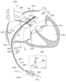
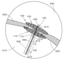
図6にこの欠損孔閉鎖材100を心房中隔欠損症のカテーテル治療に用いる場合の概念図を、図7~図9にこのカテーテル治療の手順を示す図6のB部の拡大図を、それぞれ示す。なお、以下においては、本実施の形態に係る欠損孔閉鎖材100の使用態様に特有の事項についてのみ説明し、一般的な事項については、公知の心房中隔欠損症のカテーテル治療と同じ説明であるのでここでの詳細な説明は繰り返さない。
[Usage]
Fig. 6 shows a conceptual diagram of the case where this defect
図6に示すように、人間の心臓200は、上大静脈および下大静脈に接続され全身から静脈血を受け入れる右心房210、肺動脈および三尖弁260を介して右心房210に接続され肺へ静脈血を送り出す右心室220、肺静脈に接続され肺からの動脈血を受け入れる左心房230、大動脈および僧帽弁270を介して左心房230に接続され全身へ動脈血を送り出す左心室240の2心房2心室で構成されている。心房中隔欠損症は、右心房210と左心房230とを隔てる心房中隔250に欠損孔252が開いているという疾患である。なお、図6においては、理解しやすくするために、カテーテル300の先端側(B部における破断線より先端側)を仮想線で示すことによりカテーテル300に収納された欠損孔閉鎖材100を実線にて示している。
As shown in FIG. 6, the
まず、生体外において、欠損孔252に対して適切な大きさまで拡張する欠損孔閉鎖材100の第1の端部112と第2の端部122とが離隔する方向へ引っ張って欠損孔閉鎖材100の筒径がカテーテル300の内径よりも細くして、カテーテル300にセットする。大腿静脈より欠損孔閉鎖材100が収納されたカテーテル300を挿入して(図3参照)、(欠損孔閉鎖材100が収納された)カテーテル300を(収納された欠損孔閉鎖材100とともに)矢示X(1)方向)へ移動させて、右心房210側より欠損孔252を通して左心房230側に欠損孔閉鎖材100が収納されたカテーテル300を近づける。
First, outside the body, the
図6および図7に示すように、欠損孔閉鎖材100の略中央部130が欠損孔252付近に対応するような位置で、欠損孔閉鎖材100を収納したカテーテル300を停止させる。デリバリーケーブル500が(欠損孔閉鎖材100がカテーテル300の開口部320の方向へ進むように)操作されて、生体内においては、先端側の接合部422にデリバリーケーブル500の先端部が接合されているのでカテーテル300から第2の筒部120が押し出されるようにカテーテル300の外部へ出されるのではなく、第2の筒部120が引っ張られるようにしてカテーテル300からカテーテル300の外部方向である矢示Y方向へ出される。そうすると、カテーテル300の内壁310により(径方向の)形状が規制されていた第2の筒部120が自由に形状を変化できて第2の筒部120における胴部分の筒径だけが、図8に示すように拡張される。
6 and 7, the
そして、さらに、デリバリーケーブル500が(欠損孔閉鎖材100がカテーテル300の開口部320の方向へ(さらに)進むように)操作されて、生体内においては、先端側の接合部422にデリバリーケーブル500の先端部が接合されているのでカテーテル300から第1の筒部110が押し出されるようにカテーテル300の外部へ出されるのではなく、第2の筒部120に続いて第1の筒部110が引っ張られるようにしてカテーテル300からカテーテル300の外部方向である矢示Y方向へ出される。そうすると、カテーテル300の内壁310により(径方向の)形状が規制されていた第1の筒部110も自由に形状を変化できて第1の筒部110における胴部分の筒径だけが、図9に示すように拡張される。
Then, the
すなわち、この欠損孔閉鎖材100の略中央部130が欠損孔252付近に対応するような位置で、デリバリーケーブル500を(欠損孔閉鎖材100がカテーテル300の開口部320の方向へ進むように)操作すると、左心房側に配置された第2の筒部120が先に拡張して、次いで右心房側に配置された第1の筒部110が後で拡張する。その結果、右心房210側に配置された第1の筒部110と左心房230側に配置された第2の筒部120とが略中央部130(欠損孔252)を中心にして接近するとともに、第1の筒部110および第2の筒部120が拡張する。最終的には、図9に示すように、第1の筒部110および第2の筒部120により心房中隔250をその両側から挟み込み、欠損孔閉鎖材100により、心房中隔250に開いた欠損孔252を塞ぐことができる。
That is, when the
ここで、この欠損孔閉鎖材100の略中央部130が欠損孔252付近に対応するような位置で、デリバリーケーブル500を(欠損孔閉鎖材100がカテーテル300の開口部320の方向へ進むように)操作して、左心房側に配置された第2の筒部120が先に拡張して、次いで右心房側に配置された第1の筒部110が後で拡張する場合において(すなわち、先端側の第2の筒部120を展開させた後に根元側の第1の筒部110を展開される場合において)、デリバリーケーブル500のケーブル本体510に被せられた外筒550を生体外から押す。この操作により手元側の第1の端部112が先端側の第2の端部122側へ押圧されるために、第1の筒部110に生体分解性材料を採用したとしても、先に展開する第2の筒部120に続いて、第1の筒部110を好ましく展開することができる。
Here, the
その後、体内において、雄ネジ514が雌ネジ424に螺合する方向とは逆方向に雄ネジ514が回転(自転)するようにケーブル本体510を回転(自転)させて、この螺合による欠損孔閉鎖材100とデリバリーケーブル500との接合を開放する。このとき、欠損孔252を塞ぐように設けられた欠損孔閉鎖材100は回転(自転)することはない。
Then, inside the body, the
このとき、生体外においては、図6に示すように、デリバリーケーブル500のケーブル本体510の生体外側の端部が外筒550の生体外側の端部よりも長く(外筒550からケーブル本体510が露出しており)、この露出したケーブル本体510の生体外側の端部側に、手元操作治具560が接続されている。雌ネジ424に雄ネジ514が螺合する方向が右ネジ(時計方向に自転させて進行して螺合)の場合には、この手元操作治具560をその逆方向である反時計方向に自転させてケーブル本体510を回転(自転)させることにより、この螺合による接合を好適に開放して、筒体自体とデリバリーケーブル500とを好適に離隔させることができる。
At this time, as shown in FIG. 6, outside the living body, the end of the
その後、矢示X(2)方向へ(デリバリーケーブル500を収納した)カテーテル300を移動させて、カテーテル300(およびデリバリーケーブル500)を生体外に取り出して治療が完了する。これにより、生体内には(正確には欠損孔252付近)には、全て生体吸収性材料から構成された欠損孔閉鎖材100(接合部422を除く場合がある)が留置される。このように生体内に留置された欠損孔閉鎖材100の素材は全て生体吸収性材料であるので(接合部422を除く場合がある)、最終的に生体内に吸収されるので遠隔期の不具合の可能性がほとんどない。
Then, the catheter 300 (with the
そして、このような使用態様において、操作ワイヤー500でカテーテル300から第1の筒部110を第2の筒部120に続けて矢示Y方向へ押し出す場合には欠損孔閉鎖材100が捻れてしまい第1の端部112と第2の端部122とが略中央部130を中心にして適切に接近できずに欠損孔閉鎖材100により閉鎖される欠損孔に対応した大きさまで他の部分の筒径が適切に拡張しない場合があるが、引っ張る場合にはこのような欠損孔閉鎖材100が捻れることが抑制されて第1の端部112と第2の端部122とが略中央
部130を中心にして適切に接近して欠損孔閉鎖材100により閉鎖される欠損孔に対応した大きさまで他の部分の筒径が適切に拡張することができる。
In this manner of use, when first
特に、医療用材料100の筒体自体の素材に形状記憶合金と比較して展開性に劣る生分解性材料を採用したとしても、先端側の第2の筒部120を展開させた後に根元側の第1の筒部110を展開される場合において、外筒550を生体外から押す操作により手元側の第1の端部112が先端側の第2の端部122側へ押圧されるために、第1の筒部110を好ましく展開することができる。さらに、手元操作治具560を雌ネジ424に雄ネジ514が螺合する方向の逆方向に自転させてケーブル本体510を回転(自転)させることにより、この螺合による接合を好適に開放して、筒体自体とデリバリーケーブル500とを好適に離隔させることができる。
In particular, even if a biodegradable material that is inferior in expandability to a shape memory alloy is used as the material for the tube itself of the
以上のようにして、本実施の形態に係る欠損孔閉鎖材100(ここで、この欠損孔閉鎖材には、ケーブル本体510と、そのケーブル本体510に被せられた外筒550と、外筒550から露出したケーブル本体510に設けられた手元操作治具560とを含む)によると、その全てが生体吸収性材料から構成されており(接合部422を除く場合がある)最終的に体内に吸収されるため、遠隔期の不具合の可能性がほとんどない。また、カテーテル300から欠損孔閉鎖材100を押し出す場合には欠損孔閉鎖材100が捻れてしまい第1の端部112と第2の端部122とが略中央部130を中心にして適切に接近できずに欠損孔閉鎖材100により閉鎖される欠損孔に対応した大きさまで他の部分の筒径(第1の筒部110および第2の筒部120)が適切に拡張しない場合があるが、第2の端部122側に接合部422が設けられ、この接合部422にデリバリーケーブル500の先端部が接合されて引っ張るようにしてカテーテル300から欠損孔閉鎖材100を出す場合にはこのような欠損孔閉鎖材100が捻れることが抑制されて第1の端部112と第2の端部122とが略中央部130を中心にして適切に接近して欠損孔閉鎖材100により閉鎖される欠損孔に対応した大きさまで他の部分(第1の筒部110および第2の筒部120)の筒径を適切に拡張させることができる。さらに、先端側の第2の筒部120を展開させた後に根元側の第1の筒部110を展開される場合において、外筒550を生体外から押す操作により手元側の第1の端部112が先端側の第2の端部122側へ押圧されるために、第1の筒部110を好ましく展開することができる。さらに、手元操作治具560を雌ネジ424に雄ネジ514が螺合する方向の逆方向に自転させてケーブル本体510を回転(自転)させることにより、この螺合による接合を好適に開放して、筒体自体とデリバリーケーブル500とを好適に離隔させることができる。その結果、欠損孔の位置にて、欠損孔閉鎖材100がカテーテル300の開口部320の方向へ進むようにデリバリーケーブル500を操作するだけで、欠損孔閉鎖材100の筒径を2つの筒体(第1の筒部110および第2の筒部120)が接近するように容易に変化させることができ、かつ、その形態を容易に固定することができて、心房中隔に開いた欠損孔を塞ぐことができる。
As described above, the defect
なお、今回開示された実施の形態はすべての点で例示であって制限的なものではないと考えられるべきである。本発明の範囲は上記した説明ではなくて特許請求の範囲によって示され、特許請求の範囲と均等の意味および範囲内でのすべての変更が含まれることが意図される。 It should be noted that the embodiments disclosed herein are illustrative in all respects and are not restrictive. The scope of the present invention is indicated by the claims rather than the above description, and is intended to include all modifications within the meaning and scope of the claims.
本発明は、生体組織に形成された欠損孔を治療するためにカテーテルにセットされる医療用材料に好適であり、治療部位にて放出・留置できて低侵襲の治療が可能で、医療用材料が体内に残存しても遠隔期の不具合の可能性がほとんどない点、および、操作性が好ましい点で、特に好ましい。 The present invention is suitable for medical materials that are set in catheters to treat defects formed in biological tissues, and is particularly preferable in that it can be released and placed at the treatment site, allowing for minimally invasive treatment, there is almost no risk of long-term problems even if the medical material remains in the body, and it is easy to use.
100 医療用材料(閉鎖栓)
110 第1の筒部
112 第1の端部
120 第2の筒部
122 第2の端部
130 略中央部
150 生体吸収性繊維
200 心臓
250 心房中隔
252 欠損孔
300 カテーテル
500 デリバリーケーブル(操作ワイヤー)
510 ケーブル本体
550 外筒(フッ素チューブ)
560 手元操作治具
100 Medical materials (closure plugs)
110 First
510
560 Hand-operated jig
Claims (3)
前記筒体は、
前記筒体の略中央部の筒径が他の部分である第1の筒部および第2の筒部の筒径よりも小さい形状を備え、
前記略中央部を中心にして前記筒体の長手方向の一端である第1の端部側の前記第1の筒部と他端である第2の端部側の前記第2の筒部とが形成され、
前記第1の端部と前記第2の端部とが前記略中央部を中心にして離隔して前記他の部分の筒径が縮小されて前記カテーテルに前記医療用材料が収納された場合に前記第2の端部側が前記カテーテルの先端側となり、生体内の欠損孔の位置に前記カテーテル内の前記筒体における前記略中央部を置いた状態で前記カテーテルから前記筒体を出すと、カテーテル内壁により形状が規制されていた前記他の部分である前記第1の筒部および前記第2の筒部の筒径が拡張して生体内の欠損孔を閉鎖することができ、
前記第2の端部側から前記略中央部を介して前記第1の端部側を通って生体外まで通されたデリバリーケーブルを接合する筒体側接合部を前記第2の端部側に備え、
前記医療用材料の前記筒体を生体内に置いて、前記医療用材料の前記デリバリーケーブルにおける前記筒体とは反対側の手元側の端部を生体外に出した場合において、
前記デリバリーケーブルは、
前記筒体が備える前記筒体側接合部に接合するケーブル側接合部を先端に備えるとともに、前記筒体側接合部から生体外までの長さを備えたケーブル本体と、
前記ケーブル本体に沿って摺動可能なように前記ケーブル本体に被せられた外筒であって、前記第1の筒部および前記第2の筒部の筒径が拡張して生体内の欠損孔を閉鎖している状態における前記筒体の第1の端部から生体外までの長さを備えた外筒とを含み、
前記医療用材料は、
前記筒体側接合部と前記ケーブル側接合部とが接合された前記筒体および前記ケーブル本体と前記外筒とが前記カテーテル内に収納され、前記外筒および前記ケーブル本体を操作可能な生体外まで前記カテーテルにより前記外筒および前記ケーブル本体が導出され、生体外において前記外筒および前記ケーブル本体を操作可能なように、生体外において前記外筒は前記カテーテルよりも長く露出して、前記ケーブル本体は前記外筒よりも長く露出して、
前記欠損孔の位置に前記略中央部を置いた状態で前記カテーテルから前記筒体を出す場合において、前記デリバリーケーブルを操作して、前記第2の筒部を前記カテーテルから引っ張り出して展開した後に、さらに前記第1の筒部を前記カテーテルから引っ張り出して展開するときに、前記外筒の長さが生体内の欠損孔を閉鎖している状態における前記筒体の前記第1の端部から生体外までの長さであることにより、生体外において前記カテーテルから露出した前記外筒を前記ケーブル本体に沿って生体側へ摺動させて、前記外筒の生体内の端面により前記第1の端部を前記第2の端部側へ押圧することにより前記第1の筒部が前記カテーテルから出されて展開されて前記第1の端部と前記第2の端部とが前記略中央部を中心にして接近して前記第1の筒部および前記第2の筒部の筒径が拡張して前記欠損孔を閉鎖することを特徴とする、医療用材料。 A medical material comprising a tube of a knitted tissue using a bioabsorbable wire and a delivery cable detachably joined to the tube, wherein when the medical material is housed in a catheter and delivered into a living body, a proximal end of the catheter is located outside the living body;
The cylindrical body is
The cylindrical body has a shape in which a cylindrical diameter of a substantially central portion is smaller than a cylindrical diameter of a first cylindrical portion and a second cylindrical portion which are other portions,
The first cylindrical portion is formed on a first end side, which is one end in a longitudinal direction of the cylindrical body, and the second cylindrical portion is formed on a second end side, which is the other end, with the approximately central portion as a center,
when the first end and the second end are separated from each other with the approximate central portion as the center and the tubular diameter of the other portion is reduced and the medical material is stored in the catheter, the second end side becomes the tip side of the catheter, and when the tubular body is removed from the catheter with the approximate central portion of the tubular body inside the catheter placed at the position of a defect in a living body, the tubular diameters of the first tubular portion and the second tubular portion, which are the other portions whose shapes were restricted by the inner wall of the catheter, expand to close the defect in the living body,
a cylindrical body-side joint portion is provided on the second end portion for joining a delivery cable that is passed from the second end portion through the approximately central portion and the first end portion to outside the living body ;
When the cylindrical body of the medical material is placed inside a living body and the end of the delivery cable of the medical material on the hand side opposite to the cylindrical body is taken outside the living body,
The delivery cable includes:
a cable main body having a tip end with a cable side joint portion joined to the tube side joint portion of the tube body, and having a length from the tube side joint portion to outside the living body;
an outer tube that is placed on the cable body so as to be slidable along the cable body, the outer tube having a length from a first end of the tube body to outside the body in a state in which the tube diameters of the first tube portion and the second tube portion are expanded to close the defect hole in the living body,
The medical material comprises:
the cylindrical body with the cylindrical body side joint and the cable side joint joined together, the cable main body, and the outer cylinder are housed within the catheter, the outer cylinder and the cable main body are led by the catheter to an outside of the living body where the outer cylinder and the cable main body can be operated, and the outer cylinder is exposed longer than the catheter outside of the living body so that the outer cylinder and the cable main body can be operated outside of the living body, and the cable main body is exposed longer than the outer cylinder,
13. The medical material according to claim 12, wherein when the tubular body is removed from the catheter with the approximate central portion positioned at the position of the defect, the delivery cable is operated to pull the second tubular portion out of the catheter and deploy it, and then the first tubular portion is further pulled out of the catheter and deployed, so that the length of the outer tube is the length from the first end of the tubular body to outside the organism in a state in which the defect in the organism is closed, and the outer tube exposed from the catheter outside the organism is slid along the cable main body toward the organism, and the first end is pressed toward the second end by an end face of the outer tube inside the organism, whereby the first tubular portion is removed from the catheter and deployed, and the first end and the second end approach each other with the approximate central portion as a center, so that the tubular diameters of the first tubular portion and the second tubular portion expand to close the defect .
前記ケーブル側接合部は、前記ケーブル本体の先端に設けられた雄ネジであって、
前記ケーブル本体には、
前記雄ネジが前記雌ネジに螺合することにより接合された前記筒体および前記ケーブル本体と前記外筒とをカテーテルに収納して生体内に導入して生体内の欠損孔を前記筒体により閉鎖した後において使用される手元操作治具であって、
生体外において前記カテーテルおよび前記外筒よりも露出した部分に、前記ケーブル本体を自転させることにより前記雄ネジと前記雌ネジとの螺合を解放して前記筒体から前記ケーブル本体を離脱させる手元操作治具が接続されたことを特徴とする、請求項1または請求項2に記載の医療用材料。 The cylindrical body side joint portion is a hollow cylindrical object having a female thread,
The cable-side joint portion is a male screw provided at a tip of the cable main body,
The cable body includes:
a hand-operated jig for use after the cylindrical body, which is joined by screwing the male thread into the female thread, the cable main body, and the outer tube are housed in a catheter and introduced into a living body, and a defect hole in the living body is closed by the cylindrical body,
3. The medical material according to claim 1 or 2, characterized in that a hand-operated tool is connected to a portion exposed outside the body beyond the catheter and the outer tube, which rotates the cable main body on its axis to release the threaded engagement between the male thread and the female thread, thereby detaching the cable main body from the tube.
Priority Applications (1)
| Application Number | Priority Date | Filing Date | Title |
|---|---|---|---|
| JP2020190934A JP7588933B2 (en) | 2020-11-17 | 2020-11-17 | Medical Materials |
Applications Claiming Priority (1)
| Application Number | Priority Date | Filing Date | Title |
|---|---|---|---|
| JP2020190934A JP7588933B2 (en) | 2020-11-17 | 2020-11-17 | Medical Materials |
Publications (2)
| Publication Number | Publication Date |
|---|---|
| JP2022080007A JP2022080007A (en) | 2022-05-27 |
| JP7588933B2 true JP7588933B2 (en) | 2024-11-25 |
Family
ID=81731529
Family Applications (1)
| Application Number | Title | Priority Date | Filing Date |
|---|---|---|---|
| JP2020190934A Active JP7588933B2 (en) | 2020-11-17 | 2020-11-17 | Medical Materials |
Country Status (1)
| Country | Link |
|---|---|
| JP (1) | JP7588933B2 (en) |
Families Citing this family (1)
| Publication number | Priority date | Publication date | Assignee | Title |
|---|---|---|---|---|
| WO2025115905A1 (en) * | 2023-11-29 | 2025-06-05 | グンゼ株式会社 | Delivery device for defect hole closure device |
Citations (1)
| Publication number | Priority date | Publication date | Assignee | Title |
|---|---|---|---|---|
| WO2016174972A1 (en) | 2015-04-27 | 2016-11-03 | グンゼ株式会社 | Medical material |
Family Cites Families (1)
| Publication number | Priority date | Publication date | Assignee | Title |
|---|---|---|---|---|
| DE3240691C1 (en) * | 1982-11-04 | 1987-12-23 | Dornier System Gmbh, 7990 Friedrichshafen | Device for generating shock wave pulse trains |
-
2020
- 2020-11-17 JP JP2020190934A patent/JP7588933B2/en active Active
Patent Citations (1)
| Publication number | Priority date | Publication date | Assignee | Title |
|---|---|---|---|---|
| WO2016174972A1 (en) | 2015-04-27 | 2016-11-03 | グンゼ株式会社 | Medical material |
Also Published As
| Publication number | Publication date |
|---|---|
| JP2022080007A (en) | 2022-05-27 |
Similar Documents
| Publication | Publication Date | Title |
|---|---|---|
| JP6002319B2 (en) | Medical materials | |
| EP2498685B1 (en) | System for providing access and closure to tissue | |
| JP6868867B2 (en) | Medical materials | |
| JP6141320B2 (en) | Apparatus and method for occluding or facilitating fluid flow | |
| WO2016174972A1 (en) | Medical material | |
| JP2005324019A (en) | Cardiovascular defect patch device and method | |
| JP2015501691A (en) | Medical occlusion device | |
| JP7588933B2 (en) | Medical Materials | |
| JP7301654B2 (en) | medical materials | |
| JP7201154B2 (en) | medical materials | |
| JP7456706B2 (en) | medical materials | |
| JP6348052B2 (en) | Medical materials | |
| JP7496763B2 (en) | Medical Materials | |
| JP7315162B2 (en) | medical materials | |
| JP7421349B2 (en) | medical materials | |
| JP7276746B2 (en) | medical materials | |
| JP7279918B2 (en) | medical materials | |
| WO2021010229A1 (en) | Medical material | |
| HK1175677B (en) | System for providing access and closure to tissue |
Legal Events
| Date | Code | Title | Description |
|---|---|---|---|
| A621 | Written request for application examination |
Free format text: JAPANESE INTERMEDIATE CODE: A621 Effective date: 20230713 |
|
| A977 | Report on retrieval |
Free format text: JAPANESE INTERMEDIATE CODE: A971007 Effective date: 20240508 |
|
| A131 | Notification of reasons for refusal |
Free format text: JAPANESE INTERMEDIATE CODE: A131 Effective date: 20240514 |
|
| A601 | Written request for extension of time |
Free format text: JAPANESE INTERMEDIATE CODE: A601 Effective date: 20240705 |
|
| A521 | Request for written amendment filed |
Free format text: JAPANESE INTERMEDIATE CODE: A523 Effective date: 20240807 |
|
| TRDD | Decision of grant or rejection written | ||
| A01 | Written decision to grant a patent or to grant a registration (utility model) |
Free format text: JAPANESE INTERMEDIATE CODE: A01 Effective date: 20241112 |
|
| A61 | First payment of annual fees (during grant procedure) |
Free format text: JAPANESE INTERMEDIATE CODE: A61 Effective date: 20241112 |
|
| R150 | Certificate of patent or registration of utility model |
Ref document number: 7588933 Country of ref document: JP Free format text: JAPANESE INTERMEDIATE CODE: R150 |